US7969348B2 - Systems and methods for obtaining and using data from a localized location and telemetry system in a wide area location and telemetry system - Google Patents
Systems and methods for obtaining and using data from a localized location and telemetry system in a wide area location and telemetry systemDownload PDFInfo
- Publication number
- US7969348B2 US7969348B2US11/934,629US93462907AUS7969348B2US 7969348 B2US7969348 B2US 7969348B2US 93462907 AUS93462907 AUS 93462907AUS 7969348 B2US7969348 B2US 7969348B2
- Authority
- US
- United States
- Prior art keywords
- telemetry system
- location
- wide area
- data
- localized
- Prior art date
- Legal status (The legal status is an assumption and is not a legal conclusion. Google has not performed a legal analysis and makes no representation as to the accuracy of the status listed.)
- Expired - Fee Related, expires
Links
Images


Classifications
- H—ELECTRICITY
- H04—ELECTRIC COMMUNICATION TECHNIQUE
- H04Q—SELECTING
- H04Q9/00—Arrangements in telecontrol or telemetry systems for selectively calling a substation from a main station, in which substation desired apparatus is selected for applying a control signal thereto or for obtaining measured values therefrom
- G—PHYSICS
- G01—MEASURING; TESTING
- G01S—RADIO DIRECTION-FINDING; RADIO NAVIGATION; DETERMINING DISTANCE OR VELOCITY BY USE OF RADIO WAVES; LOCATING OR PRESENCE-DETECTING BY USE OF THE REFLECTION OR RERADIATION OF RADIO WAVES; ANALOGOUS ARRANGEMENTS USING OTHER WAVES
- G01S5/00—Position-fixing by co-ordinating two or more direction or position line determinations; Position-fixing by co-ordinating two or more distance determinations
- G01S5/0009—Transmission of position information to remote stations
- G—PHYSICS
- G01—MEASURING; TESTING
- G01S—RADIO DIRECTION-FINDING; RADIO NAVIGATION; DETERMINING DISTANCE OR VELOCITY BY USE OF RADIO WAVES; LOCATING OR PRESENCE-DETECTING BY USE OF THE REFLECTION OR RERADIATION OF RADIO WAVES; ANALOGOUS ARRANGEMENTS USING OTHER WAVES
- G01S5/00—Position-fixing by co-ordinating two or more direction or position line determinations; Position-fixing by co-ordinating two or more distance determinations
- G01S5/02—Position-fixing by co-ordinating two or more direction or position line determinations; Position-fixing by co-ordinating two or more distance determinations using radio waves
- G01S5/0257—Hybrid positioning
- G01S5/0263—Hybrid positioning by combining or switching between positions derived from two or more separate positioning systems
- G—PHYSICS
- G06—COMPUTING OR CALCULATING; COUNTING
- G06Q—INFORMATION AND COMMUNICATION TECHNOLOGY [ICT] SPECIALLY ADAPTED FOR ADMINISTRATIVE, COMMERCIAL, FINANCIAL, MANAGERIAL OR SUPERVISORY PURPOSES; SYSTEMS OR METHODS SPECIALLY ADAPTED FOR ADMINISTRATIVE, COMMERCIAL, FINANCIAL, MANAGERIAL OR SUPERVISORY PURPOSES, NOT OTHERWISE PROVIDED FOR
- G06Q10/00—Administration; Management
- G06Q10/08—Logistics, e.g. warehousing, loading or distribution; Inventory or stock management
- H—ELECTRICITY
- H04—ELECTRIC COMMUNICATION TECHNIQUE
- H04Q—SELECTING
- H04Q2209/00—Arrangements in telecontrol or telemetry systems
- H04Q2209/40—Arrangements in telecontrol or telemetry systems using a wireless architecture
- H04Q2209/43—Arrangements in telecontrol or telemetry systems using a wireless architecture using wireless personal area networks [WPAN], e.g. 802.15, 802.15.1, 802.15.4, Bluetooth or ZigBee
- H—ELECTRICITY
- H04—ELECTRIC COMMUNICATION TECHNIQUE
- H04Q—SELECTING
- H04Q2209/00—Arrangements in telecontrol or telemetry systems
- H04Q2209/40—Arrangements in telecontrol or telemetry systems using a wireless architecture
- H04Q2209/47—Arrangements in telecontrol or telemetry systems using a wireless architecture using RFID associated with sensors
Definitions
- the present disclosurerelates generally to systems that determine data about objects. More specifically, the present disclosure relates to location and telemetry systems.
- telemetryrefers to the science or activity of gathering data about remote objects and transmitting the data electronically. Systems that gather and report information about an object including the location of the object, may be referred to as location and telemetry systems.
- Location and telemetry systemsmay gather location data and/or telemetry data.
- location datarefers to information related to the location of an object.
- telemetry datarefers to any other type of data that may be determined about an object.
- location and telemetry systemsThere are many applications for location and telemetry systems. For example, the government may wish to know the location of a shipping container for security reasons. As another example, a company may wish to know where company vehicles or personnel are currently located. As another example, someone operating a large warehouse may benefit from knowing where a particular item is located in the warehouse. As yet another example, a construction company working on a large-scale, multi-acre construction site may want to know the location and/or status of its construction equipment (or other equipment) on the site. There are many other examples of applications for location and telemetry systems.
- Location and telemetry systemstypically utilize wireless communications. Some location and telemetry systems utilize short-range wireless technologies, such as Ultra-Wideband (UWB), ZigBee, mesh networking, active radio frequency identification (RFID), etc. Other location and telemetry systems may use passive technologies where the tag device is activated and read by a local reader. These types of location and telemetry systems may be referred to herein as localized location and telemetry systems (LLTS).
- LLTSlocalized location and telemetry systems
- the devices to be monitored by a location and telemetry systemmay be too widely dispersed or far away from an infrastructure to utilize short-range LLTS technologies.
- the assignee of the present disclosurehas developed a location and telemetry system that permits devices to be monitored over a much wider area than the localized systems referred to above.
- This type of location and telemetry systemmay be referred to herein as a wide area location and telemetry system (WALTS).
- WALTSwide area location and telemetry system
- an LLTSmay be capable of providing more accurate information than a WALTS under some circumstances.
- the present disclosurerelates generally to localized location and telemetry systems and wide area location and telemetry systems. More specifically, the present disclosure relates to systems and methods for obtaining and using data from a localized location and telemetry system in a wide area location and telemetry system.
- FIG. 1illustrates an embodiment of a system for providing data that is determined by a localized location and telemetry system (LLTS) to a wide area location and telemetry system (WALTS);
- LLTSlocalized location and telemetry system
- WALTSwide area location and telemetry system
- FIG. 2illustrates how various components in the system of FIG. 1 may be configured to operate under some circumstances
- FIG. 3illustrates how various components in the system of FIG. 1 may be configured to operate under some circumstances
- FIG. 4illustrates how some of the information that is utilized in the system of FIG. 1 may be stored in a database
- FIG. 5illustrates an embodiment of a method for utilizing data that is determined by an LLTS in a WALTS
- FIG. 6illustrates another embodiment of a system for providing data that is determined by an LLTS to a WALTS
- FIG. 7illustrates an embodiment of a system for providing gateway functionality that allows objects to communicate with a WALTS
- FIG. 8illustrates how various components in the system of FIG. 7 may be configured to operate under some circumstances.
- FIG. 9illustrates components that may be utilized in a computing device.
- a multi-mode tagincludes a localized location and telemetry system component and a wide area location and telemetry system component.
- the localized location and telemetry system componentallows the localized location and telemetry system to determine localized location and telemetry system data about an object when the object is located within the coverage area of the localized location and telemetry system.
- the wide area location and telemetry system componentallows the wide area location and telemetry system to determine wide area location and telemetry system data about the object when the object is located within the coverage area of the wide area location and telemetry system.
- the multi-mode tagmay be configured to be coupled to the object.
- the localized location and telemetry system datamay include both location data and telemetry data about the object. Additionally, the wide area location and telemetry system data may include both location data and telemetry data about the object.
- Communication between the localized location and telemetry system component and the localized location and telemetry systemmay occur in accordance with any number of protocols including, but not limited, to active radio frequency identification, passive radio frequency identification, Ultra-Wideband, ZigBee, Ultrasonic, and mesh networking.
- the wide area location and telemetry system componentmay be configured to transmit a wide area location and telemetry system packet that is received by one or more base stations of the wide area location and telemetry system. Transmission of the wide area location and telemetry system packet may facilitate determination of location data about the object by the wide area location and telemetry system server.
- the wide area location and telemetry system packetmay include telemetry data about the object that is determined by the wide area location and telemetry system component.
- the wide area location and telemetry system packetmay include localized location and telemetry system data that is received from the localized location and telemetry system.
- the wide area location and telemetry system packetmay include an indication about whether the localized location and telemetry system component is connected to the localized location and telemetry system.
- a wide area location and telemetry systemmay include a wide area location and telemetry system server that is configured to determine wide area location and telemetry system data about an object when the object is located within the coverage area of the wide area location and telemetry system.
- the wide area location and telemetry system servermay also be configured to receive localized location and telemetry system data about the object when the object is located within the coverage area of a localized location and telemetry system.
- the wide area location and telemetry systemmay also include a database and a database manager.
- the database managermay be configured to store the wide area location and telemetry system data and the localized location and telemetry system data in the database.
- the database managermay be configured to associate the wide area location and telemetry system data with the wide area location and telemetry system in the database.
- the database managermay also be configured to associate the localized location and telemetry system data with the localized location and telemetry system in the database.
- the wide area location and telemetry systemmay include a plurality of base stations.
- the plurality of base stationsmay be in electronic communication with the wide area location and telemetry system server via one or more Internet protocol networks.
- the wide area location and telemetry system servermay be configured to determine location data about the object based on timing information that is provided by at least one of the plurality of base stations.
- the timing information that is provided by a base stationmay include a timestamp which indicates when a wide area location and telemetry system packet was received by the base station.
- a tag that is configured to provide gateway functionality that allows objects to communicate with a wide area location and telemetry systemis also described.
- the tagincludes a communication interface that is configured to receive localized location and telemetry system data about a first object from a localized location and telemetry system.
- the tagalso includes a wide area location and telemetry system component that is configured to transmit the localized location and telemetry system data to a wide area location and telemetry system.
- the first objectmay be unable to communicate directly with the wide area location and telemetry system.
- the wide area location and telemetry system componentmay be configured to transmit a wide area location and telemetry system packet that is received by one or more base stations.
- the localized location and telemetry system datamay be transmitted in the wide area location and telemetry system packet.
- the wide area location and telemetry system packetmay be transmitted in a burst direct sequence spread spectrum radio signal.
- Such softwaremay include any type of computer instruction or computer executable code located within a memory device and/or transmitted as electronic signals over a system bus or network.
- Software that implements the functionality associated with components described hereinmay comprise a single instruction, or many instructions, and may be distributed over several different code segments, among different programs, and across several memory devices.
- an embodimentmeans “one or more (but not necessarily all) embodiments of the disclosed invention(s),” unless expressly specified otherwise.
- determining(and grammatical variants thereof) is used in an extremely broad sense.
- the term “determining”encompasses a wide variety of actions and, therefore, “determining” can include calculating, computing, processing, deriving, investigating, looking up (e.g., looking up in a table, a database or another data structure), ascertaining and the like. Also, “determining” can include receiving (e.g., receiving information), accessing (e.g., accessing data in a memory) and the like. Also, “determining” can include resolving, selecting, choosing, establishing and the like.
- the present disclosureis related to U.S. patent application Ser. No. 11/140,081 (hereinafter, “the '081 application”).
- the '081 applicationwas filed May 27, 2005, is titled “Burst Spread Spectrum Radio System And Method For Asset Tracking And Data Telemetry,” has Sy Prestwich, Scott Bevan, Dirk Ostermiller and K. Deric Eldredge as inventors, and is assigned to the assignee of the present disclosure.
- the '081 applicationis hereby incorporated by reference in its entirety.
- FIGS. 1 through 4illustrate an embodiment of a system 100 for providing LLTS data to a WALTS.
- a multi-mode tag 108is coupled to the object 106 .
- the multi-mode tag 108may be connected to the object 106 in such a way that when the object 106 is moved, the multi-mode tag 108 moves along with the object 106 .
- the object 106may be any kind of item including, but not limited to, a device, a person, an animal, any animate object, a structure, any inanimate object, a piece of equipment, inventory, an asset, etc.
- the multi-mode tag 108includes an LLTS component 110 that allows the LLTS 102 to determine data about the object 106 when the object 106 is located within a certain geographical area, which will be referred to as the coverage area of the LLTS 102 .
- the data that is determined by the LLTS 102will be referred to herein as LLTS data.
- the LLTS data that is determined by the LLTS 102may include location data, telemetry data, or both location and telemetry data about the object 106 .
- the LLTS component 110may be an RFID tag (either active or passive), and the LLTS 102 may include an RFID tag reader that reads the RFID tag.
- the multi-mode tag 108also includes a WALTS component 112 that allows the WALTS 104 to determine data about the object 106 when the object 106 is located within the coverage area of the WALTS 104 .
- the data that is determined by the WALTS 104will be referred to herein as WALTS data.
- the WALTS data that is determined by the WALTS 104may include location data, telemetry data, or both location and telemetry data about the object 106 .
- the WALTS 104includes a WALTS server 114 .
- the WALTS server 114is configured to determine data about the object 106 when the object 106 is located within the coverage area of the WALTS 104 . As indicated above, this data will be referred to herein as WALTS data.
- the WALTS server 114is also configured to receive data about the object 106 that is determined by the LLTS 102 when the object 106 is located within the coverage area of the LLTS 102 . As indicated above, this data will be referred to herein as LLTS data.
- the WALTS 104also includes a database 116 and a database manager 118 .
- the database manager 118may be configured to store WALTS data and LLTS data in the database 116 .
- the WALTS 104includes a number of components that allow the WALTS 104 to determine WALTS data and to receive LLTS data from the LLTS 102 .
- the WALTS 104includes a plurality of base stations 120 .
- Three base stations 120are shown in FIG. 1 , namely base station A 120 a , base station B 120 b , and base station C 120 c .
- Each base station 120is in electronic communication with the WALTS server 114 via an Internet protocol (IP) network 122 .
- IPInternet protocol
- base station A 120 ais shown in electronic communication with the WALTS server 114 via IP network A 122 a
- base station B 120 bis shown in electronic communication with the WALTS server 114 via IP network B 122 b
- base station C 120 cis shown in electronic communication with the WALTS server 114 via IP network C 122 c.
- the multi-mode tag 108is also shown with a communication interface 124 .
- the communication interface 124allows the multi-mode tag 108 to receive information (such as LLTS data) from the LLTS 102 , as will be described in greater detail below.
- the WALTS component 112may be configured to transmit a WALTS packet 126 that is received by one or more base stations 120 of the WALTS 104 .
- FIG. 2shows the WALTS packet 126 being received by base station A 120 a , base station B 120 b , and base station C 120 c of the WALTS 104 .
- the transmission of the WALTS packet 126may accomplish several things. For example, the transmission of the WALTS packet 126 may allow the WALTS server 114 to determine location data about the object 106 . This will be described in greater detail below.
- the transmission of the WALTS packet 126may provide a way for WALTS telemetry data 128 to be communicated to the WALTS 104 and stored in the WALTS database 116 .
- the WALTS telemetry data 128is telemetry data about the object 106 that is determined by the WALTS component 112 of the multi-mode tag 108 .
- the WALTS telemetry data 128may be included in a payload portion 130 of the WALTS packet 126 , as shown in FIG. 2 .
- the transmission of the WALTS packet 126may also provide a way for LLTS data 132 to be communicated to the WALTS 104 and stored in the WALTS database 116 .
- the LLTS 102does not communicate directly with the WALTS 104 . Instead, the LLTS 102 transmits the LLTS data 132 back to the multi-mode tag 108 so that the multi-mode tag 108 may transmit the LLTS data 132 to the WALTS 104 .
- the LLTS 102may transmit the LLTS data 132 to the multi-mode tag 108 via the communication interface 124 , as shown in FIG. 2 .
- the LLTS data 132may then be included in the payload 130 of the WALTS packet 126 , as shown in FIG. 2 .
- the LLTS 102may communicate directly with the WALTS 104 .
- the LLTS data 132may be transmitted directly from the LLTS 102 to the WALTS 104 (e.g., via an IP network). This will be described in greater detail below.
- the WALTS component 112may be configured to transmit a new WALTS packet 126 each time that a predetermined event occurs. For example, a new WALTS packet 126 may be transmitted on a periodic basis. As another example, a new WALTS packet 126 may be transmitted each time that there is new data (e.g., new WALTS telemetry data 128 and/or new LLTS data 132 ) to transmit.
- new datae.g., new WALTS telemetry data 128 and/or new LLTS data 132
- the WALTS packets 126 that are transmitted by the WALTS component 112may be transmitted in burst direct sequence spread spectrum radio signals. Additional information about the burst direct sequence spread spectrum radio signals is provided in the '081 application referred to above.
- the WALTS packet 126may include an indication 134 about whether the LLTS component 110 of the multi-mode tag 108 is connected to the LLTS 102 .
- This indication 134may be referred to herein as an LLTS connectivity indication 134 .
- Other components in the system 100 that receive the WALTS packet 126e.g., the WALTS server 114 , the database manager 118 , etc. may use the LLTS connectivity indication 134 to determine whether LLTS data 132 is included in the WALTS packet 126 .
- the LLTS connectivity indication 134may be included in a header portion 136 of the WALTS packet 126 , as shown in FIG. 2 .
- the LLTS connectivity indication 134may be included in the WALTS packet 126 if the LLTS component 110 of the multi-mode tag 108 has the capability to determine whether or not it is connected to the LLTS 102 . However, some types of LLTS components 110 that may be used may not have this functionality (e.g., passive RFID tags).
- the WALTS packet 126may also include a device identifier (ID) 136 .
- the device ID 136may be included in the header 136 of the WALTS packet 126 , as shown.
- the device ID 136may be used to associate the WALTS telemetry data 128 (as well as other WALTS data) and the LLTS data 132 with the object 106 in the database 116 , as will be described in greater detail below.
- each base station 120 that receives the WALTS packet 126may forward the information 138 that is included within the WALTS packet 126 to the WALTS server 114 .
- each base station 120may forward the WALTS telemetry data 128 , the LLTS data 132 , the LLTS connectivity indication 134 , and the device ID 136 to the WALTS server 114 .
- each base station 120may forward timing information 140 to the WALTS server 114 .
- the WALTS server 114may use the timing information 140 that it receives to determine location data 142 about the object 106 .
- This location data 142will be referred to herein as WALTS location data 142 .
- the timing information 140 that is provided by a particular base station 120may include a timestamp 144 which indicates when the WALTS packet 126 was received by the base station 120 .
- FIG. 3shows the timing information 140 a that is provided by base station A 120 a including timestamp A 144 a , the timing information 140 b that is provided by base station B 120 b including timestamp B 144 b , and the timing information 140 c that is provided by base station C 120 c including timestamp C 144 c .
- Timestamp A 144 aindicates when the WALTS packet 126 was received by base station A 120 a
- timestamp B 144 bindicates when the WALTS packet 126 was received by base station B 120 b
- timestamp C 144 cindicates when the WALTS packet 126 was received by base station C 120 c . Additional information about how the WALTS server 114 may use the timestamps 144 to determine the WALTS location data 142 is provided in the '081 application referred to above.
- FIG. 3shows the WALTS server 114 receiving timing information 140 from multiple base stations 120 .
- FIG. 3shows the WALTS server 114 receiving timing information 140 a from base station A 120 a , timing information 140 b from base station B 120 b , and timing information 140 c from base station C 120 c .
- the WALTS server 114may only receive timing information 140 from a single base station 120 . This may be the case, for example, when the object 106 is positioned so that it is only able to communicate with a single base station 120 .
- the WALTS server 114may forward the WALTS location data 142 to the database manager 118 .
- the WALTS server 114may also forward the WALTS telemetry data 128 to the database manager 118 .
- the WALTS location data 142 and the WALTS telemetry data 128may be referred to collectively as WALTS data 146 .
- the WALTS server 114may also forward the LLTS data 132 to the database manager 118 .
- the database manager 118may store the WALTS data 146 and the LLTS data 132 in the WALTS database 116 .
- the LLTS 102may determine data about the object 106 (i.e., LLTS data 132 ) when the object 106 is located within the coverage area of the LLTS 102 .
- the object 106may not always be located within the coverage area of the LLTS 102 , and thus the LLTS data 132 may not always be available.
- Systems that utilize the data in the database 116may utilize the LLTS data 132 when it is available.
- the LLTS data 132may be preferable to the WALTS data 146 because the LLTS 102 may be capable of providing more accurate information than the WALTS 104 .
- the LLTS data 132is not available, such systems may use the WALTS data 146 instead.
- both the LLTS data 132 and the WALTS data 146may be utilized when both are available.
- FIG. 4illustrates an example showing how the WALTS data 146 and the LLTS data 132 may be stored in the WALTS database 116 .
- the LLTS data 132is associated with the LLTS 102
- the WALTS data 146(which includes the WALTS location data 142 and the WALTS telemetry data 128 ) is associated with the WALTS 104 .
- the WALTS database 116includes an identifier 148 that identifies the LLTS 102 .
- This identifier 148may be referred to herein as an LLTS ID 148 .
- the LLTS ID 148may uniquely identify the LLTS 102 .
- the WALTS database 116may be configured so that the LLTS data 132 is associated with the LLTS ID 148 , as shown in FIG. 4 .
- the WALTS database 116also includes an identifier 150 that identifies the WALTS 104 .
- This identifier 150may be referred to herein as a WALTS ID 150 .
- the WALTS ID 150may uniquely identify the WALTS 104 .
- the WALTS database 116may be configured so that the WALTS data 146 is associated with the WALTS ID 150 , as shown in FIG. 4 .
- FIG. 5illustrates an embodiment of a method 500 for utilizing data that is determined by an LLTS 102 in a WALTS 104 .
- the method 500 that is shown in FIG. 5may be implemented by the WALTS 104 in the system 100 of FIGS. 1 through 4 .
- the method 500may involve determining 502 WALTS data 146 .
- the WALTS data 146is data about an object 106 that is determined by the WALTS 104 .
- the WALTS data 146may include location data 142 about the object 106 , telemetry data 128 about the object 106 , or both location data 142 about the object 106 and telemetry data 128 about the object 106 .
- a multi-mode tag 108may be coupled to the object 106 , and a WALTS component 112 in the multi-mode tag 108 may transmit a WALTS packet 126 that is received by one or more base stations 120 .
- the location data 142 about the object 106may be determined based on timing information 140 that is provided by the base stations 120 .
- the telemetry data 128may be determined by the WALTS component 112 and included in the WALTS packet 126 .
- the method 500may also involve storing 504 the WALTS data 146 in a database 116 .
- the method 500may also involve receiving 506 LLTS data 132 from an LLTS 102 .
- the LLTS data 132is data about an object 106 that is determined by the LLTS 102 .
- the LLTS data 132may include location data about the object 106 , telemetry data about the object 106 , or both location data about the object 106 and telemetry data about the object 106 .
- the LLTS data 132may be included in a WALTS packet 126 that is transmitted by the WALTS component 112 .
- the method 500may also involve storing 508 the LLTS data 132 in a database 116 .
- FIG. 6illustrates another embodiment of a system 600 for providing data that is determined by an LLTS 602 to a WALTS 604 .
- the system 600 that is shown in FIG. 6is similar in many respects to the system 100 that is shown in FIG. 1 .
- a single object 606is shown.
- a multi-mode tag 608is coupled to the object 606 .
- the multi-mode tag 608includes an LLTS component 610 and a WALTS component 612 .
- the WALTS 604includes a WALTS server 614 , a database 616 , and a database manager 618 .
- the WALTS 604also includes a plurality of base stations 620 .
- Base station A 620 a , base station B 620 b , and base station C 620 care shown in FIG. 6 .
- Each base station 620is in electronic communication with the WALTS server 614 via an Internet protocol (IP) network 622 .
- IPInternet protocol
- base station A 620 ais shown in electronic communication with the WALTS server 614 via IP network A 622 a
- base station B 620 bis shown in electronic communication with the WALTS server 614 via IP network B 622 b
- base station C 620 cis shown in electronic communication with the WALTS server 614 via IP network C 622 c.
- the LLTS 602may communicate directly with the WALTS 604 .
- LLTS data that is determined by the LLTS 602may be transmitted directly from the LLTS 602 to the database manager 618 .
- FIG. 6shows the LLTS 602 in electronic communication with the database manager 618 via an IP network 652 .
- the LLTS 602may transmit LLTS data to the database manager 618 via the IP network 652 .
- FIGS. 7 and 8illustrate an embodiment of a system 700 for providing gateway functionality that allows objects to communicate with a WALTS 704 .
- the first object 706 aincludes a first single mode tag 754 a .
- the first single mode tag 754 aincludes an LLTS component 710 .
- the LLTS component 710allows an LLTS 702 to determine data about the first object 706 a when the first object 706 a is located within the coverage area of the LLTS 702 .
- the data that is determined by the LLTS 702will be referred to herein as LLTS data.
- the first single mode tag 754 ais unable to communicate directly with the WALTS 104 .
- the second object 706 bincludes a second single mode tag 754 b .
- the second single mode tag 754 bincludes a communication interface 724 .
- the LLTS 702may transmit the LLTS data to the second single mode tag 754 b via the communication interface 724 .
- the second single mode tag 754 balso includes a WALTS component 712 .
- the WALTS component 712may transmit the LLTS data to the WALTS 704 .
- the WALTS 704 in the system 700 of FIG. 7is similar to the WALTS 104 in the system 100 of FIGS. 1 through 4 .
- the WALTS 704includes a WALTS server 714 , a database 716 , and a database manager 718 .
- the WALTS 704also includes a plurality of base stations 720 .
- Base station A 720 a , base station B 720 b , and base station C 720 care shown in FIG. 7 .
- Each base station 720is in electronic communication with the WALTS server 714 via an Internet protocol (IP) network 722 .
- IPInternet protocol
- base station A 720 ais shown in electronic communication with the WALTS server 714 via IP network A 722 a
- base station B 720 bis shown in electronic communication with the WALTS server 714 via IP network B 722 b
- base station C 720 cis shown in electronic communication with the WALTS server 714 via IP network C 722 c.
- the WALTS component 712may be configured to transmit a WALTS packet 726 that is received by one or more base stations 720 of the WALTS 704 .
- FIG. 8shows the WALTS packet 726 being received by base station A 720 a , base station B 720 b , and base station C 720 c of the WALTS 704 .
- the LLTS 702is unable to communicate directly with the WALTS 704 .
- the transmission of the WALTS packet 726may provide a way for the LLTS data 732 that the LLTS 702 determines about the first object 706 a to be communicated to the WALTS 704 and stored in the WALTS database 716 .
- the LLTS 702may transmit the LLTS data 732 to the second single mode tag 754 b via the communication interface 724 .
- the LLTS data 732may then be included in the payload 730 of the WALTS packet 726 , as shown in FIG. 8 .
- Each base station 720 that receives the WALTS packet 726may forward the information in the WALTS packet 726 , including the LLTS data 732 , to the WALTS server 714 .
- the WALTS server 714may then forward the LLTS data 732 to the database manager 718 , which may then store the LLTS data 732 in the database 716 .
- the WALTS component 712 that is shown in FIG. 7may be configured to transmit a new WALTS packet 726 each time that a predetermined event occurs (e.g., on a periodic basis, each time that there is new data to transmit, etc.).
- the WALTS packets 726 that are transmitted by the WALTS component 712may be transmitted in burst direct sequence spread spectrum radio signals.
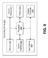
- FIG. 9illustrates components that may be utilized in a computing device 901 .
- Several of the components discussed abovemay be implemented using a computing device 901 or may include a computing device 901 . Examples of such components include the LLTS, the WALTS, the multi-mode tags, the single mode tags, etc.
- the computing device 901may include a processor 903 and memory 905 .
- the processor 903may perform logical and arithmetic operations based on program instructions, or logical definitions, stored within the memory 905 or circuits contained within the processor 903 .
- the memory 905may include any electronic component capable of storing electronic information, and may be embodied as read only memory (ROM), random access memory (RAM), magnetic disk storage media, optical storage media, flash memory devices in RAM, on-board memory included with the processor 903 , EPROM memory, EEPROM memory, registers, etc.
- the memory 905may store program instructions and other types of data.
- the program instructionsmay be executed by the processor 903 to implement some or all of the methods disclosed herein.
- the computing device 901may include one or more communication interfaces 907 for communicating with other computing devices.
- the computing device 901may also include one or more input devices 909 and one or more output devices 911 .
- One specific type of output device which may be included in the computing device 901is a display device 913 .
- a display controller 915may also be provided.
- Information and signalsmay be represented using any of a variety of different technologies and techniques.
- data, instructions, commands, information, signals, bits, symbols, and chipsthat may be referenced throughout the above description may be represented by voltages, currents, electromagnetic waves, magnetic fields or particles, optical fields or particles, or any combination thereof.
- DSPdigital signal processor
- ASICapplication specific integrated circuit
- FPGAfield programmable gate array signal
- a general purpose processormay be a microprocessor, but in the alternative, the processor may be any conventional processor, controller, microcontroller, or state machine.
- a processormay also be implemented as a combination of computing devices, e.g., a combination of a DSP and a microprocessor, a plurality of microprocessors, one or more microprocessors in conjunction with a DSP core, or any other such configuration.
- a software modulemay reside in RAM memory, flash memory, ROM memory, EPROM memory, EEPROM memory, registers, hard disk, a removable disk, a CD-ROM, or any other form of storage medium known in the art.
- An exemplary storage mediumis coupled to the processor such that the processor can read information from, and write information to, the storage medium.
- the storage mediummay be integral to the processor.
- the processor and the storage mediummay reside in an ASIC.
- the ASICmay reside in a user terminal.
- the processor and the storage mediummay reside as discrete components in a user terminal.
- the methods disclosed hereincomprise one or more steps or actions for achieving the described method.
- the method steps and/or actionsmay be interchanged with one another without departing from the scope of the present invention.
- the order and/or use of specific steps and/or actionsmay be modified without departing from the scope of the present invention.
Landscapes
- Engineering & Computer Science (AREA)
- General Physics & Mathematics (AREA)
- Business, Economics & Management (AREA)
- Physics & Mathematics (AREA)
- Economics (AREA)
- Radar, Positioning & Navigation (AREA)
- Remote Sensing (AREA)
- Entrepreneurship & Innovation (AREA)
- Development Economics (AREA)
- Human Resources & Organizations (AREA)
- Marketing (AREA)
- Operations Research (AREA)
- Quality & Reliability (AREA)
- Strategic Management (AREA)
- Tourism & Hospitality (AREA)
- General Business, Economics & Management (AREA)
- Theoretical Computer Science (AREA)
- Computer Networks & Wireless Communication (AREA)
- Mobile Radio Communication Systems (AREA)
Abstract
Description
Claims (10)
Priority Applications (3)
| Application Number | Priority Date | Filing Date | Title |
|---|---|---|---|
| US11/934,629US7969348B2 (en) | 2007-11-02 | 2007-11-02 | Systems and methods for obtaining and using data from a localized location and telemetry system in a wide area location and telemetry system |
| EP08844339AEP2218058A4 (en) | 2007-11-02 | 2008-10-29 | Systems and methods for obtaining and using data from a localized location and telemetry system in a wide area location and telemetry system |
| PCT/US2008/081611WO2009058885A2 (en) | 2007-11-02 | 2008-10-29 | Systems and methods for obtaining and using data from a localized location and telemetry system in a wide area location and telemetry system |
Applications Claiming Priority (1)
| Application Number | Priority Date | Filing Date | Title |
|---|---|---|---|
| US11/934,629US7969348B2 (en) | 2007-11-02 | 2007-11-02 | Systems and methods for obtaining and using data from a localized location and telemetry system in a wide area location and telemetry system |
Publications (2)
| Publication Number | Publication Date |
|---|---|
| US20090115608A1 US20090115608A1 (en) | 2009-05-07 |
| US7969348B2true US7969348B2 (en) | 2011-06-28 |
Family
ID=40587560
Family Applications (1)
| Application Number | Title | Priority Date | Filing Date |
|---|---|---|---|
| US11/934,629Expired - Fee RelatedUS7969348B2 (en) | 2007-11-02 | 2007-11-02 | Systems and methods for obtaining and using data from a localized location and telemetry system in a wide area location and telemetry system |
Country Status (3)
| Country | Link |
|---|---|
| US (1) | US7969348B2 (en) |
| EP (1) | EP2218058A4 (en) |
| WO (1) | WO2009058885A2 (en) |
Cited By (21)
| Publication number | Priority date | Publication date | Assignee | Title |
|---|---|---|---|---|
| US20100137021A1 (en)* | 2008-11-28 | 2010-06-03 | Eric Sharret | System, Method and Devices for Communications via a Mesh Network |
| US20140361890A1 (en)* | 2013-06-06 | 2014-12-11 | Zih Corp. | Method, apparatus, and computer program product for alert generation using health, fitness, operation, or performance of individuals |
| US9216319B2 (en) | 2010-01-05 | 2015-12-22 | Isolynx, Llc | Systems and methods for analyzing event data |
| US9375628B2 (en) | 2010-11-19 | 2016-06-28 | Isolynx, Llc | Associative object tracking systems and methods |
| US9404994B2 (en) | 2012-11-12 | 2016-08-02 | Isolynx, Llc | System and method for object tracking anti-jitter filtering |
| US9517417B2 (en) | 2013-06-06 | 2016-12-13 | Zih Corp. | Method, apparatus, and computer program product for performance analytics determining participant statistical data and game status data |
| US9566471B2 (en) | 2009-03-13 | 2017-02-14 | Isolynx, Llc | System and methods for providing performance feedback |
| US9626616B2 (en) | 2014-06-05 | 2017-04-18 | Zih Corp. | Low-profile real-time location system tag |
| US9661455B2 (en) | 2014-06-05 | 2017-05-23 | Zih Corp. | Method, apparatus, and computer program product for real time location system referencing in physically and radio frequency challenged environments |
| US9668164B2 (en) | 2014-06-05 | 2017-05-30 | Zih Corp. | Receiver processor for bandwidth management of a multiple receiver real-time location system (RTLS) |
| US9699278B2 (en) | 2013-06-06 | 2017-07-04 | Zih Corp. | Modular location tag for a real time location system network |
| US9715005B2 (en) | 2013-06-06 | 2017-07-25 | Zih Corp. | Method, apparatus, and computer program product improving real time location systems with multiple location technologies |
| US9759803B2 (en) | 2014-06-06 | 2017-09-12 | Zih Corp. | Method, apparatus, and computer program product for employing a spatial association model in a real time location system |
| US9854558B2 (en) | 2014-06-05 | 2017-12-26 | Zih Corp. | Receiver processor for adaptive windowing and high-resolution TOA determination in a multiple receiver target location system |
| US9953196B2 (en) | 2014-06-05 | 2018-04-24 | Zih Corp. | System, apparatus and methods for variable rate ultra-wideband communications |
| US10261169B2 (en) | 2014-06-05 | 2019-04-16 | Zebra Technologies Corporation | Method for iterative target location in a multiple receiver target location system |
| US10437658B2 (en) | 2013-06-06 | 2019-10-08 | Zebra Technologies Corporation | Method, apparatus, and computer program product for collecting and displaying sporting event data based on real time data for proximity and movement of objects |
| US10509099B2 (en) | 2013-06-06 | 2019-12-17 | Zebra Technologies Corporation | Method, apparatus and computer program product improving real time location systems with multiple location technologies |
| US10609762B2 (en) | 2013-06-06 | 2020-03-31 | Zebra Technologies Corporation | Method, apparatus, and computer program product improving backhaul of sensor and other data to real time location system network |
| US11391571B2 (en) | 2014-06-05 | 2022-07-19 | Zebra Technologies Corporation | Method, apparatus, and computer program for enhancement of event visualizations based on location data |
| US11423464B2 (en) | 2013-06-06 | 2022-08-23 | Zebra Technologies Corporation | Method, apparatus, and computer program product for enhancement of fan experience based on location data |
Citations (23)
| Publication number | Priority date | Publication date | Assignee | Title |
|---|---|---|---|---|
| US5742237A (en)* | 1995-11-30 | 1998-04-21 | Lockheed Martin Corporation | Tag location monitor |
| US5774876A (en)* | 1996-06-26 | 1998-06-30 | Par Government Systems Corporation | Managing assets with active electronic tags |
| US5940006A (en)* | 1995-12-12 | 1999-08-17 | Lucent Technologies Inc. | Enhanced uplink modulated backscatter system |
| US6480108B2 (en)* | 1999-05-24 | 2002-11-12 | The United States Of America As Represented By The United States Postal Service | Method and apparatus for tracking and locating a moveable article |
| US6486794B1 (en)* | 1996-02-26 | 2002-11-26 | Motorola, Inc. | Method of locating a subscriber unit within the coverage area of a communication system |
| US20030016142A1 (en) | 1999-08-16 | 2003-01-23 | Holmes John K. | Two-way wide area telemetry |
| US6552661B1 (en)* | 2000-08-25 | 2003-04-22 | Rf Code, Inc. | Zone based radio frequency identification |
| US6717516B2 (en)* | 2001-03-08 | 2004-04-06 | Symbol Technologies, Inc. | Hybrid bluetooth/RFID based real time location tracking |
| US20040090950A1 (en) | 2002-09-20 | 2004-05-13 | Ronald Lauber | Wireless digital/analog data telemetry system adapted for use with web based location information distribution method and method for developing and disseminating information for use therewith |
| US20050030015A1 (en) | 2003-07-22 | 2005-02-10 | Airak, Inc. | System and method for distributed monitoring of surroundings using telemetry of data from remote sensors |
| US20050172024A1 (en) | 2004-01-26 | 2005-08-04 | Tantalus Systems Corp. | Communications system |
| US6972682B2 (en)* | 2002-01-18 | 2005-12-06 | Georgia Tech Research Corporation | Monitoring and tracking of assets by utilizing wireless communications |
| US6985087B2 (en)* | 2002-03-15 | 2006-01-10 | Qualcomm Inc. | Method and apparatus for wireless remote telemetry using ad-hoc networks |
| US7019663B2 (en)* | 2002-08-08 | 2006-03-28 | Symbol Technologies, Inc. | RF tracking system and method |
| US20060071790A1 (en)* | 2004-09-29 | 2006-04-06 | Duron Mark W | Reverse infrastructure location system and method |
| US7030761B2 (en)* | 2004-03-16 | 2006-04-18 | Symbol Technologies | Multi-resolution object location system and method |
| US20060268961A1 (en) | 2005-05-27 | 2006-11-30 | S5 Wireless, Inc. | Burst spread spectrum radio system and method for asset tracking and data telemetry |
| US20060289647A1 (en)* | 2005-06-20 | 2006-12-28 | Microsoft Corporation | Rich object model for diverse Auto-ID tags |
| US20070296581A1 (en)* | 2006-06-23 | 2007-12-27 | Sun Microsystems, Inc. | Removable data storage media tracking system |
| US7323981B2 (en)* | 2003-02-20 | 2008-01-29 | Global Statistics, Inc. | Container tracking system |
| US20080111692A1 (en)* | 2000-12-22 | 2008-05-15 | Terahop Networks, Inc. | Radio frequency identification based sensor |
| US20080130604A1 (en)* | 2006-12-05 | 2008-06-05 | Wherenet Corp. | Location system for wireless local area network (wlan) using rssi and time difference of arrival (tdoa) processing |
| US20080254777A1 (en)* | 2007-04-10 | 2008-10-16 | S5 Wireless, Inc. | Systems and methods for facilitating automatic generation of metadata about data that is collected by a mobile device |
Family Cites Families (1)
| Publication number | Priority date | Publication date | Assignee | Title |
|---|---|---|---|---|
| US20070229356A1 (en)* | 2006-02-14 | 2007-10-04 | Kodrin David S | Devices, systems and method of determining the location of mobile personnel |
- 2007
- 2007-11-02USUS11/934,629patent/US7969348B2/ennot_activeExpired - Fee Related
- 2008
- 2008-10-29WOPCT/US2008/081611patent/WO2009058885A2/enactiveApplication Filing
- 2008-10-29EPEP08844339Apatent/EP2218058A4/ennot_activeWithdrawn
Patent Citations (24)
| Publication number | Priority date | Publication date | Assignee | Title |
|---|---|---|---|---|
| US5742237A (en)* | 1995-11-30 | 1998-04-21 | Lockheed Martin Corporation | Tag location monitor |
| US5940006A (en)* | 1995-12-12 | 1999-08-17 | Lucent Technologies Inc. | Enhanced uplink modulated backscatter system |
| US6486794B1 (en)* | 1996-02-26 | 2002-11-26 | Motorola, Inc. | Method of locating a subscriber unit within the coverage area of a communication system |
| US5774876A (en)* | 1996-06-26 | 1998-06-30 | Par Government Systems Corporation | Managing assets with active electronic tags |
| US6480108B2 (en)* | 1999-05-24 | 2002-11-12 | The United States Of America As Represented By The United States Postal Service | Method and apparatus for tracking and locating a moveable article |
| US20030016142A1 (en) | 1999-08-16 | 2003-01-23 | Holmes John K. | Two-way wide area telemetry |
| US6552661B1 (en)* | 2000-08-25 | 2003-04-22 | Rf Code, Inc. | Zone based radio frequency identification |
| US20080111692A1 (en)* | 2000-12-22 | 2008-05-15 | Terahop Networks, Inc. | Radio frequency identification based sensor |
| US6717516B2 (en)* | 2001-03-08 | 2004-04-06 | Symbol Technologies, Inc. | Hybrid bluetooth/RFID based real time location tracking |
| US6972682B2 (en)* | 2002-01-18 | 2005-12-06 | Georgia Tech Research Corporation | Monitoring and tracking of assets by utilizing wireless communications |
| US6985087B2 (en)* | 2002-03-15 | 2006-01-10 | Qualcomm Inc. | Method and apparatus for wireless remote telemetry using ad-hoc networks |
| US7019663B2 (en)* | 2002-08-08 | 2006-03-28 | Symbol Technologies, Inc. | RF tracking system and method |
| US20060125631A1 (en)* | 2002-08-08 | 2006-06-15 | Jacob Sharony | RF tracking system and method |
| US20040090950A1 (en) | 2002-09-20 | 2004-05-13 | Ronald Lauber | Wireless digital/analog data telemetry system adapted for use with web based location information distribution method and method for developing and disseminating information for use therewith |
| US7323981B2 (en)* | 2003-02-20 | 2008-01-29 | Global Statistics, Inc. | Container tracking system |
| US20050030015A1 (en) | 2003-07-22 | 2005-02-10 | Airak, Inc. | System and method for distributed monitoring of surroundings using telemetry of data from remote sensors |
| US20050172024A1 (en) | 2004-01-26 | 2005-08-04 | Tantalus Systems Corp. | Communications system |
| US7030761B2 (en)* | 2004-03-16 | 2006-04-18 | Symbol Technologies | Multi-resolution object location system and method |
| US20060071790A1 (en)* | 2004-09-29 | 2006-04-06 | Duron Mark W | Reverse infrastructure location system and method |
| US20060268961A1 (en) | 2005-05-27 | 2006-11-30 | S5 Wireless, Inc. | Burst spread spectrum radio system and method for asset tracking and data telemetry |
| US20060289647A1 (en)* | 2005-06-20 | 2006-12-28 | Microsoft Corporation | Rich object model for diverse Auto-ID tags |
| US20070296581A1 (en)* | 2006-06-23 | 2007-12-27 | Sun Microsystems, Inc. | Removable data storage media tracking system |
| US20080130604A1 (en)* | 2006-12-05 | 2008-06-05 | Wherenet Corp. | Location system for wireless local area network (wlan) using rssi and time difference of arrival (tdoa) processing |
| US20080254777A1 (en)* | 2007-04-10 | 2008-10-16 | S5 Wireless, Inc. | Systems and methods for facilitating automatic generation of metadata about data that is collected by a mobile device |
Non-Patent Citations (1)
| Title |
|---|
| International Preliminary Report on Patentability issued for International Patent Application No. PCT/US2008/081611 on May 14, 2010. |
Cited By (55)
| Publication number | Priority date | Publication date | Assignee | Title |
|---|---|---|---|---|
| US20100137021A1 (en)* | 2008-11-28 | 2010-06-03 | Eric Sharret | System, Method and Devices for Communications via a Mesh Network |
| US9566471B2 (en) | 2009-03-13 | 2017-02-14 | Isolynx, Llc | System and methods for providing performance feedback |
| US9849334B2 (en) | 2010-01-05 | 2017-12-26 | Isolynx, Llc | Systems and methods for analyzing event data |
| US9216319B2 (en) | 2010-01-05 | 2015-12-22 | Isolynx, Llc | Systems and methods for analyzing event data |
| US10420981B2 (en) | 2010-01-05 | 2019-09-24 | Isolynx, Llc | Systems and methods for analyzing event data |
| US10071282B2 (en) | 2010-11-19 | 2018-09-11 | Isolynx, Llc | Associative object tracking systems and methods |
| US9375628B2 (en) | 2010-11-19 | 2016-06-28 | Isolynx, Llc | Associative object tracking systems and methods |
| US9795830B2 (en) | 2010-11-19 | 2017-10-24 | Isolynx, Llc | Associative object tracking systems and methods |
| US10191139B2 (en) | 2012-11-12 | 2019-01-29 | Isolynx, Llc | System and method for object tracking anti-jitter filtering |
| US9404994B2 (en) | 2012-11-12 | 2016-08-02 | Isolynx, Llc | System and method for object tracking anti-jitter filtering |
| US11408969B2 (en) | 2012-11-12 | 2022-08-09 | Isolynx, Llc | System and method for object tracking anti-jitter filtering |
| US9742450B2 (en) | 2013-06-06 | 2017-08-22 | Zih Corp. | Method, apparatus, and computer program product improving registration with real time location services |
| US11023303B2 (en) | 2013-06-06 | 2021-06-01 | Zebra Technologies Corporation | Methods and apparatus to correlate unique identifiers and tag-individual correlators based on status change indications |
| US9667287B2 (en) | 2013-06-06 | 2017-05-30 | Zih Corp. | Multiple antenna interference rejection in ultra-wideband real time locating systems |
| US11423464B2 (en) | 2013-06-06 | 2022-08-23 | Zebra Technologies Corporation | Method, apparatus, and computer program product for enhancement of fan experience based on location data |
| US9699278B2 (en) | 2013-06-06 | 2017-07-04 | Zih Corp. | Modular location tag for a real time location system network |
| US9698841B2 (en) | 2013-06-06 | 2017-07-04 | Zih Corp. | Method and apparatus for associating radio frequency identification tags with participants |
| US9715005B2 (en) | 2013-06-06 | 2017-07-25 | Zih Corp. | Method, apparatus, and computer program product improving real time location systems with multiple location technologies |
| US9602152B2 (en) | 2013-06-06 | 2017-03-21 | Zih Corp. | Method, apparatus, and computer program product for determining play events and outputting events based on real-time data for proximity, movement of objects, and audio data |
| US9531415B2 (en) | 2013-06-06 | 2016-12-27 | Zih Corp. | Systems and methods for activity determination based on human frame |
| US9517417B2 (en) | 2013-06-06 | 2016-12-13 | Zih Corp. | Method, apparatus, and computer program product for performance analytics determining participant statistical data and game status data |
| US9839809B2 (en) | 2013-06-06 | 2017-12-12 | Zih Corp. | Method, apparatus, and computer program product for determining play events and outputting events based on real-time data for proximity, movement of objects, and audio data |
| US9014830B2 (en) | 2013-06-06 | 2015-04-21 | Zih Corp. | Method, apparatus, and computer program product for combined tag and sensor based performance modeling using real-time data for proximity and movement of objects |
| US11287511B2 (en) | 2013-06-06 | 2022-03-29 | Zebra Technologies Corporation | Method, apparatus, and computer program product improving real time location systems with multiple location technologies |
| US12360837B2 (en) | 2013-06-06 | 2025-07-15 | Zebra Technologies Corporation | Method, apparatus, and computer program product for collecting and displaying sporting event data based on real time data for proximity and movement of objects |
| US9882592B2 (en) | 2013-06-06 | 2018-01-30 | Zih Corp. | Method, apparatus, and computer program product for tag and individual correlation |
| US10778268B2 (en) | 2013-06-06 | 2020-09-15 | Zebra Technologies Corporation | Method, apparatus, and computer program product for performance analytics determining play models and outputting events based on real-time data for proximity and movement of objects |
| US10707908B2 (en) | 2013-06-06 | 2020-07-07 | Zebra Technologies Corporation | Method, apparatus, and computer program product for evaluating performance based on real-time data for proximity and movement of objects |
| US9985672B2 (en) | 2013-06-06 | 2018-05-29 | Zih Corp. | Method, apparatus, and computer program product for evaluating performance based on real-time data for proximity and movement of objects |
| US10050650B2 (en) | 2013-06-06 | 2018-08-14 | Zih Corp. | Method, apparatus, and computer program product improving registration with real time location services |
| US9002485B2 (en) | 2013-06-06 | 2015-04-07 | Zih Corp. | Method, apparatus, and computer program product for performance analytics determining play models and outputting events based on real-time data for proximity and movement of objects |
| US20140361890A1 (en)* | 2013-06-06 | 2014-12-11 | Zih Corp. | Method, apparatus, and computer program product for alert generation using health, fitness, operation, or performance of individuals |
| US10212262B2 (en) | 2013-06-06 | 2019-02-19 | Zebra Technologies Corporation | Modular location tag for a real time location system network |
| US10218399B2 (en) | 2013-06-06 | 2019-02-26 | Zebra Technologies Corporation | Systems and methods for activity determination based on human frame |
| US10609762B2 (en) | 2013-06-06 | 2020-03-31 | Zebra Technologies Corporation | Method, apparatus, and computer program product improving backhaul of sensor and other data to real time location system network |
| US10509099B2 (en) | 2013-06-06 | 2019-12-17 | Zebra Technologies Corporation | Method, apparatus and computer program product improving real time location systems with multiple location technologies |
| US10437658B2 (en) | 2013-06-06 | 2019-10-08 | Zebra Technologies Corporation | Method, apparatus, and computer program product for collecting and displaying sporting event data based on real time data for proximity and movement of objects |
| US10333568B2 (en) | 2013-06-06 | 2019-06-25 | Zebra Technologies Corporation | Method and apparatus for associating radio frequency identification tags with participants |
| US10421020B2 (en) | 2013-06-06 | 2019-09-24 | Zebra Technologies Corporation | Method, apparatus, and computer program product for performance analytics determining participant statistical data and game status data |
| US9661455B2 (en) | 2014-06-05 | 2017-05-23 | Zih Corp. | Method, apparatus, and computer program product for real time location system referencing in physically and radio frequency challenged environments |
| US9668164B2 (en) | 2014-06-05 | 2017-05-30 | Zih Corp. | Receiver processor for bandwidth management of a multiple receiver real-time location system (RTLS) |
| US10285157B2 (en) | 2014-06-05 | 2019-05-07 | Zebra Technologies Corporation | Receiver processor for adaptive windowing and high-resolution TOA determination in a multiple receiver target location system |
| US10520582B2 (en) | 2014-06-05 | 2019-12-31 | Zebra Technologies Corporation | Method for iterative target location in a multiple receiver target location system |
| US10310052B2 (en) | 2014-06-05 | 2019-06-04 | Zebra Technologies Corporation | Method, apparatus, and computer program product for real time location system referencing in physically and radio frequency challenged environments |
| US10261169B2 (en) | 2014-06-05 | 2019-04-16 | Zebra Technologies Corporation | Method for iterative target location in a multiple receiver target location system |
| US9953195B2 (en) | 2014-06-05 | 2018-04-24 | Zih Corp. | Systems, apparatus and methods for variable rate ultra-wideband communications |
| US9953196B2 (en) | 2014-06-05 | 2018-04-24 | Zih Corp. | System, apparatus and methods for variable rate ultra-wideband communications |
| US10942248B2 (en) | 2014-06-05 | 2021-03-09 | Zebra Technologies Corporation | Method, apparatus, and computer program product for real time location system referencing in physically and radio frequency challenged environments |
| US9864946B2 (en) | 2014-06-05 | 2018-01-09 | Zih Corp. | Low-profile real-time location system tag |
| US9626616B2 (en) | 2014-06-05 | 2017-04-18 | Zih Corp. | Low-profile real-time location system tag |
| US9854558B2 (en) | 2014-06-05 | 2017-12-26 | Zih Corp. | Receiver processor for adaptive windowing and high-resolution TOA determination in a multiple receiver target location system |
| US11391571B2 (en) | 2014-06-05 | 2022-07-19 | Zebra Technologies Corporation | Method, apparatus, and computer program for enhancement of event visualizations based on location data |
| US10591578B2 (en) | 2014-06-06 | 2020-03-17 | Zebra Technologies Corporation | Method, apparatus, and computer program product for employing a spatial association model in a real time location system |
| US9759803B2 (en) | 2014-06-06 | 2017-09-12 | Zih Corp. | Method, apparatus, and computer program product for employing a spatial association model in a real time location system |
| US11156693B2 (en) | 2014-06-06 | 2021-10-26 | Zebra Technologies Corporation | Method, apparatus, and computer program product for employing a spatial association model in a real time location system |
Also Published As
| Publication number | Publication date |
|---|---|
| WO2009058885A2 (en) | 2009-05-07 |
| US20090115608A1 (en) | 2009-05-07 |
| EP2218058A4 (en) | 2012-04-25 |
| EP2218058A2 (en) | 2010-08-18 |
| WO2009058885A3 (en) | 2009-12-30 |
Similar Documents
| Publication | Publication Date | Title |
|---|---|---|
| US7969348B2 (en) | Systems and methods for obtaining and using data from a localized location and telemetry system in a wide area location and telemetry system | |
| US11231479B2 (en) | Frequency channel diversity for real-time locating systems, methods, and computer program products | |
| EP2481236B1 (en) | Method to reduce database load in real time location systems | |
| US7630323B2 (en) | Self-configuring wireless personal area network | |
| EP2497310B1 (en) | Location detection in a wireless network | |
| US20180293862A1 (en) | System and method for automatic tool tracking, monitoring, and inventory management | |
| CN102170696A (en) | CUCKOO hashing to store beacon reference data | |
| US20200410866A1 (en) | Vehicle location tracking systems and methods | |
| US20080079577A1 (en) | Methods and apparatus for opportunistic locationing of RF tags | |
| GB2550326A (en) | Asset tag and method and device for asset tracking | |
| EP3836575B1 (en) | Location tracking of assets | |
| US20140327541A1 (en) | System and method for tracking firearms | |
| US20090036066A1 (en) | Smart data dynamic communication module and message processing and transmitting method thereof | |
| EP2196816A1 (en) | Real time location system with ZigBee technology | |
| CN112470197B (en) | Method for providing low power IoT communication based geofencing services based on context aware information of location tracking devices | |
| Bernardy et al. | Basic Methodology for cyber physical system modelling | |
| US8615265B2 (en) | Coded system for radio frequency communication | |
| EP4189981B1 (en) | System and method for integrated wireless data transmission with implicit location and timestamp with a location symbol | |
| Mitsugi et al. | Enabling globally unique sensor ID with dual-interface RF tag | |
| US20090197530A1 (en) | Guard tour system utilizing mote networks | |
| EP4027662B1 (en) | Monitoring system for determining the location of bluetooth beacons | |
| GB2570479A (en) | Object location using wireless communication protocols | |
| CN101661551B (en) | Identifying and positioning method of radio frequency identification reading devices and reading devices | |
| PENKOV et al. | Industrial network design using low energy protocols | |
| Bellander et al. | Produktspårning med RFID: Konceptutveckling och utvärdering |
Legal Events
| Date | Code | Title | Description |
|---|---|---|---|
| AS | Assignment | Owner name:S5 WIRELESS, INC., UTAH Free format text:ASSIGNMENT OF ASSIGNORS INTEREST;ASSIGNORS:BAKER, JAMES R.;PRESTWICH, SY;BEVAN, SCOTT;REEL/FRAME:020068/0315 Effective date:20071026 | |
| AS | Assignment | Owner name:EAGLE RIVER HOLDINGS, LLC, AS AGENT FOR ITSELF AND Free format text:SECURITY AGREEMENT;ASSIGNOR:S5 WIRELESS, INC.;REEL/FRAME:020451/0728 Effective date:20080124 | |
| AS | Assignment | Owner name:EAGLE RIVER HOLDINGS, LLC (A WASHINGTON LLC), AS A Free format text:SECURITY AGREEMENT;ASSIGNOR:S5 WIRELESS, INC. (A DELAWARE CORPORATION);REEL/FRAME:021029/0759 Effective date:20080523 | |
| AS | Assignment | Owner name:EAGLE RIVER HOLDINGS, LLC, AS AGENT FOR ITSELF AND Free format text:SECURITY AGREEMENT;ASSIGNOR:S5 WIRELESS, INC.;REEL/FRAME:021423/0820 Effective date:20080813 | |
| AS | Assignment | Owner name:EAGLE RIVER HOLDINGS, LLC, AS AGENT FOR ITSELF AND Free format text:SECURITY AGREEMENT;ASSIGNOR:S5 WIRELESS, INC.;REEL/FRAME:022320/0370 Effective date:20090129 | |
| AS | Assignment | Owner name:S5 WIRELESS, INC.,UTAH Free format text:NOTICE OF RELEASE OF SECURITY INTEREST;ASSIGNOR:EAGLE RIVER HOLDINGS, LLC;REEL/FRAME:024555/0862 Effective date:20100614 Owner name:RECON DYNAMICS, LLC,WASHINGTON Free format text:NUNC PRO TUNC ASSIGNMENT;ASSIGNOR:S5 WIRELESS, INC.;REEL/FRAME:024555/0870 Effective date:20100527 Owner name:S5 WIRELESS, INC., UTAH Free format text:NOTICE OF RELEASE OF SECURITY INTEREST;ASSIGNOR:EAGLE RIVER HOLDINGS, LLC;REEL/FRAME:024555/0862 Effective date:20100614 Owner name:RECON DYNAMICS, LLC, WASHINGTON Free format text:NUNC PRO TUNC ASSIGNMENT;ASSIGNOR:S5 WIRELESS, INC.;REEL/FRAME:024555/0870 Effective date:20100527 | |
| STCF | Information on status: patent grant | Free format text:PATENTED CASE | |
| FPAY | Fee payment | Year of fee payment:4 | |
| FEPP | Fee payment procedure | Free format text:MAINTENANCE FEE REMINDER MAILED (ORIGINAL EVENT CODE: REM.); ENTITY STATUS OF PATENT OWNER: SMALL ENTITY | |
| FEPP | Fee payment procedure | Free format text:7.5 YR SURCHARGE - LATE PMT W/IN 6 MO, SMALL ENTITY (ORIGINAL EVENT CODE: M2555); ENTITY STATUS OF PATENT OWNER: SMALL ENTITY | |
| MAFP | Maintenance fee payment | Free format text:PAYMENT OF MAINTENANCE FEE, 8TH YR, SMALL ENTITY (ORIGINAL EVENT CODE: M2552); ENTITY STATUS OF PATENT OWNER: SMALL ENTITY Year of fee payment:8 | |
| FEPP | Fee payment procedure | Free format text:MAINTENANCE FEE REMINDER MAILED (ORIGINAL EVENT CODE: REM.); ENTITY STATUS OF PATENT OWNER: SMALL ENTITY | |
| LAPS | Lapse for failure to pay maintenance fees | Free format text:PATENT EXPIRED FOR FAILURE TO PAY MAINTENANCE FEES (ORIGINAL EVENT CODE: EXP.); ENTITY STATUS OF PATENT OWNER: SMALL ENTITY | |
| STCH | Information on status: patent discontinuation | Free format text:PATENT EXPIRED DUE TO NONPAYMENT OF MAINTENANCE FEES UNDER 37 CFR 1.362 | |
| FP | Lapsed due to failure to pay maintenance fee | Effective date:20230628 |