US7969156B2 - Method and apparatus for monitoring a load - Google Patents
Method and apparatus for monitoring a loadDownload PDFInfo
- Publication number
- US7969156B2 US7969156B2US12/045,262US4526208AUS7969156B2US 7969156 B2US7969156 B2US 7969156B2US 4526208 AUS4526208 AUS 4526208AUS 7969156 B2US7969156 B2US 7969156B2
- Authority
- US
- United States
- Prior art keywords
- load
- sensing
- module
- electrical
- power
- Prior art date
- Legal status (The legal status is an assumption and is not a legal conclusion. Google has not performed a legal analysis and makes no representation as to the accuracy of the status listed.)
- Active, expires
Links
Images


Classifications
- H—ELECTRICITY
- H02—GENERATION; CONVERSION OR DISTRIBUTION OF ELECTRIC POWER
- H02J—CIRCUIT ARRANGEMENTS OR SYSTEMS FOR SUPPLYING OR DISTRIBUTING ELECTRIC POWER; SYSTEMS FOR STORING ELECTRIC ENERGY
- H02J13/00—Circuit arrangements for providing remote indication of network conditions, e.g. an instantaneous record of the open or closed condition of each circuitbreaker in the network; Circuit arrangements for providing remote control of switching means in a power distribution network, e.g. switching in and out of current consumers by using a pulse code signal carried by the network
- H02J13/00002—Circuit arrangements for providing remote indication of network conditions, e.g. an instantaneous record of the open or closed condition of each circuitbreaker in the network; Circuit arrangements for providing remote control of switching means in a power distribution network, e.g. switching in and out of current consumers by using a pulse code signal carried by the network characterised by monitoring
- H—ELECTRICITY
- H02—GENERATION; CONVERSION OR DISTRIBUTION OF ELECTRIC POWER
- H02J—CIRCUIT ARRANGEMENTS OR SYSTEMS FOR SUPPLYING OR DISTRIBUTING ELECTRIC POWER; SYSTEMS FOR STORING ELECTRIC ENERGY
- H02J13/00—Circuit arrangements for providing remote indication of network conditions, e.g. an instantaneous record of the open or closed condition of each circuitbreaker in the network; Circuit arrangements for providing remote control of switching means in a power distribution network, e.g. switching in and out of current consumers by using a pulse code signal carried by the network
- H02J13/00032—Systems characterised by the controlled or operated power network elements or equipment, the power network elements or equipment not otherwise provided for
- H02J13/0005—Systems characterised by the controlled or operated power network elements or equipment, the power network elements or equipment not otherwise provided for the elements or equipment being or involving power plugs or sockets
- H—ELECTRICITY
- H02—GENERATION; CONVERSION OR DISTRIBUTION OF ELECTRIC POWER
- H02J—CIRCUIT ARRANGEMENTS OR SYSTEMS FOR SUPPLYING OR DISTRIBUTING ELECTRIC POWER; SYSTEMS FOR STORING ELECTRIC ENERGY
- H02J13/00—Circuit arrangements for providing remote indication of network conditions, e.g. an instantaneous record of the open or closed condition of each circuitbreaker in the network; Circuit arrangements for providing remote control of switching means in a power distribution network, e.g. switching in and out of current consumers by using a pulse code signal carried by the network
- H02J13/00006—Circuit arrangements for providing remote indication of network conditions, e.g. an instantaneous record of the open or closed condition of each circuitbreaker in the network; Circuit arrangements for providing remote control of switching means in a power distribution network, e.g. switching in and out of current consumers by using a pulse code signal carried by the network characterised by information or instructions transport means between the monitoring, controlling or managing units and monitored, controlled or operated power network element or electrical equipment
- H02J13/00016—Circuit arrangements for providing remote indication of network conditions, e.g. an instantaneous record of the open or closed condition of each circuitbreaker in the network; Circuit arrangements for providing remote control of switching means in a power distribution network, e.g. switching in and out of current consumers by using a pulse code signal carried by the network characterised by information or instructions transport means between the monitoring, controlling or managing units and monitored, controlled or operated power network element or electrical equipment using a wired telecommunication network or a data transmission bus
- H—ELECTRICITY
- H02—GENERATION; CONVERSION OR DISTRIBUTION OF ELECTRIC POWER
- H02J—CIRCUIT ARRANGEMENTS OR SYSTEMS FOR SUPPLYING OR DISTRIBUTING ELECTRIC POWER; SYSTEMS FOR STORING ELECTRIC ENERGY
- H02J13/00—Circuit arrangements for providing remote indication of network conditions, e.g. an instantaneous record of the open or closed condition of each circuitbreaker in the network; Circuit arrangements for providing remote control of switching means in a power distribution network, e.g. switching in and out of current consumers by using a pulse code signal carried by the network
- H02J13/00006—Circuit arrangements for providing remote indication of network conditions, e.g. an instantaneous record of the open or closed condition of each circuitbreaker in the network; Circuit arrangements for providing remote control of switching means in a power distribution network, e.g. switching in and out of current consumers by using a pulse code signal carried by the network characterised by information or instructions transport means between the monitoring, controlling or managing units and monitored, controlled or operated power network element or electrical equipment
- H02J13/00022—Circuit arrangements for providing remote indication of network conditions, e.g. an instantaneous record of the open or closed condition of each circuitbreaker in the network; Circuit arrangements for providing remote control of switching means in a power distribution network, e.g. switching in and out of current consumers by using a pulse code signal carried by the network characterised by information or instructions transport means between the monitoring, controlling or managing units and monitored, controlled or operated power network element or electrical equipment using wireless data transmission
- Y—GENERAL TAGGING OF NEW TECHNOLOGICAL DEVELOPMENTS; GENERAL TAGGING OF CROSS-SECTIONAL TECHNOLOGIES SPANNING OVER SEVERAL SECTIONS OF THE IPC; TECHNICAL SUBJECTS COVERED BY FORMER USPC CROSS-REFERENCE ART COLLECTIONS [XRACs] AND DIGESTS
- Y02—TECHNOLOGIES OR APPLICATIONS FOR MITIGATION OR ADAPTATION AGAINST CLIMATE CHANGE
- Y02E—REDUCTION OF GREENHOUSE GAS [GHG] EMISSIONS, RELATED TO ENERGY GENERATION, TRANSMISSION OR DISTRIBUTION
- Y02E60/00—Enabling technologies; Technologies with a potential or indirect contribution to GHG emissions mitigation
- Y—GENERAL TAGGING OF NEW TECHNOLOGICAL DEVELOPMENTS; GENERAL TAGGING OF CROSS-SECTIONAL TECHNOLOGIES SPANNING OVER SEVERAL SECTIONS OF THE IPC; TECHNICAL SUBJECTS COVERED BY FORMER USPC CROSS-REFERENCE ART COLLECTIONS [XRACs] AND DIGESTS
- Y04—INFORMATION OR COMMUNICATION TECHNOLOGIES HAVING AN IMPACT ON OTHER TECHNOLOGY AREAS
- Y04S—SYSTEMS INTEGRATING TECHNOLOGIES RELATED TO POWER NETWORK OPERATION, COMMUNICATION OR INFORMATION TECHNOLOGIES FOR IMPROVING THE ELECTRICAL POWER GENERATION, TRANSMISSION, DISTRIBUTION, MANAGEMENT OR USAGE, i.e. SMART GRIDS
- Y04S10/00—Systems supporting electrical power generation, transmission or distribution
- Y04S10/30—State monitoring, e.g. fault, temperature monitoring, insulator monitoring, corona discharge
- Y—GENERAL TAGGING OF NEW TECHNOLOGICAL DEVELOPMENTS; GENERAL TAGGING OF CROSS-SECTIONAL TECHNOLOGIES SPANNING OVER SEVERAL SECTIONS OF THE IPC; TECHNICAL SUBJECTS COVERED BY FORMER USPC CROSS-REFERENCE ART COLLECTIONS [XRACs] AND DIGESTS
- Y04—INFORMATION OR COMMUNICATION TECHNOLOGIES HAVING AN IMPACT ON OTHER TECHNOLOGY AREAS
- Y04S—SYSTEMS INTEGRATING TECHNOLOGIES RELATED TO POWER NETWORK OPERATION, COMMUNICATION OR INFORMATION TECHNOLOGIES FOR IMPROVING THE ELECTRICAL POWER GENERATION, TRANSMISSION, DISTRIBUTION, MANAGEMENT OR USAGE, i.e. SMART GRIDS
- Y04S40/00—Systems for electrical power generation, transmission, distribution or end-user application management characterised by the use of communication or information technologies, or communication or information technology specific aspects supporting them
- Y04S40/12—Systems for electrical power generation, transmission, distribution or end-user application management characterised by the use of communication or information technologies, or communication or information technology specific aspects supporting them characterised by data transport means between the monitoring, controlling or managing units and monitored, controlled or operated electrical equipment
- Y04S40/124—Systems for electrical power generation, transmission, distribution or end-user application management characterised by the use of communication or information technologies, or communication or information technology specific aspects supporting them characterised by data transport means between the monitoring, controlling or managing units and monitored, controlled or operated electrical equipment using wired telecommunication networks or data transmission busses
- Y—GENERAL TAGGING OF NEW TECHNOLOGICAL DEVELOPMENTS; GENERAL TAGGING OF CROSS-SECTIONAL TECHNOLOGIES SPANNING OVER SEVERAL SECTIONS OF THE IPC; TECHNICAL SUBJECTS COVERED BY FORMER USPC CROSS-REFERENCE ART COLLECTIONS [XRACs] AND DIGESTS
- Y04—INFORMATION OR COMMUNICATION TECHNOLOGIES HAVING AN IMPACT ON OTHER TECHNOLOGY AREAS
- Y04S—SYSTEMS INTEGRATING TECHNOLOGIES RELATED TO POWER NETWORK OPERATION, COMMUNICATION OR INFORMATION TECHNOLOGIES FOR IMPROVING THE ELECTRICAL POWER GENERATION, TRANSMISSION, DISTRIBUTION, MANAGEMENT OR USAGE, i.e. SMART GRIDS
- Y04S40/00—Systems for electrical power generation, transmission, distribution or end-user application management characterised by the use of communication or information technologies, or communication or information technology specific aspects supporting them
- Y04S40/12—Systems for electrical power generation, transmission, distribution or end-user application management characterised by the use of communication or information technologies, or communication or information technology specific aspects supporting them characterised by data transport means between the monitoring, controlling or managing units and monitored, controlled or operated electrical equipment
- Y04S40/126—Systems for electrical power generation, transmission, distribution or end-user application management characterised by the use of communication or information technologies, or communication or information technology specific aspects supporting them characterised by data transport means between the monitoring, controlling or managing units and monitored, controlled or operated electrical equipment using wireless data transmission
Definitions
- the inventions disclosed and taught hereinrelate generally to monitoring a load in a power distribution system; and, more specifically, relate to a method and apparatus for remotely monitoring a load in a power distribution system adapted to validate the performance of a load sensing in an apparatus.
- U.S. Pat. No. 5,281,859 to Cranediscloses an “automatically switched power receptacle,” in which a switched power circuit selectively connects an electrical load to any one of a plurality of branch power circuits.
- the switched power circuitincludes a sensing circuit for sensing electrical loading on each of the branch circuits.
- a logic circuitis coupled to the sensing circuit for selecting one of the branch circuits to be connected to the load according to the sensed loading to provide balanced loading on each branch circuit.
- U.S. Pat. No. 5,424,903 to Schreiberdiscloses an “intelligent power switcher,” in which an intelligent power switching system is disclosed for controlling the electrical connection of a power source to each of a plurality of outputs, such as personal computers components or electronic entertainment equipment.
- Switch circuitryis coupled to relay circuitry for generating signals responsive to user commands to select an “on” or “off” state with respect to each output.
- U.S. Pat. No. 5,862,393 to Davisdiscloses a “system for managing power of a computer with removable devices.”
- the patentdiscloses a system for managing power consumption by communicating power management events to a removable device of the computer.
- a device removal signalis transmitted to a device controller for the removable device while the device is installed within a socket of a computer.
- This device removal signalcan provide notice of a power state change for the device, such as the interruption of electrical power to that device.
- the power state changeis communicated by the device controller to a device driver in response to the device removal signal. Electrical power to the device is terminated in response to the power management event.
- a device insertion signalis transmitted to the device controller in response to another power management event and while the device remains installed within the socket. This device insertion signal provides notice of another state change for the device. Electrical power is reapplied to the device in response to this power management event.
- the apparatusincludes an electrically powered device having a key operating line and switching control circuitry to control usage of the electrically powered device by interrupting continuity of the key operating line.
- the power stripscan each include an elongated housing that may be adapted for mounting in an equipment rack.
- the power stripsfurther include power management circuitry that can power-on and power-off the power outlets in accordance with an operator defined sequence and delays.
- the power management circuitrycan further sense electrical current drawn by the power strip and control operation of the power strip based on the sensed electrical current to minimize branch circuit breaker tripping.
- U.S. Pat. No. 6,744,150 to Rendic, issued Jun. 1, 2004,discloses an “outlet strip controlled by PC using low voltage powertap.”
- the patentdiscloses an improved electrical power strip which will automatically energize or de-energize one or more devices which are plugged into the strip, upon receiving an electrical signal from the primary device, without need for manual actuation of a switch on the electrical strip or an under monitor system by the user.
- the systemuses a low voltage power tap connector which is plugged in any appropriate socket of the primary device (which may be a personal computer) to sense the primary status of the power supply.
- the output signaltriggers a synchronous transfer switch or relay which enables power to secondary devices, permitting them to be synchronously turned on or off depending on the computer status.
- U.S. Pat. No. 6,937,461 to Donahue, IV, issued Aug. 30, 2005discloses a “modular power distribution unit, module for the power distribution unit, and method of using the same.”
- the patentdiscloses a modular power distribution unit for supplying electric power to attached equipment in environments such as data centers, computer rooms, and communication centers, where power requirement for attached equipment may vary.
- the power distribution unitincludes a frame and one or more user-replaceable power modules, which fit into slots in the frame.
- Each power moduleprovides one or more plug receptacle types, receptacle numbers, and power rating configuration to accommodate various equipment in a particular environment, as needed.
- the power modulesmay be removed, installed and interchanged in the frame without interrupting power to other modules or to the power distribution unit.
- the inventions disclosed and taught hereinare directed to a method and apparatus for monitoring a load.
- the apparatusincludes an intelligent power distribution module that can include a power output section, a power input section, a communication section, and related circuitry.
- the intelligent power distribution modulecan further include a memory section, a sensing device, a processing device, and a switch.
- the disclosurealso provides a method for monitoring an electrical load having a current and voltage requirement supplied by an electrical source coupled to the load, generally including interfacing a sensing module between the load and the electrical source, sensing one or more characteristics of the load, and determining the performance, including, but not limited to, accuracy and validity, of the load sensing.
- FIG. 1illustrates an exemplary embodiment of the intelligent power distribution module.
- FIG. 2illustrates the intelligent power distribution module in an intelligent power distribution system.
- FIG. 3illustrates another embodiment of the intelligent power distribution module in an intelligent power distribution system.
- FIG. 4illustrates another embodiment of the intelligent power distribution module in an intelligent power distribution system.
- FIG. 4Aillustrates another embodiment of the intelligent power distribution module in an intelligent power distribution system
- FIG. 5is an exemplary systematic diagram illustrating determining the accuracy of results from monitoring an electrical load.
- FIG. 6illustrates an embodiment of the calibration waveform.
- FIG. 7illustrates an embodiment of a superposition waveform.
- the apparatusincludes an intelligent power distribution module that can include a power output section, a power input section, a communication section, and related circuitry.
- the modulecan further include a memory section, a sensing-device, a processing device, and a switch.
- the method for monitoring an electrical load having a current and voltage requirement supplied by an electrical source coupled to the loadgenerally includes: interfacing a sensing module between the load and the source for sensing one or more characteristics of the load; analyzing power-related anomalies and line disturbances caused or created by the electrical load; sensing one or more characteristics of the load; and determining the performance, including, but not limited to, accuracy and validity, of the load sensing.
- a power modulecan receive electrical power from a power input section and route the power through a switched device to a power output section to a load.
- the intelligent power distribution module 2 of the present disclosureis an improvement on prior art modules.
- the intelligent power distribution module 2in an exemplary embodiment allows users to automatically calibrate and determine the performance, including, but not limited to, accuracy and validity, of the load sensing of the intelligent power distribution module 2 .
- the intelligent power distribution modulesmay have different power ratings, different power receptacles, different sensing-devices, or plugs.
- FIG. 1illustrates an exemplary embodiment of the intelligent power distribution module.
- the intelligent power distribution modulegenerally includes: a power output section 10 , a power input section 15 , a communication section 25 and related circuitry, which generally includes a memory section 30 , a sensing device 35 , a processing device 40 , and switch 20 adapted to determine the performance, including, but not limited to, accuracy and validity, of the load sensing.
- the various elementswill be described in more detail below.
- the input power section 15is a connection device adapted to connect with and receive electrical power from a power source 50 . Further details are shown and described in FIGS. 2-5 .
- the power sources used in a power distribution system utilizing the intelligent power distribution module 2can include, for example, an electrical power wall socket, an electrical power rail, an electrical power strip, a branch circuit monitoring system (“BCMS”), or a Liebert distributed monitoring system (“LDM”).
- the input power section 15may be embodied by any power plug, such as a safety agency recognized standard power plug, for example, a National Electrical Manufacturers Association (“NEMA”) 5-15P or NEMA L5-20P. In the embodiment illustrated in FIG. 1 , the power output section 15 is shown to have the dimensional and electrical specifications of a NEMA 5-15P plug.
- the intelligent power distribution module 2may be configured to have one or more power input sections 15 .
- the related circuitrygenerally includes a memory section 30 , a sensing device 35 , a processing device 40 , and a switch 20 and is adapted to determine the performance, including, but not limited to, accuracy and validity, of the load sensing.
- the memory section 30may be embodied by any number of storage devices. Without limitation, the memory section 30 can be electrically erasable programmable read-only memory.
- the memory section 30is adapted to store data. This data could include, for example, reference data, current levels, power consumption, or communications from other components in the power distribution system.
- the processing device 40is a device adapted to control the intelligent power distribution module including, for example, controlling various functions of the sensing and/or monitoring functions.
- the processing device 40can calculate values used in calibrating and determining the performance, including, but not limited, accuracy and validity, of the load sensing.
- the intelligent power distribution module 2comprises a display 60 indicating the status of the module. This display, for example, can display that data has been sent, the module is calibrating, the module needs to be replaced, or a power quality problem is evident.
- the communication section 25is a device adapted to transmit data to and from the intelligent power distribution module 2 .
- the communication section 25may communicate, for example, by wired or wireless signals.
- the communication section 25is a wired communication bus.
- the communication section 25may communicate in a number of ways. Three examples are offered and other ways are available. First, the communication section 25 may communicate over the electrical pathway from the power source 15 . Second, the communication section may communicate over a dedicated wired communication signal, such as a bus. Third, the communication section may communicate over a wireless signal with a remote station, for example, with the power source or some other component of the power distribution system.
- the power output section 10is a connection device adapted to connect with and transfer electrical power to one or more loads 45 . Further details are shown and described in FIGS. 2-5 .
- the power output section 10may be embodied by any power receptacle, such as a safety agency recognized standard power receptacle, for example, a NEMA 5-15R or an IEC 60320-2-2-Sheet F (C13) outlet. In the embodiment illustrated in FIG. 1 , the power output section 10 is shown to be a cross section of a C13 outlet.
- the intelligent power distribution module 2can be configured to have one or more power output sections 10 .
- FIGS. 2-5illustrate the intelligent power distribution module 2 and exemplary variations in a power distribution system. These figures will show a few illustrations of the many different embodiments of intelligent power distribution modules 2 and related systems.
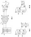
- FIG. 2illustrates the intelligent power distribution module in an intelligent power distribution system.
- the systemincludes an electrical power source 50 , illustrated here as a power strip, connected to an intelligent power distribution module 2 , and an electrical power load 45 , illustrated here as a NEMA 5-15P plug, connected to the intelligent power distribution module 2 .
- the communication section 25is wireless.
- the wireless communication section 25allows the intelligent power distribution module 2 to wirelessly transmit and receive data from and to the intelligent power distribution module 2 .
- the wireless communication sectioncan transmit data, for example, one or more characteristics of the load sensing or of a module, from or to a remote location.
- a remote locationcan include, for example, another intelligent power distribution module or any other system.
- FIG. 3illustrates another embodiment of the intelligent power distribution module in an intelligent power distribution system.
- the systemincludes an electrical power source 50 , illustrated here as a power rail, connected to an intelligent power distribution module 2 , and multiple electrical power loads 45 a and 45 b , illustrated here as a combined dual set of NEMA 5-15P and a plug interface with a customized contact arrangement, connected to the intelligent power distribution module 2 .
- the intelligent power distribution module 2includes a wired communication section 25 and multiple electrical power output sections, 10 a , 10 b , 10 c and 10 d (collectively “ 10 ”).
- FIG. 3illustrates how the intelligent power distribution module 2 can transfer energy to multiple and different types of loads 45 a and 45 b (collectively “ 45 ”).
- the power source 50embodied here as a power rail, includes a wired communication receptacle 55 .
- the intelligent power distribution module 2has a plurality of electrical power output sections 10 and thus can handle a plurality of loads 45 .
- the intelligent power distribution module 2has the ability to communicate via a wired communication section with an electrical power source 50 .
- FIG. 4illustrates another embodiment of the intelligent power distribution module in an intelligent power distribution system.
- the systemincludes an electrical power source 50 , illustrated here as a power rail with the ability to connect to two intelligent power distribution modules 2 a and 2 b (collectively “ 2 ”).
- the intelligent power distribution modules 2 a and 2 b in this embodimentplug directly into the power source, as do the loads.
- the intelligent power distributions modules 2can still perform their functions, for example, automatically calibrating and determining the performance, including, but not limited to, accuracy and validity, of the one or more characteristics of the load sensing, even though the loads 45 , such as is shown in FIG. 3 , are connected to the power strip 50 and not to the power output sections 10 of the intelligent power distribution modules 2 .
- FIG. 4Aillustrates another embodiment of the intelligent power distribution module in an intelligent power distribution system.
- This alternative embodimentsimilar to the embodiment shown in FIG. 4 , may be illustrated by only one intelligent power distribution module 2 connected to the power strip with a plurality of power input sections, shown here as 10 a and 10 b , which can connect to a plurality of loads 45 .
- the intelligent power distribution module 2embodied in this illustration is responsible for multiple loads.
- the intelligent power distribution module 2can perform its functions, for example, automatically calibrating and determining the performance, including, but not limited to, accuracy and validity, of one or more characteristics of the load sensing by the multiple sensing devices 35 of intelligent power distribution module 2 , even though the loads 45 are connected to the power strip 50 and not to the power output sections 10 of intelligent power distribution module 2 .
- multiple sensing devices 35 a and 35 b of the intelligent power distribution module 2sense the one or more characteristics of multiple loads 45 , whereas the embodiment in FIG. 4 of the intelligent power distribution device only senses one load 45 .
- This embodimentcan be used in a branch circuit monitoring system (“BCMS”) or a Liebert distributed monitoring system (“LDM”). More information on the BCMS and LDM may be found on Liebert Corporation's website, http://www.liebert.com/.
- the currentcan be measured remotely.
- the current accuracycan be measured and used to calibrate the signals at the operator's discretion.
- the current accuracycan be measured and used to calibrate the signals automatically.
- the improved method created by the applicantis a method for monitoring an electrical load having a current and voltage requirement supplied by an electrical source coupled to the load generally including: interfacing the module between the load and the source for sensing one or more characteristics of the load; and sensing one or more characteristics of the load; and determining the performance, including, but not limited to, accuracy and validity, of the load sensing.
- the methodcan further include analyzing the power-related anomalies and line disturbances caused or created by the electrical load and validating the performance of the load sensing.
- FIG. 5illustrates an embodiment for monitoring a load, which further comprises calibrating the module to measure one or more characteristics of the load.
- a plurality of sensing devices 35shown in this embodiment as 35 a , 35 b , 35 c , and 35 d (collectively “ 35 ”), are interfaced between an electrical load and the source for sensing one or more characteristics.
- the sensing devices 35can be coupled to at least one module 2 .
- the electrical loadhas a current and voltage requirement from a power source and the characteristic to be measured is current.
- the sensors shown in FIG. 5are therefore current sensing devices such as current transformers that transduce the change in magnetic fields at different current flow rates as a voltage change across a burden resistor, however, other types of sensors may be used in other embodiments.
- the four sensing devices 35are sensing the one or more characteristics, 70 a , 70 b , 70 c , and 70 d , of four loads 45 a , 45 b , 45 c , and 45 d . Additionally a current source 65 is interfaced to a wire 80 that is routed through each sensing device 35 and terminated to a load 85 . A burden resistor may be placed at the output of the current sensing device 35 .
- the current source 65outputs a calibrating current signal.
- a calibrating current signalwith a tapered sinusoidal form with a characteristic attack, stationary, and decay periods of an operating frequency greater than an order of magnitude of the load line frequency.
- Other calibrating current signalscan be used having different waveform construct.
- the calibrating current signalis injected into the wire 80 that may be wound one or more times around the current sensing device.
- the calibrating current signalmay be so construed in waveform shape to mimic the features of the actual line disturbances or artifact to be detected.
- FIG. 6illustrates an embodiment of the calibration waveform.
- the waveform characteristics of the calibrating signalis such that it is unlikely the current signal of the load would contain similar perturbations during its normal operation caused by transient or quasi-stationary artifact.
- the methodsmay be applied while the load is disconnected to establish reference or normative measurement conditions or while the load is connected to calibrate operational data to the normative data.
- the methods disclosed hereinmay be used for accurate analysis of linear and stationary waveform data perturbed by well-defined transients.
- Other methodsexist, such as Hilbert-Huang Transform, which may allow analysis of non-linear, non-stationary waveform data through the use of an adaptive basis to filter the signal.
- the following referencemay provide additional details on the Hilbert-Huang Transform: Norden E.
- the 2 N equally spaced samplesare measured over at least a single integral period T of the line frequency.
- a continuous wavelet transformis performed over this interval by convolving the sample set with a suitable wavelet and scaling function exhibiting similar waveform shape to the current calibration signal for highest sensitivity to matching error.
- the sample setis transformed or decomposed into an ordered set consisting of its average value and 2N ⁇ 1 wavelet coefficients whose magnitudes approximate the proportional harmonic content of the original signal.
- a continuous wavelet transformis desirable because of its time shift invariant properties which make the coefficients less susceptible to the sample interval start of the decomposition process.
- a continuous wavelet transformis repeated over N integral periods T of the line frequency so that a long-term mean value of coefficients may be calculated and converge to stable values.
- the resultant mean valued coefficient setis correlated with the reference or normative coefficient set measured over quiescent conditions by the same current sensing device 45 without current load. It may be necessary to discard the lower frequency coefficients that can be influenced by the lower-frequency content of the load current signal by using a hard or soft thresholding technique.
- a cross-correlatione.g. digital matched filtering, or average magnitude cross-difference, or other similar correlation analysis is performed for the equal length sequences of coefficient pairs to validate the relative accuracy of the measuring system indicated by their residual differences. Because the calibration current signal is enabled at precisely the same phase of the cycle and due to the time shift invariant properties of the continuous wavelet transform, the cross-correlation will not have to be computed for difference lags in order to establish the largest correlation value.
- the sensor's or measurement system's original accuracy specificationmay change due to component parametric changes from temperature, aging, or failure.
- a non-zero residual error between the expected and actual correlation coefficientis an indication of deviation from the original accuracy specification of the system's current signal, so this information allows for compensatory scaling effects to correct for the error and/or provides a signaling means for event detection.
- the systemprovides for either an internal or an external means for the generation of the calibration signal. As described above, FIG. 5 illustrates only an exemplary embodiment for monitoring a load whereby the measurement and calibration can be made.
- the methodcan measure one or more characteristics of the load.
- One or more characteristics of the loadcan include, for example, voltage, current and/or power.
- one or more characteristics of the loadcan include other conditions, for example, the temperature of the load or the surrounding environment.
- one or more characteristics of the modulefor example, temperature, can be measured and communicated to a remote location.
- the modulecan calibrate the module to determine whether the measured values of one or more characteristics of the load are being accurately measured. Calibrating ensures the accuracy of the measuring of the one or more characteristics of the load.
- the calibrating procedure or methodmay be performed in any number of ways and with a number of different waveform constructs.
Landscapes
- Engineering & Computer Science (AREA)
- Power Engineering (AREA)
- Remote Monitoring And Control Of Power-Distribution Networks (AREA)
- Details Of Connecting Devices For Male And Female Coupling (AREA)
- Supply And Distribution Of Alternating Current (AREA)
- Measurement Of Current Or Voltage (AREA)
Abstract
Description
Claims (20)
Priority Applications (9)
| Application Number | Priority Date | Filing Date | Title |
|---|---|---|---|
| US12/045,262US7969156B2 (en) | 2007-03-30 | 2008-03-10 | Method and apparatus for monitoring a load |
| EP08732091AEP2143187A1 (en) | 2007-03-30 | 2008-03-13 | Method and apparatus for monitoring an electric load |
| MX2009010563AMX2009010563A (en) | 2007-03-30 | 2008-03-13 | Method and apparatus for monitoring an electric load. |
| RU2009139478/07ARU2486650C2 (en) | 2007-03-30 | 2008-03-13 | Method for electric load monitoring and device for its realisation |
| PCT/US2008/056787WO2008121529A1 (en) | 2007-03-30 | 2008-03-13 | Method and apparatus for monitoring an electric load |
| BRPI0809531-0ABRPI0809531B1 (en) | 2007-03-30 | 2008-03-13 | intelligent power distribution module, method for monitoring an electrical charge and method for monitoring a device connected to an electrical charge |
| CN2008800073950ACN101627520B (en) | 2007-03-30 | 2008-03-13 | Method and device for monitoring electrical loads |
| JP2010501055AJP5431298B2 (en) | 2007-03-30 | 2008-03-13 | Method and apparatus for monitoring electrical loads |
| TW097110400ATWI418108B (en) | 2007-03-30 | 2008-03-24 | Method and apparatus for monitoring a load |
Applications Claiming Priority (2)
| Application Number | Priority Date | Filing Date | Title |
|---|---|---|---|
| US90903107P | 2007-03-30 | 2007-03-30 | |
| US12/045,262US7969156B2 (en) | 2007-03-30 | 2008-03-10 | Method and apparatus for monitoring a load |
Publications (2)
| Publication Number | Publication Date |
|---|---|
| US20080238404A1 US20080238404A1 (en) | 2008-10-02 |
| US7969156B2true US7969156B2 (en) | 2011-06-28 |
Family
ID=39793152
Family Applications (1)
| Application Number | Title | Priority Date | Filing Date |
|---|---|---|---|
| US12/045,262Active2030-02-24US7969156B2 (en) | 2007-03-30 | 2008-03-10 | Method and apparatus for monitoring a load |
Country Status (9)
| Country | Link |
|---|---|
| US (1) | US7969156B2 (en) |
| EP (1) | EP2143187A1 (en) |
| JP (1) | JP5431298B2 (en) |
| CN (1) | CN101627520B (en) |
| BR (1) | BRPI0809531B1 (en) |
| MX (1) | MX2009010563A (en) |
| RU (1) | RU2486650C2 (en) |
| TW (1) | TWI418108B (en) |
| WO (1) | WO2008121529A1 (en) |
Cited By (5)
| Publication number | Priority date | Publication date | Assignee | Title |
|---|---|---|---|---|
| US20100328849A1 (en)* | 2009-06-25 | 2010-12-30 | Ewing Carrel W | Power distribution apparatus with input and output power sensing and method of use |
| US20130294014A1 (en)* | 2012-05-02 | 2013-11-07 | Server Technology, Inc. | Relay with integrated power sensor |
| US9952261B2 (en) | 2009-03-04 | 2018-04-24 | Server Technology, Inc. | Monitoring power-related parameters in a power distribution unit |
| US10014714B2 (en) | 2014-03-05 | 2018-07-03 | Vartiv S.R.L. | System and method for uninterruptible power supply intelligent transfer |
| US10642299B2 (en) | 2007-12-28 | 2020-05-05 | Server Technology, Inc. | Power distribution, management, and monitoring systems and methods |
Families Citing this family (35)
| Publication number | Priority date | Publication date | Assignee | Title |
|---|---|---|---|---|
| US7463465B2 (en) | 2006-12-28 | 2008-12-09 | General Electric Company | Series arc fault current interrupters and methods |
| US8671294B2 (en)* | 2008-03-07 | 2014-03-11 | Raritan Americas, Inc. | Environmentally cognizant power management |
| DE112009000697B4 (en) | 2008-03-19 | 2021-08-12 | Vertiv Corporation | Customizable power strip |
| US8876548B2 (en)* | 2008-03-31 | 2014-11-04 | Panduit Corp. | Rack unit outlet spacing for power outlet units |
| US8605091B2 (en)* | 2008-04-18 | 2013-12-10 | Leviton Manufacturing Co., Inc. | Enhanced power distribution unit with self-orienting display |
| US8713342B2 (en)* | 2008-04-30 | 2014-04-29 | Raritan Americas, Inc. | System and method for efficient association of a power outlet and device |
| US8886985B2 (en)* | 2008-07-07 | 2014-11-11 | Raritan Americas, Inc. | Automatic discovery of physical connectivity between power outlets and IT equipment |
| US8054591B2 (en) | 2008-07-24 | 2011-11-08 | General Electric Company | Arc detection using discrete wavelet transforms |
| AU2009307654A1 (en)* | 2008-10-20 | 2010-04-29 | Raritan Americas, Inc. | System and method for automatic determination of the physical location of data center equipment |
| AU2009308467A1 (en) | 2008-10-21 | 2010-04-29 | Raritan Americas, Inc. | Methods of achieving cognizant power management |
| US8159793B2 (en)* | 2008-12-22 | 2012-04-17 | General Electric Company | Arc detection using detailed and approximate coefficients from discrete wavelet transforms |
| US8170816B2 (en)* | 2008-12-29 | 2012-05-01 | General Electric Company | Parallel arc detection using discrete wavelet transforms |
| US20100198535A1 (en)* | 2009-02-03 | 2010-08-05 | Leviton Manufacturing Co., Inc. | Power distribution unit monitoring network and components |
| US9312728B2 (en)* | 2009-08-24 | 2016-04-12 | Access Business Group International Llc | Physical and virtual identification in a wireless power network |
| TWI407659B (en)* | 2009-12-31 | 2013-09-01 | Powertech Ind Ltd | A weatherproof power sockets apparatus and the power sockets control system |
| US8716887B2 (en)* | 2010-06-03 | 2014-05-06 | General Electric Company | Systems and apparatus for monitoring and selectively controlling a load in a power system |
| US20120266007A1 (en)* | 2011-04-18 | 2012-10-18 | Eaton Corporation | Information technology (it) power supply, power distribution, or environmental control apparatus and method |
| US20130054162A1 (en)* | 2011-08-31 | 2013-02-28 | Tollgrade Communications, Inc. | Methods and apparatus for determining conditions of power lines |
| TWI444794B (en) | 2011-12-23 | 2014-07-11 | Ind Tech Res Inst | Load control system and load control method |
| GB2498558B (en)* | 2012-01-20 | 2013-12-25 | South Downs Solar Ltd | Electrical supply controller |
| CN103364653B (en)* | 2012-04-10 | 2016-09-28 | 海洋王(东莞)照明科技有限公司 | The method of testing of the maximum load quantity of multichannel light fixture parallel circuit |
| US8442792B1 (en)* | 2012-10-26 | 2013-05-14 | Elbex Video Ltd. | Method and apparatus for calibrating intelligent AC outlets |
| CN103559160B (en)* | 2013-11-20 | 2016-07-13 | 国家电网公司 | Construction method of semantic information interaction interface of intelligent power distribution system based on SG-CIM standard |
| US10759442B2 (en)* | 2014-05-30 | 2020-09-01 | Here Global B.V. | Dangerous driving event reporting |
| US20160190748A1 (en)* | 2014-09-11 | 2016-06-30 | TrickleStar Ltd. | Power Strip with External Networking Accessory Devices |
| US9606568B2 (en)* | 2015-02-13 | 2017-03-28 | Infineon Technologies Ag | Dynamically adapting device operations to handle changes in power quality |
| TWI547052B (en) | 2015-12-08 | 2016-08-21 | 台達電子工業股份有限公司 | Power distribution unit and fault detecting method |
| CN105656209A (en)* | 2016-03-25 | 2016-06-08 | 国网山东省电力公司滨州市滨城区供电公司 | Monitoring device for power distribution system |
| JP6707989B2 (en)* | 2016-05-27 | 2020-06-10 | 凸版印刷株式会社 | Electrical equipment connection tool, set of electrical equipment connection tool and external control device, and remote monitoring management system |
| TWI622241B (en)* | 2016-11-07 | 2018-04-21 | 台達電子工業股份有限公司 | Power distribution unit having ?hot-plug intelligent module and power management system of the same |
| KR102587394B1 (en)* | 2016-11-15 | 2023-10-10 | 일렉트로룩스 어플라이언스 아크티에볼레그 | Monitoring devices for home or commercial appliances |
| US10649038B2 (en)* | 2018-04-19 | 2020-05-12 | Siemens Industry, Inc. | Output module, control system and method for testing an output module connected to a complex load |
| CN112567589B (en)* | 2018-08-31 | 2024-08-09 | 伊莱克斯家用电器股份公司 | Smart plug and method for determining operating information of a household appliance by means of a smart plug |
| CN111856310B (en)* | 2019-04-03 | 2023-08-29 | 深圳富联富桂精密工业有限公司 | Power Distribution Unit Monitoring System |
| CN113740627A (en)* | 2020-05-28 | 2021-12-03 | 仁宝电脑工业股份有限公司 | Test architecture and test method thereof |
Citations (28)
| Publication number | Priority date | Publication date | Assignee | Title |
|---|---|---|---|---|
| WO1993010615A1 (en) | 1991-11-15 | 1993-05-27 | Server Technology, Inc. | Systeme for protecting and restarting computers and peripherals at remote sites which are accessible by telephone communication |
| US5281859A (en) | 1991-06-13 | 1994-01-25 | Molex Incorporated | Automatically switched power receptacle |
| US5424903A (en) | 1993-01-12 | 1995-06-13 | Tandy Corporation | Intelligent power switcher |
| US5862393A (en) | 1996-10-07 | 1999-01-19 | Lxe, Inc. | System for managing power of a computer with removable devices |
| JPH11108900A (en) | 1997-09-30 | 1999-04-23 | Kawasaki Steel Corp | Method and apparatus for calibrating sensitivity of magnetic flaw detector |
| WO2000017728A2 (en) | 1998-09-22 | 2000-03-30 | U1, Inc. | Computer controlled ac electrical terminations and network |
| WO2000069081A1 (en) | 1999-05-11 | 2000-11-16 | Cyber Switching, Inc. | Method and apparatus for an improved remotely switchable power supply |
| EP1081921A2 (en) | 1999-09-06 | 2001-03-07 | PHOENIX CONTACT GmbH & Co. Kg | Method for allocating IP-addresses in communication networks |
| US6410994B1 (en) | 1999-05-11 | 2002-06-25 | Fellowes Manufacturing Company | Modular power strip |
| US6445087B1 (en) | 2000-06-23 | 2002-09-03 | Primax Electronics Ltd. | Networking power plug device with automated power outlet control |
| US20030122683A1 (en) | 2002-01-02 | 2003-07-03 | International Business Machines Corporation | Identification of mounting locations of sub-systems in mounting units |
| US6608406B2 (en) | 1999-12-21 | 2003-08-19 | S+S Power Engineering | Rack mountable power distribution apparatus |
| US6618772B1 (en) | 1996-11-15 | 2003-09-09 | Kim Y. Kao | Method and apparatus for selecting, monitoring, and controlling electrically powered devices |
| US6711613B1 (en) | 1996-07-23 | 2004-03-23 | Server Technology, Inc. | Remote power control system |
| US6741442B1 (en) | 2000-10-13 | 2004-05-25 | American Power Conversion Corporation | Intelligent power distribution system |
| US6744150B2 (en) | 2001-12-03 | 2004-06-01 | Neven V. Rendic | Outlet strip controlled by PC using low voltage powertap |
| US20040165358A1 (en) | 2003-02-26 | 2004-08-26 | Dell Products L.P. | System and method for detecting blank modules |
| US20040178270A1 (en) | 2003-03-10 | 2004-09-16 | Pradhan Salil V. | Tracking electronic devices |
| JP2004325302A (en) | 2003-04-25 | 2004-11-18 | Chubu Electric Power Co Inc | Hot wire insulation diagnostic apparatus and method capable of measuring a wide range |
| US6826036B2 (en) | 2002-06-28 | 2004-11-30 | Hewlett-Packard Development Company, L.P. | Modular power distribution system for use in computer equipment racks |
| WO2005039016A1 (en) | 2003-10-15 | 2005-04-28 | Norlen Leif | Electric installation |
| US6937461B1 (en) | 2001-11-28 | 2005-08-30 | Donahue, Iv William F. | Modular power distribution unit, module for the power distribution unit, and method of using the same |
| US20050203987A1 (en) | 1996-07-23 | 2005-09-15 | Server Technology, Inc. | Network power administration system |
| US20050259383A1 (en) | 2004-05-21 | 2005-11-24 | Carrel Ewing | Adaptable rack mountable power distribution apparatus |
| US7043543B2 (en) | 1996-07-23 | 2006-05-09 | Server Technology, Inc. | Vertical-mount electrical power distribution plugstrip |
| US7099934B1 (en) | 1996-07-23 | 2006-08-29 | Ewing Carrel W | Network-connecting power manager for remote appliances |
| US7268998B2 (en) | 2004-11-01 | 2007-09-11 | Server Technology, Inc. | Ganged outlet power distribution apparatus |
| US20080217471A1 (en)* | 2007-03-05 | 2008-09-11 | Honeywell International Inc. | Intelligent aircraft secondary power distribution system that facilitates condition based maintenance |
Family Cites Families (11)
| Publication number | Priority date | Publication date | Assignee | Title |
|---|---|---|---|---|
| JPS6135112A (en)* | 1984-07-25 | 1986-02-19 | 富士電機株式会社 | automatic inspection device |
| JP3837817B2 (en)* | 1997-03-04 | 2006-10-25 | 双葉電子工業株式会社 | Used power detection control system and outlet adapter |
| RU2154834C2 (en)* | 1998-10-14 | 2000-08-20 | Санкт-Петербургская государственная педиатрическая медицинская академия | Method of measurement of components of impedance and device for its implementation |
| JP3955706B2 (en)* | 2000-02-02 | 2007-08-08 | 三菱電機株式会社 | Circuit breaker with energization information measuring device and correction method thereof |
| JP2002365312A (en)* | 2001-06-08 | 2002-12-18 | Matsushita Electric Ind Co Ltd | Recessed outlet device |
| CN1204517C (en)* | 2003-01-15 | 2005-06-01 | 西安交通大学 | Restructurable hardware designing platform for intelligent electric equipment |
| CN1225713C (en)* | 2003-01-15 | 2005-11-02 | 西安交通大学 | Chips for Smart Appliances |
| JP2005346442A (en)* | 2004-06-03 | 2005-12-15 | Fukuoka Institute Of Technology | Electric equipment power reception status monitoring device |
| JP4406346B2 (en)* | 2004-09-30 | 2010-01-27 | 株式会社東芝 | Server and system, method, and program for providing wide area measurement service for electric power system |
| US7345998B2 (en)* | 2004-12-15 | 2008-03-18 | Smart Labs, Inc. | Mesh network of intelligent devices communicating via powerline and radio frequency |
| RU2301425C1 (en)* | 2005-09-21 | 2007-06-20 | Василий Иванович Туев | Method for determination of input impedances of electric circuit and device for its realization |
- 2008
- 2008-03-10USUS12/045,262patent/US7969156B2/enactiveActive
- 2008-03-13WOPCT/US2008/056787patent/WO2008121529A1/enactiveApplication Filing
- 2008-03-13MXMX2009010563Apatent/MX2009010563A/enactiveIP Right Grant
- 2008-03-13BRBRPI0809531-0Apatent/BRPI0809531B1/enactiveIP Right Grant
- 2008-03-13CNCN2008800073950Apatent/CN101627520B/enactiveActive
- 2008-03-13JPJP2010501055Apatent/JP5431298B2/enactiveActive
- 2008-03-13RURU2009139478/07Apatent/RU2486650C2/ennot_activeIP Right Cessation
- 2008-03-13EPEP08732091Apatent/EP2143187A1/ennot_activeCeased
- 2008-03-24TWTW097110400Apatent/TWI418108B/enactive
Patent Citations (33)
| Publication number | Priority date | Publication date | Assignee | Title |
|---|---|---|---|---|
| US5281859A (en) | 1991-06-13 | 1994-01-25 | Molex Incorporated | Automatically switched power receptacle |
| WO1993010615A1 (en) | 1991-11-15 | 1993-05-27 | Server Technology, Inc. | Systeme for protecting and restarting computers and peripherals at remote sites which are accessible by telephone communication |
| US5424903A (en) | 1993-01-12 | 1995-06-13 | Tandy Corporation | Intelligent power switcher |
| US7099934B1 (en) | 1996-07-23 | 2006-08-29 | Ewing Carrel W | Network-connecting power manager for remote appliances |
| US7171461B2 (en) | 1996-07-23 | 2007-01-30 | Server Technology, Inc. | Network remote power management outlet strip |
| US7162521B2 (en) | 1996-07-23 | 2007-01-09 | Server Technology, Inc. | Remote power control system |
| US20050203987A1 (en) | 1996-07-23 | 2005-09-15 | Server Technology, Inc. | Network power administration system |
| US7043543B2 (en) | 1996-07-23 | 2006-05-09 | Server Technology, Inc. | Vertical-mount electrical power distribution plugstrip |
| US7010589B2 (en) | 1996-07-23 | 2006-03-07 | Server Technology, Inc. | Remote power control system |
| US6711613B1 (en) | 1996-07-23 | 2004-03-23 | Server Technology, Inc. | Remote power control system |
| US5862393A (en) | 1996-10-07 | 1999-01-19 | Lxe, Inc. | System for managing power of a computer with removable devices |
| US6618772B1 (en) | 1996-11-15 | 2003-09-09 | Kim Y. Kao | Method and apparatus for selecting, monitoring, and controlling electrically powered devices |
| JPH11108900A (en) | 1997-09-30 | 1999-04-23 | Kawasaki Steel Corp | Method and apparatus for calibrating sensitivity of magnetic flaw detector |
| WO2000017728A2 (en) | 1998-09-22 | 2000-03-30 | U1, Inc. | Computer controlled ac electrical terminations and network |
| US6410994B1 (en) | 1999-05-11 | 2002-06-25 | Fellowes Manufacturing Company | Modular power strip |
| WO2000069081A1 (en) | 1999-05-11 | 2000-11-16 | Cyber Switching, Inc. | Method and apparatus for an improved remotely switchable power supply |
| EP1081921A2 (en) | 1999-09-06 | 2001-03-07 | PHOENIX CONTACT GmbH & Co. Kg | Method for allocating IP-addresses in communication networks |
| US6608406B2 (en) | 1999-12-21 | 2003-08-19 | S+S Power Engineering | Rack mountable power distribution apparatus |
| US6445087B1 (en) | 2000-06-23 | 2002-09-03 | Primax Electronics Ltd. | Networking power plug device with automated power outlet control |
| US7141891B2 (en) | 2000-10-13 | 2006-11-28 | American Power Conversion Corporation | Intelligent power distribution system |
| US6741442B1 (en) | 2000-10-13 | 2004-05-25 | American Power Conversion Corporation | Intelligent power distribution system |
| US6937461B1 (en) | 2001-11-28 | 2005-08-30 | Donahue, Iv William F. | Modular power distribution unit, module for the power distribution unit, and method of using the same |
| US6744150B2 (en) | 2001-12-03 | 2004-06-01 | Neven V. Rendic | Outlet strip controlled by PC using low voltage powertap |
| US20030122683A1 (en) | 2002-01-02 | 2003-07-03 | International Business Machines Corporation | Identification of mounting locations of sub-systems in mounting units |
| US6826036B2 (en) | 2002-06-28 | 2004-11-30 | Hewlett-Packard Development Company, L.P. | Modular power distribution system for use in computer equipment racks |
| US20040165358A1 (en) | 2003-02-26 | 2004-08-26 | Dell Products L.P. | System and method for detecting blank modules |
| US20040178270A1 (en) | 2003-03-10 | 2004-09-16 | Pradhan Salil V. | Tracking electronic devices |
| JP2004325302A (en) | 2003-04-25 | 2004-11-18 | Chubu Electric Power Co Inc | Hot wire insulation diagnostic apparatus and method capable of measuring a wide range |
| WO2005039016A1 (en) | 2003-10-15 | 2005-04-28 | Norlen Leif | Electric installation |
| US20050259383A1 (en) | 2004-05-21 | 2005-11-24 | Carrel Ewing | Adaptable rack mountable power distribution apparatus |
| US7196900B2 (en) | 2004-05-21 | 2007-03-27 | Server Technology, Inc. | Adaptable rack mountable power distribution apparatus |
| US7268998B2 (en) | 2004-11-01 | 2007-09-11 | Server Technology, Inc. | Ganged outlet power distribution apparatus |
| US20080217471A1 (en)* | 2007-03-05 | 2008-09-11 | Honeywell International Inc. | Intelligent aircraft secondary power distribution system that facilitates condition based maintenance |
Non-Patent Citations (21)
| Title |
|---|
| B. Levine and A. Swales. "Wanted: IP addresses for factory network devices! & Software solution for industrial IP addressing tasks." The Industrial Ethernet Book, Jan. 2004, Issue 18. |
| Barbara Burke Hubbard, The World According to Wavelets, AK Peters, pp. 30-33, 78-81 (1996). |
| Bernhard Krasser, International Search Report for Corresponding International Patent Application No. PCT/US2008/056787, European Patent Office, Germany. |
| Bernhard Krasser, Written Opinion for Corresponding International Patent Application No. PCT/US2008/056787, European Patent Office, Germany. |
| C. Sidney Burns, et. al, An Introduction to Wavelets and Wavelet Transforms-A Primer, Prentice Hall, pp. 62, 205-207 (1998). |
| Ellen Moyse, International Patent Report on Patentability for International Patent Application No. PCT/US2007/086809, The International Bureau of WIPO, Switzerland, dated Jun. 18, 2009. |
| Ellen Moyse, International Patent Report on Patentability for International Patent Application No. PCT/US2007/086810, The International Bureau of WIPO, Switzerland, dated Jun. 18, 2009. |
| Emmanuel C. Ifeachor, et. al., Digital Signal Processing-A Practical Approach, Addison-Wesley, pp. 184-190 (1990). |
| G. Anastassiades, International Search Report for International Patent Application No. PCT/US2007/086809, European Patent Office, Germany, dated Jun. 9, 2008. |
| G. Anastassiades, Written Opinion for International Patent Application No. PCT/US2007/086809, European Patent Office, The Netherlands, dated Jun. 9, 2008. |
| G. Kerschen, A.G. Vakakis, Y.S. Lee, D.M. McFarland, and L.A. Bergman, Toward a Fundamental Understanding of the Hilbert-Huang Transform in Nonlinear Structural Dynamic, Journal of Vibration and Control, vol. 14, No. 1-2, 77-105, pp. 1-30 (2008). |
| International Search Report for International Patent Application No. PCT/US2007/086809. |
| Jorg Riegler, International Search Report for International Patent Application No. PCT/US2007/086810, European Patent Office, The Netherlands, dated Jan. 23, 2009. |
| Jorg Riegler, Written Opinion for International Patent Application No. PCT/US2007/086810, European Patent Office, Germany, dated Jan. 23, 2009. |
| Lechner, M., written opinion for Singapore patent application No. 200904881-0, Intellectual Property Office of Singapore, serv.ip-a company of the Austrian Patent Office, mailed Jan. 11, 2011. |
| Nazar Dino Mohammed, Signal filtering, wavelet transform, Hilbert-Huang transform. The date of the document is unknown, but being before the filing date of the patent application, that is before, Mar. 10, 2008. |
| Norden E. Huang, Hilbert-Huang Transform: A Method for Analyzing Nonlinear, NASA Medical Technology Summit, Pasadena, CA, pp. 1-38 (Feb. 23, 2003). |
| Norden E. Huang, Hilbert-Huang Transforms and Its Application, Chapter 1: Introduction to the Hilbert Huang Transform and Its Related Mathematical Problems, pp. 1-26 (2005). |
| Ruqiang Yan and Robert X. Gao, A Tour of the Hilbert-Huang Transform: An Emperical Tool for Signal Analysis, IEEE Instrumentation & Measurement Magazine, pp. 40-45, vol. 10, No. 5, Oct. 2007. |
| Written Opinion for International Patent Application No. PCT/US2007/086809. |
| Yves Nievergelt, Wavelets Made Easy, Birkhauser, pp. 58-60 (1999). |
Cited By (8)
| Publication number | Priority date | Publication date | Assignee | Title |
|---|---|---|---|---|
| US10642299B2 (en) | 2007-12-28 | 2020-05-05 | Server Technology, Inc. | Power distribution, management, and monitoring systems and methods |
| US9952261B2 (en) | 2009-03-04 | 2018-04-24 | Server Technology, Inc. | Monitoring power-related parameters in a power distribution unit |
| US20100328849A1 (en)* | 2009-06-25 | 2010-12-30 | Ewing Carrel W | Power distribution apparatus with input and output power sensing and method of use |
| US8305737B2 (en)* | 2009-06-25 | 2012-11-06 | Server Technology, Inc. | Power distribution apparatus with input and output power sensing and method of use |
| US20130289789A1 (en)* | 2009-06-25 | 2013-10-31 | Server Technology, Inc. | Power distribution apparatus with input and output power sensing and method of use |
| US9898026B2 (en)* | 2009-06-25 | 2018-02-20 | Server Technology, Inc. | Power distribution apparatus with input and output power sensing and method of use |
| US20130294014A1 (en)* | 2012-05-02 | 2013-11-07 | Server Technology, Inc. | Relay with integrated power sensor |
| US10014714B2 (en) | 2014-03-05 | 2018-07-03 | Vartiv S.R.L. | System and method for uninterruptible power supply intelligent transfer |
Also Published As
| Publication number | Publication date |
|---|---|
| TW200906023A (en) | 2009-02-01 |
| CN101627520A (en) | 2010-01-13 |
| CN101627520B (en) | 2013-02-27 |
| MX2009010563A (en) | 2009-10-22 |
| JP2010524418A (en) | 2010-07-15 |
| EP2143187A1 (en) | 2010-01-13 |
| BRPI0809531B1 (en) | 2019-10-29 |
| BRPI0809531A2 (en) | 2014-10-14 |
| US20080238404A1 (en) | 2008-10-02 |
| WO2008121529A1 (en) | 2008-10-09 |
| JP5431298B2 (en) | 2014-03-05 |
| RU2009139478A (en) | 2011-05-10 |
| TWI418108B (en) | 2013-12-01 |
| RU2486650C2 (en) | 2013-06-27 |
Similar Documents
| Publication | Publication Date | Title |
|---|---|---|
| US7969156B2 (en) | Method and apparatus for monitoring a load | |
| EP2241898B1 (en) | Electric power measuring system and device control system | |
| JP5675091B2 (en) | Meter phase identification | |
| EP1764618B1 (en) | Rack-mounted power meter having removable metering options module | |
| US11215650B2 (en) | Phase aligned branch energy meter | |
| US10274572B2 (en) | Calibration system for a power meter | |
| US10877096B2 (en) | Test switch signal analyzer | |
| US20110184674A1 (en) | Parametric multi-cycle averaging in an intelligent electronic device | |
| US11137421B1 (en) | Non-contact voltage sensing system | |
| US7233086B2 (en) | Power line conditioner | |
| KR101008352B1 (en) | Electric energy automatic monitoring device | |
| CA3124403A1 (en) | Apparatus and method for detection of line to neural back-feed voltage | |
| KR101826693B1 (en) | Portable checking apparatus for electricity safety, and system for electricity safety including the same | |
| HK1134865A (en) | Method and apparatus for monitoring an electric load | |
| US11293955B2 (en) | Energy metering for a building | |
| KR101674402B1 (en) | power dissipation measurement algorithm and equipment | |
| GB2424286A (en) | Tamper proof utility metering | |
| US20240012053A1 (en) | Insulation resistance monitoring apparatus provided with switch and capable of detecting failure in switch | |
| WO2006085771A1 (en) | Method and device for measuring voltage characteristics by a pc sound card |
Legal Events
| Date | Code | Title | Description |
|---|---|---|---|
| AS | Assignment | Owner name:LIEBERT CORPORATION, OHIO Free format text:ASSIGNMENT OF ASSIGNORS INTEREST;ASSIGNOR:FERGUSON, KEVIN RAY;REEL/FRAME:020624/0386 Effective date:20080307 | |
| STCF | Information on status: patent grant | Free format text:PATENTED CASE | |
| FPAY | Fee payment | Year of fee payment:4 | |
| AS | Assignment | Owner name:JPMORGAN CHASE BANK, N.A., AS COLLATERAL AGENT, NE Free format text:SECURITY AGREEMENT;ASSIGNORS:ALBER CORP.;ASCO POWER TECHNOLOGIES, L.P.;AVOCENT CORPORATION;AND OTHERS;REEL/FRAME:040783/0148 Effective date:20161130 Owner name:JPMORGAN CHASE BANK, N.A., AS COLLATERAL AGENT, NEW YORK Free format text:SECURITY AGREEMENT;ASSIGNORS:ALBER CORP.;ASCO POWER TECHNOLOGIES, L.P.;AVOCENT CORPORATION;AND OTHERS;REEL/FRAME:040783/0148 Effective date:20161130 | |
| AS | Assignment | Owner name:JPMORGAN CHASE BANK, N.A., AS COLLATERAL AGENT, NE Free format text:SECURITY AGREEMENT;ASSIGNORS:ALBER CORP.;ASCO POWER TECHNOLOGIES, L.P.;AVOCENT CORPORATION;AND OTHERS;REEL/FRAME:040797/0615 Effective date:20161130 Owner name:JPMORGAN CHASE BANK, N.A., AS COLLATERAL AGENT, NEW YORK Free format text:SECURITY AGREEMENT;ASSIGNORS:ALBER CORP.;ASCO POWER TECHNOLOGIES, L.P.;AVOCENT CORPORATION;AND OTHERS;REEL/FRAME:040797/0615 Effective date:20161130 | |
| AS | Assignment | Owner name:VERTIV CORPORATION, OHIO Free format text:CHANGE OF NAME;ASSIGNOR:LIEBERT CORPORATION;REEL/FRAME:047110/0573 Effective date:20180830 | |
| MAFP | Maintenance fee payment | Free format text:PAYMENT OF MAINTENANCE FEE, 8TH YEAR, LARGE ENTITY (ORIGINAL EVENT CODE: M1552); ENTITY STATUS OF PATENT OWNER: LARGE ENTITY Year of fee payment:8 | |
| AS | Assignment | Owner name:THE BANK OF NEW YORK MELLON TRUST COMPANY, N.A., T Free format text:SECOND LIEN SECURITY AGREEMENT;ASSIGNORS:VERTIV IT SYSTEMS, INC.;VERTIV CORPORATION;VERTIV NORTH AMERICA, INC.;AND OTHERS;REEL/FRAME:049415/0262 Effective date:20190513 Owner name:THE BANK OF NEW YORK MELLON TRUST COMPANY, N.A., TEXAS Free format text:SECOND LIEN SECURITY AGREEMENT;ASSIGNORS:VERTIV IT SYSTEMS, INC.;VERTIV CORPORATION;VERTIV NORTH AMERICA, INC.;AND OTHERS;REEL/FRAME:049415/0262 Effective date:20190513 | |
| AS | Assignment | Owner name:VERTIV CORPORATION (F/K/A LIEBERT CORPORATION), OHIO Free format text:RELEASE BY SECURED PARTY;ASSIGNOR:JPMORGAN CHASE BANK, N.A.;REEL/FRAME:052065/0666 Effective date:20200302 Owner name:VERTIV IT SYSTEMS, INC. (F/K/A AVOCENT FREMONT, LLC), OHIO Free format text:RELEASE BY SECURED PARTY;ASSIGNOR:JPMORGAN CHASE BANK, N.A.;REEL/FRAME:052065/0666 Effective date:20200302 Owner name:VERTIV IT SYSTEMS, INC. (F/K/A AVOCENT HUNTSVILLE, LLC), OHIO Free format text:RELEASE BY SECURED PARTY;ASSIGNOR:JPMORGAN CHASE BANK, N.A.;REEL/FRAME:052065/0666 Effective date:20200302 Owner name:VERTIV IT SYSTEMS, INC. (F/K/A AVOCENT CORPORATION), OHIO Free format text:RELEASE BY SECURED PARTY;ASSIGNOR:JPMORGAN CHASE BANK, N.A.;REEL/FRAME:052065/0666 Effective date:20200302 Owner name:VERTIV IT SYSTEMS, INC. (F/K/A AVOCENT REDMOND CORP.), OHIO Free format text:RELEASE BY SECURED PARTY;ASSIGNOR:JPMORGAN CHASE BANK, N.A.;REEL/FRAME:052065/0666 Effective date:20200302 Owner name:ELECTRICAL RELIABILITY SERVICES, INC., OHIO Free format text:RELEASE BY SECURED PARTY;ASSIGNOR:JPMORGAN CHASE BANK, N.A.;REEL/FRAME:052065/0666 Effective date:20200302 Owner name:VERTIV CORPORATION (F/K/A ALBER CORP.), OHIO Free format text:RELEASE BY SECURED PARTY;ASSIGNOR:JPMORGAN CHASE BANK, N.A.;REEL/FRAME:052065/0666 Effective date:20200302 Owner name:VERTIV CORPORATION (F/K/A EMERSON NETWORK POWER, ENERGY SYSTEMS, NORTH AMERICA, INC.), OHIO Free format text:RELEASE BY SECURED PARTY;ASSIGNOR:JPMORGAN CHASE BANK, N.A.;REEL/FRAME:052065/0666 Effective date:20200302 Owner name:ELECTRICAL RELIABILITY SERVICES, INC., OHIO Free format text:RELEASE BY SECURED PARTY;ASSIGNOR:THE BANK OF NEW YORK MELLON TRUST COMPANY N.A.;REEL/FRAME:052071/0913 Effective date:20200302 Owner name:VERTIV IT SYSTEMS, INC., OHIO Free format text:RELEASE BY SECURED PARTY;ASSIGNOR:THE BANK OF NEW YORK MELLON TRUST COMPANY N.A.;REEL/FRAME:052071/0913 Effective date:20200302 Owner name:VERTIV CORPORATION, OHIO Free format text:RELEASE BY SECURED PARTY;ASSIGNOR:THE BANK OF NEW YORK MELLON TRUST COMPANY N.A.;REEL/FRAME:052071/0913 Effective date:20200302 | |
| AS | Assignment | Owner name:CITIBANK, N.A., NEW YORK Free format text:SECURITY AGREEMENT;ASSIGNORS:ELECTRICAL RELIABILITY SERVICES, INC.;ENERGY LABS, INC.;VERTIV CORPORATION;AND OTHERS;REEL/FRAME:052076/0874 Effective date:20200302 | |
| AS | Assignment | Owner name:UMB BANK, N.A., AS COLLATERAL AGENT, TEXAS Free format text:SECURITY INTEREST;ASSIGNORS:VERTIV CORPORATION;VERTIV IT SYSTEMS, INC.;ELECTRICAL RELIABILITY SERVICES, INC.;AND OTHERS;REEL/FRAME:057923/0782 Effective date:20211022 | |
| MAFP | Maintenance fee payment | Free format text:PAYMENT OF MAINTENANCE FEE, 12TH YEAR, LARGE ENTITY (ORIGINAL EVENT CODE: M1553); ENTITY STATUS OF PATENT OWNER: LARGE ENTITY Year of fee payment:12 |