US7967850B2 - Polyaxial bone anchor with helical capture connection, insert and dual locking assembly - Google Patents
Polyaxial bone anchor with helical capture connection, insert and dual locking assemblyDownload PDFInfo
- Publication number
- US7967850B2 US7967850B2US12/290,244US29024408AUS7967850B2US 7967850 B2US7967850 B2US 7967850B2US 29024408 AUS29024408 AUS 29024408AUS 7967850 B2US7967850 B2US 7967850B2
- Authority
- US
- United States
- Prior art keywords
- receiver
- shank
- insert
- retainer
- compression insert
- Prior art date
- Legal status (The legal status is an assumption and is not a legal conclusion. Google has not performed a legal analysis and makes no representation as to the accuracy of the status listed.)
- Ceased, expires
Links
Images


Classifications
- A—HUMAN NECESSITIES
- A61—MEDICAL OR VETERINARY SCIENCE; HYGIENE
- A61B—DIAGNOSIS; SURGERY; IDENTIFICATION
- A61B17/00—Surgical instruments, devices or methods
- A61B17/56—Surgical instruments or methods for treatment of bones or joints; Devices specially adapted therefor
- A61B17/58—Surgical instruments or methods for treatment of bones or joints; Devices specially adapted therefor for osteosynthesis, e.g. bone plates, screws or setting implements
- A61B17/68—Internal fixation devices, including fasteners and spinal fixators, even if a part thereof projects from the skin
- A61B17/70—Spinal positioners or stabilisers, e.g. stabilisers comprising fluid filler in an implant
- A61B17/7001—Screws or hooks combined with longitudinal elements which do not contact vertebrae
- A61B17/7035—Screws or hooks, wherein a rod-clamping part and a bone-anchoring part can pivot relative to each other
- A61B17/7037—Screws or hooks, wherein a rod-clamping part and a bone-anchoring part can pivot relative to each other wherein pivoting is blocked when the rod is clamped
- A—HUMAN NECESSITIES
- A61—MEDICAL OR VETERINARY SCIENCE; HYGIENE
- A61B—DIAGNOSIS; SURGERY; IDENTIFICATION
- A61B17/00—Surgical instruments, devices or methods
- A61B17/56—Surgical instruments or methods for treatment of bones or joints; Devices specially adapted therefor
- A61B17/58—Surgical instruments or methods for treatment of bones or joints; Devices specially adapted therefor for osteosynthesis, e.g. bone plates, screws or setting implements
- A61B17/68—Internal fixation devices, including fasteners and spinal fixators, even if a part thereof projects from the skin
- A61B17/70—Spinal positioners or stabilisers, e.g. stabilisers comprising fluid filler in an implant
- A61B17/7001—Screws or hooks combined with longitudinal elements which do not contact vertebrae
- A61B17/7032—Screws or hooks with U-shaped head or back through which longitudinal rods pass
- A—HUMAN NECESSITIES
- A61—MEDICAL OR VETERINARY SCIENCE; HYGIENE
- A61B—DIAGNOSIS; SURGERY; IDENTIFICATION
- A61B17/00—Surgical instruments, devices or methods
- A61B17/56—Surgical instruments or methods for treatment of bones or joints; Devices specially adapted therefor
- A61B17/58—Surgical instruments or methods for treatment of bones or joints; Devices specially adapted therefor for osteosynthesis, e.g. bone plates, screws or setting implements
- A61B17/68—Internal fixation devices, including fasteners and spinal fixators, even if a part thereof projects from the skin
- A61B17/84—Fasteners therefor or fasteners being internal fixation devices
- A61B17/86—Pins or screws or threaded wires; nuts therefor
- A—HUMAN NECESSITIES
- A61—MEDICAL OR VETERINARY SCIENCE; HYGIENE
- A61B—DIAGNOSIS; SURGERY; IDENTIFICATION
- A61B2560/00—Constructional details of operational features of apparatus; Accessories for medical measuring apparatus
- A61B2560/04—Constructional details of apparatus
- A61B2560/0406—Constructional details of apparatus specially shaped apparatus housings
Definitions
- the present inventionis directed to polyaxial bone screws for use in bone surgery, particularly spinal surgery, and cooperating elongate connecting members that are at least somewhat plastically deformable.
- Such screwshave a receiver or head that can swivel about a shank of the bone screw, allowing the receiver to be positioned in any of a number of angular configurations relative to the shank.
- elongate memberssuch as solid rigid rods are often utilized that extend along the spine to provide support to vertebrae that have been damaged or weakened due to injury or disease.
- Such elongate membersmust be supported by certain vertebrae and support other vertebrae.
- Bone screws of this typemay have a fixed head or receiver relative to a shank thereof.
- the headcannot be moved relative to the shank and the rod or other elongate member must be favorably positioned in order for it to be placed within the head. This is sometimes very difficult or impossible to do. Therefore, polyaxial bone screws are commonly preferred.
- Polyaxial bone screwsallow rotation of the receiver about the shank until a desired rotational position of the receiver is achieved relative to the shank. Thereafter, a rod or other elongate connecting member can be inserted into the receiver and eventually the rod and the receiver are locked or fixed in a particular position relative to the shank.
- a variety of polyaxial or swivel-head bone screw assembliesare available.
- One type of bone screw assemblyincludes an open head or receiver that allows for placement of a rod or other elongate member within the receiver.
- a closure top or plugis then used to capture the rod in the receiver of the screw.
- the closure top or plug pressing against the rodnot only locks the rod in place but also locks the bone screw shank in a desired angular position with respect to the receiver.
- Creepis a term used to describe the tendency of a material to move, flow or to deform permanently to relieve stresses.
- Rods and other longitudinal connecting membersmade from polymers, such as polyetheretherketone (PEEK), especially pure PEEK and rubbers, have a greater tendency to exhibit creep, than, for example metals or metal alloys, such as stainless steel, titanium and nickel titanium (commonly referred to by its trade name Nitinol).
- PEEKpolyetheretherketone
- Nitinolnickel titanium
- Nested closure topsare known in the art that include a fastening portion having an outer thread for engaging an interior threaded surface of the receiver arms and also an inner thread for engaging a threaded set screw. The fastening portion of the closure top is disposed within the receiver arms but does not operationally abut against a rod or other longitudinal connecting member.
- the fastening portionabuts against one or more pressure inserts also located in the receiver that in turn engage a polyaxial bone screw mechanism so that the shank may be set and locked at a desired angular position with respect to the receiver prior to locking the rod or other longitudinal connecting member in place by direct or indirect pressure thereon by the independently rotatable inner set screw.
- a polyaxial implantis that to maintain a relatively non-bulky, low profile assembly, the numerous inserts and other component parts of such an assembly have thin walls that provide the desired low profile but otherwise lack sufficient strength to withstand the stresses placed thereon by the human body and other component parts of the bone screw assembly.
- a polyaxial bone screw assembly of the present inventionincludes a shank having a generally elongate body with an upper end portion and a lower threaded portion for fixation to a bone.
- the bone screw assemblyfurther includes a receiver having a top portion and a base.
- the top portionis open and has a channel.
- the baseincludes an inner seating surface partially defining a cavity and has a lower aperture or opening.
- the channel of the top portioncommunicates with the cavity, which in turn communicates with an opening to an exterior of the base.
- the shank upper portionis disposed in the receiver cavity and the shank extends through the receiver base opening.
- a shank capture connectionis provided by the upper portion that includes a first helical guide and advancement structure that mates with a second helical guide and advancement structure on a retaining structure, the retaining structure configured for polyaxial motion with respect to the receiver.
- the shankhas an upper surface that exclusively engages a compression insert that in turn engages a longitudinal connecting member being supported within the receiver.
- the compression insertincludes a planar seat and spaced planar sides for closely receiving a variety of elongate connecting members including members having planar or cylindrical surfaces.
- a closure structure of the inventionmay be dual locking and include an outer fastener and an inner set screw.
- the outer fasteneris sized and shaped for engaging the compression insert independent of the longitudinal connecting member for securing the assembly in a wide range of angular orientations.
- the inner set screwexclusively engages the longitudinal connecting member.
- the outer fastenerincludes a pair of opposed flanges for interlocking engagement with a pair of opposed flange tracks of the receiver.
- the outer fastenerincludes an outer helical flange for interlocking engagement with a discontinuous helical guide and advancement structure located on the receiver.
- Objects of the inventioninclude one or more of the following: providing a polyaxial bone screw having a shank with an integral upper end portion that threadably mates with a retaining structure configured for polyaxial motion with respect to the receiver prior to locking; providing such a polyaxial bone screw that includes a pressure insert that exerts pressure exclusively on an upper surface of the integral and stronger shank upper end portion, the upper surface being substantially spaced from the retaining structure; providing such an implant wherein all of the parts remain together and do not separate; providing a lightweight, low profile polyaxial bone screw that assembles in such a manner that the components cooperate to create an overall structure that prevents unintentional disassembly; providing a polyaxial bone screw that provides independent locking for the bone screw shank and the longitudinal connecting member; providing such an assembly that includes a longitudinal connecting member that may be of non-circular or circular cross-section; providing such an assembly that remains in a locked position even if the longitudinal connecting member undergoes deformation such as creep; providing a polyaxial bone screw with features that provide adequate frictional or
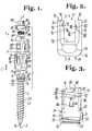
- FIG. 1is an enlarged, partial and exploded perspective view of a bone screw assembly according to the invention including a bone screw shank, a receiver, a lower compression insert and a closure structure having an outer fastener and an inner set screw and shown with a longitudinal connecting member in the form of a rod.
- FIG. 2is an enlarged front elevational view of the receiver of FIG. 1 .
- FIG. 3is an enlarged cross-sectional view taken along the line 3 - 3 of FIG. 1 .
- FIG. 4is an enlarged side elevational view of the receiver of FIG. 1 .
- FIG. 5is an enlarged cross-sectional view taken along the line 5 - 5 of FIG. 4 .
- FIG. 6is an enlarged top plan view of the receiver of FIG. 1 .
- FIG. 7is an enlarged side elevational view of the lower compression insert of FIG. 1 .
- FIG. 8is a cross-sectional view taken along the line 8 - 8 of FIG. 7 .
- FIG. 9is an enlarged top plan view of the lower compression insert of FIG. 1 .
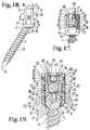
- FIG. 10is an enlarged and partial perspective view of the shank, receiver and compression insert of FIG. 1 , shown assembled.
- FIG. 11is a second enlarged and partial perspective view, similar to FIG. 10 .
- FIG. 12is an enlarged side elevational view of the closure structure of FIG. 1 .
- FIG. 13is an enlarged top plan view of the closure structure of FIG. 1 .
- FIG. 14is an enlarged top plan view of the set screw of the closure structure of FIG. 1 .
- FIG. 15is an enlarged and exploded front elevational view of the closure structure of FIG. 1 .
- FIG. 16is an enlarged perspective view of the closure structure of FIG. 1 with portions removed to show the detail thereof.
- FIG. 17is an enlarged and partial front elevational view of the assembly of FIG. 1 shown in a stage of assembly and with portions broken away to show the detail thereof.
- FIG. 18is an enlarged and partial side elevational view of the assembly of FIG. 1 shown fully assembled and with a break-off top removed.
- FIG. 19is a cross-sectional view taken along the line 19 - 19 of FIG. 18 .
- FIG. 20is an enlarged and partial perspective view of the assembly of FIG. 1 shown with a bar in lieu of the rod shown in FIG. 1 and with portions broken away to show the detail thereof.
- FIG. 21is an enlarged and partial front elevational view of the assembly shown in FIG. 20 .
- FIG. 22is an enlarged, partial and exploded perspective view of a second, alternative bone screw assembly according to the invention including a bone screw shank, a receiver, a retaining structure, a first lower compression insert, a second upper compression insert and a closure member and shown with a longitudinal connecting member in the form of a rod.
- FIG. 23is an enlarged front elevational view of the closure member of FIG. 22 .
- FIG. 24is a cross-sectional view taken along the line 24 - 24 of FIG. 23 .
- FIG. 25is an enlarged top plan view of the closure member of FIG. 23 .
- FIG. 26is an enlarged perspective view of the upper compression insert of FIG. 22 .
- FIG. 27is an enlarged front elevational view of the upper compression insert of FIG. 22 .
- FIG. 28is an enlarged side elevational view of the upper compression insert of FIG. 22 .
- FIG. 29is an enlarged and partial cross-sectional view of the closure member, similar to FIG. 24 and further showing the upper compression insert in front elevation prior to attachment to the closure member.
- FIG. 30is an enlarged and partial cross-sectional view of the closure member and front elevational view of the upper compression member, similar to FIG. 29 , showing the upper compression member rotatably attached to the closure member.
- FIG. 31is an enlarged front elevational view of the bone screw shank of FIG. 22 with portions broken away to show the detail thereof.
- FIG. 32is an enlarged front elevational view of the receiver and retaining structure of FIG. 22 with portions broken away to show the detail thereof and further showing the retaining structure in phantom in an early step of assembly of the bone screw assembly of FIG. 22 .
- FIG. 33is an enlarged and partial front elevational view of the receiver, the retaining structure and the bone screw shank of FIG. 22 with portions broken away to show the detail thereof and shown in a step of assembly subsequent to that shown in FIG. 32 .
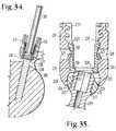
- FIG. 34is a reduced front elevational view of the receiver, the bone screw shank and the retaining structure of FIG. 22 with portions broken away to show the detail thereof and shown with a tool driving the bone screw shank into a vertebrae, also with portions broken away to show the detail thereof.
- FIG. 35is an enlarged and partial front elevational view of the receiver, bone screw shank, retaining structure and lower compression insert of FIG. 22 with portions broken away to show the detail thereof and shown with the rod illustrated in FIG. 22 , also with portions broken away to show the detail thereof.
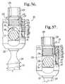
- FIG. 36is an enlarged and partial front elevational view of the assembly of FIG. 22 with portions broken away to show the detail thereof and further showing the upper compression insert and closure member partially inserted in the receiver.
- FIG. 37is an enlarged and partial front elevational view similar to FIG. 36 showing the upper compression insert and closure member fully seated in the receiver prior to removal of the closure member break-off head.
- FIG. 38is an enlarged and partial front elevational view of the assembly of FIG. 22 with portions broken away to show the detail thereof, and further showing the closure member break-off head removed.
- FIG. 39is an enlarged and partial front elevational view of an alternative embodiment according to the invention, similar to the assembly of FIG. 22 , but without the upper compression insert, shown assembled, with break-off top removed and with portions broken away to show the detail thereof and further showing the assembly cooperating with a longitudinal connecting member in the form of a bar of rectangular cross-section in lieu of the rod shown in FIG. 22 .
- FIG. 40is an enlarged and partial front elevational view of another embodiment according to the invention, similar to the assembly of FIG. 22 , but with a different compression insert, shown assembled with the break-off top removed, with portions broken away to show the detail thereof and further showing the assembly cooperating with a longitudinal connecting member in the form of a bar of rectangular cross-section.
- the reference number 1generally represents an embodiment of a polyaxial bone screw apparatus or assembly according to the present invention.
- the assembly 1includes a shank 4 that further includes a threaded body 6 integral with an upper portion 8 ; a receiver 10 ; a lower compression insert 12 ; and a dual closure structure, generally 14 .
- the shank 4 , receiver 10 , and compression insert 12are typically factory assembled prior to implantation of the shank body 6 into a vertebra (not shown). However, if desirable in certain situations, the shank may be implanted into a vertebra first and thereafter the receiver threadably connected thereto.
- the closure structure 14further includes an outer fastener 18 and an inner set screw 20 for engaging a longitudinal connecting member such as a rod 21 having a cylindrical surface 22 shown in FIGS. 1 and 17 - 19 , for example, or a longitudinal connecting member that does not have a circular cross-section, such as the bar 24 having a square or rectangular cross-section and planar surfaces 25 shown in FIGS. 20 and 21 .
- the outer fastener 18presses against the compression insert 12 that in turn presses upon the shank upper portion 8 which biases the portion 8 into fixed frictional contact with the receiver 10 , so as to fix the rod 21 or the bar 24 relative to the vertebra (not shown).
- the receiver 10 and the shank 4cooperate in such a manner that the receiver 10 and the shank 4 can be secured at any of a plurality of angles, articulations or rotational alignments relative to one another and within a selected range of angles both from side to side and from front to rear, to enable flexible or articulated engagement of the receiver 10 with respect to the shank 4 until both are locked or fixed relative to each other near the end of an implantation procedure.
- the rod 21 or the bar 24may be advantageously manipulated independently of locking the shank 4 with respect to the receiver 10 and then ultimately locked into place in the receiver 10 by rotation of the set screw 20 into direct engagement with the rod 21 or bar 24 .
- the rod 21 or the bar 24is made from a material such as rubber or PEEK, that exhibits any viscoelastic flow or creep, any resultant loosening of the rod 21 or the bar 24 with respect to the set screw 20 would have no impact on the security of the polyaxial locking of the shank 4 with respect to the receiver 10 provided by the pressure placed on the polyaxial mechanism by the outer fastener 18 through the insert 12 .
- the shank 4is elongate, with the shank body 6 having a helically wound bone implantable thread 28 extending from near a neck 30 located adjacent to the upper portion 8 to a tip 32 of the body 6 and extending radially outwardly therefrom.
- the body 6utilizing the thread 28 for gripping and advancement is implanted into the vertebra (not shown) leading with the tip 32 and driven down into the vertebra with an installation or driving tool, so as to be implanted in the vertebra to near the neck 30 , and as is described more fully in the paragraphs below.
- the shank 4has an elongate axis of rotation generally identified by the reference letter A.
- the neck 30extends axially upwardly from the shank body 6 .
- the neck 30is of slightly reduced radius as compared to an adjacent top 33 of the threaded body 6 .
- the shank upper portion 8that provides a connective or capture apparatus disposed at a distance from the threaded body top 33 and thus at a distance from the vertebra when the body 6 is implanted in the vertebra.
- the shank upper portion 8is configured for a polyaxial connection between the shank 4 and the receiver 10 and capturing the shank 4 upper portion 8 in the receiver 10 .
- the neck 30extends axially upwardly from the shank body 6 to a base 34 of the upper portion 8 .
- the upper portion 8has an outer partially spherically shaped surface 40 extending from the base 34 to a planar top portion 42 .
- Formed in the top portion 42is an internal drive mechanism 44 illustrated as a hex drive.
- the internal drive 44is coaxial with the shank 4 .
- the drive 44is sized and shaped for engagement with a driving tool (not shown) that is received by the drive 44 so as to form a socket and mating projection combination for both operably driving and rotating the shank body 6 into a vertebra.
- the illustrated base 34 of the portion 8has a smooth surface, but it is foreseen that the base 34 may have a high-friction or roughened surface, such as a scored or knurled surface.
- a helical guide and advancement structure 48Formed on the spherical surface 40 is a helical guide and advancement structure 48 .
- the guide and advancement structure 48retains the substantially spherical outer shape of the surface 40 at a crest thereof, but may be otherwise described as a substantially buttress thread form, sized and shaped to mate with a cooperating guide and advancement structure 50 disposed on an inner surface 52 of the receiver 10 disposed adjacent to and defining an opening 54 of a lower end or bottom 56 of the receiver 10 (see FIGS. 2 and 3 ).
- the guide and advancement structure 48is relatively thick and heavy to give strength to the thread and prevent the thread from being easily bent or deformed when axial pressure is applied to the shank 4 to maintain the upper portion 8 in the receiver 10 .
- the guide and advancement structure 48winds about the spherical surface 40 in a generally helical pattern or configuration that is typical of threads and can have various pitches, be clockwise or counterclockwise advanced, or vary in most of the ways that conventional buttress or square threads vary.
- the guide and advancement structure 48has a leading surface or flank 58 and a trailing surface or flank 59 .
- leading and trailingrefer to the direction of advancement of the upper portion 8 into the guide and advancement structure 50 of the receiver 10 aligning the axis A of the shank 4 with an elongate axis of rotation B of the receiver 10 and directing the upper portion 8 toward the receiver 10 , as shown by the straight arrow C illustrated in FIG. 1 .
- substantially buttress thread form 48is described herein, it is foreseen that other thread types, such as square threads, V-threads, inverted thread types, other thread-like or non-thread-like guide and advancement structures, such as flange form helically wound advancement structures may be utilized according to the invention.
- Advancement of the upper portion 8 into the receiver 10is accomplished by rotating the shank 4 in a clockwise or counterclockwise direction about the axes A and B and into the receiver 10 .
- a crest surface 60 connecting the leading surface 58 and the trailing surface 59is a loading surface after the upper portion 8 is fully disposed in the receiver 10 .
- the spherical surface 40 that includes the crest surface 60has an outer radius that is approximately equal to a radius of an inner seating surface of the receiver 10 , allowing for slidable mating contact between the surface 60 and the inner seating surface of the receiver 10 .
- An upper portion 62 of the spherical surface 40 located adjacent to the top planar surface 42is advantageously substantially spherical for sliding engagement and ultimate positive frictional mating engagement with the compression insert 12 , when the bone screw assembly 1 is assembled, as shown in FIG. 19 and in any alignment of the shank 4 relative to the receiver 10 .
- the surface 62is smooth. While not required in accordance with the practice of the invention, the surface 62 may be scored or knurled to further increase frictional positive mating engagement between the surface 62 and the compression insert 12 .
- the shank 4 shown in the drawingsis cannulated, having a small central bore 64 extending an entire length of the shank 4 along the axis A.
- the bore 64is defined by an inner cylindrical wall of the shank 4 and has a circular opening at the shank tip 32 and an upper opening communicating with the internal drive 44 .
- the bore 64provides a passage through the shank 4 interior for a length of wire (not shown) inserted into the vertebra (not shown) prior to the insertion of the shank body 6 , the wire providing a guide for insertion of the shank body 6 into the vertebra (not shown).
- the threaded shank body 6may be coated, perforated, made porous or otherwise treated.
- the treatmentmay include, but is not limited to a plasma spray coating or other type of coating of a metal or, for example, a calcium phosphate; or a roughening, perforation or indentation in the shank surface, such as by sputtering, sand blasting or acid etching, that allows for bony ingrowth or ongrowth.
- Certain metal coatingsact as a scaffold for bone ingrowth.
- Bio-ceramic calcium phosphate coatingsinclude, but are not limited to: alpha-tri-calcium phosphate and beta-tri-calcium phosphate (Ca 3 (PO 4 ) 2 , tetra-calcium phosphate (Ca 4 P 2 O 9 ), amorphous calcium phosphate and hydroxyapatite (Ca 10 (PO 4 ) 6 (OH) 2 ).
- Coating with hydroxyapatitefor example, is desirable as hydroxyapatite is chemically similar to bone with respect to mineral content and has been identified as being bioactive and thus not only supportive of bone ingrowth, but actively taking part in bone bonding.
- the receiver 10has a generally squared-off U-shaped appearance with a partially cylindrical inner profile and a substantially faceted outer profile; however, the outer profile could also be of another configuration, for example, curved or cylindrical.
- the receiver axis of rotation Bas shown in FIG. 1 , is aligned with the axis of rotation A of the shank 4 during assembly of the receiver 10 with the shank 4 and the insert 12 .
- the axis Bis typically disposed at an angle with respect to the axis A of the shank 4 .
- the receiver 10includes a base 70 integral with a pair of opposed substantially similar or identical upstanding opposed arms 72 and 72 ′ forming a squared-off U-shaped cradle and defining a channel 76 between the arms 72 and 72 ′ with an upper opening 77 and a lower seat 78 , the channel 76 sized and shaped for operably receiving the rod 21 or the bar 24 .
- Each of the arms 72 and 72 ′has an interior surface 80 and 80 ′, respectively, each having an inner cylindrical profile with opposed sloping interlocking flanged recesses or tracks 82 and 82 ′ configured to mate under rotation with a pair of opposed interlocking flange forms 84 and 84 ′ on the fastener 18 , as described more fully below.
- each track 82 and 82 ′run between and through pairs of parallel side surfaces 86 and 86 ′ of respective arms 72 and 72 ′.
- each track 82 and 82 ′is defined by a respective lower substantially planar surface 88 and 88 ′ running about the respective cylindrical interior surface 80 and 80 ′; a respective outer cylindrical surface 90 and 90 ′ running substantially parallel to the respective surfaces 80 and 80 ′, and a respective upper flanged portion 92 and 92 ′ also running about the respective interior surfaces 80 and 80 ′ and having a respective surface 94 and 94 ′ that extends downwardly (toward the base 70 ) and inwardly (toward the axis B) from the respective surface 90 and 90 ′.
- the tracks 82 and 82 ′are substantially identical in form and are located similarly on the respective arms 72 and 72 ′ with the exception that such tracks slope in opposite directions, each having a higher end disposed near a respective planar stepped or lower top surface portion 96 and 96 ′ of the respective arms 72 and 72 ′ and a lower end disposed near a respective planar upper top surface 98 and 98 ′ of the arms 72 and 72 ′.
- the respective lower surfaces 96 and 96 ′connected to respective upper surface 98 and 98 ′ by respective planar walls or stops 100 and 100 ′.
- the walls or stops 100 and 100 ′are each disposed parallel to the axis B.
- Opposed tool engaging apertures 105are formed on or through surfaces of the arms 72 and 72 ′ that may be used for holding the receiver 10 during assembly with the shank 4 and the retainer structure 12 and also during the implantation of the shank body 6 into a vertebra (not shown). It is foreseen that tool receiving grooves or apertures may be configured in a variety of shapes and sizes and be disposed at other locations on the receiver arms 72 and 72 ′.
- a pair of opposed spring tabs 106each having an upper body portion integral with a respective arm 72 or 72 ′, and a lower insert engaging surface 110 extending downwardly and inwardly from the respective upper body portion. The tabs 106 are generally directed towards the axis B and extend downwardly away from the guide tracks 82 and 82 ′.
- the lower end surfaces 110are thus positioned to engage the compression insert 12 and hold such insert in a desired position as will be described in greater detail below.
- the tabs 106are typically initially disposed parallel to the axis B and then a tool (not shown) is inserted into the aperture 105 from outside of the receiver 10 to engage and push the respective tab 106 , thereby bending the tab 106 inwardly in a direction toward the axis B until the tab 106 is at a desired angular position, such as is illustrated in FIG. 5 .
- Such bending of the tabs 106may be performed either prior to or after assembly of the receiver 10 with the shank 4 and the compression insert 12 .
- the tabs 106are bent inwardly prior to installation with the components 4 and 12 .
- the tabs 106may be machined or otherwise pre-fabricated to be angled or directed toward the axis B so as to engage the insert 12 as shown in the drawing figures.
- the illustrated tabs 106are resilient, having a spring-like nature. Thus, when operatively cooperating with the insert 12 , the tabs 106 bias against the insert 12 , holding such insert in a desired position; and yet the tabs 106 are flexible enough to allow a user to make desired adjustments of the position of the insert 12 within the receiver 10 .
- a chamber or cavity, generally 112communicating with and located beneath the channel 76 of the receiver 10 is a chamber or cavity, generally 112 , defined in part by an inner substantially cylindrical surface 114 and also the lower internal surface 52 previously described herein that includes the guide and advancement structure 50 and also includes a substantially spherical seating surface portion 116 .
- the cylindrical surface 114 that defines a portion of the cavity 112opens upwardly into the channel 76 .
- the inner surface 116 that is located below the surface 114is sized and shaped for mating with the shank upper portion 8 spherical surface 40 that includes the crest surfaces 60 .
- the surface portion 116is part of the inner surface 52 that includes the opening 54 .
- the opening 54communicates with both the cavity 112 and the receiver lower exterior or bottom 56 of the base 70 .
- the opening 54is substantially coaxially aligned with respect to the rotational axis B of the receiver 10 .
- the opening 54is also sized and shaped to be smaller than an outer radial dimension of the shank upper portion 8 after the portion 8 has been threadably rotated through the opening 54 , so as to form a restriction to prevent the portion 8 from passing through the cavity 112 and out into the lower exterior 56 of the receiver 10 during operation thereof.
- the compression insert 12is sized and shaped to be received by and downloaded into the receiver 10 through the opening 77 .
- a portion of the insert 12is disposed between the rod 21 or the bar 24 and the upper portion 8 of the bone screw 4 as illustrated, for example, in FIG. 19 .
- the closure structure 14 outer fastener 18presses directly upon the insert 12 that in turn presses upon the shank upper portion 8 , pressing the upper portion 8 against the seating surface portion 116 of the receiver 10 , resulting in frictional engagement and locking of the angular position of the bone screw shank 4 with respect to the receiver 10 while allowing for further manipulation of the rod 21 or bar 24 until such rod or bar is locked into place by engagement with the inner set screw 20 .
- the compression insert 12has an operational central axis D that is the same as the central axis B of the receiver 10 .
- the compression insert 12has a central channel or through bore substantially defined by an inner cylindrical surface 120 and an inner partially spherical surface 122 , both having the central axis D.
- the compression insert 12 through boreis sized and shaped to receive a driving tool (not shown) therethrough that engages the shank drive feature 44 when the shank body 6 is driven into bone.
- the surface 122is sized and shaped to cooperate with the spherical surface 62 of the shank upper portion 8 such that the surface 122 slidingly and pivotally mates with the spherical surface 62 .
- the surface 122may include a roughening or surface finish to aid in frictional contact between the surface 122 and the surface 62 , once a desired angle of articulation of the shank 4 with respect to the receiver 10 is reached.
- the compression insert 12also includes a pair of arms 124 with a squared-off U-shaped surface or saddle 126 formed therebetween.
- the saddle 126defines a channel that communicates with the bore defined by the cylindrical surface 120 and the spherical surface 122 .
- the saddle 126is substantially defined by a pair of planar opposed parallel surfaces 128 and a planar bottom or seating surface 130 , the surfaces 128 and 130 being sized and shaped to closely receive the cylindrical rod 21 or the bar 24 planar surfaces 25 .
- the saddle 126extends from top surfaces 132 to the bottom seating surface 130 .
- a base having an outer cylindrical surface 134is disposed between the saddle 126 and an annular bottom surface 135 .
- the cylindrical surface 134also extends about the arms 124 .
- a shallow groove 136Formed in the surface 124 and located centrally with respect to each arm 124 outer cylindrical surface is a shallow groove 136 having a substantially flat surface.
- a surface portion 137 disposed adjacent to each groove 136 and located between such groove 136 and the bottom surface 135includes a plurality of ridges or other roughened surface features.
- the grooves 136are sized and shaped to cooperate with the tabs 106 of the receiver 10 as will be described in greater detail below.
- the roughened surface portions 137further cooperate with the tabs 106 to frictionally check or otherwise prohibit relative movement between the tabs 106 and such surfaces 137 during assembly and operation of the assembly 1 .
- the grooves 136may be of any shape, but are preferably elongate with the flat surface running parallel to the axis D and having a width that receives the respective tab 106 .
- the illustrated bottom surface 135is substantially planar and annular and disposed perpendicular to the axis D.
- Formed on the planar side surfaces 128 and also formed into the top surface 132are a pair of opposed recesses 138 , each recess having a cylindrical surface 140 running parallel to the axis D and a planar bottom surface 141 disposed perpendicular to the axis D.
- the recesses 138are sized and shaped to provide clearance for the inner set screw 20 of the closure structure 14 as the set screw 20 is rotated down into engagement with the rod 21 or the bar 24 as will be described in greater detail below.
- the compression or pressure insert 12ultimately seats on the shank upper portion 8 and is disposed substantially in the upper cylindrical portion 114 of the cavity 112 , with the tabs 106 engaging the insert 12 at the grooves 136 , thereby holding the insert 12 in a desired alignment within the receiver 10 as will be described in greater detail below.
- the insert 12extends at least partially into the receiver channel 76 such that the saddle 126 surface substantially contacts and engages the outer surface 22 of the rod 21 (or one of the planar surfaces 25 of the bar 24 ) when such rod or bar is placed in the receiver 10 , keeping the rod or bar in spaced relation with the receiver 10 lower seating surface 78 .
- FIGS. 1 and 12 - 16illustrate the nested closure structure or closure top 14 that includes the outer fastener 18 and the uploaded inner set screw 20 that are coaxial along a central axis E that in operation is the same as the axis B of the receiver 10 .
- the fastener 18further includes a base 146 integral or otherwise attached to a break-off head 148 .
- the base 146cooperates with the receiver 10 to capture the rod 21 or the bar 24 (or any other longitudinal connecting member) within the bone screw receiver 10 .
- the break-off installation head 148is in the form of a hex-shaped external drive feature having six planar surfaces 150 sized and shaped for engagement with a socket tool (not shown) for installing the fastener 14 to the bone screw receiver 10 and thereafter separating the break-off head 148 from the respective base 146 when installation torque exceeds selected levels.
- a through slot 151 formed in a top surface 152 of the break-off head 148 and disposed perpendicular to the axis Emay also be utilized to manipulate and/or rotate the closure 14 .
- a through-bore 154extends along the axis E completely through the fastener 18 from the top surface 152 of the break-off head 148 to a bottom surface 156 of the base 146 . As illustrated in FIG. 13 , the portion of the bore 154 running through the break-off head 148 is sized and shaped to receive and provide some clearance around a tool (not shown) engaging an inner drive 158 of the inner set screw 20 .
- the base 146 of the fastener 18is substantially cylindrical, having an external surface 160 .
- the flange forms 84 and 84 ′project substantially radially and oppositely from the surface 160 near the bottom surface 156 .
- a pair of opposed substantially flat wing members 164 and 164 ′also extend radially from the surface 160 and are located near a top surface 166 of the base 146 .
- the flanges 84 and 84 ′are sized and shaped to slidingly mate with respective lower surfaces 88 and 88 ′, cylindrical surfaces 90 and 90 ′ and flanged portions 92 and 92 ′ of the respective tracks 82 and 82 ′ of the receiver 10 .
- the wing members 164 and 164 ′are plate-like with upper and lower parallel substantially planar surfaces.
- the wing members 164 and 164 ′are sized and shaped to slidingly mate with respective step surfaces 96 and 96 ′ of the receiver 10 and abut against respective surfaces 100 and 100 ′ when the flanges 84 and 84 ′ are rotated into a final fixed frictional engagement with respective tracks 82 and 82 ′ as illustrated, for example, in FIGS. 19 and 20 .
- the bore 154is substantially defined by a guide and advancement structure shown in the drawing figures as an internal V-shaped thread 176 .
- the thread 176is sized and shaped to receive the threaded set screw 20 therein as will be discussed in more detail below.
- a traditional V-shaped thread 176is shown, it is foreseen that other types of helical guide and advancement structures may be used.
- an abutment shoulder 178Near a top of the base 146 , an abutment shoulder 178 , extends uniformly radially inwardly. The abutment shoulder 178 is spaced from the V-shaped thread 176 and sized and shaped to be a stop for the set screw 20 , prohibiting the set screw 20 from advancing upwardly out of the base 146 .
- the set screwmay be equipped with an outwardly extending abutment feature near a base thereof, with complimentary alterations made in the fastener base 146 , such that the set screw 20 would be prohibited from advancing upwardly out of the top of the base 146 due to abutment of such outwardly extending feature against a surface of the base 146 .
- An inner cylindrical wall 180separates the abutment shoulder 178 from the thread 176 .
- the cylindrical wall 180has a diameter equal to or slightly greater than a root or major diameter of the internal thread 176 .
- the wall 180partially defines a cylindrical space or passage for axial adjustable placement of the screw 20 with respect to the longitudinal connecting member 21 or 24 .
- the fastener break-off head 148is integral or otherwise attached to the fastener base 146 at a neck or weakened region 182 .
- the neck 182is dimensioned in thickness to control the torque at which the break-off head 148 separates from the fastener base 146 .
- the preselected separation torque of the neck 182is designed to provide secure engagement between the fastener base 146 and the lower compression insert 12 that in turn presses against the shank upper portion 8 , clamping the shank 4 in a desired angular orientation with respect to the receiver 10 .
- the fastener 18captures the longitudinal connecting member 21 or 24 within the receiver 10 before the head 148 separates, by abutting against the lower compression insert 12 without making contact with the rod 21 or the bar 24 .
- 120 inch pounds of forcemay be a selected break-off torque to lock the bone screw shank in place without placing any pressure on the rod 21 or the bar 24 .
- Separation of the break-off head 148leaves only the more compact base 146 of the fastener 18 installed in the bone screw receiver 10 , so that the installed fastener 18 has a low profile.
- the set screw 20may then be rotated and moved downwardly into secure engagement with the rod 21 or the bar 24 .
- the uploadable set screw 20has a substantially annular and planar top 186 and a substantially annular and planar bottom 187 .
- the screw 20is substantially cylindrical in shape and coaxial with the fastener 18 .
- the screw 20includes an outer threaded cylindrical surface 188 extending from the top 186 to the bottom surface 187 .
- the v-shape thread of the surface 188is sized and shaped to be received by and mated with the inner thread 176 of the fastener base 146 in a nested, coaxial relationship.
- the set screw 20includes a central aperture or drive 190 formed in the top 186 and sized and shaped for a positive, non-slip engagement by a set screw installment and removal tool (not shown) that may be inserted through the bore 154 of the fastener 18 and then into the drive aperture 190 .
- the central set screw aperture 190cooperates with the central internal bore 154 of the fastener 18 for accessing and uploading the set screw 20 into the fastener 18 prior to engagement with the bone screw receiver 10 .
- the set screw 20is rotated by a tool engaging the drive feature 190 to place the set screw bottom 187 into frictional engagement with the rod 21 or the bar 24 .
- Such frictional engagementis therefore readily controllable by a surgeon so that rod 21 or the bar 24 may be readily manipulated until late in the surgery, if desired.
- the set screw 20may be rotated to drive the screw 20 into fixed frictional engagement with the rod 21 or the bar 24 without varying the angular relationship between the receiver 10 and the bone screw shank 4 .
- the set screw 20may further include a cannulation through bore extending along a central axis thereof for providing a passage through the closure 14 interior for a length of wire (not shown) inserted therein to provide a guide for insertion of the closure top into the receiver arms 72 and 72 ′.
- the elongate longitudinal connecting member that are illustrated in this applicationinclude the cylindrical rod 21 and the bar 24 of square or other rectangular cross-section. A variety of shapes are possible, including but not limited to rods or bars of oval or other curved or polygonal cross-section.
- the rod 21 or bar 24may be a component of a dynamic stabilization connecting member, with the cylindrical or bar-shaped portions sized and shaped for being received by the insert saddle 126 also being integral or otherwise fixed to a more flexible, bendable or damping component that extends between adjacent pairs of bone screw assemblies 1 .
- Such a rod or bar componentmay be made from a variety of materials including metal, metal alloys or other suitable materials, including, but not limited to plastic polymers such as polyetheretherketone (PEEK), ultra-high-molecular weight-polyethylene (UHMWP), polyurethanes and composites, including composites containing carbon fiber, as well as resorbable materials, such as polylactic acids.
- plastic polymerssuch as polyetheretherketone (PEEK), ultra-high-molecular weight-polyethylene (UHMWP), polyurethanes and composites, including composites containing carbon fiber, as well as resorbable materials, such as polylactic acids.
- the shank upper portionis pre-loaded by insertion or bottom-loading into the receiver 10 through the opening 54 .
- the upper portion 8is aligned with the receiver 10 , with the axes A and B aligned so that the buttress thread 48 of the upper portion 8 is inserted into and rotatingly mated with the guide and advancement structure 50 on the receiver 10 .
- the shank 4is rotated in a clockwise or counter-clockwise direction to fully mate the structures 48 and 50 , and the rotation is continued until the thread 48 disengages from the thread 50 and the upper portion 8 is fully disposed in the receiver cavity 112 .
- the shank upper portion 8is thus in a slidable and rotatable engagement with the receiver 10 , while the upper portion 8 is maintained in the receiver 10 with the shank body 6 in pivotal or swivelable relation with the receiver 10 .
- the shank body 6can be pivoted or rotated through a substantial angular rotation relative to the receiver 10 , both from side to side and from front to rear so as to substantially provide a universal or ball joint.
- the discontinuous spherical surface 40 defined by the crest surface 60is in slidable engagement with the receiver spherical seating surface 116 .
- the compression or pressure insert 12is then inserted or top loaded into the upper opening 77 of the channel 76 of the receiver 10 with the bottom surface 135 facing the top surface 42 of the shank upper portion 8 and the arms 124 aligned with the arms 72 and 72 ′ of the receiver 10 .
- the tabs 106are received in respective grooves 136 .
- the tabs 106press against the insert 12 at the grooves 136 , allowing for some upward and downward adjustment of the insert 12 .
- the bone screw with assembled insert 12(as shown in FIGS. 10 and 11 ) is typically screwed into a bone, such as a vertebra (not shown), by rotation of the shank 4 using a driving tool (not shown) that operably drives and rotates the shank 4 by engagement thereof with the internal drive 44 .
- the vertebra (not shown)may be pre-drilled to minimize stressing the bone and have a guide wire (not shown) that is shaped for the cannula 64 and inserted to provide a guide for the placement and angle of the shank 4 with respect to the vertebra.
- a further tap holemay be made using a tap with the guide wire as a guide.
- the assembly 1is threaded onto the guide wire utilizing the cannulation bore 64 by first threading the wire into the bottom opening 32 and then out of the top at the internal drive 44 .
- the shank 4is then driven into the vertebra, using the wire as a placement guide.
- the set screw 20is inserted into the base 146 of the outer fastener 18 at the bore 154 that opens to the bottom surface 156 .
- the screw 20is rotated and drawn upwardly toward the top surface 166 of the base 146 , mating the threaded surface 188 with the fastener inner thread 176 .
- the screw 20is rotated until the screw 20 is disposed entirely within the fastener 18 with the top surface 186 of the screw 20 being closely adjacent to or in contact with the abutment shoulder 178 as illustrated in FIG. 16 .
- the rod 21 or other longitudinal connecting membersuch as the bar 24 shown in FIGS. 20 and 21
- the closure structure 14is then inserted into the receiver 10 by placing the flange forms 84 and 84 ′ between the arms 72 and 72 ′ followed by aligning the forms 84 and 84 ′ with the respective tracks 82 and 82 ′ of the receiver 10 .
- Such alignmentalso aligns the opposed wing members 164 and 164 ′ with the respective upper step surfaces 96 and 96 ′.
- the closure structureis then rotated about the axis B to mate the flange forms 84 and 84 ′ with the tracks 82 and 82 ′. Alignment of the rod surface 22 or the bar surfaces 25 with respect to the receiver channel 76 and the saddle 126 of the insert 14 is initially provided and then maintained by pressure placed at the insert grooves 136 by the tabs 106 .
- the closure fastener 14is rotated, using a tool engaged with the break-off head 148 hex drive 150 until a selected pressure is reached at which point the head 148 separates from the fastener base 146 . Also with reference to FIG. 17 , at this time, the set screw 20 is still entirely disposed within the base 146 and does not engage the rod 21 or the bar 24 .
- the outer fastener 18is in engagement with the insert 12 at the top surface 132 of the arms 124 , placing the insert 12 surface 122 into frictional engagement with the surface 62 of the shank upper portion 8 that in turn places the upper portion 8 into frictional engagement with the surface 116 of the receiver 10 , locking the shank 4 with respect to the receiver 10 in a desired angle with respect thereto.
- about 80 to about 120 inch pounds pressuremay be required for removing the break-off head 148 and fixing the bone screw shank 4 with respect to the receiver 10 .
- the rod 21(or bar 24 ) is eventually locked into place by utilizing a tool (not shown) inserted into the bore 154 and into engagement with the set screw inner drive 158 .
- the toolis used to rotate the set screw 20 and drive the screw 20 downwardly until the surface 187 is in frictional engagement with the rod 21 surface 22 (or the bar 24 surface 25 ).
- the screw 20advances downwardly toward the rod surface 22 , the screw 20 remains in spaced relation with the insert 12 with the recessed portions 138 of the insert 12 providing clearance for such downward advancement of the screw 20 .
- the screw 20does not make contact with any portion of the insert 12 .
- FIGS. 20 and 21also illustrate that the set screw 20 may be rotated and driven downwardly into contact with the bar 24 (or the rod 21 ), if desired, prior to final torquing of the fastener 14 and removal of the break-off head 148 .
- the dual closure 14advantageously allows for the use with a variety of longitudinal members made from a wide range of materials.
- the assembly 1advantageously cooperates with both cylindrical rods and with bars of square or rectangular cross-section, such as the bar 24 of substantially square cross-section.
- the bar 24 made from PEEK, for example,provides for some dynamic, flexible support and yet due to the geometry thereof provides greater support with respect to torsional forces, for example, than would a cylindrical PEEK rod.
- the squared-off channel provided by the insert 12allows for the easy substitution of connecting members of round, square, rectangular or other cross-sectional shape.
- a second pressure insertmay be located between the set screw 20 and the rod 21 or bar 24 .
- the rod 21 or the bar 24may include a central through bore or lumen (not shown) allowing for threading of such rod or bar and implantation in a percutaneous or less invasive procedure.
- the reference numeral 201generally designates an alternative polyaxial bone screw assembly according to the invention for use with the rod 21 or the bar 24 previously described herein with respect to the assembly 1 and also with a variety of rigid or dynamic stabilization longitudinal connecting member assemblies.
- the bone screw assembly 201is substantially similar to the bone screw assembly 401 disclosed in Applicant's US Patent Publication No. 2007/0055244, published Mar. 8, 2007 (U.S. patent application Ser. No. 11/522,503 filed Sep. 14, 2006) and incorporated by reference herein (hereafter the '244 publication) and illustrated in FIGS. 22-34 therein.
- the bone screw assembly 201 of the present inventionincludes a shank 204 that further includes a body 206 integral with an upwardly extending, substantially cylindrical upper portion or capture structure 208 operationally disposed primarily within a receiver 210 .
- the shank 204is similar to the shank 414 disclosed in the '244 publication in that the body 206 includes a helical thread 211 for attachment to a vertebrae.
- the assembly 201further includes a retainer in the form of a retaining and articulating structure 212 that is similar but not identical to the retainer disclosed in the '244 publication.
- the shank upper portion 208also includes a substantially spherically shaped upper or top surface 213 sized and shaped to slidingly mate with a lower spherical surface of a lower pressure insert 214 . Therefore, unlike the bone screw disclosed in the '244 publication, the pressure insert 214 operationally presses directly against the shank upper portion 208 and not the retainer 212 .
- the shank 204 , the receiver 210 , the retaining and articulating structure 212 and the first or lower compression insert 214are preferably assembled prior to implantation of the shank body 206 into a vertebra.
- the shank bodymay include a cannulation bore 264 similar in form and function to the bore 64 of the shank 4 of the assembly 1 .
- the shank upper portion 208further includes a substantially cylindrical portion 215 having a helical thread 216 thereon, the portion 215 disposed adjacent to the spherical surface 213 and extending along an axial length thereof.
- the threaded cylindrical portion 215flares or widens outwardly near an end 217 thereof into a portion 218 of slightly greater diameter than a remainder of the cylindrical portion 215 .
- the thread 216 or other helically wound guide and advancement structureis sized and shaped to mate with an inner portion 220 of the retainer 212 having a thread 221 or other helically wound guide and advancement structure.
- the upper portion 208further includes a top surface 222 having an internal drive 223 formed therein for engaging with a driving tool (not shown) for rotating the shank 204 and driving the shank 204 into a vertebra (not shown).
- a driving toolnot shown
- an outer substantially spherical surface 224 of the retainer 212is in sliding engagement with an inner substantially spherical seating surface 228 of the receiver 210 as described previously herein with respect to the upper portion 8 and the seating surface 116 of the assembly 1 .
- the retainer 212further includes a sloped or frusto-conical top surface 225 located between the inner threaded surface 220 and the outer spherical surface 224 .
- the top surface 225may be planar.
- the sloped surface 225advantageously provides for additional clearance between the retainer 212 and the lower pressure insert 214 , ensuring that the insert 214 engages only the bone screw shank at the surface 213 and not any portion of the retainer 212 .
- the assembly 201further includes an upper insert 226 and a closure structure, generally 230 , having an outer fastener 232 and an uploaded inner set screw 234 .
- the outer fastener 232includes a base 236 integral or otherwise attached to a break-off head 238 .
- the base 236cooperates with the receiver 210 to capture the rod 21 or the bar 24 within the bone screw receiver 210 .
- the break-off installation head 238includes an internal drive or aperture 240 sized and shaped for engagement with a tool (not shown) for installing the fastener 232 to the bone screw receiver 210 and thereafter separating the break-off head 238 from a respective base 236 when installation torque exceeds selected levels.
- the base 236 of the fastener portion 232is substantially cylindrical, having an axis of rotation G and an external surface 250 having a guide and advancement structure 252 disposed thereon.
- the guide and advancement structure 252is matingly attachable to a guide and advancement structure 253 of the bone screw receiver 210 .
- the cooperating guide and advancement structures 252 and 253can be of a variety of types, including, but not limited to buttress threads, reverse angle threads, or square threads, and are preferably helically wound flange forms that interlock and are splay resistant, and thus do not exert radially outward forces on the arms of the receiver 210 , thereby avoiding tendencies toward splaying of the receiver arms when the fastener portion 232 is tightly torqued into the receiver 210 .
- the fastener portion 232includes an internal, centrally located bore 254 .
- the bore 254is substantially defined by a guide and advancement structure, shown in FIG. 24 as an internal V-shaped thread 256 .
- the thread 256is sized and shaped to receive the threaded set screw 234 therein as will be discussed in more detail below.
- a traditional V-shaped thread 256is shown, it is foreseen that other types of helical guide and advancement structures may be used.
- an abutment shoulder 260Near a top of the base 236 , an abutment shoulder 260 , extends uniformly radially inwardly.
- the abutment shoulder 260is spaced from the V-shaped thread 256 and sized and shaped to be a stop for the set screw 234 , prohibiting the set screw 234 from advancing upwardly out of the base 236 .
- the set screwmay be equipped with an outwardly extending abutment feature near a base thereof, with complimentary alterations made in the fastener base 236 , such that the set screw 234 would be prohibited from advancing upwardly out of the top of the base 236 due to abutment of such outwardly extending feature against a surface of the base 236 .
- An inner cylindrical wall 262separates the abutment shoulder 260 from the thread 256 .
- the cylindrical wall 262has a diameter equal to or slightly greater than a root or major diameter of the internal thread 256 .
- the wall 262partially defines a cylindrical space or passage 264 for axial adjustable placement of the screw 234 with respect to the longitudinal connecting member 21 or 24 .
- the fastener break-off head 238is integral or otherwise attached to the fastener 232 at a neck or weakened region 266 .
- the neck 266is dimensioned in thickness to control the torque at which the break-off head 238 separates from the fastener 232 .
- the preselected separation torque of the neck 266is designed to provide secure engagement between the fastener 232 and the lower compression structure or insert 214 that in turn presses directly against the shank upper portion 208 that is threadably mated to the retainer 212 , pressing the retainer 212 against the receiver 210 and thus clamping the shank 204 in a desired angular orientation with respect to the receiver 210 and the rod 21 or the bar 24 .
- the fastener 232thus captures the longitudinal connecting member 21 or 24 within the receiver 210 before the head 238 separates, by abutting against the lower compression member 214 without making contact with the rod 21 or the bar 24 .
- 120 inch pounds of forcemay be a selected break-off torque to lock the bone screw shank in place without placing any pressure on the rod 21 or the bar 24 .
- the illustrated internal driving feature 240 of the break-off head 238enables positive, non-slip engagement of the head 238 by an installation and torquing tool. Separation of the break-off head 238 leaves only the more compact base 236 of the fastener 232 installed in the bone screw receiver 210 , so that the installed fastener 232 has a low profile. As will be described in greater detail below, the set screw 234 may then be rotated and moved downwardly into secure engagement with the rod 21 or the bar 24 .
- the base 236 of the fastener 232includes a planar bottom surface 268 disposed substantially perpendicular to the axis G for abutting the top surfaces 269 of arms of the compression insert 214 .
- the bottom surfacemay also be ramped or inclined as described in the '244 publication (with cooperating ramped surface on the insert 214 ).
- the uploadable set screw 234has a substantially annular and planar top 276 and a substantially annular and planar bottom 277 .
- the screw 234is substantially cylindrical in shape and coaxial with the fastener 232 .
- the screw 234includes an outer cylindrical surface 278 disposed near the bottom 277 and a threaded surface 280 extending from the top 276 to the cylindrical surface 278 .
- the v-shaped thread 280is sized and shaped to be received by and mated with the inner thread 256 of the fastener base 236 in a nested, coaxial relationship.
- the set screw 234includes a central aperture 286 formed in the top 276 and defined by side walls 288 that define a driving feature similar to but of smaller dimensions than the driving feature 240 of the fastener 232 .
- the driving featurefurther includes a seating surface or bottom 289 , aiding in a positive, non-slip engagement by a set screw installment and removal tool (not shown) that may be inserted through the aperture formed by the driving feature 240 of the fastener 232 and then into the aperture 286 and into engagement with the walls 288 defining the set screw driving feature.
- a lower central aperture or bore 290extends between the central aperture 286 and the bottom 277 of the set screw 234 .
- the bore 290is sized and shaped to receive and hold an upper portion of the upper compression structure 226 as will be described more fully below.
- the central set screw aperture 286cooperates with the central internal bore 254 of the fastener 232 for accessing and uploading the set screw 234 into the fastener 232 prior to engagement with the bone screw receiver 220 .
- the set screw 234is rotated by a tool engaging the drive feature walls 288 to place the set screw bottom 277 into frictional engagement with the rod 21 or bar 24 .
- the longitudinal connecting member 21 or 24there are circumstances under which it is desirable or necessary to release the longitudinal connecting member 21 or 24 from the bone screw assembly 201 .
- the tool that engages and rotates the set screw 234 at the driving feature 288may be used to remove both the set screw 234 and attached fastener base 236 as a single unit, with the set screw 234 contacting and contained within the base 236 by the abutment shoulder 260 .
- the lower compression insert 214includes a substantially cylindrical body 310 integral with a pair of upstanding arms 312 .
- the body 310 and arms 312form a generally squared-off U-shaped, open, through-channel 314 with planar side surfaces 315 disposed perpendicular to a planar bottom seating surface 316 , the channel 314 and seating surface 316 sized and shaped to receive either the rod 21 or the planar surfaces 25 of the bar 24 .
- the channel surfaces 315do not closely receive the rod 21 and as will be described below, the rod 21 is held substantially centrally in place by the upper compression insert 226 .
- the lower insertmay be sized and shaped to closely receive the rod 21 as well as the bar 24 as shown in FIG. 34 .
- the arms 312 of the inert 214 disposed on either side of the channel 314each include a top flanged portion 318 , each portion 318 including the planar top surface 269 previously described herein, sized and shaped to engage the surface 268 of the fastener 232 .
- the compression insert 214further includes a bottom surface 320 and a substantially cylindrical outer surface 322 .
- An inner cylindrical wall 324 defining a central through-boreextends along a central axis of the compression structure 214 and extends between the seating surface 316 and a substantially spherical surface 326 .
- the surface 326extends between the inner cylindrical wall 324 and the bottom surface 320 .
- the surface 326is substantially similar to the spherical surface 122 of the compression insert 12 previously described herein, the surface 326 being sized and shaped to frictionally engage and mate with the upper spherical surface 213 of the shank upper portion 208 .
- the cylindrical surface 322has an outer diameter slightly smaller than a diameter between crests of the guide and advancement structure 253 of the receiver 210 allowing for top loading of the compression insert 214 .
- the top surface portions 318 disposed on each of the upstanding arms 312are inserted into the channel between the receiver 210 upstanding arms and then the insert 214 is rotated about the axis F with the portion 318 sized and shaped to be received into a run-out or recess located beneath the guide and advancement structure 253 .
- the receiver 210fully receives the lower compression insert 214 and blocks the insert 214 from spreading or splaying in any direction.
- the through-channel 314is sized and shaped such that the upper compression structure or insert 226 is receivable in the channel 314 between opposed upper substantially planar walls 315 that define the channel 314 from the base 316 to the top surfaces 269 . Adequate clearance is provided such that the upper compression insert 226 is in slightly spaced or in sliding relationship with the walls 315 , allowing for independent movement of the upper compression insert 226 with respect to the lower compression insert 214 .
- the lower insert 214further includes opposed grooves 328 formed on outer surfaces of the arms 312 .
- the grooves 328are substantially similar in form and function to the grooves 136 of the insert 12 of the assembly 1 .
- the grooves 328are sized and shaped to receive spring tabs 329 of the receiver 210 .
- the spring tabs 329are similar in form and function to the tabs 106 previously described herein with respect to the receiver 10 of the assembly 1 with the exception that the spring tabs 329 extend from a lower portion of the receiver 210 in a direction upwardly toward the guide and advancement structure 253 as well as inwardly toward the axis F of the receiver 210 .
- the upper or second compression structure or insert 226includes a body 330 having a pair of downwardly extending legs 332 .
- the body 330 and the legs 332form a generally U-shaped, open, through-channel having a substantially U-shaped seating surface 336 having a radius substantially conforming to the outer radius of the rod 21 and thus configured to operably snugly engage the rod 21 at the external surface 22 thereof opposite the seating surface 316 of the lower compression insert 214 .
- FIG. 40illustrates an alternative embodiment wherein an upper insert 226 ′ includes a planar bottom surface 338 ′ for engaging a planar top surface 25 ′ of a bar 24 ′.
- polyaxial bone screw shank 204 and cooperating threaded retainer 212 capture connection provided in the assembly 201may also be used without an upper pressure insert and in combination with the dual closure structure 14 of the assembly 1 , or alternatively, with a one-piece closure assembly.
- the legs 332each include a bottom surface 338 that is substantially parallel to a planar top surface 340 .
- the compression insert 226includes a pair of opposed curved outer surfaces 342 substantially perpendicular to the top surface 340 and extending between the top surface 340 and the seating surface 336 .
- the curved surfaces 342further extend along the legs 332 and terminate at the bottom surfaces 338 .
- a pair of opposed substantially planar outer surfaces 343are disposed between the curved surfaces 342 and are also disposed substantially perpendicular to the top surface 340 , each planar surface 343 extending between the top surface 340 and a respective bottom surface 338 .
- a pin 344 of substantially circular cross sectionis disposed centrally on the top surface 340 and extends upwardly therefrom, being sized and shaped to fit within the centrally located lower bore 290 formed in the set screw 234 .
- the pin 344further includes a substantially cylindrical base 346 and a U-shaped channel 348 formed by a pair of opposed, flanged arms 350 that extend from the base 346 upwardly and substantially parallel to one another.
- Each of the flanged armsincludes a partially conical surface portion 351 and a flat bottom surface 352 that is substantially parallel to the top planar surface 340 of the compression structure body 330 . As illustrated in FIGS.
- the pin 344is receivable in the bore 240 with surfaces forming the bore pressing and deforming the flanged arms 350 toward one another as the upper compression structure 226 is pressed against the set screw 234 that has already been up-loaded into a fastener portion 232 .
- the conical surface portions 351clear the bore 240 and enter the set screw aperture 286 , the flanged arms 350 return to the original upright and substantially parallel form with the surfaces 352 being in contact with and seated upon a portion of the bottom surface 289 as illustrated in FIG. 30 .
- the flanged arms 350thus keep the compression structure 226 attached to the set screw 234 and yet rotatable with respect thereto about an axis of rotation H of the cylindrical base 346 of the structure that is coaxial with the axis G of the set screw 234 and fastener 232 , providing a centered relationship between the closure structure 230 and the compression structure 226 while allowing the compression structure 226 to freely rotate into a position centered over and in gripping engagement with the longitudinal connecting member 21 when assembled thereon. Furthermore, if removal of the fastener and uploaded set screw is desired, the attached compression structure 226 is advantageously removed along therewith.
- the set screw 234is assembled with the fastener 232 by inserting a set screw tool (not shown) through the bore 254 of the fastener 232 and into the aperture 286 of the set screw 234 , with outer features of the tool engaging the inner walls 288 of the set screw 234 .
- the set screw 234is then uploaded into the fastener 232 by rotation of the set screw 234 with respect to the fastener 232 to mate the set screw thread 280 with the fastener inner thread 256 until the set screw top surface 276 is spaced from the abutment shoulder 260 , but substantially nested in the fastener 232 , with possibly only the cylindrical surface 278 extending from the fastener base 236 .
- the upper compression structure 224is then attached to the set screw 234 as previously described with the pin 344 being received by the bore 290 and inserted therethrough until the arms 350 are disposed within the aperture 286 , with the lower surfaces 352 of the flanged arms seated on the bottom 289 of the set screw aperture 286 , capturing the flanged arms 350 within the aperture 286 .
- the nested assembly shown in FIG. 24 and attached to an upper compression structure as shown in FIGS. 29 and 30is now pre-assembled and ready for use with a bone screw receiver 210 and cooperating rod 21 .
- the retainer 212is typically first inserted or top-loaded, into the receiver squared-off U-shaped channel and then into the receiver cavity. Then, the retainer 212 is rotated approximately 90 degrees so as to be coaxial with the receiver 210 axis F and then seated in sliding engagement with the inner seating surface of the receiver 210 as shown in FIG. 32 . With reference to FIG. 33 , the shank upper portion 208 is then inserted or bottom-loaded into the receiver 210 .
- the retainer 212now disposed in the receiver 210 is coaxially aligned with the shank 204 and the upper portion 208 is generally rotated about the axis F mating the threaded surface 215 with the threaded surface 220 of the retainer 212 . Rotation continues until the retainer 212 engages the flared portion 218 and is tightened thereon, fixing the retainer 212 to the shank upper portion 208 as shown, for example, in FIG. 35 .
- the shank 204 and or the retainer 212are rotated to fully mate such structures at a factory setting that includes tooling for holding and precisely rotating the shank 204 and/or the retainer 212 until locking frictional engagement therebetween is accomplished.
- both the shank 204 and the retainer 212are in rotatable and swivelable engagement with the receiver 210 , while the shank upper portion 208 and the lower aperture or neck of the receiver 210 cooperate to maintain the shank body 206 in swivelable relation with the receiver 210 .
- Only the retainer 212is in slidable engagement with the receiver 210 spherical seating surface.
- the spherical shank upper surface 213is in spaced relation with the receiver 210 .
- the shank body 206can be rotated and pivoted through a substantial angular rotation relative to the receiver 210 , both from side to side and from front to rear so as to substantially provide a universal or ball joint.
- the insert 214may be top loaded into the receiver 210 with the flanged portions 318 aligned in the receiver channel, each flanged portion 318 being located between a pair of opposed walls partially defining the receiver arms.
- the insert 214is then moved downwardly into the receiver and past the guide and advancement structure 253 .
- the insert 214is rotated about the axis F of the receiver 210 as illustrated by the arrow 380 in FIG. 22 .
- the flanged portions 318fit within such relief.
- each flanged portion 318is located centrally with a respective arm of the receiver 210 , rotation is ceased and the spring tabs 329 may be pressed into the grooves 328 or the spring tabs 329 simply snap into the grooves 328 as in the illustrated embodiment of the receiver 210 wherein the tabs are directed inwardly toward the axis F prior to assembly with the lower pressure insert 214 .
- the insert 214is now locked into place inside the receiver 210 with the guide and advancement structure 253 prohibiting upward movement of the insert out of the receiver 210 and the spring tabs 329 that are biasing against the insert 214 at the grooves 328 prohibiting rotational movement of the insert 214 with respect to the receiver 210 about the receiver axis F.
- FIG. 35illustrates the shank 204 and attached retainer 212 swiveled at an angle with respect to the receiver 210 wherein the shank body 206 is extending forward from the plane of the drawing illustration as well as at an angle with respect to the two dimensions of the drawing figure.
- the run-out or relief under the guide and advancement structure 253is sized and shaped to allow for some upward and downward movement of the insert 214 toward and away from the shank upper portion 208 such that the shank upper portion 208 is freely pivotable with respect to the receiver 210 until the closure structure fastener base 236 presses on the insert 214 that in turn presses upon the upper portion 208 into locking frictional engagement with the receiver 210 .
- the spring tabs 329are sized, shaped and positioned within the grooves 328 to allow for upward and downward movement of the insert 214 and pivoting of the shank 204 prior to locking in place.
- the bone screw shank 206is typically screwed into a bone, such as a vertebra 380 by rotation of the shank 204 using a driving tool 382 that operably drives and rotates the shank 204 by engagement thereof with the tool engagement structure 223 .
- a driving tool 382that operably drives and rotates the shank 204 by engagement thereof with the tool engagement structure 223 .
- the rod 21is eventually placed in the bone screw receiver 210 that has been previously attached to the bone screw shank 204 utilizing the retaining and articulating structure 212 and loaded with the lower compression insert 214 .
- a driving tool(not shown) is used to rotate the closure structure by engagement with the drive feature 240 of the break-off head 238 , mating the guide and advancement structures 252 and 253 .
- the fastener surface 268frictionally engages the surface 269 of the lower compression insert 214 , that in turn presses the surface 326 exclusively against the shank upper portion 208 at the surface 213 at a location substantially spaced from the retainer 212 as shown in FIG. 38 , biasing the retainer 212 at the surface 224 into fixed frictional contact with the receiver 210 at the seating surface 228 , such that the receiver 210 and the shank 204 can be independently secured at a desired angle with respect to the receiver while the rod 21 remains movable within the receiver and yet substantially captured between the compression structures 212 and 226 . Also with reference to FIG.
- the closure structureis rotated until a selected pressure is reached at which time the head 238 breaks off, preferably about 80 to about 120 inch pounds that adequately fixes the bone screw shank 204 with respect to the receiver 210 .
- the upper compression insert 226is preferably in contact with the rod 21 , but placing little if any pressure thereon.
- a set screw driving tool(not shown) is inserted into the drive feature 288 and the set screw 234 is rotated downwardly, pressing against the insert 226 that in turn presses against the rod 21 .
- the polyaxial bone screw assembly 201advantageously allows for the removal and replacement of the rod 21 with another longitudinal connecting member having a different overall cross-sectional width or outer diameter, utilizing the same receiver 210 and the same lower compression insert 214 .
- an assembly 201 Ais illustrated wherein the rod 21 is replaced by the bar 24 and the upper insert 226 is not utilized.
- another assembly according the inventionincludes a shank 204 ′, a receiver 210 ′, a set screw 234 ′ and cooperating outer fastener 236 ′, and a lower insert 312 ′ substantially similar to the respective shank 204 , receiver 210 , set screw 234 and fastener 236 , and insert 312 previously described herein with respect to the assembly 201 .
- the neck of the shank 204 ′is substantially cylindrical as compared to the curved neck of the shank 204 .
- Shanks according to the inventionmay include a variety of geometries including, but not limited to straight cylinders, curved necks, conical necks, and the like.
- the assembly 201 Bfurther includes an upper insert 226 ′ that attaches to the set screw 234 ′ in a manner similar to the previously described cooperation between the set screw 234 and insert 226 .
- the insert 226 ′includes a planar bottom surface 338 ′ for substantially full frictional contact with a planar surface 25 ′ of a bar 24 ′ of rectangular cross-section.
Landscapes
- Health & Medical Sciences (AREA)
- Orthopedic Medicine & Surgery (AREA)
- Life Sciences & Earth Sciences (AREA)
- Surgery (AREA)
- Neurology (AREA)
- Heart & Thoracic Surgery (AREA)
- Engineering & Computer Science (AREA)
- Biomedical Technology (AREA)
- Nuclear Medicine, Radiotherapy & Molecular Imaging (AREA)
- Medical Informatics (AREA)
- Molecular Biology (AREA)
- Animal Behavior & Ethology (AREA)
- General Health & Medical Sciences (AREA)
- Public Health (AREA)
- Veterinary Medicine (AREA)
- Surgical Instruments (AREA)
Abstract
Description
This application claims the benefit of U.S. Provisional Application No. 60/000,964 filed Oct. 30, 2007, incorporated by reference herein. This application is also a continuation-in-part of U.S. patent application Ser. No. 11/522,503 filed Sep. 14, 2006 that is a continuation-in-part of U.S. patent application Ser. No. 11/024,543 filed Dec. 20, 2004, both of which are incorporated by reference herein. This application is also a continuation-in-part of U.S. patent application Ser. No. 11/140,343 filed May 27, 2005, incorporated by reference herein. This application is also a continuation-in-part of U.S. patent application Ser. No. 10/986,377 filed Nov. 10, 2004, incorporated by reference herein. This application is also a continuation-in-part of U.S. patent application Ser. No. 10/818,555 filed Apr. 5, 2004 that is a continuation of U.S. patent application Ser. No. 10/464,633 filed Jun. 18, 2003, now U.S. Pat. No. 6,716,214, both of which are incorporated by reference herein.
The present invention is directed to polyaxial bone screws for use in bone surgery, particularly spinal surgery, and cooperating elongate connecting members that are at least somewhat plastically deformable. Such screws have a receiver or head that can swivel about a shank of the bone screw, allowing the receiver to be positioned in any of a number of angular configurations relative to the shank.
Many spinal surgery procedures require securing various implants to bone and especially to vertebrae along the spine. For example, elongate members, such as solid rigid rods are often utilized that extend along the spine to provide support to vertebrae that have been damaged or weakened due to injury or disease. Such elongate members must be supported by certain vertebrae and support other vertebrae.
The most common mechanism for providing vertebral support is to implant bone screws into certain bones which then in turn support the elongate member or are supported by the elongate member. Bone screws of this type may have a fixed head or receiver relative to a shank thereof. In the fixed bone screws, the head cannot be moved relative to the shank and the rod or other elongate member must be favorably positioned in order for it to be placed within the head. This is sometimes very difficult or impossible to do. Therefore, polyaxial bone screws are commonly preferred.
Polyaxial bone screws allow rotation of the receiver about the shank until a desired rotational position of the receiver is achieved relative to the shank. Thereafter, a rod or other elongate connecting member can be inserted into the receiver and eventually the rod and the receiver are locked or fixed in a particular position relative to the shank.
A variety of polyaxial or swivel-head bone screw assemblies are available. One type of bone screw assembly includes an open head or receiver that allows for placement of a rod or other elongate member within the receiver. A closure top or plug is then used to capture the rod in the receiver of the screw. Thus, the closure top or plug pressing against the rod not only locks the rod in place but also locks the bone screw shank in a desired angular position with respect to the receiver. A draw back to such a system occurs when the rod or other elongate connecting member is made from a material that exhibits creep or viscoelastic behavior. Creep is a term used to describe the tendency of a material to move, flow or to deform permanently to relieve stresses. Material deformation occurs as a result of long term exposure to levels of stress that are below the yield or ultimate strength of the material. Rods and other longitudinal connecting members made from polymers, such as polyetheretherketone (PEEK), especially pure PEEK and rubbers, have a greater tendency to exhibit creep, than, for example metals or metal alloys, such as stainless steel, titanium and nickel titanium (commonly referred to by its trade name Nitinol). When a rod or other longitudinal connecting member exhibits creep deformation over time, the closure top may no longer tightly engage the connecting member. This in itself is not necessarily problematic. However, such loosening also results in loosening of the frictional engagement between the receiver and the bone screw shank that locks the angular orientation of the shank with respect to the receiver. Body movement and stresses may then result in undesirable pivoting of the shank with respect to the receiver causing mis-alignment, greater stress and further loosening of the various polyaxial bone screw components.
It is known to equip a bone screw assembly with an upper and/or a lower pressure insert located within the receiver for engaging and closely holding one or more surfaces of a rod or other longitudinal connecting member. Nested closure tops are known in the art that include a fastening portion having an outer thread for engaging an interior threaded surface of the receiver arms and also an inner thread for engaging a threaded set screw. The fastening portion of the closure top is disposed within the receiver arms but does not operationally abut against a rod or other longitudinal connecting member. Rather, the fastening portion abuts against one or more pressure inserts also located in the receiver that in turn engage a polyaxial bone screw mechanism so that the shank may be set and locked at a desired angular position with respect to the receiver prior to locking the rod or other longitudinal connecting member in place by direct or indirect pressure thereon by the independently rotatable inner set screw. However, one of the drawbacks to such a polyaxial implant is that to maintain a relatively non-bulky, low profile assembly, the numerous inserts and other component parts of such an assembly have thin walls that provide the desired low profile but otherwise lack sufficient strength to withstand the stresses placed thereon by the human body and other component parts of the bone screw assembly. In order to remedy this problem, it is further known in the art to equip such an assembly with an outer nut (located outside of the receiver arms) to keep the arms of the receiver from splaying and aid in securely holding any inserts and other small component parts within the receiver of the bone screw assembly so that the parts do not loosen or disassemble within the body. However, such a nut adds undesirable bulk to the assembly and may lead to undesirable interference with vertebrae and other medical implants.
A polyaxial bone screw assembly of the present invention includes a shank having a generally elongate body with an upper end portion and a lower threaded portion for fixation to a bone. The bone screw assembly further includes a receiver having a top portion and a base. The top portion is open and has a channel. The base includes an inner seating surface partially defining a cavity and has a lower aperture or opening. The channel of the top portion communicates with the cavity, which in turn communicates with an opening to an exterior of the base. The shank upper portion is disposed in the receiver cavity and the shank extends through the receiver base opening. A shank capture connection is provided by the upper portion that includes a first helical guide and advancement structure that mates with a second helical guide and advancement structure on a retaining structure, the retaining structure configured for polyaxial motion with respect to the receiver. The shank has an upper surface that exclusively engages a compression insert that in turn engages a longitudinal connecting member being supported within the receiver. In certain embodiments, the compression insert includes a planar seat and spaced planar sides for closely receiving a variety of elongate connecting members including members having planar or cylindrical surfaces. A closure structure of the invention may be dual locking and include an outer fastener and an inner set screw. The outer fastener is sized and shaped for engaging the compression insert independent of the longitudinal connecting member for securing the assembly in a wide range of angular orientations. The inner set screw exclusively engages the longitudinal connecting member. In an illustrated embodiment the outer fastener includes a pair of opposed flanges for interlocking engagement with a pair of opposed flange tracks of the receiver. In another embodiment, the outer fastener includes an outer helical flange for interlocking engagement with a discontinuous helical guide and advancement structure located on the receiver.
Objects of the invention include one or more of the following: providing a polyaxial bone screw having a shank with an integral upper end portion that threadably mates with a retaining structure configured for polyaxial motion with respect to the receiver prior to locking; providing such a polyaxial bone screw that includes a pressure insert that exerts pressure exclusively on an upper surface of the integral and stronger shank upper end portion, the upper surface being substantially spaced from the retaining structure; providing such an implant wherein all of the parts remain together and do not separate; providing a lightweight, low profile polyaxial bone screw that assembles in such a manner that the components cooperate to create an overall structure that prevents unintentional disassembly; providing a polyaxial bone screw that provides independent locking for the bone screw shank and the longitudinal connecting member; providing such an assembly that includes a longitudinal connecting member that may be of non-circular or circular cross-section; providing such an assembly that remains in a locked position even if the longitudinal connecting member undergoes deformation such as creep; providing a polyaxial bone screw with features that provide adequate frictional or gripping surfaces for bone implantation tools and may be readily, securely fastened to each other and to bone; and providing apparatus and methods that are easy to use and especially adapted for the intended use thereof and wherein the apparatus are comparatively inexpensive to make and suitable for use.
Other objects and advantages of this invention will become apparent from the following description taken in conjunction with the accompanying drawings wherein are set forth, by way of illustration and example, certain embodiments of this invention.
The drawings constitute a part of this specification and include exemplary embodiments of the present invention and illustrate various objects and features thereof.
As required, detailed embodiments of the present invention are disclosed herein; however, it is to be understood that the disclosed embodiments are merely exemplary of the invention, which may be embodied in various forms. Therefore, specific structural and functional details disclosed herein are not to be interpreted as limiting, but merely as a basis for the claims and as a representative basis for teaching one skilled in the art to variously employ the present invention in virtually any appropriately detailed structure. It is also noted that any reference to the words top, bottom, up and down, and the like, in this application refers to the alignment shown in the various drawings, as well as the normal connotations applied to such devices, and is not intended to restrict positioning of bone attachment assemblies of the application and cooperating connecting members in actual use.
With reference toFIGS. 1-21 , thereference number 1 generally represents an embodiment of a polyaxial bone screw apparatus or assembly according to the present invention. Theassembly 1 includes ashank 4 that further includes a threadedbody 6 integral with anupper portion 8; areceiver 10; alower compression insert 12; and a dual closure structure, generally14. Theshank 4,receiver 10, andcompression insert 12 are typically factory assembled prior to implantation of theshank body 6 into a vertebra (not shown). However, if desirable in certain situations, the shank may be implanted into a vertebra first and thereafter the receiver threadably connected thereto.
With further reference toFIG. 1 , theclosure structure 14 further includes anouter fastener 18 and aninner set screw 20 for engaging a longitudinal connecting member such as arod 21 having acylindrical surface 22 shown in FIGS.1 and17-19, for example, or a longitudinal connecting member that does not have a circular cross-section, such as thebar 24 having a square or rectangular cross-section andplanar surfaces 25 shown inFIGS. 20 and 21 . Theouter fastener 18 presses against thecompression insert 12 that in turn presses upon the shankupper portion 8 which biases theportion 8 into fixed frictional contact with thereceiver 10, so as to fix therod 21 or thebar 24 relative to the vertebra (not shown). Thereceiver 10 and theshank 4 cooperate in such a manner that thereceiver 10 and theshank 4 can be secured at any of a plurality of angles, articulations or rotational alignments relative to one another and within a selected range of angles both from side to side and from front to rear, to enable flexible or articulated engagement of thereceiver 10 with respect to theshank 4 until both are locked or fixed relative to each other near the end of an implantation procedure. Therod 21 or thebar 24 may be advantageously manipulated independently of locking theshank 4 with respect to thereceiver 10 and then ultimately locked into place in thereceiver 10 by rotation of theset screw 20 into direct engagement with therod 21 orbar 24. Thus, if therod 21 or thebar 24 is made from a material such as rubber or PEEK, that exhibits any viscoelastic flow or creep, any resultant loosening of therod 21 or thebar 24 with respect to theset screw 20 would have no impact on the security of the polyaxial locking of theshank 4 with respect to thereceiver 10 provided by the pressure placed on the polyaxial mechanism by theouter fastener 18 through theinsert 12.
With particular reference toFIGS. 1 ,18 and19, theshank 4 is elongate, with theshank body 6 having a helically wound boneimplantable thread 28 extending from near aneck 30 located adjacent to theupper portion 8 to atip 32 of thebody 6 and extending radially outwardly therefrom. During use, thebody 6 utilizing thethread 28 for gripping and advancement is implanted into the vertebra (not shown) leading with thetip 32 and driven down into the vertebra with an installation or driving tool, so as to be implanted in the vertebra to near theneck 30, and as is described more fully in the paragraphs below. Theshank 4 has an elongate axis of rotation generally identified by the reference letter A.
Theneck 30 extends axially upwardly from theshank body 6. Theneck 30 is of slightly reduced radius as compared to anadjacent top 33 of the threadedbody 6. Further extending axially upwardly from theneck 30 is the shankupper portion 8 that provides a connective or capture apparatus disposed at a distance from the threadedbody top 33 and thus at a distance from the vertebra when thebody 6 is implanted in the vertebra.
The shankupper portion 8 is configured for a polyaxial connection between theshank 4 and thereceiver 10 and capturing theshank 4upper portion 8 in thereceiver 10. Theneck 30 extends axially upwardly from theshank body 6 to abase 34 of theupper portion 8. Theupper portion 8 has an outer partially spherically shapedsurface 40 extending from the base34 to a planartop portion 42. Formed in thetop portion 42 is aninternal drive mechanism 44 illustrated as a hex drive. Theinternal drive 44 is coaxial with theshank 4. Thedrive 44 is sized and shaped for engagement with a driving tool (not shown) that is received by thedrive 44 so as to form a socket and mating projection combination for both operably driving and rotating theshank body 6 into a vertebra.
The illustratedbase 34 of theportion 8 has a smooth surface, but it is foreseen that the base34 may have a high-friction or roughened surface, such as a scored or knurled surface. Formed on thespherical surface 40 is a helical guide andadvancement structure 48. The guide andadvancement structure 48 retains the substantially spherical outer shape of thesurface 40 at a crest thereof, but may be otherwise described as a substantially buttress thread form, sized and shaped to mate with a cooperating guide andadvancement structure 50 disposed on aninner surface 52 of thereceiver 10 disposed adjacent to and defining anopening 54 of a lower end or bottom56 of the receiver10 (seeFIGS. 2 and 3 ). Preferably, the guide andadvancement structure 48 is relatively thick and heavy to give strength to the thread and prevent the thread from being easily bent or deformed when axial pressure is applied to theshank 4 to maintain theupper portion 8 in thereceiver 10. The guide andadvancement structure 48 winds about thespherical surface 40 in a generally helical pattern or configuration that is typical of threads and can have various pitches, be clockwise or counterclockwise advanced, or vary in most of the ways that conventional buttress or square threads vary. The guide andadvancement structure 48 has a leading surface orflank 58 and a trailing surface orflank 59. As used herein, the terms leading and trailing refer to the direction of advancement of theupper portion 8 into the guide andadvancement structure 50 of thereceiver 10 aligning the axis A of theshank 4 with an elongate axis of rotation B of thereceiver 10 and directing theupper portion 8 toward thereceiver 10, as shown by the straight arrow C illustrated inFIG. 1 . Although the substantially buttressthread form 48 is described herein, it is foreseen that other thread types, such as square threads, V-threads, inverted thread types, other thread-like or non-thread-like guide and advancement structures, such as flange form helically wound advancement structures may be utilized according to the invention.
Advancement of theupper portion 8 into thereceiver 10 is accomplished by rotating theshank 4 in a clockwise or counterclockwise direction about the axes A and B and into thereceiver 10. Acrest surface 60 connecting the leadingsurface 58 and the trailingsurface 59 is a loading surface after theupper portion 8 is fully disposed in thereceiver 10. Although discontinuous, thespherical surface 40 that includes thecrest surface 60 has an outer radius that is approximately equal to a radius of an inner seating surface of thereceiver 10, allowing for slidable mating contact between thesurface 60 and the inner seating surface of thereceiver 10.
Anupper portion 62 of thespherical surface 40 located adjacent to the topplanar surface 42 is advantageously substantially spherical for sliding engagement and ultimate positive frictional mating engagement with thecompression insert 12, when thebone screw assembly 1 is assembled, as shown inFIG. 19 and in any alignment of theshank 4 relative to thereceiver 10. In certain embodiments, thesurface 62 is smooth. While not required in accordance with the practice of the invention, thesurface 62 may be scored or knurled to further increase frictional positive mating engagement between thesurface 62 and thecompression insert 12.
Theshank 4 shown in the drawings is cannulated, having a smallcentral bore 64 extending an entire length of theshank 4 along the axis A. Thebore 64 is defined by an inner cylindrical wall of theshank 4 and has a circular opening at theshank tip 32 and an upper opening communicating with theinternal drive 44. Thebore 64 provides a passage through theshank 4 interior for a length of wire (not shown) inserted into the vertebra (not shown) prior to the insertion of theshank body 6, the wire providing a guide for insertion of theshank body 6 into the vertebra (not shown).
To provide a biologically active interface with the bone, the threadedshank body 6 may be coated, perforated, made porous or otherwise treated. The treatment may include, but is not limited to a plasma spray coating or other type of coating of a metal or, for example, a calcium phosphate; or a roughening, perforation or indentation in the shank surface, such as by sputtering, sand blasting or acid etching, that allows for bony ingrowth or ongrowth. Certain metal coatings act as a scaffold for bone ingrowth. Bio-ceramic calcium phosphate coatings include, but are not limited to: alpha-tri-calcium phosphate and beta-tri-calcium phosphate (Ca3(PO4)2, tetra-calcium phosphate (Ca4P2O9), amorphous calcium phosphate and hydroxyapatite (Ca10(PO4)6(OH)2). Coating with hydroxyapatite, for example, is desirable as hydroxyapatite is chemically similar to bone with respect to mineral content and has been identified as being bioactive and thus not only supportive of bone ingrowth, but actively taking part in bone bonding.
Referring toFIGS. 1-6 and10-11, thereceiver 10 has a generally squared-off U-shaped appearance with a partially cylindrical inner profile and a substantially faceted outer profile; however, the outer profile could also be of another configuration, for example, curved or cylindrical. The receiver axis of rotation B, as shown inFIG. 1 , is aligned with the axis of rotation A of theshank 4 during assembly of thereceiver 10 with theshank 4 and theinsert 12. After thereceiver 10 is pivotally attached to theshank 4, and theassembly 1 is implanted in a vertebra (not shown), the axis B is typically disposed at an angle with respect to the axis A of theshank 4.
Thereceiver 10 includes a base70 integral with a pair of opposed substantially similar or identical upstandingopposed arms channel 76 between thearms upper opening 77 and alower seat 78, thechannel 76 sized and shaped for operably receiving therod 21 or thebar 24. Each of thearms interior surface tracks fastener 18, as described more fully below. Each of thetracks respective arms FIG. 19 , eachtrack planar surface interior surface cylindrical surface respective surfaces flanged portion interior surfaces respective surface respective surface FIG. 5 , thetracks respective arms top surface portion respective arms top surface arms lower surfaces upper surface
Opposedtool engaging apertures 105 are formed on or through surfaces of thearms receiver 10 during assembly with theshank 4 and theretainer structure 12 and also during the implantation of theshank body 6 into a vertebra (not shown). It is foreseen that tool receiving grooves or apertures may be configured in a variety of shapes and sizes and be disposed at other locations on thereceiver arms opposed spring tabs 106, each having an upper body portion integral with arespective arm insert engaging surface 110 extending downwardly and inwardly from the respective upper body portion. Thetabs 106 are generally directed towards the axis B and extend downwardly away from the guide tracks82 and82′. The lower end surfaces110 are thus positioned to engage thecompression insert 12 and hold such insert in a desired position as will be described in greater detail below. Thetabs 106 are typically initially disposed parallel to the axis B and then a tool (not shown) is inserted into theaperture 105 from outside of thereceiver 10 to engage and push therespective tab 106, thereby bending thetab 106 inwardly in a direction toward the axis B until thetab 106 is at a desired angular position, such as is illustrated inFIG. 5 . Such bending of thetabs 106 may be performed either prior to or after assembly of thereceiver 10 with theshank 4 and thecompression insert 12. In the illustrated embodiment, thetabs 106 are bent inwardly prior to installation with thecomponents tabs 106 may be machined or otherwise pre-fabricated to be angled or directed toward the axis B so as to engage theinsert 12 as shown in the drawing figures. The illustratedtabs 106 are resilient, having a spring-like nature. Thus, when operatively cooperating with theinsert 12, thetabs 106 bias against theinsert 12, holding such insert in a desired position; and yet thetabs 106 are flexible enough to allow a user to make desired adjustments of the position of theinsert 12 within thereceiver 10.
With further reference toFIGS. 1-5 , communicating with and located beneath thechannel 76 of thereceiver 10 is a chamber or cavity, generally112, defined in part by an inner substantiallycylindrical surface 114 and also the lowerinternal surface 52 previously described herein that includes the guide andadvancement structure 50 and also includes a substantially sphericalseating surface portion 116. Thecylindrical surface 114 that defines a portion of thecavity 112 opens upwardly into thechannel 76. Theinner surface 116 that is located below thesurface 114 is sized and shaped for mating with the shankupper portion 8spherical surface 40 that includes the crest surfaces60.
As described above, thesurface portion 116 is part of theinner surface 52 that includes theopening 54. Theopening 54 communicates with both thecavity 112 and the receiver lower exterior or bottom56 of thebase 70. Theopening 54 is substantially coaxially aligned with respect to the rotational axis B of thereceiver 10. Theopening 54 is also sized and shaped to be smaller than an outer radial dimension of the shankupper portion 8 after theportion 8 has been threadably rotated through theopening 54, so as to form a restriction to prevent theportion 8 from passing through thecavity 112 and out into thelower exterior 56 of thereceiver 10 during operation thereof.
With particular reference toFIGS. 1 and,7-11 and19, thecompression insert 12 is sized and shaped to be received by and downloaded into thereceiver 10 through theopening 77. In operation, a portion of theinsert 12 is disposed between therod 21 or thebar 24 and theupper portion 8 of thebone screw 4 as illustrated, for example, inFIG. 19 . In operation, theclosure structure 14outer fastener 18 presses directly upon theinsert 12 that in turn presses upon the shankupper portion 8, pressing theupper portion 8 against theseating surface portion 116 of thereceiver 10, resulting in frictional engagement and locking of the angular position of thebone screw shank 4 with respect to thereceiver 10 while allowing for further manipulation of therod 21 orbar 24 until such rod or bar is locked into place by engagement with theinner set screw 20. Thecompression insert 12 has an operational central axis D that is the same as the central axis B of thereceiver 10.
With particular reference toFIGS. 7-9 , thecompression insert 12 has a central channel or through bore substantially defined by an innercylindrical surface 120 and an inner partiallyspherical surface 122, both having the central axis D. Thecompression insert 12 through bore is sized and shaped to receive a driving tool (not shown) therethrough that engages theshank drive feature 44 when theshank body 6 is driven into bone. Thesurface 122 is sized and shaped to cooperate with thespherical surface 62 of the shankupper portion 8 such that thesurface 122 slidingly and pivotally mates with thespherical surface 62. Thesurface 122 may include a roughening or surface finish to aid in frictional contact between thesurface 122 and thesurface 62, once a desired angle of articulation of theshank 4 with respect to thereceiver 10 is reached.
Thecompression insert 12 also includes a pair ofarms 124 with a squared-off U-shaped surface or saddle126 formed therebetween. Thesaddle 126 defines a channel that communicates with the bore defined by thecylindrical surface 120 and thespherical surface 122. Thesaddle 126 is substantially defined by a pair of planar opposedparallel surfaces 128 and a planar bottom orseating surface 130, thesurfaces cylindrical rod 21 or thebar 24planar surfaces 25. Thesaddle 126 extends fromtop surfaces 132 to thebottom seating surface 130. A base having an outercylindrical surface 134 is disposed between thesaddle 126 and anannular bottom surface 135. Thecylindrical surface 134 also extends about thearms 124. Formed in thesurface 124 and located centrally with respect to eacharm 124 outer cylindrical surface is ashallow groove 136 having a substantially flat surface. In the illustrated embodiment asurface portion 137 disposed adjacent to eachgroove 136 and located betweensuch groove 136 and thebottom surface 135 includes a plurality of ridges or other roughened surface features. Thegrooves 136 are sized and shaped to cooperate with thetabs 106 of thereceiver 10 as will be described in greater detail below. The roughenedsurface portions 137 further cooperate with thetabs 106 to frictionally check or otherwise prohibit relative movement between thetabs 106 andsuch surfaces 137 during assembly and operation of theassembly 1. Thegrooves 136 may be of any shape, but are preferably elongate with the flat surface running parallel to the axis D and having a width that receives therespective tab 106. The illustratedbottom surface 135 is substantially planar and annular and disposed perpendicular to the axis D. Formed on the planar side surfaces128 and also formed into thetop surface 132 are a pair ofopposed recesses 138, each recess having acylindrical surface 140 running parallel to the axis D and a planarbottom surface 141 disposed perpendicular to the axis D. Therecesses 138 are sized and shaped to provide clearance for theinner set screw 20 of theclosure structure 14 as theset screw 20 is rotated down into engagement with therod 21 or thebar 24 as will be described in greater detail below.
The compression orpressure insert 12 ultimately seats on the shankupper portion 8 and is disposed substantially in the uppercylindrical portion 114 of thecavity 112, with thetabs 106 engaging theinsert 12 at thegrooves 136, thereby holding theinsert 12 in a desired alignment within thereceiver 10 as will be described in greater detail below. In operation, theinsert 12 extends at least partially into thereceiver channel 76 such that thesaddle 126 surface substantially contacts and engages theouter surface 22 of the rod21 (or one of theplanar surfaces 25 of the bar24) when such rod or bar is placed in thereceiver 10, keeping the rod or bar in spaced relation with thereceiver 10lower seating surface 78.
FIGS.1 and12-16 illustrate the nested closure structure or closure top14 that includes theouter fastener 18 and the uploadedinner set screw 20 that are coaxial along a central axis E that in operation is the same as the axis B of thereceiver 10. Thefastener 18 further includes a base146 integral or otherwise attached to a break-offhead 148. Thebase 146 cooperates with thereceiver 10 to capture therod 21 or the bar24 (or any other longitudinal connecting member) within thebone screw receiver 10. The break-offinstallation head 148 is in the form of a hex-shaped external drive feature having sixplanar surfaces 150 sized and shaped for engagement with a socket tool (not shown) for installing thefastener 14 to thebone screw receiver 10 and thereafter separating the break-offhead 148 from therespective base 146 when installation torque exceeds selected levels. A throughslot 151 formed in atop surface 152 of the break-offhead 148 and disposed perpendicular to the axis E may also be utilized to manipulate and/or rotate theclosure 14. A through-bore 154 extends along the axis E completely through thefastener 18 from thetop surface 152 of the break-offhead 148 to abottom surface 156 of thebase 146. As illustrated inFIG. 13 , the portion of thebore 154 running through the break-offhead 148 is sized and shaped to receive and provide some clearance around a tool (not shown) engaging aninner drive 158 of theinner set screw 20.
Thebase 146 of thefastener 18 is substantially cylindrical, having anexternal surface 160. The flange forms84 and84′ project substantially radially and oppositely from thesurface 160 near thebottom surface 156. A pair of opposed substantiallyflat wing members surface 160 and are located near atop surface 166 of thebase 146. Theflanges lower surfaces cylindrical surfaces flanged portions respective tracks receiver 10. Inwardly facingsurfaces respective flanges flanged portions fastener 18 and thereceiver arms receiver 10, thereby avoiding tendencies toward splaying of the receiver arms when thefastener 18 is tightly torqued into thereceiver 10. Thewing members wing members receiver 10 and abut againstrespective surfaces flanges respective tracks FIGS. 19 and 20 .
At thefastener base 146 thebore 154 is substantially defined by a guide and advancement structure shown in the drawing figures as an internal V-shapedthread 176. Thethread 176 is sized and shaped to receive the threadedset screw 20 therein as will be discussed in more detail below. Although a traditional V-shapedthread 176 is shown, it is foreseen that other types of helical guide and advancement structures may be used. Near a top of thebase 146, anabutment shoulder 178, extends uniformly radially inwardly. Theabutment shoulder 178 is spaced from the V-shapedthread 176 and sized and shaped to be a stop for theset screw 20, prohibiting theset screw 20 from advancing upwardly out of thebase 146. It is foreseen that alternatively, the set screw may be equipped with an outwardly extending abutment feature near a base thereof, with complimentary alterations made in thefastener base 146, such that theset screw 20 would be prohibited from advancing upwardly out of the top of thebase 146 due to abutment of such outwardly extending feature against a surface of thebase 146.
An innercylindrical wall 180 separates theabutment shoulder 178 from thethread 176. Thecylindrical wall 180 has a diameter equal to or slightly greater than a root or major diameter of theinternal thread 176. Thewall 180 partially defines a cylindrical space or passage for axial adjustable placement of thescrew 20 with respect to the longitudinal connectingmember
The fastener break-offhead 148 is integral or otherwise attached to thefastener base 146 at a neck or weakenedregion 182. Theneck 182 is dimensioned in thickness to control the torque at which the break-offhead 148 separates from thefastener base 146. The preselected separation torque of theneck 182 is designed to provide secure engagement between thefastener base 146 and thelower compression insert 12 that in turn presses against the shankupper portion 8, clamping theshank 4 in a desired angular orientation with respect to thereceiver 10. Thefastener 18 captures the longitudinal connectingmember receiver 10 before thehead 148 separates, by abutting against thelower compression insert 12 without making contact with therod 21 or thebar 24. For example, 120 inch pounds of force may be a selected break-off torque to lock the bone screw shank in place without placing any pressure on therod 21 or thebar 24. Separation of the break-offhead 148 leaves only the morecompact base 146 of thefastener 18 installed in thebone screw receiver 10, so that the installedfastener 18 has a low profile. As will be described in greater detail below, theset screw 20 may then be rotated and moved downwardly into secure engagement with therod 21 or thebar 24. Thus, if therod 21 orbar 24 experiences viscoelastic flow and the engagement between thescrew 20 and therod 21 orbar 24 is loosened, such loosening will not loosen frictional engagement between thefastener base 146, theinsert 12, the shankupper portion 8 and thesurface 116 of thereceiver 10.
Theuploadable set screw 20 has a substantially annular and planar top186 and a substantially annular andplanar bottom 187. Thescrew 20 is substantially cylindrical in shape and coaxial with thefastener 18. Thescrew 20 includes an outer threadedcylindrical surface 188 extending from the top186 to thebottom surface 187. The v-shape thread of thesurface 188 is sized and shaped to be received by and mated with theinner thread 176 of thefastener base 146 in a nested, coaxial relationship.
As illustrated, for example, inFIGS. 13 ,14 and19, theset screw 20 includes a central aperture or drive190 formed in the top186 and sized and shaped for a positive, non-slip engagement by a set screw installment and removal tool (not shown) that may be inserted through thebore 154 of thefastener 18 and then into thedrive aperture 190. With particular reference toFIGS. 16 ,17 and19, the centralset screw aperture 190 cooperates with the centralinternal bore 154 of thefastener 18 for accessing and uploading theset screw 20 into thefastener 18 prior to engagement with thebone screw receiver 10. After theclosure structure 14 is inserted and rotated into thetracks bone screw receiver 10, and the break-offhead 148 is broken off, theset screw 20 is rotated by a tool engaging thedrive feature 190 to place theset screw bottom 187 into frictional engagement with therod 21 or thebar 24. Such frictional engagement is therefore readily controllable by a surgeon so thatrod 21 or thebar 24 may be readily manipulated until late in the surgery, if desired. Thus, at any desired time, theset screw 20 may be rotated to drive thescrew 20 into fixed frictional engagement with therod 21 or thebar 24 without varying the angular relationship between thereceiver 10 and thebone screw shank 4.
It is foreseen that theset screw 20 may further include a cannulation through bore extending along a central axis thereof for providing a passage through theclosure 14 interior for a length of wire (not shown) inserted therein to provide a guide for insertion of the closure top into thereceiver arms
The elongate longitudinal connecting member that are illustrated in this application include thecylindrical rod 21 and thebar 24 of square or other rectangular cross-section. A variety of shapes are possible, including but not limited to rods or bars of oval or other curved or polygonal cross-section. Furthermore, therod 21 orbar 24 may be a component of a dynamic stabilization connecting member, with the cylindrical or bar-shaped portions sized and shaped for being received by theinsert saddle 126 also being integral or otherwise fixed to a more flexible, bendable or damping component that extends between adjacent pairs ofbone screw assemblies 1. Such a rod or bar component may be made from a variety of materials including metal, metal alloys or other suitable materials, including, but not limited to plastic polymers such as polyetheretherketone (PEEK), ultra-high-molecular weight-polyethylene (UHMWP), polyurethanes and composites, including composites containing carbon fiber, as well as resorbable materials, such as polylactic acids.
With particular reference toFIGS. 1 and 17 , prior to the polyaxialbone screw assembly 1 being placed in use according to the invention, the shank upper portion is pre-loaded by insertion or bottom-loading into thereceiver 10 through theopening 54. Theupper portion 8 is aligned with thereceiver 10, with the axes A and B aligned so that the buttressthread 48 of theupper portion 8 is inserted into and rotatingly mated with the guide andadvancement structure 50 on thereceiver 10. Theshank 4 is rotated in a clockwise or counter-clockwise direction to fully mate thestructures thread 48 disengages from thethread 50 and theupper portion 8 is fully disposed in thereceiver cavity 112. The shankupper portion 8 is thus in a slidable and rotatable engagement with thereceiver 10, while theupper portion 8 is maintained in thereceiver 10 with theshank body 6 in pivotal or swivelable relation with thereceiver 10. Theshank body 6 can be pivoted or rotated through a substantial angular rotation relative to thereceiver 10, both from side to side and from front to rear so as to substantially provide a universal or ball joint. The discontinuousspherical surface 40 defined by thecrest surface 60 is in slidable engagement with the receiverspherical seating surface 116.
The compression orpressure insert 12 is then inserted or top loaded into theupper opening 77 of thechannel 76 of thereceiver 10 with thebottom surface 135 facing thetop surface 42 of the shankupper portion 8 and thearms 124 aligned with thearms receiver 10. As theinsert 12 is moved downwardly toward thecavity 112, thetabs 106 are received inrespective grooves 136. Thetabs 106 press against theinsert 12 at thegrooves 136, allowing for some upward and downward adjustment of theinsert 12. However, rotation of theinsert 12 about the receiver axis B is prohibited by thetabs 106 abutting against cylindrical surfaces of thearms 124 and upward movement of theinsert 12 out of the grip of thetabs 106 is further prohibited by the ridges of thesurface portion 137. Ridges defining thesurface portion 137 located at the lower curved portion of thegrooves 136 also prohibit thetabs 106 from sliding along the outer cylindrical surface of thebase 134, thus resisting upward movement of theinsert 12 out of thereceiver 10. As illustrated inFIG. 19 , theinsert 12 seats on the shankupper portion 8 with thesurface 122 in sliding engagement with thesurface 62. The bone screw is typically factory assembled with theinsert 12 as shown inFIGS. 10 and 11 .
In use, the bone screw with assembled insert12 (as shown inFIGS. 10 and 11 ) is typically screwed into a bone, such as a vertebra (not shown), by rotation of theshank 4 using a driving tool (not shown) that operably drives and rotates theshank 4 by engagement thereof with theinternal drive 44. The vertebra (not shown) may be pre-drilled to minimize stressing the bone and have a guide wire (not shown) that is shaped for thecannula 64 and inserted to provide a guide for the placement and angle of theshank 4 with respect to the vertebra. A further tap hole may be made using a tap with the guide wire as a guide. Then, theassembly 1 is threaded onto the guide wire utilizing the cannulation bore64 by first threading the wire into thebottom opening 32 and then out of the top at theinternal drive 44. Theshank 4 is then driven into the vertebra, using the wire as a placement guide.
With reference toFIGS. 15 and 16 , prior to implantation of thefastener 14 into thereceiver 10, theset screw 20 is inserted into thebase 146 of theouter fastener 18 at thebore 154 that opens to thebottom surface 156. Thescrew 20 is rotated and drawn upwardly toward thetop surface 166 of thebase 146, mating the threadedsurface 188 with the fastenerinner thread 176. Initially, thescrew 20 is rotated until thescrew 20 is disposed entirely within thefastener 18 with thetop surface 186 of thescrew 20 being closely adjacent to or in contact with theabutment shoulder 178 as illustrated inFIG. 16 .
With reference toFIG. 17 , therod 21 or other longitudinal connecting member, such as thebar 24 shown inFIGS. 20 and 21 , is eventually positioned in an open or percutaneous manner within thereceiver channel 76, and theclosure structure 14 is then inserted into thereceiver 10 by placing the flange forms84 and84′ between thearms forms respective tracks receiver 10. Such alignment also aligns theopposed wing members FIG. 17 , the closure structure is then rotated about the axis B to mate the flange forms84 and84′ with thetracks rod surface 22 or the bar surfaces25 with respect to thereceiver channel 76 and thesaddle 126 of theinsert 14 is initially provided and then maintained by pressure placed at theinsert grooves 136 by thetabs 106. Theclosure fastener 14 is rotated, using a tool engaged with the break-offhead 148hex drive 150 until a selected pressure is reached at which point thehead 148 separates from thefastener base 146. Also with reference toFIG. 17 , at this time, theset screw 20 is still entirely disposed within thebase 146 and does not engage therod 21 or thebar 24. However, theouter fastener 18 is in engagement with theinsert 12 at thetop surface 132 of thearms 124, placing theinsert 12surface 122 into frictional engagement with thesurface 62 of the shankupper portion 8 that in turn places theupper portion 8 into frictional engagement with thesurface 116 of thereceiver 10, locking theshank 4 with respect to thereceiver 10 in a desired angle with respect thereto. For example, about 80 to about 120 inch pounds pressure may be required for removing the break-offhead 148 and fixing thebone screw shank 4 with respect to thereceiver 10.
With reference toFIG. 19 , the rod21 (or bar24) is eventually locked into place by utilizing a tool (not shown) inserted into thebore 154 and into engagement with the set screwinner drive 158. The tool is used to rotate theset screw 20 and drive thescrew 20 downwardly until thesurface 187 is in frictional engagement with therod 21 surface22 (or thebar 24 surface25). With reference toFIGS. 17 and 19 , as thescrew 20 advances downwardly toward therod surface 22, thescrew 20 remains in spaced relation with theinsert 12 with the recessedportions 138 of theinsert 12 providing clearance for such downward advancement of thescrew 20. Thus, when thescrew 20 is pressing firmly against therod 21, thescrew 20 does not make contact with any portion of theinsert 12. Only the rod21 (or bar24) is pressed into frictional engagement with theseating surface 130 of theinsert 12.FIGS. 20 and 21 also illustrate that theset screw 20 may be rotated and driven downwardly into contact with the bar24 (or the rod21), if desired, prior to final torquing of thefastener 14 and removal of the break-offhead 148.
As discussed above, if the frictional engagement between theset screw 20 and the rod21 (or the bar24) eventually loosens due to creep or other viscoelastic flow of the rod21 (or bar24), such loosening will not in turn loosen the lock between thereceiver 10 and thebone screw shank 4. Therefore, thedual closure 14 advantageously allows for the use with a variety of longitudinal members made from a wide range of materials. As illustrated inFIGS. 20 and 21 , theassembly 1 advantageously cooperates with both cylindrical rods and with bars of square or rectangular cross-section, such as thebar 24 of substantially square cross-section. Thebar 24 made from PEEK, for example, provides for some dynamic, flexible support and yet due to the geometry thereof provides greater support with respect to torsional forces, for example, than would a cylindrical PEEK rod. However, whether greater or lesser stability is required, the squared-off channel provided by theinsert 12 allows for the easy substitution of connecting members of round, square, rectangular or other cross-sectional shape.
It is noted that in certain embodiments according to the invention, a second pressure insert may be located between theset screw 20 and therod 21 orbar 24. Furthermore, therod 21 or thebar 24 may include a central through bore or lumen (not shown) allowing for threading of such rod or bar and implantation in a percutaneous or less invasive procedure.
If removal of therod 21 or bar24 from any of thebone screw assemblies 1 is necessary, or if it is desired to release therod 21 orbar 24 at a particular location, such is accomplished by using the driving tool (not shown) that mates with theinternal drive 158 on theset screw 20 to rotate and first loosen therod 21 or bar24 from thereceiver 10. Continued rotation of theset screw 20 causes theset screw 20 to contact theabutment shoulder 178 and thereafter further rotation causes theouter fastener 18 to disengage from the flange tracks82 and82′ of thereceiver 10, thus removing theentire closure structure 14 from the cooperatingreceiver 10. Disassembly is then accomplished in reverse order to the procedure described previously herein for assembly.
With reference toFIGS. 22-40 , thereference numeral 201 generally designates an alternative polyaxial bone screw assembly according to the invention for use with therod 21 or thebar 24 previously described herein with respect to theassembly 1 and also with a variety of rigid or dynamic stabilization longitudinal connecting member assemblies. Thebone screw assembly 201 is substantially similar to thebone screw assembly 401 disclosed in Applicant's US Patent Publication No. 2007/0055244, published Mar. 8, 2007 (U.S. patent application Ser. No. 11/522,503 filed Sep. 14, 2006) and incorporated by reference herein (hereafter the '244 publication) and illustrated inFIGS. 22-34 therein. There are a few exceptions, however, including a preferred polyaxial bone screw shank and retainer connection that allows for the lower pressure insert to exclusively directly frictionally engage the bone screw shank rather than pressing upon the retainer that is threadably attached to the shank and configured for polyaxial motion with respect to the receiver; the addition of receiver spring tabs for holding the lower pressure insert in alignment; and squared-off channels formed by the receiver and the lower pressure insert for closely receiving connecting members of rectangular cross-section as well as cylindrical members, all of which will be described in greater detail in the following paragraphs.
Thebone screw assembly 201 of the present invention includes ashank 204 that further includes abody 206 integral with an upwardly extending, substantially cylindrical upper portion or capturestructure 208 operationally disposed primarily within areceiver 210. Theshank 204 is similar to the shank414 disclosed in the '244 publication in that thebody 206 includes ahelical thread 211 for attachment to a vertebrae. Theassembly 201 further includes a retainer in the form of a retaining and articulatingstructure 212 that is similar but not identical to the retainer disclosed in the '244 publication. The shankupper portion 208 also includes a substantially spherically shaped upper ortop surface 213 sized and shaped to slidingly mate with a lower spherical surface of alower pressure insert 214. Therefore, unlike the bone screw disclosed in the '244 publication, thepressure insert 214 operationally presses directly against the shankupper portion 208 and not theretainer 212. Theshank 204, thereceiver 210, the retaining and articulatingstructure 212 and the first orlower compression insert 214 are preferably assembled prior to implantation of theshank body 206 into a vertebra. The shank body may include acannulation bore 264 similar in form and function to thebore 64 of theshank 4 of theassembly 1.
With particular reference to FIGS.22 and31-35, the shankupper portion 208 further includes a substantiallycylindrical portion 215 having ahelical thread 216 thereon, theportion 215 disposed adjacent to thespherical surface 213 and extending along an axial length thereof. The threadedcylindrical portion 215 flares or widens outwardly near anend 217 thereof into aportion 218 of slightly greater diameter than a remainder of thecylindrical portion 215. Thethread 216 or other helically wound guide and advancement structure is sized and shaped to mate with aninner portion 220 of theretainer 212 having athread 221 or other helically wound guide and advancement structure. Theupper portion 208 further includes atop surface 222 having aninternal drive 223 formed therein for engaging with a driving tool (not shown) for rotating theshank 204 and driving theshank 204 into a vertebra (not shown). When theretainer 212 is mated with the shankupper portion 208, an outer substantiallyspherical surface 224 of theretainer 212 is in sliding engagement with an inner substantiallyspherical seating surface 228 of thereceiver 210 as described previously herein with respect to theupper portion 8 and theseating surface 116 of theassembly 1. Theretainer 212 further includes a sloped or frusto-conicaltop surface 225 located between the inner threadedsurface 220 and the outerspherical surface 224. In some embodiments of the invention thetop surface 225 may be planar. With particular reference toFIG. 35 , thesloped surface 225 advantageously provides for additional clearance between theretainer 212 and thelower pressure insert 214, ensuring that theinsert 214 engages only the bone screw shank at thesurface 213 and not any portion of theretainer 212.
With particular reference toFIGS. 23-30 , theassembly 201 further includes anupper insert 226 and a closure structure, generally230, having anouter fastener 232 and an uploadedinner set screw 234. Theouter fastener 232 includes a base236 integral or otherwise attached to a break-offhead 238. Thebase 236 cooperates with thereceiver 210 to capture therod 21 or thebar 24 within thebone screw receiver 210. The break-offinstallation head 238 includes an internal drive oraperture 240 sized and shaped for engagement with a tool (not shown) for installing thefastener 232 to thebone screw receiver 210 and thereafter separating the break-offhead 238 from arespective base 236 when installation torque exceeds selected levels.
Thebase 236 of thefastener portion 232 is substantially cylindrical, having an axis of rotation G and anexternal surface 250 having a guide andadvancement structure 252 disposed thereon. The guide andadvancement structure 252 is matingly attachable to a guide andadvancement structure 253 of thebone screw receiver 210. The cooperating guide andadvancement structures receiver 210, thereby avoiding tendencies toward splaying of the receiver arms when thefastener portion 232 is tightly torqued into thereceiver 210.
Thefastener portion 232 includes an internal, centrally located bore254. At thebase 236, thebore 254 is substantially defined by a guide and advancement structure, shown inFIG. 24 as an internal V-shapedthread 256. Thethread 256 is sized and shaped to receive the threadedset screw 234 therein as will be discussed in more detail below. Although a traditional V-shapedthread 256 is shown, it is foreseen that other types of helical guide and advancement structures may be used. Near a top of thebase 236, anabutment shoulder 260, extends uniformly radially inwardly. Theabutment shoulder 260 is spaced from the V-shapedthread 256 and sized and shaped to be a stop for theset screw 234, prohibiting theset screw 234 from advancing upwardly out of thebase 236. It is foreseen that alternatively, the set screw may be equipped with an outwardly extending abutment feature near a base thereof, with complimentary alterations made in thefastener base 236, such that theset screw 234 would be prohibited from advancing upwardly out of the top of thebase 236 due to abutment of such outwardly extending feature against a surface of thebase 236.
An innercylindrical wall 262 separates theabutment shoulder 260 from thethread 256. Thecylindrical wall 262 has a diameter equal to or slightly greater than a root or major diameter of theinternal thread 256. Thewall 262 partially defines a cylindrical space orpassage 264 for axial adjustable placement of thescrew 234 with respect to the longitudinal connectingmember
The fastener break-offhead 238 is integral or otherwise attached to thefastener 232 at a neck or weakenedregion 266. Theneck 266 is dimensioned in thickness to control the torque at which the break-offhead 238 separates from thefastener 232. The preselected separation torque of theneck 266 is designed to provide secure engagement between thefastener 232 and the lower compression structure or insert214 that in turn presses directly against the shankupper portion 208 that is threadably mated to theretainer 212, pressing theretainer 212 against thereceiver 210 and thus clamping theshank 204 in a desired angular orientation with respect to thereceiver 210 and therod 21 or thebar 24. Thefastener 232 thus captures the longitudinal connectingmember receiver 210 before thehead 238 separates, by abutting against thelower compression member 214 without making contact with therod 21 or thebar 24. For example, 120 inch pounds of force may be a selected break-off torque to lock the bone screw shank in place without placing any pressure on therod 21 or thebar 24. The illustratedinternal driving feature 240 of the break-offhead 238 enables positive, non-slip engagement of thehead 238 by an installation and torquing tool. Separation of the break-offhead 238 leaves only the morecompact base 236 of thefastener 232 installed in thebone screw receiver 210, so that the installedfastener 232 has a low profile. As will be described in greater detail below, theset screw 234 may then be rotated and moved downwardly into secure engagement with therod 21 or thebar 24.
Thebase 236 of thefastener 232 includes a planarbottom surface 268 disposed substantially perpendicular to the axis G for abutting thetop surfaces 269 of arms of thecompression insert 214. However, the bottom surface may also be ramped or inclined as described in the '244 publication (with cooperating ramped surface on the insert214).
Theuploadable set screw 234 has a substantially annular and planar top276 and a substantially annular andplanar bottom 277. Thescrew 234 is substantially cylindrical in shape and coaxial with thefastener 232. Thescrew 234 includes an outercylindrical surface 278 disposed near the bottom277 and a threadedsurface 280 extending from the top276 to thecylindrical surface 278. The v-shapedthread 280 is sized and shaped to be received by and mated with theinner thread 256 of thefastener base 236 in a nested, coaxial relationship.
As illustrated, for example, inFIGS. 24 and 25 , theset screw 234 includes acentral aperture 286 formed in the top276 and defined byside walls 288 that define a driving feature similar to but of smaller dimensions than the drivingfeature 240 of thefastener 232. The driving feature further includes a seating surface orbottom 289, aiding in a positive, non-slip engagement by a set screw installment and removal tool (not shown) that may be inserted through the aperture formed by the drivingfeature 240 of thefastener 232 and then into theaperture 286 and into engagement with thewalls 288 defining the set screw driving feature. A lower central aperture or bore290 extends between thecentral aperture 286 and thebottom 277 of theset screw 234. Thebore 290 is sized and shaped to receive and hold an upper portion of theupper compression structure 226 as will be described more fully below.
With further reference toFIG. 24 , the centralset screw aperture 286 cooperates with the centralinternal bore 254 of thefastener 232 for accessing and uploading theset screw 234 into thefastener 232 prior to engagement with thebone screw receiver 220. After theclosure structure 230 is inserted and rotated in thebone screw receiver 210, and the break-offhead 238 is broken off, theset screw 234 is rotated by a tool engaging thedrive feature walls 288 to place theset screw bottom 277 into frictional engagement with therod 21 orbar 24.
There are circumstances under which it is desirable or necessary to release the longitudinal connectingmember bone screw assembly 201. For example, it might be necessary for a surgeon to re-adjust components of a spinal fixation system, including the longitudinal connectingmember set screw 234 at thedriving feature 288 may be used to remove both theset screw 234 and attachedfastener base 236 as a single unit, with theset screw 234 contacting and contained within thebase 236 by theabutment shoulder 260. Thus, rotation of the set screw tool engaged with theset screw 234 backs both theset screw 234 and thefastener base 236 out of the guide andadvancement structure 253 in thereceiver 210, thereby releasing the longitudinal connectingmember bone screw receiver 210 or repositioning of the longitudinal connectingmember set screw 234 that is nested in thefastener base 236.
With particular reference to FIGS.22 and35-37, thelower compression insert 214 includes a substantiallycylindrical body 310 integral with a pair ofupstanding arms 312. Thebody 310 andarms 312 form a generally squared-off U-shaped, open, through-channel 314 with planar side surfaces315 disposed perpendicular to a planarbottom seating surface 316, thechannel 314 andseating surface 316 sized and shaped to receive either therod 21 or theplanar surfaces 25 of thebar 24. In the illustrated embodiment, the channel surfaces315 do not closely receive therod 21 and as will be described below, therod 21 is held substantially centrally in place by theupper compression insert 226. However, in other embodiments according to the invention, the lower insert may be sized and shaped to closely receive therod 21 as well as thebar 24 as shown inFIG. 34 . Thearms 312 of the inert214 disposed on either side of thechannel 314 each include a topflanged portion 318, eachportion 318 including the planartop surface 269 previously described herein, sized and shaped to engage thesurface 268 of thefastener 232. Thecompression insert 214 further includes abottom surface 320 and a substantially cylindricalouter surface 322. An innercylindrical wall 324 defining a central through-bore extends along a central axis of thecompression structure 214 and extends between theseating surface 316 and a substantiallyspherical surface 326. Thesurface 326 extends between the innercylindrical wall 324 and thebottom surface 320. Thesurface 326 is substantially similar to thespherical surface 122 of thecompression insert 12 previously described herein, thesurface 326 being sized and shaped to frictionally engage and mate with the upperspherical surface 213 of the shankupper portion 208.
Thecylindrical surface 322 has an outer diameter slightly smaller than a diameter between crests of the guide andadvancement structure 253 of thereceiver 210 allowing for top loading of thecompression insert 214. During top load installation, thetop surface portions 318 disposed on each of theupstanding arms 312 are inserted into the channel between thereceiver 210 upstanding arms and then theinsert 214 is rotated about the axis F with theportion 318 sized and shaped to be received into a run-out or recess located beneath the guide andadvancement structure 253. Thereceiver 210 fully receives thelower compression insert 214 and blocks theinsert 214 from spreading or splaying in any direction. It is noted that assembly of theshank 204 and theretainer 212 within thereceiver 210, followed by insertion of thelower compression insert 214 into thereceiver 210 are assembly steps typically performed at the factory, advantageously providing a surgeon with a polyaxial bone screw with the lower insert firmly snapped into place and thus ready for insertion into a vertebra. The through-channel 314 is sized and shaped such that the upper compression structure or insert226 is receivable in thechannel 314 between opposed upper substantiallyplanar walls 315 that define thechannel 314 from the base316 to the top surfaces269. Adequate clearance is provided such that theupper compression insert 226 is in slightly spaced or in sliding relationship with thewalls 315, allowing for independent movement of theupper compression insert 226 with respect to thelower compression insert 214.
Thelower insert 214 further includes opposedgrooves 328 formed on outer surfaces of thearms 312. Thegrooves 328 are substantially similar in form and function to thegrooves 136 of theinsert 12 of theassembly 1. Thegrooves 328 are sized and shaped to receivespring tabs 329 of thereceiver 210. Thespring tabs 329 are similar in form and function to thetabs 106 previously described herein with respect to thereceiver 10 of theassembly 1 with the exception that thespring tabs 329 extend from a lower portion of thereceiver 210 in a direction upwardly toward the guide andadvancement structure 253 as well as inwardly toward the axis F of thereceiver 210.
With reference toFIGS. 26-30 , the upper or second compression structure or insert226 includes abody 330 having a pair of downwardly extendinglegs 332. Thebody 330 and thelegs 332 form a generally U-shaped, open, through-channel having a substantiallyU-shaped seating surface 336 having a radius substantially conforming to the outer radius of therod 21 and thus configured to operably snugly engage therod 21 at theexternal surface 22 thereof opposite theseating surface 316 of thelower compression insert 214.FIG. 40 illustrates an alternative embodiment wherein anupper insert 226′ includes a planarbottom surface 338′ for engaging a planartop surface 25′ of abar 24′. It is further noted that the polyaxialbone screw shank 204 and cooperating threadedretainer 212 capture connection provided in theassembly 201 may also be used without an upper pressure insert and in combination with thedual closure structure 14 of theassembly 1, or alternatively, with a one-piece closure assembly.
Returning to theinsert 226 of theassembly 201, thelegs 332 each include abottom surface 338 that is substantially parallel to a planartop surface 340. Thecompression insert 226 includes a pair of opposed curvedouter surfaces 342 substantially perpendicular to thetop surface 340 and extending between thetop surface 340 and theseating surface 336. Thecurved surfaces 342 further extend along thelegs 332 and terminate at the bottom surfaces338. A pair of opposed substantially planarouter surfaces 343 are disposed between thecurved surfaces 342 and are also disposed substantially perpendicular to thetop surface 340, eachplanar surface 343 extending between thetop surface 340 and arespective bottom surface 338.
Apin 344 of substantially circular cross section is disposed centrally on thetop surface 340 and extends upwardly therefrom, being sized and shaped to fit within the centrally locatedlower bore 290 formed in theset screw 234. Thepin 344 further includes a substantiallycylindrical base 346 and aU-shaped channel 348 formed by a pair of opposed,flanged arms 350 that extend from the base346 upwardly and substantially parallel to one another. Each of the flanged arms includes a partiallyconical surface portion 351 and aflat bottom surface 352 that is substantially parallel to the topplanar surface 340 of thecompression structure body 330. As illustrated inFIGS. 29 and 30 , thepin 344 is receivable in thebore 240 with surfaces forming the bore pressing and deforming theflanged arms 350 toward one another as theupper compression structure 226 is pressed against theset screw 234 that has already been up-loaded into afastener portion 232. Once theconical surface portions 351 clear thebore 240 and enter theset screw aperture 286, theflanged arms 350 return to the original upright and substantially parallel form with thesurfaces 352 being in contact with and seated upon a portion of thebottom surface 289 as illustrated inFIG. 30 . Theflanged arms 350 thus keep thecompression structure 226 attached to theset screw 234 and yet rotatable with respect thereto about an axis of rotation H of thecylindrical base 346 of the structure that is coaxial with the axis G of theset screw 234 andfastener 232, providing a centered relationship between theclosure structure 230 and thecompression structure 226 while allowing thecompression structure 226 to freely rotate into a position centered over and in gripping engagement with the longitudinal connectingmember 21 when assembled thereon. Furthermore, if removal of the fastener and uploaded set screw is desired, the attachedcompression structure 226 is advantageously removed along therewith.
With particular reference toFIGS. 24 ,29,30 and36-38, in use, theset screw 234 is assembled with thefastener 232 by inserting a set screw tool (not shown) through thebore 254 of thefastener 232 and into theaperture 286 of theset screw 234, with outer features of the tool engaging theinner walls 288 of theset screw 234. Theset screw 234 is then uploaded into thefastener 232 by rotation of theset screw 234 with respect to thefastener 232 to mate theset screw thread 280 with the fastenerinner thread 256 until the setscrew top surface 276 is spaced from theabutment shoulder 260, but substantially nested in thefastener 232, with possibly only thecylindrical surface 278 extending from thefastener base 236. Theupper compression structure 224 is then attached to theset screw 234 as previously described with thepin 344 being received by thebore 290 and inserted therethrough until thearms 350 are disposed within theaperture 286, with thelower surfaces 352 of the flanged arms seated on thebottom 289 of theset screw aperture 286, capturing theflanged arms 350 within theaperture 286. The nested assembly shown inFIG. 24 and attached to an upper compression structure as shown inFIGS. 29 and 30 is now pre-assembled and ready for use with abone screw receiver 210 and cooperatingrod 21.
With particular reference to FIGS.22 and32-35, theretainer 212 is typically first inserted or top-loaded, into the receiver squared-off U-shaped channel and then into the receiver cavity. Then, theretainer 212 is rotated approximately 90 degrees so as to be coaxial with thereceiver 210 axis F and then seated in sliding engagement with the inner seating surface of thereceiver 210 as shown inFIG. 32 . With reference toFIG. 33 , the shankupper portion 208 is then inserted or bottom-loaded into thereceiver 210. Theretainer 212, now disposed in thereceiver 210 is coaxially aligned with theshank 204 and theupper portion 208 is generally rotated about the axis F mating the threadedsurface 215 with the threadedsurface 220 of theretainer 212. Rotation continues until theretainer 212 engages the flaredportion 218 and is tightened thereon, fixing theretainer 212 to the shankupper portion 208 as shown, for example, inFIG. 35 . Preferably, theshank 204 and or theretainer 212 are rotated to fully mate such structures at a factory setting that includes tooling for holding and precisely rotating theshank 204 and/or theretainer 212 until locking frictional engagement therebetween is accomplished. At this time both theshank 204 and theretainer 212 are in rotatable and swivelable engagement with thereceiver 210, while the shankupper portion 208 and the lower aperture or neck of thereceiver 210 cooperate to maintain theshank body 206 in swivelable relation with thereceiver 210. Only theretainer 212 is in slidable engagement with thereceiver 210 spherical seating surface. The spherical shankupper surface 213 is in spaced relation with thereceiver 210. Theshank body 206 can be rotated and pivoted through a substantial angular rotation relative to thereceiver 210, both from side to side and from front to rear so as to substantially provide a universal or ball joint.
With reference toFIG. 35 , theinsert 214 may be top loaded into thereceiver 210 with theflanged portions 318 aligned in the receiver channel, eachflanged portion 318 being located between a pair of opposed walls partially defining the receiver arms. Theinsert 214 is then moved downwardly into the receiver and past the guide andadvancement structure 253. Once theflanged portions 318 are located below the guide andadvancement structure 253 and adjacent the run-out relief below thestructure 253, theinsert 214 is rotated about the axis F of thereceiver 210 as illustrated by thearrow 380 inFIG. 22 . Theflanged portions 318 fit within such relief. Once eachflanged portion 318 is located centrally with a respective arm of thereceiver 210, rotation is ceased and thespring tabs 329 may be pressed into thegrooves 328 or thespring tabs 329 simply snap into thegrooves 328 as in the illustrated embodiment of thereceiver 210 wherein the tabs are directed inwardly toward the axis F prior to assembly with thelower pressure insert 214. Theinsert 214 is now locked into place inside thereceiver 210 with the guide andadvancement structure 253 prohibiting upward movement of the insert out of thereceiver 210 and thespring tabs 329 that are biasing against theinsert 214 at thegrooves 328 prohibiting rotational movement of theinsert 214 with respect to thereceiver 210 about the receiver axis F. Theinsert 214 seats on the shankupper portion 208 with the partiallyspherical surface 326 in sliding engagement with the cooperating partiallyspherical surface 213 as best shown inFIG. 35 (and also shown in locked mated engagement inFIG. 38 ). It is noted thatFIG. 35 illustrates theshank 204 and attachedretainer 212 swiveled at an angle with respect to thereceiver 210 wherein theshank body 206 is extending forward from the plane of the drawing illustration as well as at an angle with respect to the two dimensions of the drawing figure. The run-out or relief under the guide andadvancement structure 253 is sized and shaped to allow for some upward and downward movement of theinsert 214 toward and away from the shankupper portion 208 such that the shankupper portion 208 is freely pivotable with respect to thereceiver 210 until the closurestructure fastener base 236 presses on theinsert 214 that in turn presses upon theupper portion 208 into locking frictional engagement with thereceiver 210. Similarly, thespring tabs 329 are sized, shaped and positioned within thegrooves 328 to allow for upward and downward movement of theinsert 214 and pivoting of theshank 204 prior to locking in place.
With reference toFIG. 34 , in use, thebone screw shank 206 is typically screwed into a bone, such as avertebra 380 by rotation of theshank 204 using adriving tool 382 that operably drives and rotates theshank 204 by engagement thereof with thetool engagement structure 223. With reference toFIGS. 35-37 , therod 21 is eventually placed in thebone screw receiver 210 that has been previously attached to thebone screw shank 204 utilizing the retaining and articulatingstructure 212 and loaded with thelower compression insert 214. A driving tool (not shown) is used to rotate the closure structure by engagement with thedrive feature 240 of the break-offhead 238, mating the guide andadvancement structures fastener surface 268 frictionally engages thesurface 269 of thelower compression insert 214, that in turn presses thesurface 326 exclusively against the shankupper portion 208 at thesurface 213 at a location substantially spaced from theretainer 212 as shown inFIG. 38 , biasing theretainer 212 at thesurface 224 into fixed frictional contact with thereceiver 210 at theseating surface 228, such that thereceiver 210 and theshank 204 can be independently secured at a desired angle with respect to the receiver while therod 21 remains movable within the receiver and yet substantially captured between thecompression structures FIG. 38 , the closure structure is rotated until a selected pressure is reached at which time thehead 238 breaks off, preferably about 80 to about 120 inch pounds that adequately fixes thebone screw shank 204 with respect to thereceiver 210. When the break-off head is removed, theupper compression insert 226 is preferably in contact with therod 21, but placing little if any pressure thereon. Then, a set screw driving tool (not shown) is inserted into thedrive feature 288 and theset screw 234 is rotated downwardly, pressing against theinsert 226 that in turn presses against therod 21.
The polyaxialbone screw assembly 201 according to the invention advantageously allows for the removal and replacement of therod 21 with another longitudinal connecting member having a different overall cross-sectional width or outer diameter, utilizing thesame receiver 210 and the samelower compression insert 214. For example, as illustrated inFIG. 39 , anassembly 201A is illustrated wherein therod 21 is replaced by thebar 24 and theupper insert 226 is not utilized.
With reference toFIG. 40 , another assembly according the invention, generally201B, includes ashank 204′, areceiver 210′, aset screw 234′ and cooperatingouter fastener 236′, and alower insert 312′ substantially similar to therespective shank 204,receiver 210, setscrew 234 andfastener 236, and insert312 previously described herein with respect to theassembly 201. It is noted that the neck of theshank 204′ is substantially cylindrical as compared to the curved neck of theshank 204. Shanks according to the invention may include a variety of geometries including, but not limited to straight cylinders, curved necks, conical necks, and the like.
Theassembly 201B further includes anupper insert 226′ that attaches to theset screw 234′ in a manner similar to the previously described cooperation between theset screw 234 and insert226. However, theinsert 226′ includes a planarbottom surface 338′ for substantially full frictional contact with aplanar surface 25′ of abar 24′ of rectangular cross-section.
It is to be understood that while certain forms of the present invention have been illustrated and described herein, it is not to be limited to the specific forms or arrangement of parts described and shown.
Claims (20)
1. A polyaxial bone anchor comprising:
a) a shank having a body for fixation to a bone and an integral upper portion, the upper portion having an upper end surface and an outer surface with a first helically wound guide and advancement structure thereon;
b) a receiver having a top portion and a base, the receiver top portion defining an open channel, the base having a seating surface partially defining a cavity, the channel communicating with the cavity, the cavity communicating with an external of the base through an opening sized and shaped to receive the shank upper portion therethrough;
c) a compression insert disposed in the receiver, the insert having a mating surface exclusively frictionally engageable with the upper end surface of the shank upper portion; and
d) a retainer having an external surface and a central bore with an internal surface defining the central bore having a second helically wound guide and advancement structure thereon, the first helically wound guide and advancement structure configured to rotatably mate with the second helically wound guide and advancement structure to secure the retainer to the shank upper portion within the receiver, the shank upper portion and the retainer being in fixed relation to one another, both the upper portion and the retainer being in swivelable relation within the receiver, providing selective angular positioning of the shank with respect to the receiver, the retainer external surface being in slidable engagement with the receiver seating surface, the retainer being substantially spaced from the compression insert at any and all angular positions of the shank with respect to the receiver.
2. The bone anchor ofclaim 1 wherein the compression insert mating surface is concave and the shank upper end surface is convex.
3. The bone anchor ofclaim 1 wherein the receiver seating surface is at least partially spherical and the retainer external surface is at least partially spherical.
4. The bone anchor ofclaim 1 wherein the shank upper portion has a tool engagement formation formed thereon adapted for non-slip engagement by a tool for driving the bone screw shank body into bone.
5. The bone anchor ofclaim 1 wherein the shank upper portion has a flared portion disposed adjacent the first guide and advancement structure, the retainer having a cooperating surface abutting against the flared portion when the first guide and advancement structure is fully mated with the second guide and advancement structure.
6. The bone anchor ofclaim 1 further comprising a closure structure insertable into the receiver, the closure structure for operably urging the insert into fixed frictional engagement with the bone screw shank upper portion and moving the shank in a direction to frictionally lock the position of the retainer with respect to the receiver, thereby locking the shank body in a selected angle with respect to the receiver.
7. The bone anchor ofclaim 1 wherein the compression insert has a seating surface and first and second upstanding arms, the arms operatively receiving a longitudinal connecting member; and further comprising a two-piece closure having an outer fastener and an inner set screw, the outer fastener directly engaging the first and second arms of the compression insert and independently locking the shank with respect to the receiver, the outer fastener having an outer flange in interlocking engagement with a flange track of the receiver, the inner set screw biasing the longitudinal connecting member toward the compression insert seating surface.
8. The bone anchor ofclaim 7 wherein the flange is a helical flange.
9. The bone anchor ofclaim 7 wherein the flange is a first flange and further comprising a second, opposed flange.
10. The bone anchor ofclaim 9 wherein the outer fastener has first and second opposed upper wings frictionally engaged with top surfaces of the receiver.
11. The bone anchor ofclaim 1 further comprising resilient structure extending from the receiver and biasing against the compression insert at a depression formed in a surface of the insert, the resilient structure prohibiting rotational movement of the compression insert within the receiver.
12. The bone anchor ofclaim 11 wherein the resilient structure is a pair of opposed spring tabs attached to the receiver and extending toward a central axis of the receiver.
13. The bone anchor ofclaim 1 wherein the compression insert is a lower compression insert and further comprising an upper compression insert disposed in the receiver, a longitudinal connecting member being closely received between the lower and upper inserts.
14. The bone anchor ofclaim 13 wherein the upper compression insert is attached to a closure structure.
15. In a polyaxial bone screw assembly for surgical implantation and including a shank having an upper end and a threaded body for inserting into a bone, a receiver having an outward opening channel adapted to receive a longitudinal connecting member within the channel, the receiver having a shank receiving opening, and a closure structure also being received in the receiver for locking the assembly, the improvement comprising:
(a) a first helical guide and advancement structure located on the shank spaced from the upper end;
(b) a retainer having an outer surface and an inner substantially cylindrical surface, the outer surface being in swivelable sliding engagement with the receiver prior to locking of the assembly with the closure structure, the inner surface having a second helical guide and advancement structure thereon, the inner surface at least partially defining a central through bore of the retainer, the second guide and advancement structure sized and shaped to receive and mate with the first guide and advancement structure to fix the retainer to the shank with the retainer being spaced from the upper end; and
(c) a compression insert engaging the shank upper end and spaced from the retainer at any and all angular positions of the retainer with respect to the receiver.
16. The improvement ofclaim 15 wherein the closure structure operably urges the compression insert into fixed frictional engagement with the bone screw shank upper end and moves the shank in a direction to frictionally lock the position of the retainer with respect to the receiver, thereby locking the shank in a selected angle with respect to the receiver.
17. The improvement ofclaim 15 wherein the compression insert has a seating surface and first and second upstanding arms, the arms operatively receiving a longitudinal connecting member and wherein the closure structure is a two-piece closure structure having an outer fastener and an inner set screw, the outer fastener directly engaging the first and second arms of the compression insert and independently locking the shank with respect to the receiver, the outer fastener having an outer flange in interlocking engagement with a flange track of the receiver, the inner set screw biasing the longitudinal connecting member toward the compression insert seating surface.
18. The improvement ofclaim 17 wherein the flange is a helical flange.
19. The improvement ofclaim 17 wherein the flange is a first flange and further comprising a second, opposed flange.
20. The improvement ofclaim 19 wherein the outer fastener has first and second opposed upper wings frictionally engaged with top surfaces of the receiver.
Priority Applications (23)
| Application Number | Priority Date | Filing Date | Title |
|---|---|---|---|
| US12/290,244US7967850B2 (en) | 2003-06-18 | 2008-10-29 | Polyaxial bone anchor with helical capture connection, insert and dual locking assembly |
| PCT/US2008/012299WO2009058318A1 (en) | 2007-10-30 | 2008-10-30 | Polyaxial bone anchor with helical capture connection, insert and dual locking assembly |
| US12/661,986US8377102B2 (en) | 2003-06-18 | 2010-03-26 | Polyaxial bone anchor with spline capture connection and lower pressure insert |
| US12/799,290US20100211114A1 (en) | 2003-06-18 | 2010-04-21 | Polyaxial bone anchor with shelf capture connection |
| US13/068,505US9144444B2 (en) | 2003-06-18 | 2011-05-12 | Polyaxial bone anchor with helical capture connection, insert and dual locking assembly |
| US13/694,981US20130138160A1 (en) | 2003-06-18 | 2013-01-23 | Polyaxial Bone Anchor With Spline Capture Connection And Lower Pressure Insert |
| US14/022,460US9743957B2 (en) | 2004-11-10 | 2013-09-10 | Polyaxial bone screw with shank articulation pressure insert and method |
| US14/460,607USRE46431E1 (en) | 2003-06-18 | 2014-08-15 | Polyaxial bone anchor with helical capture connection, insert and dual locking assembly |
| US14/740,780US20150272627A1 (en) | 2003-06-18 | 2015-06-16 | Polyaxial bone anchor with helical capture connection, insert and dual locking assembly |
| US14/868,213US9808292B2 (en) | 2003-06-18 | 2015-09-28 | Cannulated polyaxial screw |
| US15/369,351US20170196610A1 (en) | 2003-06-18 | 2016-12-05 | Polyaxial bone anchor with helical capture connection, insert and dual locking assembly |
| US15/688,595US10245077B2 (en) | 2004-11-10 | 2017-08-28 | Bone anchor receiver with horizontal radiused tool attachment grooves and 2-part closure |
| US15/723,972US11000314B2 (en) | 2003-06-18 | 2017-10-03 | Cannulated polyaxial screw |
| US15/960,792US10278740B2 (en) | 2007-10-30 | 2018-04-24 | Pivotal bone anchor assembly with cannulated shank threaded capture connection and compression insert |
| US16/403,950US10561445B2 (en) | 2007-10-30 | 2019-05-06 | Pivotal bone anchor assembly with cannulated shank threaded capture connection and compression insert |
| US16/738,638US10799272B2 (en) | 2007-10-30 | 2020-01-09 | Pivotal bone anchor assembly with cannulated shank threaded capture connection and compression insert |
| US17/069,205US11051856B2 (en) | 2007-10-30 | 2020-10-13 | Pivotal bone anchor receiver with upper tool engagement grooves and inwardly protruding insert engaging structures |
| US17/172,317US11197696B2 (en) | 2007-10-30 | 2021-02-10 | Pivotal bone anchor assembly with threaded spherical shank head having a planar top surface |
| US17/315,809US11426207B2 (en) | 2003-06-18 | 2021-05-10 | Pivotal bone anchor assembly with centrally open screw shank |
| US17/549,386US11504164B2 (en) | 2007-05-23 | 2021-12-13 | Pivotal bone anchor assembly with horizontal tool engagement grooves and insert control surfaces |
| US18/046,990US11925392B2 (en) | 2007-05-23 | 2022-10-17 | Pivotal bone anchor assembly with bottom loaded spherical shank head having a planar upper surface |
| US18/601,537US12251139B2 (en) | 2007-05-23 | 2024-03-11 | Pivotal bone anchor screw with nested two-piece closure and independent locking twist-in-place insert |
| US19/082,093US20250213279A1 (en) | 2007-05-23 | 2025-03-17 | Bottom loaded pivotal bone anchor assembly having insert with vertical alignment depressions |
Applications Claiming Priority (8)
| Application Number | Priority Date | Filing Date | Title |
|---|---|---|---|
| US10/464,633US6716214B1 (en) | 2003-06-18 | 2003-06-18 | Polyaxial bone screw with spline capture connection |
| US10/818,555US8052724B2 (en) | 2003-06-18 | 2004-04-05 | Upload shank swivel head bone screw spinal implant |
| US10/986,377US7833250B2 (en) | 2004-11-10 | 2004-11-10 | Polyaxial bone screw with helically wound capture connection |
| US11/024,543US7204838B2 (en) | 2004-12-20 | 2004-12-20 | Medical implant fastener with nested set screw and method |
| US11/140,343US7776067B2 (en) | 2005-05-27 | 2005-05-27 | Polyaxial bone screw with shank articulation pressure insert and method |
| US11/522,503US7766915B2 (en) | 2004-02-27 | 2006-09-14 | Dynamic fixation assemblies with inner core and outer coil-like member |
| US96407P | 2007-10-30 | 2007-10-30 | |
| US12/290,244US7967850B2 (en) | 2003-06-18 | 2008-10-29 | Polyaxial bone anchor with helical capture connection, insert and dual locking assembly |
Related Parent Applications (3)
| Application Number | Title | Priority Date | Filing Date |
|---|---|---|---|
| US10/818,555Continuation-In-PartUS8052724B2 (en) | 2003-04-09 | 2004-04-05 | Upload shank swivel head bone screw spinal implant |
| US11/140,343Continuation-In-PartUS7776067B2 (en) | 2003-06-18 | 2005-05-27 | Polyaxial bone screw with shank articulation pressure insert and method |
| US11/522,503Continuation-In-PartUS7766915B2 (en) | 2003-06-18 | 2006-09-14 | Dynamic fixation assemblies with inner core and outer coil-like member |
Related Child Applications (4)
| Application Number | Title | Priority Date | Filing Date |
|---|---|---|---|
| US10/651,003Continuation-In-PartUS8137386B2 (en) | 2003-06-18 | 2003-08-28 | Polyaxial bone screw apparatus |
| US12/661,986Continuation-In-PartUS8377102B2 (en) | 2003-06-18 | 2010-03-26 | Polyaxial bone anchor with spline capture connection and lower pressure insert |
| US13/068,505ContinuationUS9144444B2 (en) | 2003-06-18 | 2011-05-12 | Polyaxial bone anchor with helical capture connection, insert and dual locking assembly |
| US14/460,607ReissueUSRE46431E1 (en) | 2003-06-18 | 2014-08-15 | Polyaxial bone anchor with helical capture connection, insert and dual locking assembly |
Publications (2)
| Publication Number | Publication Date |
|---|---|
| US20090062866A1 US20090062866A1 (en) | 2009-03-05 |
| US7967850B2true US7967850B2 (en) | 2011-06-28 |
Family
ID=40591363
Family Applications (10)
| Application Number | Title | Priority Date | Filing Date |
|---|---|---|---|
| US12/290,244CeasedUS7967850B2 (en) | 2003-06-18 | 2008-10-29 | Polyaxial bone anchor with helical capture connection, insert and dual locking assembly |
| US13/068,505Expired - Fee RelatedUS9144444B2 (en) | 2003-06-18 | 2011-05-12 | Polyaxial bone anchor with helical capture connection, insert and dual locking assembly |
| US14/460,607Expired - Fee RelatedUSRE46431E1 (en) | 2003-06-18 | 2014-08-15 | Polyaxial bone anchor with helical capture connection, insert and dual locking assembly |
| US14/740,780AbandonedUS20150272627A1 (en) | 2003-06-18 | 2015-06-16 | Polyaxial bone anchor with helical capture connection, insert and dual locking assembly |
| US15/369,351AbandonedUS20170196610A1 (en) | 2003-06-18 | 2016-12-05 | Polyaxial bone anchor with helical capture connection, insert and dual locking assembly |
| US15/960,792ActiveUS10278740B2 (en) | 2007-05-23 | 2018-04-24 | Pivotal bone anchor assembly with cannulated shank threaded capture connection and compression insert |
| US16/403,950ActiveUS10561445B2 (en) | 2007-05-23 | 2019-05-06 | Pivotal bone anchor assembly with cannulated shank threaded capture connection and compression insert |
| US16/738,638ActiveUS10799272B2 (en) | 2007-05-23 | 2020-01-09 | Pivotal bone anchor assembly with cannulated shank threaded capture connection and compression insert |
| US17/069,205ActiveUS11051856B2 (en) | 2007-05-23 | 2020-10-13 | Pivotal bone anchor receiver with upper tool engagement grooves and inwardly protruding insert engaging structures |
| US17/172,317ActiveUS11197696B2 (en) | 2007-05-23 | 2021-02-10 | Pivotal bone anchor assembly with threaded spherical shank head having a planar top surface |
Family Applications After (9)
| Application Number | Title | Priority Date | Filing Date |
|---|---|---|---|
| US13/068,505Expired - Fee RelatedUS9144444B2 (en) | 2003-06-18 | 2011-05-12 | Polyaxial bone anchor with helical capture connection, insert and dual locking assembly |
| US14/460,607Expired - Fee RelatedUSRE46431E1 (en) | 2003-06-18 | 2014-08-15 | Polyaxial bone anchor with helical capture connection, insert and dual locking assembly |
| US14/740,780AbandonedUS20150272627A1 (en) | 2003-06-18 | 2015-06-16 | Polyaxial bone anchor with helical capture connection, insert and dual locking assembly |
| US15/369,351AbandonedUS20170196610A1 (en) | 2003-06-18 | 2016-12-05 | Polyaxial bone anchor with helical capture connection, insert and dual locking assembly |
| US15/960,792ActiveUS10278740B2 (en) | 2007-05-23 | 2018-04-24 | Pivotal bone anchor assembly with cannulated shank threaded capture connection and compression insert |
| US16/403,950ActiveUS10561445B2 (en) | 2007-05-23 | 2019-05-06 | Pivotal bone anchor assembly with cannulated shank threaded capture connection and compression insert |
| US16/738,638ActiveUS10799272B2 (en) | 2007-05-23 | 2020-01-09 | Pivotal bone anchor assembly with cannulated shank threaded capture connection and compression insert |
| US17/069,205ActiveUS11051856B2 (en) | 2007-05-23 | 2020-10-13 | Pivotal bone anchor receiver with upper tool engagement grooves and inwardly protruding insert engaging structures |
| US17/172,317ActiveUS11197696B2 (en) | 2007-05-23 | 2021-02-10 | Pivotal bone anchor assembly with threaded spherical shank head having a planar top surface |
Country Status (2)
| Country | Link |
|---|---|
| US (10) | US7967850B2 (en) |
| WO (1) | WO2009058318A1 (en) |
Cited By (57)
| Publication number | Priority date | Publication date | Assignee | Title |
|---|---|---|---|---|
| US20060025767A1 (en)* | 2002-11-04 | 2006-02-02 | Khalili Farid B | Orthopedic rod system |
| US20080086132A1 (en)* | 2006-08-24 | 2008-04-10 | Lutz Biedermann | Bone anchoring device |
| US20080319490A1 (en)* | 2005-09-30 | 2008-12-25 | Jackson Roger P | Polyaxial bone anchor assembly with one-piece closure, pressure insert and plastic elongate member |
| US20090299414A1 (en)* | 2003-04-09 | 2009-12-03 | Jackson Roger P | Polyaxial bone screw with uploaded threaded shank and method of assembly and use |
| US20110218579A1 (en)* | 2003-06-18 | 2011-09-08 | Jackson Roger P | Polyaxial bone anchor with helical capture connection, insert and dual locking assembly |
| US20110224738A1 (en)* | 2005-05-10 | 2011-09-15 | Acumed Llc | Bone connector with pivotable joint |
| US20110251650A1 (en)* | 2010-03-29 | 2011-10-13 | Lutz Biedermann | Bone anchoring device |
| US8172885B2 (en) | 2003-02-05 | 2012-05-08 | Pioneer Surgical Technology, Inc. | Bone plate system |
| US8197512B1 (en)* | 2008-07-16 | 2012-06-12 | Zimmer Spine, Inc. | System and method for spine stabilization using resilient inserts |
| US8361126B2 (en) | 2007-07-03 | 2013-01-29 | Pioneer Surgical Technology, Inc. | Bone plate system |
| US20130066380A1 (en)* | 2011-08-16 | 2013-03-14 | Aesculap Implant Systems, Llc | Two step locking screw assembly |
| US20130096621A1 (en)* | 2011-08-18 | 2013-04-18 | Lutz Biedermann | Polyaxial bone anchoring system |
| US20130096620A1 (en)* | 2011-08-18 | 2013-04-18 | Lutz Biedermann | Polyaxial bone anchoring device with enlarged pivot angle |
| US8623019B2 (en) | 2007-07-03 | 2014-01-07 | Pioneer Surgical Technology, Inc. | Bone plate system |
| US8845693B2 (en) | 2011-04-27 | 2014-09-30 | Jeffrey Scott Smith | Tulip head apparatus |
| US8956361B2 (en) | 2011-12-19 | 2015-02-17 | Amendia, Inc. | Extended tab bone screw system |
| US8986318B2 (en) | 2008-06-03 | 2015-03-24 | Jeffrey Scott Smith | Pedicle depth measuring apparatus |
| US9044272B2 (en) | 2009-11-09 | 2015-06-02 | Ebi, Llc | Multiplanar bone anchor system |
| US9084633B2 (en) | 2008-01-10 | 2015-07-21 | J. Scott Smith | Pedicle screw |
| US9161745B2 (en) | 2011-10-05 | 2015-10-20 | Mark A. Dodson | Modular retractor and related method |
| US9271759B2 (en) | 2012-03-09 | 2016-03-01 | Institute Of Musculoskeletal Science And Education, Ltd. | Pedicle screw assembly with locking cap |
| US9393045B2 (en) | 2013-03-15 | 2016-07-19 | Biomet Manufacturing, Llc. | Clamping assembly for external fixation system |
| USRE46115E1 (en) | 2005-09-19 | 2016-08-23 | Ebi, Llc | Bone screw apparatus, system and method |
| US9668775B2 (en) | 2008-06-03 | 2017-06-06 | Jeffrey Scott Smith | Pedicle screw |
| US9707100B2 (en) | 2015-06-25 | 2017-07-18 | Institute for Musculoskeletal Science and Education, Ltd. | Interbody fusion device and system for implantation |
| US9808292B2 (en) | 2003-06-18 | 2017-11-07 | Roger P. Jackson | Cannulated polyaxial screw |
| US9883898B2 (en) | 2014-08-07 | 2018-02-06 | Jeffrey Scott Smith | Pedicle screw with electro-conductive coating or portion |
| US10610265B1 (en) | 2017-07-31 | 2020-04-07 | K2M, Inc. | Polyaxial bone screw with increased angulation |
| US10758285B2 (en) | 2016-08-24 | 2020-09-01 | Integrity Implants Inc. | Length adjustable modular screw system |
| US11234745B2 (en) | 2005-07-14 | 2022-02-01 | Roger P. Jackson | Polyaxial bone screw assembly with partially spherical screw head and twist in place pressure insert |
| US11311316B2 (en)* | 2020-09-04 | 2022-04-26 | Warsaw Orthopedic, Inc. | Spinal implant system and methods of use |
| US11426216B2 (en) | 2003-12-16 | 2022-08-30 | DePuy Synthes Products, Inc. | Methods and devices for minimally invasive spinal fixation element placement |
| US11627992B2 (en) | 2020-12-21 | 2023-04-18 | Warsaw Orthopedic, Inc. | Locking-cap module and connector |
| US11627995B2 (en)* | 2020-12-21 | 2023-04-18 | Warsaw Orthopedic, Inc. | Locking-cap module and connector |
| US11717328B2 (en) | 2007-01-22 | 2023-08-08 | Roger P. Jackson | Pivotal bone anchor assembly with twist-in-place insert |
| US11751915B2 (en) | 2021-07-09 | 2023-09-12 | Roger P. Jackson | Modular spinal fixation system with bottom-loaded universal shank heads |
| US11751916B2 (en) | 2009-06-15 | 2023-09-12 | Roger P. Jackson | Pivotal bone anchor assembly with polyaxial screw having frusto-conical upper surface |
| US11872143B2 (en) | 2016-10-25 | 2024-01-16 | Camber Spine Technologies, LLC | Spinal fusion implant |
| US11877779B2 (en) | 2020-03-26 | 2024-01-23 | Xtant Medical Holdings, Inc. | Bone plate system |
| US11877935B2 (en) | 2016-10-18 | 2024-01-23 | Camber Spine Technologies, LLC | Implant with deployable blades |
| US11957391B2 (en) | 2021-11-01 | 2024-04-16 | Warsaw Orthopedic, Inc. | Bone screw having an overmold of a shank |
| US11998247B2 (en) | 2009-06-15 | 2024-06-04 | Roger P. Jackson | Method of assembling a pivotal bone anchor assembly using insert tool deployment |
| US12053209B2 (en) | 2022-01-18 | 2024-08-06 | Roger P. Jackson | Spinal fixation systems with modular receiver and ring retainer sub-assemblies for connecting with universal shank heads |
| US12053217B2 (en) | 2019-12-17 | 2024-08-06 | Roger P. Jackson | Receiver assembly with rotation blocking side pockets for twist-in-place insert and method of assembly |
| US12070249B2 (en) | 2014-06-04 | 2024-08-27 | Jackson Roger P | Pivotal bone anchor assembly with bottom loaded shank head engaging retainer and closure engaging insert |
| US12082854B2 (en) | 2009-06-15 | 2024-09-10 | Roger P. Jackson | Method of assembling a pivotable bone anchor assembly with a slidable retaining structure |
| US12082853B2 (en) | 2014-10-21 | 2024-09-10 | Roger P. Jackson | Pivotal bone anchor assembly with positioner-retainer containment and insert tool deployment |
| US12137945B2 (en) | 2018-09-13 | 2024-11-12 | Roger P. Jackson | Pivotal bone anchor system with modular receiver sub-assemblies and universal bone anchors |
| US12185983B2 (en) | 2009-06-15 | 2025-01-07 | Roger P. Jackson | Receiver assembly having a vertical tool-engaging slot for independent lock via tooling |
| US12251138B2 (en) | 2014-10-21 | 2025-03-18 | Roger P. Jackson | Pivotal bone anchor assembly with biasing members for pre-lock friction fit |
| US12262920B2 (en) | 2004-11-23 | 2025-04-01 | Roger P. Jackson | Method of assembling a bottom-loaded pivotal bone anchor assembly with compression insert and two-part shank retainer |
| US12329422B2 (en) | 2010-05-14 | 2025-06-17 | Roger P. Jackson | Pivotal bone anchor assembly with resiliently axially compressible shank head and rod engaging insert |
| US12357348B2 (en) | 2005-09-30 | 2025-07-15 | Roger P. Jackson | Method of assembling a pivotal bone anchor assembly with press-in-place insert |
| US12376886B2 (en) | 2008-08-01 | 2025-08-05 | Roger P. Jackson | Pivotal bone anchor assembly with retainer pre-positioned in expansion chamber and tool-deployable insert |
| US12402917B2 (en) | 2009-06-15 | 2025-09-02 | Roger P. Jackson | Pivotal bone anchor assembly with independent provisional locking |
| US12414801B2 (en) | 2022-11-03 | 2025-09-16 | Roger P. Jackson | Spinal fixation system with modular receiver sub-assemblies for connecting with bi-spherical universal shank heads |
| US12440245B2 (en) | 2023-09-06 | 2025-10-14 | Pivotable bone anchor assembly with independent provisional locking by insert compressing member |
Families Citing this family (155)
| Publication number | Priority date | Publication date | Assignee | Title |
|---|---|---|---|---|
| US7833250B2 (en) | 2004-11-10 | 2010-11-16 | Jackson Roger P | Polyaxial bone screw with helically wound capture connection |
| US8876868B2 (en) | 2002-09-06 | 2014-11-04 | Roger P. Jackson | Helical guide and advancement flange with radially loaded lip |
| US7377923B2 (en) | 2003-05-22 | 2008-05-27 | Alphatec Spine, Inc. | Variable angle spinal screw assembly |
| US8926670B2 (en) | 2003-06-18 | 2015-01-06 | Roger P. Jackson | Polyaxial bone screw assembly |
| US7776067B2 (en) | 2005-05-27 | 2010-08-17 | Jackson Roger P | Polyaxial bone screw with shank articulation pressure insert and method |
| US7766915B2 (en) | 2004-02-27 | 2010-08-03 | Jackson Roger P | Dynamic fixation assemblies with inner core and outer coil-like member |
| US8475495B2 (en) | 2004-04-08 | 2013-07-02 | Globus Medical | Polyaxial screw |
| US7503924B2 (en) | 2004-04-08 | 2009-03-17 | Globus Medical, Inc. | Polyaxial screw |
| US8926672B2 (en) | 2004-11-10 | 2015-01-06 | Roger P. Jackson | Splay control closure for open bone anchor |
| US9168069B2 (en) | 2009-06-15 | 2015-10-27 | Roger P. Jackson | Polyaxial bone anchor with pop-on shank and winged insert with lower skirt for engaging a friction fit retainer |
| US12102357B2 (en) | 2005-02-22 | 2024-10-01 | Roger P. Jackson | Pivotal bone anchor assembly with cannulated shank having a planar top surface and method of assembly |
| US8403962B2 (en) | 2005-02-22 | 2013-03-26 | Roger P. Jackson | Polyaxial bone screw assembly |
| US7901437B2 (en) | 2007-01-26 | 2011-03-08 | Jackson Roger P | Dynamic stabilization member with molded connection |
| US8608797B2 (en) | 2005-03-17 | 2013-12-17 | Valtech Cardio Ltd. | Mitral valve treatment techniques |
| US8951285B2 (en) | 2005-07-05 | 2015-02-10 | Mitralign, Inc. | Tissue anchor, anchoring system and methods of using the same |
| US11259924B2 (en) | 2006-12-05 | 2022-03-01 | Valtech Cardio Ltd. | Implantation of repair devices in the heart |
| US9883943B2 (en) | 2006-12-05 | 2018-02-06 | Valtech Cardio, Ltd. | Implantation of repair devices in the heart |
| US11660190B2 (en) | 2007-03-13 | 2023-05-30 | Edwards Lifesciences Corporation | Tissue anchors, systems and methods, and devices |
| US10383660B2 (en)* | 2007-05-01 | 2019-08-20 | Roger P. Jackson | Soft stabilization assemblies with pretensioned cords |
| US9232968B2 (en)* | 2007-12-19 | 2016-01-12 | DePuy Synthes Products, Inc. | Polymeric pedicle rods and methods of manufacturing |
| US8007522B2 (en) | 2008-02-04 | 2011-08-30 | Depuy Spine, Inc. | Methods for correction of spinal deformities |
| US8382829B1 (en) | 2008-03-10 | 2013-02-26 | Mitralign, Inc. | Method to reduce mitral regurgitation by cinching the commissure of the mitral valve |
| EP2296744B1 (en) | 2008-06-16 | 2019-07-31 | Valtech Cardio, Ltd. | Annuloplasty devices |
| US20090326583A1 (en)* | 2008-06-25 | 2009-12-31 | Missoum Moumene | Posterior Dynamic Stabilization System With Flexible Ligament |
| US20090326584A1 (en)* | 2008-06-27 | 2009-12-31 | Michael Andrew Slivka | Spinal Dynamic Stabilization Rods Having Interior Bumpers |
| EP2484300B1 (en)* | 2008-09-05 | 2015-05-20 | Biedermann Technologies GmbH & Co. KG | Stabilization device for bones, in particular for the spinal column |
| EP2174608B1 (en)* | 2008-10-08 | 2012-08-01 | Biedermann Technologies GmbH & Co. KG | Bone anchoring device and stabilization device for bone parts or vertebrae |
| US8241351B2 (en) | 2008-12-22 | 2012-08-14 | Valtech Cardio, Ltd. | Adjustable partial annuloplasty ring and mechanism therefor |
| WO2010073246A2 (en) | 2008-12-22 | 2010-07-01 | Valtech Cardio, Ltd. | Adjustable annuloplasty devices and adjustment mechanisms therefor |
| US10517719B2 (en) | 2008-12-22 | 2019-12-31 | Valtech Cardio, Ltd. | Implantation of repair devices in the heart |
| US8715342B2 (en) | 2009-05-07 | 2014-05-06 | Valtech Cardio, Ltd. | Annuloplasty ring with intra-ring anchoring |
| US9011530B2 (en) | 2008-12-22 | 2015-04-21 | Valtech Cardio, Ltd. | Partially-adjustable annuloplasty structure |
| US8911494B2 (en) | 2009-05-04 | 2014-12-16 | Valtech Cardio, Ltd. | Deployment techniques for annuloplasty ring |
| US8641734B2 (en)* | 2009-02-13 | 2014-02-04 | DePuy Synthes Products, LLC | Dual spring posterior dynamic stabilization device with elongation limiting elastomers |
| US8353956B2 (en) | 2009-02-17 | 2013-01-15 | Valtech Cardio, Ltd. | Actively-engageable movement-restriction mechanism for use with an annuloplasty structure |
| US9968452B2 (en) | 2009-05-04 | 2018-05-15 | Valtech Cardio, Ltd. | Annuloplasty ring delivery cathethers |
| US9668771B2 (en) | 2009-06-15 | 2017-06-06 | Roger P Jackson | Soft stabilization assemblies with off-set connector |
| US11464549B2 (en) | 2009-06-15 | 2022-10-11 | Roger P. Jackson | Pivotal bone anchor assembly with horizontal tool engagement grooves and insert with upright arms having flared outer portions |
| US8998959B2 (en) | 2009-06-15 | 2015-04-07 | Roger P Jackson | Polyaxial bone anchors with pop-on shank, fully constrained friction fit retainer and lock and release insert |
| US9320543B2 (en)* | 2009-06-25 | 2016-04-26 | DePuy Synthes Products, Inc. | Posterior dynamic stabilization device having a mobile anchor |
| ES2383445T3 (en)* | 2009-07-23 | 2012-06-21 | Heinrich Böhm | Bone anchoring element |
| EP2485654B1 (en) | 2009-10-05 | 2021-05-05 | Jackson P. Roger | Polyaxial bone anchor with non-pivotable retainer and pop-on shank, some with friction fit |
| US9011520B2 (en) | 2009-10-29 | 2015-04-21 | Valtech Cardio, Ltd. | Tissue anchor for annuloplasty device |
| US10098737B2 (en) | 2009-10-29 | 2018-10-16 | Valtech Cardio, Ltd. | Tissue anchor for annuloplasty device |
| US9180007B2 (en) | 2009-10-29 | 2015-11-10 | Valtech Cardio, Ltd. | Apparatus and method for guide-wire based advancement of an adjustable implant |
| US8734467B2 (en) | 2009-12-02 | 2014-05-27 | Valtech Cardio, Ltd. | Delivery tool for implantation of spool assembly coupled to a helical anchor |
| US8870950B2 (en) | 2009-12-08 | 2014-10-28 | Mitral Tech Ltd. | Rotation-based anchoring of an implant |
| US8808335B2 (en) | 2010-03-08 | 2014-08-19 | Miami Device Solutions, Llc | Locking element for a polyaxial bone anchor, bone plate assembly and tool |
| US9445844B2 (en)* | 2010-03-24 | 2016-09-20 | DePuy Synthes Products, Inc. | Composite material posterior dynamic stabilization spring rod |
| US11653910B2 (en) | 2010-07-21 | 2023-05-23 | Cardiovalve Ltd. | Helical anchor implantation |
| US9393049B2 (en)* | 2010-08-20 | 2016-07-19 | K2M, Inc. | Spinal fixation system |
| WO2012030712A1 (en) | 2010-08-30 | 2012-03-08 | Zimmer Spine, Inc. | Polyaxial pedicle screw |
| AU2011324058A1 (en) | 2010-11-02 | 2013-06-20 | Roger P. Jackson | Polyaxial bone anchor with pop-on shank and pivotable retainer |
| JP5865479B2 (en) | 2011-03-24 | 2016-02-17 | ロジャー・ピー・ジャクソン | Multiaxial bone anchor with compound joint and pop-mounted shank |
| US10792152B2 (en) | 2011-06-23 | 2020-10-06 | Valtech Cardio, Ltd. | Closed band for percutaneous annuloplasty |
| EP3345573B1 (en) | 2011-06-23 | 2020-01-29 | Valtech Cardio, Ltd. | Closure element for use with annuloplasty structure |
| US8888827B2 (en)* | 2011-07-15 | 2014-11-18 | Globus Medical, Inc. | Orthopedic fixation devices and methods of installation thereof |
| US9198694B2 (en) | 2011-07-15 | 2015-12-01 | Globus Medical, Inc. | Orthopedic fixation devices and methods of installation thereof |
| US9993269B2 (en) | 2011-07-15 | 2018-06-12 | Globus Medical, Inc. | Orthopedic fixation devices and methods of installation thereof |
| US9358047B2 (en) | 2011-07-15 | 2016-06-07 | Globus Medical, Inc. | Orthopedic fixation devices and methods of installation thereof |
| US9186187B2 (en) | 2011-07-15 | 2015-11-17 | Globus Medical, Inc. | Orthopedic fixation devices and methods of installation thereof |
| US9622788B2 (en)* | 2011-11-02 | 2017-04-18 | Warsaw Orthopedic, Inc. | Implant assembly with a rigid interface |
| US8858623B2 (en) | 2011-11-04 | 2014-10-14 | Valtech Cardio, Ltd. | Implant having multiple rotational assemblies |
| EP3656434B1 (en) | 2011-11-08 | 2021-10-20 | Valtech Cardio, Ltd. | Controlled steering functionality for implant-delivery tool |
| EP2881083B1 (en) | 2011-12-12 | 2017-03-22 | David Alon | Heart valve repair device |
| US8911479B2 (en) | 2012-01-10 | 2014-12-16 | Roger P. Jackson | Multi-start closures for open implants |
| EP2837347B1 (en) | 2012-01-30 | 2018-10-03 | Biedermann Technologies GmbH & Co. KG | Bone anchoring device |
| US9427260B2 (en)* | 2012-03-01 | 2016-08-30 | Globus Medical, Inc. | Closed-head polyaxial and monaxial screws |
| ES2549634T3 (en)* | 2012-05-31 | 2015-10-30 | Biedermann Technologies Gmbh & Co. Kg | Polyaxial bone anchoring device |
| US9782204B2 (en) | 2012-09-28 | 2017-10-10 | Medos International Sarl | Bone anchor assemblies |
| US9216018B2 (en) | 2012-09-29 | 2015-12-22 | Mitralign, Inc. | Plication lock delivery system and method of use thereof |
| EP2911593B1 (en) | 2012-10-23 | 2020-03-25 | Valtech Cardio, Ltd. | Percutaneous tissue anchor techniques |
| WO2014064694A2 (en) | 2012-10-23 | 2014-05-01 | Valtech Cardio, Ltd. | Controlled steering functionality for implant-delivery tool |
| US9023087B2 (en)* | 2012-11-09 | 2015-05-05 | Blackstone Medical, Inc. | Percutaneous modular head-to-head cross connector |
| US9763702B2 (en) | 2012-11-16 | 2017-09-19 | DePuy Synthes Products, Inc. | Bone fixation assembly |
| US20190274734A1 (en)* | 2012-11-21 | 2019-09-12 | Roger P. Jackson | Splay control closure for open bone anchor |
| US8911478B2 (en) | 2012-11-21 | 2014-12-16 | Roger P. Jackson | Splay control closure for open bone anchor |
| WO2014087402A1 (en) | 2012-12-06 | 2014-06-12 | Valtech Cardio, Ltd. | Techniques for guide-wire based advancement of a tool |
| US20150351906A1 (en) | 2013-01-24 | 2015-12-10 | Mitraltech Ltd. | Ventricularly-anchored prosthetic valves |
| US10058354B2 (en) | 2013-01-28 | 2018-08-28 | Roger P. Jackson | Pivotal bone anchor assembly with frictional shank head seating surfaces |
| US8852239B2 (en) | 2013-02-15 | 2014-10-07 | Roger P Jackson | Sagittal angle screw with integral shank and receiver |
| EP2961351B1 (en) | 2013-02-26 | 2018-11-28 | Mitralign, Inc. | Devices for percutaneous tricuspid valve repair |
| US20140336709A1 (en)* | 2013-03-13 | 2014-11-13 | Baxano Surgical, Inc. | Multi-threaded pedicle screw system |
| US9259247B2 (en)* | 2013-03-14 | 2016-02-16 | Medos International Sarl | Locking compression members for use with bone anchor assemblies and methods |
| US9775660B2 (en) | 2013-03-14 | 2017-10-03 | DePuy Synthes Products, Inc. | Bottom-loading bone anchor assemblies and methods |
| US10342582B2 (en) | 2013-03-14 | 2019-07-09 | DePuy Synthes Products, Inc. | Bone anchor assemblies and methods with improved locking |
| US10449333B2 (en) | 2013-03-14 | 2019-10-22 | Valtech Cardio, Ltd. | Guidewire feeder |
| US9724145B2 (en) | 2013-03-14 | 2017-08-08 | Medos International Sarl | Bone anchor assemblies with multiple component bottom loading bone anchors |
| CN105283214B (en) | 2013-03-15 | 2018-10-16 | 北京泰德制药股份有限公司 | Translate conduit, system and its application method |
| WO2015023420A2 (en) | 2013-07-25 | 2015-02-19 | Latitude Holdings, Llc | Percutaneous pedicle screw revision system |
| US10070857B2 (en) | 2013-08-31 | 2018-09-11 | Mitralign, Inc. | Devices and methods for locating and implanting tissue anchors at mitral valve commissure |
| US9526529B2 (en)* | 2013-09-25 | 2016-12-27 | Blackstone Medical, Inc. | Bone screw systems with pressure caps having biasing members |
| US9480501B2 (en) | 2013-10-21 | 2016-11-01 | Blackstone Medical, Inc. | Modular pedicle screw |
| WO2015059699A2 (en) | 2013-10-23 | 2015-04-30 | Valtech Cardio, Ltd. | Anchor magazine |
| US9566092B2 (en) | 2013-10-29 | 2017-02-14 | Roger P. Jackson | Cervical bone anchor with collet retainer and outer locking sleeve |
| US9980758B2 (en) | 2013-11-27 | 2018-05-29 | Blackstone Medical, Inc. | Minimally invasive counter-torque wrench system |
| US9717533B2 (en) | 2013-12-12 | 2017-08-01 | Roger P. Jackson | Bone anchor closure pivot-splay control flange form guide and advancement structure |
| US9610162B2 (en) | 2013-12-26 | 2017-04-04 | Valtech Cardio, Ltd. | Implantation of flexible implant |
| US9451993B2 (en) | 2014-01-09 | 2016-09-27 | Roger P. Jackson | Bi-radial pop-on cervical bone anchor |
| US10064657B2 (en)* | 2014-04-02 | 2018-09-04 | FloSpine, LLC | Polyaxial bone anchor incorporating a threaded bone screw and compression saddle |
| US20150297266A1 (en)* | 2014-04-21 | 2015-10-22 | X-Spine Systems, Inc. | Modular multi-axial screw system |
| US9597119B2 (en) | 2014-06-04 | 2017-03-21 | Roger P. Jackson | Polyaxial bone anchor with polymer sleeve |
| EP4183356B1 (en) | 2014-06-13 | 2025-04-30 | OrthoPediatrics Corp. | Bottom loaded pedicle screw |
| EP3174502B1 (en) | 2014-07-30 | 2022-04-06 | Cardiovalve Ltd | Apparatus for implantation of an articulatable prosthetic valve |
| EP3922213A1 (en) | 2014-10-14 | 2021-12-15 | Valtech Cardio, Ltd. | Leaflet-restraining techniques |
| CN110141399B (en) | 2015-02-05 | 2021-07-27 | 卡迪尔维尔福股份有限公司 | Prosthetic valve with axial sliding frame |
| US20160256269A1 (en) | 2015-03-05 | 2016-09-08 | Mitralign, Inc. | Devices for treating paravalvular leakage and methods use thereof |
| US10219840B2 (en) | 2015-04-06 | 2019-03-05 | Choice Spine, Llc | Pedicle screw and multi-axial connector system |
| CN107847320B (en) | 2015-04-30 | 2020-03-17 | 瓦尔泰克卡迪欧有限公司 | Valvuloplasty techniques |
| US9968378B1 (en)* | 2015-07-22 | 2018-05-15 | University Of South Florida | Adaptation sphere saddle |
| US9603634B1 (en) | 2015-11-13 | 2017-03-28 | Amendia, Inc. | Percutaneous rod-to-rod cross connector |
| US10751182B2 (en) | 2015-12-30 | 2020-08-25 | Edwards Lifesciences Corporation | System and method for reshaping right heart |
| US10828160B2 (en) | 2015-12-30 | 2020-11-10 | Edwards Lifesciences Corporation | System and method for reducing tricuspid regurgitation |
| US10531866B2 (en) | 2016-02-16 | 2020-01-14 | Cardiovalve Ltd. | Techniques for providing a replacement valve and transseptal communication |
| US10702274B2 (en) | 2016-05-26 | 2020-07-07 | Edwards Lifesciences Corporation | Method and system for closing left atrial appendage |
| GB201611910D0 (en) | 2016-07-08 | 2016-08-24 | Valtech Cardio Ltd | Adjustable annuloplasty device with alternating peaks and troughs |
| US10874438B2 (en) | 2016-07-13 | 2020-12-29 | Medos International Sarl | Bone anchor assemblies and related instrumentation |
| US10568667B2 (en) | 2016-07-13 | 2020-02-25 | Medos International Sàrl | Bone anchor assemblies and related instrumentation |
| US10363073B2 (en) | 2016-07-13 | 2019-07-30 | Medos International Sàrl | Bone anchor assemblies and related instrumentation |
| US10463402B2 (en) | 2016-07-13 | 2019-11-05 | Medos International Sàrl | Bone anchor assemblies and related instrumentation |
| US20190231525A1 (en) | 2016-08-01 | 2019-08-01 | Mitraltech Ltd. | Minimally-invasive delivery systems |
| CA3031187A1 (en) | 2016-08-10 | 2018-02-15 | Cardiovalve Ltd. | Prosthetic valve with concentric frames |
| CN107961066A (en)* | 2016-10-19 | 2018-04-27 | 薛妹妹 | A kind of allow hand over is followed closely using the novel vertebral pedicle of function |
| LU100110B1 (en)* | 2017-03-01 | 2018-09-07 | Univ Luxembourg | Spatio-temporal precoding for faster-than-nyquist signal transmissions |
| US11045627B2 (en) | 2017-04-18 | 2021-06-29 | Edwards Lifesciences Corporation | Catheter system with linear actuation control mechanism |
| US11793633B2 (en) | 2017-08-03 | 2023-10-24 | Cardiovalve Ltd. | Prosthetic heart valve |
| US12064347B2 (en) | 2017-08-03 | 2024-08-20 | Cardiovalve Ltd. | Prosthetic heart valve |
| US10835221B2 (en) | 2017-11-02 | 2020-11-17 | Valtech Cardio, Ltd. | Implant-cinching devices and systems |
| US11135062B2 (en) | 2017-11-20 | 2021-10-05 | Valtech Cardio Ltd. | Cinching of dilated heart muscle |
| CN116531147A (en) | 2018-01-24 | 2023-08-04 | 爱德华兹生命科学创新(以色列)有限公司 | Contraction of annuloplasty structures |
| EP4248904A3 (en) | 2018-01-26 | 2023-11-29 | Edwards Lifesciences Innovation (Israel) Ltd. | Techniques for facilitating heart valve tethering and chord replacement |
| ES3011907T3 (en) | 2018-03-28 | 2025-04-08 | Si Bone Inc | Threaded implants for use across bone segments |
| EP3820406B1 (en) | 2018-07-12 | 2023-12-20 | Edwards Lifesciences Innovation (Israel) Ltd. | Annuloplasty systems and locking tools therefor |
| WO2020097691A1 (en)* | 2018-11-16 | 2020-05-22 | Southern Cross Patents Pty Ltd | Pedicle screws |
| EP3695796B1 (en)* | 2019-02-13 | 2022-08-03 | Biedermann Technologies GmbH & Co. KG | Anchoring assembly for anchoring a rod to a bone or a vertebra |
| EP4613244A2 (en) | 2019-02-14 | 2025-09-10 | SI-Bone Inc. | Implants for spinal fixation and or fusion |
| SG11202112651QA (en) | 2019-05-29 | 2021-12-30 | Valtech Cardio Ltd | Tissue anchor handling systems and methods |
| US12364606B2 (en) | 2019-07-23 | 2025-07-22 | Edwards Lifesciences Innovation (Israel) Ltd. | Fluoroscopic visualization of heart valve anatomy |
| JP2022546160A (en) | 2019-08-30 | 2022-11-04 | エドワーズ ライフサイエンシーズ イノベーション (イスラエル) リミテッド | Anchor channel tip |
| EP4034042A1 (en) | 2019-09-25 | 2022-08-03 | Cardiac Implants LLC | Cardiac valve annulus reduction system |
| EP4193934A1 (en) | 2019-10-29 | 2023-06-14 | Edwards Lifesciences Innovation (Israel) Ltd. | Annuloplasty and tissue anchor technologies |
| JP7646654B2 (en) | 2019-11-21 | 2025-03-17 | エスアイ-ボーン・インコーポレイテッド | Rod coupling assembly for bone stabilization construct - Patent application |
| RU195876U1 (en)* | 2019-12-18 | 2020-02-07 | Общество с ограниченной ответственностью "ВИП Технологии" | Pedicular screw |
| US20210186565A1 (en)* | 2019-12-20 | 2021-06-24 | Warsaw Orthopedic, Inc. | Anti-Splay Head and Set Screw for Spinal Fixation |
| US11471194B2 (en)* | 2020-03-31 | 2022-10-18 | Warsaw Orthopedic, Inc. | Pop-on-cap assemblies having opposing splay-resisting features and generally rectangular opposing rotation-preventing/rotation-resisting features for spinal surgery |
| US11504163B2 (en) | 2020-03-31 | 2022-11-22 | Warsaw Orthopedic, Inc. | Pop-on-cap assemblies having opposing splay-resisting features and generally demi-teardrop opposing rotation-preventing/rotation-resisting features for spinal surgery |
| US12023247B2 (en) | 2020-05-20 | 2024-07-02 | Edwards Lifesciences Corporation | Reducing the diameter of a cardiac valve annulus with independent control over each of the anchors that are launched into the annulus |
| CA3182316A1 (en) | 2020-06-19 | 2021-12-23 | Edwards Lifesciences Innovation (Israel) Ltd. | Self-stopping tissue anchors |
| WO2021263088A1 (en) | 2020-06-26 | 2021-12-30 | K2M, Inc. | Modular head assembly |
| WO2022108875A1 (en) | 2020-11-19 | 2022-05-27 | K2M, Inc. | Modular head assembly for spinal fixation |
| US12357459B2 (en) | 2020-12-03 | 2025-07-15 | Cardiovalve Ltd. | Transluminal delivery system |
| WO2022184797A1 (en) | 2021-03-05 | 2022-09-09 | Medos International Sarl | Selectively locking polyaxial screw |
| US12364515B2 (en)* | 2021-03-05 | 2025-07-22 | Medos International Sàrl | Multi-feature polyaxial screw |
| US11464545B1 (en)* | 2021-07-02 | 2022-10-11 | Indius Medical Technologies Private Limited | Anti-splay bone anchor |
| WO2025038769A1 (en) | 2023-08-15 | 2025-02-20 | Si-Bone Inc. | Pelvic stabilization implants, methods of use and manufacture |
Citations (416)
| Publication number | Priority date | Publication date | Assignee | Title |
|---|---|---|---|---|
| US2346346A (en) | 1941-01-21 | 1944-04-11 | Anderson Roger | Fracture immobilization splint |
| US2362999A (en) | 1943-06-28 | 1944-11-21 | Hewitt Elmer Spencer | Screwhead |
| US2531892A (en) | 1947-01-27 | 1950-11-28 | Richard T Reese | Bolt and nut fixture |
| US2813450A (en) | 1954-05-03 | 1957-11-19 | Dzus William | Rotatable fastener having circular toothed tool receiving groove |
| US3013244A (en) | 1957-05-01 | 1961-12-12 | Verdugo Products Company | Clamp connection and spacer for electrical transmission lines |
| US4033139A (en) | 1974-02-08 | 1977-07-05 | Frederick Leonard L | Pile driving hammer, apparatus and method |
| US4759672A (en) | 1987-05-08 | 1988-07-26 | Illinois Tool Works Inc. | Fastener head with stabilizing ring |
| US4790297A (en) | 1987-07-24 | 1988-12-13 | Biotechnology, Inc. | Spinal fixation method and system |
| US4946458A (en) | 1986-04-25 | 1990-08-07 | Harms Juergen | Pedicle screw |
| US5019080A (en) | 1990-02-13 | 1991-05-28 | Trextron Inc. | Drive system for prosthetic fasteners |
| US5129388A (en) | 1989-02-09 | 1992-07-14 | Vignaud Jean Louis | Device for supporting the spinal column |
| US5207678A (en) | 1989-07-20 | 1993-05-04 | Prufer | Pedicle screw and receiver member therefore |
| US5261912A (en) | 1990-08-21 | 1993-11-16 | Synthes (U.S.A.) | Implant for an osteosynthesis device, in particular for spinal column correction |
| US5312404A (en) | 1990-07-24 | 1994-05-17 | Acromed Corporation | Spinal column retaining apparatus |
| US5360431A (en) | 1990-04-26 | 1994-11-01 | Cross Medical Products | Transpedicular screw system and method of use |
| US5395371A (en) | 1991-07-15 | 1995-03-07 | Danek Group, Inc. | Spinal fixation system |
| US5429639A (en) | 1993-05-17 | 1995-07-04 | Tornier S.A. | Spine fixator for holding a vertebral column |
| US5443467A (en) | 1993-03-10 | 1995-08-22 | Biedermann Motech Gmbh | Bone screw |
| US5466237A (en) | 1993-11-19 | 1995-11-14 | Cross Medical Products, Inc. | Variable locking stabilizer anchor seat and screw |
| US5476464A (en) | 1993-02-25 | 1995-12-19 | Howmedica Gmbh | Device for setting a spine |
| US5476462A (en) | 1992-06-30 | 1995-12-19 | Zimmer, Inc. | Spinal implant system |
| US5496321A (en) | 1993-11-19 | 1996-03-05 | Cross Medical Products, Inc. | Rod anchor seat having a sliding interlocking rod connector |
| US5554157A (en) | 1995-07-13 | 1996-09-10 | Fastenetix, L.L.C. | Rod securing polyaxial locking screw and coupling element assembly |
| US5569247A (en) | 1995-03-27 | 1996-10-29 | Smith & Nephew Richards, Inc. | Enhanced variable angle bone bolt |
| US5584834A (en) | 1995-07-13 | 1996-12-17 | Fastenetix, L.L.C. | Polyaxial locking screw and coupling element assembly for use with side loading rod fixation apparatus |
| US5586984A (en) | 1995-07-13 | 1996-12-24 | Fastenetix, L.L.C. | Polyaxial locking screw and coupling element assembly for use with rod fixation apparatus |
| US5591166A (en) | 1995-03-27 | 1997-01-07 | Smith & Nephew Richards, Inc. | Multi angle bone bolt |
| US5601553A (en) | 1994-10-03 | 1997-02-11 | Synthes (U.S.A.) | Locking plate and bone screw |
| US5607426A (en) | 1995-04-13 | 1997-03-04 | Fastenletix, L.L.C. | Threaded polyaxial locking screw plate assembly |
| FR2729291B1 (en) | 1995-01-12 | 1997-09-19 | Euros Sa | RACHIDIAN IMPLANT |
| US5669911A (en) | 1995-04-13 | 1997-09-23 | Fastenetix, L.L.C. | Polyaxial pedicle screw |
| US5672176A (en) | 1995-03-15 | 1997-09-30 | Biedermann; Lutz | Anchoring member |
| US5681319A (en) | 1995-03-01 | 1997-10-28 | Biedermann; Lutz | Locking tool |
| US5716356A (en) | 1994-07-18 | 1998-02-10 | Biedermann; Lutz | Anchoring member and adjustment tool therefor |
| US5725528A (en) | 1997-02-12 | 1998-03-10 | Third Millennium Engineering, Llc | Modular polyaxial locking pedicle screw |
| US5728098A (en) | 1996-11-07 | 1998-03-17 | Sdgi Holdings, Inc. | Multi-angle bone screw assembly using shape-memory technology |
| US5733286A (en) | 1997-02-12 | 1998-03-31 | Third Millennium Engineering, Llc | Rod securing polyaxial locking screw and coupling element assembly |
| US5738685A (en) | 1993-05-18 | 1998-04-14 | Schafer Micomed Gmbh | Osteosynthesis device |
| US5782833A (en)* | 1996-12-20 | 1998-07-21 | Haider; Thomas T. | Pedicle screw system for osteosynthesis |
| US5797911A (en) | 1996-09-24 | 1998-08-25 | Sdgi Holdings, Inc. | Multi-axial bone screw assembly |
| US5800435A (en) | 1996-10-09 | 1998-09-01 | Techsys, Llc | Modular spinal plate for use with modular polyaxial locking pedicle screws |
| US5863293A (en) | 1996-10-18 | 1999-01-26 | Spinal Innovations | Spinal implant fixation assembly |
| US5873878A (en) | 1996-04-30 | 1999-02-23 | Harms; Juergen | Anchoring member |
| US5879351A (en) | 1998-04-03 | 1999-03-09 | Eurosurgical | Spinal osteosynthesis device adaptable to differences of alignment, angulation and depth of penetration of pedicle screws |
| US5879350A (en) | 1996-09-24 | 1999-03-09 | Sdgi Holdings, Inc. | Multi-axial bone screw assembly |
| US5882350A (en) | 1995-04-13 | 1999-03-16 | Fastenetix, Llc | Polyaxial pedicle screw having a threaded and tapered compression locking mechanism |
| US5885286A (en) | 1996-09-24 | 1999-03-23 | Sdgi Holdings, Inc. | Multi-axial bone screw assembly |
| US5891145A (en) | 1997-07-14 | 1999-04-06 | Sdgi Holdings, Inc. | Multi-axial screw |
| US5938663A (en) | 1995-03-06 | 1999-08-17 | Stryker France, S.A. | Spinal instruments, particularly for a rod |
| US5961517A (en) | 1994-07-18 | 1999-10-05 | Biedermann; Lutz | Anchoring member and adjustment tool therefor |
| US5964760A (en) | 1996-10-18 | 1999-10-12 | Spinal Innovations | Spinal implant fixation assembly |
| US6010503A (en) | 1998-04-03 | 2000-01-04 | Spinal Innovations, Llc | Locking mechanism |
| US6019759A (en) | 1996-07-29 | 2000-02-01 | Rogozinski; Chaim | Multi-Directional fasteners or attachment devices for spinal implant elements |
| US6022350A (en) | 1996-05-13 | 2000-02-08 | Stryker France S.A. | Bone fixing device, in particular for fixing to the sacrum during osteosynthesis of the backbone |
| US6063090A (en) | 1996-12-12 | 2000-05-16 | Synthes (U.S.A.) | Device for connecting a longitudinal support to a pedicle screw |
| US6074391A (en) | 1997-06-16 | 2000-06-13 | Howmedica Gmbh | Receiving part for a retaining component of a vertebral column implant |
| US6077262A (en) | 1993-06-04 | 2000-06-20 | Synthes (U.S.A.) | Posterior spinal implant |
| US6086588A (en) | 1997-05-07 | 2000-07-11 | Aesculap Ag & Co. Kg | Osteosynthesis system for vertebra arthrodesis |
| US6090110A (en) | 1992-03-02 | 2000-07-18 | Howmedica Gmbh | Apparatus for bracing vertebrae |
| US6090111A (en) | 1998-06-17 | 2000-07-18 | Surgical Dynamics, Inc. | Device for securing spinal rods |
| US6099528A (en) | 1997-05-29 | 2000-08-08 | Sofamor S.N.C. | Vertebral rod for spinal osteosynthesis instrumentation and osteosynthesis instrumentation, including said rod |
| US6110172A (en) | 1998-07-31 | 2000-08-29 | Jackson; Roger P. | Closure system for open ended osteosynthesis apparatus |
| US6113601A (en) | 1998-06-12 | 2000-09-05 | Bones Consulting, Llc | Polyaxial pedicle screw having a loosely coupled locking cap |
| US6132431A (en) | 1996-04-18 | 2000-10-17 | Tresona Instrument Ab | Device and method for correcting and stabilizing a deviating curvature of a spinal column |
| US6146383A (en)* | 1998-02-02 | 2000-11-14 | Sulzer Orthopadie Ag | Pivotal securing system at a bone screw |
| US6183472B1 (en) | 1998-04-09 | 2001-02-06 | Howmedica Gmbh | Pedicle screw and an assembly aid therefor |
| US6187005B1 (en) | 1998-09-11 | 2001-02-13 | Synthes (Usa) | Variable angle spinal fixation system |
| US6186718B1 (en) | 1998-06-18 | 2001-02-13 | Northrop Grumman Corporation | Threaded fastener having a head with a triangle centerpost within a triangle recess |
| US6214012B1 (en) | 1998-11-13 | 2001-04-10 | Harrington Arthritis Research Center | Method and apparatus for delivering material to a desired location |
| US6224596B1 (en) | 1997-01-06 | 2001-05-01 | Roger P. Jackson | Set screw for use with osteosynthesis apparatus |
| USRE37161E1 (en) | 1995-06-07 | 2001-05-01 | Gary Karlin Michelson | Anterior spinal instrumentation and method for implantation and revision |
| US20010001119A1 (en) | 1999-09-27 | 2001-05-10 | Alan Lombardo | Surgical screw system and related methods |
| US6248105B1 (en) | 1997-05-17 | 2001-06-19 | Synthes (U.S.A.) | Device for connecting a longitudinal support with a pedicle screw |
| US6254602B1 (en) | 1999-05-28 | 2001-07-03 | Sdgi Holdings, Inc. | Advanced coupling device using shape-memory technology |
| US6273888B1 (en) | 1999-05-28 | 2001-08-14 | Sdgi Holdings, Inc. | Device and method for selectively preventing the locking of a shape-memory alloy coupling system |
| US6280442B1 (en) | 1999-09-01 | 2001-08-28 | Sdgi Holdings, Inc. | Multi-axial bone screw assembly |
| US6280445B1 (en) | 1999-04-16 | 2001-08-28 | Sdgi Holdings, Inc. | Multi-axial bone anchor system |
| US6287308B1 (en) | 1997-07-14 | 2001-09-11 | Sdgi Holdings, Inc. | Methods and apparatus for fusionless treatment of spinal deformities |
| US6296642B1 (en) | 1998-11-09 | 2001-10-02 | Sdgi Holdings, Inc. | Reverse angle thread for preventing splaying in medical devices |
| US6302888B1 (en) | 1999-03-19 | 2001-10-16 | Interpore Cross International | Locking dovetail and self-limiting set screw assembly for a spinal stabilization member |
| US6309391B1 (en) | 2000-03-15 | 2001-10-30 | Sdgi Holding, Inc. | Multidirectional pivoting bone screw and fixation system |
| US6331179B1 (en) | 2000-01-06 | 2001-12-18 | Spinal Concepts, Inc. | System and method for stabilizing the human spine with a bone plate |
| FR2796545B1 (en) | 1999-07-22 | 2002-03-15 | Dimso Sa | POLY-AXIAL LINK FOR OSTEOSYNTHESIS SYSTEM, ESPECIALLY FOR THE RACHIS |
| US20020035366A1 (en) | 2000-09-18 | 2002-03-21 | Reto Walder | Pedicle screw for intervertebral support elements |
| US6368321B1 (en) | 2000-12-04 | 2002-04-09 | Roger P. Jackson | Lockable swivel head bone screw |
| US6371957B1 (en) | 1997-01-22 | 2002-04-16 | Synthes (Usa) | Device for connecting a longitudinal bar to a pedicle screw |
| US6402752B2 (en) | 2000-02-07 | 2002-06-11 | Ulrich Gmbh & Co. Kg | Polyaxial pedicle-screw |
| US20020072751A1 (en) | 2000-12-08 | 2002-06-13 | Jackson Roger P. | Closure plug for open-headed medical implant |
| US20020082602A1 (en) | 2000-12-22 | 2002-06-27 | Lutz Biedermann | Fixing element |
| GB2365345B (en) | 2000-07-22 | 2002-07-31 | Corin Spinal Systems Ltd | A pedicle attachment assembly |
| US20020111626A1 (en) | 2001-02-15 | 2002-08-15 | Ralph James D. | Polyaxial pedicle screw having a rotating locking element |
| US6440137B1 (en) | 2000-04-18 | 2002-08-27 | Andres A. Horvath | Medical fastener cap system |
| US20020133159A1 (en) | 2000-12-08 | 2002-09-19 | Jackson Roger P. | Closure for open-headed medical implant |
| US20020143341A1 (en) | 2001-03-27 | 2002-10-03 | Lutz Biedermann | Anchoring element |
| US6471705B1 (en) | 1999-08-02 | 2002-10-29 | Lutz Biedermann | Bone screw |
| US6471703B1 (en) | 1999-04-21 | 2002-10-29 | Sdgi Holdings, Inc. | Variable angle connection assembly for a spinal implant system |
| US20020173789A1 (en) | 2001-05-17 | 2002-11-21 | Howland Robert S. | Spinal fixation apparatus and methods for use |
| US6488681B2 (en) | 2001-01-05 | 2002-12-03 | Stryker Spine S.A. | Pedicle screw assembly |
| US20020193795A1 (en) | 1995-01-25 | 2002-12-19 | Stanley Gertzbein | Spinal rod transverse connectors |
| US6508818B2 (en) | 1998-08-21 | 2003-01-21 | Synthes (U.S.A.) | Bone anchoring assembly with a snap-in ballhead |
| US20030023243A1 (en) | 2001-07-27 | 2003-01-30 | Biedermann Motech Gmbh | Bone screw and fastening tool for same |
| US6520962B1 (en) | 2000-10-23 | 2003-02-18 | Sdgi Holdings, Inc. | Taper-locked adjustable connector |
| US6527804B1 (en) | 1998-12-11 | 2003-03-04 | Dimso (Distribution Medicale Du Sud-Quest) | Intervertebral disk prosthesis |
| US6530929B1 (en) | 1999-10-20 | 2003-03-11 | Sdgi Holdings, Inc. | Instruments for stabilization of bony structures |
| US6533786B1 (en) | 1999-10-13 | 2003-03-18 | Sdgi Holdings, Inc. | Anterior cervical plating system |
| US6547790B2 (en) | 2000-08-08 | 2003-04-15 | Depuy Acromed, Inc. | Orthopaedic rod/plate locking mechanisms and surgical methods |
| US20030073996A1 (en) | 2001-10-17 | 2003-04-17 | Doubler Robert L. | Split ring bone screw for a spinal fixation system |
| US6551320B2 (en) | 2000-11-08 | 2003-04-22 | The Cleveland Clinic Foundation | Method and apparatus for correcting spinal deformity |
| US6554834B1 (en) | 1999-10-07 | 2003-04-29 | Stryker Spine | Slotted head pedicle screw assembly |
| US6554832B2 (en) | 2001-04-02 | 2003-04-29 | Endius Incorporated | Polyaxial transverse connector |
| US6558387B2 (en) | 2001-01-30 | 2003-05-06 | Fastemetix, Llc | Porous interbody fusion device having integrated polyaxial locking interference screws |
| US6562040B1 (en) | 1996-10-24 | 2003-05-13 | Spinal Concepts, Inc. | Spinal fixation system |
| US20030093078A1 (en) | 2001-09-28 | 2003-05-15 | Stephen Ritland | Connection rod for screw or hook polyaxial system and method of use |
| US6565565B1 (en) | 1998-06-17 | 2003-05-20 | Howmedica Osteonics Corp. | Device for securing spinal rods |
| US20030100896A1 (en) | 2001-11-27 | 2003-05-29 | Lutz Biedermann | Element with a shank and a holding element connected to it for connecting to a rod |
| US20030105460A1 (en) | 2000-03-15 | 2003-06-05 | Dennis Crandall | Multidirectional pivoting bone screw and fixation system |
| US6582466B1 (en) | 1998-12-11 | 2003-06-24 | Stryker Spine | Intervertebral disc prosthesis with reduced friction |
| US6582436B2 (en) | 1998-09-29 | 2003-06-24 | Synthes (U.S.A.) | Device for connecting a longitudinal support to a bone anchor |
| US6585740B2 (en) | 1998-11-26 | 2003-07-01 | Synthes (U.S.A.) | Bone screw |
| US20030125741A1 (en) | 2001-12-28 | 2003-07-03 | Biedermann Motech Gmbh | Locking device for securing a rod-shaped element in a holding element connected to a shank |
| US6595993B2 (en) | 2000-05-12 | 2003-07-22 | Suler Orthopedics Ltd. | Connection of a bone screw to a bone plate |
| US20030149432A1 (en) | 2000-08-24 | 2003-08-07 | Robert Frigg | Apparatus for connecting a bone fastener to a longitudinal rod |
| US20030153911A1 (en) | 2002-02-13 | 2003-08-14 | Endius Incorporated | Apparatus for connecting a longitudinal member to a bone portion |
| WO2003068088A1 (en) | 2002-02-13 | 2003-08-21 | Cross Medical Products, Inc. | Posterior polyaxial system for the spine |
| US6610063B2 (en) | 2000-07-28 | 2003-08-26 | Synthes (Usa) | Spinal fixation system |
| US20030163133A1 (en) | 2002-02-13 | 2003-08-28 | Moti Altarac | Posterior rod system |
| US6613050B1 (en) | 1996-10-24 | 2003-09-02 | Spinal Concepts, Inc. | Method and apparatus for spinal fixation |
| US6626907B2 (en) | 1998-05-19 | 2003-09-30 | Alphatec Manufacturing, Inc. | Anterior cervical plate and fixation system |
| US6626908B2 (en) | 2000-07-22 | 2003-09-30 | Corin Spinal Systems Limited | Pedicle attachment assembly |
| US6635059B2 (en) | 2001-01-03 | 2003-10-21 | Bernard L. Randall | Cannulated locking screw system especially for transiliac implant |
| US20030199873A1 (en) | 2002-04-18 | 2003-10-23 | Marc Richelsoph | Screw and rod fixation assembly and device |
| US20030208204A1 (en) | 2001-04-17 | 2003-11-06 | Bailey Kirk J. | Anterior cervical plating system |
| US6648885B1 (en) | 1998-11-12 | 2003-11-18 | Sdgi Holdings, Inc. | Device for the osteosynthesis of a spinal segment |
| US6648887B2 (en) | 2002-01-23 | 2003-11-18 | Richard B. Ashman | Variable angle spinal implant connection assembly |
| US20030216735A1 (en) | 2002-05-15 | 2003-11-20 | Moti Altarac | Variable locking spinal screw having a knurled collar |
| US6652526B1 (en) | 2001-10-05 | 2003-11-25 | Ruben P. Arafiles | Spinal stabilization rod fastener |
| US6656181B2 (en) | 2000-11-22 | 2003-12-02 | Robert A Dixon | Method and device utilizing tapered screw shanks for spinal stabilization |
| US6656179B1 (en) | 1999-10-18 | 2003-12-02 | Bernd Schaefer | Bone plate |
| US6663635B2 (en) | 1999-07-07 | 2003-12-16 | Synthes (U.S.A.) | Bone screw with two-part screw head |
| US6663632B1 (en) | 1998-05-19 | 2003-12-16 | Synthes (U.S.A.) | Osteosynthetic implant with an embedded hinge joint |
| US6673073B1 (en) | 1999-11-29 | 2004-01-06 | Schaefer Bernd | Transverse connector |
| US20040006342A1 (en) | 2002-02-13 | 2004-01-08 | Moti Altarac | Posterior polyaxial plate system for the spine |
| US6676661B1 (en) | 1999-07-23 | 2004-01-13 | Antonio Martin Benlloch | Multiaxial connector for spinal implant |
| US6679833B2 (en) | 1996-03-22 | 2004-01-20 | Sdgi Holdings, Inc. | Devices and methods for percutaneous surgery |
| US6682529B2 (en) | 2002-06-11 | 2004-01-27 | Stahurski Consulting, Inc. | Connector assembly with multidimensional accommodation and associated method |
| US6689133B2 (en) | 1999-04-16 | 2004-02-10 | Sdgi Holdings, Inc. | Multi-axial bone anchor system |
| US6689134B2 (en) | 2002-02-13 | 2004-02-10 | Third Millennium Engineering, Llc | Longitudinal plate assembly having an adjustable length |
| US6695851B2 (en) | 1995-03-27 | 2004-02-24 | Sdgi Holdings, Inc. | Methods and instruments for interbody fusion |
| US6699249B2 (en) | 1999-05-14 | 2004-03-02 | Synthes (U.S.A.) | Bone fixation device with a rotation joint |
| US6706045B2 (en) | 1997-05-15 | 2004-03-16 | Howmedica Osteonics Corp. | Clamping connector for spinal fixation systems |
| US6712818B1 (en) | 1997-02-11 | 2004-03-30 | Gary K. Michelson | Method for connecting adjacent vertebral bodies of a human spine with a plating system |
| US6716214B1 (en) | 2003-06-18 | 2004-04-06 | Roger P. Jackson | Polyaxial bone screw with spline capture connection |
| US6716247B2 (en) | 2000-02-04 | 2004-04-06 | Gary K. Michelson | Expandable push-in interbody spinal fusion implant |
| US6716213B2 (en) | 2000-04-28 | 2004-04-06 | Hideo Shitoto | Spinal-rod connecting apparatus and a connector thereof |
| US6730127B2 (en) | 2000-07-10 | 2004-05-04 | Gary K. Michelson | Flanged interbody spinal fusion implants |
| US6730093B2 (en) | 2001-03-15 | 2004-05-04 | Stryker Spine | Anchoring member with packer |
| US20040092934A1 (en) | 2002-04-24 | 2004-05-13 | Howland Robert S. | Multi selective axis spinal fixation system |
| US6736820B2 (en) | 2000-11-10 | 2004-05-18 | Biedermann Motech Gmbh | Bone screw |
| US6736816B2 (en) | 2000-06-30 | 2004-05-18 | Stephen Ritland | Polyaxial connection device and method |
| US20040097933A1 (en) | 2002-11-19 | 2004-05-20 | Rodolphe Lourdel | Vertebral anchoring device and its blocking device on a polyaxial screw |
| WO2004041100A1 (en) | 2002-10-30 | 2004-05-21 | Spinal Concepts, Inc. | Spinal stabilization system insertion and methods |
| US6746449B2 (en) | 2001-09-12 | 2004-06-08 | Spinal Concepts, Inc. | Spinal rod translation instrument |
| US6755829B1 (en) | 2000-09-22 | 2004-06-29 | Depuy Acromed, Inc. | Lock cap anchor assembly for orthopaedic fixation |
| US6755835B2 (en) | 1999-08-14 | 2004-06-29 | Aesculap Ag & Co. Kg | Bone screw |
| US6755836B1 (en) | 2002-12-20 | 2004-06-29 | High Plains Technology Group, Llc | Bone screw fastener and apparatus for inserting and removing same |
| US6761723B2 (en) | 2002-01-14 | 2004-07-13 | Dynamic Spine, Inc. | Apparatus and method for performing spinal surgery |
| US6767351B2 (en) | 2000-02-01 | 2004-07-27 | Hand Innovations, Inc. | Fixation system with multidirectional stabilization pegs |
| US20040147929A1 (en) | 2002-12-20 | 2004-07-29 | Biedermann Motech Gmbh | Tubular element for an implant for use in spine or bone surgery and implant having such an element |
| US6770075B2 (en) | 2001-05-17 | 2004-08-03 | Robert S. Howland | Spinal fixation apparatus with enhanced axial support and methods for use |
| US20040158247A1 (en) | 2003-02-07 | 2004-08-12 | Arthit Sitiso | Polyaxial pedicle screw system |
| US6780186B2 (en) | 1995-04-13 | 2004-08-24 | Third Millennium Engineering Llc | Anterior cervical plate having polyaxial locking screws and sliding coupling elements |
| US6790209B2 (en) | 2001-07-03 | 2004-09-14 | Sdgi Holdings, Inc. | Rod reducer instruments and methods |
| US20040186473A1 (en) | 2003-03-21 | 2004-09-23 | Cournoyer John R. | Spinal fixation devices of improved strength and rigidity |
| US20040210216A1 (en) | 2003-04-17 | 2004-10-21 | Farris Robert A | Spinal fixation system and method |
| US20040225289A1 (en) | 2003-05-07 | 2004-11-11 | Biedermann Motech Gmbh | Dynamic anchoring device and dynamic stabilization device for bones, in particular for vertebrae, with such an anchoring device |
| US20040236330A1 (en) | 2003-05-22 | 2004-11-25 | Thomas Purcell | Variable angle spinal screw assembly |
| US20040249380A1 (en) | 2001-01-12 | 2004-12-09 | Craig Glascott | Polyaxial screw with improved locking |
| US6830571B2 (en) | 2000-07-31 | 2004-12-14 | Sdgi Holdings, Inc. | Contourable spinal staple with centralized and unilateral prongs |
| US20040267264A1 (en) | 2003-06-27 | 2004-12-30 | Konieczynski David D. | Polyaxial bone screw |
| WO2005000137A1 (en) | 2003-06-27 | 2005-01-06 | Medicrea Technologies | Vertebral osteosynthesis equipment |
| WO2005000136A1 (en) | 2003-06-27 | 2005-01-06 | Medicrea Technologies | Vertebral osteosynthesis equipment |
| US6843791B2 (en) | 2003-01-10 | 2005-01-18 | Depuy Acromed, Inc. | Locking cap assembly for spinal fixation instrumentation |
| US20050020351A1 (en) | 2002-02-08 | 2005-01-27 | Baerlocher Anthony J. | Gaming device having a pick reduction game including a trigger selection indicator |
| US20050027296A1 (en) | 2002-06-24 | 2005-02-03 | Jeffrey Thramann | Cervical plate with backout protection |
| US20050055026A1 (en) | 2002-10-02 | 2005-03-10 | Biedermann Motech Gmbh | Bone anchoring element |
| WO2005020829A1 (en) | 2003-09-01 | 2005-03-10 | Ldr Medical | Osseous anchoring implant with a polyaxial head and method for installing the implant |
| US6869432B2 (en) | 2000-04-19 | 2005-03-22 | Synthes (U.S.A.) | Device for the articulated connection of two bodies |
| US6872208B1 (en) | 2000-10-06 | 2005-03-29 | Spinal Concepts, Inc. | Adjustable transverse connector |
| US20050070899A1 (en) | 2003-09-26 | 2005-03-31 | Doubler Robert L. | Polyaxial bone screw with torqueless fastening |
| US20050080415A1 (en) | 2003-10-14 | 2005-04-14 | Keyer Thomas R. | Polyaxial bone anchor and method of spinal fixation |
| US20050096654A1 (en) | 2003-11-03 | 2005-05-05 | A-Spine Holding Group Corp. | Plug-type device for retrieving spinal column under treatment |
| US20050107788A1 (en) | 2001-12-12 | 2005-05-19 | Jacques Beaurain | Implant for osseous anchoring with polyaxial head |
| US6896677B1 (en) | 2003-12-11 | 2005-05-24 | A-Spine Holding Group Corp. | Rotary device for retrieving spinal column under treatment |
| US20050113927A1 (en) | 2003-11-25 | 2005-05-26 | Malek Michel H. | Spinal stabilization systems |
| US20050131404A1 (en) | 2002-02-25 | 2005-06-16 | Keyvan Mazda | Device for the connection between a shaft and a screw head with spherical symmetry |
| US20050131413A1 (en) | 2003-06-20 | 2005-06-16 | O'driscoll Shawn W. | Bone plate with interference fit screw |
| US20050149023A1 (en) | 2001-09-28 | 2005-07-07 | Stephen Ritland | Adjustable rod and connector device and method of use |
| US20050154389A1 (en) | 2003-12-16 | 2005-07-14 | Depuy Spine, Inc. | Methods and devices for minimally invasive spinal fixation element placement |
| US20050154391A1 (en) | 2003-12-30 | 2005-07-14 | Thomas Doherty | Bone anchor assemblies |
| US20050159750A1 (en) | 2003-12-30 | 2005-07-21 | Thomas Doherty | Bone anchor assemblies and methods of manufacturing bone anchor assemblies |
| US20050165400A1 (en) | 2004-01-26 | 2005-07-28 | Fernandez Alberto A. | Variable angle locked bone fixation system |
| US20050171540A1 (en) | 2004-01-30 | 2005-08-04 | Roy Lim | Instruments and methods for minimally invasive spinal stabilization |
| WO2005072632A1 (en) | 2004-01-27 | 2005-08-11 | Medicrea International | Vertebral osteosynthesis equipment |
| FR2857850B1 (en) | 2003-06-27 | 2005-08-19 | Medicrea International | MATERIAL OF VERTEBRAL OSTEOSYNTHESIS |
| US6932817B2 (en) | 2002-02-01 | 2005-08-23 | Innovative Spinal Design | Polyaxial modular skeletal hook |
| US20050187548A1 (en) | 2004-01-13 | 2005-08-25 | Butler Michael S. | Pedicle screw constructs for spine fixation systems |
| US20050187555A1 (en) | 2004-02-24 | 2005-08-25 | Biedermann Motech Gmbh | Bone anchoring element |
| US20050192580A1 (en) | 2004-02-26 | 2005-09-01 | Dalton Brian E. | Polyaxial locking screw plate assembly |
| US20050203511A1 (en) | 2004-03-02 | 2005-09-15 | Wilson-Macdonald James | Orthopaedics device and system |
| US20050203516A1 (en) | 2004-03-03 | 2005-09-15 | Biedermann Motech Gmbh | Anchoring element and stabilization device for the dynamic stabilization of vertebrae or bones using such anchoring elements |
| US20050216003A1 (en) | 2004-03-03 | 2005-09-29 | Biedermann Motech Gmbh | Bone anchoring element for anchoring in a bone or vertebra, and stabilization device with such a bone anchoring element |
| US6953462B2 (en) | 2000-10-05 | 2005-10-11 | The Cleveland Clinic Foundation | Apparatus for implantation into bone |
| US20050228501A1 (en) | 2003-09-15 | 2005-10-13 | Sdgi Holdings, Inc. | Spinal implant system |
| US6955677B2 (en) | 2002-10-15 | 2005-10-18 | The University Of North Carolina At Chapel Hill | Multi-angular fastening apparatus and method for surgical bone screw/plate systems |
| US20050234451A1 (en) | 2004-04-16 | 2005-10-20 | Markworth Aaron D | Pedicle screw assembly |
| US20050234450A1 (en) | 2004-04-15 | 2005-10-20 | Barker B T | Transfer ring for offset tapered 3D connector |
| US20050234452A1 (en) | 2004-04-16 | 2005-10-20 | Malandain Hugues F | Subcutaneous support |
| US6958065B2 (en) | 2000-09-22 | 2005-10-25 | Showa Ika Kohgyo Co., Ltd. | Rod for cervical vertebra and connecting system thereof |
| US20050240183A1 (en) | 2001-10-03 | 2005-10-27 | Vaughan Medical Technologies, Inc. | Vertebral stabilization assembly and method |
| US20050240181A1 (en) | 2004-04-23 | 2005-10-27 | Boomer Mark C | Spinal implant connectors |
| US20050251137A1 (en) | 2003-12-12 | 2005-11-10 | Kinetikos Medical Inc. | Apparatuses, systems and methods for bone fixation |
| US6964665B2 (en) | 2000-12-29 | 2005-11-15 | Thomas James C | Vertebral alignment system |
| US20050260058A1 (en) | 2004-05-18 | 2005-11-24 | Cassagne Alphonse G Iii | Hex fastener |
| US20050261687A1 (en) | 2004-04-20 | 2005-11-24 | Laszlo Garamszegi | Pedicle screw assembly |
| US20050267474A1 (en) | 2003-07-07 | 2005-12-01 | Dalton Brian E | Bone fixation assembly and method of securement |
| US20050273099A1 (en) | 2002-10-07 | 2005-12-08 | Christian Baccelli | Plate fixing system |
| US20050273101A1 (en) | 2004-05-28 | 2005-12-08 | Aesculap Ag & Co. Kg | Bone screw and osteosynthesis device |
| US6974460B2 (en) | 2001-09-14 | 2005-12-13 | Stryker Spine | Biased angulation bone fixation assembly |
| US20050277919A1 (en) | 2004-05-28 | 2005-12-15 | Depuy Spine, Inc. | Anchoring systems and methods for correcting spinal deformities |
| US20050277928A1 (en) | 2004-06-14 | 2005-12-15 | Boschert Paul F | Spinal implant fixation assembly |
| US20050277925A1 (en) | 2004-06-09 | 2005-12-15 | Mujwid James R | Spinal fixation device with internal drive structure |
| US20050283157A1 (en) | 2004-06-17 | 2005-12-22 | Coates Bradley J | Multi-axial bone attachment assembly |
| US20050283238A1 (en) | 1999-10-22 | 2005-12-22 | Reiley Mark A | Facet arthroplasty devices and methods |
| US20050283152A1 (en) | 2004-06-17 | 2005-12-22 | Lindemann Gary S | Method and apparatus for retaining screws in a plate |
| US20050288669A1 (en) | 2004-06-14 | 2005-12-29 | Abdou M S | Occipito fixation system and method of use |
| US20050288673A1 (en) | 2003-12-19 | 2005-12-29 | Adrian Catbagan | Low profile anterior thoracic and thoracolumbar plate |
| US6981973B2 (en) | 2003-08-11 | 2006-01-03 | Mckinley Laurence M | Low profile vertebral alignment and fixation assembly |
| US20060004359A1 (en) | 2002-09-04 | 2006-01-05 | Aesculap Ag & Co. Kg | Orthopedic fixation device |
| US20060004363A1 (en) | 2004-05-25 | 2006-01-05 | University Of Utah Research Foundation | Occipitocervical plate |
| US20060004357A1 (en) | 2004-04-08 | 2006-01-05 | Andrew Lee | Polyaxial screw |
| US20060004360A1 (en) | 2002-09-04 | 2006-01-05 | Aesculap Ag & Co. Kg | Orthopedic fixation device |
| US20060009770A1 (en) | 2003-11-18 | 2006-01-12 | Andrew Speirs | Bone plate and bone screw system |
| WO2006005198A1 (en) | 2004-07-12 | 2006-01-19 | Synthes Gmbh | Device for the dynamic fixation of bones |
| US20060025768A1 (en) | 2003-07-03 | 2006-02-02 | Andy Iott | Top loading spinal fixation device and instruments for loading and handling the same |
| US20060025767A1 (en) | 2002-11-04 | 2006-02-02 | Khalili Farid B | Orthopedic rod system |
| WO2006012088A1 (en) | 2004-06-25 | 2006-02-02 | Kingsley Richard Chin | Multi-axial screw with a spherical landing |
| US20060025770A1 (en) | 2002-12-06 | 2006-02-02 | Fridolin Schlapfer | Device for stabilizing bones |
| US20060036242A1 (en) | 2004-08-10 | 2006-02-16 | Nilsson C M | Screw and rod fixation system |
| WO2006017616A1 (en) | 2004-08-05 | 2006-02-16 | Zimmer Spine, Inc. | Spinal fixation assembly |
| US20060036252A1 (en) | 2004-08-12 | 2006-02-16 | Baynham Bret O | Polyaxial screw |
| FR2865373B1 (en) | 2004-01-27 | 2006-03-03 | Medicrea International | MATERIAL OF VERTEBRAL OSTEOSYNTHESIS |
| US20060052786A1 (en) | 2004-08-17 | 2006-03-09 | Zimmer Spine, Inc. | Polyaxial device for spine stabilization during osteosynthesis |
| US20060052784A1 (en) | 2004-08-17 | 2006-03-09 | Zimmer Spine, Inc. | Polyaxial device for spine stabilization during osteosynthesis |
| US20060052783A1 (en) | 2004-08-17 | 2006-03-09 | Dant Jack A | Polyaxial device for spine stabilization during osteosynthesis |
| US20060058788A1 (en) | 2004-08-27 | 2006-03-16 | Hammer Michael A | Multi-axial connection system |
| FR2856578B1 (en) | 2003-06-27 | 2006-03-17 | Medicrea | MATERIAL OF VERTEBRAL OSTEOSYNTHESIS |
| USRE39035E1 (en) | 1994-11-18 | 2006-03-21 | Howmedica Osteonics Corp. | Universal coupler for spinal fixation |
| US7018378B2 (en) | 2000-12-27 | 2006-03-28 | Biedermann Motech Gmbh | Screw |
| US7018379B2 (en) | 2001-10-30 | 2006-03-28 | Sdgi Holdings, Inc. | Flexible spinal stabilization system and method |
| US20060074419A1 (en) | 2004-10-05 | 2006-04-06 | Taylor Harold S | Spinal implants with multi-axial anchor assembly and methods |
| US20060079894A1 (en) | 2003-10-21 | 2006-04-13 | Innovative Spinal Technologies | Connector transfer tool for internal structure stabilization systems |
| US20060079895A1 (en) | 2004-09-30 | 2006-04-13 | Mcleer Thomas J | Methods and devices for improved bonding of devices to bone |
| US20060084989A1 (en) | 2004-10-05 | 2006-04-20 | Sdgi Holdings, Inc. | Multi-axial anchor assemblies for spinal implants and methods |
| US20060084981A1 (en) | 2004-10-20 | 2006-04-20 | Endius Incorporated | Apparatus for connecting a longitudinal member to a bone portion |
| US20060089643A1 (en) | 2004-06-09 | 2006-04-27 | Mujwid James R | Spinal fixation device |
| US20060089644A1 (en) | 2004-10-27 | 2006-04-27 | Felix Brent A | Spinal stabilizing system |
| US20060095037A1 (en) | 2004-10-29 | 2006-05-04 | Jones Bryan S | Connector assemblies for connecting a bone anchor to a fixation element |
| US20060106380A1 (en) | 2003-10-21 | 2006-05-18 | Innovative Spinal Technologies | Extension for use with stabilization systems for internal structures |
| US20060116677A1 (en) | 2004-12-01 | 2006-06-01 | Burd Brian A | Side-loading bone anchor |
| US20060129147A1 (en) | 2004-04-16 | 2006-06-15 | Biedermann Motech Gmbh | Elastic element for the use in a stabilization device for bones and vertebrae and method for the manufacture of such elastic element |
| US20060129149A1 (en) | 2004-04-08 | 2006-06-15 | Andrew Iott | Polyaxial screw |
| US7066062B2 (en) | 2003-10-24 | 2006-06-27 | Flesher Robert W | Torque-setting, tamper-resistant fastener and method and tool for use with same |
| US20060149232A1 (en) | 2004-12-15 | 2006-07-06 | Sasing Jude L | Multi-axial bone screw mechanism |
| US20060149241A1 (en) | 2002-04-18 | 2006-07-06 | Marc Richelsoph | Screw and rod fixation assembly and device |
| US20060155278A1 (en) | 2004-10-25 | 2006-07-13 | Alphaspine, Inc. | Pedicle screw systems and methods of assembling/installing the same |
| US20060155277A1 (en) | 2002-03-21 | 2006-07-13 | Peter Metz-Stavenhagen | Anchoring element for securing a rod of a device for adjusting a human or animal vertrebal column on a vertreba |
| US20060161152A1 (en) | 2004-10-25 | 2006-07-20 | Alphaspine, Inc. | Bone fixation systems and methods of assembling and/or installing the same |
| US7081116B1 (en) | 1999-06-14 | 2006-07-25 | Scient'x | Implant for osteosynthesis device in particular of the backbone |
| US20060167455A1 (en) | 2003-06-27 | 2006-07-27 | Mecidrea Technologies | Vertebral osteosynthesis equipment |
| US7083621B2 (en) | 2003-04-25 | 2006-08-01 | Sdgi Holdings, Inc. | Articulating spinal fixation rod and system |
| US20060173456A1 (en) | 2005-01-31 | 2006-08-03 | Hawkes David T | Polyaxial pedicle screw assembly |
| US7090674B2 (en) | 2003-11-03 | 2006-08-15 | Spinal, Llc | Bone fixation system with low profile fastener |
| US20060195098A1 (en) | 2005-02-22 | 2006-08-31 | Jorg Schumacher | Implant system and fastening element for an implant system |
| US20060200128A1 (en) | 2003-04-04 | 2006-09-07 | Richard Mueller | Bone anchor |
| US20060200149A1 (en) | 2005-02-22 | 2006-09-07 | Hoy Robert W | Polyaxial orhtopedic fastening apparatus |
| US20060200131A1 (en) | 2005-03-04 | 2006-09-07 | Depuy Spine Sarl | Constrained motion bone screw assembly |
| US20060217716A1 (en) | 2005-03-22 | 2006-09-28 | Baker Daniel R | Spinal fixation locking mechanism |
| US20060229615A1 (en) | 2005-02-18 | 2006-10-12 | Abdou M S | Devices and methods for dynamic fixation of skeletal structure |
| US7121755B2 (en) | 2001-12-31 | 2006-10-17 | Synthes (U.S.A.) | Device for a ball-and-socket joint type connection of two members |
| US20060235392A1 (en) | 2004-08-27 | 2006-10-19 | Hammer Michael A | Multi-axial connection system |
| US20060235389A1 (en) | 2005-03-03 | 2006-10-19 | Accin Corporation | Spinal stabilization using bone anchor and anchor seat with tangential locking feature |
| FR2865377B1 (en) | 2004-01-27 | 2006-10-20 | Medicrea | MATERIAL OF VERTEBRAL OSTEOSYNTHESIS |
| US20060241595A1 (en) | 2005-04-22 | 2006-10-26 | Sdgi Holdings, Inc. | Force limiting coupling assemblies for spinal implants |
| US20060241593A1 (en) | 2005-04-08 | 2006-10-26 | Sdgi Holdings, Inc. | Multi-piece vertebral attachment device |
| US20060241600A1 (en) | 2005-03-23 | 2006-10-26 | Ensign Michael D | Percutaneous pedicle screw assembly |
| US20060247779A1 (en) | 2003-08-05 | 2006-11-02 | Gordon Charles R | Artificial functional spinal unit system and method for use |
| US20060247631A1 (en) | 2005-04-27 | 2006-11-02 | Ahn Sae Y | Spinal pedicle screw assembly |
| US20060247624A1 (en) | 2005-04-29 | 2006-11-02 | Ezzine Banouskou | Orthopedic implant apparatus |
| US20060264936A1 (en) | 2004-11-30 | 2006-11-23 | Partin Jason I | Systems and methods for bone fixation |
| US20060264933A1 (en) | 2005-05-04 | 2006-11-23 | Baker Daniel R | Multistage spinal fixation locking mechanism |
| US7141051B2 (en) | 2003-02-05 | 2006-11-28 | Pioneer Laboratories, Inc. | Low profile spinal fixation system |
| US20060276787A1 (en) | 2005-05-26 | 2006-12-07 | Accin Corporation | Pedicle screw, cervical screw and rod |
| US20060276791A1 (en) | 2002-02-13 | 2006-12-07 | Shluzas Alan E | Methods for connecting a longitudinal member to a bone portion |
| US20060276792A1 (en) | 2005-05-25 | 2006-12-07 | Ensign Michael D | Low profile pedicle screw and rod assembly |
| US20060293666A1 (en) | 2005-05-27 | 2006-12-28 | Wilfried Matthis | Receiving part for connecting a shank of a bone anchoring element to a rod and bone anchoring device with such a receiving part |
| US20060293659A1 (en) | 2003-07-25 | 2006-12-28 | Alvarez Luis M | Vertebral fixation device for the treatment of spondylolisthesis |
| US7163539B2 (en) | 2004-02-27 | 2007-01-16 | Custom Spine, Inc. | Biased angle polyaxial pedicle screw assembly |
| US20070016198A1 (en) | 2002-08-21 | 2007-01-18 | Boehm Frank H Jr | Systems, methods and devices for placement of bone anchors and connectors |
| US7166108B2 (en) | 2000-12-07 | 2007-01-23 | Abbott Spine | Device for fixing a rod and a spherical symmetry screw head |
| US20070043357A1 (en) | 2005-07-29 | 2007-02-22 | X-Spine Systems, Inc. | Capless multiaxial screw and spinal fixation assembly and method |
| US20070043355A1 (en) | 2003-05-28 | 2007-02-22 | Stephane Bette | Connecting device for spinal osteosynthesis |
| US20070043358A1 (en) | 2005-08-05 | 2007-02-22 | Sdgi Holdings, Inc. | Coupling assemblies for spinal implants |
| US20070043359A1 (en) | 2005-07-22 | 2007-02-22 | Moti Altarac | Systems and methods for stabilization of bone structures |
| US20070043364A1 (en) | 2005-06-17 | 2007-02-22 | Cawley Trace R | Spinal correction system with multi-stage locking mechanism |
| US20070049933A1 (en) | 2005-08-30 | 2007-03-01 | Ahn Sae Y | Multi-axial spinal pedicle screw |
| US20070055240A1 (en) | 2005-07-08 | 2007-03-08 | Wilfried Matthis | Bone anchoring device |
| US20070055242A1 (en) | 2005-07-27 | 2007-03-08 | Bailly Frank E | Device for securing spinal rods |
| US20070055241A1 (en) | 2005-07-12 | 2007-03-08 | Wilfried Matthis | Bone anchoring device |
| US20070055239A1 (en) | 2004-06-09 | 2007-03-08 | Spinal Generations, Llc | Spinal fixation system |
| US20070073291A1 (en) | 2005-09-12 | 2007-03-29 | Seaspine, Inc. | Implant system for Osteosynthesis |
| US20070078460A1 (en) | 2005-08-25 | 2007-04-05 | Robert Frigg | Methods of spinal fixation and instrumentation |
| US20070083199A1 (en) | 2003-09-04 | 2007-04-12 | Abbott Spine | Spinal implant |
| US20070088357A1 (en) | 2005-10-18 | 2007-04-19 | Sdgi Holdings, Inc. | Adjustable bone anchor assembly |
| US20070093826A1 (en) | 2005-10-04 | 2007-04-26 | Hawkes David T | Modular pedicle screw systems and methods of intra-operatively assembling the same |
| US20070093817A1 (en) | 2005-09-29 | 2007-04-26 | Michael Barrus | Spinal fixation system having locking and unlocking devices for use with a multi-planar, taper lock screw |
| US20070093827A1 (en) | 2005-10-04 | 2007-04-26 | Warnick David R | Pedicle screw system with provisional locking aspects |
| US20070093819A1 (en) | 2005-09-19 | 2007-04-26 | Albert Todd J | Bone screw apparatus, system and method |
| US20070093818A1 (en) | 2005-08-03 | 2007-04-26 | Lutz Biedermann | Bone anchoring device |
| US7211087B2 (en) | 2000-10-23 | 2007-05-01 | Warsaw Orthopedic, Inc. | Multi-planar adjustable connector |
| US20070100341A1 (en) | 2004-10-20 | 2007-05-03 | Reglos Joey C | Systems and methods for stabilization of bone structures |
| US7214227B2 (en) | 2004-03-22 | 2007-05-08 | Innovative Spinal Technologies | Closure member for a medical implant device |
| US20070118117A1 (en) | 2005-10-20 | 2007-05-24 | Ebi, L.P. | Bone fixation assembly |
| US20070118124A1 (en) | 2001-10-23 | 2007-05-24 | Lutz Biedermann | Bone fixation device and screw therefor |
| US20070118123A1 (en) | 2005-11-21 | 2007-05-24 | Strausbaugh William L | Polyaxial bone anchors with increased angulation |
| US20070118118A1 (en) | 2005-10-21 | 2007-05-24 | Depuy Spine, Inc. | Adjustable bone screw assembly |
| US7223268B2 (en) | 2001-11-27 | 2007-05-29 | Biedermann Mötech GmbH | Locking device for securing a rod-shaped element in a holding element connected to a shank |
| US20070123870A1 (en) | 2005-07-18 | 2007-05-31 | Jeon Dong M | Bi-polar screw assembly |
| US20070123862A1 (en) | 2004-10-25 | 2007-05-31 | Warnick David R | Bone fixation system and method for using the same |
| US20070161996A1 (en) | 2005-10-12 | 2007-07-12 | Lutz Biedermann | Bone anchoring device |
| US20070161986A1 (en) | 2005-12-13 | 2007-07-12 | Levy Mark M | Polyaxial fastener assembly |
| US20070161994A1 (en) | 2005-09-30 | 2007-07-12 | Lowery Gary L | Hinged Polyaxial Screw and methods of use |
| US20070161999A1 (en) | 2005-11-17 | 2007-07-12 | Lutz Biedermann | Bone anchoring device |
| US20070161995A1 (en) | 2005-10-06 | 2007-07-12 | Trautwein Frank T | Polyaxial Screw |
| US20070167948A1 (en) | 2005-12-19 | 2007-07-19 | Abdou M S | Devices and methods for inter-vertebral orthopedic device placement |
| US20070167949A1 (en) | 2004-10-20 | 2007-07-19 | Moti Altarac | Screw systems and methods for use in stabilization of bone structures |
| US20070173828A1 (en) | 2006-01-20 | 2007-07-26 | Depuy Spine, Inc. | Spondylolistheses correction system and method of correcting spondylolistheses |
| US20070173819A1 (en) | 2006-01-11 | 2007-07-26 | Robin Sandlin | Spinal implant fixation assembly |
| US20070173820A1 (en) | 2006-01-13 | 2007-07-26 | Sdgi Holdings, Inc. | Materials, devices, and methods for treating multiple spinal regions including the anterior region |
| US20070191839A1 (en) | 2006-01-27 | 2007-08-16 | Sdgi Holdings, Inc. | Non-locking multi-axial joints in a vertebral implant and methods of use |
| US20070198014A1 (en) | 2006-02-07 | 2007-08-23 | Sdgi Holdings, Inc. | Articulating connecting member and anchor systems for spinal stabilization |
| US20070208344A1 (en) | 2006-03-01 | 2007-09-06 | Sdgi Holdings, Inc. | Devices for securing elongated spinal connecting elements in bone anchors |
| US7270665B2 (en) | 2003-06-11 | 2007-09-18 | Sdgi Holdings, Inc. | Variable offset spinal fixation system |
| US20070225707A1 (en) | 2006-03-22 | 2007-09-27 | Sdgi Holdings, Inc. | Orthopedic spinal devices fabricated from two or more materials |
| US20070225711A1 (en) | 2006-03-22 | 2007-09-27 | Ensign Michael D | Low top bone fixation system and method for using the same |
| US20070233080A1 (en) | 2006-03-20 | 2007-10-04 | Sean Joo Na | Poly-axial bone screw mating seat |
| US20070233086A1 (en) | 2006-01-11 | 2007-10-04 | Jurgen Harms | Bone anchoring assembly |
| US20070233078A1 (en) | 2006-01-27 | 2007-10-04 | Justis Jeff R | Pivoting joints for spinal implants including designed resistance to motion and methods of use |
| WO2007118045A1 (en) | 2006-04-07 | 2007-10-18 | Warsaw Orthopedic, Inc. | Devices and methods for receiving spinal connecting elements |
| US20070250061A1 (en) | 2006-04-24 | 2007-10-25 | Spinefrontier Lls | Spine fixation method and apparatus |
| WO2007124222A1 (en) | 2006-04-20 | 2007-11-01 | Warsaw Orthopedic, Inc. | Polyaxial bone anchor and method of spinal fixation |
| US7294128B2 (en) | 2002-04-09 | 2007-11-13 | Nas Medical Technologies, Inc. | Bone fixation apparatus |
| US7294129B2 (en) | 2005-02-18 | 2007-11-13 | Ebi, L.P. | Spinal fixation device and associated method |
| WO2007130840A1 (en) | 2006-05-01 | 2007-11-15 | Warsaw Orthopedic, Inc | Locking device and method, for use in a bone stabilization system, employing a set screw member and deformable saddle member |
| US20070270807A1 (en) | 2006-04-10 | 2007-11-22 | Sdgi Holdings, Inc. | Multi-piece circumferential retaining ring |
| US20070270839A1 (en) | 2006-04-05 | 2007-11-22 | Dong Myung Jeon | Multi-axial double locking bone screw assembly |
| US20070270810A1 (en) | 2006-04-11 | 2007-11-22 | Sdgi Holdings, Inc. | Pedicle screw spinal rod connector arrangement |
| US20070270835A1 (en) | 2006-05-05 | 2007-11-22 | Sdgi Holdings, Inc. | Bone attachment devices with a threaded interconnection including a solid lubricious material |
| US20070270831A1 (en) | 2006-05-01 | 2007-11-22 | Sdgi Holdings, Inc. | Bone anchor system utilizing a molded coupling member for coupling a bone anchor to a stabilization member and method therefor |
| US20070270830A1 (en) | 2006-04-28 | 2007-11-22 | Sdgi Holdings, Inc. | Open axle surgical implant |
| US20070270813A1 (en) | 2006-04-12 | 2007-11-22 | Laszlo Garamszegi | Pedicle screw assembly |
| EP1634537B1 (en) | 1996-10-09 | 2007-11-28 | K2 Medical, L.L.C. | A modular polyaxial locking pedicle screw |
| US7306604B2 (en) | 2002-11-08 | 2007-12-11 | Scient'x | Clamping nut for an osteosynthesis device |
| US20070288004A1 (en) | 2006-06-05 | 2007-12-13 | Luis Marquez Alvarez | Vertebral fixation device and tool for assembling the device |
| US20080009862A1 (en) | 2006-06-16 | 2008-01-10 | Zimmer Spine, Inc. | Removable polyaxial housing for a pedicle screw |
| US20080009864A1 (en) | 2002-10-30 | 2008-01-10 | Charlie Forton | Instruments and methods for reduction of vertebral bodies |
| US20080015580A1 (en) | 2006-04-28 | 2008-01-17 | Nam Chao | Large diameter bone anchor assembly |
| US20080015579A1 (en) | 2006-04-28 | 2008-01-17 | Whipple Dale E | Large diameter bone anchor assembly |
| US20080015586A1 (en) | 2006-06-07 | 2008-01-17 | Disc Motion Technologies, Inc. | Pedicle screw system |
| US20080015578A1 (en) | 2006-07-12 | 2008-01-17 | Dave Erickson | Orthopedic implants comprising bioabsorbable metal |
| US20080021462A1 (en) | 2006-07-24 | 2008-01-24 | Warsaw Orthopedic Inc. | Spinal stabilization implants |
| US20080021455A1 (en) | 2006-07-21 | 2008-01-24 | Depuy Spine, Inc. | Articulating Sacral or Iliac Connector |
| US20080021454A1 (en) | 2006-07-21 | 2008-01-24 | Depuy Spine, Inc. | Sacral or iliac connector |
| US20080021464A1 (en) | 2006-07-19 | 2008-01-24 | Joshua Morin | System and method for a spinal implant locking assembly |
| US20080027432A1 (en) | 2006-07-27 | 2008-01-31 | Strauss Kevin R | Multi-planar, taper lock screw |
| US20080039843A1 (en) | 2006-08-11 | 2008-02-14 | Abdou M S | Spinal motion preservation devices and methods of use |
| US20080045955A1 (en) | 2006-08-16 | 2008-02-21 | Berrevoets Gregory A | Spinal Rod Anchor Device and Method |
| US20080045951A1 (en) | 2006-08-16 | 2008-02-21 | Depuy Spine, Inc. | Modular multi-level spine stabilization system and method |
| US7335202B2 (en) | 2002-12-02 | 2008-02-26 | Biedermann Motech Gmbh | Implant having a shaft and a hold element connected therewith for connecting with a rod |
| US20080051780A1 (en) | 2006-08-04 | 2008-02-28 | Zimmer Spine, Inc. | Spinal rod connector |
| US7338490B2 (en) | 2002-05-21 | 2008-03-04 | Warsaw Orthopedic, Inc. | Reduction cable and bone anchor |
| US20080058812A1 (en) | 2006-02-03 | 2008-03-06 | Thomas Zehnder | Vertebral column implant |
| US20080065073A1 (en) | 2006-09-08 | 2008-03-13 | Michael Perriello | Offset dynamic motion spinal stabilization system |
| US20080065077A1 (en) | 2001-03-26 | 2008-03-13 | Nuvasive, Inc. | Spinal alignment system and related methods |
| US20080071274A1 (en) | 2006-09-15 | 2008-03-20 | Ensign Michael D | Percutaneous Screw Assembly and Placement Method |
| US20080071273A1 (en) | 2006-09-15 | 2008-03-20 | Hawkes David T | Dynamic Pedicle Screw System |
| US20080077139A1 (en) | 2002-10-30 | 2008-03-27 | Landry Michael E | Spinal stabilization systems with quick-connect sleeve assemblies for use in surgical procedures |
| US20080086131A1 (en) | 2006-10-06 | 2008-04-10 | Depuy Spine, Inc. | Bone screw fixation |
| US20080086132A1 (en) | 2006-08-24 | 2008-04-10 | Lutz Biedermann | Bone anchoring device |
| US20080097441A1 (en) | 2004-10-20 | 2008-04-24 | Stanley Kyle Hayes | Systems and methods for posterior dynamic stabilization of the spine |
| US20080108992A1 (en) | 2006-11-08 | 2008-05-08 | Ebi, L.P. | Multi-axial bone fixation apparatus |
| US20080119858A1 (en) | 2006-11-16 | 2008-05-22 | Spine Wave, Inc. | Multi-Axial Spinal Fixation System |
| US20080140075A1 (en) | 2006-12-07 | 2008-06-12 | Ensign Michael D | Press-On Pedicle Screw Assembly |
| US20080161859A1 (en) | 2006-10-16 | 2008-07-03 | Innovative Delta Technology Llc | Bone Screw and Associated Assembly and Methods of Use Thereof |
| US20080161863A1 (en) | 2006-12-28 | 2008-07-03 | Depuy Spine, Inc. | Spinal anchoring screw |
| WO2008088731A1 (en) | 2007-01-15 | 2008-07-24 | Ebi, Llc | Spinal fixation device |
| US20080177321A1 (en) | 2006-10-17 | 2008-07-24 | Warsaw Orthopedic, Inc. | Multi-axial bone attachment member |
| US20080177332A1 (en) | 2003-12-15 | 2008-07-24 | Archus Orthopedics, Inc. | Polyaxial adjustment of facet joint prostheses |
| US20080177322A1 (en) | 2006-12-29 | 2008-07-24 | Melissa Davis | Spinal stabilization systems and methods |
| US20080183215A1 (en) | 2004-10-20 | 2008-07-31 | Moti Altarac | Multi-level minimally invasive spinal stabilization system |
| US20080183223A1 (en) | 2005-09-26 | 2008-07-31 | Jeon Dong M | Hybrid jointed bone screw system |
| EP1570795B1 (en) | 2004-03-05 | 2008-08-06 | BIEDERMANN MOTECH GmbH | Apparatus for dynamic stabilisation of the spine or bones and rod-like element for same |
| US20080195159A1 (en) | 2005-02-08 | 2008-08-14 | Henning Kloss | Spine Fixator |
| US20080200956A1 (en) | 2007-02-19 | 2008-08-21 | Tutela Medicus, Llc | Low Profile Orthopedic Fastener Assembly Having Enhanced Flexibility |
| US7776067B2 (en)* | 2005-05-27 | 2010-08-17 | Jackson Roger P | Polyaxial bone screw with shank articulation pressure insert and method |
| US7789896B2 (en)* | 2005-02-22 | 2010-09-07 | Jackson Roger P | Polyaxial bone screw assembly |
| EP1925263B1 (en) | 2006-11-22 | 2011-01-12 | BIEDERMANN MOTECH GmbH | Bone anchoring device |
Family Cites Families (774)
| Publication number | Priority date | Publication date | Assignee | Title |
|---|---|---|---|---|
| US154864A (en) | 1874-09-08 | Improvement in bolts and nuts | ||
| DE373809C (en) | 1923-04-16 | Willy Seck | Fuel sucker | |
| US791548A (en) | 1903-05-23 | 1905-06-06 | Hollow Screw Company | Set-screw. |
| US1300275A (en) | 1914-09-03 | 1919-04-15 | Johnson Service Co | Screw-threaded fastening. |
| US1330673A (en) | 1919-07-16 | 1920-02-10 | Anderson Ross | Drift for staybolt-sleeves |
| US1472464A (en) | 1922-06-13 | 1923-10-30 | David F Murphy | Inside pipe wrench |
| GB203508A (en) | 1922-08-24 | 1923-09-13 | Thomas Turner Hindle | Improvements in and relating to set screws for securing wheels, bosses, collars, and the like, upon shafts and the like |
| US1646143A (en) | 1926-01-05 | 1927-10-18 | Forster Merle | Piston ring |
| US2083092A (en) | 1936-01-20 | 1937-06-08 | Joseph R Richer | Screw |
| BE434038A (en) | 1938-04-28 | |||
| US2243717A (en) | 1938-09-20 | 1941-05-27 | Moreira Franciseo Elias Godoy | Surgical device |
| US2239352A (en) | 1939-02-23 | 1941-04-22 | Economy Screw Corp | Setscrew and method of producing same |
| US2295314A (en) | 1940-05-04 | 1942-09-08 | Ernest C Whitney | Setscrew |
| US2376089A (en) | 1943-11-11 | 1945-05-15 | Frederick L Savageau | Fastening device |
| US2445978A (en) | 1945-05-07 | 1948-07-27 | Domnic V Stellin | Socket head screw |
| US2537029A (en) | 1946-08-06 | 1951-01-09 | Phillips Screw Co | Method for manufacturing screw drivers |
| US2532815A (en) | 1947-08-29 | 1950-12-05 | Hagerstown Engineering Company | Special lock screw |
| US2553337A (en) | 1948-09-21 | 1951-05-15 | Julius E Shafer | Bearing assembly |
| US2778265A (en) | 1953-06-15 | 1957-01-22 | Set Screw & Mfg Company | Solid cup-point set screw |
| US2877681A (en) | 1954-04-16 | 1959-03-17 | Set Screw & Mfg Company | Screw having deformable temporary head disposed in a groove |
| US2927332A (en) | 1957-11-12 | 1960-03-08 | Moore Harrington | Method of making a setscrew |
| US2969250A (en) | 1959-01-05 | 1961-01-24 | Standard Pressed Steel Co | Socket drive |
| US3143029A (en) | 1960-03-28 | 1964-08-04 | Set Screw & Mfg Company | Set screw with center of gravity located to permit orientation |
| US3236275A (en) | 1962-10-24 | 1966-02-22 | Robert D Smith | Screw driver with an h-shaped drawing bit |
| US3370341A (en) | 1965-12-20 | 1968-02-27 | G K N Serews & Fasteners Ltd | Method of and apparatus for use in tightening a nut and bolt assembly |
| US3584667A (en) | 1966-09-19 | 1971-06-15 | Textron Inc | Coupling arrangement and tools for same |
| US3444775A (en) | 1968-02-16 | 1969-05-20 | Lockheed Aircraft Corp | Nut formed with multiple torque-off collars |
| US3498174A (en) | 1968-11-19 | 1970-03-03 | Hi Shear Corp | Inherently torque-limited bolt having removal means |
| US3604487A (en) | 1969-03-10 | 1971-09-14 | Richard S Gilbert | Orthopedic screw driving means |
| US3812757A (en) | 1969-11-04 | 1974-05-28 | Textron Inc | Threaded fastener with torque control head |
| US3640416A (en) | 1970-10-16 | 1972-02-08 | John J Temple | Reverse angle thread system for containers |
| SU371359A1 (en) | 1971-06-15 | 1973-02-22 | В. И. Соколовский, В. П. Банков , В. С. Паршин Уральский политехнический институт С. М. Кирова | SCREW PAIR |
| JPS4867159U (en) | 1971-12-03 | 1973-08-25 | ||
| JPS4867159A (en) | 1971-12-20 | 1973-09-13 | ||
| JPS50106061A (en) | 1974-01-29 | 1975-08-21 | ||
| JPS5536219Y2 (en) | 1974-02-04 | 1980-08-26 | ||
| GB1519139A (en) | 1974-06-18 | 1978-07-26 | Crock H V And Pericic L | L securing elongate members to structurs more especially in surgical procedures |
| IL46030A0 (en) | 1974-11-11 | 1975-02-10 | Rosenberg L | Orthopaedic screw |
| US3963322A (en) | 1975-01-23 | 1976-06-15 | Ite Imperial Corporation | Torque controlling set screw for use with the cable of solderless connectors, or the like |
| US4103422A (en) | 1975-03-07 | 1978-08-01 | Oratronics, Inc. | Threaded self-tapping endodontic stabilizer |
| US3989284A (en) | 1975-04-23 | 1976-11-02 | Hydril Company | Tubular connection |
| GB1551706A (en) | 1975-04-28 | 1979-08-30 | Downs Surgical Ltd | Surgical implant |
| US4373754A (en) | 1978-08-09 | 1983-02-15 | Hydril Company | Threaded connector |
| US4190091A (en) | 1978-09-26 | 1980-02-26 | Sebastian Zuppichin | Screw, screwdriver and screw-holding attachment therefor |
| US4269246A (en) | 1979-05-10 | 1981-05-26 | Textron Inc. | Fastener and driver assembly |
| FR2467312A1 (en) | 1979-10-08 | 1981-04-17 | Boulay Ste Indle | Lock nut for screw - has double, internal, hexagonal key drive hole to facilitate complete dismantling |
| US4409968A (en) | 1980-02-04 | 1983-10-18 | Drummond Denis S | Method and apparatus for engaging a hook assembly to a spinal column |
| CH648197A5 (en) | 1980-05-28 | 1985-03-15 | Synthes Ag | IMPLANT AND SCREW FASTENING ON ITS BONE. |
| US4369769A (en) | 1980-06-13 | 1983-01-25 | Edwards Charles C | Spinal fixation device and method |
| GB2082709A (en) | 1980-08-23 | 1982-03-10 | Robinson Derek Hugh | Disc nut and disc-headed bolt |
| US4347845A (en) | 1981-03-23 | 1982-09-07 | Mayfield Jack K | Hook inserter device |
| US4577448A (en) | 1981-06-17 | 1986-03-25 | The British Picker Company, Ltd. | Floors |
| US4448191A (en) | 1981-07-07 | 1984-05-15 | Rodnyansky Lazar I | Implantable correctant of a spinal curvature and a method for treatment of a spinal curvature |
| US4506917A (en) | 1982-07-22 | 1985-03-26 | Interfit, Inc. | Pipe connection fitting |
| US4492500A (en) | 1983-02-10 | 1985-01-08 | Ewing Peter D | Torque limiting set screw |
| FR2545350B1 (en) | 1983-05-04 | 1985-08-23 | Cotrel Yves | DEVICE FOR SHRINKAGE OF THE RACHIS |
| GB2140523A (en) | 1983-05-17 | 1984-11-28 | Hepworth Electrical Developmen | Shear head screws or bolts, or shear head adapter |
| US4600224A (en) | 1983-12-23 | 1986-07-15 | Interlock Technologies Corporation | Tubular connection having a chevron wedge thread |
| US4600225A (en) | 1983-12-23 | 1986-07-15 | Interlock Technologies Corporation | Tubular connection having a parallel chevron thread |
| GB2173104B (en) | 1984-02-28 | 1987-11-25 | Peter John Webb | Spinal fixation apparatus |
| US4653486A (en) | 1984-04-12 | 1987-03-31 | Coker Tom P | Fastener, particularly suited for orthopedic use |
| DE8418588U1 (en) | 1984-06-15 | 1984-10-04 | Mecron Medizinische Produkte Gmbh, 1000 Berlin | screw |
| US4877020A (en) | 1984-11-30 | 1989-10-31 | Vich Jose M O | Apparatus for bone graft |
| JPH0712339B2 (en) | 1985-03-22 | 1995-02-15 | コドマン・アンド・シヤートレフ・インコーポレイテツド | Skull screw |
| US4743260A (en) | 1985-06-10 | 1988-05-10 | Burton Charles V | Method for a flexible stabilization system for a vertebral column |
| US4653481A (en) | 1985-07-24 | 1987-03-31 | Howland Robert S | Advanced spine fixation system and method |
| US4703954A (en) | 1985-11-08 | 1987-11-03 | Hydril Company | Threaded pipe connection having wedge threads |
| US4707001A (en) | 1986-06-20 | 1987-11-17 | Seal-Tech, Inc. | Liner connection |
| US5427418A (en) | 1986-07-18 | 1995-06-27 | Watts; John D. | High strength, low torque threaded tubular connection |
| DE3630863A1 (en) | 1986-09-08 | 1988-03-17 | Mecron Med Prod Gmbh | Bone screw |
| US4805602A (en) | 1986-11-03 | 1989-02-21 | Danninger Medical Technology | Transpedicular screw and rod system |
| US4748260A (en) | 1986-12-22 | 1988-05-31 | Ethyl Corporation | Preparation of amine alanes |
| DE3701765C1 (en) | 1987-01-22 | 1988-06-09 | Ethicon Gmbh | Bone screw |
| US4764068A (en) | 1987-03-06 | 1988-08-16 | Sps Technologies, Inc. | Knurled cup-point set screw |
| US4838264A (en) | 1987-08-18 | 1989-06-13 | Bremer Orthopedics, Inc. | Torque limiting device for use with bone penetrating pins |
| US4836196A (en) | 1988-01-11 | 1989-06-06 | Acromed Corporation | Surgically implantable spinal correction system |
| US5468241A (en) | 1988-02-18 | 1995-11-21 | Howmedica Gmbh | Support device for the human vertebral column |
| US4887596A (en) | 1988-03-02 | 1989-12-19 | Synthes (U.S.A.) | Open backed pedicle screw |
| DE3811345C1 (en) | 1988-04-02 | 1989-09-07 | Aesculap Ag, 7200 Tuttlingen, De | |
| US4850775A (en) | 1988-04-26 | 1989-07-25 | Lee Jae B | Screw-type fastening device |
| US4917606A (en) | 1988-05-09 | 1990-04-17 | Ipco Corporation | Threaded dental anchor |
| US5015247A (en) | 1988-06-13 | 1991-05-14 | Michelson Gary K | Threaded spinal implant |
| US5484437A (en) | 1988-06-13 | 1996-01-16 | Michelson; Gary K. | Apparatus and method of inserting spinal implants |
| US4950269A (en) | 1988-06-13 | 1990-08-21 | Acromed Corporation | Spinal column fixation device |
| FR2633177B1 (en) | 1988-06-24 | 1991-03-08 | Fabrication Materiel Orthopedi | IMPLANT FOR A SPINAL OSTEOSYNTHESIS DEVICE, ESPECIALLY IN TRAUMATOLOGY |
| US4961740B1 (en) | 1988-10-17 | 1997-01-14 | Surgical Dynamics Inc | V-thread fusion cage and method of fusing a bone joint |
| US5201734A (en) | 1988-12-21 | 1993-04-13 | Zimmer, Inc. | Spinal locking sleeve assembly |
| FR2642645B1 (en) | 1989-02-03 | 1992-08-14 | Breard Francis | FLEXIBLE INTERVERTEBRAL STABILIZER AND METHOD AND APPARATUS FOR CONTROLLING ITS VOLTAGE BEFORE PLACEMENT ON THE RACHIS |
| USRE36221E (en) | 1989-02-03 | 1999-06-01 | Breard; Francis Henri | Flexible inter-vertebral stabilizer as well as process and apparatus for determining or verifying its tension before installation on the spinal column |
| NO900391L (en) | 1989-02-06 | 1990-08-07 | Weidmann H Ag | PROCEDURE, ANCHORING ELEMENT AND TENSION FOR TENSIONING OF A BAR. |
| FR2645732B1 (en) | 1989-04-13 | 1997-01-03 | Cotrel Yves | VERTEBRAL IMPLANT FOR OSTEOSYNTHESIS DEVICE |
| CH678803A5 (en) | 1989-07-12 | 1991-11-15 | Sulzer Ag | |
| GB2235265A (en) | 1989-08-11 | 1991-02-27 | Ford Motor Co | A fuel tank closure component with push-fit pipe couplings |
| DE3942326A1 (en) | 1989-12-21 | 1991-06-27 | Haerle Anton | SCREW AS AN OSTEOSYNTHESIS TOOL |
| CA2035348C (en) | 1990-02-08 | 2000-05-16 | Jean-Louis Vignaud | Adjustable fastening device with spinal osteosynthesis rods |
| FR2658414B1 (en) | 1990-02-19 | 1992-07-31 | Sofamor | IMPLANT FOR OSTEOSYNTHESIS DEVICE IN PARTICULAR OF THE RACHIS. |
| FR2658413B1 (en) | 1990-02-19 | 1997-01-03 | Sofamor | OSTEOSYNTHESIS DEVICE FOR THE CORRECTION OF SPINAL DEVIATIONS. |
| FR2659225B1 (en) | 1990-03-08 | 1995-09-08 | Sofamor | TRANSVERSE FIXING DEVICE FOR PROVIDING A RIGID CROSS-LINK BETWEEN TWO RODS OF A SPINAL OSTEOSYNTHESIS SYSTEM. |
| GB9007519D0 (en) | 1990-04-03 | 1990-05-30 | Trisport Ltd | Studded footwear |
| US5092635A (en) | 1990-04-27 | 1992-03-03 | Baker Hughes Incorporated | Buttress thread form |
| DE9006646U1 (en) | 1990-06-13 | 1990-08-23 | Howmedica GmbH, 2314 Schönkirchen | Device for bracing vertebrae of the human spine |
| US5102412A (en) | 1990-06-19 | 1992-04-07 | Chaim Rogozinski | System for instrumentation of the spine in the treatment of spinal deformities |
| JP2942389B2 (en) | 1990-06-23 | 1999-08-30 | 住友電気工業株式会社 | Fluororesin coating |
| GB9014817D0 (en) | 1990-07-04 | 1990-08-22 | Mehdian Seyed M H | Improvements in or relating to apparatus for use in the treatment of spinal disorders |
| US5073074A (en) | 1990-07-26 | 1991-12-17 | Sps Technologies, Inc. | Set screw |
| US5034011A (en) | 1990-08-09 | 1991-07-23 | Advanced Spine Fixation Systems Incorporated | Segmental instrumentation of the posterior spine |
| FR2666981B1 (en) | 1990-09-21 | 1993-06-25 | Commarmond Jacques | SYNTHETIC LIGAMENT VERTEBRAL. |
| US5067428A (en) | 1990-09-21 | 1991-11-26 | Dickerson Mack F | Portable boat dock |
| US5176483A (en) | 1991-01-21 | 1993-01-05 | Inq. Walter Hengst Gmbh & Co. | Detachment lock for a bolt connection |
| US5176678A (en) | 1991-03-14 | 1993-01-05 | Tsou Paul M | Orthopaedic device with angularly adjustable anchor attachments to the vertebrae |
| US5129899A (en) | 1991-03-27 | 1992-07-14 | Smith & Nephew Richards Inc. | Bone fixation apparatus |
| FR2676354B1 (en) | 1991-05-17 | 1997-11-07 | Vignaud Jean Louis | LOCKABLE CONNECTION DEVICE OF SPINAL OSTEOSYNTHESIS ANCHORING ELEMENTS. |
| FR2676911B1 (en) | 1991-05-30 | 1998-03-06 | Psi Ste Civile Particuliere | INTERVERTEBRAL STABILIZATION DEVICE WITH SHOCK ABSORBERS. |
| FR2680461B1 (en) | 1991-08-19 | 1993-11-26 | Fabrication Mat Orthopedique | IMPLANT FOR OSTEOSYNTHESIS DEVICE, ESPECIALLY OF THE RACHIS, AND CORRESPONDING DEVICE FOR ITS PLACEMENT. |
| US5275601A (en) | 1991-09-03 | 1994-01-04 | Synthes (U.S.A) | Self-locking resorbable screws and plates for internal fixation of bone fractures and tendon-to-bone attachment |
| US5257993A (en) | 1991-10-04 | 1993-11-02 | Acromed Corporation | Top-entry rod retainer |
| US5282862A (en) | 1991-12-03 | 1994-02-01 | Artifex Ltd. | Spinal implant system and a method for installing the implant onto a vertebral column |
| US5263953A (en) | 1991-12-31 | 1993-11-23 | Spine-Tech, Inc. | Apparatus and system for fusing bone joints |
| AU672596B2 (en) | 1992-02-14 | 1996-10-10 | Smith & Nephew, Inc. | Polymeric screws and coatings for surgical uses |
| US5358289A (en) | 1992-03-13 | 1994-10-25 | Nkk Corporation | Buttress-threaded tubular connection |
| DK0637944T3 (en) | 1992-04-28 | 1998-12-28 | Donald R Huene | Absorbable bone screw and device for mounting such |
| AU4630393A (en) | 1992-06-08 | 1994-01-04 | Robert M. Campbell Jr. | Segmental rib carriage instrumentation and associated methods |
| FR2692952B1 (en) | 1992-06-25 | 1996-04-05 | Psi | IMPROVED SHOCK ABSORBER WITH MOVEMENT LIMIT. |
| JP3308271B2 (en) | 1992-06-25 | 2002-07-29 | ジンテーズ アクチエンゲゼルシャフト,クール | Osteosynthesis fixation device |
| US5545165A (en) | 1992-10-09 | 1996-08-13 | Biedermann Motech Gmbh | Anchoring member |
| US5382248A (en) | 1992-09-10 | 1995-01-17 | H. D. Medical, Inc. | System and method for stabilizing bone segments |
| US5334203A (en) | 1992-09-30 | 1994-08-02 | Amei Technologies Inc. | Spinal fixation system and methods |
| US5484440A (en) | 1992-11-03 | 1996-01-16 | Zimmer, Inc. | Bone screw and screwdriver |
| FR2697743B1 (en) | 1992-11-09 | 1995-01-27 | Fabrication Mat Orthopedique S | Spinal osteosynthesis device applicable in particular to degenerative vertebrae. |
| FR2697744B1 (en) | 1992-11-10 | 1995-03-03 | Fabrication Mat Orthopedique S | Spinal osteosynthesis instrumentation by the anterior route. |
| FR2697992B1 (en) | 1992-11-18 | 1994-12-30 | Eurosurgical | Device for attaching to a rod of an organ, in particular for spinal orthopedic instrumentation. |
| US5354299A (en) | 1992-12-07 | 1994-10-11 | Linvatec Corporation | Method of revising a screw in a tunnel |
| US5306275A (en) | 1992-12-31 | 1994-04-26 | Bryan Donald W | Lumbar spine fixation apparatus and method |
| US5409489A (en) | 1993-01-12 | 1995-04-25 | Sioufi; Georges | Surgical instrument for cone-shaped sub-trochanteric rotational osteotomy |
| US5387212A (en) | 1993-01-26 | 1995-02-07 | Yuan; Hansen A. | Vertebral locking and retrieving system with central locking rod |
| DE4303770C1 (en) | 1993-02-09 | 1994-05-26 | Plus Endoprothetik Ag Rotkreuz | Stiffening and correction system for spinal vertebrae - comprises screw-ended holders with connecting rod supporting clamped distance pieces. |
| CA2155422C (en) | 1993-02-10 | 2005-07-12 | Stephen D. Kuslich | Spinal stabilization surgical method |
| FR2701650B1 (en) | 1993-02-17 | 1995-05-24 | Psi | Double shock absorber for intervertebral stabilization. |
| US5549607A (en) | 1993-02-19 | 1996-08-27 | Alphatec Manufacturing, Inc, | Apparatus for spinal fixation system |
| US5282707A (en) | 1993-02-22 | 1994-02-01 | Detroit Tool Industries Corporation | Fastening system for locking nut with torque indicating marks |
| US5354292A (en) | 1993-03-02 | 1994-10-11 | Braeuer Harry L | Surgical mesh introduce with bone screw applicator for the repair of an inguinal hernia |
| US5387211B1 (en) | 1993-03-10 | 1996-12-31 | Trimedyne Inc | Multi-head laser assembly |
| US5415661A (en) | 1993-03-24 | 1995-05-16 | University Of Miami | Implantable spinal assist device |
| FR2704133B1 (en) | 1993-04-19 | 1995-07-13 | Stryker Corp | Implant for osteosynthesis device in particular of the spine. |
| EP0650344B1 (en) | 1993-05-11 | 1998-02-18 | Synthes AG, Chur | Osteo-synthetic securing component and manipulation aid therefor |
| WO1994026194A1 (en) | 1993-05-18 | 1994-11-24 | Schäfer Micomed GmbH | Holding device for use in bone surgery |
| US5379505A (en) | 1993-06-16 | 1995-01-10 | Lock-N-Stitch International | Method for repairing cracks |
| DE59310397D1 (en) | 1993-07-02 | 2009-07-09 | Synthes Gmbh | Posterior spine implant |
| EP0708619A4 (en) | 1993-07-16 | 1997-04-23 | Artifex Ltd | Implant device and method of installing |
| US5423816A (en) | 1993-07-29 | 1995-06-13 | Lin; Chih I. | Intervertebral locking device |
| FR2709246B1 (en) | 1993-08-27 | 1995-09-29 | Martin Jean Raymond | Dynamic implanted spinal orthosis. |
| FR2709412B1 (en) | 1993-09-01 | 1995-11-24 | Tornier Sa | Screw for lumbo-sacral fixator. |
| WO1995010238A1 (en) | 1993-10-08 | 1995-04-20 | Chaim Rogozinski | Spinal treatment apparatus and method including multi-directional attachment member |
| DE4339804A1 (en) | 1993-11-23 | 1995-06-01 | Haerle Anton | Power transmission link for osteosynthesis work |
| US5628740A (en) | 1993-12-23 | 1997-05-13 | Mullane; Thomas S. | Articulating toggle bolt bone screw |
| FR2715825A1 (en) | 1994-02-09 | 1995-08-11 | Soprane Sa | Self-aligning rod for spinal osteosynthesis apparatus |
| NL9400210A (en) | 1994-02-10 | 1995-09-01 | Acromed Bv | Implantation device for limiting movements between two vertebrae. |
| US5611800A (en) | 1994-02-15 | 1997-03-18 | Alphatec Manufacturing, Inc. | Spinal fixation system |
| US5507745A (en) | 1994-02-18 | 1996-04-16 | Sofamor, S.N.C. | Occipito-cervical osteosynthesis instrumentation |
| DE9402839U1 (en) | 1994-02-22 | 1994-04-14 | Howmedica GmbH, 24232 Schönkirchen | Device for setting up a spine with damaged vertebrae |
| ATE180402T1 (en) | 1994-02-28 | 1999-06-15 | Sulzer Orthopaedie Ag | STABILIZATION OF ADJACENT BACK VERTEBRATE |
| US5507747A (en) | 1994-03-09 | 1996-04-16 | Yuan; Hansen A. | Vertebral fixation device |
| EP0671151B1 (en) | 1994-03-10 | 2000-02-09 | Schäfer micomed GmbH | Osteosynthetic device |
| EP0677277A3 (en) | 1994-03-18 | 1996-02-28 | Patrice Moreau | Spinal prosthetic assembly. |
| FR2717370A1 (en) | 1994-03-18 | 1995-09-22 | Moreau Patrice | Intervertebral stabilising prosthesis for spinal reinforcement inserted during spinal surgery |
| FR2718944B1 (en) | 1994-04-20 | 1996-08-30 | Pierre Roussouly | Orthopedic anchoring stabilization device. |
| FR2718946B1 (en) | 1994-04-25 | 1996-09-27 | Soprane Sa | Flexible rod for lumbosacral osteosynthesis fixator. |
| US5662652A (en) | 1994-04-28 | 1997-09-02 | Schafer Micomed Gmbh | Bone surgery holding apparatus |
| DE4425391C2 (en) | 1994-04-28 | 1996-12-19 | Schaefer Micomed Gmbh | Bone surgery holding device |
| JP3509103B2 (en) | 1994-05-23 | 2004-03-22 | スルザー スパイン−テック インコーポレイテッド | Intervertebral fusion implant |
| US5641256A (en) | 1994-06-09 | 1997-06-24 | Npc, Inc. | Anchoring device for a threaded member |
| US5490750A (en) | 1994-06-09 | 1996-02-13 | Gundy; William P. | Anchoring device for a threaded member |
| SE9402130D0 (en) | 1994-06-17 | 1994-06-17 | Sven Olerud | Device and method for plate fixation of legs |
| FR2721819B1 (en) | 1994-07-04 | 1996-10-04 | Amp Dev | SELF-DRILLING AND SELF-TAPPING ANKLE DEVICE WITH A SHRINKABLE END CAP, FOR LOCKING AN OSTEOSYNTHESIS PLATE OR COAPTING TWO BONE FRAGMENTS |
| DE9413471U1 (en) | 1994-08-20 | 1995-12-21 | Schäfer micomed GmbH, 73614 Schorndorf | Ventral intervertebral implant |
| AU696765B2 (en) | 1994-08-29 | 1998-09-17 | Societe De Fabrication De Materiel Orthopedique - Sofamor | Osteosynthesis instrument |
| US6652765B1 (en) | 1994-11-30 | 2003-11-25 | Implant Innovations, Inc. | Implant surface preparation |
| FR2730158B1 (en) | 1995-02-06 | 1999-11-26 | Jbs Sa | DEVICE FOR MAINTAINING A NORMAL SPACING BETWEEN VERTEBRES AND FOR THE REPLACEMENT OF MISSING VERTEBRES |
| US5643260A (en) | 1995-02-14 | 1997-07-01 | Smith & Nephew, Inc. | Orthopedic fixation system |
| WO1996025104A1 (en) | 1995-02-15 | 1996-08-22 | Stone Kevin R | Improved suture anchor assembly |
| US5605458A (en) | 1995-03-06 | 1997-02-25 | Crystal Medical Technology, A Division Of Folsom Metal Products, Inc. | Negative load flank implant connector |
| AU2101495A (en) | 1995-03-13 | 1996-10-02 | Steven D. Gelbard | Spinal stabilization implant system |
| US5591235A (en) | 1995-03-15 | 1997-01-07 | Kuslich; Stephen D. | Spinal fixation device |
| DE19509331C2 (en) | 1995-03-15 | 1998-01-15 | Juergen Harms | Element for stabilizing the cervical vertebrae |
| US5562661A (en) | 1995-03-16 | 1996-10-08 | Alphatec Manufacturing Incorporated | Top tightening bone fixation apparatus |
| US5782919A (en) | 1995-03-27 | 1998-07-21 | Sdgi Holdings, Inc. | Interbody fusion device and method for restoration of normal spinal anatomy |
| US5607304A (en) | 1995-04-17 | 1997-03-04 | Crystal Medical Technology, A Division Of Folsom Metal Products, Inc. | Implant connector |
| US5607428A (en) | 1995-05-01 | 1997-03-04 | Lin; Kwan C. | Orthopedic fixation device having a double-threaded screw |
| WO1996039090A1 (en) | 1995-06-06 | 1996-12-12 | Sdgi Holdings, Inc. | Device for linking adjacent rods in spinal instrumentation |
| US5562663A (en) | 1995-06-07 | 1996-10-08 | Danek Medical, Inc. | Implant interconnection mechanism |
| FR2735351B1 (en) | 1995-06-13 | 1997-09-12 | Sofamor | IMPLANT FOR THE SURGICAL TREATMENT OF A VERTEBRAL ISTHMIC FRACTURE |
| US5676665A (en) | 1995-06-23 | 1997-10-14 | Bryan; Donald W. | Spinal fixation apparatus and method |
| US5609594A (en) | 1995-07-13 | 1997-03-11 | Fastenetix Llc | Extending hook and polyaxial coupling element device for use with side loading road fixation devices |
| US5609593A (en) | 1995-07-13 | 1997-03-11 | Fastenetix, Llc | Advanced polyaxial locking hook and coupling element device for use with top loading rod fixation devices |
| US5578033A (en) | 1995-07-13 | 1996-11-26 | Fastenetix, L.L.C. | Advanced polyaxial locking hook and coupling element device for use with side loading rod fixation devices |
| US5549608A (en) | 1995-07-13 | 1996-08-27 | Fastenetix, L.L.C. | Advanced polyaxial locking screw and coupling element device for use with rod fixation apparatus |
| US6193719B1 (en) | 1995-08-24 | 2001-02-27 | Sofamor S.N.C. | Threaded clamping plug for interconnecting two implants of a spinal osteosynthesis instrumentation or other implants |
| US5683392A (en) | 1995-10-17 | 1997-11-04 | Wright Medical Technology, Inc. | Multi-planar locking mechanism for bone fixation |
| US5697929A (en) | 1995-10-18 | 1997-12-16 | Cross Medical Products, Inc. | Self-limiting set screw for use with spinal implant systems |
| FR2742040B1 (en) | 1995-12-07 | 1998-01-23 | Groupe Lepine | ASSEMBLY DEVICE FOR EXTENDED PARTS OF OSTEOSYNTHESIS MATERIAL, ESPECIALLY SPINAL |
| US5899906A (en) | 1996-01-18 | 1999-05-04 | Synthes (U.S.A.) | Threaded washer |
| DE19603410C2 (en) | 1996-01-31 | 1999-02-18 | Kirsch Axel | Screw for insertion into a bone and unscrewing tool therefor |
| US5702397A (en) | 1996-02-20 | 1997-12-30 | Medicinelodge, Inc. | Ligament bone anchor and method for its use |
| US5662653A (en) | 1996-02-22 | 1997-09-02 | Pioneer Laboratories, Inc. | Surgical rod-to-bone attachment |
| DE19607517C1 (en) | 1996-02-28 | 1997-04-10 | Lutz Biedermann | Bone screw for osteosynthesis |
| US5713705A (en) | 1996-03-01 | 1998-02-03 | Gruenbichler; Carl | Fastener bolt with limited torque head |
| US5711709A (en) | 1996-03-07 | 1998-01-27 | Douville-Johnston Corporation | Self-aligning rod end coupler |
| AU5403196A (en) | 1996-04-03 | 1997-10-29 | Jbs Sa | Cap for locking a member into a groove |
| DE29606468U1 (en) | 1996-04-09 | 1997-08-07 | Waldemar Link GmbH & Co, 22339 Hamburg | Spinal fixator |
| US5667508A (en) | 1996-05-01 | 1997-09-16 | Fastenetix, Llc | Unitary locking cap for use with a pedicle screw |
| US6149533A (en) | 1996-09-13 | 2000-11-21 | Finn; Charles A. | Golf club |
| FR2753368B1 (en) | 1996-09-13 | 1999-01-08 | Chauvin Jean Luc | EXPANSIONAL OSTEOSYNTHESIS CAGE |
| US6053078A (en) | 1996-09-18 | 2000-04-25 | Pst Products, Inc. | Wrench for soft golf spikes |
| US6261039B1 (en) | 1996-10-02 | 2001-07-17 | Gary Jack Reed | Thread repair insert |
| US6063088A (en) | 1997-03-24 | 2000-05-16 | United States Surgical Corporation | Method and instrumentation for implant insertion |
| FR2755844B1 (en) | 1996-11-15 | 1999-01-29 | Stryker France Sa | OSTEOSYNTHESIS SYSTEM WITH ELASTIC DEFORMATION FOR SPINE |
| US5720751A (en) | 1996-11-27 | 1998-02-24 | Jackson; Roger P. | Tools for use in seating spinal rods in open ended implants |
| US6004349A (en) | 1997-01-06 | 1999-12-21 | Jackson; Roger P. | Set screw for use with osteosynthesis apparatus |
| US6001098A (en) | 1997-01-17 | 1999-12-14 | Howmedica Gmbh | Connecting element for spinal stabilizing system |
| DE19702201C1 (en) | 1997-01-23 | 1998-08-06 | Aesculap Ag & Co Kg | Pin-shaped holding component for orthopaedic retention system |
| US6139550A (en) | 1997-02-11 | 2000-10-31 | Michelson; Gary K. | Skeletal plating system |
| US5752957A (en) | 1997-02-12 | 1998-05-19 | Third Millennium Engineering, Llc | Polyaxial mechanism for use with orthopaedic implant devices |
| US5910141A (en) | 1997-02-12 | 1999-06-08 | Sdgi Holdings, Inc. | Rod introduction apparatus |
| US5897593A (en) | 1997-03-06 | 1999-04-27 | Sulzer Spine-Tech Inc. | Lordotic spinal implant |
| JP2992878B2 (en) | 1997-04-09 | 1999-12-20 | 茂夫 佐野 | Artificial facet joint |
| US5810819A (en) | 1997-05-15 | 1998-09-22 | Spinal Concepts, Inc. | Polyaxial pedicle screw having a compression locking rod gripping mechanism |
| USD407302S (en) | 1997-05-15 | 1999-03-30 | R & B, Inc. | Supplemental restraint system (SRS) anti-theft fastener |
| IES77331B2 (en) | 1997-06-03 | 1997-12-03 | Tecos Holdings Inc | Pluridirectional and modulable vertebral osteosynthesis device of small overall size |
| US5951553A (en) | 1997-07-14 | 1999-09-14 | Sdgi Holdings, Inc. | Methods and apparatus for fusionless treatment of spinal deformities |
| EP0999795A1 (en) | 1997-07-31 | 2000-05-17 | Plus Endoprothetik Ag | Device for stiffening and/or correcting a vertebral column or such like |
| US5944465A (en) | 1997-08-04 | 1999-08-31 | Janitzki; Bernhard M. | Low tolerance threaded fastener |
| US5964767A (en) | 1997-09-12 | 1999-10-12 | Tapia; Eduardo Armando | Hollow sealable device for temporary or permanent surgical placement through a bone to provide a passageway into a cavity or internal anatomic site in a mammal |
| US6226548B1 (en) | 1997-09-24 | 2001-05-01 | Surgical Navigation Technologies, Inc. | Percutaneous registration apparatus and method for use in computer-assisted surgical navigation |
| CA2311803A1 (en) | 1997-10-24 | 1999-05-06 | Robert S. Bray, Jr. | Bone plate and bone screw guide mechanism |
| DE29720022U1 (en) | 1997-11-12 | 1998-01-15 | SCHÄFER micomed GmbH, 73035 Göppingen | Intervertebral implant |
| FR2771280B1 (en) | 1997-11-26 | 2001-01-26 | Albert P Alby | RESILIENT VERTEBRAL CONNECTION DEVICE |
| GB9727053D0 (en) | 1997-12-22 | 1998-02-18 | Edko Trading Representation | Pharmaceutical compositions |
| US5941880A (en) | 1998-01-02 | 1999-08-24 | The J7 Summit Medical Group, Lll | Coupling member for cross-linking intervertebral cage devices |
| US6224631B1 (en) | 1998-03-20 | 2001-05-01 | Sulzer Spine-Tech Inc. | Intervertebral implant with reduced contact area and method |
| FR2776500B1 (en) | 1998-03-31 | 2000-09-29 | Bianchi | CONNECTION DEVICE FOR OSTEOSYNTHESIS |
| DE19818765A1 (en) | 1998-04-07 | 1999-10-14 | Schaefer Micomed Gmbh | Synthetic bone device for fixing bone fractures |
| DE29810798U1 (en) | 1998-06-17 | 1999-10-28 | SCHÄFER micomed GmbH, 73035 Göppingen | Osteosynthesis device |
| US6056753A (en) | 1998-07-13 | 2000-05-02 | Jackson; Roger P. | Set screw for use with osteosynthesis apparatus |
| DE19835816C2 (en) | 1998-08-08 | 2002-02-07 | Schaefer Micomed Gmbh | osteosynthesis |
| US6241731B1 (en) | 1998-08-11 | 2001-06-05 | Daniel Fiz | Plate and screw assembly for fixing bones |
| US7641670B2 (en) | 1998-08-20 | 2010-01-05 | Zimmer Spine, Inc. | Cannula for receiving surgical instruments |
| DE19841801C1 (en) | 1998-09-12 | 2000-05-04 | Hewing Gmbh | Fitting for a pipe |
| US5910142A (en) | 1998-10-19 | 1999-06-08 | Bones Consulting, Llc | Polyaxial pedicle screw having a rod clamping split ferrule coupling element |
| US6059786A (en) | 1998-10-22 | 2000-05-09 | Jackson; Roger P. | Set screw for medical implants |
| DE19851370C2 (en) | 1998-11-07 | 2000-09-21 | Aesculap Ag & Co Kg | Endoscopic insertion instruments |
| US6193720B1 (en) | 1998-11-30 | 2001-02-27 | Depuy Orthopaedics, Inc. | Cervical spine stabilization method and system |
| US6050997A (en) | 1999-01-25 | 2000-04-18 | Mullane; Thomas S. | Spinal fixation system |
| US6136002A (en) | 1999-02-05 | 2000-10-24 | Industrial Technology Research Institute | Anterior spinal fixation system |
| US6402757B1 (en) | 1999-03-12 | 2002-06-11 | Biomet, Inc. | Cannulated fastener system for repair of bone fracture |
| US6162223A (en) | 1999-04-09 | 2000-12-19 | Smith & Nephew, Inc. | Dynamic wrist fixation apparatus for early joint motion in distal radius fractures |
| US6254146B1 (en) | 1999-04-23 | 2001-07-03 | John Gandy Corporation | Thread form with multifacited flanks |
| US6299613B1 (en) | 1999-04-23 | 2001-10-09 | Sdgi Holdings, Inc. | Method for the correction of spinal deformities through vertebral body tethering without fusion |
| US6296643B1 (en) | 1999-04-23 | 2001-10-02 | Sdgi Holdings, Inc. | Device for the correction of spinal deformities through vertebral body tethering without fusion |
| US6349794B2 (en) | 1999-04-30 | 2002-02-26 | R. Wilson Spencer | Protection plug |
| US6328739B1 (en) | 1999-05-04 | 2001-12-11 | Industrial Technology Research Institute | Enhanced spine fixation apparatus |
| AU4988700A (en) | 1999-05-05 | 2000-11-17 | Gary K. Michelson | Spinal fusion implants with opposed locking screws |
| JP3025265B1 (en) | 1999-05-17 | 2000-03-27 | 株式会社ロバート・リード商会 | Wire rod fixing device |
| DE19928449C1 (en) | 1999-06-23 | 2001-03-08 | Geot Ges Fuer Elektro Oseto Th | Bone screw with device for electrical stimulation |
| ES2153331B1 (en) | 1999-08-05 | 2001-09-01 | Traiber S A | INTERVERTEBRAL FIXING SYSTEM FOR COLUMN TREATMENTS. |
| US6277122B1 (en) | 1999-10-15 | 2001-08-21 | Sdgi Holdings, Inc. | Distraction instrument with fins for maintaining insertion location |
| FR2799949B1 (en) | 1999-10-22 | 2002-06-28 | Abder Benazza | SPINAL OSTETHOSYNTHESIS DEVICE |
| DE19951145C2 (en) | 1999-10-23 | 2003-11-13 | Schaefer Micomed Gmbh | osteosynthesis |
| JP2001146916A (en) | 1999-11-22 | 2001-05-29 | Minebea Co Ltd | Universal spherical ball bearing |
| DE50007759D1 (en) | 1999-11-25 | 2004-10-21 | Sulzer Orthopedics Ltd | Surgical instrument for tensioning a cable-like tensioning element |
| ES2270888T3 (en) | 1999-12-01 | 2007-04-16 | Henry Graf | INTERVERTEBRAL STABILIZATION DEVICE. |
| MXPA02004117A (en) | 1999-12-20 | 2002-10-17 | Synthes Ag | Device for the stabilisation of two adjacent verterbral bodies of the spine. |
| US6440135B2 (en) | 2000-02-01 | 2002-08-27 | Hand Innovations, Inc. | Volar fixation system with articulating stabilization pegs |
| US6443953B1 (en) | 2000-02-08 | 2002-09-03 | Cross Medical Products, Inc. | Self-aligning cap nut for use with a spinal rod anchor |
| US6235028B1 (en) | 2000-02-14 | 2001-05-22 | Sdgi Holdings, Inc. | Surgical guide rod |
| US7601171B2 (en) | 2003-10-23 | 2009-10-13 | Trans1 Inc. | Spinal motion preservation assemblies |
| US6224598B1 (en) | 2000-02-16 | 2001-05-01 | Roger P. Jackson | Bone screw threaded plug closure with central set screw |
| US6293949B1 (en) | 2000-03-01 | 2001-09-25 | Sdgi Holdings, Inc. | Superelastic spinal stabilization system and method |
| US6375657B1 (en) | 2000-03-14 | 2002-04-23 | Hammill Manufacturing Co. | Bonescrew |
| US6572618B1 (en) | 2000-03-15 | 2003-06-03 | Sdgi Holdings, Inc. | Spinal implant connection assembly |
| US6562038B1 (en) | 2000-03-15 | 2003-05-13 | Sdgi Holdings, Inc. | Spinal implant connection assembly |
| KR200200582Y1 (en) | 2000-03-15 | 2000-10-16 | 최길운 | Prosthesis for connecting bone |
| US6248107B1 (en) | 2000-03-15 | 2001-06-19 | Sdgi Holdings, Inc. | System for reducing the displacement of a vertebra |
| AR019513A1 (en) | 2000-03-21 | 2002-02-27 | Levisman Ricardo | IMPLANT OF FIXATION. |
| US6402750B1 (en) | 2000-04-04 | 2002-06-11 | Spinlabs, Llc | Devices and methods for the treatment of spinal disorders |
| US6251112B1 (en) | 2000-04-18 | 2001-06-26 | Roger P. Jackson | Thin profile closure cap for open ended medical implant |
| US6379356B1 (en) | 2000-04-26 | 2002-04-30 | Roger P. Jackson | Closure for open ended medical implant |
| US6645207B2 (en) | 2000-05-08 | 2003-11-11 | Robert A. Dixon | Method and apparatus for dynamized spinal stabilization |
| US20050267477A1 (en) | 2000-06-06 | 2005-12-01 | Jackson Roger P | Removable medical implant closure |
| US6749614B2 (en) | 2000-06-23 | 2004-06-15 | Vertelink Corporation | Formable orthopedic fixation system with cross linking |
| US6964667B2 (en) | 2000-06-23 | 2005-11-15 | Sdgi Holdings, Inc. | Formed in place fixation system with thermal acceleration |
| EP1292239B1 (en) | 2000-06-23 | 2013-02-13 | University Of Southern California | Percutaneous vertebral fusion system |
| FR2810532B1 (en) | 2000-06-26 | 2003-05-30 | Stryker Spine Sa | BONE IMPLANT WITH ANNULAR LOCKING MEANS |
| AU2001270720B2 (en) | 2000-06-30 | 2007-02-08 | Henry Graf | Intervertebral linking device |
| FR2812185B1 (en) | 2000-07-25 | 2003-02-28 | Spine Next Sa | SEMI-RIGID CONNECTION PIECE FOR RACHIS STABILIZATION |
| FR2812186B1 (en) | 2000-07-25 | 2003-02-28 | Spine Next Sa | FLEXIBLE CONNECTION PIECE FOR SPINAL STABILIZATION |
| US7056321B2 (en) | 2000-08-01 | 2006-06-06 | Endius, Incorporated | Method of securing vertebrae |
| JP2002052030A (en) | 2000-08-07 | 2002-02-19 | Peter Muller | Stem screw |
| US7833250B2 (en) | 2004-11-10 | 2010-11-16 | Jackson Roger P | Polyaxial bone screw with helically wound capture connection |
| US20060025771A1 (en) | 2000-08-23 | 2006-02-02 | Jackson Roger P | Helical reverse angle guide and advancement structure with break-off extensions |
| DE20014648U1 (en)* | 2000-08-24 | 2002-01-10 | stryker Trauma GmbH, 24232 Schönkirchen | osteosynthesis |
| US6554831B1 (en) | 2000-09-01 | 2003-04-29 | Hopital Sainte-Justine | Mobile dynamic system for treating spinal disorder |
| US6485491B1 (en) | 2000-09-15 | 2002-11-26 | Sdgi Holdings, Inc. | Posterior fixation system |
| US6443956B1 (en) | 2000-09-22 | 2002-09-03 | Mekanika, Inc. | Vertebral drill bit and inserter |
| US6743231B1 (en) | 2000-10-02 | 2004-06-01 | Sulzer Spine-Tech Inc. | Temporary spinal fixation apparatuses and methods |
| FR2814936B1 (en) | 2000-10-11 | 2003-02-07 | Frederic Fortin | MULTIDIRECTIONALLY OPERATING FLEXIBLE VERTEBRAL CONNECTION DEVICE |
| FR2815535B1 (en) | 2000-10-23 | 2003-01-24 | Patrice Moreau | PEDICULAR IMPLANT |
| US6726689B2 (en) | 2002-09-06 | 2004-04-27 | Roger P. Jackson | Helical interlocking mating guide and advancement structure |
| US6997927B2 (en) | 2000-12-08 | 2006-02-14 | Jackson Roger P | closure for rod receiving orthopedic implant having a pair of spaced apertures for removal |
| US6454772B1 (en) | 2000-12-08 | 2002-09-24 | Roger P. Jackson | Set screw for medical implant with gripping side slots |
| DE10101478C2 (en) | 2001-01-12 | 2003-03-27 | Biedermann Motech Gmbh | connecting element |
| US6557832B2 (en) | 2001-01-22 | 2003-05-06 | Construction Specialties, Inc. | Handrail and end member assembly |
| FR2819711B1 (en) | 2001-01-23 | 2003-08-01 | Stryker Spine Sa | POSITION ADJUSTMENT SYSTEM FOR A SPINAL SURGERY INSTRUMENT |
| US8858564B2 (en) | 2001-02-15 | 2014-10-14 | Spinecore, Inc. | Wedge plate inserter/impactor and related methods for use in implanting an artificial intervertebral disc |
| DE10108965B4 (en) | 2001-02-17 | 2006-02-23 | DePuy Spine Sàrl | bone screw |
| US7229441B2 (en) | 2001-02-28 | 2007-06-12 | Warsaw Orthopedic, Inc. | Flexible systems for spinal stabilization and fixation |
| US6652585B2 (en) | 2001-02-28 | 2003-11-25 | Sdgi Holdings, Inc. | Flexible spine stabilization system |
| FR2822053B1 (en) | 2001-03-15 | 2003-06-20 | Stryker Spine Sa | ANCHORING MEMBER WITH SAFETY RING FOR SPINAL OSTEOSYNTHESIS SYSTEM |
| US6641583B2 (en) | 2001-03-29 | 2003-11-04 | Endius Incorporated | Apparatus for retaining bone portions in a desired spatial relationship |
| US10258382B2 (en) | 2007-01-18 | 2019-04-16 | Roger P. Jackson | Rod-cord dynamic connection assemblies with slidable bone anchor attachment members along the cord |
| US8353932B2 (en) | 2005-09-30 | 2013-01-15 | Jackson Roger P | Polyaxial bone anchor assembly with one-piece closure, pressure insert and plastic elongate member |
| US7862587B2 (en) | 2004-02-27 | 2011-01-04 | Jackson Roger P | Dynamic stabilization assemblies, tool set and method |
| US8292926B2 (en) | 2005-09-30 | 2012-10-23 | Jackson Roger P | Dynamic stabilization connecting member with elastic core and outer sleeve |
| US6478797B1 (en) | 2001-05-16 | 2002-11-12 | Kamaljit S. Paul | Spinal fixation device |
| US20060064092A1 (en) | 2001-05-17 | 2006-03-23 | Howland Robert S | Selective axis serrated rod low profile spinal fixation system |
| TW517574U (en) | 2001-05-30 | 2003-01-11 | Ind Tech Res Inst | New device for fastening the inside of rear spine |
| JP4283665B2 (en) | 2001-06-04 | 2009-06-24 | ウォーソー・オーソペディック・インコーポレーテッド | Dynamic plate for anterior cervical spine with movable segments |
| GB0114783D0 (en) | 2001-06-16 | 2001-08-08 | Sengupta Dilip K | A assembly for the stabilisation of vertebral bodies of the spine |
| US6511484B2 (en) | 2001-06-29 | 2003-01-28 | Depuy Acromed, Inc. | Tool and system for aligning and applying fastener to implanted anchor |
| FR2827498B1 (en) | 2001-07-18 | 2004-05-14 | Frederic Fortin | FLEXIBLE VERTEBRAL CONNECTION DEVICE CONSISTING OF PALLIANT ELEMENTS OF THE RACHIS |
| CH695478A5 (en) | 2001-07-20 | 2006-06-15 | Werner Hermann | Threaded bolt, and Pedrikelschraube Pedrikelschraube with threaded bolt |
| JP4755781B2 (en) | 2001-08-01 | 2011-08-24 | 昭和医科工業株式会社 | Jointing member for osteosynthesis |
| US6673074B2 (en) | 2001-08-02 | 2004-01-06 | Endius Incorporated | Apparatus for retaining bone portions in a desired spatial relationship |
| US6520963B1 (en) | 2001-08-13 | 2003-02-18 | Mckinley Lawrence M. | Vertebral alignment and fixation assembly |
| US20090177283A9 (en) | 2001-10-01 | 2009-07-09 | Ralph James D | Intervertebral spacer device utilizing a spirally slotted belleville washer and a rotational mounting |
| FR2830433B1 (en) | 2001-10-04 | 2005-07-01 | Stryker Spine | ASSEMBLY FOR OSTEOSYNTHESIS OF THE SPINACH COMPRISING AN ANCHORING MEMBER HEAD AND A TOOL FOR HEAD FIXING |
| GB2382304A (en) | 2001-10-10 | 2003-05-28 | Dilip Kumar Sengupta | An assembly for soft stabilisation of vertebral bodies of the spine |
| US6692500B2 (en) | 2001-10-15 | 2004-02-17 | Gary Jack Reed | Orthopedic stabilization device and method |
| KR100379194B1 (en) | 2001-10-31 | 2003-04-08 | U & I Co Ltd | Apparatus for fixing bone |
| US7766947B2 (en) | 2001-10-31 | 2010-08-03 | Ortho Development Corporation | Cervical plate for stabilizing the human spine |
| US7094242B2 (en) | 2001-10-31 | 2006-08-22 | K2M, Inc. | Polyaxial drill guide |
| IL162363A0 (en) | 2001-12-07 | 2005-11-20 | Mathys Medizinaltechnik Ag | Damping element |
| US20030125749A1 (en) | 2001-12-27 | 2003-07-03 | Ethicon, Inc. | Cannulated screw and associated driver system |
| US6932820B2 (en) | 2002-01-08 | 2005-08-23 | Said G. Osman | Uni-directional dynamic spinal fixation device |
| US6740089B2 (en) | 2002-01-10 | 2004-05-25 | Thomas T. Haider | Orthopedic hook system |
| US6682530B2 (en) | 2002-01-14 | 2004-01-27 | Robert A Dixon | Dynamized vertebral stabilizer using an outrigger implant |
| CN1432343A (en) | 2002-01-17 | 2003-07-30 | 英属维京群岛商冠亚生技控股集团股份有限公司 | Rotary controlled vertebra fixture |
| CN1221217C (en) | 2002-01-24 | 2005-10-05 | 英属维京群岛商冠亚生技控股集团股份有限公司 | Rotary button fixator for vertebration fixing |
| US6641586B2 (en) | 2002-02-01 | 2003-11-04 | Depuy Acromed, Inc. | Closure system for spinal fixation instrumentation |
| US6837889B2 (en) | 2002-03-01 | 2005-01-04 | Endius Incorporated | Apparatus for connecting a longitudinal member to a bone portion |
| JP2002221218A (en) | 2002-02-21 | 2002-08-09 | Maruzen Seisakusho:Kk | Resin-made ball joint |
| US7530992B2 (en) | 2002-03-27 | 2009-05-12 | Biedermann Motech Gmbh | Bone anchoring device for stabilising bone segments and seat part of a bone anchoring device |
| FR2838041B1 (en) | 2002-04-04 | 2004-07-02 | Kiscomedica | SPINAL OSTEOSYNTHESIS SYSTEM |
| US6966910B2 (en) | 2002-04-05 | 2005-11-22 | Stephen Ritland | Dynamic fixation device and method of use |
| US6660006B2 (en) | 2002-04-17 | 2003-12-09 | Stryker Spine | Rod persuader |
| ATE552789T1 (en) | 2002-05-08 | 2012-04-15 | Stephen Ritland | DYNAMIC FIXATION DEVICE |
| US6699248B2 (en) | 2002-05-09 | 2004-03-02 | Roger P. Jackson | Multiple diameter tangential set screw |
| DE20207850U1 (en) | 2002-05-21 | 2002-10-10 | Metz-Stavenhagen, Peter, Dr.med., 34537 Bad Wildungen | Anchoring element for fastening a rod of a device for setting up a human or animal spine to a vertebral bone |
| EP1364622B1 (en) | 2002-05-21 | 2005-07-20 | Spinelab GmbH | Elastical system for stabilising the spine |
| US20030220643A1 (en) | 2002-05-24 | 2003-11-27 | Ferree Bret A. | Devices to prevent spinal extension |
| US7278995B2 (en) | 2002-06-04 | 2007-10-09 | Howmedica Osteonics Corp. | Apparatus for securing a spinal rod system |
| US7004947B2 (en) | 2002-06-24 | 2006-02-28 | Endius Incorporated | Surgical instrument for moving vertebrae |
| US7001389B1 (en) | 2002-07-05 | 2006-02-21 | Navarro Richard R | Fixed and variable locking fixation assembly |
| DE10236691B4 (en) | 2002-08-09 | 2005-12-01 | Biedermann Motech Gmbh | Dynamic stabilization device for bones, in particular for vertebrae |
| US6730089B2 (en) | 2002-08-26 | 2004-05-04 | Roger P. Jackson | Nested closure plug and set screw with break-off heads |
| US8876868B2 (en) | 2002-09-06 | 2014-11-04 | Roger P. Jackson | Helical guide and advancement flange with radially loaded lip |
| US20040167525A1 (en) | 2002-09-06 | 2004-08-26 | Jackson Roger P. | Anti-splay medical implant closure with multi-stepped removal counterbore |
| US8282673B2 (en) | 2002-09-06 | 2012-10-09 | Jackson Roger P | Anti-splay medical implant closure with multi-surface removal aperture |
| US6648888B1 (en) | 2002-09-06 | 2003-11-18 | Endius Incorporated | Surgical instrument for moving a vertebra |
| FR2844180B1 (en) | 2002-09-11 | 2005-08-05 | Spinevision | CONNECTING ELEMENT FOR THE DYNAMIC STABILIZATION OF A SPINAL FIXING SYSTEM AND SPINAL FASTENING SYSTEM COMPRISING SUCH A MEMBER |
| US7563275B2 (en) | 2002-10-10 | 2009-07-21 | U.S. Spinal Technologies, Llc | Bone fixation implant system and method |
| US7476228B2 (en) | 2002-10-11 | 2009-01-13 | Abdou M Samy | Distraction screw for skeletal surgery and method of use |
| FR2845587B1 (en) | 2002-10-14 | 2005-01-21 | Scient X | DYNAMIC DEVICE FOR INTERVERTEBRAL CONNECTION WITH MULTIDIRECTIONALLY CONTROLLED DEBATMENT |
| FR2846223B1 (en) | 2002-10-24 | 2006-04-14 | Frederic Fortin | FLEXIBLE AND MODULAR INTERVERTEBRAL CONNECTION DEVICE HAVING MULTIDIRECTIONAL WORKING ELEMENT |
| US20040147928A1 (en) | 2002-10-30 | 2004-07-29 | Landry Michael E. | Spinal stabilization system using flexible members |
| US20040087952A1 (en) | 2002-10-31 | 2004-05-06 | Amie Borgstrom | Universal polyaxial washer assemblies |
| US7306602B2 (en) | 2002-10-31 | 2007-12-11 | Depuy Actomed, Inc. | Snap-in washers and assemblies thereof |
| US20080234756A1 (en) | 2002-11-19 | 2008-09-25 | John Sutcliffe | Pedicle Screw |
| US7175625B2 (en) | 2002-11-25 | 2007-02-13 | Triage Medical | Soft tissue anchor and method of using same |
| US7048739B2 (en) | 2002-12-31 | 2006-05-23 | Depuy Spine, Inc. | Bone plate and resilient screw system allowing bi-directional assembly |
| US7887539B2 (en) | 2003-01-24 | 2011-02-15 | Depuy Spine, Inc. | Spinal rod approximators |
| US7582107B2 (en) | 2003-02-03 | 2009-09-01 | Integra Lifesciences Corporation | Compression screw apparatuses, systems and methods |
| US7282064B2 (en) | 2003-02-11 | 2007-10-16 | Spinefrontier Lls | Apparatus and method for connecting spinal vertebrae |
| US7090680B2 (en) | 2003-02-12 | 2006-08-15 | Bonati Alfred O | Method for removing orthopaedic hardware |
| US20040158254A1 (en) | 2003-02-12 | 2004-08-12 | Sdgi Holdings, Inc. | Instrument and method for milling a path into bone |
| US20040162560A1 (en) | 2003-02-19 | 2004-08-19 | Raynor Donald E. | Implant device including threaded locking mechanism |
| US7044953B2 (en) | 2003-02-27 | 2006-05-16 | Stryker Leibinger Gmbh & Co. Kg | Compression bone screw |
| US6908484B2 (en) | 2003-03-06 | 2005-06-21 | Spinecore, Inc. | Cervical disc replacement |
| US7588589B2 (en) | 2003-03-20 | 2009-09-15 | Medical Designs Llc | Posterior spinal reconstruction system |
| US20070016200A1 (en) | 2003-04-09 | 2007-01-18 | Jackson Roger P | Dynamic stabilization medical implant assemblies and methods |
| US8540753B2 (en) | 2003-04-09 | 2013-09-24 | Roger P. Jackson | Polyaxial bone screw with uploaded threaded shank and method of assembly and use |
| US6964666B2 (en) | 2003-04-09 | 2005-11-15 | Jackson Roger P | Polyaxial bone screw locking mechanism |
| US7621918B2 (en) | 2004-11-23 | 2009-11-24 | Jackson Roger P | Spinal fixation tool set and method |
| DE50310484D1 (en) | 2003-04-15 | 2008-10-23 | Synthes | DEVICE FOR BONE FIXATION |
| WO2004096066A2 (en) | 2003-04-25 | 2004-11-11 | Kitchen Michael S | Spinal curvature correction device |
| US20050182401A1 (en) | 2003-05-02 | 2005-08-18 | Timm Jens P. | Systems and methods for spine stabilization including a dynamic junction |
| US7615068B2 (en) | 2003-05-02 | 2009-11-10 | Applied Spine Technologies, Inc. | Mounting mechanisms for pedicle screws and related assemblies |
| US7713287B2 (en) | 2003-05-02 | 2010-05-11 | Applied Spine Technologies, Inc. | Dynamic spine stabilizer |
| CA2524145A1 (en) | 2003-05-02 | 2004-11-18 | Yale University | Dynamic spine stabilizer |
| US20050171543A1 (en) | 2003-05-02 | 2005-08-04 | Timm Jens P. | Spine stabilization systems and associated devices, assemblies and methods |
| US7645232B2 (en) | 2003-05-16 | 2010-01-12 | Zimmer Spine, Inc. | Access device for minimally invasive surgery |
| US6986771B2 (en) | 2003-05-23 | 2006-01-17 | Globus Medical, Inc. | Spine stabilization system |
| JP5078355B2 (en) | 2003-05-23 | 2012-11-21 | グローバス メディカル インコーポレイティッド | Spine stabilization system |
| DE10326517A1 (en) | 2003-06-12 | 2005-01-05 | Stratec Medical | Device for the dynamic stabilization of bones or bone fragments, in particular vertebrae |
| US7322981B2 (en) | 2003-08-28 | 2008-01-29 | Jackson Roger P | Polyaxial bone screw with split retainer ring |
| US8926670B2 (en)* | 2003-06-18 | 2015-01-06 | Roger P. Jackson | Polyaxial bone screw assembly |
| US8257398B2 (en) | 2003-06-18 | 2012-09-04 | Jackson Roger P | Polyaxial bone screw with cam capture |
| US7766915B2 (en)* | 2004-02-27 | 2010-08-03 | Jackson Roger P | Dynamic fixation assemblies with inner core and outer coil-like member |
| US8366753B2 (en) | 2003-06-18 | 2013-02-05 | Jackson Roger P | Polyaxial bone screw assembly with fixed retaining structure |
| US7967850B2 (en)* | 2003-06-18 | 2011-06-28 | Jackson Roger P | Polyaxial bone anchor with helical capture connection, insert and dual locking assembly |
| US8137386B2 (en) | 2003-08-28 | 2012-03-20 | Jackson Roger P | Polyaxial bone screw apparatus |
| JP4357486B2 (en) | 2003-06-18 | 2009-11-04 | ロジャー・ピー・ジャクソン | Polyaxial bone screw with spline capture connection |
| US7204838B2 (en) | 2004-12-20 | 2007-04-17 | Jackson Roger P | Medical implant fastener with nested set screw and method |
| US20040260283A1 (en) | 2003-06-19 | 2004-12-23 | Shing-Cheng Wu | Multi-axis spinal fixation device |
| US7753958B2 (en) | 2003-08-05 | 2010-07-13 | Gordon Charles R | Expandable intervertebral implant |
| US7204853B2 (en) | 2003-08-05 | 2007-04-17 | Flexuspine, Inc. | Artificial functional spinal unit assemblies |
| US7794476B2 (en) | 2003-08-08 | 2010-09-14 | Warsaw Orthopedic, Inc. | Implants formed of shape memory polymeric material for spinal fixation |
| AU2004266737B2 (en) | 2003-08-20 | 2010-05-13 | Warsaw Orthopedic, Inc. | Multi-axial orthopedic device and system, e.g. for spinal surgery |
| DE602004018342D1 (en) | 2003-08-26 | 2009-01-22 | Zimmer Spine Inc | ACCESS SYSTEMS FOR MINIMALLY INVASIVE SURGERY |
| US7815665B2 (en) | 2003-09-24 | 2010-10-19 | N Spine, Inc. | Adjustable spinal stabilization system |
| US7137985B2 (en) | 2003-09-24 | 2006-11-21 | N Spine, Inc. | Marking and guidance method and system for flexible fixation of a spine |
| US7763052B2 (en) | 2003-12-05 | 2010-07-27 | N Spine, Inc. | Method and apparatus for flexible fixation of a spine |
| US20050203513A1 (en) | 2003-09-24 | 2005-09-15 | Tae-Ahn Jahng | Spinal stabilization device |
| US8979900B2 (en) | 2003-09-24 | 2015-03-17 | DePuy Synthes Products, LLC | Spinal stabilization device |
| US8002798B2 (en) | 2003-09-24 | 2011-08-23 | Stryker Spine | System and method for spinal implant placement |
| US7955355B2 (en) | 2003-09-24 | 2011-06-07 | Stryker Spine | Methods and devices for improving percutaneous access in minimally invasive surgeries |
| FR2860138A1 (en) | 2003-09-26 | 2005-04-01 | Stryker Spine | ASSEMBLY AND METHOD OF FIXING BONES |
| CN100435746C (en) | 2003-09-29 | 2008-11-26 | 斯恩蒂斯有限公司 | Device for elastically stabilizing vertebral bodies |
| WO2005030067A1 (en) | 2003-09-29 | 2005-04-07 | Synthes Gmbh | Damping element |
| BR0318485A (en) | 2003-09-29 | 2006-09-12 | Synthes Gmbh | dynamic damping element for two bones |
| WO2005037150A1 (en) | 2003-10-16 | 2005-04-28 | Osteotech, Inc. | System and method for flexible correction of bony motion segment |
| DE102004021861A1 (en) | 2004-05-04 | 2005-11-24 | Biedermann Motech Gmbh | Implant for temporary or permanent replacement of vertebra or intervertebral disk, comprising solid central element and outer elements with openings |
| DE10348329B3 (en) | 2003-10-17 | 2005-02-17 | Biedermann Motech Gmbh | Rod-shaped element used in spinal column and accident surgery for connecting two bone-anchoring elements comprises a rigid section and an elastic section that are made in one piece |
| US7588588B2 (en) | 2003-10-21 | 2009-09-15 | Innovative Spinal Technologies | System and method for stabilizing of internal structures |
| US7699879B2 (en) | 2003-10-21 | 2010-04-20 | Warsaw Orthopedic, Inc. | Apparatus and method for providing dynamizable translations to orthopedic implants |
| US7744633B2 (en) | 2003-10-22 | 2010-06-29 | Pioneer Surgical Technology, Inc. | Crosslink for securing spinal rods |
| US20050096652A1 (en) | 2003-10-31 | 2005-05-05 | Burton Charles V. | Integral flexible spine stabilization device and method |
| US8632570B2 (en) | 2003-11-07 | 2014-01-21 | Biedermann Technologies Gmbh & Co. Kg | Stabilization device for bones comprising a spring element and manufacturing method for said spring element |
| US7553320B2 (en) | 2003-12-10 | 2009-06-30 | Warsaw Orthopedic, Inc. | Method and apparatus for replacing the function of facet joints |
| US7648506B2 (en) | 2003-12-16 | 2010-01-19 | Depuy Acromed, Inc. | Pivoting implant holder |
| US7179261B2 (en) | 2003-12-16 | 2007-02-20 | Depuy Spine, Inc. | Percutaneous access devices and bone anchor assemblies |
| US20050131407A1 (en) | 2003-12-16 | 2005-06-16 | Sicvol Christopher W. | Flexible spinal fixation elements |
| US7666188B2 (en) | 2003-12-16 | 2010-02-23 | Depuy Spine, Inc. | Methods and devices for spinal fixation element placement |
| US20050137713A1 (en) | 2003-12-17 | 2005-06-23 | Bertram Morton Iii | Anti-backout arthroscopic uni-compartmental prosthesis |
| ATE441376T1 (en) | 2003-12-17 | 2009-09-15 | Depuy Spine Inc | INSTRUMENTS AND PROCEDURES FOR BONE ANCHOR PROCEDURES AND SPINAL BAR REDUCTION |
| US8182518B2 (en) | 2003-12-22 | 2012-05-22 | Life Spine, Inc. | Static and dynamic cervical plates and cervical plate constructs |
| US7806914B2 (en) | 2003-12-31 | 2010-10-05 | Spine Wave, Inc. | Dynamic spinal stabilization system |
| US20050143737A1 (en) | 2003-12-31 | 2005-06-30 | John Pafford | Dynamic spinal stabilization system |
| US7833251B1 (en) | 2004-01-06 | 2010-11-16 | Nuvasive, Inc. | System and method for performing spinal fixation |
| US7815664B2 (en) | 2005-01-04 | 2010-10-19 | Warsaw Orthopedic, Inc. | Systems and methods for spinal stabilization with flexible elements |
| US7476240B2 (en) | 2004-02-06 | 2009-01-13 | Depuy Spine, Inc. | Devices and methods for inserting a spinal fixation element |
| US7815666B2 (en) | 2004-02-10 | 2010-10-19 | Atlas Spine, Inc. | Dynamic cervical plate |
| US7470279B2 (en) | 2004-02-27 | 2008-12-30 | Jackson Roger P | Orthopedic implant rod reduction tool set and method |
| US7819902B2 (en) | 2004-02-27 | 2010-10-26 | Custom Spine, Inc. | Medialised rod pedicle screw assembly |
| US7862594B2 (en) | 2004-02-27 | 2011-01-04 | Custom Spine, Inc. | Polyaxial pedicle screw assembly |
| FR2867057B1 (en) | 2004-03-02 | 2007-06-01 | Spinevision | DYNAMIC BONDING ELEMENT FOR A SPINAL FIXING SYSTEM AND FIXING SYSTEM COMPRISING SUCH A CONNECTING MEMBER |
| DE102004011685A1 (en) | 2004-03-09 | 2005-09-29 | Biedermann Motech Gmbh | Spine supporting element, comprising spiraled grooves at outer surface and three plain areas |
| US7547318B2 (en) | 2004-03-19 | 2009-06-16 | Depuy Spine, Inc. | Spinal fixation element and methods |
| US7491221B2 (en) | 2004-03-23 | 2009-02-17 | Stryker Spine | Modular polyaxial bone screw and plate |
| US7717939B2 (en) | 2004-03-31 | 2010-05-18 | Depuy Spine, Inc. | Rod attachment for head to head cross connector |
| US7645294B2 (en) | 2004-03-31 | 2010-01-12 | Depuy Spine, Inc. | Head-to-head connector spinal fixation system |
| US7226453B2 (en) | 2004-03-31 | 2007-06-05 | Depuy Spine, Inc. | Instrument for inserting, adjusting and removing pedicle screws and other orthopedic implants |
| US7686833B1 (en) | 2004-04-02 | 2010-03-30 | Muhanna Nabil L | Ball jointed pedicle screw and rod system |
| US7618418B2 (en) | 2004-04-16 | 2009-11-17 | Kyphon Sarl | Plate system for minimally invasive support of the spine |
| US7051451B2 (en) | 2004-04-22 | 2006-05-30 | Archus Orthopedics, Inc. | Facet joint prosthesis measurement and implant tools |
| EP1740111B1 (en) | 2004-04-28 | 2009-08-05 | Synthes GmbH | Device for dynamic bone stabilization |
| US20070093833A1 (en) | 2004-05-03 | 2007-04-26 | Kuiper Mark K | Crossbar spinal prosthesis having a modular design and related implantation methods |
| US7494489B2 (en) | 2004-05-07 | 2009-02-24 | Jeffrey S. Roh | Systems and methods that facilitate minimally invasive spine surgery |
| US20050267470A1 (en) | 2004-05-13 | 2005-12-01 | Mcbride Duncan Q | Spinal stabilization system to flexibly connect vertebrae |
| US7938848B2 (en) | 2004-06-09 | 2011-05-10 | Life Spine, Inc. | Spinal fixation system |
| US8858599B2 (en) | 2004-06-09 | 2014-10-14 | Warsaw Orthopedic, Inc. | Systems and methods for flexible spinal stabilization |
| US7744635B2 (en) | 2004-06-09 | 2010-06-29 | Spinal Generations, Llc | Spinal fixation system |
| US20050277934A1 (en) | 2004-06-10 | 2005-12-15 | Vardiman Arnold B | Rod delivery device and method |
| US20050278023A1 (en) | 2004-06-10 | 2005-12-15 | Zwirkoski Paul A | Method and apparatus for filling a cavity |
| US7731736B2 (en) | 2004-06-14 | 2010-06-08 | Zimmer Spine, Inc. | Fastening system for spinal stabilization system |
| US7931675B2 (en) | 2004-06-23 | 2011-04-26 | Yale University | Dynamic stabilization device including overhanging stabilizing member |
| US7955357B2 (en) | 2004-07-02 | 2011-06-07 | Ellipse Technologies, Inc. | Expandable rod system to treat scoliosis and method of using the same |
| US7485133B2 (en) | 2004-07-14 | 2009-02-03 | Warsaw Orthopedic, Inc. | Force diffusion spinal hook |
| US7651496B2 (en) | 2004-07-23 | 2010-01-26 | Zimmer Spine, Inc. | Methods and apparatuses for percutaneous implant delivery |
| US20060036259A1 (en) | 2004-08-03 | 2006-02-16 | Carl Allen L | Spine treatment devices and methods |
| US7658753B2 (en) | 2004-08-03 | 2010-02-09 | K Spine, Inc. | Device and method for correcting a spinal deformity |
| WO2006017641A2 (en) | 2004-08-03 | 2006-02-16 | Vertech Innovations, L.L.C. | Spinous process reinforcement device and method |
| US20060036323A1 (en) | 2004-08-03 | 2006-02-16 | Carl Alan L | Facet device and method |
| CA2574277A1 (en) | 2004-08-09 | 2006-02-23 | Innovative Spinal Technologies, Inc. | System and method for dynamic skeletal stabilization |
| US7854752B2 (en) | 2004-08-09 | 2010-12-21 | Theken Spine, Llc | System and method for dynamic skeletal stabilization |
| US7462182B2 (en) | 2004-08-10 | 2008-12-09 | Warsaw Orthopedic, Inc. | Reducing instrument for spinal surgery |
| US7846184B2 (en) | 2004-08-13 | 2010-12-07 | Sasso Ricardo C | Replacement facet joint and method |
| JP4499789B2 (en) | 2004-09-22 | 2010-07-07 | パク、キュン−ウ | Bioflexible spinal fixation device using shape memory alloy |
| US7651502B2 (en) | 2004-09-24 | 2010-01-26 | Jackson Roger P | Spinal fixation tool set and method for rod reduction and fastener insertion |
| US7396360B2 (en) | 2004-09-29 | 2008-07-08 | The Cleveland Clinic Foundation | Minimally invasive method and apparatus for fusing adjacent vertebrae |
| US7896906B2 (en) | 2004-12-30 | 2011-03-01 | Depuy Spine, Inc. | Artificial facet joint |
| US8092496B2 (en) | 2004-09-30 | 2012-01-10 | Depuy Spine, Inc. | Methods and devices for posterior stabilization |
| US20060084976A1 (en) | 2004-09-30 | 2006-04-20 | Depuy Spine, Inc. | Posterior stabilization systems and methods |
| US7794477B2 (en) | 2004-10-05 | 2010-09-14 | Warsaw Orthopedic, Inc. | Spinal implants and methods with extended multi-axial anchor assemblies |
| DE102004048938B4 (en) | 2004-10-07 | 2015-04-02 | Synthes Gmbh | Device for the dynamic stabilization of vertebral bodies |
| US8162985B2 (en) | 2004-10-20 | 2012-04-24 | The Board Of Trustees Of The Leland Stanford Junior University | Systems and methods for posterior dynamic stabilization of the spine |
| US8167944B2 (en) | 2004-10-20 | 2012-05-01 | The Board Of Trustees Of The Leland Stanford Junior University | Systems and methods for posterior dynamic stabilization of the spine |
| US8123807B2 (en) | 2004-10-20 | 2012-02-28 | Vertiflex, Inc. | Systems and methods for posterior dynamic stabilization of the spine |
| US8409282B2 (en) | 2004-10-20 | 2013-04-02 | Vertiflex, Inc. | Systems and methods for posterior dynamic stabilization of the spine |
| US8317864B2 (en) | 2004-10-20 | 2012-11-27 | The Board Of Trustees Of The Leland Stanford Junior University | Systems and methods for posterior dynamic stabilization of the spine |
| US8152837B2 (en) | 2004-10-20 | 2012-04-10 | The Board Of Trustees Of The Leland Stanford Junior University | Systems and methods for posterior dynamic stabilization of the spine |
| US20090228045A1 (en) | 2004-10-20 | 2009-09-10 | Stanley Kyle Hayes | Dynamic rod |
| US8012207B2 (en) | 2004-10-20 | 2011-09-06 | Vertiflex, Inc. | Systems and methods for posterior dynamic stabilization of the spine |
| US8425559B2 (en) | 2004-10-20 | 2013-04-23 | Vertiflex, Inc. | Systems and methods for posterior dynamic stabilization of the spine |
| WO2006047742A2 (en) | 2004-10-26 | 2006-05-04 | Concept Matrix, Llc | An internal fixation system for spine surgery |
| CN101039647A (en) | 2004-11-02 | 2007-09-19 | 镜和男 | Chiropractic machine |
| US7513905B2 (en) | 2004-11-03 | 2009-04-07 | Jackson Roger P | Polyaxial bone screw |
| US8075591B2 (en) | 2004-11-09 | 2011-12-13 | Depuy Spine, Inc. | Minimally invasive spinal fixation guide systems and methods |
| JP4975291B2 (en) | 2004-11-09 | 2012-07-11 | 株式会社ダイヘン | Impedance matching device |
| US7572279B2 (en) | 2004-11-10 | 2009-08-11 | Jackson Roger P | Polyaxial bone screw with discontinuous helically wound capture connection |
| US7569061B2 (en) | 2004-11-16 | 2009-08-04 | Innovative Spinal Technologies, Inc. | Off-axis anchor guidance system |
| DE102004055454A1 (en) | 2004-11-17 | 2006-05-24 | Biedermann Motech Gmbh | Flexible element for setting of bones e.g. spinal cord has loop-shaped staff which runs along the connecting axle from one end to another end on two opposite sides of axle |
| US20060106381A1 (en) | 2004-11-18 | 2006-05-18 | Ferree Bret A | Methods and apparatus for treating spinal stenosis |
| GB0425546D0 (en) | 2004-11-20 | 2004-12-22 | Wang Dajue | Spinal prostheses |
| US7875065B2 (en) | 2004-11-23 | 2011-01-25 | Jackson Roger P | Polyaxial bone screw with multi-part shank retainer and pressure insert |
| ATE536821T1 (en) | 2004-11-23 | 2011-12-15 | Roger P Jackson | POLYAXIAL BONE SCREW WITH MULTIPLE SHAFT FIXATION |
| US7811288B2 (en) | 2004-12-02 | 2010-10-12 | Zimmer Spine, Inc. | Instruments and methods for adjusting separation distance of vertebral bodies with a minimally invasive spinal stabilization procedure |
| US8172877B2 (en) | 2004-12-13 | 2012-05-08 | Kyphon Sarl | Inter-cervical facet implant with surface enhancements |
| US7655044B2 (en) | 2004-12-13 | 2010-02-02 | Depuy Spine, Inc. | Artificial facet joint device having a compression spring |
| WO2006066053A1 (en) | 2004-12-15 | 2006-06-22 | Stryker Spine | Spinal rods having segments of different elastic properties and methods of using them |
| EP1719468A1 (en) | 2004-12-17 | 2006-11-08 | Zimmer GmbH | Intervertebral stabilization system |
| US7527640B2 (en) | 2004-12-22 | 2009-05-05 | Ebi, Llc | Bone fixation system |
| CA2591848C (en) | 2004-12-27 | 2012-08-07 | N Spine, Inc. | Adjustable spinal stabilization system |
| US20060229613A1 (en) | 2004-12-31 | 2006-10-12 | Timm Jens P | Sheath assembly for spinal stabilization device |
| US7625376B2 (en)* | 2005-01-26 | 2009-12-01 | Warsaw Orthopedic, Inc. | Reducing instrument for spinal surgery |
| WO2006079531A1 (en) | 2005-01-26 | 2006-08-03 | Aesculap Ag & Co. Kg | Self-contouring spinal rod |
| US20070088359A1 (en) | 2005-02-07 | 2007-04-19 | Woods Richard W | Universal dynamic spine stabilization device and method of use |
| US7799031B2 (en) | 2005-02-09 | 2010-09-21 | Warsaw Orthopedic, Inc. | Reducing instrument for spinal surgery |
| US20060189985A1 (en) | 2005-02-09 | 2006-08-24 | Lewis David W | Device for providing a combination of flexibility and variable force to the spinal column for the treatment of scoliosis |
| US20060195090A1 (en) | 2005-02-10 | 2006-08-31 | Loubert Suddaby | Apparatus for and method of aligning a spine |
| US8055487B2 (en) | 2005-02-22 | 2011-11-08 | Smith & Nephew, Inc. | Interactive orthopaedic biomechanics system |
| US10076361B2 (en) | 2005-02-22 | 2018-09-18 | Roger P. Jackson | Polyaxial bone screw with spherical capture, compression and alignment and retention structures |
| US7604654B2 (en) | 2005-02-22 | 2009-10-20 | Stryker Spine | Apparatus and method for dynamic vertebral stabilization |
| US7901437B2 (en) | 2007-01-26 | 2011-03-08 | Jackson Roger P | Dynamic stabilization member with molded connection |
| US7556639B2 (en) | 2005-03-03 | 2009-07-07 | Accelerated Innovation, Llc | Methods and apparatus for vertebral stabilization using sleeved springs |
| US20060212033A1 (en) | 2005-03-03 | 2006-09-21 | Accin Corporation | Vertebral stabilization using flexible rods |
| US7951175B2 (en) | 2005-03-04 | 2011-05-31 | Depuy Spine, Inc. | Instruments and methods for manipulating a vertebra |
| US20060200023A1 (en) | 2005-03-04 | 2006-09-07 | Sdgi Holdings, Inc. | Instruments and methods for nerve monitoring in spinal surgical procedures |
| US20060229608A1 (en) | 2005-03-17 | 2006-10-12 | Foster Thomas A | Apparatus and methods for spinal implant with dynamic stabilization system |
| US20060229609A1 (en) | 2005-03-18 | 2006-10-12 | Chao-Jan Wang | Microadjustment spinal joint fixture |
| US7727260B2 (en) | 2005-03-24 | 2010-06-01 | Accelerated Innovation, Llc | Method and apparatus for bone stabilization |
| US7909826B2 (en) | 2005-03-24 | 2011-03-22 | Depuy Spine, Inc. | Low profile spinal tethering methods |
| US7708762B2 (en) | 2005-04-08 | 2010-05-04 | Warsaw Orthopedic, Inc. | Systems, devices and methods for stabilization of the spinal column |
| ES2556111T3 (en) | 2005-04-08 | 2016-01-13 | Paradigm Spine, Llc | Interspinous vertebral and lumbosacral stabilization devices |
| WO2006116119A2 (en) | 2005-04-21 | 2006-11-02 | Spine Wave, Inc. | Dynamic stabilization system for the spine |
| TWI375545B (en) | 2005-04-25 | 2012-11-01 | Synthes Gmbh | Bone anchor with locking cap and method of spinal fixation |
| US7758617B2 (en) | 2005-04-27 | 2010-07-20 | Globus Medical, Inc. | Percutaneous vertebral stabilization system |
| CA2614898C (en) | 2005-04-27 | 2014-04-22 | Trinity Orthopedics, Llc | Mono-planar pedilcle screw method, system, and kit |
| US7491208B2 (en) | 2005-04-28 | 2009-02-17 | Warsaw Orthopedic, Inc. | Instrument and method for guiding surgical implants and instruments during surgery |
| US20060264937A1 (en) | 2005-05-04 | 2006-11-23 | White Patrick M | Mobile spine stabilization device |
| US20060264935A1 (en) | 2005-05-04 | 2006-11-23 | White Patrick M | Orthopedic stabilization device |
| US7828830B2 (en) | 2005-05-12 | 2010-11-09 | Lanx, Inc. | Dynamic spinal stabilization |
| US8177817B2 (en) | 2005-05-18 | 2012-05-15 | Stryker Spine | System and method for orthopedic implant configuration |
| WO2008137933A1 (en) | 2005-05-25 | 2008-11-13 | Alpinespine Llc | Low rider pedicle screw system |
| US7749233B2 (en) | 2005-06-08 | 2010-07-06 | Innovative Spine, Llc | Sleeve assembly for spinal stabilization system and methods of use |
| US20060282080A1 (en) | 2005-06-08 | 2006-12-14 | Accin Corporation | Vertebral facet stabilizer |
| US7951169B2 (en) | 2005-06-10 | 2011-05-31 | Depuy Spine, Inc. | Posterior dynamic stabilization cross connectors |
| US7799060B2 (en) | 2005-06-20 | 2010-09-21 | Warsaw Orthopedic, Inc. | Multi-directional spinal stabilization systems and methods |
| US7828825B2 (en) | 2005-06-20 | 2010-11-09 | Warsaw Orthopedic, Inc. | Multi-level multi-functional spinal stabilization systems and methods |
| JP5435943B2 (en) | 2005-06-22 | 2014-03-05 | スティーブン リットランド | Dynamic fixing device |
| US7563283B2 (en) | 2005-06-30 | 2009-07-21 | Depuy Spine, Inc. | Non-linear artificial ligament system |
| KR101145415B1 (en) | 2005-07-08 | 2012-05-15 | 비이더만 모테크 게엠베하 & 코. 카게 | Bone Anchoring Element |
| US20070016190A1 (en) | 2005-07-14 | 2007-01-18 | Medical Device Concepts Llc | Dynamic spinal stabilization system |
| US7811309B2 (en) | 2005-07-26 | 2010-10-12 | Applied Spine Technologies, Inc. | Dynamic spine stabilization device with travel-limiting functionality |
| US7713288B2 (en) | 2005-08-03 | 2010-05-11 | Applied Spine Technologies, Inc. | Spring junction and assembly methods for spinal device |
| US7699875B2 (en) | 2006-04-17 | 2010-04-20 | Applied Spine Technologies, Inc. | Spinal stabilization device with weld cap |
| US7766943B1 (en) | 2005-08-11 | 2010-08-03 | Medicine Lodge Inc. | Modular percutaneous spinal fusion system and method |
| CA2620615A1 (en) | 2005-08-26 | 2007-03-01 | Innovative Spinal Technologies, Inc. | Alignment instrument for dynamic spinal stabilization systems |
| US7695475B2 (en) | 2005-08-26 | 2010-04-13 | Warsaw Orthopedic, Inc. | Instruments for minimally invasive stabilization of bony structures |
| US7799057B2 (en) | 2005-09-02 | 2010-09-21 | Zimmer Spine, Inc. | Translaminar facet augmentation and flexible spinal stabilization |
| US20070073290A1 (en) | 2005-09-13 | 2007-03-29 | Boehm Frank H Jr | Insertion of artificial/prosthetic facet joints with ballotable/compressible joint space component |
| EP1767161A1 (en) | 2005-09-22 | 2007-03-28 | Zimmer Spine, Inc. | Spinal fixation rod contouring system |
| EP1926443B1 (en) | 2005-09-23 | 2013-04-03 | Synthes GmbH | Bone support apparatus |
| WO2007038429A1 (en) | 2005-09-27 | 2007-04-05 | Endius, Inc. | Methods and apparatuses for stabilizing the spine through an access device |
| US7879074B2 (en) | 2005-09-27 | 2011-02-01 | Depuy Spine, Inc. | Posterior dynamic stabilization systems and methods |
| US7771430B2 (en) | 2005-09-29 | 2010-08-10 | K2M, Inc. | Single action anti-torque rod reducer |
| US20080140076A1 (en) | 2005-09-30 | 2008-06-12 | Jackson Roger P | Dynamic stabilization connecting member with slitted segment and surrounding external elastomer |
| US20070093813A1 (en) | 2005-10-11 | 2007-04-26 | Callahan Ronald Ii | Dynamic spinal stabilizer |
| US20070093814A1 (en) | 2005-10-11 | 2007-04-26 | Callahan Ronald Ii | Dynamic spinal stabilization systems |
| US20070093815A1 (en) | 2005-10-11 | 2007-04-26 | Callahan Ronald Ii | Dynamic spinal stabilizer |
| US8002806B2 (en) | 2005-10-20 | 2011-08-23 | Warsaw Orthopedic, Inc. | Bottom loading multi-axial screw assembly |
| US8097025B2 (en) | 2005-10-25 | 2012-01-17 | X-Spine Systems, Inc. | Pedicle screw system configured to receive a straight or curved rod |
| US8137385B2 (en) | 2005-10-31 | 2012-03-20 | Stryker Spine | System and method for dynamic vertebral stabilization |
| CN101365392B (en) | 2005-11-17 | 2011-02-02 | K·R·秦 | Systems and methods for implanting a spinal stabilization device |
| WO2007061960A2 (en) | 2005-11-18 | 2007-05-31 | Life Spine, Inc. | Dynamic spinal stabilization devices and systems |
| US20070118119A1 (en) | 2005-11-18 | 2007-05-24 | Zimmer Spine, Inc. | Methods and device for dynamic stabilization |
| US8182513B2 (en) | 2005-11-24 | 2012-05-22 | Lanx, S.R.L. | Modular vertebral stabilizer |
| WO2007114864A2 (en) | 2005-12-07 | 2007-10-11 | Blackstone Medical, Inc. | Device and method for holding and inserting one or more components of a pedicle screw assembly |
| WO2007075454A1 (en) | 2005-12-19 | 2007-07-05 | Synthes (U.S.A) | Polyaxial bone anchor with headless pedicle screw |
| ES2323008T3 (en) | 2005-12-23 | 2009-07-03 | Biedermann Motech Gmbh | DEVICE OF DYNAMIC STABILIZATION OF BONES OR VERTEBRAS. |
| DE602005008265D1 (en) | 2005-12-23 | 2008-08-28 | Biedermann Motech Gmbh | Flexible stabilization device for the dynamic stabilization of bones or vertebrae |
| US7575587B2 (en) | 2005-12-30 | 2009-08-18 | Warsaw Orthopedic, Inc. | Top-tightening side-locking spinal connector assembly |
| US7922745B2 (en) | 2006-01-09 | 2011-04-12 | Zimmer Spine, Inc. | Posterior dynamic stabilization of the spine |
| US20070173822A1 (en) | 2006-01-13 | 2007-07-26 | Sdgi Holdings, Inc. | Use of a posterior dynamic stabilization system with an intradiscal device |
| US7927360B2 (en) | 2006-01-26 | 2011-04-19 | Warsaw Orthopedic, Inc. | Spinal anchor assemblies having extended receivers |
| US7815663B2 (en) | 2006-01-27 | 2010-10-19 | Warsaw Orthopedic, Inc. | Vertebral rods and methods of use |
| US8057519B2 (en) | 2006-01-27 | 2011-11-15 | Warsaw Orthopedic, Inc. | Multi-axial screw assembly |
| US20070191841A1 (en) | 2006-01-27 | 2007-08-16 | Sdgi Holdings, Inc. | Spinal rods having different flexural rigidities about different axes and methods of use |
| US7722652B2 (en) | 2006-01-27 | 2010-05-25 | Warsaw Orthopedic, Inc. | Pivoting joints for spinal implants including designed resistance to motion and methods of use |
| US7655026B2 (en) | 2006-01-31 | 2010-02-02 | Warsaw Orthopedic, Inc. | Expandable spinal rods and methods of use |
| US7776075B2 (en) | 2006-01-31 | 2010-08-17 | Warsaw Orthopedic, Inc. | Expandable spinal rods and methods of use |
| EP1981422B1 (en) | 2006-02-06 | 2018-10-24 | Stryker European Holdings I, LLC | Rod contouring apparatus for percutaneous pedicle screw extension |
| US7520879B2 (en) | 2006-02-07 | 2009-04-21 | Warsaw Orthopedic, Inc. | Surgical instruments and techniques for percutaneous placement of spinal stabilization elements |
| US20080269804A1 (en) | 2006-02-17 | 2008-10-30 | Holt Development L.L.C. | Apparatus and method for flexible spinal fixation |
| US20070233064A1 (en) | 2006-02-17 | 2007-10-04 | Holt Development L.L.C. | Apparatus and method for flexible spinal fixation |
| US20070233089A1 (en) | 2006-02-17 | 2007-10-04 | Endius, Inc. | Systems and methods for reducing adjacent level disc disease |
| US8088148B2 (en) | 2006-02-24 | 2012-01-03 | Medical Design, LLC | Dynamic/static facet fixation device and method |
| US20070233073A1 (en) | 2006-03-02 | 2007-10-04 | Sdgi Holdings, Inc. | Spinal rod characterized by a time-varying stiffness |
| US8118869B2 (en) | 2006-03-08 | 2012-02-21 | Flexuspine, Inc. | Dynamic interbody device |
| US7842072B2 (en) | 2006-03-16 | 2010-11-30 | Zimmer Spine, Inc. | Spinal fixation device with variable stiffness |
| US8025681B2 (en) | 2006-03-29 | 2011-09-27 | Theken Spine, Llc | Dynamic motion spinal stabilization system |
| WO2007121271A2 (en) | 2006-04-11 | 2007-10-25 | Synthes (U.S.A) | Minimally invasive fixation system |
| EP2012686B1 (en) | 2006-04-18 | 2013-10-02 | Joseph Nicholas Logan | Spinal rod system |
| US7588593B2 (en) | 2006-04-18 | 2009-09-15 | International Spinal Innovations, Llc | Pedicle screw with vertical adjustment |
| US7942905B2 (en) | 2006-04-20 | 2011-05-17 | Warsaw Orthopedic, Inc. | Vertebral stabilizer |
| US20070288012A1 (en) | 2006-04-21 | 2007-12-13 | Dennis Colleran | Dynamic motion spinal stabilization system and device |
| US7722617B2 (en) | 2006-04-25 | 2010-05-25 | Warsaw Orthopedic, Inc. | Surgical instrumentation for rod reduction |
| US7563274B2 (en) | 2006-04-25 | 2009-07-21 | Warsaw Orthopedic, Inc. | Surgical instruments and techniques for controlling spinal motion segments with positioning of spinal stabilization elements |
| US8979903B2 (en) | 2006-04-26 | 2015-03-17 | Warsaw Orthopedic, Inc. | Revision fixation plate and method of use |
| US20070270821A1 (en) | 2006-04-28 | 2007-11-22 | Sdgi Holdings, Inc. | Vertebral stabilizer |
| US20080015597A1 (en) | 2006-04-28 | 2008-01-17 | Whipple Dale E | Large diameter bone anchor assembly |
| US7785350B2 (en) | 2006-05-08 | 2010-08-31 | Warsaw Orthopedic, Inc. | Load bearing flexible spinal connecting element |
| US8012179B2 (en) | 2006-05-08 | 2011-09-06 | Warsaw Orthopedic, Inc. | Dynamic spinal stabilization members and methods |
| US20070270838A1 (en) | 2006-05-08 | 2007-11-22 | Sdgi Holdings, Inc. | Dynamic spinal stabilization device with dampener |
| DE602006016407D1 (en) | 2006-05-16 | 2010-10-07 | Biedermann Motech Gmbh | Longitudinal part for spine or trauma surgery |
| GB0610630D0 (en) | 2006-05-26 | 2006-07-05 | Ness Malcolm G | A bone fixation device |
| US7927356B2 (en) | 2006-07-07 | 2011-04-19 | Warsaw Orthopedic, Inc. | Dynamic constructs for spinal stabilization |
| US7799055B2 (en) | 2006-07-07 | 2010-09-21 | Warsaw Orthopedic, Inc. | Minimal spacing spinal stabilization device and method |
| WO2008008511A2 (en) | 2006-07-14 | 2008-01-17 | Laszlo Garamszegi | Pedicle screw assembly with inclined surface seat |
| US20080021465A1 (en) | 2006-07-20 | 2008-01-24 | Shadduck John H | Spine treatment devices and methods |
| EP2049030A4 (en) | 2006-07-24 | 2012-07-18 | Nuvasive Inc | Systems and methods for dynamic spinal stabilization |
| US7976546B2 (en) | 2006-08-04 | 2011-07-12 | Magrod, Llc | Magnetic targeting system for facilitating navigation |
| US9526525B2 (en) | 2006-08-22 | 2016-12-27 | Neuropro Technologies, Inc. | Percutaneous system for dynamic spinal stabilization |
| US7766942B2 (en) | 2006-08-31 | 2010-08-03 | Warsaw Orthopedic, Inc. | Polymer rods for spinal applications |
| KR100817788B1 (en) | 2006-09-07 | 2008-03-31 | 박경우 | Apparatus and method for manufacturing a pedicle fixation rod and a rod manufactured through the apparatus |
| US8425601B2 (en) | 2006-09-11 | 2013-04-23 | Warsaw Orthopedic, Inc. | Spinal stabilization devices and methods of use |
| US8267978B2 (en) | 2006-09-14 | 2012-09-18 | Warsaw Orthopedic, Inc. | Hybrid bone fixation apparatus |
| ES2336815T5 (en) | 2006-09-15 | 2013-05-16 | Biedermann Technologies Gmbh & Co. Kg | Bone anchoring device |
| US7988711B2 (en) | 2006-09-21 | 2011-08-02 | Warsaw Orthopedic, Inc. | Low profile vertebral stabilization systems and methods |
| US20080097431A1 (en) | 2006-09-22 | 2008-04-24 | Paul Peter Vessa | Flexible spinal stabilization |
| WO2008039790A1 (en) | 2006-09-25 | 2008-04-03 | Zimmer Spine, Inc. | Apparatus for connecting a longitudinal member to a bone portion |
| US7686809B2 (en) | 2006-09-25 | 2010-03-30 | Stryker Spine | Rod inserter and rod with reduced diameter end |
| CA2664591C (en) | 2006-09-26 | 2014-12-02 | Synthes Usa, Llc | Transconnector |
| US8162952B2 (en) | 2006-09-26 | 2012-04-24 | Ebi, Llc | Percutaneous instrument assembly |
| US8016862B2 (en) | 2006-09-27 | 2011-09-13 | Innovasis, Inc. | Spinal stabilizing system |
| US7766067B2 (en) | 2006-09-28 | 2010-08-03 | 3-L Ludvigsen A/S | Rotary ultrasonic sealer |
| JP2010505541A (en) | 2006-10-05 | 2010-02-25 | ジャヴィン・ピアス | Anchor assembly for spinal implant system |
| US7947045B2 (en) | 2006-10-06 | 2011-05-24 | Zimmer Spine, Inc. | Spinal stabilization system with flexible guides |
| US20080147122A1 (en) | 2006-10-12 | 2008-06-19 | Jackson Roger P | Dynamic stabilization connecting member with molded inner segment and surrounding external elastomer |
| US20080177327A1 (en) | 2006-10-17 | 2008-07-24 | Hugues Malandain | Central rod connector and T-rod |
| US7976567B2 (en) | 2006-10-18 | 2011-07-12 | Warsaw Orthopedic, Inc. | Orthopedic revision connector |
| US8052720B2 (en) | 2006-11-09 | 2011-11-08 | Zimmer Spine, Inc. | Minimally invasive pedicle screw access system and associated method |
| US8211110B1 (en) | 2006-11-10 | 2012-07-03 | Lanx, Inc. | Minimally invasive tool to facilitate implanting a pedicle screw and housing |
| US8066744B2 (en) | 2006-11-10 | 2011-11-29 | Warsaw Orthopedic, Inc. | Keyed crown orientation for multi-axial screws |
| ES2334811T3 (en) | 2006-11-17 | 2010-03-16 | Biedermann Motech Gmbh | OSEO ANCHORAGE DEVICE. |
| US8262662B2 (en) | 2006-11-20 | 2012-09-11 | Depuy Spine, Inc. | Break-off screw extensions |
| US20080125777A1 (en) | 2006-11-27 | 2008-05-29 | Warsaw Orthopedic, Inc. | Vertebral Stabilizer Having Adjustable Rigidity |
| US20080125787A1 (en) | 2006-11-27 | 2008-05-29 | Doubler Robert L | Dynamic rod |
| US20080177316A1 (en) | 2006-11-30 | 2008-07-24 | Bergeron Brian J | Apparatus and methods for spinal implant |
| US7993375B2 (en) | 2006-12-05 | 2011-08-09 | Spine Wave, Inc. | Dynamic stabilization devices and methods |
| KR100829338B1 (en) | 2006-12-07 | 2008-05-13 | 김수경 | Spinal fixture |
| CA2670988C (en) | 2006-12-08 | 2014-03-25 | Roger P. Jackson | Tool system for dynamic spinal implants |
| US7824430B2 (en) | 2006-12-08 | 2010-11-02 | Warsaw Orthopedic, Inc. | Methods and devices for treating a multi-level spinal deformity |
| DE102007055745A1 (en) | 2006-12-10 | 2008-07-31 | Paradigm Spine, Llc | Spinal stabilization unit for treating spinal pathologies in patient, has anchoring system with anchors to cooperate with arms of coupler to attach coupler to bone, where one arm is connected to body of coupler at connection |
| US7828824B2 (en) | 2006-12-15 | 2010-11-09 | Depuy Spine, Inc. | Facet joint prosthesis |
| FR2910267B1 (en) | 2006-12-21 | 2009-01-23 | Ldr Medical Soc Par Actions Si | VERTEBRAL SUPPORT DEVICE |
| ES2395948T3 (en) | 2006-12-22 | 2013-02-18 | Biedermann Technologies Gmbh & Co. Kg | Bone anchoring device |
| US7998144B2 (en) | 2006-12-22 | 2011-08-16 | Aesculap Ag | Surgical instrument and osteosynthesis device |
| US8029544B2 (en) | 2007-01-02 | 2011-10-04 | Zimmer Spine, Inc. | Spine stiffening device |
| US20080167687A1 (en) | 2007-01-03 | 2008-07-10 | Dennis Colleran | Dynamic linking member for spine stabilization system |
| US8075596B2 (en) | 2007-01-12 | 2011-12-13 | Warsaw Orthopedic, Inc. | Spinal prosthesis systems |
| US20080172091A1 (en) | 2007-01-12 | 2008-07-17 | Warsaw Orthopedic, Inc. | Spinal Stabilization System |
| US7875059B2 (en) | 2007-01-18 | 2011-01-25 | Warsaw Orthopedic, Inc. | Variable stiffness support members |
| US8475498B2 (en) | 2007-01-18 | 2013-07-02 | Roger P. Jackson | Dynamic stabilization connecting member with cord connection |
| US8109975B2 (en) | 2007-01-30 | 2012-02-07 | Warsaw Orthopedic, Inc. | Collar bore configuration for dynamic spinal stabilization assembly |
| US8029547B2 (en) | 2007-01-30 | 2011-10-04 | Warsaw Orthopedic, Inc. | Dynamic spinal stabilization assembly with sliding collars |
| US20080195153A1 (en) | 2007-02-08 | 2008-08-14 | Matthew Thompson | Dynamic spinal deformity correction |
| US20080200918A1 (en) | 2007-02-12 | 2008-08-21 | James Spitler | Pedicle screw driver |
| US20080195155A1 (en) | 2007-02-12 | 2008-08-14 | Jeffrey Hoffman | Locking instrument for implantable fixation device |
| US9138263B2 (en) | 2007-02-14 | 2015-09-22 | William R. Krause | Flexible spine components |
| EP2301456B1 (en) | 2007-02-23 | 2013-04-17 | Biedermann Technologies GmbH & Co. KG | Rod connector for stabilizing vertebrae |
| US8926669B2 (en) | 2007-02-27 | 2015-01-06 | The Center For Orthopedic Research And Education, Inc. | Modular polyaxial pedicle screw system |
| US8740944B2 (en) | 2007-02-28 | 2014-06-03 | Warsaw Orthopedic, Inc. | Vertebral stabilizer |
| US8007519B2 (en) | 2007-03-13 | 2011-08-30 | Zimmer Spine, Inc. | Dynamic spinal stabilization system and method of using the same |
| US7648521B2 (en) | 2007-03-15 | 2010-01-19 | Zimmer Spine, Inc. | System and method for minimally invasive spinal surgery |
| US8292929B2 (en) | 2007-03-16 | 2012-10-23 | Zimmer Spine, Inc. | Dynamic spinal stabilization system and method of using the same |
| US8057516B2 (en) | 2007-03-21 | 2011-11-15 | Zimmer Spine, Inc. | Spinal stabilization system with rigid and flexible elements |
| EP1972289B1 (en) | 2007-03-23 | 2018-10-17 | coLigne AG | Elongated stabilization member and bone anchor useful in bone and especially spinal repair processes |
| US8052727B2 (en) | 2007-03-23 | 2011-11-08 | Zimmer Gmbh | System and method for insertion of flexible spinal stabilization element |
| US7993344B2 (en) | 2007-03-26 | 2011-08-09 | Warsaw Orthopedic, Inc. | Guide and method for inserting an elongated member into a patient |
| WO2008118295A2 (en)* | 2007-03-26 | 2008-10-02 | Laszlo Garamszegi | Bottom-loading pedicle screw assembly |
| US7967849B2 (en) | 2007-04-06 | 2011-06-28 | Warsaw Orthopedic, Inc. | Adjustable multi-axial spinal coupling assemblies |
| KR20100014881A (en) | 2007-04-09 | 2010-02-11 | 신세스 게엠바하 | Bone fixation element |
| US7922725B2 (en) | 2007-04-19 | 2011-04-12 | Zimmer Spine, Inc. | Method and associated instrumentation for installation of spinal dynamic stabilization system |
| US20080269805A1 (en) | 2007-04-25 | 2008-10-30 | Warsaw Orthopedic, Inc. | Methods for correcting spinal deformities |
| WO2008134703A2 (en) | 2007-04-30 | 2008-11-06 | Globus Medical, Inc. | Flexible spine stabilization system |
| US8016832B2 (en) | 2007-05-02 | 2011-09-13 | Zimmer Spine, Inc. | Installation systems for spinal stabilization system and related methods |
| US20080275504A1 (en) | 2007-05-02 | 2008-11-06 | Bonin Henry K | Constructs for dynamic spinal stabilization |
| US8197517B1 (en) | 2007-05-08 | 2012-06-12 | Theken Spine, Llc | Frictional polyaxial screw assembly |
| WO2008140756A2 (en) | 2007-05-09 | 2008-11-20 | Vertiflex, Inc. | Systems and methods for posterior dynamic stabilization of the spine |
| US8221471B2 (en) | 2007-05-24 | 2012-07-17 | Aesculap Implant Systems, Llc | Pedicle screw fixation system |
| WO2008153747A2 (en) | 2007-05-25 | 2008-12-18 | Vertiflex, Inc. | Dynamic rod |
| NL1033910C1 (en) | 2007-05-31 | 2008-12-02 | Baat Holding B V | Medical device for positioning bone parts, in particular spine, relative to each other, as well as a tool for fitting such a medical device component by component. |
| FR2916623B1 (en) | 2007-05-31 | 2009-07-17 | Phusis Soc Par Actions Simplif | DEVICE AND ASSEMBLY FOR DYNAMIC GUIDANCE AFTER THE RACHIS AND TREATMENT SYSTEM FOR THE RACHIS COMPRISING SUCH A DIPOSITIVE |
| CA2690038C (en) | 2007-05-31 | 2012-11-27 | Roger P. Jackson | Dynamic stabilization connecting member with pre-tensioned solid core |
| US8109970B2 (en) | 2007-06-05 | 2012-02-07 | Spartek Medical, Inc. | Deflection rod system with a deflection contouring shield for a spine implant and method |
| US8048123B2 (en) | 2007-06-05 | 2011-11-01 | Spartek Medical, Inc. | Spine implant with a deflection rod system and connecting linkages and method |
| US8048128B2 (en) | 2007-06-05 | 2011-11-01 | Spartek Medical, Inc. | Revision system and method for a dynamic stabilization and motion preservation spinal implantation system and method |
| US8043333B2 (en) | 2007-06-08 | 2011-10-25 | Synthes Usa, Llc | Dynamic stabilization system |
| US20080312704A1 (en) | 2007-06-12 | 2008-12-18 | Zimmer Spine, Inc. | Instrumentation and associated techniques for minimally invasive spinal construct installation |
| US8460300B2 (en) | 2007-06-12 | 2013-06-11 | Zimmer Spine, Inc. | Instrumentation and associated techniques for minimally invasive vertebral rod installation |
| US20080312655A1 (en)* | 2007-06-14 | 2008-12-18 | X-Spine Systems, Inc. | Polyaxial screw system and method having a hinged receiver |
| US8292925B2 (en) | 2007-06-19 | 2012-10-23 | Zimmer Spine, Inc. | Flexible member with variable flexibility for providing dynamic stability to a spine |
| US8460341B2 (en) | 2007-06-27 | 2013-06-11 | Spinefrontier Inc | Dynamic facet replacement system |
| JP5085730B2 (en) | 2007-06-28 | 2012-11-28 | スピナル エレメンツ,インク. | Spine stabilization device |
| US8317843B2 (en) | 2007-07-11 | 2012-11-27 | Perumala Corporation | Multi-axis connection and methods for internal spinal stabilizers |
| US20090018583A1 (en) | 2007-07-12 | 2009-01-15 | Vermillion Technologies, Llc | Dynamic spinal stabilization system incorporating a wire rope |
| WO2009011845A1 (en) | 2007-07-13 | 2009-01-22 | George Frey | Systems and methods for spinal stabilization |
| US8177810B2 (en) | 2007-07-17 | 2012-05-15 | Anova Corporation | Methods of annulus and ligament reconstruction using flexible devices |
| US20100160980A1 (en) | 2007-07-26 | 2010-06-24 | Biotechni America Spine Group, Inc. | Spinal fixation assembly |
| WO2009018086A2 (en) | 2007-07-27 | 2009-02-05 | The Cleveland Clinic Foundation | Oblique lumbar interbody fusion |
| US8048129B2 (en) | 2007-08-15 | 2011-11-01 | Zimmer Spine, Inc. | MIS crosslink apparatus and methods for spinal implant |
| US8080038B2 (en) | 2007-08-17 | 2011-12-20 | Jmea Corporation | Dynamic stabilization device for spine |
| WO2009029928A1 (en) | 2007-08-31 | 2009-03-05 | University Of South Florida | Translational manipulation polyaxial screw head |
| US20090088769A1 (en) | 2007-09-28 | 2009-04-02 | Poletti Steven C | Spinal Fixation Alignment Apparatus |
| US20090088803A1 (en) | 2007-10-01 | 2009-04-02 | Warsaw Orthopedic, Inc. | Flexible members for correcting spinal deformities |
| US8414588B2 (en) | 2007-10-04 | 2013-04-09 | Depuy Spine, Inc. | Methods and devices for minimally invasive spinal connection element delivery |
| US20090093846A1 (en) | 2007-10-04 | 2009-04-09 | Zimmer Spine Inc. | Pre-Curved Flexible Member For Providing Dynamic Stability To A Spine |
| US20090093820A1 (en) | 2007-10-09 | 2009-04-09 | Warsaw Orthopedic, Inc. | Adjustable spinal stabilization systems |
| EP2047810B1 (en) | 2007-10-11 | 2011-09-28 | BIEDERMANN MOTECH GmbH | Modular rod system for spinal stabilization |
| US20090099608A1 (en) | 2007-10-12 | 2009-04-16 | Aesculap Implant Systems, Inc. | Rod assembly for dynamic posterior stabilization |
| US20090099606A1 (en) | 2007-10-16 | 2009-04-16 | Zimmer Spine Inc. | Flexible member with variable flexibility for providing dynamic stability to a spine |
| US8911477B2 (en) | 2007-10-23 | 2014-12-16 | Roger P. Jackson | Dynamic stabilization member with end plate support and cable core extension |
| US20090125071A1 (en) | 2007-10-23 | 2009-05-14 | Skinlo David M | Shape-changing anatomical anchor |
| JP5651472B2 (en) | 2007-10-23 | 2015-01-14 | ケー2エム, インコーポレイテッド | Posterior pedicle screw with taper lock |
| WO2009055400A1 (en) | 2007-10-23 | 2009-04-30 | K2M, Inc. | Polyaxial screw assembly |
| WO2009055356A1 (en) | 2007-10-24 | 2009-04-30 | The Cleveland Clinic Foundation | Apparatus and method for affixing body structures |
| US8043339B2 (en) | 2007-10-24 | 2011-10-25 | Zimmer Spine, Inc. | Flexible member for use in a spinal column and method for making |
| US20090112266A1 (en) | 2007-10-25 | 2009-04-30 | Industrial Technology Research Institute | Spinal dynamic stabilization device |
| US20090171392A1 (en) | 2007-12-04 | 2009-07-02 | Javier Garcia-Bengochea | Guide wire mounting collar for spinal fixation using minimally invasive surgical techniques |
| US8491590B2 (en) | 2007-12-05 | 2013-07-23 | Depuy Spine, Inc. | System and method of manipulating spinal constructs |
| US8202300B2 (en) | 2007-12-10 | 2012-06-19 | Custom Spine, Inc. | Spinal flexion and extension motion damper |
| US8021400B2 (en) | 2007-12-13 | 2011-09-20 | Trinity Orthopedics Llc | Spinal transverse connector |
| US8249696B2 (en) | 2007-12-19 | 2012-08-21 | Depuy Spine, Inc. | Smart pedicle tool |
| US8252028B2 (en) | 2007-12-19 | 2012-08-28 | Depuy Spine, Inc. | Posterior dynamic stabilization device |
| US20090171395A1 (en) | 2007-12-28 | 2009-07-02 | Jeon Dong M | Dynamic spinal rod system |
| US8425564B2 (en) | 2008-01-03 | 2013-04-23 | P. Douglas Kiester | Spine reconstruction rod extender |
| US20090177237A1 (en) | 2008-01-04 | 2009-07-09 | Spartek Medical, Inc. | Cervical spine implant system and method |
| US8092499B1 (en) | 2008-01-11 | 2012-01-10 | Roth Herbert J | Skeletal flexible/rigid rod for treating skeletal curvature |
| US8414651B2 (en) | 2008-01-16 | 2013-04-09 | Aesculap Implant Systems, Llc | Dynamic interbody |
| DE202008001405U1 (en) | 2008-01-24 | 2008-04-03 | Bort Gmbh | Orthopedic ankle brace |
| US9277940B2 (en) | 2008-02-05 | 2016-03-08 | Zimmer Spine, Inc. | System and method for insertion of flexible spinal stabilization element |
| US20090216278A1 (en) | 2008-02-25 | 2009-08-27 | Dr. John K. Song | Method and device for stabilization |
| US8932210B2 (en) | 2008-02-28 | 2015-01-13 | K2M, Inc. | Minimally invasive retraction device having detachable blades |
| US8043340B1 (en) | 2008-06-09 | 2011-10-25 | Melvin Law | Dynamic spinal stabilization system |
| AU2009257412B2 (en) | 2008-06-11 | 2014-08-14 | K2M, Inc. | Rod reduction device |
| US8303631B2 (en) | 2008-06-20 | 2012-11-06 | Neil Duggal | Systems and methods for posterior dynamic stabilization |
| US8167914B1 (en) | 2008-07-16 | 2012-05-01 | Zimmer Spine, Inc. | Locking insert for spine stabilization and method of use |
| AU2010260521C1 (en) | 2008-08-01 | 2013-08-01 | Roger P. Jackson | Longitudinal connecting member with sleeved tensioned cords |
| US20110137346A1 (en) | 2008-08-14 | 2011-06-09 | Synthes Usa, Llc | Posterior dynamic stabilization system |
| FR2935600B1 (en) | 2008-08-14 | 2011-12-09 | Henry Graf | EXTRA-DISCAL INTERVERTEBRAL STABILIZATION ASSEMBLY FOR ARTHRODESIS |
| FR2934950B1 (en) | 2008-08-14 | 2010-09-03 | Henry Graf | DYNAMIC PROSTHESIS FOR EXTRADISCAL STABILIZATION OF INTERVERTEBRAL JOINT |
| CN102123674A (en) | 2008-08-15 | 2011-07-13 | 活动脊柱技术有限公司 | Dynamic pedicle screw |
| WO2010030916A2 (en) | 2008-09-12 | 2010-03-18 | Synthes Usa, Llc | Reduction tool |
| WO2010045383A2 (en) | 2008-10-14 | 2010-04-22 | Trinity Orthopedics, Llc | Insertion and reduction tool for pedicle screw assembly |
| US8388659B1 (en) | 2008-10-17 | 2013-03-05 | Theken Spine, Llc | Spondylolisthesis screw and instrument for implantation |
| WO2010065648A1 (en) | 2008-12-02 | 2010-06-10 | Eminent Spine Llc | Pedicle screw fixation system and method for use of same |
| US8603145B2 (en) | 2008-12-16 | 2013-12-10 | Zimmer Spine, Inc. | Coaxially lockable poly-axial bone fastener assemblies |
| EP2198792A1 (en) | 2008-12-19 | 2010-06-23 | Sepitec Foundation | Implant system for stabilising bones |
| US8357182B2 (en) | 2009-03-26 | 2013-01-22 | Kspine, Inc. | Alignment system with longitudinal support features |
| KR20120013312A (en) | 2009-04-15 | 2012-02-14 | 신세스 게엠바하 | Orthodontic Connectors for Spinal Structures |
| US8236035B1 (en) | 2009-06-16 | 2012-08-07 | Bedor Bernard M | Spinal fixation system and method |
| US8529609B2 (en) | 2009-12-01 | 2013-09-10 | Osteomed Llc | Polyaxial facet fixation screw system |
| EP2485654B1 (en) | 2009-10-05 | 2021-05-05 | Jackson P. Roger | Polyaxial bone anchor with non-pivotable retainer and pop-on shank, some with friction fit |
| US20110257685A1 (en) | 2010-04-15 | 2011-10-20 | Hay J Scott | Pre-stressed spinal stabilization system |
- 2008
- 2008-10-29USUS12/290,244patent/US7967850B2/ennot_activeCeased
- 2008-10-30WOPCT/US2008/012299patent/WO2009058318A1/enactiveApplication Filing
- 2011
- 2011-05-12USUS13/068,505patent/US9144444B2/ennot_activeExpired - Fee Related
- 2014
- 2014-08-15USUS14/460,607patent/USRE46431E1/ennot_activeExpired - Fee Related
- 2015
- 2015-06-16USUS14/740,780patent/US20150272627A1/ennot_activeAbandoned
- 2016
- 2016-12-05USUS15/369,351patent/US20170196610A1/ennot_activeAbandoned
- 2018
- 2018-04-24USUS15/960,792patent/US10278740B2/enactiveActive
- 2019
- 2019-05-06USUS16/403,950patent/US10561445B2/enactiveActive
- 2020
- 2020-01-09USUS16/738,638patent/US10799272B2/enactiveActive
- 2020-10-13USUS17/069,205patent/US11051856B2/enactiveActive
- 2021
- 2021-02-10USUS17/172,317patent/US11197696B2/enactiveActive
Patent Citations (519)
| Publication number | Priority date | Publication date | Assignee | Title |
|---|---|---|---|---|
| US2346346A (en) | 1941-01-21 | 1944-04-11 | Anderson Roger | Fracture immobilization splint |
| US2362999A (en) | 1943-06-28 | 1944-11-21 | Hewitt Elmer Spencer | Screwhead |
| US2531892A (en) | 1947-01-27 | 1950-11-28 | Richard T Reese | Bolt and nut fixture |
| US2813450A (en) | 1954-05-03 | 1957-11-19 | Dzus William | Rotatable fastener having circular toothed tool receiving groove |
| US3013244A (en) | 1957-05-01 | 1961-12-12 | Verdugo Products Company | Clamp connection and spacer for electrical transmission lines |
| US4033139A (en) | 1974-02-08 | 1977-07-05 | Frederick Leonard L | Pile driving hammer, apparatus and method |
| US4946458A (en) | 1986-04-25 | 1990-08-07 | Harms Juergen | Pedicle screw |
| US4759672A (en) | 1987-05-08 | 1988-07-26 | Illinois Tool Works Inc. | Fastener head with stabilizing ring |
| US4790297A (en) | 1987-07-24 | 1988-12-13 | Biotechnology, Inc. | Spinal fixation method and system |
| US5129388A (en) | 1989-02-09 | 1992-07-14 | Vignaud Jean Louis | Device for supporting the spinal column |
| US5207678A (en) | 1989-07-20 | 1993-05-04 | Prufer | Pedicle screw and receiver member therefore |
| US5019080A (en) | 1990-02-13 | 1991-05-28 | Trextron Inc. | Drive system for prosthetic fasteners |
| US5474555A (en) | 1990-04-26 | 1995-12-12 | Cross Medical Products | Spinal implant system |
| US5360431A (en) | 1990-04-26 | 1994-11-01 | Cross Medical Products | Transpedicular screw system and method of use |
| US5312404A (en) | 1990-07-24 | 1994-05-17 | Acromed Corporation | Spinal column retaining apparatus |
| US5261912A (en) | 1990-08-21 | 1993-11-16 | Synthes (U.S.A.) | Implant for an osteosynthesis device, in particular for spinal column correction |
| US5395371A (en) | 1991-07-15 | 1995-03-07 | Danek Group, Inc. | Spinal fixation system |
| US7128743B2 (en) | 1992-03-02 | 2006-10-31 | Stryker Trauma Gmbh | Apparatus for bracing vertebrae |
| US6090110A (en) | 1992-03-02 | 2000-07-18 | Howmedica Gmbh | Apparatus for bracing vertebrae |
| US5476462A (en) | 1992-06-30 | 1995-12-19 | Zimmer, Inc. | Spinal implant system |
| US5476464A (en) | 1993-02-25 | 1995-12-19 | Howmedica Gmbh | Device for setting a spine |
| US5443467A (en) | 1993-03-10 | 1995-08-22 | Biedermann Motech Gmbh | Bone screw |
| US5429639A (en) | 1993-05-17 | 1995-07-04 | Tornier S.A. | Spine fixator for holding a vertebral column |
| US5738685A (en) | 1993-05-18 | 1998-04-14 | Schafer Micomed Gmbh | Osteosynthesis device |
| US6077262A (en) | 1993-06-04 | 2000-06-20 | Synthes (U.S.A.) | Posterior spinal implant |
| US5466237A (en) | 1993-11-19 | 1995-11-14 | Cross Medical Products, Inc. | Variable locking stabilizer anchor seat and screw |
| US5496321A (en) | 1993-11-19 | 1996-03-05 | Cross Medical Products, Inc. | Rod anchor seat having a sliding interlocking rod connector |
| US5961517A (en) | 1994-07-18 | 1999-10-05 | Biedermann; Lutz | Anchoring member and adjustment tool therefor |
| US5716356A (en) | 1994-07-18 | 1998-02-10 | Biedermann; Lutz | Anchoring member and adjustment tool therefor |
| US5601553A (en) | 1994-10-03 | 1997-02-11 | Synthes (U.S.A.) | Locking plate and bone screw |
| USRE39035E1 (en) | 1994-11-18 | 2006-03-21 | Howmedica Osteonics Corp. | Universal coupler for spinal fixation |
| FR2729291B1 (en) | 1995-01-12 | 1997-09-19 | Euros Sa | RACHIDIAN IMPLANT |
| US20020193795A1 (en) | 1995-01-25 | 2002-12-19 | Stanley Gertzbein | Spinal rod transverse connectors |
| DE19507141B4 (en) | 1995-03-01 | 2004-12-23 | Harms, Jürgen, Prof. Dr.med. | Locking |
| US5681319A (en) | 1995-03-01 | 1997-10-28 | Biedermann; Lutz | Locking tool |
| US5938663A (en) | 1995-03-06 | 1999-08-17 | Stryker France, S.A. | Spinal instruments, particularly for a rod |
| US5672176A (en) | 1995-03-15 | 1997-09-30 | Biedermann; Lutz | Anchoring member |
| US5591166A (en) | 1995-03-27 | 1997-01-07 | Smith & Nephew Richards, Inc. | Multi angle bone bolt |
| US6695851B2 (en) | 1995-03-27 | 2004-02-24 | Sdgi Holdings, Inc. | Methods and instruments for interbody fusion |
| US5569247A (en) | 1995-03-27 | 1996-10-29 | Smith & Nephew Richards, Inc. | Enhanced variable angle bone bolt |
| US6780186B2 (en) | 1995-04-13 | 2004-08-24 | Third Millennium Engineering Llc | Anterior cervical plate having polyaxial locking screws and sliding coupling elements |
| US5607426A (en) | 1995-04-13 | 1997-03-04 | Fastenletix, L.L.C. | Threaded polyaxial locking screw plate assembly |
| USRE37665E1 (en) | 1995-04-13 | 2002-04-16 | Fastenetix, Llc | Polyaxial pedicle screw having a threaded and tapered compression locking mechanism |
| USRE39089E1 (en) | 1995-04-13 | 2006-05-02 | Fastenetix, Llc | Polyaxial pedicle screw having a threaded and tapered compression locking mechanism |
| US5817094A (en) | 1995-04-13 | 1998-10-06 | Fastenetix, Llc | Polyaxial locking screw and coupling element |
| US5647873A (en) | 1995-04-13 | 1997-07-15 | Fastenetix, L.L.C. | Bicentric polyaxial locking screw and coupling element |
| US5882350A (en) | 1995-04-13 | 1999-03-16 | Fastenetix, Llc | Polyaxial pedicle screw having a threaded and tapered compression locking mechanism |
| US5876402A (en) | 1995-04-13 | 1999-03-02 | Errico; Joseph P. | Anterior spinal polyaxial locking screw plate assembly having recessed retaining rings |
| US5690630A (en) | 1995-04-13 | 1997-11-25 | Fastenetix, Llc | Polyaxial pedicle screw |
| US5669911A (en) | 1995-04-13 | 1997-09-23 | Fastenetix, L.L.C. | Polyaxial pedicle screw |
| USRE37161E1 (en) | 1995-06-07 | 2001-05-01 | Gary Karlin Michelson | Anterior spinal instrumentation and method for implantation and revision |
| US5586984A (en) | 1995-07-13 | 1996-12-24 | Fastenetix, L.L.C. | Polyaxial locking screw and coupling element assembly for use with rod fixation apparatus |
| US5584834A (en) | 1995-07-13 | 1996-12-17 | Fastenetix, L.L.C. | Polyaxial locking screw and coupling element assembly for use with side loading rod fixation apparatus |
| US5554157A (en) | 1995-07-13 | 1996-09-10 | Fastenetix, L.L.C. | Rod securing polyaxial locking screw and coupling element assembly |
| US6679833B2 (en) | 1996-03-22 | 2004-01-20 | Sdgi Holdings, Inc. | Devices and methods for percutaneous surgery |
| US6132431A (en) | 1996-04-18 | 2000-10-17 | Tresona Instrument Ab | Device and method for correcting and stabilizing a deviating curvature of a spinal column |
| US5873878A (en) | 1996-04-30 | 1999-02-23 | Harms; Juergen | Anchoring member |
| US6022350A (en) | 1996-05-13 | 2000-02-08 | Stryker France S.A. | Bone fixing device, in particular for fixing to the sacrum during osteosynthesis of the backbone |
| US6019759A (en) | 1996-07-29 | 2000-02-01 | Rogozinski; Chaim | Multi-Directional fasteners or attachment devices for spinal implant elements |
| US6053917A (en) | 1996-09-24 | 2000-04-25 | Sdgi Holdings, Inc. | Multi-axial bone screw assembly |
| US5879350A (en) | 1996-09-24 | 1999-03-09 | Sdgi Holdings, Inc. | Multi-axial bone screw assembly |
| US5885286A (en) | 1996-09-24 | 1999-03-23 | Sdgi Holdings, Inc. | Multi-axial bone screw assembly |
| US5797911A (en) | 1996-09-24 | 1998-08-25 | Sdgi Holdings, Inc. | Multi-axial bone screw assembly |
| US5800435A (en) | 1996-10-09 | 1998-09-01 | Techsys, Llc | Modular spinal plate for use with modular polyaxial locking pedicle screws |
| EP1634537B1 (en) | 1996-10-09 | 2007-11-28 | K2 Medical, L.L.C. | A modular polyaxial locking pedicle screw |
| US5863293A (en) | 1996-10-18 | 1999-01-26 | Spinal Innovations | Spinal implant fixation assembly |
| US5964760A (en) | 1996-10-18 | 1999-10-12 | Spinal Innovations | Spinal implant fixation assembly |
| US6132432A (en) | 1996-10-18 | 2000-10-17 | Spinal Innovations Llc | Spinal implant fixation assembly |
| US6562040B1 (en) | 1996-10-24 | 2003-05-13 | Spinal Concepts, Inc. | Spinal fixation system |
| US6613050B1 (en) | 1996-10-24 | 2003-09-02 | Spinal Concepts, Inc. | Method and apparatus for spinal fixation |
| US6595992B1 (en) | 1996-10-24 | 2003-07-22 | Spinal Concepts, Inc. | Method and apparatus for spinal fixation |
| US6132434A (en) | 1996-11-07 | 2000-10-17 | Sdgi Holdings, Inc. | Multi-angle bone screw assembly using shape-memory technology |
| US6287311B1 (en) | 1996-11-07 | 2001-09-11 | Sdgi Holdings, Inc. | Multi-angle bone screw assembly using shape-memory technology |
| US5728098A (en) | 1996-11-07 | 1998-03-17 | Sdgi Holdings, Inc. | Multi-angle bone screw assembly using shape-memory technology |
| US5954725A (en) | 1996-11-07 | 1999-09-21 | Sdgi Holdings, Inc. | Multi-angle bone screw assembly using shape memory technology |
| US6063090A (en) | 1996-12-12 | 2000-05-16 | Synthes (U.S.A.) | Device for connecting a longitudinal support to a pedicle screw |
| US6485494B1 (en)* | 1996-12-20 | 2002-11-26 | Thomas T. Haider | Pedicle screw system for osteosynthesis |
| US6565567B1 (en) | 1996-12-20 | 2003-05-20 | Thomas T. Haider | Pedicle screw for osteosynthesis |
| US5782833A (en)* | 1996-12-20 | 1998-07-21 | Haider; Thomas T. | Pedicle screw system for osteosynthesis |
| US6224596B1 (en) | 1997-01-06 | 2001-05-01 | Roger P. Jackson | Set screw for use with osteosynthesis apparatus |
| US20060149244A1 (en) | 1997-01-22 | 2006-07-06 | Synthes (Usa) | Device for connecting a longitudinal bar to a pedicle screw |
| US6371957B1 (en) | 1997-01-22 | 2002-04-16 | Synthes (Usa) | Device for connecting a longitudinal bar to a pedicle screw |
| US20030023240A1 (en) | 1997-01-22 | 2003-01-30 | Synthes (Usa) | Device for connecting a longitudinal bar to a pedicle screw |
| US7022122B2 (en) | 1997-01-22 | 2006-04-04 | Synthes (U.S.A.) | Device for connecting a longitudinal bar to a pedicle screw |
| US6712818B1 (en) | 1997-02-11 | 2004-03-30 | Gary K. Michelson | Method for connecting adjacent vertebral bodies of a human spine with a plating system |
| US5733286A (en) | 1997-02-12 | 1998-03-31 | Third Millennium Engineering, Llc | Rod securing polyaxial locking screw and coupling element assembly |
| US5725528A (en) | 1997-02-12 | 1998-03-10 | Third Millennium Engineering, Llc | Modular polyaxial locking pedicle screw |
| US6086588A (en) | 1997-05-07 | 2000-07-11 | Aesculap Ag & Co. Kg | Osteosynthesis system for vertebra arthrodesis |
| US6706045B2 (en) | 1997-05-15 | 2004-03-16 | Howmedica Osteonics Corp. | Clamping connector for spinal fixation systems |
| US6248105B1 (en) | 1997-05-17 | 2001-06-19 | Synthes (U.S.A.) | Device for connecting a longitudinal support with a pedicle screw |
| US6099528A (en) | 1997-05-29 | 2000-08-08 | Sofamor S.N.C. | Vertebral rod for spinal osteosynthesis instrumentation and osteosynthesis instrumentation, including said rod |
| US6074391A (en) | 1997-06-16 | 2000-06-13 | Howmedica Gmbh | Receiving part for a retaining component of a vertebral column implant |
| US6287308B1 (en) | 1997-07-14 | 2001-09-11 | Sdgi Holdings, Inc. | Methods and apparatus for fusionless treatment of spinal deformities |
| US5891145A (en) | 1997-07-14 | 1999-04-06 | Sdgi Holdings, Inc. | Multi-axial screw |
| US6146383A (en)* | 1998-02-02 | 2000-11-14 | Sulzer Orthopadie Ag | Pivotal securing system at a bone screw |
| US5879351A (en) | 1998-04-03 | 1999-03-09 | Eurosurgical | Spinal osteosynthesis device adaptable to differences of alignment, angulation and depth of penetration of pedicle screws |
| US6010503A (en) | 1998-04-03 | 2000-01-04 | Spinal Innovations, Llc | Locking mechanism |
| US6355040B1 (en) | 1998-04-03 | 2002-03-12 | Spinal Innovations, L.L.C. | Locking mechanism |
| US6183472B1 (en) | 1998-04-09 | 2001-02-06 | Howmedica Gmbh | Pedicle screw and an assembly aid therefor |
| US6626907B2 (en) | 1998-05-19 | 2003-09-30 | Alphatec Manufacturing, Inc. | Anterior cervical plate and fixation system |
| US6663632B1 (en) | 1998-05-19 | 2003-12-16 | Synthes (U.S.A.) | Osteosynthetic implant with an embedded hinge joint |
| US6113601A (en) | 1998-06-12 | 2000-09-05 | Bones Consulting, Llc | Polyaxial pedicle screw having a loosely coupled locking cap |
| US6090111A (en) | 1998-06-17 | 2000-07-18 | Surgical Dynamics, Inc. | Device for securing spinal rods |
| US20060247636A1 (en) | 1998-06-17 | 2006-11-02 | Hansen Yuan | Methods for securing spinal rods |
| US20050288671A1 (en) | 1998-06-17 | 2005-12-29 | Hansen Yuan | Methods for securing spinal rods |
| US6565565B1 (en) | 1998-06-17 | 2003-05-20 | Howmedica Osteonics Corp. | Device for securing spinal rods |
| US6186718B1 (en) | 1998-06-18 | 2001-02-13 | Northrop Grumman Corporation | Threaded fastener having a head with a triangle centerpost within a triangle recess |
| US6110172A (en) | 1998-07-31 | 2000-08-29 | Jackson; Roger P. | Closure system for open ended osteosynthesis apparatus |
| US6508818B2 (en) | 1998-08-21 | 2003-01-21 | Synthes (U.S.A.) | Bone anchoring assembly with a snap-in ballhead |
| US6187005B1 (en) | 1998-09-11 | 2001-02-13 | Synthes (Usa) | Variable angle spinal fixation system |
| US6582436B2 (en) | 1998-09-29 | 2003-06-24 | Synthes (U.S.A.) | Device for connecting a longitudinal support to a bone anchor |
| US6296642B1 (en) | 1998-11-09 | 2001-10-02 | Sdgi Holdings, Inc. | Reverse angle thread for preventing splaying in medical devices |
| US6648885B1 (en) | 1998-11-12 | 2003-11-18 | Sdgi Holdings, Inc. | Device for the osteosynthesis of a spinal segment |
| US6214012B1 (en) | 1998-11-13 | 2001-04-10 | Harrington Arthritis Research Center | Method and apparatus for delivering material to a desired location |
| US6585740B2 (en) | 1998-11-26 | 2003-07-01 | Synthes (U.S.A.) | Bone screw |
| US6527804B1 (en) | 1998-12-11 | 2003-03-04 | Dimso (Distribution Medicale Du Sud-Quest) | Intervertebral disk prosthesis |
| US6582466B1 (en) | 1998-12-11 | 2003-06-24 | Stryker Spine | Intervertebral disc prosthesis with reduced friction |
| US6302888B1 (en) | 1999-03-19 | 2001-10-16 | Interpore Cross International | Locking dovetail and self-limiting set screw assembly for a spinal stabilization member |
| US6689133B2 (en) | 1999-04-16 | 2004-02-10 | Sdgi Holdings, Inc. | Multi-axial bone anchor system |
| US6858031B2 (en) | 1999-04-16 | 2005-02-22 | Sdgi Holdings, Inc. | Multi-axial bone anchor system |
| US6280445B1 (en) | 1999-04-16 | 2001-08-28 | Sdgi Holdings, Inc. | Multi-axial bone anchor system |
| US6471703B1 (en) | 1999-04-21 | 2002-10-29 | Sdgi Holdings, Inc. | Variable angle connection assembly for a spinal implant system |
| US6699249B2 (en) | 1999-05-14 | 2004-03-02 | Synthes (U.S.A.) | Bone fixation device with a rotation joint |
| US6254602B1 (en) | 1999-05-28 | 2001-07-03 | Sdgi Holdings, Inc. | Advanced coupling device using shape-memory technology |
| US6273888B1 (en) | 1999-05-28 | 2001-08-14 | Sdgi Holdings, Inc. | Device and method for selectively preventing the locking of a shape-memory alloy coupling system |
| US7081116B1 (en) | 1999-06-14 | 2006-07-25 | Scient'x | Implant for osteosynthesis device in particular of the backbone |
| US6663635B2 (en) | 1999-07-07 | 2003-12-16 | Synthes (U.S.A.) | Bone screw with two-part screw head |
| US7316684B1 (en) | 1999-07-22 | 2008-01-08 | Stryker Spine | Multiaxial connection for osteosynthesis |
| FR2796545B1 (en) | 1999-07-22 | 2002-03-15 | Dimso Sa | POLY-AXIAL LINK FOR OSTEOSYNTHESIS SYSTEM, ESPECIALLY FOR THE RACHIS |
| US6676661B1 (en) | 1999-07-23 | 2004-01-13 | Antonio Martin Benlloch | Multiaxial connector for spinal implant |
| US6471705B1 (en) | 1999-08-02 | 2002-10-29 | Lutz Biedermann | Bone screw |
| US6755835B2 (en) | 1999-08-14 | 2004-06-29 | Aesculap Ag & Co. Kg | Bone screw |
| US6660004B2 (en)* | 1999-09-01 | 2003-12-09 | Sdgi Holdings, Inc. | Multi-axial bone screw assembly |
| US6280442B1 (en) | 1999-09-01 | 2001-08-28 | Sdgi Holdings, Inc. | Multi-axial bone screw assembly |
| US20040116929A1 (en) | 1999-09-01 | 2004-06-17 | Barker B. Thomas | Multi-axial bone screw assembly |
| US20010001119A1 (en) | 1999-09-27 | 2001-05-10 | Alan Lombardo | Surgical screw system and related methods |
| US6554834B1 (en) | 1999-10-07 | 2003-04-29 | Stryker Spine | Slotted head pedicle screw assembly |
| US6533786B1 (en) | 1999-10-13 | 2003-03-18 | Sdgi Holdings, Inc. | Anterior cervical plating system |
| US6656179B1 (en) | 1999-10-18 | 2003-12-02 | Bernd Schaefer | Bone plate |
| US20060229614A1 (en) | 1999-10-20 | 2006-10-12 | Foley Kevin T | Instruments and methods for stabilization of bony structures |
| US6530929B1 (en) | 1999-10-20 | 2003-03-11 | Sdgi Holdings, Inc. | Instruments for stabilization of bony structures |
| US20050283238A1 (en) | 1999-10-22 | 2005-12-22 | Reiley Mark A | Facet arthroplasty devices and methods |
| US6673073B1 (en) | 1999-11-29 | 2004-01-06 | Schaefer Bernd | Transverse connector |
| US6964664B2 (en) | 2000-01-06 | 2005-11-15 | Spinal Concepts Inc. | System and method for stabilizing the human spine with a bone plate |
| US20020045898A1 (en) | 2000-01-06 | 2002-04-18 | Spinal Concepts, Inc. | System and method for stabilizing the human spine with a bone plate |
| US6331179B1 (en) | 2000-01-06 | 2001-12-18 | Spinal Concepts, Inc. | System and method for stabilizing the human spine with a bone plate |
| US6767351B2 (en) | 2000-02-01 | 2004-07-27 | Hand Innovations, Inc. | Fixation system with multidirectional stabilization pegs |
| US6716247B2 (en) | 2000-02-04 | 2004-04-06 | Gary K. Michelson | Expandable push-in interbody spinal fusion implant |
| US6402752B2 (en) | 2000-02-07 | 2002-06-11 | Ulrich Gmbh & Co. Kg | Polyaxial pedicle-screw |
| EP1121902B1 (en) | 2000-02-07 | 2004-09-22 | Ulrich GmbH & Co. KG | Pedicle screw |
| US7322979B2 (en) | 2000-03-15 | 2008-01-29 | Warsaw Orthopedic, Inc. | Multidirectional pivoting bone screw and fixation system |
| US20030105460A1 (en) | 2000-03-15 | 2003-06-05 | Dennis Crandall | Multidirectional pivoting bone screw and fixation system |
| US6309391B1 (en) | 2000-03-15 | 2001-10-30 | Sdgi Holding, Inc. | Multidirectional pivoting bone screw and fixation system |
| US6440137B1 (en) | 2000-04-18 | 2002-08-27 | Andres A. Horvath | Medical fastener cap system |
| US6869432B2 (en) | 2000-04-19 | 2005-03-22 | Synthes (U.S.A.) | Device for the articulated connection of two bodies |
| US6716213B2 (en) | 2000-04-28 | 2004-04-06 | Hideo Shitoto | Spinal-rod connecting apparatus and a connector thereof |
| US6595993B2 (en) | 2000-05-12 | 2003-07-22 | Suler Orthopedics Ltd. | Connection of a bone screw to a bone plate |
| US6736816B2 (en) | 2000-06-30 | 2004-05-18 | Stephen Ritland | Polyaxial connection device and method |
| US6730127B2 (en) | 2000-07-10 | 2004-05-04 | Gary K. Michelson | Flanged interbody spinal fusion implants |
| GB2365345B (en) | 2000-07-22 | 2002-07-31 | Corin Spinal Systems Ltd | A pedicle attachment assembly |
| US6626908B2 (en) | 2000-07-22 | 2003-09-30 | Corin Spinal Systems Limited | Pedicle attachment assembly |
| US6610063B2 (en) | 2000-07-28 | 2003-08-26 | Synthes (Usa) | Spinal fixation system |
| US6830571B2 (en) | 2000-07-31 | 2004-12-14 | Sdgi Holdings, Inc. | Contourable spinal staple with centralized and unilateral prongs |
| US6547790B2 (en) | 2000-08-08 | 2003-04-15 | Depuy Acromed, Inc. | Orthopaedic rod/plate locking mechanisms and surgical methods |
| US20030149432A1 (en) | 2000-08-24 | 2003-08-07 | Robert Frigg | Apparatus for connecting a bone fastener to a longitudinal rod |
| US20050251141A1 (en) | 2000-08-24 | 2005-11-10 | Synthes Usa | Apparatus for connecting a bone fastener to a longitudinal rod |
| US6945972B2 (en) | 2000-08-24 | 2005-09-20 | Synthes | Apparatus for connecting a bone fastener to a longitudinal rod |
| US20020035366A1 (en) | 2000-09-18 | 2002-03-21 | Reto Walder | Pedicle screw for intervertebral support elements |
| US20070123864A1 (en) | 2000-09-18 | 2007-05-31 | Reto Walder | Pedicle screw for intervertebral support elements |
| US7125426B2 (en) | 2000-09-22 | 2006-10-24 | Depuy Spine Sarl | Locking cap assembly for spinal fixation instrumentation |
| US20060235393A1 (en) | 2000-09-22 | 2006-10-19 | Depuy Spine, Inc. | Locking cap assembly for spinal fixation instrumentation |
| US6755829B1 (en) | 2000-09-22 | 2004-06-29 | Depuy Acromed, Inc. | Lock cap anchor assembly for orthopaedic fixation |
| US6958065B2 (en) | 2000-09-22 | 2005-10-25 | Showa Ika Kohgyo Co., Ltd. | Rod for cervical vertebra and connecting system thereof |
| EP1190678B1 (en) | 2000-09-22 | 2008-06-11 | DePuy Spine, Inc. | Lock cap anchor assembly for orthopaedic fixation |
| US20060009769A1 (en) | 2000-10-05 | 2006-01-12 | The Cleveland Clinic Foundation | Apparatus for implantation into bone |
| US6953462B2 (en) | 2000-10-05 | 2005-10-11 | The Cleveland Clinic Foundation | Apparatus for implantation into bone |
| US6872208B1 (en) | 2000-10-06 | 2005-03-29 | Spinal Concepts, Inc. | Adjustable transverse connector |
| US6520962B1 (en) | 2000-10-23 | 2003-02-18 | Sdgi Holdings, Inc. | Taper-locked adjustable connector |
| US20030176862A1 (en) | 2000-10-23 | 2003-09-18 | Taylor Harold Sparr | Taper-locked adjustable connector |
| US7211087B2 (en) | 2000-10-23 | 2007-05-01 | Warsaw Orthopedic, Inc. | Multi-planar adjustable connector |
| US6551320B2 (en) | 2000-11-08 | 2003-04-22 | The Cleveland Clinic Foundation | Method and apparatus for correcting spinal deformity |
| US20060106383A1 (en) | 2000-11-10 | 2006-05-18 | Biedermann Motech Gmbh | Bone screw |
| US20060084995A1 (en) | 2000-11-10 | 2006-04-20 | Biedermann Motech Gmbh | Bone screw |
| US6736820B2 (en) | 2000-11-10 | 2004-05-18 | Biedermann Motech Gmbh | Bone screw |
| US6656181B2 (en) | 2000-11-22 | 2003-12-02 | Robert A Dixon | Method and device utilizing tapered screw shanks for spinal stabilization |
| US6368321B1 (en) | 2000-12-04 | 2002-04-09 | Roger P. Jackson | Lockable swivel head bone screw |
| US7166108B2 (en) | 2000-12-07 | 2007-01-23 | Abbott Spine | Device for fixing a rod and a spherical symmetry screw head |
| US20020072751A1 (en) | 2000-12-08 | 2002-06-13 | Jackson Roger P. | Closure plug for open-headed medical implant |
| US20020133159A1 (en) | 2000-12-08 | 2002-09-19 | Jackson Roger P. | Closure for open-headed medical implant |
| US20020082602A1 (en) | 2000-12-22 | 2002-06-27 | Lutz Biedermann | Fixing element |
| US6695843B2 (en) | 2000-12-22 | 2004-02-24 | Biedermann Motech Gmbh | Fixing element |
| US20070055238A1 (en) | 2000-12-27 | 2007-03-08 | Biedermann Motech Gmbh | Screw |
| US7018378B2 (en) | 2000-12-27 | 2006-03-28 | Biedermann Motech Gmbh | Screw |
| US6964665B2 (en) | 2000-12-29 | 2005-11-15 | Thomas James C | Vertebral alignment system |
| US6635059B2 (en) | 2001-01-03 | 2003-10-21 | Bernard L. Randall | Cannulated locking screw system especially for transiliac implant |
| US6488681B2 (en) | 2001-01-05 | 2002-12-03 | Stryker Spine S.A. | Pedicle screw assembly |
| US7291153B2 (en) | 2001-01-12 | 2007-11-06 | Debuy Acromed, Inc. | Polyaxial screw with improved locking |
| US6869433B2 (en) | 2001-01-12 | 2005-03-22 | Depuy Acromed, Inc. | Polyaxial screw with improved locking |
| US20040249380A1 (en) | 2001-01-12 | 2004-12-09 | Craig Glascott | Polyaxial screw with improved locking |
| US6558387B2 (en) | 2001-01-30 | 2003-05-06 | Fastemetix, Llc | Porous interbody fusion device having integrated polyaxial locking interference screws |
| US20020111626A1 (en) | 2001-02-15 | 2002-08-15 | Ralph James D. | Polyaxial pedicle screw having a rotating locking element |
| US6840940B2 (en) | 2001-02-15 | 2005-01-11 | K2 Medical, Llc | Polyaxial pedicle screw having a rotating locking element |
| US6451021B1 (en) | 2001-02-15 | 2002-09-17 | Third Millennium Engineering, Llc | Polyaxial pedicle screw having a rotating locking element |
| US6827719B2 (en) | 2001-02-15 | 2004-12-07 | K2 Medical, Llc | Polyaxial pedicle screw having a rotating locking element |
| US6730093B2 (en) | 2001-03-15 | 2004-05-04 | Stryker Spine | Anchoring member with packer |
| US20080065077A1 (en) | 2001-03-26 | 2008-03-13 | Nuvasive, Inc. | Spinal alignment system and related methods |
| US6835196B2 (en)* | 2001-03-27 | 2004-12-28 | Biedermann Motech Gmbh | Anchoring element |
| US20020143341A1 (en) | 2001-03-27 | 2002-10-03 | Lutz Biedermann | Anchoring element |
| US6554832B2 (en) | 2001-04-02 | 2003-04-29 | Endius Incorporated | Polyaxial transverse connector |
| US20030208204A1 (en) | 2001-04-17 | 2003-11-06 | Bailey Kirk J. | Anterior cervical plating system |
| US20020173789A1 (en) | 2001-05-17 | 2002-11-21 | Howland Robert S. | Spinal fixation apparatus and methods for use |
| US6770075B2 (en) | 2001-05-17 | 2004-08-03 | Robert S. Howland | Spinal fixation apparatus with enhanced axial support and methods for use |
| US6790209B2 (en) | 2001-07-03 | 2004-09-14 | Sdgi Holdings, Inc. | Rod reducer instruments and methods |
| US20030023243A1 (en) | 2001-07-27 | 2003-01-30 | Biedermann Motech Gmbh | Bone screw and fastening tool for same |
| US6723100B2 (en) | 2001-07-27 | 2004-04-20 | Biedermann Motech Gmbh | Bone screw and fastening tool for same |
| US6746449B2 (en) | 2001-09-12 | 2004-06-08 | Spinal Concepts, Inc. | Spinal rod translation instrument |
| US6974460B2 (en) | 2001-09-14 | 2005-12-13 | Stryker Spine | Biased angulation bone fixation assembly |
| US20050149023A1 (en) | 2001-09-28 | 2005-07-07 | Stephen Ritland | Adjustable rod and connector device and method of use |
| US20030093078A1 (en) | 2001-09-28 | 2003-05-15 | Stephen Ritland | Connection rod for screw or hook polyaxial system and method of use |
| US20060079899A1 (en) | 2001-09-28 | 2006-04-13 | Stephen Ritland | Connection rod for screw or hook polyaxial system and method of use |
| US20050240183A1 (en) | 2001-10-03 | 2005-10-27 | Vaughan Medical Technologies, Inc. | Vertebral stabilization assembly and method |
| US6652526B1 (en) | 2001-10-05 | 2003-11-25 | Ruben P. Arafiles | Spinal stabilization rod fastener |
| US6623485B2 (en) | 2001-10-17 | 2003-09-23 | Hammill Manufacturing Company | Split ring bone screw for a spinal fixation system |
| US20030073996A1 (en) | 2001-10-17 | 2003-04-17 | Doubler Robert L. | Split ring bone screw for a spinal fixation system |
| US20070118124A1 (en) | 2001-10-23 | 2007-05-24 | Lutz Biedermann | Bone fixation device and screw therefor |
| US7018379B2 (en) | 2001-10-30 | 2006-03-28 | Sdgi Holdings, Inc. | Flexible spinal stabilization system and method |
| US20070260246A1 (en) | 2001-11-27 | 2007-11-08 | Biedermann Motech Gmbh | Locking device for securing a rod-shaped element in a holding element connected to a shank |
| US20030100896A1 (en) | 2001-11-27 | 2003-05-29 | Lutz Biedermann | Element with a shank and a holding element connected to it for connecting to a rod |
| US7223268B2 (en) | 2001-11-27 | 2007-05-29 | Biedermann Mötech GmbH | Locking device for securing a rod-shaped element in a holding element connected to a shank |
| US20050107788A1 (en) | 2001-12-12 | 2005-05-19 | Jacques Beaurain | Implant for osseous anchoring with polyaxial head |
| US7211086B2 (en) | 2001-12-28 | 2007-05-01 | Biedermann Motech Gmbh | Locking device for securing a rod-shaped element in a holding element connected to a shank |
| US20030125741A1 (en) | 2001-12-28 | 2003-07-03 | Biedermann Motech Gmbh | Locking device for securing a rod-shaped element in a holding element connected to a shank |
| US7121755B2 (en) | 2001-12-31 | 2006-10-17 | Synthes (U.S.A.) | Device for a ball-and-socket joint type connection of two members |
| US6761723B2 (en) | 2002-01-14 | 2004-07-13 | Dynamic Spine, Inc. | Apparatus and method for performing spinal surgery |
| US6648887B2 (en) | 2002-01-23 | 2003-11-18 | Richard B. Ashman | Variable angle spinal implant connection assembly |
| US6932817B2 (en) | 2002-02-01 | 2005-08-23 | Innovative Spinal Design | Polyaxial modular skeletal hook |
| US20050020351A1 (en) | 2002-02-08 | 2005-01-27 | Baerlocher Anthony J. | Gaming device having a pick reduction game including a trigger selection indicator |
| US20030163133A1 (en) | 2002-02-13 | 2003-08-28 | Moti Altarac | Posterior rod system |
| US7163538B2 (en) | 2002-02-13 | 2007-01-16 | Cross Medical Products, Inc. | Posterior rod system |
| US7066937B2 (en) | 2002-02-13 | 2006-06-27 | Endius Incorporated | Apparatus for connecting a longitudinal member to a bone portion |
| US20040176766A1 (en) | 2002-02-13 | 2004-09-09 | Shluzas Alan E. | Apparatus for connecting a longitudinal member to a bone portion |
| US20060293665A1 (en) | 2002-02-13 | 2006-12-28 | Shluzas Alan E | Apparatus for connecting a longitudinal member to a bone portion |
| US20030153911A1 (en) | 2002-02-13 | 2003-08-14 | Endius Incorporated | Apparatus for connecting a longitudinal member to a bone portion |
| US20060276791A1 (en) | 2002-02-13 | 2006-12-07 | Shluzas Alan E | Methods for connecting a longitudinal member to a bone portion |
| US6689134B2 (en) | 2002-02-13 | 2004-02-10 | Third Millennium Engineering, Llc | Longitudinal plate assembly having an adjustable length |
| US7144396B2 (en) | 2002-02-13 | 2006-12-05 | Endius Incorporated | Apparatus for connecting a longitudinal member to a bone portion |
| WO2003068088A1 (en) | 2002-02-13 | 2003-08-21 | Cross Medical Products, Inc. | Posterior polyaxial system for the spine |
| US20040006342A1 (en) | 2002-02-13 | 2004-01-08 | Moti Altarac | Posterior polyaxial plate system for the spine |
| US20050131404A1 (en) | 2002-02-25 | 2005-06-16 | Keyvan Mazda | Device for the connection between a shaft and a screw head with spherical symmetry |
| US20060155277A1 (en) | 2002-03-21 | 2006-07-13 | Peter Metz-Stavenhagen | Anchoring element for securing a rod of a device for adjusting a human or animal vertrebal column on a vertreba |
| US20080058811A1 (en) | 2002-04-09 | 2008-03-06 | Nas Medical Technologies, Inc. | Bone fixation apparatus |
| US7294128B2 (en) | 2002-04-09 | 2007-11-13 | Nas Medical Technologies, Inc. | Bone fixation apparatus |
| US20060149241A1 (en) | 2002-04-18 | 2006-07-06 | Marc Richelsoph | Screw and rod fixation assembly and device |
| US20030199873A1 (en) | 2002-04-18 | 2003-10-23 | Marc Richelsoph | Screw and rod fixation assembly and device |
| US6740086B2 (en) | 2002-04-18 | 2004-05-25 | Spinal Innovations, Llc | Screw and rod fixation assembly and device |
| US20080015584A1 (en) | 2002-04-18 | 2008-01-17 | Aesculap Implant Systems | Screw and rod fixation assembly and device |
| US20040092934A1 (en) | 2002-04-24 | 2004-05-13 | Howland Robert S. | Multi selective axis spinal fixation system |
| US7314467B2 (en) | 2002-04-24 | 2008-01-01 | Medical Device Advisory Development Group, Llc. | Multi selective axis spinal fixation system |
| US20030216735A1 (en) | 2002-05-15 | 2003-11-20 | Moti Altarac | Variable locking spinal screw having a knurled collar |
| US6733502B2 (en) | 2002-05-15 | 2004-05-11 | Cross Medical Products, Inc. | Variable locking spinal screw having a knurled collar |
| US7338490B2 (en) | 2002-05-21 | 2008-03-04 | Warsaw Orthopedic, Inc. | Reduction cable and bone anchor |
| US6682529B2 (en) | 2002-06-11 | 2004-01-27 | Stahurski Consulting, Inc. | Connector assembly with multidimensional accommodation and associated method |
| US20050027296A1 (en) | 2002-06-24 | 2005-02-03 | Jeffrey Thramann | Cervical plate with backout protection |
| US7306603B2 (en) | 2002-08-21 | 2007-12-11 | Innovative Spinal Technologies | Device and method for percutaneous placement of lumbar pedicle screws and connecting rods |
| US20070016188A1 (en) | 2002-08-21 | 2007-01-18 | Boehm Frank H Jr | Methods and systems for performing spinal surgery |
| US20070016198A1 (en) | 2002-08-21 | 2007-01-18 | Boehm Frank H Jr | Systems, methods and devices for placement of bone anchors and connectors |
| US20060004360A1 (en) | 2002-09-04 | 2006-01-05 | Aesculap Ag & Co. Kg | Orthopedic fixation device |
| US20060004359A1 (en) | 2002-09-04 | 2006-01-05 | Aesculap Ag & Co. Kg | Orthopedic fixation device |
| US20050055026A1 (en) | 2002-10-02 | 2005-03-10 | Biedermann Motech Gmbh | Bone anchoring element |
| US20050273099A1 (en) | 2002-10-07 | 2005-12-08 | Christian Baccelli | Plate fixing system |
| US6955677B2 (en) | 2002-10-15 | 2005-10-18 | The University Of North Carolina At Chapel Hill | Multi-angular fastening apparatus and method for surgical bone screw/plate systems |
| US20080077139A1 (en) | 2002-10-30 | 2008-03-27 | Landry Michael E | Spinal stabilization systems with quick-connect sleeve assemblies for use in surgical procedures |
| US20040138662A1 (en) | 2002-10-30 | 2004-07-15 | Landry Michael E. | Spinal stabilization systems and methods |
| US20040172022A1 (en) | 2002-10-30 | 2004-09-02 | Landry Michael E. | Bone fastener assembly for a spinal stabilization system |
| WO2004041100A1 (en) | 2002-10-30 | 2004-05-21 | Spinal Concepts, Inc. | Spinal stabilization system insertion and methods |
| US20080045957A1 (en) | 2002-10-30 | 2008-02-21 | Landry Michael E | Spinal stabilization systems and methods using minimally invasive surgical procedures |
| US20080039838A1 (en) | 2002-10-30 | 2008-02-14 | Landry Michael E | Spinal stabilization systems and methods |
| US20080009864A1 (en) | 2002-10-30 | 2008-01-10 | Charlie Forton | Instruments and methods for reduction of vertebral bodies |
| US20060084993A1 (en) | 2002-10-30 | 2006-04-20 | Landry Michael E | Spinal stabilization systems and methods |
| US20040143265A1 (en) | 2002-10-30 | 2004-07-22 | Landry Michael E. | Spinal stabilization systems and methods using minimally invasive surgical procedures |
| US20060142761A1 (en) | 2002-10-30 | 2006-06-29 | Landry Michael E | Spinal stabilization systems and methods |
| US20060025767A1 (en) | 2002-11-04 | 2006-02-02 | Khalili Farid B | Orthopedic rod system |
| US7306604B2 (en) | 2002-11-08 | 2007-12-11 | Scient'x | Clamping nut for an osteosynthesis device |
| US20040097933A1 (en) | 2002-11-19 | 2004-05-20 | Rodolphe Lourdel | Vertebral anchoring device and its blocking device on a polyaxial screw |
| US7335202B2 (en) | 2002-12-02 | 2008-02-26 | Biedermann Motech Gmbh | Implant having a shaft and a hold element connected therewith for connecting with a rod |
| US20060025770A1 (en) | 2002-12-06 | 2006-02-02 | Fridolin Schlapfer | Device for stabilizing bones |
| US20040147929A1 (en) | 2002-12-20 | 2004-07-29 | Biedermann Motech Gmbh | Tubular element for an implant for use in spine or bone surgery and implant having such an element |
| US6755836B1 (en) | 2002-12-20 | 2004-06-29 | High Plains Technology Group, Llc | Bone screw fastener and apparatus for inserting and removing same |
| US6843791B2 (en) | 2003-01-10 | 2005-01-18 | Depuy Acromed, Inc. | Locking cap assembly for spinal fixation instrumentation |
| US7141051B2 (en) | 2003-02-05 | 2006-11-28 | Pioneer Laboratories, Inc. | Low profile spinal fixation system |
| US20070055235A1 (en) | 2003-02-05 | 2007-03-08 | Pioneer Laboratories, Inc. | Low profile spinal fixation system |
| US20040158247A1 (en) | 2003-02-07 | 2004-08-12 | Arthit Sitiso | Polyaxial pedicle screw system |
| US20040186473A1 (en) | 2003-03-21 | 2004-09-23 | Cournoyer John R. | Spinal fixation devices of improved strength and rigidity |
| US20060200128A1 (en) | 2003-04-04 | 2006-09-07 | Richard Mueller | Bone anchor |
| US20040210216A1 (en) | 2003-04-17 | 2004-10-21 | Farris Robert A | Spinal fixation system and method |
| US7083621B2 (en) | 2003-04-25 | 2006-08-01 | Sdgi Holdings, Inc. | Articulating spinal fixation rod and system |
| US20040225289A1 (en) | 2003-05-07 | 2004-11-11 | Biedermann Motech Gmbh | Dynamic anchoring device and dynamic stabilization device for bones, in particular for vertebrae, with such an anchoring device |
| US20040236330A1 (en) | 2003-05-22 | 2004-11-25 | Thomas Purcell | Variable angle spinal screw assembly |
| US20070043355A1 (en) | 2003-05-28 | 2007-02-22 | Stephane Bette | Connecting device for spinal osteosynthesis |
| US7270665B2 (en) | 2003-06-11 | 2007-09-18 | Sdgi Holdings, Inc. | Variable offset spinal fixation system |
| US6716214B1 (en) | 2003-06-18 | 2004-04-06 | Roger P. Jackson | Polyaxial bone screw with spline capture connection |
| US20050131413A1 (en) | 2003-06-20 | 2005-06-16 | O'driscoll Shawn W. | Bone plate with interference fit screw |
| US20060241599A1 (en) | 2003-06-27 | 2006-10-26 | Konieczynski David D | Polyaxial Bone Screw |
| FR2856578B1 (en) | 2003-06-27 | 2006-03-17 | Medicrea | MATERIAL OF VERTEBRAL OSTEOSYNTHESIS |
| US7087057B2 (en) | 2003-06-27 | 2006-08-08 | Depuy Acromed, Inc. | Polyaxial bone screw |
| US20040267264A1 (en) | 2003-06-27 | 2004-12-30 | Konieczynski David D. | Polyaxial bone screw |
| US20060167455A1 (en) | 2003-06-27 | 2006-07-27 | Mecidrea Technologies | Vertebral osteosynthesis equipment |
| WO2005000137A1 (en) | 2003-06-27 | 2005-01-06 | Medicrea Technologies | Vertebral osteosynthesis equipment |
| FR2857850B1 (en) | 2003-06-27 | 2005-08-19 | Medicrea International | MATERIAL OF VERTEBRAL OSTEOSYNTHESIS |
| WO2005000136A1 (en) | 2003-06-27 | 2005-01-06 | Medicrea Technologies | Vertebral osteosynthesis equipment |
| US20060025768A1 (en) | 2003-07-03 | 2006-02-02 | Andy Iott | Top loading spinal fixation device and instruments for loading and handling the same |
| US6979334B2 (en) | 2003-07-07 | 2005-12-27 | Aesculap, Inc. | Bone fixation assembly and method of securement |
| US20060015104A1 (en) | 2003-07-07 | 2006-01-19 | Dalton Brian E | Bone fixation assembly and method of securement |
| US20050267474A1 (en) | 2003-07-07 | 2005-12-01 | Dalton Brian E | Bone fixation assembly and method of securement |
| US20060293659A1 (en) | 2003-07-25 | 2006-12-28 | Alvarez Luis M | Vertebral fixation device for the treatment of spondylolisthesis |
| US7291151B2 (en) | 2003-07-25 | 2007-11-06 | Traiber, S.A. | Vertebral fixation device for the treatment of spondylolisthesis |
| US20060247779A1 (en) | 2003-08-05 | 2006-11-02 | Gordon Charles R | Artificial functional spinal unit system and method for use |
| US6981973B2 (en) | 2003-08-11 | 2006-01-03 | Mckinley Laurence M | Low profile vertebral alignment and fixation assembly |
| US20060282074A1 (en) | 2003-09-01 | 2006-12-14 | Christian Renaud | Osseous anchorig implant with a polyazial head and method for installing the implant |
| WO2005020829A1 (en) | 2003-09-01 | 2005-03-10 | Ldr Medical | Osseous anchoring implant with a polyaxial head and method for installing the implant |
| US20070083199A1 (en) | 2003-09-04 | 2007-04-12 | Abbott Spine | Spinal implant |
| US20050228501A1 (en) | 2003-09-15 | 2005-10-13 | Sdgi Holdings, Inc. | Spinal implant system |
| US20050070899A1 (en) | 2003-09-26 | 2005-03-31 | Doubler Robert L. | Polyaxial bone screw with torqueless fastening |
| US7335201B2 (en) | 2003-09-26 | 2008-02-26 | Zimmer Spine, Inc. | Polyaxial bone screw with torqueless fastening |
| US20050080415A1 (en) | 2003-10-14 | 2005-04-14 | Keyer Thomas R. | Polyaxial bone anchor and method of spinal fixation |
| US20060079894A1 (en) | 2003-10-21 | 2006-04-13 | Innovative Spinal Technologies | Connector transfer tool for internal structure stabilization systems |
| US20060173454A1 (en) | 2003-10-21 | 2006-08-03 | Innovative Spinal Technologies | Internal structure stabilization system for spanning three or more structures |
| US20060106380A1 (en) | 2003-10-21 | 2006-05-18 | Innovative Spinal Technologies | Extension for use with stabilization systems for internal structures |
| US7066062B2 (en) | 2003-10-24 | 2006-06-27 | Flesher Robert W | Torque-setting, tamper-resistant fastener and method and tool for use with same |
| US20050096654A1 (en) | 2003-11-03 | 2005-05-05 | A-Spine Holding Group Corp. | Plug-type device for retrieving spinal column under treatment |
| US7090674B2 (en) | 2003-11-03 | 2006-08-15 | Spinal, Llc | Bone fixation system with low profile fastener |
| US20060009770A1 (en) | 2003-11-18 | 2006-01-12 | Andrew Speirs | Bone plate and bone screw system |
| US20050113927A1 (en) | 2003-11-25 | 2005-05-26 | Malek Michel H. | Spinal stabilization systems |
| US6896677B1 (en) | 2003-12-11 | 2005-05-24 | A-Spine Holding Group Corp. | Rotary device for retrieving spinal column under treatment |
| US20050251137A1 (en) | 2003-12-12 | 2005-11-10 | Kinetikos Medical Inc. | Apparatuses, systems and methods for bone fixation |
| US20080177332A1 (en) | 2003-12-15 | 2008-07-24 | Archus Orthopedics, Inc. | Polyaxial adjustment of facet joint prostheses |
| US20050154389A1 (en) | 2003-12-16 | 2005-07-14 | Depuy Spine, Inc. | Methods and devices for minimally invasive spinal fixation element placement |
| US20050288673A1 (en) | 2003-12-19 | 2005-12-29 | Adrian Catbagan | Low profile anterior thoracic and thoracolumbar plate |
| US20050159750A1 (en) | 2003-12-30 | 2005-07-21 | Thomas Doherty | Bone anchor assemblies and methods of manufacturing bone anchor assemblies |
| US20050154391A1 (en) | 2003-12-30 | 2005-07-14 | Thomas Doherty | Bone anchor assemblies |
| US20080021473A1 (en) | 2004-01-13 | 2008-01-24 | Life Spine Llc | Pedicle screw constructs for spine fixation systetms |
| US20050187548A1 (en) | 2004-01-13 | 2005-08-25 | Butler Michael S. | Pedicle screw constructs for spine fixation systems |
| US20050165400A1 (en) | 2004-01-26 | 2005-07-28 | Fernandez Alberto A. | Variable angle locked bone fixation system |
| FR2865378B1 (en) | 2004-01-27 | 2006-03-31 | Medicrea International | VERTEBRAL OSTEOSYNTHESIS EQUIPMENT |
| WO2005072632A1 (en) | 2004-01-27 | 2005-08-11 | Medicrea International | Vertebral osteosynthesis equipment |
| FR2865375B1 (en) | 2004-01-27 | 2006-12-15 | Medicrea International | MATERIAL OF VERTEBRAL OSTEOSYNTHESIS |
| FR2865377B1 (en) | 2004-01-27 | 2006-10-20 | Medicrea | MATERIAL OF VERTEBRAL OSTEOSYNTHESIS |
| FR2865373B1 (en) | 2004-01-27 | 2006-03-03 | Medicrea International | MATERIAL OF VERTEBRAL OSTEOSYNTHESIS |
| US20050171540A1 (en) | 2004-01-30 | 2005-08-04 | Roy Lim | Instruments and methods for minimally invasive spinal stabilization |
| US20050187555A1 (en) | 2004-02-24 | 2005-08-25 | Biedermann Motech Gmbh | Bone anchoring element |
| US20050192580A1 (en) | 2004-02-26 | 2005-09-01 | Dalton Brian E. | Polyaxial locking screw plate assembly |
| US20070093831A1 (en) | 2004-02-27 | 2007-04-26 | Abdelgany Mahmoud F | Biased angle polyaxial pedicle screw assembly |
| US7163539B2 (en) | 2004-02-27 | 2007-01-16 | Custom Spine, Inc. | Biased angle polyaxial pedicle screw assembly |
| US20050203511A1 (en) | 2004-03-02 | 2005-09-15 | Wilson-Macdonald James | Orthopaedics device and system |
| EP1579816A1 (en) | 2004-03-03 | 2005-09-28 | BIEDERMANN MOTECH GmbH | Enchoring element and dynamic stabilisation device for vertebral bodies or bones |
| US20050203516A1 (en) | 2004-03-03 | 2005-09-15 | Biedermann Motech Gmbh | Anchoring element and stabilization device for the dynamic stabilization of vertebrae or bones using such anchoring elements |
| US20050216003A1 (en) | 2004-03-03 | 2005-09-29 | Biedermann Motech Gmbh | Bone anchoring element for anchoring in a bone or vertebra, and stabilization device with such a bone anchoring element |
| EP1570795B1 (en) | 2004-03-05 | 2008-08-06 | BIEDERMANN MOTECH GmbH | Apparatus for dynamic stabilisation of the spine or bones and rod-like element for same |
| US7214227B2 (en) | 2004-03-22 | 2007-05-08 | Innovative Spinal Technologies | Closure member for a medical implant device |
| US20060129149A1 (en) | 2004-04-08 | 2006-06-15 | Andrew Iott | Polyaxial screw |
| US20060004357A1 (en) | 2004-04-08 | 2006-01-05 | Andrew Lee | Polyaxial screw |
| US20050234450A1 (en) | 2004-04-15 | 2005-10-20 | Barker B T | Transfer ring for offset tapered 3D connector |
| US20060129147A1 (en) | 2004-04-16 | 2006-06-15 | Biedermann Motech Gmbh | Elastic element for the use in a stabilization device for bones and vertebrae and method for the manufacture of such elastic element |
| US20050234452A1 (en) | 2004-04-16 | 2005-10-20 | Malandain Hugues F | Subcutaneous support |
| US20050234451A1 (en) | 2004-04-16 | 2005-10-20 | Markworth Aaron D | Pedicle screw assembly |
| US20050261687A1 (en) | 2004-04-20 | 2005-11-24 | Laszlo Garamszegi | Pedicle screw assembly |
| US20050240181A1 (en) | 2004-04-23 | 2005-10-27 | Boomer Mark C | Spinal implant connectors |
| US20050260058A1 (en) | 2004-05-18 | 2005-11-24 | Cassagne Alphonse G Iii | Hex fastener |
| US20060004363A1 (en) | 2004-05-25 | 2006-01-05 | University Of Utah Research Foundation | Occipitocervical plate |
| US20050273101A1 (en) | 2004-05-28 | 2005-12-08 | Aesculap Ag & Co. Kg | Bone screw and osteosynthesis device |
| US20050277919A1 (en) | 2004-05-28 | 2005-12-15 | Depuy Spine, Inc. | Anchoring systems and methods for correcting spinal deformities |
| US20070055239A1 (en) | 2004-06-09 | 2007-03-08 | Spinal Generations, Llc | Spinal fixation system |
| US20060089643A1 (en) | 2004-06-09 | 2006-04-27 | Mujwid James R | Spinal fixation device |
| US20050277925A1 (en) | 2004-06-09 | 2005-12-15 | Mujwid James R | Spinal fixation device with internal drive structure |
| US20050288669A1 (en) | 2004-06-14 | 2005-12-29 | Abdou M S | Occipito fixation system and method of use |
| US20050277928A1 (en) | 2004-06-14 | 2005-12-15 | Boschert Paul F | Spinal implant fixation assembly |
| US20050283152A1 (en) | 2004-06-17 | 2005-12-22 | Lindemann Gary S | Method and apparatus for retaining screws in a plate |
| US20050283157A1 (en) | 2004-06-17 | 2005-12-22 | Coates Bradley J | Multi-axial bone attachment assembly |
| US7264621B2 (en) | 2004-06-17 | 2007-09-04 | Sdgi Holdings, Inc. | Multi-axial bone attachment assembly |
| WO2006012088A1 (en) | 2004-06-25 | 2006-02-02 | Kingsley Richard Chin | Multi-axial screw with a spherical landing |
| WO2006005198A1 (en) | 2004-07-12 | 2006-01-19 | Synthes Gmbh | Device for the dynamic fixation of bones |
| US20070233087A1 (en) | 2004-07-12 | 2007-10-04 | Fridolin Schlapfer | Device for the dynamic fixation of bones |
| WO2006017616A1 (en) | 2004-08-05 | 2006-02-16 | Zimmer Spine, Inc. | Spinal fixation assembly |
| US20060036242A1 (en) | 2004-08-10 | 2006-02-16 | Nilsson C M | Screw and rod fixation system |
| US20060036252A1 (en) | 2004-08-12 | 2006-02-16 | Baynham Bret O | Polyaxial screw |
| US7186255B2 (en) | 2004-08-12 | 2007-03-06 | Atlas Spine, Inc. | Polyaxial screw |
| US20060052784A1 (en) | 2004-08-17 | 2006-03-09 | Zimmer Spine, Inc. | Polyaxial device for spine stabilization during osteosynthesis |
| US20060052786A1 (en) | 2004-08-17 | 2006-03-09 | Zimmer Spine, Inc. | Polyaxial device for spine stabilization during osteosynthesis |
| US20080065075A1 (en) | 2004-08-17 | 2008-03-13 | Zimmer Spine, Inc. | METHOD FOR SPINE STABILIZATION DURING OSTEOSYNTHESIS (As Amended) |
| US20060052783A1 (en) | 2004-08-17 | 2006-03-09 | Dant Jack A | Polyaxial device for spine stabilization during osteosynthesis |
| US20060235392A1 (en) | 2004-08-27 | 2006-10-19 | Hammer Michael A | Multi-axial connection system |
| US20060058788A1 (en) | 2004-08-27 | 2006-03-16 | Hammer Michael A | Multi-axial connection system |
| WO2006028537B1 (en) | 2004-09-01 | 2006-11-16 | Lanx Llc | Cervical plate with backout protection |
| US20060079895A1 (en) | 2004-09-30 | 2006-04-13 | Mcleer Thomas J | Methods and devices for improved bonding of devices to bone |
| US20060074419A1 (en) | 2004-10-05 | 2006-04-06 | Taylor Harold S | Spinal implants with multi-axial anchor assembly and methods |
| US20060084989A1 (en) | 2004-10-05 | 2006-04-20 | Sdgi Holdings, Inc. | Multi-axial anchor assemblies for spinal implants and methods |
| US20070167949A1 (en) | 2004-10-20 | 2007-07-19 | Moti Altarac | Screw systems and methods for use in stabilization of bone structures |
| US20060084981A1 (en) | 2004-10-20 | 2006-04-20 | Endius Incorporated | Apparatus for connecting a longitudinal member to a bone portion |
| US20080097441A1 (en) | 2004-10-20 | 2008-04-24 | Stanley Kyle Hayes | Systems and methods for posterior dynamic stabilization of the spine |
| US20080183215A1 (en) | 2004-10-20 | 2008-07-31 | Moti Altarac | Multi-level minimally invasive spinal stabilization system |
| US20070100341A1 (en) | 2004-10-20 | 2007-05-03 | Reglos Joey C | Systems and methods for stabilization of bone structures |
| US20080071277A1 (en) | 2004-10-25 | 2008-03-20 | Warnick David R | Pedicle Screw Systems and Methods of Assembling/Installing the Same |
| US20060155278A1 (en) | 2004-10-25 | 2006-07-13 | Alphaspine, Inc. | Pedicle screw systems and methods of assembling/installing the same |
| US20060161152A1 (en) | 2004-10-25 | 2006-07-20 | Alphaspine, Inc. | Bone fixation systems and methods of assembling and/or installing the same |
| US20080097457A1 (en) | 2004-10-25 | 2008-04-24 | Warnick David R | Pedicle screw systems and methods of assembling/installing the same |
| US20070123862A1 (en) | 2004-10-25 | 2007-05-31 | Warnick David R | Bone fixation system and method for using the same |
| US20060089644A1 (en) | 2004-10-27 | 2006-04-27 | Felix Brent A | Spinal stabilizing system |
| US20060095037A1 (en) | 2004-10-29 | 2006-05-04 | Jones Bryan S | Connector assemblies for connecting a bone anchor to a fixation element |
| US20060264936A1 (en) | 2004-11-30 | 2006-11-23 | Partin Jason I | Systems and methods for bone fixation |
| US20060116677A1 (en) | 2004-12-01 | 2006-06-01 | Burd Brian A | Side-loading bone anchor |
| US20060149232A1 (en) | 2004-12-15 | 2006-07-06 | Sasing Jude L | Multi-axial bone screw mechanism |
| US7306606B2 (en) | 2004-12-15 | 2007-12-11 | Orthopaedic Innovations, Inc. | Multi-axial bone screw mechanism |
| US20060173456A1 (en) | 2005-01-31 | 2006-08-03 | Hawkes David T | Polyaxial pedicle screw assembly |
| US20080195159A1 (en) | 2005-02-08 | 2008-08-14 | Henning Kloss | Spine Fixator |
| US7294129B2 (en) | 2005-02-18 | 2007-11-13 | Ebi, L.P. | Spinal fixation device and associated method |
| US20060229615A1 (en) | 2005-02-18 | 2006-10-12 | Abdou M S | Devices and methods for dynamic fixation of skeletal structure |
| US20060212034A1 (en) | 2005-02-22 | 2006-09-21 | Triplett Daniel J | Polyaxial orhtopedic fastening apparatus with independent locking modes |
| US20060195098A1 (en) | 2005-02-22 | 2006-08-31 | Jorg Schumacher | Implant system and fastening element for an implant system |
| US20060200149A1 (en) | 2005-02-22 | 2006-09-07 | Hoy Robert W | Polyaxial orhtopedic fastening apparatus |
| US7789896B2 (en)* | 2005-02-22 | 2010-09-07 | Jackson Roger P | Polyaxial bone screw assembly |
| US20060235389A1 (en) | 2005-03-03 | 2006-10-19 | Accin Corporation | Spinal stabilization using bone anchor and anchor seat with tangential locking feature |
| US20060200131A1 (en) | 2005-03-04 | 2006-09-07 | Depuy Spine Sarl | Constrained motion bone screw assembly |
| US7338491B2 (en) | 2005-03-22 | 2008-03-04 | Spinefrontier Inc | Spinal fixation locking mechanism |
| US20060217716A1 (en) | 2005-03-22 | 2006-09-28 | Baker Daniel R | Spinal fixation locking mechanism |
| US20060241600A1 (en) | 2005-03-23 | 2006-10-26 | Ensign Michael D | Percutaneous pedicle screw assembly |
| US20060241593A1 (en) | 2005-04-08 | 2006-10-26 | Sdgi Holdings, Inc. | Multi-piece vertebral attachment device |
| US20060241595A1 (en) | 2005-04-22 | 2006-10-26 | Sdgi Holdings, Inc. | Force limiting coupling assemblies for spinal implants |
| US20060247631A1 (en) | 2005-04-27 | 2006-11-02 | Ahn Sae Y | Spinal pedicle screw assembly |
| US20060247624A1 (en) | 2005-04-29 | 2006-11-02 | Ezzine Banouskou | Orthopedic implant apparatus |
| US20060264933A1 (en) | 2005-05-04 | 2006-11-23 | Baker Daniel R | Multistage spinal fixation locking mechanism |
| US20060276792A1 (en) | 2005-05-25 | 2006-12-07 | Ensign Michael D | Low profile pedicle screw and rod assembly |
| US20060276787A1 (en) | 2005-05-26 | 2006-12-07 | Accin Corporation | Pedicle screw, cervical screw and rod |
| US20060293666A1 (en) | 2005-05-27 | 2006-12-28 | Wilfried Matthis | Receiving part for connecting a shank of a bone anchoring element to a rod and bone anchoring device with such a receiving part |
| US7776067B2 (en)* | 2005-05-27 | 2010-08-17 | Jackson Roger P | Polyaxial bone screw with shank articulation pressure insert and method |
| US20070043364A1 (en) | 2005-06-17 | 2007-02-22 | Cawley Trace R | Spinal correction system with multi-stage locking mechanism |
| US20070055240A1 (en) | 2005-07-08 | 2007-03-08 | Wilfried Matthis | Bone anchoring device |
| US20070055241A1 (en) | 2005-07-12 | 2007-03-08 | Wilfried Matthis | Bone anchoring device |
| US20070123870A1 (en) | 2005-07-18 | 2007-05-31 | Jeon Dong M | Bi-polar screw assembly |
| US20070021750A1 (en) | 2005-07-20 | 2007-01-25 | Shluzas Alan E | Apparatus for connecting a longitudinal member to a bone portion |
| US20070043359A1 (en) | 2005-07-22 | 2007-02-22 | Moti Altarac | Systems and methods for stabilization of bone structures |
| US20070055242A1 (en) | 2005-07-27 | 2007-03-08 | Bailly Frank E | Device for securing spinal rods |
| US20070123867A1 (en) | 2005-07-29 | 2007-05-31 | X-Spine Systems, Inc. | Capless multiaxial screw and spinal fixation assembly and method |
| US20070043357A1 (en) | 2005-07-29 | 2007-02-22 | X-Spine Systems, Inc. | Capless multiaxial screw and spinal fixation assembly and method |
| US20070093818A1 (en) | 2005-08-03 | 2007-04-26 | Lutz Biedermann | Bone anchoring device |
| US20070043358A1 (en) | 2005-08-05 | 2007-02-22 | Sdgi Holdings, Inc. | Coupling assemblies for spinal implants |
| US20070078460A1 (en) | 2005-08-25 | 2007-04-05 | Robert Frigg | Methods of spinal fixation and instrumentation |
| US20070049933A1 (en) | 2005-08-30 | 2007-03-01 | Ahn Sae Y | Multi-axial spinal pedicle screw |
| US20070073291A1 (en) | 2005-09-12 | 2007-03-29 | Seaspine, Inc. | Implant system for Osteosynthesis |
| US20070093819A1 (en) | 2005-09-19 | 2007-04-26 | Albert Todd J | Bone screw apparatus, system and method |
| US20080183223A1 (en) | 2005-09-26 | 2008-07-31 | Jeon Dong M | Hybrid jointed bone screw system |
| US20070093817A1 (en) | 2005-09-29 | 2007-04-26 | Michael Barrus | Spinal fixation system having locking and unlocking devices for use with a multi-planar, taper lock screw |
| US20070161994A1 (en) | 2005-09-30 | 2007-07-12 | Lowery Gary L | Hinged Polyaxial Screw and methods of use |
| US20070093827A1 (en) | 2005-10-04 | 2007-04-26 | Warnick David R | Pedicle screw system with provisional locking aspects |
| US20070093826A1 (en) | 2005-10-04 | 2007-04-26 | Hawkes David T | Modular pedicle screw systems and methods of intra-operatively assembling the same |
| US20070161995A1 (en) | 2005-10-06 | 2007-07-12 | Trautwein Frank T | Polyaxial Screw |
| US20070161996A1 (en) | 2005-10-12 | 2007-07-12 | Lutz Biedermann | Bone anchoring device |
| US20070088357A1 (en) | 2005-10-18 | 2007-04-19 | Sdgi Holdings, Inc. | Adjustable bone anchor assembly |
| US20070118117A1 (en) | 2005-10-20 | 2007-05-24 | Ebi, L.P. | Bone fixation assembly |
| US20070118118A1 (en) | 2005-10-21 | 2007-05-24 | Depuy Spine, Inc. | Adjustable bone screw assembly |
| US20070161999A1 (en) | 2005-11-17 | 2007-07-12 | Lutz Biedermann | Bone anchoring device |
| US20070118123A1 (en) | 2005-11-21 | 2007-05-24 | Strausbaugh William L | Polyaxial bone anchors with increased angulation |
| US20070161986A1 (en) | 2005-12-13 | 2007-07-12 | Levy Mark M | Polyaxial fastener assembly |
| US20070167948A1 (en) | 2005-12-19 | 2007-07-19 | Abdou M S | Devices and methods for inter-vertebral orthopedic device placement |
| US20070173819A1 (en) | 2006-01-11 | 2007-07-26 | Robin Sandlin | Spinal implant fixation assembly |
| US20070233086A1 (en) | 2006-01-11 | 2007-10-04 | Jurgen Harms | Bone anchoring assembly |
| US20070173820A1 (en) | 2006-01-13 | 2007-07-26 | Sdgi Holdings, Inc. | Materials, devices, and methods for treating multiple spinal regions including the anterior region |
| US20070173828A1 (en) | 2006-01-20 | 2007-07-26 | Depuy Spine, Inc. | Spondylolistheses correction system and method of correcting spondylolistheses |
| US20070191839A1 (en) | 2006-01-27 | 2007-08-16 | Sdgi Holdings, Inc. | Non-locking multi-axial joints in a vertebral implant and methods of use |
| US20070233078A1 (en) | 2006-01-27 | 2007-10-04 | Justis Jeff R | Pivoting joints for spinal implants including designed resistance to motion and methods of use |
| US20080058812A1 (en) | 2006-02-03 | 2008-03-06 | Thomas Zehnder | Vertebral column implant |
| US20070198014A1 (en) | 2006-02-07 | 2007-08-23 | Sdgi Holdings, Inc. | Articulating connecting member and anchor systems for spinal stabilization |
| US20070208344A1 (en) | 2006-03-01 | 2007-09-06 | Sdgi Holdings, Inc. | Devices for securing elongated spinal connecting elements in bone anchors |
| US20070233080A1 (en) | 2006-03-20 | 2007-10-04 | Sean Joo Na | Poly-axial bone screw mating seat |
| US20070225707A1 (en) | 2006-03-22 | 2007-09-27 | Sdgi Holdings, Inc. | Orthopedic spinal devices fabricated from two or more materials |
| US20070225711A1 (en) | 2006-03-22 | 2007-09-27 | Ensign Michael D | Low top bone fixation system and method for using the same |
| US20070270839A1 (en) | 2006-04-05 | 2007-11-22 | Dong Myung Jeon | Multi-axial double locking bone screw assembly |
| WO2007118045A1 (en) | 2006-04-07 | 2007-10-18 | Warsaw Orthopedic, Inc. | Devices and methods for receiving spinal connecting elements |
| US20070270806A1 (en) | 2006-04-07 | 2007-11-22 | Foley Kevin T | Devices and methods for receiving elongated connecting elements in spinal surgical procedures |
| US20070270807A1 (en) | 2006-04-10 | 2007-11-22 | Sdgi Holdings, Inc. | Multi-piece circumferential retaining ring |
| US20070270810A1 (en) | 2006-04-11 | 2007-11-22 | Sdgi Holdings, Inc. | Pedicle screw spinal rod connector arrangement |
| US20070270813A1 (en) | 2006-04-12 | 2007-11-22 | Laszlo Garamszegi | Pedicle screw assembly |
| WO2007124222A1 (en) | 2006-04-20 | 2007-11-01 | Warsaw Orthopedic, Inc. | Polyaxial bone anchor and method of spinal fixation |
| US20070270815A1 (en) | 2006-04-20 | 2007-11-22 | Chris Johnson | Bone anchors with end-loading receivers for elongated connecting elements in spinal surgical procedures |
| US20070250061A1 (en) | 2006-04-24 | 2007-10-25 | Spinefrontier Lls | Spine fixation method and apparatus |
| US20080015579A1 (en) | 2006-04-28 | 2008-01-17 | Whipple Dale E | Large diameter bone anchor assembly |
| US20080015580A1 (en) | 2006-04-28 | 2008-01-17 | Nam Chao | Large diameter bone anchor assembly |
| US20070270830A1 (en) | 2006-04-28 | 2007-11-22 | Sdgi Holdings, Inc. | Open axle surgical implant |
| WO2007130840A1 (en) | 2006-05-01 | 2007-11-15 | Warsaw Orthopedic, Inc | Locking device and method, for use in a bone stabilization system, employing a set screw member and deformable saddle member |
| US20070270831A1 (en) | 2006-05-01 | 2007-11-22 | Sdgi Holdings, Inc. | Bone anchor system utilizing a molded coupling member for coupling a bone anchor to a stabilization member and method therefor |
| US20070270832A1 (en) | 2006-05-01 | 2007-11-22 | Sdgi Holdings, Inc. | Locking device and method, for use in a bone stabilization system, employing a set screw member and deformable saddle member |
| US20070270835A1 (en) | 2006-05-05 | 2007-11-22 | Sdgi Holdings, Inc. | Bone attachment devices with a threaded interconnection including a solid lubricious material |
| US20070288004A1 (en) | 2006-06-05 | 2007-12-13 | Luis Marquez Alvarez | Vertebral fixation device and tool for assembling the device |
| US20080015586A1 (en) | 2006-06-07 | 2008-01-17 | Disc Motion Technologies, Inc. | Pedicle screw system |
| US20080009862A1 (en) | 2006-06-16 | 2008-01-10 | Zimmer Spine, Inc. | Removable polyaxial housing for a pedicle screw |
| US20080015578A1 (en) | 2006-07-12 | 2008-01-17 | Dave Erickson | Orthopedic implants comprising bioabsorbable metal |
| US20080021464A1 (en) | 2006-07-19 | 2008-01-24 | Joshua Morin | System and method for a spinal implant locking assembly |
| US20080021455A1 (en) | 2006-07-21 | 2008-01-24 | Depuy Spine, Inc. | Articulating Sacral or Iliac Connector |
| US20080021454A1 (en) | 2006-07-21 | 2008-01-24 | Depuy Spine, Inc. | Sacral or iliac connector |
| US20080021462A1 (en) | 2006-07-24 | 2008-01-24 | Warsaw Orthopedic Inc. | Spinal stabilization implants |
| US20080027432A1 (en) | 2006-07-27 | 2008-01-31 | Strauss Kevin R | Multi-planar, taper lock screw |
| US20080051780A1 (en) | 2006-08-04 | 2008-02-28 | Zimmer Spine, Inc. | Spinal rod connector |
| US20080039843A1 (en) | 2006-08-11 | 2008-02-14 | Abdou M S | Spinal motion preservation devices and methods of use |
| US20080045951A1 (en) | 2006-08-16 | 2008-02-21 | Depuy Spine, Inc. | Modular multi-level spine stabilization system and method |
| US20080045955A1 (en) | 2006-08-16 | 2008-02-21 | Berrevoets Gregory A | Spinal Rod Anchor Device and Method |
| US20080086132A1 (en) | 2006-08-24 | 2008-04-10 | Lutz Biedermann | Bone anchoring device |
| US20080065073A1 (en) | 2006-09-08 | 2008-03-13 | Michael Perriello | Offset dynamic motion spinal stabilization system |
| US20080071274A1 (en) | 2006-09-15 | 2008-03-20 | Ensign Michael D | Percutaneous Screw Assembly and Placement Method |
| US20080071273A1 (en) | 2006-09-15 | 2008-03-20 | Hawkes David T | Dynamic Pedicle Screw System |
| US20080086131A1 (en) | 2006-10-06 | 2008-04-10 | Depuy Spine, Inc. | Bone screw fixation |
| US20080161859A1 (en) | 2006-10-16 | 2008-07-03 | Innovative Delta Technology Llc | Bone Screw and Associated Assembly and Methods of Use Thereof |
| US20080177321A1 (en) | 2006-10-17 | 2008-07-24 | Warsaw Orthopedic, Inc. | Multi-axial bone attachment member |
| US20080108992A1 (en) | 2006-11-08 | 2008-05-08 | Ebi, L.P. | Multi-axial bone fixation apparatus |
| US20080119858A1 (en) | 2006-11-16 | 2008-05-22 | Spine Wave, Inc. | Multi-Axial Spinal Fixation System |
| EP1925263B1 (en) | 2006-11-22 | 2011-01-12 | BIEDERMANN MOTECH GmbH | Bone anchoring device |
| US20080140075A1 (en) | 2006-12-07 | 2008-06-12 | Ensign Michael D | Press-On Pedicle Screw Assembly |
| US20080161863A1 (en) | 2006-12-28 | 2008-07-03 | Depuy Spine, Inc. | Spinal anchoring screw |
| US20080177322A1 (en) | 2006-12-29 | 2008-07-24 | Melissa Davis | Spinal stabilization systems and methods |
| WO2008088731A1 (en) | 2007-01-15 | 2008-07-24 | Ebi, Llc | Spinal fixation device |
| US20080200956A1 (en) | 2007-02-19 | 2008-08-21 | Tutela Medicus, Llc | Low Profile Orthopedic Fastener Assembly Having Enhanced Flexibility |
Non-Patent Citations (7)
| Title |
|---|
| CD Horizon M8 Multi Axial Screw Spinal System Brochure, Medtronic Sofamor Danek, no publish date. |
| Claris Instrumentation Brochure, G Med, pub. 1997. |
| EBI Omega 21 Brochure, EBI Spine Systems, pub. 1999. |
| SDRS Surgical Dynamics Rod System Brochure, Surgical Dynamics, pub. 1998-99. |
| The Rod Plate System Brochure, Stryker Howmedica Osteonics, pub. Oct. 1999. |
| Versalok Low Back Fixation System Brochure, Wright Medical Technology, Inc., pub. 1997. |
| VLS System Variable Locking Screw Brochure, Interpore Cross International,1999. |
Cited By (108)
| Publication number | Priority date | Publication date | Assignee | Title |
|---|---|---|---|---|
| US8162989B2 (en)* | 2002-11-04 | 2012-04-24 | Altus Partners, Llc | Orthopedic rod system |
| US20060025767A1 (en)* | 2002-11-04 | 2006-02-02 | Khalili Farid B | Orthopedic rod system |
| US8172885B2 (en) | 2003-02-05 | 2012-05-08 | Pioneer Surgical Technology, Inc. | Bone plate system |
| US10952777B2 (en)* | 2003-04-09 | 2021-03-23 | Roger P. Jackson | Pivotal bone screw assembly with receiver having threaded open channel and lower opening |
| US20090299414A1 (en)* | 2003-04-09 | 2009-12-03 | Jackson Roger P | Polyaxial bone screw with uploaded threaded shank and method of assembly and use |
| US11000314B2 (en) | 2003-06-18 | 2021-05-11 | Roger P. Jackson | Cannulated polyaxial screw |
| US20110218579A1 (en)* | 2003-06-18 | 2011-09-08 | Jackson Roger P | Polyaxial bone anchor with helical capture connection, insert and dual locking assembly |
| US11426207B2 (en) | 2003-06-18 | 2022-08-30 | Roger P. Jackson | Pivotal bone anchor assembly with centrally open screw shank |
| US9144444B2 (en)* | 2003-06-18 | 2015-09-29 | Roger P Jackson | Polyaxial bone anchor with helical capture connection, insert and dual locking assembly |
| US9808292B2 (en) | 2003-06-18 | 2017-11-07 | Roger P. Jackson | Cannulated polyaxial screw |
| US11426216B2 (en) | 2003-12-16 | 2022-08-30 | DePuy Synthes Products, Inc. | Methods and devices for minimally invasive spinal fixation element placement |
| US12262920B2 (en) | 2004-11-23 | 2025-04-01 | Roger P. Jackson | Method of assembling a bottom-loaded pivotal bone anchor assembly with compression insert and two-part shank retainer |
| US20110224738A1 (en)* | 2005-05-10 | 2011-09-15 | Acumed Llc | Bone connector with pivotable joint |
| US8617227B2 (en)* | 2005-05-10 | 2013-12-31 | Acumed Llc | Bone connector with pivotable joint |
| US11234745B2 (en) | 2005-07-14 | 2022-02-01 | Roger P. Jackson | Polyaxial bone screw assembly with partially spherical screw head and twist in place pressure insert |
| US12376894B2 (en) | 2005-07-14 | 2025-08-05 | Roger P. Jackson | Pivotal bone anchor assembly with ring retainer and twist-in-place pressure insert |
| USRE46115E1 (en) | 2005-09-19 | 2016-08-23 | Ebi, Llc | Bone screw apparatus, system and method |
| US8353932B2 (en)* | 2005-09-30 | 2013-01-15 | Jackson Roger P | Polyaxial bone anchor assembly with one-piece closure, pressure insert and plastic elongate member |
| US8696711B2 (en)* | 2005-09-30 | 2014-04-15 | Roger P. Jackson | Polyaxial bone anchor assembly with one-piece closure, pressure insert and plastic elongate member |
| US20080319490A1 (en)* | 2005-09-30 | 2008-12-25 | Jackson Roger P | Polyaxial bone anchor assembly with one-piece closure, pressure insert and plastic elongate member |
| US12357348B2 (en) | 2005-09-30 | 2025-07-15 | Roger P. Jackson | Method of assembling a pivotal bone anchor assembly with press-in-place insert |
| US20120303070A1 (en)* | 2005-09-30 | 2012-11-29 | Jackson Roger P | Polyaxial bone anchor assembly with one-piece closure, pressure insert and plastic elongate member |
| US20080086132A1 (en)* | 2006-08-24 | 2008-04-10 | Lutz Biedermann | Bone anchoring device |
| US9655652B2 (en)* | 2006-08-24 | 2017-05-23 | Biedermann Technologies Gmbh & Co. Kg | Bone anchoring device |
| US11717328B2 (en) | 2007-01-22 | 2023-08-08 | Roger P. Jackson | Pivotal bone anchor assembly with twist-in-place insert |
| US11925392B2 (en) | 2007-05-23 | 2024-03-12 | Roger P. Jackson | Pivotal bone anchor assembly with bottom loaded spherical shank head having a planar upper surface |
| US12251139B2 (en) | 2007-05-23 | 2025-03-18 | Roger P. Jackson | Pivotal bone anchor screw with nested two-piece closure and independent locking twist-in-place insert |
| US11504164B2 (en) | 2007-05-23 | 2022-11-22 | Roger P. Jackson | Pivotal bone anchor assembly with horizontal tool engagement grooves and insert control surfaces |
| US8623019B2 (en) | 2007-07-03 | 2014-01-07 | Pioneer Surgical Technology, Inc. | Bone plate system |
| US8361126B2 (en) | 2007-07-03 | 2013-01-29 | Pioneer Surgical Technology, Inc. | Bone plate system |
| US9381046B2 (en) | 2007-07-03 | 2016-07-05 | Pioneer Surgical Technology, Inc. | Bone plate system |
| US10898247B2 (en) | 2007-07-03 | 2021-01-26 | Pioneer Surgical Technology, Inc. | Bone plate system |
| US10226291B2 (en) | 2007-07-03 | 2019-03-12 | Pioneer Surgical Technology, Inc. | Bone plate system |
| US9655665B2 (en) | 2007-07-03 | 2017-05-23 | Pioneer Surgical Technology, Inc. | Bone plate systems |
| US20180214182A1 (en)* | 2007-09-17 | 2018-08-02 | Roger P. Jackson | Polyaxial bone anchor assembly with twist-in-place insert having alignment notches |
| US10335200B2 (en)* | 2007-09-17 | 2019-07-02 | Roger P. Jackson | Pivotal bone anchor assembly with twist-in-place insert having alignment notches |
| US12082850B2 (en) | 2007-09-17 | 2024-09-10 | Roger P. Jackson | Pivotal bone anchor assembly having twist-in-place insert and receiver with pre-formed axial rotation insert stops |
| US10799272B2 (en) | 2007-10-30 | 2020-10-13 | Roger P. Jackson | Pivotal bone anchor assembly with cannulated shank threaded capture connection and compression insert |
| US10278740B2 (en) | 2007-10-30 | 2019-05-07 | Roger P. Jackson | Pivotal bone anchor assembly with cannulated shank threaded capture connection and compression insert |
| US11197696B2 (en) | 2007-10-30 | 2021-12-14 | Roger P. Jackson | Pivotal bone anchor assembly with threaded spherical shank head having a planar top surface |
| US11051856B2 (en) | 2007-10-30 | 2021-07-06 | Roger P. Jackson | Pivotal bone anchor receiver with upper tool engagement grooves and inwardly protruding insert engaging structures |
| US10561445B2 (en) | 2007-10-30 | 2020-02-18 | Roger P. Jackson | Pivotal bone anchor assembly with cannulated shank threaded capture connection and compression insert |
| US10070926B2 (en) | 2008-01-10 | 2018-09-11 | Jeffrey Scott Smith | Pedicle depth measuring apparatus |
| US9084633B2 (en) | 2008-01-10 | 2015-07-21 | J. Scott Smith | Pedicle screw |
| US10278737B2 (en) | 2008-01-10 | 2019-05-07 | Jeffrey Scott Smith | Pedicle screw |
| US9668775B2 (en) | 2008-06-03 | 2017-06-06 | Jeffrey Scott Smith | Pedicle screw |
| US8986318B2 (en) | 2008-06-03 | 2015-03-24 | Jeffrey Scott Smith | Pedicle depth measuring apparatus |
| US8852234B2 (en) | 2008-07-16 | 2014-10-07 | Zimmer Spine, Inc. | System and method for spine stabilization using resilient inserts |
| US8197512B1 (en)* | 2008-07-16 | 2012-06-12 | Zimmer Spine, Inc. | System and method for spine stabilization using resilient inserts |
| US12376886B2 (en) | 2008-08-01 | 2025-08-05 | Roger P. Jackson | Pivotal bone anchor assembly with retainer pre-positioned in expansion chamber and tool-deployable insert |
| US11998247B2 (en) | 2009-06-15 | 2024-06-04 | Roger P. Jackson | Method of assembling a pivotal bone anchor assembly using insert tool deployment |
| US12207847B2 (en) | 2009-06-15 | 2025-01-28 | Roger P. Jackson | Modular pivotal bone anchor assembly having pre-loaded insert engageable with restrained pre-loaded expandable retainer |
| US12185983B2 (en) | 2009-06-15 | 2025-01-07 | Roger P. Jackson | Receiver assembly having a vertical tool-engaging slot for independent lock via tooling |
| US12402917B2 (en) | 2009-06-15 | 2025-09-02 | Roger P. Jackson | Pivotal bone anchor assembly with independent provisional locking |
| US11751916B2 (en) | 2009-06-15 | 2023-09-12 | Roger P. Jackson | Pivotal bone anchor assembly with polyaxial screw having frusto-conical upper surface |
| US12082854B2 (en) | 2009-06-15 | 2024-09-10 | Roger P. Jackson | Method of assembling a pivotable bone anchor assembly with a slidable retaining structure |
| US11806051B2 (en) | 2009-11-09 | 2023-11-07 | Ebi, Llc | Multiplanar bone anchor system |
| US10729471B2 (en) | 2009-11-09 | 2020-08-04 | Ebi, Llc | Multiplanar bone anchor system |
| US9763701B2 (en) | 2009-11-09 | 2017-09-19 | Ebi, Llc | Multiplanar bone anchor system |
| US9044272B2 (en) | 2009-11-09 | 2015-06-02 | Ebi, Llc | Multiplanar bone anchor system |
| US9155568B2 (en)* | 2010-03-29 | 2015-10-13 | Biedermann Technologies Gmbh & Co. Kg | Bone anchoring device |
| US20110251650A1 (en)* | 2010-03-29 | 2011-10-13 | Lutz Biedermann | Bone anchoring device |
| US12383311B2 (en) | 2010-05-14 | 2025-08-12 | Roger P. Jackson | Pivotal bone anchor assembly and method for use thereof |
| US12329422B2 (en) | 2010-05-14 | 2025-06-17 | Roger P. Jackson | Pivotal bone anchor assembly with resiliently axially compressible shank head and rod engaging insert |
| US8845693B2 (en) | 2011-04-27 | 2014-09-30 | Jeffrey Scott Smith | Tulip head apparatus |
| US20130066380A1 (en)* | 2011-08-16 | 2013-03-14 | Aesculap Implant Systems, Llc | Two step locking screw assembly |
| US9655655B2 (en)* | 2011-08-16 | 2017-05-23 | Aesculap Implant Systems, Llc | Two step locking screw assembly |
| US9247965B2 (en)* | 2011-08-18 | 2016-02-02 | Biedermann Technologies Gmbh & Co. Kg | Polyaxial bone anchoring device with enlarged pivot angle |
| US20130096621A1 (en)* | 2011-08-18 | 2013-04-18 | Lutz Biedermann | Polyaxial bone anchoring system |
| US20130096620A1 (en)* | 2011-08-18 | 2013-04-18 | Lutz Biedermann | Polyaxial bone anchoring device with enlarged pivot angle |
| US9277938B2 (en)* | 2011-08-18 | 2016-03-08 | Biedermann Technologies Gmbh & Co. Kg | Polyaxial bone anchoring system |
| US10130349B2 (en) | 2011-10-05 | 2018-11-20 | Mark A. Dodson | Modular refractor and related method |
| US9161745B2 (en) | 2011-10-05 | 2015-10-20 | Mark A. Dodson | Modular retractor and related method |
| US10799228B2 (en) | 2011-10-05 | 2020-10-13 | Mark A. Dodson | Modular retractor and related method |
| US8956361B2 (en) | 2011-12-19 | 2015-02-17 | Amendia, Inc. | Extended tab bone screw system |
| US9271759B2 (en) | 2012-03-09 | 2016-03-01 | Institute Of Musculoskeletal Science And Education, Ltd. | Pedicle screw assembly with locking cap |
| US9393045B2 (en) | 2013-03-15 | 2016-07-19 | Biomet Manufacturing, Llc. | Clamping assembly for external fixation system |
| US9463045B2 (en) | 2013-03-15 | 2016-10-11 | Biomet Manufacturing, Llc | Polyaxial pivot housing for external fixation system |
| US9827011B2 (en) | 2013-03-15 | 2017-11-28 | Biomet Manufacturing, Llc | Polyaxial pivot housing for external fixation system |
| US10299830B2 (en) | 2013-03-15 | 2019-05-28 | Biomet Manufacturing, Llc | Clamping assembly for external fixation system |
| US12070249B2 (en) | 2014-06-04 | 2024-08-27 | Jackson Roger P | Pivotal bone anchor assembly with bottom loaded shank head engaging retainer and closure engaging insert |
| US9883898B2 (en) | 2014-08-07 | 2018-02-06 | Jeffrey Scott Smith | Pedicle screw with electro-conductive coating or portion |
| US12251138B2 (en) | 2014-10-21 | 2025-03-18 | Roger P. Jackson | Pivotal bone anchor assembly with biasing members for pre-lock friction fit |
| US12167872B2 (en) | 2014-10-21 | 2024-12-17 | Roger P. Jackson | Bottom loaded pivotal bone anchor assembly with locking and blocking rings and insert tool deployment |
| US12082853B2 (en) | 2014-10-21 | 2024-09-10 | Roger P. Jackson | Pivotal bone anchor assembly with positioner-retainer containment and insert tool deployment |
| US9707100B2 (en) | 2015-06-25 | 2017-07-18 | Institute for Musculoskeletal Science and Education, Ltd. | Interbody fusion device and system for implantation |
| US12285200B2 (en) | 2016-08-24 | 2025-04-29 | Integrity Implants Inc. | Length adjustable modular screw system |
| US11633220B2 (en) | 2016-08-24 | 2023-04-25 | Integrity Implants, Inc. | Length adjustable modular screw system |
| US11129657B2 (en) | 2016-08-24 | 2021-09-28 | Wyatt Drake Geist | Adjustable bone fixation systems |
| US10758285B2 (en) | 2016-08-24 | 2020-09-01 | Integrity Implants Inc. | Length adjustable modular screw system |
| US11877935B2 (en) | 2016-10-18 | 2024-01-23 | Camber Spine Technologies, LLC | Implant with deployable blades |
| US12329656B2 (en) | 2016-10-18 | 2025-06-17 | Camber Spine Technologies, LLC | Implant with deployable blades |
| US11872143B2 (en) | 2016-10-25 | 2024-01-16 | Camber Spine Technologies, LLC | Spinal fusion implant |
| US10610265B1 (en) | 2017-07-31 | 2020-04-07 | K2M, Inc. | Polyaxial bone screw with increased angulation |
| US11229459B2 (en) | 2017-07-31 | 2022-01-25 | K2M, Inc. | Polyaxial bone screw with increased angulation |
| US12262923B2 (en) | 2017-07-31 | 2025-04-01 | K2M, Inc. | Polyaxial bone screw with increased angulation |
| US12137945B2 (en) | 2018-09-13 | 2024-11-12 | Roger P. Jackson | Pivotal bone anchor system with modular receiver sub-assemblies and universal bone anchors |
| US12053217B2 (en) | 2019-12-17 | 2024-08-06 | Roger P. Jackson | Receiver assembly with rotation blocking side pockets for twist-in-place insert and method of assembly |
| US11877779B2 (en) | 2020-03-26 | 2024-01-23 | Xtant Medical Holdings, Inc. | Bone plate system |
| US11311316B2 (en)* | 2020-09-04 | 2022-04-26 | Warsaw Orthopedic, Inc. | Spinal implant system and methods of use |
| US11627995B2 (en)* | 2020-12-21 | 2023-04-18 | Warsaw Orthopedic, Inc. | Locking-cap module and connector |
| US11627992B2 (en) | 2020-12-21 | 2023-04-18 | Warsaw Orthopedic, Inc. | Locking-cap module and connector |
| US12096964B2 (en) | 2021-07-09 | 2024-09-24 | Roger P. Jackson | Modular bone anchor system with bottom loaded shank heads having a single shank head shape |
| US11751915B2 (en) | 2021-07-09 | 2023-09-12 | Roger P. Jackson | Modular spinal fixation system with bottom-loaded universal shank heads |
| US11957391B2 (en) | 2021-11-01 | 2024-04-16 | Warsaw Orthopedic, Inc. | Bone screw having an overmold of a shank |
| US12053209B2 (en) | 2022-01-18 | 2024-08-06 | Roger P. Jackson | Spinal fixation systems with modular receiver and ring retainer sub-assemblies for connecting with universal shank heads |
| US12414801B2 (en) | 2022-11-03 | 2025-09-16 | Roger P. Jackson | Spinal fixation system with modular receiver sub-assemblies for connecting with bi-spherical universal shank heads |
| US12440245B2 (en) | 2023-09-06 | 2025-10-14 | Pivotable bone anchor assembly with independent provisional locking by insert compressing member |
Also Published As
| Publication number | Publication date |
|---|---|
| US20110218579A1 (en) | 2011-09-08 |
| US20210161564A1 (en) | 2021-06-03 |
| US10561445B2 (en) | 2020-02-18 |
| US10278740B2 (en) | 2019-05-07 |
| US20190254718A1 (en) | 2019-08-22 |
| US20210022776A1 (en) | 2021-01-28 |
| US10799272B2 (en) | 2020-10-13 |
| US11197696B2 (en) | 2021-12-14 |
| US11051856B2 (en) | 2021-07-06 |
| WO2009058318A1 (en) | 2009-05-07 |
| US20200146726A1 (en) | 2020-05-14 |
| US20150272627A1 (en) | 2015-10-01 |
| US20170196610A1 (en) | 2017-07-13 |
| US20090062866A1 (en) | 2009-03-05 |
| USRE46431E1 (en) | 2017-06-13 |
| US20180235667A1 (en) | 2018-08-23 |
| US9144444B2 (en) | 2015-09-29 |
Similar Documents
| Publication | Publication Date | Title |
|---|---|---|
| US12251139B2 (en) | Pivotal bone anchor screw with nested two-piece closure and independent locking twist-in-place insert | |
| US11197696B2 (en) | Pivotal bone anchor assembly with threaded spherical shank head having a planar top surface | |
| US12082850B2 (en) | Pivotal bone anchor assembly having twist-in-place insert and receiver with pre-formed axial rotation insert stops | |
| US11957386B2 (en) | Pivotal bone anchor assembly having a downwardly-displaceable snap-in-place insert and method of assembly | |
| US20080140136A1 (en) | Polyaxial bone screw with cam capture | |
| US12357348B2 (en) | Method of assembling a pivotal bone anchor assembly with press-in-place insert | |
| US20240423678A1 (en) | Pivotal bone anchor assembly with resilient structure biasing against pressure insert alignment recess |
Legal Events
| Date | Code | Title | Description |
|---|---|---|---|
| STCF | Information on status: patent grant | Free format text:PATENTED CASE | |
| CC | Certificate of correction | ||
| FPAY | Fee payment | Year of fee payment:4 | |
| RF | Reissue application filed | Effective date:20140815 |