US7967766B2 - Compression garment with heel elevation - Google Patents
Compression garment with heel elevationDownload PDFInfo
- Publication number
- US7967766B2 US7967766B2US11/494,720US49472006AUS7967766B2US 7967766 B2US7967766 B2US 7967766B2US 49472006 AUS49472006 AUS 49472006AUS 7967766 B2US7967766 B2US 7967766B2
- Authority
- US
- United States
- Prior art keywords
- bladder
- compression
- disposed
- inflatable
- elevation
- Prior art date
- Legal status (The legal status is an assumption and is not a legal conclusion. Google has not performed a legal analysis and makes no representation as to the accuracy of the status listed.)
- Expired - Fee Related
Links
Images


Classifications
- A—HUMAN NECESSITIES
- A61—MEDICAL OR VETERINARY SCIENCE; HYGIENE
- A61G—TRANSPORT, PERSONAL CONVEYANCES, OR ACCOMMODATION SPECIALLY ADAPTED FOR PATIENTS OR DISABLED PERSONS; OPERATING TABLES OR CHAIRS; CHAIRS FOR DENTISTRY; FUNERAL DEVICES
- A61G7/00—Beds specially adapted for nursing; Devices for lifting patients or disabled persons
- A61G7/05—Parts, details or accessories of beds
- A61G7/065—Rests specially adapted therefor
- A61G7/075—Rests specially adapted therefor for the limbs
- A61G7/0755—Rests specially adapted therefor for the limbs for the legs or feet
- A—HUMAN NECESSITIES
- A61—MEDICAL OR VETERINARY SCIENCE; HYGIENE
- A61G—TRANSPORT, PERSONAL CONVEYANCES, OR ACCOMMODATION SPECIALLY ADAPTED FOR PATIENTS OR DISABLED PERSONS; OPERATING TABLES OR CHAIRS; CHAIRS FOR DENTISTRY; FUNERAL DEVICES
- A61G13/00—Operating tables; Auxiliary appliances therefor
- A61G13/10—Parts, details or accessories
- A61G13/12—Rests specially adapted therefor; Arrangements of patient-supporting surfaces
- A—HUMAN NECESSITIES
- A61—MEDICAL OR VETERINARY SCIENCE; HYGIENE
- A61G—TRANSPORT, PERSONAL CONVEYANCES, OR ACCOMMODATION SPECIALLY ADAPTED FOR PATIENTS OR DISABLED PERSONS; OPERATING TABLES OR CHAIRS; CHAIRS FOR DENTISTRY; FUNERAL DEVICES
- A61G15/00—Operating chairs; Dental chairs; Accessories specially adapted therefor, e.g. work stands
- A61G15/10—Parts, details or accessories
- A61G15/12—Rests specially adapted therefor, e.g. for the head or feet
- A—HUMAN NECESSITIES
- A61—MEDICAL OR VETERINARY SCIENCE; HYGIENE
- A61G—TRANSPORT, PERSONAL CONVEYANCES, OR ACCOMMODATION SPECIALLY ADAPTED FOR PATIENTS OR DISABLED PERSONS; OPERATING TABLES OR CHAIRS; CHAIRS FOR DENTISTRY; FUNERAL DEVICES
- A61G13/00—Operating tables; Auxiliary appliances therefor
- A61G13/10—Parts, details or accessories
- A61G13/12—Rests specially adapted therefor; Arrangements of patient-supporting surfaces
- A61G13/1205—Rests specially adapted therefor; Arrangements of patient-supporting surfaces for specific parts of the body
- A61G13/1245—Knees, upper or lower legs
- A—HUMAN NECESSITIES
- A61—MEDICAL OR VETERINARY SCIENCE; HYGIENE
- A61G—TRANSPORT, PERSONAL CONVEYANCES, OR ACCOMMODATION SPECIALLY ADAPTED FOR PATIENTS OR DISABLED PERSONS; OPERATING TABLES OR CHAIRS; CHAIRS FOR DENTISTRY; FUNERAL DEVICES
- A61G13/00—Operating tables; Auxiliary appliances therefor
- A61G13/10—Parts, details or accessories
- A61G13/12—Rests specially adapted therefor; Arrangements of patient-supporting surfaces
- A61G13/1205—Rests specially adapted therefor; Arrangements of patient-supporting surfaces for specific parts of the body
- A61G13/125—Ankles or feet
- A—HUMAN NECESSITIES
- A61—MEDICAL OR VETERINARY SCIENCE; HYGIENE
- A61G—TRANSPORT, PERSONAL CONVEYANCES, OR ACCOMMODATION SPECIALLY ADAPTED FOR PATIENTS OR DISABLED PERSONS; OPERATING TABLES OR CHAIRS; CHAIRS FOR DENTISTRY; FUNERAL DEVICES
- A61G13/00—Operating tables; Auxiliary appliances therefor
- A61G13/10—Parts, details or accessories
- A61G13/12—Rests specially adapted therefor; Arrangements of patient-supporting surfaces
- A61G13/126—Rests specially adapted therefor; Arrangements of patient-supporting surfaces with specific supporting surface
- A61G13/1265—Rests specially adapted therefor; Arrangements of patient-supporting surfaces with specific supporting surface having inflatable chambers
Definitions
- the present inventionrelates generally to compression systems for vascular therapy and, more particularly, to a compression garment that stimulates or assists venous and/or arterial blood flow and also prevents, treats, and/or relieves decubitus ulcers.
- Various conventional compression devicesare known for applying intermittent compressive pressure to a patient's limb.
- Such devicesemploy a garment (e.g., a sleeve) having one or more inflatable chambers, with the garment configured to be disposed about a patient's limb (e.g., leg and/or foot) such that intermittent inflation of the chamber(s) causes increased pressure to be applied intermittently against the patient's limb, causing increased blood flow velocity, assisting venous return.
- a garmente.g., a sleeve
- the garmentconfigured to be disposed about a patient's limb (e.g., leg and/or foot) such that intermittent inflation of the chamber(s) causes increased pressure to be applied intermittently against the patient's limb, causing increased blood flow velocity, assisting venous return.
- sequential compression devicesmultiple (i.e., two or more) chambers disposed along the venous path are controllably inflated sequentially.
- DVTdeep vein thrombosis
- vascular disordersmainly for preventing deep vein thrombosis (DVT) or other vascular disorders, reducing the occurrence of edemas, and facilitating wound healing.
- DVTdeep vein thrombosis
- persons subject to extended periods of bed rest or inactivityare often susceptible to DVT, which is a clotting of venous blood in the lower extremities and/or pelvis. This clotting occurs due to the absence of muscular activity in the lower extremities required to pump the venous blood (stasis). Such clotting may also occur due to a local vascular injury or a hypercoaguble state. The condition can be life-threatening if a blood clot migrates to the lung, resulting in a pulmonary embolus or otherwise interfering with cardiovascular circulation.
- the compression devicesare applied to the leg and/or foot when the patient is in the operating room or in the bed, and left in place until the patient ambulates fully or until the time of discharge.
- the hospitalized patientswhen in bed for a prolonged period of time, have a tendency to form pressure ulcers. In many cases, the patient may already be predisposed to ulcer formation because of, for example, reduced circulation.
- One of the places where the pressure ulcer developsis the heel. More specifically, because of its thin layer of subcutaneous tissue between the skin and bone, the heel is the second most common site for pressure ulcer development (after the sacrum). Heel ulcers are costly and, if not treated promptly and properly, may lead to osteomyelitis and even limb amputation.
- Compressive therapy devicesdo not include means for preventing heel ulcer formation and thus, individuals receiving compressive therapy to treat any of a variety of indications are put at risk of developing heel ulcers.
- Various embodiments of the present inventionprovide such advancements and overcome the above mentioned and other problems and limitations of the background art, by providing a method and apparatus for eliminating or otherwise reducing or mitigating pressure on an individual's heel while the leg is receiving compressive therapy.
- a compression garmentcomprises a backing member configured to be disposed about at least a lower leg portion of an individual between the calf and heel region, the backing member having an inner surface to be disposed facing the leg, and having an opposite outer surface; at least one compression bladder disposed on the inner surface of the backing member; and an elevation member mechanically coupled to said backing member and configured such that when the backing member is disposed about at least the lower leg portion of the individual the elevation member is capable of elevating the heel from an underlying surface in the event that the lower leg portion is extended above the underlying surface.
- the elevation membermay comprise an inflatable bladder, which, in some implementations is pneumatically independent from each of the at least one compression bladder and, in some implementations is pneumatically coupled to at least one of said at least one compression bladder.
- the inflatable bladdermay be disposed on the outer surface of said backing member, and may be deflatable.
- a compression garmentcomprises at least one compression chamber capable of being coupled to a fluid source and configured to inflate and apply pressure against at least a portion of an individual's limb in response to receiving a fluid input from the fluid source; and at least one inflatable elevation chamber configured to elevate at least a portion of the individual's limb when inflated.
- the individual's limbis a leg and the at least one inflatable elevation chamber is configured to elevate the individual's heel.
- a compression garmentcomprises means for applying compressive pressure against at least a portion of an individual's lower leg by expanding in response to receiving a fluid input; and means for elevating the individual's heel from an underlying surface in the event that the lower leg is rested on the underlying surface, wherein the elevating means and applying means are integrally coupled mechanically.
- the elevating meanscomprises at least one inflatable elevation chamber
- the applying meanscomprises at least one inflatable compression chamber.
- the elevating meansis implemented as at least one of a fluid filled member that is not adapted for deflation, and a preformed non-fluid filled cushion member that is not adapted for deflation.
- FIGS. 1A and 1Billustrate plan views of a compression garment, in accordance with an embodiment of the present invention
- FIG. 2schematically depicts a side view of the compression garment of FIGS. 1A and 1B attached to an individual's leg, in accordance with an embodiment of the present invention
- FIG. 3schematically depicts a plan view of a compression garment, in accordance with another embodiment of the present invention.
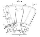
- FIG. 4schematically depicts a plan view of a compression garment, in accordance with another embodiment of the present invention.
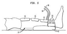
- FIG. 5schematically a side view of the compression garment of FIG. 4 attached to an individual's leg, in accordance with an embodiment of the present invention
- FIG. 6schematically depicts a plan view of a compression garment, in accordance with an embodiment of the present invention.
- FIG. 7schematically depicts a plan view of a compression garment, in accordance with an embodiment of the present invention.
- embodiments of the present inventionare configured for attachment to the leg and/or foot to provide for compression therapy while also reducing or eliminating pressure on the heel region of the foot when the leg or foot is positioned such that the heel is in contact with an underlying surface (e.g., a bed) or would be in contact with an underlying surface but for the presence of the device.
- an underlying surfacee.g., a bed
- embodiments of the present inventionmay be implemented to sufficiently elevate the foot to provide for spatial separation of the heel from an underlying surface that the heel would otherwise rest upon, such and other embodiments of the present invention need not be used to provide such spatial separation of the heel, but rather may be advantageously used to reduce pressure on the heel even if the heel is in contact with an underlying surface. Additionally, even when the foot may be cantilevered over the end of a bed or other supporting structure, embodiments of the present invention may be used to provide cantilever elevation and support, and to prevent or otherwise reduce pressure on the heel region as the individual moves while the heel is originally in a cantilevered position.
- a compression treatment systemin accordance with various embodiments of the present invention includes a controller, interconnecting tubing, and at least one inflatable garment.
- the controllermay include a pressure transducer, a manifold, and at least one output port adapted for fluidly coupling the controller to the at least one inflatable garment using interconnecting tubing.
- the at least one inflatable garmentincludes at least one inflatable bladder for providing compressive therapy to a patient's leg (e.g., thigh, calf, or ankle, or any combination thereof), and also includes at least one support member, which may include at least one inflatable bladder, for elevating the patient's heel. It is contemplated that a compression treatment system according to various embodiments of the present invention may be employed for preventing, alleviating, and/or treating conditions arising from patient immobility, such as DVT, peripheral edema, decubitus ulcers, etc.
- embodiments of compression treatment systems according to the present inventionare not limited to any particular compression chamber configuration or pumping sequence, and include and are applicable to, for example, single chamber intermittent compression garments, as well as multi-chamber sequential compression garments.
- intermittent compression garments or devicesinclude sequential compression garments or devices; said differently, a sequential compression garment or device is a particular type of intermittent compression garment or device.
- proximalrefers to a portion of a structure that is closer to a torso of a subject and the term “distal” refers to a portion that is further from the torso.
- garmentis a generic term that includes, for example, foot cuff, knee sleeve, or leg sleeve, and is neither indicative of nor limited to any particular material, material properties, or construction techniques.
- chamberand “bladder” are used interchangeably.
- FIGS. 1A and 1Bschematically depicted are plan views of a garment 10 according to an illustrative embodiment of a the present invention. More specifically, FIG. 1A is a plan view of garment 10 viewing the surface that contacts an individual's leg when garment 10 is in use (“the inner surface”), whereas FIG. 1B is a plan view of garment 10 viewing the surface opposite to the inner surface (this opposite surface also referred to herein as “the outer surface”).
- the outer contour of garment 10is configured so that garment 10 may be conformed about a patient's lower leg, extending from the ankle region and over the calf, with garment 10 being laterally wider towards the upper part of the leg (the proximal end) and tapering towards the lower part of the leg (the distal end).
- garment 10comprises three sheets of plastic (e.g., PVC) material 11 , 13 , and 20 , with sheet 13 and sheet 20 being disposed on the inner surface and outer surface, respectively, of sheet 11 .
- plastice.g., PVC
- Different materials and/or laminations of materialsmay be used for sheets 11 , 13 , and 20 , such as neoprene, rubber, polymer, resin, and/or fabric materials.
- dashed linesdenote structural features that are disposed beneath the upper sheet or layer of the surface being viewed and may be disposed on the opposite side of the backing sheet relative to the side from which the garment is being viewed.
- inner sheet 13 and outer sheet 20are more elastic than the backing sheet 11 , which in some embodiments may be substantially inelastic.
- Backing and inner sheets 11 and 13are high-frequency welded together at their peripheries and internally in a pattern 14 defining an airtight inflatable/deflatable bladder 12 and uninflatable, sealed chambers 17 and 19 .
- outer and backing sheets 20 and 11are high-frequency welded together at their peripheries and internally in a pattern 21 defining an airtight inflatable bladder 23 .
- the high frequency weldsmay be located internal to the periphery of garment 10 so that a hard edge consisting of the two material layers and weld join is avoided.
- the high frequency weldsmay be replaced by other available means for joining the materials, for example, ultrasonic welding, heat sealing, or adhesive bonding.
- bladder 23comprises three fluidly/pneumatically coupled compartments or sub-chambers 23 a , 23 b , and 23 c .
- the sub-chambersare provided to facilitate chamber 23 wrapping about the ankle region. More specifically, as will be further understood below, this configuration provides for bladder 23 to be disposed about the ankle region while bladder 12 is disposed along and about the calf region, the latter providing for intermittent calf compression while the former elevates the patient's heel.
- bladder 12is depicted as a single chamber inflatable bladder as well as a chamber having no internal pattern, it will be understood that in alternative embodiments of the invention, bladder 12 may be implemented as a single chamber bladder having internal patterning (e.g., including baffling and/or seams provided by welding or otherwise joining materials 11 and 13 in a desired pattern) or as multi-chamber inflatable bladder, with each chamber possibly having internal patterns. Additionally, in the depicted embodiment, uninflatable sealed chambers 17 and 19 are provided so that the softer more elastic material 20 contacts the skin during use. In alternative embodiments, however, such uninflatable sealed chambers need not be provided.
- bladder 23may be formed by joining (e.g., heat-welding) backing sheet 11 to sheet 20 .
- a separately formed inflatable bladdermay be attached (e.g., laminated) to backing sheet 11 .
- alternative implementations of the inventionmay include additional material layers.
- a breathable polyester foam layermay be laminated to the inner surface of garment 10 to, for example, increase comfort, reduce moisture/perspiration, and/or mitigate chafing, rash formation, and/or skin breakdown.
- one edge of garment 10has tabs 15 having hook pile fabric on the inner surface thereof to engage loop pile fabric provided at least along a portion of the outside surface of garment 10 along the opposite edge, to secure the sleeve in place on the leg.
- tabs or straps 25each includes hook pile fabric on the inner surface thereof for engaging loop pile fabric provided on the outer surface of the distal section of garment 10 comprising bladder 23 , to ensure that bladder 23 is maintained in position to provide proper and reliable heel elevation (e.g., despite patient movement).
- the hook and loop pile fabricsmay be laminated (e.g., by adhesive or welding) to appropriate portions of garment 10 .
- any of a variety of additional or alternative fastening mechanismsmay be implemented, such as zippers, buttons, straps, laces, adhesive, etc. It is understood, however, that fastening mechanisms are not necessarily required for positioning and/or conforming the heel elevation bladder, and various embodiments of the present invention may be implemented which do not include fastening mechanisms and/or which provide for removably attachable fastening mechanisms (e.g., untethered straps with hook loop material provided at each end of one surface to engage loop material provided on the outer surface of the bladder).
- the heel elevation bladdermay be configured or contoured such that it conforms about the ankle region upon inflation and securing of the garment about the patient's leg.
- Compression bladder 12 and elevation bladder 23are provided with conduits or tubes 16 and 18 , respectively, for coupling to one or more fluid sources (not shown) used for inflating these chambers.
- a fluid (e.g., gas or liquid) sourcemay be implemented as an air compressor/pump under control of a controller assembly that regulates air flow and/or pressure coupled to bladder 12 and bladder 23 via tubes 16 and 18 .
- the controller assemblymay include one or more feeder/supply valves and/or one or more exhaust valves pneumatically coupled to the bladders and to the compressor/pump, one or more pressure transducers to sense the pressure supplied to one or more bladders and/or the compressive pressure applied against the leg by the bladder(s), and a programmable processor-based control unit that monitors the pressure sensors and controls the valves to provide desired inflation/deflation timing and pressure for the compressive bladder(s) (e.g., bladder 12 in FIG. 1A ) and, in some embodiments, also to control inflation of one or more heel elevation bladders (e.g., bladder 23 in FIG. 1A ).
- the compressive bladder(s)e.g., bladder 12 in FIG. 1A
- heel elevation bladderse.g., bladder 23 in FIG. 1A
- the one or more feeder/supply valves and/or exhaust valvesmay be implemented as solenoid valves and may be configured in a valve manifold, which may further include one or more of the pressure transducers, to provide a desired pneumatic circuit configuration to provide for controlled inflation and/or deflation of garment chambers.
- bladder 12In operation, when the fluid source supplies compressed air to bladder 12 via tube 16 , bladder 12 will inflate and apply sufficient pressure to the enclosed limb to augment venous return.
- An exhaust valvee.g., in the pump manifold
- the controller unitcontrols the relative inflation pressure and timing of the sequential chambers.
- heel elevation bladder 23may be pneumatically coupled via tube 18 (and, e.g., via a valve manifold) to the same controller unit and compressor/pump used for inflating/deflating bladder 12 .
- heel elevation bladder 23 and bladder 12may be coupled via respective tubes 18 and 16 to the fluid source via parallel and independent pneumatic circuits.
- heel elevation bladder 23 and bladder 12may be alternately coupled via respective tubes 18 and 16 to the fluid source via a common pneumatic circuit path that is alternately connected to tubes 18 and 16 (e.g., using two valves synchronously switched 180 degrees out of phase). Accordingly, in this latter configuration, bladder 23 will be supplied with fluid pressure to inflate or maintain inflation during intervals that bladder 12 is deflated.
- bladder 12may include a one-way valve (e.g., attached to sheet 20 where tube 18 couples thereto, or in series with and along tube 18 ) to prevent deflation during intervals that the fluid source is connected to tube 16 .
- a one-way valvee.g., attached to sheet 20 where tube 18 couples thereto, or in series with and along tube 18
- such a one-way valveneed not be provided as the synchronously switched valve connected to tube 18 is closed during the interval that the fluid source is connected to tube 16 , thus preventing deflation during such intervals.
- the pneumatic circuit and valve switch timingmay be configured and controlled such that the fluid supply is alternately connected to each of the compressive bladders and the elevation bladder(s).
- two or more of the compression bladdersmay have independent pneumatic circuits coupled to the fluid source, and the heel elevation bladder(s) may be coupled to the fluid source via any one or more of these independent pneumatic circuits while each such pneumatic circuit is pneumatically disconnected from its associated compressive bladder (e.g., while that bladder is in a deflation state).
- independent pneumatic circuits supplying the compressive bladdersmay be multiplexed to supply one or more heel elevation bladders.
- bladder 23may be fluidly coupled via tube 18 to a separate fluid source (e.g., compressor) and controller.
- a separate fluid sourcee.g., compressor
- heel elevation bladder 23may be inflated via a one-way valve, which, for example, may be attached directly bladder 23 or pneumatically in series with tube 18 .
- heel elevation bladder 23need not be continuously or intermittently supplied by a fluid source during use.
- heel elevation bladder 23may be initially inflated using any inflation source, such as the pump/compressor used for intermittent inflation of bladder 12 , a manual pump, a compressed air cylinder coupled to a regulator, etc. After inflation, the inflation source may be disconnected from heel elevation bladder 23 , which is provided with a sealable valve or a one way valve (e.g., affixed to bladder 23 or coupled thereto, e.g., via tube 18 ) to allow for retaining the fluid (e.g., air) within bladder 23 after the inflation source is disconnected and during patient use of garment 10 .
- heel elevation bladder 23may be deflated (e.g., after use, or when the patient wishes to ambulate without removing the garment). Deflation of heel elevation bladder 23 may be provided in various ways depending on the particular implementation; for example, deflation may be provided by any combination of one or more of the following: via an exhaust valve in the pump manifold, via bladder leakage, via an exhaust valve coupled to conduit 18 , and/or via a separate releasable plug/valve (not shown) provided on the bladder 23 .
- FIG. 2schematically depicts a side view of garment 10 attached to a patient's leg, with the heel elevation bladder 23 inflated, in accordance with an embodiment of the present invention.
- the maximum displacement between the outer and inner surfaces of the bladder 23i.e., when the bladder is fully inflated
- an underlying surface 29e.g., a bed
- such maximum displacementmay be about two to four inches.
- heel elevation device 10is still useful for preventing, for example, possible abrasions or shear, possible digging of the heels in the bed, heel pressure in the event the patient moves such that the foot or leg is no longer cantilevered, as well as for reducing or preventing pressure on the Achilles tendon and/or reducing or preventing other concentrated pressure that may affect circulation.
- heel elevation bladder 23is positioned at or near the ankle region, with bladder compartment 23 b supporting the rear of the ankle and bladder compartment 23 a disposed at the side of the ankle.
- Bladder 23is inflated to a desired level of inflation (e.g., inflation pressure) to provide the desired heel elevation, cushioning/firmness, and/or stability.
- a desired level of inflatione.g., inflation pressure
- the elevation heightmay be adjustable, based on the volume (and hence pressure) of air pumped into the bladder.
- the inelasticity (and semi-rigidity in some implementations) of backing 11may also prevent or mitigate excessive inward pressure against the back of the leg as the bladder 23 is inflated, which pressure could adversely affect circulation or control of compressive pressure, particularly in view of straps 25 securing the ankle support portion about the ankle. It is understood, however, that such prevention or mitigation of inward pressure by the heel elevation bladder is not a necessary feature for implementing embodiments of the present invention. In some embodiments, at least a certain degree of inward inflation by the elevation bladder is advantageous for distributing the pressure over the back of the leg, conforming to the leg, and/or providing stable support (e.g., lateral support) for elevating the heel and reducing heel pressure.
- stable supporte.g., lateral support
- backing sheet 11may be substantially inelastic; for example, backing sheet 11 may be sufficiently or substantially inelastic such that it does not substantially deform when garment 10 is attached in position to a patient's leg for compressive therapy and bladders 12 and 23 are inflated.
- bladder 12will primarily or predominantly expand against the patient's leg as it expands upon inflation, thereby predominantly and efficiently translating and coupling the inflation pressure as compressive pressure against the patient's leg.
- bladder 23disposed on the outer surface of backing sheet 11 and backing sheet 11 being substantially inelastic, bladder 23 will primarily or predominantly expand in a posterior direction, outwardly and away from the patient's leg as it expands upon inflation, thereby avoiding unintended leg (e.g., ankle) compression that may adversely affect compressive therapy and/or adversely affect the patient (e.g., by decreasing blood flow).
- unintended lege.g., ankle
- the portion of backing sheet 11 that is disposed against the elevation bladdermay be elastic (e.g., having the same elasticity as the outer facing elevation bladder material), as inflation of the heel elevation bladder will not necessarily apply compressive pressure against the patient's leg without the heel elevation bladder portion of garment 10 being secured about the leg (e.g., ankle).
- such a configurationmay alternatively be provided by separately forming (i) the proximal portion of the garment comprising the upper compression bladder (e.g., corresponding to bladder 12 in FIG.
- the distal portion of the garmentcomprising the heel elevation bladder (e.g., similar to bladder 23 in FIG. 1A , but without an inelastic sheet) by radio-frequency welding two sheets of elastic material. Then, the proximal portion and distal portion may be welded together at their respective distal and proximal edges to form the completed garment.
- the heel elevation bladdere.g., similar to bladder 23 in FIG. 1A , but without an inelastic sheet
- heel elevation bladdermay be implemented to function for both elevating the heel and applying intermittent compressive pressure (e.g., as part of a sequential compression device).
- the heel elevation bladder portion of the garmentmay be inflated to a baseline pressure sufficient to elevate the heel at a desired level, and then secured (e.g., using straps or extensions similar to straps 25 in FIGS. 1A and 1B ) about the patient's lower leg (e.g., ankle region) such that it does not apply excessive compressive pressure against the patient's leg at the baseline pressure.
- the heel elevation bladdermay be controllably and intermittently (e.g., periodically, sequentially with one or more other bladders longitudinally disposed along the leg) inflated to a desired pressure above the baseline pressure to intermittently apply compressive pressure against the ankle region to assist venous return, with the heel elevation bladder being controllably deflated back to the baseline pressure for intervals between inflation cycles.
- FIG. 3schematically depicted is a plan view of the outer surface of a garment 40 according to an alternative embodiment of the present invention.
- garment 40is similar in construction to garment 10 depicted in FIGS. 1A and 1B .
- bladder 23is not inflated via a separate tube, but rather is pneumatically coupled to bladder 12 via lumen or tube 31 and a one-way valve 33 , which valve passes through or traverses backing sheet 11 . Accordingly, upon controlled inflation of compressive bladder 12 via tube 16 , bladder 23 will be inflated and maintained in an inflated state.
- Bladder 23may be include a pressure relief and/or exhaust valve 35 disposed through sheet 20 to ensure bladder 23 is not over-inflated and/or to deflate bladder 23 when desired. It will be understood that while in this embodiment lumen 31 is disposed on the inner surface of the garment and valve 33 traverses sheet 11 in the region of bladder 23 , in an alternative embodiment valve 33 may traverse sheet 11 within the region of bladder 12 with lumen 31 disposed on the outer surface of garment 40 .
- FIG. 4schematically depicts a plan view of the outer surface of a garment 70 , in accordance with another illustrative embodiment of the present invention.
- garment 70is similar in construction to garment 10 ; however, heel elevation bladder 43 is generally T-shaped, with a portion extending longitudinally along the outer surface of backing sheet 11 such that this longitudinal portion is disposed opposite to bladder 12 over a region that extends from approximately the mid-calf to the upper ankle when the garment is attached to a patient's leg.
- bladder 43also includes a distal portion (similar to bladder 23 ) that extends laterally and is segmented by seams 27 a and 27 b and supports the ankle region when in use.
- Tube 18is coupled into bladder 43 to provide for inflation thereof.
- tube 18may be eliminated, and bladder 43 may be pneumatically coupled to bladder 12 , similar to the pneumatic coupling of compressive pressure and heel elevation bladders in the embodiment depicted in FIG. 3 .
- FIG. 5schematically depicts a side view of garment 70 attached to a patient's leg, with the heel elevation bladder 43 inflated, in accordance with an embodiment of the present invention.
- the cross sectional profile in the sagittal planemay have a generally trapezoidal, tapered shape that generally complements the contour of the adjacent rear leg portion such that the outer surface (posterior surface) of bladder 43 is generally parallel to the shin.
- more than one separately inflatable posterior bladdermay be provided along the length (longitudinally) between the proximal and distal ends.
- the cross sectional elevation profile in the sagittal planemay thus be adjusted by separately adjusting the pressure of each posterior bladder provided.
- an elevation bladdere.g. bladder 43
- an elevation bladdermay be apportioned into multiple sections that are commonly inflated, but have different shapes or contain different volumes of fluid when the bladder is inflated.
- bladder 43may be adapted to include multiple longitudinal and/or lateral sections by, for example, separating the sections with baffles or seams that may be formed by heat sealing or welding the outer surface of the bladder (i.e., sheet 20 ) to the inner surface (i.e., sheet 11 ) along most of the extent dividing adjacent sections, but leaving an opening (lumen) between adjacent sections such that fluid (e.g., air) can flow therethrough (as will be understood, a section of tubing or foam or other fluid-permeable membrane may be positioned within the opening(s) to prevent kinking from impeding airflow). Accordingly, upon inflation, each of the sections will be filled, but the shape/profile of each section may be determined by the baffle/seam configuration/shape and the fluid containing volume of each section separated by the baffles.
- baffles or seamsmay be formed by heat sealing or welding the outer surface of the bladder (i.e., sheet 20 ) to the inner surface (i.e., sheet 11 ) along most
- FIG. 6schematically depicts a plan view of the outer surface of a garment 90 , in accordance with another illustrative embodiment of the present invention.
- garment 90is generally similar in construction to garment 10 ; however, rather than providing a heel elevation bladder that is disposed distally relative to the compression chamber(s), in this embodiment the heel elevation bladder is oppositely opposed to a compression chamber.
- garment 90includes three pneumatically separate chambers, namely, upper-calf bladder 54 fluidly coupled to tube 64 for coupling to a fluid source, lower-calf bladder 52 fluidly coupled to tube 64 for coupling to a fluid source, and lower-leg/ankle bladder 50 fluidly coupled to tube 60 for coupling to a fluid source.
- heel elevation bladder 53is disposed on the outer surface of backing sheet 11 opposite to lower-leg/ankle bladder 50 , and is fluidly coupled to tube 63 to provide for inflation thereof.
- bladder 53may include baffles/seams (not shown) to, for example, facilitate generally conforming bladder 53 about the ankle region when in use.
- tube 63may be eliminated, and bladder 53 may be pneumatically coupled to bladder 50 (e.g., using a one-way valve through intervening sheet 11 ), similar to the pneumatic coupling of compressive pressure and heel elevation bladders in the embodiment depicted in FIG. 3 .
- the pneumatically separate chambers 50 , 52 , 54may be controllably inflated and deflated to provide for sequential compression to augment venous return, as understood by those skilled in the art.
- appropriate orifices or pressure relief valvesmay be substituted for inflation tubes 62 and 64 (and associated ports/couplings into bladders 52 and 54 ), and bladders 50 , 52 , and 54 may be pneumatically coupled in series by restrictors such that these chambers are sequentially inflated upon inflation via tube 60 , in accordance with compression devices described in US Patent Publication No. US 2005/0070828 A1 to Hampson et al.
- FIG. 7schematically depicts a plan view of the outer surface of a garment 80 , in accordance with another illustrative embodiment of the present invention.
- garment 80is generally similar in construction to garment 90 ; however, garment 80 provides a thigh compression chamber, and also provides a heel elevation bladder 73 that is disposed distally relative (rather than partially or entirely opposite) to the compression chamber(s).
- garment 90includes three pneumatically independent chambers, namely, thigh-bladder 76 fluidly coupled to a tube 86 for coupling to a fluid source, upper-calf bladder 74 fluidly coupled to tube 84 for coupling to a fluid source, and lower-calf bladder 72 fluidly coupled to tube 82 for coupling to a fluid source.
- heel elevation bladder 73is disposed distally with respect to the compression chambers, and is fluidly coupled to tube 83 to provide for inflation thereof.
- Backing sheet 11includes an opening 87 to accommodate the knee when affixing the garment about a patient's leg.
- Segments 91 and 93mechanically couple the lateral ends of the elevation bladder portion to the lateral ends of the compression bladder portion of garment 80 , thus facilitating conformance of the heel elevation bladder about the ankle region (e.g., without additional straps wrapping around the ankle, such as straps 25 in the embodiment of FIGS. 1A and 1B .
- segments 91 and 93are each an integral part of sheet 11 , but in various alternative implementations may be separate/discrete members attached (e.g., by radio-frequency welding) to sheet 11 . In various alternative embodiments, segments 91 and 93 may be the only mechanical coupling between the elevation bladder portion and the compression bladder portion of garment 80 .
- compressive therapy garmentsinclude integrally attached or formed bladders that are inflatable and deflatable, it will be understood that in alternative implementations within the purview of the present invention, compressive therapy garments may alternately or additionally include integrally formed or attached (e.g., by adhesive, radio-frequency welding, etc.) heel elevation members that are not configured for inflation and/or deflation.
- heel elevation membersmay be implemented using any of a variety of preformed and/or prefilled cushioning materials such as foam cushions and/or air, gel, or other fluid filled uninflatable/undeflatable cushions, provided such heel elevation members provide sufficient elevation for mitigating and/or eliminating heel pressure.
- inflatable/deflatable bladdersare well suited for providing adjustability of elevation and cushioning/firmness, as well as for evenly distributing/redistributing pressure and conforming to the patients leg, even under dynamic load conditions (e.g., resulting from patient movements that may change the load conditions).
- more than one separately inflatable bladdermay be provided in the posterior direction to allow variable height adjustment and cushioning pressure by selectively filling one or more bladders.
- more than one separately inflatable bladdermay additionally or alternatively include a foot compression chamber together with a heel elevation bladder.
- bladdersmay be configured to have multiple pneumatically independent and/or pneumatically coupled bladder sections, and may also configured to have various contours or lobulations.
Landscapes
- Health & Medical Sciences (AREA)
- Life Sciences & Earth Sciences (AREA)
- Animal Behavior & Ethology (AREA)
- General Health & Medical Sciences (AREA)
- Public Health (AREA)
- Veterinary Medicine (AREA)
- Nursing (AREA)
- Oral & Maxillofacial Surgery (AREA)
- Engineering & Computer Science (AREA)
- Biomedical Technology (AREA)
- Massaging Devices (AREA)
Abstract
Description
Claims (16)
Priority Applications (2)
| Application Number | Priority Date | Filing Date | Title |
|---|---|---|---|
| US11/494,720US7967766B2 (en) | 2005-10-27 | 2006-07-27 | Compression garment with heel elevation |
| US12/911,563US8216165B2 (en) | 2005-10-27 | 2010-10-25 | Compression garments with heel elevation |
Applications Claiming Priority (3)
| Application Number | Priority Date | Filing Date | Title |
|---|---|---|---|
| US73076605P | 2005-10-27 | 2005-10-27 | |
| US11/356,692US7909787B2 (en) | 2005-10-27 | 2006-02-17 | Reconfigurable heel elevator |
| US11/494,720US7967766B2 (en) | 2005-10-27 | 2006-07-27 | Compression garment with heel elevation |
Related Parent Applications (1)
| Application Number | Title | Priority Date | Filing Date |
|---|---|---|---|
| US11/356,692Continuation-In-PartUS7909787B2 (en) | 2005-10-27 | 2006-02-17 | Reconfigurable heel elevator |
Related Child Applications (1)
| Application Number | Title | Priority Date | Filing Date |
|---|---|---|---|
| US11/356,692Continuation-In-PartUS7909787B2 (en) | 2005-10-27 | 2006-02-17 | Reconfigurable heel elevator |
Publications (2)
| Publication Number | Publication Date |
|---|---|
| US20070161933A1 US20070161933A1 (en) | 2007-07-12 |
| US7967766B2true US7967766B2 (en) | 2011-06-28 |
Family
ID=46325794
Family Applications (1)
| Application Number | Title | Priority Date | Filing Date |
|---|---|---|---|
| US11/494,720Expired - Fee RelatedUS7967766B2 (en) | 2005-10-27 | 2006-07-27 | Compression garment with heel elevation |
Country Status (1)
| Country | Link |
|---|---|
| US (1) | US7967766B2 (en) |
Cited By (24)
| Publication number | Priority date | Publication date | Assignee | Title |
|---|---|---|---|---|
| US20090240178A1 (en)* | 2008-03-20 | 2009-09-24 | Tyco Healthcare Group Lp | Safety connector assembly |
| US20100100017A1 (en)* | 2006-10-12 | 2010-04-22 | Pirko Maguina | Motion therapy system |
| US20110077565A1 (en)* | 2009-09-29 | 2011-03-31 | Tyco Healthcare Group Lp | Reduced noise pneumatic compression garment |
| US20110077564A1 (en)* | 2009-09-29 | 2011-03-31 | Tyco Healthcare Group Lp | Pneumatic compression garment with noise attenuating means |
| US20110087142A1 (en)* | 2005-10-27 | 2011-04-14 | Sun Scientific, Inc. | Compression garments with heel elevation |
| US20120078146A1 (en)* | 2010-09-29 | 2012-03-29 | Tyco Healthcare Group Lp | Compression garment apparatus having baseline pressure |
| US20120078145A1 (en)* | 2010-09-29 | 2012-03-29 | Tyco Healthcare Group Lp | Compression garment apparatus having support bladder |
| US8597215B2 (en) | 2007-04-09 | 2013-12-03 | Covidien Lp | Compression device with structural support features |
| US8613762B2 (en) | 2010-12-20 | 2013-12-24 | Medical Technology Inc. | Cold therapy apparatus using heat exchanger |
| US8622942B2 (en) | 2007-04-09 | 2014-01-07 | Covidien Lp | Method of making compression sleeve with structural support features |
| US8632840B2 (en) | 2008-09-30 | 2014-01-21 | Covidien Lp | Compression device with wear area |
| US8721575B2 (en) | 2007-04-09 | 2014-05-13 | Covidien Lp | Compression device with s-shaped bladder |
| US8740828B2 (en) | 2007-04-09 | 2014-06-03 | Covidien Lp | Compression device with improved moisture evaporation |
| US8801644B2 (en) | 2009-09-29 | 2014-08-12 | Covidien Lp | Pneumatic compression garment with noise attenuation |
| US20150047303A1 (en)* | 2013-08-13 | 2015-02-19 | Sharon Ann Caswell | Long-Wear Equine Diagnostic Boot |
| US9033906B2 (en) | 2010-08-12 | 2015-05-19 | Sun Scientific, Inc. | Therapeutic compression apparatus |
| US9084713B2 (en) | 2007-04-09 | 2015-07-21 | Covidien Lp | Compression device having cooling capability |
| US9114055B2 (en) | 2012-03-13 | 2015-08-25 | Cothera Llc | Deep vein thrombosis (“DVT”) and thermal/compression therapy systems, apparatuses and methods |
| US9114052B2 (en) | 2007-04-09 | 2015-08-25 | Covidien Lp | Compression device with strategic weld construction |
| US9205021B2 (en) | 2012-06-18 | 2015-12-08 | Covidien Lp | Compression system with vent cooling feature |
| US9364037B2 (en) | 2005-07-26 | 2016-06-14 | Covidien Ag | Limited durability fastening for a garment |
| US9387146B2 (en) | 2007-04-09 | 2016-07-12 | Covidien Lp | Compression device having weld seam moisture transfer |
| US9402763B2 (en) | 2012-09-12 | 2016-08-02 | Breg, Inc. | Cold therapy apparatus having heat exchanging therapy pad |
| US9566187B2 (en) | 2012-03-13 | 2017-02-14 | Breg, Inc. | Cold therapy systems and methods |
Families Citing this family (41)
| Publication number | Priority date | Publication date | Assignee | Title |
|---|---|---|---|---|
| US7871387B2 (en) | 2004-02-23 | 2011-01-18 | Tyco Healthcare Group Lp | Compression sleeve convertible in length |
| US8029451B2 (en) | 2005-12-12 | 2011-10-04 | Tyco Healthcare Group Lp | Compression sleeve having air conduits |
| US7931606B2 (en) | 2005-12-12 | 2011-04-26 | Tyco Healthcare Group Lp | Compression apparatus |
| US7837638B2 (en) | 2007-02-13 | 2010-11-23 | Coolsystems, Inc. | Flexible joint wrap |
| US8021388B2 (en) | 2007-04-09 | 2011-09-20 | Tyco Healthcare Group Lp | Compression device with improved moisture evaporation |
| US8029450B2 (en) | 2007-04-09 | 2011-10-04 | Tyco Healthcare Group Lp | Breathable compression device |
| USD608006S1 (en) | 2007-04-09 | 2010-01-12 | Tyco Healthcare Group Lp | Compression device |
| US8016778B2 (en) | 2007-04-09 | 2011-09-13 | Tyco Healthcare Group Lp | Compression device with improved moisture evaporation |
| US20090292212A1 (en)* | 2008-05-20 | 2009-11-26 | Searete Llc, A Limited Corporation Of The State Of Delaware | Circulatory monitoring systems and methods |
| US9672471B2 (en) | 2007-12-18 | 2017-06-06 | Gearbox Llc | Systems, devices, and methods for detecting occlusions in a biological subject including spectral learning |
| US9717896B2 (en) | 2007-12-18 | 2017-08-01 | Gearbox, Llc | Treatment indications informed by a priori implant information |
| US8636678B2 (en) | 2008-07-01 | 2014-01-28 | Covidien Lp | Inflatable member for compression foot cuff |
| US8235923B2 (en) | 2008-09-30 | 2012-08-07 | Tyco Healthcare Group Lp | Compression device with removable portion |
| WO2010065644A2 (en)* | 2008-12-02 | 2010-06-10 | Eddy Patrick E | Compression device and control system for applying pressure to a limb of a living being |
| US8161916B2 (en) | 2009-01-07 | 2012-04-24 | University Of Louisville Research Foundation, Inc. | Decubitus ulcer prevention garment for dogs |
| EP3714848A1 (en)* | 2009-10-22 | 2020-09-30 | Coolsystems, Inc. | Temperature and flow control methods in a thermal therapy device |
| US8652079B2 (en) | 2010-04-02 | 2014-02-18 | Covidien Lp | Compression garment having an extension |
| US10751221B2 (en) | 2010-09-14 | 2020-08-25 | Kpr U.S., Llc | Compression sleeve with improved position retention |
| US8096964B1 (en) | 2010-09-29 | 2012-01-17 | Tyco Healthcare Group Lp | Compression garment having grip |
| US8597217B2 (en)* | 2010-12-30 | 2013-12-03 | Coolsystems, Inc. | Reinforced therapeutic wrap and method |
| US9615967B2 (en)* | 2010-12-30 | 2017-04-11 | Coolsystems, Inc. | Reinforced therapeutic wrap and method |
| US9119760B2 (en)* | 2011-06-09 | 2015-09-01 | William Purdy | Compression device in combination with lower limb protection |
| US10016326B2 (en)* | 2011-06-09 | 2018-07-10 | Molnycke Health Care Ab | Compression device in combination with lower limb protection |
| US10463565B2 (en) | 2011-06-17 | 2019-11-05 | Coolsystems, Inc. | Adjustable patient therapy device |
| TWM424934U (en)* | 2011-11-29 | 2012-03-21 | Zhan Rui Peng | Capsular bag type rehabilitation device |
| US9655627B2 (en)* | 2012-05-11 | 2017-05-23 | Michael Zhadkevich | Anti-embolic device and method |
| US10130374B2 (en) | 2012-05-11 | 2018-11-20 | Michael Zhadkevich | Anti-embolic device and method |
| GB201219496D0 (en)* | 2012-10-30 | 2012-12-12 | Huntleigh Technology Ltd | Pressure cuff or garment |
| USD717453S1 (en)* | 2013-06-12 | 2014-11-11 | Novitas Medical, Llc | Calf pad |
| US10456320B2 (en) | 2013-10-01 | 2019-10-29 | Coolsystems, Inc. | Hand and foot wraps |
| USD774652S1 (en)* | 2014-04-10 | 2016-12-20 | Covidien Lp | Compression garment with openings |
| US20160038336A1 (en) | 2014-08-05 | 2016-02-11 | Tamara L. HILTON | Integrated multisectional heat exchanger |
| EP3050520A1 (en) | 2015-01-27 | 2016-08-03 | Michael Zhadkevich | Devices and techniques for vascular compression |
| US10179062B2 (en)* | 2015-03-30 | 2019-01-15 | J. Michael Putman | Medical devices and methods for protecting a limb of a patient during a medical procedure |
| US10583046B2 (en) | 2015-08-12 | 2020-03-10 | Eric Wilson | Compression garments and uses thereof |
| US11103416B2 (en) | 2015-09-28 | 2021-08-31 | Michael Zhadkevich | Device and method for simultaneous detection, monitoring and prevention of cerebral emboli |
| US10859295B2 (en) | 2016-04-13 | 2020-12-08 | ZeoThermal Technologies, LLC | Cooling and heating platform |
| WO2019059848A2 (en)* | 2017-09-22 | 2019-03-28 | Mas Innovation (Private) Limited | Compression devices |
| US10893998B2 (en)* | 2018-10-10 | 2021-01-19 | Inova Labs Inc. | Compression apparatus and systems for circulatory disorders |
| US11364053B2 (en)* | 2019-06-14 | 2022-06-21 | Terumo Medical Corporation | Tibiopedal vascular closure band |
| WO2025029539A2 (en)* | 2023-07-31 | 2025-02-06 | Sage Products, Llc | Wedge cushioning systems |
Citations (48)
| Publication number | Priority date | Publication date | Assignee | Title |
|---|---|---|---|---|
| US3939829A (en) | 1974-07-09 | 1976-02-24 | Spann Donald C | Restraining cuff |
| US3946451A (en) | 1974-08-19 | 1976-03-30 | Spann Donald C | Limb support |
| US4013069A (en) | 1975-10-28 | 1977-03-22 | The Kendall Company | Sequential intermittent compression device |
| US4030488A (en) | 1975-10-28 | 1977-06-21 | The Kendall Company | Intermittent compression device |
| US4054129A (en)* | 1976-03-29 | 1977-10-18 | Alba-Waldensian, Inc. | System for applying pulsating pressure to the body |
| US4186738A (en) | 1978-02-15 | 1980-02-05 | Drennan Denis B | Heel supporting boot for bed patients |
| US4197845A (en) | 1978-06-05 | 1980-04-15 | Browning Edward G | Device for the prevention of decubitus ulcers on the human heel |
| US4266298A (en)* | 1980-01-31 | 1981-05-12 | Marlene S. Mindey | Inflatable heel protector |
| US4320746A (en) | 1979-12-07 | 1982-03-23 | The Kendall Company | Compression device with improved pressure control |
| US4399815A (en) | 1981-05-13 | 1983-08-23 | Bachorik Joan E | Pneumatic therapeutic heel and ankle guard |
| US4402312A (en) | 1981-08-21 | 1983-09-06 | The Kendall Company | Compression device |
| US4409975A (en) | 1981-05-29 | 1983-10-18 | Orit Simhoni | Negative heel protector cushion |
| US4730610A (en) | 1985-05-06 | 1988-03-15 | Graebe Robert H | Foot and elbow cushion device |
| US4944060A (en) | 1989-03-03 | 1990-07-31 | Peery John R | Mattress assembly for the prevention and treatment of decubitus ulcers |
| US5085214A (en) | 1990-10-18 | 1992-02-04 | Twenty-First Century Products, Incorporated | Inflatable cushion for supporting an extremity |
| US5226245A (en) | 1991-09-20 | 1993-07-13 | Lamont William D | Protective boot structure |
| US5328445A (en) | 1993-01-15 | 1994-07-12 | Ehob, Inc. | Inflatable foot cushion |
| US5412822A (en) | 1993-10-15 | 1995-05-09 | Kelly; Bryan J. | Adjustable multi-compartment pneumatic support apparatus |
| US5431624A (en) | 1994-03-23 | 1995-07-11 | Saxton; Loren | Therapeutic device for controlling orientation of a patient's foot with respect to the patients leg during a recovery period |
| US5435009A (en) | 1992-10-01 | 1995-07-25 | Huntleigh Technology Plc | Inflatable compression garment |
| US5449339A (en) | 1994-05-06 | 1995-09-12 | Dm Systems, Inc. | Heel supporting protective boot for bed patients |
| US5476105A (en) | 1992-07-13 | 1995-12-19 | Toth; Julie O. | Abduction pillow for orthopedic support |
| US5489259A (en) | 1993-10-27 | 1996-02-06 | Sundance Enterprises, Inc. | Pressure-normalizing single-chambered static pressure device for supporting and protecting a body extremity |
| US5666681A (en) | 1995-01-03 | 1997-09-16 | Hill-Rom, Inc. | Heel pressure management apparatus and method |
| US5711760A (en) | 1993-03-15 | 1998-01-27 | Englewood Research Associates | Self-inflating venous boot |
| US5765564A (en) | 1997-05-27 | 1998-06-16 | Ewing; Brad H. | Medical limb support assembly |
| US5839139A (en) | 1997-04-24 | 1998-11-24 | John Fink | Heel elevator for the prevention of heel and foot ulcerations |
| US5876364A (en) | 1998-07-13 | 1999-03-02 | Herbst; R. Jamey | Orthotic cushioned article to prevent foot and ankle decubital ulcers |
| US5913841A (en) | 1994-11-21 | 1999-06-22 | Lamont; William D. | Medical boot with detachable sole for wound care application |
| US5957872A (en) | 1997-09-04 | 1999-09-28 | Gaymar Industries, Inc. | Heel care device and method |
| US5957874A (en) | 1998-01-16 | 1999-09-28 | Tharos Llc | Heel elevating device |
| US5997491A (en) | 1997-11-07 | 1999-12-07 | Harris; Arthur L. | Heel support apparatus |
| US6001119A (en) | 1997-08-09 | 1999-12-14 | Huntleigh Technology, Plc | Compression system |
| US6175979B1 (en) | 1999-03-05 | 2001-01-23 | John C. Jackson | Inflatable orthopedic pillow |
| US6260221B1 (en) | 1999-08-13 | 2001-07-17 | Marc Grabell | Medical apparatus for the treatment and prevention of heel decubitus |
| US6290662B1 (en) | 1999-05-28 | 2001-09-18 | John K. Morris | Portable, self-contained apparatus for deep vein thrombosis (DVT) prophylaxis |
| US20020032485A1 (en) | 2000-03-29 | 2002-03-14 | Eric Flam | Apparatus and methods for preventing and/or healing pressure ulcers |
| US6494852B1 (en) | 1998-03-11 | 2002-12-17 | Medical Compression Systems (Dbn) Ltd. | Portable ambulant pneumatic compression system |
| US20030028135A1 (en)* | 2001-07-13 | 2003-02-06 | Flick Roland E. | Support device with pressure adjustment section and method of use |
| US6572573B1 (en)* | 1998-01-16 | 2003-06-03 | Tharos Llc | Heel elevating device |
| US20030182727A1 (en) | 2002-04-01 | 2003-10-02 | Dudonis Matt | Heel elevator support |
| US6786879B1 (en) | 1994-04-05 | 2004-09-07 | Kci Licensing, Inc. | Gradient sequential compression system for preventing deep vein thrombosis |
| US6789284B2 (en) | 2000-12-09 | 2004-09-14 | Huntleigh Technology, Plc | Inflatable support |
| US20050060808A1 (en) | 2003-09-22 | 2005-03-24 | Mark Shaw | Antidecubitus heel pad |
| US20050070828A1 (en) | 2001-07-20 | 2005-03-31 | Huntleigh Technology Plc | Inflatable apparatus |
| US6877178B2 (en) | 2001-03-15 | 2005-04-12 | Huntleigh Technology, Plc | Inflatable support |
| US20050107728A1 (en) | 2003-11-17 | 2005-05-19 | Vetters Kurt M. | Therapeutic socks |
| US20050222526A1 (en) | 2004-02-23 | 2005-10-06 | Tyco Healthcare Group Lp | Garment detection method and system for delivering compression treatment |
Family Cites Families (1)
| Publication number | Priority date | Publication date | Assignee | Title |
|---|---|---|---|---|
| US4736610A (en)* | 1984-08-03 | 1988-04-12 | North American Agricultural, Inc. | Method and apparatus for making grain bin flooring |
- 2006
- 2006-07-27USUS11/494,720patent/US7967766B2/ennot_activeExpired - Fee Related
Patent Citations (54)
| Publication number | Priority date | Publication date | Assignee | Title |
|---|---|---|---|---|
| US3939829A (en) | 1974-07-09 | 1976-02-24 | Spann Donald C | Restraining cuff |
| US3946451A (en) | 1974-08-19 | 1976-03-30 | Spann Donald C | Limb support |
| US4013069A (en) | 1975-10-28 | 1977-03-22 | The Kendall Company | Sequential intermittent compression device |
| US4030488A (en) | 1975-10-28 | 1977-06-21 | The Kendall Company | Intermittent compression device |
| US4054129A (en)* | 1976-03-29 | 1977-10-18 | Alba-Waldensian, Inc. | System for applying pulsating pressure to the body |
| US4186738A (en) | 1978-02-15 | 1980-02-05 | Drennan Denis B | Heel supporting boot for bed patients |
| US4197845A (en) | 1978-06-05 | 1980-04-15 | Browning Edward G | Device for the prevention of decubitus ulcers on the human heel |
| US4320746A (en) | 1979-12-07 | 1982-03-23 | The Kendall Company | Compression device with improved pressure control |
| US4266298A (en)* | 1980-01-31 | 1981-05-12 | Marlene S. Mindey | Inflatable heel protector |
| US4266298B1 (en)* | 1980-01-31 | 1996-05-21 | Mindey Marlene S | Inflatable heel protector |
| US4399815A (en) | 1981-05-13 | 1983-08-23 | Bachorik Joan E | Pneumatic therapeutic heel and ankle guard |
| US4409975A (en) | 1981-05-29 | 1983-10-18 | Orit Simhoni | Negative heel protector cushion |
| US4402312A (en) | 1981-08-21 | 1983-09-06 | The Kendall Company | Compression device |
| US4730610A (en) | 1985-05-06 | 1988-03-15 | Graebe Robert H | Foot and elbow cushion device |
| US4944060A (en) | 1989-03-03 | 1990-07-31 | Peery John R | Mattress assembly for the prevention and treatment of decubitus ulcers |
| US5085214A (en) | 1990-10-18 | 1992-02-04 | Twenty-First Century Products, Incorporated | Inflatable cushion for supporting an extremity |
| US5226245A (en) | 1991-09-20 | 1993-07-13 | Lamont William D | Protective boot structure |
| US5476105A (en) | 1992-07-13 | 1995-12-19 | Toth; Julie O. | Abduction pillow for orthopedic support |
| US5435009A (en) | 1992-10-01 | 1995-07-25 | Huntleigh Technology Plc | Inflatable compression garment |
| US5328445A (en) | 1993-01-15 | 1994-07-12 | Ehob, Inc. | Inflatable foot cushion |
| US5711760A (en) | 1993-03-15 | 1998-01-27 | Englewood Research Associates | Self-inflating venous boot |
| US5412822A (en) | 1993-10-15 | 1995-05-09 | Kelly; Bryan J. | Adjustable multi-compartment pneumatic support apparatus |
| US5489259A (en) | 1993-10-27 | 1996-02-06 | Sundance Enterprises, Inc. | Pressure-normalizing single-chambered static pressure device for supporting and protecting a body extremity |
| US5431624A (en) | 1994-03-23 | 1995-07-11 | Saxton; Loren | Therapeutic device for controlling orientation of a patient's foot with respect to the patients leg during a recovery period |
| US6786879B1 (en) | 1994-04-05 | 2004-09-07 | Kci Licensing, Inc. | Gradient sequential compression system for preventing deep vein thrombosis |
| US5449339A (en) | 1994-05-06 | 1995-09-12 | Dm Systems, Inc. | Heel supporting protective boot for bed patients |
| US5913841A (en) | 1994-11-21 | 1999-06-22 | Lamont; William D. | Medical boot with detachable sole for wound care application |
| US5666681A (en) | 1995-01-03 | 1997-09-16 | Hill-Rom, Inc. | Heel pressure management apparatus and method |
| US6151739A (en) | 1995-01-03 | 2000-11-28 | Hill-Rom, Inc. | Heel pressure management apparatus and method |
| US6351863B1 (en) | 1995-01-03 | 2002-03-05 | Hill-Rom Services, Inc. | Heel pressure management apparatus and method |
| US5839139A (en) | 1997-04-24 | 1998-11-24 | John Fink | Heel elevator for the prevention of heel and foot ulcerations |
| US5765564A (en) | 1997-05-27 | 1998-06-16 | Ewing; Brad H. | Medical limb support assembly |
| US6001119A (en) | 1997-08-09 | 1999-12-14 | Huntleigh Technology, Plc | Compression system |
| US5957872A (en) | 1997-09-04 | 1999-09-28 | Gaymar Industries, Inc. | Heel care device and method |
| US5997491A (en) | 1997-11-07 | 1999-12-07 | Harris; Arthur L. | Heel support apparatus |
| US6572573B1 (en)* | 1998-01-16 | 2003-06-03 | Tharos Llc | Heel elevating device |
| US6149613A (en) | 1998-01-16 | 2000-11-21 | Tharos Llc | Heel elevating device |
| US5957874A (en) | 1998-01-16 | 1999-09-28 | Tharos Llc | Heel elevating device |
| US6494852B1 (en) | 1998-03-11 | 2002-12-17 | Medical Compression Systems (Dbn) Ltd. | Portable ambulant pneumatic compression system |
| US5876364A (en) | 1998-07-13 | 1999-03-02 | Herbst; R. Jamey | Orthotic cushioned article to prevent foot and ankle decubital ulcers |
| US6175979B1 (en) | 1999-03-05 | 2001-01-23 | John C. Jackson | Inflatable orthopedic pillow |
| US6290662B1 (en) | 1999-05-28 | 2001-09-18 | John K. Morris | Portable, self-contained apparatus for deep vein thrombosis (DVT) prophylaxis |
| US20010016960A1 (en) | 1999-08-13 | 2001-08-30 | Marc Grabell | Medical apparatus for the treatment and prevention of heel decubitus |
| US6260221B1 (en) | 1999-08-13 | 2001-07-17 | Marc Grabell | Medical apparatus for the treatment and prevention of heel decubitus |
| US20020032485A1 (en) | 2000-03-29 | 2002-03-14 | Eric Flam | Apparatus and methods for preventing and/or healing pressure ulcers |
| US6789284B2 (en) | 2000-12-09 | 2004-09-14 | Huntleigh Technology, Plc | Inflatable support |
| US6877178B2 (en) | 2001-03-15 | 2005-04-12 | Huntleigh Technology, Plc | Inflatable support |
| US20030028135A1 (en)* | 2001-07-13 | 2003-02-06 | Flick Roland E. | Support device with pressure adjustment section and method of use |
| US20050070828A1 (en) | 2001-07-20 | 2005-03-31 | Huntleigh Technology Plc | Inflatable apparatus |
| US20030182727A1 (en) | 2002-04-01 | 2003-10-02 | Dudonis Matt | Heel elevator support |
| US6634045B1 (en) | 2002-04-01 | 2003-10-21 | Dudonis Matt | Heel elevator support |
| US20050060808A1 (en) | 2003-09-22 | 2005-03-24 | Mark Shaw | Antidecubitus heel pad |
| US20050107728A1 (en) | 2003-11-17 | 2005-05-19 | Vetters Kurt M. | Therapeutic socks |
| US20050222526A1 (en) | 2004-02-23 | 2005-10-06 | Tyco Healthcare Group Lp | Garment detection method and system for delivering compression treatment |
Cited By (38)
| Publication number | Priority date | Publication date | Assignee | Title |
|---|---|---|---|---|
| US9364037B2 (en) | 2005-07-26 | 2016-06-14 | Covidien Ag | Limited durability fastening for a garment |
| US20110087142A1 (en)* | 2005-10-27 | 2011-04-14 | Sun Scientific, Inc. | Compression garments with heel elevation |
| US8216165B2 (en) | 2005-10-27 | 2012-07-10 | Sundaram Ravikumar | Compression garments with heel elevation |
| US20100100017A1 (en)* | 2006-10-12 | 2010-04-22 | Pirko Maguina | Motion therapy system |
| US8622942B2 (en) | 2007-04-09 | 2014-01-07 | Covidien Lp | Method of making compression sleeve with structural support features |
| US8721575B2 (en) | 2007-04-09 | 2014-05-13 | Covidien Lp | Compression device with s-shaped bladder |
| US9808395B2 (en) | 2007-04-09 | 2017-11-07 | Covidien Lp | Compression device having cooling capability |
| US8992449B2 (en) | 2007-04-09 | 2015-03-31 | Covidien Lp | Method of making compression sleeve with structural support features |
| US9084713B2 (en) | 2007-04-09 | 2015-07-21 | Covidien Lp | Compression device having cooling capability |
| US9114052B2 (en) | 2007-04-09 | 2015-08-25 | Covidien Lp | Compression device with strategic weld construction |
| US8597215B2 (en) | 2007-04-09 | 2013-12-03 | Covidien Lp | Compression device with structural support features |
| US9107793B2 (en) | 2007-04-09 | 2015-08-18 | Covidien Lp | Compression device with structural support features |
| US8740828B2 (en) | 2007-04-09 | 2014-06-03 | Covidien Lp | Compression device with improved moisture evaporation |
| US9387146B2 (en) | 2007-04-09 | 2016-07-12 | Covidien Lp | Compression device having weld seam moisture transfer |
| US20090240178A1 (en)* | 2008-03-20 | 2009-09-24 | Tyco Healthcare Group Lp | Safety connector assembly |
| US8257287B2 (en)* | 2008-03-20 | 2012-09-04 | Tyco Healthcare Group Lp | Safety connector assembly |
| US10137052B2 (en) | 2008-04-07 | 2018-11-27 | Kpr U.S., Llc | Compression device with wear area |
| US8632840B2 (en) | 2008-09-30 | 2014-01-21 | Covidien Lp | Compression device with wear area |
| US8801644B2 (en) | 2009-09-29 | 2014-08-12 | Covidien Lp | Pneumatic compression garment with noise attenuation |
| US20110077564A1 (en)* | 2009-09-29 | 2011-03-31 | Tyco Healthcare Group Lp | Pneumatic compression garment with noise attenuating means |
| US9572720B2 (en) | 2009-09-29 | 2017-02-21 | Covidien Lp | Reduced noise pneumatic compression garment |
| US20110077565A1 (en)* | 2009-09-29 | 2011-03-31 | Tyco Healthcare Group Lp | Reduced noise pneumatic compression garment |
| US9033905B2 (en) | 2009-09-29 | 2015-05-19 | Covidien Lp | Pneumatic compression garment with noise attenuating means |
| US8469910B2 (en) | 2009-09-29 | 2013-06-25 | Covidien Lp | Pneumatic compression garment with noise attenuating means |
| US9033906B2 (en) | 2010-08-12 | 2015-05-19 | Sun Scientific, Inc. | Therapeutic compression apparatus |
| US8753300B2 (en)* | 2010-09-29 | 2014-06-17 | Covidien Lp | Compression garment apparatus having baseline pressure |
| US8758282B2 (en)* | 2010-09-29 | 2014-06-24 | Covidien Lp | Compression garment apparatus having support bladder |
| US20120078145A1 (en)* | 2010-09-29 | 2012-03-29 | Tyco Healthcare Group Lp | Compression garment apparatus having support bladder |
| US20120078146A1 (en)* | 2010-09-29 | 2012-03-29 | Tyco Healthcare Group Lp | Compression garment apparatus having baseline pressure |
| US9717642B2 (en) | 2010-09-29 | 2017-08-01 | Covidien Lp | Compression garment apparatus having baseline pressure |
| US9421142B2 (en) | 2010-09-29 | 2016-08-23 | Covidien Lp | Compression garment apparatus having support bladder |
| US8613762B2 (en) | 2010-12-20 | 2013-12-24 | Medical Technology Inc. | Cold therapy apparatus using heat exchanger |
| US9114055B2 (en) | 2012-03-13 | 2015-08-25 | Cothera Llc | Deep vein thrombosis (“DVT”) and thermal/compression therapy systems, apparatuses and methods |
| US9566187B2 (en) | 2012-03-13 | 2017-02-14 | Breg, Inc. | Cold therapy systems and methods |
| US9205021B2 (en) | 2012-06-18 | 2015-12-08 | Covidien Lp | Compression system with vent cooling feature |
| US9402763B2 (en) | 2012-09-12 | 2016-08-02 | Breg, Inc. | Cold therapy apparatus having heat exchanging therapy pad |
| US9351477B2 (en)* | 2013-08-13 | 2016-05-31 | Sharon Ann Caswell | Long-wear equine diagnostic boot |
| US20150047303A1 (en)* | 2013-08-13 | 2015-02-19 | Sharon Ann Caswell | Long-Wear Equine Diagnostic Boot |
Also Published As
| Publication number | Publication date |
|---|---|
| US20070161933A1 (en) | 2007-07-12 |
Similar Documents
| Publication | Publication Date | Title |
|---|---|---|
| US7967766B2 (en) | Compression garment with heel elevation | |
| US8216165B2 (en) | Compression garments with heel elevation | |
| CN109789050B (en) | Therapeutic compression devices and methods of use | |
| CA2552331C (en) | Compression apparatus | |
| US7871387B2 (en) | Compression sleeve convertible in length | |
| US6852089B2 (en) | Compression garment for selective application for treatment of lymphedema and related illnesses manifested at various locations of the body | |
| US7931606B2 (en) | Compression apparatus | |
| EP1893143B1 (en) | A cuff for providing compression to a limb | |
| AU2005297079B2 (en) | Compression device for the limb | |
| US20050154336A1 (en) | Segmented pneumatic pad for regulating pressure upon parts of the body during usage | |
| US20120316480A1 (en) | Therapeutic compression apparatus | |
| CA2795368A1 (en) | Compression sleeve having air conduit | |
| WO2012142155A2 (en) | Therapeutic compression apparatus | |
| WO2023211761A2 (en) | Saphenous vein compression systems and methods of use | |
| US20140276286A1 (en) | Non-Woven Garment For Deep Vein Thrombosis Prevention | |
| HK1091390B (en) | Compression apparatus |
Legal Events
| Date | Code | Title | Description |
|---|---|---|---|
| STCF | Information on status: patent grant | Free format text:PATENTED CASE | |
| FEPP | Fee payment procedure | Free format text:PAYER NUMBER DE-ASSIGNED (ORIGINAL EVENT CODE: RMPN); ENTITY STATUS OF PATENT OWNER: SMALL ENTITY Free format text:PAYOR NUMBER ASSIGNED (ORIGINAL EVENT CODE: ASPN); ENTITY STATUS OF PATENT OWNER: SMALL ENTITY | |
| REMI | Maintenance fee reminder mailed | ||
| AS | Assignment | Owner name:SUN SCIENTIFIC, INC., NEW YORK Free format text:ASSIGNMENT OF ASSIGNORS INTEREST;ASSIGNOR:RAVIKUMAR, SUNDARAM, DR.;REEL/FRAME:035174/0590 Effective date:20150316 | |
| FPAY | Fee payment | Year of fee payment:4 | |
| SULP | Surcharge for late payment | ||
| FEPP | Fee payment procedure | Free format text:MAINTENANCE FEE REMINDER MAILED (ORIGINAL EVENT CODE: REM.); ENTITY STATUS OF PATENT OWNER: SMALL ENTITY | |
| LAPS | Lapse for failure to pay maintenance fees | Free format text:PATENT EXPIRED FOR FAILURE TO PAY MAINTENANCE FEES (ORIGINAL EVENT CODE: EXP.); ENTITY STATUS OF PATENT OWNER: SMALL ENTITY | |
| STCH | Information on status: patent discontinuation | Free format text:PATENT EXPIRED DUE TO NONPAYMENT OF MAINTENANCE FEES UNDER 37 CFR 1.362 | |
| FP | Lapsed due to failure to pay maintenance fee | Effective date:20190628 | |
| PRDP | Patent reinstated due to the acceptance of a late maintenance fee | Effective date:20190910 | |
| FEPP | Fee payment procedure | Free format text:SURCHARGE, PETITION TO ACCEPT PYMT AFTER EXP, UNINTENTIONAL. (ORIGINAL EVENT CODE: M2558); ENTITY STATUS OF PATENT OWNER: SMALL ENTITY Free format text:PETITION RELATED TO MAINTENANCE FEES FILED (ORIGINAL EVENT CODE: PMFP); ENTITY STATUS OF PATENT OWNER: SMALL ENTITY Free format text:PETITION RELATED TO MAINTENANCE FEES GRANTED (ORIGINAL EVENT CODE: PMFG); ENTITY STATUS OF PATENT OWNER: SMALL ENTITY | |
| MAFP | Maintenance fee payment | Free format text:PAYMENT OF MAINTENANCE FEE, 8TH YR, SMALL ENTITY (ORIGINAL EVENT CODE: M2552); ENTITY STATUS OF PATENT OWNER: SMALL ENTITY Year of fee payment:8 | |
| STCF | Information on status: patent grant | Free format text:PATENTED CASE | |
| FEPP | Fee payment procedure | Free format text:MAINTENANCE FEE REMINDER MAILED (ORIGINAL EVENT CODE: REM.); ENTITY STATUS OF PATENT OWNER: SMALL ENTITY | |
| LAPS | Lapse for failure to pay maintenance fees | Free format text:PATENT EXPIRED FOR FAILURE TO PAY MAINTENANCE FEES (ORIGINAL EVENT CODE: EXP.); ENTITY STATUS OF PATENT OWNER: SMALL ENTITY | |
| STCH | Information on status: patent discontinuation | Free format text:PATENT EXPIRED DUE TO NONPAYMENT OF MAINTENANCE FEES UNDER 37 CFR 1.362 | |
| FP | Lapsed due to failure to pay maintenance fee | Effective date:20230628 |