US7967761B2 - Sensor and guide wire assembly - Google Patents
Sensor and guide wire assemblyDownload PDFInfo
- Publication number
- US7967761B2 US7967761B2US11/607,120US60712006AUS7967761B2US 7967761 B2US7967761 B2US 7967761B2US 60712006 AUS60712006 AUS 60712006AUS 7967761 B2US7967761 B2US 7967761B2
- Authority
- US
- United States
- Prior art keywords
- sensor
- guide wire
- distal
- external contour
- wire assembly
- Prior art date
- Legal status (The legal status is an assumption and is not a legal conclusion. Google has not performed a legal analysis and makes no representation as to the accuracy of the status listed.)
- Expired - Fee Related, expires
Links
Images


Classifications
- A—HUMAN NECESSITIES
- A61—MEDICAL OR VETERINARY SCIENCE; HYGIENE
- A61B—DIAGNOSIS; SURGERY; IDENTIFICATION
- A61B5/00—Measuring for diagnostic purposes; Identification of persons
- A61B5/03—Measuring fluid pressure within the body other than blood pressure, e.g. cerebral pressure ; Measuring pressure in body tissues or organs
- A61B5/036—Measuring fluid pressure within the body other than blood pressure, e.g. cerebral pressure ; Measuring pressure in body tissues or organs by means introduced into body tracts
- A—HUMAN NECESSITIES
- A61—MEDICAL OR VETERINARY SCIENCE; HYGIENE
- A61B—DIAGNOSIS; SURGERY; IDENTIFICATION
- A61B5/00—Measuring for diagnostic purposes; Identification of persons
- A61B5/68—Arrangements of detecting, measuring or recording means, e.g. sensors, in relation to patient
- A61B5/6846—Arrangements of detecting, measuring or recording means, e.g. sensors, in relation to patient specially adapted to be brought in contact with an internal body part, i.e. invasive
- A61B5/6847—Arrangements of detecting, measuring or recording means, e.g. sensors, in relation to patient specially adapted to be brought in contact with an internal body part, i.e. invasive mounted on an invasive device
- A61B5/6851—Guide wires
- A—HUMAN NECESSITIES
- A61—MEDICAL OR VETERINARY SCIENCE; HYGIENE
- A61M—DEVICES FOR INTRODUCING MEDIA INTO, OR ONTO, THE BODY; DEVICES FOR TRANSDUCING BODY MEDIA OR FOR TAKING MEDIA FROM THE BODY; DEVICES FOR PRODUCING OR ENDING SLEEP OR STUPOR
- A61M25/00—Catheters; Hollow probes
- A61M25/01—Introducing, guiding, advancing, emplacing or holding catheters
- A61M25/09—Guide wires
- A61M25/09016—Guide wires with mandrils
- A61M25/09033—Guide wires with mandrils with fixed mandrils, e.g. mandrils fixed to tip; Tensionable wires
- A—HUMAN NECESSITIES
- A61—MEDICAL OR VETERINARY SCIENCE; HYGIENE
- A61M—DEVICES FOR INTRODUCING MEDIA INTO, OR ONTO, THE BODY; DEVICES FOR TRANSDUCING BODY MEDIA OR FOR TAKING MEDIA FROM THE BODY; DEVICES FOR PRODUCING OR ENDING SLEEP OR STUPOR
- A61M25/00—Catheters; Hollow probes
- A61M2025/0001—Catheters; Hollow probes for pressure measurement
- A61M2025/0002—Catheters; Hollow probes for pressure measurement with a pressure sensor at the distal end
Definitions
- the inventionrelates generally to a sensor mounted in a distal portion of a guide wire for intravascular measurements of physiological variables in a living body, and in particular to the design of said distal portion.
- Sensor and guide wire assembliesin which a sensor, adapted for measurements of physiological variables in a living body, such as blood pressure and temperature, is mounted at a distal portion of a guide wire are known.
- the U.S. Pat. No. Re. 35,648which is assigned to the present assignee, discloses a sensor and guide wire assembly comprising a sensor element, an electronic unit, signal transmitting cables connecting the sensor element to the electronic unit, a flexible tube having the signal cables and the sensor element disposed therein, a solid metal wire, and a coil attached to the distal end of the solid wire.
- the sensor elementcomprises a pressure sensitive device, e.g. a membrane, with piezoresistive elements electrically connected in a Wheatstone bridge-type of circuit arrangement mounted thereon.
- the entire contents of the '648 patentare incorporated herein by reference for additional details of equipment, methods, and techniques for such measurements.
- the sensor elementis usually provided in the form of a silicon chip, which besides the pressure sensitive device also comprises integrated electronic circuits.
- the pressure sensitive devicealso comprises integrated electronic circuits.
- This needhas so far been met by the general miniaturization trend that exists in the chip technology, which allows more functionality and more complex circuits to be integrated in a comparatively smaller area, or, in the three-dimensional case, in a smaller volume.
- Such miniaturizationis extremely important within the field of guide wire mounted sensors, because the outer diameter of the sensor guide wire is in practice limited by the inner diameter of a catheter which in a so-called PCI (Percutan Coronar Intervention) is used for the treatment of a stenosis present in a blood vessel and which is threaded over the sensor guide wire and advanced to the site of interest.
- the standard inner diameter of such cathetersis 0.35 mm (0.014 inches); and consequently the standard outer diameter of most guide wires, and in particular of sensor guide wires, is therefore 0.35 mm (0.014 inches).
- Embodiments of the present inventionare directed to a sensor and guide wire assembly comprising a sensor element which is mounted in a distal portion of a guide wire.
- a distal portionis provided which has a larger diameter than the rest of the guide wire, to thereby provide more space for the sensor element.
- the inventorhas observed that a catheter very rarely (or never) is advanced over the distal tip of the guide wire, and has realized that a distal portion of a guide wire can have a larger diameter than the rest of the guide wire.
- a hollow distal portion having a larger diameterprovides more space for a sensor element (and/or other devices) mounted within this distal portion.
- an enlarged distal sensor portioncan include the entire distal end of the sensor guide wire, but can also be restricted to the sensor portion, with the short distal end portion of the guide wire being smaller than the enlarged sensor portion.
- the sensor and guide wire assemblycan be of a relatively well-known design (see, e.g., the above-referenced Re 35,648), with electrical leads that extend along the length of the guide wire and connect the sensor element to a male connector at the proximal end of the sensor guide wire; or the sensor and guide wire assembly can be of a wireless type, in which the sensor element wirelessly communicates with an external unit. Especially in the latter case, there is a need for very complex electronics and therefore a need for more space within the guide wire.
- FIG. 1is a schematic illustration of a sensor and guide wire assembly according to the prior art.
- FIG. 2shows a cross-sectional view of a first embodiment of a sensor and guide wire assembly according to the present invention.
- FIG. 3shows a cross-sectional view of a second embodiment of a sensor and guide wire assembly according to the present invention.
- FIG. 4shows a cross-sectional view of a third embodiment of a sensor and guide wire assembly according to the present invention.
- FIG. 5shows a cross-sectional view of a fourth embodiment of a sensor and guide wire assembly according to the present invention.
- FIG. 1illustrates schematically the general design of a sensor and guide wire assembly 1 according to the prior art.
- the sensor and guide wire assembly 1comprises a sensor element 2 , which is arranged in a distal portion 3 of a sensor guide wire 4 .
- the sensor guide wire 4comprises a distal tip 5 , a distal coil spring 6 , a jacket or sleeve 7 , a flexible distal tube 8 , which also could be in the form of a coil spring, a core wire 9 , and a proximal tube 10 .
- the distal coil spring 6is attached to the distal tip 5 , and extends to the jacket 7 , which serves as a housing for the sensor element 2 .
- the flexible distal tube 8extends between the jacket 7 and the proximal tube 10 .
- the sensor element 2is mounted in a recess in a distal portion of the core wire 9 , and is through a window in the jacket 7 in fluid communication with the medium, e.g. blood, surrounding the sensor and guide wire assembly 1 .
- the sensor and guide wire assembly 1comprises further a number of signal transmitting cables 11 , the distal ends of which are electrically connected to the sensor element 2 and which extend along the core wire 9 to the proximal end portion of the sensor guide wire 4 , where each signal transmitting cable 11 is electrically connected to a conductive member 12 .
- the conductive members 12are electrically insulated from the core wire 9 as well as from each other by insulating members 13 , so as to form a male connector adapted for connection to a corresponding female connector of an external signal conditioning and display unit (not shown in FIG. 1 ) for displaying the measured quantities, e.g. pressure, temperature and/or flow.
- FIG. 1which is intended to present the essential elements of a sensor and guide wire assembly according to prior art, it may be appreciated that there is only a limited amount of space available for the sensor element.
- the term “sensor element” as applied to pressure measurementis meant to encompass both the pressure sensitive member, e.g. a membrane, as well as the electronic components and circuits that are connected to the pressure sensitive member. It is even contemplated that a sensor element comprises a pressure sensitive part and an electronic part, which are connected by at least one electrical lead. The latter arrangement is disclosed in the U.S. patent application Ser. Nos.
- FIG. 2A first embodiment of a sensor and guide wire assembly 21 according to the present invention is disclosed in FIG. 2 , which illustrates that the sensor and guide wire assembly 21 comprises a sensor element 22 , which is arranged in a distal portion 23 of a sensor guide wire 24 .
- the sensor guide wire 24comprises a distal tip 25 , a distal coil spring 26 , a jacket or sleeve 27 , a flexible distal tube 28 , a core wire 29 , and a proximal tube 30 .
- the distal coil spring 26is attached to the distal tip 25 , and extends to the jacket 27 , which serves as a housing for the sensor element 22 .
- the flexible distal tube 28which also could be in the form of a coil spring, extends between the jacket 27 and the proximal tube 30 .
- the sensor element 22is mounted in a recess in a distal portion of the core wire 29 , and is through a window in the jacket 27 in fluid communication with the medium, e.g. blood, surrounding the sensor and guide wire assembly 21 .
- the sensor and guide wire assembly 21comprises further a number of signal transmitting cables 31 , the distal ends of which are electrically connected to the sensor element 22 and which extend along the core wire 29 to the proximal end portion of the sensor guide wire 24 , where each signal transmitting cable 31 is electrically connected to a conductive member 32 .
- the conductive members 32are electrically insulated from the core wire 29 as well as from each other by insulating members 33 , so as to form a male connector adapted for connection to a corresponding female connector of an external signal conditioning and display unit (not shown in FIG. 2 ).
- FIG. 2A comparison between FIG. 1 and FIG. 2 reveals that the sensor guide wire 24 shown in FIG. 2 is provided with a jacket 27 which is enlarged in comparison with the corresponding jacket 7 of the sensor guide wire 4 illustrated in FIG. 1 .
- the enlargement of the jacket 27provides more space for the sensor element 22 (and/or other devices), which consequently can comprise more electrical components and more complex functionality.
- the jacket 27is not the only portion of the sensor guide wire 24 that has a diameter which is enlarged in comparison with the diameters of the more proximal portions of the sensor guide wire 24 .
- the diameters of the distal tip 25 and the distal coil spring 26are also larger than the diameters of the flexible distal tube 28 and the proximal tube 30 .
- an enlarged distal sensor portion 23encompasses the distal tip 25 , the distal coil spring 26 and the jacket 27 , and constitutes the extreme distal portion of the sensor guide wire 24 .
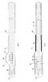
- FIG. 3illustrates a second, alternative embodiment of a sensor and guide wire assembly 41 according to the present invention, and shows that the sensor and guide wire assembly 41 comprises a sensor element 42 , which is arranged in a distal portion 43 of a sensor guide wire 44 .
- the sensor guide wire 44comprises a distal tip 45 , a distal coil spring 46 , a jacket or sleeve 47 , a flexible distal tube 48 , a core wire 49 , and a proximal tube 50 .
- the distal coil spring 46is attached to the distal tip 45 , and extends to the jacket 47 , which serves as a housing for the sensor element 42 .
- the flexible distal tube 48which also could be in the form of a coil spring, extends between the jacket 47 and the proximal tube 50 .
- the sensor element 42is mounted at a distal portion of the core wire 49 , and is through a window (not visible in FIG. 3 ) in the jacket 47 in fluid communication with the medium, e.g. blood, surrounding the sensor and guide wire assembly 41 .
- the sensor and guide wire assembly 41comprises further a number of signal transmitting cables 51 , the distal ends of which are electrically connected to the sensor element 42 and which extend along the core wire 49 to the proximal end portion of the sensor guide wire 44 , where each signal transmitting cable 51 is electrically connected to a conductive member 52 .
- the conductive members 52are electrically insulated from the core wire 49 as well as from each other by insulating members 53 , so as to form a male connector adapted for connection to a corresponding female connector of an external signal conditioning and display unit (not shown in FIG. 3 ).
- the jacket 47constitutes the only portion of the sensor guide wire 44 that has an enlarged diameter; and in particular the distal tip 45 and the distal coil spring 46 have both a diameter that is equal to the diameter of the flexible distal tube 48 and the proximal tube 50 . Due to its small diameter, the distal end portion (i.e. the coil spring 46 ) of the sensor guide wire 44 can be made very flexible, which can be advantageous in some medical applications, such as when the sensor guide wire is manoeuvred through extremely tortuous vessels.
- a sensor elementcan communicate wirelessly with an external unit.
- the physical requirements put on the sensor elementare considerably higher than in the wired case, because the sensor element must be able to receive energy via electromagnetic signals and communicate signals that are modulated in accordance with the sensed measurements.
- FIG. 4A schematic illustration of a wireless sensor and guide wire arrangement is shown in FIG. 4 .
- a sensor and guide wire assembly 61comprises a sensor element 62 , which is arranged in a distal portion 63 of a sensor guide wire 64 .
- the sensor guide wire 64comprises a distal tip 65 , a distal coil spring 66 , a jacket or sleeve 67 , a flexible distal tube 68 , a core wire 69 , and a proximal tube 70 .
- the distal coil spring 66is attached to the distal tip 65 , and extends to the jacket 67 , which serves as a housing for the sensor element 62 .
- the flexible distal tube 68which also could be in the form of a coil spring, extends between the jacket 67 and the proximal tube 70 .
- the sensor element 62is mounted to a distal portion of the core wire 69 , and is through a window (not visible in FIG. 4 ) in the jacket 67 in fluid communication with the medium, e.g. blood, surrounding the sensor and guide wire assembly 61 .
- the third embodiment discussed in conjunction with FIG. 4differs from the first and second embodiments of the present invention shown in FIG. 2 and FIG. 3 , respectively, in that there are no signal transmitting cables provided.
- the sensor element 62is instead capable of communicating with an external unit by electromagnetic signals, i.e. there is a wireless communication between the sensor element 62 and the external unit (not shown in FIG. 4 ).
- the physical requirements put on a sensor elementare considerably higher than in the wired case, since the sensor element must be able to receive energy from some type of carrier signals and then communicate signals that are modulated in accordance with the sensed measurement.
- Other types of wireless communicationsare also possible, e.g. that the sensor is powered by a battery and only output signals are received by an external unit.
- the more functionality that is incorporated in a sensor elementthe larger is the space required for the electronic circuits; and a sensor guide wire that provides a larger space for the sensor element is particularly advantageous for a wireless sensor and guide wire assembly.
- the general structure of the sensor guide wire 64is the same as in the first and second embodiments, i.e. the sensor guide wire 64 , like sensor guide wires 24 and 44 , respectively, comprises a core wire as well as proximal and distal tubes.
- the design of a sensor guide wirecan be significantly changed, due to the fact that signal transmitting cables can be dispensed with.
- a sensor and guide wire assembly 81 adapted for wireless communicationcomprises a sensor element 82 , which is arranged in a distal portion 83 of a sensor guide wire 84 .
- the sensor guide wire 84comprises a distal tip 85 , a distal coil spring 86 , and a housing 87 .
- the distal coil spring 86is attached to the distal tip 85 , and extends to the housing 87 , in which the sensor element 82 is disposed.
- the housing 87is formed integrally with the solid wire that constitutes the sensor guide wire 84 , and it can furthermore be noted that the housing 87 only projects out from a part of the circumference of the sensor guide wire 84 .
- the mechanical characteristics of the sensor guide wire 84can be improved, e.g. regarding torsional rigidity and bending stiffness.
- the present inventionis based on the observation that a catheter which is threaded onto a sensor guide wire never is advanced over the distal end of the sensor guide wire, and an enlarged distal sensor portion will consequently not prevent an effective use of a combination of a sensor guide wire and a catheter.
- a cathetercompletely lacks steering capability, i.e. the catheter must be guided to the site of interest by means of a guide wire.
- the enlarged sensor portionis preferably less than 2 mm, and in particular less than 1 mm.
- the enlarged portionmay be, for example, 10% larger (or 25%, or 50%, or 100% larger) than the non-enlarged portion.
- a sensor portion that is enlarged in comparison with the more proximal portions of a sensor guide wirecan be symmetrical, i.e. having a larger diameter than the diameters of the more proximal portions but with the same centre, or can be asymmetric or non-circular, i.e. where only a sector of the cross-section has a larger radius than the more proximal portions, an example of which was illustrated in conjunction with FIG.
- the important featurebeing that the sensor portion exhibits a maximal cross-sectional dimension that is larger than the maximal cross-sectional dimension of the guide wire portions located proximally of the sensor portion. Said cross-sectional dimension should be taken perpendicular to the central axis of the sensor guide wire. Consequently, the corresponding relationship and definition applies also for a distal end portion being smaller than the enlarged sensor portion, an example of which was discussed in conjunction with FIG. 3 .
Landscapes
- Health & Medical Sciences (AREA)
- Life Sciences & Earth Sciences (AREA)
- Animal Behavior & Ethology (AREA)
- Biophysics (AREA)
- Veterinary Medicine (AREA)
- Engineering & Computer Science (AREA)
- Biomedical Technology (AREA)
- Heart & Thoracic Surgery (AREA)
- Public Health (AREA)
- General Health & Medical Sciences (AREA)
- Surgery (AREA)
- Physics & Mathematics (AREA)
- Molecular Biology (AREA)
- Medical Informatics (AREA)
- Pathology (AREA)
- Hematology (AREA)
- Pulmonology (AREA)
- Anesthesiology (AREA)
- Measuring Pulse, Heart Rate, Blood Pressure Or Blood Flow (AREA)
- Media Introduction/Drainage Providing Device (AREA)
Abstract
Description
Claims (19)
Priority Applications (1)
| Application Number | Priority Date | Filing Date | Title |
|---|---|---|---|
| US11/607,120US7967761B2 (en) | 2006-12-01 | 2006-12-01 | Sensor and guide wire assembly |
Applications Claiming Priority (1)
| Application Number | Priority Date | Filing Date | Title |
|---|---|---|---|
| US11/607,120US7967761B2 (en) | 2006-12-01 | 2006-12-01 | Sensor and guide wire assembly |
Publications (2)
| Publication Number | Publication Date |
|---|---|
| US20080132806A1 US20080132806A1 (en) | 2008-06-05 |
| US7967761B2true US7967761B2 (en) | 2011-06-28 |
Family
ID=39476685
Family Applications (1)
| Application Number | Title | Priority Date | Filing Date |
|---|---|---|---|
| US11/607,120Expired - Fee RelatedUS7967761B2 (en) | 2006-12-01 | 2006-12-01 | Sensor and guide wire assembly |
Country Status (1)
| Country | Link |
|---|---|
| US (1) | US7967761B2 (en) |
Cited By (35)
| Publication number | Priority date | Publication date | Assignee | Title |
|---|---|---|---|---|
| US20100305476A1 (en)* | 2009-05-28 | 2010-12-02 | Ulbrich Precision Metals Limited | Guidewire sensor device and system |
| US20120172761A1 (en)* | 2010-12-29 | 2012-07-05 | Nimrod Meller | Medical device guidewire with a position sensor |
| US20140121648A1 (en)* | 2011-06-23 | 2014-05-01 | Koninklijke Philips N.V. | Composite fiber guidewires |
| US20140187982A1 (en)* | 2012-12-28 | 2014-07-03 | Volcano Corporation | Intravascular Devices Having Information Stored Thereon And/Or Wireless Communication Functionality, Including Associated Devices, Systems, And Methods |
| US20140276223A1 (en)* | 2013-03-15 | 2014-09-18 | St. Jude Medical Systems Ab | Sensor guide wire device and system including a sensor guide wire device |
| US20140288444A1 (en)* | 2011-11-09 | 2014-09-25 | St. Jude Medical Systems Ab | Sensor guide wire |
| US9149230B2 (en) | 2011-10-28 | 2015-10-06 | Three Rivers Cardiovascular Systems Inc. | Apparatus, system and methods for measuring a blood pressure gradient |
| US9877660B2 (en) | 2013-11-14 | 2018-01-30 | Medtronic Vascular Galway | Systems and methods for determining fractional flow reserve without adenosine or other pharmalogical agent |
| US9913585B2 (en) | 2014-01-15 | 2018-03-13 | Medtronic Vascular, Inc. | Catheter for providing vascular pressure measurements |
| US20180263509A1 (en)* | 2012-08-31 | 2018-09-20 | Koninklijke Philips N.V. | Mounting Structures for Components of Intravascular Devices |
| US10130269B2 (en) | 2013-11-14 | 2018-11-20 | Medtronic Vascular, Inc | Dual lumen catheter for providing a vascular pressure measurement |
| US10194812B2 (en) | 2014-12-12 | 2019-02-05 | Medtronic Vascular, Inc. | System and method of integrating a fractional flow reserve device with a conventional hemodynamic monitoring system |
| US10201284B2 (en) | 2014-06-16 | 2019-02-12 | Medtronic Vascular Inc. | Pressure measuring catheter having reduced error from bending stresses |
| US10258240B1 (en) | 2014-11-24 | 2019-04-16 | Vascular Imaging Corporation | Optical fiber pressure sensor |
| US10307070B2 (en) | 2014-04-04 | 2019-06-04 | St. Jude Medical Coordination Center Bvba | Intravascular pressure and flow data diagnostic systems, devices, and methods |
| US10327645B2 (en) | 2013-10-04 | 2019-06-25 | Vascular Imaging Corporation | Imaging techniques using an imaging guidewire |
| US10463259B2 (en) | 2011-10-28 | 2019-11-05 | Three Rivers Cardiovascular Systems Inc. | System and apparatus comprising a multi-sensor catheter for right heart and pulmonary artery catheterization |
| US10506934B2 (en) | 2012-05-25 | 2019-12-17 | Phyzhon Health Inc. | Optical fiber pressure sensor |
| US10537255B2 (en) | 2013-11-21 | 2020-01-21 | Phyzhon Health Inc. | Optical fiber pressure sensor |
| US10648918B2 (en) | 2011-08-03 | 2020-05-12 | Lightlab Imaging, Inc. | Systems, methods and apparatus for determining a fractional flow reserve (FFR) based on the minimum lumen area (MLA) and the constant |
| US10646122B2 (en) | 2017-04-28 | 2020-05-12 | Medtronic Vascular, Inc. | FFR catheter with covered distal pressure sensor and method of manufacture |
| US10702170B2 (en) | 2013-07-01 | 2020-07-07 | Zurich Medical Corporation | Apparatus and method for intravascular measurements |
| US10722175B2 (en) | 2014-07-13 | 2020-07-28 | Hemocath Ltd. | System and apparatus comprising a multisensor guidewire for use in interventional cardiology |
| US10835183B2 (en) | 2013-07-01 | 2020-11-17 | Zurich Medical Corporation | Apparatus and method for intravascular measurements |
| US10973418B2 (en) | 2014-06-16 | 2021-04-13 | Medtronic Vascular, Inc. | Microcatheter sensor design for minimizing profile and impact of wire strain on sensor |
| US11185244B2 (en) | 2018-08-13 | 2021-11-30 | Medtronic Vascular, Inc. | FFR catheter with suspended pressure sensor |
| US11219741B2 (en) | 2017-08-09 | 2022-01-11 | Medtronic Vascular, Inc. | Collapsible catheter and method for calculating fractional flow reserve |
| US11235124B2 (en) | 2017-08-09 | 2022-02-01 | Medtronic Vascular, Inc. | Collapsible catheter and method for calculating fractional flow reserve |
| US11241154B2 (en) | 2011-05-31 | 2022-02-08 | Lightlab Imaging, Inc. | Multimodal imaging system, apparatus, and methods |
| US11272850B2 (en) | 2016-08-09 | 2022-03-15 | Medtronic Vascular, Inc. | Catheter and method for calculating fractional flow reserve |
| US11272847B2 (en) | 2016-10-14 | 2022-03-15 | Hemocath Ltd. | System and apparatus comprising a multi-sensor catheter for right heart and pulmonary artery catheterization |
| US11330994B2 (en) | 2017-03-08 | 2022-05-17 | Medtronic Vascular, Inc. | Reduced profile FFR catheter |
| US11330989B2 (en) | 2014-06-16 | 2022-05-17 | Medtronic Vascular, Inc. | Microcatheter sensor design for mounting sensor to minimize induced strain |
| US12383246B2 (en) | 2020-10-12 | 2025-08-12 | Abbott Cardiovascular Systems, Inc. | Vessel closure device with improved safety and tract hemostasis |
| US12402797B2 (en) | 2019-09-30 | 2025-09-02 | Hemocath Ltd. | Multi-sensor catheter for right heart and pulmonary artery catheterization |
Families Citing this family (10)
| Publication number | Priority date | Publication date | Assignee | Title |
|---|---|---|---|---|
| US7472601B1 (en)* | 2007-09-21 | 2009-01-06 | Radi Medical Systems Ab | Sensor for intravascular measurements within a living body |
| WO2011092202A1 (en)* | 2010-01-29 | 2011-08-04 | St Jude Medical Systems Ab | Medical guide wire assembly |
| SE1050741A1 (en)* | 2010-07-06 | 2012-01-07 | St Jude Medical Systems Ab | Sensor element |
| CN103391742B (en)* | 2011-01-30 | 2015-12-09 | 引导介入公司 | A system for detecting blood pressure using a pressure-sensing guidewire |
| US20130109980A1 (en)* | 2011-11-01 | 2013-05-02 | Tat-Jin Teo | Systems and methods for a wireless vascular pressure measurement device |
| US9364640B2 (en) | 2012-05-07 | 2016-06-14 | St. Jude Medical Atrial Fibrillation Division, Inc. | Medical device guidewire with helical cutout and coating |
| JP2016501674A (en)* | 2012-12-28 | 2016-01-21 | ヴォルカノ コーポレイションVolcano Corporation | Intravascular device, system, and method with information stored in the intravascular device and / or wireless communication capability with associated devices |
| US20140276117A1 (en)* | 2013-03-15 | 2014-09-18 | Volcano Corporation | Intravascular Devices, Systems, and Methods |
| JP6945451B2 (en)* | 2015-04-14 | 2021-10-06 | コーニンクレッカ フィリップス エヌ ヴェKoninklijke Philips N.V. | Intravascular devices, systems and methods with a polymer jacket formed around a communication line wrapped around a core member. |
| CN106388800A (en)* | 2016-02-19 | 2017-02-15 | 深圳北芯生命科技有限公司 | Catheter capable of measuring pressure in blood vessel |
Citations (27)
| Publication number | Priority date | Publication date | Assignee | Title |
|---|---|---|---|---|
| US1344758A (en) | 1919-09-22 | 1920-06-29 | Donnelly John | Window-screen |
| US4463336A (en) | 1981-12-28 | 1984-07-31 | United Technologies Corporation | Ultra-thin microelectronic pressure sensors |
| US5029479A (en) | 1988-08-15 | 1991-07-09 | Imo Industries, Inc. | Differential pressure transducers |
| US5132658A (en) | 1990-04-19 | 1992-07-21 | Sensym, Inc. | Micromachined silicon potentiometer responsive to pressure |
| US5226423A (en) | 1990-07-11 | 1993-07-13 | Radi Medical Systems Ab | Sensor guide construction and use thereof |
| US6106476A (en)* | 1994-09-02 | 2000-08-22 | Endosonics Corporation | Ultra miniature pressure sensor and guide wire using the same and method |
| US6112598A (en) | 1995-06-22 | 2000-09-05 | Radi Medical Systems Ab | Pressure sensor and guide wire assembly for biological pressure measurements |
| US6182513B1 (en) | 1998-12-23 | 2001-02-06 | Radi Medical Systems Ab | Resonant sensor and method of making a pressure sensor comprising a resonant beam structure |
| US6245026B1 (en)* | 1996-07-29 | 2001-06-12 | Farallon Medsystems, Inc. | Thermography catheter |
| US6279402B1 (en) | 1998-08-10 | 2001-08-28 | Applied Materials, Inc. | Device for measuring pressure in a chamber |
| US6312380B1 (en)* | 1998-12-23 | 2001-11-06 | Radi Medical Systems Ab | Method and sensor for wireless measurement of physiological variables |
| US6343514B1 (en) | 1996-01-30 | 2002-02-05 | Radi Medical Systems Ab | Combined flow, pressure and temperature sensor |
| US6461301B2 (en) | 2000-03-21 | 2002-10-08 | Radi Medical Systems Ab | Resonance based pressure transducer system |
| US6495908B2 (en) | 2001-04-12 | 2002-12-17 | Siliconware Precision Industries, Co., Ltd.. | Multi-chip semiconductor package |
| US20030028128A1 (en) | 2001-06-15 | 2003-02-06 | Radi Medical Systems Ab | Electrically conductive coaxial guide wire |
| US6575623B2 (en)* | 2000-11-10 | 2003-06-10 | Cardiostream, Inc. | Guide wire having extendable contact sensors for measuring temperature of vessel walls |
| US6615067B2 (en) | 2000-03-21 | 2003-09-02 | Radi Medical Systems Ab | Method and device for measuring physical characteristics in a body |
| US6692446B2 (en) | 2000-03-21 | 2004-02-17 | Radi Medical Systems Ab | Passive biotelemetry |
| US20040068203A1 (en)* | 2002-10-03 | 2004-04-08 | Scimed Life Systems, Inc. | Sensing pressure |
| US20040225232A1 (en) | 2003-05-09 | 2004-11-11 | Radi Medical Systems Ab | Sensor guide wire |
| US20050000294A1 (en) | 2003-07-02 | 2005-01-06 | Radi Medical Systems Ab | Sensor and guide wire assembly |
| US20050011272A1 (en) | 2003-07-18 | 2005-01-20 | Radi Medical Systems Ab | Sensor and guide wire assembly |
| EP1530028A1 (en) | 2003-10-16 | 2005-05-11 | Festo Corporation | Multiple technology flow sensor |
| US20050268724A1 (en) | 2004-06-07 | 2005-12-08 | Radi Medical Systems Ab | Sensor and guide wire assembly |
| EP1479407B1 (en) | 1998-12-23 | 2006-03-01 | Radi Medical Systems Ab | Sensor and guide wire assembly |
| US20060079740A1 (en)* | 2000-05-15 | 2006-04-13 | Silver James H | Sensors for detecting substances indicative of stroke, ischemia, or myocardial infarction |
| US20070078318A1 (en)* | 2005-09-30 | 2007-04-05 | Carl Kling | Mucosal sensor for the assessment of tissue and blood constituents and technique for using the same |
Family Cites Families (1)
| Publication number | Priority date | Publication date | Assignee | Title |
|---|---|---|---|---|
| US6611365B2 (en)* | 2001-03-20 | 2003-08-26 | Imation Corp. | Thermoplastic substrates for holographic data storage media |
- 2006
- 2006-12-01USUS11/607,120patent/US7967761B2/ennot_activeExpired - Fee Related
Patent Citations (34)
| Publication number | Priority date | Publication date | Assignee | Title |
|---|---|---|---|---|
| US1344758A (en) | 1919-09-22 | 1920-06-29 | Donnelly John | Window-screen |
| US4463336A (en) | 1981-12-28 | 1984-07-31 | United Technologies Corporation | Ultra-thin microelectronic pressure sensors |
| US5029479A (en) | 1988-08-15 | 1991-07-09 | Imo Industries, Inc. | Differential pressure transducers |
| US5132658A (en) | 1990-04-19 | 1992-07-21 | Sensym, Inc. | Micromachined silicon potentiometer responsive to pressure |
| US5226423A (en) | 1990-07-11 | 1993-07-13 | Radi Medical Systems Ab | Sensor guide construction and use thereof |
| USRE35648E (en) | 1990-07-11 | 1997-11-04 | Radi Medical Systems Ab | Sensor guide construction and use thereof |
| US6106476A (en)* | 1994-09-02 | 2000-08-22 | Endosonics Corporation | Ultra miniature pressure sensor and guide wire using the same and method |
| US20030018273A1 (en) | 1994-09-02 | 2003-01-23 | Jomed Inc. | Guidewire with pressure and temperature sensing capabilities |
| US6112598A (en) | 1995-06-22 | 2000-09-05 | Radi Medical Systems Ab | Pressure sensor and guide wire assembly for biological pressure measurements |
| US6167763B1 (en) | 1995-06-22 | 2001-01-02 | Radi Medical Systems Ab | Pressure sensor and guide wire assembly for biological pressure measurements |
| US6343514B1 (en) | 1996-01-30 | 2002-02-05 | Radi Medical Systems Ab | Combined flow, pressure and temperature sensor |
| US6245026B1 (en)* | 1996-07-29 | 2001-06-12 | Farallon Medsystems, Inc. | Thermography catheter |
| US6279402B1 (en) | 1998-08-10 | 2001-08-28 | Applied Materials, Inc. | Device for measuring pressure in a chamber |
| US6312380B1 (en)* | 1998-12-23 | 2001-11-06 | Radi Medical Systems Ab | Method and sensor for wireless measurement of physiological variables |
| US20020013527A1 (en) | 1998-12-23 | 2002-01-31 | Bertil Hoek | Method and sensor for wireless measurement of physiological variables |
| EP1479407B1 (en) | 1998-12-23 | 2006-03-01 | Radi Medical Systems Ab | Sensor and guide wire assembly |
| US6182513B1 (en) | 1998-12-23 | 2001-02-06 | Radi Medical Systems Ab | Resonant sensor and method of making a pressure sensor comprising a resonant beam structure |
| US6461301B2 (en) | 2000-03-21 | 2002-10-08 | Radi Medical Systems Ab | Resonance based pressure transducer system |
| US6615067B2 (en) | 2000-03-21 | 2003-09-02 | Radi Medical Systems Ab | Method and device for measuring physical characteristics in a body |
| US6692446B2 (en) | 2000-03-21 | 2004-02-17 | Radi Medical Systems Ab | Passive biotelemetry |
| US20060079740A1 (en)* | 2000-05-15 | 2006-04-13 | Silver James H | Sensors for detecting substances indicative of stroke, ischemia, or myocardial infarction |
| US6575623B2 (en)* | 2000-11-10 | 2003-06-10 | Cardiostream, Inc. | Guide wire having extendable contact sensors for measuring temperature of vessel walls |
| US6495908B2 (en) | 2001-04-12 | 2002-12-17 | Siliconware Precision Industries, Co., Ltd.. | Multi-chip semiconductor package |
| US7011636B2 (en)* | 2001-06-15 | 2006-03-14 | Radi Medical Systems Ab | Electrically conductive coaxial guide wire |
| US20030028128A1 (en) | 2001-06-15 | 2003-02-06 | Radi Medical Systems Ab | Electrically conductive coaxial guide wire |
| US20040068203A1 (en)* | 2002-10-03 | 2004-04-08 | Scimed Life Systems, Inc. | Sensing pressure |
| US20040225232A1 (en) | 2003-05-09 | 2004-11-11 | Radi Medical Systems Ab | Sensor guide wire |
| US20050000294A1 (en) | 2003-07-02 | 2005-01-06 | Radi Medical Systems Ab | Sensor and guide wire assembly |
| US20050011272A1 (en) | 2003-07-18 | 2005-01-20 | Radi Medical Systems Ab | Sensor and guide wire assembly |
| EP1530028A1 (en) | 2003-10-16 | 2005-05-11 | Festo Corporation | Multiple technology flow sensor |
| US20050268724A1 (en) | 2004-06-07 | 2005-12-08 | Radi Medical Systems Ab | Sensor and guide wire assembly |
| US20060207335A1 (en) | 2005-02-24 | 2006-09-21 | Radi Medical Systems Ab | Sensor and guide wire assembly |
| US7343811B2 (en) | 2005-02-24 | 2008-03-18 | Radi Medical Systems Ab | Sensor and guide wire assembly |
| US20070078318A1 (en)* | 2005-09-30 | 2007-04-05 | Carl Kling | Mucosal sensor for the assessment of tissue and blood constituents and technique for using the same |
Non-Patent Citations (4)
| Title |
|---|
| C. Li et al., "Polymer Flip-Chip Bonding of Pressure Sensors on Flexible Kapton Film for Neonatal Catheters," Proceedings of IEEE, Oct. 24-27, 2004, pp. 749-752. |
| L. Smith, U.S. PTO Non-Final Office Action, U.S. Appl. No. 11/359,761, dated Apr. 20, 2007, 9 pgs. |
| L. Smith, U.S. PTO Notice of Allowance, U.S. Appl. No. 11/359,761, dated Nov. 7, 2007, 4 pgs. |
| Sauser et al., "Pressure Microsensing Catheters for Neonatal Care," Sensors, Proceedings of IEEE, Oct. 24-27, 2004; pp. 1476-1479. |
Cited By (55)
| Publication number | Priority date | Publication date | Assignee | Title |
|---|---|---|---|---|
| US20100305476A1 (en)* | 2009-05-28 | 2010-12-02 | Ulbrich Precision Metals Limited | Guidewire sensor device and system |
| US10028705B2 (en) | 2010-12-29 | 2018-07-24 | St. Jude Medical International Holding S.À R.L. | Medical device guidewire with a position sensor |
| US20120172761A1 (en)* | 2010-12-29 | 2012-07-05 | Nimrod Meller | Medical device guidewire with a position sensor |
| US8764683B2 (en)* | 2010-12-29 | 2014-07-01 | Mediguide Ltd. | Medical device guidewire with a position sensor |
| US11241154B2 (en) | 2011-05-31 | 2022-02-08 | Lightlab Imaging, Inc. | Multimodal imaging system, apparatus, and methods |
| US20140121648A1 (en)* | 2011-06-23 | 2014-05-01 | Koninklijke Philips N.V. | Composite fiber guidewires |
| US10035002B2 (en)* | 2011-06-23 | 2018-07-31 | Koninklijke Philips N.V. | Composite fiber guidewires |
| US10648918B2 (en) | 2011-08-03 | 2020-05-12 | Lightlab Imaging, Inc. | Systems, methods and apparatus for determining a fractional flow reserve (FFR) based on the minimum lumen area (MLA) and the constant |
| US11197619B2 (en) | 2011-10-28 | 2021-12-14 | Three Rivers Cardiovascular Systems Inc. | System and apparatus comprising a multi-sensor catheter for right heart and pulmonary artery catheterization |
| US9149230B2 (en) | 2011-10-28 | 2015-10-06 | Three Rivers Cardiovascular Systems Inc. | Apparatus, system and methods for measuring a blood pressure gradient |
| US10463259B2 (en) | 2011-10-28 | 2019-11-05 | Three Rivers Cardiovascular Systems Inc. | System and apparatus comprising a multi-sensor catheter for right heart and pulmonary artery catheterization |
| US9504392B2 (en) | 2011-10-28 | 2016-11-29 | Three Rivers Cardiovascular Systems Inc. | Apparatus, system and methods for measuring a blood pressure gradient |
| US20140288444A1 (en)* | 2011-11-09 | 2014-09-25 | St. Jude Medical Systems Ab | Sensor guide wire |
| US9044202B2 (en)* | 2011-11-09 | 2015-06-02 | St. Jude Medical Coordination Center Bvba | Sensor guide wire |
| US11172833B2 (en) | 2012-05-25 | 2021-11-16 | Phyzhon Health Inc. | Optical fiber pressure sensor guidewire |
| US10506934B2 (en) | 2012-05-25 | 2019-12-17 | Phyzhon Health Inc. | Optical fiber pressure sensor |
| US20180263509A1 (en)* | 2012-08-31 | 2018-09-20 | Koninklijke Philips N.V. | Mounting Structures for Components of Intravascular Devices |
| US11759113B2 (en)* | 2012-08-31 | 2023-09-19 | Philips Image Guided Therapy Corporation | Mounting structures for components of intravascular devices |
| US20240008755A1 (en)* | 2012-08-31 | 2024-01-11 | Philips Image Guided Therapy Corporation | Mounting structures for components of intravascular devices |
| US20210177280A1 (en)* | 2012-08-31 | 2021-06-17 | Philips Image Guided Therapy Corporation | Mounting structures for components of intravascular devices |
| US10932678B2 (en)* | 2012-08-31 | 2021-03-02 | Philips Image Guided Therapy Corporation | Mounting structures for components of intravascular devices |
| US12318174B2 (en)* | 2012-08-31 | 2025-06-03 | Philips Image Guided Therapy Corporation | Mounting structures for components of intravascular devices |
| US20140187982A1 (en)* | 2012-12-28 | 2014-07-03 | Volcano Corporation | Intravascular Devices Having Information Stored Thereon And/Or Wireless Communication Functionality, Including Associated Devices, Systems, And Methods |
| US10117620B2 (en)* | 2013-03-15 | 2018-11-06 | St. Jude Medical Coordination Center Bvba | Sensor guide wire device and system including a sensor guide wire device |
| US20140276223A1 (en)* | 2013-03-15 | 2014-09-18 | St. Jude Medical Systems Ab | Sensor guide wire device and system including a sensor guide wire device |
| US10702170B2 (en) | 2013-07-01 | 2020-07-07 | Zurich Medical Corporation | Apparatus and method for intravascular measurements |
| US11471061B2 (en) | 2013-07-01 | 2022-10-18 | Zurich Medical Corporation | Apparatus and method for intravascular measurements |
| US10835183B2 (en) | 2013-07-01 | 2020-11-17 | Zurich Medical Corporation | Apparatus and method for intravascular measurements |
| US10327645B2 (en) | 2013-10-04 | 2019-06-25 | Vascular Imaging Corporation | Imaging techniques using an imaging guidewire |
| US11298026B2 (en) | 2013-10-04 | 2022-04-12 | Phyzhon Health Inc. | Imaging techniques using an imaging guidewire |
| US10130269B2 (en) | 2013-11-14 | 2018-11-20 | Medtronic Vascular, Inc | Dual lumen catheter for providing a vascular pressure measurement |
| US9877660B2 (en) | 2013-11-14 | 2018-01-30 | Medtronic Vascular Galway | Systems and methods for determining fractional flow reserve without adenosine or other pharmalogical agent |
| US11696692B2 (en) | 2013-11-21 | 2023-07-11 | Phyzhon Health Inc. | Optical fiber pressure sensor |
| US10537255B2 (en) | 2013-11-21 | 2020-01-21 | Phyzhon Health Inc. | Optical fiber pressure sensor |
| US9913585B2 (en) | 2014-01-15 | 2018-03-13 | Medtronic Vascular, Inc. | Catheter for providing vascular pressure measurements |
| US10307070B2 (en) | 2014-04-04 | 2019-06-04 | St. Jude Medical Coordination Center Bvba | Intravascular pressure and flow data diagnostic systems, devices, and methods |
| US11559218B2 (en) | 2014-04-04 | 2023-01-24 | St. Jude Medical Coordination Center Bvba | Intravascular pressure and flow data diagnostic systems, devices, and methods |
| US12053265B2 (en) | 2014-06-16 | 2024-08-06 | Medtronic Vascular, Inc. | Microcatheter sensor design for mounting sensor to minimize induced strain |
| US11701012B2 (en) | 2014-06-16 | 2023-07-18 | Medtronic Vascular, Inc. | Microcatheter sensor design for minimizing profile and impact of wire strain on sensor |
| US11850030B2 (en) | 2014-06-16 | 2023-12-26 | Medtronic Vascular, Inc. | Pressure measuring catheter having reduced error from bending stresses |
| US10201284B2 (en) | 2014-06-16 | 2019-02-12 | Medtronic Vascular Inc. | Pressure measuring catheter having reduced error from bending stresses |
| US10973418B2 (en) | 2014-06-16 | 2021-04-13 | Medtronic Vascular, Inc. | Microcatheter sensor design for minimizing profile and impact of wire strain on sensor |
| US11330989B2 (en) | 2014-06-16 | 2022-05-17 | Medtronic Vascular, Inc. | Microcatheter sensor design for mounting sensor to minimize induced strain |
| US10722175B2 (en) | 2014-07-13 | 2020-07-28 | Hemocath Ltd. | System and apparatus comprising a multisensor guidewire for use in interventional cardiology |
| US10258240B1 (en) | 2014-11-24 | 2019-04-16 | Vascular Imaging Corporation | Optical fiber pressure sensor |
| US10194812B2 (en) | 2014-12-12 | 2019-02-05 | Medtronic Vascular, Inc. | System and method of integrating a fractional flow reserve device with a conventional hemodynamic monitoring system |
| US11272850B2 (en) | 2016-08-09 | 2022-03-15 | Medtronic Vascular, Inc. | Catheter and method for calculating fractional flow reserve |
| US11272847B2 (en) | 2016-10-14 | 2022-03-15 | Hemocath Ltd. | System and apparatus comprising a multi-sensor catheter for right heart and pulmonary artery catheterization |
| US11330994B2 (en) | 2017-03-08 | 2022-05-17 | Medtronic Vascular, Inc. | Reduced profile FFR catheter |
| US10646122B2 (en) | 2017-04-28 | 2020-05-12 | Medtronic Vascular, Inc. | FFR catheter with covered distal pressure sensor and method of manufacture |
| US11235124B2 (en) | 2017-08-09 | 2022-02-01 | Medtronic Vascular, Inc. | Collapsible catheter and method for calculating fractional flow reserve |
| US11219741B2 (en) | 2017-08-09 | 2022-01-11 | Medtronic Vascular, Inc. | Collapsible catheter and method for calculating fractional flow reserve |
| US11185244B2 (en) | 2018-08-13 | 2021-11-30 | Medtronic Vascular, Inc. | FFR catheter with suspended pressure sensor |
| US12402797B2 (en) | 2019-09-30 | 2025-09-02 | Hemocath Ltd. | Multi-sensor catheter for right heart and pulmonary artery catheterization |
| US12383246B2 (en) | 2020-10-12 | 2025-08-12 | Abbott Cardiovascular Systems, Inc. | Vessel closure device with improved safety and tract hemostasis |
Also Published As
| Publication number | Publication date |
|---|---|
| US20080132806A1 (en) | 2008-06-05 |
Similar Documents
| Publication | Publication Date | Title |
|---|---|---|
| US7967761B2 (en) | Sensor and guide wire assembly | |
| EP1927316B1 (en) | Sensor and guide wire assembly | |
| US11998356B2 (en) | Sensor jacket | |
| EP1849409B1 (en) | Sensor and guidewire assembly | |
| JP5676564B2 (en) | Sensor guide wire | |
| US10329145B2 (en) | Capacitive intravascular pressure-sensing devices and associated systems and methods | |
| US8038628B2 (en) | Torque device for a sensor guide wire | |
| US20070255145A1 (en) | Sensor and guide wire assembly | |
| EP2209419B1 (en) | Sensor guide wire | |
| US10314541B2 (en) | Sensor guide wire | |
| JP6290250B2 (en) | Pressure sensing endovascular device, system, and method | |
| US9763622B2 (en) | Sensor element with an insulation layer | |
| US9044202B2 (en) | Sensor guide wire |
Legal Events
| Date | Code | Title | Description |
|---|---|---|---|
| AS | Assignment | Owner name:RADI MEDICAL SYSTEMS AB, SWEDEN Free format text:ASSIGNMENT OF ASSIGNORS INTEREST;ASSIGNOR:SMITH, LEIF;REEL/FRAME:018896/0962 Effective date:20070109 | |
| FEPP | Fee payment procedure | Free format text:PAYOR NUMBER ASSIGNED (ORIGINAL EVENT CODE: ASPN); ENTITY STATUS OF PATENT OWNER: LARGE ENTITY | |
| STCF | Information on status: patent grant | Free format text:PATENTED CASE | |
| FPAY | Fee payment | Year of fee payment:4 | |
| AS | Assignment | Owner name:ST. JUDE MEDICAL SYSTEMS AB, SWEDEN Free format text:CHANGE OF NAME;ASSIGNOR:RADI MEDICAL SYSTEMS AB;REEL/FRAME:034796/0153 Effective date:20091127 | |
| AS | Assignment | Owner name:ST. JUDE MEDICAL COORDINATION CENTER BVBA, BELGIUM Free format text:ASSIGNMENT OF ASSIGNORS INTEREST;ASSIGNOR:ST. JUDE MEDICAL SYSTEMS AB;REEL/FRAME:035169/0705 Effective date:20140923 | |
| FEPP | Fee payment procedure | Free format text:MAINTENANCE FEE REMINDER MAILED (ORIGINAL EVENT CODE: REM.); ENTITY STATUS OF PATENT OWNER: LARGE ENTITY | |
| LAPS | Lapse for failure to pay maintenance fees | Free format text:PATENT EXPIRED FOR FAILURE TO PAY MAINTENANCE FEES (ORIGINAL EVENT CODE: EXP.); ENTITY STATUS OF PATENT OWNER: LARGE ENTITY | |
| STCH | Information on status: patent discontinuation | Free format text:PATENT EXPIRED DUE TO NONPAYMENT OF MAINTENANCE FEES UNDER 37 CFR 1.362 | |
| FP | Lapsed due to failure to pay maintenance fee | Effective date:20190628 |