US7967462B2 - Backlight assembly for liquid crystal display apparatus having inclined light emmitting elements - Google Patents
Backlight assembly for liquid crystal display apparatus having inclined light emmitting elementsDownload PDFInfo
- Publication number
- US7967462B2 US7967462B2US12/361,849US36184909AUS7967462B2US 7967462 B2US7967462 B2US 7967462B2US 36184909 AUS36184909 AUS 36184909AUS 7967462 B2US7967462 B2US 7967462B2
- Authority
- US
- United States
- Prior art keywords
- liquid crystal
- light
- crystal display
- light emitting
- optical guide
- Prior art date
- Legal status (The legal status is an assumption and is not a legal conclusion. Google has not performed a legal analysis and makes no representation as to the accuracy of the status listed.)
- Active
Links
Images

Classifications
- G—PHYSICS
- G02—OPTICS
- G02F—OPTICAL DEVICES OR ARRANGEMENTS FOR THE CONTROL OF LIGHT BY MODIFICATION OF THE OPTICAL PROPERTIES OF THE MEDIA OF THE ELEMENTS INVOLVED THEREIN; NON-LINEAR OPTICS; FREQUENCY-CHANGING OF LIGHT; OPTICAL LOGIC ELEMENTS; OPTICAL ANALOGUE/DIGITAL CONVERTERS
- G02F1/00—Devices or arrangements for the control of the intensity, colour, phase, polarisation or direction of light arriving from an independent light source, e.g. switching, gating or modulating; Non-linear optics
- G02F1/01—Devices or arrangements for the control of the intensity, colour, phase, polarisation or direction of light arriving from an independent light source, e.g. switching, gating or modulating; Non-linear optics for the control of the intensity, phase, polarisation or colour
- G02F1/13—Devices or arrangements for the control of the intensity, colour, phase, polarisation or direction of light arriving from an independent light source, e.g. switching, gating or modulating; Non-linear optics for the control of the intensity, phase, polarisation or colour based on liquid crystals, e.g. single liquid crystal display cells
- G02F1/133—Constructional arrangements; Operation of liquid crystal cells; Circuit arrangements
- G02F1/1333—Constructional arrangements; Manufacturing methods
- G02F1/1335—Structural association of cells with optical devices, e.g. polarisers or reflectors
- G02F1/1336—Illuminating devices
- G02F1/133602—Direct backlight
- G02F1/133608—Direct backlight including particular frames or supporting means
- G—PHYSICS
- G02—OPTICS
- G02F—OPTICAL DEVICES OR ARRANGEMENTS FOR THE CONTROL OF LIGHT BY MODIFICATION OF THE OPTICAL PROPERTIES OF THE MEDIA OF THE ELEMENTS INVOLVED THEREIN; NON-LINEAR OPTICS; FREQUENCY-CHANGING OF LIGHT; OPTICAL LOGIC ELEMENTS; OPTICAL ANALOGUE/DIGITAL CONVERTERS
- G02F1/00—Devices or arrangements for the control of the intensity, colour, phase, polarisation or direction of light arriving from an independent light source, e.g. switching, gating or modulating; Non-linear optics
- G02F1/01—Devices or arrangements for the control of the intensity, colour, phase, polarisation or direction of light arriving from an independent light source, e.g. switching, gating or modulating; Non-linear optics for the control of the intensity, phase, polarisation or colour
- G02F1/13—Devices or arrangements for the control of the intensity, colour, phase, polarisation or direction of light arriving from an independent light source, e.g. switching, gating or modulating; Non-linear optics for the control of the intensity, phase, polarisation or colour based on liquid crystals, e.g. single liquid crystal display cells
- G02F1/133—Constructional arrangements; Operation of liquid crystal cells; Circuit arrangements
- G02F1/1333—Constructional arrangements; Manufacturing methods
- G02F1/1335—Structural association of cells with optical devices, e.g. polarisers or reflectors
- G02F1/1336—Illuminating devices
- G02F1/133602—Direct backlight
- G02F1/133603—Direct backlight with LEDs
- G—PHYSICS
- G02—OPTICS
- G02F—OPTICAL DEVICES OR ARRANGEMENTS FOR THE CONTROL OF LIGHT BY MODIFICATION OF THE OPTICAL PROPERTIES OF THE MEDIA OF THE ELEMENTS INVOLVED THEREIN; NON-LINEAR OPTICS; FREQUENCY-CHANGING OF LIGHT; OPTICAL LOGIC ELEMENTS; OPTICAL ANALOGUE/DIGITAL CONVERTERS
- G02F1/00—Devices or arrangements for the control of the intensity, colour, phase, polarisation or direction of light arriving from an independent light source, e.g. switching, gating or modulating; Non-linear optics
- G02F1/01—Devices or arrangements for the control of the intensity, colour, phase, polarisation or direction of light arriving from an independent light source, e.g. switching, gating or modulating; Non-linear optics for the control of the intensity, phase, polarisation or colour
- G02F1/13—Devices or arrangements for the control of the intensity, colour, phase, polarisation or direction of light arriving from an independent light source, e.g. switching, gating or modulating; Non-linear optics for the control of the intensity, phase, polarisation or colour based on liquid crystals, e.g. single liquid crystal display cells
- G02F1/133—Constructional arrangements; Operation of liquid crystal cells; Circuit arrangements
- G02F1/1333—Constructional arrangements; Manufacturing methods
- G02F1/1335—Structural association of cells with optical devices, e.g. polarisers or reflectors
- G02F1/1336—Illuminating devices
- G02F1/133602—Direct backlight
- G02F1/133606—Direct backlight including a specially adapted diffusing, scattering or light controlling members
- G02F1/133607—Direct backlight including a specially adapted diffusing, scattering or light controlling members the light controlling member including light directing or refracting elements, e.g. prisms or lenses
- G—PHYSICS
- G02—OPTICS
- G02F—OPTICAL DEVICES OR ARRANGEMENTS FOR THE CONTROL OF LIGHT BY MODIFICATION OF THE OPTICAL PROPERTIES OF THE MEDIA OF THE ELEMENTS INVOLVED THEREIN; NON-LINEAR OPTICS; FREQUENCY-CHANGING OF LIGHT; OPTICAL LOGIC ELEMENTS; OPTICAL ANALOGUE/DIGITAL CONVERTERS
- G02F1/00—Devices or arrangements for the control of the intensity, colour, phase, polarisation or direction of light arriving from an independent light source, e.g. switching, gating or modulating; Non-linear optics
- G02F1/01—Devices or arrangements for the control of the intensity, colour, phase, polarisation or direction of light arriving from an independent light source, e.g. switching, gating or modulating; Non-linear optics for the control of the intensity, phase, polarisation or colour
- G02F1/13—Devices or arrangements for the control of the intensity, colour, phase, polarisation or direction of light arriving from an independent light source, e.g. switching, gating or modulating; Non-linear optics for the control of the intensity, phase, polarisation or colour based on liquid crystals, e.g. single liquid crystal display cells
- G02F1/133—Constructional arrangements; Operation of liquid crystal cells; Circuit arrangements
- G02F1/1333—Constructional arrangements; Manufacturing methods
- G02F1/1335—Structural association of cells with optical devices, e.g. polarisers or reflectors
- G02F1/1336—Illuminating devices
- G02F1/133602—Direct backlight
- G02F1/133611—Direct backlight including means for improving the brightness uniformity
Definitions
- the present inventionrelates to a backlight system for a liquid crystal display apparatus, and more particularly to a thin and low-cost liquid crystal display apparatus using light emitting diodes as a backlight and efficiently irradiating light to a liquid crystal display.
- an LEDis generally a point light source having a predetermined directivity, it is necessary for light emitted from LED's to be irradiated to a liquid crystal display as a uniform area light source.
- JP-A-2007-42404discloses techniques of uniformizing a luminance, in the side light type in which light from LED light sources is made to enter from the side plane of an optical guide plate disposed under a liquid crystal panel, by forming a prism as a reflection surface on the optical guide plate, and by gradually changing a prism inclination angle in accordance with a distance from an optical incidence surface.
- JP-A-2006-344409discloses techniques of improving luminance distribution, in a just-under type illumination apparatus for radiating illumination light from the back surface of a liquid crystal display, by forming a concentric concave/convex prism structure on an optical control plate for controlling a light emission direction of each LED light source.
- JP-A-2007-134224discloses techniques of reducing the luminance irregularity and thinning a liquid crystal display large in size, by disposing a just-under type area light source apparatus in such a manner that an optical axis at the highest luminance of LED is slanted relative to an optical guide plate.
- the illumination apparatus described in JP-A-2006-344409is of the just-under type having a plurality of LED light sources disposed on the back surface of the liquid crystal display. Since projection distances of the light sources are relatively short, it has no problem with regard to JP-A-2007-42404.
- a direction of each emission light of the light sourceis controlled by the optical control plate formed with a concentric concave/convex prism corresponding to each LED light source.
- the optical control plateis required to be formed in such a manner that each circumference of the concentric concave/convex prism is changed in correspondence with each LED light source and that the concentric concave/convex prisms are formed in a matrix shape. It is concerned that manufacture steps such as molding become complicated.
- JP-A-2007-134224In the area light source apparatus described in JP-A-2007-134224, although this apparatus is of the just-under type backlight system using LED light sources, it states that the optical axis at the highest luminance of an LED light source is slanted relative to the optical guide plate, and the distance between the LED light source and a diffusion plate is maintained to reduce a luminance irregularity and thin the backlight system.
- JP-A-2007-134224considers to use high angle radiation light emitted in the direction of the above-described optical axis of the LED light source, it does not consider to effectively use low angle radiation light of the LED light source.
- the present inventionhas been made in view of the above-described issues, and an object of the present invention is to provide a thin and low-cost structure for illuminating uniformly and at high luminance a large area liquid crystal display in the liquid crystal display apparatus using LED's as a backlight.
- the present inventionprovides a liquid crystal display apparatus having a liquid crystal display, a light source disposed on a back side of the liquid crystal display, and an optical guide member for irradiating light from the light source to the liquid crystal display, wherein: the light source includes a plurality of light emitting elements, and each light emitting element is disposed in such a manner that a direction of an optical axis of the light emitting element having a highest luminance is disposed at a predetermined inclination angle relative to a plane of the liquid crystal display; the optical guide member has an optical guide portion of a wedge shape on a plane facing each light emitting element, and the optical guide portion has a first flat plane generally perpendicular to the optical axis of each light emitting element for receiving light from each light emitting element and a second flat plane having a predetermined angle relative to the optical axis and intersecting said first flat plane at an acute angle for reflecting light; and a plurality of optical guide portions are disposed in plan and formed integrally along a predetermined direction
- a large area liquid crystal display in the liquid crystal display apparatus using LED' as a backlightcan be made thin, and the liquid crystal display can be illuminated uniformly at high luminance, while the number of light sources is reduced.
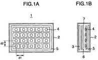
- FIGS. 1A and 1Bare schematic diagrams showing the structure of a liquid crystal display apparatus.
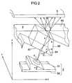
- FIG. 2is a schematic perspective view showing conceptually a backlight apparatus according to an embodiment of the present invention.
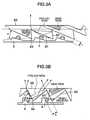
- FIGS. 3A and 3Bare partial cross sectional views of the backlight apparatus of the present invention.
- FIGS. 1A and 1Bare schematic diagrams showing the structure of a liquid crystal display apparatus.
- a liquid crystal display 3Disposed in a housing 2 of the liquid crystal display apparatus 1 are the liquid crystal display 3 for displaying information, a plurality of LED light sources (hereinafter simply called “LED's”) 4 on the back surface of the liquid crystal display 3 , and a substrate 5 on which LED's 4 are disposed in a vertical/horizontal matrix shape.
- LED'sLED light sources
- the optical guide member 6is disposed which illuminates the liquid crystal display 3 at high luminance by changing the point light sources of LED's to an area light source.
- a diffusion member 7 of a plate or sheetis further provided which illuminates the liquid crystal display 3 uniformly with light emitted from the optical guide member 6 .
- a part or whole of the diffusion member 7may be formed integrally with the optical guide member 6 .
- FIG. 2is a perspective view conceptually showing the structure of the backlight apparatus according to the embodiment of the present invention.
- FIGS. 3A and 3Bare partial cross sectional views of the backlight apparatus of the present invention.
- the constituent componentsare shown such that each is separated in a Z direction for easier understanding.
- a part of the backlight apparatusis drawn by using representative components in FIG. 2 and FIGS.
- the plurality of LED's 4 and optical guide member 6are integrally disposed in the matrix shape in a vertical/horizontal (X, Y) plane as explained above.
- Pitches (d 1 , d 2 ) of LED's 4 disposed in the matrix shapeare determined depending on a light amount of LED's 4 and an optical guide performance of the optical guide member 6 . Namely, it is set in such a manner that one LED 4 can illuminate a predetermined area of the liquid crystal display 3 at a desired luminance.
- the surface area of the substrate 5 mounting the plurality of LED's 4 , a projection area of the optical guide member 6 provided for each LED 4 and a flat area of the diffusion member 6are each approximately equal to a flat display area of the liquid crystal display 3 .
- LED's 4are placed on a flat surface 51 of the substrate 5 on the side of the liquid crystal display 3 , and electrically connected for supplying current by wirings (not shown) formed on the flat surface 51 or an opposing flat surface 52 of the substrate 5 by wire bonding or the like.
- LED 4has a predetermined directivity of optical radiation.
- LED 4is placed on the substrate 5 , being slanted by a predetermined angle ( ⁇ ). Namely, LED 4 is disposed in such a manner that the optical axis direction at the highest luminance of LED 4 is set at a predetermined inclination angle ( ⁇ ) relative to the flat surface of the liquid crystal display 3 . Light radiated from LED 4 becomes incident upon the optical guide member 6 disposed facing LED 4 .
- the optical guide member 6is made of material having optical transparency such as transparent resin.
- the optical guide member 6is constituted of: a flat plane (first flat plane) 61 for receiving the radiated light from LED 4 ; an optical guide portion for transmitting incident light; a flat plane (second flat plane) 62 for reflecting the transmitted light; and a flat plane (third flat plane) 63 for outputting incident and guided light (A) and reflected and guided light (B).
- the first flat plane 61 and second flat plane 62are intersecting or connecting each other, forming the optical guide member having a triangle shape in a cross section crossing the surface of the liquid crystal display 3 , as shown in FIG. 2 , to form the optical guide member of a wedge shape to be explained later.
- the first flat plane 61 for receiving the radiated light from LED 4is disposed to form a flat plane generally perpendicular to the optical axis of the highest luminance of LED 4 , at a position as near as possible to LED 4 , in order to efficiently receive low angle radiation light of LED 4 and illuminate the liquid crystal display 3 .
- a ridge line 64(a connection line between the first flat plane 61 and second flat plane 62 on the substrate 5 side) formed by the first flat plane 61 and second flat plane 62 on the substrate 5 side is positioned more on the substrate 5 side of a plane containing a plurality of LED's 4 .
- a portion of the first flat plane 61 and second flat plane 62is arranged to exist on the plane including the plurality of LED's.
- the ridge line 64connection line
- the ridge line 64is more preferably set as near as possible to the substrate 5 or at a position contacting the substrate 5 .
- An angle between the first flat surface 61 and the second flat plane 62is at least not larger than a right angle, i.e., an acute angle ( ⁇ 90°).
- the first flat plane 61 and the second flat plane 62constitute a portion of the optical guide member indicated by two-dot lines forming a wedge shape, and form the reflection plane 62 of a predetermined size in order to guide light to a predetermined area.
- the second flat plane 62is disposed at the acute angle relative to the first flat plane 61 , i.e., a plane perpendicular to the optical axis of the highest luminance of LED 4 , so that light incident upon the first flat plane 61 is reflected at an earlier stage to illuminate the plane of the liquid crystal display 3 near at each LED 4 at high luminance.
- this embodimentadopts the side light type backlight system disposing LED's 4 on the side of the optical guide member 6 , the optical guide distance of the optical guide member 6 is reduced in order to suppress its size in the Z direction otherwise increased by slanted arrangement.
- the emission flat plane (third flat plane) 63 for the liquid crystal display 3is formed on the optical guide member 6 on the side facing the liquid crystal display 3 .
- the output lightis diffused by a diffusion pattern (not shown) formed on the third flat plane 63 or by the diffusion member provided between the liquid crystal display 3 and optical guide member 6 , to thereby uniformly illuminate the liquid crystal display 3 .
- the diffusion member 7is shown omitted in aid of understanding the behavior of output light from the third flat plane, this does not mean that the diffusion member 7 is not necessary to be used in the embodiment.
- FIGS. 3A and 3Bshow examples of the arrangement of LED's 4 and optical guide member 6 at different inclination angles of the optical axis of LED 4 relative to the plane of the liquid crystal display 3 .
- FIG. 3Ashows an example of the arrangement at a relatively small inclination angle ( ⁇ ) of the optical axis of LED 4 relative to the plane of the liquid crystal display 3 .
- This exampleensures a relatively broad area of the first flat plane 61 upon which radiated light from LED 4 becomes incident so that it is suitable for LED's having the directivity characteristics of radiation light of LED's 4 having a relatively high angle radiation tendency (i.e., an intensity of output light in the optical axis direction of LED 4 is relatively strong and the output light directivity is strong).
- FIG. 3Ashows an example of the arrangement at a relatively small inclination angle ( ⁇ ) of the optical axis of LED 4 relative to the plane of the liquid crystal display 3 .
- ⁇inclination angle
- 3Bshows an example of the arrangement at a relatively large inclination angle ( ⁇ ) of the optical axis of LED 4 relative to the plane of the liquid crystal display 3 .
- This exampleensures a relatively broad area of the second flat plane 62 for reflecting incident light upon the first flat plane 61 so that it is suitable for LED's having the directivity characteristics of radiation light of LED's 4 showing a relatively low angle radiation tendency (i.e., an intensity of output light in the optical axis direction of LED 4 is relatively weak and the output light directivity is weak).
- Both the examplesconstitute the optical guide member indicated by two-dot lines and containing the first flat plane 61 and second flat plane 62 .
- LED's 4 and the optical guide member 6are disposed slanted by the inclination angle ( ⁇ ), an optical guide length of the optical guide member can be reduced. It is therefore possible to suppress the illumination intensity of the backlight from being lowered by the optical guide member. Further, by broadening the first flat plane 61 and second flat plane 62 of the optical guide member 6 , a larger amount of high angle radiation light of LED 4 can be made incident so that a loss of the light amount of LED 4 can be suppressed and light can be used effectively. Further, since the optical guide member 6 is positioned under LED's 4 along the direction (Z) perpendicular to the plane of the liquid crystal display 3 , a dark area will not be formed at the bottom of LED 4 .
- the backlight apparatus of the embodimentcan illuminate the surface of the liquid crystal display 3 with radiation light of LED's uniformly and at high luminance.
- the optical guide member 6is structured as explained above, it is possible to shorten a distance between LED's 4 and the liquid crystal display 3 . According to the present invention, it is therefore possible to realize a thin liquid crystal display apparatus by suppressing the size along the direction perpendicular to the plane of the liquid crystal display 3 , i.e., the side along a thickness direction (Z direction) of the liquid crystal display 3 .
- the optical guide member 6can be used as an optical guide member of the side backlight type by forming recesses on the third flat plane 63 as indicated by hatched portions in FIGS. 3A and 3B . If the optical guide member 6 of the embodiment is used for a just-under type LED backlight, an optical transmission range of the optical guide member can be expanded because each optical guide portion is formed in correspondence with the arrangement of LED's 4 . Accordingly, the number of LED's 4 can be reduced and a transmission length of the optical guide member for each LED can be shortened. It is therefore possible to irradiate light from LED's 4 to the liquid crystal display at high luminance, while a cost rise is suppressed. Furthermore, since the optical guide member 6 of this embodiment has planes for reflection/output of incidence light, a complicated diffusion pattern is not necessary to be provided for each LED 4 .
- the embodimentit is possible to uniformly irradiate light from the light source (LED) to a liquid crystal display, while the liquid crystal display apparatus is made thin and the cost is suppressed. According to the embodiment, it is therefore possible to provide a liquid crystal display apparatus which realizes high luminance, thinning and low cost.
Landscapes
- Physics & Mathematics (AREA)
- Nonlinear Science (AREA)
- Mathematical Physics (AREA)
- Chemical & Material Sciences (AREA)
- Crystallography & Structural Chemistry (AREA)
- General Physics & Mathematics (AREA)
- Optics & Photonics (AREA)
- Planar Illumination Modules (AREA)
- Light Guides In General And Applications Therefor (AREA)
- Liquid Crystal (AREA)
Abstract
Description
Claims (2)
Applications Claiming Priority (2)
| Application Number | Priority Date | Filing Date | Title |
|---|---|---|---|
| JP2008-029873 | 2008-02-12 | ||
| JP2008029873AJP5011151B2 (en) | 2008-02-12 | 2008-02-12 | Liquid crystal display equipment |
Publications (2)
| Publication Number | Publication Date |
|---|---|
| US20090201668A1 US20090201668A1 (en) | 2009-08-13 |
| US7967462B2true US7967462B2 (en) | 2011-06-28 |
Family
ID=40938704
Family Applications (1)
| Application Number | Title | Priority Date | Filing Date |
|---|---|---|---|
| US12/361,849ActiveUS7967462B2 (en) | 2008-02-12 | 2009-01-29 | Backlight assembly for liquid crystal display apparatus having inclined light emmitting elements |
Country Status (3)
| Country | Link |
|---|---|
| US (1) | US7967462B2 (en) |
| JP (1) | JP5011151B2 (en) |
| CN (1) | CN101510027B (en) |
Cited By (35)
| Publication number | Priority date | Publication date | Assignee | Title |
|---|---|---|---|---|
| US20100124077A1 (en)* | 2008-11-18 | 2010-05-20 | Higuchi Yasutaka | Surface light source device, lighting device and image display device |
| USD664704S1 (en) | 2011-11-01 | 2012-07-31 | Lsi Industries, Inc. | Lighting fixture |
| US20130128190A1 (en)* | 2011-11-23 | 2013-05-23 | Shenzhen China Star Optoelectronics Technology Co., Ltd. | Backlight Module and LCD Device |
| US8749529B2 (en) | 2012-03-01 | 2014-06-10 | Microsoft Corporation | Sensor-in-pixel display system with near infrared filter |
| US8780540B2 (en) | 2012-03-02 | 2014-07-15 | Microsoft Corporation | Flexible hinge and removable attachment |
| US8850241B2 (en) | 2012-03-02 | 2014-09-30 | Microsoft Corporation | Multi-stage power adapter configured to provide low power upon initial connection of the power adapter to the host device and high power thereafter upon notification from the host device to the power adapter |
| US8873227B2 (en) | 2012-03-02 | 2014-10-28 | Microsoft Corporation | Flexible hinge support layer |
| US9019615B2 (en) | 2012-06-12 | 2015-04-28 | Microsoft Technology Licensing, Llc | Wide field-of-view virtual image projector |
| US9052414B2 (en) | 2012-02-07 | 2015-06-09 | Microsoft Technology Licensing, Llc | Virtual image device |
| US9075566B2 (en) | 2012-03-02 | 2015-07-07 | Microsoft Technoogy Licensing, LLC | Flexible hinge spine |
| US9111703B2 (en) | 2012-03-02 | 2015-08-18 | Microsoft Technology Licensing, Llc | Sensor stack venting |
| US9152173B2 (en) | 2012-10-09 | 2015-10-06 | Microsoft Technology Licensing, Llc | Transparent display device |
| US9304549B2 (en) | 2013-03-28 | 2016-04-05 | Microsoft Technology Licensing, Llc | Hinge mechanism for rotatable component attachment |
| US9317072B2 (en) | 2014-01-28 | 2016-04-19 | Microsoft Technology Licensing, Llc | Hinge mechanism with preset positions |
| US9354748B2 (en) | 2012-02-13 | 2016-05-31 | Microsoft Technology Licensing, Llc | Optical stylus interaction |
| US9355345B2 (en) | 2012-07-23 | 2016-05-31 | Microsoft Technology Licensing, Llc | Transparent tags with encoded data |
| US9360893B2 (en) | 2012-03-02 | 2016-06-07 | Microsoft Technology Licensing, Llc | Input device writing surface |
| US9426905B2 (en) | 2012-03-02 | 2016-08-23 | Microsoft Technology Licensing, Llc | Connection device for computing devices |
| US9447620B2 (en) | 2014-09-30 | 2016-09-20 | Microsoft Technology Licensing, Llc | Hinge mechanism with multiple preset positions |
| US9513748B2 (en) | 2012-12-13 | 2016-12-06 | Microsoft Technology Licensing, Llc | Combined display panel circuit |
| US9541255B2 (en) | 2014-05-28 | 2017-01-10 | Lsi Industries, Inc. | Luminaires and reflector modules |
| US9638835B2 (en) | 2013-03-05 | 2017-05-02 | Microsoft Technology Licensing, Llc | Asymmetric aberration correcting lens |
| US9752361B2 (en) | 2015-06-18 | 2017-09-05 | Microsoft Technology Licensing, Llc | Multistage hinge |
| US9824808B2 (en) | 2012-08-20 | 2017-11-21 | Microsoft Technology Licensing, Llc | Switchable magnetic lock |
| US9864415B2 (en) | 2015-06-30 | 2018-01-09 | Microsoft Technology Licensing, Llc | Multistage friction hinge |
| US9870066B2 (en) | 2012-03-02 | 2018-01-16 | Microsoft Technology Licensing, Llc | Method of manufacturing an input device |
| US10031556B2 (en) | 2012-06-08 | 2018-07-24 | Microsoft Technology Licensing, Llc | User experience adaptation |
| US10037057B2 (en) | 2016-09-22 | 2018-07-31 | Microsoft Technology Licensing, Llc | Friction hinge |
| US10120420B2 (en) | 2014-03-21 | 2018-11-06 | Microsoft Technology Licensing, Llc | Lockable display and techniques enabling use of lockable displays |
| US10156889B2 (en) | 2014-09-15 | 2018-12-18 | Microsoft Technology Licensing, Llc | Inductive peripheral retention device |
| US10324733B2 (en) | 2014-07-30 | 2019-06-18 | Microsoft Technology Licensing, Llc | Shutdown notifications |
| US10344797B2 (en) | 2016-04-05 | 2019-07-09 | Microsoft Technology Licensing, Llc | Hinge with multiple preset positions |
| US10678743B2 (en) | 2012-05-14 | 2020-06-09 | Microsoft Technology Licensing, Llc | System and method for accessory device architecture that passes via intermediate processor a descriptor when processing in a low power state |
| US10996391B2 (en) | 2017-12-12 | 2021-05-04 | Samsung Electronics Co., Ltd. | Display device |
| USRE48963E1 (en) | 2012-03-02 | 2022-03-08 | Microsoft Technology Licensing, Llc | Connection device for computing devices |
Families Citing this family (8)
| Publication number | Priority date | Publication date | Assignee | Title |
|---|---|---|---|---|
| US20120299044A1 (en)* | 2010-02-16 | 2012-11-29 | Sharp Kabushiki Kaisha | Lighting set, lighting device, and display device |
| JP5750581B2 (en)* | 2011-06-20 | 2015-07-22 | パナソニックIpマネジメント株式会社 | Light irradiation device |
| JP2014219649A (en) | 2013-04-09 | 2014-11-20 | 船井電機株式会社 | Display device |
| CN103591512B (en)* | 2013-11-15 | 2015-09-16 | 深圳市华星光电技术有限公司 | Backlight module and the liquid crystal display module with this backlight module |
| CN103925524B (en)* | 2014-04-17 | 2016-03-09 | 上海交通大学 | The energy-saving backlight module that angle of visibility is adjustable |
| CN105937141B (en)* | 2016-06-27 | 2018-11-06 | 无锡小天鹅股份有限公司 | Controls Palette for washing machine and the washing machine with it |
| CN109686244A (en)* | 2019-02-02 | 2019-04-26 | 京东方科技集团股份有限公司 | Backlight module and display panel |
| CN114811531B (en)* | 2022-04-28 | 2024-03-22 | 富盛光电(吴江)有限公司 | Backlight module and method for reducing thickness of backlight module |
Citations (12)
| Publication number | Priority date | Publication date | Assignee | Title |
|---|---|---|---|---|
| US6241358B1 (en)* | 1998-03-31 | 2001-06-05 | Nitto Jushi Kogyo Kabushiki Kaisha | Tandem lighting panel |
| US20010053072A1 (en)* | 1999-12-24 | 2001-12-20 | Takahiro Takemoto | Planar light source apparatus having simplified configuration and providing uniform and high brightness and liquid crystal display unit including the same |
| US6464367B2 (en)* | 2000-02-24 | 2002-10-15 | Sony Corporation | Surface light source system |
| US6580477B1 (en)* | 1999-08-03 | 2003-06-17 | Samsung Electronics Co., Ltd. | Liquid crystal display including at least two light guiding plates arranged in parallel |
| JP2006344409A (en) | 2005-06-07 | 2006-12-21 | Seiko Instruments Inc | Light fixture, and display device provided with the same |
| US20070030698A1 (en) | 2005-08-03 | 2007-02-08 | Citizen Electronics Co., Ltd. | Light guide plate |
| JP2007134224A (en) | 2005-11-11 | 2007-05-31 | Showa Denko Kk | Plane light source device and display device |
| US7311431B2 (en)* | 2005-04-01 | 2007-12-25 | Avago Technologies Ecbu Ip Pte Ltd | Light-emitting apparatus having a plurality of adjacent, overlapping light-guide plates |
| US7458709B2 (en)* | 2004-05-24 | 2008-12-02 | Osram Opto Semiconductors Gmbh | Method for mounting a surface lighting system and surface lighting system |
| US20090052163A1 (en)* | 2005-05-12 | 2009-02-26 | Harison Toshiba Lighting Corporation | Back light device |
| US20090290097A1 (en)* | 2008-05-23 | 2009-11-26 | Samsung Electronics Co., Ltd. | Backlight assembly and display device having the same |
| US7721672B2 (en)* | 2005-04-21 | 2010-05-25 | Nichia Corporation | Electrically illuminating indicator needle and light guiding member |
Family Cites Families (4)
| Publication number | Priority date | Publication date | Assignee | Title |
|---|---|---|---|---|
| JP2009087538A (en)* | 2006-01-20 | 2009-04-23 | Sharp Corp | Light source unit, illumination device using the same, and display device using the same |
| JP2007265689A (en)* | 2006-03-27 | 2007-10-11 | Harison Toshiba Lighting Corp | Backlight |
| JP4962884B2 (en)* | 2006-06-06 | 2012-06-27 | 三国電子有限会社 | Surface light source device, prism sheet and liquid crystal display device |
| JP2008015288A (en)* | 2006-07-07 | 2008-01-24 | Hitachi Displays Ltd | Liquid crystal display |
- 2008
- 2008-02-12JPJP2008029873Apatent/JP5011151B2/enactiveActive
- 2009
- 2009-01-29USUS12/361,849patent/US7967462B2/enactiveActive
- 2009-02-06CNCN2009100051553Apatent/CN101510027B/enactiveActive
Patent Citations (14)
| Publication number | Priority date | Publication date | Assignee | Title |
|---|---|---|---|---|
| US6241358B1 (en)* | 1998-03-31 | 2001-06-05 | Nitto Jushi Kogyo Kabushiki Kaisha | Tandem lighting panel |
| US6580477B1 (en)* | 1999-08-03 | 2003-06-17 | Samsung Electronics Co., Ltd. | Liquid crystal display including at least two light guiding plates arranged in parallel |
| US6927812B2 (en)* | 1999-08-03 | 2005-08-09 | Samsung Electronics Co., Ltd. | Liquid crystal display including at least two light guiding plates abutting each other |
| US20010053072A1 (en)* | 1999-12-24 | 2001-12-20 | Takahiro Takemoto | Planar light source apparatus having simplified configuration and providing uniform and high brightness and liquid crystal display unit including the same |
| US6464367B2 (en)* | 2000-02-24 | 2002-10-15 | Sony Corporation | Surface light source system |
| US7458709B2 (en)* | 2004-05-24 | 2008-12-02 | Osram Opto Semiconductors Gmbh | Method for mounting a surface lighting system and surface lighting system |
| US7311431B2 (en)* | 2005-04-01 | 2007-12-25 | Avago Technologies Ecbu Ip Pte Ltd | Light-emitting apparatus having a plurality of adjacent, overlapping light-guide plates |
| US7721672B2 (en)* | 2005-04-21 | 2010-05-25 | Nichia Corporation | Electrically illuminating indicator needle and light guiding member |
| US20090052163A1 (en)* | 2005-05-12 | 2009-02-26 | Harison Toshiba Lighting Corporation | Back light device |
| JP2006344409A (en) | 2005-06-07 | 2006-12-21 | Seiko Instruments Inc | Light fixture, and display device provided with the same |
| JP2007042404A (en) | 2005-08-03 | 2007-02-15 | Citizen Electronics Co Ltd | Light guide plate |
| US20070030698A1 (en) | 2005-08-03 | 2007-02-08 | Citizen Electronics Co., Ltd. | Light guide plate |
| JP2007134224A (en) | 2005-11-11 | 2007-05-31 | Showa Denko Kk | Plane light source device and display device |
| US20090290097A1 (en)* | 2008-05-23 | 2009-11-26 | Samsung Electronics Co., Ltd. | Backlight assembly and display device having the same |
Non-Patent Citations (1)
| Title |
|---|
| English Translation of Claims and Detailed Description of Japanese Publication JP 2007-134224.* |
Cited By (66)
| Publication number | Priority date | Publication date | Assignee | Title |
|---|---|---|---|---|
| US8092066B2 (en)* | 2008-11-18 | 2012-01-10 | Enplas Corporation | Surface light source device, lighting device and image display device |
| US20100124077A1 (en)* | 2008-11-18 | 2010-05-20 | Higuchi Yasutaka | Surface light source device, lighting device and image display device |
| USD664704S1 (en) | 2011-11-01 | 2012-07-31 | Lsi Industries, Inc. | Lighting fixture |
| US9234649B2 (en) | 2011-11-01 | 2016-01-12 | Lsi Industries, Inc. | Luminaires and lighting structures |
| US9007547B2 (en)* | 2011-11-23 | 2015-04-14 | Shenzhen China Star Optoelectronics Technology Co., Ltd. | Backlight module and LCD device |
| US20130128190A1 (en)* | 2011-11-23 | 2013-05-23 | Shenzhen China Star Optoelectronics Technology Co., Ltd. | Backlight Module and LCD Device |
| US9052414B2 (en) | 2012-02-07 | 2015-06-09 | Microsoft Technology Licensing, Llc | Virtual image device |
| US9354748B2 (en) | 2012-02-13 | 2016-05-31 | Microsoft Technology Licensing, Llc | Optical stylus interaction |
| US8749529B2 (en) | 2012-03-01 | 2014-06-10 | Microsoft Corporation | Sensor-in-pixel display system with near infrared filter |
| US9426905B2 (en) | 2012-03-02 | 2016-08-23 | Microsoft Technology Licensing, Llc | Connection device for computing devices |
| US10013030B2 (en) | 2012-03-02 | 2018-07-03 | Microsoft Technology Licensing, Llc | Multiple position input device cover |
| US8873227B2 (en) | 2012-03-02 | 2014-10-28 | Microsoft Corporation | Flexible hinge support layer |
| US8903517B2 (en) | 2012-03-02 | 2014-12-02 | Microsoft Corporation | Computer device and an apparatus having sensors configured for measuring spatial information indicative of a position of the computing devices |
| US8947864B2 (en) | 2012-03-02 | 2015-02-03 | Microsoft Corporation | Flexible hinge and removable attachment |
| US8850241B2 (en) | 2012-03-02 | 2014-09-30 | Microsoft Corporation | Multi-stage power adapter configured to provide low power upon initial connection of the power adapter to the host device and high power thereafter upon notification from the host device to the power adapter |
| USRE48963E1 (en) | 2012-03-02 | 2022-03-08 | Microsoft Technology Licensing, Llc | Connection device for computing devices |
| US8830668B2 (en) | 2012-03-02 | 2014-09-09 | Microsoft Corporation | Flexible hinge and removable attachment |
| US9075566B2 (en) | 2012-03-02 | 2015-07-07 | Microsoft Technoogy Licensing, LLC | Flexible hinge spine |
| US9111703B2 (en) | 2012-03-02 | 2015-08-18 | Microsoft Technology Licensing, Llc | Sensor stack venting |
| US9134808B2 (en) | 2012-03-02 | 2015-09-15 | Microsoft Technology Licensing, Llc | Device kickstand |
| US9134807B2 (en) | 2012-03-02 | 2015-09-15 | Microsoft Technology Licensing, Llc | Pressure sensitive key normalization |
| US10963087B2 (en) | 2012-03-02 | 2021-03-30 | Microsoft Technology Licensing, Llc | Pressure sensitive keys |
| US9158384B2 (en) | 2012-03-02 | 2015-10-13 | Microsoft Technology Licensing, Llc | Flexible hinge protrusion attachment |
| US9176900B2 (en) | 2012-03-02 | 2015-11-03 | Microsoft Technology Licensing, Llc | Flexible hinge and removable attachment |
| US9176901B2 (en) | 2012-03-02 | 2015-11-03 | Microsoft Technology Licensing, Llc | Flux fountain |
| US8791382B2 (en) | 2012-03-02 | 2014-07-29 | Microsoft Corporation | Input device securing techniques |
| US9268373B2 (en) | 2012-03-02 | 2016-02-23 | Microsoft Technology Licensing, Llc | Flexible hinge spine |
| US9304949B2 (en) | 2012-03-02 | 2016-04-05 | Microsoft Technology Licensing, Llc | Sensing user input at display area edge |
| US8854799B2 (en) | 2012-03-02 | 2014-10-07 | Microsoft Corporation | Flux fountain |
| US9904327B2 (en) | 2012-03-02 | 2018-02-27 | Microsoft Technology Licensing, Llc | Flexible hinge and removable attachment |
| US8780541B2 (en) | 2012-03-02 | 2014-07-15 | Microsoft Corporation | Flexible hinge and removable attachment |
| US9870066B2 (en) | 2012-03-02 | 2018-01-16 | Microsoft Technology Licensing, Llc | Method of manufacturing an input device |
| US9360893B2 (en) | 2012-03-02 | 2016-06-07 | Microsoft Technology Licensing, Llc | Input device writing surface |
| US8780540B2 (en) | 2012-03-02 | 2014-07-15 | Microsoft Corporation | Flexible hinge and removable attachment |
| US9852855B2 (en) | 2012-03-02 | 2017-12-26 | Microsoft Technology Licensing, Llc | Pressure sensitive key normalization |
| US9460029B2 (en) | 2012-03-02 | 2016-10-04 | Microsoft Technology Licensing, Llc | Pressure sensitive keys |
| US9465412B2 (en) | 2012-03-02 | 2016-10-11 | Microsoft Technology Licensing, Llc | Input device layers and nesting |
| US9793073B2 (en) | 2012-03-02 | 2017-10-17 | Microsoft Technology Licensing, Llc | Backlighting a fabric enclosure of a flexible cover |
| US9766663B2 (en) | 2012-03-02 | 2017-09-19 | Microsoft Technology Licensing, Llc | Hinge for component attachment |
| US9618977B2 (en) | 2012-03-02 | 2017-04-11 | Microsoft Technology Licensing, Llc | Input device securing techniques |
| US9619071B2 (en) | 2012-03-02 | 2017-04-11 | Microsoft Technology Licensing, Llc | Computing device and an apparatus having sensors configured for measuring spatial information indicative of a position of the computing devices |
| US9710093B2 (en) | 2012-03-02 | 2017-07-18 | Microsoft Technology Licensing, Llc | Pressure sensitive key normalization |
| US9678542B2 (en) | 2012-03-02 | 2017-06-13 | Microsoft Technology Licensing, Llc | Multiple position input device cover |
| US10678743B2 (en) | 2012-05-14 | 2020-06-09 | Microsoft Technology Licensing, Llc | System and method for accessory device architecture that passes via intermediate processor a descriptor when processing in a low power state |
| US10031556B2 (en) | 2012-06-08 | 2018-07-24 | Microsoft Technology Licensing, Llc | User experience adaptation |
| US9019615B2 (en) | 2012-06-12 | 2015-04-28 | Microsoft Technology Licensing, Llc | Wide field-of-view virtual image projector |
| US10107994B2 (en) | 2012-06-12 | 2018-10-23 | Microsoft Technology Licensing, Llc | Wide field-of-view virtual image projector |
| US9355345B2 (en) | 2012-07-23 | 2016-05-31 | Microsoft Technology Licensing, Llc | Transparent tags with encoded data |
| US9824808B2 (en) | 2012-08-20 | 2017-11-21 | Microsoft Technology Licensing, Llc | Switchable magnetic lock |
| US9152173B2 (en) | 2012-10-09 | 2015-10-06 | Microsoft Technology Licensing, Llc | Transparent display device |
| US9513748B2 (en) | 2012-12-13 | 2016-12-06 | Microsoft Technology Licensing, Llc | Combined display panel circuit |
| US9638835B2 (en) | 2013-03-05 | 2017-05-02 | Microsoft Technology Licensing, Llc | Asymmetric aberration correcting lens |
| US9304549B2 (en) | 2013-03-28 | 2016-04-05 | Microsoft Technology Licensing, Llc | Hinge mechanism for rotatable component attachment |
| US9317072B2 (en) | 2014-01-28 | 2016-04-19 | Microsoft Technology Licensing, Llc | Hinge mechanism with preset positions |
| US10120420B2 (en) | 2014-03-21 | 2018-11-06 | Microsoft Technology Licensing, Llc | Lockable display and techniques enabling use of lockable displays |
| US9541255B2 (en) | 2014-05-28 | 2017-01-10 | Lsi Industries, Inc. | Luminaires and reflector modules |
| US10324733B2 (en) | 2014-07-30 | 2019-06-18 | Microsoft Technology Licensing, Llc | Shutdown notifications |
| US10156889B2 (en) | 2014-09-15 | 2018-12-18 | Microsoft Technology Licensing, Llc | Inductive peripheral retention device |
| US9964998B2 (en) | 2014-09-30 | 2018-05-08 | Microsoft Technology Licensing, Llc | Hinge mechanism with multiple preset positions |
| US9447620B2 (en) | 2014-09-30 | 2016-09-20 | Microsoft Technology Licensing, Llc | Hinge mechanism with multiple preset positions |
| US9752361B2 (en) | 2015-06-18 | 2017-09-05 | Microsoft Technology Licensing, Llc | Multistage hinge |
| US10606322B2 (en) | 2015-06-30 | 2020-03-31 | Microsoft Technology Licensing, Llc | Multistage friction hinge |
| US9864415B2 (en) | 2015-06-30 | 2018-01-09 | Microsoft Technology Licensing, Llc | Multistage friction hinge |
| US10344797B2 (en) | 2016-04-05 | 2019-07-09 | Microsoft Technology Licensing, Llc | Hinge with multiple preset positions |
| US10037057B2 (en) | 2016-09-22 | 2018-07-31 | Microsoft Technology Licensing, Llc | Friction hinge |
| US10996391B2 (en) | 2017-12-12 | 2021-05-04 | Samsung Electronics Co., Ltd. | Display device |
Also Published As
| Publication number | Publication date |
|---|---|
| CN101510027B (en) | 2012-03-14 |
| JP2009193669A (en) | 2009-08-27 |
| CN101510027A (en) | 2009-08-19 |
| US20090201668A1 (en) | 2009-08-13 |
| JP5011151B2 (en) | 2012-08-29 |
Similar Documents
| Publication | Publication Date | Title |
|---|---|---|
| US7967462B2 (en) | Backlight assembly for liquid crystal display apparatus having inclined light emmitting elements | |
| US11112650B2 (en) | Backlight module and display device | |
| JP3379043B2 (en) | Planar lighting device | |
| JP5241068B2 (en) | Side light emitting device, backlight unit using the same as light source, and liquid crystal display device using the same | |
| KR101167301B1 (en) | Back light unit of liquid crystal display device | |
| JP4902566B2 (en) | Surface illumination device and display device | |
| US8684588B2 (en) | Light guide elements for display device | |
| US20080007673A1 (en) | Liquid crystal display device | |
| US7794100B2 (en) | Planar light source apparatus, display apparatus and planar illumination method | |
| JPWO2009098809A1 (en) | Illumination device and liquid crystal display device | |
| JP2006148036A (en) | Light emitting light source and light emitting light source array | |
| US7543965B2 (en) | Side light-emitting device, backlight unit having the side light-emitting device, and liquid crystal display apparatus employing the backlight unit | |
| US8659721B2 (en) | Liquid crystal display device having reflecting surface in zigzag manner with polygonal line | |
| MX2011003302A (en) | Light source device and illumination device using the same. | |
| CN111025743A (en) | Light source module and display device | |
| JP5386551B2 (en) | Light emitting device, display device, and reflecting member design method | |
| US20090066878A1 (en) | Liquid Crystal Display Apparatus | |
| US11143910B2 (en) | Lighting device and display device | |
| WO2018199011A1 (en) | Backlight | |
| US10718973B2 (en) | Display device | |
| CN217544055U (en) | Backlight module and display device | |
| JP2005150037A (en) | Planar lighting device and display using it | |
| CN219016749U (en) | Backlight module and display device | |
| CN220020054U (en) | Backlight display module, head-up display device and automobile | |
| JP4517307B2 (en) | Surface light source device and image display device |
Legal Events
| Date | Code | Title | Description |
|---|---|---|---|
| AS | Assignment | Owner name:HITACHI, LTD., JAPAN Free format text:ASSIGNMENT OF ASSIGNORS INTEREST;ASSIGNORS:OGIRO, KENJI;MASUOKA, NOBUO;FUJITA, KOUJI;REEL/FRAME:022173/0972;SIGNING DATES FROM 20090113 TO 20090114 | |
| STCF | Information on status: patent grant | Free format text:PATENTED CASE | |
| FEPP | Fee payment procedure | Free format text:PAYOR NUMBER ASSIGNED (ORIGINAL EVENT CODE: ASPN); ENTITY STATUS OF PATENT OWNER: LARGE ENTITY | |
| AS | Assignment | Owner name:HITACHI CONSUMER ELECTRONICS CO., LTD., JAPAN Free format text:ASSIGNMENT OF ASSIGNORS INTEREST;ASSIGNOR:HITACHI, LTD.;REEL/FRAME:030648/0217 Effective date:20130607 | |
| AS | Assignment | Owner name:HITACHI MAXELL, LTD., JAPAN Free format text:ASSIGNMENT OF ASSIGNORS INTEREST;ASSIGNORS:HITACHI CONSUMER ELECTRONICS CO., LTD.;HITACHI CONSUMER ELECTRONICS CO, LTD.;REEL/FRAME:033694/0745 Effective date:20140826 | |
| FPAY | Fee payment | Year of fee payment:4 | |
| AS | Assignment | Owner name:MAXELL, LTD., JAPAN Free format text:ASSIGNMENT OF ASSIGNORS INTEREST;ASSIGNOR:HITACHI MAXELL, LTD.;REEL/FRAME:045142/0208 Effective date:20171001 | |
| MAFP | Maintenance fee payment | Free format text:PAYMENT OF MAINTENANCE FEE, 8TH YEAR, LARGE ENTITY (ORIGINAL EVENT CODE: M1552); ENTITY STATUS OF PATENT OWNER: LARGE ENTITY Year of fee payment:8 | |
| AS | Assignment | Owner name:MAXELL HOLDINGS, LTD., JAPAN Free format text:MERGER;ASSIGNOR:MAXELL, LTD.;REEL/FRAME:058255/0579 Effective date:20211001 | |
| AS | Assignment | Owner name:MAXELL, LTD., JAPAN Free format text:CHANGE OF NAME;ASSIGNOR:MAXELL HOLDINGS, LTD.;REEL/FRAME:058666/0407 Effective date:20211001 | |
| MAFP | Maintenance fee payment | Free format text:PAYMENT OF MAINTENANCE FEE, 12TH YEAR, LARGE ENTITY (ORIGINAL EVENT CODE: M1553); ENTITY STATUS OF PATENT OWNER: LARGE ENTITY Year of fee payment:12 |