US7966388B1 - Network management system and graphical user interface - Google Patents
Network management system and graphical user interfaceDownload PDFInfo
- Publication number
- US7966388B1 US7966388B1US09/469,206US46920699AUS7966388B1US 7966388 B1US7966388 B1US 7966388B1US 46920699 AUS46920699 AUS 46920699AUS 7966388 B1US7966388 B1US 7966388B1
- Authority
- US
- United States
- Prior art keywords
- network
- user
- connection
- bandwidth
- switch
- Prior art date
- Legal status (The legal status is an assumption and is not a legal conclusion. Google has not performed a legal analysis and makes no representation as to the accuracy of the status listed.)
- Expired - Fee Related, expires
Links
- 238000000034methodMethods0.000claimsdescription78
- 230000004044responseEffects0.000claimsdescription11
- 238000003860storageMethods0.000claimsdescription6
- 238000010586diagramMethods0.000description31
- 238000004891communicationMethods0.000description29
- 230000008569processEffects0.000description14
- 238000004458analytical methodMethods0.000description9
- 238000013461designMethods0.000description6
- 239000003054catalystSubstances0.000description5
- 230000008859changeEffects0.000description5
- 239000003795chemical substances by applicationSubstances0.000description5
- 238000012217deletionMethods0.000description5
- 230000037430deletionEffects0.000description5
- 230000008901benefitEffects0.000description4
- 101150012579ADSL geneProteins0.000description3
- 102100020775Adenylosuccinate lyaseHuman genes0.000description3
- 108700040193Adenylosuccinate lyasesProteins0.000description3
- 102100031184C-Maf-inducing proteinHuman genes0.000description3
- 101000993081Homo sapiens C-Maf-inducing proteinProteins0.000description3
- 206010047289Ventricular extrasystolesDiseases0.000description3
- 230000004913activationEffects0.000description3
- 230000003044adaptive effectEffects0.000description3
- 238000012360testing methodMethods0.000description3
- 238000013459approachMethods0.000description2
- 238000011161developmentMethods0.000description2
- 230000018109developmental processEffects0.000description2
- 230000000977initiatory effectEffects0.000description2
- 230000007246mechanismEffects0.000description2
- 230000002085persistent effectEffects0.000description2
- 238000003825pressingMethods0.000description2
- 230000001360synchronised effectEffects0.000description2
- 238000013519translationMethods0.000description2
- ODKSFYDXXFIFQN-BYPYZUCNSA-NL-arginineChemical compoundOC(=O)[C@@H](N)CCCN=C(N)NODKSFYDXXFIFQN-BYPYZUCNSA-N0.000description1
- 230000002776aggregationEffects0.000description1
- 238000004220aggregationMethods0.000description1
- 238000005538encapsulationMethods0.000description1
- 238000005516engineering processMethods0.000description1
- 238000009434installationMethods0.000description1
- 238000004519manufacturing processMethods0.000description1
- 239000000463materialSubstances0.000description1
- 238000012545processingMethods0.000description1
- 230000033772system developmentEffects0.000description1
- 230000026676system processEffects0.000description1
- 238000012546transferMethods0.000description1
- 230000007723transport mechanismEffects0.000description1
Images


Classifications
- H—ELECTRICITY
- H04—ELECTRIC COMMUNICATION TECHNIQUE
- H04L—TRANSMISSION OF DIGITAL INFORMATION, e.g. TELEGRAPHIC COMMUNICATION
- H04L45/00—Routing or path finding of packets in data switching networks
- H—ELECTRICITY
- H04—ELECTRIC COMMUNICATION TECHNIQUE
- H04L—TRANSMISSION OF DIGITAL INFORMATION, e.g. TELEGRAPHIC COMMUNICATION
- H04L41/00—Arrangements for maintenance, administration or management of data switching networks, e.g. of packet switching networks
- H—ELECTRICITY
- H04—ELECTRIC COMMUNICATION TECHNIQUE
- H04L—TRANSMISSION OF DIGITAL INFORMATION, e.g. TELEGRAPHIC COMMUNICATION
- H04L41/00—Arrangements for maintenance, administration or management of data switching networks, e.g. of packet switching networks
- H04L41/04—Network management architectures or arrangements
- H04L41/052—Network management architectures or arrangements using standardised network management architectures, e.g. telecommunication management network [TMN] or unified network management architecture [UNMA]
- H—ELECTRICITY
- H04—ELECTRIC COMMUNICATION TECHNIQUE
- H04L—TRANSMISSION OF DIGITAL INFORMATION, e.g. TELEGRAPHIC COMMUNICATION
- H04L41/00—Arrangements for maintenance, administration or management of data switching networks, e.g. of packet switching networks
- H04L41/08—Configuration management of networks or network elements
- H04L41/0803—Configuration setting
- H04L41/0806—Configuration setting for initial configuration or provisioning, e.g. plug-and-play
- H—ELECTRICITY
- H04—ELECTRIC COMMUNICATION TECHNIQUE
- H04L—TRANSMISSION OF DIGITAL INFORMATION, e.g. TELEGRAPHIC COMMUNICATION
- H04L41/00—Arrangements for maintenance, administration or management of data switching networks, e.g. of packet switching networks
- H04L41/22—Arrangements for maintenance, administration or management of data switching networks, e.g. of packet switching networks comprising specially adapted graphical user interfaces [GUI]
- H—ELECTRICITY
- H04—ELECTRIC COMMUNICATION TECHNIQUE
- H04L—TRANSMISSION OF DIGITAL INFORMATION, e.g. TELEGRAPHIC COMMUNICATION
- H04L45/00—Routing or path finding of packets in data switching networks
- H04L45/42—Centralised routing
- H—ELECTRICITY
- H04—ELECTRIC COMMUNICATION TECHNIQUE
- H04L—TRANSMISSION OF DIGITAL INFORMATION, e.g. TELEGRAPHIC COMMUNICATION
- H04L41/00—Arrangements for maintenance, administration or management of data switching networks, e.g. of packet switching networks
- H04L41/50—Network service management, e.g. ensuring proper service fulfilment according to agreements
- H04L41/5003—Managing SLA; Interaction between SLA and QoS
- H—ELECTRICITY
- H04—ELECTRIC COMMUNICATION TECHNIQUE
- H04L—TRANSMISSION OF DIGITAL INFORMATION, e.g. TELEGRAPHIC COMMUNICATION
- H04L41/00—Arrangements for maintenance, administration or management of data switching networks, e.g. of packet switching networks
- H04L41/50—Network service management, e.g. ensuring proper service fulfilment according to agreements
- H04L41/5041—Network service management, e.g. ensuring proper service fulfilment according to agreements characterised by the time relationship between creation and deployment of a service
- H04L41/5054—Automatic deployment of services triggered by the service manager, e.g. service implementation by automatic configuration of network components
Definitions
- the present inventionrelates to a network management system for configuring a network connection between first and second service access points, to user interfaces for network management systems, and to online network management applications.
- Existing network architecturesfor a single network provider, include a plurality of subnetworks or subnets.
- each subnetworkis made up of network hardware in accordance with a specific vendor hardware platform used in that subnetwork. Because the provider has a plurality of subnetworks, the various subnetworks are interconnected with each other, connecting the network hardware components from various different hardware platforms to each other. When network hardware from various different hardware platforms is connected together, configuration is rather difficult.
- Each hardware platformtypically has its own interface that is used to configure that type of hardware.
- a first element manageris used to interface with network hardware in a first hardware platform of one subnet
- a different element mangeris used to interface with another subnet that uses a different hardware platform.
- itis necessary to individually, tediously, configure each subnet to subnet interface on each side with the appropriate configuration tool.
- configurationcan take considerable time, and be quite difficult.
- an object of the present inventionto provide a network management system for configuring a network connection between first and second service access points that utilizes an information manager and a configuration manager to utilize a generic set of models so that nodal processors and other network hardware from different manufacturers can be inserted into the network with minimal changes to the software which controls the devices.
- a network management systemfor configuring a network connection between a first service access point and the second service access point over a network.
- the networkincludes a plurality of subnets. Each subnet has a corresponding element type and includes at least one programmable element of that type. Each element type has a corresponding element manager.
- the systemcomprises an information manager and a configuration manager.
- the information managerincludes routing information for the network.
- the information manageris operative to determine a route made up of links over the network from the first point to the second point.
- a network-to-network linkconnects a pair of adjacent subnets having elements of different types.
- a network logical linkprovides a path across a subnet.
- the configuration manageroperates to establish a connection across each subnet on the route by sending a request to the corresponding element manager to program the at least one subnet element.
- the elementis programmed in accordance with the network logical link across that subnet.
- the configuration managerfurther operates to establish a network-to-network connection between adjacent subnets on the route in accordance with the network-to-network link between those adjacent subnets to provide the network connection between the first point and the second point.
- the route determined by the information manageris in the form of a link list.
- the link listmay be represented by a user logical link composed of a series of network logical links connected by network-to-network links, the series beginning with an originating link and ending with a terminating link.
- the information managerfurther operates to determine the path for each network logical link.
- Each pathincludes a series of elements wherein a cross connection provides a path across an element and a physical link connects a pair of adjacent elements.
- the configuration managerestablishes a connection in accordance with the path for each subnet.
- the systemfurther comprises a user interface configured to allow a user to utilize the information manager and the configuration manager to establish a network connection.
- the user interfaceis a graphical user interface (GUI), in a browser executable format such as JAVA.
- GUIgraphical user interface
- other formatsmay be used such as ACTIVE X.
- a computer readable storage mediumhaving instruction stored thereon.
- the computer readable storage mediumcomprises instructions for determining a route made up of links over the network from the first point to the second point.
- a network to network linkconnects a pair of adjacent subnets having elements of different types, and a network logical link provides a path across a subnet.
- the mediumfurther comprises instructions for establishing a connection across each subnet on the route by sending a request to the corresponding element manager to program the at least one subnet element.
- a network to network connectionis established with adjacent subnets, in accordance with the network to network link between the adjacent subnets to provide the network connection between the first point and the second point.
- a computer readable storage mediumhaving instructions stored thereon.
- the instructionsare executable by a computer to provide a graphical user interface to a network management system for configuring a network connection between a first service access point and a second service access point over a network including a plurality of subnets.
- Each subnethas a corresponding element type and includes at least one programmable element of that type.
- Each element typehas a corresponding element manager.
- the mediumfurther comprises instructions for providing a graphical user interface.
- the graphical interfaceincludes at least one interface screen displaying information that directs a system user to select the first and second service access points. Further, displayed information directs, that is, provides the option to, the system user to initiate a connection build.
- the mediumfurther comprises instructions for initiating the connection build by sending a message to the network management system.
- the messageincludes information such that in response to receiving the message, the network management system determines a route made up of links over the network from the first point to the second point.
- a network to network linkconnects a pair of adjacent subnets having elements of different types.
- a network logical linkprovides a path across a subnet.
- the network management systemestablishes a connection across each subnet on the route by sending a request to the corresponding element managers to program the at least one subnet element in accordance with the network logical link across that subnet. Further, the network management system establishes a network to network connection between adjacent subnets on the route in accordance with the network to network link between those adjacent subnets to provide the network connection between the first point and the second point.
- the instructions for providing a graphical interfacefurther comprise instructions for displaying information that directs the system user to terminate the network connection, and instructions for terminating the network connection.
- the network connectionis terminated by sending a message to the network management system.
- the messageincludes information such that in response to receiving the message, the network management system terminates the network connection.
- the mediumfurther comprises instructions for establishing a connection between the graphical user interface and the network management system. In some embodiments, the medium further comprises instructions for terminating a connection between the graphical user interface and the network management system. In some embodiments, at least some of the instructions are in a browser executable format such as, for example, JAVA or ACTIVE X. In some embodiments, at least some of the instructions are in a format that is executable on a virtual machine. Further, in some embodiments, the medium further comprises instructions for operating a non-graphical background process for handing communication with the network management system such as, for example, a UNIX daemon.
- the instructions for providing the graphical user interfacefurther comprise instructions for displaying a menubar having a button that, when pressed, causes the at least one interface screen to be displayed. In some embodiments, the instructions for providing the graphical user interface further comprise instructions for displaying a menubar having an expansion arrow/button that, when pressed, causes the at least one interface screen to be displayed. In some embodiments, the instructions for providing the graphical user interface further comprise instructions for displaying the at least one interface screen, wherein the at least one interface screen includes an introduction screen having a plurality of buttons corresponding to introduction documentation. Further, in some embodiments, the at least one interface screen includes a provision screen that directs the system user to select the first and second service access points. Further, in some embodiments, the at least one interface screen includes at least one topology screen that illustrates the route over the network between the first and second access points.
- the at least one topology screenmay include one or more of the following: a screen illustrating the route at a service management layer, a screen illustrating the route at a network management layer, a screen illustrating the route at a network element layer, and a screen illustrating the route at a network element layer including element provisioning information.
- topology screens at different layersare nested together such that the user may navigate through the different screens by clicking different parts of each layer with the mouse, or in any other suitable fashion.
- a preferred embodimentincludes instructions for displaying a plurality of tab views such that selection of a tab by the user brings the associated view within sight of the user.
- a screencould contain a plurality of tabs including: introduction, provision, topology, utility, help, and about. Selecting one of the tabs would bring that tab to the front, within sight of the user.
- the topology tabfor example, would initially show the service management layer, while allowing the user to advance through the topology to the lower levels such as the network management layer and network element layer.
- the graphical user interfaceprovides, for the very first time, a graphical display allowing the system user to manager and configure information of the network in a convenient matter.
- the networkis made up of components from various vendors, while the graphical interface is independent of whatever varying hardware components are located in the physical network.
- the management systemcommunicates with the GUI and with the various element managers.
- a computer readable storage mediumhas instructions stored thereon that are executable by a computer to provide, to a user, a user interface to a network management system for configuring a network connection between a provider access point and a user access point over a network including a permanent virtual circuit (PVC) between a switch and the user access point.
- the mediumfurther comprises instructions for providing a user interface that directs the user to select a connection bandwidth for the virtual circuit, instructions for receiving, through the user interface, a message indicative of a selected bandwidth from the user, and instructions for remotely provisioning the switch.
- the switchis provisioned with the network management system in response to receiving the message, and is provisioned to throttle the network connection at the switch such that the connection bandwidth between the switch and the user access point is limited by the selected bandwidth.
- the user interfaceis a graphical user interface, and user authentication is used prior to provisioning the switch.
- the mediumfurther comprises instructions for directing the user to select the time duration for the selected connection bandwidth and, thereafter, throttling the network connection at the switch to the selected bandwidth for the selected time duration, and thereafter, throttling the PVC to the previous bandwidth.
- a methodfor remotely provisioning the switch to throttle the permanent virtual circuit (PVC) in response to a message indicating a bandwidth selected by the user during a user session at a graphical user interface.
- remotely provisioning the switch with the network management systemprovides bandwidth on-demand for the user.
- embodiments of the present inventionprovide a generic set of models so that nodal processors and other network hardware from different manufacturers can be inserted into the network with minimal changes to the software which controls (for example, provisioning, performance, fault) the device.
- embodiments of the present inventionprovide an umbrella management system that cooperates with the service access and network layers to utilize an information manager and a configuration manager to establish the network connection using logical links that are independent of the particular hardware at the element level, in addition to providing a novel graphical user interface.
- FIG. 1is a diagram of the Umbrella Management System (UMS) in a preferred embodiment of the present invention
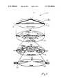
- FIG. 2shows the functional/informational architecture of the UMS
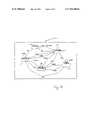
- FIG. 3is a schematic illustration of an xDSL Path in a DSL implementation
- FIG. 4shows a linked-list topology for a network logical link
- FIG. 5shows a class diagram for the UMS
- FIG. 6shows a thread diagram for the UMS
- FIG. 7illustrates the topology of the UMS
- FIG. 8shows the inheritance and association diagram for the UMS
- FIG. 9shows the state machine for the Catalyst 5000 configuration in a prototype UMS
- FIG. 10shows the state machine for the Cisco 7200 configuration in a prototype UMS
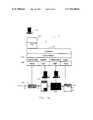
- FIG. 11shows the UMS functional architecture
- FIG. 12depicts the communications design of the UMS in a prototype
- FIG. 13shows an initialize object diagram
- FIG. 14shows an initialize message diagram
- FIG. 15shows a path trace object diagram
- FIG. 16shows a provision object diagram
- FIG. 17shows a provision message diagram
- FIG. 18shows a topology object diagram
- FIG. 19shows a topology message diagram
- FIG. 20is a screen display depicting a common desktop environment (CDE) menubar of a graphical user interface (GUI) for the Umbrella Management System (UMS);
- CDEcommon desktop environment
- GUIgraphical user interface
- UMSUmbrella Management System
- FIG. 21is a screen display depicting an application subpanel that is accessible through the menubar of FIG. 20 ;
- FIG. 22is a screen display depicting a provisioning tool, with the introduction tab in front, that is used to interface with the Umbrella Management System (UMS);
- UMSUmbrella Management System
- FIG. 23is a screen display depicting the provisioning tool, with the provision tab in front, illustrating the selection of A and Z end points;
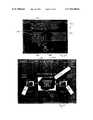
- FIG. 24is a screen display depicting the provisioning tool, with the topology tab in front, illustrating the Service Management Layer view of the A to Z connection;
- FIG. 25is a screen display depicting the Network Management Layer (NML) for the prototype implementation
- FIG. 26is a screen display depicting the cross connects and physical links for a subnet shown in FIG. 25 ;
- FIG. 27is a screen display depicting the provisioning information for a cross connect
- FIG. 28is a screen display depicting shutting down the provisioning tool
- FIG. 29is another system block diagram, illustrating a user communicating with the UMS to perform, for example, remote provisioning possibly including bandwidth on demand;
- FIG. 30is a block diagram illustrating yet another method of the present invention.
- FIG. 31is a block diagram illustrating additional steps in a preferred method.
- the network management system of the present inventionallows for rapid service activation and turn-up of digital subscriber line (xDSL) services including asynchronous transfer mode (ATM) port and xDSL line assignments.
- xDSLdigital subscriber line
- ATMsynchronous transfer mode
- TTNTelecommunications Management Network
- the present inventionwas developed to minimize system development time and cost should architectures or hardware components form any potential supplier be required to change in the network, for example, the U S West Network.
- Flexible software of the present inventionallows for rapidly scaling the system to accommodate processing large numbers of xDSL spoke subscribers and ATM hub service orders (in a hub and spoke network).
- the key attributes of the method and softwareallow for autotranslations to the ATM switch platform and xDSL digital subscriber line access multiplexors (DSLAMs) to be done on-the-fly in virtually real time (approximately 40 seconds per translation). Normal manual processes would require much more time per order, thus saving precious service order representative time to allow for more orders per day per representative.
- the present inventionmay be adapted to other networks besides ATM/DSL networks.
- the purpose of the following descriptionis to provide the analysis and design of the UMS Prototype that the inventors have developed as an exemplary implementation for a network management system of the present invention.
- the analysisincludes the object-oriented domain analysis, presented in the form of Booch diagrams. Included in the analysis are the inheritance and aggregation diagrams.
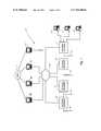
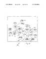
- FIG. 1illustrates the elements and the element managers, in the UMS used for the prototype.
- UMS hardwareis generally indicated at 10 with the UMS itself indicated at 12 .
- a network cloud 14illustrates the interconnection of network hardware 16 , 18 , 20 , 22 from various venders. That is, each network hardware block represents a set of network elements having a particular type, where the element types are different in the different hardware blocks. As such, as-is, each network hardware element set 16 , 18 , 20 , 22 is programmed by interfacing with an associated element manager 46 , 48 , 50 , 52 , respectively.
- UMS 12is operative to interface with the various element managers 46 , 48 , 50 , 52 , by using the information manager and the configuration manager of the UMS, to program elements in the various groups of different network hardware 16 , 18 , 20 , 22 .
- Network hardware blocks 16 , 18 , 20 , 22may also be referred to as subnets.
- UMS 12allows the provisioning of a network connection from an end user 24 , 26 , 28 to any of various interfaces 30 , 32 , 34 , 36 (which may vary in type, for example, ADSL, HDSL, Frame Relay, etc.).
- the following sectiondiscusses the analysis of the software developed for each of the four (4) element managers (for the prototype) used to control the exemplary network hardware which, includes the Catalyst 5000, Newbridge 36170, Cascade 9000, and the Cisco 7200.
- GUIgraphical user interface
- the Network Management Layer (NML) analysisincludes the Configuration Manager (NMLcm) and the Information Manager (NMLim).
- NMLcmConfiguration Manager
- NMLimInformation Manager
- a generic functional and information modelcan be instantiated into specific examples, such as a Catalyst 5500, Ascend 4004, or BANC 6000, or any other type of network hardware.
- the major goal of developing a generic set of models of the present inventionis so that different manufacturer's nodal processors and other network hardware can be inserted into the network with minimal changes to the software which controls (for example, provisioning, performance, fault) the device.
- a nodal processor or a set of nodal processorscan be used in conjunction with other network elements to provide a service.
- the information model developeddefines a functional model for providing an end-to-end service.
- a set of nodal processors in conjunction with Frame Relay, and/or ATMcould provide an Internet service provider (ISP) connection for customers.
- ISPInternet service provider
- the major goal of the inventionis to map the Frame Relay and/or ATM and/or other switches, and nodal processors and other network hardware into a vendor independent network-level topology. Once this is accomplished, a functional model allows a DSL link and DSL path to be defined.
- a DSL pathdefines an “A” endpoint and a “Z” endpoint.
- the “A” endpointcould be an ATM interface, and the “Z” endpoint a DSL interface.
- the A to Z pathis not limited to any particular interface types of the path ends. Provisioning menus presented to the user (or performed automatically based on developed rules) allow the optioning of such parameters as ATM Peak Cell Rate (PCR), Sustainable Cell Rate (SCR), and Maximum Burst Size (MBS), in an ATM/DSL implementation.
- PCRPeak Cell Rate
- SCRSustainable Cell Rate
- MBSMaximum Burst Size
- the nodal processoris architect as a device which allows many different kinds of premises LAN traffic to be transported over a variety of WAN transport mechanisms.
- the specifications and requirements of a generic nodal processorare analyzed, and object-oriented concepts, are used to model the architecture of a nodal processor.
- CM or NMLcmthe responsibility of the Configuration Manager is to take requests from the Service Management Level (SML), communicate with the Information Manager (IM or NMLim) to determine whether the request can be met, and then communicate with the individual Element Managers to request connections.
- SMLService Management Level
- IM or NMLimInformation Manager
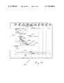
- Functional architecture generally indicated at 60includes the following layers: service session layer 62 , customer network layer 64 , carrier network layer 66 , switch or element layer 68 .
- various service access points 70 , 72 , 74are available for selection.
- first and second service access points 72 and 74are selected to provide a customer with a connection to an Internet service provider (ISP).
- ISPInternet service provider
- the route over the networkis made up of various links, crossing various subnets 76 .
- various network hardwaresuch as switches 80 provide the path across the subnet. That is, the different subnets may have different types of elements (from different hardware manufacturers).
- each switchis made up of cross connections between ports 82 of the switch. It is believed that through object-oriented techniques that an information and functional architecture can be constructed in accordance with the present invention which can support more than ATM networks.
- UAPUser Access Points
- UAPUser Access Points
- the routing function performed at the Network Management Layercan best be described in a preferred embodiment by the NMLcm transmitting a route request to the NMLim.
- the route returned by the NMLimmay be in the form of an object which potentially could be a link list which is represented by a user logical link composed of a series of network logical links connected by network-to-network links, the series beginning with an originating link and ending with a terminating link.
- the NMLcminterprets the returned route and constructs and transmits nllCreate requests with NAP (Network Access Points) as attributes to the proper element managers. That is, access points are passed to the appropriate element manager and a network logic link is requested. To allow the request to take place, a vendor independent topology engine has been developed. In addition, the ability for the NMLcm to auto discover the element managers is preferred.
- NAPNetwork Access Points
- the responsibility of the Information Manager (IM)is to maintain (create and update) the vendor independent topology of the network level view.
- the topology which must be maintainedincludes path connections as shown in FIG. 3 .
- the Path connections(for example, DSL path 102 ), which for this exemplary design are called xDSL path connections, each include a series of cross connects 112 and Virtual Circuit Links (VCLs) 110 to define a virtual circuit connection (VCC) 108 between nodal processors 104 .
- VCLsVirtual Circuit Links
- the crossconnects, by definition, connect two ports within one element and have a unique identifier.
- the VCLconnects two ports from two elements and is locally uniquely defined by an address (VPI/VCI for ATM) or VLAN or equivalent identifier.
- IMInformation Manager
- the Information Managershould be able to perform a path trace which is the identification of each cross connect, and VCL, end-to-end (in the example).
- a request from the Configuration Manager (CM)is for a route to connect two xDSL UAP (User Access Points).
- the returned information from the IM to the CMshould be a DTL (Destination Transit List) which is (for example) a linked-list as shown in FIG. 4 .
- the listincludes VLAN identifiers 122 , 124 at its ends.
- port assignments for each switchfor example, port identifiers 126 , 128
- virtual pathfor example, VPI/VCI 130
- the linked-listidentifies each cross connect and VCL for the end-to-end xDSL Path.
- Each cross connect entry in the linked-linkshould contain the following information: Equipment Identifier, Shelf Identifier, Slot Identifier, Port Identifier for both ports to which the cross connect should be made and the VPI/VCI values for both ports.
- Equipment IdentifierEquipment Identifier
- Shelf IdentifierSlot Identifier
- Port Identifierfor both ports to which the cross connect should be made
- VPI/VCI valuesfor both ports.
- embodiments of the present inventionare not limited to a particular type of network connection, and ATM over DSL (and other DSL approaches such as Frame Relay/DSL) is just an example.
- the terminology used to illustrate the exampleis exemplary terminology appropriate for the example and is not meant to be limiting.
- the user interface in an exemplary implementationmay be in a browser executable format such as JAVA.
- the aim of writing the user interface in JAVAis to enable the use of the applet from any web browser.
- the preferred user interfaceincludes two unique Thread modules.
- the first modulerecords user input and updates the graphical user interface (GUI).
- the second modulecommunicates with the Umbrella Management System (UMS) and invokes methods of the first module to update the interface display.
- UMSUmbrella Management System
- the second modulemay be a UMS daemon.
- UMSUmbrella Management System
- both the main thread and the communications threadmay be started automatically, or the two modules may be started manually.
- the communications threadopens a socket 138 to the UMS 140 for the passing of data to/from GUI 142 .
- method callsmay be sent between the GUI and the UMS ( FIG. 6 , generally indicated at 150 ).
- the Java appletpreferably provides more than just a user interface.
- the GUIprovides a topology view of the network at several different layers of abstraction. As best shown in FIG. 7 , the GUI shows the Service Management Layer 172 , the Network Management Layer 174 , and the Element Layer 176 of the UMS.
- a preferred embodiment of a graphical user interfaceis shown in greater detail in FIGS. 20-28 , described later herein, but briefly referenced immediately below.
- each SAPis identified by a subscriber phone number or the name of an Internet Service Provider (ISP), as shown in FIG. 23 .
- ISPInternet Service Provider
- each iconrepresents a cloud of nodes managed by each vendor's network manager ( FIG. 25 ).
- the GUIdisplays the actual cross-connects that are provisioned on each node ( FIG. 26 ).
- the GUIpreferably is further operative to display actual provisioning information, as shown in FIG. 27 .
- the purpose of the UMS classis to handle the communication between the SML and the NML.
- the UMSfirst creates an instance of the NMLcm and initializes it, which in turn goes and creates the necessary EMLcms and its NMLim.
- the UMSwaits for a TCP socket connection from an SML application.
- a protocol on top of a TCP/IPcalled apcon, which is an ASCII, message-based protocol, was developed for embodiments of the present invention. This type of protocol was chosen, although others may be suitable, for a number of reasons:
- ASCII basedUsing an ASCII protocol makes debugging and testing the SML/NML communication much easier. Instead of encoding structures, the UMS can just pass strings between the two layers. For testing, a user can monitor the messages crossing the network by using a network analyzer. Also, by using the Telnet protocol, a user can test the UMS independently of the SML. In the future implementations, the inventors anticipate that, an object based protocol, such as CORBA, would likely be used.
- CORBAobject based protocol
- the protocol itselfis made up of messages, each consisting of a command and zero or more parameters. These commands translate directly to methods the UMS executes, either on itself (such as shutdown), or on the NMLcm (such as createService).
- the UMSutilizes the Socket and Command classes for communicating with the SML.
- the Socket classis used to create a TCP server socket which waits for a connection from the SML. It also performs the reading and writing of data to the SML socket.
- the data read from or written to the SML socketis encapsulated in a Command object.
- the UMScalls the Socket waitForCommand method to read a command from the SML.
- the waitForCommand methodreads from the socket and is expecting a string in the following format:
- waitForCommandreads this string and stores it in a Command object, which holds the command name and each parameter. This object is passed back from waitForCommand to the UMS.
- the UMSperforms a switch statement on the command name.
- the UMScan also realize when the SML connection fails and recover.
- waitForCommand method callif the socket is broken, waitForCommand will set the initialized flag of the socket to FALSE.
- the UMScan check this flag, and if it is found to be false, it deletes the old SML socket and creates a new one, which will wait for another connection.
- the underlying NMLcm and EMLcmsare not affected.
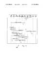
- the inheritance and association diagram for the UMS system as a wholeis shown in FIG. 8 , generally indicated at 180 .
- the UMSis indicated at 181 , with the left hand side of the diagram generally showing the configuration manager logic and the right hand side of the diagram generally showing the information manager logic.
- Configuration manager 182preferably, spans multiple layers. As shown, in the prototype implementation, service management layer configuration manger (SMLcm) 184 and network management layer configuration manager (NMLcm) 185 communicate with configuration manager logic 182 . Further, preferably, information manager logic 183 spans several layers. Service management layers information manager (SMLim) 187 and network management layer information manager (NMLim) 188 communicate with information manager logic 183 .
- the element management layer configuration manager (EMLcm)is indicated at 186 , while the element management layer information manager (EMLim) in indicated at 189 .
- the actual configuringis done by the EMLcm 186 , to provide communication between, for example, termination point 194 a and network access point 194 b .
- the various element managers(for the various hardware platform developments) are indicated at 190 , 191 , 192 , 193 .
- UMS 181affects control of element manager 190 , 191 , 192 , 193 with various communications involving configuration manager logic 182 , information manger logic 183 , and the associated cm and im components at the various levels.
- the element managersmay use various specific techniques suited for the particular hardware platform, as needed, such as, for example, socket 195 and result cloud 197 .
- Socket 195allows direct communication with UMS 181 of command 196 , when required.
- network management logic information manger (NMLim) 188has access to user logical link routing information at cloud 198 , and a log 199 may be used to track operation of UMS 181 .
- NMLimnetwork management logic information manger
- the Catalyst 5000 element manager classuses a state variable to track what state the element is in.
- the statesinclude: Initialized 202 , Enabled 204 , Enabled 206 , WAN-Initialized 208 , and idle 210 . These states map to the different modes the element can be in. For instance, to configure an ATM card, the element manager must enter an ATM session mode and then config mode.
- control methodssuch as initialize, shutdown, xconCreate and xconDelete
- operation methodsverify the element is in the proper state before executing any commands on the element. They modify and maintain the state as the commands progress.
- the operation methodsare more of the low-level methods, and assume that the element is already in the proper state. This allows for only a small number of methods to be concerned about the state of the element, and operation methods to only be concerned with their specific task.
- createVlanCreates a Vlan, associating it with a specific Ethernet port portEnable Enables a port after the Vlan has been created createATMPvc Creates an ATM PVC within the ATM card bindAtmVlan Binds a VLAN to an ATM PVC within the ATM card unbindAtmVlan Unbinds a VLAN from an ATM PVC deleteAtmPvc Deletes an ATM PVC deleteVlan Deletes a Vlan enable Puts the element into enabled mode (i.e., write mode) session Puts the element into a session mode with an ATM card sessionEnable Puts the element into a session enabled mode (i.e.
- sessionConfigPuts the element into configuration mode for the ATM card sessionEndConfig Exits the ATM card configuration mode sessionDisable Disables write mode for the ATM card sessionQuit Takes the element back out of session mode disable Disables write mode of the element
- Communication with a Catalyst 5000is performed with a TCP/IP client socket supported by the Socket class.
- the Socket classuses the sendRequest method to communicate with the element.
- sendRequesttakes two arguments. The first is a string that is sent to the element. The second is the expected response from the element. sendRequest sends the first string and reads from the socket until it receives a response. If the response is not what is expected, it will return an error condition which the element manager can then act upon. Otherwise, it returns a successful condition.
- the configuration of the Newbridge 36170is performed by using the Newbridge 46020, Newbridge ConnectExec, and DSET products.
- the 46020connects to the 36170 via an Ethernet connection running a proprietary protocol CPSS.
- the ConnectExec softwareprovides a CMIP interface to the DSET package and a proprietary interface to the 46020.
- the DSET packageprovides a set of C++ synchronous interface calls which will create/configure and delete ATM PVCs.
- the supported functions provided by DSETare DSET_init( ) DSET_shutdown, createGroomedCircuit( ) setGroomedCircuit, and deleteGroomedCircuit.
- the configuration of the 36170was performed for the prototype using a set of C++ synchronous system calls provided by DSET which are compiled and linked into the UMS code via object files.
- the NMLcm within the UMSinstantiates a NB46020EM (element manager for Newbridge networks).
- the initialization processis started by the NMLcm, where upon the NB46020EM establishes communication with the DSET agent via a C++ system call.
- the NB46020EM initialize methodis invoked by the NMLcm and will make a DSET_init( ) call to the DSET agent which will establish a CMIP association with the ConnectExec agent.
- the ConnectExec agentcommunicates with the 46020 via a proprietary mechanism. Once the association is performed, connect and disconnect requests can be received from the SML.
- the SMLwill send service requests down to the UMS (NMLcm), where upon the NMLcm (after conferring with the NMLim) will transmit the proper nllCreate messages to the EMLcms.
- NMLcmUMS
- the nllCreate messagewill be mapped to the proper xconCreate message.
- the xconCreate methodwill first verify that the route requested does not already exist. If the route does not exist, then a createGroomedCircuit, and setGroomedCircuit commands are sent. A similar procedure is followed for service deletion requests.
- the SMLwill send a service disconnect request down to the UMS (NMLcm), where upon the NMLcm (after conferring with the NMLim) will transmit the proper nllDelete messages to the EMLcms. In the case of the NB46020EM, the nllDelete message will be mapped to the proper xconDelete message.
- the xconDelete methodwill transmit a deleteGroomedCircuit.
- the route tableis updated by setting the route condition to ⁇ 1 (no route).
- a persistent storeis required which maps routes to TrailIds. Two methods exist to update and read the persistent store: NB46020EM::xconGetRoute( ) and NB46020EM::xconSetRoute.
- the hardware configuration and control of the Newbridge networkconsists of the following.
- the 46020 and ConnectExec softwareare loaded on one SPARCstation.
- the DSET software and UMS softwarereside on a second SPARCstation.
- the DSET software and ConnectExeccommunicate using CMOT (CMIP over TCP/IP).
- the configuration of the Cascade 9000is performed by using the Cascade C++ Provisioning server and client mechanism.
- the CascadeView/Sybase systemconnects to the Cascade 9000 via an Ethernet connection.
- the CascadeView/Sybase machinealso is running the Provisioning Server software which uses a TCP/IP communication to the client-side software which is integrated as part of the prototype UMS software package.
- the NMLcm within the UMSinstantiates a CascEM (element manager communication with Cascade Provisioning Server).
- the initializationoccurs and the CascEM initiates a session to the Cascade Provisioning Server.
- the initializationwill place the Cascade Provisioning Server into the mode of operation and ready to accept any configuration commands.
- the SMLwill send service requests down to the UMS (NMLcm), where upon the NMLcm (after conferring with the NMLim) will transmit the proper nllCreate messages to the EMLcms.
- the nllCreate messagewill be mapped to the proper xconCreate message.
- the xconCreate methodwill transmit the proper commands to the Cascade Provisioning Server.
- a Frame Relay/ATM Service Interworking PVCis constructed as an object and stored in the Cascade 9000 and Sybase database.
- the SMLwill send a service disconnect request down to the UMS (NMLcm), whereupon the NMLcm (after conferring with the NMLim) will transmit the proper nllDelete messages to the EMLcms.
- the nllDelete messagewill be mapped to the proper xconDelete message.
- the xconDelete methodwill delete the Frame Relay/ATM Service Interworking PVC from the Cascade 9000 and the Sybase database.
- the CascEMsupports a shutdown method, which will close the session with the Cascade Provisioning Server.
- the configuration of the Cisco 7200was performed using an element manager developed for the present invention.
- the element manager in productionwould most likely be software such as CiscoWorks.
- the NMLcm within the UMSinstantiates a Cisco7200EM (element manager for Cisco7200).
- the initializationoccurs and the Cisco7200EM initiates a Telnet session to the Cisco7200.
- the initializationwill place the Cisco 7200 into the EXEC mode of operation and ready to accept any configuration commands.
- the SMLwill send service requests down to the UMS (NMLcm), whereupon the NMLcm (after conferring with the NMLim) will transmit the proper nllCreate messages to the EMLcms.
- NMLcmUMS
- the nllCreate messagewill be mapped to the proper xconCreate message.
- the xconCreate methodwill transmit the proper commands to the Cisco 7200 via the Telnet connection.
- the SMLwill send a service disconnect request down to the UMS (NMLcm), whereupon the NMLcm (after conferring with the NMLim) will transmit the proper nllDelete messages to the EMLcms.
- NMLcmUMS
- the nllDelete messagewill be mapped to the proper xconDelete message.
- the xconDelete methodwill transmit the proper command sequence to the Cisco 7200 via the Telnet connection.
- the Cisco7200EMsupports a shutdown method, which will disconnect the Telnet session with the Cisco 7200.
- the prototype configurationrequired the Cisco 7200 to be configured as a bridge.
- a single bridge group which connected Frame Relay PVCs to a single Ethernet portwas configured ahead of time.
- the Cisco7200EMcould have performed this function as part of the initialization process.
- the connect and disconnect requestsmapped into adding and removing Frame Relay DLCI from the bridge group.
- the configuration of the Cisco 7200is listed below.
- boot systemflash slot0:c7200-j-mz.111-9.CA1.bin
- the state machine for the configuration of the Cisco 7200 element mangeris shown in FIG. 10 , at 220 .
- the element managerincludes initialization logic 222 and illustrates various states for the element manager including an idle state 224 , a connected state 226 , a read-only state 228 , a password-wait state 230 , and an exec-mode 232 .
- Execution modeallows deletion of cross connections as shown at block 234 and creation of cross connections as shown at block 237 .
- Cross connection deletion logic 234includes configuration logic 235 and 236
- cross connection creation logic 237includes configuration logic 238 and 239 .
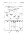
- FIG. 11a block diagram illustrating the functional design of the prototype implementation of the present invention is generally indicated at 240 .
- service session manager 242is in communication with the service management layer.
- the service management layerincludes a configuration manager (SMLcm) 244 and an information manager (SMLim) 246 .
- UMSin accordance with the present invention, provides communications between the service management layer and the lower layers.
- the network management layerhas a configuration manager side (NMLcm) 248 and an information manager side (NMLim) 250 .
- the element management layerhas a configuration manager side (EMLcm) 252 and an information manager side (EMLim) 254 .
- EMLcmconfiguration manager side
- EMLiminformation manager side
- a network management system of the present inventionconfigures a network connection between first and second service access points at the service management layer as follows.
- SSM 242requests the creation of a service having a specified service type, between an A user access point and a Z user access point. In a prototype, the request is represented as follows:
- the requestis received by the service management layer configuration manager (SMLcm) 244 .
- a service management layer information manager (SMLim) 246may perform some route analysis at the service management level, before the create Service request is passed to the network management layer in the form of a user logical link (ull or ULL) creation request.
- the ull creation requesthas the following format:
- the ull creation requestis received by the network management layer configuration manager (NMLcm) 248 .
- NMLcm 248queries the network management layer information manager (NMLim) 250 to determine a logical route.
- NMLcmnetwork management layer configuration manager
- NMLimnetwork management layer information manager
- the ull route requesttakes the following format:
- NMLim 250returns a ull route to NMLcm 248 . Based on the returned route, NMLcm 248 begins to request network logical links. In the prototype, NMLcm 248 requests the first network logical link using the following request format:
- the element management layerincludes element management layer configuration manager (EMLcm) 252 and element management layer information manager (EMLim) 254 .
- EMLcmelement management layer configuration manager
- EMLimelement management layer information manager
- NMLcmcommunicates with an information manager that spans both the network management layer with NMLim 250 and the element management layer with EMLim 254 (in addition to, as shown the service management layer with SMLim 246 ).
- communications between the configurations manager and the information managermay occur at and/or across various layers of the overall communication model.
- the particular connections between the configuration manager and the information manager shown in FIG. 11are not meant to be limiting, but are used to facilitate an understanding of the prototype embodiment of the present invention.
- the route received from the information manageris made up of links over the network from the first point (the A point) to the second point (the Z point), preferably in accordance with the equations stated previously.
- a network to network link(nnl or NNL) connects a pair of subnets having elements of different types, and a network logical link (nll or NNL) provides a path across a subnet.
- the nll and nnl linksare provided by NMLim 250 .
- EMLim 254provides more specific routing information, such as port and virtual circuit information.
- configuration manager 248requests the corresponding element management layer configuration manger 252 to program the subnet element 256 (at each subnet, with the appropriate element manager) in accordance with the routing information obtained from the information manager.
- EMLcm 252responds to the network logical link creation request by requesting the creation of a cross connection in the following format:
- NLLnetwork logical link
- EMLcm 252In response to this next logical link (NNL) creation request, EMLcm 252 (in accordance with information from EMLim 254 requests the creation of appropriate cross connects, and in the prototype, uses the following format:
- nnllCreate(networkType,NAP_A,NAP_Z)
- EMLcm 252continues to make cross connection creation request to elements 256 , and in the prototype, the last cross connection creation request is made in the following format:
- n+1xcon(elementType, PORT_A,PORT_B)
- the various network logical linksmay each have any number of cross connections, and that the prototype configuration of network logical links using n+1 cross connections is nearly an example.
- UMS 282may be accessed through a variety of interfaces.
- a provisioning tool 284is controlled through a workstation 286 to access UMS 282 .
- workstation 286may have a graphical user interface made in accordance with the present invention to facilitate access to UMS 282 by displaying the provisioning tool graphically.
- UMS 282could receive signals from other devices, such as a service order processor, and so on, and is not particularly limited to receiving control commands through a graphical user interface (GUI).
- GUIgraphical user interface
- UMS 282provides the interface to the network management layer 290 , which includes a configuration manager and an information manager. As mentioned previously, preferably the information manager and the configuration manager have functionality extending to lower layers.
- the various element managers 292access the various network elements 294 as described previously.
- FIG. 13shows an initialize object diagram, showing the associated process flow during object initiation, with the flow diagram being generally indicated at 340 .
- FIG. 14generally indicated at 360 , is an initialize message diagram.
- FIGS. 13 and 14are best understood when viewed together in light of the below listed initialization process for the prototype.
- NMLcmcreateNMLcm( )—( 362 )—The network management layer configuration manager (NMLcm) is created.
- NMLimcreate NMLim( )—( 364 )
- NMLimnetwork management layer information manager
- EMLcmsThe element management layer configuration managers
- path trace object 382 at the SSMsends a request to the NMLcm 384 , preferably (in the prototype) in the following format:
- NMLcm 384in response to the path trace request, passes a route query to NMLim 386 .
- the route queryis preferably (in the prototype) in the following format:
- NMLim 386returns the path as a route list 388 , preferably in a link list format as described previously herein.
- FIG. 16generally indicated at 400 is a provision object diagram.
- FIG. 17generally indicated at 420 , is a provision message diagram.
- FIGS. 16 and 17are best understood when viewed together in light of the below listed provision process.
- NMLcmdetermines quality of service for the network connection being constructed.
- NMLcm 406requests a route from the information manager, and as illustrated, from the NMLim 407 ; the route is returned as a linked list.
- NMLcm 406requests element manager 410 to create a network logical link across the subnet.
- element manager 410creates appropriate cross connections.
- NMLcm 406requests element manager 412 to create a network logical link across the subnet.
- NMLcm 406requests element manager 414 to create a network logical link across the subnet.
- NMLcm 406requests element manager 416 to create a network logical link across the subnet.
- FIGS. 18 and 19are a topology object diagram and a topology message diagram, respectively.
- the topology object diagramis generally indicated at 440 .
- the element managers 441 , 442 , 443 , 444create cross connects in their respective subnets, and information is logged into log object 450 .
- element manager 441creates a cross connection (message 445 , FIG. 19 ) and the status 446 of the connection is logged at 450 .
- Log 450sends message 451 ( FIG. 19 ) to socket 452 .
- the cross connect status 454is presented to SSM 456 .
- SSM 456updates the graphical user interface (GUI) 458 by sending update GUI message 457 ( FIG. 19 ).
- GUIgraphical user interface
- the exemplary prototype Umbrella Management Systemis responsible for communication through well-defined interfaces to the SML and the EML.
- Operations, in the example (as other implementations may vary)are as follows.
- the exemplary GUI for the UMS prototypemay send the following exemplary commands to the UMS:
- createService(internetAccess, ⁇ epA>, ⁇ epZ>)This method makes a request to the UMS to create a Quality of Service (QoS) of type “internet access” with the associated end points A and Z.
- QoSQuality of Service
- playMovie( ⁇ filename>)This method is invoked when a video clip is to be played on the GUI. A file name is passed on the UMS and a shell command is executed to play the desired video clip.
- GUI implementationfor the prototype UMS, a two part application was supported by a graphical display.
- the first partwas the UMS daemon, and the second part was the actual provisioning tool.
- specific details of the exemplary GUIare described. It is appreciated that the GUI (and the associated applications) may vary based on the particular implementation, and that the GUI of the present invention is to be construed as much broader than the specific description below. Further, it is appreciated that a more general description of the GUI was given previously, near a more general description of the UMS.
- the UMS daemon and the provisioning toolare run on a workstation. Entry of an appropriate user name and password brings up the common desktop environment (CDE). The commands necessary to start the UMS and provisioning tool are all accessible at the CDE menubar at the bottom of the screen.
- the UMS daemon and provisioning toolcould also be started from a UNIX shell (when the implementation is in a UNIX environment). Again, the particular two module UNIX example is the way that the GUI was implemented for the prototype. Of course, other techniques may be used in the alternative, and the description below is for a specific example.
- the menubaris generally indicated at 500 .
- Clicking on the up-arrow 502 above the Interop icon 504 on the menubar 500opens the Interop applications subpanel ( FIG. 21 , number 510 ).
- clicking on the whole !nchilada sombre icon 512starts the UMS daemon, sending its output to a log file.
- the log fileis called /tmp/ums.log.
- ⁇ NUM>is a number that increases with each invocation of the UMS daemon.
- the provisioning toolis started by clicking on icon 514 .
- the provisioning toolin the example, is a JAVA applet that runs within a browser or virtual machine.
- a JAVA appletis an exemplary way to implement the tool, and other approaches, such as ACTIVE X may be taken instead.
- Clicking on the icon 514launches the browser or virtual machine, preferably automatically, and starts the provisioning tool.
- the display for the provisioning toolpreferably includes a plurality of tabs: introduction tab 522 , provision tab 524 , topology tab 526 , utility tab 528 , help tab 530 , and about tab 532 .
- the provisioning tool itselfis generally indicated at reference numeral 520 .
- Introduction tab 522presents a number of buttons/icons 534 that can be activated to bring up introduction materials such as text or multimedia.
- the provisioning tabprovides information at the service management layer (SML).
- SMLservice management layer
- the system user that is provisioning the serviceonly needs to provide first and second service access points (SAPs).
- SAPsservice access points
- end point Ais selected, as directed by the graphic display in provision tab 524 .
- the Z end pointis selected at blanks 542 .
- end point Ais an Internet service provider (ISP), or a company host site.
- End point Zrepresents the subscriber that is trying to connect to an ISP or company host site.
- the subscriberis preferably identified by his or her unique phone number (or address or other equivalent identifier, as appropriate). Each of the phone numbers on the list may correspond to each different phone number accessible by the user's computer.
- the graphical interfacedirects the user, that is, gives the user the option to, initiate a connection build.
- a connection buildis initiated by pressing the green light 546 of the stop light symbol shown in the bottom of the provision tab 524 . Pressing button 546 immediately brings up the topology tab ( FIG. 24 , number 526 ) and a view of the network management layer (NML) ( FIG. 25 , generally indicated at 560 ). The red light 548 in FIG. 23 is pressed to terminate a previously built connection.
- the useris given live feedback (in preferred embodiments) while the service is being provisioned.
- the cloud 554turns yellow to indicate that the service is in a pending state.
- the ISP end of the connectionis indicated at 550
- the subscriber endis indicated at 552 .
- the various icons 562 , 564 , 566 , 568 in the management layer 560will turn yellow as the connection across each subnetwork pends. That is, in the network management layer 560 , an icon corresponds to each appropriate subnetwork in the end to end connection being made.
- the example illustratedshows the four icons for the four subnets of the prototype, but of course, this is just an example.
- Network Management Layer 560appropriately displays all subnets along the route between the A and Z ends of the connection.
- the icon for that subnetworkturns green. If unsuccessful, the icon turns red. After each subnet has been provisioned (turns green), the cloud 554 in FIG. 24 will change color to green or red to indicate the result of the entire process. If cloud 554 is green, then installation of the network connection was successful and clean.
- the element management layer for a subnetis generally indicated at 570 .
- the system usermay expand any one of the subnet icons of FIG. 25 to show the corresponding element management layer.
- the element management layerincludes a series of crossconnects 572 and physical links 574 forming a network logical link.
- provisioning informationis generally indicated at 580 and includes (in an ATM example) virtual path identifier/virtual channel identifier (VPI/VCI) information 582 , 586 , and port information 584 , 588 .
- VPN/VCIvirtual path identifier/virtual channel identifier
- the utilities tab 528shows several optional utilities that may be provided with the provisioning tool.
- utilitiesmay be provided for connecting and disconnecting the provisioning tool from the UMS daemon, with these utilities being activated by connect and disconnect buttons 602 and 604 , respectively.
- a shutdown button 606may be provided to cause both the provisioning tool and the UMS daemon to exit. Thereafter, a browser or virtual machine or other running process that was assisting the provisioning tool should also be shutdown, including the menubar, prior to restarting the different system processes to reattempt to provision service.
- FIG. 29scalable bit rate service selection, which is present in some implementations of the present invention, is illustrated.
- the system 620 in FIG. 29is preferably the UMS shown in FIGS. 1 and 2 , with FIG. 29 having the UMS running at server 622 .
- the below descriptiondescribes a preferred network system (the UMS) for use with methods and software for scalable bit rate service selection, and that these embodiments of the invention are to be construed in accordance with the broader summary given previously, with the below description explaining the preferred embodiments.
- Scalable service selection for XDSLallows customers to self-select their desired access service speeds and features via a (preferably web) interface to the service platform, which is preferably the UMS described previously.
- These embodiments of the inventionprovide on-line access control through a customer's public or private network connection.
- Methods and proceduresimplement scalable rate selection and control the user or customer's XDSL connection by throttling customer access PVCs at the ATM assigned switch port.
- Rate adaptive modemsin combination with embodiments of the present invention that provide customer controlled PVC throttling mitigate additional truck-rolls and technician dispatches via remote network provisioning of service upgrades to higher (or lower) classes of service.
- embodiments of the present inventionprovide on-line access to customer applications such as provisioning control, and fault and performance analysis. Examples of hardware having rate adaptive modem capabilities are the Cisco 605PCI ADSL modem and the Cisco 675 ADSL router, available from Cisco Systems.
- the system of the present invention in FIG. 29preferably operates from the customer's premise via a graphical interface, either web-based or provided to the customer with the service. Through that interface, customers have access via the Internet if they have a public service, or via an intranet or a private connection, back to a web-based browser or server environment 622 . Access to gateway bus 624 preferably is controlled by user authentication 626 . Authentication and security provisions are preferably incorporated so that individual customers can be discretely identified and given access and control to only the services or capabilities that the customer subscribes to or currently has in service. After authentication of the customer, various different levels of controlled access may be granted to the customer to allow access to the system environment, through gateway 628 .
- the service management layerincludes the SML communication bus 630 , and various applications such as trouble ticketing 632 , provisioning 634 , billing 636 , network statistics 638 , service access 640 , and customer inventory 642 .
- the applicationsare specific applications that customers would have access to and can write to which give the customers control of functional areas. For example, through the trouble ticketing system in the SML layer, which in turn communicates with the fault manager in the network management layer, on-line access to the trouble ticketing system is available so that customers can create, add or add logs to, or delete or close trouble tickets.
- NML communication bus 650provides communication with various databases or functional areas.
- the customermay communication over the NML bus 650 with fault manager 652 , configuration manager 654 , account manager 656 , performance managers 658 , security manager 660 and topology manager 662 .
- GUIgraphical user interface
- the customercould also change his or her speed. For example, if the customer is working at 256 kbps, he or she could change to 512 kbps or 768 kbps and the application has the ability to interface with the UMS to determine if that type of speed is available to the customer in advance. So, for example, there may be a screen provided where the customer could hit a button and go on to find out what bandwidth options are available. The customer could then select one of the different speeds offered and send a message back to the system server indicating the speed selected such that the system may remotely provision the appropriate switch for it to throttle the PVC to the customer.
- the systemshould perform a security authentication to give the customer permission to make changes. Further, preferably, after the selection is made, the system changes the customer's billing structure.
- preferred embodiments that provide scalable bit rate by throttling the PVC at the ATM switch portallow the customer to select a time duration for the selected bandwidth. For example, the customer could select an increased bandwidth for the next five minutes, for one day, or permanently.
- the account managerprovides information such as a profile of the current set-up of an account, current services billed for, and month-to-date billing data.
- the performance managerprovides information about how the connection is operating, giving the customer the ability to do self-help and diagnose problems. Through the performance manager, a customer is able to tell if problems are at the customer end or the host end.
- the security managerprovides the ability to determine who can have access to an account, who can change the account, and who has permission to read and write to the account.
- topologyprovides the ability for one to look at the entire network to see what the network looks like and the current connections, including what customers are provisioned for and what the bandwidth settings currently available to those subscribers are.
- the element management layeris the vendor provided well-defined interfaces. Every supplier of network hardware should provide a very well-defined interface (type of connection and how it is to behave) so that these applications can work in accordance with the present invention at the higher layers.
- the communication busis indicated at 370 , and the element managers at 672 , 674 , 676 .
- the clouds 682 , 684 , 686represent the elements.
- a central office switchis in the cloud format and the element management system of the central office is a software application that the supplier of the switch provides or that is written in accordance with the well-defined interface to control provisioning of the switches.
- the scalable service rate selection in accordance with the present inventionallows a user 694 from his or her home or office computer 692 to communicate over a network 690 (Internet or intranet) with server 622 .
- Server 622allows the user to remotely provision a switch in his or her PVC to throttle the bandwidth.
- server 622operates as the UMS described herein.
- a suitable technique for throttling the PVCis to throttle the switch at the ATM interface port (or at the DSLAM when the implementation is ATM over DSL).
- a method of the present invention for providing a customer the ability to remotely provision a network switch and throttle his or her PVCis generally indicated at 700 .
- the graphical user interfaceis established at the user location.
- the useris authenticated.
- the useris directed to select a desired permanent virtual circuit (PVC) bandwidth (or bit rate).
- PVCpermanent virtual circuit
- the system serverreceives a message indicating the user selection.
- the local switchis remotely provisioned to throttle the user PVC in accordance with the selected bandwidth.
- the throttling of the PVCmay be performed for a selected period of time, as generally indicated at 720 in FIG. 31 .
- the useris directed to select a time duration for the selected PVC bandwidth.
- the system serverreceives a message indicating the user's selected time (and the selected bandwidth).
- PVCis throttled to the selected bandwidth for the selected amount of time.
- the PVCis then throttled to a previous bandwidth after the period of time expires.
- the customermay select a desired bandwidth (for example, a customer normally receiving 256 kbps may select a desired PVC bandwidth of 512 kbps), and a desired time (for example, the customer may wish to have the increased bandwidth for one hour or one day).
- the PVCis throttled to the selected bandwidth for the desired period of time, and thereafter, the PVC is throttled to the previous bandwidth.
Landscapes
- Engineering & Computer Science (AREA)
- Computer Networks & Wireless Communication (AREA)
- Signal Processing (AREA)
- Human Computer Interaction (AREA)
- Data Exchanges In Wide-Area Networks (AREA)
Abstract
Description
- command(<parameters>)
| createVlan | Creates a Vlan, associating it with a specific | ||
| Ethernet port | |||
| portEnable | Enables a port after the Vlan has been created | ||
| createATMPvc | Creates an ATM PVC within the ATM card | ||
| bindAtmVlan | Binds a VLAN to an ATM PVC within the | ||
| ATM card | |||
| unbindAtmVlan | Unbinds a VLAN from an ATM PVC | ||
| deleteAtmPvc | Deletes an ATM PVC | ||
| deleteVlan | Deletes a Vlan | ||
| enable | Puts the element into enabled mode | ||
| (i.e., write mode) | |||
| session | Puts the element into a session mode with | ||
| an ATM card | |||
| sessionEnable | Puts the element into a session enabled mode | ||
| (i.e. write mode for ATM) | |||
| sessionConfig | Puts the element into configuration mode | ||
| for the ATM card | |||
| sessionEndConfig | Exits the ATM card configuration mode | ||
| sessionDisable | Disables write mode for the ATM card | ||
| sessionQuit | Takes the element back out of session mode | ||
| disable | Disables write mode of the element | ||
- control: The control method is called by the main routine upon initialization of the lower layers (NML and EML instances) and initialization of the communications path to the SML. The control method consists of an event loop which looks for requests from the SML (and possibly for requests and/or events from the lower layers).
- createNMLcm: Return class is the NMLcm ID.
- createSMLcomm: Creation of the communications path to the SML interface.
- deleteNMLcm
- deleteSMLcomm
- initialize: The initialize method will be invoked from the main( ) routine. The UMS will then create the NML entities and open a communication channel (for example, a socket) to the SML.
- shutdown: shutdown is called from the main routine. The UMS will then issue a shutdown method to the NMLcm, and if successful, delete it.
Claims (10)
Priority Applications (2)
| Application Number | Priority Date | Filing Date | Title |
|---|---|---|---|
| US09/469,206US7966388B1 (en) | 1998-12-31 | 1999-12-21 | Network management system and graphical user interface |
| US13/156,069US8539032B2 (en) | 1998-12-31 | 2011-06-08 | Network management system and graphical user interface |
Applications Claiming Priority (5)
| Application Number | Priority Date | Filing Date | Title |
|---|---|---|---|
| US11442798P | 1998-12-31 | 1998-12-31 | |
| US11442898P | 1998-12-31 | 1998-12-31 | |
| US11442498P | 1998-12-31 | 1998-12-31 | |
| US11442998P | 1998-12-31 | 1998-12-31 | |
| US09/469,206US7966388B1 (en) | 1998-12-31 | 1999-12-21 | Network management system and graphical user interface |
Related Child Applications (1)
| Application Number | Title | Priority Date | Filing Date |
|---|---|---|---|
| US13/156,069ContinuationUS8539032B2 (en) | 1998-12-31 | 2011-06-08 | Network management system and graphical user interface |
Publications (1)
| Publication Number | Publication Date |
|---|---|
| US7966388B1true US7966388B1 (en) | 2011-06-21 |
Family
ID=27493956
Family Applications (3)
| Application Number | Title | Priority Date | Filing Date |
|---|---|---|---|
| US09/469,199Expired - LifetimeUS6903755B1 (en) | 1998-12-31 | 1999-12-21 | Network management system and graphical user interface |
| US09/469,206Expired - Fee RelatedUS7966388B1 (en) | 1998-12-31 | 1999-12-21 | Network management system and graphical user interface |
| US13/156,069Expired - Fee RelatedUS8539032B2 (en) | 1998-12-31 | 2011-06-08 | Network management system and graphical user interface |
Family Applications Before (1)
| Application Number | Title | Priority Date | Filing Date |
|---|---|---|---|
| US09/469,199Expired - LifetimeUS6903755B1 (en) | 1998-12-31 | 1999-12-21 | Network management system and graphical user interface |
Family Applications After (1)
| Application Number | Title | Priority Date | Filing Date |
|---|---|---|---|
| US13/156,069Expired - Fee RelatedUS8539032B2 (en) | 1998-12-31 | 2011-06-08 | Network management system and graphical user interface |
Country Status (3)
| Country | Link |
|---|---|
| US (3) | US6903755B1 (en) |
| AU (3) | AU2715600A (en) |
| WO (3) | WO2000039699A1 (en) |
Cited By (54)
| Publication number | Priority date | Publication date | Assignee | Title |
|---|---|---|---|---|
| US20080222285A1 (en)* | 2007-03-07 | 2008-09-11 | Hickey James P | Configurable network device user interface |
| US20090248376A1 (en)* | 2006-11-08 | 2009-10-01 | Silva Gabriel A | Complex Network Mapping |
| US20090268741A1 (en)* | 2007-04-30 | 2009-10-29 | Zhang Junguang | Access device and method for communication between master shelf and slave shelf |
| US20100138688A1 (en)* | 2006-08-19 | 2010-06-03 | Sykes Edward A | Managing service levels on a shared network |
| US8595478B2 (en) | 2000-07-10 | 2013-11-26 | AlterWAN Inc. | Wide area network with high quality of service |
| US20140053184A1 (en)* | 2004-04-05 | 2014-02-20 | Comcast Cable Holdings, Llc | Device Provisioning |
| US20140337500A1 (en)* | 2013-02-26 | 2014-11-13 | Zentera Systems, Inc. | Secure cloud fabric to connect subnets in different network domains |
| US20150113416A1 (en)* | 2013-10-18 | 2015-04-23 | Power-All Networks Limited | Transmission path management device |
| US9069436B1 (en)* | 2005-04-01 | 2015-06-30 | Intralinks, Inc. | System and method for information delivery based on at least one self-declared user attribute |
| US9148417B2 (en) | 2012-04-27 | 2015-09-29 | Intralinks, Inc. | Computerized method and system for managing amendment voting in a networked secure collaborative exchange environment |
| US9253176B2 (en) | 2012-04-27 | 2016-02-02 | Intralinks, Inc. | Computerized method and system for managing secure content sharing in a networked secure collaborative exchange environment |
| US9251360B2 (en) | 2012-04-27 | 2016-02-02 | Intralinks, Inc. | Computerized method and system for managing secure mobile device content viewing in a networked secure collaborative exchange environment |
| US9516700B1 (en) | 2014-09-25 | 2016-12-06 | Google Inc. | Cloud-based controller for managing access points |
| US9514327B2 (en) | 2013-11-14 | 2016-12-06 | Intralinks, Inc. | Litigation support in cloud-hosted file sharing and collaboration |
| US9544707B2 (en) | 2014-02-06 | 2017-01-10 | Sonos, Inc. | Audio output balancing |
| US9549258B2 (en) | 2014-02-06 | 2017-01-17 | Sonos, Inc. | Audio output balancing |
| US9553860B2 (en) | 2012-04-27 | 2017-01-24 | Intralinks, Inc. | Email effectivity facility in a networked secure collaborative exchange environment |
| US9613190B2 (en) | 2014-04-23 | 2017-04-04 | Intralinks, Inc. | Systems and methods of secure data exchange |
| US9658820B2 (en) | 2003-07-28 | 2017-05-23 | Sonos, Inc. | Resuming synchronous playback of content |
| US9681223B2 (en) | 2011-04-18 | 2017-06-13 | Sonos, Inc. | Smart line-in processing in a group |
| US9712624B2 (en) | 2013-02-26 | 2017-07-18 | Zentera Systems, Inc. | Secure virtual network platform for enterprise hybrid cloud computing environments |
| US9729115B2 (en) | 2012-04-27 | 2017-08-08 | Sonos, Inc. | Intelligently increasing the sound level of player |
| US9734242B2 (en) | 2003-07-28 | 2017-08-15 | Sonos, Inc. | Systems and methods for synchronizing operations among a plurality of independently clocked digital data processing devices that independently source digital data |
| US9749760B2 (en) | 2006-09-12 | 2017-08-29 | Sonos, Inc. | Updating zone configuration in a multi-zone media system |
| US9748646B2 (en) | 2011-07-19 | 2017-08-29 | Sonos, Inc. | Configuration based on speaker orientation |
| US9756424B2 (en) | 2006-09-12 | 2017-09-05 | Sonos, Inc. | Multi-channel pairing in a media system |
| US9766853B2 (en) | 2006-09-12 | 2017-09-19 | Sonos, Inc. | Pair volume control |
| US9787550B2 (en) | 2004-06-05 | 2017-10-10 | Sonos, Inc. | Establishing a secure wireless network with a minimum human intervention |
| US9977561B2 (en) | 2004-04-01 | 2018-05-22 | Sonos, Inc. | Systems, methods, apparatus, and articles of manufacture to provide guest access |
| US10031716B2 (en) | 2013-09-30 | 2018-07-24 | Sonos, Inc. | Enabling components of a playback device |
| US10033702B2 (en) | 2015-08-05 | 2018-07-24 | Intralinks, Inc. | Systems and methods of secure data exchange |
| US10061379B2 (en) | 2004-05-15 | 2018-08-28 | Sonos, Inc. | Power increase based on packet type |
| US10306364B2 (en) | 2012-09-28 | 2019-05-28 | Sonos, Inc. | Audio processing adjustments for playback devices based on determined characteristics of audio content |
| US10320635B2 (en) | 2009-06-11 | 2019-06-11 | Talari Networks Incorported | Methods and apparatus for providing adaptive private network centralized management system timestamp correlation processes |
| US10348767B1 (en) | 2013-02-26 | 2019-07-09 | Zentera Systems, Inc. | Cloud over IP session layer network |
| US10359987B2 (en) | 2003-07-28 | 2019-07-23 | Sonos, Inc. | Adjusting volume levels |
| US10382401B1 (en) | 2013-02-26 | 2019-08-13 | Zentera Systems, Inc. | Cloud over IP for enterprise hybrid cloud network and security |
| US10484334B1 (en) | 2013-02-26 | 2019-11-19 | Zentera Systems, Inc. | Distributed firewall security system that extends across different cloud computing networks |
| US10613817B2 (en) | 2003-07-28 | 2020-04-07 | Sonos, Inc. | Method and apparatus for displaying a list of tracks scheduled for playback by a synchrony group |
| US10756928B2 (en) | 2016-07-29 | 2020-08-25 | At&T Intellectual Property I, L.P. | Interconnection between enterprise network customers and network-based cloud service providers |
| US10797962B2 (en) | 2014-12-23 | 2020-10-06 | Talari Networks Incorporated | Methods and apparatus for providing adaptive private network centralized management system data visualization processes |
| US11106425B2 (en) | 2003-07-28 | 2021-08-31 | Sonos, Inc. | Synchronizing operations among a plurality of independently clocked digital data processing devices |
| US11106424B2 (en) | 2003-07-28 | 2021-08-31 | Sonos, Inc. | Synchronizing operations among a plurality of independently clocked digital data processing devices |
| US11265652B2 (en) | 2011-01-25 | 2022-03-01 | Sonos, Inc. | Playback device pairing |
| US11294618B2 (en) | 2003-07-28 | 2022-04-05 | Sonos, Inc. | Media player system |
| US11403062B2 (en) | 2015-06-11 | 2022-08-02 | Sonos, Inc. | Multiple groupings in a playback system |
| US11429343B2 (en) | 2011-01-25 | 2022-08-30 | Sonos, Inc. | Stereo playback configuration and control |
| US11481182B2 (en) | 2016-10-17 | 2022-10-25 | Sonos, Inc. | Room association based on name |
| US11650784B2 (en) | 2003-07-28 | 2023-05-16 | Sonos, Inc. | Adjusting volume levels |
| US11894975B2 (en) | 2004-06-05 | 2024-02-06 | Sonos, Inc. | Playback device connection |
| US11995374B2 (en) | 2016-01-05 | 2024-05-28 | Sonos, Inc. | Multiple-device setup |
| US12155527B2 (en) | 2011-12-30 | 2024-11-26 | Sonos, Inc. | Playback devices and bonded zones |
| US12167216B2 (en) | 2006-09-12 | 2024-12-10 | Sonos, Inc. | Playback device pairing |
| US12245009B2 (en) | 2019-07-22 | 2025-03-04 | D&M Holdings Inc. | Wireless audio system, wireless speaker, and group joining method for wireless speaker |
Families Citing this family (42)
| Publication number | Priority date | Publication date | Assignee | Title |
|---|---|---|---|---|
| US6903755B1 (en) | 1998-12-31 | 2005-06-07 | John T. Pugaczewski | Network management system and graphical user interface |
| US6707794B1 (en) | 1999-11-15 | 2004-03-16 | Networks Associates Technology, Inc. | Method, system and computer program product for physical link layer handshake protocol analysis |
| US7415512B1 (en)* | 2001-05-24 | 2008-08-19 | Cisco Technology, Inc. | Method and apparatus for providing a general purpose computing platform at a router on a network |
| US20030005115A1 (en)* | 2001-06-27 | 2003-01-02 | Walker Philip M. | System and method for providing access to a resource |
| US7469279B1 (en) | 2003-08-05 | 2008-12-23 | Cisco Technology, Inc. | Automatic re-provisioning of network elements to adapt to failures |
| US20050050196A1 (en)* | 2003-08-25 | 2005-03-03 | Lucent Technologies Inc. | Method and apparatus for managing and graphically representing elements in a network |
| US7529815B2 (en)* | 2003-11-24 | 2009-05-05 | Cisco Technology, Inc. | Methods and apparatus supporting configuration in a network |
| US8812635B2 (en)* | 2003-12-14 | 2014-08-19 | Cisco Technology, Inc. | Apparatus and method providing unified network management |
| US7350000B2 (en) | 2004-02-25 | 2008-03-25 | International Business Machines Corporation | User interface for representing logical path information and displaying available adapters in a storage subsystem |
| US20050204290A1 (en)* | 2004-03-12 | 2005-09-15 | Eddy Brett P. | System and method for generating distributed application and distributed system topologies with management information in a networked environment |
| USD549720S1 (en)* | 2005-06-30 | 2007-08-28 | Microsoft Corporation | User interface for a portion of a display screen |
| USD549719S1 (en)* | 2005-06-30 | 2007-08-28 | Microsoft Corporation | User interface for a portion of a display screen |
| US7739605B2 (en)* | 2005-09-09 | 2010-06-15 | Netapp, Inc. | System and/or method relating to managing a network |
| US7840902B2 (en)* | 2005-10-26 | 2010-11-23 | Hewlett-Packard Development Company, L.P. | Method and an apparatus for automatic creation of secure connections between segmented resource farms in a utility computing environment |
| US20070106947A1 (en)* | 2005-11-08 | 2007-05-10 | International Business Machines Corporation | Method, system, and program product for selectively emphasizing a portion of a graphical display |
| US20070268294A1 (en)* | 2006-05-16 | 2007-11-22 | Stephen Troy Eagen | Apparatus and method for topology navigation and change awareness |
| US7821941B2 (en)* | 2006-11-03 | 2010-10-26 | Cisco Technology, Inc. | Automatically controlling operation of a BRAS device based on encapsulation information |
| US9253033B2 (en)* | 2006-12-22 | 2016-02-02 | Verizon Patent And Licensing Inc. | Network management system integrated with provisioning system |
| EP2019520A1 (en)* | 2007-07-25 | 2009-01-28 | Nokia Siemens Networks Oy | Method of determining network elements for synchronous data transmission, control element, control system and computer program product |
| US20090055748A1 (en)* | 2007-08-23 | 2009-02-26 | International Business Machines Corporation | System and method for flexibly selecting and visualizing configuration changes over time |
| US9529689B2 (en) | 2009-11-30 | 2016-12-27 | Red Hat, Inc. | Monitoring cloud computing environments |
| US8645854B2 (en)* | 2010-01-19 | 2014-02-04 | Verizon Patent And Licensing Inc. | Provisioning workflow management methods and systems |
| EP2647164B1 (en)* | 2010-12-01 | 2017-05-17 | Xieon Networks S.à r.l. | Method and device for service provisioning in a communication network |
| US9787607B2 (en)* | 2011-04-04 | 2017-10-10 | Infinera Corporation | End-to-end provisioning of Ethernet Virtual Circuits |
| US20130055091A1 (en)* | 2011-08-23 | 2013-02-28 | Cisco Technology, Inc. | Graph-Based Virtual Data Center Requests |
| US9292279B2 (en)* | 2013-01-22 | 2016-03-22 | Maluuba Inc. | Method and system for creating and managing a dynamic route topography for service oriented software environments |
| USD741355S1 (en)* | 2013-06-27 | 2015-10-20 | Tencent Technology (Shenzhen) Company Limited | Display screen or portion thereof with animated graphical user interface |
| USD740849S1 (en)* | 2013-06-27 | 2015-10-13 | Tencent Technology (Shenzhen) Company Limited | Display screen or portion thereof with animated graphical user interface |
| US9253043B2 (en)* | 2013-11-30 | 2016-02-02 | At&T Intellectual Property I, L.P. | Methods and apparatus to convert router configuration data |
| US10153946B2 (en)* | 2014-04-15 | 2018-12-11 | Centurylink Intellectual Property Llc | Topology engine state tracking |
| US20160112253A1 (en)* | 2014-10-15 | 2016-04-21 | Infinera Corporation | Shared framework for optical network span based graphical applications |
| US20160112277A1 (en)* | 2014-10-15 | 2016-04-21 | Infinera Corporation | Optical channel tracing in a link viewer |
| US10756984B2 (en)* | 2015-04-13 | 2020-08-25 | Wirepath Home Systems, Llc | Method and apparatus for creating and managing network device port VLAN configurations |
| US9948679B2 (en)* | 2015-08-21 | 2018-04-17 | Cisco Technology, Inc. | Object-relation user interface for viewing security configurations of network security devices |
| EP3356919B1 (en) | 2015-10-02 | 2025-04-09 | Nokia Solutions and Networks Oy | Managing the graceful termination of a virtualized network function instance |
| US10237137B2 (en) | 2016-09-12 | 2019-03-19 | Edward Linn Helvey | Remotely assigned, bandwidth-limiting internet access apparatus and method |
| USD817313S1 (en) | 2016-12-22 | 2018-05-08 | Michael Horito | Network access point |
| US10439895B2 (en) | 2017-01-31 | 2019-10-08 | Salesforce.Com, Inc. | Dynamic selection of channels for incoming communication |
| CN109688000B (en)* | 2018-12-13 | 2022-06-14 | 四川天邑康和通信股份有限公司 | Method for simultaneously accessing multiple IPTV network management server platforms |
| US11055191B2 (en)* | 2019-05-17 | 2021-07-06 | Citrix Systems, Inc. | Service graph highlights missing nodes and links |
| US11604678B2 (en) | 2020-03-27 | 2023-03-14 | Bank Of America Corporation | System for resource usage modification based on resource services |
| WO2025013088A1 (en)* | 2023-07-12 | 2025-01-16 | Jio Platforms Limited | System and method for dynamically configuring choice parameters |
Citations (44)
| Publication number | Priority date | Publication date | Assignee | Title |
|---|---|---|---|---|
| US5444851A (en) | 1990-01-30 | 1995-08-22 | Johnson Service Company | Method of accessing configured nodes in a facilities management system with a non-configured device |
| US5483585A (en) | 1993-12-29 | 1996-01-09 | British Telecommunications, Plc | Apparatus for managing an element manager for a telecommunications switch |
| US5555244A (en) | 1994-05-19 | 1996-09-10 | Integrated Network Corporation | Scalable multimedia network |
| US5557748A (en) | 1995-02-03 | 1996-09-17 | Intel Corporation | Dynamic network configuration |
| US5579482A (en) | 1991-03-18 | 1996-11-26 | Echelon Corporation | Method and apparatus for storing interface information in a computer system |
| US5732078A (en)* | 1996-01-16 | 1998-03-24 | Bell Communications Research, Inc. | On-demand guaranteed bandwidth service for internet access points using supplemental user-allocatable bandwidth network |
| US5751967A (en) | 1994-07-25 | 1998-05-12 | Bay Networks Group, Inc. | Method and apparatus for automatically configuring a network device to support a virtual network |
| US5838907A (en) | 1996-02-20 | 1998-11-17 | Compaq Computer Corporation | Configuration manager for network devices and an associated method for providing configuration information thereto |
| US5867483A (en) | 1996-11-12 | 1999-02-02 | Visual Networks, Inc. | Method and apparatus for measurement of peak throughput in packetized data networks |
| US5940488A (en) | 1996-11-15 | 1999-08-17 | Active Voice Corporation | Telecommunication management system and user interface |
| US5953338A (en)* | 1996-12-13 | 1999-09-14 | Northern Telecom Limited | Dynamic control processes and systems for asynchronous transfer mode networks |
| US5961594A (en) | 1996-09-26 | 1999-10-05 | International Business Machines Corporation | Remote node maintenance and management method and system in communication networks using multiprotocol agents |
| US5999179A (en)* | 1997-11-17 | 1999-12-07 | Fujitsu Limited | Platform independent computer network management client |
| US5999524A (en) | 1996-06-07 | 1999-12-07 | Cisco Technology, Inc. | Dial access switching interface for frame relay |
| US6028858A (en) | 1996-06-07 | 2000-02-22 | Cisco Tenchology, Inc. | ANI-dormant connections for frame relay |
| US6038611A (en)* | 1998-01-13 | 2000-03-14 | Inverness Systems Ltd. | Method for implementing a user-to-network (UNI) application programming interface (API) |
| US6047328A (en)* | 1996-03-27 | 2000-04-04 | Cabletron Systems, Inc. | Method and apparatus for allocating a transmission rate to source end nodes in a network |
| US6075792A (en)* | 1997-06-16 | 2000-06-13 | Interdigital Technology Corporation | CDMA communication system which selectively allocates bandwidth upon demand |
| US6118780A (en)* | 1997-03-17 | 2000-09-12 | International Business Machines Corporation | Communication network and method of operation for real time user selection of voice and/or data paths in the network |
| US6122287A (en)* | 1996-02-09 | 2000-09-19 | Microcom Systems, Inc. | Method and apparatus for detecting switched network protocols |
| US6148337A (en)* | 1998-04-01 | 2000-11-14 | Bridgeway Corporation | Method and system for monitoring and manipulating the flow of private information on public networks |
| US6167445A (en)* | 1998-10-26 | 2000-12-26 | Cisco Technology, Inc. | Method and apparatus for defining and implementing high-level quality of service policies in computer networks |
| US6178453B1 (en)* | 1997-02-18 | 2001-01-23 | Netspeak Corporation | Virtual circuit switching architecture |
| US6222856B1 (en)* | 1996-07-02 | 2001-04-24 | Murali R. Krishnan | Adaptive bandwidth throttling for individual virtual services supported on a network server |
| US6292834B1 (en)* | 1997-03-14 | 2001-09-18 | Microsoft Corporation | Dynamic bandwidth selection for efficient transmission of multimedia streams in a computer network |
| US6301267B1 (en)* | 1997-03-13 | 2001-10-09 | Urizen Ltd. | Smart switch |
| US6307836B1 (en)* | 1997-12-10 | 2001-10-23 | Mci Communications Corporation | High-speed transparent access to multiple services |
| US6377554B1 (en)* | 1998-07-24 | 2002-04-23 | Adtran, Inc. | Apparatus and method for dynamically allocating channels for transmission of data |
| US6385169B1 (en)* | 1998-07-29 | 2002-05-07 | Lucent Technologies Inc. | Allocation of bandwidth in a packet switched network among subscribers of a service provider |
| US6388990B1 (en)* | 1998-12-18 | 2002-05-14 | Covad Communications Company | Method and system for reducing congestion in connection-oriented packet networks having digital subscriber line access |
| US6389010B1 (en)* | 1995-10-05 | 2002-05-14 | Intermec Ip Corp. | Hierarchical data collection network supporting packetized voice communications among wireless terminals and telephones |
| US6400687B1 (en)* | 1996-06-13 | 2002-06-04 | British Telecommunications Public Limited Company | ATM network management |
| US6400681B1 (en)* | 1996-06-20 | 2002-06-04 | Cisco Technology, Inc. | Method and system for minimizing the connection set up time in high speed packet switching networks |
| US6404738B1 (en)* | 1998-01-21 | 2002-06-11 | Nec Usa, Inc. | Dynamic network bandwidth allocation for multimedia applications with soft quality-of-service requirements |
| US6438141B1 (en)* | 1998-04-20 | 2002-08-20 | Sun Microsystems, Inc. | Method and management of communications over media of finite bandwidth |
| US6480888B1 (en)* | 1998-12-29 | 2002-11-12 | At&T Corp. | Virtual path concentrator node with loopback |
| US6522635B1 (en)* | 1995-06-15 | 2003-02-18 | Mobile Satellite Ventures, Lp | Communication protocol for satellite data processing |
| US6529475B1 (en)* | 1998-12-16 | 2003-03-04 | Nortel Networks Limited | Monitor for the control of multimedia services in networks |
| US6542509B1 (en)* | 1997-11-28 | 2003-04-01 | Alcatel Canada Inc. | Virtual path level fairness |
| US6560196B1 (en)* | 1998-11-19 | 2003-05-06 | Cisco Technology, Inc. | Method and apparatus for controlling the transmission of cells across a network |
| US6563793B1 (en)* | 1998-11-25 | 2003-05-13 | Enron Warpspeed Services, Inc. | Method and apparatus for providing guaranteed quality/class of service within and across networks using existing reservation protocols and frame formats |
| US6584108B1 (en)* | 1998-09-30 | 2003-06-24 | Cisco Technology, Inc. | Method and apparatus for dynamic allocation of multiple signal processing resources among multiple channels in voice over packet-data-network systems (VOPS) |
| US6631118B1 (en)* | 1998-11-10 | 2003-10-07 | At&T Corp. | System and method for providing dynamic bandwidth on demand |
| US6917586B1 (en)* | 1997-10-01 | 2005-07-12 | Nortel Networks Limited | Communication system architecture and operating methods thereof |
Family Cites Families (23)
| Publication number | Priority date | Publication date | Assignee | Title |
|---|---|---|---|---|
| US6970434B1 (en)* | 1995-06-07 | 2005-11-29 | Broadcom Corporation | Hierarchical communication system providing intelligent data, program and processing migration |
| US5831610A (en)* | 1996-02-23 | 1998-11-03 | Netsuite Development L.P. | Designing networks |
| SE511236C2 (en)* | 1996-11-29 | 1999-08-30 | Ericsson Telefon Ab L M | A modem with IP support |
| US5883621A (en)* | 1996-06-21 | 1999-03-16 | Sony Corporation | Device control with topology map in a digital network |
| GB2329550A (en)* | 1997-09-22 | 1999-03-24 | Northern Telecom Ltd | Transporting multi-protocol datagrams over an asynchronous virtual channel |
| US6608832B2 (en)* | 1997-09-25 | 2003-08-19 | Telefonaktiebolaget Lm Ericsson | Common access between a mobile communications network and an external network with selectable packet-switched and circuit-switched and circuit-switched services |
| US7225249B1 (en)* | 1997-09-26 | 2007-05-29 | Mci, Llc | Integrated systems for providing communications network management services and interactive generating invoice documents |
| CA2217315A1 (en)* | 1997-10-03 | 1999-04-03 | Newbridge Networks Corporation | Service management of multiple independent forwarding realms |
| US6577643B1 (en)* | 1997-10-14 | 2003-06-10 | Lucent Technologies Inc. | Message and communication system in a network |
| GB2332335A (en)* | 1997-12-10 | 1999-06-16 | Northern Telecom Ltd | Network management system |
| US6339595B1 (en)* | 1997-12-23 | 2002-01-15 | Cisco Technology, Inc. | Peer-model support for virtual private networks with potentially overlapping addresses |
| US7185113B1 (en)* | 1997-12-31 | 2007-02-27 | Mci Communications Corporation | System and method for establishing a virtual circuit in an ATM network |
| US6434619B1 (en)* | 1998-04-29 | 2002-08-13 | Alcatel Canada Inc. | Internet-enabled service management system and method |
| US6636485B1 (en)* | 1998-05-14 | 2003-10-21 | 3Com Corporation | Method and system for providing quality-of-service in a data-over-cable system |
| US6560203B1 (en)* | 1998-05-27 | 2003-05-06 | 3Com Corporation | Method for changing type-of-service in a data-over-cable system |
| US7010603B2 (en)* | 1998-08-17 | 2006-03-07 | Openwave Systems Inc. | Method and apparatus for controlling network connections based on destination locations |
| US6581093B1 (en)* | 1998-10-29 | 2003-06-17 | International Business Machines Corporation | Policy validation in a LDAP directory |
| US6580718B1 (en)* | 1998-11-24 | 2003-06-17 | Covad Communications Group, Inc. | Method and apparatus for preventing unauthorized use of a permanent virtual connection |
| US6493317B1 (en)* | 1998-12-18 | 2002-12-10 | Cisco Technology, Inc. | Traffic engineering technique for routing inter-class traffic in a computer network |
| US6609153B1 (en)* | 1998-12-24 | 2003-08-19 | Redback Networks Inc. | Domain isolation through virtual network machines |
| US6597689B1 (en)* | 1998-12-30 | 2003-07-22 | Nortel Networks Limited | SVC signaling system and method |
| US6903755B1 (en) | 1998-12-31 | 2005-06-07 | John T. Pugaczewski | Network management system and graphical user interface |
| US6963916B1 (en) | 1998-12-31 | 2005-11-08 | Qwest Communications International Inc. | Network management system and graphical user interface |
- 1999
- 1999-12-21USUS09/469,199patent/US6903755B1/ennot_activeExpired - Lifetime
- 1999-12-21USUS09/469,206patent/US7966388B1/ennot_activeExpired - Fee Related
- 1999-12-28AUAU27156/00Apatent/AU2715600A/ennot_activeAbandoned
- 1999-12-28WOPCT/US1999/031073patent/WO2000039699A1/enactiveApplication Filing
- 1999-12-28WOPCT/US1999/031072patent/WO2000039696A1/enactiveApplication Filing
- 1999-12-28AUAU23937/00Apatent/AU2393700A/ennot_activeAbandoned
- 1999-12-28WOPCT/US1999/031074patent/WO2000039697A1/enactiveApplication Filing
- 1999-12-28AUAU23938/00Apatent/AU2393800A/ennot_activeAbandoned
- 2011
- 2011-06-08USUS13/156,069patent/US8539032B2/ennot_activeExpired - Fee Related
Patent Citations (44)
| Publication number | Priority date | Publication date | Assignee | Title |
|---|---|---|---|---|
| US5444851A (en) | 1990-01-30 | 1995-08-22 | Johnson Service Company | Method of accessing configured nodes in a facilities management system with a non-configured device |
| US5579482A (en) | 1991-03-18 | 1996-11-26 | Echelon Corporation | Method and apparatus for storing interface information in a computer system |
| US5483585A (en) | 1993-12-29 | 1996-01-09 | British Telecommunications, Plc | Apparatus for managing an element manager for a telecommunications switch |
| US5555244A (en) | 1994-05-19 | 1996-09-10 | Integrated Network Corporation | Scalable multimedia network |
| US5751967A (en) | 1994-07-25 | 1998-05-12 | Bay Networks Group, Inc. | Method and apparatus for automatically configuring a network device to support a virtual network |
| US5557748A (en) | 1995-02-03 | 1996-09-17 | Intel Corporation | Dynamic network configuration |
| US6522635B1 (en)* | 1995-06-15 | 2003-02-18 | Mobile Satellite Ventures, Lp | Communication protocol for satellite data processing |
| US6389010B1 (en)* | 1995-10-05 | 2002-05-14 | Intermec Ip Corp. | Hierarchical data collection network supporting packetized voice communications among wireless terminals and telephones |
| US5732078A (en)* | 1996-01-16 | 1998-03-24 | Bell Communications Research, Inc. | On-demand guaranteed bandwidth service for internet access points using supplemental user-allocatable bandwidth network |
| US6122287A (en)* | 1996-02-09 | 2000-09-19 | Microcom Systems, Inc. | Method and apparatus for detecting switched network protocols |
| US5838907A (en) | 1996-02-20 | 1998-11-17 | Compaq Computer Corporation | Configuration manager for network devices and an associated method for providing configuration information thereto |
| US6047328A (en)* | 1996-03-27 | 2000-04-04 | Cabletron Systems, Inc. | Method and apparatus for allocating a transmission rate to source end nodes in a network |
| US5999524A (en) | 1996-06-07 | 1999-12-07 | Cisco Technology, Inc. | Dial access switching interface for frame relay |
| US6028858A (en) | 1996-06-07 | 2000-02-22 | Cisco Tenchology, Inc. | ANI-dormant connections for frame relay |
| US6400687B1 (en)* | 1996-06-13 | 2002-06-04 | British Telecommunications Public Limited Company | ATM network management |
| US6400681B1 (en)* | 1996-06-20 | 2002-06-04 | Cisco Technology, Inc. | Method and system for minimizing the connection set up time in high speed packet switching networks |
| US6222856B1 (en)* | 1996-07-02 | 2001-04-24 | Murali R. Krishnan | Adaptive bandwidth throttling for individual virtual services supported on a network server |
| US5961594A (en) | 1996-09-26 | 1999-10-05 | International Business Machines Corporation | Remote node maintenance and management method and system in communication networks using multiprotocol agents |
| US5867483A (en) | 1996-11-12 | 1999-02-02 | Visual Networks, Inc. | Method and apparatus for measurement of peak throughput in packetized data networks |
| US5940488A (en) | 1996-11-15 | 1999-08-17 | Active Voice Corporation | Telecommunication management system and user interface |
| US5953338A (en)* | 1996-12-13 | 1999-09-14 | Northern Telecom Limited | Dynamic control processes and systems for asynchronous transfer mode networks |
| US6178453B1 (en)* | 1997-02-18 | 2001-01-23 | Netspeak Corporation | Virtual circuit switching architecture |
| US6301267B1 (en)* | 1997-03-13 | 2001-10-09 | Urizen Ltd. | Smart switch |
| US6292834B1 (en)* | 1997-03-14 | 2001-09-18 | Microsoft Corporation | Dynamic bandwidth selection for efficient transmission of multimedia streams in a computer network |
| US6118780A (en)* | 1997-03-17 | 2000-09-12 | International Business Machines Corporation | Communication network and method of operation for real time user selection of voice and/or data paths in the network |
| US6075792A (en)* | 1997-06-16 | 2000-06-13 | Interdigital Technology Corporation | CDMA communication system which selectively allocates bandwidth upon demand |
| US6917586B1 (en)* | 1997-10-01 | 2005-07-12 | Nortel Networks Limited | Communication system architecture and operating methods thereof |
| US5999179A (en)* | 1997-11-17 | 1999-12-07 | Fujitsu Limited | Platform independent computer network management client |
| US6542509B1 (en)* | 1997-11-28 | 2003-04-01 | Alcatel Canada Inc. | Virtual path level fairness |
| US6307836B1 (en)* | 1997-12-10 | 2001-10-23 | Mci Communications Corporation | High-speed transparent access to multiple services |
| US6038611A (en)* | 1998-01-13 | 2000-03-14 | Inverness Systems Ltd. | Method for implementing a user-to-network (UNI) application programming interface (API) |
| US6404738B1 (en)* | 1998-01-21 | 2002-06-11 | Nec Usa, Inc. | Dynamic network bandwidth allocation for multimedia applications with soft quality-of-service requirements |
| US6148337A (en)* | 1998-04-01 | 2000-11-14 | Bridgeway Corporation | Method and system for monitoring and manipulating the flow of private information on public networks |
| US6438141B1 (en)* | 1998-04-20 | 2002-08-20 | Sun Microsystems, Inc. | Method and management of communications over media of finite bandwidth |
| US6377554B1 (en)* | 1998-07-24 | 2002-04-23 | Adtran, Inc. | Apparatus and method for dynamically allocating channels for transmission of data |
| US6385169B1 (en)* | 1998-07-29 | 2002-05-07 | Lucent Technologies Inc. | Allocation of bandwidth in a packet switched network among subscribers of a service provider |
| US6584108B1 (en)* | 1998-09-30 | 2003-06-24 | Cisco Technology, Inc. | Method and apparatus for dynamic allocation of multiple signal processing resources among multiple channels in voice over packet-data-network systems (VOPS) |
| US6167445A (en)* | 1998-10-26 | 2000-12-26 | Cisco Technology, Inc. | Method and apparatus for defining and implementing high-level quality of service policies in computer networks |
| US6631118B1 (en)* | 1998-11-10 | 2003-10-07 | At&T Corp. | System and method for providing dynamic bandwidth on demand |
| US6560196B1 (en)* | 1998-11-19 | 2003-05-06 | Cisco Technology, Inc. | Method and apparatus for controlling the transmission of cells across a network |
| US6563793B1 (en)* | 1998-11-25 | 2003-05-13 | Enron Warpspeed Services, Inc. | Method and apparatus for providing guaranteed quality/class of service within and across networks using existing reservation protocols and frame formats |
| US6529475B1 (en)* | 1998-12-16 | 2003-03-04 | Nortel Networks Limited | Monitor for the control of multimedia services in networks |
| US6388990B1 (en)* | 1998-12-18 | 2002-05-14 | Covad Communications Company | Method and system for reducing congestion in connection-oriented packet networks having digital subscriber line access |
| US6480888B1 (en)* | 1998-12-29 | 2002-11-12 | At&T Corp. | Virtual path concentrator node with loopback |
Non-Patent Citations (4)
| Title |
|---|
| International Search Report-Apr. 11, 2000. |
| International Search Report—Apr. 11, 2000. |
| U.S. Appl. No. 09/469,199, John T. Pugaczewski et al., filed Dec. 21, 1999. |
| U.S. Appl. No. 09/470,201, John T. Pugaczewski et al., filed Dec. 21, 1999. |
Cited By (190)
| Publication number | Priority date | Publication date | Assignee | Title |
|---|---|---|---|---|
| US8595478B2 (en) | 2000-07-10 | 2013-11-26 | AlterWAN Inc. | Wide area network with high quality of service |
| US9985800B2 (en) | 2000-07-10 | 2018-05-29 | Alterwan, Inc. | VPN usage to create wide area network backbone over the internet |
| US9667534B2 (en) | 2000-07-10 | 2017-05-30 | Alterwan, Inc. | VPN usage to create wide area network backbone over the internet |
| US9525620B2 (en) | 2000-07-10 | 2016-12-20 | Alterwan, Inc. | Private tunnel usage to create wide area network backbone over the internet |
| US9015471B2 (en) | 2000-07-10 | 2015-04-21 | Alterwan, Inc. | Inter-autonomous networking involving multiple service providers |
| US9733892B2 (en) | 2003-07-28 | 2017-08-15 | Sonos, Inc. | Obtaining content based on control by multiple controllers |
| US11294618B2 (en) | 2003-07-28 | 2022-04-05 | Sonos, Inc. | Media player system |
| US11625221B2 (en) | 2003-07-28 | 2023-04-11 | Sonos, Inc | Synchronizing playback by media playback devices |
| US11635935B2 (en) | 2003-07-28 | 2023-04-25 | Sonos, Inc. | Adjusting volume levels |
| US11556305B2 (en) | 2003-07-28 | 2023-01-17 | Sonos, Inc. | Synchronizing playback by media playback devices |
| US11550536B2 (en) | 2003-07-28 | 2023-01-10 | Sonos, Inc. | Adjusting volume levels |
| US11550539B2 (en) | 2003-07-28 | 2023-01-10 | Sonos, Inc. | Playback device |
| US10146498B2 (en) | 2003-07-28 | 2018-12-04 | Sonos, Inc. | Disengaging and engaging zone players |
| US11301207B1 (en) | 2003-07-28 | 2022-04-12 | Sonos, Inc. | Playback device |
| US10140085B2 (en) | 2003-07-28 | 2018-11-27 | Sonos, Inc. | Playback device operating states |
| US11200025B2 (en) | 2003-07-28 | 2021-12-14 | Sonos, Inc. | Playback device |
| US10157033B2 (en) | 2003-07-28 | 2018-12-18 | Sonos, Inc. | Method and apparatus for switching between a directly connected and a networked audio source |
| US11132170B2 (en) | 2003-07-28 | 2021-09-28 | Sonos, Inc. | Adjusting volume levels |
| US11106424B2 (en) | 2003-07-28 | 2021-08-31 | Sonos, Inc. | Synchronizing operations among a plurality of independently clocked digital data processing devices |
| US11106425B2 (en) | 2003-07-28 | 2021-08-31 | Sonos, Inc. | Synchronizing operations among a plurality of independently clocked digital data processing devices |
| US11650784B2 (en) | 2003-07-28 | 2023-05-16 | Sonos, Inc. | Adjusting volume levels |
| US11080001B2 (en) | 2003-07-28 | 2021-08-03 | Sonos, Inc. | Concurrent transmission and playback of audio information |
| US10133536B2 (en) | 2003-07-28 | 2018-11-20 | Sonos, Inc. | Method and apparatus for adjusting volume in a synchrony group |
| US10970034B2 (en) | 2003-07-28 | 2021-04-06 | Sonos, Inc. | Audio distributor selection |
| US10963215B2 (en) | 2003-07-28 | 2021-03-30 | Sonos, Inc. | Media playback device and system |
| US10956119B2 (en) | 2003-07-28 | 2021-03-23 | Sonos, Inc. | Playback device |
| US10949163B2 (en) | 2003-07-28 | 2021-03-16 | Sonos, Inc. | Playback device |
| US10754612B2 (en) | 2003-07-28 | 2020-08-25 | Sonos, Inc. | Playback device volume control |
| US9658820B2 (en) | 2003-07-28 | 2017-05-23 | Sonos, Inc. | Resuming synchronous playback of content |
| US10157034B2 (en) | 2003-07-28 | 2018-12-18 | Sonos, Inc. | Clock rate adjustment in a multi-zone system |
| US10754613B2 (en) | 2003-07-28 | 2020-08-25 | Sonos, Inc. | Audio master selection |
| US10747496B2 (en) | 2003-07-28 | 2020-08-18 | Sonos, Inc. | Playback device |
| US10613817B2 (en) | 2003-07-28 | 2020-04-07 | Sonos, Inc. | Method and apparatus for displaying a list of tracks scheduled for playback by a synchrony group |
| US10545723B2 (en) | 2003-07-28 | 2020-01-28 | Sonos, Inc. | Playback device |
| US9727304B2 (en) | 2003-07-28 | 2017-08-08 | Sonos, Inc. | Obtaining content from direct source and other source |
| US9727303B2 (en) | 2003-07-28 | 2017-08-08 | Sonos, Inc. | Resuming synchronous playback of content |
| US9727302B2 (en) | 2003-07-28 | 2017-08-08 | Sonos, Inc. | Obtaining content from remote source for playback |
| US10445054B2 (en) | 2003-07-28 | 2019-10-15 | Sonos, Inc. | Method and apparatus for switching between a directly connected and a networked audio source |
| US10157035B2 (en) | 2003-07-28 | 2018-12-18 | Sonos, Inc. | Switching between a directly connected and a networked audio source |
| US9733891B2 (en) | 2003-07-28 | 2017-08-15 | Sonos, Inc. | Obtaining content from local and remote sources for playback |
| US9734242B2 (en) | 2003-07-28 | 2017-08-15 | Sonos, Inc. | Systems and methods for synchronizing operations among a plurality of independently clocked digital data processing devices that independently source digital data |
| US10120638B2 (en) | 2003-07-28 | 2018-11-06 | Sonos, Inc. | Synchronizing operations among a plurality of independently clocked digital data processing devices |
| US9740453B2 (en) | 2003-07-28 | 2017-08-22 | Sonos, Inc. | Obtaining content from multiple remote sources for playback |
| US9733893B2 (en) | 2003-07-28 | 2017-08-15 | Sonos, Inc. | Obtaining and transmitting audio |
| US10387102B2 (en) | 2003-07-28 | 2019-08-20 | Sonos, Inc. | Playback device grouping |
| US10175932B2 (en) | 2003-07-28 | 2019-01-08 | Sonos, Inc. | Obtaining content from direct source and remote source |
| US10365884B2 (en) | 2003-07-28 | 2019-07-30 | Sonos, Inc. | Group volume control |
| US10359987B2 (en) | 2003-07-28 | 2019-07-23 | Sonos, Inc. | Adjusting volume levels |
| US10324684B2 (en) | 2003-07-28 | 2019-06-18 | Sonos, Inc. | Playback device synchrony group states |
| US9778900B2 (en) | 2003-07-28 | 2017-10-03 | Sonos, Inc. | Causing a device to join a synchrony group |
| US9778897B2 (en) | 2003-07-28 | 2017-10-03 | Sonos, Inc. | Ceasing playback among a plurality of playback devices |
| US9778898B2 (en) | 2003-07-28 | 2017-10-03 | Sonos, Inc. | Resynchronization of playback devices |
| US10303432B2 (en) | 2003-07-28 | 2019-05-28 | Sonos, Inc | Playback device |
| US10175930B2 (en) | 2003-07-28 | 2019-01-08 | Sonos, Inc. | Method and apparatus for playback by a synchrony group |
| US10303431B2 (en) | 2003-07-28 | 2019-05-28 | Sonos, Inc. | Synchronizing operations among a plurality of independently clocked digital data processing devices |
| US10296283B2 (en) | 2003-07-28 | 2019-05-21 | Sonos, Inc. | Directing synchronous playback between zone players |
| US10289380B2 (en) | 2003-07-28 | 2019-05-14 | Sonos, Inc. | Playback device |
| US10282164B2 (en) | 2003-07-28 | 2019-05-07 | Sonos, Inc. | Synchronizing operations among a plurality of independently clocked digital data processing devices |
| US10185540B2 (en) | 2003-07-28 | 2019-01-22 | Sonos, Inc. | Playback device |
| US10228902B2 (en) | 2003-07-28 | 2019-03-12 | Sonos, Inc. | Playback device |
| US10185541B2 (en) | 2003-07-28 | 2019-01-22 | Sonos, Inc. | Playback device |
| US10031715B2 (en) | 2003-07-28 | 2018-07-24 | Sonos, Inc. | Method and apparatus for dynamic master device switching in a synchrony group |
| US10209953B2 (en) | 2003-07-28 | 2019-02-19 | Sonos, Inc. | Playback device |
| US10216473B2 (en) | 2003-07-28 | 2019-02-26 | Sonos, Inc. | Playback device synchrony group states |
| US9977561B2 (en) | 2004-04-01 | 2018-05-22 | Sonos, Inc. | Systems, methods, apparatus, and articles of manufacture to provide guest access |
| US11467799B2 (en) | 2004-04-01 | 2022-10-11 | Sonos, Inc. | Guest access to a media playback system |
| US10983750B2 (en) | 2004-04-01 | 2021-04-20 | Sonos, Inc. | Guest access to a media playback system |
| US11907610B2 (en) | 2004-04-01 | 2024-02-20 | Sonos, Inc. | Guess access to a media playback system |
| US20140053184A1 (en)* | 2004-04-05 | 2014-02-20 | Comcast Cable Holdings, Llc | Device Provisioning |
| US10412433B2 (en)* | 2004-04-05 | 2019-09-10 | Comcast Cable Communications, Llc | Device provisioning |
| US11733768B2 (en) | 2004-05-15 | 2023-08-22 | Sonos, Inc. | Power control based on packet type |
| US10303240B2 (en) | 2004-05-15 | 2019-05-28 | Sonos, Inc. | Power decrease based on packet type |
| US10126811B2 (en) | 2004-05-15 | 2018-11-13 | Sonos, Inc. | Power increase based on packet type |
| US10372200B2 (en) | 2004-05-15 | 2019-08-06 | Sonos, Inc. | Power decrease based on packet type |
| US10254822B2 (en) | 2004-05-15 | 2019-04-09 | Sonos, Inc. | Power decrease and increase based on packet type |
| US11157069B2 (en) | 2004-05-15 | 2021-10-26 | Sonos, Inc. | Power control based on packet type |
| US10061379B2 (en) | 2004-05-15 | 2018-08-28 | Sonos, Inc. | Power increase based on packet type |
| US10228754B2 (en) | 2004-05-15 | 2019-03-12 | Sonos, Inc. | Power decrease based on packet type |
| US10979310B2 (en) | 2004-06-05 | 2021-04-13 | Sonos, Inc. | Playback device connection |
| US10541883B2 (en) | 2004-06-05 | 2020-01-21 | Sonos, Inc. | Playback device connection |
| US11456928B2 (en) | 2004-06-05 | 2022-09-27 | Sonos, Inc. | Playback device connection |
| US11025509B2 (en) | 2004-06-05 | 2021-06-01 | Sonos, Inc. | Playback device connection |
| US10097423B2 (en) | 2004-06-05 | 2018-10-09 | Sonos, Inc. | Establishing a secure wireless network with minimum human intervention |
| US9787550B2 (en) | 2004-06-05 | 2017-10-10 | Sonos, Inc. | Establishing a secure wireless network with a minimum human intervention |
| US12224898B2 (en) | 2004-06-05 | 2025-02-11 | Sonos, Inc. | Wireless device connection |
| US10965545B2 (en) | 2004-06-05 | 2021-03-30 | Sonos, Inc. | Playback device connection |
| US9866447B2 (en) | 2004-06-05 | 2018-01-09 | Sonos, Inc. | Indicator on a network device |
| US10439896B2 (en) | 2004-06-05 | 2019-10-08 | Sonos, Inc. | Playback device connection |
| US9960969B2 (en) | 2004-06-05 | 2018-05-01 | Sonos, Inc. | Playback device connection |
| US11894975B2 (en) | 2004-06-05 | 2024-02-06 | Sonos, Inc. | Playback device connection |
| US11909588B2 (en) | 2004-06-05 | 2024-02-20 | Sonos, Inc. | Wireless device connection |
| US9069436B1 (en)* | 2005-04-01 | 2015-06-30 | Intralinks, Inc. | System and method for information delivery based on at least one self-declared user attribute |
| US20100138688A1 (en)* | 2006-08-19 | 2010-06-03 | Sykes Edward A | Managing service levels on a shared network |
| US10469966B2 (en) | 2006-09-12 | 2019-11-05 | Sonos, Inc. | Zone scene management |
| US9928026B2 (en) | 2006-09-12 | 2018-03-27 | Sonos, Inc. | Making and indicating a stereo pair |
| US10306365B2 (en) | 2006-09-12 | 2019-05-28 | Sonos, Inc. | Playback device pairing |
| US10966025B2 (en) | 2006-09-12 | 2021-03-30 | Sonos, Inc. | Playback device pairing |
| US9860657B2 (en) | 2006-09-12 | 2018-01-02 | Sonos, Inc. | Zone configurations maintained by playback device |
| US12167216B2 (en) | 2006-09-12 | 2024-12-10 | Sonos, Inc. | Playback device pairing |
| US10848885B2 (en) | 2006-09-12 | 2020-11-24 | Sonos, Inc. | Zone scene management |
| US10136218B2 (en) | 2006-09-12 | 2018-11-20 | Sonos, Inc. | Playback device pairing |
| US9766853B2 (en) | 2006-09-12 | 2017-09-19 | Sonos, Inc. | Pair volume control |
| US11385858B2 (en) | 2006-09-12 | 2022-07-12 | Sonos, Inc. | Predefined multi-channel listening environment |
| US10028056B2 (en) | 2006-09-12 | 2018-07-17 | Sonos, Inc. | Multi-channel pairing in a media system |
| US12219328B2 (en) | 2006-09-12 | 2025-02-04 | Sonos, Inc. | Zone scene activation |
| US11082770B2 (en) | 2006-09-12 | 2021-08-03 | Sonos, Inc. | Multi-channel pairing in a media system |
| US9813827B2 (en) | 2006-09-12 | 2017-11-07 | Sonos, Inc. | Zone configuration based on playback selections |
| US9756424B2 (en) | 2006-09-12 | 2017-09-05 | Sonos, Inc. | Multi-channel pairing in a media system |
| US11388532B2 (en) | 2006-09-12 | 2022-07-12 | Sonos, Inc. | Zone scene activation |
| US10555082B2 (en) | 2006-09-12 | 2020-02-04 | Sonos, Inc. | Playback device pairing |
| US10897679B2 (en) | 2006-09-12 | 2021-01-19 | Sonos, Inc. | Zone scene management |
| US9749760B2 (en) | 2006-09-12 | 2017-08-29 | Sonos, Inc. | Updating zone configuration in a multi-zone media system |
| US10228898B2 (en) | 2006-09-12 | 2019-03-12 | Sonos, Inc. | Identification of playback device and stereo pair names |
| US11540050B2 (en) | 2006-09-12 | 2022-12-27 | Sonos, Inc. | Playback device pairing |
| US10448159B2 (en) | 2006-09-12 | 2019-10-15 | Sonos, Inc. | Playback device pairing |
| US20090248376A1 (en)* | 2006-11-08 | 2009-10-01 | Silva Gabriel A | Complex Network Mapping |
| US20080222285A1 (en)* | 2007-03-07 | 2008-09-11 | Hickey James P | Configurable network device user interface |
| US9307050B2 (en)* | 2007-03-07 | 2016-04-05 | Hewlett Packard Enterprise Development Lp | Configurable network device user interface |
| US8155114B2 (en)* | 2007-04-30 | 2012-04-10 | Huawei Technologies Co., Ltd. | Access device and method for communication between master shelf and slave shelf |
| US20090268741A1 (en)* | 2007-04-30 | 2009-10-29 | Zhang Junguang | Access device and method for communication between master shelf and slave shelf |
| US10476765B2 (en)* | 2009-06-11 | 2019-11-12 | Talari Networks Incorporated | Methods and apparatus for providing adaptive private network centralized management system discovery processes |
| US10333808B2 (en) | 2009-06-11 | 2019-06-25 | Talari Networks Incorporated | Methods and apparatus for providing adaptive private network centralized management system data visualization processes |
| US10320635B2 (en) | 2009-06-11 | 2019-06-11 | Talari Networks Incorported | Methods and apparatus for providing adaptive private network centralized management system timestamp correlation processes |
| US12248732B2 (en) | 2011-01-25 | 2025-03-11 | Sonos, Inc. | Playback device configuration and control |
| US11429343B2 (en) | 2011-01-25 | 2022-08-30 | Sonos, Inc. | Stereo playback configuration and control |
| US11758327B2 (en) | 2011-01-25 | 2023-09-12 | Sonos, Inc. | Playback device pairing |
| US11265652B2 (en) | 2011-01-25 | 2022-03-01 | Sonos, Inc. | Playback device pairing |
| US11531517B2 (en) | 2011-04-18 | 2022-12-20 | Sonos, Inc. | Networked playback device |
| US10108393B2 (en) | 2011-04-18 | 2018-10-23 | Sonos, Inc. | Leaving group and smart line-in processing |
| US9681223B2 (en) | 2011-04-18 | 2017-06-13 | Sonos, Inc. | Smart line-in processing in a group |
| US10853023B2 (en) | 2011-04-18 | 2020-12-01 | Sonos, Inc. | Networked playback device |
| US9686606B2 (en) | 2011-04-18 | 2017-06-20 | Sonos, Inc. | Smart-line in processing |
| US12009602B2 (en) | 2011-07-19 | 2024-06-11 | Sonos, Inc. | Frequency routing based on orientation |
| US9748647B2 (en) | 2011-07-19 | 2017-08-29 | Sonos, Inc. | Frequency routing based on orientation |
| US11444375B2 (en) | 2011-07-19 | 2022-09-13 | Sonos, Inc. | Frequency routing based on orientation |
| US10965024B2 (en) | 2011-07-19 | 2021-03-30 | Sonos, Inc. | Frequency routing based on orientation |
| US12176625B2 (en) | 2011-07-19 | 2024-12-24 | Sonos, Inc. | Position-based playback of multichannel audio |
| US12176626B2 (en) | 2011-07-19 | 2024-12-24 | Sonos, Inc. | Position-based playback of multichannel audio |
| US10256536B2 (en) | 2011-07-19 | 2019-04-09 | Sonos, Inc. | Frequency routing based on orientation |
| US9748646B2 (en) | 2011-07-19 | 2017-08-29 | Sonos, Inc. | Configuration based on speaker orientation |
| US12155527B2 (en) | 2011-12-30 | 2024-11-26 | Sonos, Inc. | Playback devices and bonded zones |
| US9547770B2 (en) | 2012-03-14 | 2017-01-17 | Intralinks, Inc. | System and method for managing collaboration in a networked secure exchange environment |
| US9596227B2 (en) | 2012-04-27 | 2017-03-14 | Intralinks, Inc. | Computerized method and system for managing an email input facility in a networked secure collaborative exchange environment |
| US10356095B2 (en) | 2012-04-27 | 2019-07-16 | Intralinks, Inc. | Email effectivity facilty in a networked secure collaborative exchange environment |
| US10063202B2 (en) | 2012-04-27 | 2018-08-28 | Sonos, Inc. | Intelligently modifying the gain parameter of a playback device |
| US9807078B2 (en) | 2012-04-27 | 2017-10-31 | Synchronoss Technologies, Inc. | Computerized method and system for managing a community facility in a networked secure collaborative exchange environment |
| US9729115B2 (en) | 2012-04-27 | 2017-08-08 | Sonos, Inc. | Intelligently increasing the sound level of player |
| US9397998B2 (en) | 2012-04-27 | 2016-07-19 | Intralinks, Inc. | Computerized method and system for managing secure content sharing in a networked secure collaborative exchange environment with customer managed keys |
| US9369455B2 (en) | 2012-04-27 | 2016-06-14 | Intralinks, Inc. | Computerized method and system for managing an email input facility in a networked secure collaborative exchange environment |
| US9369454B2 (en) | 2012-04-27 | 2016-06-14 | Intralinks, Inc. | Computerized method and system for managing a community facility in a networked secure collaborative exchange environment |
| US9553860B2 (en) | 2012-04-27 | 2017-01-24 | Intralinks, Inc. | Email effectivity facility in a networked secure collaborative exchange environment |
| US9148417B2 (en) | 2012-04-27 | 2015-09-29 | Intralinks, Inc. | Computerized method and system for managing amendment voting in a networked secure collaborative exchange environment |
| US10142316B2 (en) | 2012-04-27 | 2018-11-27 | Intralinks, Inc. | Computerized method and system for managing an email input facility in a networked secure collaborative exchange environment |
| US9251360B2 (en) | 2012-04-27 | 2016-02-02 | Intralinks, Inc. | Computerized method and system for managing secure mobile device content viewing in a networked secure collaborative exchange environment |
| US10720896B2 (en) | 2012-04-27 | 2020-07-21 | Sonos, Inc. | Intelligently modifying the gain parameter of a playback device |
| US9253176B2 (en) | 2012-04-27 | 2016-02-02 | Intralinks, Inc. | Computerized method and system for managing secure content sharing in a networked secure collaborative exchange environment |
| US9654450B2 (en) | 2012-04-27 | 2017-05-16 | Synchronoss Technologies, Inc. | Computerized method and system for managing secure content sharing in a networked secure collaborative exchange environment with customer managed keys |
| US10306364B2 (en) | 2012-09-28 | 2019-05-28 | Sonos, Inc. | Audio processing adjustments for playback devices based on determined characteristics of audio content |
| US9712624B2 (en) | 2013-02-26 | 2017-07-18 | Zentera Systems, Inc. | Secure virtual network platform for enterprise hybrid cloud computing environments |
| US10348767B1 (en) | 2013-02-26 | 2019-07-09 | Zentera Systems, Inc. | Cloud over IP session layer network |
| US9699034B2 (en)* | 2013-02-26 | 2017-07-04 | Zentera Systems, Inc. | Secure cloud fabric to connect subnets in different network domains |
| US10484334B1 (en) | 2013-02-26 | 2019-11-19 | Zentera Systems, Inc. | Distributed firewall security system that extends across different cloud computing networks |
| US10382401B1 (en) | 2013-02-26 | 2019-08-13 | Zentera Systems, Inc. | Cloud over IP for enterprise hybrid cloud network and security |
| US20140337500A1 (en)* | 2013-02-26 | 2014-11-13 | Zentera Systems, Inc. | Secure cloud fabric to connect subnets in different network domains |
| US10523514B2 (en) | 2013-02-26 | 2019-12-31 | Zentera Systems, Inc. | Secure cloud fabric to connect subnets in different network domains |
| US10031716B2 (en) | 2013-09-30 | 2018-07-24 | Sonos, Inc. | Enabling components of a playback device |
| US10871938B2 (en) | 2013-09-30 | 2020-12-22 | Sonos, Inc. | Playback device using standby mode in a media playback system |
| US11816390B2 (en) | 2013-09-30 | 2023-11-14 | Sonos, Inc. | Playback device using standby in a media playback system |
| US20150113416A1 (en)* | 2013-10-18 | 2015-04-23 | Power-All Networks Limited | Transmission path management device |
| US9514327B2 (en) | 2013-11-14 | 2016-12-06 | Intralinks, Inc. | Litigation support in cloud-hosted file sharing and collaboration |
| US10346937B2 (en) | 2013-11-14 | 2019-07-09 | Intralinks, Inc. | Litigation support in cloud-hosted file sharing and collaboration |
| US9781513B2 (en) | 2014-02-06 | 2017-10-03 | Sonos, Inc. | Audio output balancing |
| US9549258B2 (en) | 2014-02-06 | 2017-01-17 | Sonos, Inc. | Audio output balancing |
| US9544707B2 (en) | 2014-02-06 | 2017-01-10 | Sonos, Inc. | Audio output balancing |
| US9794707B2 (en) | 2014-02-06 | 2017-10-17 | Sonos, Inc. | Audio output balancing |
| US9762553B2 (en) | 2014-04-23 | 2017-09-12 | Intralinks, Inc. | Systems and methods of secure data exchange |
| US9613190B2 (en) | 2014-04-23 | 2017-04-04 | Intralinks, Inc. | Systems and methods of secure data exchange |
| US9516700B1 (en) | 2014-09-25 | 2016-12-06 | Google Inc. | Cloud-based controller for managing access points |
| US11469970B2 (en) | 2014-12-23 | 2022-10-11 | Talari Networks Incorporated | Methods and apparatus for providing adaptive private network centralized management system data visualization processes |
| US11595270B2 (en) | 2014-12-23 | 2023-02-28 | Talari Networks Incorporated | Methods and apparatus for providing adaptive private network centralized management system discovery processes |
| US11290349B2 (en) | 2014-12-23 | 2022-03-29 | Talari Networks Incorporated | Methods and apparatus for providing adaptive private network centralized management system discovery processes |
| US10797962B2 (en) | 2014-12-23 | 2020-10-06 | Talari Networks Incorporated | Methods and apparatus for providing adaptive private network centralized management system data visualization processes |
| US12026431B2 (en) | 2015-06-11 | 2024-07-02 | Sonos, Inc. | Multiple groupings in a playback system |
| US11403062B2 (en) | 2015-06-11 | 2022-08-02 | Sonos, Inc. | Multiple groupings in a playback system |
| US10033702B2 (en) | 2015-08-05 | 2018-07-24 | Intralinks, Inc. | Systems and methods of secure data exchange |
| US11995374B2 (en) | 2016-01-05 | 2024-05-28 | Sonos, Inc. | Multiple-device setup |
| US10756928B2 (en) | 2016-07-29 | 2020-08-25 | At&T Intellectual Property I, L.P. | Interconnection between enterprise network customers and network-based cloud service providers |
| US11481182B2 (en) | 2016-10-17 | 2022-10-25 | Sonos, Inc. | Room association based on name |
| US12242769B2 (en) | 2016-10-17 | 2025-03-04 | Sonos, Inc. | Room association based on name |
| US12245009B2 (en) | 2019-07-22 | 2025-03-04 | D&M Holdings Inc. | Wireless audio system, wireless speaker, and group joining method for wireless speaker |
Also Published As
| Publication number | Publication date |
|---|---|
| AU2715600A (en) | 2000-07-31 |
| WO2000039699A9 (en) | 2001-09-20 |
| WO2000039699A1 (en) | 2000-07-06 |
| WO2000039697A9 (en) | 2002-08-22 |
| US20110302496A1 (en) | 2011-12-08 |
| US6903755B1 (en) | 2005-06-07 |
| AU2393700A (en) | 2000-07-31 |
| WO2000039697A1 (en) | 2000-07-06 |
| WO2000039696A1 (en) | 2000-07-06 |
| US8539032B2 (en) | 2013-09-17 |
| AU2393800A (en) | 2000-07-31 |
Similar Documents
| Publication | Publication Date | Title |
|---|---|---|
| US7966388B1 (en) | Network management system and graphical user interface | |
| US6963916B1 (en) | Network management system and graphical user interface | |
| US7912936B2 (en) | Managing interworking communications protocols | |
| US8411579B2 (en) | Communication system hierarchical testing systems and methods—entity dependent automatic selection of tests | |
| JP4841762B2 (en) | Network management support for OAM functionality and method therefor | |
| KR100560749B1 (en) | Integrated EMS and its network management method for end-to-end network management of next generation network | |
| US20030137532A1 (en) | Method and system for IP link management | |
| Cisco | Basic Concepts | |
| Boutaba et al. | Web-based customer management of VPNs | |
| Cisco | Basic Concepts | |
| Cisco | Cisco IOS Dial Services Quick Configuration Guide Release 12.1 | |
| WO2007054825A2 (en) | Composite communication service management | |
| Cisco | Understanding the User Interface | |
| Cisco | Understanding the User Interface | |
| Cisco | Understanding the User Interface | |
| Cisco | Understanding the User Interface | |
| Cisco | Understanding the User Interface | |
| Cisco | Understanding the User Interface | |
| Cisco | Understanding the User Interface | |
| Cisco | Glossary | |
| Cisco | PPPoA/PPPoE Autosense for ATM PVCs | |
| Cisco | Point-to-Point Protocol | |
| Cisco | Glossary | |
| Cisco | Router Products Configuration Guide Addendum Cisco Internetwork Operating System Release 10.3 February 1995 | |
| Cisco | Provisioning MPLS VPNs on the Cisco Series DSL Switch |
Legal Events
| Date | Code | Title | Description |
|---|---|---|---|
| AS | Assignment | Owner name:US WEST, INC., COLORADO Free format text:ASSIGNMENT OF ASSIGNORS INTEREST;ASSIGNORS:PUGACZEWSKI, JOHN T.;KAYS, JEFFREY T.;CHANTILOUPE, NICHOLAS P.;AND OTHERS;REEL/FRAME:010855/0876 Effective date:20000518 | |
| AS | Assignment | Owner name:QWEST COMMUNICATIONS INTERNATIONAL INC., COLORADO Free format text:MERGER;ASSIGNOR:U S WEST, INC.;REEL/FRAME:010814/0339 Effective date:20000630 | |
| STCF | Information on status: patent grant | Free format text:PATENTED CASE | |
| CC | Certificate of correction | ||
| FPAY | Fee payment | Year of fee payment:4 | |
| AS | Assignment | Owner name:BANK OF AMERICA, N.A., AS COLLATERAL AGENT, NORTH CAROLINA Free format text:SECURITY INTEREST;ASSIGNOR:QWEST COMMUNICATIONS INTERNATIONAL INC.;REEL/FRAME:044652/0829 Effective date:20171101 Owner name:BANK OF AMERICA, N.A., AS COLLATERAL AGENT, NORTH Free format text:SECURITY INTEREST;ASSIGNOR:QWEST COMMUNICATIONS INTERNATIONAL INC.;REEL/FRAME:044652/0829 Effective date:20171101 | |
| MAFP | Maintenance fee payment | Free format text:PAYMENT OF MAINTENANCE FEE, 8TH YEAR, LARGE ENTITY (ORIGINAL EVENT CODE: M1552); ENTITY STATUS OF PATENT OWNER: LARGE ENTITY Year of fee payment:8 | |
| AS | Assignment | Owner name:WELLS FARGO BANK, NATIONAL ASSOCIATION, NEW YORK Free format text:NOTES SECURITY AGREEMENT;ASSIGNOR:QWEST COMMUNICATIONS INTERNATIONAL INC.;REEL/FRAME:051692/0646 Effective date:20200124 | |
| FEPP | Fee payment procedure | Free format text:MAINTENANCE FEE REMINDER MAILED (ORIGINAL EVENT CODE: REM.); ENTITY STATUS OF PATENT OWNER: LARGE ENTITY | |
| LAPS | Lapse for failure to pay maintenance fees | Free format text:PATENT EXPIRED FOR FAILURE TO PAY MAINTENANCE FEES (ORIGINAL EVENT CODE: EXP.); ENTITY STATUS OF PATENT OWNER: LARGE ENTITY | |
| STCH | Information on status: patent discontinuation | Free format text:PATENT EXPIRED DUE TO NONPAYMENT OF MAINTENANCE FEES UNDER 37 CFR 1.362 | |
| FP | Lapsed due to failure to pay maintenance fee | Effective date:20230621 | |
| AS | Assignment | Owner name:QWEST COMMUNICATIONS INTERNATIONAL INC., LOUISIANA Free format text:RELEASE BY SECURED PARTY;ASSIGNOR:COMPUTERSHARE TRUST COMPANY, N.A, AS SUCCESSOR TO WELLS FARGO BANK, NATIONAL ASSOCIATION, AS NOTES COLLATERAL AGENT;REEL/FRAME:066885/0917 Effective date:20240322 |