US7965747B2 - Laser light source apparatus - Google Patents
Laser light source apparatusDownload PDFInfo
- Publication number
- US7965747B2 US7965747B2US12/490,640US49064009AUS7965747B2US 7965747 B2US7965747 B2US 7965747B2US 49064009 AUS49064009 AUS 49064009AUS 7965747 B2US7965747 B2US 7965747B2
- Authority
- US
- United States
- Prior art keywords
- laser light
- light source
- cooling fins
- intake port
- housing
- Prior art date
- Legal status (The legal status is an assumption and is not a legal conclusion. Google has not performed a legal analysis and makes no representation as to the accuracy of the status listed.)
- Expired - Fee Related, expires
Links
Images


Classifications
- H—ELECTRICITY
- H01—ELECTRIC ELEMENTS
- H01S—DEVICES USING THE PROCESS OF LIGHT AMPLIFICATION BY STIMULATED EMISSION OF RADIATION [LASER] TO AMPLIFY OR GENERATE LIGHT; DEVICES USING STIMULATED EMISSION OF ELECTROMAGNETIC RADIATION IN WAVE RANGES OTHER THAN OPTICAL
- H01S3/00—Lasers, i.e. devices using stimulated emission of electromagnetic radiation in the infrared, visible or ultraviolet wave range
- H01S3/02—Constructional details
- H—ELECTRICITY
- H01—ELECTRIC ELEMENTS
- H01S—DEVICES USING THE PROCESS OF LIGHT AMPLIFICATION BY STIMULATED EMISSION OF RADIATION [LASER] TO AMPLIFY OR GENERATE LIGHT; DEVICES USING STIMULATED EMISSION OF ELECTROMAGNETIC RADIATION IN WAVE RANGES OTHER THAN OPTICAL
- H01S5/00—Semiconductor lasers
- H01S5/02—Structural details or components not essential to laser action
- H01S5/024—Arrangements for thermal management
- H—ELECTRICITY
- H04—ELECTRIC COMMUNICATION TECHNIQUE
- H04N—PICTORIAL COMMUNICATION, e.g. TELEVISION
- H04N9/00—Details of colour television systems
- H04N9/12—Picture reproducers
- H04N9/31—Projection devices for colour picture display, e.g. using electronic spatial light modulators [ESLM]
- H04N9/3141—Constructional details thereof
- H04N9/3144—Cooling systems
- H—ELECTRICITY
- H04—ELECTRIC COMMUNICATION TECHNIQUE
- H04N—PICTORIAL COMMUNICATION, e.g. TELEVISION
- H04N9/00—Details of colour television systems
- H04N9/12—Picture reproducers
- H04N9/31—Projection devices for colour picture display, e.g. using electronic spatial light modulators [ESLM]
- H04N9/3141—Constructional details thereof
- H04N9/315—Modulator illumination systems
- H04N9/3161—Modulator illumination systems using laser light sources
- H—ELECTRICITY
- H01—ELECTRIC ELEMENTS
- H01S—DEVICES USING THE PROCESS OF LIGHT AMPLIFICATION BY STIMULATED EMISSION OF RADIATION [LASER] TO AMPLIFY OR GENERATE LIGHT; DEVICES USING STIMULATED EMISSION OF ELECTROMAGNETIC RADIATION IN WAVE RANGES OTHER THAN OPTICAL
- H01S3/00—Lasers, i.e. devices using stimulated emission of electromagnetic radiation in the infrared, visible or ultraviolet wave range
- H01S3/02—Constructional details
- H01S3/04—Arrangements for thermal management
- H01S3/0404—Air- or gas cooling, e.g. by dry nitrogen
- H—ELECTRICITY
- H01—ELECTRIC ELEMENTS
- H01S—DEVICES USING THE PROCESS OF LIGHT AMPLIFICATION BY STIMULATED EMISSION OF RADIATION [LASER] TO AMPLIFY OR GENERATE LIGHT; DEVICES USING STIMULATED EMISSION OF ELECTROMAGNETIC RADIATION IN WAVE RANGES OTHER THAN OPTICAL
- H01S5/00—Semiconductor lasers
- H01S5/02—Structural details or components not essential to laser action
- H01S5/024—Arrangements for thermal management
- H01S5/02469—Passive cooling, e.g. where heat is removed by the housing as a whole or by a heat pipe without any active cooling element like a TEC
- H—ELECTRICITY
- H01—ELECTRIC ELEMENTS
- H01S—DEVICES USING THE PROCESS OF LIGHT AMPLIFICATION BY STIMULATED EMISSION OF RADIATION [LASER] TO AMPLIFY OR GENERATE LIGHT; DEVICES USING STIMULATED EMISSION OF ELECTROMAGNETIC RADIATION IN WAVE RANGES OTHER THAN OPTICAL
- H01S5/00—Semiconductor lasers
- H01S5/40—Arrangement of two or more semiconductor lasers, not provided for in groups H01S5/02 - H01S5/30
- H01S5/4025—Array arrangements, e.g. constituted by discrete laser diodes or laser bar
- H01S5/4087—Array arrangements, e.g. constituted by discrete laser diodes or laser bar emitting more than one wavelength
Definitions
- the present inventionrelates to cooling a heat source in a laser light source apparatus.
- a filteris arranged near an air intake port of a housing to reduce an amount of dust entering the housing (see, for example, Japanese Patent Application Laid-open No. 2007-115020).
- a laser light source apparatusincluding a laser light source; a heat exchanger that includes a plurality of cooling fins and that cools the laser light source; a driving circuit that drives the laser light source; a housing that accommodates the laser light source, the heat exchanger, and the driving circuit and that has an intake port and an exhaust port; and an air-cooling fan that is attached to the housing and that discharges air taken in from the intake port to the exhaust port to circulate the air inside the housing.
- the cooling finsare arranged at a position opposed to the intake port to be stacked up on each other at predetermined intervals, and a pitch between the cooling fins is equal to or less than a minimum width of the intake port.
- FIG. 1is a schematic side view of an internal configuration of a laser light source apparatus according to an embodiment of the present invention
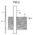
- FIG. 2is a magnified view of a part A depicted in FIG. 1 for explaining the characteristic feature of the laser light source apparatus according to the embodiment.
- FIG. 3is a perspective view of the laser light source apparatus according to the embodiment.
- FIG. 1is a schematic side view of an internal configuration of a laser light source apparatus 100 according to an embodiment of the present invention.
- FIG. 2is a magnified view of a part A depicted in FIG. 1 for explaining the characteristic feature of the laser light source apparatus 100 .
- FIG. 3is a perspective view of the laser light source apparatus 100 .
- the laser light source apparatus 100is used as a source of laser light in projection imaging devices such as televisions or display devices.
- the laser light source apparatus 100includes a laser light source 1 that emits laser light; a heat exchanger 2 that cools the laser light source 1 ; a base plate 3 on which the laser light source 1 and a driving circuit 3 a for driving the laser light source 1 are mounted; and a housing 4 that accommodates the laser light source 1 , the heat exchanger 2 , and the base plate 3 .
- the heat exchanger 2is attached to the laser light source 1 to cool the laser light source 1 .
- each laser light source 1is shown in FIG. 1 , in fact, three laser light sources 1 are arranged in the direction orthogonal to the plane of FIG. 1 to produce three primary colors, i.e., red (R), green (G), and blue (B).
- Each of the laser light sources 1includes the heat exchanger 2 .
- two heat exchangers 2are attached to the laser light source 1 that produces blue laser light.
- the laser light that is produced by the laser light sources 1is guided outside of the laser light source apparatus 100 by optical fibers (not shown).
- many intake ports 4 aare formed in a first side surface of the housing 4 .
- the intake ports 4 aare small ports having an elongated rectangular shape and are formed in substantially the entire first side surface of the housing 4 .
- Two exhaust ports 4 bare formed in a second side surface of the housing 4 .
- Air-cooling fans 5are provided inside the two exhaust ports 4 b , respectively. The air-cooling fans 5 circulate air that enters the housing 4 from the intake ports 4 a and discharges the air outside of the housing 4 from the exhaust ports 4 b as illustrated with arrows in FIG. 1 .
- Each of the heat exchangers 2includes at least one heat pipe 2 b extending from the laser light source 1 toward the exhaust ports 4 b and many cooling fins 2 a that are attached to the heat pipe 2 b .
- the heat pipes 2 b extending from the laser light sources 1are arranged side by side inside the housing 4 near the first side surface on which the intake ports 4 a are formed.
- the cooling fins 2 aare arranged orthogonal to the first side surface.
- a pitch D 1 between the cooling fins 2 ais equal to or less than a minimum width D 2 indicative of a length of a smaller side of the intake port 4 a shown in FIG. 3 .
- the operation of the laser light source apparatus 100will be described below.
- the intake airpasses through between the cooling fins 2 a .
- the cooling fins 2 aare arranged near the first side surface to cover the intake ports 4 a , the cooling fins 2 a can also serve as a filter. In this way, the cooling fins 2 a prevent dust that is larger than the pitch D 1 from coming inside the housing 4 .
- the laser light source apparatus 100includes the heat exchangers 2 and the air-cooling fans 5 .
- Each of the heat exchangers 2includes the cooling fins 2 a that cool the laser light sources 1 .
- the air-cooling fans 5which are attached to the second side surface of the housing 4 , discharge the air taken in from the intake ports 4 a to the exhaust ports 4 b to circulate the air inside the housing 4 .
- the cooling fins 2 aare arranged at a position opposed to the intake ports 4 a to be stacked up on each other at predetermined intervals.
- the pitch D 1 between the cooling fins 2 ais equal to or less than the minimum width D 2 of the intake port 4 a , which makes the cooling fins 2 a serve as the filter.
- the filterwhich is a necessary component in the conventional laser light source apparatus, is not required in the laser light source apparatus 100 according to the embodiment. In this manner, an amount of dust entering inside the housing 4 is reduced without increasing the number of types of the required materials and the number of the required components.
- the cooling fins 2 aare arranged orthogonal to the first side surface of the housing 4 , the air taken in from the intake port 4 a is circulated without being disturbed. Accordingly, the air passes through the housing 4 smoothly, which allows the cooling efficiency to be maintained.
- cooling fins 2 aare arranged in an air path through which the air taken in from the intake ports 4 a and discharged from the exhaust ports 4 b passes, a good cooling operation of the heat exchanger 2 is performed. Because the cooling fins 2 a are arranged inside the housing 4 to cover the intake ports 4 a , it is possible for the cooling fins 2 a to effectively act as a filter.
- the cooling fins 2 aare arranged orthogonal to the first side surface of the housing 4 in which the intake ports 4 a are formed; however, the configuration is not limited thereto.
- the cooling fins 2 acan be arranged to be inclined to the intake ports 4 a .
- a pitch of projections obtained when the cooling fins 2 a are projected on the first side surface from the direction parallel to the cooling fins 2 apreferably be equal to or less than the minimum width D 2 of the intake port 4 a .
- the laser light source apparatusaccommodates a laser light source, a driving circuit, or the like in a housing and includes a heat exchangers that cools the laser light source.
- the laser light source apparatusis suitable for use as a source of laser light in projection imaging devices such as televisions and display devices.
- air taken in from outside by an air-cooling fanpasses through between cooling fins. Therefore, the cooling fins also act as a filter.
- the filterwhich is a necessary component in the conventional laser light source apparatus, is not required; therefore, an amount of dust entering inside a housing is reduced without increasing the number of types of the required materials and the number of the required components.
Landscapes
- Physics & Mathematics (AREA)
- Electromagnetism (AREA)
- Engineering & Computer Science (AREA)
- Optics & Photonics (AREA)
- Signal Processing (AREA)
- Multimedia (AREA)
- Condensed Matter Physics & Semiconductors (AREA)
- General Physics & Mathematics (AREA)
- Plasma & Fusion (AREA)
- Lasers (AREA)
- Projection Apparatus (AREA)
- Cooling Or The Like Of Electrical Apparatus (AREA)
- Semiconductor Lasers (AREA)
Abstract
Description
Claims (4)
Applications Claiming Priority (2)
| Application Number | Priority Date | Filing Date | Title |
|---|---|---|---|
| JP2008170681AJP5153483B2 (en) | 2008-06-30 | 2008-06-30 | Laser light source device |
| JP2008-170681 | 2008-06-30 |
Publications (2)
| Publication Number | Publication Date |
|---|---|
| US20090323742A1 US20090323742A1 (en) | 2009-12-31 |
| US7965747B2true US7965747B2 (en) | 2011-06-21 |
Family
ID=41447357
Family Applications (1)
| Application Number | Title | Priority Date | Filing Date |
|---|---|---|---|
| US12/490,640Expired - Fee RelatedUS7965747B2 (en) | 2008-06-30 | 2009-06-24 | Laser light source apparatus |
Country Status (2)
| Country | Link |
|---|---|
| US (1) | US7965747B2 (en) |
| JP (1) | JP5153483B2 (en) |
Cited By (14)
| Publication number | Priority date | Publication date | Assignee | Title |
|---|---|---|---|---|
| US8997362B2 (en) | 2012-07-17 | 2015-04-07 | Faro Technologies, Inc. | Portable articulated arm coordinate measuring machine with optical communications bus |
| US9009000B2 (en) | 2010-01-20 | 2015-04-14 | Faro Technologies, Inc. | Method for evaluating mounting stability of articulated arm coordinate measurement machine using inclinometers |
| US9163922B2 (en) | 2010-01-20 | 2015-10-20 | Faro Technologies, Inc. | Coordinate measurement machine with distance meter and camera to determine dimensions within camera images |
| US9168654B2 (en) | 2010-11-16 | 2015-10-27 | Faro Technologies, Inc. | Coordinate measuring machines with dual layer arm |
| USRE45854E1 (en) | 2006-07-03 | 2016-01-19 | Faro Technologies, Inc. | Method and an apparatus for capturing three-dimensional data of an area of space |
| US9372265B2 (en) | 2012-10-05 | 2016-06-21 | Faro Technologies, Inc. | Intermediate two-dimensional scanning with a three-dimensional scanner to speed registration |
| US9417056B2 (en) | 2012-01-25 | 2016-08-16 | Faro Technologies, Inc. | Device for optically scanning and measuring an environment |
| US9513107B2 (en) | 2012-10-05 | 2016-12-06 | Faro Technologies, Inc. | Registration calculation between three-dimensional (3D) scans based on two-dimensional (2D) scan data from a 3D scanner |
| US9551575B2 (en) | 2009-03-25 | 2017-01-24 | Faro Technologies, Inc. | Laser scanner having a multi-color light source and real-time color receiver |
| US9607239B2 (en) | 2010-01-20 | 2017-03-28 | Faro Technologies, Inc. | Articulated arm coordinate measurement machine having a 2D camera and method of obtaining 3D representations |
| US9628775B2 (en) | 2010-01-20 | 2017-04-18 | Faro Technologies, Inc. | Articulated arm coordinate measurement machine having a 2D camera and method of obtaining 3D representations |
| US10067231B2 (en) | 2012-10-05 | 2018-09-04 | Faro Technologies, Inc. | Registration calculation of three-dimensional scanner data performed between scans based on measurements by two-dimensional scanner |
| US10175037B2 (en) | 2015-12-27 | 2019-01-08 | Faro Technologies, Inc. | 3-D measuring device with battery pack |
| US10281259B2 (en) | 2010-01-20 | 2019-05-07 | Faro Technologies, Inc. | Articulated arm coordinate measurement machine that uses a 2D camera to determine 3D coordinates of smoothly continuous edge features |
Families Citing this family (23)
| Publication number | Priority date | Publication date | Assignee | Title |
|---|---|---|---|---|
| DE102009010465B3 (en) | 2009-02-13 | 2010-05-27 | Faro Technologies, Inc., Lake Mary | laser scanner |
| DE102009015920B4 (en) | 2009-03-25 | 2014-11-20 | Faro Technologies, Inc. | Device for optically scanning and measuring an environment |
| DE102009035337A1 (en) | 2009-07-22 | 2011-01-27 | Faro Technologies, Inc., Lake Mary | Method for optically scanning and measuring an object |
| DE102009035336B3 (en) | 2009-07-22 | 2010-11-18 | Faro Technologies, Inc., Lake Mary | Device for optical scanning and measuring of environment, has optical measuring device for collection of ways as ensemble between different centers returning from laser scanner |
| DE102009055989B4 (en) | 2009-11-20 | 2017-02-16 | Faro Technologies, Inc. | Device for optically scanning and measuring an environment |
| US9210288B2 (en) | 2009-11-20 | 2015-12-08 | Faro Technologies, Inc. | Three-dimensional scanner with dichroic beam splitters to capture a variety of signals |
| DE102009055988B3 (en) | 2009-11-20 | 2011-03-17 | Faro Technologies, Inc., Lake Mary | Device, particularly laser scanner, for optical scanning and measuring surrounding area, has light transmitter that transmits transmission light ray by rotor mirror |
| DE102009057101A1 (en) | 2009-11-20 | 2011-05-26 | Faro Technologies, Inc., Lake Mary | Device for optically scanning and measuring an environment |
| US9529083B2 (en) | 2009-11-20 | 2016-12-27 | Faro Technologies, Inc. | Three-dimensional scanner with enhanced spectroscopic energy detector |
| US9113023B2 (en) | 2009-11-20 | 2015-08-18 | Faro Technologies, Inc. | Three-dimensional scanner with spectroscopic energy detector |
| JP5511420B2 (en)* | 2010-02-05 | 2014-06-04 | 三菱電機株式会社 | Laser light source device and projector device |
| DE102010020925B4 (en) | 2010-05-10 | 2014-02-27 | Faro Technologies, Inc. | Method for optically scanning and measuring an environment |
| DE102010032723B3 (en)* | 2010-07-26 | 2011-11-24 | Faro Technologies, Inc. | Device for optically scanning and measuring an environment |
| DE102010032726B3 (en)* | 2010-07-26 | 2011-11-24 | Faro Technologies, Inc. | Device for optically scanning and measuring an environment |
| DE102010032724A1 (en)* | 2010-07-26 | 2012-01-26 | Faro Technologies, Inc. | Device for optically scanning and measuring an environment |
| DE102010032725B4 (en) | 2010-07-26 | 2012-04-26 | Faro Technologies, Inc. | Device for optically scanning and measuring an environment |
| DE102010033561B3 (en) | 2010-07-29 | 2011-12-15 | Faro Technologies, Inc. | Device for optically scanning and measuring an environment |
| DE102012107544B3 (en) | 2012-08-17 | 2013-05-23 | Faro Technologies, Inc. | Optical scanning device i.e. laser scanner, for evaluating environment, has planetary gears driven by motor over vertical motor shaft and rotating measuring head relative to foot, where motor shaft is arranged coaxial to vertical axle |
| JP5775062B2 (en) | 2012-12-27 | 2015-09-09 | レノボ・シンガポール・プライベート・リミテッド | Electronic equipment and electronic equipment system |
| KR101397449B1 (en)* | 2013-12-20 | 2014-06-27 | 국방과학연구소 | Heat dissipation apparatus for laser and laser device having the same |
| EP3141951B1 (en)* | 2014-04-08 | 2018-10-17 | Sony Corporation | Light source device and image display device |
| US11367996B2 (en)* | 2020-06-11 | 2022-06-21 | The Boeing Company | Control system for regulating temperature for laser diodes |
| CN119093139B (en)* | 2024-11-08 | 2025-02-07 | 厦门纽立特电子科技有限公司 | Lath amplifier with three-dimensional graphene structure for heat dissipation |
Citations (13)
| Publication number | Priority date | Publication date | Assignee | Title |
|---|---|---|---|---|
| JPS6421983A (en)* | 1987-07-16 | 1989-01-25 | Komatsu Mfg Co Ltd | Gas laser apparatus |
| JPH0225082A (en)* | 1988-07-14 | 1990-01-26 | Kawasaki Steel Corp | Gas laser device |
| JPH0581821B2 (en) | 1988-06-30 | 1993-11-16 | Sanyo Electric Co | |
| US5481556A (en)* | 1993-10-01 | 1996-01-02 | S.L.T. Japan Co., Ltd. | Laser oscillation apparatus with cooling fan and cooling fins |
| US5550853A (en)* | 1994-12-21 | 1996-08-27 | Laser Physics, Inc. | Integral laser head and power supply |
| US5901167A (en)* | 1997-04-30 | 1999-05-04 | Universal Laser Systems, Inc. | Air cooled gas laser |
| US20020018497A1 (en)* | 2000-08-01 | 2002-02-14 | Nidek Co., Ltd. | Laser treatment apparatus |
| US20020167978A1 (en)* | 2001-05-14 | 2002-11-14 | Dainippon Screen Mfg. Co., Ltd. | Device supporting apparatus |
| US20030021312A1 (en)* | 2001-07-25 | 2003-01-30 | Gruzdev Valentin A. | Portable laser device |
| US20050013328A1 (en)* | 1998-09-08 | 2005-01-20 | Heinrich Jurgensen | Laser radiation source |
| US20050123011A1 (en)* | 2003-12-04 | 2005-06-09 | Yefim Sukhman | Method and apparatus for cooling a laser |
| JP2007115020A (en) | 2005-10-20 | 2007-05-10 | Toshiba Corp | Information processing apparatus having dustproof filter |
| US7415051B1 (en)* | 2003-06-16 | 2008-08-19 | Universal Laser Systems, Inc. | Air cooler laser apparatus and method |
Family Cites Families (6)
| Publication number | Priority date | Publication date | Assignee | Title |
|---|---|---|---|---|
| US6109767A (en)* | 1996-03-29 | 2000-08-29 | Minnesota Mining And Manufacturing Company | Honeycomb light and heat trap for projector |
| JPH10233590A (en)* | 1997-02-20 | 1998-09-02 | Nec Corp | Cooling structure for small-sized electronic apparatus |
| JP2004334082A (en)* | 2003-05-12 | 2004-11-25 | Plus Vision Corp | Illumination optical system using semiconductor laser device as light source and projector utilizing the same |
| JP2005321525A (en)* | 2004-05-07 | 2005-11-17 | Seiko Epson Corp | projector |
| WO2007040089A1 (en)* | 2005-09-30 | 2007-04-12 | Matsushita Electric Industrial Co., Ltd. | Laser projection device |
| JP2008145486A (en)* | 2006-12-06 | 2008-06-26 | Seiko Epson Corp | projector |
- 2008
- 2008-06-30JPJP2008170681Apatent/JP5153483B2/ennot_activeExpired - Fee Related
- 2009
- 2009-06-24USUS12/490,640patent/US7965747B2/ennot_activeExpired - Fee Related
Patent Citations (13)
| Publication number | Priority date | Publication date | Assignee | Title |
|---|---|---|---|---|
| JPS6421983A (en)* | 1987-07-16 | 1989-01-25 | Komatsu Mfg Co Ltd | Gas laser apparatus |
| JPH0581821B2 (en) | 1988-06-30 | 1993-11-16 | Sanyo Electric Co | |
| JPH0225082A (en)* | 1988-07-14 | 1990-01-26 | Kawasaki Steel Corp | Gas laser device |
| US5481556A (en)* | 1993-10-01 | 1996-01-02 | S.L.T. Japan Co., Ltd. | Laser oscillation apparatus with cooling fan and cooling fins |
| US5550853A (en)* | 1994-12-21 | 1996-08-27 | Laser Physics, Inc. | Integral laser head and power supply |
| US5901167A (en)* | 1997-04-30 | 1999-05-04 | Universal Laser Systems, Inc. | Air cooled gas laser |
| US20050013328A1 (en)* | 1998-09-08 | 2005-01-20 | Heinrich Jurgensen | Laser radiation source |
| US20020018497A1 (en)* | 2000-08-01 | 2002-02-14 | Nidek Co., Ltd. | Laser treatment apparatus |
| US20020167978A1 (en)* | 2001-05-14 | 2002-11-14 | Dainippon Screen Mfg. Co., Ltd. | Device supporting apparatus |
| US20030021312A1 (en)* | 2001-07-25 | 2003-01-30 | Gruzdev Valentin A. | Portable laser device |
| US7415051B1 (en)* | 2003-06-16 | 2008-08-19 | Universal Laser Systems, Inc. | Air cooler laser apparatus and method |
| US20050123011A1 (en)* | 2003-12-04 | 2005-06-09 | Yefim Sukhman | Method and apparatus for cooling a laser |
| JP2007115020A (en) | 2005-10-20 | 2007-05-10 | Toshiba Corp | Information processing apparatus having dustproof filter |
Cited By (23)
| Publication number | Priority date | Publication date | Assignee | Title |
|---|---|---|---|---|
| USRE45854E1 (en) | 2006-07-03 | 2016-01-19 | Faro Technologies, Inc. | Method and an apparatus for capturing three-dimensional data of an area of space |
| US9551575B2 (en) | 2009-03-25 | 2017-01-24 | Faro Technologies, Inc. | Laser scanner having a multi-color light source and real-time color receiver |
| US9628775B2 (en) | 2010-01-20 | 2017-04-18 | Faro Technologies, Inc. | Articulated arm coordinate measurement machine having a 2D camera and method of obtaining 3D representations |
| US9009000B2 (en) | 2010-01-20 | 2015-04-14 | Faro Technologies, Inc. | Method for evaluating mounting stability of articulated arm coordinate measurement machine using inclinometers |
| US9163922B2 (en) | 2010-01-20 | 2015-10-20 | Faro Technologies, Inc. | Coordinate measurement machine with distance meter and camera to determine dimensions within camera images |
| US10281259B2 (en) | 2010-01-20 | 2019-05-07 | Faro Technologies, Inc. | Articulated arm coordinate measurement machine that uses a 2D camera to determine 3D coordinates of smoothly continuous edge features |
| US10060722B2 (en) | 2010-01-20 | 2018-08-28 | Faro Technologies, Inc. | Articulated arm coordinate measurement machine having a 2D camera and method of obtaining 3D representations |
| US9607239B2 (en) | 2010-01-20 | 2017-03-28 | Faro Technologies, Inc. | Articulated arm coordinate measurement machine having a 2D camera and method of obtaining 3D representations |
| US9168654B2 (en) | 2010-11-16 | 2015-10-27 | Faro Technologies, Inc. | Coordinate measuring machines with dual layer arm |
| US9417056B2 (en) | 2012-01-25 | 2016-08-16 | Faro Technologies, Inc. | Device for optically scanning and measuring an environment |
| US8997362B2 (en) | 2012-07-17 | 2015-04-07 | Faro Technologies, Inc. | Portable articulated arm coordinate measuring machine with optical communications bus |
| US9618620B2 (en) | 2012-10-05 | 2017-04-11 | Faro Technologies, Inc. | Using depth-camera images to speed registration of three-dimensional scans |
| US9739886B2 (en) | 2012-10-05 | 2017-08-22 | Faro Technologies, Inc. | Using a two-dimensional scanner to speed registration of three-dimensional scan data |
| US9746559B2 (en) | 2012-10-05 | 2017-08-29 | Faro Technologies, Inc. | Using two-dimensional camera images to speed registration of three-dimensional scans |
| US9513107B2 (en) | 2012-10-05 | 2016-12-06 | Faro Technologies, Inc. | Registration calculation between three-dimensional (3D) scans based on two-dimensional (2D) scan data from a 3D scanner |
| US10067231B2 (en) | 2012-10-05 | 2018-09-04 | Faro Technologies, Inc. | Registration calculation of three-dimensional scanner data performed between scans based on measurements by two-dimensional scanner |
| US10203413B2 (en) | 2012-10-05 | 2019-02-12 | Faro Technologies, Inc. | Using a two-dimensional scanner to speed registration of three-dimensional scan data |
| US9372265B2 (en) | 2012-10-05 | 2016-06-21 | Faro Technologies, Inc. | Intermediate two-dimensional scanning with a three-dimensional scanner to speed registration |
| US10739458B2 (en) | 2012-10-05 | 2020-08-11 | Faro Technologies, Inc. | Using two-dimensional camera images to speed registration of three-dimensional scans |
| US11035955B2 (en) | 2012-10-05 | 2021-06-15 | Faro Technologies, Inc. | Registration calculation of three-dimensional scanner data performed between scans based on measurements by two-dimensional scanner |
| US11112501B2 (en) | 2012-10-05 | 2021-09-07 | Faro Technologies, Inc. | Using a two-dimensional scanner to speed registration of three-dimensional scan data |
| US11815600B2 (en) | 2012-10-05 | 2023-11-14 | Faro Technologies, Inc. | Using a two-dimensional scanner to speed registration of three-dimensional scan data |
| US10175037B2 (en) | 2015-12-27 | 2019-01-08 | Faro Technologies, Inc. | 3-D measuring device with battery pack |
Also Published As
| Publication number | Publication date |
|---|---|
| US20090323742A1 (en) | 2009-12-31 |
| JP2010008905A (en) | 2010-01-14 |
| JP5153483B2 (en) | 2013-02-27 |
Similar Documents
| Publication | Publication Date | Title |
|---|---|---|
| US7965747B2 (en) | Laser light source apparatus | |
| US8246171B2 (en) | Cooling device and projector using the same | |
| US8087788B2 (en) | Projector with cooling configuration | |
| US8007114B2 (en) | Small-sized projector with high heat dissipating efficiency | |
| US8052282B2 (en) | Heat dissipation system and electronic device utilizing the same | |
| CN103499909B (en) | Projection device | |
| JP7036915B2 (en) | Electronic devices and projectors | |
| CN101090627A (en) | Cooling unit and projector | |
| US8403497B2 (en) | Projector | |
| TWI447509B (en) | Heat dissipation device of porjector optical mechanical | |
| US8345214B2 (en) | Cooling device of electronic apparatus and liquid crystal projector equipped with same including ducts communicating with respective openings | |
| US7543962B2 (en) | Projection-type image display device | |
| US20100118280A1 (en) | Light-source module and projector having same | |
| US8690346B2 (en) | Projection display apparatus including wind outlets for cooling optical part | |
| US20090051885A1 (en) | Light shield used in projector | |
| US6808296B2 (en) | Cooling apparatus for optical engine assembly | |
| CN112424688B (en) | Electronic equipment and projectors | |
| US9488900B2 (en) | Projection apparatus including light sources and heat radiating members | |
| JP2020020824A (en) | Projection display device having intake air temperature sensor and cooling device | |
| CN222232861U (en) | A direct projection open light machine with high efficiency heat dissipation and LCD projector | |
| JP2024106811A (en) | projector | |
| JP2010117589A (en) | Louver, and projection type video display device having same | |
| JP2018128616A (en) | Cooling device and picture display unit using the same |
Legal Events
| Date | Code | Title | Description |
|---|---|---|---|
| AS | Assignment | Owner name:MITSUBISHI ELECTRIC CORPORATION, JAPAN Free format text:ASSIGNMENT OF ASSIGNORS INTEREST;ASSIGNOR:KUMANO, KOJI;REEL/FRAME:022887/0672 Effective date:20090528 | |
| STCF | Information on status: patent grant | Free format text:PATENTED CASE | |
| FEPP | Fee payment procedure | Free format text:PAYOR NUMBER ASSIGNED (ORIGINAL EVENT CODE: ASPN); ENTITY STATUS OF PATENT OWNER: LARGE ENTITY | |
| FPAY | Fee payment | Year of fee payment:4 | |
| AS | Assignment | Owner name:SEIKO EPSON CORPORATION, JAPAN Free format text:ASSIGNMENT OF ASSIGNORS INTEREST;ASSIGNOR:MITSUBISHI ELECTRIC CORPORATION;REEL/FRAME:037168/0481 Effective date:20151109 | |
| MAFP | Maintenance fee payment | Free format text:PAYMENT OF MAINTENANCE FEE, 8TH YEAR, LARGE ENTITY (ORIGINAL EVENT CODE: M1552); ENTITY STATUS OF PATENT OWNER: LARGE ENTITY Year of fee payment:8 | |
| FEPP | Fee payment procedure | Free format text:MAINTENANCE FEE REMINDER MAILED (ORIGINAL EVENT CODE: REM.); ENTITY STATUS OF PATENT OWNER: LARGE ENTITY | |
| LAPS | Lapse for failure to pay maintenance fees | Free format text:PATENT EXPIRED FOR FAILURE TO PAY MAINTENANCE FEES (ORIGINAL EVENT CODE: EXP.); ENTITY STATUS OF PATENT OWNER: LARGE ENTITY | |
| STCH | Information on status: patent discontinuation | Free format text:PATENT EXPIRED DUE TO NONPAYMENT OF MAINTENANCE FEES UNDER 37 CFR 1.362 | |
| FP | Lapsed due to failure to pay maintenance fee | Effective date:20230621 |