US7965188B2 - Radio frequency animal tracking system - Google Patents
Radio frequency animal tracking systemDownload PDFInfo
- Publication number
- US7965188B2 US7965188B2US12/608,206US60820609AUS7965188B2US 7965188 B2US7965188 B2US 7965188B2US 60820609 AUS60820609 AUS 60820609AUS 7965188 B2US7965188 B2US 7965188B2
- Authority
- US
- United States
- Prior art keywords
- tag
- animal
- base station
- identification
- rfid
- Prior art date
- Legal status (The legal status is an assumption and is not a legal conclusion. Google has not performed a legal analysis and makes no representation as to the accuracy of the status listed.)
- Expired - Fee Related
Links
Images


Classifications
- A—HUMAN NECESSITIES
- A01—AGRICULTURE; FORESTRY; ANIMAL HUSBANDRY; HUNTING; TRAPPING; FISHING
- A01K—ANIMAL HUSBANDRY; AVICULTURE; APICULTURE; PISCICULTURE; FISHING; REARING OR BREEDING ANIMALS, NOT OTHERWISE PROVIDED FOR; NEW BREEDS OF ANIMALS
- A01K11/00—Marking of animals
- A01K11/001—Ear-tags
- A01K11/004—Ear-tags with electronic identification means, e.g. transponders
- A—HUMAN NECESSITIES
- A01—AGRICULTURE; FORESTRY; ANIMAL HUSBANDRY; HUNTING; TRAPPING; FISHING
- A01K—ANIMAL HUSBANDRY; AVICULTURE; APICULTURE; PISCICULTURE; FISHING; REARING OR BREEDING ANIMALS, NOT OTHERWISE PROVIDED FOR; NEW BREEDS OF ANIMALS
- A01K11/00—Marking of animals
- A01K11/006—Automatic identification systems for animals, e.g. electronic devices, transponders for animals
- G—PHYSICS
- G06—COMPUTING OR CALCULATING; COUNTING
- G06K—GRAPHICAL DATA READING; PRESENTATION OF DATA; RECORD CARRIERS; HANDLING RECORD CARRIERS
- G06K19/00—Record carriers for use with machines and with at least a part designed to carry digital markings
- G06K19/06—Record carriers for use with machines and with at least a part designed to carry digital markings characterised by the kind of the digital marking, e.g. shape, nature, code
- G06K19/067—Record carriers with conductive marks, printed circuits or semiconductor circuit elements, e.g. credit or identity cards also with resonating or responding marks without active components
- G06K19/07—Record carriers with conductive marks, printed circuits or semiconductor circuit elements, e.g. credit or identity cards also with resonating or responding marks without active components with integrated circuit chips
- G06K19/077—Constructional details, e.g. mounting of circuits in the carrier
- G06K19/07749—Constructional details, e.g. mounting of circuits in the carrier the record carrier being capable of non-contact communication, e.g. constructional details of the antenna of a non-contact smart card
- G06K19/07758—Constructional details, e.g. mounting of circuits in the carrier the record carrier being capable of non-contact communication, e.g. constructional details of the antenna of a non-contact smart card arrangements for adhering the record carrier to further objects or living beings, functioning as an identification tag
- G—PHYSICS
- G06—COMPUTING OR CALCULATING; COUNTING
- G06K—GRAPHICAL DATA READING; PRESENTATION OF DATA; RECORD CARRIERS; HANDLING RECORD CARRIERS
- G06K19/00—Record carriers for use with machines and with at least a part designed to carry digital markings
- G06K19/06—Record carriers for use with machines and with at least a part designed to carry digital markings characterised by the kind of the digital marking, e.g. shape, nature, code
- G06K19/067—Record carriers with conductive marks, printed circuits or semiconductor circuit elements, e.g. credit or identity cards also with resonating or responding marks without active components
- G06K19/07—Record carriers with conductive marks, printed circuits or semiconductor circuit elements, e.g. credit or identity cards also with resonating or responding marks without active components with integrated circuit chips
- G06K19/077—Constructional details, e.g. mounting of circuits in the carrier
- G06K19/07749—Constructional details, e.g. mounting of circuits in the carrier the record carrier being capable of non-contact communication, e.g. constructional details of the antenna of a non-contact smart card
- G06K19/07766—Constructional details, e.g. mounting of circuits in the carrier the record carrier being capable of non-contact communication, e.g. constructional details of the antenna of a non-contact smart card comprising at least a second communication arrangement in addition to a first non-contact communication arrangement
- G06K19/07767—Constructional details, e.g. mounting of circuits in the carrier the record carrier being capable of non-contact communication, e.g. constructional details of the antenna of a non-contact smart card comprising at least a second communication arrangement in addition to a first non-contact communication arrangement the first and second communication means being two different antennas types, e.g. dipole and coil type, or two antennas of the same kind but operating at different frequencies
- G—PHYSICS
- G08—SIGNALLING
- G08B—SIGNALLING OR CALLING SYSTEMS; ORDER TELEGRAPHS; ALARM SYSTEMS
- G08B29/00—Checking or monitoring of signalling or alarm systems; Prevention or correction of operating errors, e.g. preventing unauthorised operation
- G08B29/16—Security signalling or alarm systems, e.g. redundant systems
Definitions
- the inventionrelates to a radio frequency identification system and more particularly to a radio frequency identification system for tracking animals.
- RFID systemsare well known. RFID systems are either active systems wherein the transponder includes its own power source or passive systems wherein the transponder receives its power from a base station. Since passive RFID systems do not require their own power source they are generally smaller, lighter, and cheaper to manufacture than active RFID systems. Consequently, passive systems are more commonly employed in RFID systems for the purpose of tracking as compared to active systems.
- Passive RFID systemsare generally either inductively coupled RFID systems or capacitively coupled RFID systems.
- the present disclosureis applicable to both types of passive systems; however, the present description focuses on inductively coupled systems because they are presently more common due to the fact that they have a greater effective range than capacitively coupled systems.
- Passive inductively coupled RFID systemstypically include a transponder that has a microprocessor chip encircled by, and electrically connected to, a metal coil that functions as an antenna as well as an inductance element.
- the metal coilreceives radio frequencies from a base station and generates an electrical current that powers the microprocessor, which is programmed to retrieve stored data such as an identification number and transmit the data back to the base station.
- Standard transmission frequencieshave been established for RFID tags based upon their field of use. For example, 13.56 MHz is a standard radio frequency used for tracking manufactured goods, whereas 400 kHz is a standard radio frequency used for tracking salmon as they travel upstream to spawn.
- the standard radio frequency used for identification tags for livestock and other animalsis currently 134.2 kHz. This relatively low radio frequency is advantageous because it can effectively penetrate water-containing objects such as animals. On the other hand, the frequency does not have a high transmission rate. Therefore, current RFID systems do not work well where fast data transmission is required, such as in certain real time tracking applications of fast moving objects.
- identification codesalso commonly referred to as identification codes
- current identification tags manufactured according to the above outlined processesare typically not customizable by the end users and generally include only a stored identification number.
- the datamust, for example, be stored on a separate computer and electronically associated with an identification number. This limitation may necessitate carrying a computer out in the field, which can be inconvenient and impractical.
- the new livestock handlermay not have access to the data that is associated with the identification number because the data is not transferred to the new handler. Instead, the data must be stored on a network or otherwise deliberately made available to the new handler.
- current identification tagsare not generally adapted to be used to measure physical parameters of the animals such as the animal's internal temperature, which can be helpful in determining if the animal is ill. Accordingly, it is desirable to developed an RFID system where the livestock handler can customize the identification tag; where data in addition to an identification number can be stored in the tag itself, where the livestock handler can use the tag to track physical parameters of the livestock in real time; and/or where the system remains compatible with current base stations.
- the inventionis directed to an improved RFID system, methods of using the system, and methods of making the system.
- the systemincludes a transponder that can communicate over at least two different frequencies. Such an embodiment can provide improved real time performance of the transponder without losing backwards compatibility.
- the systemincludes an improved apparatus and method that allows the end user to customize and program identification tags.
- the inventionincludes the tags including user provided data in print and/or in electronic form.
- the systemcan provide an ear tag for use on livestock that exhibits advantageous performance in the field, shelter, and/or plant.
- a radio frequency identification (RFID) tagfor identification of animals includes a first antenna and a transponder coupled to the antenna.
- the transponderincludes a first transmission unit, first memory and first power circuitry.
- the first power circuitryis configured to receive a current induced in the first antenna, and to power the first transmission unit and first memory.
- the first transmission unitis configured to retrieve data stored in the first memory and to transmit at least a portion of the data via the first antenna on a first carrier frequency and on a second carrier frequency.
- a method of manufacturing a radio frequency identification (RFID) tagfor identification of animals includes providing a substrate, and disposing a first coil upon the substrate. A first integrated circuit is coupled to the first coil. A first material is formed atop the first coil and first integrated circuit. A second material is formed over the first material.
- RFIDradio frequency identification
- a method of collision prevention for radio frequency identification (RFID) tags for identification of animalsincludes assigning each of a plurality of RFID tags a delay value.
- Each RFID tagis configured to receive a query from a base station, and to respond thereto by waiting for a duration of time corresponding to the delay value. Then, a response transmission is provided.
- the response transmissionincludes a unique identification number identifying an animal associated with the tag.
- a method of providing identification of an animalincludes receiving a query from a base station with a radio frequency identification (RFID) tag in an animal.
- the queryis responded to with a first transmission on a first carrier frequency and a second transmission on a second carrier frequency.
- RFIDradio frequency identification
- a method of identifying an animal to a base station with a radio frequency identification (RFID) tagincludes providing the base station with a smallest identification number assigned to any of a plurality of RFID tags associated with a plurality of animals.
- a query from the base stationis received with an RFID tag in the animal.
- the RFID tagbeing is a unique identification number.
- the received queryis responded to with a reply transmission including an abbreviated identification number, which is the difference between the unique identifying number and the smallest identification number.
- a system for identifying animals with radio frequency identification (RFID) tagsincludes a first base station configured to operate at a first carrier frequency.
- the systemalso includes a second base station configured to operate at a second carrier frequency.
- the systemfurther includes a plurality of RFID tags each associated with one of a plurality of animals.
- Each RFID tagis configured to respond to a transmission on a first carrier frequency with a response transmission on the first carrier frequency and a response transmission on a second carrier frequency. At least one of the response transmissions includes a unique identification number.
- FIG. 1is a diagrammatic illustration of a known RFID system commonly used to track livestock.
- FIG. 2is a diagrammatic illustration of an RFID system according to the principles of the present invention.
- FIG. 3is a diagrammatic illustration of a portion of the manufacturing of the identification tag of the RFID system of FIG. 2 .
- FIG. 4is a diagrammatic illustration of a top view of a strip of identification tags of FIG. 3 .
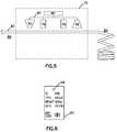
- FIG. 5is a diagrammatic illustration of the finishing process of the identification tag of the RFID system of FIG. 2 .
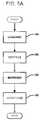
- FIG. 5Ais a flowchart showing an operational flow for customizing and finishing a strip of tags in accordance with the principles of the present disclosure.
- FIG. 6is a front elevation view of an identification tag according to the principles of the present invention.
- FIG. 7is a schematic diagram of an alternative embodiment of a substrate on which identification tags according to the present invention may be formed.
- FIG. 8is a schematic diagram of an encoding device for use with the identification tags of FIG. 7 .
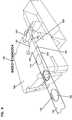
- FIG. 9is a schematic diagram of a forming device for forming identification tags upon the substrate of FIG. 7 .
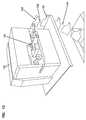
- FIG. 10is a perspective view of a printing device for printing onto the identification tags of FIG. 7 .
- FIG. 11is a perspective view of a second embodiment of a printing device for printing onto the identification tags of FIG. 7 .
- FIG. 12is a representation of communication between the printing device of FIG. 11 and a remote database.
- FIG. 13is a schematic diagram of animals tagged with an identification tag moving through a chute adjacent a transceiver.
- FIG. 14is a depiction of a transport vehicle unloading animals for entry into a facility.
- FIG. 15is a depiction of an exemplary method of reducing interference between RFID tags.
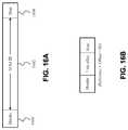
- FIG. 16Adepicts an exemplary embodiment of a data frame transmitted from an RFID tag to a base station.
- FIG. 16Bdepicts an exemplary embodiment of a data frame transmitted from an RFID tag to a base station.
- FIG. 17Ais a profile depiction of an exemplary embodiment of a button-style RFID tag.
- FIG. 17Bis a bottom-view of the button-style RFID tag depicted in FIG. 17A .
- FIG. 18is a schematic block diagram of an animal tag in accordance with the principles of the present disclosure.
- animalrefers to macroscopic animals including vertebrates. Animals include domesticated animals, such as livestock and companion animals, and wild animals, such as game animals or fish. Livestock include animals such as swine (pig), piglet, sheep, lamb, goat, bovine (e.g., cow), fish and (e.g., salmon), birds (e.g., chickens, ducks, and geese). This list of animals is intended to be illustrative only, and should not limit the scope of any of the following disclosure related to the present invention. As used herein, the term “track” refers to the identification, location, recording, and monitoring of animals or other objects of interest, for whatever purpose or reason. This definition is illustrative of uses of the present invention and is not intended to limit the scope of any of the following disclosure related to the present invention.
- An identification tag for an animalincluding a first circuit including a memory subunit, a power subunit, and a first transmit subunit, the subunits electrically connected to each other.
- the tagalso includes a second circuit including a second transmit subunit, the second circuit electrically connected to the first circuit, and an antenna connected to the first circuit.
- the power subunit of the first circuitis configured to generate an electrical current when a radio signal is received by the antenna, and delivers this current to the first transmit subunit.
- the first transmit subunitis configured to transmit a first signal at a first frequency when it receives electrical current from the power subunit, the first signal encoding at least a first portion of any data within the memory subunit.
- the second circuitis configured to transmit a second signal at a second frequency when it when it receives electrical current from the power subunit, the second signal encoding at least a second portion of any data within the memory subunit.
- a method of making an identification tag for an animalincluding providing a producer of animals, at least one animal, an animal identification tag with a data transponder and a memory storage, and a tag printer located adjacent a space for confining the at least one animal. At least one registration code is acquired to be assigned to the at least one animal. The at least one registration code is input to the tag printer. The animal is positioned in the confined space adjacent the tag printer. The animal identification tag is positioned within the tag printer. The registration code is printed on an exterior of the animal identification tag. The registration code is written into the memory storage of the animal identification tag. The animal identification tag is removed from the machine and attached to the animal.
- An animal identification tagincludes a flexible substrate including upper and lower portions.
- a substantially rigid transponder mountis positioned between the upper and lower portions.
- a transponderis mounted to the transponder mount.
- the transponderincludes a data memory storage, an antenna, power circuitry and transmission circuitry.
- the power circuitryis configured to generate electrical current when a first radio signal at a first frequency is received by the antenna.
- the transmission circuitryis configured to transmit at least a portion of any data within the data memory storage at a second frequency, and to transmit at least a portion of any data within the data memory storage at a second frequency when electrical current is received from the power circuitry.
- a mounting openingextends through the upper and lower portions and a mounting opening reinforcement mounted between the upper and lower bodies adjacent the mounting opening.
- a device for making animal identification tagsincluding a housing with a path along which an animal identification tag may be positioned.
- a data writing apparatusis located within the housing adjacent the path and positioned to write digital information to a data storage of the animal identification tag.
- a printing deviceis located within the housing adjacent the path and positioned to print information on an exterior of the animal identification tag.
- An optical scanneris located within the housing and positioned adjacent the path to optically scan the printed information on the exterior of the animal identification tag.
- a radio frequency generator and receiveris located within the housing and positioned adjacent the path to query the digital information written into the data storage of the animal identification tag.
- a method of tracking livestockincludes registering an identification code with a central database, wherein registering includes associating the identification code with a user name.
- a passive radio frequency identification tagis provided. The identification code is written to the passive radio frequency identification tag. Subsequently additional data is written to the passive radio frequency identification tag.
- a method of tracking livestockincluding registering an identification code with a central database, wherein registering includes associating the identification code with a user name.
- a passive radio frequency identification tagis provided. The identification code is written to the passive radio frequency identification tag at a physical location where an animal to be tracked is located.
- a method of tracking livestockincluding registering an identification code with a central database, wherein registering includes associating the identification code with a user name.
- a passive radio frequency identification tagis provided. The identification code is written to the passive radio frequency identification tag. The passive radio frequency identification tag is queried using a first frequency and transmits a response at a second frequency.
- a radio frequency identification tagincludes a flexible substrate and a transponder position within the flexible substrate.
- the transponderincludes a passive inductance radio frequency device positioned within a substantially rigid housing.
- the present inventionincludes an animal, the animal including coupled to an appendage (e.g., an ear) a tag according to the present invention.
- an appendagee.g., an ear
- the conventional RFID system 10includes a base station 12 , also commonly referred to as a reader, and a transponder 14 , also commonly referred to as an identification tag.
- the transponder 14 and base station 12are configured to be used to track livestock.
- the base station 12 and transponder 14are configured to transmit and receive radio waves at the current industry standard for RFID livestock tracking, which is 134.2 kHz.
- the base stationincludes a transceiver 16 that emits a radio signal 18 , which may be received by the transponder 14 .
- the transponder 14includes a wire loop antenna 20 constructed of metal.
- the wire loop antenna 20receives the signal 18 and functions as an inductor to generate an electric current from the signal 18 .
- the generated electric currentpowers the semiconductor chip 22 , which is programmed to retrieve a stored identification number/code and convert the number into a signal 24 that is transmitted back to the transceiver 16 in the base station 12 .
- the transponder 14includes a substantially rigid housing 26 that protects the wire loop antenna 20 from bending which would likely otherwise impede or destroy the wire loop antenna's 20 ability to perform.
- the housingmay be made in the form of a plastic disk and include a hole that is sized to receive a fastener for attaching the housing 26 directly to the ear of an animal.
- a conventional RFID system 10 like the one described abovemay perform poorly in identifying animals if they move rapidly past a point in space, such as a gate at a cattle ranch.
- the conventional RFID system 10may perform poorly due to the length of time between the sending of the signal 18 from the base station 12 and the receipt of the return signal 24 at the base station 12 . During this time the animal can move, thereby making it difficult to associate the received number with the correct animal. During this time the animal may even move out of the communication range of the base station 12 .
- This task of identifying animals in a dynamic environmentis especially difficult when there are other animals of similar appearance nearby.
- Increasing the overall frequency of transmissionwhich can increase data transmission rates, presents one way to decrease the time period and improve the systems. However, such a change would require establishing a new industry standard and might also render all the existing systems and components thereof useless.
- the RFID system 30includes a base station 32 and a transponder 34 .
- the base station 32includes a first device 36 for transmitting and receiving signals at a first frequency 38 and a second device 40 for transmitting and receiving signals at a second frequency 42 .
- the first frequency 38can be the standard frequency of 134.2 kHz and the second frequency 42 can be a higher frequency than the first frequency 38 .
- the transponder 34includes an antenna, e.g., a wire loop antenna 44 , that is configured to receive and transmit on the first frequency 38 .
- the depicted wire loop antenna 44is made of metal and also functions as an inductor to generate an electrical current for powering a first semiconductor chip 46 .
- the first semiconductor chip 46can be programmed to retrieve a stored identification number and transmit that identification number back to the first device 36 of the base station 32 over the first frequency 38 .
- the first semiconductor device 46can be programmed to transmit the identification number back to the second device 40 of the base station 32 over the second frequency 42 via a second antenna 48 .
- This alternative mechanism for transmitting back to the base stationcan decrease the response time of the RFID system 30 .
- the RFID system 30can be configured to remain compatible with existing systems that operate at lower frequencies.
- the transponder 34further includes a second semiconductor chip 50 that is electrically connected to the first semiconductor chip 46 .
- the second semiconductor chip 50is shown powered by the current generated by the metal wire loop antenna 44 .
- the second semiconductor chip 50may be configured to transmit a signal at second frequency 42 .
- the second semiconductor chip 50is configured so that the first semiconductor chip 46 of the RFID system 30 is very similar or even identical to the semiconductor chip 22 of the known RFID system 10 .
- the second chip 50may include a writeable memory device for storing customizable programmable data.
- Second semiconductor chip 50can store any of a variety of data about an animal. For example, the health history, genetic characteristics, the date and location of sale, as well as other data may be stored on the second semiconductor chip 50 . Alternatively, such data can be written to a data storage location of the first semiconductor chip 46 . This data from the first semiconductor chip 46 could be transmitted to the base station 32 at the second higher frequency via the second semiconductor chip 50 . Alternatively, the customizable programmable data can be transmitted to the base station 32 at the first frequency via the first semiconductor chip.
- the second frequency 42can be beneficial when the medium of transfer is air, which allows for higher frequency rates and, consequently, faster rates of transfer than other materials such as water or cement.
- the communication link(s)may be conducted in either half duplex or full duplex.
- a base stationsuch as the base station 32 depicted in FIG. 2
- the transponder 34is configured to receive energy during this period, but to delay its return transmission(s), until the base station 32 ceases transmission. After having transferred energy to the base station 32 , the base station 32 ceases its transmission, and enters a period wherein its transceiving devices 36 and 40 attempt only reception of data.
- the transponder 34may respond with one or more return transmissions. For example, the transponder 34 may simultaneously return transmission on both high and low frequency carriers 38 and 42 . Alternatively, the transponder 34 may divide this period into two timeframes—a first timeframe, during which transmission on the low frequency carrier 38 is performed, and a second timeframe, during which transmission on the high frequency carrier 42 is performed. In the wake of having received a return transmission, the base station 32 may re-enter its energy transfer phase, thereby beginning the cycle anew. In contrast, in the context of a full duplex embodiment, transmissions to and from a base station, such as base station 32 , and a transponder, such as transponder 34 , occur simultaneously.
- Full duplex schemesexhibit the quality of permitting a greater quantity of data to be communicated in a given interval of time. For this reason, under certain circumstances, full duplex embodiments may be desirable.
- half duplex systemsmay allow for a more reliable return communication from a transponder.
- the signal emanating from the base stationmay reflect off of one or more surfaces, and return to the base station. In such a circumstance, if the communication was conducted in full duplex, the base station would also be receiving a return transmission from the transponder, meaning that the reflected signal and the return transmission would interfere with one another.
- a half duplex systemreduces such interference by delaying return transmissions until the base station is no longer transmitting (when the base station ceases transmission, it ceases to emit signals that can be reflected back to itself, causing the unwanted interference).
- Half duplex systemspossess other advantages in terms of simplicity and cost, as well.
- the second semiconductor chip 50can be configured to communicate with an implanted biosensor, which can detect a physical characteristic including, for example, the animal's temperature and/or blood characteristics.
- a sensormay be integrated with transponder 34 or may be separately implanted inside the animal.
- the sensorsmay communicate with transponder 34 , which in turn communicates with the base station 32 .
- the datacan be sent back to the base station 32 for analysis via the first frequency 38 from the wire loop antenna 44 or the second frequency 42 from the second antenna 48 .
- the first or second frequencymay be preferred.
- the faster, higher frequencymay be preferred because of the fast transmission rate, whereas if there are cement walls or other solid or water-containing objects between the base station 32 and the transponder 34 , then the lower frequency may be preferred due to its ability to penetrate objects.
- the biosensorscould also communicate directly with the base station 32 .
- the transponder's 34 ability to store more data than an identification numbercan be beneficial because, for example, a tagged animal is often handled or processed by a number of different individuals. Ensuring that each individual has access to the data associated with the animal when the data is stored remotely from the animal can be difficult and expensive. However, when the data in the RFID system 30 is stored on the semiconductor chip 50 that is attached to the animal, the handler of the animal can gain access to the relevant information about the animal.
- the transponder 34is shown as an embodiment of an identification tag 52 configured to attach to an animal.
- the tagcan be configured to attach to any of a variety of parts of an animal, such as to a wing, leg, ear, fin, flipper, tail, or any other suitable appendage or portion of the body of the animal or object to be tracked.
- identification tag 52is configured to attach to the ear of an animal, for example, an ear of a cow.
- the identification tag 52is shown to include optional protective housing 54 and optional grommet 56 that are contained and/or sealed within a flexible outer shell 59 .
- the protective housing 54houses the wire loop antenna 44 .
- the protective housing 54 in the depicted embodimenthouses the wire loop antenna 44 , the second antenna 48 , and the first and second semiconductor chips 46 and 50 , respectively.
- the protective housing 54is designed to protect the electronic components of the transponder 34 from damage as a result of physical trauma such as bending or crushing.
- the protective housing 54is, thus, generally at least semi-rigid.
- the housingmay be made in the form of a plastic disk and include a hole that is sized to receive a fastener for attaching the housing 54 directly to the ear of an animal.
- the identification tag 52is constructed to be connected to the animal's ear with a fastener.
- the grommet 56prevents the area of the identification tag 52 that engages the fastener from ripping or tearing due to concentrated physical stresses at the point of engagement.
- the grommet 56is shown as a tab of reinforced material.
- the grommet 56can be constructed of many different types of materials including, for example, metal, plastic, or nylon.
- the flexible outer shell 59 of the identification tag 52encloses the housing 54 and can seal the protective housing 54 and the reinforced material of the grommet 56 from the external environment. The inclusion of the flexible outer shell 59 makes the entire identification tag 52 more likely to yield when it impacts foreign objects such as fence posts and the like. Accordingly, the arrangement including the flexible outer shell 59 decreases the chance that the identification tag 52 would injure an animal.
- the methodmay include the step of enclosing or encapsulating housings 54 within or as part of a flexible outer shell 59 .
- nip rolling 60 or laminating flexible outer shell 59 around housings 54 including electronic components thereinmay be used to form a strip 62 of connected identification tags 52 .
- other processes or mechanismsmay be used to encapsulate or enclose housings 54 to form strip 62 and tags 52 within the scope of the present disclosure and the examples provided above are merely illustrative.
- reinforced materialis also laminated within the outer shell 59 .
- the depicted methodfurther includes the step of perforating 64 the identification tags 52 so that they can be detached from each other by tearing the strip 62 .
- the methodmay further include the step of punching a hole 58 in the identification tag 52 that is sized to receive a fastener for attaching the identification tag 52 to the ear of an animal.
- the methodmight include more or less steps.
- the hole 58is punched in the identification tag 52 by the tool used to attach the identification tag 52 to the animal's ear.
- the identification tags 52are not perforated, but rather are cut with a pair of scissors before use.
- the strip 62is folded over itself for storage. However, it should be appreciated that the strip 62 could also be rolled over itself for storage.
- an identification tag processor 70is shown to include an identification tag writer 72 , a printer 74 , an optical reader 76 , a radio frequency reader 78 , and a central processing unit 80 otherwise referred to as a controller.
- the above-identified devices of the tag processor 70are shown hardwired together via wires 82 . Nonetheless, it should be appreciated that the devices can be connected without wires such as via infrared signaling.
- identification tag processor 70may include more or less devices than are shown in FIG. 5 .
- the optical reader 76is omitted and the verification is done manually.
- the identification tag processor 70includes additional devices such as a touch panel user interface. The functions of the individual devices identified above are addressed in further detail below.
- the depicted method of customizing and finishing the strip 62 of tags 52is shown in FIG. 5A .
- the methodincludes loading (operation 84 ) the strip 62 into the identification tag processor 70 .
- the methodcan include writing (operation 86 ) such as with the tag writer 72 the identification number and other data defined by the end user to the memory of the identification tag 52 .
- the methodcan include printing or otherwise marking (operation 88 ) the outer surface of the identification tags 52 with text, bar codes, etc, defined by the end user, such as with the printer 74 .
- the identification tags 52can include any number of different kinds of markings, which can be determined at the site of printing by the operator of the system. For example, in the embodiment of the identification tag 52 shown in FIG.
- the identification tag 52is marked with an ID number, the particular animal type, a bar code, and the weight of the animal at a particular date.
- the other data or markingcan include, for example, the date and time that the tag is being printed or that the animal arrived at or departed from the facility.
- the outside markingcan be verified (operation 90 ) by a device, such as the optical reader 76 , that reads the markings and compares the read marking to the intended markings.
- a devicesuch as the optical reader 76
- Such devicesmay employ, for example, well known optical character recognition technology.
- the writing of the identification numbercan be verified by a device, such as radio frequency reader 78 , that reads the identification number and compares the read number with the number that was intended to be written.
- the tagsare processed and the accuracy of the processing is checked. It should be understood that although the processing can be accomplished at one physical location as shown in FIG.
- the processingoccurs in different physical locations and in a different order.
- the optional laminating process shown in FIG. 3is integrated with the finishing processes shown in FIG. 5 so that the identification tag can be generated completely on site.
- tag writer 72may be configured so that a producer or other user may be required to input each identification number in turn to enable the writing of that number to the memory and printing of the tags.
- tag writer 72or an associated device connected via a network or any wired or wireless connection, may be pre-loaded or authorized to dispense a certain set of identification numbers.
- a producermay request a set of identification numbers be assigned to the particular premises in anticipation of a need to tag and identify animals.
- tag writer 72could then dispense tags printed and coded with those pre-loaded numbers, improving efficiency of tagging operations that may be carried out chute-side at the producer's premises.
- Data entry errorsmay be reduced as well, improving the accuracy of tracking of the tagged animals.
- the producermay request that a new set of numbers be approved so that the tag writer 72 can be “refilled.”
- the memory device in the transponder 34can be written only once. In certain situations this type of system is preferred because it ensures that the identification numbers are not intentionally tampered with or accidentally changed once the card is created. On the other hand, it may be desirable that some data stored on the identification tag be erased and rewritten. In such embodiments, at least a portion of the memory location in the identification tags could be rewriteable and the tags may later be processed again through a similar device for updating the saved information. In these embodiments, the memory may be configured with a portion as write-once space for storage of the identification number and a portion as rewritable for storage of other information.
- a further embodiment of an identification tag according to the present inventionmay include a forming or molding process involving a strip substrate onto which are positioned various components of the tag.
- a strip substrate 100is shown in FIG. 7 .
- Substrate 100includes a plurality of mounting locations 102 onto which are positioned the components of a tag in a desired order (which will be described further below).
- a tag production device 104which may be a single enclosed machine or which may be composed of a plurality of individual machines performing one or more but not all of the constituent processes.
- a first mounting location 102is positioned within device 104 so one or more wires or circuits 106 may be formed onto substrate 100 .
- Circuits 106may include a first lead 108 , a coil 110 , and a second lead 112 .
- a chip 114may be positioned and electrically connected to leads 108 and 112 .
- Coil 110is preferably composed of a plurality of windings of an electrically conductive wire, and may serve as both an induction coil and a transmission antenna, as described above.
- a secondary antennamay also be laid onto substrate 100 at location 102 , such as within coil 110 .
- coil 110may serve as both high and low frequency transmission antenna, so that secondary antenna is not needed.
- the secondary antennacould be located outside of coil 110 and still electrically connected to chip 114 .
- device 104may include a data write head 140 to digitally encode a unique identifier 142 into chip 114 , as shown in FIG. 8 .
- device 104be configured to perform a dual mold operation, such as illustrated in FIG. 9 .
- a dual mold operationa first molded material 118 is placed at location 102 about coil 110 , chip 114 , and leads 108 and 112 .
- First molded material 118is sized to encase the earlier placed components in a relatively less flexible and more durable material, which can help maintain the integrity of the components and the connections between the components.
- the entire tagis preferably not molded of this relatively less flexible material.
- a second, more flexible molded material 120is placed about and encases first molded material 118 .
- Second material 120preferably forms the finished size and shape of a tag 122 .
- Substrate 100can be made of any of a variety of materials of sufficient strength and flexibility to provide a workable tag. Suitable materials include polyurethane, or similar flexible materials. It is anticipated that substrate 100 and tag 122 can include or be made of any of a wide variety of thermoactive materials. Numerous suitable thermoactive materials are commercially available.
- thermoactive materialsinclude thermoplastic, thermoset material, a resin and adhesive polymer, or the like.
- thermoplasticrefers to a plastic that can once hardened be melted and reset.
- thermosetmaterial refers to a material (e.g., plastic) that once hardened cannot readily be melted and reset.
- resin and adhesive polymerrefers to more reactive or more highly polar polymers than thermoplastic and thermoset materials.
- Suitable thermoplasticsinclude polyamide, polyolefin (e.g., polyethylene, polypropylene, poly(ethylene-copropylene), poly(ethylene-coalphaolefin), polybutene, polyvinyl chloride, acrylate, acetate, and the like), polystyrenes (e.g., polystyrene homopolymers, polystyrene copolymers, polystyrene terpolymers, and styrene acrylonitrile (SAN) polymers), polysulfone, halogenated polymers (e.g., polyvinyl chloride, polyvinylidene chloride, polycarbonate, or the like, copolymers and mixtures of these materials, and the like.
- polyamidee.g., polyethylene, polypropylene, poly(ethylene-copropylene), poly(ethylene-coalphaolefin), polybutene, polyvinyl chloride, acrylate, acetate, and
- Suitable vinyl polymersinclude those produced by homopolymerization, copolymerization, terpolymerization, and like methods.
- Suitable homopolymersinclude polyolefins such as polyethylene, polypropylene, poly-1-butene, etc., polyvinylchloride, polyacrylate, substituted polyacrylate, polymethacrylate, polymethylmethacrylate, copolymers and mixtures of these materials, and the like.
- Suitable copolymers of alpha-olefinsinclude ethylene-propylene copolymers, ethylene-hexylene copolymers, ethylene-methacrylate copolymers, ethylene-methacrylate copolymers, copolymers and mixtures of these materials, and the like.
- suitable thermoplasticsinclude polypropylene (PP), polyethylene (PE), and polyvinyl chloride (PVC), copolymers and mixtures of these materials, and the like.
- suitable thermoplasticsinclude polyethylene, polypropylene, polyvinyl chloride (PVC), low density polyethylene (LDPE), copoly-ethylene-vinyl acetate, copolymers and mixtures of these materials, and the like.
- thermoset materialsinclude epoxy materials, melamine materials, copolymers and mixtures of these materials, and the like.
- suitable thermoset materialsinclude epoxy materials and melamine materials.
- suitable thermoset materialsinclude epichlorohydrin, bisphenol A, diglycidyl ether of 1,4-butanediol, diglycidyl ether of neopentyl glycol, diglycidyl ether of cyclohexanedimethanol, aliphatic; aromatic amine hardening agents, such as triethylenetetraamine, ethylenediamine, N-cocoalkyltrimethylenediamine, isophoronediamine, diethyltoluenediamine, tris(dimethylaminomethylphe-nol); carboxylic acid anhydrides such as methyltetrahydrophthalic anhydride, hexahydrophthalic anhydride, maleic anhydride, polyazelaic polyanhydride and phthalic anhydr
- Suitable resin and adhesive polymer materialsinclude resins such as condensation polymeric materials, vinyl polymeric materials, and alloys thereof.
- Suitable resin and adhesive polymer materialsinclude polyesters (e.g., polyethylene terephthalate, polybutylene terephthalate, and the like), methyl diisocyanate (urethane or MDI), organic isocyanide, aromatic isocyanide, phenolic polymers, urea based polymers, copolymers and mixtures of these materials, and the like.
- Suitable resin materialsinclude acrylonitrile-butadiene-styrene (ABS), polyacetyl resins, polyacrylic resins, fluorocarbon resins, nylon, phenoxy resins, polybutylene resins, polyarylether such as polyphenylether, polyphenylsulfide materials, polycarbonate materials, chlorinated polyether resins, polyethersulfone resins, polyphenylene oxide resins, polysulfone resins, polyimide resins, thermoplastic urethane elastomers, copolymers and mixtures of these materials, and the like.
- suitable resin and adhesive polymer materialsinclude polyester, methyl diisocyanate (urethane or MDI), phenolic polymers, urea based polymers, and the like.
- Suitable thermoactive materialsinclude polymers derived from renewable resources, such as polymers including polylactic acid (PLA) and a class of polymers known as polyhydroxyalkanoates (PHA).
- PHA polymersinclude polyhydroxybutyrates (PHB), polyhydroxyvalerates (PHV), and polyhydroxybutyrate-hydroxyvalerate copolymers (PHBV), polycaprolactone (PCL) (i.e. TONE), polyesteramides (i.e. BAK), a modified polyethylene terephthalate (PET) (i.e. BIOMAX), and “aliphatic-aromatic” copolymers (i.e. ECOFLEX and EASTAR BIO), mixtures of these materials and the like.
- PHA polymersinclude polyhydroxybutyrates (PHB), polyhydroxyvalerates (PHV), and polyhydroxybutyrate-hydroxyvalerate copolymers (PHBV), polycaprolactone (PCL) (i.e. TONE), polyesteramides (i.e. BAK),
- first and second molded materials 118 and 120should be compatible with first and second molded materials 118 and 120 . This will ensure good adhesion of the material once they are molded together to form tag 122 . It may be preferable to have substrate 100 and molded materials 118 and 120 be made from different forms, durometer or hardness of the same base material, such as polyurethane. Such a common material base for all three components may help to improve bonding of the materials of tag 122 . Another approach to improving bonding or adhesion between the materials may be to mold second material 120 about first material 118 while first material 118 is still green, meaning that it has not fully cooled or cured. These approaches to improve bonding or adhesion may be applied separately in the formation of tag 122 or may be combined.
- tag 122may be printed upon in a later process with various unique identification numbers and other unique visual attributes. However, such printed markings may be susceptible to damage if they are surface markings only.
- Device 104may be configured to mold in a unique identification number in an exterior surface of second material 120 . Such a molded in marking 126 is less susceptible to destruction during movement of a tagged animal. Such a molding-in process within device 104 may be carried out with a mold imprint that is automatically indexed for each tag 122 produced along substrate 100 , so that each tag 122 has a unique identifier compared to the other tags of the substrate. If sets of numbers are provided by an appropriate government agency, the molded in numbers can be made to correspond to or match the government issued numbers.
- Tag 122may also include an area 128 for adding a local or management identifier separate from the government issued identifier.
- device 104may also include an inkjet printer head, a laser printer head, or some form of a sublimation printer head. These different printer heads within device 104 would provide for different levels of permanence and durability of markings as compared with the molding process.
- the print headcan be employed to print, for example, the date and time that the tag is being printed or that the animal arrived at or departed from the facility. It is also anticipated that different in-mold decorating processes may be used to mark tag 122 with unique government identifier 142 . Also, other methods may be used to provide additional security for the authenticity of tag 122 , such as heat stamping holograms or similar features into tag 122 during the placement of second material 120 within the mold.
- In-mold marking or labelingmay be incorporated with the present disclosure to provide an alternative approach to forming tags 122 with distinct visual appearances.
- Such in-mold markingmay include the insertion of a pre-printed mold-sized substrate within the mold and adhered to an inner surface of the mold. When second material 120 is injected into the mold, the pre-printed substrate and second material 120 would fuse or bond, durably attaching marking to the exterior of tag 122 during the molding process.
- substrate 100may be used to incorporate a pre-printed exterior marking, for example, on a reverse side opposite where the antenna is formed, and device 104 configured to ensure that this reverse side of substrate 100 is part of an outer surface of tag 122 .
- device 104may provide tags 122 with unique government identifier 142 and one or more local indicia, such as color coding, or larger printed identifiers such as, but not limited to local or management numbers 146 .
- tags 122with unique government identifier 142 and one or more local indicia, such as color coding, or larger printed identifiers such as, but not limited to local or management numbers 146 .
- local indiciacan include, for example, the date and time that the tag is being printed or that the animal arrived at or departed from the facility.
- tag 122is shown with a single chip 114 mounted to substrate 100 .
- chip 114is capable of handling both high and low frequency transmission. It is also anticipated that two separate chips may be mounted within each tag 122 . One of the chips may manage receipt of power induced by an external signal received through coil 110 and then the transmission of one of the two transmission frequencies. The first chip would also pass some of the induced energy from coil 110 to the second chip. The second chip may then transmit on the second frequency. It may be desirable to use two separate chips to reduce overall cost of production or to improve efficiency of the transmission or reception functions of tag 122 . Alternatively, using two chips may enable more flexibility in the use of alternative embodiments of tags, as will be described below.
- a string of tags 122 formed on substrate 100is maintained in a continuous strip 124 , which may be fanfolded, rolled or otherwise packaged for sending to a producer, an auction lot, or other location within the animal production process.
- tags 122 in strip 124are inserted within a printing and encoding device 130 that may be positioned chute or corral side for ease of operation.
- Each of the tags 122is pre-molded and encoded with a government issued identifier.
- Each of the tags 122also includes area 128 for printing, embossing or otherwise marking with a local or management identifier.
- Area 128allows a printing head 134 of chute side printer and encoder 130 to be used to apply a specific marking immediately prior to tag 122 being attached to the animal. While a novel printer/encoder embodiment 130 is described and shown herein, it is anticipated that tags 122 and strip 124 may be used with conventional printers currently in use for printing characters or symbols within area 128 .
- chute side printer and encoder 130may also include an encoding head 136 to place additional digital information on chip 114 that will be transmitted at the higher frequency when tag 122 is queried with an appropriate signal.
- additional information 144could include identifiers of the producer premises, relevant dates, local control numbers or other elements.
- chute side printer and encoder 130may also upload certain information to a national database 148 to associate a particular government identifier 142 with particular additional information 144 .
- printer 130may advance tags 122 automatically without requiring a user to manually insert tags. After each tag 122 is printed with a local management number 146 in print area 128 , a web 132 between each tag 122 may be severed by a final operation of printer 130 , and a user may retrieve the tag for attaching to the animal. Having tags 122 in a specific order along strip 124 ensures that a known sequence of government identifiers may be assigned to animals.
- one of the unique features of tag 122is the inclusion of two distinct transmission frequencies.
- these two frequenciesmay be provided to communicate different sets of data and they may function at different ranges or proximities to a transceiver keyed to induce power into coil 110 .
- Differences in frequencymay also be configured to provide different depths of penetration as balanced with signal or data density or transmission speed.
- a lower frequency signal, such as query signal 150 and reply signal 151will be able to penetrate through relatively more material but will have relatively shorter range of transmission to an external transceiver 152 , as shown in FIG. 13 .
- Such a lower frequency signalwill also be able to transmit relatively less data over time.
- a higher frequency signal 154will provide a greater transmission distance if the range is unobstructed, though signal 154 will not be able to penetrate an obstruction as well as signals 150 , 151 . Further, signal 154 will be able to transmit a greater amount of data over the same amount of time to a receiver 156 , as compared to signal 151 .
- the frequencies transmitted by tag 122preferably conforms to the standard.
- the second, or any additional frequenciesmay be configured as desired by a user or producer to accomplish other herd management or sales tasks.
- a producermay desire to have ear tags on cattle which transmit a government issued identification number to a standard transceiver and also transmit more specific information such as date of birth, or more specific herd information, to specialized receiver.
- the government identifieris likely a required item that must be transmitted by tag 122 , while the remaining data items are for specific herd or sales functions.
- the tagwas printed and encoded with all data and identifiers directly at chute side or in a single process.
- This alternative embodimentmay involve two processes, one process for the creation of strip 124 of tags 122 , each pre-encoded with a government identifier and indelibly marked with the identifier, and the other process for the printing and encoding local management data and identifiers. It is anticipated that the first process may be performed in a high efficiency and secure setting, which may be centralized and serve a plurality of producers and auction lots. The second process may take place at a user location, such as chute side at an auction yard or at a producer's premises.
- the induction coilcan be used to provide power to both of the high and low speed transmission circuits.
- Current tagsare generally arranged to receive a signal with coil 110 at the same frequency that they transmit through coil 110 .
- Tag 122is configured so that power is induced within coil 110 and energizes both transmit circuits at the same time.
- the higher frequency transmit capability of tag 122does not require a separate coil 110 and the high frequency receiver receiving the higher frequency data signal from tag 122 does not require a transmitter.
- transceiver 152may include receiver 156 within an integral housing such as housing 158 , so that a single unit may receive both the low and high frequency signals 150 , 151 , and 154 .
- Another advantage to using two different frequencies for transmitting data from tag 122is that it allows more information to be gathered from animals 160 that may be moving quickly, for example, along a passageway or chute 162 between pens or other holding enclosures.
- the animalWith the lower frequency signals 150 , 151 , the animal may be within range of transceiver 152 for only a short time, allowing only the simple government identifier to be transmitted and received, before the animal has moved out of range.
- the paired use of higher frequency signal 154with a proportionally longer range and a greater transmission speed, may provide a longer dwell time of the animal within the range of receiver 156 and provide for the transmission of more detailed data during this dwell time.
- more than one animal 160may be within range of either or both transceiver 152 and receiver 156 simultaneously. They may be within chute 162 , a holding pen or corral, or some other enclosure.
- a plurality of tags 122may be trying to respond to query signal 150 , so that a plurality of signals 151 and 154 may be transmitted at the same time.
- some form of anti-collision mechanismis desirable to reduce conflicts or collisions among the plurality of signals 151 and 154 being transmitted by the plurality of tags 122 so that each of the signals 151 and 154 can be captured by transceiver 152 .
- One embodiment of an anti-collision approachmay be to include a switch in the higher frequency transmission portions of circuitry 106 of tags 122 and to configure a second transceiver 256 in place of receiver 156 .
- a switchpreferably included on chip 114 , would permit transceiver 256 to signal to each tag in turn when it has received the additional information 144 from that particular tag 122 .
- the tag 122When a tag 122 receives this acknowledgement signal from second transceiver 256 , the tag 122 would cease to transmit its additional information 144 . This will permit transceiver to in turn receive and acknowledge the receipt of the additional information 144 from each tag 122 in turn, until all the tags 122 within range of transceiver 256 have ceased to transmit high frequency signals.
- Such anti-collision technologycould also be applied to the lower frequency transmission by tags 122 but is less likely to be needed, due to the shorter range of the lower frequency transmissions.
- tag 122different antennas for each of the different frequencies may be provided within tag 122 .
- One of the transmission antennasis shown as the same coil 110 that receives an induction and polling signal to trigger transmission by tag 122 .
- tag 122may include a single transmission antenna that serves both frequencies, with coil 110 serving only as a receiving antenna.
- the antennas shownhave a generally planar layout, lying generally parallel with tag 122 . Such an antenna layout transmits most efficiently in a direction perpendicular to the plane of tag 122 . However, it is difficult to ensure that tag 122 will be optimally positioned by the marked animal to place the tag in the desired plane. It is anticipated that one or both transmission antennas may be configured to be more omni-directional, and thus may provide a stronger signal in one or both frequencies along a broader range of directions.
- tag 122may include a powered or semi-powered transmitter with an on-board power source, as compared to the transmitters described above which receive induced power from transceiver 152 via coil 110 .
- a powered or semi-powered transmitterwith an on-board power source, as compared to the transmitters described above which receive induced power from transceiver 152 via coil 110 .
- Such an alternative embodimentmight still be triggered to transmit stored data through a signal from transceiver 152 , but the on-board power supply might provide for higher signal strength or length of transmission than might be possible with the induced power embodiment shown above.
- semi-poweredit is intended to mean that the tag would still receive some power via induction through coil 110 but that more power than that induced might be available for transmission.
- the two or more transmission circuits included on tag 122could transmit in distinctly different fashions, in response to a query signal.
- One of the transmission circuitscould respond by transmitting continuously for a fixed period of time, or until the level of power available in a capacitor connected to the circuit dropped below a specified level.
- One of the transmission circuitsmight transmit data only a specified number of times (for example 1 to 3 times) in a burst mode only in direct response to a query signal. This burst mode could be a higher power transmission that draws power from an on-board capacitor or battery.
- Such a high power transmissioncould only be supported for a limited number of operations before draining the power supply so it is likely that the number of bursts performed in response to a query signal would be smaller. It is also anticipated that an on-board capacitor may provide a more persistent storage of at least a partial charge, rather than discharging entirely during transmission. If tag 122 only transmits for a specified period of time when exposed to a query signal, any remaining charge within the capacitor could be conserved to support future transmissions. In addition, if tag 122 remains within range of the query signal after completing the specified length of transmission, exposure to the query signal could also induce current to provide additional charge to the capacitor.
- a higher power transmission in response to a query modecould be also be accomplished on a periodic basis when tag 122 is continuously within range of a query signal. Since the query signal may be used to induce an electric current in tag 122 to power operation, if tag 122 is continuously in range of such a signal, the induced current could be directed to a capacitor. When the capacitor has reached a certain level of charge, the burst mode of transmission could be enabled. Similarly, an on-board battery could be used to provide a periodic burst transmission but interval may be based on a clock cycle rather than a capacitor charge level. For example, while within range of the query signal, tag 122 may transmit data in burst mode every ten minutes, or some other pre-specified interval.
- an on-board capacitor on tag 122may be charged by inductance by the query signal, even if tag 122 has been instructed to not transmit all or part of its data. It is also anticipated that an on-board battery and an on-board capacitor may be used in conjunction with one another. In such an example, the capacitor would receive some induced current from the query signal, which would trigger transmission of data on the multiple frequencies of tag 122 . While the charge within the capacitor may be sufficient to permit transmission, the battery may be used to enhance the power of the signal transmitted on one or more of the frequencies. Such a pairing of capacitor and battery may extend the life of the battery by only tapping it for supplemental power to augment the power provided by the capacitor. Such a pairing of power sources for tag 122 could provide for enhanced range of data transmission and may also permit tag 122 to transmit a greater volume of data.
- Such added capacity for transmission datamay be utilized by incorporating one or more biosensor devices, such as a core body or blood temperature sensor, located elsewhere on the animal to which tag 122 is attached. It is anticipated that these biosensors could be incorporated into a local data bus for the animal and that tag 122 could serve as a storage device or a retransmission device for data collected and signaled by the biosensors. In such an arrangement, the biosensors would have low level communication capabilities that would be sufficient strong to transmit data to tag 122 , which might be attached, for example, to an ear of the animal. Tag 122 would then retain some amount of information, such as the most recent data from the biosensors, and then transmit this data in response to a query signal.
- biosensor devicessuch as a core body or blood temperature sensor
- the power required to transmit this additional data received from the biosensors and held by tag 122may make the additional transmission capacity provided by including a persistent on-board power supply.
- a persistent power supplycould be an on-board battery or a capacitor which maintains some residual charge after transmission and which may recharge itself with induced current from a query signal between transmissions.
- animal identification tagsmay be adapted to non-electronic identifier tags.
- animalswith temporary back tags once they arrive at an auction lot from a producer facility.
- These back tagsinclude basic identification of the animals and their source during and immediately after the auction but are not intended to be permanently attached to the animal.
- Such tagsmay still be created with a government issued identifier at a central facility and shipped to the auction lot for chute side printing with the desired local identifiers and source information that are necessary for the sale to proceed.
- Such tagsmight only last for a week or so, but this may be sufficient time for an animal to pass from a producer through an auction lot, to a buyer, who immediately processes the animal.
- tag 122may be constructed without the electronics for receiving or transmitting signals.
- This alternative non-electronic tagcould still be created in a continuous strip upon substrate 100 and pre-printed with a unique government identifier through a variety of in-mold or post molding labeling techniques described above. The tag could then be transported chute-side, where a local identifier and/or additional information regarding the animal, such as source, date of birth, etc, may be printed on the tag before it is affixed to the animal.
- back tagsmay be formed according to the present invention which incorporate one or more of the signaling features described above.
- RFID back tagsmay be configured similarly to tag 122 or other tags described above, and include antenna(s) and circuitry for receiving a signal at a first frequency, and responding with a signal at one or more frequencies.
- Such RFID back tagswould not need to be encapsulated in a durable outer layer, such as second material 120 , as the back tags are not intended to be present on the animal or object marked for an extended period of time.
- first material 118as a more durable, more rigid layer than current back tags, to provide some degree of integrity protection for the antenna and circuitry as the tag is attached to the back of an animal and the animal wanders about a corral or pen at a sales or holding facility.
- the antenna and signal circuitrycould be mounted to substrate 100 and then overmolded with first material 118 , as described above.
- the combinationcan be marked in-mold or printed on post molding to provide the external markings described above. This external printing may be accomplished wholly or in part at chute-side.
- these RFID back tagsmay be encoded wholly or in part at chute-side as well.
- FIG. 14depicts a transport vehicle 1400 carrying a plurality of animals (represented as circle, some of which are individually called out with reference numerals) to a facility.
- the animalsdepart from the transport vehicle through a door 1402 , and are guided by fencing 1404 to the facility (not depicted).
- the animalse.g., cattle
- the animalsare referred to below as cattle for the sake of illustration. It is to be understood that the animals may be of any species.
- the cattlemay be segregated by ownership, size, anticipated size at some point in the future, etc.
- one holding areamay contain cattle owned by one owner, while another holding area contains cattle owned by another owner.
- one holding areamay contain cattle of a particular size or projected size, while another holding area may hold cattle of another size or projected size.
- the cattleare put into various holding areas at the facility based upon a segregation criterion.
- the communication zone 1406is an area in which an RFID tag attached to a steer or heifer receives a query (i.e., a transmission of electromagnetic radiation at a given frequency or frequencies) transmitted from a base station 1408 , as described above with reference to FIGS. 1-13 . Outside of the communication zone 1406 , an RFID tag is out of range of the base station 1408 , meaning that the RFID tag does not receive a query from the base station 1408 , and does not attempt to generate a return transmission.
- the communication zone 1406is depicted as being at a point removed from the truck. Of course, the communication zone 1406 may be located at any desired point, including in the transport vehicle itself, at the door of the transport vehicle, or at the entry of the facility, for example.
- the RFID tag associated with the animalreceives a query from the base station 1408 .
- the RFID tagreplies with a communication frame.
- the communication framemay include a unique number, which identifies the animal.
- the communication framemay include the segregation criterion used to sort the various animals into the various holding areas within the facility. (Of course, other information may be stored in an RFID tag, and may be included in the communication frame, as described previously.)
- identity and sorting criterionmay be known to the personnel operating the facility. For example, the information transmitted from a given RFID tag to the base station 1408 may be presented upon a display, so that the personnel can view the display as the animal passes through the communication zone 1406 , and can thereby determine to which holding area the animal should be lead.
- FIG. 14Observation of FIG. 14 reveals some challenges.
- the underlying premise of the aforementioned schemeis that when the identification information/sorting criterion is presented on the display, the personnel operating the facility will be able to determine the particular animal to which the information corresponds (i.e., they mentally ask themselves “which animal just walked through the communication zone?”).
- the communication zone 1408is finite, and the cattle may pass through the zone 1406 quickly.
- the return transmissionmay not be fully processed and presented on the display until the animal has already exited the communication zone 1406 , and progressed toward the facility.
- Such an eventualityis troublesome, because confusion may arise regarding the identity of a particular animal corresponding to the information presented on the display.
- the animalmay mingle with other animals, creating confusion regarding which animal had just passed through the communication zone 1406 .
- This issuehas been addressed in one manner previously by virtue of the aforementioned embodiments of the device that utilize a higher carrier frequency (e.g., 13.5 MHz) and thereby carry data to the base station 1408 at a higher data rate.
- the aforementioned durationmay be shortened by reducing the amount of data that is transmitted from a given RFID tag to the base station 1408 .
- An exemplary scheme for such a reduction in transmitted datais described with reference to FIGS. 16A and 16B (described below).
- FIG. 14Observation of FIG. 14 reveals another challenge.
- more than one animalmay be in the communication zone 1406 at the same time. Consequently, as the base station 1408 transmits a query, the query is received by each of the animals in the communication zone 1406 .
- each of the RFID tags attached to the animals 1410 - 1414receives the query and attempts to reply with a response message frame.
- the response message frames from each of the RFID tags on each of the animals 1410 - 1414may interfere with one another, meaning that one or more of the animals 1410 - 1414 may pass through the communication zone 1406 without ever having successfully transmitted its response message frame to the base station 1408 . Therefore, there exists a need for a scheme by which tag-to-tag interference is reduced. Exemplary embodiments of such a scheme are presented with reference to FIG. 15 .
- a delay control valueis a number store in the memory of an RFID tag, or encoded in the circuitry thereof, which determines a duration of time the RFID tag waits from the moment it receives a query to the moment it replies with a response message frame.
- a repeat control valueis a number store in the memory of an RFID tag, or encoded in the circuitry thereof, which determines a repetition rate at which a given RFID tag sends a set of N response message frames (e.g., an RFID tag replies to a query by the transmission of N response message frames repeated at a rate determined by the repeat control value).
- FIG. 15depicts a method by which an RFID tag may use the delay control value and/or repeat control value stored/encoded therein.
- a given RFID taginitially receives a query transmission, and is thereby energized (operation 1500 ).
- the delay control valueis retrieved from memory.
- the RFID tagdelays for a period of time determined by the delay control value before replying with a response message frame (operation 1504 ).
- the RFID tagmay include a clock circuit therein (e.g., a clock circuit may be embodied within or in communication with the transmission circuitry).
- the delay control valuemay be an integer expressing the number of clock cycles to be witnessed by the transmission circuitry before replying with a response message frame.
- the RFID tag associated with animal 1410may be assigned a delay control value causing it to delay a period of 300 ms prior to generation of a response message frame, while animal 1412 may delay for 600 ms, and animal 1414 may wait for a period of 0 ms.
- the net result of the delay control values, then,is to achieve a time domain multiplexing effect, in which each RFID tag within the communication zone responds at a different point in time.
- An RFID tagmay also respond to the receipt of a query (operation 1500 ) by retrieving a repeat control value stored in memory, as shown in operation 1506 . Thereafter, each RFID tag may respond to the query by transmitting a set of N response message frames with a periodicity determined by the repeat control value, as depicted in operation 1508 .
- the RFID tagmay include a clock circuit with, or in communication with, its transmission circuitry, in order to control the periodicity).
- animal 1410may be assigned a repetition rate/periodicity of 100 ms, while animal 1412 is assigned a repetition rate of 150 ms, and animal 1414 is assigned a repetition rate of 250 ms.
- each RFID tag corresponding with animals 1410 - 1414replies with three identical message frames.
- no delay intervali.e., if operations 1502 - 1504 are not used
- each of the transmissionsinterferes with one another.
- each RFID tageventually transmits a response frame that is uninterrupted by the other repeated response frames, by virtue of the variety of repeat control values assigned to each tag.
- the delay and repeat schemes described by operations 1502 - 1504 and 1506 - 1508may be used individually or in combination with one another (i.e., an RFID tag may be configured to both delay its response, and to repeat its response at a desired rate).
- the delay control values and repeat control values assigned to the RFID tags associated with the incoming animalsexhibit a variety sufficient to achieve the goal of providing each RFID tag with a portion of time during which it is the only RFID tag responding to the base station.
- the delay control values and/or repeat control values assigned to the RFID tagsmay be stored, so that a desired distribution of delay control values and/or repeat control values may be enforced across a set of RFID tags.
- the distribution of delay control value and/or repeat control valuesmay be approximately Gaussian or constant (i.e., “flat”).
- FIGS. 16A and 16Billustrate a scheme by which such a reduction may be achieved.
- FIG. 16Adepicts an exemplary (simplified) embodiment of a standard message frame transmitted from a given RFID tag to a base station, upon receipt of a query.
- the standard message frameinclude a header 1600 , followed by 30 bits, which constitute the unique identification number 1602 assigned to a particular animal, followed by an arrangement of stop bits 1604 . (30 bits is sufficient to generate over one billion unique identification numbers, and is used for the sake of illustration only. If a greater or lesser number is needed, the unique identification number may include a greater or lesser number of bits.
- the exemplary frame of FIG. 16Ais simplified in that certain well understood features of communication frames are not depicted therein, because they are not of interest in this context, e.g., error correction codes, parity bits, etc.)
- a frame of lesser lengthmay adequately communicate the unique identification number to a base station, if the base station is seeded with a reference number to begin with.
- a reference numbersuch as 942,056,032 through 942,056,131.
- the base stationmay be seeded with a reference number, which, in this case, may be equal to the smallest identification number assigned to any of the animals, i.e., 942,056,032.
- a given RFID tagmay simply transmit the difference between the identification number assigned thereto and the reference. For example, to communicate an identification number of 942,056,051, an RFID tag need only transmit the binary sequence “10011.” Thus, to accommodate a set of one-hundred animals assigned consecutive identification numbers, an offset of only seven bits need be transmitted from any given RFID tag to the base station.
- Such a message frameis depicted in FIG. 16B , visually revealing that such a message frame contains fewer bits, and can therefore be transmitted to the base station in a relatively shorter amount of time.
- each of the RFID tags within assigned to a set of animals to be transported or otherwise processed as a groupmust be informed of the reference (so that they can calculate and subsequently transmit the offset therefrom). Further, the base station must also be made aware of the reference. Such sharing of the reference may be performed manually (e.g., an individual may enter the transport vehicle, for example, and scan each of the RFID tags with a unit programmed to identify the smallest identification number assigned to the group. Thereafter, the individual may re-scan each of the tags, to program them with the determined reference, and the individual may manually enter the reference into the base station).
- the referencemay be determined automatically (e.g., the transport vehicle may be outfitted with a system that queries each of the RFID tags therein to determine the smallest identification number assigned to any RFID tag therein. Then, the system transmits that identification number to each of the RFID tags to use as the reference. Thereafter, upon arriving at the facility, the truck-based system wirelessly shares this information with the base station).
- the aforementioned schemes for seeding the base station and RFID tags with the referenceare exemplary only. For purposes of practicing the invention, it is necessary only that the base station and RFID tag be seeded, by whatever means.
- FIGS. 17A and 17Bdepict an exemplary embodiment of an RFID tag fashioned in a “button style.”
- FIG. 17Adepicts the button-style RFID tag in profile.
- the buttonincludes a base portion 1700 and an axially located projecting portion 1702 .
- a channel 1704penetrates the base portion 1700 and the projecting portion 1702 .
- An elongated barbed “male” piece(not depicted in FIG. 17A ) may extend through the “female” channel 1704 , and fasten the button-style RFID tag to, for example, an animal's ear.
- FIG. 17Bis a bottom view of the button-style RFID tag of FIG. 17A .
- the base portion 1700includes outer and inner circular grooves 1706 and 1708 , respectively. As shown in FIG. 17B , these grooves 1706 and 1708 may be coaxial. A recess 1710 interconnects the grooves 1706 and 1708 .
- a first coil antenna(not depicted) is wound around the outer groove 1706 (used, for example, for reception and transmission on a relatively low carrier frequency, such as 134.2, kHz), and a second coil antenna (also not depicted) is wound around the inner groove 1708 (used, for example, for reception and transmission on a relatively high carrier frequency, such as 13.5 MHz).
- One or more integrated circuitsmay be inserted into the recess 1710 and electrically coupled to the one or more antennas (and to one another, if one integrated circuit lends power to the other, for example).
- Each integrated circuitmay be electrically isolated from the other integrated circuit by encasing the circuit in a polymeric capsule.
- the grooves 1706 and 1708 and recess 1710may be filled with a substance, such as a polymer, to create a smooth bottom portion 1700 , and to seal the various elements within the base portion 1700 .
- a first antennamay be wound therein. Thereafter, the antenna may be electrically isolated by deposition of a material, such as a dielectric material, atop the antenna, leaving only leads to the antenna exposed for coupling to an integrated circuit. Thereafter, another antenna may be wound in the same groove, and coupled to another integrated circuit, or to the same integrated circuit. Thereafter, the groove and recess 1710 are filled in with a material, such as a polymeric material, in order to create a smooth bottom surface of the button.
- a materialsuch as a polymeric material
- the tagincludes a first antenna 2005 ; and a transponder 2010 coupled to the antenna 2005 .
- the transponder 2010including a first transmission unit 2016 , first memory 2014 , and first power circuitry 2012 .
- the first power circuitryis configured to receive a current induced in the first antenna, and to power the first transmission unit and first memory.
- the first transmission unitis configured to retrieve data stored in the first memory and to transmit at least a portion of the data via the first antenna on a first carrier frequency and on a second carrier frequency.
- the transponderincludes a second transmission unit 2026 , and second memory 2024 .
- the transponderfurther includes a clock circuit 2022 .
- the term “configured”describes a system, apparatus, or other structure that is constructed or configured to perform a particular task or adopt a particular configuration.
- the term “configured”can be used interchangeably with other similar phrases such as arranged and configured, constructed and arranged, adapted and configured, adapted, constructed, manufactured and arranged, and the like.
Landscapes
- Life Sciences & Earth Sciences (AREA)
- Engineering & Computer Science (AREA)
- Environmental Sciences (AREA)
- Physics & Mathematics (AREA)
- General Physics & Mathematics (AREA)
- Birds (AREA)
- Zoology (AREA)
- Animal Husbandry (AREA)
- Biodiversity & Conservation Biology (AREA)
- Theoretical Computer Science (AREA)
- Microelectronics & Electronic Packaging (AREA)
- Computer Hardware Design (AREA)
- Computer Security & Cryptography (AREA)
- Radar Systems Or Details Thereof (AREA)
Abstract
Description
ID=Reference+Offset.
Claims (14)
Priority Applications (1)
| Application Number | Priority Date | Filing Date | Title |
|---|---|---|---|
| US12/608,206US7965188B2 (en) | 2004-11-17 | 2009-10-29 | Radio frequency animal tracking system |
Applications Claiming Priority (5)
| Application Number | Priority Date | Filing Date | Title |
|---|---|---|---|
| US62901304P | 2004-11-17 | 2004-11-17 | |
| US70664505P | 2005-08-09 | 2005-08-09 | |
| US72213805P | 2005-09-30 | 2005-09-30 | |
| US11/282,295US7619522B2 (en) | 2004-11-17 | 2005-11-17 | Radio frequency animal tracking system |
| US12/608,206US7965188B2 (en) | 2004-11-17 | 2009-10-29 | Radio frequency animal tracking system |
Related Parent Applications (1)
| Application Number | Title | Priority Date | Filing Date |
|---|---|---|---|
| US11/282,295ContinuationUS7619522B2 (en) | 2004-11-17 | 2005-11-17 | Radio frequency animal tracking system |
Publications (2)
| Publication Number | Publication Date |
|---|---|
| US20100045468A1 US20100045468A1 (en) | 2010-02-25 |
| US7965188B2true US7965188B2 (en) | 2011-06-21 |
Family
ID=36190743
Family Applications (2)
| Application Number | Title | Priority Date | Filing Date |
|---|---|---|---|
| US11/282,295Expired - Fee RelatedUS7619522B2 (en) | 2004-11-17 | 2005-11-17 | Radio frequency animal tracking system |
| US12/608,206Expired - Fee RelatedUS7965188B2 (en) | 2004-11-17 | 2009-10-29 | Radio frequency animal tracking system |
Family Applications Before (1)
| Application Number | Title | Priority Date | Filing Date |
|---|---|---|---|
| US11/282,295Expired - Fee RelatedUS7619522B2 (en) | 2004-11-17 | 2005-11-17 | Radio frequency animal tracking system |
Country Status (6)
| Country | Link |
|---|---|
| US (2) | US7619522B2 (en) |
| EP (1) | EP1838145B1 (en) |
| AU (1) | AU2005307747B2 (en) |
| CA (1) | CA2587385C (en) |
| ES (1) | ES2573847T3 (en) |
| WO (1) | WO2006055737A2 (en) |
Cited By (13)
| Publication number | Priority date | Publication date | Assignee | Title |
|---|---|---|---|---|
| US20040175733A1 (en)* | 2002-12-04 | 2004-09-09 | Andersen Mark R. | Multiplex amplification of polynucleotides |
| US20090289765A1 (en)* | 2008-05-21 | 2009-11-26 | Mitomo Corporation | Wireless identification tag |
| US20110140842A1 (en)* | 2009-12-15 | 2011-06-16 | Morton Greene | System and method for identifying a genuine printed document |
| US20120312879A1 (en)* | 2011-01-06 | 2012-12-13 | John Rolin | PCB Design and Card Assembly for an Active RFID Tag in Credit Card Form Factor |
| US8514060B2 (en) | 2008-05-21 | 2013-08-20 | Mitomo Corporation | Wireless identification tag |
| US8922373B2 (en) | 2012-04-05 | 2014-12-30 | Foundation Animals Foundation, Inc. | Self anchoring implantable identification microchip for use in animals |
| US9062947B1 (en) | 2012-01-06 | 2015-06-23 | Bhavik G. Patel | Electronic game tracking device |
| US9949461B2 (en) | 2014-06-05 | 2018-04-24 | Trax Right, LLC | Apparatus and method to identify morbid animals |
| US10269042B2 (en) | 2002-11-07 | 2019-04-23 | Novitaz, Inc. | Customer relationship management system for physical locations |
| US10339344B2 (en) | 2017-09-28 | 2019-07-02 | Blind Insites Llc | Electromagnetic marking device and methods for its use |
| US10495428B1 (en)* | 2012-01-06 | 2019-12-03 | Bhavik G. Patel | Electronic game tracking system |
| US11074611B2 (en) | 2002-11-07 | 2021-07-27 | Maplebear, Inc. | Customer relationship management system for physical locations |
| US11950567B2 (en) | 2021-03-04 | 2024-04-09 | Sky View Environmental Service Llc | Condor monitoring systems and related methods |
Families Citing this family (70)
| Publication number | Priority date | Publication date | Assignee | Title |
|---|---|---|---|---|
| US20060202835A1 (en)* | 2005-02-25 | 2006-09-14 | Osborne Industries, Inc. | Dual frequency identification device |
| AU2006226742A1 (en)* | 2005-03-24 | 2006-09-28 | E. I. Du Pont De Nemours & Company | Transponder overmolded with ethylene copolymers |
| WO2007053774A1 (en) | 2005-11-02 | 2007-05-10 | Gt Acquisition Sub, Inc. | Flexible animaltag and method of manufacturing such tag |
| US20070188299A1 (en)* | 2006-01-30 | 2007-08-16 | Immotec Security Systems Ltd. | Integrated interphone and rfid access control encoder |
| US8947224B2 (en) | 2006-02-28 | 2015-02-03 | Paksense, Inc. | Environmental data collection |
| WO2007100856A2 (en)* | 2006-02-28 | 2007-09-07 | Paksense, Inc. | Environmental sensing |
| JP4584197B2 (en)* | 2006-06-30 | 2010-11-17 | 富士通株式会社 | Information access system, active contactless information storage device, and method of accessing information in contactless information storage device |
| US20080040157A1 (en)* | 2006-08-14 | 2008-02-14 | Brent Saunders | Methods and systems for storing and providing information related to companion animals |
| US7979975B2 (en)* | 2007-04-10 | 2011-07-19 | Feinics Amatech Teavanta | Methods of connecting an antenna to a transponder chip |
| US7546671B2 (en) | 2006-09-26 | 2009-06-16 | Micromechanic And Automation Technology Ltd. | Method of forming an inlay substrate having an antenna wire |
| US8240022B2 (en)* | 2006-09-26 | 2012-08-14 | Feinics Amatech Teorowita | Methods of connecting an antenna to a transponder chip |
| US20080179404A1 (en)* | 2006-09-26 | 2008-07-31 | Advanced Microelectronic And Automation Technology Ltd. | Methods and apparatuses to produce inlays with transponders |
| US8322624B2 (en)* | 2007-04-10 | 2012-12-04 | Feinics Amatech Teoranta | Smart card with switchable matching antenna |
| US8608080B2 (en)* | 2006-09-26 | 2013-12-17 | Feinics Amatech Teoranta | Inlays for security documents |
| US7581308B2 (en) | 2007-01-01 | 2009-09-01 | Advanced Microelectronic And Automation Technology Ltd. | Methods of connecting an antenna to a transponder chip |
| US20080079557A1 (en)* | 2006-09-29 | 2008-04-03 | Sensormatic Electronics Corporation | Radio frequency identification fast tag response method and system |
| US7612674B2 (en) | 2006-10-27 | 2009-11-03 | Sony Corporation | Radio frequency identification system |
| US20080111688A1 (en)* | 2006-11-09 | 2008-05-15 | Pavel Nikitin | Method and apparatus to increase the range of rfid systems |
| US20080119757A1 (en)* | 2006-11-21 | 2008-05-22 | Suzanne Winter | Temperature management system with wireless patient temperature sensor |
| AU2008206058B2 (en)* | 2007-01-21 | 2013-07-04 | Allflex USA LLC | Animal management system including radio animal tag and additional transceiver(s) |
| US7980477B2 (en)* | 2007-05-17 | 2011-07-19 | Féinics Amatech Teoranta | Dual interface inlays |
| EP2160798B1 (en)* | 2007-06-07 | 2020-06-03 | Raytheon Company | Methods and apparatus for phased array |
| US20080314325A1 (en)* | 2007-06-22 | 2008-12-25 | Hempstead David W | Method and apparatus for improved monitoring and managing of livestock |
| GB0716333D0 (en) | 2007-08-22 | 2007-10-03 | White Spark Holdings Ltd | Method and apparatus for the automatic grading of condition of livestock |
| US20090058614A1 (en)* | 2007-08-30 | 2009-03-05 | Em Microelectronic-Marin S.A. | Electronic identification device or transponder fitted with two antennae tuned to different frequencies |
| US7978079B2 (en)* | 2007-10-12 | 2011-07-12 | Destron Fearing Corporation | Electronic tag |
| US9319756B2 (en)* | 2008-03-24 | 2016-04-19 | Intermec Ip Corp. | RFID tag communication triggered by sensed energy |
| KR100986291B1 (en) | 2008-12-17 | 2010-10-07 | 한국과학기술원 | Tag, reader, and tag identification method using the tag and the reader |
| US8169324B2 (en)* | 2009-05-20 | 2012-05-01 | Kuzniar James | System for tracking objects |
| US8339244B2 (en)* | 2009-06-15 | 2012-12-25 | Trapeze Networks, Inc. | Asset tag power optimization |
| EP2598919A1 (en)* | 2010-07-26 | 2013-06-05 | Corporation De L'école Polytechnique De Montréal | Bi-directional and multi-frequency rf signaling system |
| ES2382638B1 (en)* | 2010-11-10 | 2013-05-08 | Asociación De Investigación De La Industria (Aitex) | SMART STATION FOR WILD FAUNA MONITORING. |
| CA2779880C (en) | 2010-12-03 | 2013-06-25 | Pluritag Inc. | Auricular livestock identification tag |
| US8767243B2 (en) | 2011-05-31 | 2014-07-01 | Brother Kogyo Kabushiki Kaisha | Proxy server transmitting image data to outputting device |
| ES1076411Y (en)* | 2011-10-06 | 2012-05-31 | Univ Zaragoza | IDENTIFIER DEVICE NOT PUNCHING FOR AN ANIMAL. |
| WO2014182428A1 (en)* | 2013-05-09 | 2014-11-13 | Allflex Usa, Inc. | Animal health monitoring system |
| PL3122173T5 (en) | 2014-03-26 | 2024-08-05 | Scr Engineers Ltd | Livestock location system |
| US10986817B2 (en) | 2014-09-05 | 2021-04-27 | Intervet Inc. | Method and system for tracking health in animal populations |
| US11071279B2 (en) | 2014-09-05 | 2021-07-27 | Intervet Inc. | Method and system for tracking health in animal populations |
| CN105704132A (en)* | 2016-02-15 | 2016-06-22 | 重庆中陆承大科技有限公司 | Method and apparatus for tracing electronic identities |
| PL3518664T3 (en) | 2016-09-28 | 2022-05-02 | Scr Engineers Ltd | Holder for a smart monitoring tag for cows |
| US9911020B1 (en)* | 2016-12-08 | 2018-03-06 | At&T Intellectual Property I, L.P. | Method and apparatus for tracking via a radio frequency identification device |
| WO2018165146A1 (en) | 2017-03-06 | 2018-09-13 | Cummins Filtration Ip, Inc. | Genuine filter recognition with filter monitoring system |
| WO2018231721A1 (en) | 2017-06-12 | 2018-12-20 | Geissler Companies, Llc | Rfid device with dual frequency interrogation for enhanced security and method of preventing counterfeiting of rfid devices |
| WO2019006245A1 (en)* | 2017-06-30 | 2019-01-03 | Nieveen Lynn | LIVESTOCK MANAGEMENT SYSTEM |
| NL2019177B1 (en) | 2017-07-05 | 2019-01-16 | N V Nederlandsche Apparatenfabriek Nedap | A tag for confirmation to an animal |
| EP3672400A4 (en)* | 2017-08-23 | 2021-04-28 | Pixobot Inc. | PROCESS AND SYSTEM FOR MONITORING HEALTH IN ANIMAL POPULATIONS |
| WO2019209712A1 (en) | 2018-04-22 | 2019-10-31 | Vence, Corp. | Livestock management system and method |
| FR3086837B1 (en) | 2018-10-03 | 2021-06-18 | Allflex Europe | CLAMP FOR THE HANDLING OF AN ANIMAL IDENTIFICATION DEVICE AND / OR ANIMAL TISSUE REMOVAL INCLUDING HOLDING MEANS WITH REMOTE DRIVING MEANS |
| WO2020075174A1 (en) | 2018-10-10 | 2020-04-16 | Scr Engineers Ltd | Livestock dry off method and device |
| GB2579400B (en)* | 2018-11-30 | 2022-01-12 | Suunto Oy | Antenna assembly for operation underwater and in air |
| US11141062B2 (en) | 2018-12-10 | 2021-10-12 | Geissler Companies, Llc | System and method for animal location tracking and health monitoring using long range RFID and temperature monitoring |
| US12193413B2 (en) | 2019-02-08 | 2025-01-14 | Allflex Australia Pty Ltd | Electronic animal tag reader |
| EP3921763A4 (en) | 2019-02-08 | 2022-08-31 | Allflex Australia Pty Ltd | DETERMINING THE LOCATION OF AN ANIMAL |
| WO2020160589A1 (en) | 2019-02-08 | 2020-08-13 | Allflex Australia Pty Ltd | Electronic animal identification tag reader synchronisation |
| US11551537B2 (en) | 2019-04-11 | 2023-01-10 | Nexite Ltd. | Wireless dual-mode identification tag |
| CN114844532B (en) | 2019-04-11 | 2024-06-07 | 奈克赛特公司 | Capacitor architecture for wireless communication tags |
| AU2020335853A1 (en) | 2019-08-28 | 2022-04-14 | S.C.R. (Engineers) Limited | Devices for analysis of a fluid |
| IL275518B (en) | 2020-06-18 | 2021-10-31 | Scr Eng Ltd | An animal tag |
| USD990063S1 (en) | 2020-06-18 | 2023-06-20 | S.C.R. (Engineers) Limited | Animal ear tag |
| USD990062S1 (en) | 2020-06-18 | 2023-06-20 | S.C.R. (Engineers) Limited | Animal ear tag |
| IL275812B (en) | 2020-07-01 | 2022-01-01 | Scr Eng Ltd | A device assignment system and method |
| EP4250912A4 (en) | 2020-11-25 | 2024-05-22 | IdentiGEN Limited | A system and method for tracing members of an animal population |
| ES3034294T3 (en) | 2021-01-11 | 2025-08-14 | Nexite Ltd | Contactless and automatic operations of a retail store |
| IL280374B2 (en)* | 2021-01-24 | 2023-11-01 | Scr Eng Ltd | An animal marking control system and method |
| CA206747S (en) | 2021-04-08 | 2024-12-30 | Chevillot Sas | Tag applicator for animals |
| CA206812S (en) | 2021-04-08 | 2023-04-11 | Chevillot Sas | Tag applicator for animals |
| ES2929788A1 (en)* | 2021-06-01 | 2022-12-01 | Varadero Directorship Sl | DEVICE FOR REMOTE MONITORING OF BODY TEMPERATURE IN CATTLE AND PIGS (Machine-translation by Google Translate, not legally binding) |
| EP4449301A1 (en) | 2021-12-13 | 2024-10-23 | Nexite Ltd. | Systems, methods, and devices for contactless and automatic operation of retail stores |
| US12402596B2 (en) | 2022-05-03 | 2025-09-02 | S.C.R. (Engineers) Limited | Milk channel and feed inlet coupled thereto, and system and method for conserving wash fluid in a washing process for cleaning a milkmeter system |
Citations (131)
| Publication number | Priority date | Publication date | Assignee | Title |
|---|---|---|---|---|
| US3934368A (en) | 1972-01-10 | 1976-01-27 | Donald David Fearing | Marking tag |
| US3987570A (en) | 1974-04-15 | 1976-10-26 | Dorothy A. Eastland | Ear tag |
| US4060921A (en) | 1976-04-19 | 1977-12-06 | Robinson Owen R | Animal ear tag |
| USRE29536E (en) | 1974-05-22 | 1978-02-14 | Marking tag | |
| US4176482A (en) | 1978-02-08 | 1979-12-04 | Steckel Lester M | Ear tag |
| US4209924A (en) | 1978-07-26 | 1980-07-01 | Fearing Manufacturing Co., Inc. | Marking tag |
| US4250643A (en) | 1977-06-09 | 1981-02-17 | Mackenzie Roderick D | Animal identification tags |
| US4425726A (en) | 1982-03-18 | 1984-01-17 | Dvorak Edward E | Ear tag for animals |
| USRE31632E (en) | 1971-02-05 | 1984-07-17 | Allflex International Limited | Animal ear tags and applicators therefor |
| US4470212A (en) | 1979-07-13 | 1984-09-11 | Stafford Rodney A | Tags, particularly ear tags |
| US4581834A (en) | 1983-11-01 | 1986-04-15 | Y-Tex Corporation | Animal tag with locking insert |
| US4612877A (en) | 1984-11-28 | 1986-09-23 | Hayes Norman J | Multiple purpose animal ear tag system |
| US4635389A (en) | 1984-09-07 | 1987-01-13 | Societe Nouvelle Rockall France S.A. | Ear tag for marking animals |
| US4653208A (en) | 1978-12-18 | 1987-03-31 | Alexander Wassilieff | Ear tags |
| US4691458A (en) | 1983-10-03 | 1987-09-08 | Allflex International Limited | Tags |
| US4741117A (en) | 1986-10-23 | 1988-05-03 | Fearing Manufacturing Co., Inc. | Animal ear tag |
| US4953313A (en) | 1988-04-19 | 1990-09-04 | Allflex New Zealand Limited | Ear tag for animals |
| US4958452A (en) | 1989-09-27 | 1990-09-25 | Zoecon Corporation | Animal identification ear tag assembly |
| US5051741A (en) | 1990-03-28 | 1991-09-24 | Wesby Philip B | Locating system |
| US5228224A (en) | 1988-09-21 | 1993-07-20 | Gardner Michael S | Stand-alone ear tag |
| US5302954A (en) | 1987-12-04 | 1994-04-12 | Magellan Corporation (Australia) Pty. Ltd. | Identification apparatus and methods |
| US5308351A (en) | 1989-07-11 | 1994-05-03 | Caisley International Gmbh | Ear tag |
| US5347280A (en) | 1993-07-02 | 1994-09-13 | Texas Instruments Deutschland Gmbh | Frequency diversity transponder arrangement |
| US5446447A (en) | 1994-02-16 | 1995-08-29 | Motorola, Inc. | RF tagging system including RF tags with variable frequency resonant circuits |
| EP0670562A1 (en) | 1994-03-01 | 1995-09-06 | Flexcon Company Inc. | Resonant tag label detection system and method utilizing multiple frequency response |
| US5450492A (en) | 1990-05-01 | 1995-09-12 | Disys Corporation | Transponder system with variable frequency transmission |
| US5461806A (en) | 1994-07-15 | 1995-10-31 | Bristow, Jr.; Charles E. | Reflecting animal ear tag |
| US5473830A (en) | 1993-06-15 | 1995-12-12 | Doble; Keith M. W. | Information tag |
| US5477215A (en) | 1993-08-02 | 1995-12-19 | At&T Corp. | Arrangement for simultaneously interrogating a plurality of portable radio frequency communication devices |
| US5510769A (en) | 1993-08-18 | 1996-04-23 | Checkpoint Systems, Inc. | Multiple frequency tag |
| US5520417A (en) | 1994-08-25 | 1996-05-28 | Kennemer; Michael S. | Retroreflective animal identification tag |
| US5675920A (en) | 1996-04-16 | 1997-10-14 | Long; Chen-Chen | Animal ear number tag |
| US5680106A (en) | 1995-10-27 | 1997-10-21 | International Business Machines Corporation | Multibit tag with stepwise variable frequencies |
| US5725261A (en) | 1995-12-20 | 1998-03-10 | Mfi Associates, Inc. | Identification tag and anchor for use in displaying indicia including graphics and text |
| US5812065A (en) | 1995-08-14 | 1998-09-22 | International Business Machines Corporation | Modulation of the resonant frequency of a circuit using an energy field |
| US5883582A (en) | 1997-02-07 | 1999-03-16 | Checkpoint Systems, Inc. | Anticollision protocol for reading multiple RFID tags |
| US5936527A (en) | 1998-02-10 | 1999-08-10 | E-Tag Systems, Inc. | Method and apparatus for locating and tracking documents and other objects |
| US5964656A (en) | 1998-05-19 | 1999-10-12 | Meat Processing Service Corp. Inc. | Radio frequency identification device and method of use |
| US6021592A (en) | 1994-03-18 | 2000-02-08 | Reinhard Nehls | Ear tag for making an animal |
| US6055752A (en) | 1998-07-02 | 2000-05-02 | Ritchey; Eugene B. | Ear tag with locking member for multi-purpose storage |
| US6107910A (en) | 1996-11-29 | 2000-08-22 | X-Cyte, Inc. | Dual mode transmitter/receiver and decoder for RF transponder tags |
| US6145225A (en) | 1998-07-02 | 2000-11-14 | Ritchey; Eugene B. | Animal ear tag assembly and component locking member |
| US6145226A (en) | 1996-06-06 | 2000-11-14 | Alfa Laval Agri Ab | Ear tag assembly |
| US6154139A (en) | 1998-04-21 | 2000-11-28 | Versus Technology | Method and system for locating subjects within a tracking environment |
| US6163259A (en) | 1999-06-04 | 2000-12-19 | Research Electronics International | Pulse transmitting non-linear junction detector |
| US6196912B1 (en) | 1998-05-19 | 2001-03-06 | Meat Processing Service Corporation | Machine readable tag |
| US6211789B1 (en) | 1998-03-09 | 2001-04-03 | Courtney A. Oldham | Method and system for manual entry of data into integrated electronic database for livestock data collection |
| US6231435B1 (en) | 2000-01-28 | 2001-05-15 | John Pilger | Electronic method and system for tracking the carcass of a slaughtered animal through a processing plant |
| US6329920B1 (en) | 1998-03-09 | 2001-12-11 | Aginfolink Holdings Inc. | Apparatus and method for reading radio frequency identification transponders used for livestock identification and data collection |
| US20020010390A1 (en) | 2000-05-10 | 2002-01-24 | Guice David Lehmann | Method and system for monitoring the health and status of livestock and other animals |
| US6342839B1 (en) | 1998-03-09 | 2002-01-29 | Aginfolink Holdings Inc. | Method and apparatus for a livestock data collection and management system |
| US6346884B1 (en) | 1998-09-25 | 2002-02-12 | Mitsubishi Materials Corporation | Apparatus for identifying an article |
| US6362737B1 (en) | 1998-06-02 | 2002-03-26 | Rf Code, Inc. | Object Identification system with adaptive transceivers and methods of operation |
| US6366206B1 (en) | 1999-06-02 | 2002-04-02 | Ball Semiconductor, Inc. | Method and apparatus for attaching tags to medical and non-medical devices |
| US6371375B1 (en) | 1995-09-25 | 2002-04-16 | Intermec Ip Corp. | Method and apparatus for associating data with a wireless memory device |
| US6377203B1 (en) | 2000-02-01 | 2002-04-23 | 3M Innovative Properties Company | Collision arbitration method and apparatus for reading multiple radio frequency identification tags |
| US6375612B1 (en) | 1998-03-24 | 2002-04-23 | P. Timothy Guichon | Method and system for monitoring animals |
| US6405462B1 (en) | 1995-07-12 | 2002-06-18 | Michael Stuart Gardner | Animal ear tag |
| WO2002060244A1 (en) | 2001-01-16 | 2002-08-08 | Telemetronics Biometry B.V. | Method and assembly for monitoring the state of health of animals in a population |
| US6439169B1 (en) | 1998-12-09 | 2002-08-27 | Surge Miyawaki Co., Ltd. | Ear marks for livestock registration, printing method for ear mark, and identification method using the ear mark |
| US20020148146A1 (en) | 2001-04-11 | 2002-10-17 | Thomas Hogan | Tamper-proof animal identification tag |
| US6480699B1 (en) | 1998-08-28 | 2002-11-12 | Woodtoga Holdings Company | Stand-alone device for transmitting a wireless signal containing data from a memory or a sensor |
| US6480100B1 (en) | 2001-03-09 | 2002-11-12 | Sat Corporation | Radio frequency identification tag formatting method |
| US20020188470A1 (en) | 2000-01-04 | 2002-12-12 | Thomas Hogan | System and method for automatically recording animal temperature and vaccination information |
| US6509828B2 (en) | 1998-07-30 | 2003-01-21 | Prc Inc. | Interrogating tags on multiple frequencies and synchronizing databases using transferable agents |
| US6510630B1 (en) | 1995-02-24 | 2003-01-28 | Michael Stuart Gardner | Animal ear tag and method of application |
| US20030038721A1 (en) | 2000-01-04 | 2003-02-27 | Thomas Hogan | System and method for automatic, redundant recording of animal injection information |
| US6545604B1 (en) | 1999-07-01 | 2003-04-08 | Micron Technology, Inc. | Methods for electronic tracking of units originating from a common source, and assemblies comprising transponders attached to meat spikes |
| US6554188B1 (en) | 1999-04-13 | 2003-04-29 | Electronic Data Holdings Limited | Terminal for an active labelling system |
| US6566997B1 (en) | 1999-12-03 | 2003-05-20 | Hid Corporation | Interference control method for RFID systems |
| WO2003051108A2 (en) | 2001-12-19 | 2003-06-26 | Universita' Degli Studi Di Milano | System and process for the automatic identification of animals |
| US20030121188A1 (en) | 2002-01-03 | 2003-07-03 | Kary Haar | Tamper proof ear tag system |
| US6598800B1 (en) | 2002-02-04 | 2003-07-29 | Data2 Incorporated | Animal tag |
| US6608561B2 (en) | 1998-05-19 | 2003-08-19 | Meat Processing Service Corp., Inc. | Method for making a radio frequency identification device |
| US6613179B1 (en) | 2001-06-15 | 2003-09-02 | Mccoy William E. | Method for providing onsite, on-demand ear tag printing for livestock operations |
| WO2003079773A1 (en) | 2002-03-21 | 2003-10-02 | Telenor Asa | A system and method for tracking individuals |
| US6649403B1 (en) | 2000-01-31 | 2003-11-18 | Board Of Regents, The University Of Texas Systems | Method of preparing a sensor array |
| US6664897B2 (en) | 1998-03-09 | 2003-12-16 | William R. Pape | Method and system for livestock data collection and management |
| US6666170B1 (en) | 1997-12-09 | 2003-12-23 | Allflex New Zealand Limited | Animal ear tag |
| US20040021313A1 (en) | 2000-11-21 | 2004-02-05 | Gardner Michael Stuart | Tag marking |
| US20040027251A1 (en) | 2002-08-08 | 2004-02-12 | Jacob Sharony | RF tracking system and method |
| US6700547B2 (en) | 2002-04-12 | 2004-03-02 | Digital Angel Corporation | Multidirectional walkthrough antenna |
| US6698119B2 (en) | 2001-01-11 | 2004-03-02 | Farnam Companies, Inc. | Decorated ear tags for domestic animals and method of making same |
| US6708881B2 (en) | 2002-01-30 | 2004-03-23 | Rf Saw Components, Inc. | Reader for a high information capacity SAW identification tag and method of use thereof |
| US6720930B2 (en) | 2001-01-16 | 2004-04-13 | Digital Angel Corporation | Omnidirectional RFID antenna |
| US6724309B2 (en) | 2000-11-03 | 2004-04-20 | Excel Corporation | Method and apparatus for tracking carcasses |
| US20040074976A1 (en) | 2002-09-05 | 2004-04-22 | Becker Robert C. | RFID tag having multiple transceivers |
| US6745008B1 (en) | 2000-06-06 | 2004-06-01 | Battelle Memorial Institute K1-53 | Multi-frequency communication system and method |
| US20040144004A1 (en) | 2001-04-10 | 2004-07-29 | Anne Constatini | Ear tag for animal identification |
| US20040150528A1 (en) | 2001-03-22 | 2004-08-05 | Natividade Albert Lobo | Animal data gathering method and device |
| US20040211332A9 (en) | 2001-10-04 | 2004-10-28 | Dennis Apana | Method for custom imprinting plastic identifier tags |
| US6825763B2 (en) | 1997-11-03 | 2004-11-30 | Hill-Rom Services, Inc. | Personnel and asset tracking method and apparatus |
| US6840440B2 (en) | 1998-11-11 | 2005-01-11 | Mitsubishi Materials Corporation | Identifying system of overlapped tag |
| US6847892B2 (en) | 2001-10-29 | 2005-01-25 | Digital Angel Corporation | System for localizing and sensing objects and providing alerts |
| US20050024183A1 (en) | 2003-01-23 | 2005-02-03 | Carter David B. | Security methods, systems and articles of manufacture |
| US6859672B2 (en) | 2001-10-04 | 2005-02-22 | Cryovac, Inc. | Method of linking a food source with a food product |
| US20050052283A1 (en) | 2003-09-09 | 2005-03-10 | Collins Timothy J. | Method and apparatus for multiple frequency RFID tag architecture |
| US20050075900A1 (en) | 2003-10-02 | 2005-04-07 | Arguimbau Vincent C. | Method and apparatus for bulk food marking and tracking with supplier rating system |
| US6878052B2 (en) | 2001-09-28 | 2005-04-12 | Andersson Haakan | Method and system for controlling meat products |
| WO2005034617A1 (en) | 2003-10-15 | 2005-04-21 | Telenor Asa | A system for providing notification of the presence of animals |
| US20050115507A1 (en) | 2002-01-15 | 2005-06-02 | S. A. E. Afikim Computerized Dairy Management System | Identification of small ruminants |
| US20050145187A1 (en) | 2003-12-29 | 2005-07-07 | Gray James D. | Asset management of livestock in an open range using satellite communications |
| US6916295B2 (en) | 2002-12-23 | 2005-07-12 | University Of Maryland, Baltimore County | Method and system for dynamic recordation and analysis of animal characteristics |
| US20050161007A1 (en) | 2003-11-20 | 2005-07-28 | Camiel Huisma | Animal management system |
| US6983687B2 (en) | 2001-04-10 | 2006-01-10 | Mccoy William E | Method for custom imprinting plastic identifier tags |
| US6988080B2 (en) | 2001-02-16 | 2006-01-17 | Zack Robert E | Automated security and reorder system for transponder tagged items |
| US20060038658A1 (en) | 2004-08-17 | 2006-02-23 | Tagent Corporation | Product identification tag device and reader |
| US7009515B2 (en) | 2001-04-11 | 2006-03-07 | Battelle Memorial Institute K1-53 | Frequency-hopping RFID system |
| US7019639B2 (en) | 2003-02-03 | 2006-03-28 | Ingrid, Inc. | RFID based security network |
| US7019650B2 (en)* | 2003-03-03 | 2006-03-28 | Caducys, L.L.C. | Interrogator and interrogation system employing the same |
| US7023341B2 (en) | 2003-02-03 | 2006-04-04 | Ingrid, Inc. | RFID reader for a security network |
| US7030811B2 (en)* | 2000-11-14 | 2006-04-18 | Symbol Technologies, Inc. | Methods and apparatus for identifying asset location in communication networks |
| US20060097874A1 (en) | 2004-11-08 | 2006-05-11 | Checkpoint Systems, Inc. | System and method for detecting EAS/RFID tags using step listen |
| US7049942B2 (en) | 2003-07-07 | 2006-05-23 | Jason Gallovich | Method and system for preventing vehicle thefts |
| US7079020B2 (en) | 2003-02-03 | 2006-07-18 | Ingrid, Inc. | Multi-controller security network |
| US7082344B2 (en) | 2001-10-12 | 2006-07-25 | Touraj Ghaffari | Real time total asset visibility system |
| US7091860B2 (en) | 2002-08-08 | 2006-08-15 | Neology, Inc. | Multi-frequency identification device |
| US7098793B2 (en) | 2000-10-11 | 2006-08-29 | Avante International Technology, Inc. | Tracking system and method employing plural smart tags |
| US7106189B2 (en) | 2004-04-29 | 2006-09-12 | Tracetech Incorporated | Tracking system and methods thereof |
| US7106266B1 (en)* | 2004-05-14 | 2006-09-12 | Pauley James D | Tuned antenna ID reader |
| US20060202835A1 (en)* | 2005-02-25 | 2006-09-14 | Osborne Industries, Inc. | Dual frequency identification device |
| US7116212B2 (en) | 2000-01-06 | 2006-10-03 | Sirit Technologies Inc. | System for multi-standard RFID tags |
| US7116230B2 (en) | 2004-07-14 | 2006-10-03 | Verichip Corporation | Asset location system |
| US7142118B2 (en) | 2004-06-22 | 2006-11-28 | Sri/Surgical Express, Inc. | Management and distribution of surgical supplies within an RFID enabled network |
| US7158030B2 (en) | 2001-09-19 | 2007-01-02 | Avante International Technology | Medical assistance and tracking system and method employing smart tags |
| US7167095B2 (en) | 2002-08-09 | 2007-01-23 | Battelle Memorial Institute K1-53 | System and method for acquisition management of subject position information |
| US7242306B2 (en) | 2001-05-08 | 2007-07-10 | Hill-Rom Services, Inc. | Article locating and tracking apparatus and method |
| US7248933B2 (en) | 2001-05-08 | 2007-07-24 | Hill-Rom Services, Inc. | Article locating and tracking system |
| US7250917B1 (en) | 2004-01-14 | 2007-07-31 | Thompson Louis H | Directional wire antennas for radio frequency identification tag system |
| US7252230B1 (en) | 2005-05-09 | 2007-08-07 | Cisco Technology, Inc. | Method and apparatus for real-time tracking of inventory using active RFID technology |
| US7256696B2 (en) | 2001-03-30 | 2007-08-14 | Bruce Levin | Tracking surgical implements with integrated circuits |
Family Cites Families (1)
| Publication number | Priority date | Publication date | Assignee | Title |
|---|---|---|---|---|
| NL1007662C2 (en)* | 1997-12-01 | 1999-06-02 | Gascoigne Melotte Bv | Measuring device. |
- 2005
- 2005-11-17AUAU2005307747Apatent/AU2005307747B2/ennot_activeCeased
- 2005-11-17CACA2587385Apatent/CA2587385C/ennot_activeExpired - Fee Related
- 2005-11-17WOPCT/US2005/041732patent/WO2006055737A2/enactiveApplication Filing
- 2005-11-17ESES05851777.2Tpatent/ES2573847T3/enactiveActive
- 2005-11-17EPEP05851777.2Apatent/EP1838145B1/ennot_activeNot-in-force
- 2005-11-17USUS11/282,295patent/US7619522B2/ennot_activeExpired - Fee Related
- 2009
- 2009-10-29USUS12/608,206patent/US7965188B2/ennot_activeExpired - Fee Related
Patent Citations (142)
| Publication number | Priority date | Publication date | Assignee | Title |
|---|---|---|---|---|
| USRE31632E (en) | 1971-02-05 | 1984-07-17 | Allflex International Limited | Animal ear tags and applicators therefor |
| US3934368A (en) | 1972-01-10 | 1976-01-27 | Donald David Fearing | Marking tag |
| US3987570A (en) | 1974-04-15 | 1976-10-26 | Dorothy A. Eastland | Ear tag |
| USRE29536E (en) | 1974-05-22 | 1978-02-14 | Marking tag | |
| US4060921A (en) | 1976-04-19 | 1977-12-06 | Robinson Owen R | Animal ear tag |
| US4250643A (en) | 1977-06-09 | 1981-02-17 | Mackenzie Roderick D | Animal identification tags |
| US4176482A (en) | 1978-02-08 | 1979-12-04 | Steckel Lester M | Ear tag |
| US4209924B1 (en) | 1978-07-26 | 1985-10-22 | ||
| US4209924A (en) | 1978-07-26 | 1980-07-01 | Fearing Manufacturing Co., Inc. | Marking tag |
| US4653208A (en) | 1978-12-18 | 1987-03-31 | Alexander Wassilieff | Ear tags |
| US4470212A (en) | 1979-07-13 | 1984-09-11 | Stafford Rodney A | Tags, particularly ear tags |
| US4425726A (en) | 1982-03-18 | 1984-01-17 | Dvorak Edward E | Ear tag for animals |
| US4691458A (en) | 1983-10-03 | 1987-09-08 | Allflex International Limited | Tags |
| US4581834A (en) | 1983-11-01 | 1986-04-15 | Y-Tex Corporation | Animal tag with locking insert |
| US4635389A (en) | 1984-09-07 | 1987-01-13 | Societe Nouvelle Rockall France S.A. | Ear tag for marking animals |
| US4612877A (en) | 1984-11-28 | 1986-09-23 | Hayes Norman J | Multiple purpose animal ear tag system |
| US4741117A (en) | 1986-10-23 | 1988-05-03 | Fearing Manufacturing Co., Inc. | Animal ear tag |
| US5302954A (en) | 1987-12-04 | 1994-04-12 | Magellan Corporation (Australia) Pty. Ltd. | Identification apparatus and methods |
| US4953313B1 (en) | 1988-04-19 | 1993-09-28 | Allflex New Zealand Limited | Ear tag for animals |
| US4953313A (en) | 1988-04-19 | 1990-09-04 | Allflex New Zealand Limited | Ear tag for animals |
| US5228224A (en) | 1988-09-21 | 1993-07-20 | Gardner Michael S | Stand-alone ear tag |
| US5308351A (en) | 1989-07-11 | 1994-05-03 | Caisley International Gmbh | Ear tag |
| US4958452A (en) | 1989-09-27 | 1990-09-25 | Zoecon Corporation | Animal identification ear tag assembly |
| US5051741A (en) | 1990-03-28 | 1991-09-24 | Wesby Philip B | Locating system |
| US5450492A (en) | 1990-05-01 | 1995-09-12 | Disys Corporation | Transponder system with variable frequency transmission |
| US5473830A (en) | 1993-06-15 | 1995-12-12 | Doble; Keith M. W. | Information tag |
| US5347280A (en) | 1993-07-02 | 1994-09-13 | Texas Instruments Deutschland Gmbh | Frequency diversity transponder arrangement |
| US5477215A (en) | 1993-08-02 | 1995-12-19 | At&T Corp. | Arrangement for simultaneously interrogating a plurality of portable radio frequency communication devices |
| US5510769A (en) | 1993-08-18 | 1996-04-23 | Checkpoint Systems, Inc. | Multiple frequency tag |
| US5446447A (en) | 1994-02-16 | 1995-08-29 | Motorola, Inc. | RF tagging system including RF tags with variable frequency resonant circuits |
| EP0670562A1 (en) | 1994-03-01 | 1995-09-06 | Flexcon Company Inc. | Resonant tag label detection system and method utilizing multiple frequency response |
| US6021592A (en) | 1994-03-18 | 2000-02-08 | Reinhard Nehls | Ear tag for making an animal |
| US5461806A (en) | 1994-07-15 | 1995-10-31 | Bristow, Jr.; Charles E. | Reflecting animal ear tag |
| US5520417A (en) | 1994-08-25 | 1996-05-28 | Kennemer; Michael S. | Retroreflective animal identification tag |
| US6510630B1 (en) | 1995-02-24 | 2003-01-28 | Michael Stuart Gardner | Animal ear tag and method of application |
| US6405462B1 (en) | 1995-07-12 | 2002-06-18 | Michael Stuart Gardner | Animal ear tag |
| US5812065A (en) | 1995-08-14 | 1998-09-22 | International Business Machines Corporation | Modulation of the resonant frequency of a circuit using an energy field |
| US6371375B1 (en) | 1995-09-25 | 2002-04-16 | Intermec Ip Corp. | Method and apparatus for associating data with a wireless memory device |
| US5680106A (en) | 1995-10-27 | 1997-10-21 | International Business Machines Corporation | Multibit tag with stepwise variable frequencies |
| US5725261A (en) | 1995-12-20 | 1998-03-10 | Mfi Associates, Inc. | Identification tag and anchor for use in displaying indicia including graphics and text |
| US5675920A (en) | 1996-04-16 | 1997-10-14 | Long; Chen-Chen | Animal ear number tag |
| US6145226A (en) | 1996-06-06 | 2000-11-14 | Alfa Laval Agri Ab | Ear tag assembly |
| US6531957B1 (en) | 1996-11-29 | 2003-03-11 | X-Cyte, Inc. | Dual mode transmitter-receiver and decoder for RF transponder tags |
| US6107910A (en) | 1996-11-29 | 2000-08-22 | X-Cyte, Inc. | Dual mode transmitter/receiver and decoder for RF transponder tags |
| US5883582A (en) | 1997-02-07 | 1999-03-16 | Checkpoint Systems, Inc. | Anticollision protocol for reading multiple RFID tags |
| US6825763B2 (en) | 1997-11-03 | 2004-11-30 | Hill-Rom Services, Inc. | Personnel and asset tracking method and apparatus |
| US6666170B1 (en) | 1997-12-09 | 2003-12-23 | Allflex New Zealand Limited | Animal ear tag |
| US6127928A (en) | 1998-02-10 | 2000-10-03 | E-Tag Systems, Inc. | Method and apparatus for locating and tracking documents and other objects |
| US5936527A (en) | 1998-02-10 | 1999-08-10 | E-Tag Systems, Inc. | Method and apparatus for locating and tracking documents and other objects |
| US6346885B1 (en) | 1998-03-09 | 2002-02-12 | Aginfolink Technologies Inc. | Method and apparatus for a livestock data collection and management system |
| US6664897B2 (en) | 1998-03-09 | 2003-12-16 | William R. Pape | Method and system for livestock data collection and management |
| US6329920B1 (en) | 1998-03-09 | 2001-12-11 | Aginfolink Holdings Inc. | Apparatus and method for reading radio frequency identification transponders used for livestock identification and data collection |
| US6211789B1 (en) | 1998-03-09 | 2001-04-03 | Courtney A. Oldham | Method and system for manual entry of data into integrated electronic database for livestock data collection |
| US6342839B1 (en) | 1998-03-09 | 2002-01-29 | Aginfolink Holdings Inc. | Method and apparatus for a livestock data collection and management system |
| US6375612B1 (en) | 1998-03-24 | 2002-04-23 | P. Timothy Guichon | Method and system for monitoring animals |
| US6569092B1 (en) | 1998-03-24 | 2003-05-27 | P. Timothy Guichon | Method and system for monitoring animals |
| US6154139A (en) | 1998-04-21 | 2000-11-28 | Versus Technology | Method and system for locating subjects within a tracking environment |
| US6608561B2 (en) | 1998-05-19 | 2003-08-19 | Meat Processing Service Corp., Inc. | Method for making a radio frequency identification device |
| US6196912B1 (en) | 1998-05-19 | 2001-03-06 | Meat Processing Service Corporation | Machine readable tag |
| US5964656A (en) | 1998-05-19 | 1999-10-12 | Meat Processing Service Corp. Inc. | Radio frequency identification device and method of use |
| US6362737B1 (en) | 1998-06-02 | 2002-03-26 | Rf Code, Inc. | Object Identification system with adaptive transceivers and methods of operation |
| US6982646B2 (en) | 1998-06-02 | 2006-01-03 | Rf Code, Inc. | Object identification system with adaptive transceivers and methods of operation |
| US6831562B2 (en) | 1998-06-02 | 2004-12-14 | Rf Code, Inc. | Object identification system with adaptive transceivers and methods of operation |
| US6055752A (en) | 1998-07-02 | 2000-05-02 | Ritchey; Eugene B. | Ear tag with locking member for multi-purpose storage |
| US6145225A (en) | 1998-07-02 | 2000-11-14 | Ritchey; Eugene B. | Animal ear tag assembly and component locking member |
| US6509828B2 (en) | 1998-07-30 | 2003-01-21 | Prc Inc. | Interrogating tags on multiple frequencies and synchronizing databases using transferable agents |
| US6480699B1 (en) | 1998-08-28 | 2002-11-12 | Woodtoga Holdings Company | Stand-alone device for transmitting a wireless signal containing data from a memory or a sensor |
| US6346884B1 (en) | 1998-09-25 | 2002-02-12 | Mitsubishi Materials Corporation | Apparatus for identifying an article |
| US6840440B2 (en) | 1998-11-11 | 2005-01-11 | Mitsubishi Materials Corporation | Identifying system of overlapped tag |
| US6439169B1 (en) | 1998-12-09 | 2002-08-27 | Surge Miyawaki Co., Ltd. | Ear marks for livestock registration, printing method for ear mark, and identification method using the ear mark |
| US6554188B1 (en) | 1999-04-13 | 2003-04-29 | Electronic Data Holdings Limited | Terminal for an active labelling system |
| US6366206B1 (en) | 1999-06-02 | 2002-04-02 | Ball Semiconductor, Inc. | Method and apparatus for attaching tags to medical and non-medical devices |
| US6163259A (en) | 1999-06-04 | 2000-12-19 | Research Electronics International | Pulse transmitting non-linear junction detector |
| US6545604B1 (en) | 1999-07-01 | 2003-04-08 | Micron Technology, Inc. | Methods for electronic tracking of units originating from a common source, and assemblies comprising transponders attached to meat spikes |
| US6566997B1 (en) | 1999-12-03 | 2003-05-20 | Hid Corporation | Interference control method for RFID systems |
| US20020188470A1 (en) | 2000-01-04 | 2002-12-12 | Thomas Hogan | System and method for automatically recording animal temperature and vaccination information |
| US20030038721A1 (en) | 2000-01-04 | 2003-02-27 | Thomas Hogan | System and method for automatic, redundant recording of animal injection information |
| US7116212B2 (en) | 2000-01-06 | 2006-10-03 | Sirit Technologies Inc. | System for multi-standard RFID tags |
| US6231435B1 (en) | 2000-01-28 | 2001-05-15 | John Pilger | Electronic method and system for tracking the carcass of a slaughtered animal through a processing plant |
| US6649403B1 (en) | 2000-01-31 | 2003-11-18 | Board Of Regents, The University Of Texas Systems | Method of preparing a sensor array |
| US6713298B2 (en) | 2000-01-31 | 2004-03-30 | Board Of Regents, The University Of Texas System | Method and apparatus for the delivery of samples to a chemical sensor array |
| US6377203B1 (en) | 2000-02-01 | 2002-04-23 | 3M Innovative Properties Company | Collision arbitration method and apparatus for reading multiple radio frequency identification tags |
| US20020010390A1 (en) | 2000-05-10 | 2002-01-24 | Guice David Lehmann | Method and system for monitoring the health and status of livestock and other animals |
| US6745008B1 (en) | 2000-06-06 | 2004-06-01 | Battelle Memorial Institute K1-53 | Multi-frequency communication system and method |
| US7098793B2 (en) | 2000-10-11 | 2006-08-29 | Avante International Technology, Inc. | Tracking system and method employing plural smart tags |
| US6724309B2 (en) | 2000-11-03 | 2004-04-20 | Excel Corporation | Method and apparatus for tracking carcasses |
| US7030811B2 (en)* | 2000-11-14 | 2006-04-18 | Symbol Technologies, Inc. | Methods and apparatus for identifying asset location in communication networks |
| US20040021313A1 (en) | 2000-11-21 | 2004-02-05 | Gardner Michael Stuart | Tag marking |
| US6698119B2 (en) | 2001-01-11 | 2004-03-02 | Farnam Companies, Inc. | Decorated ear tags for domestic animals and method of making same |
| US6720930B2 (en) | 2001-01-16 | 2004-04-13 | Digital Angel Corporation | Omnidirectional RFID antenna |
| WO2002060244A1 (en) | 2001-01-16 | 2002-08-08 | Telemetronics Biometry B.V. | Method and assembly for monitoring the state of health of animals in a population |
| US6988080B2 (en) | 2001-02-16 | 2006-01-17 | Zack Robert E | Automated security and reorder system for transponder tagged items |
| US6480100B1 (en) | 2001-03-09 | 2002-11-12 | Sat Corporation | Radio frequency identification tag formatting method |
| US20040150528A1 (en) | 2001-03-22 | 2004-08-05 | Natividade Albert Lobo | Animal data gathering method and device |
| US7256696B2 (en) | 2001-03-30 | 2007-08-14 | Bruce Levin | Tracking surgical implements with integrated circuits |
| US20040144004A1 (en) | 2001-04-10 | 2004-07-29 | Anne Constatini | Ear tag for animal identification |
| US6983687B2 (en) | 2001-04-10 | 2006-01-10 | Mccoy William E | Method for custom imprinting plastic identifier tags |
| US7009515B2 (en) | 2001-04-11 | 2006-03-07 | Battelle Memorial Institute K1-53 | Frequency-hopping RFID system |
| US20020148146A1 (en) | 2001-04-11 | 2002-10-17 | Thomas Hogan | Tamper-proof animal identification tag |
| US7242306B2 (en) | 2001-05-08 | 2007-07-10 | Hill-Rom Services, Inc. | Article locating and tracking apparatus and method |
| US7248933B2 (en) | 2001-05-08 | 2007-07-24 | Hill-Rom Services, Inc. | Article locating and tracking system |
| US6613179B1 (en) | 2001-06-15 | 2003-09-02 | Mccoy William E. | Method for providing onsite, on-demand ear tag printing for livestock operations |
| US7158030B2 (en) | 2001-09-19 | 2007-01-02 | Avante International Technology | Medical assistance and tracking system and method employing smart tags |
| EP1438607B1 (en) | 2001-09-28 | 2009-04-15 | TracTechnology AB | A method and a system for controlling meat products |
| US6878052B2 (en) | 2001-09-28 | 2005-04-12 | Andersson Haakan | Method and system for controlling meat products |
| US20040211332A9 (en) | 2001-10-04 | 2004-10-28 | Dennis Apana | Method for custom imprinting plastic identifier tags |
| US6859672B2 (en) | 2001-10-04 | 2005-02-22 | Cryovac, Inc. | Method of linking a food source with a food product |
| US7082344B2 (en) | 2001-10-12 | 2006-07-25 | Touraj Ghaffari | Real time total asset visibility system |
| US6847892B2 (en) | 2001-10-29 | 2005-01-25 | Digital Angel Corporation | System for localizing and sensing objects and providing alerts |
| WO2003051108A2 (en) | 2001-12-19 | 2003-06-26 | Universita' Degli Studi Di Milano | System and process for the automatic identification of animals |
| US20030121188A1 (en) | 2002-01-03 | 2003-07-03 | Kary Haar | Tamper proof ear tag system |
| US20050115507A1 (en) | 2002-01-15 | 2005-06-02 | S. A. E. Afikim Computerized Dairy Management System | Identification of small ruminants |
| US6708881B2 (en) | 2002-01-30 | 2004-03-23 | Rf Saw Components, Inc. | Reader for a high information capacity SAW identification tag and method of use thereof |
| US6598800B1 (en) | 2002-02-04 | 2003-07-29 | Data2 Incorporated | Animal tag |
| WO2003079773A1 (en) | 2002-03-21 | 2003-10-02 | Telenor Asa | A system and method for tracking individuals |
| US6700547B2 (en) | 2002-04-12 | 2004-03-02 | Digital Angel Corporation | Multidirectional walkthrough antenna |
| US7091860B2 (en) | 2002-08-08 | 2006-08-15 | Neology, Inc. | Multi-frequency identification device |
| US20040027251A1 (en) | 2002-08-08 | 2004-02-12 | Jacob Sharony | RF tracking system and method |
| US7167095B2 (en) | 2002-08-09 | 2007-01-23 | Battelle Memorial Institute K1-53 | System and method for acquisition management of subject position information |
| US20040074976A1 (en) | 2002-09-05 | 2004-04-22 | Becker Robert C. | RFID tag having multiple transceivers |
| US6916295B2 (en) | 2002-12-23 | 2005-07-12 | University Of Maryland, Baltimore County | Method and system for dynamic recordation and analysis of animal characteristics |
| US20050024183A1 (en) | 2003-01-23 | 2005-02-03 | Carter David B. | Security methods, systems and articles of manufacture |
| US7079020B2 (en) | 2003-02-03 | 2006-07-18 | Ingrid, Inc. | Multi-controller security network |
| US7023341B2 (en) | 2003-02-03 | 2006-04-04 | Ingrid, Inc. | RFID reader for a security network |
| US7084756B2 (en) | 2003-02-03 | 2006-08-01 | Ingrid, Inc. | Communications architecture for a security network |
| US7019639B2 (en) | 2003-02-03 | 2006-03-28 | Ingrid, Inc. | RFID based security network |
| US7019650B2 (en)* | 2003-03-03 | 2006-03-28 | Caducys, L.L.C. | Interrogator and interrogation system employing the same |
| US7049942B2 (en) | 2003-07-07 | 2006-05-23 | Jason Gallovich | Method and system for preventing vehicle thefts |
| US20050052283A1 (en) | 2003-09-09 | 2005-03-10 | Collins Timothy J. | Method and apparatus for multiple frequency RFID tag architecture |
| US20050075900A1 (en) | 2003-10-02 | 2005-04-07 | Arguimbau Vincent C. | Method and apparatus for bulk food marking and tracking with supplier rating system |
| WO2005034617A1 (en) | 2003-10-15 | 2005-04-21 | Telenor Asa | A system for providing notification of the presence of animals |
| US20050161007A1 (en) | 2003-11-20 | 2005-07-28 | Camiel Huisma | Animal management system |
| US20050145187A1 (en) | 2003-12-29 | 2005-07-07 | Gray James D. | Asset management of livestock in an open range using satellite communications |
| US7250917B1 (en) | 2004-01-14 | 2007-07-31 | Thompson Louis H | Directional wire antennas for radio frequency identification tag system |
| US7106189B2 (en) | 2004-04-29 | 2006-09-12 | Tracetech Incorporated | Tracking system and methods thereof |
| US7106266B1 (en)* | 2004-05-14 | 2006-09-12 | Pauley James D | Tuned antenna ID reader |
| US7142118B2 (en) | 2004-06-22 | 2006-11-28 | Sri/Surgical Express, Inc. | Management and distribution of surgical supplies within an RFID enabled network |
| US7116230B2 (en) | 2004-07-14 | 2006-10-03 | Verichip Corporation | Asset location system |
| US20060038658A1 (en) | 2004-08-17 | 2006-02-23 | Tagent Corporation | Product identification tag device and reader |
| US20060097874A1 (en) | 2004-11-08 | 2006-05-11 | Checkpoint Systems, Inc. | System and method for detecting EAS/RFID tags using step listen |
| US20060202835A1 (en)* | 2005-02-25 | 2006-09-14 | Osborne Industries, Inc. | Dual frequency identification device |
| US7252230B1 (en) | 2005-05-09 | 2007-08-07 | Cisco Technology, Inc. | Method and apparatus for real-time tracking of inventory using active RFID technology |
Non-Patent Citations (4)
| Title |
|---|
| "FDX Lightweight Ultra Bovine EID Tag ISO Compliant," Allflex USA, Inc., www.allfexusa.com, 10 pages (2004). |
| "Product Information," Y-Tex Corporation, 4 pages (Date Unknown). |
| "RFID The Next Generation in AIDC," www.satoworldwide.com, pp. 1-53 (Oct. 29, 2004). |
| International Search Report mailed Jul. 26, 2006. |
Cited By (16)
| Publication number | Priority date | Publication date | Assignee | Title |
|---|---|---|---|---|
| US10269042B2 (en) | 2002-11-07 | 2019-04-23 | Novitaz, Inc. | Customer relationship management system for physical locations |
| US11074611B2 (en) | 2002-11-07 | 2021-07-27 | Maplebear, Inc. | Customer relationship management system for physical locations |
| US20040175733A1 (en)* | 2002-12-04 | 2004-09-09 | Andersen Mark R. | Multiplex amplification of polynucleotides |
| US20090289765A1 (en)* | 2008-05-21 | 2009-11-26 | Mitomo Corporation | Wireless identification tag |
| US8149121B2 (en)* | 2008-05-21 | 2012-04-03 | Mitomo Corporation | Wireless identification tag |
| US8514060B2 (en) | 2008-05-21 | 2013-08-20 | Mitomo Corporation | Wireless identification tag |
| US20110140842A1 (en)* | 2009-12-15 | 2011-06-16 | Morton Greene | System and method for identifying a genuine printed document |
| US20120312879A1 (en)* | 2011-01-06 | 2012-12-13 | John Rolin | PCB Design and Card Assembly for an Active RFID Tag in Credit Card Form Factor |
| US11182661B2 (en) | 2011-01-06 | 2021-11-23 | Maplebear Inc. | Reader network system for presence management in a physical retail environment |
| US9829294B1 (en)* | 2012-01-06 | 2017-11-28 | Bhavik G. Patel | Electronic game tracking device |
| US10495428B1 (en)* | 2012-01-06 | 2019-12-03 | Bhavik G. Patel | Electronic game tracking system |
| US9062947B1 (en) | 2012-01-06 | 2015-06-23 | Bhavik G. Patel | Electronic game tracking device |
| US8922373B2 (en) | 2012-04-05 | 2014-12-30 | Foundation Animals Foundation, Inc. | Self anchoring implantable identification microchip for use in animals |
| US9949461B2 (en) | 2014-06-05 | 2018-04-24 | Trax Right, LLC | Apparatus and method to identify morbid animals |
| US10339344B2 (en) | 2017-09-28 | 2019-07-02 | Blind Insites Llc | Electromagnetic marking device and methods for its use |
| US11950567B2 (en) | 2021-03-04 | 2024-04-09 | Sky View Environmental Service Llc | Condor monitoring systems and related methods |
Also Published As
| Publication number | Publication date |
|---|---|
| ES2573847T3 (en) | 2016-06-10 |
| CA2587385A1 (en) | 2006-05-26 |
| WO2006055737A3 (en) | 2006-09-08 |
| EP1838145B1 (en) | 2016-03-09 |
| AU2005307747A1 (en) | 2006-05-26 |
| EP1838145A2 (en) | 2007-10-03 |
| US20100045468A1 (en) | 2010-02-25 |
| US20060114109A1 (en) | 2006-06-01 |
| AU2005307747B2 (en) | 2012-04-05 |
| WO2006055737A2 (en) | 2006-05-26 |
| CA2587385C (en) | 2013-10-15 |
| US7619522B2 (en) | 2009-11-17 |
Similar Documents
| Publication | Publication Date | Title |
|---|---|---|
| US7965188B2 (en) | Radio frequency animal tracking system | |
| US20070103314A1 (en) | Radio frequency animal tracking system | |
| US20090115578A1 (en) | Radio frequency animal tracking system | |
| US11553695B2 (en) | Single or dual technology animal tags and system and method of using the same | |
| AU2019397366B2 (en) | System and method for animal location tracking and health monitoring using long range RFID and temperature monitoring | |
| JP6805434B2 (en) | Companion animal health monitoring system | |
| US5697384A (en) | Internal identification apparatus for animals | |
| CA2931621C (en) | Access control for animals using electronic recognition | |
| US7583931B2 (en) | Animal identification and entry control system | |
| US20020158751A1 (en) | Inventory control system | |
| Garfinkel et al. | Understanding RFID technology | |
| US20080042803A1 (en) | Adjusting signal strength used to detect tags | |
| US20080094225A1 (en) | RFID Collar | |
| US20020066418A1 (en) | Combination visual and electronic animal identification tag | |
| WO2009089580A1 (en) | Rfid device and method of manufacture thereof | |
| US20070103315A1 (en) | Flexible animal tag, printing system, and methods | |
| US20090128358A1 (en) | Identification System | |
| US7675417B2 (en) | Fence alarm | |
| WO2010122322A2 (en) | Label and inventory identification, tracking and locating system | |
| Tag | Radio Frequency Identification (RFID) Technology for Cattle |
Legal Events
| Date | Code | Title | Description |
|---|---|---|---|
| AS | Assignment | Owner name:TCI BUSINESS CAPITAL, INC., MINNESOTA Free format text:SECURITY AGREEMENT;ASSIGNORS:DESTRON FEARING CORPORATION;DIGITAL ANGEL CORPORATION;DIGITAL ANGEL TECHNOLOGY CORPORATION;AND OTHERS;REEL/FRAME:024933/0139 Effective date:20100831 | |
| STCF | Information on status: patent grant | Free format text:PATENTED CASE | |
| AS | Assignment | Owner name:DESTRON FEARING CORPORATION, MINNESOTA Free format text:RELEASE BY SECURED PARTY;ASSIGNOR:TCI BUSINESS CAPITAL, INC.;REEL/FRAME:026648/0034 Effective date:20110725 Owner name:DIGITAL ANGEL TECHNOLOGY CORPORATION, MINNESOTA Free format text:RELEASE BY SECURED PARTY;ASSIGNOR:TCI BUSINESS CAPITAL, INC.;REEL/FRAME:026648/0034 Effective date:20110725 Owner name:GT ACQUISITION SUB, INC., MINNESOTA Free format text:RELEASE BY SECURED PARTY;ASSIGNOR:TCI BUSINESS CAPITAL, INC.;REEL/FRAME:026648/0034 Effective date:20110725 Owner name:FEARING MANUFACTURING CO., INC., MINNESOTA Free format text:RELEASE BY SECURED PARTY;ASSIGNOR:TCI BUSINESS CAPITAL, INC.;REEL/FRAME:026648/0034 Effective date:20110725 Owner name:DIGITAL ANGEL CORPORATION, FLORIDA Free format text:RELEASE BY SECURED PARTY;ASSIGNOR:TCI BUSINESS CAPITAL, INC.;REEL/FRAME:026648/0034 Effective date:20110725 | |
| AS | Assignment | Owner name:MORGAN STANLEY SENIOR FUNDING, INC., AS COLLATERAL Free format text:FIRST LIEN SECURITY AGREEMENT;ASSIGNORS:ALLFLEX USA, INC.;DESTRON FEARING CORPORATION;REEL/FRAME:030825/0310 Effective date:20130717 | |
| AS | Assignment | Owner name:BANK OF AMERICA, N.A., AS COLLATERAL AGENT, TEXAS Free format text:SECOND LIEN SECURITY AGREEMENT;ASSIGNORS:ALLFLEX USA, INC.;DESTRON FEARING CORPORATION;REEL/FRAME:030833/0469 Effective date:20130717 | |
| AS | Assignment | Owner name:GEISSLER TECHNOLOGIES, LLC, MINNESOTA Free format text:ASSIGNMENT OF ASSIGNORS INTEREST;ASSIGNOR:GEISSLER, RANDOLPH K.;REEL/FRAME:034158/0036 Effective date:20051220 | |
| AS | Assignment | Owner name:GEISSLER TECHNOLOGIES CORPORATION, MINNESOTA Free format text:CHANGE OF NAME;ASSIGNOR:GEISSLER TECHNOLOGIES, LLC;REEL/FRAME:034272/0646 Effective date:20071120 Owner name:GT ACQUISITION SUB, INC., MINNESOTA Free format text:ASSIGNMENT OF ASSIGNORS INTEREST;ASSIGNOR:GEISSLER TECHNOLOGIES CORPORATION;REEL/FRAME:034272/0669 Effective date:20080115 | |
| FPAY | Fee payment | Year of fee payment:4 | |
| FEPP | Fee payment procedure | Free format text:MAINTENANCE FEE REMINDER MAILED (ORIGINAL EVENT CODE: REM.); ENTITY STATUS OF PATENT OWNER: LARGE ENTITY | |
| AS | Assignment | Owner name:DESTRON FEARING CORPORATION, TEXAS Free format text:RELEASE (REEL 030833 / FRAME 0469);ASSIGNOR:BANK OF AMERICA, N.A.;REEL/FRAME:048762/0555 Effective date:20190401 Owner name:ALLFLEX, USA, INC., TEXAS Free format text:RELEASE (REEL 030833 / FRAME 0469);ASSIGNOR:BANK OF AMERICA, N.A.;REEL/FRAME:048762/0555 Effective date:20190401 Owner name:GT ACQUISITION SUB, INC., MINNESOTA Free format text:RELEASE (REEL 030833 / FRAME 0469);ASSIGNOR:BANK OF AMERICA, N.A.;REEL/FRAME:048762/0555 Effective date:20190401 Owner name:DIGITAL ANGEL CORPORATION, MINNESOTA Free format text:RELEASE (REEL 030833 / FRAME 0469);ASSIGNOR:BANK OF AMERICA, N.A.;REEL/FRAME:048762/0555 Effective date:20190401 Owner name:ALLFLEX, USA, INC., TEXAS Free format text:RELEASE (REEL 030825 / FRAME 0310);ASSIGNOR:MORGAN STANLEY SENIOR FUNDING, INC.;REEL/FRAME:049126/0851 Effective date:20190401 Owner name:DIGITAL ANGEL CORPORATION, MINNESOTA Free format text:RELEASE (REEL 030825 / FRAME 0310);ASSIGNOR:MORGAN STANLEY SENIOR FUNDING, INC.;REEL/FRAME:049126/0851 Effective date:20190401 Owner name:GT ACQUISITION SUB, INC., MINNESOTA Free format text:RELEASE (REEL 030825 / FRAME 0310);ASSIGNOR:MORGAN STANLEY SENIOR FUNDING, INC.;REEL/FRAME:049126/0851 Effective date:20190401 Owner name:DESTRON FEARING CORPORATION, TEXAS Free format text:RELEASE (REEL 030825 / FRAME 0310);ASSIGNOR:MORGAN STANLEY SENIOR FUNDING, INC.;REEL/FRAME:049126/0851 Effective date:20190401 | |
| LAPS | Lapse for failure to pay maintenance fees | Free format text:PATENT EXPIRED FOR FAILURE TO PAY MAINTENANCE FEES (ORIGINAL EVENT CODE: EXP.); ENTITY STATUS OF PATENT OWNER: LARGE ENTITY | |
| STCH | Information on status: patent discontinuation | Free format text:PATENT EXPIRED DUE TO NONPAYMENT OF MAINTENANCE FEES UNDER 37 CFR 1.362 | |
| FP | Lapsed due to failure to pay maintenance fee | Effective date:20190621 |