US7963617B2 - Degradation assembly - Google Patents
Degradation assemblyDownload PDFInfo
- Publication number
- US7963617B2 US7963617B2US12/051,689US5168908AUS7963617B2US 7963617 B2US7963617 B2US 7963617B2US 5168908 AUS5168908 AUS 5168908AUS 7963617 B2US7963617 B2US 7963617B2
- Authority
- US
- United States
- Prior art keywords
- shank
- assembly
- cavity
- degradation assembly
- locking
- Prior art date
- Legal status (The legal status is an assumption and is not a legal conclusion. Google has not performed a legal analysis and makes no representation as to the accuracy of the status listed.)
- Expired - Fee Related, expires
Links
Images


Classifications
- E—FIXED CONSTRUCTIONS
- E21—EARTH OR ROCK DRILLING; MINING
- E21C—MINING OR QUARRYING
- E21C35/00—Details of, or accessories for, machines for slitting or completely freeing the mineral from the seam, not provided for in groups E21C25/00 - E21C33/00, E21C37/00 or E21C39/00
- E21C35/18—Mining picks; Holders therefor
- E21C35/183—Mining picks; Holders therefor with inserts or layers of wear-resisting material
- B—PERFORMING OPERATIONS; TRANSPORTING
- B02—CRUSHING, PULVERISING, OR DISINTEGRATING; PREPARATORY TREATMENT OF GRAIN FOR MILLING
- B02C—CRUSHING, PULVERISING, OR DISINTEGRATING IN GENERAL; MILLING GRAIN
- B02C2/00—Crushing or disintegrating by gyratory or cone crushers
- B02C2/02—Crushing or disintegrating by gyratory or cone crushers eccentrically moved
- E—FIXED CONSTRUCTIONS
- E21—EARTH OR ROCK DRILLING; MINING
- E21B—EARTH OR ROCK DRILLING; OBTAINING OIL, GAS, WATER, SOLUBLE OR MELTABLE MATERIALS OR A SLURRY OF MINERALS FROM WELLS
- E21B10/00—Drill bits
- E21B10/62—Drill bits characterised by parts, e.g. cutting elements, which are detachable or adjustable
- E21B10/627—Drill bits characterised by parts, e.g. cutting elements, which are detachable or adjustable with plural detachable cutting elements
- E21B10/633—Drill bits characterised by parts, e.g. cutting elements, which are detachable or adjustable with plural detachable cutting elements independently detachable
- E—FIXED CONSTRUCTIONS
- E21—EARTH OR ROCK DRILLING; MINING
- E21C—MINING OR QUARRYING
- E21C35/00—Details of, or accessories for, machines for slitting or completely freeing the mineral from the seam, not provided for in groups E21C25/00 - E21C33/00, E21C37/00 or E21C39/00
- E21C35/18—Mining picks; Holders therefor
- E21C35/183—Mining picks; Holders therefor with inserts or layers of wear-resisting material
- E21C35/1837—Mining picks; Holders therefor with inserts or layers of wear-resisting material characterised by the shape
Definitions
- U.S. patent application Ser. No. 11/844,586is a continuation-in-part of U.S. patent application Ser. No. 11/829,761, filed on Jul. 27, 2007, now U.S. Pat. No. 7,722,127.
- U.S. patent application Ser. No. 11/829,761is a continuation in-part of U.S. patent application Ser. No. 11/773,271, filed on Jul. 3, 2007.
- U.S. patent application Ser. No. 11/773,271is a continuation-in-part of U.S. patent application Ser. No. 11/766,903, filed on Jun. 22, 2007.
- 11/766,903is a continuation of U.S. patent application Ser. No. 11/766,865, filed on Jun. 22, 2007.
- U.S. patent application Ser. No. 11/766,865is a continuation-in-part of U.S. patent application Ser. No. 11/742,304, filed on Apr. 30, 2007, now U.S. Pat. No. 7,475,948.
- U.S. patent application Ser. No. 11/742,304is a continuation of U.S. patent application Ser. No. 11/742,261, filed on Apr. 30, 2007, now U.S. Pat. No. 7,469,971.
- U.S. patent application Ser. No. 11/742,261is a continuation-in-part of U.S. patent application Ser. No.
- U.S. patent application Ser. No. 11/464,008is a continuation-in-part of U.S. patent application Ser. No. 11/463,998, filed on Aug. 11, 2006, now U.S. Pat. No. 7,384,105.
- U.S. patent application Ser. No. 11/463,998is a continuation-in-part of U.S. patent application Ser. No. 11/463,990, filed on Aug. 11, 2006, now U.S. Pat. No. 7,320,505.
- U.S. patent application Ser. No. 11/463,990is a continuation-in-part of U.S. patent application Ser. No.
- U.S. patent application Ser. No. 11/463,975is a continuation-in-part of U.S. patent application Ser. No. 11/463,962, filed on Aug. 11, 2006, now U.S. Pat. No. 7,413,256.
- U.S. patent application Ser. No. 11/463,962is a continuation-in-part of U.S. patent application Ser. No. 11/463,953, filed on Aug. 11, 2006, now U.S. Pat. No. 7,464,993.
- the present applicationis also a continuation-in-part of U.S. patent application Ser. No. 11/695,672, filed on Dec. 27, 2007.
- patent application Ser. No. 11/695,672is a continuation-in-part of U.S. patent application Ser. No. 11/686,831, filed on Mar. 15, 2007, now U.S. Pat. No. 7,568,770. All of these applications are herein incorporated by reference for all that they contain.
- This inventionrelates to drill bits, specifically drill bit assemblies for use in oil, gas and geothermal drilling. More particularly, the invention relates to cutting elements in drill bits comprised of a carbide substrate with an abrasion resistant layer of superhard material.
- Such cutting elementsare often subjected to intense forces, torques, vibration, high temperatures and temperature differentials during operation. As a result, stresses within the structure may begin to form. Drag bits for example may exhibit stresses aggravated by drilling anomalies during well boring operations such as bit whirl or bounce often resulting in spalling, delamination or fracture of the superhard abrasive layer or the substrate thereby reducing or eliminating the cutting elements efficacy and decreasing overall drill bit wear life.
- the superhard material layer of a cutting elementsometimes delaminates from the carbide substrate after the sintering process as well as during percussive and abrasive use. Damage typically found in drag bits may be a result of shear failures, although non-shear modes of failure are not uncommon.
- the interface between the super hard material layer and substrateis particularly susceptible to non-shear failure modes due to inherent residual stresses.
- U.S. Pat. No. 6,332,503 by Pessier et al.which is herein incorporated by reference for all that it contains, discloses an array of chisel-shaped cutting elements are mounted to the face of a fixed cutter bit. Each cutting element has a crest and an axis which is inclined relative to the borehole bottom.
- the chisel-shaped cutting elementsmay be arranged on a selected portion of the bit, such as the center of the bit, or across the entire cutting surface.
- the crest on the cutting elementsmay be oriented generally parallel or perpendicular to the borehole bottom.
- U.S. Pat. No. 5,848,657 by Flood et al.which is herein incorporated by reference for all that it contains, discloses domed polycrystalline diamond cutting element wherein a hemispherical diamond layer is bonded to a tungsten carbide substrate, commonly referred to as a tungsten carbide stud.
- the inventive cutting elementincludes a metal carbide stud having a proximal end adapted to be placed into a drill bit and a distal end portion. A layer of cutting polycrystalline abrasive material disposed over said distal end portion such that an annulus of metal carbide adjacent and above said drill bit is not covered by said abrasive material layer.
- U.S. Pat. No. 4,109,737 by Bovenkerkwhich is herein incorporated by reference for all that it contains, discloses a rotary bit for rock drilling comprising a plurality of cutting elements mounted by interference-fit in recesses in the crown of the drill bit.
- Each cutting elementcomprises an elongated pin with a thin layer of polycrystalline diamond bonded to the free end of the pin.
- a degradation assemblyhas a working portion coupled to a shank assembly.
- the working portionhas an impact tip brazed to a working end of a carbide extension.
- the carbide extensionhas a cavity formed in a base end which is adapted to interlock with the shank and locking mechanism of the shank assembly.
- the shankhas a first outer surface proximate a first end which is receivable within the cavity.
- a second outer surface proximate the second end of the shankis adapted to be press-fitted within a recess of a driving mechanism.
- the locking mechanismis slidably supported within a bore of the shank and includes a locking head projecting from the first end of the shank having a radially-extending catch configured to engage with the cavity, and a locking shaft extending away from the locking head towards the second end of the shank.
- the shankmay have a coefficient of thermal expansion which is 110 percent or more than a coefficient of thermal expansion of the material of the driving mechanism.
- the cavitymay have an inwardly-protruding lip or catch.
- the inwardly-protruding catchmay be adapted to engage with the radially-extending catch of the locking head.
- An insertmay be positioned between the inwardly-protruding catch and the radially-extending catch.
- the insertmay be a ring, a snap ring, a split ring, or a flexible ring.
- the insertmay also be a plurality of balls, wedges, shims or combinations thereof.
- the insertmay be a spring.
- the locking mechanismmay have a locking shaft extending away from the locking head towards the second end of the shank, which locking shaft is mechanically associated with a tensioning mechanism positioned adjacent the bore and proximate the second end of the shank. Activating the tensioning mechanism may apply tension along a length of the locking shaft.
- the locking mechanismmay have a coefficient of thermal expansion equal to or less than the coefficient of thermal expansion of the shank.
- the shank assemblymay be formed from hardened materials such as steel, stainless steel, hardened steel, or other materials of similar hardness.
- the impact tipmay comprise a superhard material bonded to a cemented metal carbide substrate at a non-planar interface.
- the cemented metal carbide substratemay be brazed to the carbide extension.
- the cemented metal carbide substratemay have the same coefficient of thermal expansion as the carbide extension.
- the cemented metal carbide substratemay have a thickness of 0.30 to 0.65 times a thickness of the superhard material.
- One or more impact tipsmay be brazed to the carbide extension.
- the degradation assemblymay be incorporated in drill bits, shear bits, percussion bits, roller cone bits or combinations thereof.
- the degradation assemblymay also be incorporated in mining picks, trenching picks, asphalt picks, excavating picks or combinations thereof.
- the carbide extensionmay comprise a drill bit blade, a drill bit working surface, a pick bolster, or combinations thereof.
- FIG. 1is a perspective diagram of an embodiment of a drill string suspended in a bore hole.
- FIG. 2is a perspective diagram of an embodiment of a rotary drag bit.
- FIG. 3is a cross-sectional diagram of another embodiment of a rotary drag bit.
- FIG. 4is a cross-sectional diagram of an embodiment of a degradation assembly.
- FIG. 5is a cross-sectional diagram of an embodiment of an impact tip.
- FIG. 6is a cross-sectional diagram of another embodiment of a degradation assembly.
- FIG. 7is a cross-sectional diagram of another embodiment of a degradation assembly.
- FIG. 8is a perspective diagram of another embodiment of a rotary drag bit.
- FIG. 9is a perspective diagram of another embodiment of a rotary drag bit.
- FIG. 10is a perspective diagram of another embodiment of a rotary drag bit.
- FIG. 11is a perspective diagram of another embodiment of a rotary drag bit.
- FIG. 12is a cross-sectional diagram of another embodiment of a rotary drag bit.
- FIG. 13is a cross-sectional diagram of an embodiment of a roller cone bit.
- FIG. 14is a cross-sectional diagram of another embodiment of a degradation assembly.
- FIG. 15is a cross-sectional diagram of another embodiment of a degradation assembly.
- FIG. 16is a perspective diagram of an embodiment of a drill bit.
- FIG. 17is a sectioned, perspective diagram of another embodiment of a drill bit.
- FIG. 18is a cross-sectional diagram of an embodiment of a percussion bit.
- FIG. 19is a schematic diagram of an embodiment of a milling machine.
- FIG. 20is a cross-sectional diagram of an embodiment of a milling machine drum.
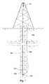
- FIG. 1is a cross-sectional diagram of an embodiment of a drill string 100 suspended by a derrick 101 .
- a bottom-hole assembly 102is located at the bottom of a bore hole 103 and comprises a bit 200 and a stabilizer assembly 104 .
- the drill string 100may penetrate soft or hard subterranean formations 105 .
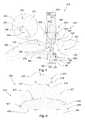
- FIG. 2discloses an embodiment wherein the drill bit 200 may be a rotary drag bit.
- the drill bit 200comprises a shank 280 which is adapted for connection to the drill string.
- coiled tubing or other types of tool stringmay be used.
- the drill bit 200 of the present inventionis intended for deep oil and gas drilling, although any type of drilling application is anticipated such as horizontal drilling, geothermal drilling, mining, exploration, on and off-shore drilling, directional drilling, water well drilling and any combination thereof.
- the bit body 201is attached to the shank 280 and comprises an end which forms a working face 202 .
- blades 203extend outwardly from the bit body 201 , each of which may include a plurality of cutting elements or inserts 210 .
- a drill bit 200 most suitable for the present inventionmay have at least three blades 203 ; preferably the drill bit 200 will have between three and seven blades 203 .
- the blades 203collectively form an inverted conical region 204 .
- Each blade 203may have a cone portion 205 , a nose portion 206 , a flank portion 207 , and a gauge portion 208 .
- Cutting inserts 210may be arrayed along any portion of the blades 203 , including the cone portion 204 , nose portion 206 , flank portion 207 , and gauge portion 208 .
- Each nozzle 212are fitted into recesses 214 formed in the working face 202 .
- Each nozzle 212may be oriented such that a jet of drilling mud ejected from the nozzles 212 engages the formation before or after the cutting elements 210 .
- the jets of drilling mudmay also be used to clean cuttings away from the working face 202 of the drill bit 200 .
- the jetsmay be used to create a sucking effect to remove drill bit cuttings adjacent the cutting elements or inserts 210 by creating a low pressure region within their vicinities.
- the cutting insertmay be a degradation assembly 310 .
- the degradation assembly 310comprises a working portion 315 coupled to a shank assembly 350 .
- the working portion 315may comprise an impact tip 320 that is brazed to a cemented metal carbide extension 330 .
- the shank assembly 350may comprise a shank 360 and a locking mechanism 370 that is slidably supported within a bore of the shank.
- the locking mechanism 370operates to couple one end of the shank 360 into the carbide extension 330 .
- the other end of the shank 360 opposite the working portion 315can be attached to a drive mechanism 390 with a press fit.
- the impact tip 320comprises a tip of superhard material 322 bonded to a cemented metal carbide substrate 326 to form the impact tip 320 , which may then be attached to the working end of the carbide extension 330 opposite a base end 337 .
- the carbide extension 330may comprise tungsten, titanium, tantalum, molybdenum, niobium, cobalt and/or combinations thereof.
- the carbide extension 330is adapted to engage or interlock with the shank assembly 350 .
- the carbide extension 330 of degradation assembly 310includes an extension cavity 334 opening inwardly from the base end 337 .
- the shank assembly 350may comprise a shank 360 having a first end 363 and a second end 367 , and with a locking mechanism 370 projecting outwardly from the first end 363 of the shank 360 .
- the first end 363 of the shank 360may be adapted to fit into the extension cavity 334 formed into the base end 337 of the carbide extension 330 .
- the shank 360is generally cylindrical.
- the second end 367 of the shank 360is press-fitted into a recess 394 of the driving mechanism 390 , which can comprise the drill bit blade 203 or bit body 201 illustrated in FIG. 2 .
- components of the shank assembly 350may be formed from a hardened material such as steel, stainless steel, hardened steel, or other materials of similar hardness.
- the components of the shank assembly 350may also be work-hardened or cold-worked in order to provide resistance to cracking or stress fractures due to forces exerted on the degradation assembly 310 by a formation, such as the formation 105 illustrated in FIG. 1 .
- the components of the shank assembly 350may be work-hardened by shot-peening or by other methods of work-hardening. At least a portion of the shank assembly 350 may also be work-hardened by stretching it during the manufacturing process.
- the shank assembly 350comprises a shank 360 and a locking mechanism 370 .
- the locking mechanism 370may be slidably supported within a bore 362 of the shank, and includes a locking head 372 projecting from the first end 363 of the shank 360 .
- the locking mechanism 370may also include a locking shaft 376 that is axially disposed within the bore 362 of the shank 360 and extending away from the locking head 372 towards the second end 367 of the shank 360 .
- the exposed end 378 of the locking shaft 376 opposite the locking head 372 and proximate the second end 367 of the shank 360is secured within or below the bore 362 , such as with a tensioning mechanism 380 or lock located within a shank cavity 364 that opens inwardly from the second end 367 of the shank.
- the first end 363 of the shank 360can be sized and shaped for insertion into the extension cavity 334 formed into the base end 337 of the carbide extension 330 , so that locking head 372 of the locking mechanism 370 projects into the extension cavity 334 upon assembly of the shank assembly 350 to the working portion 315 .
- the locking head 372 of the locking mechanism 370includes a radially-extending catch 374 that is configured to engage with an inwardly-protruding lip or catch 336 of the extension cavity 334 .
- the locking mechanism 370is adapted to couple the first end 363 of the shank 360 within the carbide extension's extension cavity 334 and restrict movement of the shank assembly 350 with respect to the carbide extension 330 .
- the working portion 315may be prevented by the locking mechanism 370 from moving in a direction parallel to a longitudinal central axis 312 of the shank 360 or degradation assembly 310 .
- the working portion 315may be prevented by the locking mechanism 370 from rotating about the central axis 312 .
- the extension cavity 334comprises an inwardly protruding lip or catch 336 .
- An insert 340is disposed intermediate the inwardly-protruding catch 336 of the cavity 330 and the radially-extending catch 374 of the locking head 372 .
- the insert 340may comprise stainless steel.
- the insert 340may comprise an elastomeric material and may be flexible.
- the insert 340may be a ring, a snap ring, a split ring, coiled ring, a rigid ring, a flexible ring, segments, balls, wedges, shims, a spring, or combinations thereof.
- the locking mechanism 370comprises a locking shaft 376 extending away from the locking head 372 .
- the radially-extending catch 374is an undercut formed in the locking head 372 .
- the insert 340 and locking head 372are disposed within the cavity 334 of the carbide extension 330 .
- the locking shaft 376extends away from the locking head 372 and is disposed within the bore 362 proximate the first end 363 of the shank 360 , and adapted for translation in a direction parallel to the central axis 402 of the degradation assembly 310 .
- the locking shaft 376may extend away from the base end 337 of the carbide assembly so that the insert 340 may be disposed around the locking shaft 376 and positioned intermediate the locking head 372 and the first end 363 of the shank 360 .
- the insert 340may comprise a breadth 344 that is larger than an opening 338 of the extension cavity 334 .
- the insert 340may compress to have a smaller breadth than the opening 338 .
- the insert 340may expand to comprise its original or substantially original breadth 344 .
- the first end 363 of the shank 360may be inserted into the cavity 334 of the carbide extension 330 .
- a nut 382may be threaded onto an exposed end 378 of the locking shaft 376 until the nut 382 contacts a ledge 366 formed within the shank cavity 364 and proximate the bore 362 and mechanically connects the locking mechanism 370 to the shank 360 .
- This contact and further threading of the nut 382 on the locking shaft 376may cause the locking shaft 376 to move toward the second end 367 of the shank 360 in a direction parallel to the longitudinal central axis 312 of the degradation assembly 310 . This may also result in bringing the radially-extending catch 374 of the locking head 372 into contact with the insert 340 , and bringing the insert 340 into contact with the inwardly-protruding lip or catch 336 of the extension cavity 334 .
- the tensioning mechanism 380is adapted to apply a rearward force on the locking head 362 of the locking mechanism 360 as the first end 363 of the shank 360 pushes in the opposite direction to apply tension along a length of the locking shaft 376 .
- the tensioning mechanism 380may comprise a press fit, a taper, and/or a nut 382 .
- the locking head 372 and insert 340are together too wide to exit the opening 338 of the cavity 334 .
- the contact between the locking head 372 and the carbide extension 330 via the insert 340may be sufficient to prevent both rotation of the working portion 315 about the central axis 312 and movement of the working portion in a direction parallel to the central axis 312 .
- the locking mechanism 370is also adapted to induce the release of the shank 360 from attachment with the carbide extension 330 by removing the nut 382 from the locking shaft 376 .
- the insert 340may be a snap ring.
- the insert 340may comprise stainless steel and may be deformed by the pressure of the locking head 372 being pulled towards the second end 367 of the shank 330 . As the insert 340 deforms it may become harder. The deformation may also cause the insert 340 to be complementary to both the inwardly-protruding lip 336 and the radially-extending catch 374 . This dually complementary insert 340 may avoid point loading or uneven loading, thereby equally distributing contact stresses. In such embodiments the insert 340 may be inserted when it is comparatively soft, and then may be work hardened while in place between the catches 336 , 374 .
- the shank assembly 350 of the degradation assembly 310may also be cold worked.
- the locking mechanism 370may be stretched to a critical point just before the strength of the locking mechanism 370 is compromised.
- the locking shaft 376 , locking head 372 , and insert 340may all be cold worked by tightening the nut 382 until the locking shaft and head 376 , 372 , and the insert 340 , reach a stretching critical point. During this stretching the insert 340 , the locking shaft 376 and the locking head 372 , may all deform to create a complementary engagement, and may then be hardened in that complementary engagement.
- the complementary engagementmay result in an interlocking or engagement between the radially-extending catch or lip 336 and the inwardly-protruding lip or catch 374 .
- both the inwardly-protruding catch 374 and the radially-extending lip or catch 336are tapers. Also in FIG. 4 , the lower portion 332 of the cavity 334 nearest the base end 406 of the carbide extension 330 comprises a uniform inward taper.
- the impact tip 420 of another embodiment of the degradation assembly 410comprises the superhard material 422 bonded to the carbide substrate 426 .
- the superhard material 422comprises a volume greater than a volume of the carbide substrate 422 .
- the superhard material 422may comprise a volume that is 75% to 175% of a volume of the carbide substrate 426 .
- the interface 425 between the substrate 426 and the superhard material 422is non-planar, which may help distribute loads on the tip 420 across a larger area of the interface 425 .
- the substrate 426may comprise a tapered surface starting from a cylindrical rim 427 of the substrate 426 and ending at an elevated flatted central region formed in the substrate 426 .
- the flatted central regionmay have a diameter of 0.20 to 0.60 percent of a diameter of the cylindrical rim 427 .
- a thickness of the superhard material from the apex 423 to the non-planar interface 425is at least 1.5 times a thickness of the substrate 426 from the non-planar interface 425 to its base 428 .
- the thickness of the superhard material from the apex 423 to the non-planar interface 425may be at least 2.0 times a thickness of the substrate 426 from the non-planar interface to its base 428 .
- the substrate 426may comprise a thickness of 0.30 to 0.65 times the thickness of the superhard material 422 .
- the thickness of the substrateis less than 0.100 inches, preferably less than 0.060 inches.
- the thickness from the apex 423 to the non-planar interface 425may be 0.190 to 0.290 inches. Together, the superhard material 422 and the substrate 426 may comprise a total thickness of 0.200 to 0.500 inches from the apex 423 to the base of the substrate 428 .
- the superhard material 422 bonded to the substrate 426may comprise a substantially conical geometry with an apex 423 comprising a 0.065 to 0.095 inch radius.
- the substantially conical geometrycomprises a first side 417 that may form a 50 to 80 degree included angle 418 with a second side 419 of the substantially conical geometry.
- an optimal included angleis 45 degrees, whereas in mining applications the inventors have discovered that an optimal included angle is between 35 and 40 degrees.
- the impact tip 420may comprise an included angle 418 to the thickness from the apex 423 to the non-planar interface 425 having a ratio of 240 to 440.
- the tip 423may comprise an included angle 418 to a total thickness from the apex 423 to a base 428 of the substrate 426 having a ratio of 160 to 280.
- a tip that maybe compatible with the present inventionis disclosed in pending U.S. patent application Ser. No. 11/673,634 to Hall.
- the superhard material 422may be a material selected from the group consisting of diamond, polycrystalline diamond, natural diamond, synthetic diamond, vapor deposited diamond, silicon bonded diamond, cobalt bonded diamond, thermally stable diamond, polycrystalline diamond with a binder concentration of 1 to 40 weight percent, infiltrated diamond, layered diamond, monolithic diamond, polished diamond, course diamond, fine diamond, cubic boron nitride, diamond impregnated matrix, diamond impregnated carbide, metal catalyzed diamond, or combinations thereof.
- the superhard material 422may also comprise infiltrated diamond.
- the superhard material 422may comprise an average diamond grain size of 1.0 to 100.0 microns.
- the superhard material 422may comprise a monolayer of diamond. For the purpose of this patent the word monolayer is defined herein as a singular continuous layer of a material of indefinite thickness.
- the superhard material 422may comprise a metal catalyst concentration of less than 5 percent by volume.
- the superhard material 422may be leached of a catalyzing material to a depth of no greater than at least 0.5 mm from a working surface 424 of the superhard material 422 .
- a description of leaching and its benefitsis disclosed in U.S. Pat. No. 6,562,462 to Griffin et al., which is herein incorporated by reference for all that it contains.
- Isolated pockets of catalyzing materialmay exist in the leached region of the superhard material 422 .
- the depth of at least 0.1 mm from the working surface 424may comprise a catalyzing material concentration of 1 percent to 5 percent by volume.
- the impact tip 420may be brazed onto the working end of the carbide extension 430 at a braze interface 429 .
- Braze material used to braze the tip 420 to the carbide extension 430may comprise a melting temperature from 700 to 1200 degrees Celsius; preferably the melting temperature is from 800 to 970 degrees Celsius.
- the braze materialmay comprise silver, gold, copper nickel, palladium, boron, chromium, silicon, germanium, aluminum, iron, cobalt, manganese, titanium, tin, gallium, vanadium, phosphorus, molybdenum, platinum, or combinations thereof.
- the braze materialmay comprise 30 to 62 weight percent palladium, preferable 40 to 50 weight percent palladium. Additionally, the braze material may comprise 30 to 60 weight percent nickel, and 3 to 15 weight percent silicon; preferably the braze material may comprise 47.2 weight percent nickel, 46.7 weight percent palladium, and 6.1 weight percent silicon.
- cooling during brazingmay be critical in some embodiments, since the heat from brazing may leave some residual stress in the bond between the carbide substrate 426 and the superhard material 422 .
- the farther away the super hard material 422 is from the braze interface 429the less thermal damage is likely to occur during brazing.
- Increasing the distance between the brazing interface 429 and the superhard material 422may increase the moment on the carbide substrate 426 and increase stresses at the brazing interface 429 upon impact.
- the shank assemblymay be press fitted into the base end of the carbide extension 430 before or after the impact tip 420 is brazed onto the working end of the carbide extension 430 .
- the shank 560 of the shank assembly 550may be press-fit into the recess 594 formed in the driving mechanism 590 .
- the shank 560 of the shank assembly 550has a coefficient of thermal expansion within 25 percent of a coefficient of thermal expansion of a material of the driving mechanism 590 . It is believed that if the coefficient of thermal expansion of the shank 560 is within 25 percent of the coefficient of thermal expansion of the driving mechanism 590 that the press-fit connection between the shank 560 and the driving mechanism 590 will not be compromised as the driving mechanism 590 increases in temperature due to friction or working conditions. It is believed that if the coefficients of thermal expansion are outside of 25 percent that the shank assemblies 550 will loose their press fit and potentially fall out of the driving mechanism 590 . In the preferred embodiment, the coefficients of thermal expansion are within 10 percent.
- 570may comprise a coefficient of thermal expansion equal to or less than the coefficient of thermal expansion of the shank 560 .
- the benefits of similar coefficientsallow for a more optimized press fit.
- the carbide substrate 526may have the same coefficient of thermal expansion as the carbide extension 530 .
- FIGS. 8 through 12disclose various embodiments of a rotary drag bit 600 A- 600 E, each comprising at least one degradation assembly.
- FIG. 8discloses a rotary drag bit 600 A that may comprise ten blades 603 A formed in the working face 602 A of the drill bit 600 A, and wherein the carbide extensions 610 A may form a portion of the blades 603 A and working face 602 A of the bit.
- the blades 603 B, 603 C, 603 D, 603 Emay be formed by the degradation assemblies 610 B, 610 C, 610 D, 610 E in the working faces 602 B, 602 C, 602 D, 602 E of the drill bits 600 B, 600 C, 600 D, 600 E, respectively, such as disclosed in FIGS. 9 through 12 , respectively.
- the drill bitmay also comprise degradation assemblies 610 A- 610 E of varying sizes.
- FIG. 13discloses an embodiment of the degradation assembly 710 incorporated into a roller cone bit 700 .
- the shank 760 of the degradation assembly 710may be press-fitted into a recess formed in the cone 790 of the roller cone bit 700 .
- the cone 790may comprise multiple degradation assemblies 710 .
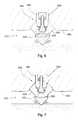
- FIG. 14discloses an embodiment of the degradation assembly 810 A adapted to a rotary drag drill bit where the apex 823 A contacts the formation 805 A at an angle 807 A with the central axis 812 A.
- the angle 807 Amay always be larger than half the included angle 418 discussed in FIG. 5 .
- the degradation assembly 810 Amay be positioned on the driving mechanism 890 A such that apex 823 A of the superhard material 822 A engages the formation 805 A and the sides 817 A, 819 A of the superhard material 822 A do not engage or contact the formation 805 A.
- FIG. 15discloses an embodiment of the degradation assembly 810 B adapted to a roller cone bit.
- the degradation assembly 810 Bmay be positioned on the driving mechanism 890 B such that apex 823 B of the superhard material 822 B engages the formation 805 B and that no more than 10 percent of the sides 817 B, 819 B of the superhard material 822 B engages or contacts the formation 805 B. It is believed that the working life of the degradation assembly 810 B may be increased as contact between the sides 817 B, 819 B of the superhard material 822 B and the formation 805 B is minimized.
- FIGS. 16-18disclose various additional drilling applications that may incorporate the degradation assembly of the present invention.
- FIG. 16discloses a drill bit 900 A typically used in water well drilling that includes degradation assembly 910 A.
- FIG. 17discloses a drill bit 900 B typically used in subterranean, horizontal drilling that includes degradation assembly 910 B.
- FIG. 18discloses a percussion bit 900 C typically used in downhole subterranean drilling that includes degradation assembly 910 C.
- the degradation assembly 1010may be incorporated into a plurality of picks 1026 attached to a rotating drum 1022 that may be connected to the underside of a pavement milling machine 1020 .
- the milling machine 1020may be a cold planer used to degrade man-made formations such as a paved surface 1005 prior to the placement of a new layer of pavement.
- Picks 1026may be attached to the rotating drum or driving mechanism 1022 bringing the picks 1026 into engagement with the formation 1005 .
- the pick 1026may include a degradation assembly 1010 and a holder 1024 , which may be a block, an extension in the block or a combination thereof.
- the holder 1024is attached to the driving mechanism 1022 , and the degradation assembly 1010 is inserted into the holder 1024 .
- the holder 1024may hold the degradation assembly 1010 at an angle offset from the direction of rotation, such that the pick 1026 engages the pavement at a preferential angle.
- Each pick 1026may be designed for high-impact resistance and long life while milling the paved surface 1005 .
- a pick that may be compatible with the present inventionis disclosed in pending U.S. patent application Ser. No. 12/020,924 to Hall.
- the degradation assembly 1010may also be incorporated in mining picks, trenching picks, excavating picks or combinations thereof.
Landscapes
- Engineering & Computer Science (AREA)
- Mining & Mineral Resources (AREA)
- Geology (AREA)
- Life Sciences & Earth Sciences (AREA)
- Mechanical Engineering (AREA)
- General Life Sciences & Earth Sciences (AREA)
- Geochemistry & Mineralogy (AREA)
- Physics & Mathematics (AREA)
- Environmental & Geological Engineering (AREA)
- Fluid Mechanics (AREA)
- Food Science & Technology (AREA)
- Earth Drilling (AREA)
- Crushing And Pulverization Processes (AREA)
Abstract
Description
Claims (21)
Priority Applications (25)
| Application Number | Priority Date | Filing Date | Title |
|---|---|---|---|
| US12/051,738US7669674B2 (en) | 2006-08-11 | 2008-03-19 | Degradation assembly |
| US12/051,689US7963617B2 (en) | 2006-08-11 | 2008-03-19 | Degradation assembly |
| US12/099,038US20080187452A1 (en) | 2006-08-11 | 2008-04-07 | Method of Forming a Workpiece |
| US12/098,962US7717365B2 (en) | 2006-08-11 | 2008-04-07 | Degradation insert with overhang |
| US12/098,934US7712693B2 (en) | 2006-08-11 | 2008-04-07 | Degradation insert with overhang |
| US12/112,815US7871133B2 (en) | 2006-08-11 | 2008-04-30 | Locking fixture |
| US12/112,743US8029068B2 (en) | 2006-08-11 | 2008-04-30 | Locking fixture for a degradation assembly |
| US12/135,654US8061784B2 (en) | 2006-08-11 | 2008-06-09 | Retention system |
| US12/135,714US8033615B2 (en) | 2006-08-11 | 2008-06-09 | Retention system |
| US12/135,595US7946656B2 (en) | 2006-08-11 | 2008-06-09 | Retention system |
| US12/146,665US8454096B2 (en) | 2006-08-11 | 2008-06-26 | High-impact resistant tool |
| PCT/US2008/069231WO2009006612A1 (en) | 2007-07-03 | 2008-07-03 | Wear resistant tool |
| US12/169,345US7946657B2 (en) | 2006-08-11 | 2008-07-08 | Retention for an insert |
| US12/177,599US7744164B2 (en) | 2006-08-11 | 2008-07-22 | Shield of a degradation assembly |
| US12/177,637US7832809B2 (en) | 2006-08-11 | 2008-07-22 | Degradation assembly shield |
| US12/177,556US7635168B2 (en) | 2006-08-11 | 2008-07-22 | Degradation assembly shield |
| US12/200,810US7661765B2 (en) | 2006-08-11 | 2008-08-28 | Braze thickness control |
| US12/200,786US8033616B2 (en) | 2006-08-11 | 2008-08-28 | Braze thickness control |
| US12/366,706US8215420B2 (en) | 2006-08-11 | 2009-02-06 | Thermally stable pointed diamond with increased impact resistance |
| US12/428,531US8500209B2 (en) | 2006-08-11 | 2009-04-23 | Manually rotatable tool |
| US12/428,541US7992944B2 (en) | 2006-08-11 | 2009-04-23 | Manually rotatable tool |
| US12/491,848US8118371B2 (en) | 2006-08-11 | 2009-06-25 | Resilient pick shank |
| US12/491,897US8500210B2 (en) | 2006-08-11 | 2009-06-25 | Resilient pick shank |
| US12/536,695US8434573B2 (en) | 2006-08-11 | 2009-08-06 | Degradation assembly |
| US13/182,421US8534767B2 (en) | 2006-08-11 | 2011-07-13 | Manually rotatable tool |
Applications Claiming Priority (21)
| Application Number | Priority Date | Filing Date | Title |
|---|---|---|---|
| US11/463,990US7320505B1 (en) | 2006-08-11 | 2006-08-11 | Attack tool |
| US11/464,008US7338135B1 (en) | 2006-08-11 | 2006-08-11 | Holder for a degradation assembly |
| US11/463,998US7384105B2 (en) | 2006-08-11 | 2006-08-11 | Attack tool |
| US11/463,953US7464993B2 (en) | 2006-08-11 | 2006-08-11 | Attack tool |
| US11/463,975US7445294B2 (en) | 2006-08-11 | 2006-08-11 | Attack tool |
| US11/463,962US7413256B2 (en) | 2006-08-11 | 2006-08-11 | Washer for a degradation assembly |
| US11/686,831US7568770B2 (en) | 2006-06-16 | 2007-03-15 | Superhard composite material bonded to a steel body |
| US11/695,672US7396086B1 (en) | 2007-03-15 | 2007-04-03 | Press-fit pick |
| US11/742,261US7469971B2 (en) | 2006-08-11 | 2007-04-30 | Lubricated pick |
| US11/742,304US7475948B2 (en) | 2006-08-11 | 2007-04-30 | Pick with a bearing |
| US76686507A | 2007-06-22 | 2007-06-22 | |
| US11/766,903US20130341999A1 (en) | 2006-08-11 | 2007-06-22 | Attack Tool with an Interruption |
| US11/773,271US7997661B2 (en) | 2006-08-11 | 2007-07-03 | Tapered bore in a pick |
| US11/829,761US7722127B2 (en) | 2006-08-11 | 2007-07-27 | Pick shank in axial tension |
| US11/844,586US7600823B2 (en) | 2006-08-11 | 2007-08-24 | Pick assembly |
| US11/947,644US8007051B2 (en) | 2006-08-11 | 2007-11-29 | Shank assembly |
| US11/971,965US7648210B2 (en) | 2006-08-11 | 2008-01-10 | Pick with an interlocked bolster |
| US12/021,051US8123302B2 (en) | 2006-08-11 | 2008-01-28 | Impact tool |
| US12/021,019US8485609B2 (en) | 2006-08-11 | 2008-01-28 | Impact tool |
| US12/051,586US8007050B2 (en) | 2006-08-11 | 2008-03-19 | Degradation assembly |
| US12/051,689US7963617B2 (en) | 2006-08-11 | 2008-03-19 | Degradation assembly |
Related Parent Applications (2)
| Application Number | Title | Priority Date | Filing Date |
|---|---|---|---|
| US12/051,586ContinuationUS8007050B2 (en) | 2006-08-11 | 2008-03-19 | Degradation assembly |
| US12/051,586Continuation-In-PartUS8007050B2 (en) | 2006-08-11 | 2008-03-19 | Degradation assembly |
Related Child Applications (3)
| Application Number | Title | Priority Date | Filing Date |
|---|---|---|---|
| US12/051,738Continuation-In-PartUS7669674B2 (en) | 2006-08-11 | 2008-03-19 | Degradation assembly |
| US12/051,738ContinuationUS7669674B2 (en) | 2006-08-11 | 2008-03-19 | Degradation assembly |
| US12/098,934ContinuationUS7712693B2 (en) | 2006-08-11 | 2008-04-07 | Degradation insert with overhang |
Publications (2)
| Publication Number | Publication Date |
|---|---|
| US20080164072A1 US20080164072A1 (en) | 2008-07-10 |
| US7963617B2true US7963617B2 (en) | 2011-06-21 |
Family
ID=39415790
Family Applications (2)
| Application Number | Title | Priority Date | Filing Date |
|---|---|---|---|
| US12/051,689Expired - Fee RelatedUS7963617B2 (en) | 2006-08-11 | 2008-03-19 | Degradation assembly |
| US12/098,934Expired - Fee RelatedUS7712693B2 (en) | 2006-08-11 | 2008-04-07 | Degradation insert with overhang |
Family Applications After (1)
| Application Number | Title | Priority Date | Filing Date |
|---|---|---|---|
| US12/098,934Expired - Fee RelatedUS7712693B2 (en) | 2006-08-11 | 2008-04-07 | Degradation insert with overhang |
Country Status (1)
| Country | Link |
|---|---|
| US (2) | US7963617B2 (en) |
Cited By (42)
| Publication number | Priority date | Publication date | Assignee | Title |
|---|---|---|---|---|
| US20080115978A1 (en)* | 2006-08-11 | 2008-05-22 | Hall David R | Shank Assembly with a Tensioned Element |
| US9518464B2 (en) | 2012-10-19 | 2016-12-13 | The Sollami Company | Combination polycrystalline diamond bit and bit holder |
| US9879531B2 (en) | 2014-02-26 | 2018-01-30 | The Sollami Company | Bit holder shank and differential interference between the shank distal portion and the bit holder block bore |
| US9909416B1 (en) | 2013-09-18 | 2018-03-06 | The Sollami Company | Diamond tipped unitary holder/bit |
| US9976418B2 (en) | 2014-04-02 | 2018-05-22 | The Sollami Company | Bit/holder with enlarged ballistic tip insert |
| US9988903B2 (en) | 2012-10-19 | 2018-06-05 | The Sollami Company | Combination polycrystalline diamond bit and bit holder |
| US10072501B2 (en) | 2010-08-27 | 2018-09-11 | The Sollami Company | Bit holder |
| US10107097B1 (en) | 2012-10-19 | 2018-10-23 | The Sollami Company | Combination polycrystalline diamond bit and bit holder |
| US10107098B2 (en) | 2016-03-15 | 2018-10-23 | The Sollami Company | Bore wear compensating bit holder and bit holder block |
| US10105870B1 (en) | 2012-10-19 | 2018-10-23 | The Sollami Company | Combination polycrystalline diamond bit and bit holder |
| US10180065B1 (en) | 2015-10-05 | 2019-01-15 | The Sollami Company | Material removing tool for road milling mining and trenching operations |
| US10260342B1 (en) | 2012-10-19 | 2019-04-16 | The Sollami Company | Combination polycrystalline diamond bit and bit holder |
| US10315175B2 (en) | 2012-11-15 | 2019-06-11 | Smith International, Inc. | Method of making carbonate PCD and sintering carbonate PCD on carbide substrate |
| US10323515B1 (en) | 2012-10-19 | 2019-06-18 | The Sollami Company | Tool with steel sleeve member |
| US10337324B2 (en) | 2015-01-07 | 2019-07-02 | The Sollami Company | Various bit holders and unitary bit/holders for use with shortened depth bit holder blocks |
| US10370966B1 (en) | 2014-04-23 | 2019-08-06 | The Sollami Company | Rear of base block |
| US10385689B1 (en) | 2010-08-27 | 2019-08-20 | The Sollami Company | Bit holder |
| US10415386B1 (en) | 2013-09-18 | 2019-09-17 | The Sollami Company | Insertion-removal tool for holder/bit |
| US10502056B2 (en) | 2015-09-30 | 2019-12-10 | The Sollami Company | Reverse taper shanks and complementary base block bores for bit assemblies |
| US10577931B2 (en) | 2016-03-05 | 2020-03-03 | The Sollami Company | Bit holder (pick) with shortened shank and angular differential between the shank and base block bore |
| US10590710B2 (en) | 2016-12-09 | 2020-03-17 | Baker Hughes, A Ge Company, Llc | Cutting elements, earth-boring tools including the cutting elements, and methods of forming the cutting elements |
| US10598013B2 (en) | 2010-08-27 | 2020-03-24 | The Sollami Company | Bit holder with shortened nose portion |
| US10612376B1 (en) | 2016-03-15 | 2020-04-07 | The Sollami Company | Bore wear compensating retainer and washer |
| US10612375B2 (en) | 2016-04-01 | 2020-04-07 | The Sollami Company | Bit retainer |
| US10633971B2 (en) | 2016-03-07 | 2020-04-28 | The Sollami Company | Bit holder with enlarged tire portion and narrowed bit holder block |
| US10767478B2 (en) | 2013-09-18 | 2020-09-08 | The Sollami Company | Diamond tipped unitary holder/bit |
| US10794181B2 (en) | 2014-04-02 | 2020-10-06 | The Sollami Company | Bit/holder with enlarged ballistic tip insert |
| US10876401B1 (en) | 2016-07-26 | 2020-12-29 | The Sollami Company | Rotational style tool bit assembly |
| US10876402B2 (en) | 2014-04-02 | 2020-12-29 | The Sollami Company | Bit tip insert |
| US10947844B1 (en) | 2013-09-18 | 2021-03-16 | The Sollami Company | Diamond Tipped Unitary Holder/Bit |
| US10968739B1 (en) | 2013-09-18 | 2021-04-06 | The Sollami Company | Diamond tipped unitary holder/bit |
| US10968738B1 (en) | 2017-03-24 | 2021-04-06 | The Sollami Company | Remanufactured conical bit |
| US10995613B1 (en) | 2013-09-18 | 2021-05-04 | The Sollami Company | Diamond tipped unitary holder/bit |
| US11103939B2 (en) | 2018-07-18 | 2021-08-31 | The Sollami Company | Rotatable bit cartridge |
| US11168563B1 (en) | 2013-10-16 | 2021-11-09 | The Sollami Company | Bit holder with differential interference |
| US11187080B2 (en) | 2018-04-24 | 2021-11-30 | The Sollami Company | Conical bit with diamond insert |
| US11261731B1 (en) | 2014-04-23 | 2022-03-01 | The Sollami Company | Bit holder and unitary bit/holder for use in shortened depth base blocks |
| US11279012B1 (en) | 2017-09-15 | 2022-03-22 | The Sollami Company | Retainer insertion and extraction tool |
| US11339656B1 (en) | 2014-02-26 | 2022-05-24 | The Sollami Company | Rear of base block |
| US11339654B2 (en) | 2014-04-02 | 2022-05-24 | The Sollami Company | Insert with heat transfer bore |
| US11891895B1 (en) | 2014-04-23 | 2024-02-06 | The Sollami Company | Bit holder with annular rings |
| US12345158B1 (en) | 2019-06-20 | 2025-07-01 | The Sollami Company | Bit tip insert |
Families Citing this family (5)
| Publication number | Priority date | Publication date | Assignee | Title |
|---|---|---|---|---|
| CN101761106A (en)* | 2008-10-23 | 2010-06-30 | 朱大悦 | Technology for automatically exploiting groundwater |
| GB201105438D0 (en) | 2011-03-31 | 2011-05-18 | Element Six Holding Gmbh | Pick apparatus and pick tools |
| DE102011054573A1 (en)* | 2011-10-18 | 2013-04-18 | Betek Gmbh & Co. Kg | Wear protective element |
| RU2564492C2 (en)* | 2013-10-08 | 2015-10-10 | Федеральное государственное бюджетное образовательное учреждение высшего профессионального образования "Красноярский государственный аграрный университет" (ФГБОУ ВПО КрасГАУ) | Rotary vortex mill |
| RU209676U1 (en)* | 2021-03-17 | 2022-03-18 | Федеральное государственное бюджетное учреждение науки Федеральный исследовательский центр "Якутский научный центр Сибирского отделения Российской академии наук" | Centrifugal conical grinder with malleable particle isometrization zone |
Citations (113)
| Publication number | Priority date | Publication date | Assignee | Title |
|---|---|---|---|---|
| US2004315A (en) | 1932-08-29 | 1935-06-11 | Thomas R Mcdonald | Packing liner |
| US2124438A (en) | 1935-04-05 | 1938-07-19 | Gen Electric | Soldered article or machine part |
| US3254392A (en) | 1963-11-13 | 1966-06-07 | Warner Swasey Co | Insert bit for cutoff and like tools |
| US3342531A (en)* | 1965-02-16 | 1967-09-19 | Cincinnati Mine Machinery Co | Conical cutter bits held by resilient retainer for free rotation |
| US3746396A (en) | 1970-12-31 | 1973-07-17 | Continental Oil Co | Cutter bit and method of causing rotation thereof |
| US3807804A (en) | 1972-09-12 | 1974-04-30 | Kennametal Inc | Impacting tool with tungsten carbide insert tip |
| US3830321A (en) | 1973-02-20 | 1974-08-20 | Kennametal Inc | Excavating tool and a bit for use therewith |
| US3932952A (en) | 1973-12-17 | 1976-01-20 | Caterpillar Tractor Co. | Multi-material ripper tip |
| US3945681A (en) | 1973-12-07 | 1976-03-23 | Western Rock Bit Company Limited | Cutter assembly |
| US4005914A (en) | 1974-08-20 | 1977-02-01 | Rolls-Royce (1971) Limited | Surface coating for machine elements having rubbing surfaces |
| US4006936A (en) | 1975-11-06 | 1977-02-08 | Dresser Industries, Inc. | Rotary cutter for a road planer |
| US4098362A (en) | 1976-11-30 | 1978-07-04 | General Electric Company | Rotary drill bit and method for making same |
| US4109737A (en) | 1976-06-24 | 1978-08-29 | General Electric Company | Rotary drill bit |
| GB2004315A (en) | 1977-09-17 | 1979-03-28 | Krupp Gmbh | Tool for cutting rocks and minerals. |
| US4149753A (en) | 1976-07-06 | 1979-04-17 | Gewerkschaft Eisenhutte Westfalia | Cutter bit assemblies |
| US4156329A (en) | 1977-05-13 | 1979-05-29 | General Electric Company | Method for fabricating a rotary drill bit and composite compact cutters therefor |
| US4199035A (en) | 1978-04-24 | 1980-04-22 | General Electric Company | Cutting and drilling apparatus with threadably attached compacts |
| US4201421A (en) | 1978-09-20 | 1980-05-06 | Besten Leroy E Den | Mining machine bit and mounting thereof |
| US4277106A (en) | 1979-10-22 | 1981-07-07 | Syndrill Carbide Diamond Company | Self renewing working tip mining pick |
| GB2037223B (en) | 1978-11-28 | 1982-10-06 | Wirtgen Reinhard | Milling cutter for a milling device |
| US4439250A (en) | 1983-06-09 | 1984-03-27 | International Business Machines Corporation | Solder/braze-stop composition |
| US4465221A (en) | 1982-09-28 | 1984-08-14 | Schmidt Glenn H | Method of sustaining metallic golf club head sole plate profile by confined brazing or welding |
| US4484644A (en) | 1980-09-02 | 1984-11-27 | Ingersoll-Rand Company | Sintered and forged article, and method of forming same |
| US4489986A (en) | 1982-11-01 | 1984-12-25 | Dziak William A | Wear collar device for rotatable cutter bit |
| DE3500261C2 (en) | 1985-01-05 | 1987-01-29 | Bergwerksverband Gmbh, 4300 Essen | Chisels for cutting mineral raw materials |
| US4678237A (en) | 1982-08-06 | 1987-07-07 | Huddy Diamond Crown Setting Company (Proprietary) Limited | Cutter inserts for picks |
| US4682987A (en) | 1981-04-16 | 1987-07-28 | Brady William J | Method and composition for producing hard surface carbide insert tools |
| US4688856A (en) | 1984-10-27 | 1987-08-25 | Gerd Elfgen | Round cutting tool |
| US4725098A (en) | 1986-12-19 | 1988-02-16 | Kennametal Inc. | Erosion resistant cutting bit with hardfacing |
| US4729603A (en) | 1984-11-22 | 1988-03-08 | Gerd Elfgen | Round cutting tool for cutters |
| US4765687A (en) | 1986-02-19 | 1988-08-23 | Innovation Limited | Tip and mineral cutter pick |
| US4765686A (en) | 1987-10-01 | 1988-08-23 | Gte Valenite Corporation | Rotatable cutting bit for a mining machine |
| US4776862A (en) | 1987-12-08 | 1988-10-11 | Wiand Ronald C | Brazing of diamond |
| US4880154A (en) | 1986-04-03 | 1989-11-14 | Klaus Tank | Brazing |
| DE3818213A1 (en) | 1988-05-28 | 1989-11-30 | Gewerk Eisenhuette Westfalia | Pick, in particular for underground winning machines, heading machines and the like |
| US4932723A (en) | 1989-06-29 | 1990-06-12 | Mills Ronald D | Cutting-bit holding support block shield |
| US4940288A (en) | 1988-07-20 | 1990-07-10 | Kennametal Inc. | Earth engaging cutter bit |
| US4944559A (en) | 1988-06-02 | 1990-07-31 | Societe Industrielle De Combustible Nucleaire | Tool for a mine working machine comprising a diamond-charged abrasive component |
| US4951762A (en) | 1988-07-28 | 1990-08-28 | Sandvik Ab | Drill bit with cemented carbide inserts |
| EP0412287A2 (en) | 1989-08-11 | 1991-02-13 | VERSCHLEISS-TECHNIK DR.-ING. HANS WAHL GMBH & CO. | Pick or similar tool for the extraction of raw materials or the recycling |
| US5011515A (en) | 1989-08-07 | 1991-04-30 | Frushour Robert H | Composite polycrystalline diamond compact with improved impact resistance |
| US5112165A (en) | 1989-04-24 | 1992-05-12 | Sandvik Ab | Tool for cutting solid material |
| US5141289A (en) | 1988-07-20 | 1992-08-25 | Kennametal Inc. | Cemented carbide tip |
| US5154245A (en) | 1990-04-19 | 1992-10-13 | Sandvik Ab | Diamond rock tools for percussive and rotary crushing rock drilling |
| US5186892A (en) | 1991-01-17 | 1993-02-16 | U.S. Synthetic Corporation | Method of healing cracks and flaws in a previously sintered cemented carbide tools |
| EP0295151B1 (en) | 1987-06-12 | 1993-07-28 | Camco Drilling Group Limited | Improvements in or relating to the manufacture of cutting elements for rotary drill bits |
| US5251964A (en) | 1992-08-03 | 1993-10-12 | Gte Valenite Corporation | Cutting bit mount having carbide inserts and method for mounting the same |
| JPH05280273A (en) | 1992-03-31 | 1993-10-26 | Mitsubishi Materials Corp | Bound-pick and drilling tool |
| DE4039217C2 (en) | 1990-12-08 | 1993-11-11 | Willi Jacobs | Picks |
| US5261499A (en) | 1992-07-15 | 1993-11-16 | Kennametal Inc. | Two-piece rotatable cutting bit |
| US5332348A (en) | 1987-03-31 | 1994-07-26 | Lemelson Jerome H | Fastening devices |
| US5417475A (en) | 1992-08-19 | 1995-05-23 | Sandvik Ab | Tool comprised of a holder body and a hard insert and method of using same |
| US5447208A (en) | 1993-11-22 | 1995-09-05 | Baker Hughes Incorporated | Superhard cutting element having reduced surface roughness and method of modifying |
| US5535839A (en) | 1995-06-07 | 1996-07-16 | Brady; William J. | Roof drill bit with radial domed PCD inserts |
| US5542993A (en) | 1989-10-10 | 1996-08-06 | Alliedsignal Inc. | Low melting nickel-palladium-silicon brazing alloy |
| US5738698A (en) | 1994-07-29 | 1998-04-14 | Saint Gobain/Norton Company Industrial Ceramics Corp. | Brazing of diamond film to tungsten carbide |
| US5823632A (en) | 1996-06-13 | 1998-10-20 | Burkett; Kenneth H. | Self-sharpening nosepiece with skirt for attack tools |
| US5837071A (en) | 1993-11-03 | 1998-11-17 | Sandvik Ab | Diamond coated cutting tool insert and method of making same |
| US5842747A (en) | 1997-02-24 | 1998-12-01 | Keystone Engineering & Manufacturing Corporation | Apparatus for roadway surface reclaiming drum |
| US5845547A (en) | 1996-09-09 | 1998-12-08 | The Sollami Company | Tool having a tungsten carbide insert |
| US5875862A (en) | 1995-07-14 | 1999-03-02 | U.S. Synthetic Corporation | Polycrystalline diamond cutter with integral carbide/diamond transition layer |
| US5935718A (en) | 1994-11-07 | 1999-08-10 | General Electric Company | Braze blocking insert for liquid phase brazing operation |
| US5934542A (en) | 1994-03-31 | 1999-08-10 | Sumitomo Electric Industries, Inc. | High strength bonding tool and a process for production of the same |
| US5944129A (en) | 1997-11-28 | 1999-08-31 | U.S. Synthetic Corporation | Surface finish for non-planar inserts |
| US5992405A (en) | 1998-01-02 | 1999-11-30 | The Sollami Company | Tool mounting for a cutting tool |
| US6006846A (en) | 1997-09-19 | 1999-12-28 | Baker Hughes Incorporated | Cutting element, drill bit, system and method for drilling soft plastic formations |
| US6019434A (en) | 1997-10-07 | 2000-02-01 | Fansteel Inc. | Point attack bit |
| US6044920A (en) | 1997-07-15 | 2000-04-04 | Kennametal Inc. | Rotatable cutting bit assembly with cutting inserts |
| US6056911A (en) | 1998-05-27 | 2000-05-02 | Camco International (Uk) Limited | Methods of treating preform elements including polycrystalline diamond bonded to a substrate |
| US6065552A (en) | 1998-07-20 | 2000-05-23 | Baker Hughes Incorporated | Cutting elements with binderless carbide layer |
| US6113195A (en) | 1998-10-08 | 2000-09-05 | Sandvik Ab | Rotatable cutting bit and bit washer therefor |
| US6170917B1 (en) | 1997-08-27 | 2001-01-09 | Kennametal Inc. | Pick-style tool with a cermet insert having a Co-Ni-Fe-binder |
| US6193770B1 (en) | 1997-04-04 | 2001-02-27 | Chien-Min Sung | Brazed diamond tools by infiltration |
| US6196910B1 (en) | 1998-08-10 | 2001-03-06 | General Electric Company | Polycrystalline diamond compact cutter with improved cutting by preventing chip build up |
| US6196636B1 (en) | 1999-03-22 | 2001-03-06 | Larry J. McSweeney | Cutting bit insert configured in a polygonal pyramid shape and having a ring mounted in surrounding relationship with the insert |
| US6199956B1 (en) | 1998-01-28 | 2001-03-13 | Betek Bergbau- Und Hartmetalltechnik Karl-Heinz-Simon Gmbh & Co. Kg | Round-shank bit for a coal cutting machine |
| US6216805B1 (en) | 1999-07-12 | 2001-04-17 | Baker Hughes Incorporated | Dual grade carbide substrate for earth-boring drill bit cutting elements, drill bits so equipped, and methods |
| US6270165B1 (en) | 1999-10-22 | 2001-08-07 | Sandvik Rock Tools, Inc. | Cutting tool for breaking hard material, and a cutting cap therefor |
| US6341823B1 (en) | 2000-05-22 | 2002-01-29 | The Sollami Company | Rotatable cutting tool with notched radial fins |
| DE19821147C2 (en) | 1998-05-12 | 2002-02-07 | Betek Bergbau & Hartmetall | Attack cutting tools |
| US6354771B1 (en) | 1998-12-12 | 2002-03-12 | Boart Longyear Gmbh & Co. Kg | Cutting or breaking tool as well as cutting insert for the latter |
| US6364420B1 (en) | 1999-03-22 | 2002-04-02 | The Sollami Company | Bit and bit holder/block having a predetermined area of failure |
| US6371567B1 (en) | 1999-03-22 | 2002-04-16 | The Sollami Company | Bit holders and bit blocks for road milling, mining and trenching equipment |
| US6375272B1 (en) | 2000-03-24 | 2002-04-23 | Kennametal Inc. | Rotatable cutting tool insert |
| US6419278B1 (en) | 2000-05-31 | 2002-07-16 | Dana Corporation | Automotive hose coupling |
| US6478383B1 (en) | 1999-10-18 | 2002-11-12 | Kennametal Pc Inc. | Rotatable cutting tool-tool holder assembly |
| US20020175555A1 (en) | 2001-05-23 | 2002-11-28 | Mercier Greg D. | Rotatable cutting bit and retainer sleeve therefor |
| US6499547B2 (en) | 1999-01-13 | 2002-12-31 | Baker Hughes Incorporated | Multiple grade carbide for diamond capped insert |
| US6517902B2 (en) | 1998-05-27 | 2003-02-11 | Camco International (Uk) Limited | Methods of treating preform elements |
| DE10163717C1 (en) | 2001-12-21 | 2003-05-28 | Betek Bergbau & Hartmetall | Chisel, for a coal cutter, comprises a head having cuttings-receiving pockets arranged a distance apart between the tip and an annular groove and running around the head to form partially concave cuttings-retaining surfaces facing the tip |
| US20030140350A1 (en) | 2002-01-24 | 2003-07-24 | Daniel Watkins | Enhanced personal video recorder |
| US20030209366A1 (en) | 2002-05-07 | 2003-11-13 | Mcalvain Bruce William | Rotatable point-attack bit with protective body |
| US20030234280A1 (en) | 2002-03-28 | 2003-12-25 | Cadden Charles H. | Braze system and method for reducing strain in a braze joint |
| US6685273B1 (en) | 2000-02-15 | 2004-02-03 | The Sollami Company | Streamlining bit assemblies for road milling, mining and trenching equipment |
| US20040026983A1 (en)* | 2002-08-07 | 2004-02-12 | Mcalvain Bruce William | Monolithic point-attack bit |
| US6692083B2 (en) | 2002-06-14 | 2004-02-17 | Keystone Engineering & Manufacturing Corporation | Replaceable wear surface for bit support |
| US6709065B2 (en) | 2002-01-30 | 2004-03-23 | Sandvik Ab | Rotary cutting bit with material-deflecting ledge |
| US20040065484A1 (en) | 2002-10-08 | 2004-04-08 | Mcalvain Bruce William | Diamond tip point-attack bit |
| US6719074B2 (en) | 2001-03-23 | 2004-04-13 | Japan National Oil Corporation | Insert chip of oil-drilling tricone bit, manufacturing method thereof and oil-drilling tricone bit |
| US6733087B2 (en) | 2002-08-10 | 2004-05-11 | David R. Hall | Pick for disintegrating natural and man-made materials |
| US6739327B2 (en) | 2001-12-31 | 2004-05-25 | The Sollami Company | Cutting tool with hardened tip having a tapered base |
| US6758530B2 (en) | 2001-09-18 | 2004-07-06 | The Sollami Company | Hardened tip for cutting tools |
| US6786557B2 (en) | 2000-12-20 | 2004-09-07 | Kennametal Inc. | Protective wear sleeve having tapered lock and retainer |
| US6824225B2 (en) | 2001-09-10 | 2004-11-30 | Kennametal Inc. | Embossed washer |
| US6851758B2 (en) | 2002-12-20 | 2005-02-08 | Kennametal Inc. | Rotatable bit having a resilient retainer sleeve with clearance |
| US6854810B2 (en) | 2000-12-20 | 2005-02-15 | Kennametal Inc. | T-shaped cutter tool assembly with wear sleeve |
| US6861137B2 (en) | 2000-09-20 | 2005-03-01 | Reedhycalog Uk Ltd | High volume density polycrystalline diamond with working surfaces depleted of catalyzing material |
| US6889890B2 (en) | 2001-10-09 | 2005-05-10 | Hohoemi Brains, Inc. | Brazing-filler material and method for brazing diamond |
| US20050159840A1 (en) | 2004-01-16 | 2005-07-21 | Wen-Jong Lin | System for surface finishing a workpiece |
| US20050173966A1 (en) | 2004-02-06 | 2005-08-11 | Mouthaan Daniel J. | Non-rotatable protective member, cutting tool using the protective member, and cutting tool assembly using the protective member |
| US6966611B1 (en) | 2002-01-24 | 2005-11-22 | The Sollami Company | Rotatable tool assembly |
| US20060237236A1 (en) | 2005-04-26 | 2006-10-26 | Harold Sreshta | Composite structure having a non-planar interface and method of making same |
| US7204560B2 (en) | 2003-08-15 | 2007-04-17 | Sandvik Intellectual Property Ab | Rotary cutting bit with material-deflecting ledge |
Family Cites Families (8)
| Publication number | Priority date | Publication date | Assignee | Title |
|---|---|---|---|---|
| US883619A (en)* | 1906-03-26 | 1908-03-31 | Ferdinand Mora Canda | Crusher plate, head, and the like. |
| US3241777A (en)* | 1965-04-08 | 1966-03-22 | Hanna Mining Co | Crusher jaw construction |
| US3630321A (en)* | 1970-06-05 | 1971-12-28 | Harold S Hollnagel | Surge brake damper |
| KR0138254B1 (en)* | 1989-03-10 | 1998-04-27 | 니시오카 시게루 | Stirrer |
| US5967431A (en)* | 1996-03-18 | 1999-10-19 | Astec Industries, Inc. | Rock crusher having crushing-enhancing inserts, method for its production, and method for its use |
| AU781290B2 (en)* | 2000-05-18 | 2005-05-12 | Smith International, Inc. | Rolling cone bit with elements fanned along the gage curve |
| JP3899986B2 (en) | 2002-01-25 | 2007-03-28 | 株式会社デンソー | How to apply brazing material |
| US6889690B2 (en)* | 2002-05-10 | 2005-05-10 | Oriel Therapeutics, Inc. | Dry powder inhalers, related blister devices, and associated methods of dispensing dry powder substances and fabricating blister packages |
- 2008
- 2008-03-19USUS12/051,689patent/US7963617B2/ennot_activeExpired - Fee Related
- 2008-04-07USUS12/098,934patent/US7712693B2/ennot_activeExpired - Fee Related
Patent Citations (119)
| Publication number | Priority date | Publication date | Assignee | Title |
|---|---|---|---|---|
| US2004315A (en) | 1932-08-29 | 1935-06-11 | Thomas R Mcdonald | Packing liner |
| US2124438A (en) | 1935-04-05 | 1938-07-19 | Gen Electric | Soldered article or machine part |
| US3254392A (en) | 1963-11-13 | 1966-06-07 | Warner Swasey Co | Insert bit for cutoff and like tools |
| US3342531A (en)* | 1965-02-16 | 1967-09-19 | Cincinnati Mine Machinery Co | Conical cutter bits held by resilient retainer for free rotation |
| US3746396A (en) | 1970-12-31 | 1973-07-17 | Continental Oil Co | Cutter bit and method of causing rotation thereof |
| US3807804A (en) | 1972-09-12 | 1974-04-30 | Kennametal Inc | Impacting tool with tungsten carbide insert tip |
| US3830321A (en) | 1973-02-20 | 1974-08-20 | Kennametal Inc | Excavating tool and a bit for use therewith |
| US3945681A (en) | 1973-12-07 | 1976-03-23 | Western Rock Bit Company Limited | Cutter assembly |
| US3932952A (en) | 1973-12-17 | 1976-01-20 | Caterpillar Tractor Co. | Multi-material ripper tip |
| US4005914A (en) | 1974-08-20 | 1977-02-01 | Rolls-Royce (1971) Limited | Surface coating for machine elements having rubbing surfaces |
| US4006936A (en) | 1975-11-06 | 1977-02-08 | Dresser Industries, Inc. | Rotary cutter for a road planer |
| US4109737A (en) | 1976-06-24 | 1978-08-29 | General Electric Company | Rotary drill bit |
| US4149753A (en) | 1976-07-06 | 1979-04-17 | Gewerkschaft Eisenhutte Westfalia | Cutter bit assemblies |
| US4098362A (en) | 1976-11-30 | 1978-07-04 | General Electric Company | Rotary drill bit and method for making same |
| US4156329A (en) | 1977-05-13 | 1979-05-29 | General Electric Company | Method for fabricating a rotary drill bit and composite compact cutters therefor |
| GB2004315A (en) | 1977-09-17 | 1979-03-28 | Krupp Gmbh | Tool for cutting rocks and minerals. |
| US4199035A (en) | 1978-04-24 | 1980-04-22 | General Electric Company | Cutting and drilling apparatus with threadably attached compacts |
| US4201421A (en) | 1978-09-20 | 1980-05-06 | Besten Leroy E Den | Mining machine bit and mounting thereof |
| GB2037223B (en) | 1978-11-28 | 1982-10-06 | Wirtgen Reinhard | Milling cutter for a milling device |
| US4277106A (en) | 1979-10-22 | 1981-07-07 | Syndrill Carbide Diamond Company | Self renewing working tip mining pick |
| US4484644A (en) | 1980-09-02 | 1984-11-27 | Ingersoll-Rand Company | Sintered and forged article, and method of forming same |
| US4682987A (en) | 1981-04-16 | 1987-07-28 | Brady William J | Method and composition for producing hard surface carbide insert tools |
| US4678237A (en) | 1982-08-06 | 1987-07-07 | Huddy Diamond Crown Setting Company (Proprietary) Limited | Cutter inserts for picks |
| US4465221A (en) | 1982-09-28 | 1984-08-14 | Schmidt Glenn H | Method of sustaining metallic golf club head sole plate profile by confined brazing or welding |
| US4489986A (en) | 1982-11-01 | 1984-12-25 | Dziak William A | Wear collar device for rotatable cutter bit |
| US4439250A (en) | 1983-06-09 | 1984-03-27 | International Business Machines Corporation | Solder/braze-stop composition |
| US4688856A (en) | 1984-10-27 | 1987-08-25 | Gerd Elfgen | Round cutting tool |
| US4729603A (en) | 1984-11-22 | 1988-03-08 | Gerd Elfgen | Round cutting tool for cutters |
| DE3500261C2 (en) | 1985-01-05 | 1987-01-29 | Bergwerksverband Gmbh, 4300 Essen | Chisels for cutting mineral raw materials |
| US4765687A (en) | 1986-02-19 | 1988-08-23 | Innovation Limited | Tip and mineral cutter pick |
| US4880154A (en) | 1986-04-03 | 1989-11-14 | Klaus Tank | Brazing |
| US4725098A (en) | 1986-12-19 | 1988-02-16 | Kennametal Inc. | Erosion resistant cutting bit with hardfacing |
| US5332348A (en) | 1987-03-31 | 1994-07-26 | Lemelson Jerome H | Fastening devices |
| EP0295151B1 (en) | 1987-06-12 | 1993-07-28 | Camco Drilling Group Limited | Improvements in or relating to the manufacture of cutting elements for rotary drill bits |
| US4765686A (en) | 1987-10-01 | 1988-08-23 | Gte Valenite Corporation | Rotatable cutting bit for a mining machine |
| US4776862A (en) | 1987-12-08 | 1988-10-11 | Wiand Ronald C | Brazing of diamond |
| DE3818213A1 (en) | 1988-05-28 | 1989-11-30 | Gewerk Eisenhuette Westfalia | Pick, in particular for underground winning machines, heading machines and the like |
| US4944559A (en) | 1988-06-02 | 1990-07-31 | Societe Industrielle De Combustible Nucleaire | Tool for a mine working machine comprising a diamond-charged abrasive component |
| US4940288A (en) | 1988-07-20 | 1990-07-10 | Kennametal Inc. | Earth engaging cutter bit |
| US5141289A (en) | 1988-07-20 | 1992-08-25 | Kennametal Inc. | Cemented carbide tip |
| US4951762A (en) | 1988-07-28 | 1990-08-28 | Sandvik Ab | Drill bit with cemented carbide inserts |
| US5112165A (en) | 1989-04-24 | 1992-05-12 | Sandvik Ab | Tool for cutting solid material |
| US4932723A (en) | 1989-06-29 | 1990-06-12 | Mills Ronald D | Cutting-bit holding support block shield |
| US5011515A (en) | 1989-08-07 | 1991-04-30 | Frushour Robert H | Composite polycrystalline diamond compact with improved impact resistance |
| US5011515B1 (en) | 1989-08-07 | 1999-07-06 | Robert H Frushour | Composite polycrystalline diamond compact with improved impact resistance |
| EP0412287A2 (en) | 1989-08-11 | 1991-02-13 | VERSCHLEISS-TECHNIK DR.-ING. HANS WAHL GMBH & CO. | Pick or similar tool for the extraction of raw materials or the recycling |
| US5542993A (en) | 1989-10-10 | 1996-08-06 | Alliedsignal Inc. | Low melting nickel-palladium-silicon brazing alloy |
| US5154245A (en) | 1990-04-19 | 1992-10-13 | Sandvik Ab | Diamond rock tools for percussive and rotary crushing rock drilling |
| DE4039217C2 (en) | 1990-12-08 | 1993-11-11 | Willi Jacobs | Picks |
| US5186892A (en) | 1991-01-17 | 1993-02-16 | U.S. Synthetic Corporation | Method of healing cracks and flaws in a previously sintered cemented carbide tools |
| JPH05280273A (en) | 1992-03-31 | 1993-10-26 | Mitsubishi Materials Corp | Bound-pick and drilling tool |
| US5261499A (en) | 1992-07-15 | 1993-11-16 | Kennametal Inc. | Two-piece rotatable cutting bit |
| US5251964A (en) | 1992-08-03 | 1993-10-12 | Gte Valenite Corporation | Cutting bit mount having carbide inserts and method for mounting the same |
| US5417475A (en) | 1992-08-19 | 1995-05-23 | Sandvik Ab | Tool comprised of a holder body and a hard insert and method of using same |
| US5837071A (en) | 1993-11-03 | 1998-11-17 | Sandvik Ab | Diamond coated cutting tool insert and method of making same |
| US6051079A (en) | 1993-11-03 | 2000-04-18 | Sandvik Ab | Diamond coated cutting tool insert |
| US5447208A (en) | 1993-11-22 | 1995-09-05 | Baker Hughes Incorporated | Superhard cutting element having reduced surface roughness and method of modifying |
| US5653300A (en) | 1993-11-22 | 1997-08-05 | Baker Hughes Incorporated | Modified superhard cutting elements having reduced surface roughness method of modifying, drill bits equipped with such cutting elements, and methods of drilling therewith |
| US5967250A (en) | 1993-11-22 | 1999-10-19 | Baker Hughes Incorporated | Modified superhard cutting element having reduced surface roughness and method of modifying |
| US5934542A (en) | 1994-03-31 | 1999-08-10 | Sumitomo Electric Industries, Inc. | High strength bonding tool and a process for production of the same |
| US5738698A (en) | 1994-07-29 | 1998-04-14 | Saint Gobain/Norton Company Industrial Ceramics Corp. | Brazing of diamond film to tungsten carbide |
| US5935718A (en) | 1994-11-07 | 1999-08-10 | General Electric Company | Braze blocking insert for liquid phase brazing operation |
| US5535839A (en) | 1995-06-07 | 1996-07-16 | Brady; William J. | Roof drill bit with radial domed PCD inserts |
| US5875862A (en) | 1995-07-14 | 1999-03-02 | U.S. Synthetic Corporation | Polycrystalline diamond cutter with integral carbide/diamond transition layer |
| US5823632A (en) | 1996-06-13 | 1998-10-20 | Burkett; Kenneth H. | Self-sharpening nosepiece with skirt for attack tools |
| US5845547A (en) | 1996-09-09 | 1998-12-08 | The Sollami Company | Tool having a tungsten carbide insert |
| US5842747A (en) | 1997-02-24 | 1998-12-01 | Keystone Engineering & Manufacturing Corporation | Apparatus for roadway surface reclaiming drum |
| US6193770B1 (en) | 1997-04-04 | 2001-02-27 | Chien-Min Sung | Brazed diamond tools by infiltration |
| US6044920A (en) | 1997-07-15 | 2000-04-04 | Kennametal Inc. | Rotatable cutting bit assembly with cutting inserts |
| US6170917B1 (en) | 1997-08-27 | 2001-01-09 | Kennametal Inc. | Pick-style tool with a cermet insert having a Co-Ni-Fe-binder |
| US6006846A (en) | 1997-09-19 | 1999-12-28 | Baker Hughes Incorporated | Cutting element, drill bit, system and method for drilling soft plastic formations |
| US6019434A (en) | 1997-10-07 | 2000-02-01 | Fansteel Inc. | Point attack bit |
| US5944129A (en) | 1997-11-28 | 1999-08-31 | U.S. Synthetic Corporation | Surface finish for non-planar inserts |
| US5992405A (en) | 1998-01-02 | 1999-11-30 | The Sollami Company | Tool mounting for a cutting tool |
| US6199956B1 (en) | 1998-01-28 | 2001-03-13 | Betek Bergbau- Und Hartmetalltechnik Karl-Heinz-Simon Gmbh & Co. Kg | Round-shank bit for a coal cutting machine |
| DE19821147C2 (en) | 1998-05-12 | 2002-02-07 | Betek Bergbau & Hartmetall | Attack cutting tools |
| US6056911A (en) | 1998-05-27 | 2000-05-02 | Camco International (Uk) Limited | Methods of treating preform elements including polycrystalline diamond bonded to a substrate |
| US6517902B2 (en) | 1998-05-27 | 2003-02-11 | Camco International (Uk) Limited | Methods of treating preform elements |
| US6065552A (en) | 1998-07-20 | 2000-05-23 | Baker Hughes Incorporated | Cutting elements with binderless carbide layer |
| US6196910B1 (en) | 1998-08-10 | 2001-03-06 | General Electric Company | Polycrystalline diamond compact cutter with improved cutting by preventing chip build up |
| US6113195A (en) | 1998-10-08 | 2000-09-05 | Sandvik Ab | Rotatable cutting bit and bit washer therefor |
| US6354771B1 (en) | 1998-12-12 | 2002-03-12 | Boart Longyear Gmbh & Co. Kg | Cutting or breaking tool as well as cutting insert for the latter |
| US6499547B2 (en) | 1999-01-13 | 2002-12-31 | Baker Hughes Incorporated | Multiple grade carbide for diamond capped insert |
| US6364420B1 (en) | 1999-03-22 | 2002-04-02 | The Sollami Company | Bit and bit holder/block having a predetermined area of failure |
| US6371567B1 (en) | 1999-03-22 | 2002-04-16 | The Sollami Company | Bit holders and bit blocks for road milling, mining and trenching equipment |
| US6196636B1 (en) | 1999-03-22 | 2001-03-06 | Larry J. McSweeney | Cutting bit insert configured in a polygonal pyramid shape and having a ring mounted in surrounding relationship with the insert |
| US6585326B2 (en)* | 1999-03-22 | 2003-07-01 | The Sollami Company | Bit holders and bit blocks for road milling, mining and trenching equipment |
| US6216805B1 (en) | 1999-07-12 | 2001-04-17 | Baker Hughes Incorporated | Dual grade carbide substrate for earth-boring drill bit cutting elements, drill bits so equipped, and methods |
| US6478383B1 (en) | 1999-10-18 | 2002-11-12 | Kennametal Pc Inc. | Rotatable cutting tool-tool holder assembly |
| US6270165B1 (en) | 1999-10-22 | 2001-08-07 | Sandvik Rock Tools, Inc. | Cutting tool for breaking hard material, and a cutting cap therefor |
| US6685273B1 (en) | 2000-02-15 | 2004-02-03 | The Sollami Company | Streamlining bit assemblies for road milling, mining and trenching equipment |
| US6375272B1 (en) | 2000-03-24 | 2002-04-23 | Kennametal Inc. | Rotatable cutting tool insert |
| US6341823B1 (en) | 2000-05-22 | 2002-01-29 | The Sollami Company | Rotatable cutting tool with notched radial fins |
| US6419278B1 (en) | 2000-05-31 | 2002-07-16 | Dana Corporation | Automotive hose coupling |
| US6861137B2 (en) | 2000-09-20 | 2005-03-01 | Reedhycalog Uk Ltd | High volume density polycrystalline diamond with working surfaces depleted of catalyzing material |
| US6854810B2 (en) | 2000-12-20 | 2005-02-15 | Kennametal Inc. | T-shaped cutter tool assembly with wear sleeve |
| US6786557B2 (en) | 2000-12-20 | 2004-09-07 | Kennametal Inc. | Protective wear sleeve having tapered lock and retainer |
| US6719074B2 (en) | 2001-03-23 | 2004-04-13 | Japan National Oil Corporation | Insert chip of oil-drilling tricone bit, manufacturing method thereof and oil-drilling tricone bit |
| US20020175555A1 (en) | 2001-05-23 | 2002-11-28 | Mercier Greg D. | Rotatable cutting bit and retainer sleeve therefor |
| US6824225B2 (en) | 2001-09-10 | 2004-11-30 | Kennametal Inc. | Embossed washer |
| US6758530B2 (en) | 2001-09-18 | 2004-07-06 | The Sollami Company | Hardened tip for cutting tools |
| US6889890B2 (en) | 2001-10-09 | 2005-05-10 | Hohoemi Brains, Inc. | Brazing-filler material and method for brazing diamond |
| DE10163717C1 (en) | 2001-12-21 | 2003-05-28 | Betek Bergbau & Hartmetall | Chisel, for a coal cutter, comprises a head having cuttings-receiving pockets arranged a distance apart between the tip and an annular groove and running around the head to form partially concave cuttings-retaining surfaces facing the tip |
| US6739327B2 (en) | 2001-12-31 | 2004-05-25 | The Sollami Company | Cutting tool with hardened tip having a tapered base |
| US6994404B1 (en) | 2002-01-24 | 2006-02-07 | The Sollami Company | Rotatable tool assembly |
| US6966611B1 (en) | 2002-01-24 | 2005-11-22 | The Sollami Company | Rotatable tool assembly |
| US20030140350A1 (en) | 2002-01-24 | 2003-07-24 | Daniel Watkins | Enhanced personal video recorder |
| US6709065B2 (en) | 2002-01-30 | 2004-03-23 | Sandvik Ab | Rotary cutting bit with material-deflecting ledge |
| US20030234280A1 (en) | 2002-03-28 | 2003-12-25 | Cadden Charles H. | Braze system and method for reducing strain in a braze joint |
| US20030209366A1 (en) | 2002-05-07 | 2003-11-13 | Mcalvain Bruce William | Rotatable point-attack bit with protective body |
| US6692083B2 (en) | 2002-06-14 | 2004-02-17 | Keystone Engineering & Manufacturing Corporation | Replaceable wear surface for bit support |
| US20040026983A1 (en)* | 2002-08-07 | 2004-02-12 | Mcalvain Bruce William | Monolithic point-attack bit |
| US6733087B2 (en) | 2002-08-10 | 2004-05-11 | David R. Hall | Pick for disintegrating natural and man-made materials |
| US20040065484A1 (en) | 2002-10-08 | 2004-04-08 | Mcalvain Bruce William | Diamond tip point-attack bit |
| US6851758B2 (en) | 2002-12-20 | 2005-02-08 | Kennametal Inc. | Rotatable bit having a resilient retainer sleeve with clearance |
| US7204560B2 (en) | 2003-08-15 | 2007-04-17 | Sandvik Intellectual Property Ab | Rotary cutting bit with material-deflecting ledge |
| US20050159840A1 (en) | 2004-01-16 | 2005-07-21 | Wen-Jong Lin | System for surface finishing a workpiece |
| US20050173966A1 (en) | 2004-02-06 | 2005-08-11 | Mouthaan Daniel J. | Non-rotatable protective member, cutting tool using the protective member, and cutting tool assembly using the protective member |
| US20060237236A1 (en) | 2005-04-26 | 2006-10-26 | Harold Sreshta | Composite structure having a non-planar interface and method of making same |
Cited By (47)
| Publication number | Priority date | Publication date | Assignee | Title |
|---|---|---|---|---|
| US8414085B2 (en)* | 2006-08-11 | 2013-04-09 | Schlumberger Technology Corporation | Shank assembly with a tensioned element |
| US20080115978A1 (en)* | 2006-08-11 | 2008-05-22 | Hall David R | Shank Assembly with a Tensioned Element |
| US10072501B2 (en) | 2010-08-27 | 2018-09-11 | The Sollami Company | Bit holder |
| US10598013B2 (en) | 2010-08-27 | 2020-03-24 | The Sollami Company | Bit holder with shortened nose portion |
| US10385689B1 (en) | 2010-08-27 | 2019-08-20 | The Sollami Company | Bit holder |
| US10323515B1 (en) | 2012-10-19 | 2019-06-18 | The Sollami Company | Tool with steel sleeve member |
| US9988903B2 (en) | 2012-10-19 | 2018-06-05 | The Sollami Company | Combination polycrystalline diamond bit and bit holder |
| US10746021B1 (en) | 2012-10-19 | 2020-08-18 | The Sollami Company | Combination polycrystalline diamond bit and bit holder |
| US10107097B1 (en) | 2012-10-19 | 2018-10-23 | The Sollami Company | Combination polycrystalline diamond bit and bit holder |
| US9518464B2 (en) | 2012-10-19 | 2016-12-13 | The Sollami Company | Combination polycrystalline diamond bit and bit holder |
| US10105870B1 (en) | 2012-10-19 | 2018-10-23 | The Sollami Company | Combination polycrystalline diamond bit and bit holder |
| US10260342B1 (en) | 2012-10-19 | 2019-04-16 | The Sollami Company | Combination polycrystalline diamond bit and bit holder |
| US11731092B2 (en) | 2012-11-15 | 2023-08-22 | Schlumberger Technology Corporation | Method of making carbonate PCD and sintering carbonate PCD on carbide substrate |
| US10315175B2 (en) | 2012-11-15 | 2019-06-11 | Smith International, Inc. | Method of making carbonate PCD and sintering carbonate PCD on carbide substrate |
| US10968739B1 (en) | 2013-09-18 | 2021-04-06 | The Sollami Company | Diamond tipped unitary holder/bit |
| US10767478B2 (en) | 2013-09-18 | 2020-09-08 | The Sollami Company | Diamond tipped unitary holder/bit |
| US10415386B1 (en) | 2013-09-18 | 2019-09-17 | The Sollami Company | Insertion-removal tool for holder/bit |
| US10995613B1 (en) | 2013-09-18 | 2021-05-04 | The Sollami Company | Diamond tipped unitary holder/bit |
| US9909416B1 (en) | 2013-09-18 | 2018-03-06 | The Sollami Company | Diamond tipped unitary holder/bit |
| US10947844B1 (en) | 2013-09-18 | 2021-03-16 | The Sollami Company | Diamond Tipped Unitary Holder/Bit |
| US11168563B1 (en) | 2013-10-16 | 2021-11-09 | The Sollami Company | Bit holder with differential interference |
| US9879531B2 (en) | 2014-02-26 | 2018-01-30 | The Sollami Company | Bit holder shank and differential interference between the shank distal portion and the bit holder block bore |
| US10683752B2 (en) | 2014-02-26 | 2020-06-16 | The Sollami Company | Bit holder shank and differential interference between the shank distal portion and the bit holder block bore |
| US11339656B1 (en) | 2014-02-26 | 2022-05-24 | The Sollami Company | Rear of base block |
| US11339654B2 (en) | 2014-04-02 | 2022-05-24 | The Sollami Company | Insert with heat transfer bore |
| US10794181B2 (en) | 2014-04-02 | 2020-10-06 | The Sollami Company | Bit/holder with enlarged ballistic tip insert |
| US10876402B2 (en) | 2014-04-02 | 2020-12-29 | The Sollami Company | Bit tip insert |
| US9976418B2 (en) | 2014-04-02 | 2018-05-22 | The Sollami Company | Bit/holder with enlarged ballistic tip insert |
| US10370966B1 (en) | 2014-04-23 | 2019-08-06 | The Sollami Company | Rear of base block |
| US11261731B1 (en) | 2014-04-23 | 2022-03-01 | The Sollami Company | Bit holder and unitary bit/holder for use in shortened depth base blocks |
| US11891895B1 (en) | 2014-04-23 | 2024-02-06 | The Sollami Company | Bit holder with annular rings |
| US10337324B2 (en) | 2015-01-07 | 2019-07-02 | The Sollami Company | Various bit holders and unitary bit/holders for use with shortened depth bit holder blocks |
| US10502056B2 (en) | 2015-09-30 | 2019-12-10 | The Sollami Company | Reverse taper shanks and complementary base block bores for bit assemblies |
| US10180065B1 (en) | 2015-10-05 | 2019-01-15 | The Sollami Company | Material removing tool for road milling mining and trenching operations |
| US10577931B2 (en) | 2016-03-05 | 2020-03-03 | The Sollami Company | Bit holder (pick) with shortened shank and angular differential between the shank and base block bore |
| US10633971B2 (en) | 2016-03-07 | 2020-04-28 | The Sollami Company | Bit holder with enlarged tire portion and narrowed bit holder block |
| US10954785B2 (en) | 2016-03-07 | 2021-03-23 | The Sollami Company | Bit holder with enlarged tire portion and narrowed bit holder block |
| US10612376B1 (en) | 2016-03-15 | 2020-04-07 | The Sollami Company | Bore wear compensating retainer and washer |
| US10107098B2 (en) | 2016-03-15 | 2018-10-23 | The Sollami Company | Bore wear compensating bit holder and bit holder block |
| US10612375B2 (en) | 2016-04-01 | 2020-04-07 | The Sollami Company | Bit retainer |
| US10876401B1 (en) | 2016-07-26 | 2020-12-29 | The Sollami Company | Rotational style tool bit assembly |
| US10590710B2 (en) | 2016-12-09 | 2020-03-17 | Baker Hughes, A Ge Company, Llc | Cutting elements, earth-boring tools including the cutting elements, and methods of forming the cutting elements |
| US10968738B1 (en) | 2017-03-24 | 2021-04-06 | The Sollami Company | Remanufactured conical bit |
| US11279012B1 (en) | 2017-09-15 | 2022-03-22 | The Sollami Company | Retainer insertion and extraction tool |
| US11187080B2 (en) | 2018-04-24 | 2021-11-30 | The Sollami Company | Conical bit with diamond insert |
| US11103939B2 (en) | 2018-07-18 | 2021-08-31 | The Sollami Company | Rotatable bit cartridge |
| US12345158B1 (en) | 2019-06-20 | 2025-07-01 | The Sollami Company | Bit tip insert |
Also Published As
| Publication number | Publication date |
|---|---|
| US7712693B2 (en) | 2010-05-11 |
| US20080164072A1 (en) | 2008-07-10 |
| US20080185468A1 (en) | 2008-08-07 |
Similar Documents
| Publication | Publication Date | Title |
|---|---|---|
| US7963617B2 (en) | Degradation assembly | |
| US7669674B2 (en) | Degradation assembly | |
| US9366089B2 (en) | Cutting element attached to downhole fixed bladed bit at a positive rake angle | |
| US8122980B2 (en) | Rotary drag bit with pointed cutting elements | |
| US9915102B2 (en) | Pointed working ends on a bit | |
| US7753144B2 (en) | Drill bit with a retained jack element | |
| US8622155B2 (en) | Pointed diamond working ends on a shear bit | |
| US7648210B2 (en) | Pick with an interlocked bolster | |
| US8590644B2 (en) | Downhole drill bit | |
| US8567532B2 (en) | Cutting element attached to downhole fixed bladed bit at a positive rake angle | |
| US8714285B2 (en) | Method for drilling with a fixed bladed bit | |
| US5535839A (en) | Roof drill bit with radial domed PCD inserts | |
| US8616305B2 (en) | Fixed bladed bit that shifts weight between an indenter and cutting elements | |
| US10378288B2 (en) | Downhole drill bit incorporating cutting elements of different geometries | |
| US7527110B2 (en) | Percussive drill bit | |
| US8061457B2 (en) | Chamfered pointed enhanced diamond insert | |
| EP0584255A4 (en) | Rotary mining tools | |
| US20100059289A1 (en) | Cutting Element with Low Metal Concentration | |
| US7946657B2 (en) | Retention for an insert | |
| US7270199B2 (en) | Cutting element with a non-shear stress relieving substrate interface | |
| US6918455B2 (en) | Drill bit with large inserts | |
| MXPA97002740A (en) | Perforation trepano with hiperdu cutting elements | |
| GB2366585A (en) | Improvements in or relating to drill bits |
Legal Events
| Date | Code | Title | Description |
|---|---|---|---|
| AS | Assignment | Owner name:HALL, DAVID R., MR., UTAH Free format text:ASSIGNMENT OF ASSIGNORS INTEREST;ASSIGNORS:DAHLGREN, SCOTT, MR.;CROCKETT, RONALD B., MR.;REEL/FRAME:020675/0906 Effective date:20080319 | |
| AS | Assignment | Owner name:SCHLUMBERGER TECHNOLOGY CORPORATION,TEXAS Free format text:ASSIGNMENT OF ASSIGNORS INTEREST;ASSIGNOR:HALL, DAVID R., MR.;REEL/FRAME:023973/0849 Effective date:20100122 Owner name:SCHLUMBERGER TECHNOLOGY CORPORATION, TEXAS Free format text:ASSIGNMENT OF ASSIGNORS INTEREST;ASSIGNOR:HALL, DAVID R., MR.;REEL/FRAME:023973/0849 Effective date:20100122 | |
| FEPP | Fee payment procedure | Free format text:PAYOR NUMBER ASSIGNED (ORIGINAL EVENT CODE: ASPN); ENTITY STATUS OF PATENT OWNER: LARGE ENTITY | |
| STCF | Information on status: patent grant | Free format text:PATENTED CASE | |
| CC | Certificate of correction | ||
| FPAY | Fee payment | Year of fee payment:4 | |
| MAFP | Maintenance fee payment | Free format text:PAYMENT OF MAINTENANCE FEE, 8TH YEAR, LARGE ENTITY (ORIGINAL EVENT CODE: M1552); ENTITY STATUS OF PATENT OWNER: LARGE ENTITY Year of fee payment:8 | |
| FEPP | Fee payment procedure | Free format text:MAINTENANCE FEE REMINDER MAILED (ORIGINAL EVENT CODE: REM.); ENTITY STATUS OF PATENT OWNER: LARGE ENTITY | |
| LAPS | Lapse for failure to pay maintenance fees | Free format text:PATENT EXPIRED FOR FAILURE TO PAY MAINTENANCE FEES (ORIGINAL EVENT CODE: EXP.); ENTITY STATUS OF PATENT OWNER: LARGE ENTITY | |
| STCH | Information on status: patent discontinuation | Free format text:PATENT EXPIRED DUE TO NONPAYMENT OF MAINTENANCE FEES UNDER 37 CFR 1.362 | |
| FP | Lapsed due to failure to pay maintenance fee | Effective date:20230621 |