US7963204B2 - Stressed skin tiled vehicle armor - Google Patents
Stressed skin tiled vehicle armorDownload PDFInfo
- Publication number
- US7963204B2 US7963204B2US11/880,739US88073907AUS7963204B2US 7963204 B2US7963204 B2US 7963204B2US 88073907 AUS88073907 AUS 88073907AUS 7963204 B2US7963204 B2US 7963204B2
- Authority
- US
- United States
- Prior art keywords
- vehicle
- tiles
- armor
- hardened
- elastomer
- Prior art date
- Legal status (The legal status is an assumption and is not a legal conclusion. Google has not performed a legal analysis and makes no representation as to the accuracy of the status listed.)
- Active, expires
Links
- 229920001971elastomerPolymers0.000claimsabstractdescription31
- 239000000806elastomerSubstances0.000claimsabstractdescription31
- 239000010410layerSubstances0.000claimsabstractdescription20
- 239000002356single layerSubstances0.000claimsabstractdescription11
- 238000010276constructionMethods0.000claimsabstractdescription9
- 239000002245particleSubstances0.000claimsabstractdescription9
- 238000000034methodMethods0.000claimsdescription22
- 230000008569processEffects0.000claimsdescription13
- 239000000463materialSubstances0.000claimsdescription8
- 229910000838Al alloyInorganic materials0.000claimsdescription7
- 238000009792diffusion processMethods0.000claimsdescription7
- 238000000576coating methodMethods0.000claimsdescription4
- 229910000975Carbon steelInorganic materials0.000claimsdescription2
- 239000010962carbon steelSubstances0.000claimsdescription2
- 239000002657fibrous materialSubstances0.000claimsdescription2
- 229920006231aramid fiberPolymers0.000claims1
- 229910000831SteelInorganic materials0.000abstractdescription14
- 239000010959steelSubstances0.000abstractdescription14
- 229910001209Low-carbon steelInorganic materials0.000description8
- 238000013461designMethods0.000description7
- 230000004048modificationEffects0.000description6
- 238000012986modificationMethods0.000description6
- 230000001133accelerationEffects0.000description5
- 230000000694effectsEffects0.000description5
- 238000004519manufacturing processMethods0.000description5
- 239000000126substanceSubstances0.000description5
- 238000010521absorption reactionMethods0.000description4
- 239000000956alloySubstances0.000description4
- 239000007767bonding agentSubstances0.000description4
- 238000011068loading methodMethods0.000description4
- OKTJSMMVPCPJKN-UHFFFAOYSA-NCarbonChemical compound[C]OKTJSMMVPCPJKN-UHFFFAOYSA-N0.000description3
- 229910000760Hardened steelInorganic materials0.000description3
- 229910045601alloyInorganic materials0.000description3
- 229910052799carbonInorganic materials0.000description3
- 230000006378damageEffects0.000description3
- 238000009826distributionMethods0.000description3
- 238000010438heat treatmentMethods0.000description3
- 238000007747platingMethods0.000description3
- 230000004083survival effectEffects0.000description3
- 229910000851Alloy steelInorganic materials0.000description2
- IJGRMHOSHXDMSA-UHFFFAOYSA-NAtomic nitrogenChemical compoundN#NIJGRMHOSHXDMSA-UHFFFAOYSA-N0.000description2
- ZOXJGFHDIHLPTG-UHFFFAOYSA-NBoronChemical group[B]ZOXJGFHDIHLPTG-UHFFFAOYSA-N0.000description2
- 229910000677High-carbon steelInorganic materials0.000description2
- XEEYBQQBJWHFJM-UHFFFAOYSA-NIronChemical compound[Fe]XEEYBQQBJWHFJM-UHFFFAOYSA-N0.000description2
- 208000027418Wounds and injuryDiseases0.000description2
- 230000008901benefitEffects0.000description2
- 239000000919ceramicSubstances0.000description2
- 239000011248coating agentSubstances0.000description2
- 230000008878couplingEffects0.000description2
- 238000010168coupling processMethods0.000description2
- 238000005859coupling reactionMethods0.000description2
- 239000002360explosiveSubstances0.000description2
- 208000014674injuryDiseases0.000description2
- 229910052751metalInorganic materials0.000description2
- 239000002184metalSubstances0.000description2
- -1relatively thinSubstances0.000description2
- 230000036555skin typeEffects0.000description2
- 239000007787solidSubstances0.000description2
- 230000003068static effectEffects0.000description2
- 238000006467substitution reactionMethods0.000description2
- 238000012360testing methodMethods0.000description2
- 238000003466weldingMethods0.000description2
- 241000531908AramidesSpecies0.000description1
- 229920000271Kevlar®Polymers0.000description1
- RTAQQCXQSZGOHL-UHFFFAOYSA-NTitaniumChemical compound[Ti]RTAQQCXQSZGOHL-UHFFFAOYSA-N0.000description1
- AZDRQVAHHNSJOQ-UHFFFAOYSA-NalumaneChemical group[AlH3]AZDRQVAHHNSJOQ-UHFFFAOYSA-N0.000description1
- 229910052782aluminiumInorganic materials0.000description1
- XAGFODPZIPBFFR-UHFFFAOYSA-NaluminiumChemical compound[Al]XAGFODPZIPBFFR-UHFFFAOYSA-N0.000description1
- 238000013459approachMethods0.000description1
- 229920003235aromatic polyamidePolymers0.000description1
- 230000009286beneficial effectEffects0.000description1
- 229910052796boronInorganic materials0.000description1
- ZDVYABSQRRRIOJ-UHFFFAOYSA-Nboron;ironChemical compound[Fe]#BZDVYABSQRRRIOJ-UHFFFAOYSA-N0.000description1
- 238000005271boronizingMethods0.000description1
- 238000005256carbonitridingMethods0.000description1
- 238000005255carburizingMethods0.000description1
- 238000005266castingMethods0.000description1
- 230000015556catabolic processEffects0.000description1
- 239000012141concentrateSubstances0.000description1
- 238000006731degradation reactionMethods0.000description1
- 230000000593degrading effectEffects0.000description1
- 230000001419dependent effectEffects0.000description1
- 230000005684electric fieldEffects0.000description1
- 238000005516engineering processMethods0.000description1
- 238000005530etchingMethods0.000description1
- 238000005242forgingMethods0.000description1
- 239000012634fragmentSubstances0.000description1
- 238000013467fragmentationMethods0.000description1
- 238000006062fragmentation reactionMethods0.000description1
- 239000000446fuelSubstances0.000description1
- 239000007789gasSubstances0.000description1
- 238000005552hardfacingMethods0.000description1
- 229910052742ironInorganic materials0.000description1
- 239000007788liquidSubstances0.000description1
- 230000000873masking effectEffects0.000description1
- 230000013011matingEffects0.000description1
- 238000010297mechanical methods and processMethods0.000description1
- 239000013528metallic particleSubstances0.000description1
- 230000000116mitigating effectEffects0.000description1
- 239000000203mixtureSubstances0.000description1
- 229910052757nitrogenInorganic materials0.000description1
- 230000000704physical effectEffects0.000description1
- 230000009467reductionEffects0.000description1
- 238000002310reflectometryMethods0.000description1
- 238000012552reviewMethods0.000description1
- 238000010008shearingMethods0.000description1
- 230000035939shockEffects0.000description1
- 238000001228spectrumMethods0.000description1
- 229910001220stainless steelInorganic materials0.000description1
- 239000010935stainless steelSubstances0.000description1
- 239000000758substrateSubstances0.000description1
- 239000010936titaniumSubstances0.000description1
- 229910052719titaniumInorganic materials0.000description1
- 230000009466transformationEffects0.000description1
- WFKWXMTUELFFGS-UHFFFAOYSA-NtungstenChemical compound[W]WFKWXMTUELFFGS-UHFFFAOYSA-N0.000description1
- 229910052721tungstenInorganic materials0.000description1
- 239000010937tungstenSubstances0.000description1
- JFALSRSLKYAFGM-UHFFFAOYSA-Nuranium(0)Chemical compound[U]JFALSRSLKYAFGM-UHFFFAOYSA-N0.000description1
- XLYOFNOQVPJJNP-UHFFFAOYSA-NwaterSubstancesOXLYOFNOQVPJJNP-UHFFFAOYSA-N0.000description1
Images

Classifications
- F—MECHANICAL ENGINEERING; LIGHTING; HEATING; WEAPONS; BLASTING
- F41—WEAPONS
- F41H—ARMOUR; ARMOURED TURRETS; ARMOURED OR ARMED VEHICLES; MEANS OF ATTACK OR DEFENCE, e.g. CAMOUFLAGE, IN GENERAL
- F41H5/00—Armour; Armour plates
- F41H5/02—Plate construction
- F41H5/04—Plate construction composed of more than one layer
- F41H5/0442—Layered armour containing metal
- F41H5/0457—Metal layers in combination with additional layers made of fibres, fabrics or plastics
- Y—GENERAL TAGGING OF NEW TECHNOLOGICAL DEVELOPMENTS; GENERAL TAGGING OF CROSS-SECTIONAL TECHNOLOGIES SPANNING OVER SEVERAL SECTIONS OF THE IPC; TECHNICAL SUBJECTS COVERED BY FORMER USPC CROSS-REFERENCE ART COLLECTIONS [XRACs] AND DIGESTS
- Y10—TECHNICAL SUBJECTS COVERED BY FORMER USPC
- Y10S—TECHNICAL SUBJECTS COVERED BY FORMER USPC CROSS-REFERENCE ART COLLECTIONS [XRACs] AND DIGESTS
- Y10S428/00—Stock material or miscellaneous articles
- Y10S428/911—Penetration resistant layer
Definitions
- the present inventionrelates to vehicle armor.
- the present inventionrelates more particularly to a lightweight vehicle armor system that includes a thin steel tile having a hardened surface on one side and a tough, energy-absorbing surface on the other side, overlying a dense elastomer, which overlies a vehicle body.
- Armor system for vehiclesare generally known and may include an armored skin material (such as ceramic tiles) covering the vehicle.
- the type of armored vehicle skin typically used to provide protection to the occupants and operating systems of a vehiclemay be classified on certain established criteria, such as “probability of kill” (Pk) criteria.
- Pkprobability of kill
- the (Pk)further reduces, but usually at the expense of disproportional increases in vehicle weight and manufacturing cost. Accordingly, it would be advantageous to advance the technology of lightweight, low cost armor solutions for vehicles.
- the threat type that vehicle armor protection may encountermight first be classified as either blast or projectile (although most threats combine both to some lesser or greater extent). For example, artillery rounds, some mines, rocket propelled grenades (RPGs) and improvised explosive devices (IEDs) often combine both effects.
- blast or projectilea threat type that vehicle armor protection may encounter
- IEDsimprovised explosive devices
- Blast type threatsmay be considered largely as a “pressure effect”, and the armored skin materials and thickness considered necessary to protect occupants and vehicle systems is not only dependent on the size of the blast, but also on the distance from the blast and the portion of the blast actually reacted by the vehicle. In other words; the shape, size and orientation of the surfaces exposed to the blast wave are factors for consideration in designing an effective vehicle armor system.
- the vehicle's armor skin thicknessshould withstand any blast event up to the limit of occupant survival. Beyond that, structural redundancy, if not beneficial to projectile protection, tends to result in excess weight and degradation of such otherwise desirable parameters as vehicle acceleration, grade capability, handling, roll-stability, payload capacity, fuel efficiency, transportability and mobility.
- Design of an armor system for a vehicle that is capable of withstanding projectile threatstends to present a different set of challenges and covers a wide spectrum of possible threats where the effects of the projectile are intended to concentrate their energy on a very localized area of the armor to breach the armor's protection.
- Projectile threatsare typically grouped as kinetic energy projectile or chemical energy projectile types.
- Both kinetic and chemical energy projectile typestypically use the physical properties of mass and velocity to impart a high level of energy to a small area.
- Certain kinetic projectilesuse the velocity of the projectile to the target (for example, typically within a range of 700 to 4,500 miles per hour (mph))
- certain chemical projectilesuse an explosive chemical energy charge to reshape a metal billet into a higher velocity (for example, about 15,000 mph) projectile in the form of a solid jet or slug of metal.
- Kinetic projectiles typestypically range from small fragments and bullets (at a lower end of the scale) through specialized armor piercing bullets and may include substantial depleted uranium penetrator rods (at an upper end of the scale).
- a threat/force protection strategy for any vehicle typeis usually a compromise between detectability (e.g. stealth), armor protection, and mobility; with mobility often influencing survivability and typically degrading with increased vehicle weight (i.e. increasing levels of conventional armor protection).
- a lightweight vehicle armor systemthat is capable of providing a desired level of occupant and vehicle system survivability protection for both blast and projectile type threats. It would also be desirable to provide a lightweight vehicle armor system includes a lightweight high tensile aluminum alloy body panel of the vehicle combined with a thin, boronized, case-hardened steel tiles with a dense particle-filled elastomer provided therebetween to spread local impact loads and dissipate some of the impact energy laterally. It would be desirable to provide a lightweight vehicle armor system that is intended to provide the advantage of being relatively inexpensive compared with conventional ceramic tile laminate armor systems, while being lightweight when compared with conventional hardened steel solutions. It would be desirable to provide a lightweight vehicle armor system that is readily adaptable for use with vehicle body panels having a stressed skin construction.
- the vehicle armorincludes a body panel having an inside surface and an outside surface, with a liner overlying the inside surface of the body panel and an elastomer layer overlying the outside surface of the body panel, and a thin, single layer steel tiles overlying the elastomer layer, with the tiles each having a hardened outer side and a non-hardened inner side.
- the vehicle armorincludes a body panel layer comprising an aluminum alloy and a particle-filled elastomer layer overlying the body panel.
- An armor layeroverlies the elastomer layer, with the armor layer having a single-layer low carbon steel plates hardened on one side to provide a hard outer region, and non-hardened on the opposite side to provide a tough, energy-absorbing inner region adjacent to the elastomer layer.
- a method for providing the vehicle armorincludes providing a vehicle having a body, and applying an elastomer to an outside surface of the body, and providing single-layer steel tiles, and diffusion hardening only one side of the tiles to a predetermined depth to provide a hardened exterior region, and coupling the tiles to the elastomer layer.
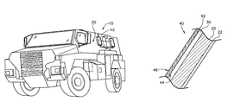
- FIG. 1is a schematic image of a perspective view of the vehicle armor according to an exemplary embodiment.
- FIG. 2is a schematic image of a detailed cross sectional view of the vehicle armor along line 2 - 2 according to the embodiment of FIG. 1 .
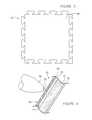
- FIG. 3is a schematic image of an elevation view of a portion of the vehicle armor according the embodiment of FIG. 1 .
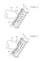
- FIG. 4is a schematic image of a detailed cross sectional view of the vehicle armor according to the embodiment of FIG. 2 upon impact by a projectile at a first stage.
- FIG. 5is a schematic image of a detailed cross sectional view of the vehicle armor according to the embodiment of FIG. 2 upon impact by a projectile at a second stage.
- FIG. 6is a schematic image of a detailed cross sectional view of the vehicle armor according to the embodiment of FIG. 2 upon impact by a projectile at a third stage.
- vehicle armore.g. shown for example as a lightweight vehicle armor system
- the armoris shown to include a “layered” or “laminate” type construction integrated with at least a portion of a body panel of the vehicle.
- An elastomer(such as a dense, particle-filled elastomer) is shown applied over an outer surface of the body panel and a single layer of thin steel tiles are applied over (and attached or adhered or bonded to) the elastomer.
- the single layer of thin steel tilesare formed having a first (outer) side that is surface hardened for fragmenting an impinging projectile and an second (inside) surface that is tough, energy-absorbing to permit deformation of the tile for impact energy absorption and distribution.
- the particle-filled elastomerprovides additional impact energy absorption and distribution.
- the body panel of the vehicleis shown and described by way of example to be formed as a “stressed skin” type construction from an aluminum alloy, and the thin steel tiles are shown to be formed from a single sheet (e.g. panel. etc.) of ductile low-carbon steel with one (outer) side carburized and the other (inner) side coated to prevent carburization and retain its toughness.
- the inventionis adaptable with any of a wide variety of body panel materials and constructions.
- any of a wide variety of interposing materials or bonding agents for coupling the tiles to the body panel and for absorbing or dissipating or distributing impact energymay be used.
- any of a wide variety of hardening techniques or proceduresmay be used to provide a thin steel tile with one side having a ductile or tough region and the other side having a hardened region.
- Such variations and combinations thereofwill be readily apparent to a person of ordinary skill in the art after reviewing this disclosure. Accordingly, all such modifications and variations are intended to be within the scope of the invention.
- Vehicle 10includes a body 20 (e.g. shell, structure, panels, sheets, etc.) constructed (for example) using a stressed skin type construction comprising aluminum alloy sheets, forgings and/or castings that may assembled together using any suitable technique, such as friction-stir-welding (FSW).
- FSWfriction-stir-welding
- the FSW techniqueis intended to enable the use of alloys having high dynamic tensile strength whose composition and heat treatment might otherwise render the parts difficult to weld together with adequate joint integrity and without subsequent heat treatment of the welded assembly.
- the stressed skin structuremay form most or all of the body of the vehicle, or may be provided as multiple modular sections which, when connected to other modular section(s), will combine to provide a substantially complete assembly for a body of the vehicle.
- the aluminum alloy materialis AA5083 per MIL-DTL-46027.
- the body portionmay be formed from a 7000 heat treated series aluminum or any other suitable material, including but not limited to a MIL-A-46177 steel, stainless steel, titanium, etc.
- the vehicle armoris integrated with the body 20 , and includes the body 20 , and a layer of bonding agent 30 (such as a dense, particle-filled elastomer), and a layer of armor applied over the elastomer 30 .
- the thickness of the aluminum structure of the body 20is generally defined by its ability to react to the static and dynamic loadings to which it is subjected during operation of the vehicle 10 . These loadings include those arising from acceleration and mobility over severe off-road terrain, forces due to static or quasi-static loadings, forces encountered during transportation, and forces due to blast and projectile type impacts. According to one embodiment, a thickness of the body is within a range of approximately 0.25 to 3.0 inches.
- the layer of armor 40is formed as a single layer from a series of individual tiles 42 according to an exemplary embodiment.
- the tiles 42are relatively thin tiles intended to minimize the additional weight imposed on the vehicle by the armor.
- a thickness of the tilesis within a range of approximately 0.08 to 0.75 inches.
- the tiles of the present embodimentare formed from a low-carbon steel in a suitable size such that distortions due to the tile's subsequent heat treatment will have a negligible effect on the vehicle's manufacturing process, or the detectable radar reflectivity of the outer surface of the tiles.
- the tilesare made of a tough, low-carbon steel plate that will not harden when heated to red heat and quenched in water or oil.
- Such a steelcan be that known as “Domex” which has a nominal carbon content of approximately 0.17% and a nominal yield strength of approximately 115 ksi.
- Other similar steel alloysmay also be suitable.
- steel alloys having a nominal carbon weight percentage within a range of approximately 0.05% to 0.32%, and a nominal yield strength within the range of 80 to 150 ksimay also be used to create a tile that integrates one hardened side/region with an opposite tough, energy-absorbing side/region in a single plate intended to minimize weight, reduce cost, simplify manufacturing operations, and meet the desired protection performance from the impact energy of blast and projectile type threats.
- the typical shape or plan form of an exemplary tile 42is shown as generally planar and square or rectangular, where the outer perimeter edges are shaped to couple or interlock with each other in a “jigsaw” like manner.
- the tileshave a height and width within the range of approximately 1 to 60 inches.
- the tilesmay have any of a wide variety of shapes (e.g. circular, triangular, pentagonal, hexagonal, octagonal, etc.), and may be convex, concave, or contoured in any suitable manner to conform to the outside shape of the body portion, or to enhance the space between the tiles and the body portion for increased energy absorption, distribution, and/or dissipation.
- the tilesmay also have any suitable size and may interface with one another in any suitable manner, such as mating projections and recesses, or may simply have a generally smooth interface.
- the tiles 42are formed from plates of low-carbon steel having the desired toughness properties (as previously described) for use on an inner side/region of the tile 42 .
- the tiles 42are then transformed by a manufacturing processes into a single tile that retains the original characteristics of a tough (non-hardened) inner side/region 44 and forms a hardened outer side/region 46 .
- the low-carbon steel tilesare hardened on the outer side 46 only, through a diffusion hardening process to produce a single layer tile 42 that integrates one hardened outer side/region 46 with an opposite (non-hardened) inner side/region 44 that remains tough and energy-absorbing.
- the diffusion hardening processmay include (among others) carburization, where the tile 42 may be carburized on only one side 46 by temporarily coating the inner (i.e. tough) side 44 of the tile with a masking material suitable to prevent carburization (or other diffusion hardening) of the tile during a diffusion hardening (e.g. carburizing, etc.) operation on the entire tile (e.g. in the manner of a “stop coat” or the like on side 44 of the plate only).
- the stop coatmay be applied by coating or plating (e.g. copper plating, etc.) the entire tile 42 and then etching, or otherwise removing the plating from the exposed (outer) side 46 of the tile to be hardened.
- the tile 42 so treatedmay then be carburized to transform the exposed side 46 of the tile into a high-carbon steel alloy to a suitable depth.
- the hardening processmay be conducted by any of a variety of suitable processes.
- hardening of the outer side/region of the tilemay be accomplished by carbonitriding, nitrocarburizing, or other surface hardening process.
- the outer surface 46 of tile 42may be boronized by any one of several processes.
- boronizinge.g. boriding, etc. is a thermochemical process in which boron atoms from a solid, liquid, gas, or plasma atmosphere surrounding the tile are diffused into the outer surface region 46 of tile 42 , creating a hard, outer iron boride layer.
- the result of the process according to the exemplary embodimentis a single-layer, relatively thin, steel tile with an exceptionally hard exposed outer face/region that is integral with a tough, but non-brittle, steel inner substrate/region.
- the armor tiles 42are coupled (e.g. attached, bonded, joined, adhered, etc.) to the body 20 by the interposed elastomer bonding agent 30 .
- the density of elastomer 30may be significantly increased by filling it with heavy metallic particles such as iron; steel or tungsten (among others).
- the thickness, density and shear characteristics of the elastomer layerare selected to absorb the shock of impact and to spread the load imparted to the body over a wider area.
- the elastomeris hydraulically incompressible and is vulcanized or adhesively bonded to the tile to maximize the absorption and redirect the energy of a ballistic event.
- the hardened outer side/region 46 of the tiles 42serves to deflect and/or shatter the hardened point 52 of an impinging projectile 50 (such as a ballistic projectile as shown in FIG. 4 , or a fragmentary projectile such as shrapnel, etc.).
- the tough inner tile side/region 44is shown to deflect inward elastically and displaces the elastomer 30 , which is hydraulically incompressible, laterally and radially outwards from the point of impact, thus absorbing impact energy (see FIGS. 5 and 6 ).
- a thin layer 48 of the hardened, brittle outer surface 46spalls free of the main body of the tile 42 by shearing laterally through the hardened outer side/region 46 , to leave a rough exposed hard subsurface to abrade and continue to break-up the projectile 50 .
- the inner side 44 of the tile 42stretches elastically inward, it continues to displace the high-density elastomer 30 laterally outwards away from the point of impact, further dissipating energy from the projectile.
- inner side 44 of the steel tile 42reaches its rupture stress, it physically contacts the body 20 to react the impact force from the projectile over a larger area.
- a tough, durable materialfor example an aramide fiber material, such as those commercially available under the trademark Kevlar® may be affixed to the inner face of the body 20 to prevent spall injury to the vehicle's occupants or spall damage to the vehicle's systems.
- the lightweight vehicle armor systemprovides a single-layer, relatively thin, carbon steel tile having a hardened outer surface and a non-hardened tough, energy-absorbing inner surface bonded by a high-density, particle-filled elastomer layer to a body portion of a vehicle.
- the body portionis preferably a stressed skin type construction comprising panels and components made from an aluminum alloy that are joined by a friction-stir-welding process.
- a spall linermay also be provided along all (or a portion) of the inside surface of the vehicle body.
- the tilemay be manufactured from a ductile or tough low-carbon steel plate that is surface hardened, e.g.
- the elastomeris preferably a hydraulically incompressible, high-density bonding agent that may be filled with particles to provide the desired shear and flow characteristics for bonding the tiles to the body portion and absorbing and dissipating impact energy from a blast or projectile.
- elastomer 30may include piezoelectric capabilities, enabling the elastomer to adapt to any one of a variety of different performance characteristics through control of an electric field.
- any means-plus-function clauseis intended to cover the structures described herein as performing the recited function and not only structural equivalents but also equivalent structures.
- Other substitutions, modifications, changes and omissionsmay be made in the design, operating configuration and arrangement of the preferred and other exemplary embodiments without departing from the spirit of the present invention as expressed in the appended claims.
Landscapes
- Engineering & Computer Science (AREA)
- Ceramic Engineering (AREA)
- General Engineering & Computer Science (AREA)
- Aiming, Guidance, Guns With A Light Source, Armor, Camouflage, And Targets (AREA)
- Laminated Bodies (AREA)
Abstract
Description
Claims (7)
Priority Applications (1)
| Application Number | Priority Date | Filing Date | Title |
|---|---|---|---|
| US11/880,739US7963204B2 (en) | 2007-07-24 | 2007-07-24 | Stressed skin tiled vehicle armor |
Applications Claiming Priority (1)
| Application Number | Priority Date | Filing Date | Title |
|---|---|---|---|
| US11/880,739US7963204B2 (en) | 2007-07-24 | 2007-07-24 | Stressed skin tiled vehicle armor |
Publications (2)
| Publication Number | Publication Date |
|---|---|
| US20110120293A1 US20110120293A1 (en) | 2011-05-26 |
| US7963204B2true US7963204B2 (en) | 2011-06-21 |
Family
ID=44061107
Family Applications (1)
| Application Number | Title | Priority Date | Filing Date |
|---|---|---|---|
| US11/880,739Active2029-11-10US7963204B2 (en) | 2007-07-24 | 2007-07-24 | Stressed skin tiled vehicle armor |
Country Status (1)
| Country | Link |
|---|---|
| US (1) | US7963204B2 (en) |
Cited By (11)
| Publication number | Priority date | Publication date | Assignee | Title |
|---|---|---|---|---|
| US20110167530A1 (en)* | 2009-03-31 | 2011-07-14 | Advanced Fuel Research, Inc. | High-strength porous carbon and its multifunctional applications |
| US20120186425A1 (en)* | 2008-11-24 | 2012-07-26 | Ideal Innovations, Inc. | Embedding particle armor for vehicles |
| US20120227578A1 (en)* | 2011-03-11 | 2012-09-13 | Stefan Klapyk | Bullet proof |
| US8991834B2 (en) | 2010-08-31 | 2015-03-31 | Oshkosh Defense, Llc | Gas spring assembly for a vehicle suspension system |
| US9581153B2 (en) | 2010-10-22 | 2017-02-28 | Oshkosh Corporation | Pump for vehicle suspension system |
| US9889633B2 (en) | 2014-04-10 | 2018-02-13 | Honda Motor Co., Ltd. | Attachment method for laminate structures |
| US10221055B2 (en) | 2016-04-08 | 2019-03-05 | Oshkosh Corporation | Leveling system for lift device |
| US10495419B1 (en) | 2017-04-27 | 2019-12-03 | Oshkosh Defense, Llc | Vehicle armor systems and methods |
| US10843379B2 (en) | 2017-09-25 | 2020-11-24 | Oshkosh Corporation | Mixing drum |
| US12098757B1 (en) | 2013-03-10 | 2024-09-24 | Oshkosh Defense, Llc | Limiting system for a vehicle suspension component |
| US12441151B1 (en) | 2024-09-16 | 2025-10-14 | Oshkosh Defense, Llc | Gas spring assembly for a vehicle suspension system |
Families Citing this family (3)
| Publication number | Priority date | Publication date | Assignee | Title |
|---|---|---|---|---|
| EP2427717B1 (en)* | 2009-05-05 | 2014-12-03 | Bell Helicopter Textron Inc. | Method for analyzing and designing armor in a vehicle |
| EP2538167A1 (en)* | 2011-06-23 | 2012-12-26 | Nederlandse Organisatie voor toegepast -natuurwetenschappelijk onderzoek TNO | Blast and fragment resistant wall sections used inside structures like ships |
| US11359393B2 (en) | 2019-03-25 | 2022-06-14 | Oshkosh Corporation | Systems and methods for additive manufacturing |
Citations (29)
| Publication number | Priority date | Publication date | Assignee | Title |
|---|---|---|---|---|
| US2102963A (en)* | 1936-05-28 | 1937-12-21 | Miller George Lee | Manufacture of armor plates |
| US2201202A (en)* | 1938-12-15 | 1940-05-21 | Everett L Reed | Armor plate |
| USRE22072E (en)* | 1942-04-14 | Allot steel | ||
| US2342104A (en)* | 1942-02-05 | 1944-02-22 | Du Pont | Manufacture of light armor plate |
| US3157090A (en) | 1961-02-09 | 1964-11-17 | Ballu Louis Henri Denys Marie | Armor plate |
| US4040333A (en)* | 1976-10-18 | 1977-08-09 | General Dynamics | Isogrid shell gun mount |
| US4090011A (en) | 1964-07-02 | 1978-05-16 | Reynolds Metals Company | Armor |
| US4100860A (en)* | 1971-08-13 | 1978-07-18 | Nuclear Engineering Co., Inc. | Safe transporation of hazardous materials |
| US4232069A (en)* | 1979-04-16 | 1980-11-04 | International Harvester Company | Impact resistant composite structure |
| DE3716055A1 (en) | 1987-05-14 | 1988-12-01 | Diehl Gmbh & Co | Passive armour against hard-core munition |
| US4879165A (en)* | 1988-06-20 | 1989-11-07 | Smith W Novis | Lightweight armor |
| US4923741A (en)* | 1988-06-30 | 1990-05-08 | The United States Of America As Represented By The Administrator, National Aeronautics And Space Administration | Hazards protection for space suits and spacecraft |
| US4953442A (en)* | 1986-01-07 | 1990-09-04 | Harsco Corporation | Magnetized ceramic armor system |
| US5170690A (en)* | 1988-06-03 | 1992-12-15 | Foster-Miller, Inc. | Survivability enhancement |
| US5190802A (en)* | 1989-01-06 | 1993-03-02 | Pilato Louis A | Ballistic resistant laminate |
| GB2260600A (en) | 1991-10-16 | 1993-04-21 | Wahl Verschleiss Tech | Armour plate |
| WO1993021492A1 (en) | 1992-04-14 | 1993-10-28 | Kim Patchett | Armour tiles and flexible armour composed of such tiles |
| US5312693A (en)* | 1986-05-28 | 1994-05-17 | The United States Of America As Represented By The Secretary Of The Air Force | Nonsacrificial laser hardening |
| US5333532A (en) | 1988-06-03 | 1994-08-02 | Foster-Miller, Inc. | Survivability enhancement |
| WO1994024894A1 (en) | 1993-05-05 | 1994-11-10 | Kim Patchett | Flexible sheet material |
| US5402730A (en) | 1993-08-11 | 1995-04-04 | The Walt Disney Company | Platen drive unit |
| US5443917A (en)* | 1991-05-24 | 1995-08-22 | Gte Products Corporation | Ceramic armor |
| US6205728B1 (en)* | 1997-04-30 | 2001-03-27 | Frank Sutelan | Laminated composite building component |
| US6327954B1 (en)* | 1993-06-03 | 2001-12-11 | Richard C. Medlin | Lightweight armored vehicle and method of making same |
| US7383761B2 (en)* | 2004-12-08 | 2008-06-10 | Armordynamics, Inc. | Methods and apparatus for providing ballistic protection |
| US20080282876A1 (en)* | 2005-05-23 | 2008-11-20 | Oztech Pty Ltd. | Pressure Impulse Mitigation |
| US20090178597A1 (en)* | 2004-12-14 | 2009-07-16 | Sliwa Jr John W | Physical threat containment, neutralization and protection means applicable to terrorism, combat and disaster mitigation |
| US20100005955A1 (en)* | 2005-04-12 | 2010-01-14 | Mjd Innovations, L.L.C. | Body armor structure, method and performance |
| US20100043630A1 (en)* | 2006-12-04 | 2010-02-25 | Jay Sayre | Composite Armor and Method for Making Composite Armor |
- 2007
- 2007-07-24USUS11/880,739patent/US7963204B2/enactiveActive
Patent Citations (30)
| Publication number | Priority date | Publication date | Assignee | Title |
|---|---|---|---|---|
| USRE22072E (en)* | 1942-04-14 | Allot steel | ||
| US2102963A (en)* | 1936-05-28 | 1937-12-21 | Miller George Lee | Manufacture of armor plates |
| US2201202A (en)* | 1938-12-15 | 1940-05-21 | Everett L Reed | Armor plate |
| US2342104A (en)* | 1942-02-05 | 1944-02-22 | Du Pont | Manufacture of light armor plate |
| US3157090A (en) | 1961-02-09 | 1964-11-17 | Ballu Louis Henri Denys Marie | Armor plate |
| US4090011A (en) | 1964-07-02 | 1978-05-16 | Reynolds Metals Company | Armor |
| US4100860A (en)* | 1971-08-13 | 1978-07-18 | Nuclear Engineering Co., Inc. | Safe transporation of hazardous materials |
| US4040333A (en)* | 1976-10-18 | 1977-08-09 | General Dynamics | Isogrid shell gun mount |
| US4232069A (en)* | 1979-04-16 | 1980-11-04 | International Harvester Company | Impact resistant composite structure |
| US4953442A (en)* | 1986-01-07 | 1990-09-04 | Harsco Corporation | Magnetized ceramic armor system |
| US5312693A (en)* | 1986-05-28 | 1994-05-17 | The United States Of America As Represented By The Secretary Of The Air Force | Nonsacrificial laser hardening |
| DE3716055A1 (en) | 1987-05-14 | 1988-12-01 | Diehl Gmbh & Co | Passive armour against hard-core munition |
| US5170690A (en)* | 1988-06-03 | 1992-12-15 | Foster-Miller, Inc. | Survivability enhancement |
| US5333532A (en) | 1988-06-03 | 1994-08-02 | Foster-Miller, Inc. | Survivability enhancement |
| US4879165A (en)* | 1988-06-20 | 1989-11-07 | Smith W Novis | Lightweight armor |
| US4923741A (en)* | 1988-06-30 | 1990-05-08 | The United States Of America As Represented By The Administrator, National Aeronautics And Space Administration | Hazards protection for space suits and spacecraft |
| US5190802A (en)* | 1989-01-06 | 1993-03-02 | Pilato Louis A | Ballistic resistant laminate |
| US5443917A (en)* | 1991-05-24 | 1995-08-22 | Gte Products Corporation | Ceramic armor |
| GB2260600A (en) | 1991-10-16 | 1993-04-21 | Wahl Verschleiss Tech | Armour plate |
| WO1993021492A1 (en) | 1992-04-14 | 1993-10-28 | Kim Patchett | Armour tiles and flexible armour composed of such tiles |
| WO1994024894A1 (en) | 1993-05-05 | 1994-11-10 | Kim Patchett | Flexible sheet material |
| US6327954B1 (en)* | 1993-06-03 | 2001-12-11 | Richard C. Medlin | Lightweight armored vehicle and method of making same |
| US5402730A (en) | 1993-08-11 | 1995-04-04 | The Walt Disney Company | Platen drive unit |
| US6205728B1 (en)* | 1997-04-30 | 2001-03-27 | Frank Sutelan | Laminated composite building component |
| US7383761B2 (en)* | 2004-12-08 | 2008-06-10 | Armordynamics, Inc. | Methods and apparatus for providing ballistic protection |
| US7628104B2 (en)* | 2004-12-08 | 2009-12-08 | Armordynamics, Inc. | Methods and apparatus for providing ballistic protection |
| US20090178597A1 (en)* | 2004-12-14 | 2009-07-16 | Sliwa Jr John W | Physical threat containment, neutralization and protection means applicable to terrorism, combat and disaster mitigation |
| US20100005955A1 (en)* | 2005-04-12 | 2010-01-14 | Mjd Innovations, L.L.C. | Body armor structure, method and performance |
| US20080282876A1 (en)* | 2005-05-23 | 2008-11-20 | Oztech Pty Ltd. | Pressure Impulse Mitigation |
| US20100043630A1 (en)* | 2006-12-04 | 2010-02-25 | Jay Sayre | Composite Armor and Method for Making Composite Armor |
Cited By (24)
| Publication number | Priority date | Publication date | Assignee | Title |
|---|---|---|---|---|
| US20120186425A1 (en)* | 2008-11-24 | 2012-07-26 | Ideal Innovations, Inc. | Embedding particle armor for vehicles |
| US8615812B2 (en)* | 2009-03-31 | 2013-12-31 | Advanced Fuel Research, Inc. | High-strength porous carbon and its multifunctional applications |
| US20110167530A1 (en)* | 2009-03-31 | 2011-07-14 | Advanced Fuel Research, Inc. | High-strength porous carbon and its multifunctional applications |
| US9688112B2 (en) | 2010-08-31 | 2017-06-27 | Oshkosh Defense, Llc | Gas spring assembly for a vehicle suspension system |
| US8991834B2 (en) | 2010-08-31 | 2015-03-31 | Oshkosh Defense, Llc | Gas spring assembly for a vehicle suspension system |
| US11225120B2 (en) | 2010-08-31 | 2022-01-18 | Oshkosh Defense, Llc | Gas spring assembly for a vehicle suspension system |
| US12115826B2 (en) | 2010-08-31 | 2024-10-15 | Oshkosh Defense, Llc | Gas spring assembly for a vehicle suspension system |
| US10421332B2 (en) | 2010-08-31 | 2019-09-24 | Oshkosh Defense, Llc | Gas spring assembly for a vehicle suspension system |
| US11225119B2 (en) | 2010-08-31 | 2022-01-18 | Oshkosh Defense, Llc | Gas spring assembly for a vehicle suspension system |
| US9581153B2 (en) | 2010-10-22 | 2017-02-28 | Oshkosh Corporation | Pump for vehicle suspension system |
| US20120227578A1 (en)* | 2011-03-11 | 2012-09-13 | Stefan Klapyk | Bullet proof |
| US12098757B1 (en) | 2013-03-10 | 2024-09-24 | Oshkosh Defense, Llc | Limiting system for a vehicle suspension component |
| US9889633B2 (en) | 2014-04-10 | 2018-02-13 | Honda Motor Co., Ltd. | Attachment method for laminate structures |
| US10934145B2 (en) | 2016-04-08 | 2021-03-02 | Oshkosh Corporation | Leveling system for lift device |
| US11565920B2 (en) | 2016-04-08 | 2023-01-31 | Oshkosh Corporation | Leveling system for lift device |
| US11679967B2 (en) | 2016-04-08 | 2023-06-20 | Oshkosh Corporation | Leveling system for lift device |
| US12091298B2 (en) | 2016-04-08 | 2024-09-17 | Oshkosh Corporation | Leveling system for lift device |
| US10221055B2 (en) | 2016-04-08 | 2019-03-05 | Oshkosh Corporation | Leveling system for lift device |
| US11181345B2 (en) | 2017-04-27 | 2021-11-23 | Oshkosh Defense, Llc | Vehicle armor systems and methods |
| US12025411B2 (en) | 2017-04-27 | 2024-07-02 | Oshkosh Defense, Llc | Vehicle armor systems and methods |
| US10495419B1 (en) | 2017-04-27 | 2019-12-03 | Oshkosh Defense, Llc | Vehicle armor systems and methods |
| US10843379B2 (en) | 2017-09-25 | 2020-11-24 | Oshkosh Corporation | Mixing drum |
| US11999078B2 (en) | 2017-09-25 | 2024-06-04 | Oshkosh Corporation | Mixing drum |
| US12441151B1 (en) | 2024-09-16 | 2025-10-14 | Oshkosh Defense, Llc | Gas spring assembly for a vehicle suspension system |
Also Published As
| Publication number | Publication date |
|---|---|
| US20110120293A1 (en) | 2011-05-26 |
Similar Documents
| Publication | Publication Date | Title |
|---|---|---|
| US7963204B2 (en) | Stressed skin tiled vehicle armor | |
| US5905225A (en) | Armouring | |
| US6497966B2 (en) | Laminated armor | |
| US6216579B1 (en) | Composite armor material | |
| US8151685B2 (en) | Apparatus for defeating high energy projectiles | |
| CN103180685B (en) | There is the armour plate of bar shaped protection element and absorb the method for bullet energy | |
| US20100319525A1 (en) | System and Method for Protecting Vehicle Occupants | |
| US20110083549A1 (en) | Multi-Functional Armor System | |
| US20100212486A1 (en) | Ballistic armor panel system | |
| AU2002223998A1 (en) | Laminated armor | |
| US8468926B2 (en) | Ballistic armor system | |
| US9835419B2 (en) | Method and system for armored energy-dispersion objects | |
| US7543523B2 (en) | Antiballistic armor | |
| US4869152A (en) | Combined active and passive armor system | |
| US9091509B2 (en) | Armor assembly | |
| US8418597B2 (en) | System and method for protecting vehicle occupants | |
| US8336439B2 (en) | Layering non-metallic layers between metallic layers to improve armor protection | |
| GB2475418A (en) | Armour plate component | |
| WO2009096956A1 (en) | Protective armor structure | |
| TW200940945A (en) | Apparatus for defeating high energy projectiles | |
| Tsirogiannis et al. | Composite armor philosophy (CAP): Holistic design methodology of multi-layered composite protection systems for armored vehicles | |
| KR20170081870A (en) | Lightweight Armor | |
| US20120186432A1 (en) | Layering of Air Gaps To Improve Armor Protection | |
| US20120186431A1 (en) | Armor System Comprising Dilatant Material To Improve Armor Protection | |
| GB2191277A (en) | Composite armour |
Legal Events
| Date | Code | Title | Description |
|---|---|---|---|
| AS | Assignment | Owner name:OSHKOSH TRUCK CORPORATION, WISCONSIN Free format text:ASSIGNMENT OF ASSIGNORS INTEREST;ASSIGNORS:VENTON-WALTERS, ROY;HATHAWAY, ROBERT M.;REEL/FRAME:019660/0399 Effective date:20070720 | |
| AS | Assignment | Owner name:OSHKOSH CORPORATION, WISCONSIN Free format text:CHANGE OF NAME;ASSIGNOR:OSHKOSH TRUCK CORPORATION;REEL/FRAME:026264/0576 Effective date:20080205 | |
| STCF | Information on status: patent grant | Free format text:PATENTED CASE | |
| FEPP | Fee payment procedure | Free format text:PAYOR NUMBER ASSIGNED (ORIGINAL EVENT CODE: ASPN); ENTITY STATUS OF PATENT OWNER: LARGE ENTITY | |
| FPAY | Fee payment | Year of fee payment:4 | |
| MAFP | Maintenance fee payment | Free format text:PAYMENT OF MAINTENANCE FEE, 8TH YEAR, LARGE ENTITY (ORIGINAL EVENT CODE: M1552); ENTITY STATUS OF PATENT OWNER: LARGE ENTITY Year of fee payment:8 | |
| MAFP | Maintenance fee payment | Free format text:PAYMENT OF MAINTENANCE FEE, 12TH YEAR, LARGE ENTITY (ORIGINAL EVENT CODE: M1553); ENTITY STATUS OF PATENT OWNER: LARGE ENTITY Year of fee payment:12 |