US7962230B2 - System including at least one automation unit - Google Patents
System including at least one automation unitDownload PDFInfo
- Publication number
- US7962230B2 US7962230B2US12/225,621US22562107AUS7962230B2US 7962230 B2US7962230 B2US 7962230B2US 22562107 AUS22562107 AUS 22562107AUS 7962230 B2US7962230 B2US 7962230B2
- Authority
- US
- United States
- Prior art keywords
- automation
- operation program
- unit
- data structure
- modified
- Prior art date
- Legal status (The legal status is an assumption and is not a legal conclusion. Google has not performed a legal analysis and makes no representation as to the accuracy of the status listed.)
- Active, expires
Links
- 238000004891communicationMethods0.000claimsabstractdescription36
- 238000000034methodMethods0.000claimsdescription34
- 230000008569processEffects0.000description14
- 230000004048modificationEffects0.000description9
- 238000012986modificationMethods0.000description9
- 238000012546transferMethods0.000description6
- 230000004913activationEffects0.000description2
- 230000008901benefitEffects0.000description2
- 238000009434installationMethods0.000description2
- 238000004088simulationMethods0.000description2
- 230000000977initiatory effectEffects0.000description1
- 230000007257malfunctionEffects0.000description1
- 230000007246mechanismEffects0.000description1
- 238000012545processingMethods0.000description1
Images


Classifications
- G—PHYSICS
- G05—CONTROLLING; REGULATING
- G05B—CONTROL OR REGULATING SYSTEMS IN GENERAL; FUNCTIONAL ELEMENTS OF SUCH SYSTEMS; MONITORING OR TESTING ARRANGEMENTS FOR SUCH SYSTEMS OR ELEMENTS
- G05B19/00—Programme-control systems
- G05B19/02—Programme-control systems electric
- G05B19/04—Programme control other than numerical control, i.e. in sequence controllers or logic controllers
- G05B19/05—Programmable logic controllers, e.g. simulating logic interconnections of signals according to ladder diagrams or function charts
- G05B19/056—Programming the PLC
- G—PHYSICS
- G05—CONTROLLING; REGULATING
- G05B—CONTROL OR REGULATING SYSTEMS IN GENERAL; FUNCTIONAL ELEMENTS OF SUCH SYSTEMS; MONITORING OR TESTING ARRANGEMENTS FOR SUCH SYSTEMS OR ELEMENTS
- G05B2219/00—Program-control systems
- G05B2219/10—Plc systems
- G05B2219/13—Plc programming
- G05B2219/13153—Modification, change of program in real time
Definitions
- the inventionrefers to a control and communication system including at least one automation unit being adapted to run an operation program, and an engineering unit being adapted to modify the operation program. Further, the invention refers to a method of modifying an operation program of at least one automation unit of a control and communication system, the control and communication system further including an engineering unit being adapted to modify the operation program of the corresponding automation unit.
- a control and communication systemincluding at least one automation unit being adapted to run an operation program, and an engineering unit being adapted to modify the operation program, the engineering unit including a code-configurator, which is adapted to project automation functions of the operation program in the form of at least one configured data structure and to modify the configured data structure, the at least one automation unit including an interpreter framework, which is adapted to include a catalogue of predefined, necessary automation functions of the operation program and an empty data structure, the interpreter framework being further adapted to interpret the modified configured data structure and to provide a modified operation program on the basis of at least one of the automation functions of said catalogue and the modified configured data structure.
- the configured data structurein particular contain pointers and values and is used in the interpreter framework to point at the relevant automation functions (already provided in the said catalogue of the interpreter framework) and to fill them with the appropriate values.
- the inventionprovides a projection of automation functions of an automation unit in the form of at least one configured data structure.
- This data structurejust contains data, but no functions in the common form.
- the configured data structureis interpreted at the automation unit by assigning corresponding automation functions from a catalogue of automation functions, which was previously included at the automation unit.
- the inventionenables a modification of projected automation functions at automation units, which achieves very short times required for generating and downloading of the modifications.
- the solution according to the inventionparticularly suitable for control and communication systems of plants, such as power plants, in which the at least one automation unit and the engineering unit are each connected to a common communication bus of a peer-to-peer communication network.
- the engineering unitis adapted to send the at least one modified configured data structure to the at least one automation unit by means of the corresponding interpreter framework.
- the interpreter frameworkadditionally provides the functions of an interface between the engineering unit and the corresponding automation unit.
- the engineering unitis adapted to include a structural image of the operation system of the at least one automation unit.
- the structural imagemay serve as a basis for the projection of automation functions of the operation program of the corresponding automation unit in the form of said at least one configured data structure.
- the at least one automation unitis advantageously adapted to switch to the modified operation program while keeping the previous running operation program in a corresponding buffer.
- the modified configured data structureis kept in a corresponding buffer of the engineering unit or the corresponding automation unit.
- the at least one automation unitfurther advantageously includes a running operation program and is adapted to switch to the modified operation program while running said operation system.
- the object of the inventionis further solved by a method of modifying an operation program of an automation unit of a control and communication system, the control and communication system further including an engineering unit being adapted to modify the operation program, the method including the steps of projecting automation functions of the operation program in the form of at least one configured data structure and modifying the configured data structure in the engineering unit, providing a catalogue of predefined, necessary automation functions of the operation program and an empty data structure in the at least one automation unit, sending the modified configured data structure to the at least one automation unit, interpreting the modified configured data structure at the at least one automation unit, and providing a modified operation program at the at least one automation unit on the basis of at least one of the automation functions of said catalogue and the modified configured data structure.
- said methodincludes the step of sending the modified configured data structure to the at least one automation unit by means of the automation functions provided in the corresponding automation unit.
- said methodincludes the step of including a structural image of the operation system of the at least one automation unit in the engineering unit.
- the method according to the inventionincludes the step of switching to the modified operation program in the at least one automation unit while keeping the previous running operation program in a corresponding buffer.
- said methodincludes the step of running an operation program in the at least one automation unit and switching to the modified operation program while running said operation system.
- a shock-free modification of operation programs in running automation unitscan be provided, i.e., the modification can be done without interruption or impact on the running process.
- New functionscan be added to the process, internal switchings and parameters can be amended, and functions can be moved to other program cycles.
- Short “turnarounds” or switching timescan be achieved for providing the modified operation program in the corresponding automation unit in an executable manner.
- the previous operation programcan be rebuild or restored in a shock-free manner after modifications had been made on the basis of the modified configured data structure. It is only necessary to switch to the old data structure, which points to the previous automation functions and includes values for the previous operation program.
- the solution of the inventionfurther enables a simulation of any user-defined input and/or output values in process circuitry without loosing the possibility to display the actual process value of the equipment.
- the user defined valuemay be inserted in the configured data structure instead of the actual process value and may thus form the basis for a simulation of such value in the following automation function.
- a consistency checkmay be provided on the basis of the solution according to the invention, which allows to find inconsistencies, e.g. because of communication malfunctions or manually made amendments, before placing the projected modifications into the corresponding automation unit.
- the inventionprovides the basis for an automatic dispatching of automation functions in corresponding timeframes, in order to receive a balanced processor load of the automation units for the different and various operation cycles.
- the communication between the engineering unit and the interpreter framework of the at least one automation unit according to the inventionmay further be used for a kind of integrated communication mechanism which allows to exchange process signals (in particular for operation of the automation units and/or for human/machine interfaces (hmi)) even across several automation units without needing an additional projection of such signal transfers.
- said communicationmay be used for an integrated alarm handling of binary output signals without any additional circuit.
- the binary output signalsmay simply be addressed by an appropriate automation function which is to be included in the interpreter framework and may be paged thereafter by a corresponding pointer in the configured data structure of the engineering unit.
- the solution according to the inventionmay provide an integrated quality code for each signal, in that the configured data structure does not only address a particular automation function but does further provide quality data for the corresponding signal which are used in the automation function for a quality check.
- a completely new operation systemwas configured in the automation unit and a corresponding code generator was developed in the engineering unit.
- the projected automation functionsare entirely described in the form of data, a time consuming generating of functions is not necessary.
- the automation unitinterprets the configured data structures. The interpretation of the operation structures forms the core or basis for the realisation of functions of the operation program.
- the engineering systemparticularly receives a complete image of the operation structures deposited in the automation unit and configures the necessary data structures in the case of an activated projecting modification. Thereby all necessary amendments are transferred to the automation unit in parallel to the running operation program. Upon consistent and complete transfer of all data, the engineering unit will switch the automation unit to the modified operation structure. In this way a negative impact on the running operation program can be ruled out.
- the interpreter frameworkis loaded once at the initialisation of the automation unit and provides its services thereafter.
- the engineering unituses the services of the interpreter framework for the transfer of the configured projecting data, thereby defining the functioning of the interpreter framework.
- the interpreter frameworkincludes all necessary functions and also the empty data structures, an extensive loading of further data components during activation of the projecting structures is not needed.
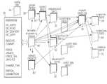
- FIG. 1shows a diagrammatic depiction of an embodiment of a control and communication system according to the invention
- FIGS. 2 a and 2 bshow a first list of telegrams or jobs which are exchangeable between partners of the control and communication system according to FIG. 1 ,
- FIGS. 3 a and 3 bshow a second list of telegrams or jobs which are exchangeable between the partners of the control and communication system according to FIG. 1 ,
- FIG. 4shows a third list of telegrams or jobs which are exchangeable between the partners of the control and communication system according to FIG. 1 ,
- FIG. 5shows a forth list of telegrams or jobs which are exchangeable between the partners of the control and communication system according to FIG. 1 ,
- FIG. 6shows a diagrammatic depiction of an embodiment of a method of modifying an operation program of an automation unit of a control and communication system according to FIG. 1 ,
- FIG. 7shows a diagrammatic depiction of the proceeding in the corresponding automation unit during the method according to FIG. 6 .
- FIG. 8shows a first diagrammatic depiction of the content of data components during the proceeding according to FIG. 7 .
- FIG. 9shows a second diagrammatic depiction of the content of data components during the proceeding according to FIG. 7 .
- FIG. 10shows a third diagrammatic depiction of the content of data components during the proceeding according to FIG. 7 and
- FIG. 11shows a diagrammatic depiction of the communication between the partners of the control and communication system according to FIG. 1 .
- FIG. 1a control and communication system 10 is shown, which includes an engineering unit 12 or server (Ft-server) and a number of automation units 14 in the form of SIMATIC S7 control units (only one is shown in FIG. 1 ).
- the engineering unit 12is operatively connected to the automation unit 14 via a peer-to-peer network 16 , wherein the communication includes four redundant channels 18 , 20 , 22 and 24 (channel-no. 0 , 1 , 2 , 3 ; redundance-no. 0 , 1 ).
- the units 12 and 14are thereby each addressed by means of IP-addresses (IP-adr.) and the channels 18 to 24 are accessible through appropriate ports (Port-no.) of the units 12 and 14 .
- IP-adr.IP-adr.
- the so called engineering-channelsignals, telegrams and/or jobs for the installation and modification of operation programs of the automation units 14 are transferred.
- the second channel 20serves for transferring signals, telegrams and/or jobs for the actual operation of the automation unit 14 .
- the third channel 22the so called hmi-channel, is used for a human/machine interface (hmi) between the engineering unit 12 and the corresponding automation unit 14 .
- the forth channel 24the so called alarm channel, provides alarm handling between the automation unit 14 and the engineering unit 12 .
- the channels 18 to 24provide a kind of integrated communication between the engineering unit 12 and the corresponding automation unit 14 , which allows to exchange process signals (in particular for modifying operation programs, for operation of the automation units, for human/machine interfaces (hmi) and/or for alarm signals) even across several automation units without needing an additional projection of such signal transfers.
- FIG. 2 a , 2 ba list of those signals 26 (in the form of telegrams or jobs) is shown, which are transferred between the engineering unit 12 (Ft-server) and the corresponding automation unit 14 (programmable logical controller, PLC) during the installation and modification of operation programs of the automation unit 14 .
- Ft-serverengineering unit 12
- PLCprogrammable logical controller
- the signals 26include, e.g., an initiation or activation of a new configuration of an automation program by means of a signal >>EXECUTE>>.
- the signalis confirmed by the automation unit 16 with a telegram acknowledgement via a signal ⁇ TEL_ACK ⁇ .
- the telegram acknowledgementserves a an integrated quality code for providing a quality check of the communication.
- FIGS. 3 a and 3 bshow a list of those signals 26 which are transferred between the engineering unit 12 and the corresponding automation unit 14 during the actual operation of the automation unit 14 .
- FIG. 4shows the corresponding human/machine interface signal transfer
- FIG. 5shows the signal transfer in the case of an alarm during operation.
- FIG. 6a diagrammatic partial depiction of the method of modifying an operation program of the automation unit 14 of the control and communication system 10 according to FIG. 1 is shown.
- the new or modified operation programis not developed in its entirety at the engineering unit 12 and is transferred to the automation unit 14 thereafter, but that it is developed in the form of a configured data structure including just pointers and values, but not entire functions.
- the pointers and valuesare interpreted by a interpreter framework, which forms a part of the automation unit 14 , but is not depicted in FIG. 6 in detail.
- FIG. 6just shows the processes of this interpretation of the configured data structure provided by the engineering unit 12 in principle.
- the engineering unit 12provides a number of data components (DB) at the interpreter framework of the automation unit 14 , in particular a Global DB 28 , a Cycle DB 30 , a number of Sequence DBs 32 , and a Module DB 34 .
- DBdata components
- the interpreter framework of the automation unit 14in particular a Global DB 28 , a Cycle DB 30 , a number of Sequence DBs 32 , and a Module DB 34 .
- DBdata components
- an actual module instanceis performed thereafter in a step 44 , using data from the Module DB 34 and providing outputs into Output DBs 46 (and an Instance DB).
- next steps 48 a , 48 b and 50 a , 50 bcheck whether the last module in the sequence list and/or the last Sequence DB 32 are reached and repeat the appropriate steps 38 to 44 , accordingly.
- the actual automation functions of the operation program of the automation unit 14are generated via an interpretation of the data structure of the data components 28 , 30 , 32 and 34 , which was provided (in a first-time or modified manner) by the engineering unit 12 .
- FIG. 7shows an above mentioned interpreter framework 52 in further details.
- the interpreter framework 52includes a process 54 (RCvSnd) for receiving and sending data to a telegram buffer 56 (TelBuff).
- the telegram buffer 56communicated with a process 58 (ProcEs) for processing engineering services.
- the process 58handles the actual reading and writing of data components, such as a Cycle DB 30 , a number of Sequence DBs 32 , and a number of Module DBs 34 .
- the process 58further addresses a number of Index DBs and a Force-DB 62 and writes data to the Output DBs 46 .
- the corresponding telegramsare received by the interpreter framework 52 over the engineering channel 18 and contain one or more jobs. These jobs are processed by the interpreter framework 52 . In errorless case a positive acknowledgement telegram is sent back.
- the answer for a signal or telegram DB_READis a DB_CONTENT telegram.
- FIG. 8 to FIG. 10are provided for further explaining the process of interpretation in the corresponding automation unit 14 .
- the processis based on a configuration data component 64 (config DB 1 ), which includes an individualizing RC number and a base cycle. These data are processed taking into account data from said Global DB 28 and the number of Cycle DBs 30 .
- the included dataare in particular information about the cycles to be processed and the sequences within the cycles.
- the traffic in the peer-to-peer networkis addressed via pear-to-peer (PtP) data components.
- the sequencesrefer via pointers (depicted by arrows) to modules of the Module DBs 34 , in which the actual instance data are stored.
- the catalogue of predefined necessary automation functions provided in the interpreter framework 52 in combination with the library of data components provided by the engineering unit 12is thus translated via said sequence date, said cycle data and said instance data to a running operation program which is stored in a output binary DB 66 , a output analogue DB 68 and an instance DB 70 .
Landscapes
- Physics & Mathematics (AREA)
- General Physics & Mathematics (AREA)
- Engineering & Computer Science (AREA)
- Automation & Control Theory (AREA)
- Programmable Controllers (AREA)
- Stored Programmes (AREA)
- Alarm Systems (AREA)
- Electroluminescent Light Sources (AREA)
- Computer And Data Communications (AREA)
Abstract
Description
This application is the US National Stage of International Application No. PCT/EP2007/052819, filed Mar. 23, 2007 and claims the benefit thereof. The International Application claims the benefits of German application No. 10 2006 015 161.5 filed Mar. 30, 2006, both of the applications are incorporated by reference herein in their entirety.
The invention refers to a control and communication system including at least one automation unit being adapted to run an operation program, and an engineering unit being adapted to modify the operation program. Further, the invention refers to a method of modifying an operation program of at least one automation unit of a control and communication system, the control and communication system further including an engineering unit being adapted to modify the operation program of the corresponding automation unit.
Automation of machinery equipment or plants, such as power plants, demands flexible and multi-purpose control and communication systems, in order to project the increasingly complex adjustment and control objects, in order to put them into operation and in order to adapt them to changing terms and conditions.
Although many efforts have been made in order to receive such control and communication systems, known systems are still considered to include too many inflexible rules and to be too complicated in programming and modifying of the corresponding operation programs.
Accordingly, it is an object of the present invention to provide a control and communication system and a method for modifying an operation program of such a system, which are much easier to amend. Meanwhile, the system and method have to keep the presently known low standard of error probability and it should be possible to provide the system and the method on the basis of presently known automation units, such as those of the well known SIMATIC family.
The object underlying the invention is solved by a control and communication system including at least one automation unit being adapted to run an operation program, and an engineering unit being adapted to modify the operation program, the engineering unit including a code-configurator, which is adapted to project automation functions of the operation program in the form of at least one configured data structure and to modify the configured data structure, the at least one automation unit including an interpreter framework, which is adapted to include a catalogue of predefined, necessary automation functions of the operation program and an empty data structure, the interpreter framework being further adapted to interpret the modified configured data structure and to provide a modified operation program on the basis of at least one of the automation functions of said catalogue and the modified configured data structure. The configured data structure in particular contain pointers and values and is used in the interpreter framework to point at the relevant automation functions (already provided in the said catalogue of the interpreter framework) and to fill them with the appropriate values.
In other words, the invention provides a projection of automation functions of an automation unit in the form of at least one configured data structure. This data structure just contains data, but no functions in the common form. The configured data structure is interpreted at the automation unit by assigning corresponding automation functions from a catalogue of automation functions, which was previously included at the automation unit. By doing so, the invention enables a modification of projected automation functions at automation units, which achieves very short times required for generating and downloading of the modifications.
The solution according to the invention particularly suitable for control and communication systems of plants, such as power plants, in which the at least one automation unit and the engineering unit are each connected to a common communication bus of a peer-to-peer communication network.
In a preferred embodiment of the invention, the engineering unit is adapted to send the at least one modified configured data structure to the at least one automation unit by means of the corresponding interpreter framework. Accordingly, the interpreter framework additionally provides the functions of an interface between the engineering unit and the corresponding automation unit.
Further preferred, the engineering unit is adapted to include a structural image of the operation system of the at least one automation unit. The structural image may serve as a basis for the projection of automation functions of the operation program of the corresponding automation unit in the form of said at least one configured data structure.
The at least one automation unit is advantageously adapted to switch to the modified operation program while keeping the previous running operation program in a corresponding buffer. Alternatively or additionally, the modified configured data structure is kept in a corresponding buffer of the engineering unit or the corresponding automation unit.
The at least one automation unit further advantageously includes a running operation program and is adapted to switch to the modified operation program while running said operation system.
The object of the invention is further solved by a method of modifying an operation program of an automation unit of a control and communication system, the control and communication system further including an engineering unit being adapted to modify the operation program, the method including the steps of projecting automation functions of the operation program in the form of at least one configured data structure and modifying the configured data structure in the engineering unit, providing a catalogue of predefined, necessary automation functions of the operation program and an empty data structure in the at least one automation unit, sending the modified configured data structure to the at least one automation unit, interpreting the modified configured data structure at the at least one automation unit, and providing a modified operation program at the at least one automation unit on the basis of at least one of the automation functions of said catalogue and the modified configured data structure.
In a first preferred embodiment, said method includes the step of sending the modified configured data structure to the at least one automation unit by means of the automation functions provided in the corresponding automation unit.
In a second preferred embodiment, said method includes the step of including a structural image of the operation system of the at least one automation unit in the engineering unit.
Further preferred, the method according to the invention includes the step of switching to the modified operation program in the at least one automation unit while keeping the previous running operation program in a corresponding buffer.
Also preferred, said method includes the step of running an operation program in the at least one automation unit and switching to the modified operation program while running said operation system.
By means of the solution according to the invention a shock-free modification of operation programs in running automation units can be provided, i.e., the modification can be done without interruption or impact on the running process. New functions can be added to the process, internal switchings and parameters can be amended, and functions can be moved to other program cycles.
Short “turnarounds” or switching times (according to the invention only some seconds are typical) can be achieved for providing the modified operation program in the corresponding automation unit in an executable manner.
At the automation unit even the previous operation program can be rebuild or restored in a shock-free manner after modifications had been made on the basis of the modified configured data structure. It is only necessary to switch to the old data structure, which points to the previous automation functions and includes values for the previous operation program.
The solution of the invention further enables a simulation of any user-defined input and/or output values in process circuitry without loosing the possibility to display the actual process value of the equipment. The user defined value may be inserted in the configured data structure instead of the actual process value and may thus form the basis for a simulation of such value in the following automation function.
A consistency check may be provided on the basis of the solution according to the invention, which allows to find inconsistencies, e.g. because of communication malfunctions or manually made amendments, before placing the projected modifications into the corresponding automation unit.
In addition, the invention provides the basis for an automatic dispatching of automation functions in corresponding timeframes, in order to receive a balanced processor load of the automation units for the different and various operation cycles.
The communication between the engineering unit and the interpreter framework of the at least one automation unit according to the invention may further be used for a kind of integrated communication mechanism which allows to exchange process signals (in particular for operation of the automation units and/or for human/machine interfaces (hmi)) even across several automation units without needing an additional projection of such signal transfers.
Further, said communication may be used for an integrated alarm handling of binary output signals without any additional circuit. The binary output signals may simply be addressed by an appropriate automation function which is to be included in the interpreter framework and may be paged thereafter by a corresponding pointer in the configured data structure of the engineering unit.
Finally, the solution according to the invention may provide an integrated quality code for each signal, in that the configured data structure does not only address a particular automation function but does further provide quality data for the corresponding signal which are used in the automation function for a quality check.
Thus, according to the invention a completely new operation system was configured in the automation unit and a corresponding code generator was developed in the engineering unit. The projected automation functions are entirely described in the form of data, a time consuming generating of functions is not necessary. The automation unit interprets the configured data structures. The interpretation of the operation structures forms the core or basis for the realisation of functions of the operation program.
The engineering system particularly receives a complete image of the operation structures deposited in the automation unit and configures the necessary data structures in the case of an activated projecting modification. Thereby all necessary amendments are transferred to the automation unit in parallel to the running operation program. Upon consistent and complete transfer of all data, the engineering unit will switch the automation unit to the modified operation structure. In this way a negative impact on the running operation program can be ruled out.
The interpreter framework is loaded once at the initialisation of the automation unit and provides its services thereafter. The engineering unit uses the services of the interpreter framework for the transfer of the configured projecting data, thereby defining the functioning of the interpreter framework. As the interpreter framework includes all necessary functions and also the empty data structures, an extensive loading of further data components during activation of the projecting structures is not needed.
A preferred embodiment of a control and communication system and a method of modifying an operation program of an automation unit of a control and communication system according to the invention is described hereinafter referring to the enclosed schematical drawings, in which:
InFIG. 1 a control andcommunication system 10 is shown, which includes anengineering unit 12 or server (Ft-server) and a number ofautomation units 14 in the form of SIMATIC S7 control units (only one is shown inFIG. 1 ). Theengineering unit 12 is operatively connected to theautomation unit 14 via a peer-to-peer network 16, wherein the communication includes fourredundant channels units channels 18 to24 are accessible through appropriate ports (Port-no.) of theunits
Via thefirst channel 18, the so called engineering-channel, signals, telegrams and/or jobs for the installation and modification of operation programs of theautomation units 14 are transferred. Thesecond channel 20, the so called operate-channel, serves for transferring signals, telegrams and/or jobs for the actual operation of theautomation unit 14. Thethird channel 22, the so called hmi-channel, is used for a human/machine interface (hmi) between theengineering unit 12 and thecorresponding automation unit 14. Finally, theforth channel 24, the so called alarm channel, provides alarm handling between theautomation unit 14 and theengineering unit 12.
As will be described in further detail hereinafter, thechannels 18 to24 provide a kind of integrated communication between theengineering unit 12 and thecorresponding automation unit 14, which allows to exchange process signals (in particular for modifying operation programs, for operation of the automation units, for human/machine interfaces (hmi) and/or for alarm signals) even across several automation units without needing an additional projection of such signal transfers.
InFIG. 2 a,2ba list of those signals26 (in the form of telegrams or jobs) is shown, which are transferred between the engineering unit12 (Ft-server) and the corresponding automation unit14 (programmable logical controller, PLC) during the installation and modification of operation programs of theautomation unit 14.
Thesignals 26 include, e.g., an initiation or activation of a new configuration of an automation program by means of a signal >>EXECUTE>>. The signal is confirmed by theautomation unit 16 with a telegram acknowledgement via a signal <<TEL_ACK<<. The telegram acknowledgement serves a an integrated quality code for providing a quality check of the communication.
InFIG. 6 a diagrammatic partial depiction of the method of modifying an operation program of theautomation unit 14 of the control andcommunication system 10 according toFIG. 1 is shown.
It is an important aspect of the method, that the new or modified operation program is not developed in its entirety at theengineering unit 12 and is transferred to theautomation unit 14 thereafter, but that it is developed in the form of a configured data structure including just pointers and values, but not entire functions. The pointers and values are interpreted by a interpreter framework, which forms a part of theautomation unit 14, but is not depicted inFIG. 6 in detail.FIG. 6 just shows the processes of this interpretation of the configured data structure provided by theengineering unit 12 in principle.
First, theengineering unit 12 provides a number of data components (DB) at the interpreter framework of theautomation unit 14, in particular aGlobal DB 28, aCycle DB 30, a number ofSequence DBs 32, and aModule DB 34. When starting a new program execution (e.g., via thesignal 26 <<EXECUTE<<) at astep 36, first, an actual cycle DB number is read in astep 38 from theGlobal DB 28. Thereafter, an actual sequence DB number is read in astep 40 from theappropriate Cycle DB 30. Thenext step 42 reads an actual module instance from theappropriate Sequence DB 32.
Based on these information, an actual module instance is performed thereafter in astep 44, using data from theModule DB 34 and providing outputs into Output DBs46 (and an Instance DB).
Thenext steps last Sequence DB 32 are reached and repeat theappropriate steps 38 to44, accordingly.
By doing so, the actual automation functions of the operation program of theautomation unit 14 are generated via an interpretation of the data structure of thedata components engineering unit 12.
As finally summarized inFIG. 11 , the catalogue of predefined necessary automation functions provided in theinterpreter framework 52 in combination with the library of data components provided by theengineering unit 12 is thus translated via said sequence date, said cycle data and said instance data to a running operation program which is stored in aoutput binary DB 66, aoutput analogue DB 68 and aninstance DB 70.
Claims (11)
1. A system providing control and communication, comprising:
at least one automation unit adapted to run an operation program; and
an engineering unit adapted to modify the operation program;
wherein the at least one automation unit includes an interpreter framework, adapted to include a list of necessary automation functions of the operation program and an empty data structure,
wherein the interpreter framework is further adapted to interpret the modified configured data structure and to provide a modified operation program based on the automation functions of a list and the modified configured data structure; and
wherein the engineering unit includes a code-configurator, which is adapted to project automation functions of the operation program in the form of at least one configured data structure and to modify the configured data structure.
2. The system according toclaim 1 , wherein the engineering unit is adapted to send the at least one modified configured data structure to the at least one automation unit via the corresponding interpreter framework.
3. The system according toclaim 2 , wherein the engineering unit is adapted to include a structural image of the operation system of the at least one automation unit.
4. The system according toclaim 3 , wherein the at least one automation unit is adapted to switch to the modified operation program while keeping the previous running operation program in a corresponding buffer.
5. The system according toclaim 4 , wherein the at least one automation unit includes a running operation program and is adapted to switch to the modified operation program while running the operation system.
6. The system as claimed inclaim 1 , wherein the automation unit and engineering unit are connected to a common communication bus of a peer-to-peer communication network.
7. A method of modifying an operation program of an automation unit of a system providing control and communication, comprising:
providing an engineering unit adapted to modify the operation program;
projecting automation functions of the operation program in the form of at least one configured data structure and modifying the configured data structure in the engineering unit;
providing a list of necessary automation functions of the operation program and an empty data structure in the at least one automation unit;
sending the modified configured data structure to the at least one automation unit;
interpreting the modified configured data structure; and
modifying the operation program based on the automation functions of the list and the modified configured data structure.
8. The method according toclaim 7 , further comprising sending the modified configured data structure to the at least one automation unit via the automation functions provided in the corresponding automation unit.
9. The method according toclaim 8 , further comprising including a structural image of the operation system of the at least one automation unit in the engineering unit.
10. The method according toclaim 9 , further comprising switching to the modified operation program in the at least one automation unit while keeping the previous running operation program in a corresponding buffer.
11. The method according toclaim 10 , further comprising running an operation program in the at least one automation unit and switching to the modified operation program while running the operation system.
Applications Claiming Priority (4)
| Application Number | Priority Date | Filing Date | Title |
|---|---|---|---|
| DE102006015161 | 2006-03-30 | ||
| DE102006015161.5 | 2006-03-30 | ||
| DE102006015161 | 2006-03-30 | ||
| PCT/EP2007/052819WO2007113144A2 (en) | 2006-03-30 | 2007-03-23 | Control and communication system including at least one automation unit |
Publications (2)
| Publication Number | Publication Date |
|---|---|
| US20090222114A1 US20090222114A1 (en) | 2009-09-03 |
| US7962230B2true US7962230B2 (en) | 2011-06-14 |
Family
ID=38468940
Family Applications (1)
| Application Number | Title | Priority Date | Filing Date |
|---|---|---|---|
| US12/225,621Active2027-06-06US7962230B2 (en) | 2006-03-30 | 2007-03-23 | System including at least one automation unit |
Country Status (12)
| Country | Link |
|---|---|
| US (1) | US7962230B2 (en) |
| EP (1) | EP1999523B1 (en) |
| JP (1) | JP2009531759A (en) |
| CN (1) | CN101410768B (en) |
| AT (1) | ATE469384T1 (en) |
| AU (1) | AU2007233803B2 (en) |
| DE (1) | DE602007006773D1 (en) |
| ES (1) | ES2344482T3 (en) |
| MX (1) | MX2008012344A (en) |
| RU (1) | RU2419824C2 (en) |
| WO (1) | WO2007113144A2 (en) |
| ZA (1) | ZA200807538B (en) |
Families Citing this family (1)
| Publication number | Priority date | Publication date | Assignee | Title |
|---|---|---|---|---|
| DE102014201234A1 (en)* | 2014-01-23 | 2015-07-23 | Siemens Aktiengesellschaft | Method, management device and device for certificate-based authentication of communication partners in a device |
Citations (21)
| Publication number | Priority date | Publication date | Assignee | Title |
|---|---|---|---|---|
| US4069488A (en)* | 1976-04-02 | 1978-01-17 | Ibm Corporation | Computer controlled distribution apparatus for distributing transactions to and from controlled machines tools |
| US4262336A (en)* | 1979-04-27 | 1981-04-14 | Pritchard Eric K | Multi-axis contouring control system |
| US4288849A (en)* | 1978-02-08 | 1981-09-08 | Toshiba Kikai Kabushiki Kaisha | Machine tool control systems |
| GB1602164A (en) | 1977-03-22 | 1981-11-11 | Philips Nv | Device for generating and correcting a user programme |
| US4459655A (en)* | 1980-03-27 | 1984-07-10 | Willemin Machines S.A. | Control system for a machine or for an installation |
| US4608645A (en)* | 1983-05-17 | 1986-08-26 | Toyoda Koki Kabushiki Kaisha | Numerical control system for a machine tool with a tool dimension compensation function |
| US4897586A (en)* | 1988-03-30 | 1990-01-30 | Toyoda Koko Kabushiki Kaisha | Electric control apparatus for industrial robot |
| US4979106A (en)* | 1988-08-29 | 1990-12-18 | Amdahl Corporation | Customization of a system control program in response to initialization of a computer system |
| US4996658A (en)* | 1989-08-31 | 1991-02-26 | Emhart Industries, Inc. | Self-calibrating glass container inspection machine |
| US5072374A (en)* | 1989-11-07 | 1991-12-10 | Ge Fanuc Automation North America, Inc. | Method for communicating among a plurality of programmable logic controllers each having a dma controller |
| WO1993003429A1 (en) | 1991-07-31 | 1993-02-18 | Siemens Aktiengesellschaft | Commercial size, automatic industrial plant having several parts |
| US5252899A (en)* | 1988-03-09 | 1993-10-12 | Fanuc Ltd | Numerical control system |
| RU2020537C1 (en) | 1991-06-25 | 1994-09-30 | Емельченков Сергей Петрович | System for programmed control of group of production equipment units |
| US5387769A (en)* | 1993-06-01 | 1995-02-07 | Otis Elevator Company | Local area network between an elevator system building controller, group controller and car controller, using redundant communication links |
| RU2106675C1 (en) | 1993-06-25 | 1998-03-10 | Конкордий Иннокентьевич Харазов | Programmed automatic equipment |
| WO1998047052A1 (en) | 1997-04-14 | 1998-10-22 | Siemens Aktiengesellschaft | Automatization system |
| US6169928B1 (en)* | 1998-06-30 | 2001-01-02 | Ge Fanuc Automation North America, Inc. | Apparatus and method for sharing data among a plurality of control devices on a communications network |
| US6640163B1 (en) | 2002-09-30 | 2003-10-28 | Husco International, Inc. | Operating system for a programmable controller of a hydraulic system |
| EP1457850A1 (en) | 2003-03-13 | 2004-09-15 | Omron Corporation | Control system and method for on-line editing of user program |
| RU2003126941A (en) | 2003-10-22 | 2005-04-10 | Закрытое акционерное общество "МСТ" (RU) | MULTI-PROCESSOR CONTROLLER FOR CONTROLING A COMPLEX TECHNOLOGICAL OBJECT |
| US20080295114A1 (en)* | 2007-05-07 | 2008-11-27 | Pramod Vasant Argade | Method and apparatus for execution control of computer programs |
Family Cites Families (7)
| Publication number | Priority date | Publication date | Assignee | Title |
|---|---|---|---|---|
| SE503219C2 (en)* | 1994-09-05 | 1996-04-22 | Ericsson Telefon Ab L M | Device and process for process-based message management in a communication system |
| EP0727899A1 (en)* | 1995-02-16 | 1996-08-21 | Siemens Aktiengesellschaft | Test system of a computer system |
| JP3739524B2 (en)* | 1997-05-14 | 2006-01-25 | 富士通株式会社 | Software replacement device during operation of software system |
| JP2000029851A (en)* | 1998-07-13 | 2000-01-28 | Yokogawa Electric Corp | Process control system |
| JP2002214001A (en)* | 2001-01-18 | 2002-07-31 | Nippon Steel Corp | Signal analysis processor |
| DE10256706A1 (en)* | 2002-12-04 | 2004-07-08 | Leica Microsystems Wetzlar Gmbh | Method for controlling an image recording and control device therefor |
| CN1282921C (en)* | 2004-11-24 | 2006-11-01 | 华南理工大学 | Drive program strengthening method for inserting operation system |
- 2007
- 2007-03-23USUS12/225,621patent/US7962230B2/enactiveActive
- 2007-03-23AUAU2007233803Apatent/AU2007233803B2/ennot_activeCeased
- 2007-03-23DEDE602007006773Tpatent/DE602007006773D1/enactiveActive
- 2007-03-23ESES07727293Tpatent/ES2344482T3/enactiveActive
- 2007-03-23EPEP07727293Apatent/EP1999523B1/enactiveActive
- 2007-03-23ATAT07727293Tpatent/ATE469384T1/enactive
- 2007-03-23RURU2008143012/08Apatent/RU2419824C2/ennot_activeIP Right Cessation
- 2007-03-23CNCN2007800106095Apatent/CN101410768B/enactiveActive
- 2007-03-23MXMX2008012344Apatent/MX2008012344A/enactiveIP Right Grant
- 2007-03-23WOPCT/EP2007/052819patent/WO2007113144A2/enactiveApplication Filing
- 2007-03-23JPJP2009502047Apatent/JP2009531759A/enactivePending
- 2008
- 2008-09-02ZAZA200807538Apatent/ZA200807538B/enunknown
Patent Citations (22)
| Publication number | Priority date | Publication date | Assignee | Title |
|---|---|---|---|---|
| US4069488A (en)* | 1976-04-02 | 1978-01-17 | Ibm Corporation | Computer controlled distribution apparatus for distributing transactions to and from controlled machines tools |
| GB1602164A (en) | 1977-03-22 | 1981-11-11 | Philips Nv | Device for generating and correcting a user programme |
| US4288849A (en)* | 1978-02-08 | 1981-09-08 | Toshiba Kikai Kabushiki Kaisha | Machine tool control systems |
| US4262336A (en)* | 1979-04-27 | 1981-04-14 | Pritchard Eric K | Multi-axis contouring control system |
| US4459655A (en)* | 1980-03-27 | 1984-07-10 | Willemin Machines S.A. | Control system for a machine or for an installation |
| US4608645A (en)* | 1983-05-17 | 1986-08-26 | Toyoda Koki Kabushiki Kaisha | Numerical control system for a machine tool with a tool dimension compensation function |
| US5252899A (en)* | 1988-03-09 | 1993-10-12 | Fanuc Ltd | Numerical control system |
| US4897586A (en)* | 1988-03-30 | 1990-01-30 | Toyoda Koko Kabushiki Kaisha | Electric control apparatus for industrial robot |
| US4979106A (en)* | 1988-08-29 | 1990-12-18 | Amdahl Corporation | Customization of a system control program in response to initialization of a computer system |
| US4996658A (en)* | 1989-08-31 | 1991-02-26 | Emhart Industries, Inc. | Self-calibrating glass container inspection machine |
| US5072374A (en)* | 1989-11-07 | 1991-12-10 | Ge Fanuc Automation North America, Inc. | Method for communicating among a plurality of programmable logic controllers each having a dma controller |
| RU2020537C1 (en) | 1991-06-25 | 1994-09-30 | Емельченков Сергей Петрович | System for programmed control of group of production equipment units |
| WO1993003429A1 (en) | 1991-07-31 | 1993-02-18 | Siemens Aktiengesellschaft | Commercial size, automatic industrial plant having several parts |
| RU2096817C1 (en) | 1991-07-31 | 1997-11-20 | Сименс АГ, Рурколе АГ | Automatic control system of industrial plant composed of several parts |
| US5387769A (en)* | 1993-06-01 | 1995-02-07 | Otis Elevator Company | Local area network between an elevator system building controller, group controller and car controller, using redundant communication links |
| RU2106675C1 (en) | 1993-06-25 | 1998-03-10 | Конкордий Иннокентьевич Харазов | Programmed automatic equipment |
| WO1998047052A1 (en) | 1997-04-14 | 1998-10-22 | Siemens Aktiengesellschaft | Automatization system |
| US6169928B1 (en)* | 1998-06-30 | 2001-01-02 | Ge Fanuc Automation North America, Inc. | Apparatus and method for sharing data among a plurality of control devices on a communications network |
| US6640163B1 (en) | 2002-09-30 | 2003-10-28 | Husco International, Inc. | Operating system for a programmable controller of a hydraulic system |
| EP1457850A1 (en) | 2003-03-13 | 2004-09-15 | Omron Corporation | Control system and method for on-line editing of user program |
| RU2003126941A (en) | 2003-10-22 | 2005-04-10 | Закрытое акционерное общество "МСТ" (RU) | MULTI-PROCESSOR CONTROLLER FOR CONTROLING A COMPLEX TECHNOLOGICAL OBJECT |
| US20080295114A1 (en)* | 2007-05-07 | 2008-11-27 | Pramod Vasant Argade | Method and apparatus for execution control of computer programs |
Also Published As
| Publication number | Publication date |
|---|---|
| WO2007113144A3 (en) | 2007-11-29 |
| EP1999523A2 (en) | 2008-12-10 |
| ATE469384T1 (en) | 2010-06-15 |
| CN101410768A (en) | 2009-04-15 |
| AU2007233803A1 (en) | 2007-10-11 |
| CN101410768B (en) | 2011-06-15 |
| ZA200807538B (en) | 2009-05-27 |
| AU2007233803B2 (en) | 2010-12-16 |
| US20090222114A1 (en) | 2009-09-03 |
| RU2008143012A (en) | 2010-05-10 |
| MX2008012344A (en) | 2008-10-10 |
| JP2009531759A (en) | 2009-09-03 |
| RU2419824C2 (en) | 2011-05-27 |
| ES2344482T3 (en) | 2010-08-27 |
| WO2007113144A2 (en) | 2007-10-11 |
| EP1999523B1 (en) | 2010-05-26 |
| DE602007006773D1 (en) | 2010-07-08 |
Similar Documents
| Publication | Publication Date | Title |
|---|---|---|
| US8219216B2 (en) | Method and apparatus for synchronizing configuration changes across multiple components of an industrial control system | |
| US11209788B2 (en) | Techniques for improving industrial control systems | |
| EP2498156B1 (en) | Industrial simulation using redirected I/O module configurations | |
| US20200278891A1 (en) | Dynamic Load Balancing In Network Centric Process Control Systems | |
| CN103595769A (en) | Method and device for achieving file uploading through SDK | |
| US7962230B2 (en) | System including at least one automation unit | |
| CN114303107B (en) | Method and industrial controller for synchronously calling function modules in a control program with OPC UA | |
| CN112241383A (en) | Updating of components of a modular system | |
| US11796975B2 (en) | Network centric process control | |
| US12321147B2 (en) | Queue blocks for flexible automation engineering programs | |
| CN114390042A (en) | Industrial communication method, industrial communication system, device, and storage medium | |
| CN117376229B (en) | FTP file system software cross debugging method and system based on embedded equipment | |
| CN116566969B (en) | Protocol downloading method, device, equipment and storage medium | |
| CN110794282B (en) | dSPACE-HIL system based method and apparatus for communicating with electronic devices | |
| CN120457416A (en) | Arrangement system for updating a container in which an application is contained, and arrangement method based thereon | |
| CN119396457A (en) | A data change method, device, equipment and medium | |
| CN101393440A (en) | Control resource management system and method | |
| CN108496126A (en) | Equipment for coupling two bus systems |
Legal Events
| Date | Code | Title | Description |
|---|---|---|---|
| AS | Assignment | Owner name:SIEMENS AKTIENGESELLSCHAFT, GERMANY Free format text:ASSIGNMENT OF ASSIGNORS INTEREST;ASSIGNORS:DREBINGER, ANDREAS;ZINGRAF, JOCHEN;REEL/FRAME:022490/0801 Effective date:20090212 | |
| STCF | Information on status: patent grant | Free format text:PATENTED CASE | |
| FPAY | Fee payment | Year of fee payment:4 | |
| MAFP | Maintenance fee payment | Free format text:PAYMENT OF MAINTENANCE FEE, 8TH YEAR, LARGE ENTITY (ORIGINAL EVENT CODE: M1552); ENTITY STATUS OF PATENT OWNER: LARGE ENTITY Year of fee payment:8 | |
| AS | Assignment | Owner name:SIEMENS GAS AND POWER GMBH & CO. KG, GERMANY Free format text:ASSIGNMENT OF ASSIGNORS INTEREST;ASSIGNOR:SIEMENS AKTIENGESELLSCHAFT;REEL/FRAME:053624/0908 Effective date:20200818 | |
| MAFP | Maintenance fee payment | Free format text:PAYMENT OF MAINTENANCE FEE, 12TH YEAR, LARGE ENTITY (ORIGINAL EVENT CODE: M1553); ENTITY STATUS OF PATENT OWNER: LARGE ENTITY Year of fee payment:12 |