US7961664B1 - Digraph network subnetworks - Google Patents
Digraph network subnetworksDownload PDFInfo
- Publication number
- US7961664B1 US7961664B1US11/152,026US15202605AUS7961664B1US 7961664 B1US7961664 B1US 7961664B1US 15202605 AUS15202605 AUS 15202605AUS 7961664 B1US7961664 B1US 7961664B1
- Authority
- US
- United States
- Prior art keywords
- superframe
- digraph
- node
- link
- recited
- Prior art date
- Legal status (The legal status is an assumption and is not a legal conclusion. Google has not performed a legal analysis and makes no representation as to the accuracy of the status listed.)
- Active, expires
Links
- 238000004891communicationMethods0.000claimsabstractdescription65
- 238000000034methodMethods0.000claimsabstractdescription19
- 230000008859changeEffects0.000claimsdescription17
- 230000001960triggered effectEffects0.000claimsdescription10
- 238000003860storageMethods0.000claimsdescription2
- 238000004590computer programMethods0.000claims10
- 239000013078crystalSubstances0.000description16
- 239000007787solidSubstances0.000description11
- 230000005540biological transmissionEffects0.000description9
- 230000036541healthEffects0.000description7
- 238000004519manufacturing processMethods0.000description6
- 238000001228spectrumMethods0.000description6
- 238000010586diagramMethods0.000description5
- 241000238876AcariSpecies0.000description4
- 239000000428dustSubstances0.000description3
- 230000008569processEffects0.000description3
- 230000001360synchronised effectEffects0.000description3
- 238000012937correctionMethods0.000description2
- 238000013500data storageMethods0.000description2
- 230000003247decreasing effectEffects0.000description2
- 238000009826distributionMethods0.000description2
- 238000013507mappingMethods0.000description2
- 238000012986modificationMethods0.000description2
- 230000004048modificationEffects0.000description2
- 230000010355oscillationEffects0.000description2
- 230000003068static effectEffects0.000description2
- 101100117236Drosophila melanogaster speck geneProteins0.000description1
- 238000004378air conditioningMethods0.000description1
- 238000013459approachMethods0.000description1
- 230000003190augmentative effectEffects0.000description1
- 238000010276constructionMethods0.000description1
- 230000001351cycling effectEffects0.000description1
- 230000001934delayEffects0.000description1
- 230000001419dependent effectEffects0.000description1
- 238000013461designMethods0.000description1
- 230000000694effectsEffects0.000description1
- 230000001747exhibiting effectEffects0.000description1
- 230000006870functionEffects0.000description1
- 238000010438heat treatmentMethods0.000description1
- 230000036039immunityEffects0.000description1
- 230000007246mechanismEffects0.000description1
- 238000012544monitoring processMethods0.000description1
- 230000003287optical effectEffects0.000description1
- 238000011160researchMethods0.000description1
- 238000005070samplingMethods0.000description1
- 230000001953sensory effectEffects0.000description1
- 239000004557technical materialSubstances0.000description1
- 238000009423ventilationMethods0.000description1
- XLYOFNOQVPJJNP-UHFFFAOYSA-NwaterSubstancesOXLYOFNOQVPJJNP-UHFFFAOYSA-N0.000description1
Images


Classifications
- H—ELECTRICITY
- H04—ELECTRIC COMMUNICATION TECHNIQUE
- H04W—WIRELESS COMMUNICATION NETWORKS
- H04W40/00—Communication routing or communication path finding
- H04W40/02—Communication route or path selection, e.g. power-based or shortest path routing
- H—ELECTRICITY
- H04—ELECTRIC COMMUNICATION TECHNIQUE
- H04W—WIRELESS COMMUNICATION NETWORKS
- H04W52/00—Power management, e.g. Transmission Power Control [TPC] or power classes
- H04W52/02—Power saving arrangements
- H04W52/0209—Power saving arrangements in terminal devices
- H04W52/0212—Power saving arrangements in terminal devices managed by the network, e.g. network or access point is leader and terminal is follower
- H04W52/0219—Power saving arrangements in terminal devices managed by the network, e.g. network or access point is leader and terminal is follower where the power saving management affects multiple terminals
- H—ELECTRICITY
- H04—ELECTRIC COMMUNICATION TECHNIQUE
- H04W—WIRELESS COMMUNICATION NETWORKS
- H04W84/00—Network topologies
- H04W84/18—Self-organising networks, e.g. ad-hoc networks or sensor networks
- Y—GENERAL TAGGING OF NEW TECHNOLOGICAL DEVELOPMENTS; GENERAL TAGGING OF CROSS-SECTIONAL TECHNOLOGIES SPANNING OVER SEVERAL SECTIONS OF THE IPC; TECHNICAL SUBJECTS COVERED BY FORMER USPC CROSS-REFERENCE ART COLLECTIONS [XRACs] AND DIGESTS
- Y02—TECHNOLOGIES OR APPLICATIONS FOR MITIGATION OR ADAPTATION AGAINST CLIMATE CHANGE
- Y02D—CLIMATE CHANGE MITIGATION TECHNOLOGIES IN INFORMATION AND COMMUNICATION TECHNOLOGIES [ICT], I.E. INFORMATION AND COMMUNICATION TECHNOLOGIES AIMING AT THE REDUCTION OF THEIR OWN ENERGY USE
- Y02D30/00—Reducing energy consumption in communication networks
- Y02D30/70—Reducing energy consumption in communication networks in wireless communication networks
Definitions
- Digraph networksare networks of wireless nodes linked together using directional communication links. Digraph networks can be large. In some situations, communication is only required within a small group of nodes within the network. For example, the information from one node is only required by one or a few other nodes in the network. In another example, the information is required in a short time frame by another node.
- a problem that arises in a digraph networkis that information flows in the network are distributed. The distribution of the information flow helps the reliability of the network but also can be inefficient in that a greater number of nodes are required to handle information than require the information. Another problem that arises is that the distributed information flow is inefficient in the time it takes to traverse the network. Control systems that rely on the timely arrival of information from one node at another node have difficulty if there is excess delay in the arrival of the information. It would be useful to have efficient use of node communications and to be able to achieve required timely arrival of information between nodes.
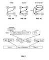
- FIGS. 1A , 1 B and 1 Cillustrate embodiments of different kinds of graphs.
- FIG. 2illustrates an embodiment of the relationship of communication packets, time slots, and superframe cycles.
- FIGS. 3A and 3Billustrate embodiments of the interrelationship of a digraph and a superframe.
- FIG. 4illustrates an embodiment of links between intelligent nodes hopping across channels in different cycles.
- FIGS. 5A , 5 B and 5 Cillustrate embodiments of two digraphs running on the same network of intelligent nodes with their associated superframes.
- FIG. 6illustrates an embodiment of the resulting combined link activity for the intelligent nodes in FIG. 5 .
- FIG. 7Aillustrates an embodiment of the theoretical relationship between crystal frequency error and temperature, before and after temperature compensation.
- FIG. 7Billustrates an embodiment of is the actual measured frequency deviation versus temperature for crystal compensated according to the invention.
- FIG. 8illustrates an embodiment of an on-board clock of the intelligent nodes.
- FIGS. 9A , 9 B, and 9 Cillustrate embodiments of a diagram of a digraph of a simple star-connected network that shows two different implementations of that digraph, one in a superframe with nine slots on a single channel ( FIG. 9B ) and one with twelve slots on three channels ( FIG. 9C ), respectively.
- FIGS. 10A and 10Billustrate embodiments of a digraph associated with a linear network and an implementation of that digraph in a superframe with 12 slots in three channels.
- FIG. 10Cillustrates a digraph network in one embodiment.
- FIG. 10Dillustrates a superframe corresponding to the digraph network of FIG. 10C in one embodiment.
- FIG. 10Eillustrates a superframe corresponding to the digraph network of FIG. 10C in one embodiment.
- FIG. 10Fillustrates a digraph network in one embodiment.
- FIG. 10Gillustrates two superframes corresponding to the digraph network of FIG. 10F in one embodiment.
- FIG. 10Hillustrates a superframe corresponding to the digraph network of FIG. 10F in one embodiment.
- FIG. 10Iillustrates a digraph network in one embodiment.
- FIG. 10Jillustrates two superframes corresponding to the digraph network of FIG. 10I in one embodiment.
- FIG. 10Killustrates a digraph network in one embodiment.
- FIG. 10Lillustrates three superframes corresponding to the digraph network of FIG. 10K in one embodiment.
- FIG. 11illustrates an embodiment of how data storage is organized on the intelligent node, with links and packets associated with superframes.
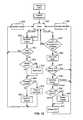
- FIG. 12illustrates an embodiment of an intelligent node state machine associated with communication.
- FIG. 13illustrates an embodiment of signal types into and out of an intelligent node.
- the inventioncan be implemented in numerous ways, including as a process, an apparatus, a system, a composition of matter, a computer readable medium such as a non-transitory computer readable storage medium or a computer network wherein program instructions are sent over optical or electronic communication links.
- these implementations, or any other form that the invention may take,may be referred to as techniques.
- the order of the steps of disclosed processesmay be altered within the scope of the invention.
- Subnetwork communication for a digraph linked networkis disclosed.
- the subnetworkis a set of nodes and links between nodes that are a part of the network.
- Subnetwork communicationhas communication between nodes that are within the subnetwork and uses nodes and links that are within the subnetwork.
- Subnetworkscan offer long superframes which provide slow communication and short superframes which provide fast communication between nodes in the network.
- Digraph networksemploy intelligent nodes comprising a transmitter and receiver, a power source, input devices, sometimes output devices, and an intelligent controller, such as a programmable microprocessor controller with memory.
- networkssuch as the interne, have been developed having configurations or networks for communication that are static, dynamic or a hybrid of static and dynamic. Power for these networks has been most often supplied via wires (the nodes are “plugged in”) or occasionally from batteries. As the size, power, and cost of the computation and communication requirements of these devices has decreased over time, battery powered wireless systems have gotten smaller and smaller and more prevalent. The limit to size scaling resulting from this trend to smaller and lower power wireless devices is in the millimeter size range, leading to predictions of “smart dust”. For this reason, the research community has adopted the name mote to refer to a small wireless sensor device. Mote is an old English word meaning a speck of dust.
- a self-contained unit of communication informationis called a packet.
- a packethas a header, a payload and an optional trailer ( FIG. 2 ).
- a linkis a path which originates at exactly one node and terminates at exactly one other node.
- a nodeis thus any vertex or intersection in a communication network.
- a nodemay be passive or intelligent.
- a nodeis assumed to be an intelligent node in that it is capable of receiving and analyzing information, taking certain actions as a result of received information, including the storing of received or processed information, modifying at least part of received information, and in some instances originating and retransmitting information.
- a cellis a channel-specific time period of fixed duration during which a unit of communication occurs between two fixed terminals without conflict.
- a slotrefers to a time period during which a packet can be sent as well as acknowledged
- a cellrefers to a particular slot and radio channel offset in a superframe (defined below).
- TDMAtime division multiple access
- T-1DS-1
- a frameis a period of time of defined and fixed duration.
- a superframeis an arbitrary number of slots and thus can be of variable duration. A superframe is iterated each cycle, as hereinafter explained.
- Each intelligent node in a networkrepresents its connectivity to other intelligent nodes in the network as a collection of directed links on one or more digraphs.
- Each superframerepeats in a continuous sequence of cycles.
- Each linkcan be used for the transmission and optional acknowledgement of a single packet.
- the available bandwidth from intelligent node A to intelligent node Bis the product of the number of links from A to B in the superframe (links per cycle) and the superframe rate (cycles per second).
- the ability to create multiple superframes of different lengths, and assign different numbers of links between intelligent nodes in each superframeprovides flexibility to the network designer. This flexibility allows bandwidth, redundancy, latency, and many other network performance parameters to be traded off against power consumption.
- Digraphsare the abstract representation of a superframe, and they allow designers to look at and design collections of links and understand their function.
- Each link in a digraphis assigned a cell, that is, a particular time slot offset and channel offset, in the corresponding superframe. In each cycle of the superframe, these two offsets are used together with the cycle number to calculate the exact time and frequency on which the intelligent node is to turn on its radio.
- a graphis defined a collection of vertices or intelligent nodes with connections, or links, between the intelligent nodes.
- a digraphis defined as a graph where all of the links have an associated direction, so that a digraph connects a plurality of intelligent nodes in a network with links defining direction of flow.
- a multi-digraphis defined as a digraph in which there exists at least one pair of links which both originate at the same originating intelligent node and terminate on the same terminating intelligent node.
- Digraph based packet transportis analogous to water flowing in a river delta with its meandering branches. If a number of intelligent entities each in an independent unpropelled watercraft were dropped all over the delta with no means of guidance except to choose a path at each fork, they would take a wide variety of paths, depending on flow and congestion. Eventually, all would arrive at the basin. Two that started far apart might end up close together, and two that started near each other might take completely different paths and arrive at different times.
- a method and apparatus for packet switched transportis provided among intelligent nodes wherein the duty cycling of the intelligent nodes is minimized in order to maximize power life using a synchronization algorithm that assures all nodes are able to propagate information through the network without undue use of transmission and reception power.
- Frequency hopping time-division multiple accesssupports packet communication between intelligent nodes via assigned directed links, each link being assigned to a time-channel offset (cell) in a superframe, so that a link carrying a packet string between any two intelligent nodes is active only during its assigned time slot. The result is efficient use of spectrum and minimal expenditure of power. If multiple superframes are employed and all frequency slots are simultaneously operating in synchronicity, the spectrum has the potential for 100% data utilization, less guard band spectrum.
- the vertices of a graphare the sites of intelligent nodes, also designated “motes,” either physical or symbolic, which are capable of analyzing incoming traffic and sensory data and which can act upon the traffic, reroute traffic and originate information from the site.
- Directed links ( 101 FIG. 1B ) between intelligent nodes A, B, C, and Grepresent communication slots, and multiple links or slots ( FIG. 1C ) provide a mechanism for exhibiting relative available bandwidth between intelligent nodes. Every directed link in a digraph has the capability of transporting one packet in a given communication slot ( FIG. 2 ). Each of these slots has a fixed length and admits the construction of a superframe ( FIG. 2 ) which defines how the links in a given digraph will be distributed in time and frequency.
- a slotis a period of time in a superframe (which consists of N slots) during which a packet may be sent and (optionally) acknowledged. Slots herein have a uniform, fixed duration, and therefore packets carried in any slot have a corresponding maximum data payload size within the constraints of the standard slot.
- Superframesrepeat, and each repetition is called a communication cycle, or simply a cycle. All intelligent nodes in a defined network share the same synchronized view of the occurrences of the edges of slots. Intelligent nodes may participate in multiple graphs/superframes and therefore communicate with other intelligent nodes at very different rates and with different latencies. There may be no single superframe which has slots that contains the traffic of all intelligent nodes in the network.
- All intelligent nodes within a networkhave a shared sense of time, synchronized to within about one millisecond (see below).
- intelligent node Bif intelligent node B is transmitting to intelligent node A in time slot I ( 111 , FIG. 3B ), intelligent node A can therefore expect the transmission to occur within a few milliseconds of the beginning of slot I 111 during each cycle. If the header of the message has not been received within a few milliseconds of the beginning of slot I, ( 114 , FIG. 2 ), intelligent node A will turn off its receiver (go to sleep) assuming that intelligent node B had nothing to send at that particular time.
- the duration of the “acceptable header start time”depends on the accuracy of clock synchronization (in parts per million) among intelligent nodes, as well as the length of delays between exchanges of packets and acknowledgment packets. Taken together, these parameters relate network latency, battery life and the superframe rate, or “chattiness” of the network.
- the intelligent nodesare expected to a shared time base that is off by no more than a few tens of parts per million (PPM). For a 100 second long superframe, that corresponds to a few milliseconds of error after one cycle of a superframe. If longer time periods for superframe length are desired (i.e. less communication chatter) then either the listening time must be increased, with corresponding power increase, or the clock drift must be reduced.
- PPMparts per million
- FIG. 3Aillustrates the implementation a digraph through selection of slots in a time/frequency (slot/channel) plane of a superframe ( FIG. 3B ).
- Time (x-axis)is divided into slots
- frequency (y-axis)is divided into channels, for example in the ISM band from 902.5 MHZ to 927.5 MHz in 500 kHz increments.
- each link in the graphhas a corresponding time/frequency bucket, or slot, in time/frequency space.
- FIG. 3BAn example of channel (frequency) assignment of three links in the multi-digraph is shown in FIG. 3B .
- Typical implementationswould use pseudo-random and potentially time-varying channel/frequency mapping.
- the slot assignmentsare ⁇ 1, 2 ⁇ for B->A #1; ⁇ 3,4 ⁇ for B->A #2, and ⁇ 5,3 ⁇ for C->A, which slots are then repeated each cycle.
- FIG. 4Multiple cycles of a sample superframe, as shown in FIG. 4 , illustrate how the communication channel changes each cycle.
- the communication channel of the slot to which a link is assignedis offset by one channel each superframe.
- each cyclethe actual communication channel is incremented by one (modulo of the number of channels).
- every link in a networkis effectively implemented over a pseudo-random sequence of frequencies. For some networks, this pseudo-random variation in frequency can also be applied to the time slot for the communication.
- both ends of a digraph linkcan be informed as to the future slot usage of a superframe through appropriate identification and authentication, such as ID, password, etc., so that the communication can be effected without reliance on a predetermined slot pattern.
- the endscan identify to each other a selected one of a choice of slot usage patterns over future superframes.
- FIGS. 5A and 5Bare diagrams illustrating two digraphs ( FIG. 5C ) running on the same network of intelligent nodes, with examples of what the superframe associated with each digraph might be.
- the respective digraphsherein labeled solid line and dashed line, corresponding to plain font and dashed line corresponding to bold italicized font, may be implemented on either identical or of independent sets of channels without causing interference with each other.
- FIG. 6illustrates how these two superframes share spectrum.
- the timeslots used by one superframeare blocked with respect to the other superframe.
- the two different digraphs in a networkneed not be implemented with the same transmission rate.
- FIG. 5Bby using a different length frame for the second digraph, in this case a subharmonic of the first digraph, links in the first digraph appear with three times the frequency of the links in the second digraph.
- Superframesare inherently composed of an integral number of slots, but they need not be integer multiples of each other in length. However, as in FIG.
- the second superframe lengthis an integer multiple of the first superframe length, it is possible to guarantee that there will be no collisions between the two superframes.
- using superframe lengths that are prime numberswill ensure that time-slot collisions, when they do occur, are evenly distributed among links.
- a relatively a large number of linksmay be implemented. For an embodiment with 50 channels and a 30 ms slot length, there are over 1500 slot/channel pairs available per second, with room for guard band and guard times.
- each intelligent nodeIn any network type, each intelligent node must store its own collection of links.
- the information that an intelligent node must store to completely characterize a linkis about 20 bytes long (superframe ID, slot, channel, partner, link type, etc.). This allows an intelligent node to store roughly 50 links/KB of RAM.
- the representation and synchronization of time in a sensor networkis essential if the network is synchronous and if energy is to be conserved.
- all intelligent nodesare assumed to have a 32 kHz crystal oscillator, as typically found in a watch, as a time reference.
- Low-cost watch crystalsare advantageous because of their low power consumption (sub-microwatt), but they are known to have substantial variation in frequency in both their manufacturing tolerance, as well as their temperature dependence.
- F oscF nom ⁇ (1+alpha( T ⁇ T nom +T off ) 2 +PPM off +PPM drift )
- F nomis 32,768 Hz
- T nomis 25 degrees C.
- alphais typically 0.0035+/ ⁇ 0.0005 PPM/K 2
- T offis +/ ⁇ 5K
- PPM offis +/ ⁇ 20 PPM
- PPM driftis +/ ⁇ 3 PPM in the first year.
- the majority of the error in clock rateis due to the quadratic dependence of frequency on temperature.
- the room-temperature frequency offset, PPM offas well as the quadratic coefficient, alpha, and the temperature peak offset, T off , can all be measured at the time of manufacture, and a calibration table can be created which represents the difference between the actual frequency of the oscillator and the desired frequency of the oscillator. It is difficult to directly adjust the frequency of the crystal based on this knowledge, but it is relatively straightforward to adjust the digital counter which is incremented each cycle of the crystal.
- FIG. 7Ais a graph of the simulated preliminary results of temperature compensation of the 32 kHz clock.
- the uncompensated crystalsmooth parabolic curve
- the uncompensated crystalhas over 160 PPM error at low temperature.
- Compensating for the slow crystal by adding additional ticks with a frequency dependent on the measured temperatureyields the jagged line.
- FIG. 7Bis the actual preliminary results of temperature compensation of the 32 kHz clock. Measured data remains within roughly 20 PPM of zero error over the range ⁇ 40 deg. C. to +85 deg. C. Because all crystals have slightly different parameters, it is likely that each intelligent node will need to be calibrated at the time of manufacture. This can be done either via a physical connection or an RF communication link. Intelligent nodes are placed in a temperature-controlled environment, informed of the ambient temperature, and given a time reference of some kind, such as a series of synchronizing packets via the RF link from a master controller. Based on this time and temperature reference, the intelligent nodes are expected to determine various calibration compensation parameters and to perform the corresponding compensations.
- the calibrationcan be performed as follows: A simple method is to use table-lookup mapping technique to relate temperature to the appropriate delay for an extra “tick” of the 32 kHz clock. For example, if calibration determines that, at 0 deg. C., the clock is slow by 50 PPM, then every 20,000 ticks (the reciprocal of 50 PPM) a one tick adjustment is added.
- a block diagram of a circuit 150 that illustrate this approach to calibrationis shown in FIG. 8 .
- a 32 kHz oscillator(crystal 151 ) provides the reference, which is corrected for temperature by a temperature sensor 153 , for timing drift by a MAC layer packet timing information compensator 155 , as well as for manufacturing offset, by a compensation circuit 152 that adds occasional ticks.
- Thisdrives a hardware counter 154 that counts ticks directly, optionally augmented by a software counter 156 (e.g., via interrupts generated when the hardware counter rolls over).
- This counter setuprepresents the intelligent node's best guess at how long it has been awake since last reboot.
- Each intelligent nodemaintains a 48-bit counter 158 which represents time since its last reboot, or uptime. Uptime is guaranteed monotonic (non-decreasing), and it is used for on-intelligent node timing of events.
- each intelligent nodemaintains a local standard time offset 160 , which is an estimate of the difference between its internal clock (uptime 158 ) and a global network standard, herein Dust Standard Time (DST) 162 .
- DSTis zero at midnight on Jan. 1, 2003.
- the DST offset 160 valueis subject to modification from a communication information corrector 161 that derives correction information from the MAC layer.
- the DST offset 160 valueis added to uptime value to generate the intelligent node's best guess at the DST 162 value, with correction.
- the DST valueis used to schedule network events, such as communication with other intelligent nodes and for sampling of sensors. If an intelligent node is a part of multiple networks or has multiple parents or gateways, the DST offset for each can be stored separately. Time synchronization across the network is achieved by exchanging timing information in every link.
- Groups of crystalsmanifest a natural distribution above and below their rated frequency, and only those which are slow can be sped up to the nominal frequency, leaving the other crystals to run fast.
- One solution to this problemis to speed all crystals up to a speed that is faster than the nominal crystal frequency.
- FIG. 9Arepresents a simple star-connected network in which three intelligent nodes communicate directly with a fourth gateway intelligent node.
- the digraph in FIG. 9Ashows that there should be two “inward” links from each intelligent node to the gateway, and one “outward” link from the gateway to each mote, giving 9 links total.
- These nine linksmust be assigned to cells in a superframe.
- intelligent node Ahas two opportunities to send a packet to intelligent node G at the beginning of each cycle, and then no more opportunities to send a packet for the rest of the cycle.
- One such assignmentis shown in FIG. 9C .
- FIG. 10A and FIG. 10Bare together an example of a digraph associated with a linear network and an example implementation of that digraph in a superframe with 12 slots. The similarities and differences with the example of FIGS. 9A-C will be evident.
- FIG. 10Cillustrates a digraph network in one embodiment.
- nodesare connected to each other with directional communication links.
- the linksindicate the direction of transmission of packets. In some embodiments, there is communication in the opposite direction of the link in order to acknowledge, or not acknowledge, the proper receipt of a packet after it has been transmitted.
- Gateway node Gis linked to node A 1 , node A 2 , and node A 3 .
- Node A 1is linked to node G and to node B 1 .
- Node A 2is linked to node G, node B 1 , node B 2 , and node B 3 .
- Node A 3is linked to node G and node B 3 .
- Node B 1is linked to node A 1 .
- Node B 2is linked to node A 2 and node B 3 .
- Node B 3is linked to node A 3 and node B 2 .
- FIG. 10Dillustrates a superframe corresponding to the digraph network of FIG. 10C in one embodiment.
- superframe Bcontaining three channels is shown: channel 0 (Ch 0 ), channel 1 (Ch 1 ), and channel 2 (Ch 2 ).
- the superframealso contains nine time slots: slot 0 (S 0 ), slot 1 (S 1 ), slot 2 (S 2 ), slot 3 (S 3 ), slot 4 (S 4 ), slot 5 (S 5 ), slot 6 (S 6 ), slot 7 (S 7 ), and slot 8 (S 8 ).
- slot 0slot 0
- slot 1slot 1
- slot 2S 2
- slot 3S 3
- slot 4S 4
- slot 5S 5
- slot 6slot 6
- slot 7S 7
- slot 8slot 8
- node A 3sends to node B 3 .
- node A 1sends to node G.
- node B 3sends to node B 2 .
- node A 1sends to node B 1 .
- node A 2sends to node G.
- node B 3sends to node A 3 .
- node A 2sends to node B 2 .
- node A 3sends to node G.
- Ch 1 -S 4 cellnode B 2 sends to node B 3 .
- node B 3sends to node B 2 .
- node B 2sends to node B 3 .
- node Gsends to nodes A 1 , A 2 , and A 3 .
- node A 2sends to nodes B 1 , B 2 , and B 3 .
- Ch 1 -S 1 cell, Ch 1 -S 4 cell, Ch 0 -S 5 cell, and Ch 2 -S 6 cellcontain a communication loop that is cycled through multiple times (two times in this case) allowing frequent communication within the subnetwork.
- the superframeis nine time slots overall in length.
- One communication loopis where a packet is transmitted by a first node (node B 3 ) and received by a second node (node B 2 ) and where a packet is also transmitted by the second node (node B 2 ) and received by the first node (node B 3 ).
- FIG. 10Eillustrates a superframe corresponding to the digraph network of FIG. 10C in one embodiment.
- superframe Ccontaining three channels is shown: channel 0 (Ch 0 ), channel 1 (Ch 1 ), and channel 2 (Ch 2 ).
- Ch 0 , Ch 1 , and Ch 2are assigned to frequencies in a pseudo-random sequence of frequencies available to the network.
- the superframealso contains one time slot: slot 0 (S 0 ).
- slot 0S 0
- node B 3sends to node B 2 .
- superframe C and superframe Brun concurrently.
- Superframe Benables communication for all nodes and can maintain time synchronization.
- Superframe Benables data communication, health report communication, and control information communication.
- Superframe Cenables low latency communication from node B 3 to node B 2 .
- superframe B and superframe Crun sequentially; superframe B runs for a predetermined period of time, and then superframe C runs for a predetermined period of time.
- an eventcauses a change from superframe B running to superframe C running or a change from superframe C running to superframe B running, where the event that causes the change can be the reception of information by the network (for example, information that a switch has changed state, a sensor reading an extreme value, or an alarm being triggered), a change to the network state as determined by a gateway node (for example, the gateway calendar indicates that increased monitoring occurs during the week as opposed to on weekends), a status of the network (for example, more power is available), or any other event where a change to the superframe running is useful.
- the networkfor example, information that a switch has changed state, a sensor reading an extreme value, or an alarm being triggered
- a change to the network stateas determined by a gateway node (for example, the gateway calendar indicates that increased monitoring occurs during the week as opposed to on weekends), a status of the network (for example, more power is available), or any other event where a change to the superframe running is useful.
- FIG. 10Fillustrates a digraph network in one embodiment.
- node Ais linked to node B and node E.
- Node Bis linked to node G twice.
- Node Cis linked to node G.
- Node Eis linked to node C.
- Node Fis linked to node E, node C, and node A.
- Node His linked to node B twice and node C.
- there are other supported links in the networkin order to enable time synchronization, health report communication, data communication, and/or control information.
- FIG. 10Gillustrates two superframes corresponding to the digraph network of FIG. 10F in one embodiment.
- superframe D and superframe Einclude the cells with communication between node H and node B and node G.
- Superframe D and superframe Emay contain cells where other nodes communicate with each other, but they are not shown in this example.
- Superframe Dcontains N channels (represented by Ch 0 , Ch 1 , and Ch N) and 30 time slots (represented by S 0 , S 1 , S 15 , and S 29 ).
- Ch 1 -S 15 cellnode H sends to node B.
- Superframe Econtains N channels (represented by Ch 0 , Ch 1 , and Ch N) and 200 time slots (represented by S 0 , S 1 , S 60 , S 142 , S 143 , and S 199 ).
- N channelsrepresented by Ch 0 , Ch 1 , and Ch N
- 200 time slotsrepresented by S 0 , S 1 , S 60 , S 142 , S 143 , and S 199 .
- Ch 0 -S 60 cell and Ch 1 -S 143 cellnode B sends to node G.
- Ch 1 -S 142node H sends to node B.
- FIG. 10Hillustrates a superframe corresponding to the digraph network of FIG. 10F in one embodiment.
- superframe Fincludes the cell with communication between node F and node A.
- Superframe Fcontains N channels (represented by Ch 0 , Ch 1 , and Ch N) and 1 time slot (represented by S 0 ).
- Ch N-S 0 cellnode F sends to node A.
- superframes D, E, and Fall run concurrently.
- Superframe Ehas a long latency (corresponding to the 200 time slots) and can be used for maintaining time synchronization, sending data and health reports, and control information.
- Superframe Dhas a medium latency (corresponding to 30 time slots).
- node Bis a heating ventilation and air conditioning control point and node H is a temperature sensor where the 30 time slots corresponds to approximately a 1 second latency.
- Superframe Fhas a short latency (corresponding to 1 time slot).
- node Fis a light switch and node A is a light and the 1 time slot corresponds to approximately a 30 millisecond latency.
- superframes D, E, and Frun sequentially and the network switches between the superframes based either on triggering events or on predetermined times.
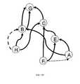
- FIG. 10Iillustrates a digraph network in one embodiment.
- nodesare connected to each other with directional communication links.
- the linksindicate the direction of transmission of packets.
- node Ais linked to node B and node E.
- Node Bis linked to node G twice.
- Node Cis linked to node G.
- Node Eis linked to node C and to node A.
- Node Fis linked to node E twice, node C, and node A.
- Node His linked to node B, node C, node E, and node F.
- there are other supported links in the networkin order to enable time synchronization, health report communication, data communication, and/or control information.
- FIG. 10Jillustrates two superframes corresponding to the digraph network of FIG. 10I in one embodiment.
- superframe Gincludes the cells with communication between nodes A, E, F, and H represented in FIG. 10I with the dotted digraph links.
- Superframe Hincludes the cells with communication between nodes A, B, C, E, F, G, and H represented in FIG. 10I with the solid digraph links.
- Superframe G and Hmay contain cells where other nodes communicate with each other, but they are not shown in this example.
- Superframe Gcontains N channels (represented by Ch 0 , Ch 1 , and Ch N) and 65 time slots (represented by S 0 , S 1 , S 15 , and S 64 ).
- Ch 0 -S 0 cellnode F sends to node E.
- Ch N-S 1 cellnode E sends to node A.
- Ch 0 -S 15 cellnode F sends to node A.
- Ch 1 -S 15 cellnode H sends to node E.
- Ch N-S 64 cellnode H sends to node F.
- Superframe Hcontains N channels (represented by Ch 0 , Ch 1 , and Ch N) and 200 time slots (represented by S 0 , S 1 , S 60 , S 142 , S 143 , and S 199 ).
- node Fsends to node C.
- Ch N-S 0 cellnode A sends to node E.
- Ch 1 -S 1node H sends to node C.
- node Bsends to node G.
- node Esends to node C.
- Ch 1 -S 142 cellnode H sends to node B.
- Ch N-S 142 cellnode C sends to node G.
- node Bsends to node G.
- node Asends to node B.
- node Fsends to node E.
- superframes G and Hrun concurrently.
- Superframe Hhas a long latency (corresponding to the 200 time slots) and can be used for maintaining time synchronization, sending data and health reports, and control information.
- Superframe Ghas a medium latency (corresponding to 65 time slots).
- node His an industrial process sensor and node A is an industrial process controller.
- superframes G and Hrun sequentially and the network switches between the superframes based either on triggering events or on predetermined times.
- FIG. 10Killustrates a digraph network in one embodiment.
- nodesare connected to each other with directional communication links.
- the linksindicate the direction of transmission of packets.
- node Bis linked to node A three times (two solid links and one dashed link).
- Node Cis linked to node A three times (one solid link, one dashed link, and one dotted link).
- Node Eis linked to node C twice (one solid link and one dotted link).
- Node Fis linked to node E (solid link) and node C (solid link).
- Node Gis linked to node B (solid link) and node E twice (one solid link and one dotted link).
- Node his linked to node B twice (one solid link and one dashed link) and node C twice (one solid link and one dashed link).
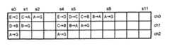
- FIG. 10Lillustrates three superframes corresponding to the digraph network of FIG. 10K in one embodiment.
- superframe Iincludes the cells with communication between nodes G, E, C, and A represented in FIG. 10K with the dotted digraph links.
- Superframe Jincludes the cells with communication between nodes H, B, C, and A represented in FIG. 10K with the dashed digraph links.
- Superframe Kincludes the cells with communication between nodes A, B, C, E, F, G, and H represented in FIG. 10K with the solid digraph links.
- Superframe I, j, and Kmay contain cells where other nodes communicate with each other, but they are not shown in this example.
- Superframe Icontains N channels (represented by Ch 0 , Ch 1 , and Ch N) and 2 time slots (represented by S 0 and S 1 ).
- Ch 0 -S 0 cellnode G sends to node E.
- Ch 1 -S 0 cellnode C sends to node A.
- Ch N-S 1 cellnode E sends to node C.
- Superframe Jcontains N channels (represented by Ch 0 , Ch 1 , and Ch N) and 2 time slots (represented by S 0 and S 1 ).
- node Hsends to node B.
- Ch 1 -S 0 cellnode C sends to node A.
- Ch 0 -S 1 cellnode H sends to node C.
- Ch N-S 1 cellnode B sends to node A.
- Superframe Kcontains N channels (represented by Ch 0 , Ch 1 , and Ch N) and 200 time slots (represented by S 0 , S 1 , S 60 , S 142 , S 143 , and S 199 ).
- Ch 0 -S 0 cellnode B sends to node A.
- node Fsends to node C.
- Ch 0 -S 1node G sends to node E.
- Ch 1 -S 1 cellnode H sends to node B.
- Ch N-S 1 cellnode C sends to node A.
- Ch 0 -S 60 cellnode B sends to node A.
- node Esends to node C.
- node Gsends to node B.
- node Hsends to node C.
- node Fsends to node E.
- superframes Kruns all the time and superframes I and J run only occasionally.
- Superframe Khas a long latency (corresponding to the 200 time slots) and can be used for maintaining time synchronization, sending data and health reports, and control information.
- Superframe Ihas a short latency (corresponding to 2 time slots) with one payload from node G delivered to node A every 2 cycle.
- Superframe Jhas a short latency (corresponding to 2 time slots) with one payload from node H to node A in 1 cycle.
- superframe Ktakes longer to cycle through than superframe I or superframe J.
- node Gis a microphone sending real-time compressed voice information and node H is a camera transferring an image.
- FIG. 11shows an example of how data storage is organized on the intelligent node, with links and packets associated with superframes.
- the efficiency of spectrum and time usageis shown, suggesting how links can be ordered so that they can be optimized.
- FIG. 12shows that part of an intelligent node state machine that is associated with communication. Once a mote is initialized, it invokes an idle or sleep state 300 during which it listens 350 until timeout or until it receives a valid packet 351 , acknowledges 353 . It determines whether to process the packet locally 354 , whereupon the packet is passed to the next layer 355 or is inserted in a queue 356 , and then status is updated.
- a transmit linkOn a transmit link, it decides if it has a packet to send (or a beacon signal) 301 and adds destination and time of transmission stamps 302 to send, either direct or via broadcast 303 . If direct it sets a timeout and listens for acknowledgment 304 , identifies positive or negative acknowledgments 305 and either deletes the packet 306 and/or updates the standard internal time 307 .
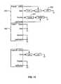
- FIG. 13is a diagram that illustrates signal types on directed links into and out of an intelligent node. It is understood that there are at least three nodes in the digraph. There is are N inputs from a first graph to an intelligent node N and M inputs from graph 2 to intelligent node M, which will respectively result in N plus D outputs on graph 1 and M plus K outputs on graph 2 , indicative of a potential for increase and even crossover of graphs in a superframe. Significantly, the power consumed at intelligent node M is minimized for transmission and receipt by providing for a minimal power idle state when the node is not actively receiving or transmitting in accordance with the synchronization of timing among nodes in the digraph.
Landscapes
- Engineering & Computer Science (AREA)
- Computer Networks & Wireless Communication (AREA)
- Signal Processing (AREA)
- Mobile Radio Communication Systems (AREA)
Abstract
Description
Fosc=Fnom·(1+alpha(T−Tnom+Toff)2+PPMoff+PPMdrift)
where Fnom, is 32,768 Hz, Tnomis 25 degrees C., and alpha is typically 0.0035+/−0.0005 PPM/K2, Toffis +/−5K, PPMoffis +/−20 PPM, and PPMdriftis +/−3 PPM in the first year.
Claims (27)
Priority Applications (1)
| Application Number | Priority Date | Filing Date | Title |
|---|---|---|---|
| US11/152,026US7961664B1 (en) | 2004-03-27 | 2005-06-13 | Digraph network subnetworks |
Applications Claiming Priority (3)
| Application Number | Priority Date | Filing Date | Title |
|---|---|---|---|
| US55714804P | 2004-03-27 | 2004-03-27 | |
| US10/960,709US7529217B2 (en) | 2004-03-27 | 2004-10-06 | Low-power autonomous node for mesh communication network |
| US11/152,026US7961664B1 (en) | 2004-03-27 | 2005-06-13 | Digraph network subnetworks |
Related Parent Applications (1)
| Application Number | Title | Priority Date | Filing Date |
|---|---|---|---|
| US10/960,709Continuation-In-PartUS7529217B2 (en) | 2004-03-27 | 2004-10-06 | Low-power autonomous node for mesh communication network |
Publications (1)
| Publication Number | Publication Date |
|---|---|
| US7961664B1true US7961664B1 (en) | 2011-06-14 |
Family
ID=44121934
Family Applications (1)
| Application Number | Title | Priority Date | Filing Date |
|---|---|---|---|
| US11/152,026Active2026-11-24US7961664B1 (en) | 2004-03-27 | 2005-06-13 | Digraph network subnetworks |
Country Status (1)
| Country | Link |
|---|---|
| US (1) | US7961664B1 (en) |
Cited By (2)
| Publication number | Priority date | Publication date | Assignee | Title |
|---|---|---|---|---|
| US20060029060A1 (en)* | 2004-08-05 | 2006-02-09 | Dust Networks | Digraph based mesh communication network |
| US20080279204A1 (en)* | 2007-04-13 | 2008-11-13 | Hart Communication Foundation | Increasing Reliability and Reducing Latency in a Wireless Network |
Citations (67)
| Publication number | Priority date | Publication date | Assignee | Title |
|---|---|---|---|---|
| US3737746A (en) | 1972-04-19 | 1973-06-05 | Gen Time Corp | Quartz crystal controlled stepper motor |
| US4550397A (en) | 1983-12-16 | 1985-10-29 | At&T Bell Laboratories | Alternate paths in a self-routing packet switching network |
| US4939726A (en) | 1989-07-18 | 1990-07-03 | Metricom, Inc. | Method for routing packets in a packet communication network |
| US4947388A (en) | 1988-04-06 | 1990-08-07 | Hitachi, Ltd. | Cell switching system of asynchronous transfer mode |
| US5007052A (en) | 1989-04-11 | 1991-04-09 | Metricom, Inc. | Method for routing packets by squelched flooding |
| US5007752A (en) | 1988-08-05 | 1991-04-16 | Alps Electric Co., Ltd. | Paper feed roller arrangement for printer |
| US5079768A (en) | 1990-03-23 | 1992-01-07 | Metricom, Inc. | Method for frequency sharing in frequency hopping communications network |
| US5115433A (en) | 1989-07-18 | 1992-05-19 | Metricom, Inc. | Method and system for routing packets in a packet communication network |
| US5128938A (en) | 1989-03-03 | 1992-07-07 | Motorola, Inc. | Energy saving protocol for a communication system |
| US5128932A (en) | 1990-08-27 | 1992-07-07 | Bell Communications Research, Inc. | Traffic flow control and call set-up in multi-hop broadband networks |
| US5130987A (en) | 1990-03-23 | 1992-07-14 | Metricom, Inc. | Method for synchronizing a wide area network without global synchronizing |
| US5241673A (en) | 1990-06-05 | 1993-08-31 | Oce-Nederland B.V. | System for garbage collecting unused memory space represented by a digraph by assigning values of node identifiers to selected variables based upon predetermined conditions |
| GB2271691A (en) | 1992-09-21 | 1994-04-20 | Oconnor P J | Synchronisation of a radio telemetry system |
| US5471469A (en) | 1994-02-08 | 1995-11-28 | Metricon, Inc. | Method of resolving media contention in radio communication links |
| US5488608A (en) | 1994-04-14 | 1996-01-30 | Metricom, Inc. | Method and system for routing packets in a packet communication network using locally constructed routing tables |
| US5515369A (en) | 1994-06-24 | 1996-05-07 | Metricom, Inc. | Method for frequency sharing and frequency punchout in frequency hopping communications network |
| US5570084A (en) | 1994-06-28 | 1996-10-29 | Metricom, Inc. | Method of loose source routing over disparate network types in a packet communication network |
| US5748103A (en) | 1995-11-13 | 1998-05-05 | Vitalcom, Inc. | Two-way TDMA telemetry system with power conservation features |
| US5903566A (en) | 1994-06-24 | 1999-05-11 | Metricom, Inc. | Method for distributing program code to intelligent nodes in a wireless mesh data communication network |
| US6049708A (en) | 1997-01-24 | 2000-04-11 | Nec Corporation | Mobile communication apparatus for intermittently receiving a broadcasting signal at a corrected reception timing |
| US6081511A (en) | 1996-08-14 | 2000-06-27 | Cabletron Systems, Inc. | Load sharing for redundant networks |
| US6208668B1 (en) | 1997-11-26 | 2001-03-27 | Motorola, Inc. | Apparatus and method for acquiring an operating channel |
| US20010053176A1 (en) | 2000-03-31 | 2001-12-20 | Fry Terry L. | Method and apparatus for characterizing and adjusting a crystal oscillator for use in a spread spectrum, frequency hopping transceiver |
| US6347340B1 (en) | 2000-02-18 | 2002-02-12 | Mobilesys, Inc. | Apparatus and method for converting a network message to a wireless transport message using a modular architecture |
| US20020126627A1 (en) | 2001-03-09 | 2002-09-12 | Qicai Shi | Multiple access protocol and structure for communication devices in an asynchronous network |
| US20030087617A1 (en) | 1999-08-10 | 2003-05-08 | Aki Shohara | Radio frequency control for communication systems |
| US20030134644A1 (en) | 2002-01-17 | 2003-07-17 | Motorola, Inc. | Method and apparatus for adapting a routing map for a wireless communications network |
| US6621805B1 (en) | 1999-10-25 | 2003-09-16 | Hrl Laboratories, Llc | Method and apparatus for multicasting real-time variable bit-rate traffic in wireless Ad-Hoc networks |
| US6639957B2 (en) | 2002-02-14 | 2003-10-28 | Itron, Inc. | Method and system for calibrating an oscillator circuit using a network based time reference |
| US6667957B1 (en) | 1998-03-14 | 2003-12-23 | University Of Maryland | Adaptive routing method for a dynamic network |
| US6671525B2 (en) | 2001-12-13 | 2003-12-30 | Motorola, Inc. | Beacon assisted hybrid asynchronous wireless communications protocol |
| US6678252B1 (en) | 1999-10-28 | 2004-01-13 | Verizon Laboratories Inc. | Method and apparatus for dynamic source routing in ad hoc wireless networks |
| US6690657B1 (en)* | 2000-02-25 | 2004-02-10 | Berkeley Concept Research Corporation | Multichannel distributed wireless repeater network |
| US6690655B1 (en) | 2000-10-19 | 2004-02-10 | Motorola, Inc. | Low-powered communication system and method of operation |
| US20040042405A1 (en) | 2002-08-29 | 2004-03-04 | Nesbitt David W. | Automated route determination |
| US6714552B1 (en) | 1996-08-28 | 2004-03-30 | British Telecommunications Public Limited Company | Communications network |
| US6735178B1 (en) | 2000-05-10 | 2004-05-11 | Ricochet Networks, Inc. | Method for maximizing throughput for multiple links using directional elements |
| US6788702B1 (en) | 1999-10-15 | 2004-09-07 | Nokia Wireless Routers, Inc. | Protocol for neighborhood-established transmission scheduling |
| US6804503B2 (en) | 1998-06-01 | 2004-10-12 | Broadcom Corporation | Communication device with a self-calibrating sleep timer |
| US6826607B1 (en) | 1999-10-06 | 2004-11-30 | Sensoria Corporation | Apparatus for internetworked hybrid wireless integrated network sensors (WINS) |
| US20040266481A1 (en) | 2002-03-18 | 2004-12-30 | Jay Patel | RF ID tag reader utilizing a scanning antenna system and method |
| US20050041627A1 (en) | 2003-08-22 | 2005-02-24 | Samsung Electronics Co., Ltd. | Apparatus and method for collecting active route topology information in a mobile AD HOC network |
| US20050124346A1 (en) | 2003-12-05 | 2005-06-09 | Microsoft Corporation | Hooker mode technique for growing mesh networking footprint and recapturing lost nodes |
| US20050159106A1 (en)* | 2003-12-30 | 2005-07-21 | Arto Palin | Method and system for assigning time-frequency codes |
| US20050155839A1 (en) | 2004-01-20 | 2005-07-21 | J.J. Mackay Canada Limited | Efficient battery powered electronic parking meter |
| US20050195105A1 (en) | 2003-09-04 | 2005-09-08 | Mcburney Paul W. | Keeping accurate time for a hybrid GPS receiver and mobile phone when powered off |
| US20050249170A1 (en)* | 2004-05-05 | 2005-11-10 | Juha Salokannel | Adaptive beacon period in a distributed network |
| US20060007947A1 (en) | 2004-07-07 | 2006-01-12 | Jin Li | Efficient one-to-many content distribution in a peer-to-peer computer network |
| US7002910B2 (en) | 2000-10-30 | 2006-02-21 | The Regents Of The University Of California | Receiver-initiated channel-hopping (RICH) method for wireless communication networks |
| US20060062188A1 (en)* | 2004-09-20 | 2006-03-23 | Kaisa Nyberg | Replay prevention in wireless communications networks |
| US7035240B1 (en) | 2000-12-27 | 2006-04-25 | Massachusetts Institute Of Technology | Method for low-energy adaptive clustering hierarchy |
| US7046166B2 (en) | 2003-04-29 | 2006-05-16 | Rockwell Scientific Licensing, Llc | Modular wireless integrated network sensor (WINS) node with a dual bus architecture |
| US20060187866A1 (en) | 2004-12-20 | 2006-08-24 | Sensicast Systems | Method for reporting and accumulating data in a wireless communication network |
| US7119676B1 (en) | 2003-10-09 | 2006-10-10 | Innovative Wireless Technologies, Inc. | Method and apparatus for multi-waveform wireless sensor network |
| US7127254B2 (en) | 2002-03-11 | 2006-10-24 | Freescale Semiconductor, Inc. | Method of using sub-rate slots in an ultrawide bandwidth system |
| US20060239333A1 (en) | 2005-04-22 | 2006-10-26 | David Albert | Wireless communication system and related methods |
| US7133373B2 (en)* | 2003-12-19 | 2006-11-07 | Motorola, Inc. | Wireless network with improved sharing of high power consumption tasks |
| US7142524B2 (en) | 2002-05-01 | 2006-11-28 | Meshnetworks, Inc. | System and method for using an ad-hoc routing algorithm based on activity detection in an ad-hoc network |
| US7221686B1 (en) | 2001-11-30 | 2007-05-22 | Meshnetworks, Inc. | System and method for computing the signal propagation time and the clock correction for mobile stations in a wireless network |
| US7245405B2 (en) | 2001-04-11 | 2007-07-17 | Hughes Network Systems, Llc | Method and system for performing stateless compression of messages |
| US7280518B2 (en)* | 2001-10-03 | 2007-10-09 | Freescale Semiconductor, Inc. | Method of operating a media access controller |
| US20070258508A1 (en) | 2003-07-17 | 2007-11-08 | Werb Jay P | Method and apparatus for wireless communication in a mesh network |
| US7305240B2 (en) | 2005-02-03 | 2007-12-04 | Intel Corporation | Method and system of network management software architectures for mobile broadband wireless networks |
| US7324559B2 (en) | 2001-05-16 | 2008-01-29 | Mcgibney Grant H | Centralized synchronization for wireless networks |
| US20080031213A1 (en) | 2002-01-02 | 2008-02-07 | Kaiser William J | Autonomous tracking wireless imaging sensor network |
| US7385943B2 (en)* | 2001-05-22 | 2008-06-10 | Alcatel | Method of allocating communication resources in an MF-TDMA telecommunication system |
| US7715336B2 (en)* | 2003-02-14 | 2010-05-11 | Onlive, Inc. | Method of operation for a three-dimensional, wireless network |
- 2005
- 2005-06-13USUS11/152,026patent/US7961664B1/enactiveActive
Patent Citations (67)
| Publication number | Priority date | Publication date | Assignee | Title |
|---|---|---|---|---|
| US3737746A (en) | 1972-04-19 | 1973-06-05 | Gen Time Corp | Quartz crystal controlled stepper motor |
| US4550397A (en) | 1983-12-16 | 1985-10-29 | At&T Bell Laboratories | Alternate paths in a self-routing packet switching network |
| US4947388A (en) | 1988-04-06 | 1990-08-07 | Hitachi, Ltd. | Cell switching system of asynchronous transfer mode |
| US5007752A (en) | 1988-08-05 | 1991-04-16 | Alps Electric Co., Ltd. | Paper feed roller arrangement for printer |
| US5128938A (en) | 1989-03-03 | 1992-07-07 | Motorola, Inc. | Energy saving protocol for a communication system |
| US5007052A (en) | 1989-04-11 | 1991-04-09 | Metricom, Inc. | Method for routing packets by squelched flooding |
| US4939726A (en) | 1989-07-18 | 1990-07-03 | Metricom, Inc. | Method for routing packets in a packet communication network |
| US5115433A (en) | 1989-07-18 | 1992-05-19 | Metricom, Inc. | Method and system for routing packets in a packet communication network |
| US5079768A (en) | 1990-03-23 | 1992-01-07 | Metricom, Inc. | Method for frequency sharing in frequency hopping communications network |
| US5130987A (en) | 1990-03-23 | 1992-07-14 | Metricom, Inc. | Method for synchronizing a wide area network without global synchronizing |
| US5241673A (en) | 1990-06-05 | 1993-08-31 | Oce-Nederland B.V. | System for garbage collecting unused memory space represented by a digraph by assigning values of node identifiers to selected variables based upon predetermined conditions |
| US5128932A (en) | 1990-08-27 | 1992-07-07 | Bell Communications Research, Inc. | Traffic flow control and call set-up in multi-hop broadband networks |
| GB2271691A (en) | 1992-09-21 | 1994-04-20 | Oconnor P J | Synchronisation of a radio telemetry system |
| US5471469A (en) | 1994-02-08 | 1995-11-28 | Metricon, Inc. | Method of resolving media contention in radio communication links |
| US5488608A (en) | 1994-04-14 | 1996-01-30 | Metricom, Inc. | Method and system for routing packets in a packet communication network using locally constructed routing tables |
| US5515369A (en) | 1994-06-24 | 1996-05-07 | Metricom, Inc. | Method for frequency sharing and frequency punchout in frequency hopping communications network |
| US5903566A (en) | 1994-06-24 | 1999-05-11 | Metricom, Inc. | Method for distributing program code to intelligent nodes in a wireless mesh data communication network |
| US5570084A (en) | 1994-06-28 | 1996-10-29 | Metricom, Inc. | Method of loose source routing over disparate network types in a packet communication network |
| US5748103A (en) | 1995-11-13 | 1998-05-05 | Vitalcom, Inc. | Two-way TDMA telemetry system with power conservation features |
| US6081511A (en) | 1996-08-14 | 2000-06-27 | Cabletron Systems, Inc. | Load sharing for redundant networks |
| US6714552B1 (en) | 1996-08-28 | 2004-03-30 | British Telecommunications Public Limited Company | Communications network |
| US6049708A (en) | 1997-01-24 | 2000-04-11 | Nec Corporation | Mobile communication apparatus for intermittently receiving a broadcasting signal at a corrected reception timing |
| US6208668B1 (en) | 1997-11-26 | 2001-03-27 | Motorola, Inc. | Apparatus and method for acquiring an operating channel |
| US6667957B1 (en) | 1998-03-14 | 2003-12-23 | University Of Maryland | Adaptive routing method for a dynamic network |
| US6804503B2 (en) | 1998-06-01 | 2004-10-12 | Broadcom Corporation | Communication device with a self-calibrating sleep timer |
| US20030087617A1 (en) | 1999-08-10 | 2003-05-08 | Aki Shohara | Radio frequency control for communication systems |
| US6826607B1 (en) | 1999-10-06 | 2004-11-30 | Sensoria Corporation | Apparatus for internetworked hybrid wireless integrated network sensors (WINS) |
| US6788702B1 (en) | 1999-10-15 | 2004-09-07 | Nokia Wireless Routers, Inc. | Protocol for neighborhood-established transmission scheduling |
| US6621805B1 (en) | 1999-10-25 | 2003-09-16 | Hrl Laboratories, Llc | Method and apparatus for multicasting real-time variable bit-rate traffic in wireless Ad-Hoc networks |
| US6678252B1 (en) | 1999-10-28 | 2004-01-13 | Verizon Laboratories Inc. | Method and apparatus for dynamic source routing in ad hoc wireless networks |
| US6347340B1 (en) | 2000-02-18 | 2002-02-12 | Mobilesys, Inc. | Apparatus and method for converting a network message to a wireless transport message using a modular architecture |
| US6690657B1 (en)* | 2000-02-25 | 2004-02-10 | Berkeley Concept Research Corporation | Multichannel distributed wireless repeater network |
| US20010053176A1 (en) | 2000-03-31 | 2001-12-20 | Fry Terry L. | Method and apparatus for characterizing and adjusting a crystal oscillator for use in a spread spectrum, frequency hopping transceiver |
| US6735178B1 (en) | 2000-05-10 | 2004-05-11 | Ricochet Networks, Inc. | Method for maximizing throughput for multiple links using directional elements |
| US6690655B1 (en) | 2000-10-19 | 2004-02-10 | Motorola, Inc. | Low-powered communication system and method of operation |
| US7002910B2 (en) | 2000-10-30 | 2006-02-21 | The Regents Of The University Of California | Receiver-initiated channel-hopping (RICH) method for wireless communication networks |
| US7035240B1 (en) | 2000-12-27 | 2006-04-25 | Massachusetts Institute Of Technology | Method for low-energy adaptive clustering hierarchy |
| US20020126627A1 (en) | 2001-03-09 | 2002-09-12 | Qicai Shi | Multiple access protocol and structure for communication devices in an asynchronous network |
| US7245405B2 (en) | 2001-04-11 | 2007-07-17 | Hughes Network Systems, Llc | Method and system for performing stateless compression of messages |
| US7324559B2 (en) | 2001-05-16 | 2008-01-29 | Mcgibney Grant H | Centralized synchronization for wireless networks |
| US7385943B2 (en)* | 2001-05-22 | 2008-06-10 | Alcatel | Method of allocating communication resources in an MF-TDMA telecommunication system |
| US7280518B2 (en)* | 2001-10-03 | 2007-10-09 | Freescale Semiconductor, Inc. | Method of operating a media access controller |
| US7221686B1 (en) | 2001-11-30 | 2007-05-22 | Meshnetworks, Inc. | System and method for computing the signal propagation time and the clock correction for mobile stations in a wireless network |
| US6671525B2 (en) | 2001-12-13 | 2003-12-30 | Motorola, Inc. | Beacon assisted hybrid asynchronous wireless communications protocol |
| US20080031213A1 (en) | 2002-01-02 | 2008-02-07 | Kaiser William J | Autonomous tracking wireless imaging sensor network |
| US20030134644A1 (en) | 2002-01-17 | 2003-07-17 | Motorola, Inc. | Method and apparatus for adapting a routing map for a wireless communications network |
| US6639957B2 (en) | 2002-02-14 | 2003-10-28 | Itron, Inc. | Method and system for calibrating an oscillator circuit using a network based time reference |
| US7127254B2 (en) | 2002-03-11 | 2006-10-24 | Freescale Semiconductor, Inc. | Method of using sub-rate slots in an ultrawide bandwidth system |
| US20040266481A1 (en) | 2002-03-18 | 2004-12-30 | Jay Patel | RF ID tag reader utilizing a scanning antenna system and method |
| US7142524B2 (en) | 2002-05-01 | 2006-11-28 | Meshnetworks, Inc. | System and method for using an ad-hoc routing algorithm based on activity detection in an ad-hoc network |
| US20040042405A1 (en) | 2002-08-29 | 2004-03-04 | Nesbitt David W. | Automated route determination |
| US7715336B2 (en)* | 2003-02-14 | 2010-05-11 | Onlive, Inc. | Method of operation for a three-dimensional, wireless network |
| US7046166B2 (en) | 2003-04-29 | 2006-05-16 | Rockwell Scientific Licensing, Llc | Modular wireless integrated network sensor (WINS) node with a dual bus architecture |
| US20070258508A1 (en) | 2003-07-17 | 2007-11-08 | Werb Jay P | Method and apparatus for wireless communication in a mesh network |
| US20050041627A1 (en) | 2003-08-22 | 2005-02-24 | Samsung Electronics Co., Ltd. | Apparatus and method for collecting active route topology information in a mobile AD HOC network |
| US20050195105A1 (en) | 2003-09-04 | 2005-09-08 | Mcburney Paul W. | Keeping accurate time for a hybrid GPS receiver and mobile phone when powered off |
| US7119676B1 (en) | 2003-10-09 | 2006-10-10 | Innovative Wireless Technologies, Inc. | Method and apparatus for multi-waveform wireless sensor network |
| US20050124346A1 (en) | 2003-12-05 | 2005-06-09 | Microsoft Corporation | Hooker mode technique for growing mesh networking footprint and recapturing lost nodes |
| US7133373B2 (en)* | 2003-12-19 | 2006-11-07 | Motorola, Inc. | Wireless network with improved sharing of high power consumption tasks |
| US20050159106A1 (en)* | 2003-12-30 | 2005-07-21 | Arto Palin | Method and system for assigning time-frequency codes |
| US20050155839A1 (en) | 2004-01-20 | 2005-07-21 | J.J. Mackay Canada Limited | Efficient battery powered electronic parking meter |
| US20050249170A1 (en)* | 2004-05-05 | 2005-11-10 | Juha Salokannel | Adaptive beacon period in a distributed network |
| US20060007947A1 (en) | 2004-07-07 | 2006-01-12 | Jin Li | Efficient one-to-many content distribution in a peer-to-peer computer network |
| US20060062188A1 (en)* | 2004-09-20 | 2006-03-23 | Kaisa Nyberg | Replay prevention in wireless communications networks |
| US20060187866A1 (en) | 2004-12-20 | 2006-08-24 | Sensicast Systems | Method for reporting and accumulating data in a wireless communication network |
| US7305240B2 (en) | 2005-02-03 | 2007-12-04 | Intel Corporation | Method and system of network management software architectures for mobile broadband wireless networks |
| US20060239333A1 (en) | 2005-04-22 | 2006-10-26 | David Albert | Wireless communication system and related methods |
Non-Patent Citations (4)
| Title |
|---|
| Hohlt et al., Flexible Power Scheduling for Sensor Networks, Apr. 26-27, 2004. |
| IEEE, IEEE Standard for Information Technology, 802.15.4(TM), Part 15.4: Wireless Medium Access Control (MAC) and Physical Layer (PHY) Specifications for Low-Rate Wireless Personal Area Networks (LR-WPANS), Oct. 1, 2003, Book. |
| IEEE, IEEE Standard for Information Technology, 802.15.4™, Part 15.4: Wireless Medium Access Control (MAC) and Physical Layer (PHY) Specifications for Low-Rate Wireless Personal Area Networks (LR-WPANS), Oct. 1, 2003, Book. |
| Polastre et al., Versatile Low Power Media Access for Wireless Sensor Networks, Nov. 3-5, 2004. |
Cited By (4)
| Publication number | Priority date | Publication date | Assignee | Title |
|---|---|---|---|---|
| US20060029060A1 (en)* | 2004-08-05 | 2006-02-09 | Dust Networks | Digraph based mesh communication network |
| US8194655B2 (en)* | 2004-08-05 | 2012-06-05 | Dust Networks, Inc. | Digraph based mesh communication network |
| US20080279204A1 (en)* | 2007-04-13 | 2008-11-13 | Hart Communication Foundation | Increasing Reliability and Reducing Latency in a Wireless Network |
| US8798084B2 (en)* | 2007-04-13 | 2014-08-05 | Hart Communication Foundation | Increasing reliability and reducing latency in a wireless network |
Similar Documents
| Publication | Publication Date | Title |
|---|---|---|
| US7881239B2 (en) | Low-powered autonomous radio node with temperature sensor and crystal oscillator | |
| US7529217B2 (en) | Low-power autonomous node for mesh communication network | |
| US7873043B2 (en) | Digraph network superframes | |
| CN114050884B (en) | Cross-network time synchronization method for industrial wireless and TSN fusion | |
| Ramanathan et al. | A stream-oriented power management protocol for low duty cycle sensor network applications | |
| EP2074717B1 (en) | Wireless mesh network with multisized timeslots for tdma communication | |
| US8351369B2 (en) | Apparatus and method for adaptive data packet scheduling in mesh networks | |
| US8619789B2 (en) | Timing re-synchronization with reduced communication energy in frequency hopping communication networks | |
| US7113536B2 (en) | Rendezvous point interpiconet scheduling | |
| Murillo et al. | Bluetooth now or low energy: Should BLE mesh become a flooding or connection oriented network? | |
| US20160080030A1 (en) | Fast frequency-hopping schedule recovery | |
| US9510362B2 (en) | Overlaying receive schedules for energy-constrained devices in channel-hopping networks | |
| CN102118849A (en) | Time synchronization method applicable to wireless sensor network | |
| CN112910501B (en) | Drowsy device operation in asynchronous channel hopping networks | |
| US8385256B2 (en) | Method and system for efficient synchronization in a wireless communication system | |
| EP2232777A2 (en) | Apparatus and method for adaptive channel hopping in mesh networks | |
| Suriyachai et al. | Implementation of a MAC protocol for QoS support in wireless sensor networks | |
| US8059629B1 (en) | Digraph network timing synchronization | |
| US7961664B1 (en) | Digraph network subnetworks | |
| Čečil et al. | Retis–real-time sensitive wireless communication solution for industrial control applications | |
| Yagiri et al. | Recovery of synchronization for wireless sensor networks | |
| Raja | The minimum cost forwarding using MAC protocol for wireless sensor networks | |
| Toma et al. | Research Article Wireless HDLC Protocol for Energy-Efficient Large-Scale Linear Wireless Sensor Networks | |
| Fontanelli et al. | Towards master-less wsn clock synchronization with a light communication protocol | |
| Cosar et al. | A-Stack: a TDMA framework for reliable, real-time and high data-rate wireless sensor networks |
Legal Events
| Date | Code | Title | Description |
|---|---|---|---|
| AS | Assignment | Owner name:DUST NETWORKS, INC., CALIFORNIA Free format text:ASSIGNMENT OF ASSIGNORS INTEREST;ASSIGNORS:PISTER, KRISTOFER S. J.;SHEAR, ROBERT M.;REEL/FRAME:016576/0251 Effective date:20050629 | |
| STCF | Information on status: patent grant | Free format text:PATENTED CASE | |
| FPAY | Fee payment | Year of fee payment:4 | |
| AS | Assignment | Owner name:LINEAR TECHNOLOGY CORPORATION, CALIFORNIA Free format text:MERGER;ASSIGNOR:DUST NETWORKS, INC.;REEL/FRAME:037537/0568 Effective date:20150521 | |
| MAFP | Maintenance fee payment | Free format text:PAYMENT OF MAINTENANCE FEE, 8TH YEAR, LARGE ENTITY (ORIGINAL EVENT CODE: M1552); ENTITY STATUS OF PATENT OWNER: LARGE ENTITY Year of fee payment:8 | |
| AS | Assignment | Owner name:LINEAR TECHNOLOGY LLC, CALIFORNIA Free format text:CHANGE OF NAME;ASSIGNOR:LINEAR TECHNOLOGY CORPORATION;REEL/FRAME:057426/0439 Effective date:20170502 Owner name:ANALOG DEVICES INTERNATIONAL UNLIMITED COMPANY, IRELAND Free format text:CHANGE OF NAME;ASSIGNOR:LINEAR TECHNOLOGY LLC;REEL/FRAME:057422/0532 Effective date:20181105 | |
| MAFP | Maintenance fee payment | Free format text:PAYMENT OF MAINTENANCE FEE, 12TH YEAR, LARGE ENTITY (ORIGINAL EVENT CODE: M1553); ENTITY STATUS OF PATENT OWNER: LARGE ENTITY Year of fee payment:12 |