US7961113B2 - Networkable LED-based lighting fixtures and methods for powering and controlling same - Google Patents
Networkable LED-based lighting fixtures and methods for powering and controlling sameDownload PDFInfo
- Publication number
- US7961113B2 US7961113B2US11/875,196US87519607AUS7961113B2US 7961113 B2US7961113 B2US 7961113B2US 87519607 AUS87519607 AUS 87519607AUS 7961113 B2US7961113 B2US 7961113B2
- Authority
- US
- United States
- Prior art keywords
- lighting
- led
- fixture
- lighting unit
- modular
- Prior art date
- Legal status (The legal status is an assumption and is not a legal conclusion. Google has not performed a legal analysis and makes no representation as to the accuracy of the status listed.)
- Active, expires
Links
Images


Classifications
- H—ELECTRICITY
- H05—ELECTRIC TECHNIQUES NOT OTHERWISE PROVIDED FOR
- H05B—ELECTRIC HEATING; ELECTRIC LIGHT SOURCES NOT OTHERWISE PROVIDED FOR; CIRCUIT ARRANGEMENTS FOR ELECTRIC LIGHT SOURCES, IN GENERAL
- H05B45/00—Circuit arrangements for operating light-emitting diodes [LED]
- H—ELECTRICITY
- H05—ELECTRIC TECHNIQUES NOT OTHERWISE PROVIDED FOR
- H05B—ELECTRIC HEATING; ELECTRIC LIGHT SOURCES NOT OTHERWISE PROVIDED FOR; CIRCUIT ARRANGEMENTS FOR ELECTRIC LIGHT SOURCES, IN GENERAL
- H05B45/00—Circuit arrangements for operating light-emitting diodes [LED]
- H05B45/20—Controlling the colour of the light
- H—ELECTRICITY
- H05—ELECTRIC TECHNIQUES NOT OTHERWISE PROVIDED FOR
- H05B—ELECTRIC HEATING; ELECTRIC LIGHT SOURCES NOT OTHERWISE PROVIDED FOR; CIRCUIT ARRANGEMENTS FOR ELECTRIC LIGHT SOURCES, IN GENERAL
- H05B45/00—Circuit arrangements for operating light-emitting diodes [LED]
- H05B45/30—Driver circuits
- H05B45/37—Converter circuits
- H05B45/3725—Switched mode power supply [SMPS]
- H—ELECTRICITY
- H05—ELECTRIC TECHNIQUES NOT OTHERWISE PROVIDED FOR
- H05B—ELECTRIC HEATING; ELECTRIC LIGHT SOURCES NOT OTHERWISE PROVIDED FOR; CIRCUIT ARRANGEMENTS FOR ELECTRIC LIGHT SOURCES, IN GENERAL
- H05B47/00—Circuit arrangements for operating light sources in general, i.e. where the type of light source is not relevant
- H05B47/10—Controlling the light source
- H05B47/155—Coordinated control of two or more light sources
- H—ELECTRICITY
- H05—ELECTRIC TECHNIQUES NOT OTHERWISE PROVIDED FOR
- H05B—ELECTRIC HEATING; ELECTRIC LIGHT SOURCES NOT OTHERWISE PROVIDED FOR; CIRCUIT ARRANGEMENTS FOR ELECTRIC LIGHT SOURCES, IN GENERAL
- H05B47/00—Circuit arrangements for operating light sources in general, i.e. where the type of light source is not relevant
- H05B47/10—Controlling the light source
- H05B47/175—Controlling the light source by remote control
- H05B47/18—Controlling the light source by remote control via data-bus transmission
- H05B47/184—Controlling the light source by remote control via data-bus transmission using digital multiplexed [DMX] communication protocols
- H—ELECTRICITY
- H05—ELECTRIC TECHNIQUES NOT OTHERWISE PROVIDED FOR
- H05B—ELECTRIC HEATING; ELECTRIC LIGHT SOURCES NOT OTHERWISE PROVIDED FOR; CIRCUIT ARRANGEMENTS FOR ELECTRIC LIGHT SOURCES, IN GENERAL
- H05B47/00—Circuit arrangements for operating light sources in general, i.e. where the type of light source is not relevant
- H05B47/10—Controlling the light source
- H05B47/175—Controlling the light source by remote control
- H05B47/196—Controlling the light source by remote control characterised by user interface arrangements
- H—ELECTRICITY
- H05—ELECTRIC TECHNIQUES NOT OTHERWISE PROVIDED FOR
- H05B—ELECTRIC HEATING; ELECTRIC LIGHT SOURCES NOT OTHERWISE PROVIDED FOR; CIRCUIT ARRANGEMENTS FOR ELECTRIC LIGHT SOURCES, IN GENERAL
- H05B45/00—Circuit arrangements for operating light-emitting diodes [LED]
- H05B45/30—Driver circuits
- H05B45/32—Pulse-control circuits
- H05B45/325—Pulse-width modulation [PWM]
- H—ELECTRICITY
- H05—ELECTRIC TECHNIQUES NOT OTHERWISE PROVIDED FOR
- H05B—ELECTRIC HEATING; ELECTRIC LIGHT SOURCES NOT OTHERWISE PROVIDED FOR; CIRCUIT ARRANGEMENTS FOR ELECTRIC LIGHT SOURCES, IN GENERAL
- H05B45/00—Circuit arrangements for operating light-emitting diodes [LED]
- H05B45/30—Driver circuits
- H05B45/32—Pulse-control circuits
- H05B45/33—Pulse-amplitude modulation [PAM]
- H—ELECTRICITY
- H05—ELECTRIC TECHNIQUES NOT OTHERWISE PROVIDED FOR
- H05B—ELECTRIC HEATING; ELECTRIC LIGHT SOURCES NOT OTHERWISE PROVIDED FOR; CIRCUIT ARRANGEMENTS FOR ELECTRIC LIGHT SOURCES, IN GENERAL
- H05B45/00—Circuit arrangements for operating light-emitting diodes [LED]
- H05B45/30—Driver circuits
- H05B45/355—Power factor correction [PFC]; Reactive power compensation
- Y—GENERAL TAGGING OF NEW TECHNOLOGICAL DEVELOPMENTS; GENERAL TAGGING OF CROSS-SECTIONAL TECHNOLOGIES SPANNING OVER SEVERAL SECTIONS OF THE IPC; TECHNICAL SUBJECTS COVERED BY FORMER USPC CROSS-REFERENCE ART COLLECTIONS [XRACs] AND DIGESTS
- Y02—TECHNOLOGIES OR APPLICATIONS FOR MITIGATION OR ADAPTATION AGAINST CLIMATE CHANGE
- Y02B—CLIMATE CHANGE MITIGATION TECHNOLOGIES RELATED TO BUILDINGS, e.g. HOUSING, HOUSE APPLIANCES OR RELATED END-USER APPLICATIONS
- Y02B20/00—Energy efficient lighting technologies, e.g. halogen lamps or gas discharge lamps
- Y02B20/30—Semiconductor lamps, e.g. solid state lamps [SSL] light emitting diodes [LED] or organic LED [OLED]
Definitions
- LEDslight-emitting diodes
- Functional advantages and benefits of LEDsinclude high energy conversion and optical efficiency, robustness, lower operating costs, and many others.
- the LEDs' smaller size, long operating life, low energy consumption, and durabilitymake them a great choice in a variety of lighting applications.
- it is becoming increasingly popular to create lighting networks of LED-based devicesas described in U.S. Pat. Nos. 6,016,038, 6,150,774 and 6,166,496, all incorporated herein by reference.
- These lighting deviceshave integral microprocessors for controlling LED light sources therein and can produce any color and any sequence of colors at varying intensities and saturations, enabling a wide range of eye-catching lighting effects, in both illumination and direct-view applications.
- Each of the lighting devicesmay register all of the packets of information passed through the system, but only respond to packets that are addressed to the particular device. Once a properly addressed packet of information arrives, the lighting device may read the packet and execute commands based on information contained in the packet.
- This arrangementdemands that each of the lighting devices has an address and these addresses need to be unique with respect to the other lighting devices on the network.
- the addressesare normally set by setting switches on each of the lighting devices during installation. Settings switches tends to be time consuming and error prone.
- Lighting systems for entertainment, retail, and architectural venuesrequire an assortment of elaborate lighting fixtures and control systems to operate the lights.
- Conventional networked lighting deviceshave their addresses set through a series of physical switches such as dials, dipswitches or buttons. These devices have to be individually set to particular addresses and this process can be cumbersome.
- a lighting networkcan take many hours, depending on the location and complexity.
- a new amusement park ridemay use hundreds of network-controlled lighting fixtures, which are neither line-of-sight to each other or to any single point. Each one must be identified and linked to its setting on the lighting control board. Mix-ups and confusion are common during this process. With sufficient planning and coordination this address selection and setting can be done a priori but still requires substantial time and effort.
- the technology disclosed hereinaddresses the disadvantages and shortcomings mentioned above and generally relates to lighting units of a variety of types and configurations, including linear lighting fixtures comprising multiple LED-based lighting units suitable for illuminating or provide accent lighting for large spaces, such as building exteriors and interiors. Also disclosed are methods and systems for powering and controlling these lighting fixtures and systems employing multiple such fixtures, as well as techniques for addressing control data for such fixtures and systems.
- this technology and its inventive aspectsare directed to lighting fixtures that include one or more circuit boards and a plurality of light sources, for example, LEDs disposed along the circuit board(s).
- the circuit board(s) and the light sourcesare disposed in a housing associated with a light-transmissive casing.
- a connection facility of the housingallows a first lighting fixture to connect end-to-end with a second lighting fixture without a gap (e.g., in perceived light emission) between the housings.
- the connection facilitymay include a passageway that allows power and/or data lines to exit the housing at a location other than the end of the housing.
- the circuit board(s) and the housingmay be substantially linear, curved, bent, branched, or in a “T” or “V” shape, among other shapes.
- the housingincludes a first portion made of extruded aluminum that is mechanically associated with, and preferably sealably connected to, a second portion comprising a translucent optics casing (e.g., which may be made of extruded polycarbonate).
- the plurality of the light sourcesis arranged on the circuit board(s) to provide substantially uniform illumination of at least a portion of the casing disposed over the circuit board(s).
- a substantial portion of light from the light sourcesis projected within a beam angle aligned to project light onto the interior surface of the optic and the alignment is optimized to generate substantially uniform illumination of the portion of the optic visible to the viewer.
- LEDsare arranged on the circuit board(s) in two rows, such that the beam angle is formed by the light emitted by the two rows of LEDs.
- Each circuit boardmay also include a processor, for example, an application-specific integrated circuit (ASIC), configured to receive and transmit a data stream, as described in detail in U.S. Pat. No. 6,777,891, incorporated herein by reference.
- ASICapplication-specific integrated circuit
- the present technologycontemplates disposing a plurality of lighting units in a serial configuration within the lighting fixture and controlling all of them by a stream of data to respective ASICs of each of them, wherein each lighting unit responds to the first unmodified bit of data in the stream, modifies that bit of data, and transmits the stream to the next ASIC.
- a communication facilitycan also be provided, whereby the lighting fixture responds to data from a signal source exterior to the lighting fixture.
- the signal sourcemay be a wireless signal source and may generate a signal based on a scripted lighting program for the lighting fixture.
- the technology disclosed hereincontemplates a data/signal conversion module for receiving a control signal through an Ethernet protocol and converting it to a format readable by the respective ASICs of the lighting units of the lighting fixture.
- the present technologyfurther contemplates a power supply for powering the lighting fixture, for example, a two-stage power-factor-controlled power supply.
- the power factor correction module of the power supplymay include an energy storage capacitor and a DC-DC converter separated by a bus.
- each lighting unit of the lighting fixtureincludes a power module, enabling the units to accept a line voltage, thereby simplifying the installation and improving durability of the lighting units, as described U.S. Pat. No. 7,233,115, incorporated herein by reference.
- the control of the lighting fixturecan be based on assignment of the fixture's lighting units as objects in an object-oriented computer program (for example, an authoring system that relates attributes in a virtual system to real world attributes of lighting systems, including positions of individual lighting units of the lighting system).
- an object-oriented computer programfor example, an authoring system that relates attributes in a virtual system to real world attributes of lighting systems, including positions of individual lighting units of the lighting system.
- the multi-lighting unit lighting fixtures described abovecan be disposed in an array on a building and configured to (i) facilitate displaying at least one of a number, a word, a letter, a logo, a brand, and a symbol; and/or (ii) configured to display a light show with various time-based effects.
- the lighting fixtures described hereinare configured to be recessed into an alcove or similar facility.
- the inventionfocuses on a lighting fixture including a housing having a least a first portion and a second portion and at least one power and control circuit board disposed in the first portion of the housing.
- the power and control circuit boardincludes at least one switching power supply for receiving an A.C. line voltage and providing a D.C. output voltage; and a communication protocol converter for receiving first lighting instructions formatted according to a first communication protocol and converting at least some of the first lighting instructions to second lighting instructions formatted according to a second communication protocol.
- the lighting fixturefurther includes a plurality of modular circuit boards disposed in the second portion of the housing and coupled to the at least one power and control circuit board. Each modular circuit board of the plurality of modular circuit boards includes a plurality of LED-based lighting units coupled to the D.C. output voltage and responsive to the second lighting instructions formatted according to the second communication protocol.
- the inventionfocuses on a modular LED-based lighting fixture that includes (i) an input connector for receiving an A.C. line voltage and first lighting instructions formatted according to a first communication protocol; (ii) an output connector for providing the A.C. line voltage and the first lighting instructions formatted according to the first communication protocol; (iii) a communication protocol converter coupled to the input connector for converting at least some of the first lighting instructions formatted according to the first communication protocol into second lighting instructions formatted according to a second communication protocol; and (iv) a plurality of LED-based lighting units coupled to the communication protocol converter and configured to receive the second lighting instructions formatted according to the second communication protocol.
- Each LED-based lighting unit of the plurality of LED-based lighting unitsis individually and independently controllable in response to at least some of the second lighting instructions.
- the inventionis directed to a modular LED-based lighting fixture that includes (i) an input connector for receiving an A.C. line voltage and first lighting instructions formatted according to an Ethernet-based protocol; (ii) an output connector for providing the A.C. line voltage and the first lighting instructions formatted according to the Ethernet-based protocol; (iii) at least one switching power supply coupled to the input connector for converting the A.C. line voltage to a D.C. output voltage; and (iv) a plurality of LED-based lighting units coupled to the D.C. output voltage. Each LED-based lighting unit of the plurality of LED-based lighting units is individually and independently controllable based on information contained in the first lighting instructions.
- the inventionis directed to a linear lighting fixture that includes a plurality of serially-connected modular circuit boards.
- Each modular circuit boardincludes a plurality of individually and independently controllable serially-connected LED-based lighting units, such that all LED-based lighting units on all serially-connected modular circuit boards are serially-interconnected.
- Each LED-based lighting unitincludes (i) at least one first LED for generating first radiation having a first spectrum; (ii) at least one second LED for generating second radiation having a second spectrum different from the first spectrum; and (iii) an application-specific integrated circuit (ASIC) for controlling at least a first intensity of the first radiation and a second intensity of the second radiation in response to first lighting instructions formatted according to a serial-based communication protocol.
- ASICapplication-specific integrated circuit
- the inventioncontemplates a lighting system that includes a first plurality of serially-connected modular lighting fixtures. At least a first modular lighting fixture of the first plurality of serially-connected modular lighting fixtures is configured to receive both an A.C. line voltage and Ethernet-based communications via a first single multiple-conductor cable.
- Each modular lighting fixtureincludes (i) at least one switching power supply to convert the A.C. line voltage to a D.C. output voltage; (ii) a communication protocol converter to convert the Ethernet-based communications to lighting instructions formatted according to a serial-based protocol; and (iii) a plurality of serially-connected LED-based lighting units coupled to the D.C. voltage for generating variable color, variable color temperature, and/or variable intensity light based on the lighting instructions formatted according to the serial-based protocol.
- the term “LED”should be understood to include any electroluminescent diode or other type of carrier injection/junction-based system that is capable of generating radiation in response to an electric signal.
- the term LEDincludes, but is not limited to, various semiconductor-based structures that emit light in response to current, light emitting polymers, organic light emitting diodes (OLEDs), electroluminescent strips, and the like.
- LEDrefers to light emitting diodes of all types (including semi-conductor and organic light emitting diodes) that may be configured to generate radiation in one or more of the infrared spectrum, ultraviolet spectrum, and various portions of the visible spectrum (generally including radiation wavelengths from approximately 400 nanometers to approximately 700 nanometers).
- Some examples of LEDsinclude, but are not limited to, various types of infrared LEDs, ultraviolet LEDs, red LEDs, blue LEDs, green LEDs, yellow LEDs, amber LEDs, orange LEDs, and white LEDs (discussed further below).
- LEDsmay be configured and/or controlled to generate radiation having various bandwidths (e.g., full widths at half maximum, or FWHM) for a given spectrum (e.g., narrow bandwidth, broad bandwidth), and a variety of dominant wavelengths within a given general color categorization.
- bandwidthse.g., full widths at half maximum, or FWHM
- FWHMfull widths at half maximum
- an LED configured to generate essentially white lightmay include a number of dies which respectively emit different spectra of electroluminescence that, in combination, mix to form essentially white light.
- a white light LEDmay be associated with a phosphor material that converts electroluminescence having a first spectrum to a different second spectrum.
- electroluminescence having a relatively short wavelength and narrow bandwidth spectrum“pumps” the phosphor material, which in turn radiates longer wavelength radiation having a somewhat broader spectrum.
- an LEDdoes not limit the physical and/or electrical package type of an LED.
- an LEDmay refer to a single light emitting device having multiple dies that are configured to respectively emit different spectra of radiation (e.g., that may or may not be individually controllable).
- an LEDmay be associated with a phosphor that is considered as an integral part of the LED (e.g., some types of white LEDs).
- the term LEDmay refer to packaged LEDs, non-packaged LEDs, surface mount LEDs, chip-on-board LEDs, T-package mount LEDs, radial package LEDs, power package LEDs, LEDs including some type of encasement and/or optical element (e.g., a diffusing lens), etc.
- light sourceshould be understood to refer to any one or more of a variety of radiation sources, including, but not limited to, LED-based sources (including one or more LEDs as defined above), incandescent sources (e.g., filament lamps, halogen lamps), fluorescent sources, phosphorescent sources, high-intensity discharge sources (e.g., sodium vapor, mercury vapor, and metal halide lamps), lasers, other types of electroluminescent sources, pyro-luminescent sources (e.g., flames), candle-luminescent sources (e.g., gas mantles, carbon arc radiation sources), photo-luminescent sources (e.g., gaseous discharge sources), cathode luminescent sources using electronic satiation, galvano-luminescent sources, crystallo-luminescent sources, kine-luminescent sources, thermo-luminescent sources, triboluminescent sources, sonoluminescent sources, radioluminescent sources, and luminescent polymers.
- LED-based sourcesincluding one or more
- a given light sourcemay be configured to generate electromagnetic radiation within the visible spectrum, outside the visible spectrum, or a combination of both.
- a light sourcemay include as an integral component one or more filters (e.g., color filters), lenses, or other optical components.
- filterse.g., color filters
- light sourcesmay be configured for a variety of applications, including, but not limited to, indication, display, and/or illumination.
- An “illumination source”is a light source that is particularly configured to generate radiation having a sufficient intensity to effectively illuminate an interior or exterior space.
- sufficient intensityrefers to sufficient radiant power in the visible spectrum generated in the space or environment (the unit “lumens” often is employed to represent the total light output from a light source in all directions, in terms of radiant power or “luminous flux”) to provide ambient illumination (i.e., light that may be perceived indirectly and that may be, for example, reflected off of one or more of a variety of intervening surfaces before being perceived in whole or in part).
- spectrumshould be understood to refer to any one or more frequencies (or wavelengths) of radiation produced by one or more light sources. Accordingly, the term “spectrum” refers to frequencies (or wavelengths) not only in the visible range, but also frequencies (or wavelengths) in the infrared, ultraviolet, and other areas of the overall electromagnetic spectrum. Also, a given spectrum may have a relatively narrow bandwidth (e.g., a FWHM having essentially few frequency or wavelength components) or a relatively wide bandwidth (several frequency or wavelength components having various relative strengths). It should also be appreciated that a given spectrum may be the result of a mixing of two or more other spectra (e.g., mixing radiation respectively emitted from multiple light sources).
- coloris used interchangeably with the term “spectrum.”
- the term “color”generally is used to refer primarily to a property of radiation that is perceivable by an observer (although this usage is not intended to limit the scope of this term). Accordingly, the terms “different colors” implicitly refer to multiple spectra having different wavelength components and/or bandwidths. It also should be appreciated that the term “color” may be used in connection with both white and non-white light.
- color temperaturegenerally is used herein in connection with white light, although this usage is not intended to limit the scope of this term.
- Color temperatureessentially refers to a particular color content or shade (e.g., reddish, bluish) of white light.
- the color temperature of a given radiation sampleconventionally is characterized according to the temperature in degrees Kelvin (K) of a black body radiator that radiates essentially the same spectrum as the radiation sample in question.
- Black body radiator color temperaturesgenerally fall within a range of from approximately 700 degrees K (typically considered the first visible to the human eye) to over 10,000 degrees K; white light generally is perceived at color temperatures above 1500-2000 degrees K.
- Lower color temperaturesgenerally indicate white light having a more significant red component or a “warmer feel,” while higher color temperatures generally indicate white light having a more significant blue component or a “cooler feel.”
- firehas a color temperature of approximately 1,800 degrees K
- a conventional incandescent bulbhas a color temperature of approximately 2848 degrees K
- early morning daylighthas a color temperature of approximately 3,000 degrees K
- overcast midday skieshave a color temperature of approximately 10,000 degrees K.
- a color image viewed under white light having a color temperature of approximately 3,000 degree Khas a relatively reddish tone
- the same color image viewed under white light having a color temperature of approximately 10,000 degrees Khas a relatively bluish tone.
- the term “lighting fixture”is used herein to refer to an implementation or arrangement of one or more lighting units in a particular form factor, assembly, or package.
- the term “lighting unit”is used herein to refer to an apparatus including one or more light sources of same or different types.
- a given lighting unitmay have any one of a variety of mounting arrangements for the light source(s), enclosure/housing arrangements and shapes, and/or electrical and mechanical connection configurations. Additionally, a given lighting unit optionally may be associated with (e.g., include, be coupled to and/or packaged together with) various other components (e.g., control circuitry) relating to the operation of the light source(s).
- LED-based lighting unitrefers to a lighting unit that includes one or more LED-based light sources as discussed above, alone or in combination with other non LED-based light sources.
- a “multi-channel” lighting unitrefers to an LED-based or non LED-based lighting unit that includes at least two light sources configured to respectively generate different spectrums of radiation, wherein each different source spectrum may be referred to as a “channel” of the multi-channel lighting unit.
- controlleris used herein generally to describe various apparatus relating to the operation of one or more light sources.
- a controllercan be implemented in numerous ways (e.g., such as with dedicated hardware) to perform various functions discussed herein.
- a “processor”is one example of a controller which employs one or more microprocessors that may be programmed using software (e.g., microcode) to perform various functions discussed herein.
- a controllermay be implemented with or without employing a processor, and also may be implemented as a combination of dedicated hardware to perform some functions and a processor (e.g., one or more programmed microprocessors and associated circuitry) to perform other functions. Examples of controller components that may be employed in various embodiments of the present disclosure include, but are not limited to, conventional microprocessors, application specific integrated circuits (ASICs), and field-programmable gate arrays (FPGAs).
- ASICsapplication specific integrated circuits
- FPGAsfield-programmable gate arrays
- a processor or controllermay be associated with one or more storage media (generically referred to herein as “memory,” e.g., volatile and non-volatile computer memory such as RAM, PROM, EPROM, and EEPROM, floppy disks, compact disks, optical disks, magnetic tape, etc.).
- the storage mediamay be encoded with one or more programs that, when executed on one or more processors and/or controllers, perform at least some of the functions discussed herein.
- Various storage mediamay be fixed within a processor or controller or may be transportable, such that the one or more programs stored thereon can be loaded into a processor or controller so as to implement various aspects of the present disclosure discussed herein.
- programor “computer program” are used herein in a generic sense to refer to any type of computer code (e.g., software or microcode) that can be employed to program one or more processors or controllers.
- addressableis used herein to refer to a device (e.g., a light source in general, a lighting unit or fixture, a controller or processor associated with one or more light sources or lighting units, other non-lighting related devices, etc.) that is configured to receive information (e.g., data) intended for multiple devices, including itself, and to selectively respond to particular information intended for it.
- informatione.g., data
- addressableoften is used in connection with a networked environment (or a “network,” discussed further below), in which multiple devices are coupled together via some communications medium or media.
- one or more devices coupled to a networkmay serve as a controller for one or more other devices coupled to the network (e.g., in a master/slave relationship).
- a networked environmentmay include one or more dedicated controllers that are configured to control one or more of the devices coupled to the network.
- multiple devices coupled to the networkeach may have access to data that is present on the communications medium or media; however, a given device may be “addressable” in that it is configured to selectively exchange data with (i.e., receive data from and/or transmit data to) the network, based, for example, on one or more particular identifiers (e.g., “addresses”) assigned to it.
- networkrefers to any interconnection of two or more devices (including controllers or processors) that facilitates the transport of information (e.g. for device control, data storage, data exchange, etc.) between any two or more devices and/or among multiple devices coupled to the network.
- networkssuitable for interconnecting multiple devices may include any of a variety of network topologies and employ any of a variety of communication protocols.
- any one connection between two devicesmay represent a dedicated connection between the two systems, or alternatively a non-dedicated connection.
- non-dedicated connectionmay carry information not necessarily intended for either of the two devices (e.g., an open network connection).
- various networks of devices as discussed hereinmay employ one or more wireless, wire/cable, and/or fiber optic links to facilitate information transport throughout the network.
- user interfacerefers to an interface between a human user or operator and one or more devices that enables communication between the user and the device(s).
- user interfacesthat may be employed in various implementations of the present disclosure include, but are not limited to, switches, potentiometers, buttons, dials, sliders, a mouse, keyboard, keypad, various types of game controllers (e.g., joysticks), track balls, display screens, various types of graphical user interfaces (GUIs), touch screens, microphones and other types of sensors that may receive some form of human-generated stimulus and generate a signal in response thereto.
- game controllerse.g., joysticks
- GUIsgraphical user interfaces
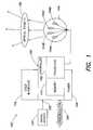
- FIG. 1is a diagram illustrating a lighting unit according to one embodiment of the invention.
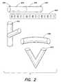
- FIG. 2illustrates exemplary form-factors for the lighting unit of FIG. 1 , based on a substantially linear configuration or curvilinear configuration, according to various embodiments of the invention.
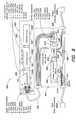
- FIG. 3is a diagram illustrating a networked lighting system according to one embodiment of the invention.
- FIG. 4is a diagram illustrating a network of lighting units each having a linear configuration and disposed in a two-dimensional array, according to one embodiment of the invention.
- FIG. 5shows the array of FIG. 4 , with certain lighting units being indicated as turned on or generating light, according to one embodiment of the invention.
- FIG. 6illustrates a timing diagram for the entire array shown in FIGS. 4 and 5 , or one row of the array, demonstrating that any one of a variety of lighting effects can be created by controlling different lighting units of the array to generate various light outputs over time, according to one embodiment of the invention.
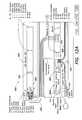
- FIGS. 7 , 8 A, 8 B and 8 Cillustrate various structural aspects of one embodiment of the present invention directed to a modular essentially linear lighting fixture that is configured to house multiple lighting units similar to those discussed above in connection with FIGS. 1-6 .
- FIG. 9illustrates an exemplary arrangement of various components of the linear lighting fixture of FIGS. 7 and 8 , according to one embodiment of the present invention.
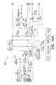
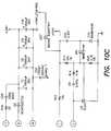
- FIG. 10illustrates a circuit diagram of a switching power supply of the lighting fixture of FIG. 9 , according to one embodiment of the invention.
- FIG. 11illustrates one specific example of an R-G-B lighting unit that may be employed in the lighting fixture of FIG. 9 .
- FIG. 12illustrates an exemplary arrangement of various components of the linear lighting fixture of FIGS. 7 and 8 , according to another embodiment of the present invention.
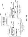
- FIG. 13illustrates a networked lighting system comprising multiple lighting fixtures similar to those shown in FIGS. 9 and 12 , according to one embodiment of the present invention.
- FIG. 1illustrates one example of a lighting unit 100 according to one embodiment of the present invention.
- Some general examples of LED-based lighting units similar to those that are described below in connection with FIG. 1may be found, for example, in U.S. Pat. No. 6,016,038, issued Jan. 18, 2000 to Mueller et al., entitled “Multicolored LED Lighting Method and Apparatus,” and U.S. Pat. No. 6,211,626, issued Apr. 3, 2001 to Lys et al, entitled “Illumination Components,” which patents are both hereby incorporated herein by reference.
- the lighting unit 100 shown in FIG. 1may be used alone or together with other similar lighting units in a system of lighting units (e.g., as discussed further below in connection with FIG. 3 ). Used alone or in combination with other lighting units, the lighting unit 100 may be employed in a variety of applications including, but not limited to, direct-view or indirect-view interior or exterior space (e.g., architectural) lighting and illumination in general, direct or indirect illumination of objects or spaces, theatrical or other entertainment-based/special effects lighting, decorative lighting, safety-oriented lighting, lighting associated with, or illumination of, displays and/or merchandise (e.g. for advertising and/or in retail/consumer environments), combined lighting or illumination and communication systems, etc., as well as for various indication, display and informational purposes.
- direct-view or indirect-view interior or exterior spacee.g., architectural
- lighting and illuminationin general
- direct or indirect illumination of objects or spacese.g., theatrical or other entertainment-based/special effects lighting
- decorative lighting, safety-oriented lightinge.g. for advertising and/
- the lighting unit 100 shown in FIG. 1may include one or more light sources 104 A, 104 B, 104 C, and 104 D (shown collectively as 104 ), wherein one or more of the light sources may be an LED-based light source that includes one or more LEDs. Any two or more of the light sources may be adapted to generate radiation of different colors (e.g. red, green, blue); in this respect, as discussed above, each of the different color light sources generates a different source spectrum that constitutes a different “channel” of a “multi-channel” lighting unit.
- FIG. 1may include one or more light sources 104 A, 104 B, 104 C, and 104 D (shown collectively as 104 ), wherein one or more of the light sources may be an LED-based light source that includes one or more LEDs. Any two or more of the light sources may be adapted to generate radiation of different colors (e.g. red, green, blue); in this respect, as discussed above, each of the different color light sources generates a different source spectrum that constitute
- the lighting unitis not limited in this respect, as different numbers and various types of light sources (all LED-based light sources, LED-based and non-LED-based light sources in combination, etc.) adapted to generate radiation of a variety of different colors, including essentially white light, may be employed in the lighting unit 100 , as discussed further below.
- the lighting unit 100also may include a controller 105 that is configured to output one or more control signals to drive the light sources so as to generate various intensities of light from the light sources.
- the controller 105may be configured to output at least one control signal for each light source so as to independently control the intensity of light (e.g., radiant power in lumens) generated by each light source; alternatively, the controller 105 may be configured to output one or more control signals to collectively control a group of two or more light sources identically.
- control signalsthat may be generated by the controller to control the light sources include, but are not limited to, pulse modulated signals, pulse width modulated signals (PWM), pulse amplitude modulated signals (PAM), pulse code modulated signals (PCM) analog control signals (e.g., current control signals, voltage control signals), combinations and/or modulations of the foregoing signals, or other control signals.
- PWMpulse width modulated signals
- PAMpulse amplitude modulated signals
- PCMpulse code modulated signals
- one or more modulation techniquesprovide for variable control using a fixed current level applied to one or more LEDs, so as to mitigate potential undesirable or unpredictable variations in LED output that may arise if a variable LED drive current were employed.
- the controller 105may control other dedicated circuitry (not shown in FIG. 1 ) which in turn controls the light sources so as to vary their respective intensities.
- the intensity (radiant output power) of radiation generated by the one or more light sourcesis proportional to the average power delivered to the light source(s) over a given time period.
- one technique for varying the intensity of radiation generated by the one or more light sourcesinvolves modulating the power delivered to (i.e., the operating power of) the light source(s). For some types of light sources, including LED-based sources, this may be accomplished effectively using a pulse width modulation (PWM) technique.
- PWMpulse width modulation
- a fixed predetermined voltage V sourceis applied periodically across a given light source constituting the channel.
- the application of the voltage V sourcemay be accomplished via one or more switches, not shown in FIG. 1 , controlled by the controller 105 .
- a predetermined fixed current I sourcee.g., determined by a current regulator, also not shown in FIG. 1
- an LED-based light sourcemay include one or more LEDs, such that the voltage V source may be applied to a group of LEDs constituting the source, and the current I source may be drawn by the group of LEDs.
- the fixed voltage V source across the light source when energized, and the regulated current I source drawn by the light source when energized, determines the amount of instantaneous operating power P source of the light source (P sourceV source ⁇ I source ).
- P sourceV source ⁇ I source
- the controller 105may be configured to apply the voltage V source to a given light source in a pulsed fashion (e.g., by outputting a control signal that operates one or more switches to apply the voltage to the light source), preferably at a frequency that is greater than that capable of being detected by the human eye (e.g., greater than approximately 100 Hz).
- the controllervaries the average amount of time the light source is energized in any given time period, and hence varies the average operating power of the light source. In this manner, the perceived brightness of the generated light from each channel in turn may be varied.
- the controller 105may be configured to control each different light source channel of a multi-channel lighting unit at a predetermined average operating power to provide a corresponding radiant output power for the light generated by each channel.
- the controller 105may receive instructions (e.g., “lighting commands”) from a variety of origins, such as a user interface 118 , a signal source 124 , or one or more communication ports 120 , that specify prescribed operating powers for one or more channels and, hence, corresponding radiant output powers for the light generated by the respective channels.
- instructionse.g., “lighting commands”
- the controller 105may receive instructions (e.g., “lighting commands”) from a variety of origins, such as a user interface 118 , a signal source 124 , or one or more communication ports 120 , that specify prescribed operating powers for one or more channels and, hence, corresponding radiant output powers for the light generated by the respective channels.
- the prescribed operating powers for one or more channelse.g., pursuant to different instructions or lighting commands
- one or more of the light sources 104 A, 104 B, 104 C, and 104 D shown in FIG. 1may include a group of multiple LEDs or other types of light sources (e.g., various parallel and/or serial connections of LEDs or other types of light sources) that are controlled together by the controller 105 .
- one or more of the light sourcesmay include one or more LEDs that are adapted to generate radiation having any of a variety of spectra (i.e., wavelengths or wavelength bands), including, but not limited to, various visible colors (including essentially white light), various color temperatures of white light, ultraviolet, or infrared. LEDs having a variety of spectral bandwidths (e.g., narrow band, broader band) may be employed in various implementations of the lighting unit 100 .
- the lighting unit 100may be constructed and arranged to produce a wide range of variable color radiation.
- the lighting unit 100may be particularly arranged such that controllable variable intensity (i.e., variable radiant power) light generated by two or more of the light sources combines to produce a mixed colored light (including essentially white light having a variety of color temperatures).
- controllable variable intensityi.e., variable radiant power
- the color (or color temperature) of the mixed colored lightmay be varied by varying one or more of the respective intensities (output radiant power) of the light sources (e.g., in response to one or more control signals output by the controller 105 ).
- the controller 105may be particularly configured to provide control signals to one or more of the light sources so as to generate a variety of static or time-varying (dynamic) multi-color (or multi-color temperature) lighting effects.
- the controllermay include a processor 102 (e.g., a microprocessor) programmed to provide such control signals to one or more of the light sources.
- the processor 102may be programmed to provide such control signals autonomously, in response to lighting commands, or in response to various user or signal inputs.
- the lighting unit 100may include a wide variety of colors of LEDs in various combinations, including two or more of red, green, and blue LEDs to produce a color mix, as well as one or more other LEDs to create varying colors and color temperatures of white light.
- red, green and bluecan be mixed with amber, white, UV, orange, IR or other colors of LEDs.
- multiple white LEDs having different color temperaturese.g., one or more first white LEDs that generate a first spectrum corresponding to a first color temperature, and one or more second white LEDs that generate a second spectrum corresponding to a second color temperature different than the first color temperature
- Such combinations of differently colored LEDs and/or different color temperature white LEDs in the lighting unit 100can facilitate accurate reproduction of a host of desirable spectrums of lighting conditions, examples of which include, but are not limited to, a variety of outside daylight equivalents at different times of the day, various interior lighting conditions, lighting conditions to simulate a complex multicolored background, and the like.
- Other desirable lighting conditionscan be created by removing particular pieces of spectrum that may be specifically absorbed, attenuated or reflected in certain environments. Water, for example tends to absorb and attenuate most non-blue and non-green colors of light, so underwater applications may benefit from lighting conditions that are tailored to emphasize or attenuate some spectral elements relative to others.
- the lighting unit 100also may include a memory 114 to store various data.
- the memory 114may be employed to store one or more lighting commands or programs for execution by the processor 102 (e.g., to generate one or more control signals for the light sources), as well as various types of data useful for generating variable color radiation (e.g., calibration information, discussed further below).
- the memory 114also may store one or more particular identifiers (e.g., a serial number, an address, etc.) that may be used either locally or on a system level to identify the lighting unit 100 .
- such identifiersmay be pre-programmed by a manufacturer, for example, and may be either alterable or non-alterable thereafter (e.g., via some type of user interface located on the lighting unit, via one or more data or control signals received by the lighting unit, etc.). Alternatively, such identifiers may be determined at the time of initial use of the lighting unit in the field, and again may be alterable or non-alterable thereafter.
- One issue that may arise in connection with controlling multiple light sources in the lighting unit 100 of FIG. 1 , and controlling multiple lighting units 100 in a lighting systemrelates to potentially perceptible differences in light output between substantially similar light sources.
- the actual intensity of light (e.g., radiant power in lumens) output by each light sourcemay be measurably different.
- Such a difference in light outputmay be attributed to various factors including, for example, slight manufacturing differences between the light sources, normal wear and tear over time of the light sources that may differently alter the respective spectrums of the generated radiation, etc.
- uncalibrated light sourcesfor which a particular relationship between a control signal and resulting output radiant power are not known are referred to as “uncalibrated” light sources.
- the use of one or more uncalibrated light sources in the lighting unit 100 shown in FIG. 1may result in generation of light having an unpredictable, or “uncalibrated,” color or color temperature.
- a first lighting unitincluding a first uncalibrated red light source and a first uncalibrated blue light source, each controlled in response to a corresponding lighting command having an adjustable parameter in a range of from zero to 255 (0-255), wherein the maximum value of 255 represents the maximum radiant power available (i.e., 100%) from the light source.
- red commandis set to zero and the blue command is non-zero, blue light is generated
- blue commandis set to zero and the red command is non-zero
- red lightis generated.
- both commandsare varied from non-zero values, a variety of perceptibly different colors may be produced (e.g., in this example, at very least, many different shades of purple are possible).
- a particular desired colore.g., lavender
- a red command having a value of 125 and a blue command having a value of 200is given by a red command having a value of 125 and a blue command having a value of 200.
- a second lighting unitincluding a second uncalibrated red light source substantially similar to the first uncalibrated red light source of the first lighting unit, and a second uncalibrated blue light source substantially similar to the first uncalibrated blue light source of the first lighting unit.
- the actual intensity of lighte.g., radiant power in lumens
- the actual light output by each blue light sourcemay be measurably different.
- the observed color (or color temperature) of light produced by different lighting units under identical control conditionsmay be perceivably different.
- the “lavender” example abovethe “first lavender” produced by the first lighting unit with a red command having a value of 125 and a blue command having a value of 200 indeed may be perceivably different than a “second lavender” produced by the second lighting unit with a red command having a value of 125 and a blue command having a value of 200.
- the first and second lighting unitsgenerate uncalibrated colors by virtue of their uncalibrated light sources.
- the lighting unit 100includes calibration means to facilitate the generation of light having a calibrated (e.g., predictable, reproducible) color at any given time.
- the calibration meansis configured to adjust (e.g., scale) the light output of at least some light sources of the lighting unit so as to compensate for perceptible differences between similar light sources used in different lighting units.
- the processor 102 of the lighting unit 100is configured to control one or more of the light sources so as to output radiation at a calibrated intensity that substantially corresponds in a predetermined manner to a control signal for the light source(s). As a result of mixing radiation having different spectra and respective calibrated intensities, a calibrated color is produced.
- At least one calibration value for each light sourceis stored in the memory 114 , and the processor is programmed to apply the respective calibration values to the control signals (commands) for the corresponding light sources so as to generate the calibrated intensities.
- One or more calibration valuesmay be determined once (e.g., during a lighting unit manufacturing/testing phase) and stored in the memory 114 for use by the processor 102 .
- the processor 102may be configured to derive one or more calibration values dynamically (e.g. from time to time) with the aid of one or more photosensors, for example.
- the photosensor(s)may be one or more external components coupled to the lighting unit, or alternatively may be integrated as part of the lighting unit itself.
- a photosensoris one example of a signal source that may be integrated or otherwise associated with the lighting unit 100 , and monitored by the processor 102 in connection with the operation of the lighting unit. Other examples of such signal sources are discussed further below, in connection with the signal source 124 shown in FIG. 1 .
- One exemplary method that may be implemented by the processor 102 to derive one or more calibration valuesincludes applying a reference control signal to a light source (e.g., corresponding to maximum output radiant power), and measuring (e.g., via one or more photosensors) an intensity of radiation (e.g., radiant power falling on the photosensor) thus generated by the light source.
- the processormay be programmed to then make a comparison of the measured intensity and at least one reference value (e.g., representing an intensity that nominally would be expected in response to the reference control signal). Based on such a comparison, the processor may determine one or more calibration values (e.g., scaling factors) for the light source. In particular, the processor may derive a calibration value such that, when applied to the reference control signal, the light source outputs radiation having an intensity that corresponds to the reference value (i.e., an “expected” intensity, e.g., expected radiant power in lumens). In various aspects, one calibration value may be derived for an entire range of control signal/output intensities for a given light source.
- multiple calibration valuesmay be derived for a given light source (i.e., a number of calibration value “samples” may be obtained) that are respectively applied over different control signal/output intensity ranges, to approximate a nonlinear calibration function in a piecewise linear manner.
- the lighting unit 100optionally may include one or more user interfaces 118 that are provided to facilitate any of a number of user-selectable settings or functions (e.g., generally controlling the light output of the lighting unit 100 , changing and/or selecting various pre-programmed lighting effects to be generated by the lighting unit, changing and/or selecting various parameters of selected lighting effects, setting particular identifiers such as addresses or serial numbers for the lighting unit, etc.).
- the communication between the user interface 118 and the lighting unitmay be accomplished through wire or cable, or wireless transmission.
- the controller 105 of the lighting unitmonitors the user interface 118 and controls one or more of the light sources 104 A, 104 B, 104 C and 104 D based at least in part on a user's operation of the interface.
- the controller 105may be configured to respond to operation of the user interface by originating one or more control signals for controlling one or more of the light sources.
- the processor 102may be configured to respond by selecting one or more pre-programmed control signals stored in memory, modifying control signals generated by executing a lighting program, selecting and executing a new lighting program from memory, or otherwise affecting the radiation generated by one or more of the light sources.
- the user interface 118may constitute one or more switches (e.g., a standard wall switch) that interrupt power to the controller 105 .
- the controller 105is configured to monitor the power as controlled by the user interface, and in turn control one or more of the light sources based at least in part on duration of a power interruption caused by operation of the user interface.
- the controllermay be particularly configured to respond to a predetermined duration of a power interruption by, for example, selecting one or more pre-programmed control signals stored in memory, modifying control signals generated by executing a lighting program, selecting and executing a new lighting program from memory, or otherwise affecting the radiation generated by one or more of the light sources.
- FIG. 1also illustrates that the lighting unit 100 may be configured to receive one or more signals 122 from one or more other signal sources 124 .
- the controller 105 of the lighting unitmay use the signal(s) 122 , either alone or in combination with other control signals (e.g., signals generated by executing a lighting program, one or more outputs from a user interface, etc.), so as to control one or more of the light sources 104 A, 104 B, 104 C and 104 D in a manner similar to that discussed above in connection with the user interface.
- control signalse.g., signals generated by executing a lighting program, one or more outputs from a user interface, etc.
- Examples of the signal(s) 122 that may be received and processed by the controller 105include, but are not limited to, one or more audio signals, video signals, power signals, various types of data signals, signals representing information obtained from a network (e.g., the Internet), signals representing one or more detectable/sensed conditions, signals from lighting units, signals consisting of modulated light, etc.
- the signal source(s) 124may be located remotely from the lighting unit 100 , or included as a component of the lighting unit. In one embodiment, a signal from one lighting unit 100 could be sent over a network to another lighting unit 100 .
- a signal source 124that may be employed in, or used in connection with, the lighting unit 100 of FIG. 1 include any of a variety of sensors or transducers that generate one or more signals 122 in response to some stimulus.
- sensorsinclude, but are not limited to, various types of environmental condition sensors, such as thermally sensitive (e.g., temperature, infrared) sensors, humidity sensors, motion sensors, photosensors/light sensors (e.g., photodiodes, sensors that are sensitive to one or more particular spectra of electromagnetic radiation such as spectroradiometers or spectrophotometers, etc.), various types of cameras, sound or vibration sensors or other pressure/force transducers (e.g., microphones, piezoelectric devices), and the like.
- thermally sensitivee.g., temperature, infrared
- humidity sensorse.g., humidity sensors, motion sensors, photosensors/light sensors (e.g., photodiodes, sensors that are sensitive to one or more particular spectra of electromagnetic radiation such as
- a signal source 124includes various metering/detection devices that monitor electrical signals or characteristics (e.g., voltage, current, power, resistance, capacitance, inductance, etc.) or chemical/biological characteristics (e.g., acidity, a presence of one or more particular chemical or biological agents, bacteria, etc.) and provide one or more signals 122 based on measured values of the signals or characteristics.
- electrical signals or characteristicse.g., voltage, current, power, resistance, capacitance, inductance, etc.
- chemical/biological characteristicse.g., acidity, a presence of one or more particular chemical or biological agents, bacteria, etc.
- a signal source 124include various types of scanners, image recognition systems, voice or other sound recognition systems, artificial intelligence and robotics systems, and the like.
- a signal source 124could also be a lighting unit 100 , another controller or processor, or any one of many available signal generating devices, such as media players, MP3 players, computers, DVD players, CD players, television signal sources, camera signal sources, microphones, speakers, telephones, cellular phones, instant messenger devices, SMS devices, wireless devices, personal organizer devices, and many others.
- signal generating devicessuch as media players, MP3 players, computers, DVD players, CD players, television signal sources, camera signal sources, microphones, speakers, telephones, cellular phones, instant messenger devices, SMS devices, wireless devices, personal organizer devices, and many others.
- the lighting unit 100 shown in FIG. 1also may include one or more optical elements or facilities 130 to optically process the radiation generated by the light sources 104 A, 104 B, 104 C, and 104 D.
- one or more optical elementsmay be configured so as to change one or both of a spatial distribution and a propagation direction of the generated radiation.
- one or more optical elementsmay be configured to change a diffusion angle of the generated radiation.
- one or more optical elements 130may be particularly configured to variably change one or both of a spatial distribution and a propagation direction of the generated radiation (e.g., in response to some electrical and/or mechanical stimulus).
- optical elementsexamples include, but are not limited to, reflective materials, refractive materials, translucent materials, filters, lenses, mirrors, and fiber optics.
- the optical element 130also may include a phosphorescent material, luminescent material, or other material capable of responding to or interacting with the generated radiation.
- the lighting unit 100may include one or more communication ports 120 to facilitate coupling of the lighting unit 100 to any of a variety of other devices, including one or more other lighting units.
- one or more communication ports 120may facilitate coupling multiple lighting units together as a networked lighting system, in which at least some or all of the lighting units are addressable (e.g., have particular identifiers or addresses) and/or are responsive to particular data transported across the network.
- one or more communication ports 120may be adapted to receive and/or transmit data through wired or wireless transmission.
- information received through the communication portmay at least in part relate to address information to be subsequently used by the lighting unit, and the lighting unit may be adapted to receive and then store the address information in the memory 114 (e.g., the lighting unit may be adapted to use the stored address as its address for use when receiving subsequent data via one or more communication ports).
- the controller 105 of each lighting unit coupled to the networkmay be configured to be responsive to particular data (e.g., lighting control commands) that pertain to it (e.g., in some cases, as dictated by the respective identifiers of the networked lighting units).
- particular datae.g., lighting control commands
- a given controllermay read the data and, for example, change the lighting conditions produced by its light sources according to the received data (e.g., by generating appropriate control signals to the light sources).
- each lighting unit coupled to the networkmay be loaded, for example, with a table of lighting control signals that correspond with data the processor 102 of the controller receives.
- the processormay consult the table to select the control signals that correspond to the received data, and control the light sources of the lighting unit accordingly (e.g., using any one of a variety of analog or digital signal control techniques, including various pulse modulation techniques discussed above).
- the processor 102 of a given lighting unitmay be configured to interpret lighting instructions/data that are received in a DMX protocol (as discussed, for example, in U.S. Pat. Nos. 6,016,038 and 6,211,626), which is a lighting command protocol conventionally employed in the lighting industry for some programmable lighting applications.
- DMX protocollighting instructions are transmitted to a lighting unit as control data that is formatted into packets including 512 bytes of data, in which each data byte is constituted by 8-bits representing a digital value of between zero and 255. These 512 data bytes are preceded by a “start code” byte.
- An entire “packet” including 513 bytes (start code plus data)is transmitted serially at 250 kbit/s pursuant to RS-485 voltage levels and cabling practices, wherein the start of a packet is signified by a break of at least 88 microseconds.
- each data byte of the 512 bytes in a given packetis intended as a lighting command for a particular “channel” of a multi-channel lighting unit, wherein a digital value of zero indicates no radiant output power for a given channel of the lighting unit (i.e., channel off), and a digital value of 255 indicates full radiant output power (100% available power) for the given channel of the lighting unit (i.e., channel full on).
- a lighting command in DMX protocolmay specify each of a red channel command, a green channel command, and a blue channel command as eight-bit data (i.e., a data byte) representing a value from 0 to 255.
- the maximum value of 255 for any one of the color channelsinstructs the processor 102 to control the corresponding light source(s) to operate at maximum available power (i.e., 100%) for the channel, thereby generating the maximum available radiant power for that color (such a command structure for an R-G-B lighting unit commonly is referred to as 24-bit color control).
- a given communication link employing the DMX protocolconventionally can support up to 512 different lighting unit channels.
- a given lighting unit designed to receive communications formatted in the DMX protocolgenerally is configured to respond to only one or more particular data bytes of the 512 bytes in the packet corresponding to the number of channels of the lighting unit (e.g., in the example of a three-channel lighting unit, three bytes are used by the lighting unit), and ignore the other bytes, based on a particular position of the desired data byte(s) in the overall sequence of the 512 data bytes in the packet.
- DMX-based lighting unitsmay be equipped with an address selection mechanism that may be manually set by a user/installer to determine the particular position of the data byte(s) that the lighting unit responds to in a given DMX packet.
- lighting units suitable for purposes of the present disclosureare not limited to a DMX command format, as lighting units according to various embodiments may be configured to be responsive to other types of communication protocols/lighting command formats so as to control their respective light sources.
- the processor 102may be configured to respond to lighting commands in a variety of formats that express prescribed operating powers for each different channel of a multi-channel lighting unit according to some scale representing zero to maximum available operating power for each channel.
- the processor 102 of a given lighting unitmay be configured to interpret lighting instructions/data that are received in a conventional Ethernet protocol (or similar protocol based on Ethernet concepts).
- Ethernetis a well-known computer networking technology often employed for local area networks (LANs) that defines wiring and signaling requirements for interconnected devices forming the network, as well as frame formats and protocols for data transmitted over the network.
- LANslocal area networks
- Devices coupled to the networkhave respective unique addresses, and data for one or more addressable devices on the network is organized as packets.
- Each Ethernet packetincludes a “header” that specifies a destination address (to where the packet is going) and a source address (from where the packet came), followed by a “payload” including several bytes of data (e.g., in Type II Ethernet frame protocol, the payload may be from 46 data bytes to 1500 data bytes).
- a packetconcludes with an error correction code or “checksum.”
- the payload of successive Ethernet packets destined for a given lighting unit configured to receive communications in an Ethernet protocolmay include information that represents respective prescribed radiant powers for different available spectra of light (e.g., different color channels) capable of being generated by the lighting unit.
- the processor 102 of a given lighting unitmay be configured to interpret lighting instructions/data that are received in a serial-based communication protocol as described, for example, in U.S. Pat. No. 6,777,891.
- a serial-based communication protocolmultiple lighting units 100 are coupled together via their communication ports 120 to form a series connection of lighting units (e.g., a daisy-chain or ring topology), wherein each lighting unit has an input communication port and an output communication port. Lighting instructions/data transmitted to the lighting units are arranged sequentially based on a relative position in the series connection of each lighting unit.
- each lighting unit in the series connectionreceives data, it “strips off” or extracts one or more initial portions of the data sequence intended for it and transmits the remainder of the data sequence to the next lighting unit in the series connection.
- the processor 102 of each lighting unit in the series connectionreceives data, it “strips off” or extracts one or more initial portions of the data sequence intended for it and transmits the remainder of the data sequence to the next lighting unit in the series connection.
- three multi-bit valuesone multi-bit value per channel
- each lighting unitmay include respective prescribed radiant powers for different available spectra of light (e.g., different color channels) capable of being generated by the lighting unit.
- each multi-bit value per channelmay be an 8-bit value, or other number of bits (e.g., 12, 16, 24, etc.) per channel, depending in part on a desired control resolution for each channel.
- a flagis associated with each portion of a data sequence representing data for multiple channels of a given lighting unit, and an entire data sequence for multiple lighting units is transmitted completely from lighting unit to lighting unit in the serial connection.
- a lighting unit in the serial connectionreceives the data sequence, it looks for the first portion of the data sequence in which the flag indicates that a given portion (representing one or more channels) has not yet been read by any lighting unit. Upon finding such a portion, the lighting unit reads and processes the portion to provide a corresponding light output, and sets the corresponding flag to indicate that the portion has been read. Again, the entire data sequence is transmitted completely from lighting unit to lighting unit, wherein the state of the flags indicate the next portion of the data sequence available for reading and processing.
- the controller 105 a given lighting unit configured for a serial-based communication protocolmay be implemented as an application-specific integrated circuit (ASIC) designed to specifically process a received stream of lighting instructions/data according to the “data stripping/extraction” process or “flag modification” process discussed above. More specifically, in one exemplary embodiment of multiple lighting units coupled together in a series interconnection to form a network, each lighting unit includes an ASIC-implemented controller 105 having the functionality of the processor 102 , the memory 114 and communication port(s) 120 shown in FIG. 1 (optional user interface 118 and signal source 124 of course need not be included in some implementations). Such an implementation is discussed in detail in U.S. Pat. No. 6,777,891.
- ASICapplication-specific integrated circuit
- the lighting unit 100 of FIG. 1may include and/or be coupled to one or more power sources 108 .
- power source(s) 108include, but are not limited to, AC power sources, DC power sources, batteries, solar-based power sources, thermoelectric or mechanical-based power sources and the like.
- the power source(s) 108may include or be associated with one or more power conversion devices or power conversion circuitry (e.g., in some cases internal to the lighting unit 100 ) that convert power received by an external power source to a form suitable for operation of the various internal circuit components and light sources of the lighting unit 100 .
- power conversion devices or power conversion circuitrye.g., in some cases internal to the lighting unit 100
- the controller 105 of the lighting unit 100may be configured to accept a standard A.C. line voltage from the power source 108 and provide appropriate D.C. operating power for the light sources and other circuitry of the lighting unit based on concepts related to DC-DC conversion, or “switching” power supply concepts.
- the controller 105may include circuitry to not only accept a standard A.C. line voltage but to ensure that power is drawn from the line voltage with a significantly high power factor.
- the lighting unit 100may be implemented in any one of several different structural configurations according to various embodiments of the present disclosure. Examples of such configurations include, but are not limited to, an essentially linear or curvilinear configuration, a circular configuration, an oval configuration, a rectangular configuration, combinations of the foregoing, various other geometrically shaped configurations, various two or three dimensional configurations, and the like.
- FIG. 2illustrates exemplary form-factors for the lighting unit 100 based on a substantially linear configuration 404 or curvilinear configuration 408 , according to one embodiment.
- an essentially linear or elongate housingmay include the one or more light sources 104 A- 104 D, as well as the controller 105 and other components discussed above in connection with FIG. 1 .
- the light sources 104 A- 104 Dmay be disposed in a substantially linear manner on one or more circuit boards within the housing.
- Such a lighting unit having a linear configuration 404 or curvilinear configuration 408can be placed end-to-end with other linear or curvilinear lighting units, or lighting units having other shapes, to produce longer linear lighting systems comprised of multiple lighting units 100 in various shapes.
- housings including integral junctionscan be created with branches, “Ts,” or “Ys” to create a lighting unit having a branched configuration 410
- lighting unitsalso may be implemented with a bent configuration 412 that includes one or more “V” elements.
- Combinations of various configurations including linear configurations 404 , curvilinear configurations 408 , branched configurations 410 and bent configurations 412can be used to create virtually any shape of lighting system, such as one shaped to resemble a letter, number, symbol, logo, object, structure, or the like.
- a given lighting unitalso may have any one of a variety of mounting arrangements for the light source(s), enclosure/housing arrangements and shapes to partially or fully enclose the light sources, and/or electrical and mechanical connection configurations. Additionally, one or more optical elements as discussed above may be partially or fully integrated with an enclosure/housing arrangement for the lighting unit.
- the various components of the lighting unit discussed abovemay be packaged in a variety of ways; for example, in one aspect, any subset or all of the various lighting unit components, as well as other components that may be associated with the lighting unit, may be packaged together. In another aspect, packaged subsets of components may be coupled together electrically and/or mechanically in a variety of manners.
- FIG. 3illustrates an example of a networked lighting system 200 according to one embodiment of the present disclosure.
- a number of lighting units 100similar to those discussed above in connection with FIG. 1 , are coupled together to form the networked lighting system. It should be appreciated, however, that the particular configuration and arrangement of lighting units shown in FIG. 3 is for purposes of illustration only, and that the disclosure is not limited to the particular system topology shown in FIG. 3 .
- the networked lighting system 200may be configured flexibly to include one or more user interfaces, as well as one or more signal sources such as sensors/transducers.
- one or more user interfaces and/or one or more signal sourcessuch as sensors/transducers (as discussed above in connection with FIG. 1 ) may be associated with any one or more of the lighting units of the networked lighting system 200 .
- one or more user interfaces and/or one or more signal sourcesmay be implemented as “stand alone” components in the networked lighting system 200 .
- these devicesmay be “shared” by the lighting units of the networked lighting system.
- one or more user interfaces and/or one or more signal sourcessuch as sensors/transducers may constitute “shared resources” in the networked lighting system that may be used in connection with controlling any one or more of the lighting units of the system.
- the lighting system 200may include one or more lighting unit controllers (hereinafter “LUCs”) 208 A, 208 B, 208 C, and 208 D, wherein each LUC is responsible for communicating with and generally controlling one or more lighting units 100 coupled to it.
- LUCslighting unit controllers
- FIG. 3illustrates two lighting units 100 coupled to the LUC 208 A, and one lighting unit 100 coupled to each LUC 208 B, 208 C and 208 D
- the disclosureis not limited in this respect, as different numbers of lighting units 100 may be coupled to a given LUC in a variety of different configurations (serially connections, parallel connections, combinations of serial and parallel connections, etc.) using a variety of different communication media and protocols.
- each LUCin turn may be coupled to a central controller 202 that is configured to communicate with one or more LUCs.
- FIG. 3shows four LUCs coupled to the central controller 202 via a generic connection 204 (which may include any number of a variety of conventional coupling, switching and/or networking devices), it should be appreciated that according to various embodiments, different numbers of LUCs may be coupled to the central controller 202 .
- the LUCs and the central controllermay be coupled together in a variety of configurations using a variety of different communication media and protocols to form the networked lighting system 200 .
- the interconnection of LUCs and the central controller, and the interconnection of lighting units to respective LUCsmay be accomplished in different manners (e.g., using different configurations, communication media, and protocols).
- the central controller 202 shown in FIG. 3may by configured to implement Ethernet-based communications with the LUCs, and in turn the LUCs may be configured to implement one of Ethernet-based, DMX-based, or serial-based protocol communications with the lighting units 100 (as discussed above, exemplary serial-based protocols suitable for various network implementation are discussed in detail in U.S. Pat. No. 6,777,891.
- each LUCmay be configured as an addressable Ethernet-based controller and accordingly may be identifiable to the central controller 202 via a particular unique address (or a unique group of addresses and/or other identifiers) using an Ethernet-based protocol.
- the central controller 202may be configured to support Ethernet communications throughout the network of coupled LUCs, and each LUC may respond to those communications intended for it.
- each LUCmay communicate lighting control information to one or more lighting units coupled to it, for example, via an Ethernet, DMX, or serial-based protocol, in response to the Ethernet communications with the central controller 202 (wherein the lighting units are appropriately configured to interpret information received from the LUC in the Ethernet, DMX, or serial-based protocols).
- the LUCs 208 A, 208 B, and 208 C shown in FIG. 3may be configured to be “intelligent” in that the central controller 202 may be configured to communicate higher level commands to the LUCs that need to be interpreted by the LUCs before lighting control information can be forwarded to the lighting units 100 .
- a lighting system operatormay want to generate a color changing effect that varies colors from lighting unit to lighting unit in such a way as to generate the appearance of a propagating rainbow of colors (“rainbow chase”), given a particular placement of lighting units with respect to one another.
- the operatormay provide a simple instruction to the central controller 202 to accomplish this, and in turn the central controller may communicate to one or more LUCs using an Ethernet-based protocol high level command to generate a “rainbow chase.”
- the commandmay contain timing, intensity, hue, saturation or other relevant information, for example.
- a given LUCmay then interpret the command and communicate further commands to one or more lighting units using any one of a variety of protocols (e.g., Ethernet, DMX, serial-based), in response to which the respective sources of the lighting units are controlled via any of a variety of signaling techniques (e.g., PWM).
- One or more LUCs of a lighting networkmay be coupled to a series connection of multiple lighting units 100 (e.g., see LUC 208 A of FIG. 3 , which is coupled to two series-connected lighting units 100 ).
- each LUC coupled in this mannercan be configured to communicate with the multiple lighting units using a serial-based communication protocol, examples of which were discussed above.
- a given LUCmay be configured to communicate with a central controller 202 , and/or one or more other LUCs, using an Ethernet-based protocol, and in turn communicate with the multiple lighting units using a serial-based communication protocol.
- a LUCmay be viewed in one sense as a protocol converter that receives lighting instructions or data in the Ethernet-based protocol, and passes on the instructions to multiple serially-connected lighting units using the serial-based protocol.
- a given LUCsimilarly may be viewed as a protocol converter that receives lighting instructions or data in the Ethernet protocol, and passes on instructions formatted in a DMX protocol.
- the foregoing example of using multiple different communication implementations (e.g., Ethernet/DMX) in a lighting system according to one embodiment of the present technologyis for purposes of illustration only, and that the technology is not limited to this particular example.
- one or more lighting units as discussed aboveare capable of generating highly controllable variable color light over a wide range of colors, as well as variable color temperature white light over a wide range of color temperatures.
- FIG. 4shows a network of lighting units 100 having a linear configuration 404 (as discussed above in connection with FIG. 2 ) disposed in a two-dimensional array 700 .
- the lighting units 100may be electrically interconnected to form the networked array shown in FIG. 4 in any of a variety of manners, as discussed above in connection with FIG. 3 .
- lighting units having the linear configuration 404can be physically disposed end-to-end to create an array of arbitrarily large size.
- Lighting units having the linear configuration 404can be of various sizes, such as one foot and four foot segments, or can be uniform in size.
- Each linear lighting unit 100can be individually controlled as discussed above (via a central controller 202 and an appropriate addressing scheme/communication protocol) to provide color, hue, intensity, saturation, and color temperature changes.
- the array 700can present any combination of colors, based on the on and off state, color and intensity of individual linear lighting units of the array 700 .
- FIG. 5shows the array 700 of linear lighting units 100 having the linear configuration 404 , with certain units 100 A turned on (i.e., generating perceivable light output).
- the units 100 A that are turned oncan show the same color, or different colors, under control of a central controller 202 shown in FIG. 3 , for example.
- FIG. 6illustrates a timing diagram for the array 700 of FIGS. 4 and 5 , and shows that any one of a variety of lighting effects can be created by controlling different lighting units of the array to generate various light outputs over time.
- the arrow 902 in FIG. 6shows that as time passes (moving downward in FIG. 6 ), different lighting units 100 A of the array 700 are triggered to turn on.
- the progression of lighting units 100 A turning on over timecould represent a “moving element” of the array 700 , which travels down and across the array and back, apparently following the path of the arrow 904 .
- the timing diagram of FIG. 6can represent a single line of linear lighting units, in which each row illustrated in FIG. 6 represents the same row at a different instant of time.
- the energized lighting unit 100 A in the rowtravels to the right, then back to the left.
- a particular color of lightcan “bounce” back and forth between the ends of a row of linear lighting units, or it can “bounce” around the “walls” of an array (between the ends of a given row).
- the energized lighting unitcan be given attributes, such as simple harmonic motion, a pendulum effect, or the like.
- the “bounce”can be made to obey rules that appear to give it “friction” or “gravity,” (causing the bounce effect to slow down) or “anti-gravity” (causing the bounce effect to accelerate).
- multiple lighting units of a given rowcan also be energized so as to “follow” each other, so that a color chases other colors along the line, or through the array, in a “color chasing rainbow” effect.
- any of the foregoing lighting effects and many otherscan be similarly implemented with other combinations of lighting unit configurations, such as a curvilinear configuration 408 , branched configuration 410 , or bent configuration 412 , as discussed above in connection with FIG. 2 .
- any shape or configuration for a lighting unit 100may substantially resemble a point source if viewed from a great enough distance.
- individual substantially linear lighting units of a larger assembly/array/arrangement, or lighting units having other geometric configurationscan appear like “pixels” on the side of a building, if viewed from a great enough distance.
- FIGS. 7 , 8 A, 8 B and 8 Cillustrate various structural aspects of one embodiment of the present disclosure directed to a modular essentially linear lighting fixture 600 that is configured to house multiple lighting units 100 similar to those discussed above in connection with FIGS. 1-6 .
- the lighting fixture 600may include a housing that includes multiple portions, e.g., a first portion 610 comprising an extruded aluminum portion, over which is disposed a second portion including a substantially linear cylindrical optics casing.
- the first portion 610forms an enclosure containing one or more circuit boards on which various power-related and network-related circuitry are implemented.
- one or more circuit boards on which are disposed multiple lighting units 100may be located within the second portion 620 formed by the optics casing, separated from other power-related and network-related components disposed in the first portion 610 .
- Table 1 belowprovides three exemplary fixture sizes (in length), namely 18 inches, 48 inches, and 96 inches, and provides various exemplary indicated dimensions for the respective fixture sizes. While three possible fixture sizes are indicated in Table 1, it should be appreciated that lighting fixtures 600 according to the present invention are not necessarily limited in this respect, as the dimensions indicated in FIG. 8 are provided primarily for purposes of illustration, and other dimensions are possible.
- FIG. 9illustrates an exemplary arrangement of various components of the linear lighting fixture 600 of FIGS. 7 and 8 , according to one embodiment of the present disclosure.
- a power and control circuit board 550 of the lighting fixture 600is disposed in a first portion 610 of the fixture (e.g., an extruded aluminum portion).
- FIG. 9also shows that three modular LED circuit boards 520 A, 520 B and 520 C are disposed in a second portion 620 of the fixture generally enclosed by the optics casing, wherein each LED circuit board 520 A-C includes five multi-channel lighting units 100 .
- An input connector 560 A and an output connector 560 Bcarry power from a power source and lighting instructions (i.e., lighting commands or data) to and from the lighting fixture 600 , such that multiple lighting fixtures may be coupled together to form a networked lighting system.
- the connectors 560 A,Binclude a passageway that allows power and/or data lines to exit the housing at a location other than the end of the housing.
- the connectors 560 A, 560 Bare configured and disposed at the first portion 610 of the housing such that two or more lighting fixtures 600 can be connected end-to-end without a gap between the second portions 620 of their housings, and, therefore, without visual interruption of the perceived light emission from the adjoined fixtures.
- the lighting fixture 600is configured to receive a source of operating power 108 via the input connector 560 A in the form of a standard/conventional A.C. line voltage (e.g., 120 Vrms-240 Vrms).
- This A.C. line voltagealso is connected directly to the output connector 560 B for provision to one or more other lighting fixtures in turn that may be coupled in a daisy-chain fashion to the lighting fixture 600 .
- the A.C. line voltageis connected to the power and control circuit board 550 , which includes a power factor corrected switching power supply 530 (e.g., based on a DC-DC converter) that provides a D.C.
- the switching power supply 530may be configured to provide a D.C. output voltage on the order of approximately 20 Volts (e.g., 24 VDC) and capable of providing approximately 20 Watts of power.
- a circuit diagram of a switching power supply 530 according to one exemplary implementationis shown in FIG. 10 .
- the lighting fixture 600is configured to receive lighting instructions/data for the multiple lighting units of the fixture using an Ethernet-based protocol.
- both the input connector 560 A and the output connector 560 Bare coupled to transmit and receive twisted wire pairs 515 to carry Ethernet-based communications to and from the power and control board 550 of the lighting fixture 600 .
- the wire pairs 515 carrying the Ethernet-based communicationsare coupled to a lighting unit controller or LUC 208 , similar to that discussed above in connection with FIG. 3 , which forms part of the power and control circuit board 550 shown in FIG. 9 .
- the LUC 208is configured to process the Ethernet-based communications and in turn communicate with the multiple lighting units 100 of the fixture 600 using a serial-based communication protocol, examples of which were discussed above. Accordingly, the LUC 208 essentially functions as a communication protocol converter that receives lighting instructions or data in the Ethernet-based protocol, and passes on the instructions to the multiple lighting units of the fixture using the serial-based protocol.
- the LUC 208 shown in FIG. 9includes an Ethernet switch 510 that is configured to handle incoming Ethernet-based packet traffic to the fixture 600 .
- the Ethernet switchis configured such that packet traffic may be communicated to and from the fixture at 100 Mbs/sec.
- the LUC 208 of the lighting fixture 600is assigned a unique MAC/IP address (and perhaps other unique identifiers such as a serial number and a device name), and the Ethernet switch 510 is configured to identify particular packets in the incoming packet traffic that are specifically intended for the lighting fixture 600 (based on the address and/or other unique identifiers for the lighting fixture).
- the LUC 208also includes a microprocessor 570 that receives from the Ethernet switch 510 the particular packets intended for the lighting fixture.
- the microprocessor 570may include a built-in 10 Mb Ethernet interface via which the microprocessor and the Ethernet switch are coupled.
- the microprocessor 570extracts, from the Ethernet packets it receives, lighting instructions/data for the multiple lighting units of the fixture, and in turn transmits these lighting instructions/data to the lighting units using a serial-based protocol.
- DC operating power for the multiple lighting units 100 of the lighting fixture 600are provided from the power and control circuit board 550 to a first LED circuit board 520 A via a wire bundle 540 .
- the wire bundle 540has one terminus coupled to the power and control board 550 via an 8-pin connector 545 and another terminus coupled to the first LED circuit board 520 A via an 11-pin solder connection.
- the LED circuit boards 520 A, 520 B and 520are modular in nature and include mating and/or interlocking connectors 555 (e.g., 9-pin Samtec connectors) to permit modular serial interconnections of multiple LED circuit boards within a given lighting fixture.
- the LED-based lighting units 100are disposed on the modular circuit boards 520 A, 520 B and 520 C such that they are spaced apart from each other at a distance of approximately one inch.
- each of the LED circuit boards 520 A, 520 B and 520 C shown in FIG. 9is approximately six inches long and includes five individually controllable lighting units 100 (thereby providing a control resolution within each lighting fixture 600 of approximately 1.2 inches). This precise level of control allows the fixtures 600 to run video, graphics and intricately designed effects in a host of architectural and entertainment settings.
- each of the lighting units 100may be a three channel R-G-B lighting unit.
- FIG. 11illustrates one specific example of an R-G-B lighting unit 100 representative of the lighting units of a given LED circuit board, in which a red channel of each lighting unit includes nine red LEDs 104 R connected in series, a green channel includes five green LEDs 104 G connected in series, and a blue channel includes five blue LEDs 104 B connected in series.
- a red channel of each lighting unitincludes nine red LEDs 104 R connected in series
- a green channelincludes five green LEDs 104 G connected in series
- a blue channelincludes five blue LEDs 104 B connected in series.
- the controller 105 of each lighting unit 100may be implemented as an application-specific integrated circuit (ASIC) designed to specifically process a stream of lighting instructions/data received at an input communication port 120 IN according to the “data stripping/extraction” process or “flag modification” process discussed above in connection with exemplary serial-based communication protocols, and pass on a stream of lighting instructions/data via an output communication port 120 OUT to a subsequent lighting unit in a series interconnection.
- ASICapplication-specific integrated circuit
- each LED circuit board 520 A, 520 B and 520 Care coupled together in a series interconnection, and the circuit boards are in turn also coupled together in a series interconnection via the connectors 555 , such that the entire collection of fifteen lighting units are serially-interconnected, wherein each lighting unit includes an ASIC-implemented controller 105 having the functionality of the processor 102 , the memory 114 and communication port(s) 120 shown in FIG. 1 .
- FIG. 12illustrates an exemplary arrangement of various components of the linear lighting fixture 600 of FIGS. 7 and 8 , according to another embodiment of the present disclosure.
- the fixture shown in FIG. 12is a larger version of that shown in FIG. 9 , in which eight modular LED circuit boards 520 are disposed in an area of the fixture generally enclosed by the optics casing 610 , and wherein two power and control circuit boards 550 A and 550 B are disposed in an area of the fixture generally defined by the aluminum housing 620 .
- the power and control circuit boards 550 A and 550 Bare modular in nature.
- each LED board 520consumes approximately 4 Watts of power, and each switching power supply 520 provides approximately 20 Watts of power; accordingly, a fixture with eight LED circuit boards 520 requires two switching power supplies 530 ).
- FIG. 13illustrates a networked lighting system 1000 comprising multiple lighting fixtures 600 similar to those shown in FIGS. 9 and 12 , according to one embodiment of the present invention.
- the lighting system 1000shares some features of the lighting network discussed above in connection with FIG. 3 , wherein each of the lighting fixtures 600 includes a LUC 208 and multiple lighting units 100 .
- a central controller 202is coupled via an Ethernet switch 204 to multiple power/data junction boxes 800 which accept power 108 from a standard A.C.
- the central controllermay be implemented as a “light system manager” or a “video system manager” as described in detail in U.S. Patent Application Publication No. 2005-0248299, published Nov. 10, 2005, entitled “Light System Manager;” to provide precision lighting control of each lighting unit within each lighting fixture 600 of the system 1000 .
- this precise level of controlallows the fixtures 600 to run video, graphics and intricately designed effects in a host of architectural and entertainment settings.
- the lighting fixturesmay be arranged in one or two-dimensional arrays (as shown for example in FIGS. 4-6 ), wherein each lighting unit of each lighting fixture may be controlled to provide a wide variety of lighting effects (e.g., in one example, with a controllable resolution of 1.2 inch increments as discussed above in connection with FIG. 9 ).
- a two-dimensional array formed by multiple lighting fixtures 600 of the system 1000also may provide a large scale text, graphics, and/or video reproduction system, in which each lighting unit of a given lighting fixture, or groups of lighting units, may be controlled as individual pixels of a display to reproduce text, graphics, and/or video content.
- the lighting system 1000also may be flexibly deployed in a three-dimensional environment, for example, on multiple sides of a building, as well as outlining all or a portion of a perimeter of a building or various architectural features of other interior or exterior spaces, to provide controllable multi-color lighting in these environments. Also, as discussed above in connection with FIG. 2 , it should be appreciated that lighting fixtures similar to those discussed herein in connection with FIGS. 9 and 12 may be implemented with other form factors, such as curvilinear configurations, branched configurations, v-configurations, and the like, to provide a wide variety of system implementation possibilities in a number of environments.
- a reference to “A and/or B”, when used in conjunction with open-ended language such as “comprising”can refer, in one embodiment, to A only (optionally including elements other than B); in another embodiment, to B only (optionally including elements other than A); in yet another embodiment, to both A and B (optionally including other elements); etc.
- the phrase “at least one,” in reference to a list of one or more elements,should be understood to mean at least one element selected from any one or more of the elements in the list of elements, but not necessarily including at least one of each and every element specifically listed within the list of elements and not excluding any combinations of elements in the list of elements.
- This definitionalso allows that elements may optionally be present other than the elements specifically identified within the list of elements to which the phrase “at least one” refers, whether related or unrelated to those elements specifically identified.
- “at least one of A and B”can refer, in one embodiment, to at least one, optionally including more than one, A, with no B present (and optionally including elements other than B); in another embodiment, to at least one, optionally including more than one, B, with no A present (and optionally including elements other than A); in yet another embodiment, to at least one, optionally including more than one, A, and at least one, optionally including more than one, B (and optionally including other elements); etc.
Landscapes
- Circuit Arrangement For Electric Light Sources In General (AREA)
- Dc-Dc Converters (AREA)
- Non-Portable Lighting Devices Or Systems Thereof (AREA)
- Arrangement Of Elements, Cooling, Sealing, Or The Like Of Lighting Devices (AREA)
Abstract
Description
- U.S. Pat. No. 6,016,038, issued Jan. 18, 2000, entitled “Multicolored LED Lighting Method and Apparatus;”
- U.S. Pat. No. 6,211,626, issued Apr. 3, 2001, entitled “Illumination Components;”
- U.S. Pat. No. 6,608,453, issued Aug. 19, 2003, entitled “Methods and Apparatus for Controlling Devices in a Networked Lighting System;”
- U.S. Pat. No. 6,777,891 issued Aug. 17, 2004, entitled “Methods and Apparatus for Controlling Devices in a Networked Lighting System;”
- U.S. Pat. No. 6,717,376, issued Apr. 6, 2004, entitled “Automotive Information Systems;”
- U.S. Pat. No. 7,161,311, issued Jan. 9, 2007, entitled “Multicolored LED Lighting Method and Apparatus;”
- U.S. Pat. No. 7,202,613, issued Apr. 10, 2007, entitled “Controlled Lighting Methods and Apparatus;”
- U.S. Pat. No. 7,233,115, issued Jun. 19, 2007, entitled “LED-Based Lighting Network Power Control Methods and Apparatus;”
- U.S. Patent Application Publication No. 2005-0213353, filed Sep. 29, 2005, entitled “LED Power Control Methods and Apparatus;”
- U.S. Patent Application Publication No. 2005-0248299, published Nov. 10, 2005, entitled “Light System Manager;”
- U.S. Patent Application Publication No. 2006-0002110, published Jan. 5, 2006, entitled “Methods and Systems for Providing Lighting Systems;” and
- U.S. Patent Application Publication No. 2007-0188114, published Aug. 17, 2007, entitled “Methods and Apparatus for High Power Factor Controlled Power Delivery Using a Single Switching Stage Per Load.”
| TABLE 1 | ||||||
| #Fastening | ||||||
| Fixture Size | Locations Per | Weight | ||||
| (in/cm) | A (in/cm) | B (in/cm) | C (in/cm) | D (in/cm) | Fixture | (lb/kg) |
| 18/45.72 | 0.13/0.33 | 3.63/9.22 | 10.88/27.64 | 12.38/31.45 | 6 | 3.4/1.5 |
| 48/121.92 | 0.38/0.97 | 8.06/20.47 | 16.13/40.97 | 42.38/107.65 | 10 | 9.3/4/2 |
| 96/242.84 | 0.50/1.27 | 12.06/30.63 | 24.13/61.29 | 90.38/229.57 | 14 | 19.0/8.6 |
Claims (12)
Priority Applications (1)
| Application Number | Priority Date | Filing Date | Title |
|---|---|---|---|
| US11/875,196US7961113B2 (en) | 2006-10-19 | 2007-10-19 | Networkable LED-based lighting fixtures and methods for powering and controlling same |
Applications Claiming Priority (2)
| Application Number | Priority Date | Filing Date | Title |
|---|---|---|---|
| US86218306P | 2006-10-19 | 2006-10-19 | |
| US11/875,196US7961113B2 (en) | 2006-10-19 | 2007-10-19 | Networkable LED-based lighting fixtures and methods for powering and controlling same |
Publications (2)
| Publication Number | Publication Date |
|---|---|
| US20080094005A1 US20080094005A1 (en) | 2008-04-24 |
| US7961113B2true US7961113B2 (en) | 2011-06-14 |
Family
ID=39199055
Family Applications (1)
| Application Number | Title | Priority Date | Filing Date |
|---|---|---|---|
| US11/875,196Active2029-10-16US7961113B2 (en) | 2006-10-19 | 2007-10-19 | Networkable LED-based lighting fixtures and methods for powering and controlling same |
Country Status (9)
| Country | Link |
|---|---|
| US (1) | US7961113B2 (en) |
| EP (1) | EP2087776B1 (en) |
| JP (1) | JP2010507218A (en) |
| KR (1) | KR20090096429A (en) |
| CN (1) | CN101589650B (en) |
| ES (1) | ES2530429T3 (en) |
| PL (1) | PL2087776T3 (en) |
| RU (1) | RU2483498C2 (en) |
| WO (1) | WO2008051464A1 (en) |
Cited By (49)
| Publication number | Priority date | Publication date | Assignee | Title |
|---|---|---|---|---|
| US20100013396A1 (en)* | 2008-07-15 | 2010-01-21 | Peng Wen-Chi | Led control system using modulated signal |
| US20110090681A1 (en)* | 2009-10-19 | 2011-04-21 | Hobson Charles O | Housing for a LED Lighting System |
| US20120280637A1 (en)* | 2008-09-18 | 2012-11-08 | Lumastream Canada Ulc | Configurable led driver/dimmer for solid state lighting applications |
| US8319452B1 (en) | 2012-01-05 | 2012-11-27 | Lumenpulse Lighting, Inc. | Dimming protocol detection for a light fixture |
| US20130026934A1 (en)* | 2011-07-29 | 2013-01-31 | Stefanoff Dana D | Led control module |
| US8439757B2 (en) | 2011-10-12 | 2013-05-14 | Cepia, Llc | Interactive entertainment devices interchangeably arrangable in adjacent manner |
| US20130141007A1 (en)* | 2011-12-02 | 2013-06-06 | Tyco Electronics Corporation | Modular led power system with configurable control interface |
| US20130169178A1 (en)* | 2011-12-29 | 2013-07-04 | Semisilicon Technology Corp. | Light emitting diode control system using modulated signals |
| USD691751S1 (en) | 2012-01-17 | 2013-10-15 | Geee Creations, Inc. | Lamp tube |
| USD696812S1 (en) | 2012-01-17 | 2013-12-31 | Geee Creations, Inc. | Lamp holder |
| US8742694B2 (en) | 2011-03-11 | 2014-06-03 | Ilumi Solutions, Inc. | Wireless lighting control system |
| US8810359B2 (en) | 2010-06-23 | 2014-08-19 | Lumenpulse Lighting, Inc. | Assembling and controlling light unit arrays |
| US8851704B2 (en) | 2012-01-06 | 2014-10-07 | Geee Creations, Inc. | Seamless connecting shell and lighting device using the same |
| US8912905B2 (en) | 2011-02-28 | 2014-12-16 | Chon Meng Wong | LED lighting system |
| US8994282B1 (en)* | 2013-12-16 | 2015-03-31 | Semisilicon Technology Corp. | Light emitting diode control circuit with synchronization signal and package structure for the same and system for the same |
| US9049759B2 (en) | 2008-09-18 | 2015-06-02 | Lumastream Canada Ulc | Configurable LED driver/dimmer for solid state lighting applications |
| US9060395B1 (en)* | 2014-03-19 | 2015-06-16 | Semisilicon Technology Corp. | Light emitting diode driving system |
| US20160007421A1 (en)* | 2013-02-19 | 2016-01-07 | Lighting Intelligence, S.L. | Lighting device and method for managing a lighting system |
| US9559519B2 (en) | 2009-07-15 | 2017-01-31 | Yehuda Binder | Sequentially operated modules |
| US9635733B2 (en) | 2012-05-04 | 2017-04-25 | Lumenpulse Lighting, Inc. | Automatic light fixture address system and method |
| US9655211B2 (en) | 2013-09-23 | 2017-05-16 | Seasonal Specialties, Llc | Lighting |
| US9696005B2 (en) | 2012-05-06 | 2017-07-04 | Lighting Science Group Corporation | Tunable lighting apparatus |
| US9699862B2 (en) | 2012-05-07 | 2017-07-04 | Lumenpulse Lighting, Inc. | Power line non-lighting application controller system and method |
| US9995444B2 (en) | 2011-10-17 | 2018-06-12 | Ecosense Lighting Inc. | Linear LED light housing |
| CN108208937A (en)* | 2017-12-13 | 2018-06-29 | 常州市派腾电子技术服务有限公司 | Control method, control device and the electronic cigarette of electronic cigarette |
| US10136503B2 (en)* | 2012-10-15 | 2018-11-20 | Chia-Teh Chen | Microcontroller-based multifunctional electronic switch and lighting apparatus having the same |
| US10149439B2 (en) | 2014-12-18 | 2018-12-11 | Spectra Harvest Lighting, LLC | LED grow light system |
| US10321541B2 (en) | 2011-03-11 | 2019-06-11 | Ilumi Solutions, Inc. | LED lighting device |
| US10339796B2 (en) | 2015-07-07 | 2019-07-02 | Ilumi Sulutions, Inc. | Wireless control device and methods thereof |
| US10477659B1 (en) | 2016-09-15 | 2019-11-12 | Apple Inc. | Adjustable lighting systems |
| US10509159B2 (en) | 2016-08-22 | 2019-12-17 | Samsung Electronics Co., Ltd. | Light source module and backlight assembly having the same |
| US10537001B2 (en) | 2007-10-06 | 2020-01-14 | Lynk Labs, Inc. | Multi-voltage and multi-brightness LED lighting devices and methods of using same |
| US10624182B2 (en) | 2012-07-01 | 2020-04-14 | Ideal Industries Lighting Llc | Master/slave arrangement for lighting fixture modules |
| US10630820B2 (en) | 2011-03-11 | 2020-04-21 | Ilumi Solutions, Inc. | Wireless communication methods |
| US10660175B2 (en) | 2013-09-23 | 2020-05-19 | Seasonal Specialties, Llc | Lighting |
| US10731831B2 (en) | 2017-05-08 | 2020-08-04 | Gemmy Industries Corp. | Clip lights and related systems |
| US10801714B1 (en) | 2019-10-03 | 2020-10-13 | CarJamz, Inc. | Lighting device |
| US10989372B2 (en) | 2017-03-09 | 2021-04-27 | Ecosense Lighting Inc. | Fixtures and lighting accessories for lighting devices |
| US11022279B2 (en) | 2016-03-08 | 2021-06-01 | Ecosense Lighting Inc. | Lighting system with lens assembly |
| US11028980B2 (en) | 2013-10-30 | 2021-06-08 | Ecosense Lighting Inc. | Flexible strip lighting apparatus and methods |
| US11041609B2 (en) | 2018-05-01 | 2021-06-22 | Ecosense Lighting Inc. | Lighting systems and devices with central silicone module |
| US11218579B2 (en) | 2015-07-07 | 2022-01-04 | Ilumi Solutions, Inc. | Wireless communication methods |
| US11244558B2 (en) | 2013-09-23 | 2022-02-08 | Seasonal Specialties, Llc | Lighting |
| US11296057B2 (en) | 2017-01-27 | 2022-04-05 | EcoSense Lighting, Inc. | Lighting systems with high color rendering index and uniform planar illumination |
| US11297705B2 (en) | 2007-10-06 | 2022-04-05 | Lynk Labs, Inc. | Multi-voltage and multi-brightness LED lighting devices and methods of using same |
| US11353200B2 (en) | 2018-12-17 | 2022-06-07 | Korrus, Inc. | Strip lighting system for direct input of high voltage driving power |
| US11849512B2 (en) | 2012-07-01 | 2023-12-19 | Ideal Industries Lighting Llc | Lighting fixture that transmits switch module information to form lighting networks |
| US11978336B2 (en) | 2015-07-07 | 2024-05-07 | Ilumi Solutions, Inc. | Wireless control device and methods thereof |
| US12388056B1 (en) | 2017-01-27 | 2025-08-12 | Korrus, Inc. | Linear lighting systems and processes |
Families Citing this family (101)
| Publication number | Priority date | Publication date | Assignee | Title |
|---|---|---|---|---|
| US10499465B2 (en) | 2004-02-25 | 2019-12-03 | Lynk Labs, Inc. | High frequency multi-voltage and multi-brightness LED lighting devices and systems and methods of using same |
| US10575376B2 (en) | 2004-02-25 | 2020-02-25 | Lynk Labs, Inc. | AC light emitting diode and AC LED drive methods and apparatus |
| WO2011143510A1 (en) | 2010-05-12 | 2011-11-17 | Lynk Labs, Inc. | Led lighting system |
| US20050259424A1 (en) | 2004-05-18 | 2005-11-24 | Zampini Thomas L Ii | Collimating and controlling light produced by light emitting diodes |
| US7766511B2 (en)* | 2006-04-24 | 2010-08-03 | Integrated Illumination Systems | LED light fixture |
| US7729941B2 (en) | 2006-11-17 | 2010-06-01 | Integrated Illumination Systems, Inc. | Apparatus and method of using lighting systems to enhance brand recognition |
| US8013538B2 (en) | 2007-01-26 | 2011-09-06 | Integrated Illumination Systems, Inc. | TRI-light |
| US8742686B2 (en)* | 2007-09-24 | 2014-06-03 | Integrated Illumination Systems, Inc. | Systems and methods for providing an OEM level networked lighting system |
| US11317495B2 (en) | 2007-10-06 | 2022-04-26 | Lynk Labs, Inc. | LED circuits and assemblies |
| US10986714B2 (en) | 2007-10-06 | 2021-04-20 | Lynk Labs, Inc. | Lighting system having two or more LED packages having a specified separation distance |
| US8255487B2 (en)* | 2008-05-16 | 2012-08-28 | Integrated Illumination Systems, Inc. | Systems and methods for communicating in a lighting network |
| US20100262296A1 (en)* | 2008-06-25 | 2010-10-14 | HID Laboratories, Inc. | Lighting control system and method |
| US8143811B2 (en)* | 2008-06-25 | 2012-03-27 | Lumetric, Inc. | Lighting control system and method |
| US9018858B2 (en) | 2008-09-24 | 2015-04-28 | B/E Aerospace, Inc. | Calibration method for LED lighting systems |
| US8159149B2 (en)* | 2008-10-24 | 2012-04-17 | Honeywell International Inc. | Systems and methods for security controlled LED lighting fixture |
| US8257119B2 (en)* | 2008-12-19 | 2012-09-04 | Honeywell International | Systems and methods for affixing a silicon device to a support structure |
| CN101769451B (en)* | 2008-12-29 | 2012-03-14 | 富准精密工业(深圳)有限公司 | LED lamps |
| US8231245B2 (en)* | 2009-02-13 | 2012-07-31 | Dialight Corporation | LED lighting fixture |
| US8145327B2 (en)* | 2009-03-13 | 2012-03-27 | Susan Banks | Method and apparatus for implementing a consumer-configurable modular electrical system |
| US8585245B2 (en) | 2009-04-23 | 2013-11-19 | Integrated Illumination Systems, Inc. | Systems and methods for sealing a lighting fixture |
| EP2256720A1 (en) | 2009-05-29 | 2010-12-01 | Koninklijke Philips Electronics N.V. | An intelligent lighting tile system powered from multiple power sources |
| EP2257127A1 (en)* | 2009-05-29 | 2010-12-01 | Koninklijke Philips Electronics N.V. | Method for data path creation in a modular lighting system |
| US8740701B2 (en) | 2009-06-15 | 2014-06-03 | Wms Gaming, Inc. | Controlling wagering game system audio |
| WO2011005797A1 (en) | 2009-07-07 | 2011-01-13 | Wms Gaming, Inc. | Controlling gaming effects for gaming network nodes |
| WO2011005798A1 (en) | 2009-07-07 | 2011-01-13 | Wms Gaming, Inc. | Controlling wagering game lighting content |
| US10269207B2 (en) | 2009-07-31 | 2019-04-23 | Bally Gaming, Inc. | Controlling casino lighting content and audio content |
| US9011247B2 (en) | 2009-07-31 | 2015-04-21 | Wms Gaming, Inc. | Controlling casino lighting content and audio content |
| US20110042137A1 (en)* | 2009-08-18 | 2011-02-24 | Honeywell International Inc. | Suspended lead frame electronic package |
| US8622830B2 (en)* | 2009-08-20 | 2014-01-07 | Wms Gaming, Inc. | Controlling sound distribution in wagering game applications |
| US8613667B2 (en) | 2009-12-21 | 2013-12-24 | Wms Gaming, Inc. | Position-based lighting coordination in wagering game systems |
| US12279345B2 (en) | 2009-12-28 | 2025-04-15 | Lynk Labs, Inc. | Light emitting diode and LED drive apparatus |
| EP2539227A4 (en)* | 2010-02-25 | 2014-04-02 | Be Aerospace Inc | An aircraft led washlight system and method for controlling same |
| US9091422B2 (en) | 2010-02-25 | 2015-07-28 | B/E Aerospace, Inc. | LED lighting element |
| US8814673B1 (en) | 2010-04-26 | 2014-08-26 | Wms Gaming, Inc. | Presenting lighting content in wagering game systems |
| US9367987B1 (en) | 2010-04-26 | 2016-06-14 | Bally Gaming, Inc. | Selecting color in wagering game systems |
| US8840464B1 (en) | 2010-04-26 | 2014-09-23 | Wms Gaming, Inc. | Coordinating media in a wagering game environment |
| US8760462B2 (en)* | 2010-05-06 | 2014-06-24 | Columbia Insurance Company | Color management method for color representation with self-luminous color primaries |
| US8912727B1 (en) | 2010-05-17 | 2014-12-16 | Wms Gaming, Inc. | Wagering game lighting device chains |
| US8646941B1 (en) | 2010-06-14 | 2014-02-11 | Humanscale Corporation | Lighting apparatus and method |
| JP2013535076A (en)* | 2010-06-18 | 2013-09-09 | ビーイー・エアロスペース・インコーポレーテッド | Modular light emitting diode system for vehicle lighting |
| BR112012033224A2 (en)* | 2010-06-29 | 2016-11-16 | Lumetric Lighting Inc | lighting control method and system |
| US8827805B1 (en) | 2010-08-06 | 2014-09-09 | Wms Gaming, Inc. | Balancing community gaming effects |
| CN103249988B (en)* | 2010-12-16 | 2016-10-12 | 皇家飞利浦电子股份有限公司 | LED-based assembly |
| US9066381B2 (en) | 2011-03-16 | 2015-06-23 | Integrated Illumination Systems, Inc. | System and method for low level dimming |
| US9967940B2 (en) | 2011-05-05 | 2018-05-08 | Integrated Illumination Systems, Inc. | Systems and methods for active thermal management |
| GB201108802D0 (en)* | 2011-05-25 | 2011-07-06 | Benmore Ventures Ltd | Modular lighting systems |
| LT5918B (en)* | 2011-07-12 | 2013-03-25 | Vilniaus Universitetas | Polychromatic solid-staye light sources for the control of colour saturation of illuminated surfaces |
| US9521725B2 (en) | 2011-07-26 | 2016-12-13 | Hunter Industries, Inc. | Systems and methods for providing power and data to lighting devices |
| US10874003B2 (en) | 2011-07-26 | 2020-12-22 | Hunter Industries, Inc. | Systems and methods for providing power and data to devices |
| US8710770B2 (en) | 2011-07-26 | 2014-04-29 | Hunter Industries, Inc. | Systems and methods for providing power and data to lighting devices |
| US20150237700A1 (en) | 2011-07-26 | 2015-08-20 | Hunter Industries, Inc. | Systems and methods to control color and brightness of lighting devices |
| US9609720B2 (en) | 2011-07-26 | 2017-03-28 | Hunter Industries, Inc. | Systems and methods for providing power and data to lighting devices |
| US11917740B2 (en) | 2011-07-26 | 2024-02-27 | Hunter Industries, Inc. | Systems and methods for providing power and data to devices |
| US20140239809A1 (en) | 2011-08-18 | 2014-08-28 | Lynk Labs, Inc. | Devices and systems having ac led circuits and methods of driving the same |
| EP2749140B1 (en)* | 2011-10-25 | 2018-05-09 | Philips Lighting Holding B.V. | Methods for controlling a lighting fixture utilizing a communication protocol |
| WO2013082609A1 (en) | 2011-12-02 | 2013-06-06 | Lynk Labs, Inc. | Color temperature controlled and low thd led lighting devices and systems and methods of driving the same |
| JP2013179018A (en)* | 2012-02-12 | 2013-09-09 | Naoyuki Murakami | Led illumination lamp with calculation function |
| US8581513B1 (en) | 2012-04-20 | 2013-11-12 | Leilani Reinaso | Battery powered wireless DMX led lighting system |
| US8558413B1 (en)* | 2012-07-09 | 2013-10-15 | Global Green Lighting, LLC | Light fixture having power over ethernet power sourcing equipment |
| US8894437B2 (en) | 2012-07-19 | 2014-11-25 | Integrated Illumination Systems, Inc. | Systems and methods for connector enabling vertical removal |
| EP3307028B1 (en)* | 2012-07-20 | 2021-04-07 | Signify Holding B.V. | Methods and apparatus for adaptable lighting unit |
| US9379578B2 (en) | 2012-11-19 | 2016-06-28 | Integrated Illumination Systems, Inc. | Systems and methods for multi-state power management |
| US9554444B2 (en) | 2012-12-17 | 2017-01-24 | OV20 Systems | Device and method for retrofitting or converting or adapting series circuits |
| US9420665B2 (en) | 2012-12-28 | 2016-08-16 | Integration Illumination Systems, Inc. | Systems and methods for continuous adjustment of reference signal to control chip |
| US9485814B2 (en) | 2013-01-04 | 2016-11-01 | Integrated Illumination Systems, Inc. | Systems and methods for a hysteresis based driver using a LED as a voltage reference |
| KR101386203B1 (en)* | 2013-01-09 | 2014-04-21 | 광주대학교산학협력단 | Protocol converter for light control |
| DE102013203021A1 (en)* | 2013-01-23 | 2014-08-07 | io-consultants GmbH & Co. KG | Lighting device, has current source, lighting unit and function units arranged between current source and lighting unit and mechanically, electrically and/or optically combined with one another under consideration of specific function |
| US9210768B2 (en)* | 2013-02-15 | 2015-12-08 | Osram Sylvania Inc. | Illumination techniques and devices |
| CN104238383A (en)* | 2013-06-17 | 2014-12-24 | 欧司朗有限公司 | Control system and method for controlling control system |
| ES2762121T3 (en)* | 2013-08-19 | 2020-05-22 | Signify Holding Bv | Programmable lighting fixture and lighting fixture programming procedure and system |
| US9655207B2 (en)* | 2013-08-27 | 2017-05-16 | Philips Lighting Holding B.V. | Sensor network with adaptive detection settings based on the status information from neighboring luminaires and/or connected devices |
| DE102013113053B4 (en)* | 2013-11-26 | 2019-03-28 | Schott Ag | Driver circuit with a semiconductor light source and method for operating a driver circuit |
| CN107920405B (en)* | 2014-01-06 | 2020-02-21 | 理想工业照明有限责任公司 | Handheld devices capable of interacting with lighting fixtures |
| CN106063381A (en)* | 2014-01-22 | 2016-10-26 | 伊卢米斯公司 | LED-based light with addressed LEDs |
| US10959313B2 (en)* | 2014-04-03 | 2021-03-23 | Mike Bovino | LED lighting incorporating DMX communication |
| KR101433190B1 (en)* | 2014-04-07 | 2014-08-27 | 주식회사 에이비아이시스템스 | Power and communication integration wiring apparatus using power plexer |
| KR101444900B1 (en)* | 2014-04-07 | 2014-10-01 | 주식회사 에이비아이시스템스 | Power and communication integration wiring apparatus using power plexer |
| RU2683594C2 (en)* | 2014-07-03 | 2019-03-29 | Филипс Лайтинг Холдинг Б.В. | Splittable light strings and methods for splitting light strings |
| WO2016068723A1 (en)* | 2014-10-30 | 2016-05-06 | Stellascapes (Nz) Limited | Lighting control methods and/or apparatus |
| JP6746604B2 (en)* | 2015-03-26 | 2020-08-26 | シグニファイ ホールディング ビー ヴィSignify Holding B.V. | LED driver circuit, lighting device, and driving method |
| CH711000A1 (en)* | 2015-04-28 | 2016-10-31 | Iart Lab Gmbh | A lighting device and a method for controlling a lighting device. |
| US10228711B2 (en) | 2015-05-26 | 2019-03-12 | Hunter Industries, Inc. | Decoder systems and methods for irrigation control |
| US10918030B2 (en) | 2015-05-26 | 2021-02-16 | Hunter Industries, Inc. | Decoder systems and methods for irrigation control |
| US10060599B2 (en) | 2015-05-29 | 2018-08-28 | Integrated Illumination Systems, Inc. | Systems, methods and apparatus for programmable light fixtures |
| US10030844B2 (en) | 2015-05-29 | 2018-07-24 | Integrated Illumination Systems, Inc. | Systems, methods and apparatus for illumination using asymmetrical optics |
| JP6510735B2 (en)* | 2015-07-23 | 2019-05-08 | ミン, ハオMIN, Hao | Programmable switching system |
| CN108476571B (en)* | 2016-01-21 | 2020-11-06 | 昕诺飞控股有限公司 | Driver and method for driving at least two groups of solid state lighting elements |
| US9726332B1 (en)* | 2016-02-09 | 2017-08-08 | Michael W. May | Networked LED lighting system |
| KR102083895B1 (en)* | 2016-11-29 | 2020-03-03 | 주식회사 루멘스 | LED illumination device involving led-working groups |
| JP6906833B2 (en)* | 2017-03-03 | 2021-07-21 | 株式会社カネカ | Wall-mounted lights and illuminated partition study desks including them |
| US11602034B2 (en)* | 2017-05-08 | 2023-03-07 | Signify Holding B.V. | Forming groups of devices by analyzing device control information |
| US11079077B2 (en) | 2017-08-31 | 2021-08-03 | Lynk Labs, Inc. | LED lighting system and installation methods |
| CN113348731B (en) | 2018-11-28 | 2025-03-11 | 纳米格有限公司 | Systems and methods for providing interactive modular lighting |
| TWI697258B (en)* | 2019-05-28 | 2020-06-21 | 技嘉科技股份有限公司 | Lighting memory device and memory module |
| US12193129B2 (en)* | 2019-12-06 | 2025-01-07 | Rohm Co., Ltd. | Light emitting element driving device |
| JP7702741B2 (en)* | 2019-12-27 | 2025-07-04 | ジャム ニューコ リミテッド ライアビリティ カンパニー | LED lighting with built-in DMX communication |
| CA3179972A1 (en) | 2020-04-14 | 2021-10-21 | The Regents Of The University Of California | Method and system for selective spectral illumination for optical image guided surgery |
| US11743996B1 (en) | 2020-09-18 | 2023-08-29 | Lutron Technology Company Llc | Load control system comprising linear lighting fixtures |
| WO2023136025A1 (en) | 2022-01-12 | 2023-07-20 | 株式会社エルム | Entertainment apparatus for large-area installation, and entertainment system using said entertainment apparatus |
| US12416908B2 (en) | 2022-12-29 | 2025-09-16 | Integrated Illumination Systems, Inc. | Systems and methods for manufacturing light fixtures |
| US12297996B2 (en) | 2023-02-16 | 2025-05-13 | Integrated Illumination Systems, Inc. | Cove light fixture with hidden integrated air return |
Citations (104)
| Publication number | Priority date | Publication date | Assignee | Title |
|---|---|---|---|---|
| US6016038A (en) | 1997-08-26 | 2000-01-18 | Color Kinetics, Inc. | Multicolored LED lighting method and apparatus |
| US6211626B1 (en) | 1997-08-26 | 2001-04-03 | Color Kinetics, Incorporated | Illumination components |
| US6292901B1 (en) | 1997-08-26 | 2001-09-18 | Color Kinetics Incorporated | Power/data protocol |
| USD457667S1 (en) | 2001-03-21 | 2002-05-21 | Color Kinetics, Inc. | Accent light |
| USD457669S1 (en) | 2001-08-01 | 2002-05-21 | Color Kinetics, Inc. | Novelty light |
| USD457974S1 (en) | 2001-03-23 | 2002-05-28 | Color Kinetics, Inc. | Accent light |
| USD458395S1 (en) | 2001-03-22 | 2002-06-04 | Color Kinetics, Inc. | Accent light |
| US20020074559A1 (en) | 1997-08-26 | 2002-06-20 | Dowling Kevin J. | Ultraviolet light emitting diode systems and methods |
| US20020078221A1 (en) | 1999-07-14 | 2002-06-20 | Blackwell Michael K. | Method and apparatus for authoring and playing back lighting sequences |
| US20020130627A1 (en) | 1997-08-26 | 2002-09-19 | Morgan Frederick M. | Light sources for illumination of liquids |
| USD463610S1 (en) | 2001-03-13 | 2002-09-24 | Color Kinetics, Inc. | Lighting fixture |
| US6459919B1 (en) | 1997-08-26 | 2002-10-01 | Color Kinetics, Incorporated | Precision illumination methods and systems |
| US20020152045A1 (en) | 1997-08-26 | 2002-10-17 | Kevin Dowling | Information systems |
| US20020176259A1 (en) | 1999-11-18 | 2002-11-28 | Ducharme Alfred D. | Systems and methods for converting illumination |
| USD468035S1 (en) | 2001-03-14 | 2002-12-31 | Color Kinetics, Inc. | Lighting fixture |
| US6528954B1 (en) | 1997-08-26 | 2003-03-04 | Color Kinetics Incorporated | Smart light bulb |
| US20030057884A1 (en) | 1997-12-17 | 2003-03-27 | Dowling Kevin J. | Systems and methods for digital entertainment |
| US6548967B1 (en) | 1997-08-26 | 2003-04-15 | Color Kinetics, Inc. | Universal lighting network methods and systems |
| US20030076281A1 (en) | 1997-08-26 | 2003-04-24 | Frederick Marshall Morgan | Diffuse illumination systems and methods |
| US6577080B2 (en) | 1997-08-26 | 2003-06-10 | Color Kinetics Incorporated | Lighting entertainment system |
| US20030133292A1 (en) | 1999-11-18 | 2003-07-17 | Mueller George G. | Methods and apparatus for generating and modulating white light illumination conditions |
| US6608453B2 (en) | 1997-08-26 | 2003-08-19 | Color Kinetics Incorporated | Methods and apparatus for controlling devices in a networked lighting system |
| US6624597B2 (en) | 1997-08-26 | 2003-09-23 | Color Kinetics, Inc. | Systems and methods for providing illumination in machine vision systems |
| US6636003B2 (en) | 2000-09-06 | 2003-10-21 | Spectrum Kinetics | Apparatus and method for adjusting the color temperature of white semiconduct or light emitters |
| US20040052076A1 (en) | 1997-08-26 | 2004-03-18 | Mueller George G. | Controlled lighting methods and apparatus |
| US6717376B2 (en) | 1997-08-26 | 2004-04-06 | Color Kinetics, Incorporated | Automotive information systems |
| US6720745B2 (en) | 1997-08-26 | 2004-04-13 | Color Kinetics, Incorporated | Data delivery track |
| US20040105261A1 (en) | 1997-12-17 | 2004-06-03 | Color Kinetics, Incorporated | Methods and apparatus for generating and modulating illumination conditions |
| USD491678S1 (en) | 2003-02-06 | 2004-06-15 | Color Kinetics, Inc. | Lighting system |
| US20040116039A1 (en) | 2002-04-26 | 2004-06-17 | Mueller George G. | Methods and apparatus for enhancing inflatable devices |
| USD492042S1 (en) | 2003-02-06 | 2004-06-22 | Color Kinetics, Inc. | Lighting system |
| US20040141321A1 (en) | 2002-11-20 | 2004-07-22 | Color Kinetics, Incorporated | Lighting and other perceivable effects for toys and other consumer products |
| US6774584B2 (en) | 1997-08-26 | 2004-08-10 | Color Kinetics, Incorporated | Methods and apparatus for sensor responsive illumination of liquids |
| US6777891B2 (en) | 1997-08-26 | 2004-08-17 | Color Kinetics, Incorporated | Methods and apparatus for controlling devices in a networked lighting system |
| US20040160199A1 (en) | 2001-05-30 | 2004-08-19 | Color Kinetics, Inc. | Controlled lighting methods and apparatus |
| US6781329B2 (en) | 1997-08-26 | 2004-08-24 | Color Kinetics Incorporated | Methods and apparatus for illumination of liquids |
| US6788011B2 (en) | 1997-08-26 | 2004-09-07 | Color Kinetics, Incorporated | Multicolored LED lighting method and apparatus |
| US6801003B2 (en) | 2001-03-13 | 2004-10-05 | Color Kinetics, Incorporated | Systems and methods for synchronizing lighting effects |
| US20040212993A1 (en) | 1997-08-26 | 2004-10-28 | Color Kinetics, Inc. | Methods and apparatus for controlling illumination |
| US6869204B2 (en) | 1997-08-26 | 2005-03-22 | Color Kinetics Incorporated | Light fixtures for illumination of liquids |
| US20050063194A1 (en) | 1997-08-26 | 2005-03-24 | Color Kinetics, Incorporated | Vehicle lighting methods and apparatus |
| US6883929B2 (en) | 2001-04-04 | 2005-04-26 | Color Kinetics, Inc. | Indication systems and methods |
| US6888322B2 (en) | 1997-08-26 | 2005-05-03 | Color Kinetics Incorporated | Systems and methods for color changing device and enclosure |
| US20050099824A1 (en) | 2000-08-04 | 2005-05-12 | Color Kinetics, Inc. | Methods and systems for medical lighting |
| US6897624B2 (en) | 1997-08-26 | 2005-05-24 | Color Kinetics, Incorporated | Packaged information systems |
| US20050116667A1 (en) | 2001-09-17 | 2005-06-02 | Color Kinetics, Incorporated | Tile lighting methods and systems |
| US20050174473A1 (en) | 1999-11-18 | 2005-08-11 | Color Kinetics, Inc. | Photography methods and systems |
| US6936978B2 (en) | 1997-08-26 | 2005-08-30 | Color Kinetics Incorporated | Methods and apparatus for remotely controlled illumination of liquids |
| US20050213353A1 (en) | 2004-03-15 | 2005-09-29 | Color Kinetics Incorporated | LED power control methods and apparatus |
| US20050236998A1 (en) | 1997-08-26 | 2005-10-27 | Color Kinetics, Inc. | Light emitting diode based products |
| US20050248299A1 (en) | 2003-11-20 | 2005-11-10 | Color Kinetics Incorporated | Light system manager |
| US6965205B2 (en) | 1997-08-26 | 2005-11-15 | Color Kinetics Incorporated | Light emitting diode based products |
| US20050253533A1 (en) | 2002-05-09 | 2005-11-17 | Color Kinetics Incorporated | Dimmable LED-based MR16 lighting apparatus methods |
| US6967448B2 (en) | 1997-08-26 | 2005-11-22 | Color Kinetics, Incorporated | Methods and apparatus for controlling illumination |
| US6969954B2 (en) | 2000-08-07 | 2005-11-29 | Color Kinetics, Inc. | Automatic configuration systems and methods for lighting and other applications |
| US6975079B2 (en) | 1997-08-26 | 2005-12-13 | Color Kinetics Incorporated | Systems and methods for controlling illumination sources |
| US20050275626A1 (en) | 2000-06-21 | 2005-12-15 | Color Kinetics Incorporated | Entertainment lighting system |
| US20050276053A1 (en) | 2003-12-11 | 2005-12-15 | Color Kinetics, Incorporated | Thermal management methods and apparatus for lighting devices |
| US20050289279A1 (en) | 2004-06-24 | 2005-12-29 | City Theatrical, Inc. | Power supply system and method thereof |
| US20060002110A1 (en) | 2004-03-15 | 2006-01-05 | Color Kinetics Incorporated | Methods and systems for providing lighting systems |
| US20060016960A1 (en) | 1999-09-29 | 2006-01-26 | Color Kinetics, Incorporated | Systems and methods for calibrating light output by light-emitting diodes |
| US20060022214A1 (en) | 2004-07-08 | 2006-02-02 | Color Kinetics, Incorporated | LED package methods and systems |
| USD518218S1 (en) | 2004-05-05 | 2006-03-28 | Color Kinetics Incorporated | Lighting assembly |
| US20060076908A1 (en) | 2004-09-10 | 2006-04-13 | Color Kinetics Incorporated | Lighting zone control methods and apparatus |
| US7031920B2 (en) | 2000-07-27 | 2006-04-18 | Color Kinetics Incorporated | Lighting control using speech recognition |
| US7038399B2 (en) | 2001-03-13 | 2006-05-02 | Color Kinetics Incorporated | Methods and apparatus for providing power to lighting devices |
| US7042172B2 (en) | 2000-09-01 | 2006-05-09 | Color Kinetics Incorporated | Systems and methods for providing illumination in machine vision systems |
| US20060098077A1 (en) | 2004-03-15 | 2006-05-11 | Color Kinetics Incorporated | Methods and apparatus for providing luminance compensation |
| US20060104058A1 (en) | 2004-03-15 | 2006-05-18 | Color Kinetics Incorporated | Methods and apparatus for controlled lighting based on a reference gamut |
| US7064498B2 (en) | 1997-08-26 | 2006-06-20 | Color Kinetics Incorporated | Light-emitting diode based products |
| US20060132061A1 (en) | 2004-09-10 | 2006-06-22 | Color Kinetics Incorporated | Power control methods and apparatus for variable loads |
| US20060158881A1 (en) | 2004-12-20 | 2006-07-20 | Color Kinetics Incorporated | Color management methods and apparatus for lighting devices |
| US20060170376A1 (en) | 2005-01-24 | 2006-08-03 | Color Kinetics Incorporated | Methods and apparatus for providing workspace lighting and facilitating workspace customization |
| US20060198128A1 (en) | 2005-02-28 | 2006-09-07 | Color Kinetics Incorporated | Configurations and methods for embedding electronics or light emitters in manufactured materials |
| US7113541B1 (en) | 1997-08-26 | 2006-09-26 | Color Kinetics Incorporated | Method for software driven generation of multiple simultaneous high speed pulse width modulated signals |
| US20060221606A1 (en) | 2004-03-15 | 2006-10-05 | Color Kinetics Incorporated | Led-based lighting retrofit subassembly apparatus |
| US7132804B2 (en) | 1997-12-17 | 2006-11-07 | Color Kinetics Incorporated | Data delivery track |
| US7139617B1 (en) | 1999-07-14 | 2006-11-21 | Color Kinetics Incorporated | Systems and methods for authoring lighting sequences |
| US20060262544A1 (en) | 2005-05-23 | 2006-11-23 | Color Kinetics Incorporated | Modular led-based lighting fixtures having socket engagement features |
| US20060262521A1 (en) | 2005-05-23 | 2006-11-23 | Color Kinetics Incorporated | Methods and apparatus for providing lighting via a grid system of a suspended ceiling |
| US20060262545A1 (en) | 2005-05-23 | 2006-11-23 | Color Kinetics Incorporated | Led-based light-generating modules for socket engagement, and methods of assembling, installing and removing same |
| US20060273741A1 (en) | 2005-06-06 | 2006-12-07 | Color Kinetics Incorporated | Methods and apparatus for implementing power cycle control of lighting devices based on network protocols |
| US7161556B2 (en) | 2000-08-07 | 2007-01-09 | Color Kinetics Incorporated | Systems and methods for programming illumination devices |
| US7161313B2 (en) | 1997-08-26 | 2007-01-09 | Color Kinetics Incorporated | Light emitting diode based products |
| US7178941B2 (en) | 2003-05-05 | 2007-02-20 | Color Kinetics Incorporated | Lighting methods and systems |
| US7187141B2 (en) | 1997-08-26 | 2007-03-06 | Color Kinetics Incorporated | Methods and apparatus for illumination of liquids |
| US7186003B2 (en) | 1997-08-26 | 2007-03-06 | Color Kinetics Incorporated | Light-emitting diode based products |
| US7204622B2 (en) | 2002-08-28 | 2007-04-17 | Color Kinetics Incorporated | Methods and systems for illuminating environments |
| US20070086912A1 (en) | 1997-08-26 | 2007-04-19 | Color Kinetics Incorporated | Ultraviolet light emitting diode systems and methods |
| US7228190B2 (en) | 2000-06-21 | 2007-06-05 | Color Kinetics Incorporated | Method and apparatus for controlling a lighting system in response to an audio input |
| US7231060B2 (en) | 1997-08-26 | 2007-06-12 | Color Kinetics Incorporated | Systems and methods of generating control signals |
| US7233831B2 (en) | 1999-07-14 | 2007-06-19 | Color Kinetics Incorporated | Systems and methods for controlling programmable lighting systems |
| US20070152797A1 (en) | 2006-01-03 | 2007-07-05 | Color Kinetics Incorporated | Power allocation methods for lighting devices having multiple source spectrums, and apparatus employing same |
| US7242152B2 (en) | 1997-08-26 | 2007-07-10 | Color Kinetics Incorporated | Systems and methods of controlling light systems |
| USD548868S1 (en) | 2004-05-05 | 2007-08-14 | Color Kinetics Incorporated | Lighting assembly |
| US20070188114A1 (en) | 2006-02-10 | 2007-08-16 | Color Kinetics, Incorporated | Methods and apparatus for high power factor controlled power delivery using a single switching stage per load |
| US20070188427A1 (en) | 1997-12-17 | 2007-08-16 | Color Kinetics Incorporated | Organic light emitting diode methods and apparatus |
| US20070206375A1 (en) | 2000-04-24 | 2007-09-06 | Color Kinetics Incorporated | Light emitting diode based products |
| US20070237284A1 (en) | 2001-05-30 | 2007-10-11 | Color Kinetics Incorporated | Methods and apparatus for controlling devices in a networked lighting system |
| US20070258231A1 (en) | 2006-05-03 | 2007-11-08 | Color Kinetics Incorporated | Methods and apparatus for providing a luminous writing surface |
| US20070263379A1 (en) | 2006-05-12 | 2007-11-15 | Color Kinetics Incorporated | Recessed cove lighting apparatus for architectural surfaces |
| US7300192B2 (en) | 2002-10-03 | 2007-11-27 | Color Kinetics Incorporated | Methods and apparatus for illuminating environments |
| US7303300B2 (en) | 2000-09-27 | 2007-12-04 | Color Kinetics Incorporated | Methods and systems for illuminating household products |
| USD562494S1 (en) | 2005-05-23 | 2008-02-19 | Philips Solid-State Lighting Solutions | Optical component |
Family Cites Families (3)
| Publication number | Priority date | Publication date | Assignee | Title |
|---|---|---|---|---|
| JP4495814B2 (en)* | 1999-12-28 | 2010-07-07 | アビックス株式会社 | Dimmable LED lighting fixture |
| EP2203032A3 (en)* | 2002-02-06 | 2010-11-03 | Philips Solid-State Lighting Solutions, Inc. | Controlled lighting methods and apparatus |
| DE102005055800B4 (en)* | 2005-11-21 | 2008-01-03 | Carl Freudenberg Kg | Device for damping torsional vibrations and arrangement |
- 2007
- 2007-10-19WOPCT/US2007/022308patent/WO2008051464A1/enactiveApplication Filing
- 2007-10-19EPEP07861452.6Apatent/EP2087776B1/enactiveActive
- 2007-10-19USUS11/875,196patent/US7961113B2/enactiveActive
- 2007-10-19KRKR1020097010127Apatent/KR20090096429A/ennot_activeCeased
- 2007-10-19JPJP2009533388Apatent/JP2010507218A/enactivePending
- 2007-10-19CNCN200780038990.6Apatent/CN101589650B/enactiveActive
- 2007-10-19PLPL07861452Tpatent/PL2087776T3/enunknown
- 2007-10-19ESES07861452Tpatent/ES2530429T3/enactiveActive
- 2007-10-19RURU2009118599/07Apatent/RU2483498C2/enactive
Patent Citations (149)
| Publication number | Priority date | Publication date | Assignee | Title |
|---|---|---|---|---|
| US7186003B2 (en) | 1997-08-26 | 2007-03-06 | Color Kinetics Incorporated | Light-emitting diode based products |
| US6774584B2 (en) | 1997-08-26 | 2004-08-10 | Color Kinetics, Incorporated | Methods and apparatus for sensor responsive illumination of liquids |
| US6166496A (en) | 1997-08-26 | 2000-12-26 | Color Kinetics Incorporated | Lighting entertainment system |
| US6211626B1 (en) | 1997-08-26 | 2001-04-03 | Color Kinetics, Incorporated | Illumination components |
| US6292901B1 (en) | 1997-08-26 | 2001-09-18 | Color Kinetics Incorporated | Power/data protocol |
| US6340868B1 (en) | 1997-08-26 | 2002-01-22 | Color Kinetics Incorporated | Illumination components |
| US20080012506A1 (en) | 1997-08-26 | 2008-01-17 | Color Kinetics Incorporated | Multicolored led lighting method and apparatus |
| US7309965B2 (en) | 1997-08-26 | 2007-12-18 | Color Kinetics Incorporated | Universal lighting network methods and systems |
| US7308296B2 (en) | 1997-08-26 | 2007-12-11 | Color Kinetics Incorporated | Precision illumination methods and systems |
| US7274160B2 (en) | 1997-08-26 | 2007-09-25 | Color Kinetics Incorporated | Multicolored lighting method and apparatus |
| US20020074559A1 (en) | 1997-08-26 | 2002-06-20 | Dowling Kevin J. | Ultraviolet light emitting diode systems and methods |
| US20070195526A1 (en) | 1997-08-26 | 2007-08-23 | Color Kinetics Incorporated | Wireless lighting control methods and apparatus |
| US20020130627A1 (en) | 1997-08-26 | 2002-09-19 | Morgan Frederick M. | Light sources for illumination of liquids |
| US6459919B1 (en) | 1997-08-26 | 2002-10-01 | Color Kinetics, Incorporated | Precision illumination methods and systems |
| US20020152045A1 (en) | 1997-08-26 | 2002-10-17 | Kevin Dowling | Information systems |
| US7253566B2 (en) | 1997-08-26 | 2007-08-07 | Color Kinetics Incorporated | Methods and apparatus for controlling devices in a networked lighting system |
| US7248239B2 (en) | 1997-08-26 | 2007-07-24 | Color Kinetics Incorporated | Systems and methods for color changing device and enclosure |
| US6528954B1 (en) | 1997-08-26 | 2003-03-04 | Color Kinetics Incorporated | Smart light bulb |
| US6548967B1 (en) | 1997-08-26 | 2003-04-15 | Color Kinetics, Inc. | Universal lighting network methods and systems |
| US20030076281A1 (en) | 1997-08-26 | 2003-04-24 | Frederick Marshall Morgan | Diffuse illumination systems and methods |
| US6577080B2 (en) | 1997-08-26 | 2003-06-10 | Color Kinetics Incorporated | Lighting entertainment system |
| US7242152B2 (en) | 1997-08-26 | 2007-07-10 | Color Kinetics Incorporated | Systems and methods of controlling light systems |
| US6608453B2 (en) | 1997-08-26 | 2003-08-19 | Color Kinetics Incorporated | Methods and apparatus for controlling devices in a networked lighting system |
| US6624597B2 (en) | 1997-08-26 | 2003-09-23 | Color Kinetics, Inc. | Systems and methods for providing illumination in machine vision systems |
| US7231060B2 (en) | 1997-08-26 | 2007-06-12 | Color Kinetics Incorporated | Systems and methods of generating control signals |
| US20040052076A1 (en) | 1997-08-26 | 2004-03-18 | Mueller George G. | Controlled lighting methods and apparatus |
| US6717376B2 (en) | 1997-08-26 | 2004-04-06 | Color Kinetics, Incorporated | Automotive information systems |
| US6720745B2 (en) | 1997-08-26 | 2004-04-13 | Color Kinetics, Incorporated | Data delivery track |
| US7221104B2 (en) | 1997-08-26 | 2007-05-22 | Color Kinetics Incorporated | Linear lighting apparatus and methods |
| US20070086912A1 (en) | 1997-08-26 | 2007-04-19 | Color Kinetics Incorporated | Ultraviolet light emitting diode systems and methods |
| US6150774A (en) | 1997-08-26 | 2000-11-21 | Color Kinetics, Incorporated | Multicolored LED lighting method and apparatus |
| US6975079B2 (en) | 1997-08-26 | 2005-12-13 | Color Kinetics Incorporated | Systems and methods for controlling illumination sources |
| US6965205B2 (en) | 1997-08-26 | 2005-11-15 | Color Kinetics Incorporated | Light emitting diode based products |
| US6016038A (en) | 1997-08-26 | 2000-01-18 | Color Kinetics, Inc. | Multicolored LED lighting method and apparatus |
| US6777891B2 (en) | 1997-08-26 | 2004-08-17 | Color Kinetics, Incorporated | Methods and apparatus for controlling devices in a networked lighting system |
| US7187141B2 (en) | 1997-08-26 | 2007-03-06 | Color Kinetics Incorporated | Methods and apparatus for illumination of liquids |
| US6781329B2 (en) | 1997-08-26 | 2004-08-24 | Color Kinetics Incorporated | Methods and apparatus for illumination of liquids |
| US6788011B2 (en) | 1997-08-26 | 2004-09-07 | Color Kinetics, Incorporated | Multicolored LED lighting method and apparatus |
| US20050236998A1 (en) | 1997-08-26 | 2005-10-27 | Color Kinetics, Inc. | Light emitting diode based products |
| US7038398B1 (en) | 1997-08-26 | 2006-05-02 | Color Kinetics, Incorporated | Kinetic illumination system and methods |
| US6967448B2 (en) | 1997-08-26 | 2005-11-22 | Color Kinetics, Incorporated | Methods and apparatus for controlling illumination |
| US6806659B1 (en) | 1997-08-26 | 2004-10-19 | Color Kinetics, Incorporated | Multicolored LED lighting method and apparatus |
| US20040212993A1 (en) | 1997-08-26 | 2004-10-28 | Color Kinetics, Inc. | Methods and apparatus for controlling illumination |
| US7161313B2 (en) | 1997-08-26 | 2007-01-09 | Color Kinetics Incorporated | Light emitting diode based products |
| US7064498B2 (en) | 1997-08-26 | 2006-06-20 | Color Kinetics Incorporated | Light-emitting diode based products |
| US20050047134A1 (en) | 1997-08-26 | 2005-03-03 | Color Kinetics | Controlled lighting methods and apparatus |
| US6869204B2 (en) | 1997-08-26 | 2005-03-22 | Color Kinetics Incorporated | Light fixtures for illumination of liquids |
| US20050063194A1 (en) | 1997-08-26 | 2005-03-24 | Color Kinetics, Incorporated | Vehicle lighting methods and apparatus |
| US7161311B2 (en) | 1997-08-26 | 2007-01-09 | Color Kinetics Incorporated | Multicolored LED lighting method and apparatus |
| US6888322B2 (en) | 1997-08-26 | 2005-05-03 | Color Kinetics Incorporated | Systems and methods for color changing device and enclosure |
| US7135824B2 (en) | 1997-08-26 | 2006-11-14 | Color Kinetics Incorporated | Systems and methods for controlling illumination sources |
| US6897624B2 (en) | 1997-08-26 | 2005-05-24 | Color Kinetics, Incorporated | Packaged information systems |
| US6936978B2 (en) | 1997-08-26 | 2005-08-30 | Color Kinetics Incorporated | Methods and apparatus for remotely controlled illumination of liquids |
| US20050151489A1 (en) | 1997-08-26 | 2005-07-14 | Color Kinetics Incorporated | Marketplace illumination methods and apparatus |
| US7113541B1 (en) | 1997-08-26 | 2006-09-26 | Color Kinetics Incorporated | Method for software driven generation of multiple simultaneous high speed pulse width modulated signals |
| US7132804B2 (en) | 1997-12-17 | 2006-11-07 | Color Kinetics Incorporated | Data delivery track |
| US20060152172A9 (en) | 1997-12-17 | 2006-07-13 | Color Kinetics, Inc. | Methods and apparatus for generating and modulating white light illumination conditions |
| US20050041161A1 (en) | 1997-12-17 | 2005-02-24 | Color Kinetics, Incorporated | Systems and methods for digital entertainment |
| US20060109649A1 (en) | 1997-12-17 | 2006-05-25 | Color Kinetics Incorporated | Methods and apparatus for controlling a color temperature of lighting conditions |
| US20040105261A1 (en) | 1997-12-17 | 2004-06-03 | Color Kinetics, Incorporated | Methods and apparatus for generating and modulating illumination conditions |
| US20030057884A1 (en) | 1997-12-17 | 2003-03-27 | Dowling Kevin J. | Systems and methods for digital entertainment |
| US20060012987A9 (en) | 1997-12-17 | 2006-01-19 | Color Kinetics, Incorporated | Methods and apparatus for generating and modulating illumination conditions |
| US7180252B2 (en) | 1997-12-17 | 2007-02-20 | Color Kinetics Incorporated | Geometric panel lighting apparatus and methods |
| US20070188427A1 (en) | 1997-12-17 | 2007-08-16 | Color Kinetics Incorporated | Organic light emitting diode methods and apparatus |
| US20070086754A1 (en) | 1999-07-14 | 2007-04-19 | Color Kinetics Incorporated | Systems and methods for authoring lighting sequences |
| US7139617B1 (en) | 1999-07-14 | 2006-11-21 | Color Kinetics Incorporated | Systems and methods for authoring lighting sequences |
| US7233831B2 (en) | 1999-07-14 | 2007-06-19 | Color Kinetics Incorporated | Systems and methods for controlling programmable lighting systems |
| US20020078221A1 (en) | 1999-07-14 | 2002-06-20 | Blackwell Michael K. | Method and apparatus for authoring and playing back lighting sequences |
| US20060016960A1 (en) | 1999-09-29 | 2006-01-26 | Color Kinetics, Incorporated | Systems and methods for calibrating light output by light-emitting diodes |
| US20060285325A1 (en) | 1999-11-18 | 2006-12-21 | Color Kinetics Incorporated | Conventionally-shaped light bulbs employing white leds |
| US7255457B2 (en) | 1999-11-18 | 2007-08-14 | Color Kinetics Incorporated | Methods and apparatus for generating and modulating illumination conditions |
| US20070115658A1 (en) | 1999-11-18 | 2007-05-24 | Color Kinetics Incorporated | Methods and apparatus for generating and modulating white light illumination conditions |
| US7132785B2 (en) | 1999-11-18 | 2006-11-07 | Color Kinetics Incorporated | Illumination system housing multiple LEDs and provided with corresponding conversion material |
| US7014336B1 (en) | 1999-11-18 | 2006-03-21 | Color Kinetics Incorporated | Systems and methods for generating and modulating illumination conditions |
| US20030133292A1 (en) | 1999-11-18 | 2003-07-17 | Mueller George G. | Methods and apparatus for generating and modulating white light illumination conditions |
| US20070115665A1 (en) | 1999-11-18 | 2007-05-24 | Color Kinetics Incorporated | Methods and apparatus for generating and modulating white light illumination conditions |
| US20050174473A1 (en) | 1999-11-18 | 2005-08-11 | Color Kinetics, Inc. | Photography methods and systems |
| US20020176259A1 (en) | 1999-11-18 | 2002-11-28 | Ducharme Alfred D. | Systems and methods for converting illumination |
| US20070258240A1 (en) | 1999-11-18 | 2007-11-08 | Color Kinetics Incorporated | Methods and apparatus for generating white light |
| US20070206375A1 (en) | 2000-04-24 | 2007-09-06 | Color Kinetics Incorporated | Light emitting diode based products |
| US7228190B2 (en) | 2000-06-21 | 2007-06-05 | Color Kinetics Incorporated | Method and apparatus for controlling a lighting system in response to an audio input |
| US20050275626A1 (en) | 2000-06-21 | 2005-12-15 | Color Kinetics Incorporated | Entertainment lighting system |
| US7031920B2 (en) | 2000-07-27 | 2006-04-18 | Color Kinetics Incorporated | Lighting control using speech recognition |
| US20050099824A1 (en) | 2000-08-04 | 2005-05-12 | Color Kinetics, Inc. | Methods and systems for medical lighting |
| US6969954B2 (en) | 2000-08-07 | 2005-11-29 | Color Kinetics, Inc. | Automatic configuration systems and methods for lighting and other applications |
| US7161556B2 (en) | 2000-08-07 | 2007-01-09 | Color Kinetics Incorporated | Systems and methods for programming illumination devices |
| US7042172B2 (en) | 2000-09-01 | 2006-05-09 | Color Kinetics Incorporated | Systems and methods for providing illumination in machine vision systems |
| US6636003B2 (en) | 2000-09-06 | 2003-10-21 | Spectrum Kinetics | Apparatus and method for adjusting the color temperature of white semiconduct or light emitters |
| US7303300B2 (en) | 2000-09-27 | 2007-12-04 | Color Kinetics Incorporated | Methods and systems for illuminating household products |
| US7038399B2 (en) | 2001-03-13 | 2006-05-02 | Color Kinetics Incorporated | Methods and apparatus for providing power to lighting devices |
| USD463610S1 (en) | 2001-03-13 | 2002-09-24 | Color Kinetics, Inc. | Lighting fixture |
| US6801003B2 (en) | 2001-03-13 | 2004-10-05 | Color Kinetics, Incorporated | Systems and methods for synchronizing lighting effects |
| US20050035728A1 (en) | 2001-03-13 | 2005-02-17 | Color Kinetics, Inc. | Systems and methods for synchronizing lighting effects |
| US20060208667A1 (en) | 2001-03-13 | 2006-09-21 | Color Kinetics Incorporated | Methods and apparatus for providing power to lighting devices |
| USD468035S1 (en) | 2001-03-14 | 2002-12-31 | Color Kinetics, Inc. | Lighting fixture |
| USD457667S1 (en) | 2001-03-21 | 2002-05-21 | Color Kinetics, Inc. | Accent light |
| USD458395S1 (en) | 2001-03-22 | 2002-06-04 | Color Kinetics, Inc. | Accent light |
| USD457974S1 (en) | 2001-03-23 | 2002-05-28 | Color Kinetics, Inc. | Accent light |
| US7220015B2 (en) | 2001-04-04 | 2007-05-22 | Color Kinetics Incorporated | Indication systems and methods |
| US6883929B2 (en) | 2001-04-04 | 2005-04-26 | Color Kinetics, Inc. | Indication systems and methods |
| US20070237284A1 (en) | 2001-05-30 | 2007-10-11 | Color Kinetics Incorporated | Methods and apparatus for controlling devices in a networked lighting system |
| US20070236156A1 (en) | 2001-05-30 | 2007-10-11 | Color Kinetics Incorporated | Methods and apparatus for controlling devices in a networked lighting system |
| US20070291483A1 (en) | 2001-05-30 | 2007-12-20 | Color Kinetics Incorporated | Controlled lighting methods and apparatus |
| US20040160199A1 (en) | 2001-05-30 | 2004-08-19 | Color Kinetics, Inc. | Controlled lighting methods and apparatus |
| US7202613B2 (en) | 2001-05-30 | 2007-04-10 | Color Kinetics Incorporated | Controlled lighting methods and apparatus |
| USD457669S1 (en) | 2001-08-01 | 2002-05-21 | Color Kinetics, Inc. | Novelty light |
| US20050116667A1 (en) | 2001-09-17 | 2005-06-02 | Color Kinetics, Incorporated | Tile lighting methods and systems |
| US20040116039A1 (en) | 2002-04-26 | 2004-06-17 | Mueller George G. | Methods and apparatus for enhancing inflatable devices |
| US20050253533A1 (en) | 2002-05-09 | 2005-11-17 | Color Kinetics Incorporated | Dimmable LED-based MR16 lighting apparatus methods |
| US20070153514A1 (en) | 2002-08-28 | 2007-07-05 | Color Kinetics Incorporated | Methods and systems for illuminating environments |
| US7204622B2 (en) | 2002-08-28 | 2007-04-17 | Color Kinetics Incorporated | Methods and systems for illuminating environments |
| US7300192B2 (en) | 2002-10-03 | 2007-11-27 | Color Kinetics Incorporated | Methods and apparatus for illuminating environments |
| US20040141321A1 (en) | 2002-11-20 | 2004-07-22 | Color Kinetics, Incorporated | Lighting and other perceivable effects for toys and other consumer products |
| USD492042S1 (en) | 2003-02-06 | 2004-06-22 | Color Kinetics, Inc. | Lighting system |
| USD491678S1 (en) | 2003-02-06 | 2004-06-15 | Color Kinetics, Inc. | Lighting system |
| US7178941B2 (en) | 2003-05-05 | 2007-02-20 | Color Kinetics Incorporated | Lighting methods and systems |
| US20070145915A1 (en) | 2003-05-05 | 2007-06-28 | Color Kinetics Incorporated | Lighting methods and systems |
| US20050248299A1 (en) | 2003-11-20 | 2005-11-10 | Color Kinetics Incorporated | Light system manager |
| US20070189026A1 (en) | 2003-11-20 | 2007-08-16 | Color Kinetics Incorporated | Light system manager |
| US20050276053A1 (en) | 2003-12-11 | 2005-12-15 | Color Kinetics, Incorporated | Thermal management methods and apparatus for lighting devices |
| US7256554B2 (en) | 2004-03-15 | 2007-08-14 | Color Kinetics Incorporated | LED power control methods and apparatus |
| US20050213353A1 (en) | 2004-03-15 | 2005-09-29 | Color Kinetics Incorporated | LED power control methods and apparatus |
| US20080012502A1 (en) | 2004-03-15 | 2008-01-17 | Color Kinetics Incorporated | Led power control methods and apparatus |
| US20060002110A1 (en) | 2004-03-15 | 2006-01-05 | Color Kinetics Incorporated | Methods and systems for providing lighting systems |
| US20050218870A1 (en) | 2004-03-15 | 2005-10-06 | Color Kinetics Incorporated | Power control methods and apparatus |
| US20060098077A1 (en) | 2004-03-15 | 2006-05-11 | Color Kinetics Incorporated | Methods and apparatus for providing luminance compensation |
| US20060104058A1 (en) | 2004-03-15 | 2006-05-18 | Color Kinetics Incorporated | Methods and apparatus for controlled lighting based on a reference gamut |
| US20060221606A1 (en) | 2004-03-15 | 2006-10-05 | Color Kinetics Incorporated | Led-based lighting retrofit subassembly apparatus |
| US7233115B2 (en) | 2004-03-15 | 2007-06-19 | Color Kinetics Incorporated | LED-based lighting network power control methods and apparatus |
| US20050219872A1 (en) | 2004-03-15 | 2005-10-06 | Color Kinetics Incorporated | Power factor correction control methods and apparatus |
| US20050213352A1 (en) | 2004-03-15 | 2005-09-29 | Color Kinetics Incorporated | Power control methods and apparatus |
| USD548868S1 (en) | 2004-05-05 | 2007-08-14 | Color Kinetics Incorporated | Lighting assembly |
| USD518218S1 (en) | 2004-05-05 | 2006-03-28 | Color Kinetics Incorporated | Lighting assembly |
| US20050289279A1 (en) | 2004-06-24 | 2005-12-29 | City Theatrical, Inc. | Power supply system and method thereof |
| US20060022214A1 (en) | 2004-07-08 | 2006-02-02 | Color Kinetics, Incorporated | LED package methods and systems |
| US20060076908A1 (en) | 2004-09-10 | 2006-04-13 | Color Kinetics Incorporated | Lighting zone control methods and apparatus |
| US20060132061A1 (en) | 2004-09-10 | 2006-06-22 | Color Kinetics Incorporated | Power control methods and apparatus for variable loads |
| US20060158881A1 (en) | 2004-12-20 | 2006-07-20 | Color Kinetics Incorporated | Color management methods and apparatus for lighting devices |
| US20060170376A1 (en) | 2005-01-24 | 2006-08-03 | Color Kinetics Incorporated | Methods and apparatus for providing workspace lighting and facilitating workspace customization |
| US20060198128A1 (en) | 2005-02-28 | 2006-09-07 | Color Kinetics Incorporated | Configurations and methods for embedding electronics or light emitters in manufactured materials |
| US20060262545A1 (en) | 2005-05-23 | 2006-11-23 | Color Kinetics Incorporated | Led-based light-generating modules for socket engagement, and methods of assembling, installing and removing same |
| US20060262521A1 (en) | 2005-05-23 | 2006-11-23 | Color Kinetics Incorporated | Methods and apparatus for providing lighting via a grid system of a suspended ceiling |
| US20060262544A1 (en) | 2005-05-23 | 2006-11-23 | Color Kinetics Incorporated | Modular led-based lighting fixtures having socket engagement features |
| USD562494S1 (en) | 2005-05-23 | 2008-02-19 | Philips Solid-State Lighting Solutions | Optical component |
| US20060273741A1 (en) | 2005-06-06 | 2006-12-07 | Color Kinetics Incorporated | Methods and apparatus for implementing power cycle control of lighting devices based on network protocols |
| US20070152797A1 (en) | 2006-01-03 | 2007-07-05 | Color Kinetics Incorporated | Power allocation methods for lighting devices having multiple source spectrums, and apparatus employing same |
| US20070188114A1 (en) | 2006-02-10 | 2007-08-16 | Color Kinetics, Incorporated | Methods and apparatus for high power factor controlled power delivery using a single switching stage per load |
| US20070258231A1 (en) | 2006-05-03 | 2007-11-08 | Color Kinetics Incorporated | Methods and apparatus for providing a luminous writing surface |
| US20070263379A1 (en) | 2006-05-12 | 2007-11-15 | Color Kinetics Incorporated | Recessed cove lighting apparatus for architectural surfaces |
Cited By (111)
| Publication number | Priority date | Publication date | Assignee | Title |
|---|---|---|---|---|
| US10932341B2 (en) | 2007-10-06 | 2021-02-23 | Lynk Labs, Inc. | Multi-voltage and multi-brightness LED lighting devices and methods of using same |
| US12213224B2 (en) | 2007-10-06 | 2025-01-28 | Lynk Labs, Inc. | Multi-voltage and multi-brightness LED lighting devices and methods of using same |
| US10537001B2 (en) | 2007-10-06 | 2020-01-14 | Lynk Labs, Inc. | Multi-voltage and multi-brightness LED lighting devices and methods of using same |
| US11297705B2 (en) | 2007-10-06 | 2022-04-05 | Lynk Labs, Inc. | Multi-voltage and multi-brightness LED lighting devices and methods of using same |
| US20100013396A1 (en)* | 2008-07-15 | 2010-01-21 | Peng Wen-Chi | Led control system using modulated signal |
| US8134299B2 (en)* | 2008-07-15 | 2012-03-13 | Semisilicon Technology Corp. | LED control system using modulated signal |
| US20120280637A1 (en)* | 2008-09-18 | 2012-11-08 | Lumastream Canada Ulc | Configurable led driver/dimmer for solid state lighting applications |
| US8957601B2 (en)* | 2008-09-18 | 2015-02-17 | Lumastream Canada Ulc | Configurable LED driver/dimmer for solid state lighting applications |
| USRE49872E1 (en) | 2008-09-18 | 2024-03-12 | Mate. Llc | Configurable LED driver/dimmer for solid state lighting applications |
| US10187946B2 (en) | 2008-09-18 | 2019-01-22 | Lumastream Canada Ulc | Configurable LED driver/dimmer for solid state lighting applications |
| US9775207B2 (en) | 2008-09-18 | 2017-09-26 | Lumastream Canada Ulc | Configurable LED driver/dimmer for solid state lighting applications |
| US9320093B2 (en) | 2008-09-18 | 2016-04-19 | Lumastream Canada Ulc | Configurable LED driver/dimmer for solid state lighting applications |
| US9078310B2 (en) | 2008-09-18 | 2015-07-07 | Lumastream Canada Ulc | Configurable LED driver/dimmer for solid state lighting applications |
| US9049759B2 (en) | 2008-09-18 | 2015-06-02 | Lumastream Canada Ulc | Configurable LED driver/dimmer for solid state lighting applications |
| US11027211B2 (en) | 2009-07-15 | 2021-06-08 | May Patents Ltd. | Sequentially operated modules |
| US10447034B2 (en) | 2009-07-15 | 2019-10-15 | Yehuda Binder | Sequentially operated modules |
| US12257518B2 (en) | 2009-07-15 | 2025-03-25 | May Patents Ltd. | Sequentially operated modules |
| US11014013B2 (en) | 2009-07-15 | 2021-05-25 | May Patents Ltd. | Sequentially operated modules |
| US10981074B2 (en) | 2009-07-15 | 2021-04-20 | May Patents Ltd. | Sequentially operated modules |
| US10864450B2 (en) | 2009-07-15 | 2020-12-15 | May Patents Ltd. | Sequentially operated modules |
| US10158227B2 (en) | 2009-07-15 | 2018-12-18 | Yehuda Binder | Sequentially operated modules |
| US10758832B2 (en) | 2009-07-15 | 2020-09-01 | May Patents Ltd. | Sequentially operated modules |
| US11383177B2 (en) | 2009-07-15 | 2022-07-12 | May Patents Ltd. | Sequentially operated modules |
| US10617964B2 (en) | 2009-07-15 | 2020-04-14 | May Patents Ltd. | Sequentially operated modules |
| US10589183B2 (en) | 2009-07-15 | 2020-03-17 | May Patents Ltd. | Sequentially operated modules |
| US10569181B2 (en) | 2009-07-15 | 2020-02-25 | May Patents Ltd. | Sequentially operated modules |
| US9595828B2 (en) | 2009-07-15 | 2017-03-14 | Yehuda Binder | Sequentially operated modules |
| US9673623B2 (en) | 2009-07-15 | 2017-06-06 | Yehuda Binder | Sequentially operated modules |
| US10396552B2 (en) | 2009-07-15 | 2019-08-27 | Yehuda Binder | Sequentially operated modules |
| US10355476B2 (en) | 2009-07-15 | 2019-07-16 | Yehuda Binder | Sequentially operated modules |
| US9590420B2 (en) | 2009-07-15 | 2017-03-07 | Yehuda Binder | Sequentially operated modules |
| US10230237B2 (en) | 2009-07-15 | 2019-03-12 | Yehuda Binder | Sequentially operated modules |
| US10177568B2 (en) | 2009-07-15 | 2019-01-08 | Yehuda Binder | Sequentially operated modules |
| US11207607B2 (en) | 2009-07-15 | 2021-12-28 | May Patents Ltd. | Sequentially operated modules |
| US9559519B2 (en) | 2009-07-15 | 2017-01-31 | Yehuda Binder | Sequentially operated modules |
| US10164427B2 (en) | 2009-07-15 | 2018-12-25 | Yehuda Binder | Sequentially operated modules |
| US9583940B2 (en) | 2009-07-15 | 2017-02-28 | Yehuda Binder | Sequentially operated modules |
| US20110090681A1 (en)* | 2009-10-19 | 2011-04-21 | Hobson Charles O | Housing for a LED Lighting System |
| US20110089864A1 (en)* | 2009-10-19 | 2011-04-21 | Cory Wasniewski | Method and Apparatus for Controlling Power in a LED Lighting System |
| US20110089866A1 (en)* | 2009-10-19 | 2011-04-21 | Trotter Matthew A | LED Lighting System |
| US8810359B2 (en) | 2010-06-23 | 2014-08-19 | Lumenpulse Lighting, Inc. | Assembling and controlling light unit arrays |
| US9521722B2 (en) | 2011-02-28 | 2016-12-13 | Chon Meng Wong | LED lighting system |
| US8912905B2 (en) | 2011-02-28 | 2014-12-16 | Chon Meng Wong | LED lighting system |
| US9414456B2 (en) | 2011-02-28 | 2016-08-09 | Chon Meng Wong | LED lighting system |
| US10321541B2 (en) | 2011-03-11 | 2019-06-11 | Ilumi Solutions, Inc. | LED lighting device |
| US8890435B2 (en) | 2011-03-11 | 2014-11-18 | Ilumi Solutions, Inc. | Wireless lighting control system |
| US8896232B2 (en) | 2011-03-11 | 2014-11-25 | Ilumi Solutions, Inc. | Wireless lighting control system |
| US8896218B2 (en) | 2011-03-11 | 2014-11-25 | iLumi Solultions, Inc. | Wireless lighting control system |
| US9967960B2 (en) | 2011-03-11 | 2018-05-08 | Ilumi Solutions, Inc. | LED lighting device |
| US8922126B2 (en) | 2011-03-11 | 2014-12-30 | Ilumi Solutions, Inc. | Wireless lighting control system |
| US10630820B2 (en) | 2011-03-11 | 2020-04-21 | Ilumi Solutions, Inc. | Wireless communication methods |
| US8742694B2 (en) | 2011-03-11 | 2014-06-03 | Ilumi Solutions, Inc. | Wireless lighting control system |
| US9113528B2 (en) | 2011-03-11 | 2015-08-18 | Ilumi Solutions, Inc. | Wireless lighting control methods |
| US9295144B2 (en) | 2011-03-11 | 2016-03-22 | Ilumi Solutions, Inc. | Wireless lighting control system |
| US9572234B2 (en)* | 2011-07-29 | 2017-02-14 | Dana D. Stefanoff | LED control module |
| US20130026934A1 (en)* | 2011-07-29 | 2013-01-31 | Stefanoff Dana D | Led control module |
| US8439757B2 (en) | 2011-10-12 | 2013-05-14 | Cepia, Llc | Interactive entertainment devices interchangeably arrangable in adjacent manner |
| US9995444B2 (en) | 2011-10-17 | 2018-06-12 | Ecosense Lighting Inc. | Linear LED light housing |
| US20130141007A1 (en)* | 2011-12-02 | 2013-06-06 | Tyco Electronics Corporation | Modular led power system with configurable control interface |
| US20130169178A1 (en)* | 2011-12-29 | 2013-07-04 | Semisilicon Technology Corp. | Light emitting diode control system using modulated signals |
| US8884535B2 (en)* | 2011-12-29 | 2014-11-11 | Semisilicon Technology Corp. | Light emitting diode control system using modulated signals |
| US8319452B1 (en) | 2012-01-05 | 2012-11-27 | Lumenpulse Lighting, Inc. | Dimming protocol detection for a light fixture |
| US8643304B2 (en) | 2012-01-05 | 2014-02-04 | Lumenpulse Lighting, Inc. | Dimming protocol detection for a light fixture |
| US8851704B2 (en) | 2012-01-06 | 2014-10-07 | Geee Creations, Inc. | Seamless connecting shell and lighting device using the same |
| USD696812S1 (en) | 2012-01-17 | 2013-12-31 | Geee Creations, Inc. | Lamp holder |
| USD691751S1 (en) | 2012-01-17 | 2013-10-15 | Geee Creations, Inc. | Lamp tube |
| US9635733B2 (en) | 2012-05-04 | 2017-04-25 | Lumenpulse Lighting, Inc. | Automatic light fixture address system and method |
| US9696005B2 (en) | 2012-05-06 | 2017-07-04 | Lighting Science Group Corporation | Tunable lighting apparatus |
| US9699862B2 (en) | 2012-05-07 | 2017-07-04 | Lumenpulse Lighting, Inc. | Power line non-lighting application controller system and method |
| US11849512B2 (en) | 2012-07-01 | 2023-12-19 | Ideal Industries Lighting Llc | Lighting fixture that transmits switch module information to form lighting networks |
| US10624182B2 (en) | 2012-07-01 | 2020-04-14 | Ideal Industries Lighting Llc | Master/slave arrangement for lighting fixture modules |
| US10136503B2 (en)* | 2012-10-15 | 2018-11-20 | Chia-Teh Chen | Microcontroller-based multifunctional electronic switch and lighting apparatus having the same |
| US9877369B2 (en)* | 2013-02-19 | 2018-01-23 | Lighting Intelligence, S.L. | Lighting device and method for managing a lighting system |
| US20160007421A1 (en)* | 2013-02-19 | 2016-01-07 | Lighting Intelligence, S.L. | Lighting device and method for managing a lighting system |
| US9655211B2 (en) | 2013-09-23 | 2017-05-16 | Seasonal Specialties, Llc | Lighting |
| US10660175B2 (en) | 2013-09-23 | 2020-05-19 | Seasonal Specialties, Llc | Lighting |
| US11244558B2 (en) | 2013-09-23 | 2022-02-08 | Seasonal Specialties, Llc | Lighting |
| US10327311B2 (en) | 2013-09-23 | 2019-06-18 | Seasonal Specialties, Llc | Lighting |
| US11028980B2 (en) | 2013-10-30 | 2021-06-08 | Ecosense Lighting Inc. | Flexible strip lighting apparatus and methods |
| US8994282B1 (en)* | 2013-12-16 | 2015-03-31 | Semisilicon Technology Corp. | Light emitting diode control circuit with synchronization signal and package structure for the same and system for the same |
| US9060395B1 (en)* | 2014-03-19 | 2015-06-16 | Semisilicon Technology Corp. | Light emitting diode driving system |
| US10772260B2 (en) | 2014-12-18 | 2020-09-15 | Spectra Harvest Lighting, LLC | LED grow light system |
| US11297772B2 (en) | 2014-12-18 | 2022-04-12 | Spectra Harvest Lighting, LLC | LED grow light system |
| US10149439B2 (en) | 2014-12-18 | 2018-12-11 | Spectra Harvest Lighting, LLC | LED grow light system |
| US11218579B2 (en) | 2015-07-07 | 2022-01-04 | Ilumi Solutions, Inc. | Wireless communication methods |
| US11468764B2 (en) | 2015-07-07 | 2022-10-11 | Ilumi Solutions, Inc. | Wireless control device and methods thereof |
| US10339796B2 (en) | 2015-07-07 | 2019-07-02 | Ilumi Sulutions, Inc. | Wireless control device and methods thereof |
| US11978336B2 (en) | 2015-07-07 | 2024-05-07 | Ilumi Solutions, Inc. | Wireless control device and methods thereof |
| US10818164B2 (en) | 2015-07-07 | 2020-10-27 | Ilumi Solutions, Inc. | Wireless control device and methods thereof |
| US12129990B2 (en) | 2016-03-08 | 2024-10-29 | Korrus, Inc. | Lighting system with lens assembly |
| US11022279B2 (en) | 2016-03-08 | 2021-06-01 | Ecosense Lighting Inc. | Lighting system with lens assembly |
| US11359796B2 (en) | 2016-03-08 | 2022-06-14 | Korrus, Inc. | Lighting system with lens assembly |
| US11512838B2 (en) | 2016-03-08 | 2022-11-29 | Korrus, Inc. | Lighting system with lens assembly |
| US11060702B2 (en) | 2016-03-08 | 2021-07-13 | Ecosense Lighting Inc. | Lighting system with lens assembly |
| US11867382B2 (en) | 2016-03-08 | 2024-01-09 | Korrus, Inc. | Lighting system with lens assembly |
| US10509159B2 (en) | 2016-08-22 | 2019-12-17 | Samsung Electronics Co., Ltd. | Light source module and backlight assembly having the same |
| US10477659B1 (en) | 2016-09-15 | 2019-11-12 | Apple Inc. | Adjustable lighting systems |
| US12062645B2 (en) | 2017-01-27 | 2024-08-13 | Korrus, Inc. | Lighting systems with high color rendering index and uniform planar illumination |
| US12388056B1 (en) | 2017-01-27 | 2025-08-12 | Korrus, Inc. | Linear lighting systems and processes |
| US11296057B2 (en) | 2017-01-27 | 2022-04-05 | EcoSense Lighting, Inc. | Lighting systems with high color rendering index and uniform planar illumination |
| US11658163B2 (en) | 2017-01-27 | 2023-05-23 | Korrus, Inc. | Lighting systems with high color rendering index and uniform planar illumination |
| US11339932B2 (en) | 2017-03-09 | 2022-05-24 | Korrus, Inc. | Fixtures and lighting accessories for lighting devices |
| US10989372B2 (en) | 2017-03-09 | 2021-04-27 | Ecosense Lighting Inc. | Fixtures and lighting accessories for lighting devices |
| US10731831B2 (en) | 2017-05-08 | 2020-08-04 | Gemmy Industries Corp. | Clip lights and related systems |
| CN108208937A (en)* | 2017-12-13 | 2018-06-29 | 常州市派腾电子技术服务有限公司 | Control method, control device and the electronic cigarette of electronic cigarette |
| US11578857B2 (en) | 2018-05-01 | 2023-02-14 | Korrus, Inc. | Lighting systems and devices with central silicone module |
| US11041609B2 (en) | 2018-05-01 | 2021-06-22 | Ecosense Lighting Inc. | Lighting systems and devices with central silicone module |
| US11708966B2 (en) | 2018-12-17 | 2023-07-25 | Korrus, Inc. | Strip lighting system for direct input of high voltage driving power |
| US11353200B2 (en) | 2018-12-17 | 2022-06-07 | Korrus, Inc. | Strip lighting system for direct input of high voltage driving power |
| US11054127B2 (en) | 2019-10-03 | 2021-07-06 | CarJamz Com, Inc. | Lighting device |
| US10801714B1 (en) | 2019-10-03 | 2020-10-13 | CarJamz, Inc. | Lighting device |
Also Published As
| Publication number | Publication date |
|---|---|
| US20080094005A1 (en) | 2008-04-24 |
| WO2008051464A1 (en) | 2008-05-02 |
| RU2009118599A (en) | 2010-11-27 |
| PL2087776T3 (en) | 2015-05-29 |
| JP2010507218A (en) | 2010-03-04 |
| ES2530429T3 (en) | 2015-03-02 |
| CN101589650B (en) | 2017-04-12 |
| RU2483498C2 (en) | 2013-05-27 |
| EP2087776A1 (en) | 2009-08-12 |
| KR20090096429A (en) | 2009-09-10 |
| CN101589650A (en) | 2009-11-25 |
| EP2087776B1 (en) | 2014-12-10 |
Similar Documents
| Publication | Publication Date | Title |
|---|---|---|
| US7961113B2 (en) | Networkable LED-based lighting fixtures and methods for powering and controlling same | |
| US8026673B2 (en) | Methods and apparatus for simulating resistive loads | |
| US8206001B2 (en) | Methods and apparatus for providing lighting via a grid system of a suspended ceiling | |
| US20060221606A1 (en) | Led-based lighting retrofit subassembly apparatus | |
| JP5363487B2 (en) | Method and apparatus for providing LED spotlight illumination in podium lighting applications | |
| US7781979B2 (en) | Methods and apparatus for controlling series-connected LEDs | |
| US7658506B2 (en) | Recessed cove lighting apparatus for architectural surfaces | |
| US7543956B2 (en) | Configurations and methods for embedding electronics or light emitters in manufactured materials | |
| US20060076908A1 (en) | Lighting zone control methods and apparatus | |
| US20070152797A1 (en) | Power allocation methods for lighting devices having multiple source spectrums, and apparatus employing same | |
| US20110002114A1 (en) | Led-based illumination system for heat-sensitive objects | |
| EP2153115A1 (en) | Led-based fixtures and related methods for thermal management |
Legal Events
| Date | Code | Title | Description |
|---|---|---|---|
| AS | Assignment | Owner name:PHILIPS SOLID-STATE LIGHTING SOLUTIONS, INC., MASS Free format text:ASSIGNMENT OF ASSIGNORS INTEREST;ASSIGNORS:RABINER, MARK D.;SHIKH, IGOR;LOGAN, DEREK;AND OTHERS;REEL/FRAME:021254/0154;SIGNING DATES FROM 20080619 TO 20080716 Owner name:PHILIPS SOLID-STATE LIGHTING SOLUTIONS, INC., MASS Free format text:ASSIGNMENT OF ASSIGNORS INTEREST;ASSIGNORS:RABINER, MARK D.;SHIKH, IGOR;LOGAN, DEREK;AND OTHERS;SIGNING DATES FROM 20080619 TO 20080716;REEL/FRAME:021254/0154 | |
| STCF | Information on status: patent grant | Free format text:PATENTED CASE | |
| FPAY | Fee payment | Year of fee payment:4 | |
| AS | Assignment | Owner name:PHILIPS LIGHTING NORTH AMERICA CORPORATION, NEW JE Free format text:CHANGE OF NAME;ASSIGNOR:PHILIPS SOLID-STATE LIGHTING SOLUTIONS, INC;REEL/FRAME:039428/0310 Effective date:20131220 | |
| MAFP | Maintenance fee payment | Free format text:PAYMENT OF MAINTENANCE FEE, 8TH YEAR, LARGE ENTITY (ORIGINAL EVENT CODE: M1552); ENTITY STATUS OF PATENT OWNER: LARGE ENTITY Year of fee payment:8 | |
| AS | Assignment | Owner name:SIGNIFY HOLDING B.V., NETHERLANDS Free format text:CHANGE OF NAME;ASSIGNOR:PHILIPS LIGHTING HOLDING B.V.;REEL/FRAME:050837/0576 Effective date:20190201 | |
| MAFP | Maintenance fee payment | Free format text:PAYMENT OF MAINTENANCE FEE, 12TH YEAR, LARGE ENTITY (ORIGINAL EVENT CODE: M1553); ENTITY STATUS OF PATENT OWNER: LARGE ENTITY Year of fee payment:12 |