US7960948B2 - Electromechanical energy conversion systems - Google Patents
Electromechanical energy conversion systemsDownload PDFInfo
- Publication number
- US7960948B2 US7960948B2US12/749,226US74922610AUS7960948B2US 7960948 B2US7960948 B2US 7960948B2US 74922610 AUS74922610 AUS 74922610AUS 7960948 B2US7960948 B2US 7960948B2
- Authority
- US
- United States
- Prior art keywords
- windings
- sets
- stator
- equal
- switch matrices
- Prior art date
- Legal status (The legal status is an assumption and is not a legal conclusion. Google has not performed a legal analysis and makes no representation as to the accuracy of the status listed.)
- Active
Links
- 238000006243chemical reactionMethods0.000titleclaimsdescription8
- 238000004804windingMethods0.000claimsabstractdescription184
- 230000004907fluxEffects0.000claimsabstractdescription24
- 239000011159matrix materialSubstances0.000claimsabstractdescription14
- 238000000034methodMethods0.000claimsdescription22
- 238000012545processingMethods0.000claimsdescription15
- 229910052757nitrogenInorganic materials0.000claimsdescription5
- 239000004020conductorSubstances0.000claims4
- 230000002829reductive effectEffects0.000abstractdescription28
- 238000012546transferMethods0.000abstractdescription4
- 230000027311M phaseEffects0.000description17
- 238000001816coolingMethods0.000description11
- XEEYBQQBJWHFJM-UHFFFAOYSA-NIronChemical compound[Fe]XEEYBQQBJWHFJM-UHFFFAOYSA-N0.000description10
- 230000008901benefitEffects0.000description9
- 238000013461designMethods0.000description9
- 238000009826distributionMethods0.000description9
- VNWKTOKETHGBQD-UHFFFAOYSA-NmethaneChemical compoundCVNWKTOKETHGBQD-UHFFFAOYSA-N0.000description9
- 230000001360synchronised effectEffects0.000description9
- 230000001965increasing effectEffects0.000description8
- 239000003990capacitorSubstances0.000description6
- 230000000694effectsEffects0.000description6
- 238000002955isolationMethods0.000description6
- 238000010248power generationMethods0.000description6
- 239000004065semiconductorSubstances0.000description6
- 239000000243solutionSubstances0.000description6
- 230000006870functionEffects0.000description5
- 239000007789gasSubstances0.000description5
- 238000009413insulationMethods0.000description5
- 229910052742ironInorganic materials0.000description5
- 230000007935neutral effectEffects0.000description5
- 230000010363phase shiftEffects0.000description5
- IJGRMHOSHXDMSA-UHFFFAOYSA-NAtomic nitrogenChemical compoundN#NIJGRMHOSHXDMSA-UHFFFAOYSA-N0.000description4
- 229920000049Carbon (fiber)Polymers0.000description4
- 238000004458analytical methodMethods0.000description4
- 238000013459approachMethods0.000description4
- 239000004917carbon fiberSubstances0.000description4
- 239000011162core materialSubstances0.000description4
- 238000001914filtrationMethods0.000description4
- 239000012530fluidSubstances0.000description4
- 239000007788liquidSubstances0.000description4
- 238000011084recoveryMethods0.000description4
- 230000009467reductionEffects0.000description4
- 230000008878couplingEffects0.000description3
- 238000010168coupling processMethods0.000description3
- 238000005859coupling reactionMethods0.000description3
- 238000010438heat treatmentMethods0.000description3
- 239000010410layerSubstances0.000description3
- 238000004519manufacturing processMethods0.000description3
- 230000008569processEffects0.000description3
- 208000032365Electromagnetic interferenceDiseases0.000description2
- LYCAIKOWRPUZTN-UHFFFAOYSA-NEthylene glycolChemical compoundOCCOLYCAIKOWRPUZTN-UHFFFAOYSA-N0.000description2
- PXHVJJICTQNCMI-UHFFFAOYSA-NNickelChemical compound[Ni]PXHVJJICTQNCMI-UHFFFAOYSA-N0.000description2
- 239000004696Poly ether ether ketoneSubstances0.000description2
- 238000005452bendingMethods0.000description2
- 230000005540biological transmissionEffects0.000description2
- 230000015556catabolic processEffects0.000description2
- 238000012512characterization methodMethods0.000description2
- 239000001257hydrogenSubstances0.000description2
- 229910052739hydrogenInorganic materials0.000description2
- 125000004435hydrogen atomChemical class[H]*0.000description2
- 238000002347injectionMethods0.000description2
- 239000007924injectionSubstances0.000description2
- 230000016507interphaseEffects0.000description2
- 239000000463materialSubstances0.000description2
- 238000012986modificationMethods0.000description2
- 230000004048modificationEffects0.000description2
- 239000003921oilSubstances0.000description2
- 238000005457optimizationMethods0.000description2
- 238000013021overheatingMethods0.000description2
- 229920002530polyetherether ketonePolymers0.000description2
- 239000007787solidSubstances0.000description2
- RYGMFSIKBFXOCR-UHFFFAOYSA-NCopperChemical compound[Cu]RYGMFSIKBFXOCR-UHFFFAOYSA-N0.000description1
- 229910000976Electrical steelInorganic materials0.000description1
- VYPSYNLAJGMNEJ-UHFFFAOYSA-NSilicium dioxideChemical compoundO=[Si]=OVYPSYNLAJGMNEJ-UHFFFAOYSA-N0.000description1
- 239000011149active materialSubstances0.000description1
- 230000002411adverseEffects0.000description1
- 229910045601alloyInorganic materials0.000description1
- 239000000956alloySubstances0.000description1
- 229910052782aluminiumInorganic materials0.000description1
- XAGFODPZIPBFFR-UHFFFAOYSA-NaluminiumChemical compound[Al]XAGFODPZIPBFFR-UHFFFAOYSA-N0.000description1
- 230000002457bidirectional effectEffects0.000description1
- 239000002131composite materialSubstances0.000description1
- 230000003750conditioning effectEffects0.000description1
- 238000010276constructionMethods0.000description1
- 229910052802copperInorganic materials0.000description1
- 239000010949copperSubstances0.000description1
- 238000013016dampingMethods0.000description1
- 230000003247decreasing effectEffects0.000description1
- 238000006731degradation reactionMethods0.000description1
- 230000005347demagnetizationEffects0.000description1
- 238000010586diagramMethods0.000description1
- 238000004141dimensional analysisMethods0.000description1
- 238000005516engineering processMethods0.000description1
- 239000000446fuelSubstances0.000description1
- 230000017525heat dissipationEffects0.000description1
- WGCNASOHLSPBMP-UHFFFAOYSA-NhydroxyacetaldehydeNatural productsOCC=OWGCNASOHLSPBMP-UHFFFAOYSA-N0.000description1
- 230000006872improvementEffects0.000description1
- 230000006698inductionEffects0.000description1
- 230000001939inductive effectEffects0.000description1
- 230000010354integrationEffects0.000description1
- 230000003993interactionEffects0.000description1
- 230000000670limiting effectEffects0.000description1
- 238000012423maintenanceMethods0.000description1
- 230000007246mechanismEffects0.000description1
- 239000012528membraneSubstances0.000description1
- 229910052751metalInorganic materials0.000description1
- 239000002184metalSubstances0.000description1
- 239000003345natural gasSubstances0.000description1
- 229910052759nickelInorganic materials0.000description1
- 238000004806packaging method and processMethods0.000description1
- 230000001681protective effectEffects0.000description1
- 230000003252repetitive effectEffects0.000description1
- 230000011218segmentationEffects0.000description1
- 239000002356single layerSubstances0.000description1
- 238000004513sizingMethods0.000description1
- 230000003068static effectEffects0.000description1
- 238000012360testing methodMethods0.000description1
- 230000036962time dependentEffects0.000description1
- 239000002918waste heatSubstances0.000description1
- 239000002699waste materialSubstances0.000description1
- XLYOFNOQVPJJNP-UHFFFAOYSA-NwaterSubstancesOXLYOFNOQVPJJNP-UHFFFAOYSA-N0.000description1
- 239000013585weight reducing agentSubstances0.000description1
Images


Classifications
- H—ELECTRICITY
- H02—GENERATION; CONVERSION OR DISTRIBUTION OF ELECTRIC POWER
- H02K—DYNAMO-ELECTRIC MACHINES
- H02K3/00—Details of windings
- H02K3/04—Windings characterised by the conductor shape, form or construction, e.g. with bar conductors
- H02K3/28—Layout of windings or of connections between windings
- H—ELECTRICITY
- H02—GENERATION; CONVERSION OR DISTRIBUTION OF ELECTRIC POWER
- H02K—DYNAMO-ELECTRIC MACHINES
- H02K3/00—Details of windings
- H02K3/46—Fastening of windings on the stator or rotor structure
- H02K3/47—Air-gap windings, i.e. iron-free windings
- H—ELECTRICITY
- H02—GENERATION; CONVERSION OR DISTRIBUTION OF ELECTRIC POWER
- H02K—DYNAMO-ELECTRIC MACHINES
- H02K11/00—Structural association of dynamo-electric machines with electric components or with devices for shielding, monitoring or protection
- H02K11/30—Structural association with control circuits or drive circuits
- H02K11/33—Drive circuits, e.g. power electronics
- H—ELECTRICITY
- H02—GENERATION; CONVERSION OR DISTRIBUTION OF ELECTRIC POWER
- H02K—DYNAMO-ELECTRIC MACHINES
- H02K21/00—Synchronous motors having permanent magnets; Synchronous generators having permanent magnets
- H02K21/48—Generators with two or more outputs
- H—ELECTRICITY
- H02—GENERATION; CONVERSION OR DISTRIBUTION OF ELECTRIC POWER
- H02K—DYNAMO-ELECTRIC MACHINES
- H02K3/00—Details of windings
- H02K3/32—Windings characterised by the shape, form or construction of the insulation
- H—ELECTRICITY
- H02—GENERATION; CONVERSION OR DISTRIBUTION OF ELECTRIC POWER
- H02P—CONTROL OR REGULATION OF ELECTRIC MOTORS, ELECTRIC GENERATORS OR DYNAMO-ELECTRIC CONVERTERS; CONTROLLING TRANSFORMERS, REACTORS OR CHOKE COILS
- H02P27/00—Arrangements or methods for the control of AC motors characterised by the kind of supply voltage
- H02P27/04—Arrangements or methods for the control of AC motors characterised by the kind of supply voltage using variable-frequency supply voltage, e.g. inverter or converter supply voltage
- H02P27/06—Arrangements or methods for the control of AC motors characterised by the kind of supply voltage using variable-frequency supply voltage, e.g. inverter or converter supply voltage using DC to AC converters or inverters
- H—ELECTRICITY
- H02—GENERATION; CONVERSION OR DISTRIBUTION OF ELECTRIC POWER
- H02P—CONTROL OR REGULATION OF ELECTRIC MOTORS, ELECTRIC GENERATORS OR DYNAMO-ELECTRIC CONVERTERS; CONTROLLING TRANSFORMERS, REACTORS OR CHOKE COILS
- H02P29/00—Arrangements for regulating or controlling electric motors, appropriate for both AC and DC motors
- H02P29/50—Reduction of harmonics
- B—PERFORMING OPERATIONS; TRANSPORTING
- B60—VEHICLES IN GENERAL
- B60L—PROPULSION OF ELECTRICALLY-PROPELLED VEHICLES; SUPPLYING ELECTRIC POWER FOR AUXILIARY EQUIPMENT OF ELECTRICALLY-PROPELLED VEHICLES; ELECTRODYNAMIC BRAKE SYSTEMS FOR VEHICLES IN GENERAL; MAGNETIC SUSPENSION OR LEVITATION FOR VEHICLES; MONITORING OPERATING VARIABLES OF ELECTRICALLY-PROPELLED VEHICLES; ELECTRIC SAFETY DEVICES FOR ELECTRICALLY-PROPELLED VEHICLES
- B60L2200/00—Type of vehicles
- B60L2200/32—Waterborne vessels
- B—PERFORMING OPERATIONS; TRANSPORTING
- B60—VEHICLES IN GENERAL
- B60L—PROPULSION OF ELECTRICALLY-PROPELLED VEHICLES; SUPPLYING ELECTRIC POWER FOR AUXILIARY EQUIPMENT OF ELECTRICALLY-PROPELLED VEHICLES; ELECTRODYNAMIC BRAKE SYSTEMS FOR VEHICLES IN GENERAL; MAGNETIC SUSPENSION OR LEVITATION FOR VEHICLES; MONITORING OPERATING VARIABLES OF ELECTRICALLY-PROPELLED VEHICLES; ELECTRIC SAFETY DEVICES FOR ELECTRICALLY-PROPELLED VEHICLES
- B60L2220/00—Electrical machine types; Structures or applications thereof
- B60L2220/50—Structural details of electrical machines
- B60L2220/56—Structural details of electrical machines with switched windings
- H—ELECTRICITY
- H02—GENERATION; CONVERSION OR DISTRIBUTION OF ELECTRIC POWER
- H02K—DYNAMO-ELECTRIC MACHINES
- H02K16/00—Machines with more than one rotor or stator
- H02K16/04—Machines with one rotor and two stators
- H—ELECTRICITY
- H02—GENERATION; CONVERSION OR DISTRIBUTION OF ELECTRIC POWER
- H02K—DYNAMO-ELECTRIC MACHINES
- H02K17/00—Asynchronous induction motors; Asynchronous induction generators
- H02K17/02—Asynchronous induction motors
- H02K17/12—Asynchronous induction motors for multi-phase current
- Y—GENERAL TAGGING OF NEW TECHNOLOGICAL DEVELOPMENTS; GENERAL TAGGING OF CROSS-SECTIONAL TECHNOLOGIES SPANNING OVER SEVERAL SECTIONS OF THE IPC; TECHNICAL SUBJECTS COVERED BY FORMER USPC CROSS-REFERENCE ART COLLECTIONS [XRACs] AND DIGESTS
- Y02—TECHNOLOGIES OR APPLICATIONS FOR MITIGATION OR ADAPTATION AGAINST CLIMATE CHANGE
- Y02T—CLIMATE CHANGE MITIGATION TECHNOLOGIES RELATED TO TRANSPORTATION
- Y02T10/00—Road transport of goods or passengers
- Y02T10/60—Other road transportation technologies with climate change mitigation effect
- Y02T10/64—Electric machine technologies in electromobility
Definitions
- Various embodimentsrelate to motoring and/or generating systems. Some exemplary embodiments may be used, for example, in on-board applications capable of high speed and/or high power operations.
- Some power systemsmay convert mechanical energy into electrical energy and/or convert electrical energy into mechanical energy.
- generating systemscan include a prime mover and an electromechanical element, such as an electric machine, that can convert mechanical energy into electrical energy.
- motoring systemscan include a mechanical load coupled to an electric machine.
- Such systemstypically include passive or actively controlled power electronic devices to process the electrical energy (e.g., by converting AC (alternating current) to DC (direct current) or vice versa).
- Such systemscan use transformers for isolation or for matching voltage levels in different sections of an electrical distribution network.
- An exemplary power systemmay include an electric machine with multiple sets of stator windings, each set of windings being coupled through a separate switch matrix to a common voltage bus, and each of which may be spatially arranged in full pitch around the stator such that stator flux harmonics are substantially reduced.
- the reduced stator flux harmonicsmay be associated with phase current harmonic content.
- such power systemsmay operate in a generating mode to transfer mechanical energy to electrical energy on a DC voltage bus.
- the power systemmay provide both high-power and high-speed (e.g., 1 MW at 8000 rpm or above) motoring and/or generating capability suitable, for example, for on-board (e.g., marine, aviation, traction) power systems.
- stator windings in the electric machinemay be connected to substantially reduce or cancel the effect of time-harmonic currents from the power electronics including harmonic orders that are a function of the number of sets of phase windings (N), the number of phases (M) in each set of winding, and switching frequency of the devices in the power-electronics converter.
- Nthe number of sets of phase windings
- Mthe number of phases
- switching frequency of the devices in the power-electronics converterFor a given stator winding configuration in the machine, air-gap flux harmonics may be reduced for generating operations, for example.
- an AC voltage from each M-phase winding setis rectified by a corresponding switch matrix, which may be, for example, an M-phase passive bridge rectifier or an actively controlled power electronic converter with controlled switching elements.
- the rectified output signals from each of the switch matricesmay be arranged in parallel, series, or a combination thereof, for connection to the common voltage bus.
- the electrical machinemay have a permanent magnet rotor, and the machine may be configured as a rotating machine or as a linear machine.
- Certain embodimentsmay provide one or more advantages.
- some embodimentsmay include passive rectifiers, such as diode bridges, which may have substantially reduced power losses.
- the average current handled by each of the switch matrices and each windingmay be substantially reduced, for example, which may further lower the necessary device ratings.
- some embodimentsmay provide improved distribution of power losses across multiple devices.
- Such reduced ratings considerationsmay enable, for example, use of lower cost, more widely available switching devices, reduced thermal management costs (e.g., active cooling, heat sinks, or the like).
- Such benefitsmay further yield substantial savings in design, manufacturing, assembly, and component costs.
- simple passive (e.g., uncontrolled) low cost rectifier devicesmay be used in some implementations to obtain advantages that include substantially reduced cost, size, weight, and higher reliability and efficiency.
- substantially reducing harmonic fluxmay advantageously reduce power loss in a rotor of the electrical machine by reducing harmonic energy that may couple to the rotor.
- AC machine modular layout and structuremay simplify high-speed high-power AC drive design for similar or lower cost, and may advantageously provide improved reliability, for example, by reducing cost of redundant implementations.
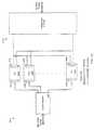
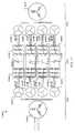
- FIGS. 1A-1Bshows schematic representations of exemplary power stages.
- FIG. 2shows a schematic representation of an exemplary power stage operating in a motoring mode to supply torque to a high-speed load.
- FIG. 3shows an exemplary diagram of a stator winding configuration in an electric machine.
- FIG. 4shows plots of exemplary voltage and current waveforms to illustrate operation in a motoring mode.
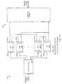
- FIG. 5shows a schematic representation of an exemplary power stage operating in a generating mode.
- FIG. 6shows plots of exemplary voltage and current waveforms to illustrate operation in a generating mode.
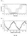
- FIGS. 7A-7Bshow plots of exemplary flux density in an air gap with line currents.
- FIG. 8shows plots of exemplary hub losses of different winding configurations.
- FIG. 9shows an exemplary network of a ship electrification system.
- FIG. 10shows plots of exemplary current waveform of different transformer-less electrical network topologies.
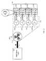
- FIG. 11shows an exemplary system having a generating and motoring topology.
- FIGS. 1A-1Bshow exemplary systems capable of converting mechanical energy to electrical energy (e.g., high power DC generation) or electrical energy to mechanical energy (e.g., high-speed motoring applications).
- a system 100includes a bank of a number (N) of switch matrices 105 a - 105 n , an electric machine 110 , and a voltage bus 115 .
- Each of the switch matrices 105 a - 105 nmay include an M-phase inverter for motoring, and/or an M-phase diode bridge for generation.
- Each of the switch matrices 105 a - 105 nalso includes a port 125 a - 125 n , respectively, each of the ports 125 a - 125 n including a pair of terminals for connecting to the voltage bus 115 .
- the machine 110includes a stator (not shown) that has N sets of windings.
- the electric machine 110can include a linear machine.
- the electric machine 110can include a rotating machine.
- the system 100may receive mechanical energy and output electrical energy when operating as a generator, and/or the system may receive electrical energy and output mechanical energy when operating as a motor.
- the N sets of windings in the machine 110are each phase-shifted from each other such that multiple stator current harmonics are substantially reduced during operation of the system 100 .
- the number of harmonics that are substantially reducedis a function of M, the number of phases in each set of windings, and N, the number of sets of windings.
- N# stator slots/(M. # of poles)
- Various embodimentsmay substantially reduce or cancel harmonics based on the number of sets of windings (e.g., the number of coils per pole).
- Various examplesmay have various numbers of coils per pole, winding layers, number of phases, stator slots, and the like.
- the phase shift, as a function of the number of phases (M) and the number of sets of windings (N),is pi/(M*N).
- Each of the N sets of windingsis connected to a corresponding one of the ports 120 a - 120 n .
- each of the sets of windingsis electrically isolated from the other windings.
- energyis separately delivered from the voltage bus 115 to each set of windings through the corresponding switch matrix 105 a - 105 n.
- energyis separately supplied from each set of windings through the corresponding switch matrix 105 a - 105 n to the voltage bus 115 .
- a voltage on the bus 115may be substantially unipolar.
- the voltage bus 115includes a positive rail (e.g., node) that connects to a positive terminal of each of the ports 125 a - 125 n , and a negative rail (e.g., node) that connects to a negative terminal of each of the ports 125 a - 125 n .
- the voltage bus 115receives a DC voltage from the switch matrices 105 a - 105 n .
- the switch matrices 105 a - 105 nmay invert the unipolar voltage on the voltage bus 115 .
- each of the switch matrices 105 a - 105 ncan invert the voltage using an M-phase inverter.
- the switch matrices 105 a - 105 nuse the inverted voltage to supply an AC waveform to drive each of the corresponding M-phase windings in the machine 110 .
- the switch matrices 105 a - 105 nmay be coordinated, for example, to provide controlled current, voltage, torque, speed, and/or position, for example.
- Switches in the switch matricesmay be operated, in some examples, at or near the fundamental electrical frequency supplied to the machine, or at a frequency substantially above the fundamental frequency.
- Techniques for controlling switches in the switch matricesmay include, but are not limited to, vector control, field-oriented control, phase control, peak current control, average current control, and/or pulse width modulation, or combinations of these or other techniques.
- switching frequencymay be based on factors, such as the output fundamental frequency, the harmonic levels required in the line current, load impedance, type of semiconductor device and drive topology used, for example.
- switching lossesmay be, for example, directly related to switching frequency.
- a maximum junction temperatures or safe operating areamay typically be specified in the manufacturer's data sheets.
- stator harmonic currentscan cause extra copper and iron losses in the stator core.
- stator harmonic currentmay also inject harmonic components into the air gap magnetic field that couples into the rotor, increasing losses in the rotor.
- the voltage ripple frequency on the voltage bus 115may be at (6Nf max ), where f max is the maximum output frequency of the electric machine. Typically, f max is in the kilohertz range for a high speed machine.
- the quality of the voltage bus 115is improved without using high frequency switching insulated gate bipolar transistors (IGBTs) or with substantially reduced filtering.
- the switch matrices 105 a - 105 ncan be connected in combinations of series and/or parallel to interface to the voltage bus 115 .
- a system 150includes the switch matrices 105 a - 105 n to be connected as a series combination of pairs of paralleled switch matrices.
- the switch matrix 105 ais connected in series with the switch matrix 105 b
- the switch matrix 105 n ⁇ 1is connected in series with the switch matrix 105 n .
- groups of the series connected switch matrices 105 a - 105 nare connected in parallel to interface with the voltage bus 115 .
- FIG. 2a schematic representation of an exemplary power stage 200 operating in a motoring mode to supply torque to a high-speed load 205 .
- the power stage 200can be used to power centrifugal compressor drives, integral hermetically sealed compressor drives, high speed blowers, and/or test beds for turbo components.
- the power stage 200includes four winding sets 215 a , 215 b , 215 c , 215 d . Each of the windings 215 a - d is configured to have a 15° phase difference from adjacent windings.
- the power stage 200can include 2-level drives feeding from a common DC node 230 .
- the electric machine 110may be an asynchronous or a synchronous machine (e.g., a permanent magnet synchronous machine).
- Nmay be selected based on the number of slots in the stator, number of rotor poles, and the amount of harmonic cancellation required.
- switching of inverter cellsmay be synchronized with the corresponding stator windings that are being fed.
- the fundamental output waveform of each inverter cellmay be phase shifted by ( ⁇ /3N) from an adjacent inverter cell. Because of the layout of the stator windings, some harmonics can be substantially reduced or cancelled.
- each inverter cellmay switch at an output fundamental frequency, or very close to it, and still substantially reduce the level of harmonics in the motor currents.
- Some embodimentsmay yield one or more advantages. For example, some systems may have reduced weight and volume of the machine because of the higher fundamental frequency when using standard AC converter topologies and cooling methods.
- output capabilities of the Ac drive components, such as the semiconductor devicesmay be increased by using low switching frequency while still maintaining low harmonic distortion in the line current.
- Optimized stator sizemay be obtained based on reduced requirements to handle switching harmonic losses that may be associated with higher frequency PWM inverter operation or with use of only one three-phase diode bridge. Harmonic coupling/heating into the rotor may be substantially reduced.
- Modular design on the power convertermay provide substantial fault tolerance in some embodiments, which may yield improved redundancy and higher availability.
- stator winding insulationmay be reduced, and/or insulation voltage level of the windings may be reduced by making different connections to the number of turns per coil and the number of coils per pole.
- Some embodimentsmay achieve generally high system efficiency and lower overall cost. Some embodiments may not need PWM control techniques, and/or may provide gear-less high-speed AC converter systems.
- FIG. 3shows an exemplary stator-winding configuration 300 of the electric machine 110 .
- the winding configuration 300can be used in a 48 slot/4 pole stator.
- the configuration 300includes 48 slots as represented by the vertical lines. Some slot numbers associated with their corresponding slots are presented as numbers overlay on the vertical lines.
- the stator configuration 300can split the N slots separately.
- the statorincludes a series of tooth structures that is separated by N slots. For example, N phases can be inserted in those N slots (A 1 , A 2 , A 3 . . . AN) of the stator configuration 300 .
- the stator configuration 300may then include N sets of three phase windings.
- each winding setcan include a single turn coil running in full pitch on the stator. In other examples, each winding set can include multi turn coil running in full pitch on the stator.
- the slot opening dimensionsmay be substantially equal.
- the tooth widthsmay be substantially equal.
- the stator configuration 300can include toothless stator designs (e.g., toroidal windings), such as when the winding is formed substantially in the stator core material.
- the configuration 300includes 4 slots per pole.
- the stator configuration 300can include equal number of slots in each of the poles.
- each pole of the statormay include 12 slots.
- the configuration 300splits the 12 slots of each pole separately.
- the windingscan be distributed such that each slot contains only one phase.
- phase A of winding 1 (A 1 )occupies slots 1 , 13 , 25 , 37
- phase A of winding 2 (A 2 )occupies slots 2 , 14 , 26 , 38 .
- the configuration 300can substantially mitigate harmonics in the stator iron and in an air gap between the stator and the rotor.
- the configuration 300can substantially reduce an impact of the 5th and 7th harmonic components in the phase currents on the generator from an iron loss and torque ripple standpoint.
- the first non-cancelled harmonic components in the air gap fluxcan be at (6N ⁇ 1).
- the first non-cancelled harmonic flux components in the machinemay be at 2*M*(N ⁇ 1).
- FIG. 4shows plots of exemplary waveforms 400 , 430 , 460 to illustrate operation in a motoring mode.
- substantial harmonic reductionmay result when the phase shifted harmonics from the adjacent three phase windings are summed up in the core of the stator.
- several of the harmonic componentshave been substantially cancelled out effectively, yielding an approximate total harmonic distortion (THD) of about 0.5%.
- TDDtotal harmonic distortion
- the synchronous d-axis and q-axis current waveformshave substantially low ripple content without PWM operation.
- the harmonic currentscan be substantially mitigated.
- An effect of this phase shiftis shown in FIG. 6 , where the harmonic components cancel out up to the (6N ⁇ 1) component.
- the first harmonic componentswould be the 23rd and the 25 th .
- the effective current waveform, which is injected into the statormay have a much lower THD value than typical rectifier three-phase bridge waveforms.
- the voltage ripple frequency on a main DC linkmay be at (6*N*f max ), where f max is the maximum output frequency of the generator, this would normally be in the several kilohertz range for a high-speed machine.
- the configuration 300can improve a transmission quality of the DC link.
- the prime movers 505may be separated from the stator 515 by a gap.
- the gapmay be filled with liquids or gasses, or a combination thereof.
- the gap between the rotor and statormay be partially or substantially filled with air, methane, nitrogen, hydrogen, oil, or a combination of these or other suitable materials in a liquid or gas phase.
- the power processing stage 520includes switch matrices 525 a , 525 b , 525 c , 525 d .
- Each of the switch matrices 525 a - dis connected to one of the winding sets of the stator 515 .
- the power processing stage 515includes two main DC links 530 , 535 . Both of the DC links 530 , 535 are coupled one of the output ports of the switch matrices 525 a - d . As shown, the switch matrices are connected in parallel to the DC links 530 , 535 .
- the switch matrices 525 a - dcan receive AC power from the stator 515 and output DC power to the DC links 530 , 535 .
- the frequency of the power signalscan be decreased from the power stage 515 to the power processing stage 520 .
- the DC links 530 , 535supply DC power to a DC distribution system 540 .
- the DC distribution system 540includes multiple DC-AC converters 545 a - 545 n and multiple DC-DC converters 550 a - 550 n .
- the DC-AC converters 545 a - 545 ncan convert DC power from the DC links 530 , 535 into AC power to support various AC devices.
- each of the DC-AC converters 545 a - 545 nis coupled to a corresponding AC filter 555 a - 555 n .
- the AC filters 555 a - 555 ncan supply 3-phase AC power output, such as AC power at 50 Hz or 60Hz with r.m.s. voltage of 480 V to 690 V.
- the DC-DC converters 545 a - 545 ncan include step-up converters or step-down converter. In some examples, the DC-DC converter 545 a - 545 n can supply power to DC applications using the DC power in the DC links 535 , 540 .
- the power processing stage 520can include a filter, a bridge rectifier, and/or other power conditioning components.
- the switch matrices 525 a - dcan be active switch matrices. Exemplary embodiments of a system for generating DC power or motoring using DC power are described in U.S. Provisional Patent Application 60/863,233 entitled “Energy Conversion System” by Ahmad, et al., filed on Oct. 27, 2006; and in U.S. Provisional Patent Application 60/864,882 entitled “Energy Conversion System” by Ahmad, et al., filed on Nov. 8, 2006.
- high-speed permanent magnet (PM) synchronous generatorscan be classified based on rotor construction, such as axial or radial gap PM generators.
- radial gap PM generatorscan be used in higher power ratings based on rotor dynamics.
- radial PM generatorscan be grouped into surface mount or embedded magnet generators. Surface mount PM generators are more cost effective and simpler to manufacture than embedded magnet based generators.
- surface mount PM generatorsuse a sleeve to provide the required containment and a solid rotor core, or hub, may provide increased radial stiffness. Different sleeve structures can be used for containing the magnet pieces at the high rotational speeds.
- some sleeves or membranesmay include either a high strength nickel based alloy and/or a composite carbon fiber material.
- the high-speed, sleeved (e.g., surface mount) PM generatorcan include a larger magnetic air-gap than the un-sleeved PM generator due to the sleeve thickness and the increased magnet thickness required to force an equivalent amount of flux through the larger magnetic gap.
- a larger magnetic gapcan provide better demagnetization protection under short-circuit conditions.
- the generatorcan gain the benefits of a lube-free system.
- magnetic bearingscan operate at higher speeds with less loss than certain types of mechanical bearings.
- a generating systemcan be constructed with a reduced system weight, higher operating efficiency, reduced maintenance costs, and a smaller envelope than a conventional solution in the same power rating.
- the system 100 and the system 500can, for example, include N sets of full pitch, three phase, space-shifted, split-phase windings for allowing connection to N passive three phase rectifiers, while keeping the machine losses to a minimal by achieving harmonic cancellation in the air gap of the machine.
- relatively thin, low loss silicon steelcan be used to contain losses under the high-frequency operation.
- FEAfinite element analysis
- rotor losses due to eddy-currentscan be predicted using a time-stepping, rotating-grid solver.
- a solutioncan be obtained with a two-dimensional analysis without considering axial segmentation of the magnets and the electrical isolation between adjacent magnets, or a magnet and the shaft.
- a finite element analysis toolmay be used to recreate the winding process of the rotor with carbon fibers in a polyetheretherketone (PEEK) matrix, including the effects of rotor temperature, as a time dependent variable, carbon fiber tension, and winding feed rate. Random generation of the rotor geometry node by node according to the manufacturing tolerances may provide a system model.
- PEEKpolyetheretherketone
- a FEA rotor dynamics software packagecan be used to analyze the free-free natural frequencies and mode shapes of the generator.
- the solution approach of the toolis to lump the mass and inertia of a defined area to create the nodes.
- the nodesare connected by mass-less beams.
- the magnetic bearingsare modeled as dynamic supports with variable stiffness and damping.
- the magnetic bearings used in this generatorconsist of two radial support bearings, one to either end of the shaft and a separate active thrust bearing at the coupled end to compensate for any axial loading.
- a coupling appropriate to the generator sizecan be chosen and can be modeled as a cantilevered weight.
- Loss breakdownmay be given by the electromagnetic modeling tool discussed above.
- a lumped parameter modelis used to model the generator geometry including rotor, stator, and cooling jacket to determine the correct mass flow required to maintain a max temperature of 150° C. at 40° C. ambient per coil insulation and carbon fiber.
- a scaled-down 100 kW back to back motor-generator systemcan be constructed.
- a stator of a generatorcan be configured with the proposed multiple space shifted split 3-phase winding structure.
- the statorscan have 24 slots and may use a 2 pole PM incanel based metal sleeved rotor. The electrical phase shift between adjacent slots is 15°, which may be equivalent to the simulated 48 slot, 4 pole case.
- the stator of the generatorconsists of 4 sets of 3-phase windings.
- Each winding setcan include, for example, 3 phase single-slot full-pitch windings occupying 6 slots.
- each winding setmay be rated at 400 V and 25 kW at 500 Hz.
- the statormay be configured with split phase winding structure and relatively long end turns relative to a fractional pitch stator. The difference may be, for example, less than half an inch.
- each three-phase winding setmay be feeding a three-phase diode ridge rectifier, each with a low inductive capacitive dc link.
- the outputs of the four rectifiersare coupled, either directly or in a network arrangement, together into one common DC bus and connected to a DC load bank.
- the statormay be equipped with several thermocouples for the temperature to be measured and recorded at different locations such as the slot back iron and tooth tip.
- FIGS. 7A-7Bshow exemplary plots of total synchronous frame flux density in the air gap and line currents.
- the plot 740shows a net magnetic flux density in the air gap including the effect of slot current time variation.
- FIG. 8shows plots 800 , 850 of exemplary hub losses of different winding configurations.
- the plot 800shows hub losses with different winding configurations.
- the plot 850shows peak-to-peak torque ripple with different winding configurations.
- FIG. 9shows an exemplary zonal DC distribution network 900 for an on-board application.
- the network 900includes three zones 905 , 910 , 915 .
- each of the zones 905 , 910 , 915can be a distinct area of a ship.
- the network 900includes two high-speed main generators 920 , 925 feeding two propulsion motors 930 , 935 on, for example, the port and the starboard sides of the ship. Also, the generators 920 , 925 can supply power to the ship service loads 940 a , 940 b , 940 c .
- the network 900includes a back up HS generator system 945 .
- the generators 920 , 925can be two individual 8 MW, 15,000 rpm, 48 slot stator and 4 pole rotor PM synchronous generators. Each of the generators 920 , 925 can be, for example coupled to two primary gas turbines.
- the statorcan be wound with space shifted, split phase, winding arrangement, as described with reference to FIG. 3 .
- each M phase winding setcan be feeding a passive M phase rectifier bridge. For example, the outputs of the bridges are connected in parallel and are feeding a common voltage bus 950 .
- the ship service loads 940 a - ccan be fed through step down transformers and sinusoidal filters from each of the independent zones 905 , 910 , 915 to provide isolation and limiting ground current interaction with the rest of the network 900 .
- the loads 940 a - ccan also be fed from a different zone in case of a fault.
- Each of the generators 920 , 925 , 945includes a rectifier bridge 955 , 960 , 965 , respectively.
- the rectifier bridges 955 , 960 , 965can include fast recovery diodes to handle the high fundamental frequency of the machine (500 Hz).
- the power rating of each of the rectifier bridges 955 , 960 , 965can be rated power divided by N.
- the rectifier bridges 955 , 960 , 965can be air cooled or liquid cooled and can be packaged into the generator housing.
- the generator packagecan include a compact medium voltage DC generator with integrated protection, switch gear, and DC interface bus bars.
- the network 900can include protective devices to isolate a faulty segment or zone with minimal degradation to the overall system.
- the network 900distributes DC power across the ship.
- the common voltage bus 950is ring shaped.
- the common voltage bus 950can be divided according to the zones 905 , 910 , 915 using switch module 970 a , 970 b , 970 c , 970 d , 970 e , 970 f .
- the switches 970 a - fcan electrically isolate each of the zones 905 , 910 , 915 such that the network 900 can be reconfigured by adding and/or removing isolated zone.
- the isolated zones 905 , 910 , 915can provide system redundancy and flexibility.
- the switches modules 970 a - fcan be a unidirectional or bidirectional semiconductor switch, solid state relay, or the like. Using the switch modules 970 a - f , the network 900 can disconnect one or more sets of windings in the generators 920 , 925 , 945 from the corresponding processing modules, and/or to disconnect one or more processing modules from the voltage bus 950 .
- the network 900can substantially maintain the associated windings in an off condition while the remaining sets of windings and modules continue to operate using actively controlled switch matrices, switching control signals.
- the systemin the event of winding failure in the Nth set of windings, the system can operate with N ⁇ 1 winding sets and the corresponding N ⁇ 1 processing modules.
- the electric machinemay be operated in an overloaded condition.
- one or more of the switch modules 970 a - fmay be opened to disconnect the failed module from the associated winding in the machine, and/or from the voltage bus.
- the network 900can reduce harmonic losses while having passive rectifier line current waveforms, with minimal harmonic coupling/heating into the rotor.
- the generator 920 , 925 and/or 945can substantially reduce or eliminate the need for high speed active rectifiers to reduce cost, size, and/or weight. For example, weight reduction can be higher than 90% when going from active to passive rectifiers. Additionally, by eliminating the AC-DC power electronic building block (PEBB) on the load converters (because DC distribution is used), an average of 30% to 40% further reduction in weight/size for the AC propulsion drives can be obtained.
- PEBBAC-DC power electronic building block
- one or more of the generators 920 , 925 , or 945can have a height of approximately 28′′, a length of approximately 53′′, a weight of approximately 1865 lbs, and a power density of approximately 2.37 kW/kg or 3770 kW/m 3 .
- passive rectifiershigh system reliability/survivability and lower running costs can be achieved.
- a higher system efficiencycan be obtained by using passive rectifiers.
- a roughly 2% higher efficiencycan be achieved using passive rectifiers as oppose to active rectifiers.
- system efficiencycan result in better overall fuel efficiency.
- the generators 920 , 925 , 945can have a wider prime mover speed range while maintaining controlled output at the load point converters.
- the network 900can be a fault tolerant system due to the redundancy (N rectifiers). Through over rating, the network 900 can lead to higher system availability (N+1), for example.
- N+1system availability
- the generators 920 , 925 , 945can have parallel operation using a transformer-less electrical network topology.
- the generators 920 , 925 , 945may optionally include inter-phase transformer (IPTs).
- FIG. 10shows exemplary plots 1000 , 1020 , 1040 , 1080 of DC current for different cases of back electromotive force (EMF) waveforms and with/without IPTs.
- the plot 1000shows a total load current for R load and individual bridge DC current for a system using IPTs.
- the plot 1020shows a total load current for R load and individual bridge DC current for a system without IPTs and sinusoidal back EMF.
- the plot 1040shows a total load current for R load and individual bridge DC current for a system without IPTs and actual back EMF.
- the plot 1080shows a line current for sinusoidal back EMF without IPTs, sinusoidal back EMF with IPTs, and actual back EMF without IPTs.
- the generator 920 , 925 , 945may not include isolation transformers since the neutral points of each winding set are isolated from each other.
- the network 900can include a simplified grounding scheme with minimal neutral point voltage shifting between the generators 920 , 925 , 945 . Using the simplified grounding scheme, the network 900 can reduce special control or filtering schemes.
- the network 900can be interfaced with a processor that can issue master-slave commands to the generators 920 , 925 , 945 to direct voltage control and load sharing on the voltage bus 950 .
- the voltage control and load sharing on the voltage bus 950can be controlled by having voltage droop control on each load point converter.
- the operating frequency range of the generators 920 , 925 , 945can be at 12 kHz.
- the quality of the DC linkcan be improved without the need for high frequency switching IGBTs or any filtering components.
- FIG. 11shows an exemplary system 1100 that is capable of generating and motoring.
- the system 1100includes a generating stage 1105 , a power processing stage 1110 , and a motoring stage 1115 .
- the generating stage 1105includes a generator 1120 to generate AC power.
- the generator 1120can include a stator with a series of tooth structures separated by slots.
- the generating stage 1105includes four sets of windings 1125 a , 1125 b , 1125 c , 1125 d .
- the windings 1125 a - dcan be arranged substantially symmetrically in the slots of the stator.
- the windings 1125 a - dcan include M phases.
- each of the windings 1125 a - dincludes three phases.
- Mcan be two, three, four, eight, or other numbers greater or equal to two.
- each of the windings 1125 a - dmay have 15° phase difference from adjacent windings.
- the arrangement in the windings 1125 a - dcan substantially reduce a harmonic content of a magnetic flux within a first frequency range during operation.
- the power processing stage 1110includes generator side rectifier bridges 1130 a , 1130 b , 1130 c , 1130 d , capacitors 1135 a , 1135 b , 1135 c , 1135 d , and motor side inverters 1140 a , 1140 b , 1140 c , 1140 d .
- each of the generator side rectifier bridges 1130 a - dis coupled to a corresponding set of windings 1125 a - d to receive AC power from the generator stage 1105 .
- Each of the generator side rectifier bridges 1130 a - dincludes three input ports.
- the rectifier bridges 1130 a - dcan include M input ports in which M is the number of phases in each of the corresponding windings.
- the rectifier bridges 1130 a - dcan convert the received AC power into a substantially DC power for output.
- Each of the rectifier bridges 1130 a - dincludes two output ports. Through the output ports, each of the rectifier bridges 1130 a - d may be connected to the corresponding capacitors 1135 a - d.
- Each of the capacitors 1135 a - dis coupled to the corresponding motor side inverters 1140 a - d .
- the motor side inverters 1140 a - dcan receive DC power from the voltage bus and output AC power to the motoring stage 1115 .
- the capacitors 1135 a - dmay include filter elements for filtering undesired frequency components in the power signal. In other embodiments, other filter elements (e.g., common mode chokes) can also be used.
- the generator side rectifier bridges 1130 a - d and the motor side inverters 1140 a - dare connected in parallel.
- other combinations of series and parallel connectioncan be used to connect the generator side rectifier bridges 1130 a - d and the motor side inverters 1140 a - d .
- the rectifier bridges 1130 a - d and the inverters 1140 a - dcan be connected to a common voltage bus in groups of two, in which each group is connected in parallel as described with reference to FIG. 1B .
- the rectifier bridges 1130 a - bcan be connected in series and the rectifier bridges 1130 c - d can be connected in series.
- the outputs of the group of the rectifier bridges 1130 a - bcan be connected to the capacitors 1135 a - b .
- the outputs of the group of the rectifier bridges 1130 c - dcan be connected to the capacitors 1135 c - d .
- two or more of the recitifier bridges 1130 a - d and/or inverters 1140 a - dcan share a common voltage bus, for example.
- the motoring stage 1115receives AC power from the inverters 140 a - d .
- the motoring stage 1115includes four sets of windings 1150 a , 1150 b , 1150 c , 1150 d .
- Each of the windings 1150 a - dcan receive AC power from the corresponding inverters 1140 a - d .
- the motoring stage 1115includes a motor 1155 .
- the motor 1155can receive electrical power from the windings 1150 a - d and output mechanical power.
- high speed, high power applicationscan have significant requirements on the power electronics, which may significantly increase the overall system cost.
- drive costcan be significantly higher than the machine cost.
- an electric distribution platform designer for a system such as the system 1100may focus on drive optimization and matching machine parameters to drive capabilities.
- an arrangement of the system 1100can match N number of multiple modules feeding single or N sets of multiple phase (e.g., 5 phase) stator windings. In some examples, different stator winding arrangements can be selected based on current and voltage requirements.
- the system 1100can include stand alone high speed machine and drive packages. For example, the generator 1120 or the motor 1155 can be replaced independently without modifying the power processing stage 1110 . In some examples, the system 1110 can be a cost effective high speed high power solution.
- drive solutionscan be applied to the high speed, high power solutions to achieve higher system power ratings using a modular approach.
- power electronicsmay operate with a higher THD values in the machine phase currents (e.g., by permitting lower switching frequency).
- a system for high speed generating applicationscan include a high speed alternator.
- these applicationscan include gas turbine driven power generation, turbo expanders for exhaust recovery applications for large diesel shipboard engines, and turbo expanders for waste heat and waste steam recovery applications.
- an exemplary on-board generation systemcan include a high speed prime mover, such as a gas or steam turbine, which is directly coupled to a high speed AC Permanent Magnet (PM) Generator.
- the stator of the generatorincludes a set (N) of three phase windings. Each set of a three phase winding may feed a three-phase six-pulse diode bridge.
- the stator of the generatorincludes (N) sets of (M) phase windings. Each set of M phase windings may feed an M-phase, 2*M-pulse diode bridge.
- the outputs of all N diode bridgesmay be connected in parallel, for example, and feed a main DC link (e.g., voltage bus).
- the DC linkmay feed one or more DC/AC and/or DC-DC converters that may generate the required output voltage as a stand alone supply or as part of a distributed generation system.
- Some embodimentsmay have one or more advantages in various applications, such as those in which size and/or weight play a significant role in selecting the proper generation system (e.g., ship board electrical generation systems and heat recovery systems).
- proper generation systeme.g., ship board electrical generation systems and heat recovery systems.
- some embodimentsmay be adapted by modifying teeth and/or slot widths in the stator. Varying such widths may, for example, provide additional phase shift (e.g., ⁇ ) between winding coils that may improve stator harmonic cancellation.
- Overlap (e.g., shading) insulation, wire layout (e.g., as it relates to resistance, inductance, interwinding capacitance, and the like)may be adjusted to take advantage or to improve stator harmonic current cancellation, including, for example, in embodiments with toothless stator configurations, for example.
- Nmay include N sets of windings, each set of the windings having M phases.
- Ncan be greater than or equal to two (e.g., 2, 3, 4, 5, 6, 7, 8, 10, 12, 15, 18, 20, 21, 24, . . . 50 or more).
- Nmay be equal to the number of coils per pole.
- Nmay be less than (e.g., half) the number of coils per pole.
- Mcan be greater than three (e.g., 3, 4, 5, 6, 7, 8, 10, 12, 15, 18, 20, 21, 24, . . . 50 or more).
- Mcan be two or one.
- the windingscan be full-pitch.
- one or more windingsmay have substantially fractional pitch.
- the electric machinecan include an integral number of slots-per-pole-per-phase or a non-integral number of slots-per-pole-per-phase.
- Some embodimentsmay include power-electronic switches that are actively controlled (e.g. insulated gate bipolar transistors, IGBTs). Other embodiments may include passive power electronic switches (e.g., diodes).
- switch matricese.g., the switch matrices 105 a - 105 n
- switch matricescan be connected in series.
- outputs of one or more of the switch matricescan feed distinct loads.
- a single electric machine with N winding setsmay be connected to up to N (e.g., N, N ⁇ 1, N ⁇ 2, etc . . .
- switch matricese.g., passive or actively controlled
- switch matricesfor operation in a generating mode
- up to Ne.g., N, N ⁇ 1, N ⁇ 2, etc . . .
- switch matricese.g., actively controlled
- the number of switch matrices for operation in the generating modeneed not be the same as the number of switch matrices for operation in the motoring mode.
- one or more of actively controlled switch matricesmay serve a single electrical machine in both a motoring mode and in a generating mode.
- a generation or motoring systemcan include passive filter elements between the machine 110 and the switch matrices 105 a - 105 n .
- the system 100can include passive filter elements after the switch matrices 105 a - 105 n .
- the system 150can include active filter elements between the machine 110 and the switch matrices 105 a - 105 n.
- the system 100can also include active filter elements after the switch matrices 105 a - 105 n .
- the filter elementscan have a common connection point.
- the passive filter elementscan include an IPT.
- a stator windingcan have a double layer winding or a single layer winding. In some embodiments, a portion of the stator coils can be terminated on one end of the stator and the remaining coils are terminated on the opposite end of the stator.
- an electric power generation system(e.g., the system 500 ) can include a linear electric machine with a stator having multiple (N) poly-phase (M-phase) winding sets and a power-electronic switch matrix for each poly-phase winding set.
- an electric power generation system(e.g., the system 500 ) can include a rotating electric machine with a stator having multiple (N) poly-phase (M-phase) winding sets, a multi-pulse transformer, and a power-electronic switch-matrix for each poly-phase winding set.
- the multi-pulse transformercan be used in motoring applications.
- an electric power generation system(e.g., the system 500 ) can include a linear electric machine with a stator having multiple (N) poly-phase (M-phase) winding sets, a multi-pulse transformer, and a power-electronic switch matrix for each poly-phase winding set.
- air gap flux harmonic cancellationmay be applied to a variety of types of machine designs, including synchronous, induction, wound rotor, reluctance, permanent magnet, for example.
- Some embodimentsmay substantially control losses associated with stator harmonic currents in high-speed machines by switching the drive semiconductor devices at substantially low switching frequencies (e.g., fundamental frequency in the case of diode bridges). Switching losses in the devices may call for increased thermal management to address motor and power electronics temperatures. This may, for example, reduce system temperatures, thus allowing for increased lifetime or simply allowing for more power capacity out of the system, which may reduce or eliminate the need for cooling mechanisms to remove heat from the drive system components, such as the semiconductors, bus bars, and/or cables, for example. As applied to high power and medium-to-high voltage applications, reduced switching frequency generally involves reduced insulation ratings to withstand the repetitive switching of the AC drive devices. Fundamental (or near fundamental) switching frequencies may also reduce conducted and/or radiated EMI (Electro Magnetic Interference) emissions that may adversely affect neighboring systems. These and other issues can simplify drive integration and packaging.
- fundamental frequenciese.g., fundamental frequency in the case of diode bridges.
- a voltage on the bus 115may be controlled by a speed governor on the prime mover.
- voltage bus circuitrymay include a number of various loads and/or sources.
- the voltage bus 115may provide a DC transmission to supply distributed loads, for example, on board a ship, aircraft, or other environment that uses a DC utility grid (e.g., transformer-less systems).
- the loadsmay include, but are not limited to, switch-mode and/or linear loads, DC-to-AC loads (e.g., propulsion or traction systems), DC motors, lighting, heating, or combinations of these or other loads.
- the current waveformscan be distorted by the time-harmonic harmonic components. Namely the fifth, seventh, and higher order multiples of the fundamental frequency.
- the current waveform distortioncan produce additional losses in the machine, which can limit the power and/or speed capability of the system.
- switching devicesIn a typical active rectifier, switching devices generally switch at higher frequency as the machine rotates faster. However, as the devices switch faster, their switching losses can increase, which can lead to significant heat dissipation in the switching devices. Furthermore, switching losses are proportional to the operating power of the device. Accordingly, switching losses in the drive may determine speed and/or power capability for the overall system.
- Some generation applicationsuse a multiple three-phase-winding system, phase shifted from each other, typically two three-phase-winding sets phase shifted by 30 degrees electrical, to achieve harmonic cancellation in the air gap flux distribution
- some embodimentsinclude a system for use with a high-speed prime-mover, an electromechanical unit (e.g., high-speed permanent-magnet machines) and a high frequency (e.g., substantially above 120 Hz fundamental frequency) multi-pulse (6N) transformer with one three-phase primary winding and multiple three-phase secondary windings feeding N three-phase passive-rectifier bridges.
- an electromechanical unite.g., high-speed permanent-magnet machines
- 6Nmulti-pulse
- 6Nmulti-pulse
- This embodimentmay achieve low order harmonic cancellation in the air-gap flux of the machine while using passive rectifiers without the need for active rectification systems or any modifications to the machine stator windings.
- coolingmay include axial flow of a thermal transfer fluid (e.g., liquid, gas, or a combination thereof) in the gap between the rotor and the stator, and/or end turn cooling using a flow of a thermal transfer fluid.
- a substantial portion of the fluid in the gapmay include methane, hydrogen, nitrogen, natural gas, oil, or a combination of these and/or other fluids, which may or may not be flammable.
- a cooling systemmay include both forced axial air flow through the air gap and an independent air curtain to cool end turns at either or both ends of the rotor. Examples of such a system are described in a copending provisional patent application U.S. Provisional Patent Application 60/895,025 entitled “High-Speed, Sleeved Rotor for Permanent Magnet Electric Machines” by Saban, et al., filed on Mar. 15, 2007, with common inventors, the contents of which are incorporated herein by reference. Some examples may include protection for sleeving the rotor and/or stator components to isolate them from the medium in the gap.
- Some embodimentsinclude an exemplary topology for configuring the machine stator as a filter by controlling the inductances, air-gap, and winding configuration to allow the stator to act as a filter for harmonics present in the phase currents. This alleviates the use of external filters to the machine before connecting to passive rectifier bridges.
- the topologymay include a high speed AC machine stator winding configuration that is based on using a single coil per pole per phase. Such a configuration may provide advantages in economically achieving N>2 without adding significant complexity and cost into the machine, while extending flexibility in current/voltage design trade-offs during the machine electromagnetic design.
- Embodiments having N sets of M phase windings in a generatormay provide fault tolerance and continuous operation in the case of either a failure on the converter side or the machine side or both. De-rating will depend on the sizing of the individual converter block and the machine winding set.
- High speed machine attributes in terms of reduced size, weight and foot printmay be matched on the power electronics and auxiliary equipment side.
- the system topologyprovides for system isolation and redundancy substantially without the need for isolation transformers, current sharing reactors or Inter Phase Transformers (IPTs), although such elements may be incorporated to serve a flexible range of well known functions.
- IPTsInter Phase Transformers
Landscapes
- Engineering & Computer Science (AREA)
- Power Engineering (AREA)
- Microelectronics & Electronic Packaging (AREA)
- Windings For Motors And Generators (AREA)
- Supply And Distribution Of Alternating Current (AREA)
- Synchronous Machinery (AREA)
- Paper (AREA)
- Medicines That Contain Protein Lipid Enzymes And Other Medicines (AREA)
- Control Of Ac Motors In General (AREA)
- Permanent Magnet Type Synchronous Machine (AREA)
- Optical Integrated Circuits (AREA)
Abstract
Description
N=# stator slots/(M. # of poles)
Various embodiments may substantially reduce or cancel harmonics based on the number of sets of windings (e.g., the number of coils per pole). In one embodiment, a 48 slot stator may use, by way of example and not limitation, N=2, or N=4. Various examples may have various numbers of coils per pole, winding layers, number of phases, stator slots, and the like. The first harmonic components that are not substantially reduced or canceled, as a function of the number of sets of windings (N), may be (6N+/−1) for a three-phase (M=3) system. The phase shift, as a function of the number of phases (M) and the number of sets of windings (N), is pi/(M*N).
Claims (31)
Priority Applications (1)
| Application Number | Priority Date | Filing Date | Title |
|---|---|---|---|
| US12/749,226US7960948B2 (en) | 2006-10-27 | 2010-03-29 | Electromechanical energy conversion systems |
Applications Claiming Priority (5)
| Application Number | Priority Date | Filing Date | Title |
|---|---|---|---|
| US86323306P | 2006-10-27 | 2006-10-27 | |
| US86488206P | 2006-11-08 | 2006-11-08 | |
| US89502507P | 2007-03-15 | 2007-03-15 | |
| US11/751,450US7710081B2 (en) | 2006-10-27 | 2007-05-21 | Electromechanical energy conversion systems |
| US12/749,226US7960948B2 (en) | 2006-10-27 | 2010-03-29 | Electromechanical energy conversion systems |
Related Parent Applications (1)
| Application Number | Title | Priority Date | Filing Date |
|---|---|---|---|
| US11/751,450ContinuationUS7710081B2 (en) | 2006-10-27 | 2007-05-21 | Electromechanical energy conversion systems |
Publications (2)
| Publication Number | Publication Date |
|---|---|
| US20100244599A1 US20100244599A1 (en) | 2010-09-30 |
| US7960948B2true US7960948B2 (en) | 2011-06-14 |
Family
ID=39322381
Family Applications (2)
| Application Number | Title | Priority Date | Filing Date |
|---|---|---|---|
| US11/751,450Active2028-07-22US7710081B2 (en) | 2006-10-27 | 2007-05-21 | Electromechanical energy conversion systems |
| US12/749,226ActiveUS7960948B2 (en) | 2006-10-27 | 2010-03-29 | Electromechanical energy conversion systems |
Family Applications Before (1)
| Application Number | Title | Priority Date | Filing Date |
|---|---|---|---|
| US11/751,450Active2028-07-22US7710081B2 (en) | 2006-10-27 | 2007-05-21 | Electromechanical energy conversion systems |
Country Status (12)
| Country | Link |
|---|---|
| US (2) | US7710081B2 (en) |
| EP (2) | EP2197088A3 (en) |
| JP (1) | JP2010508802A (en) |
| KR (1) | KR20090074265A (en) |
| CN (1) | CN101584102B (en) |
| AT (1) | ATE462216T1 (en) |
| AU (1) | AU2007317638B2 (en) |
| CA (1) | CA2664864C (en) |
| DE (1) | DE602007005507D1 (en) |
| DK (1) | DK2082471T3 (en) |
| MX (1) | MX2009004497A (en) |
| WO (1) | WO2008057789A2 (en) |
Cited By (21)
| Publication number | Priority date | Publication date | Assignee | Title |
|---|---|---|---|---|
| US20070293104A1 (en)* | 2003-09-02 | 2007-12-20 | Normann Sandoy | Propulsion System for Ships |
| US20090243774A1 (en)* | 2002-02-15 | 2009-10-01 | Hitachi Metals, Ltd. | Magnetic field generator manufacturing method |
| US20120146563A1 (en)* | 2009-08-19 | 2012-06-14 | Siemens Aktiengesellschaft | Arrangement having an electric machine and method for operating an electric machine |
| US20130062889A1 (en)* | 2010-03-23 | 2013-03-14 | Adaptive Generators As | Variable electrical generator |
| US20140209586A1 (en)* | 2013-01-29 | 2014-07-31 | Shenzhen Jasic Technology Development Co., Ltd | Portable igbt arc welding machine |
| US20160301348A1 (en)* | 2013-03-15 | 2016-10-13 | Powerest LLC | Dynamically Reconfigurable Motors and Generators and Systems |
| US20170359009A1 (en)* | 2016-06-08 | 2017-12-14 | Hamilton Sundstrand Corporation | High voltage dc power generating system including selectively removable neutral node |
| US10483886B2 (en) | 2017-09-14 | 2019-11-19 | Hamilton Sundstrand Corportion | Modular electric power generating system with multistage axial flux generator |
| US20190359307A1 (en)* | 2018-05-24 | 2019-11-28 | Caterpillar Inc. | Power distribution system for a marine vessel |
| US10547259B1 (en)* | 2018-08-03 | 2020-01-28 | Hamilton Sundstrand Corporation | Electric generating system with an interleaved DC-DC converter |
| US20200059179A1 (en)* | 2017-04-27 | 2020-02-20 | Anax Holdings, Llc | System and method for electricity production from pressure reduction of natural gas |
| US10651770B2 (en) | 2018-08-29 | 2020-05-12 | Hamilton Sundstrand Corporation | Direct current voltage regulation of a six-phase permanent magnet generator |
| US20200194976A1 (en)* | 2016-12-21 | 2020-06-18 | Single Buoy Moorings Inc. | Power generation and distribution arrangement and floating unit comprising such an arrangement |
| US10778127B2 (en)* | 2018-09-10 | 2020-09-15 | Hamilton Sundstrand Corporation | Direct current voltage regulation of permanent magnet generator |
| US10797612B2 (en) | 2017-08-01 | 2020-10-06 | Ge Aviation Systems Llc | Power distribution network |
| US10855216B2 (en) | 2018-09-10 | 2020-12-01 | Hamilton Sundstrand Corporation | Voltage regulation of multi-phase permanent magnet generator |
| US10870474B2 (en) | 2013-08-06 | 2020-12-22 | Kongsberg Maritime CM AS | Dynamic positioning vessel with a plurality of redundancy zones |
| US11196310B2 (en) | 2018-07-30 | 2021-12-07 | Zunum Aero, Inc. | Permanent magnet assemblies for a cylinder of an electrical machine |
| US11296569B2 (en) | 2018-07-12 | 2022-04-05 | Zunum Aero, Inc. | Multi-filar coil winding for electric machine |
| US11387764B2 (en) | 2018-07-12 | 2022-07-12 | Zunum Aero, Inc. | Multi-inverter system for electric machine |
| US11710991B2 (en) | 2020-08-25 | 2023-07-25 | General Electric Company | High voltage electric machine equipped with galvanic separators for cascaded voltage stator modularization |
Families Citing this family (143)
| Publication number | Priority date | Publication date | Assignee | Title |
|---|---|---|---|---|
| US8395288B2 (en)* | 2005-09-21 | 2013-03-12 | Calnetix Technologies, L.L.C. | Electric machine with centrifugal impeller |
| JP4736871B2 (en)* | 2006-03-10 | 2011-07-27 | 株式会社日立製作所 | Power converter for secondary excitation power generation system |
| US7977842B2 (en)* | 2006-10-05 | 2011-07-12 | Lin Panchien | Adaptive winding system and control method for electric machines |
| US7710081B2 (en) | 2006-10-27 | 2010-05-04 | Direct Drive Systems, Inc. | Electromechanical energy conversion systems |
| JP5642393B2 (en)* | 2007-03-15 | 2014-12-17 | ダイレクト、ドライヴ、システィムズ、インク | Electromechanical cooling |
| US7468561B2 (en)* | 2007-03-27 | 2008-12-23 | General Electric Company | Integrated electrical power extraction for aircraft engines |
| US8839622B2 (en)* | 2007-04-16 | 2014-09-23 | General Electric Company | Fluid flow in a fluid expansion system |
| US7638892B2 (en)* | 2007-04-16 | 2009-12-29 | Calnetix, Inc. | Generating energy from fluid expansion |
| US7841306B2 (en)* | 2007-04-16 | 2010-11-30 | Calnetix Power Solutions, Inc. | Recovering heat energy |
| US8049358B2 (en)* | 2007-10-15 | 2011-11-01 | Converteam Technology Ltd | Marine power distribution and propulsion systems |
| FI121407B (en)* | 2007-12-27 | 2010-10-29 | Waertsilae Finland Oy | Local power transmission network load distribution system fault handling arrangement |
| GB2456179B (en)* | 2008-01-07 | 2012-02-15 | Converteam Technology Ltd | Marine power distribution and propulsion systems |
| US8310123B2 (en) | 2008-07-28 | 2012-11-13 | Direct Drive Systems, Inc. | Wrapped rotor sleeve for an electric machine |
| US20110241630A1 (en) | 2008-09-03 | 2011-10-06 | Exro Technologies Inc. | Power conversion system for a multi-stage generator |
| EP2161819A1 (en)* | 2008-09-08 | 2010-03-10 | Converteam Technology Ltd | Assemblies for electrical machines |
| WO2010083054A1 (en) | 2009-01-16 | 2010-07-22 | Jore Matthew B | Segmented stator for an axial field device |
| EP2239435A1 (en)* | 2009-04-06 | 2010-10-13 | Alstom Technology Ltd | Electrical generator and method for operating a cooling circuit of an electrical generator |
| DE102009017157B4 (en)* | 2009-04-15 | 2011-02-17 | Siemens Aktiengesellschaft | Method for supplying an electrical ship's electrical system with external energy, ship with such a foreign energy supply and retrofit method for this |
| US8050069B2 (en)* | 2009-05-29 | 2011-11-01 | General Electric Company | Method and apparatus for electrical bus centering |
| US9300131B2 (en)* | 2009-06-01 | 2016-03-29 | Abb Research Ltd. | Internal electrification scheme for power generation plants |
| US7863766B2 (en)* | 2009-06-30 | 2011-01-04 | Teco-Westinghouse Motor Company | Power converter for use with wind generator |
| EP2474092B1 (en) | 2009-09-03 | 2020-04-29 | DPM Technologies Inc. | Variable coil configuration system, apparatus and method |
| CN102025248B (en)* | 2009-09-18 | 2014-03-12 | 德昌电机(深圳)有限公司 | Motor used for power system of electric vehicle |
| US8330291B2 (en)* | 2009-10-02 | 2012-12-11 | General Electric Company | Power generation apparatus |
| EP2312744B1 (en)* | 2009-10-13 | 2012-07-11 | Converteam Technology Ltd | Power distribution systems |
| US8497664B2 (en)* | 2009-11-19 | 2013-07-30 | GM Global Technology Operations LLC | High efficiency multi-phase generator |
| US8294320B2 (en)* | 2010-02-17 | 2012-10-23 | GM Global Technology Operations LLC | Interior permanent magnet machine |
| JP5234050B2 (en)* | 2010-04-27 | 2013-07-10 | 株式会社デンソー | Vehicle power supply |
| US8739538B2 (en) | 2010-05-28 | 2014-06-03 | General Electric Company | Generating energy from fluid expansion |
| US9154024B2 (en) | 2010-06-02 | 2015-10-06 | Boulder Wind Power, Inc. | Systems and methods for improved direct drive generators |
| AT510118A1 (en)* | 2010-07-01 | 2012-01-15 | Hehenberger Gerald Dipl Ing | SPEED VARIABLE GENERATOR FOR A WIND POWER PLANT AND METHOD FOR OPERATING THIS GENERATOR |
| WO2012016062A2 (en)* | 2010-07-28 | 2012-02-02 | Direct Drive Systems, Inc. | Multi-leveled phase shifted electric machine system |
| US20130181688A1 (en)* | 2010-10-06 | 2013-07-18 | Raven Energy Alternatives, Llc | System and method for variable speed generation of controlled high-voltage dc power |
| FR2967529B1 (en) | 2010-11-12 | 2013-09-13 | Erneo | DENTAL ROTATING ELECTRIC MACHINE WITH REGULATED PHASES |
| US8629644B2 (en)* | 2010-11-16 | 2014-01-14 | Hamilton Sundstrand Corporation | Fault tolerant DC power systems |
| US9764727B1 (en) | 2010-11-23 | 2017-09-19 | Ge Energy Power Conversion Technology Limited | Electric drive-train for ships |
| EP2477325B1 (en)* | 2011-01-18 | 2019-04-24 | Vestas Wind Systems A/S | Method for operating an electromechanical generator |
| CN102097894B (en)* | 2011-01-30 | 2012-07-25 | 陈维加 | Generation method for AC generator and generator |
| US20120194030A1 (en)* | 2011-01-31 | 2012-08-02 | Kollmorgen Corporation | Force Balanced Multivoltage Winding Configuration |
| US8400038B2 (en) | 2011-04-13 | 2013-03-19 | Boulder Wind Power, Inc. | Flux focusing arrangement for permanent magnets, methods of fabricating such arrangements, and machines including such arrangements |
| GB201113694D0 (en)* | 2011-08-09 | 2011-09-21 | Univ Southampton | Turbine generator |
| CN102510260B (en)* | 2011-11-17 | 2014-03-12 | 华中科技大学 | Induction machine vector control method taking account of iron loss |
| CN103187860A (en)* | 2011-12-30 | 2013-07-03 | 哈米尔顿森德斯特兰德公司 | Fault-tolerant direct current (DC) power system |
| US8984884B2 (en) | 2012-01-04 | 2015-03-24 | General Electric Company | Waste heat recovery systems |
| US9024460B2 (en) | 2012-01-04 | 2015-05-05 | General Electric Company | Waste heat recovery system generator encapsulation |
| US9018778B2 (en) | 2012-01-04 | 2015-04-28 | General Electric Company | Waste heat recovery system generator varnishing |
| US20130193813A1 (en)* | 2012-01-31 | 2013-08-01 | Hamilton Sundstrand Corporation | Integrated high-voltage direct current electric power generating system |
| ES2552857T3 (en) | 2012-02-29 | 2015-12-02 | Abb Technology Ltd | A DC power system with system protection capabilities |
| US9531289B2 (en) | 2012-04-27 | 2016-12-27 | Raytheon Company | Electro-mechanical kinetic energy storage device and method of operation |
| DE102012207809A1 (en)* | 2012-05-10 | 2013-11-14 | Robert Bosch Gmbh | Range extender, drive and motor vehicle |
| EP2685616B1 (en)* | 2012-07-10 | 2015-06-17 | Siemens Aktiengesellschaft | Stator arrangement and electrical generator |
| CN103580494B (en)* | 2012-07-19 | 2016-04-20 | 台达电子工业股份有限公司 | Converter system |
| US8339019B1 (en) | 2012-07-30 | 2012-12-25 | Boulder Wind Power, Inc. | Structure for an electromagnetic machine having compression and tension members |
| EP2704297B1 (en)* | 2012-08-28 | 2020-02-19 | GE Energy Power Conversion Technology Ltd | DC electrical machines |
| EP2720340B1 (en)* | 2012-10-15 | 2015-01-21 | Airbus Operations GmbH | Electric power supply system for an aircraft, aircraft and airport power supply system |
| EP2728713A1 (en)* | 2012-10-31 | 2014-05-07 | Openhydro IP Limited | An electrical machine |
| US20140156099A1 (en) | 2012-12-05 | 2014-06-05 | Cummins Power Generation, Inc. | Generator power systems with active and passive rectifiers |
| JP6131274B2 (en)* | 2012-12-21 | 2017-05-17 | 川崎重工業株式会社 | Parallel operation control method and control system between different types of power generators |
| DE102013200019B4 (en)* | 2013-01-02 | 2021-09-30 | Bombardier Transportation Gmbh | Supplying electric traction motors of a rail vehicle with electrical energy using a plurality of internal combustion engines |
| US20140265672A1 (en)* | 2013-03-13 | 2014-09-18 | Remy Technologies, Llc | Phase lead insulator |
| US8736133B1 (en) | 2013-03-14 | 2014-05-27 | Boulder Wind Power, Inc. | Methods and apparatus for overlapping windings |
| US9240748B2 (en)* | 2013-03-15 | 2016-01-19 | Hengchun Mao | Dynamically reconfigurable motor and generator systems |
| US9475381B2 (en) | 2013-05-15 | 2016-10-25 | Ford Global Technologies, Llc | System and method for reducing power train air resistance |
| GB201313684D0 (en)* | 2013-07-31 | 2013-09-11 | Rolls Royce Plc | A stator winding arrangement for an electrical machine |
| US9571022B2 (en)* | 2013-08-30 | 2017-02-14 | Abb Schweiz Ag | Electrical generator with integrated hybrid rectification system comprising active and passive rectifiers connected in series |
| US9385645B2 (en)* | 2013-08-30 | 2016-07-05 | Abb Technology Ag | Methods and systems for electrical DC generation |
| WO2015031878A1 (en)* | 2013-08-31 | 2015-03-05 | Infinirel Corporation | Control system for energy conversion in an electrical machine |
| US9148022B2 (en)* | 2013-09-17 | 2015-09-29 | King Fahd University Of Petroleum And Minerals | Wind turbine permanent magnet synchronous generator (WT-PMSG) system |
| US9294016B2 (en)* | 2013-12-19 | 2016-03-22 | Google Inc. | Control methods and systems for motors and generators operating in a stacked configuration |
| US9680376B2 (en)* | 2014-02-28 | 2017-06-13 | Cree, Inc. | Power conversion electronics having conversion and inverter circuitry |
| US9461547B2 (en) | 2014-03-07 | 2016-10-04 | Cree, Inc. | Converter circuitry |
| US9531247B2 (en)* | 2014-04-04 | 2016-12-27 | Raytheon Company | Inertial energy storage system and hydro-fluoro-ether power transformer scheme for radar power systems and large PFN charging |
| US9899886B2 (en) | 2014-04-29 | 2018-02-20 | Boulder Wind Power, Inc. | Devices and methods for magnetic flux return optimization in electromagnetic machines |
| US10177620B2 (en) | 2014-05-05 | 2019-01-08 | Boulder Wind Power, Inc. | Methods and apparatus for segmenting a machine |
| US20150349598A1 (en)* | 2014-05-28 | 2015-12-03 | Hamilton Sundstrand Corporation | Multiplex winding synchronous generator |
| US9698589B1 (en)* | 2014-06-09 | 2017-07-04 | Google Inc. | DC power distribution architectures |
| US9911532B2 (en) | 2014-08-25 | 2018-03-06 | Raytheon Company | Forced convection liquid cooling of fluid-filled high density pulsed power capacitor with native fluid |
| US9742331B2 (en)* | 2014-09-17 | 2017-08-22 | Abb Schweiz Ag | Doubly-fed, variable-speed, dual-voltage AC generation and distribution systems |
| CN107112898B (en) | 2014-11-18 | 2019-06-21 | 通用电气全球采购有限责任公司 | Busbars and power electronics and method of making terminal connectors |
| US20160175968A1 (en)* | 2014-12-19 | 2016-06-23 | Illinois Tool Works Inc. | Method and apparatus for providing welding and auxiliary power |
| US9837996B2 (en) | 2015-01-07 | 2017-12-05 | Raytheon Company | Method and apparatus for control of pulsed power in hybrid energy storage module |
| US10008854B2 (en) | 2015-02-19 | 2018-06-26 | Enphase Energy, Inc. | Method and apparatus for time-domain droop control with integrated phasor current control |
| US9665672B2 (en)* | 2015-04-27 | 2017-05-30 | Christian Dufour | Method and system for reducing power losses and state-overshoots in simulators for switched power electronic circuit |
| AU2016202657B2 (en)* | 2015-04-28 | 2021-02-04 | Joy Global Surface Mining Inc | Multi-pulse transformer for use with an industrial machine |
| US9667232B2 (en) | 2015-05-13 | 2017-05-30 | Raytheon Company | System and method for parallel configuration of hybrid energy storage module |
| DE102015213648A1 (en)* | 2015-07-20 | 2017-01-26 | Lenze Automation Gmbh | Method of operating a frequency converter and frequency converter |
| DE102015213580A1 (en)* | 2015-07-20 | 2017-01-26 | Siemens Aktiengesellschaft | Propeller drive and vehicle, in particular aircraft |
| EP3154173A1 (en)* | 2015-10-08 | 2017-04-12 | ABB Schweiz AG | Electrical machine with an active grounding |
| JP6579379B2 (en)* | 2015-12-21 | 2019-09-25 | 株式会社デンソー | Field winding type synchronous machine drive system |
| CN105610280B (en)* | 2016-02-26 | 2018-04-10 | 北京精密机电控制设备研究所 | A kind of open winding structure changes electric system |
| CN108886258B (en)* | 2016-03-01 | 2022-04-19 | 南洋理工大学 | Electric energy management device and method |
| US10840813B2 (en)* | 2016-06-02 | 2020-11-17 | Mitsubishi Electric Corporation | Power conversion system |
| US10486537B2 (en) | 2016-08-29 | 2019-11-26 | Hamilton Sundstrand Corporation | Power generating systems having synchronous generator multiplex windings and multilevel inverters |
| US11043880B2 (en) | 2016-11-10 | 2021-06-22 | Hamilton Sunstrand Corporation | Electric power generating system with a synchronous generator |
| US10498274B2 (en) | 2016-11-10 | 2019-12-03 | Hamilton Sundstrand Corporation | High voltage direct current system for a vehicle |
| US10797544B2 (en)* | 2016-12-15 | 2020-10-06 | Ford Global Technologies, Llc | Rotor for shaping airgap flux density |
| JP6646878B2 (en)* | 2016-12-21 | 2020-02-14 | 株式会社デンソー | Field winding type rotating machine |
| US9985562B1 (en) | 2017-03-08 | 2018-05-29 | Hamilton Sundstrand Corporation | Electric power generating system with a synchronous generator and tunable filter |
| US10122306B2 (en) | 2017-03-08 | 2018-11-06 | Hamilton Sundstrand Corporation | Electric power generating system with a permanent magnet generator and combination of active and passive rectifiers |
| US10479223B2 (en) | 2018-01-25 | 2019-11-19 | H55 Sa | Construction and operation of electric or hybrid aircraft |
| US11063323B2 (en) | 2019-01-23 | 2021-07-13 | H55 Sa | Battery module for electrically-driven aircraft |
| US11065979B1 (en) | 2017-04-05 | 2021-07-20 | H55 Sa | Aircraft monitoring system and method for electric or hybrid aircrafts |
| US12409756B2 (en) | 2017-04-05 | 2025-09-09 | H55 Sa | Aircraft monitoring system and method for electric or hybrid aircrafts |
| US11148819B2 (en) | 2019-01-23 | 2021-10-19 | H55 Sa | Battery module for electrically-driven aircraft |
| CN106936258A (en)* | 2017-04-21 | 2017-07-07 | 康富科技股份有限公司 | Erupt motor in a kind of high speed Aero-Space whirlpool |
| US11081996B2 (en) | 2017-05-23 | 2021-08-03 | Dpm Technologies Inc. | Variable coil configuration system control, apparatus and method |
| DE102017112958A1 (en)* | 2017-06-13 | 2018-12-13 | Wobben Properties Gmbh | Wind turbine with gearless generator and generator filter |
| CN111052553B (en) | 2017-08-15 | 2022-10-11 | 鲲腾科技公司 | Electric machine system with a plurality of connecting conductors |
| US11177648B2 (en) | 2017-12-26 | 2021-11-16 | Eaton Intelligent Power Limited | System and method for compact motor control with redundant power structures |
| US10594246B2 (en) | 2017-12-26 | 2020-03-17 | Eaton Intelligent Power Limited | Board-level motor control system with integrated protection and control components |
| US11139649B2 (en) | 2017-12-26 | 2021-10-05 | Eaton Intelligent Power Limited | Motor control system with integrated solid-state contactor and relays and method of operation thereof |
| US11038398B2 (en) | 2018-06-26 | 2021-06-15 | Raytheon Company | System and method for damping of torsional oscillations in large inertial energy storage systems |
| CN109066754B (en)* | 2018-07-24 | 2020-11-06 | 南方电网科学研究院有限责任公司 | Real-time simulation system and method for DC distribution network |
| PL3834274T3 (en)* | 2018-08-07 | 2025-04-14 | Tau Motors, Inc. | ELECTRIC MOTORS |
| WO2020047663A1 (en) | 2018-09-05 | 2020-03-12 | Dpm Technologies Inc. | Systems and methods for intelligent energy storage and provisioning using an energy storage control system |
| US11171526B2 (en)* | 2018-09-24 | 2021-11-09 | The Board Of Trustees Of The University Of Alabama | Energy efficient permanent magnet synchronous motor |
| US11557979B2 (en) | 2018-11-14 | 2023-01-17 | Eaton Intelligent Power Limited | Variable frequency drive with integrated front-end rectifier and bypass |
| US11251741B2 (en) | 2018-11-15 | 2022-02-15 | Eaton Intelligent Power Limited | Modular board-level motor control system with integrated protection and control components |
| TWI671993B (en)* | 2018-12-28 | 2019-09-11 | 東元電機股份有限公司 | Torque mode motor driver |
| US20200259404A1 (en)* | 2019-02-08 | 2020-08-13 | New York University | High frequency ac power generator |
| CA3137550C (en) | 2019-04-23 | 2024-05-21 | Dpm Technologies Inc. | Fault tolerant rotating electric machine |
| KR102355397B1 (en) | 2019-07-09 | 2022-01-25 | 한국전력공사 | Forced commutation control apparatus for torque ripple reduction of turbine start-up equipment, Method thereof, and Computer readable medium storage having the same |
| US11095246B1 (en)* | 2020-02-13 | 2021-08-17 | General Electric Company | Redundant electric motor drive |
| GB202003398D0 (en)* | 2020-03-09 | 2020-04-22 | Deregallera Holdings Ltd | Electric motor system |
| US12272995B2 (en) | 2020-04-20 | 2025-04-08 | Trane International Inc. | Permanent magnet motor harmonic filter |
| WO2021225592A1 (en)* | 2020-05-06 | 2021-11-11 | Innovative Power Solutions, Llc | Generator common core winding |
| US11418031B2 (en) | 2020-05-08 | 2022-08-16 | Raytheon Company | Actively-controlled power transformer and method for controlling |
| CN111521287B (en)* | 2020-05-11 | 2022-03-15 | 国网北京市电力公司 | Method, device, storage medium and processor for calculating temperature of metal sleeve of cable |
| US11467003B1 (en) | 2020-06-11 | 2022-10-11 | Blue Origin, Llc | Voltage-current phase-based method for linear and rotary transformer systems, and associated systems and methods |
| RU2762794C2 (en)* | 2020-06-15 | 2021-12-23 | Кирилл Сергеевич Кузьмин | Apparatus of an electromechanical high-voltage modular power source with a low-voltage current source output of a separate module |
| DE102020117149A1 (en)* | 2020-06-30 | 2021-12-30 | Bayerische Motoren Werke Aktiengesellschaft | Drive system with harmonic feed |
| DE102020120117A1 (en)* | 2020-07-30 | 2022-02-03 | Schaeffler Technologies AG & Co. KG | Stator with winding structures for modular e-machines |
| WO2022060885A1 (en) | 2020-09-15 | 2022-03-24 | Yufei Zhu | Systems, methods, and computer-readable media for driving polyphase motors |
| US11936317B2 (en) | 2021-02-10 | 2024-03-19 | Blue Origin, Llc | Low-voltage fault-tolerant rotating electromechanical actuators, and associated systems and methods |
| GB2604365B (en) | 2021-03-03 | 2024-05-22 | Rolls Royce Plc | Electrical power systems |
| GB2604364B (en)* | 2021-03-03 | 2024-04-17 | Rolls Royce Plc | Electrical power systems |
| EP4315556A1 (en) | 2021-05-04 | 2024-02-07 | Exro Technologies Inc. | Battery control systems and methods |
| JP2024518405A (en) | 2021-05-13 | 2024-05-01 | エクスロ テクノロジーズ インク. | Method and apparatus for driving coils of a polyphase electric machine - Patents.com |
| KR20220154984A (en)* | 2021-05-14 | 2022-11-22 | 한국항공우주연구원 | Power System Circuit Apparatus |
| US11987395B2 (en) | 2021-06-07 | 2024-05-21 | Blue Origin, Llc | Thrusting rails for launch vehicles, and associated systems and methods |
| CN113629706A (en)* | 2021-08-20 | 2021-11-09 | 湖北春田电工技术有限公司 | Workshop-level centralized power supply system |
| CN114228467B (en)* | 2021-12-30 | 2025-01-07 | 常州智戌新能源电力科技有限公司 | A hybrid power generation system and a hybrid vehicle |
| CN117955402B (en)* | 2024-03-27 | 2024-06-04 | 太原理工大学 | Torque ripple optimization method of SRM with toroidal winding structure based on negative current harmonic injection |
Citations (280)
| Publication number | Priority date | Publication date | Assignee | Title |
|---|---|---|---|---|
| US1269537A (en) | 1916-01-08 | 1918-06-11 | Gen Electric | Dynamo-electric machine. |
| US2233586A (en)* | 1937-09-30 | 1941-03-04 | Westinghouse Electric & Mfg Co | Automotive generating system |
| US2742582A (en) | 1953-07-21 | 1956-04-17 | Gen Electric | Gas-cooled high voltage bushing for large generator |
| US2783393A (en) | 1953-11-30 | 1957-02-26 | Haegglund & Soener Ab | Apparatus for emergency power transfer |
| US2920218A (en) | 1951-08-23 | 1960-01-05 | Allis Chalmers Mfg Co | Supercharged dynamoelectric machine with cooling gas in contact with conductors |
| US3439202A (en) | 1966-04-07 | 1969-04-15 | Licentia Gmbh | Cooling system for electrical generators |
| US3751699A (en) | 1972-04-25 | 1973-08-07 | Gen Electric | Gas filled vertical dynamoelectric machine |
| US3809934A (en) | 1972-05-09 | 1974-05-07 | Bbc Brown Boveri & Cie | Gas-cooled electrical generator |
| US3933535A (en) | 1974-01-28 | 1976-01-20 | General Electric Company | Method for producing large and/or complex permanent magnet structures |
| US3955112A (en) | 1975-01-24 | 1976-05-04 | Sell Otto W | Hermetically sealed rotor |
| US3979619A (en) | 1973-09-24 | 1976-09-07 | Canadian General Electric Co. Ltd. | Permanent magnet field structure for dynamoelectric machines |
| US3999092A (en) | 1974-04-04 | 1976-12-21 | Canadian General Electric Company Limited | Permanent magnet synchronous dynamoelectric machine |
| US4025840A (en) | 1975-04-09 | 1977-05-24 | General Electric Company | Permanent magnet generator with output power adjustment by means of magnetic shims |
| US4088177A (en) | 1976-01-07 | 1978-05-09 | General Electric Company | Permanent magnet D.C. dynamoelectric machine and method of making same |
| US4100382A (en) | 1976-07-30 | 1978-07-11 | Canadian General Electric Co., Ltd. | Permanent magnet latch for speed switching device |
| US4141137A (en) | 1977-10-25 | 1979-02-27 | General Electric Company | Method of making a permanent magnet field pole for a direct current dynamoelectric machine |
| US4233960A (en) | 1978-07-21 | 1980-11-18 | Johnson Steven A | Heat storage apparatus and method |
| US4259026A (en) | 1978-01-25 | 1981-03-31 | Kabushiki Kaisha Suwa Seikosha | Dot printer having concentric driving cams |
| US4308479A (en) | 1980-08-28 | 1981-12-29 | General Electric Company | Magnet arrangement for axial flux focussing for two-pole permanent magnet A.C. machines |
| US4348604A (en) | 1980-06-13 | 1982-09-07 | General Dynamics Corp. | Totally enclosed air cooled electrical machines |
| US4361791A (en) | 1981-05-12 | 1982-11-30 | General Electric Company | Apparatus for controlling a PWM inverter-permanent magnet synchronous motor drive |
| US4371801A (en) | 1978-10-11 | 1983-02-01 | General Electric Company | Method and apparatus for output regulation of multiple disk permanent magnet machines |
| US4371799A (en) | 1977-10-25 | 1983-02-01 | General Electric Company | Permanent magnet field pole for a direct current dynamoelectric machine |
| US4388545A (en) | 1981-06-10 | 1983-06-14 | General Electric Company | Rotor for a permanent magnet AC motor |
| US4405873A (en) | 1981-10-26 | 1983-09-20 | General Electric Company | Rotor for a line-start permanent-magnet motor |
| US4417168A (en) | 1981-10-26 | 1983-11-22 | General Electric Company | Permanent magnet rotor for a dynamo electric machine |
| US4443723A (en) | 1981-07-16 | 1984-04-17 | Mitsubishi Denki Kabushiki Kaisha | Ventilation device for a rotating electric machine |
| US4443934A (en) | 1982-10-04 | 1984-04-24 | General Electric Company | Method of assembling permanent magnet dc machines |
| US4460834A (en) | 1983-08-29 | 1984-07-17 | Power Group International Corp. | Uninterruptible power system |
| US4464596A (en) | 1982-09-27 | 1984-08-07 | General Electric Company | Multi-section permanent magnet rotor |
| US4469970A (en) | 1981-12-24 | 1984-09-04 | General Electric Company | Rotor for permanent magnet excited synchronous motor |
| US4472651A (en) | 1983-09-22 | 1984-09-18 | General Electric Company | Permanent magnet rotor |
| US4476408A (en) | 1979-05-23 | 1984-10-09 | General Electric Company | High efficiency, low cost permanent magnet AC machine |
| US4480207A (en) | 1982-12-27 | 1984-10-30 | General Electric Company | Permanent magnet rotor and method of making same |
| US4486679A (en) | 1983-10-28 | 1984-12-04 | General Electric Company | Permanent magnet rotor and method of making same |
| US4506181A (en) | 1984-03-02 | 1985-03-19 | General Electric Company | Permanent magnet rotor with complete amortisseur |
| US4510680A (en) | 1982-12-27 | 1985-04-16 | General Electric Company | Method of making a permanent magnet rotor |
| US4525925A (en) | 1983-09-22 | 1985-07-02 | General Electric Company | Method of making permanent magnet rotor |
| US4531079A (en)* | 1982-05-27 | 1985-07-23 | Papst-Motoren Gmbh & Co. Kg | Brushless DC drive motor for signal recording means |
| US4544855A (en) | 1983-03-10 | 1985-10-01 | Bbc Brown, Boveri & Company Limited | Gas cooled alternating current machine |
| US4570333A (en) | 1983-10-28 | 1986-02-18 | General Electric Company | Method of making a permanent magnet rotor |
| US4578610A (en) | 1978-06-12 | 1986-03-25 | General Electric Company | Synchronous disk motor with amorphous metal stator and permanent magnet rotor and flywheel |
| US4649331A (en) | 1985-05-13 | 1987-03-10 | General Electric Company | Flux-weakening regime operation of an interior permanent magnet synchronous motor |
| US4684818A (en) | 1986-08-01 | 1987-08-04 | General Motors Corporation | Motor vehicle electrical system providing multiple DC voltages |
| US4723188A (en) | 1986-09-15 | 1988-02-02 | General Electric Company | Permanent magnet surge arrestor for DC power converter |
| US4759116A (en) | 1983-11-03 | 1988-07-26 | General Electric Company | Method of applying containment shroud on permanent magnet rotors |
| US4811375A (en) | 1981-12-02 | 1989-03-07 | Medical Electronic Imaging Corporation | X-ray tubes |
| US4814677A (en) | 1987-12-14 | 1989-03-21 | General Electric Company | Field orientation control of a permanent magnet motor |
| US4857755A (en) | 1988-09-27 | 1989-08-15 | Comstock W Kenneth | Constant power system and method |
| US4862009A (en) | 1988-03-22 | 1989-08-29 | General Electric Company | Combined electric starter and alternator system using a permanent magnet synchronous machine |
| US4872307A (en) | 1987-05-13 | 1989-10-10 | Gibbs & Hill, Inc. | Retrofit of simple cycle gas turbines for compressed air energy storage application |
| US4888749A (en) | 1989-01-30 | 1989-12-19 | Timex Corporation | Three hand movement for a timepiece having a stepping motor |
| US4912618A (en) | 1988-11-04 | 1990-03-27 | Sundstrand Corporation | Variable speed, constant frequency generating system with input transformer |
| US4916346A (en) | 1987-12-28 | 1990-04-10 | General Electric Company | Composite rotor lamination for use in reluctance hompolar, and permanent magnet machines |
| US4920293A (en) | 1987-12-10 | 1990-04-24 | Mitsubishi Denki Kabushiki Kaisha | Squirrel-cage induction motor |
| US4918831A (en) | 1987-12-28 | 1990-04-24 | General Electric Company | Method of fabricating composite rotor laminations for use in reluctance, homopolar and permanent magnet machines |
| US4928553A (en) | 1986-04-30 | 1990-05-29 | Wagner John T | Variable-inertia flywheels and transmission |
| US4936098A (en) | 1987-05-13 | 1990-06-26 | Gibbs & Hill, Inc. | Utilization of circulating fluidized bed combustors for compressed air energy storage application |
| US4952852A (en) | 1987-08-14 | 1990-08-28 | Hitachi, Ltd. | Power system and synchronizing breakers for a variable speed generator motor system |
| DE3932481A1 (en) | 1989-09-28 | 1991-04-11 | Magnet Motor Gmbh | ELECTRIC MACHINE WITH FLUID COOLING |
| US5010267A (en)* | 1988-09-09 | 1991-04-23 | Wisconsin Alumni Research Foundation | Variable speed machine with high power density |
| US5017087A (en) | 1984-07-13 | 1991-05-21 | Sneddon John L | Multi-functional rotary hydraulic machine systems |
| US5031746A (en) | 1990-03-30 | 1991-07-16 | Erkki Koivunen | Multi-mode clutch for change-speed transmissions |
| US5040286A (en) | 1988-06-08 | 1991-08-20 | General Electric Company | Method for making permanent magnet rotor |
| DE3305225C2 (en) | 1983-02-16 | 1991-08-22 | Bbc Brown Boveri Ag, Baden, Aargau, Ch | |
| US5055764A (en) | 1989-12-11 | 1991-10-08 | Sundstrand Corporation | Low voltage aircraft engine starting system |
| US5057697A (en) | 1990-03-22 | 1991-10-15 | The United States Of America As Represented By The Secretary Of The Navy | DC uninterrupted power supply having instantaneous switching followed by low impedance switching |
| US5081368A (en) | 1989-04-28 | 1992-01-14 | Atlas Energy Systems, Inc. | Uninterruptible power supply with a variable speed drive driving an induction motor/generator |
| US5083905A (en) | 1988-03-08 | 1992-01-28 | Framo Developments (Uk) Limited | Linear motor powered pump unit |
| US5137286A (en) | 1991-08-23 | 1992-08-11 | General Electric Company | Permanent magnet floating shaft seal |
| US5144735A (en) | 1988-06-08 | 1992-09-08 | General Electric Company | Apparatus for assembling a permanent magnet rotor |
| US5152679A (en) | 1990-08-10 | 1992-10-06 | Ebara Corporation | Turbo molecular pump |
| US5179308A (en) | 1992-01-14 | 1993-01-12 | Charles Stark Draper Laboratory, Inc. | High-speed, low-loss antifriction bearing assembly |
| US5216308A (en) | 1989-05-25 | 1993-06-01 | Avcon-Advanced Controls Technology, Inc. | Magnetic bearing structure providing radial, axial and moment load bearing support for a rotatable shaft |
| US5225712A (en) | 1991-02-01 | 1993-07-06 | U.S. Windpower, Inc. | Variable speed wind turbine with reduced power fluctuation and a static VAR mode of operation |
| US5229650A (en) | 1990-11-07 | 1993-07-20 | Yuasa Battery Company Limited | Uniterruptible power system |
| US5237737A (en) | 1988-06-08 | 1993-08-24 | General Electric Company | Method of making a permanent magnet rotor |
| US5250867A (en) | 1991-11-20 | 1993-10-05 | General Electric Company | Permanent magnet brushless DC motor having reduced cogging |
| US5257872A (en) | 1992-05-05 | 1993-11-02 | Hughes Aircraft Company | High power waveguide switch and method |
| US5280766A (en) | 1990-06-26 | 1994-01-25 | Framo Developments (Uk) Limited | Subsea pump system |
| US5283471A (en) | 1992-08-31 | 1994-02-01 | Eemco/Datron, Inc. | DC generator and back-up engine starting apparatus |
| US5288447A (en) | 1993-02-22 | 1994-02-22 | General Electric Company | Method of making permanent magnet rotors |
| US5309081A (en) | 1992-08-18 | 1994-05-03 | Sundstrand Corporation | Power conversion system with dual permanent magnet generator having prime mover start capability |
| US5327069A (en) | 1992-06-19 | 1994-07-05 | General Electric Company | Switched reluctance machine including permanent magnet stator poles |
| US5345129A (en) | 1992-04-06 | 1994-09-06 | General Electric Company | Permanent magnet rotor and method and apparatus for making same |
| US5345156A (en)* | 1993-12-30 | 1994-09-06 | Whirlpool Corporation | Control for high speed operation of brushless permanent magnet motor |
| US5345130A (en) | 1993-04-28 | 1994-09-06 | General Electric Company | Modable permanent magnet rotor for optimized field shaping |
| US5345669A (en) | 1988-06-08 | 1994-09-13 | General Electric Company | Method of making a permanent magnet rotor |
| US5348451A (en) | 1989-10-16 | 1994-09-20 | Framo Developments (Uk) Limited | Pump apparatus |
| US5379589A (en) | 1991-06-17 | 1995-01-10 | Electric Power Research Institute, Inc. | Power plant utilizing compressed air energy storage and saturation |
| US5394321A (en)* | 1992-09-02 | 1995-02-28 | Electric Power Research Institute, Inc. | Quasi square-wave back-EMF permanent magnet AC machines with five or more phases |
| US5398571A (en) | 1993-08-13 | 1995-03-21 | Lewis; David W. | Flywheel storage system with improved magnetic bearings |
| US5417544A (en) | 1989-09-18 | 1995-05-23 | Framo Developments (Uk) Limited | Pump or compressor unit |
| US5434454A (en) | 1991-04-04 | 1995-07-18 | Farkas; Otto | Transient-free synchronous electrical power machine |
| US5473240A (en)* | 1993-12-30 | 1995-12-05 | Whirlpool Corporation | Motor control using third harmonic stator voltage signal |
| US5537822A (en) | 1994-02-03 | 1996-07-23 | The Israel Electric Corporation Ltd. | Compressed air energy storage method and system |
| US5548172A (en) | 1994-04-18 | 1996-08-20 | General Electric Company | Permanent magnet line start motor having magnets outside the starting cage |
| US5552640A (en) | 1993-09-17 | 1996-09-03 | British Gas Plc | Electrical power generating arrangement with computer control for varying engine speed as a function of load demand |
| US5563463A (en) | 1988-06-08 | 1996-10-08 | General Electric Company | Permanent magnet rotor |
| US5602957A (en) | 1993-06-07 | 1997-02-11 | General Electric Company | Permanent magnet direct current motor |
| US5602462A (en) | 1995-02-21 | 1997-02-11 | Best Power Technology, Incorporated | Uninterruptible power system |
| US5611516A (en) | 1995-03-27 | 1997-03-18 | Marotta Scientific Control, Inc. | Rotary ball valve with retracting seat |
| US5627744A (en) | 1996-02-02 | 1997-05-06 | Sundstrand Corporation | Converter enhanced variable frequency power bus architecture |
| US5637049A (en) | 1995-10-24 | 1997-06-10 | Vehicular Technologies, Inc. | Locking differential |
| US5637036A (en) | 1992-01-24 | 1997-06-10 | Turner Intellectual Property Limited | Power tool adapter |
| US5640064A (en) | 1993-10-20 | 1997-06-17 | General Electric Company | Dynamoelectric machine and method for manufacturing same |
| US5646458A (en) | 1996-02-22 | 1997-07-08 | Atlas Energy Systems, Inc. | Uninterruptible power system with a flywheel-driven source of standby power |
| US5670838A (en) | 1991-06-05 | 1997-09-23 | Unique Mobility, Inc. | Electrical machines |
| US5689174A (en) | 1993-08-13 | 1997-11-18 | Pacheco, Sr.; Angel Luis | Electrical power system |
| US5694026A (en) | 1994-04-13 | 1997-12-02 | European Gas Turbines Sa | Turbine generator set without a step-down gear box |
| US5729118A (en) | 1994-06-17 | 1998-03-17 | Kabushiki Kaisha Toshiba | Variable speed induction generator-motor with controllable excitation frequency |
| US5767591A (en) | 1996-09-09 | 1998-06-16 | Active Power, Inc. | Method and apparatus for providing startup power to a genset-backed uninterruptible power supply |
| US5769069A (en) | 1995-06-07 | 1998-06-23 | Her Majesty The Queen In Right Of Canada, As Represented By The Minister Of Natural Resources | Low flow-rate pump |
| US5783932A (en) | 1995-03-23 | 1998-07-21 | Hitachi, Ltd. | Power generation plant and control apparatus therefor |
| US5796194A (en) | 1996-07-15 | 1998-08-18 | General Electric Company | Quadrature axis winding for sensorless rotor angular position control of single phase permanent magnet motor |
| US5795135A (en) | 1995-12-05 | 1998-08-18 | Westinghouse Electric Corp. | Sub-sea pumping system and an associated method including pressure compensating arrangement for cooling and lubricating fluid |
| US5811960A (en) | 1996-10-02 | 1998-09-22 | United Power Corporation | Battery-less uninterruptable sequel power supply |
| US5821630A (en) | 1995-11-13 | 1998-10-13 | Schutten; Herman P. | Flywheel-speed sensing for control of an emergency-power engine |
| US5845479A (en) | 1998-01-20 | 1998-12-08 | Electric Power Research Institute, Inc. | Method for providing emergency reserve power using storage techniques for electrical systems applications |
| US5852338A (en) | 1997-02-03 | 1998-12-22 | General Electric Company | Dynamoelectric machine and method for manufacturing same |
| US5856709A (en) | 1995-11-13 | 1999-01-05 | Toyota Jidosha Kabushiki Kaisha | Hybrid vehicle drive system having clutch between engine and synthesizing/distributing mechanism which is operatively connected to motor/generator |
| US5859513A (en) | 1998-03-13 | 1999-01-12 | General Electric Company | Starting and synchronizing system for line-start permanent magnet motor |
| US5866964A (en)* | 1996-01-29 | 1999-02-02 | Emerson Electric Company | Reluctance machine with auxiliary field excitations |
| US5880533A (en) | 1996-06-24 | 1999-03-09 | Honda Giken Kogyo Kabushiki Kaisha | Generator system for internal combustion engine |
| US5881448A (en) | 1992-04-06 | 1999-03-16 | General Electric Company | Method for making permanent magnet rotor |
| US5889659A (en) | 1996-05-06 | 1999-03-30 | Superconductivity, Inc. | System for estimating a load to optimize a backup energy system response |
| US5894182A (en) | 1997-08-19 | 1999-04-13 | General Electric Company | Motor with rotor and stator core paired interlocks |
| US5929538A (en) | 1997-06-27 | 1999-07-27 | Abacus Controls Inc. | Multimode power processor |
| US5933339A (en) | 1998-03-23 | 1999-08-03 | Electric Boat Corporation | Modular static power converter connected in a multi-level, multi-phase, multi-circuit configuration |
| US5934063A (en) | 1998-07-07 | 1999-08-10 | Nakhamkin; Michael | Method of operating a combustion turbine power plant having compressed air storage |
| US5952757A (en) | 1995-12-04 | 1999-09-14 | General Electric Company | Line start permanent magnet motor |
| US5982045A (en) | 1996-04-19 | 1999-11-09 | Toyota Jidosha Kabushiki Kaisha | Hybrid vehicle drive system adapted to prevent concurrent mode change and transmission shifting or torque distribution ratio change |
| US5984173A (en) | 1998-02-02 | 1999-11-16 | Siemens Power Transmission & Distribution, Llc | Neutral point connected apparatus providing compensation to an AC power line |
| US5990588A (en) | 1996-12-13 | 1999-11-23 | General Electric Company | Induction motor driven seal-less pump |
| US5994794A (en) | 1997-05-09 | 1999-11-30 | Active Power, Inc. | Methods and apparatus for providing protection to batteries in an uninterruptible power supply |
| US6002191A (en) | 1998-06-19 | 1999-12-14 | General Electric Company | Paired interlocks for stacking of non-rotated lamination cores |
| US6011324A (en) | 1995-10-14 | 2000-01-04 | Aeg Energietechnik Gmbh | Arrangement for ensuring uninterrupted current supply to an electrical consumer |
| US6018207A (en) | 1998-07-10 | 2000-01-25 | General Electric Company | Paired interlocks for flexible indexing of rotated stator cores |
| US6018198A (en) | 1997-08-29 | 2000-01-25 | Aisin Aw Co., Ltd. | Hybrid drive apparatus for vehicle |
| US6020657A (en) | 1997-08-27 | 2000-02-01 | Perfect Power Inc. | Power supply for providing instantaneous energy during utility power outages |
| US6023152A (en) | 1997-04-14 | 2000-02-08 | Piller-Gmbh | System for stabilizing a power supply system |
| US6025666A (en) | 1998-06-22 | 2000-02-15 | General Electric Company | Controllable flux permanent magnet motor |
| US6046554A (en) | 1998-02-13 | 2000-04-04 | General Electric Company | Method and apparatus for calibrating a permanent-magnet motor using back EMF measurement |
| US6054825A (en)* | 1998-01-20 | 2000-04-25 | Motorola, Inc. | Method and apparatus for high voltage generation |
| US6059539A (en) | 1995-12-05 | 2000-05-09 | Westinghouse Government Services Company Llc | Sub-sea pumping system and associated method including pressure compensating arrangement for cooling and lubricating |
| US6084330A (en) | 1998-03-13 | 2000-07-04 | Kollmorgen Corporation | Permanent magnet rotor and method of assembly |
| US6098735A (en) | 1995-09-04 | 2000-08-08 | Abb Ab | Hybrid drive system |
| US6098584A (en) | 1996-11-07 | 2000-08-08 | Robert Bosch Gmbh | Starter for an internal combustion engine |
| US6104113A (en) | 1998-05-14 | 2000-08-15 | General Electric Company | Coil assembly for sensorless rotor angular position control of single phase permanent magnet motor |
| US6108206A (en) | 1999-06-21 | 2000-08-22 | General Electric Company | Semiconductor thermal protection arrangement |
| US6107693A (en) | 1997-09-19 | 2000-08-22 | Solo Energy Corporation | Self-contained energy center for producing mechanical, electrical, and heat energy |
| US6120620A (en) | 1999-02-12 | 2000-09-19 | General Electric Company | Praseodymium-rich iron-boron-rare earth composition, permanent magnet produced therefrom, and method of making |
| US6133716A (en) | 1998-10-23 | 2000-10-17 | Statordyne, Inc. | High-efficiency high-power uninterrupted power system |
| US6142090A (en) | 1998-10-07 | 2000-11-07 | Electric Boat Corporation | Power converter arrangement for integration into a ship structure |
| US6150731A (en) | 1999-02-16 | 2000-11-21 | Electric Boat Corporation | Integrated high frequency marine power distribution arrangement with transformerless high voltage variable speed drive |
| US6160722A (en) | 1999-08-13 | 2000-12-12 | Powerware Corporation | Uninterruptible power supplies with dual-sourcing capability and methods of operation thereof |
| US6169390B1 (en) | 1999-05-12 | 2001-01-02 | Abb Power T&D Company Inc. | Flywheel-microturbine system |
| US6175495B1 (en) | 1998-09-15 | 2001-01-16 | John Samuel Batchelder | Heat transfer apparatus |
| US6175217B1 (en) | 1996-12-20 | 2001-01-16 | Manuel Dos Santos Da Ponte | Hybrid generator apparatus |
| US6184593B1 (en) | 1999-07-29 | 2001-02-06 | Abb Power T&D Company Inc. | Uninterruptible power supply |
| US6188139B1 (en) | 1999-01-20 | 2001-02-13 | Electric Boat Corporation | Integrated marine power distribution arrangement |
| US6192687B1 (en) | 1999-05-26 | 2001-02-27 | Active Power, Inc. | Uninterruptible power supply utilizing thermal energy source |
| US6198176B1 (en) | 1999-02-16 | 2001-03-06 | Statordyne Llc | UPS/CPS system |
| US6198803B1 (en) | 1999-08-20 | 2001-03-06 | General Electric Company | Bearing assembly including rotating element and magnetic bearings |
| US6204572B1 (en) | 1999-03-18 | 2001-03-20 | Perfect Power Inc. | Power supply for providing instantaneous energy during electric utility outage |
| US6211593B1 (en)* | 1998-10-28 | 2001-04-03 | Okuma Corporation | Synchronous motor with permanent magnet provided on magnetic pole end |
| US6219623B1 (en) | 1997-11-24 | 2001-04-17 | Plug Power, Inc. | Anti-islanding method and apparatus for distributed power generation |
| US6223417B1 (en) | 1998-08-19 | 2001-05-01 | General Electric Corporation | Method for forming motor with rotor and stator core paired interlocks |
| US6232671B1 (en) | 1999-05-03 | 2001-05-15 | Mario Gottfried, Jr. | Flywheel energy storage apparatus with braking capability |
| US6239513B1 (en) | 2000-02-24 | 2001-05-29 | Design Power Solutions International | Emergency supplemental power supply for outage protection of critical electric loads |
| US6241486B1 (en) | 1998-03-18 | 2001-06-05 | Flowserve Management Company | Compact sealless screw pump |
| US6255743B1 (en) | 1999-05-26 | 2001-07-03 | Active Power, Inc. | Method and apparatus for providing an uninterruptible supply of electric power to a critical load |
| US6261455B1 (en) | 1998-10-21 | 2001-07-17 | Baldwin Filters, Inc. | Centrifuge cartridge for removing soot from oil in vehicle engine applications |
| US6278194B1 (en) | 1999-01-11 | 2001-08-21 | Kokusan Denki Co., Ltd. | Stator generator for an internal combustion engine |
| US6281595B1 (en) | 2000-09-25 | 2001-08-28 | General Electric Company | Microturbine based power generation system and method |
| US6288456B1 (en) | 1998-05-19 | 2001-09-11 | Sure Power Corporation | Power system |
| US6320279B1 (en) | 1996-04-12 | 2001-11-20 | Lopez Jimenez Miguel | Uninterrupted electric power supply system |
| US6324494B1 (en) | 2000-06-16 | 2001-11-27 | General Electric Company | Method and system for modeling stator winding end-turn leakage reactance of an electric motor |
| US6321539B1 (en) | 1998-09-10 | 2001-11-27 | Ormat Industries Ltd. | Retrofit equipment for reducing the consumption of fossil fuel by a power plant using solar insolation |
| FR2811155A1 (en) | 2000-06-30 | 2002-01-04 | Leroy Somer | Asynchronous electric machine with four or more poles for use as alternator-starter in motor vehicles, uses stator tooth pitch of one and chooses stator and rotor parameter values to reduce harmonics |
| US6340851B1 (en) | 1998-03-23 | 2002-01-22 | Electric Boat Corporation | Modular transformer arrangement for use with multi-level power converter |
| US6365983B1 (en) | 1995-08-31 | 2002-04-02 | Isad Electronic Systems Gmbh & Co. Kg | Starter/generator for an internal combustion engine, especially an engine of a motor vehicle |
| US6388356B1 (en) | 1999-12-30 | 2002-05-14 | General Electric Company | Methods and apparatus for controlling electromagnetic flux in dynamoelectric machines |
| US6397946B1 (en) | 1994-10-14 | 2002-06-04 | Smart Drilling And Completion, Inc. | Closed-loop system to compete oil and gas wells closed-loop system to complete oil and gas wells c |
| US6404655B1 (en) | 1999-12-07 | 2002-06-11 | Semikron, Inc. | Transformerless 3 phase power inverter |
| US6411002B1 (en) | 1996-12-11 | 2002-06-25 | Smith Technology Development | Axial field electric machine |
| US6426605B1 (en)* | 1999-07-16 | 2002-07-30 | The Texas A&M University System | Multi-phase induction motor drive system and method |
| US6437533B1 (en) | 2001-08-08 | 2002-08-20 | Buehler Motor, Inc. | Actuator position control with inductive sensing |
| US6445079B1 (en) | 2001-01-20 | 2002-09-03 | Ford Global Technologies, Inc. | Method and apparatus for controlling an induction machine |
| US6462976B1 (en) | 1997-02-21 | 2002-10-08 | University Of Arkansas | Conversion of electrical energy from one form to another, and its management through multichip module structures |
| US6463738B1 (en) | 2001-05-21 | 2002-10-15 | Active Power, Inc. | Method and apparatus for providing a continuous supply of electric power |
| US20020171526A1 (en) | 2001-04-03 | 2002-11-21 | General Electric Company | Method and apparatus for magnetizing a permanent magnet |
| US6488401B1 (en) | 1998-04-02 | 2002-12-03 | Anthony E. Seaman | Agitators for wave-making or mixing as for tanks, and pumps and filters |
| US20020180573A1 (en) | 2001-04-03 | 2002-12-05 | General Electric Company | Permanent magnet assembly and method of making thereof |
| US6494042B2 (en) | 2001-02-12 | 2002-12-17 | Ormat Industries Ltd. | Method of and apparatus for producing uninterruptible power |
| US6504337B1 (en) | 2001-06-08 | 2003-01-07 | General Electric Company | Motor modeling using harmonic ampere-turn saturation method |
| US6507128B2 (en) | 2001-05-23 | 2003-01-14 | General Electric Company | Low-energy storage fast-start uninterruptible power supply system and method |
| US20030074165A1 (en) | 2001-10-15 | 2003-04-17 | Saban Daniel M. | Method for optimizing strategy for electric machines |
| US20030070729A1 (en) | 2001-08-14 | 2003-04-17 | General Electric Company | Permanent magnet for electromagnetic device and method of making |
| US6559559B2 (en) | 2000-05-31 | 2003-05-06 | Sure Power Corporation | Power system utilizing a DC bus |
| US6557642B2 (en) | 2000-02-28 | 2003-05-06 | Xl Technology Ltd | Submersible pumps |
| US6563229B2 (en) | 2001-04-18 | 2003-05-13 | Otto Farkas | Standby power system |
| US6573626B1 (en) | 1999-10-08 | 2003-06-03 | Piller Gmbh | Apparatus for uninterruptedly supplying power including an electrical machine and a flywheel |
| US6614132B2 (en) | 2001-11-30 | 2003-09-02 | Beacon Power Corporation | Multiple flywheel energy storage system |
| US6624542B1 (en) | 2000-09-23 | 2003-09-23 | Indigo Energy, Inc. | Flywheel power source with passive generator cooling |
| US6628012B2 (en) | 2000-01-21 | 2003-09-30 | Piller Gmbh | Uninterruptible power supply |
| US20030210013A1 (en) | 1999-02-22 | 2003-11-13 | Edelson Jonathan Sidney | Rotating induction apparatus |
| US6657321B2 (en) | 2001-10-02 | 2003-12-02 | General Electric Company | Direct current uninterruptible power supply method and system |
| US6700233B2 (en) | 2000-12-07 | 2004-03-02 | Frank Cordiale | Brushless electric motor |
| US6700214B2 (en) | 2000-02-14 | 2004-03-02 | Aura Systems, Inc. | Mobile power generation system |
| US6707169B2 (en) | 2000-07-19 | 2004-03-16 | Honda Giken Kogyo Kabushiki Kaisha | Engine generator, controller, starter apparatus, and remote control system for the engine generator |
| US6710579B2 (en) | 2000-09-27 | 2004-03-23 | Daimlerchrysler Ag | Starter-generator device for internal combustion engines and method for operating the device |
| US6727600B1 (en) | 2002-11-18 | 2004-04-27 | Ilich Abdurachmanov | Small underwater generator with self-adjusting axial gap |
| US6737762B2 (en) | 2001-10-26 | 2004-05-18 | Onan Corporation | Generator with DC boost for uninterruptible power supply system or for enhanced load pickup |
| US6744240B2 (en) | 2000-06-06 | 2004-06-01 | Robert Bosch Gmbh | Method for improving the efficiency of an electrical machine |
| US6748977B2 (en) | 1999-12-30 | 2004-06-15 | Dunridge Limited | Valve |
| US6753619B2 (en) | 2002-08-06 | 2004-06-22 | Visteon Global Technologies, Inc. | Fly-wheel-based regenerative energy management system |
| US20040119473A1 (en) | 2002-12-23 | 2004-06-24 | General Electric Company | Pole face for permanent magnet MRI with laminated structure |
| US6777847B1 (en) | 1998-06-26 | 2004-08-17 | General Electric Company | Rotor core utilizing laminations having slots with dual direction skew portions |
| US6788029B1 (en) | 2001-11-02 | 2004-09-07 | Christopher W. Gabrys | Flywheel with switched coupling regulator |
| US6787931B2 (en) | 2002-08-20 | 2004-09-07 | Kokusan Denki Co., Ltd. | Starter generator for internal combustion engine |
| US20040189429A1 (en) | 2003-03-28 | 2004-09-30 | Saban Daniel M. | Liquid-cooled inductive devices with interspersed winding layers and directed coolant flow |
| US6813328B2 (en) | 2002-12-13 | 2004-11-02 | Curtiss-Wright Electro-Mechanical Corporation | Nuclear reactor submerged high temperature spool pump |
| US6844706B2 (en) | 2002-08-30 | 2005-01-18 | Active Power, Inc. | Multiple path variable speed constant frequency device having automatic power path selection capability |
| US6868906B1 (en) | 1994-10-14 | 2005-03-22 | Weatherford/Lamb, Inc. | Closed-loop conveyance systems for well servicing |
| US20050062572A1 (en) | 2003-09-22 | 2005-03-24 | General Electric Company | Permanent magnet alloy for medical imaging system and method of making |
| US20050068138A1 (en) | 2003-09-29 | 2005-03-31 | General Electric Company | Multiple ring polefaceless permanent magnet and method of making |
| US20050068140A1 (en) | 2003-09-29 | 2005-03-31 | General Electric Company | Permanent magnet assembly with movable permanent body for main magnetic field adjustable |
| US20050073383A1 (en) | 2003-10-01 | 2005-04-07 | General Electric Company | Method and apparatus for magnetizing a permanent magnet |
| US6879053B1 (en) | 2002-10-22 | 2005-04-12 | Youtility, Inc. | Transformerless, load adaptive speed controller |
| US6883328B2 (en) | 2002-05-22 | 2005-04-26 | Ormat Technologies, Inc. | Hybrid power system for continuous reliable power at remote locations |
| US20050104460A1 (en) | 2003-09-26 | 2005-05-19 | Denso Corporation | Rotary electric apparatus with high cooling performance |
| US6967461B1 (en) | 2004-08-31 | 2005-11-22 | Hamilton Sundstrand Corporation | North-south pole determination for carrier injection sensorless position sensing systems |
| US20050276020A1 (en) | 2004-05-27 | 2005-12-15 | Ahmad Raed H | System and method for a cooling system |
| US6991362B1 (en) | 1998-04-02 | 2006-01-31 | Seaman Anthony E | Agitators for wave-making or mixing as for tanks, and pumps and filters |
| US6998724B2 (en) | 2004-02-18 | 2006-02-14 | Fmc Technologies, Inc. | Power generation system |
| US7042108B2 (en) | 2004-02-06 | 2006-05-09 | Otto Farkas | Backup power system |
| US7071581B2 (en) | 2001-01-31 | 2006-07-04 | Satcon Technology Corp. | Uninterruptible power supply system using a slip-ring, wound-rotor-type induction machine and a method for flywheel energy storage |
| US7093661B2 (en) | 2000-03-20 | 2006-08-22 | Aker Kvaerner Subsea As | Subsea production system |
| US7105964B2 (en) | 2001-11-06 | 2006-09-12 | Hitachi, Ltd. | Electric rotating machine |
| US7108095B1 (en) | 2002-11-13 | 2006-09-19 | Jerry Washington | System and method for generating power |
| US20060208595A1 (en) | 2005-03-15 | 2006-09-21 | Bradfield Michael D | Three-phase synchronous ac generator with electrically phase shifted stator windings for reduced mechanical and magnetic noise |
| US7137450B2 (en) | 2004-02-18 | 2006-11-21 | Fmc Technologies, Inc. | Electric-hydraulic power unit |
| US7156183B2 (en) | 2004-11-17 | 2007-01-02 | Fmc Technologies, Inc. | Electric hydraulic power unit and method of using same |
| US7156627B2 (en) | 2001-06-05 | 2007-01-02 | Siemens Industrial Turbomachinery B.V. | Compressor unit comprising a centrifugal compressor and an electric motor |
| US20070018516A1 (en) | 2005-07-25 | 2007-01-25 | Hamilton Sundstrand | Internal thermal management for motor driven machinery |
| US7190101B2 (en)* | 2003-11-03 | 2007-03-13 | Light Engineering, Inc. | Stator coil arrangement for an axial airgap electric device including low-loss materials |
| US7208854B1 (en) | 2006-03-09 | 2007-04-24 | Hamilton Sundstrand Corporation | Rotor cooling system for synchronous machines with conductive sleeve |
| US20070090711A1 (en) | 2005-10-24 | 2007-04-26 | General Electric Company | Method and apparatus for assembling a permanent magnet pole assembly |
| US7226277B2 (en) | 2004-12-22 | 2007-06-05 | Pratt & Whitney Canada Corp. | Pump and method |
| US7228616B2 (en) | 2005-03-31 | 2007-06-12 | General Electric Company | System and method for magnetization of permanent magnet rotors in electrical machines |
| US7230344B2 (en) | 2004-09-17 | 2007-06-12 | Rockwell Automation Technologies, Inc. | Apparatus and method for transient and uninterruptible power |
| US7256526B1 (en) | 2003-11-13 | 2007-08-14 | Perkins William P | Integrated stator-axle for in-wheel motor of an electric vehicle |
| US20070241699A1 (en) | 2006-03-24 | 2007-10-18 | Denso Corporation | Motor-generator control system |
| US7313840B2 (en) | 2002-07-25 | 2008-01-01 | Charles E. Watkins | Induction liquid pump and magnetic tank scrubber |
| US7358620B2 (en) | 2004-09-30 | 2008-04-15 | Rockwell Automation Technologies, Inc. | Methods and apparatus for ride-through operation of a complementary device to a transient power source |
| US20080103632A1 (en) | 2006-10-27 | 2008-05-01 | Direct Drive Systems, Inc. | Electromechanical energy conversion systems |
| US20080157622A1 (en) | 2007-01-03 | 2008-07-03 | General Electric Company | Fault-tolerant permanent magnet machine |
| US7400052B1 (en) | 2006-11-29 | 2008-07-15 | Active Power, Inc. | Transient energy systems and methods for use of the same |
| US7407371B2 (en) | 2003-10-29 | 2008-08-05 | Michele Leone | Centrifugal multistage pump |
| US20080224551A1 (en) | 2007-03-15 | 2008-09-18 | Direct Drive Systems, Inc. | Cooling an Electrical Machine |
| US20080238217A1 (en) | 2007-03-28 | 2008-10-02 | General Electric Company | Fault-tolerant permanent magnet machine with reconfigurable flux paths in stator back iron |
| US20080238220A1 (en) | 2007-03-28 | 2008-10-02 | General Electric Company | Fault-tolerant permanent magnet machine with reconfigurable stator core slot flux paths |
| US20080238233A1 (en) | 2007-03-28 | 2008-10-02 | General Electric Company | Fault-tolerant permanent magnet machine with reconfigurable stator core slot opening and back iron flux paths |
| US20080238234A1 (en) | 2007-03-27 | 2008-10-02 | Hamilton Sundstrand Corporation | Segmented permanent magnet rotor for high speed synchronous machines |
| US7471009B2 (en) | 2001-09-17 | 2008-12-30 | Clean Current Power Systems Inc. | Underwater ducted turbine |
| US20090009012A1 (en) | 2007-07-03 | 2009-01-08 | General Electric Company | Assembly and method for magnetization of permanent magnet rotors in electrical machines |
| US7521835B2 (en) | 2006-06-27 | 2009-04-21 | General Electric Company | Permanent magnet machine with windings having strand transposition |
| US20090134734A1 (en)* | 2005-07-19 | 2009-05-28 | Denso Corporation | Ac motor and control unit thereof |
| US7573144B1 (en)* | 2008-02-07 | 2009-08-11 | Direct Drive Systems, Inc. | Reconfigurable power system using multiple phase-set electric machines |
| US20090218977A1 (en)* | 2008-03-03 | 2009-09-03 | Direct Drive Systems, Inc. | Electric drive system with redundancy |
| US20090232664A1 (en) | 2008-03-12 | 2009-09-17 | General Electric | Permanent magnet motor for subsea pump drive |
| US20100141080A1 (en)* | 2008-12-29 | 2010-06-10 | Tesla Motors, Inc. | Induction motor with improved torque density |
| US20100213782A1 (en)* | 2009-02-20 | 2010-08-26 | Denso Corporation | Five-phase motor with improved stator structure |
| US7830105B2 (en)* | 2007-08-09 | 2010-11-09 | Rolls-Royce Plc | Electrical machine |
| US20100289447A1 (en)* | 2009-05-18 | 2010-11-18 | Dobson Eric L | System and method for power management of energy storage devices |
| US7863868B2 (en)* | 2007-06-05 | 2011-01-04 | Honeywell International Inc. | Generator with quadrature AC excitation |
| US7863842B1 (en)* | 2006-08-23 | 2011-01-04 | Marvell International Ltd. | Motor spindle control system and method |
| US7863766B2 (en)* | 2009-06-30 | 2011-01-04 | Teco-Westinghouse Motor Company | Power converter for use with wind generator |
| US7868506B2 (en)* | 2006-03-08 | 2011-01-11 | Centre National De La Recherche Scientifique (Cnrs) | Flux-switching dual excitation electrical machine |
Family Cites Families (10)
| Publication number | Priority date | Publication date | Assignee | Title |
|---|---|---|---|---|
| US11108A (en) | 1854-06-20 | Metallic gkomet | ||
| US864882A (en) | 1905-12-18 | 1907-09-03 | William H Brawley | Nut-wrench. |
| JPS62185567A (en)* | 1986-02-07 | 1987-08-13 | Toshiba Corp | How to start a phase converter |
| JPS62201054A (en)* | 1986-02-26 | 1987-09-04 | Toshiba Corp | phase converter |
| JP2733724B2 (en)* | 1992-03-12 | 1998-03-30 | 株式会社日立製作所 | Current control device for multi-winding AC motor |
| JPH0787716A (en)* | 1993-09-10 | 1995-03-31 | Shibaura Eng Works Co Ltd | Electric motor |
| DE10040273A1 (en)* | 2000-08-14 | 2002-02-28 | Aloys Wobben | Wind turbine |
| RU2176329C1 (en)* | 2000-09-04 | 2001-11-27 | Дашков Александр Николаевич | Energy conversion technique |
| JP2006050709A (en)* | 2004-08-02 | 2006-02-16 | Matsushita Electric Ind Co Ltd | Electric power steering device |
| JP2006174606A (en)* | 2004-12-16 | 2006-06-29 | Hitachi Ltd | Rotating electrical machine system for vehicles |
- 2007
- 2007-05-21USUS11/751,450patent/US7710081B2/enactiveActive
- 2007-10-25KRKR1020097010735Apatent/KR20090074265A/ennot_activeWithdrawn
- 2007-10-25DKDK07844608.5Tpatent/DK2082471T3/enactive
- 2007-10-25CACA2664864Apatent/CA2664864C/ennot_activeExpired - Fee Related
- 2007-10-25EPEP10157356.6Apatent/EP2197088A3/ennot_activeWithdrawn
- 2007-10-25JPJP2009534861Apatent/JP2010508802A/enactivePending
- 2007-10-25MXMX2009004497Apatent/MX2009004497A/enactiveIP Right Grant
- 2007-10-25ATAT07844608Tpatent/ATE462216T1/ennot_activeIP Right Cessation
- 2007-10-25DEDE602007005507Tpatent/DE602007005507D1/enactiveActive
- 2007-10-25WOPCT/US2007/082541patent/WO2008057789A2/enactiveApplication Filing
- 2007-10-25CNCN2007800396115Apatent/CN101584102B/enactiveActive
- 2007-10-25AUAU2007317638Apatent/AU2007317638B2/ennot_activeCeased
- 2007-10-25EPEP07844608Apatent/EP2082471B1/enactiveActive
- 2010
- 2010-03-29USUS12/749,226patent/US7960948B2/enactiveActive
Patent Citations (335)
| Publication number | Priority date | Publication date | Assignee | Title |
|---|---|---|---|---|
| US1269537A (en) | 1916-01-08 | 1918-06-11 | Gen Electric | Dynamo-electric machine. |
| US2233586A (en)* | 1937-09-30 | 1941-03-04 | Westinghouse Electric & Mfg Co | Automotive generating system |
| US2920218A (en) | 1951-08-23 | 1960-01-05 | Allis Chalmers Mfg Co | Supercharged dynamoelectric machine with cooling gas in contact with conductors |
| US2742582A (en) | 1953-07-21 | 1956-04-17 | Gen Electric | Gas-cooled high voltage bushing for large generator |
| US2783393A (en) | 1953-11-30 | 1957-02-26 | Haegglund & Soener Ab | Apparatus for emergency power transfer |
| US3439202A (en) | 1966-04-07 | 1969-04-15 | Licentia Gmbh | Cooling system for electrical generators |
| US3751699A (en) | 1972-04-25 | 1973-08-07 | Gen Electric | Gas filled vertical dynamoelectric machine |
| US3809934A (en) | 1972-05-09 | 1974-05-07 | Bbc Brown Boveri & Cie | Gas-cooled electrical generator |
| US3979619A (en) | 1973-09-24 | 1976-09-07 | Canadian General Electric Co. Ltd. | Permanent magnet field structure for dynamoelectric machines |
| US3933535A (en) | 1974-01-28 | 1976-01-20 | General Electric Company | Method for producing large and/or complex permanent magnet structures |
| US3999092A (en) | 1974-04-04 | 1976-12-21 | Canadian General Electric Company Limited | Permanent magnet synchronous dynamoelectric machine |
| US3955112A (en) | 1975-01-24 | 1976-05-04 | Sell Otto W | Hermetically sealed rotor |
| US4025840A (en) | 1975-04-09 | 1977-05-24 | General Electric Company | Permanent magnet generator with output power adjustment by means of magnetic shims |
| US4088177A (en) | 1976-01-07 | 1978-05-09 | General Electric Company | Permanent magnet D.C. dynamoelectric machine and method of making same |
| US4150312A (en) | 1976-01-07 | 1979-04-17 | General Electric Company | Permanent magnet stator D.C. dynamoelectric machine |
| US4100382A (en) | 1976-07-30 | 1978-07-11 | Canadian General Electric Co., Ltd. | Permanent magnet latch for speed switching device |
| US4371799A (en) | 1977-10-25 | 1983-02-01 | General Electric Company | Permanent magnet field pole for a direct current dynamoelectric machine |
| US4141137A (en) | 1977-10-25 | 1979-02-27 | General Electric Company | Method of making a permanent magnet field pole for a direct current dynamoelectric machine |
| US4259026A (en) | 1978-01-25 | 1981-03-31 | Kabushiki Kaisha Suwa Seikosha | Dot printer having concentric driving cams |
| US4578610A (en) | 1978-06-12 | 1986-03-25 | General Electric Company | Synchronous disk motor with amorphous metal stator and permanent magnet rotor and flywheel |
| US4233960A (en) | 1978-07-21 | 1980-11-18 | Johnson Steven A | Heat storage apparatus and method |
| US4371801A (en) | 1978-10-11 | 1983-02-01 | General Electric Company | Method and apparatus for output regulation of multiple disk permanent magnet machines |
| US4476408A (en) | 1979-05-23 | 1984-10-09 | General Electric Company | High efficiency, low cost permanent magnet AC machine |
| US4348604A (en) | 1980-06-13 | 1982-09-07 | General Dynamics Corp. | Totally enclosed air cooled electrical machines |
| US4308479A (en) | 1980-08-28 | 1981-12-29 | General Electric Company | Magnet arrangement for axial flux focussing for two-pole permanent magnet A.C. machines |
| US4361791A (en) | 1981-05-12 | 1982-11-30 | General Electric Company | Apparatus for controlling a PWM inverter-permanent magnet synchronous motor drive |
| US4388545A (en) | 1981-06-10 | 1983-06-14 | General Electric Company | Rotor for a permanent magnet AC motor |
| US4443723A (en) | 1981-07-16 | 1984-04-17 | Mitsubishi Denki Kabushiki Kaisha | Ventilation device for a rotating electric machine |
| US4405873A (en) | 1981-10-26 | 1983-09-20 | General Electric Company | Rotor for a line-start permanent-magnet motor |
| US4417168A (en) | 1981-10-26 | 1983-11-22 | General Electric Company | Permanent magnet rotor for a dynamo electric machine |
| US4811375A (en) | 1981-12-02 | 1989-03-07 | Medical Electronic Imaging Corporation | X-ray tubes |
| US4469970A (en) | 1981-12-24 | 1984-09-04 | General Electric Company | Rotor for permanent magnet excited synchronous motor |
| US4531079A (en)* | 1982-05-27 | 1985-07-23 | Papst-Motoren Gmbh & Co. Kg | Brushless DC drive motor for signal recording means |
| US4464596A (en) | 1982-09-27 | 1984-08-07 | General Electric Company | Multi-section permanent magnet rotor |
| US4443934A (en) | 1982-10-04 | 1984-04-24 | General Electric Company | Method of assembling permanent magnet dc machines |
| US4510680A (en) | 1982-12-27 | 1985-04-16 | General Electric Company | Method of making a permanent magnet rotor |
| US4480207A (en) | 1982-12-27 | 1984-10-30 | General Electric Company | Permanent magnet rotor and method of making same |
| DE3305225C2 (en) | 1983-02-16 | 1991-08-22 | Bbc Brown Boveri Ag, Baden, Aargau, Ch | |
| US4544855A (en) | 1983-03-10 | 1985-10-01 | Bbc Brown, Boveri & Company Limited | Gas cooled alternating current machine |
| US4460834A (en) | 1983-08-29 | 1984-07-17 | Power Group International Corp. | Uninterruptible power system |
| US4525925A (en) | 1983-09-22 | 1985-07-02 | General Electric Company | Method of making permanent magnet rotor |
| US4472651A (en) | 1983-09-22 | 1984-09-18 | General Electric Company | Permanent magnet rotor |
| US4486679A (en) | 1983-10-28 | 1984-12-04 | General Electric Company | Permanent magnet rotor and method of making same |
| US4570333A (en) | 1983-10-28 | 1986-02-18 | General Electric Company | Method of making a permanent magnet rotor |
| US4759116A (en) | 1983-11-03 | 1988-07-26 | General Electric Company | Method of applying containment shroud on permanent magnet rotors |
| US4506181A (en) | 1984-03-02 | 1985-03-19 | General Electric Company | Permanent magnet rotor with complete amortisseur |
| US5017087A (en) | 1984-07-13 | 1991-05-21 | Sneddon John L | Multi-functional rotary hydraulic machine systems |
| US4649331A (en) | 1985-05-13 | 1987-03-10 | General Electric Company | Flux-weakening regime operation of an interior permanent magnet synchronous motor |
| US4928553A (en) | 1986-04-30 | 1990-05-29 | Wagner John T | Variable-inertia flywheels and transmission |
| US4684818A (en) | 1986-08-01 | 1987-08-04 | General Motors Corporation | Motor vehicle electrical system providing multiple DC voltages |
| US4723188A (en) | 1986-09-15 | 1988-02-02 | General Electric Company | Permanent magnet surge arrestor for DC power converter |
| US4872307A (en) | 1987-05-13 | 1989-10-10 | Gibbs & Hill, Inc. | Retrofit of simple cycle gas turbines for compressed air energy storage application |
| US4936098A (en) | 1987-05-13 | 1990-06-26 | Gibbs & Hill, Inc. | Utilization of circulating fluidized bed combustors for compressed air energy storage application |
| US4952852A (en) | 1987-08-14 | 1990-08-28 | Hitachi, Ltd. | Power system and synchronizing breakers for a variable speed generator motor system |
| US4920293A (en) | 1987-12-10 | 1990-04-24 | Mitsubishi Denki Kabushiki Kaisha | Squirrel-cage induction motor |
| US4814677A (en) | 1987-12-14 | 1989-03-21 | General Electric Company | Field orientation control of a permanent magnet motor |
| US4916346A (en) | 1987-12-28 | 1990-04-10 | General Electric Company | Composite rotor lamination for use in reluctance hompolar, and permanent magnet machines |
| US4918831A (en) | 1987-12-28 | 1990-04-24 | General Electric Company | Method of fabricating composite rotor laminations for use in reluctance, homopolar and permanent magnet machines |
| US5083905A (en) | 1988-03-08 | 1992-01-28 | Framo Developments (Uk) Limited | Linear motor powered pump unit |
| US4862009A (en) | 1988-03-22 | 1989-08-29 | General Electric Company | Combined electric starter and alternator system using a permanent magnet synchronous machine |
| US5345669A (en) | 1988-06-08 | 1994-09-13 | General Electric Company | Method of making a permanent magnet rotor |
| US5774976A (en) | 1988-06-08 | 1998-07-07 | General Electric Company | Apparatus for making permanent magnet rotor |
| US5040286A (en) | 1988-06-08 | 1991-08-20 | General Electric Company | Method for making permanent magnet rotor |
| US5144735A (en) | 1988-06-08 | 1992-09-08 | General Electric Company | Apparatus for assembling a permanent magnet rotor |
| US5237737A (en) | 1988-06-08 | 1993-08-24 | General Electric Company | Method of making a permanent magnet rotor |
| US5563463A (en) | 1988-06-08 | 1996-10-08 | General Electric Company | Permanent magnet rotor |
| US5175461A (en) | 1988-06-08 | 1992-12-29 | General Electric Company | Permanent magnet rotor having magnet positioning and retaining means |
| US5010267A (en)* | 1988-09-09 | 1991-04-23 | Wisconsin Alumni Research Foundation | Variable speed machine with high power density |
| US4857755A (en) | 1988-09-27 | 1989-08-15 | Comstock W Kenneth | Constant power system and method |
| US4912618A (en) | 1988-11-04 | 1990-03-27 | Sundstrand Corporation | Variable speed, constant frequency generating system with input transformer |
| US4888749A (en) | 1989-01-30 | 1989-12-19 | Timex Corporation | Three hand movement for a timepiece having a stepping motor |
| US5081368A (en) | 1989-04-28 | 1992-01-14 | Atlas Energy Systems, Inc. | Uninterruptible power supply with a variable speed drive driving an induction motor/generator |
| US5216308A (en) | 1989-05-25 | 1993-06-01 | Avcon-Advanced Controls Technology, Inc. | Magnetic bearing structure providing radial, axial and moment load bearing support for a rotatable shaft |
| US5417544A (en) | 1989-09-18 | 1995-05-23 | Framo Developments (Uk) Limited | Pump or compressor unit |
| DE3932481A1 (en) | 1989-09-28 | 1991-04-11 | Magnet Motor Gmbh | ELECTRIC MACHINE WITH FLUID COOLING |
| US5348451A (en) | 1989-10-16 | 1994-09-20 | Framo Developments (Uk) Limited | Pump apparatus |
| US5055764A (en) | 1989-12-11 | 1991-10-08 | Sundstrand Corporation | Low voltage aircraft engine starting system |
| US5057697A (en) | 1990-03-22 | 1991-10-15 | The United States Of America As Represented By The Secretary Of The Navy | DC uninterrupted power supply having instantaneous switching followed by low impedance switching |
| US5031746A (en) | 1990-03-30 | 1991-07-16 | Erkki Koivunen | Multi-mode clutch for change-speed transmissions |
| US5280766A (en) | 1990-06-26 | 1994-01-25 | Framo Developments (Uk) Limited | Subsea pump system |
| US5152679A (en) | 1990-08-10 | 1992-10-06 | Ebara Corporation | Turbo molecular pump |
| US5229650A (en) | 1990-11-07 | 1993-07-20 | Yuasa Battery Company Limited | Uniterruptible power system |
| US5225712A (en) | 1991-02-01 | 1993-07-06 | U.S. Windpower, Inc. | Variable speed wind turbine with reduced power fluctuation and a static VAR mode of operation |
| US5434454A (en) | 1991-04-04 | 1995-07-18 | Farkas; Otto | Transient-free synchronous electrical power machine |
| US5670838A (en) | 1991-06-05 | 1997-09-23 | Unique Mobility, Inc. | Electrical machines |
| US5491969A (en) | 1991-06-17 | 1996-02-20 | Electric Power Research Institute, Inc. | Power plant utilizing compressed air energy storage and saturation |
| US5379589A (en) | 1991-06-17 | 1995-01-10 | Electric Power Research Institute, Inc. | Power plant utilizing compressed air energy storage and saturation |
| US5137286A (en) | 1991-08-23 | 1992-08-11 | General Electric Company | Permanent magnet floating shaft seal |
| US5250867A (en) | 1991-11-20 | 1993-10-05 | General Electric Company | Permanent magnet brushless DC motor having reduced cogging |
| US5179308A (en) | 1992-01-14 | 1993-01-12 | Charles Stark Draper Laboratory, Inc. | High-speed, low-loss antifriction bearing assembly |
| US5637036A (en) | 1992-01-24 | 1997-06-10 | Turner Intellectual Property Limited | Power tool adapter |
| US5345129A (en) | 1992-04-06 | 1994-09-06 | General Electric Company | Permanent magnet rotor and method and apparatus for making same |
| US5881448A (en) | 1992-04-06 | 1999-03-16 | General Electric Company | Method for making permanent magnet rotor |
| US5881447A (en) | 1992-04-06 | 1999-03-16 | General Electric Company | Method of making a permanent magnet rotor |
| US5257872A (en) | 1992-05-05 | 1993-11-02 | Hughes Aircraft Company | High power waveguide switch and method |
| US5327069A (en) | 1992-06-19 | 1994-07-05 | General Electric Company | Switched reluctance machine including permanent magnet stator poles |
| US5309081A (en) | 1992-08-18 | 1994-05-03 | Sundstrand Corporation | Power conversion system with dual permanent magnet generator having prime mover start capability |
| US5283471A (en) | 1992-08-31 | 1994-02-01 | Eemco/Datron, Inc. | DC generator and back-up engine starting apparatus |
| US5642009A (en)* | 1992-09-02 | 1997-06-24 | Electric Power Research Institute, Inc. | Quasi square-wave back-EMF permanent magnet AC machines with five or more phases |
| US5394321A (en)* | 1992-09-02 | 1995-02-28 | Electric Power Research Institute, Inc. | Quasi square-wave back-EMF permanent magnet AC machines with five or more phases |
| US5288447A (en) | 1993-02-22 | 1994-02-22 | General Electric Company | Method of making permanent magnet rotors |
| US5345130A (en) | 1993-04-28 | 1994-09-06 | General Electric Company | Modable permanent magnet rotor for optimized field shaping |
| US5604654A (en) | 1993-06-07 | 1997-02-18 | General Electric Company | Permanent magnet direct current motor |
| US5949173A (en) | 1993-06-07 | 1999-09-07 | General Electric Company | Permanent magnet direct current motor |
| US5602957A (en) | 1993-06-07 | 1997-02-11 | General Electric Company | Permanent magnet direct current motor |
| US5610456A (en) | 1993-06-07 | 1997-03-11 | General Electric Company | Permanent magnet direct current motor |
| US5689174A (en) | 1993-08-13 | 1997-11-18 | Pacheco, Sr.; Angel Luis | Electrical power system |
| US5398571A (en) | 1993-08-13 | 1995-03-21 | Lewis; David W. | Flywheel storage system with improved magnetic bearings |
| US5552640A (en) | 1993-09-17 | 1996-09-03 | British Gas Plc | Electrical power generating arrangement with computer control for varying engine speed as a function of load demand |
| US5911453A (en) | 1993-10-20 | 1999-06-15 | General Electric Company | Dynamoelectric machine and method for manufacturing same |
| US5640064A (en) | 1993-10-20 | 1997-06-17 | General Electric Company | Dynamoelectric machine and method for manufacturing same |
| US5668429A (en) | 1993-10-20 | 1997-09-16 | General Electric Company | Dynamoelectric machine and method for manufacturing same |
| US6088905A (en) | 1993-10-20 | 2000-07-18 | General Electric Company | Method for manufacturing a dynamoelectric machine |
| US5473240A (en)* | 1993-12-30 | 1995-12-05 | Whirlpool Corporation | Motor control using third harmonic stator voltage signal |
| US5345156A (en)* | 1993-12-30 | 1994-09-06 | Whirlpool Corporation | Control for high speed operation of brushless permanent magnet motor |
| US5537822A (en) | 1994-02-03 | 1996-07-23 | The Israel Electric Corporation Ltd. | Compressed air energy storage method and system |
| US5694026A (en) | 1994-04-13 | 1997-12-02 | European Gas Turbines Sa | Turbine generator set without a step-down gear box |
| US5548172A (en) | 1994-04-18 | 1996-08-20 | General Electric Company | Permanent magnet line start motor having magnets outside the starting cage |
| US6029336A (en) | 1994-04-18 | 2000-02-29 | General Electric Company | Method of fabricating a permanent magnet line start motor having magnets outside the starting cage |
| US5729118A (en) | 1994-06-17 | 1998-03-17 | Kabushiki Kaisha Toshiba | Variable speed induction generator-motor with controllable excitation frequency |
| US6397946B1 (en) | 1994-10-14 | 2002-06-04 | Smart Drilling And Completion, Inc. | Closed-loop system to compete oil and gas wells closed-loop system to complete oil and gas wells c |
| US6868906B1 (en) | 1994-10-14 | 2005-03-22 | Weatherford/Lamb, Inc. | Closed-loop conveyance systems for well servicing |
| US5602462A (en) | 1995-02-21 | 1997-02-11 | Best Power Technology, Incorporated | Uninterruptible power system |
| US5783932A (en) | 1995-03-23 | 1998-07-21 | Hitachi, Ltd. | Power generation plant and control apparatus therefor |
| US5611516A (en) | 1995-03-27 | 1997-03-18 | Marotta Scientific Control, Inc. | Rotary ball valve with retracting seat |
| US5769069A (en) | 1995-06-07 | 1998-06-23 | Her Majesty The Queen In Right Of Canada, As Represented By The Minister Of Natural Resources | Low flow-rate pump |
| US6365983B1 (en) | 1995-08-31 | 2002-04-02 | Isad Electronic Systems Gmbh & Co. Kg | Starter/generator for an internal combustion engine, especially an engine of a motor vehicle |
| US6098735A (en) | 1995-09-04 | 2000-08-08 | Abb Ab | Hybrid drive system |
| US6011324A (en) | 1995-10-14 | 2000-01-04 | Aeg Energietechnik Gmbh | Arrangement for ensuring uninterrupted current supply to an electrical consumer |
| US5759126A (en) | 1995-10-24 | 1998-06-02 | Vehicle Technologies, Inc. | Electromagnetic ring actuator |
| US5816971A (en) | 1995-10-24 | 1998-10-06 | Vehicular Technologies, Inc. | Method for locking a differential |
| US5637049A (en) | 1995-10-24 | 1997-06-10 | Vehicular Technologies, Inc. | Locking differential |
| US5759129A (en) | 1995-10-24 | 1998-06-02 | Vehicle Technologies, Inc. | Locking differential actuator assembly |
| US5856709A (en) | 1995-11-13 | 1999-01-05 | Toyota Jidosha Kabushiki Kaisha | Hybrid vehicle drive system having clutch between engine and synthesizing/distributing mechanism which is operatively connected to motor/generator |
| US5821630A (en) | 1995-11-13 | 1998-10-13 | Schutten; Herman P. | Flywheel-speed sensing for control of an emergency-power engine |
| US5952757A (en) | 1995-12-04 | 1999-09-14 | General Electric Company | Line start permanent magnet motor |
| US5795135A (en) | 1995-12-05 | 1998-08-18 | Westinghouse Electric Corp. | Sub-sea pumping system and an associated method including pressure compensating arrangement for cooling and lubricating fluid |
| US6059539A (en) | 1995-12-05 | 2000-05-09 | Westinghouse Government Services Company Llc | Sub-sea pumping system and associated method including pressure compensating arrangement for cooling and lubricating |
| US5866964A (en)* | 1996-01-29 | 1999-02-02 | Emerson Electric Company | Reluctance machine with auxiliary field excitations |
| US5627744A (en) | 1996-02-02 | 1997-05-06 | Sundstrand Corporation | Converter enhanced variable frequency power bus architecture |
| US5646458A (en) | 1996-02-22 | 1997-07-08 | Atlas Energy Systems, Inc. | Uninterruptible power system with a flywheel-driven source of standby power |
| US6320279B1 (en) | 1996-04-12 | 2001-11-20 | Lopez Jimenez Miguel | Uninterrupted electric power supply system |
| US5982045A (en) | 1996-04-19 | 1999-11-09 | Toyota Jidosha Kabushiki Kaisha | Hybrid vehicle drive system adapted to prevent concurrent mode change and transmission shifting or torque distribution ratio change |
| US5889659A (en) | 1996-05-06 | 1999-03-30 | Superconductivity, Inc. | System for estimating a load to optimize a backup energy system response |
| US5880533A (en) | 1996-06-24 | 1999-03-09 | Honda Giken Kogyo Kabushiki Kaisha | Generator system for internal combustion engine |
| US5986419A (en) | 1996-07-15 | 1999-11-16 | General Electric Company | Quadrature axis winding for sensorless rotor angular position control of single phase permanent magnet motor |
| US5796194A (en) | 1996-07-15 | 1998-08-18 | General Electric Company | Quadrature axis winding for sensorless rotor angular position control of single phase permanent magnet motor |
| US5767591A (en) | 1996-09-09 | 1998-06-16 | Active Power, Inc. | Method and apparatus for providing startup power to a genset-backed uninterruptible power supply |
| US5811960A (en) | 1996-10-02 | 1998-09-22 | United Power Corporation | Battery-less uninterruptable sequel power supply |
| US6098584A (en) | 1996-11-07 | 2000-08-08 | Robert Bosch Gmbh | Starter for an internal combustion engine |
| US6411002B1 (en) | 1996-12-11 | 2002-06-25 | Smith Technology Development | Axial field electric machine |
| US5990588A (en) | 1996-12-13 | 1999-11-23 | General Electric Company | Induction motor driven seal-less pump |
| US6175217B1 (en) | 1996-12-20 | 2001-01-16 | Manuel Dos Santos Da Ponte | Hybrid generator apparatus |
| US5852338A (en) | 1997-02-03 | 1998-12-22 | General Electric Company | Dynamoelectric machine and method for manufacturing same |
| US6462976B1 (en) | 1997-02-21 | 2002-10-08 | University Of Arkansas | Conversion of electrical energy from one form to another, and its management through multichip module structures |
| US6023152A (en) | 1997-04-14 | 2000-02-08 | Piller-Gmbh | System for stabilizing a power supply system |
| US5994794A (en) | 1997-05-09 | 1999-11-30 | Active Power, Inc. | Methods and apparatus for providing protection to batteries in an uninterruptible power supply |
| US5929538A (en) | 1997-06-27 | 1999-07-27 | Abacus Controls Inc. | Multimode power processor |
| US5894182A (en) | 1997-08-19 | 1999-04-13 | General Electric Company | Motor with rotor and stator core paired interlocks |
| US6020657A (en) | 1997-08-27 | 2000-02-01 | Perfect Power Inc. | Power supply for providing instantaneous energy during utility power outages |
| US6018198A (en) | 1997-08-29 | 2000-01-25 | Aisin Aw Co., Ltd. | Hybrid drive apparatus for vehicle |
| US6107693A (en) | 1997-09-19 | 2000-08-22 | Solo Energy Corporation | Self-contained energy center for producing mechanical, electrical, and heat energy |
| US6219623B1 (en) | 1997-11-24 | 2001-04-17 | Plug Power, Inc. | Anti-islanding method and apparatus for distributed power generation |
| US6054825A (en)* | 1998-01-20 | 2000-04-25 | Motorola, Inc. | Method and apparatus for high voltage generation |
| US5845479A (en) | 1998-01-20 | 1998-12-08 | Electric Power Research Institute, Inc. | Method for providing emergency reserve power using storage techniques for electrical systems applications |
| US5984173A (en) | 1998-02-02 | 1999-11-16 | Siemens Power Transmission & Distribution, Llc | Neutral point connected apparatus providing compensation to an AC power line |
| US6046554A (en) | 1998-02-13 | 2000-04-04 | General Electric Company | Method and apparatus for calibrating a permanent-magnet motor using back EMF measurement |
| US6084330A (en) | 1998-03-13 | 2000-07-04 | Kollmorgen Corporation | Permanent magnet rotor and method of assembly |
| US5859513A (en) | 1998-03-13 | 1999-01-12 | General Electric Company | Starting and synchronizing system for line-start permanent magnet motor |
| US6241486B1 (en) | 1998-03-18 | 2001-06-05 | Flowserve Management Company | Compact sealless screw pump |
| US5933339A (en) | 1998-03-23 | 1999-08-03 | Electric Boat Corporation | Modular static power converter connected in a multi-level, multi-phase, multi-circuit configuration |
| US6340851B1 (en) | 1998-03-23 | 2002-01-22 | Electric Boat Corporation | Modular transformer arrangement for use with multi-level power converter |
| US6655830B1 (en) | 1998-04-02 | 2003-12-02 | Anthony E. Seaman | Agitators for wave-making or mixing as for tanks, and pumps and filters |
| US6488401B1 (en) | 1998-04-02 | 2002-12-03 | Anthony E. Seaman | Agitators for wave-making or mixing as for tanks, and pumps and filters |
| US6991362B1 (en) | 1998-04-02 | 2006-01-31 | Seaman Anthony E | Agitators for wave-making or mixing as for tanks, and pumps and filters |
| US6104113A (en) | 1998-05-14 | 2000-08-15 | General Electric Company | Coil assembly for sensorless rotor angular position control of single phase permanent magnet motor |
| US6288456B1 (en) | 1998-05-19 | 2001-09-11 | Sure Power Corporation | Power system |
| US6002191A (en) | 1998-06-19 | 1999-12-14 | General Electric Company | Paired interlocks for stacking of non-rotated lamination cores |
| US6025666A (en) | 1998-06-22 | 2000-02-15 | General Electric Company | Controllable flux permanent magnet motor |
| US6777847B1 (en) | 1998-06-26 | 2004-08-17 | General Electric Company | Rotor core utilizing laminations having slots with dual direction skew portions |
| US5934063A (en) | 1998-07-07 | 1999-08-10 | Nakhamkin; Michael | Method of operating a combustion turbine power plant having compressed air storage |
| US6018207A (en) | 1998-07-10 | 2000-01-25 | General Electric Company | Paired interlocks for flexible indexing of rotated stator cores |
| US6223417B1 (en) | 1998-08-19 | 2001-05-01 | General Electric Corporation | Method for forming motor with rotor and stator core paired interlocks |
| US6321539B1 (en) | 1998-09-10 | 2001-11-27 | Ormat Industries Ltd. | Retrofit equipment for reducing the consumption of fossil fuel by a power plant using solar insolation |
| US6175495B1 (en) | 1998-09-15 | 2001-01-16 | John Samuel Batchelder | Heat transfer apparatus |
| US6142090A (en) | 1998-10-07 | 2000-11-07 | Electric Boat Corporation | Power converter arrangement for integration into a ship structure |
| US6261455B1 (en) | 1998-10-21 | 2001-07-17 | Baldwin Filters, Inc. | Centrifuge cartridge for removing soot from oil in vehicle engine applications |
| US6296765B1 (en) | 1998-10-21 | 2001-10-02 | Baldwin Filters, Inc. | Centrifuge housing for receiving centrifuge cartridge and method for removing soot from engine oil |
| US6133716A (en) | 1998-10-23 | 2000-10-17 | Statordyne, Inc. | High-efficiency high-power uninterrupted power system |
| US6211593B1 (en)* | 1998-10-28 | 2001-04-03 | Okuma Corporation | Synchronous motor with permanent magnet provided on magnetic pole end |
| US6278194B1 (en) | 1999-01-11 | 2001-08-21 | Kokusan Denki Co., Ltd. | Stator generator for an internal combustion engine |
| US6188139B1 (en) | 1999-01-20 | 2001-02-13 | Electric Boat Corporation | Integrated marine power distribution arrangement |
| US6120620A (en) | 1999-02-12 | 2000-09-19 | General Electric Company | Praseodymium-rich iron-boron-rare earth composition, permanent magnet produced therefrom, and method of making |
| US6198176B1 (en) | 1999-02-16 | 2001-03-06 | Statordyne Llc | UPS/CPS system |
| US6175163B1 (en) | 1999-02-16 | 2001-01-16 | Electric Boat Corporation | Integrated high frequency marine power distribution arrangement with transformerless high voltage variable speed drive |
| US6150731A (en) | 1999-02-16 | 2000-11-21 | Electric Boat Corporation | Integrated high frequency marine power distribution arrangement with transformerless high voltage variable speed drive |
| US20030210013A1 (en) | 1999-02-22 | 2003-11-13 | Edelson Jonathan Sidney | Rotating induction apparatus |
| US6204572B1 (en) | 1999-03-18 | 2001-03-20 | Perfect Power Inc. | Power supply for providing instantaneous energy during electric utility outage |
| US6232671B1 (en) | 1999-05-03 | 2001-05-15 | Mario Gottfried, Jr. | Flywheel energy storage apparatus with braking capability |
| US6169390B1 (en) | 1999-05-12 | 2001-01-02 | Abb Power T&D Company Inc. | Flywheel-microturbine system |
| US6192687B1 (en) | 1999-05-26 | 2001-02-27 | Active Power, Inc. | Uninterruptible power supply utilizing thermal energy source |
| US6255743B1 (en) | 1999-05-26 | 2001-07-03 | Active Power, Inc. | Method and apparatus for providing an uninterruptible supply of electric power to a critical load |
| US6108206A (en) | 1999-06-21 | 2000-08-22 | General Electric Company | Semiconductor thermal protection arrangement |
| US6426605B1 (en)* | 1999-07-16 | 2002-07-30 | The Texas A&M University System | Multi-phase induction motor drive system and method |
| US6184593B1 (en) | 1999-07-29 | 2001-02-06 | Abb Power T&D Company Inc. | Uninterruptible power supply |
| US6160722A (en) | 1999-08-13 | 2000-12-12 | Powerware Corporation | Uninterruptible power supplies with dual-sourcing capability and methods of operation thereof |
| US6198803B1 (en) | 1999-08-20 | 2001-03-06 | General Electric Company | Bearing assembly including rotating element and magnetic bearings |
| US6573626B1 (en) | 1999-10-08 | 2003-06-03 | Piller Gmbh | Apparatus for uninterruptedly supplying power including an electrical machine and a flywheel |
| US6404655B1 (en) | 1999-12-07 | 2002-06-11 | Semikron, Inc. | Transformerless 3 phase power inverter |
| US6748977B2 (en) | 1999-12-30 | 2004-06-15 | Dunridge Limited | Valve |
| US6388356B1 (en) | 1999-12-30 | 2002-05-14 | General Electric Company | Methods and apparatus for controlling electromagnetic flux in dynamoelectric machines |
| US6628012B2 (en) | 2000-01-21 | 2003-09-30 | Piller Gmbh | Uninterruptible power supply |
| US6700214B2 (en) | 2000-02-14 | 2004-03-02 | Aura Systems, Inc. | Mobile power generation system |
| US6239513B1 (en) | 2000-02-24 | 2001-05-29 | Design Power Solutions International | Emergency supplemental power supply for outage protection of critical electric loads |
| US6557642B2 (en) | 2000-02-28 | 2003-05-06 | Xl Technology Ltd | Submersible pumps |
| US7093661B2 (en) | 2000-03-20 | 2006-08-22 | Aker Kvaerner Subsea As | Subsea production system |
| US6559559B2 (en) | 2000-05-31 | 2003-05-06 | Sure Power Corporation | Power system utilizing a DC bus |
| US6744240B2 (en) | 2000-06-06 | 2004-06-01 | Robert Bosch Gmbh | Method for improving the efficiency of an electrical machine |
| US6324494B1 (en) | 2000-06-16 | 2001-11-27 | General Electric Company | Method and system for modeling stator winding end-turn leakage reactance of an electric motor |
| FR2811155A1 (en) | 2000-06-30 | 2002-01-04 | Leroy Somer | Asynchronous electric machine with four or more poles for use as alternator-starter in motor vehicles, uses stator tooth pitch of one and chooses stator and rotor parameter values to reduce harmonics |
| US6707169B2 (en) | 2000-07-19 | 2004-03-16 | Honda Giken Kogyo Kabushiki Kaisha | Engine generator, controller, starter apparatus, and remote control system for the engine generator |
| US6624542B1 (en) | 2000-09-23 | 2003-09-23 | Indigo Energy, Inc. | Flywheel power source with passive generator cooling |
| US6281595B1 (en) | 2000-09-25 | 2001-08-28 | General Electric Company | Microturbine based power generation system and method |
| US6710579B2 (en) | 2000-09-27 | 2004-03-23 | Daimlerchrysler Ag | Starter-generator device for internal combustion engines and method for operating the device |
| US6700233B2 (en) | 2000-12-07 | 2004-03-02 | Frank Cordiale | Brushless electric motor |
| US6445079B1 (en) | 2001-01-20 | 2002-09-03 | Ford Global Technologies, Inc. | Method and apparatus for controlling an induction machine |
| US7071581B2 (en) | 2001-01-31 | 2006-07-04 | Satcon Technology Corp. | Uninterruptible power supply system using a slip-ring, wound-rotor-type induction machine and a method for flywheel energy storage |
| US6494042B2 (en) | 2001-02-12 | 2002-12-17 | Ormat Industries Ltd. | Method of and apparatus for producing uninterruptible power |
| US20030090354A1 (en) | 2001-04-03 | 2003-05-15 | General Electric Company | Permanent magnet assembly and method of making thereof |
| US6518867B2 (en) | 2001-04-03 | 2003-02-11 | General Electric Company | Permanent magnet assembly and method of making thereof |
| US20020171526A1 (en) | 2001-04-03 | 2002-11-21 | General Electric Company | Method and apparatus for magnetizing a permanent magnet |
| US7345560B2 (en) | 2001-04-03 | 2008-03-18 | General Electric Company | Method and apparatus for magnetizing a permanent magnet |
| US6662434B2 (en) | 2001-04-03 | 2003-12-16 | General Electric Company | Method and apparatus for magnetizing a permanent magnet |
| US20030085787A1 (en) | 2001-04-03 | 2003-05-08 | General Electric Company | Permanent magnet assembly and method of making thereof |
| US20020180573A1 (en) | 2001-04-03 | 2002-12-05 | General Electric Company | Permanent magnet assembly and method of making thereof |
| US6525634B2 (en) | 2001-04-03 | 2003-02-25 | General Electric Company | Permanent magnet assembly and method of making thereof |
| US20040074083A1 (en) | 2001-04-03 | 2004-04-22 | General Electric Company | Method and apparatus for magnetizing a permanent magnet |
| US7023309B2 (en) | 2001-04-03 | 2006-04-04 | General Electric Company | Permanent magnet assembly and method of making thereof |
| US7053743B2 (en) | 2001-04-03 | 2006-05-30 | General Electric Company | Permanent magnet assembly and method of making thereof |
| US6563229B2 (en) | 2001-04-18 | 2003-05-13 | Otto Farkas | Standby power system |
| US6463738B1 (en) | 2001-05-21 | 2002-10-15 | Active Power, Inc. | Method and apparatus for providing a continuous supply of electric power |
| US7129593B2 (en) | 2001-05-23 | 2006-10-31 | General Electric Company | Low-energy storage fast-start uninterruptible power supply method |
| US6507128B2 (en) | 2001-05-23 | 2003-01-14 | General Electric Company | Low-energy storage fast-start uninterruptible power supply system and method |
| US7156627B2 (en) | 2001-06-05 | 2007-01-02 | Siemens Industrial Turbomachinery B.V. | Compressor unit comprising a centrifugal compressor and an electric motor |
| EP1392981B1 (en) | 2001-06-05 | 2008-07-09 | Siemens Aktiengesellschaft | Compressor unit comprising a centrifugal compressor and an electric motor |
| US6504337B1 (en) | 2001-06-08 | 2003-01-07 | General Electric Company | Motor modeling using harmonic ampere-turn saturation method |
| US6437533B1 (en) | 2001-08-08 | 2002-08-20 | Buehler Motor, Inc. | Actuator position control with inductive sensing |
| US20030070729A1 (en) | 2001-08-14 | 2003-04-17 | General Electric Company | Permanent magnet for electromagnetic device and method of making |
| US6596096B2 (en) | 2001-08-14 | 2003-07-22 | General Electric Company | Permanent magnet for electromagnetic device and method of making |
| US7471009B2 (en) | 2001-09-17 | 2008-12-30 | Clean Current Power Systems Inc. | Underwater ducted turbine |
| US6657321B2 (en) | 2001-10-02 | 2003-12-02 | General Electric Company | Direct current uninterruptible power supply method and system |
| US20030074165A1 (en) | 2001-10-15 | 2003-04-17 | Saban Daniel M. | Method for optimizing strategy for electric machines |
| US6934666B2 (en) | 2001-10-15 | 2005-08-23 | General Electric Company | Method for optimizing strategy for electric machines |
| US6737762B2 (en) | 2001-10-26 | 2004-05-18 | Onan Corporation | Generator with DC boost for uninterruptible power supply system or for enhanced load pickup |
| US6788029B1 (en) | 2001-11-02 | 2004-09-07 | Christopher W. Gabrys | Flywheel with switched coupling regulator |
| US7105964B2 (en) | 2001-11-06 | 2006-09-12 | Hitachi, Ltd. | Electric rotating machine |
| US6614132B2 (en) | 2001-11-30 | 2003-09-02 | Beacon Power Corporation | Multiple flywheel energy storage system |
| US6883328B2 (en) | 2002-05-22 | 2005-04-26 | Ormat Technologies, Inc. | Hybrid power system for continuous reliable power at remote locations |
| US7313840B2 (en) | 2002-07-25 | 2008-01-01 | Charles E. Watkins | Induction liquid pump and magnetic tank scrubber |
| US6753619B2 (en) | 2002-08-06 | 2004-06-22 | Visteon Global Technologies, Inc. | Fly-wheel-based regenerative energy management system |
| US6787931B2 (en) | 2002-08-20 | 2004-09-07 | Kokusan Denki Co., Ltd. | Starter generator for internal combustion engine |
| US6844706B2 (en) | 2002-08-30 | 2005-01-18 | Active Power, Inc. | Multiple path variable speed constant frequency device having automatic power path selection capability |
| US6969922B2 (en) | 2002-10-22 | 2005-11-29 | Youtility, Inc | Transformerless, load adaptive speed controller |
| US6879053B1 (en) | 2002-10-22 | 2005-04-12 | Youtility, Inc. | Transformerless, load adaptive speed controller |
| US7108095B1 (en) | 2002-11-13 | 2006-09-19 | Jerry Washington | System and method for generating power |
| US6727600B1 (en) | 2002-11-18 | 2004-04-27 | Ilich Abdurachmanov | Small underwater generator with self-adjusting axial gap |
| US6813328B2 (en) | 2002-12-13 | 2004-11-02 | Curtiss-Wright Electro-Mechanical Corporation | Nuclear reactor submerged high temperature spool pump |
| US6825666B2 (en) | 2002-12-23 | 2004-11-30 | General Electric Company | Pole face for permanent magnet MRI with laminated structure |
| US20040119473A1 (en) | 2002-12-23 | 2004-06-24 | General Electric Company | Pole face for permanent magnet MRI with laminated structure |
| US20040189429A1 (en) | 2003-03-28 | 2004-09-30 | Saban Daniel M. | Liquid-cooled inductive devices with interspersed winding layers and directed coolant flow |
| US7075399B2 (en) | 2003-03-28 | 2006-07-11 | Hamilton Sunstrand Corporation | Liquid-cooled inductive devices with interspersed winding layers and directed coolant flow |
| US20050062572A1 (en) | 2003-09-22 | 2005-03-24 | General Electric Company | Permanent magnet alloy for medical imaging system and method of making |
| US20050104460A1 (en) | 2003-09-26 | 2005-05-19 | Denso Corporation | Rotary electric apparatus with high cooling performance |
| US7265463B2 (en) | 2003-09-26 | 2007-09-04 | Denso Corporation | Rotary electric apparatus with high cooling performance |
| US20050068138A1 (en) | 2003-09-29 | 2005-03-31 | General Electric Company | Multiple ring polefaceless permanent magnet and method of making |
| US7148689B2 (en) | 2003-09-29 | 2006-12-12 | General Electric Company | Permanent magnet assembly with movable permanent body for main magnetic field adjustable |
| US20050068140A1 (en) | 2003-09-29 | 2005-03-31 | General Electric Company | Permanent magnet assembly with movable permanent body for main magnetic field adjustable |
| US7423431B2 (en) | 2003-09-29 | 2008-09-09 | General Electric Company | Multiple ring polefaceless permanent magnet and method of making |
| US7218195B2 (en) | 2003-10-01 | 2007-05-15 | General Electric Company | Method and apparatus for magnetizing a permanent magnet |
| US20050073383A1 (en) | 2003-10-01 | 2005-04-07 | General Electric Company | Method and apparatus for magnetizing a permanent magnet |
| US7407371B2 (en) | 2003-10-29 | 2008-08-05 | Michele Leone | Centrifugal multistage pump |
| US7190101B2 (en)* | 2003-11-03 | 2007-03-13 | Light Engineering, Inc. | Stator coil arrangement for an axial airgap electric device including low-loss materials |
| US7256526B1 (en) | 2003-11-13 | 2007-08-14 | Perkins William P | Integrated stator-axle for in-wheel motor of an electric vehicle |
| US7042108B2 (en) | 2004-02-06 | 2006-05-09 | Otto Farkas | Backup power system |
| US6998724B2 (en) | 2004-02-18 | 2006-02-14 | Fmc Technologies, Inc. | Power generation system |
| US7287595B2 (en) | 2004-02-18 | 2007-10-30 | Fmc Technologies, Inc. | Electric-hydraulic power unit |
| US7137450B2 (en) | 2004-02-18 | 2006-11-21 | Fmc Technologies, Inc. | Electric-hydraulic power unit |
| US20060001318A1 (en) | 2004-05-27 | 2006-01-05 | Ahmad Raed H | Auxiliary bus method |
| US7227273B2 (en) | 2004-05-27 | 2007-06-05 | Siemens Energy & Automation, Inc. | High frequency bus method |
| US20060001319A1 (en) | 2004-05-27 | 2006-01-05 | Ahmad Raed H | Auxiliary bus system |
| US20060001397A1 (en) | 2004-05-27 | 2006-01-05 | Ahmad Raed H | High frequency bus system |
| US7385372B2 (en) | 2004-05-27 | 2008-06-10 | Siemens Energy & Automation, Inc. | Auxiliary bus system |
| US7479757B2 (en) | 2004-05-27 | 2009-01-20 | Siemens Energy & Automation, Inc. | System and method for a cooling system |
| US20050276020A1 (en) | 2004-05-27 | 2005-12-15 | Ahmad Raed H | System and method for a cooling system |
| US7330012B2 (en) | 2004-05-27 | 2008-02-12 | Siemens Aktiengesellschaft | High frequency bus system |
| US6967461B1 (en) | 2004-08-31 | 2005-11-22 | Hamilton Sundstrand Corporation | North-south pole determination for carrier injection sensorless position sensing systems |
| US7230344B2 (en) | 2004-09-17 | 2007-06-12 | Rockwell Automation Technologies, Inc. | Apparatus and method for transient and uninterruptible power |
| US7358620B2 (en) | 2004-09-30 | 2008-04-15 | Rockwell Automation Technologies, Inc. | Methods and apparatus for ride-through operation of a complementary device to a transient power source |
| US7156183B2 (en) | 2004-11-17 | 2007-01-02 | Fmc Technologies, Inc. | Electric hydraulic power unit and method of using same |
| US7226277B2 (en) | 2004-12-22 | 2007-06-05 | Pratt & Whitney Canada Corp. | Pump and method |
| US7568896B2 (en) | 2004-12-22 | 2009-08-04 | Pratt & Whitney Canada Corp. | Pump and method |
| US7438538B2 (en) | 2004-12-22 | 2008-10-21 | Pratt & Whitney Canada Corp. | Pump and method |
| US20060208595A1 (en) | 2005-03-15 | 2006-09-21 | Bradfield Michael D | Three-phase synchronous ac generator with electrically phase shifted stator windings for reduced mechanical and magnetic noise |
| US7228616B2 (en) | 2005-03-31 | 2007-06-12 | General Electric Company | System and method for magnetization of permanent magnet rotors in electrical machines |
| US20090134734A1 (en)* | 2005-07-19 | 2009-05-28 | Denso Corporation | Ac motor and control unit thereof |
| US20070018516A1 (en) | 2005-07-25 | 2007-01-25 | Hamilton Sundstrand | Internal thermal management for motor driven machinery |
| US7573168B2 (en) | 2005-10-24 | 2009-08-11 | General Electric Company | Method and apparatus for assembling a permanent magnet pole assembly |
| US20070090711A1 (en) | 2005-10-24 | 2007-04-26 | General Electric Company | Method and apparatus for assembling a permanent magnet pole assembly |
| US7868506B2 (en)* | 2006-03-08 | 2011-01-11 | Centre National De La Recherche Scientifique (Cnrs) | Flux-switching dual excitation electrical machine |
| US7208854B1 (en) | 2006-03-09 | 2007-04-24 | Hamilton Sundstrand Corporation | Rotor cooling system for synchronous machines with conductive sleeve |
| US20070241699A1 (en) | 2006-03-24 | 2007-10-18 | Denso Corporation | Motor-generator control system |
| US7521835B2 (en) | 2006-06-27 | 2009-04-21 | General Electric Company | Permanent magnet machine with windings having strand transposition |
| US7863842B1 (en)* | 2006-08-23 | 2011-01-04 | Marvell International Ltd. | Motor spindle control system and method |
| US20080103632A1 (en) | 2006-10-27 | 2008-05-01 | Direct Drive Systems, Inc. | Electromechanical energy conversion systems |
| US7400052B1 (en) | 2006-11-29 | 2008-07-15 | Active Power, Inc. | Transient energy systems and methods for use of the same |
| US20080157622A1 (en) | 2007-01-03 | 2008-07-03 | General Electric Company | Fault-tolerant permanent magnet machine |
| US20080224551A1 (en) | 2007-03-15 | 2008-09-18 | Direct Drive Systems, Inc. | Cooling an Electrical Machine |
| US20080238234A1 (en) | 2007-03-27 | 2008-10-02 | Hamilton Sundstrand Corporation | Segmented permanent magnet rotor for high speed synchronous machines |
| US20080238217A1 (en) | 2007-03-28 | 2008-10-02 | General Electric Company | Fault-tolerant permanent magnet machine with reconfigurable flux paths in stator back iron |
| US7541705B2 (en) | 2007-03-28 | 2009-06-02 | General Electric Company | Fault-tolerant permanent magnet machine with reconfigurable flux paths in stator back iron |
| US20080238220A1 (en) | 2007-03-28 | 2008-10-02 | General Electric Company | Fault-tolerant permanent magnet machine with reconfigurable stator core slot flux paths |
| US20080238233A1 (en) | 2007-03-28 | 2008-10-02 | General Electric Company | Fault-tolerant permanent magnet machine with reconfigurable stator core slot opening and back iron flux paths |
| US7863868B2 (en)* | 2007-06-05 | 2011-01-04 | Honeywell International Inc. | Generator with quadrature AC excitation |
| US20090009012A1 (en) | 2007-07-03 | 2009-01-08 | General Electric Company | Assembly and method for magnetization of permanent magnet rotors in electrical machines |
| US7830105B2 (en)* | 2007-08-09 | 2010-11-09 | Rolls-Royce Plc | Electrical machine |
| US7573144B1 (en)* | 2008-02-07 | 2009-08-11 | Direct Drive Systems, Inc. | Reconfigurable power system using multiple phase-set electric machines |
| US20090200809A1 (en)* | 2008-02-07 | 2009-08-13 | Direct Drive Systems, Inc. | Reconfigurable power system using multiple phase-set electric machines |
| US20090218977A1 (en)* | 2008-03-03 | 2009-09-03 | Direct Drive Systems, Inc. | Electric drive system with redundancy |
| US7859212B2 (en)* | 2008-03-03 | 2010-12-28 | Direct Drive Systems, Inc. | Electric drive system with redundancy |
| US20090232664A1 (en) | 2008-03-12 | 2009-09-17 | General Electric | Permanent magnet motor for subsea pump drive |
| US7741750B1 (en)* | 2008-12-29 | 2010-06-22 | Tesla Motors, Inc. | Induction motor with improved torque density |
| US20100141080A1 (en)* | 2008-12-29 | 2010-06-10 | Tesla Motors, Inc. | Induction motor with improved torque density |
| US20100213782A1 (en)* | 2009-02-20 | 2010-08-26 | Denso Corporation | Five-phase motor with improved stator structure |
| US20100289447A1 (en)* | 2009-05-18 | 2010-11-18 | Dobson Eric L | System and method for power management of energy storage devices |
| US7863766B2 (en)* | 2009-06-30 | 2011-01-04 | Teco-Westinghouse Motor Company | Power converter for use with wind generator |
Non-Patent Citations (36)
| Title |
|---|
| Ahmad, Raed A., "On-Board Electrical Network Topology Using High Speed Permanent Magnet Generators", ESTS, 2007 (7 pages). |
| Bailey, Cassandra; Saban, Daniel M.; Guedes-Pinto, Paulo; Design Of High-Speed, Direct-Connected, Permanent-Magnet Motors And Generators For The Petrochemical Industry, IEEE Paper No. PCIC-2007-26, 2007. (5 pages). |
| Bailey, Cassandra; Saban, Daniel, Guedes-Pinto, Paulo; Design Of High-Speed Direct-Connected Permanent-Magnet Motors And Generators For The Petrochemical Industry, IEEE Transactions On Industry Applications, vol. 45, No. 3, May/Jun. 2009 (pp. 1159-1165). (7 pages). |
| Baran, M. E. et al., "DC Distribution For Industrial Systems: Opportunities And Challenges," IEEE Trans. Industry Applications, vol. 39, No. 6, pp. 1596-1601, Nov. 2003. |
| Davey, K. R. et al. , "High Speed Generator Trade Study," presented at Electric Machine Technology Symposium, Pennsylvania, U.S.A., 2006. |
| Direct Drive Systems Article entitled: "Power Electronics-VFDs and Inverters" dated Oct. 31, 2006 from (1 page). |
| Direct Drive Systems Article entitled: "Power Electronics—VFDs and Inverters" dated Oct. 31, 2006 from <http://www.directdrivesystems.net/tech-power-electronics.asp> (1 page). |
| Direct Drive Systems Article entitled:"Permanent Magnet Machines-Packing Enormous Power into Very Small Spaces" dated Oct. 31, 2006 from (1 page). |
| Direct Drive Systems Article entitled:"Permanent Magnet Machines—Packing Enormous Power into Very Small Spaces" dated Oct. 31, 2006 from <http://www.directdrivesystems.net/tech-perm-machine.asp> (1 page). |
| Direct Drive Systems, High Speed, High Power Permanent Magnet Motors & Generators, publicly available on or about Aug. 24, 2007 (4 pages). |
| Direct Drive Systems-Press Release entitled: "Direct Drive Systems Technology Demonstrations", printed May 10, 2007 from (1 page). |
| Direct Drive Systems—Press Release entitled: "Direct Drive Systems Technology Demonstrations", printed May 10, 2007 from <http://www,directdrivesystems.net/about-news-details.asp?article—ID=27> (1 page). |
| Erickson, R.W., "Some Topologies Of High Quality Rectifiers," First International Conference on Energy, Power, and Motion Control, Tel Aviv, Israel, May 5-6, 1997. (6 pages). |
| Fast Recovery Diode, Technical Information-DYNEX, Jan. 2004. (8 pages). |
| IEEE document entitled: "Draft Performance Standard for Medium Voltage Adjustable Speed AC Drive Systems Rated Over 375 KW (500 HP)", IEEE Standards, Dec. 2004, copyright 2004 Institute of Electrical and Electronics Engineers, Inc., (41 pages). |
| IEEE Guide For The Design And Application Of Power Electronics In Electrical Power Systems on Ships, IEEE P1662; IEEE Industry Applications Society 2008, Mar. 19, 2009 (65 pages). |
| IGBT-Module, Technical Information-DD400S33K2C, EUPEC, Jun. 13, 2003. (5 pages). |
| International Search Report and Written Opinion of the International Searching Authority issued in International Application No. PCT/US2007/082541; May 9, 2008; 12 pages. |
| Karlsson, P. et al., "DC Bus Voltage Control For A Distributed Power System," IEEE Trans. Power Electronics, vol. 18, No. 6, pages 1405-1412, Nov. 2003. |
| Kelley, A.W. et al., "Rectifier Design For Minimum Line-Current Harmonics And Maximum Power Factor," IEEE Transactions on Power Electronics, vol. 7, No. 2, Apr. 1992. (10 pages). |
| Littlefield, Andrew; Hyland, Edward; Prestressed Carbon Fiber Composite Overwrapped Gun Tube, US Army RDECOM-ARDEC Benet Laboratories, Nov. 2006 (Publication Date Obtained online at . (7 pages). |
| Littlefield, Andrew; Hyland, Edward; Prestressed Carbon Fiber Composite Overwrapped Gun Tube, US Army RDECOM-ARDEC Benet Laboratories, Nov. 2006 (Publication Date Obtained online at <http://www.stormingmedia.us/56/5601/A560184.html>. (7 pages). |
| Millward, Brian; Practical Challenges Of Manufacturing A 2500 kW Subsea Motor; Hayward Tyler Engineered Products, 2007. (15 pages). |
| Moore, Jeff, et al., Presentation entitled "IEMDC-Inline Electric Motor Driven Compressor", GMRC Conference, Salt Lake City, Utah, Oct. 5, 2003, (55 pages). |
| Notification of Transmittal Of The International Preliminary Report On Patentability (1 page); International Preliminary Report on Patentability (5 pages); all issued in PCT International Application No. PCT/US2007/082541; all mailed on Oct. 9, 2008 (Total 6 pages). |
| Oriti, G. et al., "Ship Propulsion AC/DC Conversion System Modeling And Design," IEEE, 1-4244-0365-0/06, 2006. (7 pages). |
| Pan, Zhiguo "Zach"; Ahmad, Raed; Saban, Daniel M., Space-Shifted Split-Phase High-Speed Motor/Converter Topology With Fault-Tolerance Capability; IEEE, 2008. (7 pages). |
| Saban, Daniel; Artinian, Herman; Permanent-Magnet Motors For Sub-Sea Applications, 2008 (Publication Date and Reference Obtained Online At http://www.directdrivesystems.net/tech-papers.asp). (8 pages). |
| Saban, Daniel; Bailey, Cassandra; Gonzalez-Lopez, Delvis; Luca, Ladislau, Experimental Evaluation Of A High-Speed Permanent Magnet Machine, IEEE Paper No. PCIC-(), 2008 (Publication Date And Reference Obtained Online At http://www.directdrivesystems.net/tech-papers.asp). (9 pages). |
| Saban, Daniel; Eddy-Current Losses In The Sleeves Of High-Speed Synchronous Permanent-Magnet Machines, Dissertation submitted in partial fulfillment of requirements for degree of Doctor Of Philosophy (Electrical Engineering), University of Wisconsin-Madison 2006. (234 pages). |
| Saban, Daniel; Lipo, Thomas A.; Hybrid Approach For Determining Eddy-Current Losses In High-Speed PM Rotors, IEEE Xplore, 2007 (pp. 658-661). (4 pages). |
| Shade, Norm "Enormous Power in a Small Package-Direct Drive Systems Introduces High-Speed Motors for Compression Applications", Jan.-Feb. 2006, Compressor Tech Two (3 pages). |
| Smith, J. S. et al., "Design, Manufacture, And Testing Of A High Speed 10MW Permanent Magnet Motor And Discussion Of Potential Applications," in Proc. 2006 The 35th Turbomachinery Symposium, pp. 19-24. |
| Toliyat, H.A. et al., "Analysis And Simulation Of Five-Phase Synchronous Reluctance Machines Including Third Harmonic Of Airgap MMF," IEEE Transactions on Industry Applications, vol. 34, No. 2, Mar./Apr. 1998. (9 pages). |
| Van der Veen, J.L.F. et al., "Minimising Rotor Losses In High-Speed High-Power Permanent Magnet Synchronous Generators With Rectifier Load," IEE Proc.-Electr. Power Appl., vol. 144, No. 5, Sep. 1997 (7 pages). |
| Weeber, K.; Stephens, C; Vandam, J.; Yagielski, J; Gravame, A.; Messervey, D.; High-Speed Permanent Motors For The Oil & Gas Industry, Proceedings Of GT 2007 ASME Turbo Expo 2007: Power For Land, Sea and Air, May 14-17, 2007, Montreal Canada; 2007 Copyright by ASME. (10 pages). |
Cited By (32)
| Publication number | Priority date | Publication date | Assignee | Title |
|---|---|---|---|---|
| US20090243774A1 (en)* | 2002-02-15 | 2009-10-01 | Hitachi Metals, Ltd. | Magnetic field generator manufacturing method |
| US8322024B2 (en)* | 2002-02-15 | 2012-12-04 | Hitachi Metals, Ltd. | Magnetic field generator manufacturing method |
| US20070293104A1 (en)* | 2003-09-02 | 2007-12-20 | Normann Sandoy | Propulsion System for Ships |
| US8299638B2 (en)* | 2003-09-02 | 2012-10-30 | Inpower As | Propulsion system for ships |
| US20120146563A1 (en)* | 2009-08-19 | 2012-06-14 | Siemens Aktiengesellschaft | Arrangement having an electric machine and method for operating an electric machine |
| US8358094B2 (en)* | 2009-08-19 | 2013-01-22 | Siemens Aktiengesellschaft | Arrangement having an electric machine and method for operating an electric machine |
| US8878373B2 (en)* | 2010-03-23 | 2014-11-04 | Adaptive Generators As | Variable electrical generator |
| US20130062889A1 (en)* | 2010-03-23 | 2013-03-14 | Adaptive Generators As | Variable electrical generator |
| US20140209586A1 (en)* | 2013-01-29 | 2014-07-31 | Shenzhen Jasic Technology Development Co., Ltd | Portable igbt arc welding machine |
| US9199327B2 (en)* | 2013-01-29 | 2015-12-01 | Shenzhen Jasic Technology Co., Ltd. | Portable IGBT arc welding machine |
| US20160301348A1 (en)* | 2013-03-15 | 2016-10-13 | Powerest LLC | Dynamically Reconfigurable Motors and Generators and Systems |
| US9800193B2 (en)* | 2013-03-15 | 2017-10-24 | Hengchun Mao | Dynamically reconfigurable motors and generators and systems |
| US11689136B2 (en) | 2013-03-15 | 2023-06-27 | Quanten Technologies, Inc. | Dynamically reconfigurable motors and generators and systems with efficiency optimization |
| US10870474B2 (en) | 2013-08-06 | 2020-12-22 | Kongsberg Maritime CM AS | Dynamic positioning vessel with a plurality of redundancy zones |
| US20170359009A1 (en)* | 2016-06-08 | 2017-12-14 | Hamilton Sundstrand Corporation | High voltage dc power generating system including selectively removable neutral node |
| US9941827B2 (en)* | 2016-06-08 | 2018-04-10 | Hamilton Sundstrand Corporation | High voltage DC power generating system including selectively removable neutral node |
| US10958076B2 (en)* | 2016-12-21 | 2021-03-23 | Single Buoy Moorings Inc. | Power generation and distribution arrangement and floating unit comprising such an arrangement |
| US20200194976A1 (en)* | 2016-12-21 | 2020-06-18 | Single Buoy Moorings Inc. | Power generation and distribution arrangement and floating unit comprising such an arrangement |
| US20200059179A1 (en)* | 2017-04-27 | 2020-02-20 | Anax Holdings, Llc | System and method for electricity production from pressure reduction of natural gas |
| US10797612B2 (en) | 2017-08-01 | 2020-10-06 | Ge Aviation Systems Llc | Power distribution network |
| US10483886B2 (en) | 2017-09-14 | 2019-11-19 | Hamilton Sundstrand Corportion | Modular electric power generating system with multistage axial flux generator |
| US20190359307A1 (en)* | 2018-05-24 | 2019-11-28 | Caterpillar Inc. | Power distribution system for a marine vessel |
| US11121550B2 (en)* | 2018-05-24 | 2021-09-14 | Caterpillar Inc. | Power distribution system for a marine vessel |
| US11296569B2 (en) | 2018-07-12 | 2022-04-05 | Zunum Aero, Inc. | Multi-filar coil winding for electric machine |
| US12301152B2 (en) | 2018-07-12 | 2025-05-13 | Zunum Aero, Inc. | Multi-inverter system for electric machine |
| US11387764B2 (en) | 2018-07-12 | 2022-07-12 | Zunum Aero, Inc. | Multi-inverter system for electric machine |
| US11196310B2 (en) | 2018-07-30 | 2021-12-07 | Zunum Aero, Inc. | Permanent magnet assemblies for a cylinder of an electrical machine |
| US10547259B1 (en)* | 2018-08-03 | 2020-01-28 | Hamilton Sundstrand Corporation | Electric generating system with an interleaved DC-DC converter |
| US10651770B2 (en) | 2018-08-29 | 2020-05-12 | Hamilton Sundstrand Corporation | Direct current voltage regulation of a six-phase permanent magnet generator |
| US10855216B2 (en) | 2018-09-10 | 2020-12-01 | Hamilton Sundstrand Corporation | Voltage regulation of multi-phase permanent magnet generator |
| US10778127B2 (en)* | 2018-09-10 | 2020-09-15 | Hamilton Sundstrand Corporation | Direct current voltage regulation of permanent magnet generator |
| US11710991B2 (en) | 2020-08-25 | 2023-07-25 | General Electric Company | High voltage electric machine equipped with galvanic separators for cascaded voltage stator modularization |
Also Published As
| Publication number | Publication date |
|---|---|
| CA2664864C (en) | 2015-02-17 |
| US20100244599A1 (en) | 2010-09-30 |
| AU2007317638B2 (en) | 2012-07-05 |
| DK2082471T3 (en) | 2010-07-12 |
| MX2009004497A (en) | 2009-09-22 |
| KR20090074265A (en) | 2009-07-06 |
| WO2008057789A2 (en) | 2008-05-15 |
| CA2664864A1 (en) | 2008-05-15 |
| CN101584102B (en) | 2013-01-30 |
| DE602007005507D1 (en) | 2010-05-06 |
| US20080103632A1 (en) | 2008-05-01 |
| ATE462216T1 (en) | 2010-04-15 |
| EP2197088A2 (en) | 2010-06-16 |
| EP2082471A2 (en) | 2009-07-29 |
| AU2007317638A1 (en) | 2008-05-15 |
| EP2082471B1 (en) | 2010-03-24 |
| US7710081B2 (en) | 2010-05-04 |
| JP2010508802A (en) | 2010-03-18 |
| CN101584102A (en) | 2009-11-18 |
| WO2008057789A3 (en) | 2008-07-10 |
| EP2197088A3 (en) | 2014-01-22 |
Similar Documents
| Publication | Publication Date | Title |
|---|---|---|
| US7960948B2 (en) | Electromechanical energy conversion systems | |
| US11689136B2 (en) | Dynamically reconfigurable motors and generators and systems with efficiency optimization | |
| Abdel-Khalik et al. | Effect of winding configuration on six-phase induction machine parameters and performance | |
| Levi et al. | Multiphase machines and drives-Revisited | |
| Basak et al. | Dual stator winding induction machine: Problems, progress, and future scope | |
| US20090196764A1 (en) | High frequency electric-drive with multi-pole motor for gas pipeline and storage compression applications | |
| US9577557B2 (en) | Turbine-generator system with DC output | |
| Abdel-Khalik et al. | Standard three-phase stator frames for multiphase machines of prime-phase order: Optimal selection of slot/pole combination | |
| Abdel-Khalik et al. | A nine-phase six-terminal concentrated single-layer winding layout for high-power medium-voltage induction machines | |
| US20180191236A1 (en) | Filter Device for Power Converters with Silicon Carbide Mosfets | |
| Olsen et al. | A transformerless generator-converter concept making feasible a 100 kv light weight offshore wind turbine: Part i-the generator | |
| Abdel-Khalik et al. | An improved torque density pseudo six-phase induction machine using a quadruple three-phase stator winding | |
| CN102318156A (en) | Method for operating a permanent magnet synchronous machine and device in a power system comprising such a machine | |
| EP4120532A1 (en) | Rectifier | |
| WO2010020392A1 (en) | Generators | |
| Swanke et al. | Modular fault-tolerant machine design with improved electromagnetic isolation for urban air mobility (UAM) aircraft | |
| Pan et al. | Modular motor/converter system topology with redundancy for high-speed, high-power motor applications | |
| Kuznetsov | Machine design and configuration of a 7000 HP hybrid electric drive for naval ship propulsion | |
| Ahmad et al. | On-board electrical network topology using high speed permanent magnet generators | |
| Chakraborty et al. | A new series of brushless and permanent magnetless synchronous machines | |
| Vu et al. | Review of Multiphase Machines for Integrated Motor Drives | |
| Qi et al. | Configuration Generation and Analysis of AC and DC Conceptual Designs of Shipboard Power Systems | |
| Al-Adsani et al. | Comparison of three-and nine-phase hybrid permanent magnet generators | |
| Al-Adsani et al. | Multiphase HPM Generator Systems | |
| JP3834481B2 (en) | Cogeneration system |
Legal Events
| Date | Code | Title | Description |
|---|---|---|---|
| AS | Assignment | Owner name:DIRECT DRIVE SYSTEMS, INC., CALIFORNIA Free format text:ASSIGNMENT OF ASSIGNORS INTEREST;ASSIGNORS:AHMAD, RAED H.;PAN, ZHIGUO;SABAN, DANIEL M.;SIGNING DATES FROM 20070711 TO 20070809;REEL/FRAME:025229/0988 | |
| STCF | Information on status: patent grant | Free format text:PATENTED CASE | |
| CC | Certificate of correction | ||
| FPAY | Fee payment | Year of fee payment:4 | |
| MAFP | Maintenance fee payment | Free format text:PAYMENT OF MAINTENANCE FEE, 8TH YEAR, LARGE ENTITY (ORIGINAL EVENT CODE: M1552); ENTITY STATUS OF PATENT OWNER: LARGE ENTITY Year of fee payment:8 | |
| AS | Assignment | Owner name:FMC TECHNOLOGIES, INC., TEXAS Free format text:ASSIGNMENT OF ASSIGNORS INTEREST;ASSIGNOR:DIRECT DRIVE SYSTEMS, INC.;REEL/FRAME:055899/0710 Effective date:20201120 | |
| MAFP | Maintenance fee payment | Free format text:PAYMENT OF MAINTENANCE FEE, 12TH YEAR, LARGE ENTITY (ORIGINAL EVENT CODE: M1553); ENTITY STATUS OF PATENT OWNER: LARGE ENTITY Year of fee payment:12 | |
| AS | Assignment | Owner name:JPMORGAN CHASE BANK, N.A., AS ADMINISTRATIVE AGENT, TEXAS Free format text:SECURITY INTEREST;ASSIGNORS:FMC TECHNOLOGIES, INC.;SCHILLING ROBOTICS, LLC;REEL/FRAME:064193/0870 Effective date:20230623 Owner name:DNB BANK ASA, NEW YORK BRANCH, AS ADMINISTRATIVE AGENT, NEW YORK Free format text:SECURITY INTEREST;ASSIGNORS:FMC TECHNOLOGIES, INC.;SCHILLING ROBOTICS, LLC;REEL/FRAME:064193/0810 Effective date:20230623 | |
| AS | Assignment | Owner name:SCHILLING ROBOTICS, LLC, CALIFORNIA Free format text:RELEASE OF PATENT SECURITY AGREEMENT RECORDED AT R/F 064193/0810;ASSIGNOR:DNB BANK ASA, NEW YORK BRANCH;REEL/FRAME:068525/0717 Effective date:20240809 Owner name:FMC TECHNOLOGIES, INC., TEXAS Free format text:RELEASE OF PATENT SECURITY AGREEMENT RECORDED AT R/F 064193/0810;ASSIGNOR:DNB BANK ASA, NEW YORK BRANCH;REEL/FRAME:068525/0717 Effective date:20240809 Owner name:SCHILLING ROBOTICS, LLC, CALIFORNIA Free format text:RELEASE OF PATENT SECURITY AGREEMENT RECORDED AT R/F 064193/0870;ASSIGNOR:JPMORGAN CHASE BANK, N.A.;REEL/FRAME:068527/0127 Effective date:20240809 Owner name:FMC TECHNOLOGIES, INC., TEXAS Free format text:RELEASE OF PATENT SECURITY AGREEMENT RECORDED AT R/F 064193/0870;ASSIGNOR:JPMORGAN CHASE BANK, N.A.;REEL/FRAME:068527/0127 Effective date:20240809 |