US7960944B2 - Power supply that supplies power to and communicates with an electrical appliance - Google Patents
Power supply that supplies power to and communicates with an electrical applianceDownload PDFInfo
- Publication number
- US7960944B2 US7960944B2US11/850,380US85038007AUS7960944B2US 7960944 B2US7960944 B2US 7960944B2US 85038007 AUS85038007 AUS 85038007AUS 7960944 B2US7960944 B2US 7960944B2
- Authority
- US
- United States
- Prior art keywords
- power
- appliance
- electrical
- power supply
- converter
- Prior art date
- Legal status (The legal status is an assumption and is not a legal conclusion. Google has not performed a legal analysis and makes no representation as to the accuracy of the status listed.)
- Active, expires
Links
Images


Classifications
- H—ELECTRICITY
- H02—GENERATION; CONVERSION OR DISTRIBUTION OF ELECTRIC POWER
- H02J—CIRCUIT ARRANGEMENTS OR SYSTEMS FOR SUPPLYING OR DISTRIBUTING ELECTRIC POWER; SYSTEMS FOR STORING ELECTRIC ENERGY
- H02J9/00—Circuit arrangements for emergency or stand-by power supply, e.g. for emergency lighting
- H02J9/005—Circuit arrangements for emergency or stand-by power supply, e.g. for emergency lighting using a power saving mode
- H—ELECTRICITY
- H02—GENERATION; CONVERSION OR DISTRIBUTION OF ELECTRIC POWER
- H02J—CIRCUIT ARRANGEMENTS OR SYSTEMS FOR SUPPLYING OR DISTRIBUTING ELECTRIC POWER; SYSTEMS FOR STORING ELECTRIC ENERGY
- H02J3/00—Circuit arrangements for AC mains or AC distribution networks
- H02J3/12—Circuit arrangements for AC mains or AC distribution networks for adjusting voltage in AC networks by changing a characteristic of the network load
- H02J3/14—Circuit arrangements for AC mains or AC distribution networks for adjusting voltage in AC networks by changing a characteristic of the network load by switching loads on to, or off from, network, e.g. progressively balanced loading
- H—ELECTRICITY
- H02—GENERATION; CONVERSION OR DISTRIBUTION OF ELECTRIC POWER
- H02J—CIRCUIT ARRANGEMENTS OR SYSTEMS FOR SUPPLYING OR DISTRIBUTING ELECTRIC POWER; SYSTEMS FOR STORING ELECTRIC ENERGY
- H02J5/00—Circuit arrangements for transfer of electric power between AC networks and DC networks
- H—ELECTRICITY
- H02—GENERATION; CONVERSION OR DISTRIBUTION OF ELECTRIC POWER
- H02J—CIRCUIT ARRANGEMENTS OR SYSTEMS FOR SUPPLYING OR DISTRIBUTING ELECTRIC POWER; SYSTEMS FOR STORING ELECTRIC ENERGY
- H02J7/00—Circuit arrangements for charging or depolarising batteries or for supplying loads from batteries
- H02J7/02—Circuit arrangements for charging or depolarising batteries or for supplying loads from batteries for charging batteries from AC mains by converters
- H—ELECTRICITY
- H02—GENERATION; CONVERSION OR DISTRIBUTION OF ELECTRIC POWER
- H02J—CIRCUIT ARRANGEMENTS OR SYSTEMS FOR SUPPLYING OR DISTRIBUTING ELECTRIC POWER; SYSTEMS FOR STORING ELECTRIC ENERGY
- H02J2310/00—The network for supplying or distributing electric power characterised by its spatial reach or by the load
- H02J2310/10—The network having a local or delimited stationary reach
- H02J2310/12—The local stationary network supplying a household or a building
- H02J2310/14—The load or loads being home appliances
- H—ELECTRICITY
- H02—GENERATION; CONVERSION OR DISTRIBUTION OF ELECTRIC POWER
- H02J—CIRCUIT ARRANGEMENTS OR SYSTEMS FOR SUPPLYING OR DISTRIBUTING ELECTRIC POWER; SYSTEMS FOR STORING ELECTRIC ENERGY
- H02J7/00—Circuit arrangements for charging or depolarising batteries or for supplying loads from batteries
- H02J7/0047—Circuit arrangements for charging or depolarising batteries or for supplying loads from batteries with monitoring or indicating devices or circuits
- H02J7/0048—Detection of remaining charge capacity or state of charge [SOC]
- H—ELECTRICITY
- H02—GENERATION; CONVERSION OR DISTRIBUTION OF ELECTRIC POWER
- H02J—CIRCUIT ARRANGEMENTS OR SYSTEMS FOR SUPPLYING OR DISTRIBUTING ELECTRIC POWER; SYSTEMS FOR STORING ELECTRIC ENERGY
- H02J7/00—Circuit arrangements for charging or depolarising batteries or for supplying loads from batteries
- H02J7/34—Parallel operation in networks using both storage and other DC sources, e.g. providing buffering
- H02J7/35—Parallel operation in networks using both storage and other DC sources, e.g. providing buffering with light sensitive cells
- Y—GENERAL TAGGING OF NEW TECHNOLOGICAL DEVELOPMENTS; GENERAL TAGGING OF CROSS-SECTIONAL TECHNOLOGIES SPANNING OVER SEVERAL SECTIONS OF THE IPC; TECHNICAL SUBJECTS COVERED BY FORMER USPC CROSS-REFERENCE ART COLLECTIONS [XRACs] AND DIGESTS
- Y02—TECHNOLOGIES OR APPLICATIONS FOR MITIGATION OR ADAPTATION AGAINST CLIMATE CHANGE
- Y02B—CLIMATE CHANGE MITIGATION TECHNOLOGIES RELATED TO BUILDINGS, e.g. HOUSING, HOUSE APPLIANCES OR RELATED END-USER APPLICATIONS
- Y02B70/00—Technologies for an efficient end-user side electric power management and consumption
- Y02B70/30—Systems integrating technologies related to power network operation and communication or information technologies for improving the carbon footprint of the management of residential or tertiary loads, i.e. smart grids as climate change mitigation technology in the buildings sector, including also the last stages of power distribution and the control, monitoring or operating management systems at local level
- Y02B70/3225—Demand response systems, e.g. load shedding, peak shaving
- Y—GENERAL TAGGING OF NEW TECHNOLOGICAL DEVELOPMENTS; GENERAL TAGGING OF CROSS-SECTIONAL TECHNOLOGIES SPANNING OVER SEVERAL SECTIONS OF THE IPC; TECHNICAL SUBJECTS COVERED BY FORMER USPC CROSS-REFERENCE ART COLLECTIONS [XRACs] AND DIGESTS
- Y04—INFORMATION OR COMMUNICATION TECHNOLOGIES HAVING AN IMPACT ON OTHER TECHNOLOGY AREAS
- Y04S—SYSTEMS INTEGRATING TECHNOLOGIES RELATED TO POWER NETWORK OPERATION, COMMUNICATION OR INFORMATION TECHNOLOGIES FOR IMPROVING THE ELECTRICAL POWER GENERATION, TRANSMISSION, DISTRIBUTION, MANAGEMENT OR USAGE, i.e. SMART GRIDS
- Y04S20/00—Management or operation of end-user stationary applications or the last stages of power distribution; Controlling, monitoring or operating thereof
- Y04S20/20—End-user application control systems
- Y04S20/222—Demand response systems, e.g. load shedding, peak shaving
- Y—GENERAL TAGGING OF NEW TECHNOLOGICAL DEVELOPMENTS; GENERAL TAGGING OF CROSS-SECTIONAL TECHNOLOGIES SPANNING OVER SEVERAL SECTIONS OF THE IPC; TECHNICAL SUBJECTS COVERED BY FORMER USPC CROSS-REFERENCE ART COLLECTIONS [XRACs] AND DIGESTS
- Y04—INFORMATION OR COMMUNICATION TECHNOLOGIES HAVING AN IMPACT ON OTHER TECHNOLOGY AREAS
- Y04S—SYSTEMS INTEGRATING TECHNOLOGIES RELATED TO POWER NETWORK OPERATION, COMMUNICATION OR INFORMATION TECHNOLOGIES FOR IMPROVING THE ELECTRICAL POWER GENERATION, TRANSMISSION, DISTRIBUTION, MANAGEMENT OR USAGE, i.e. SMART GRIDS
- Y04S20/00—Management or operation of end-user stationary applications or the last stages of power distribution; Controlling, monitoring or operating thereof
- Y04S20/20—End-user application control systems
- Y04S20/242—Home appliances
Definitions
- the present applicationrelates to electrical appliances and power supplies therefor.
- the phoneIn the ubiquitous case of a mobile telephone, for example, the phone is connected to a power adapter, at which the point an onboard charger may enter an active charging mode in which the batteries are brought to a fully charged state. If the phone is not disconnected from the power adapter, the charger may enter a maintenance mode in which power from the adapter is used to maintain the battery state of charge. At some point, the mobile phone is typically disconnected from the adapter and used as desired. Nonetheless, the charger is often not unplugged from the power outlet.
- a power supplyincludes a power converter and a communication interface.
- the power converterreceives electrical power from an input power source and supplies electrical power to an electrical appliance.
- the communication interfaceis configured for communication with the electrical appliance and a component of the power supply.
- an apparatusincludes a power converter that uses electrical power from an AC power line to supply electrical power for charging a secondary battery.
- the apparatusalso includes a power converter disconnect that disconnects at least a portion of the power converter from the AC power line as a function of the state of charge of the secondary battery so as to reduce a power dissipated by the power converter during a time in which the secondary battery is not being charged.
- an electrical applianceincludes a charger that uses power from a power supply to charge a rechargeable power source.
- the electrical appliancealso includes at least one of a power converter disconnect requester and a temporal load shifter.
- an apparatusincludes a first apparatus portion that includes a first housing, a power converter housed by the first housing, and a first electrical connector.
- the apparatusalso includes a second, human portable apparatus portion that includes a second housing, a rechargeable power source receiving region, and a charger that uses power from the power converter to charge a rechargeable power source received in the receiving region, and a second electrical connector that provides a removable electrical connection with the first electrical connector.
- the receiving region and the chargerare housed by the second housing.
- the apparatusalso includes at least one of a power converter disconnect that disconnects the power converter from an input power source as a function of the state of charge of the rechargeable power source, a load shifter that temporally shifts an electrical load presented by charger, a power supply capability determiner that determines a power capability of the first appliance portion, and a load prioritizer that prioritizes an electrical load presented by the charger.
- a power converter disconnectthat disconnects the power converter from an input power source as a function of the state of charge of the rechargeable power source
- a load shifterthat temporally shifts an electrical load presented by charger
- a power supply capability determinerthat determines a power capability of the first appliance portion
- a load prioritizerthat prioritizes an electrical load presented by the charger.
- a method of using a power supply including a power converter and a communication interfaceincludes using the power converter to supply electrical power to a first electrical appliance and receiving a first signal from the first electrical appliance via the communication interface.
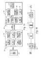
- FIG. 1Adepicts a power source, power supply, and electrical appliance.
- FIG. 1Bdepicts a prior art switched mode power converter.
- FIGS. 2A-2Ddepict power supplies.
- FIGS. 3A-3Ddepict electrical appliances.
- FIG. 4Adepicts a power supply and an electrical appliance
- FIGS. 4B and 4Cdepict interactions between the power supply and appliance.
- FIG. 5Adepicts first and second power supplies and an electrical appliance
- FIG. 5Bdepicts interactions between the appliance and the power supplies.
- FIG. 6Adepicts a power supply and an electrical appliance
- FIG. 6Bdepicts an interaction between the power supply and the appliance.
- FIG. 7Adepicts a power supply and an appliance
- FIG. 7Bdepicts an interaction between the power supply and the appliance.
- FIG. 8depicts an interaction between a power supply and an appliance.
- FIG. 9depicts an interaction between a power supply and an appliance.
- an apparatus 100includes a power supply 104 and an electrically powered appliance 106 .
- the electrically powered appliance 106may be any device that is powered by electrical power, including but not limited to devices configured for use in the consumer, commercial, or industrial environments.
- Non-limiting examples of electrically powered appliances 106include devices such as cellular or mobile telephones, domestic appliances, cordless telephones, answering machines, lighting devices, music or media players, personal digital assistants (PDAs), laptop, handheld, or notebook computers, optical bar code or other scanners, communications equipment, global positioning system (GPS) devices, and portable test and measurement equipment.
- the electrical appliance 106is configured as a human-portable device including a housing 107 that can be carried by, or otherwise moved under the power of, a human user.
- the appliance 106includes an electrical connector 110 that provides removable data and power connections to the power supply 104 or other external device(s) via suitable wires or cables.
- the connector 110may also be configured to include multiple connectors (e.g., physically separate data and power connectors). Power and data may also be transferred over the same wire(s) (e.g., using a suitable modulation scheme) or suitable wireless connection(s).
- Device electrical circuitry 120performs a function of the appliance 106 .
- the appliance 106may also include a rechargeable power source 122 such as one or more secondary (rechargeable) batteries, capacitive energy storage devices, or the like that supply operating power to the device electrical circuitry 120 , as well as a charger 124 that charges the storage device 122 .
- a rechargeable power source 122such as one or more secondary (rechargeable) batteries, capacitive energy storage devices, or the like that supply operating power to the device electrical circuitry 120 , as well as a charger 124 that charges the storage device 122 .
- the appliancemay also include one or more of appliance power requirements or other information 128 , a disconnect requester 130 , a load shifter 132 , and a mode controller 134 .
- the power supply 104which is likewise configured to be human-portable and includes a housing 103 , receives electrical power from an input power source 102 such as a standard 120/240 volt alternating current (VAC) 50/60 Hertz (Hz) power outlet, a vehicular power system such as a nominal 12 volt direct current (VDC) automobile electrical system, a renewable energy source such as a solar or wind source, mechanical source such as crank or vibration source, an infrared (IR) or heat source, an electromagnetic source, or other source of electrical power.
- the input power source 102typically includes an electrical connector 108 such as a standard wall or other electrical outlet, a 12 VDC power socket, or the like that allows various devices to be removably connected to the power source 102 . While the power supply 104 power rating is typically a function of the electrical appliance(s) 107 with which it is designed to operate, ratings ordinarily range between about 2 and 150 Watts (W), and often toward the lower end of the range.
- the power supply 104also includes an input power connector 112 such as a standard AC plug, 12 VDC power plug, or the like that matingly engages or otherwise connects to the connector 108 of the input power source 102 .
- a power converter 105converts power from the input power source 102 to the voltage and/or current levels required by the appliance 106 .
- the power supply 104includes a connector 114 that connects to the connector 110 of the appliance 106 . While only a single connector 114 and appliance 106 is illustrated, it will be understood that the power supply 114 may include a plurality of connectors 114 or otherwise be configured to concurrently connect with a plurality of appliances.
- suitable power converters 105include linear and switched-mode power converters.
- Linear power convertersare well suited for use with AC input sources 102 and typically include an input transformer that operates at the frequency of the input power source 102 (e.g., 50/60 Hz in the case of a power supply 104 configured to operate with a standard AC power outlet).
- Switched-mode power converterstypically include a relatively high speed semiconductor or other switch operatively connected to a reactor such as an inductor or capacitor.
- linear and switched mode power converter topologiesare known in the art and may selected based on application specific requirements. While linear power converters tend to be simple and robust, they also tend to be relatively bulky and inefficient. Though more complex, switched mode power converters are as a rule smaller and more energy efficient than comparable linear power converters. Moreover, switched mode power converters are generally better suited for use where the input power source 102 is a direct current (DC) source or where the power supply 104 is designed to operate with multiple power sources 102 (e.g., with both 120 VAC/60 Hz and 240 VAC/50 Hz systems).
- DCdirect current
- FIG. 1BA block diagram of an example switched mode power converter that includes closed loop feedback control is shown in FIG. 1B .
- an input rectifier and/or filter 150receives input power from a source such as the AC power mains, and the output of the rectifier is provided to a switch 152 that serves as an inverter or chopper.
- the chopperwhich typically operates at a switching frequency on the order of tens to hundreds of kilohertz (KHz), is connected electrically in series with the primary winding of a transformer 154 , and the transformer secondary winding(s) is connected to an output rectifier(s) and/or filter(s) 156 that produce a DC output signal.
- a closed loop controller 158controls an operation of the chopper 152 so as to regulate the power converter output voltage.
- the power supply 104may include one or more of a communication interface 136 that communicates with a connected appliance 106 , a power supply capability determiner 138 that determines or otherwise provides time varying or static information indicative of a power capability of the power supply 104 and/or a connected power source 102 , a load prioritizer 140 that prioritizes power provided to multiple appliances 106 in the case of a power supply 104 configured to concurrently connect to more than one appliance 106 , a load shifter 142 that shifts a load presented to the power supply 104 and/or the connected power source 102 , and a power converter disconnect 144 that selectively disconnects at least a portion of the power converter 105 from the input power source 102 .
- a communication interface 136that communicates with a connected appliance 106
- a power supply capability determiner 138that determines or otherwise provides time varying or static information indicative of a power capability of the power supply 104 and/or a connected power source 102
- a load prioritizer 140that prioritizes power provided
- a power supply 202is configured for power and data communication with a connected appliance 106 .
- the power supply 202includes power supply capability determiner 138 , a communication interface 136 , and a power converter 105 .
- the communication interface 136provides uni- or bi-directional communication with a connected appliance 106 .
- the communication interface 106is a universal serial bus (USB) interface
- the power supply 202serves as a USB powered host
- the connector 114is a standard USB connector though which data and power are provided to a connected appliance 106 .
- USBuniversal serial bus
- other serial, parallel, analog and digital communications interfaces 106are also contemplated.
- the power supply capability determiner 138determines or otherwise provides information indicative of the capabilities of the power supply 202 and/or an input power source 102 .
- the informationis static information describing a voltage, current, or power rating of the power supply 202 or a power source 102 .
- the informationincludes model number or similar identifying information that serves as a proxy for the power supply 202 capabilities.
- the power supply 202 capabilitiesmay also be time varying. Where the power supply 202 receives power from a solar or wind source, for example, the power available from the power converter 105 will typically vary as a function of factors such as incident light or wind speed.
- the determined power supply capabilitymay be communicated to a connected device 106 via the communication interface 206 , for example when an appliance 106 is initially connected to the power supply 202 , from time-to-time during operation of the devices, or the like.
- a second example power supply 220is configured for power communication with a connected appliance 106 . While the power supply includes a power converter 105 , it lacks a communication interface. As a consequence, the power supply 220 does not support communication with a connected appliance 106 that includes communication capabilities.
- a third example power supply 230is configured for data and power communications with a connected appliance 106 .
- the power supply 230includes a power converter 105 , a communication interface 136 a load shifter 142 , and a power converter disconnect 144 .
- the load shifter 142may be employed to defer, bring forward, or otherwise shift an operation of the appliance 106 from a time of high or peak demand or limited power availability to a time of relatively lower demand or greater power availability.
- Information regarding desired operating mode and/or load shifting operationsmay be communicated to and/or from a connected appliance 106 via the communication interface 136 , for example by sending suitable commands and/or signals to the appliance 106 .
- the power supply 230may also include a real time or other clock 210 , load shift schedule 212 , and device operating mode information 214 .
- the load shift schedule 212includes desired starting and ending time(s) or other parameters relevant to a load shifting operation.
- the operating mode information 214provides information indicative of possible operating mode(s) of appliance(s) 106 which the power supply 230 is designed to operate.
- Power converters 105typically draw power from the input power source 202 even where the power converter 105 is (substantially) unloaded, for example due to the non-ideal characteristics of transformers, switching devices, reactors, and other practical components. This power is ordinarily dissipated in the form of heat, and degrades system energy efficiency.
- the power converter disconnect 144selectively disconnects the power converter 105 from the input power source 102 .
- the power converter disconnect 144is operatively connected to a switch 235 such as an electromechanical switch or relay, semiconductor switching device, or the like located electrically in series between the input power source 102 and the power converter 105 .
- the switch 235may be integral thereto.
- the switch 235is also the inverter or chopper of a switched mode power converter, and the operation of the switch 235 is selectively enabled or disabled via suitable logic or other circuitry so as to disconnect some or all of the power converter 105 from the input power source 102 .
- the switch 235is located after a rectifier and/or filter.
- the power converter disconnect 144can be employed to automatically (i.e., without user intervention) reduce a power drawn by the power supply 230 from the power source 102 during periods of inactivity or reduced load, for example in the case of a connected appliance 106 that can be operated from a battery or other power source internal to the appliance 106 while in a low power operating mode, when a secondary (rechargeable) battery or other power source of the appliance 106 is fully or otherwise substantially charged, when an appliance 106 is not connected to the power converter 105 , in coordination with a load shifting operation, or the like.
- the power supply 230may include a rechargeable power source 236 that provides power to desired portions of the power converter 230 when the power converter circuit 105 is disabled. Operating power may also be obtained from the connected appliance 106 or a portion of the power converter circuit 105 that is not disabled. Note that the power supply 230 may also include a user operated power switch 238 that allows the user to manually disconnect the power supply 230 from the input power source 102 .
- the power supply 240includes as battery receiving region 242 configured to receive one or more generally cylindrical AAA, AA, C, D-size, or other suitable batteries. Battery contacts 246 make electrical contact with the battery 244 terminals. In one implementation, the batteries 244 supplant the power source 102 , in which case the connector 112 may be omitted. In another, the batteries 244 supply electrical power in the event of a power loss, if the power supply 240 is unplugged, or the like. While not explicitly illustrated in FIG. 2D , it will be understood that the power supply 240 may also include one or more of the power supply capability information 138 , load shifter 142 , power converter disconnect 144 , or load prioritizer 140 .
- FIG. 3AA first example electrically powered appliance 302 configured for power communication with a power supply 104 is shown in FIG. 3A .
- the appliance 302includes device electrical circuitry 120 , a rechargeable power source 122 , a charger 124 , and a connector 110 .
- the charger 124includes a state of charge detector that detects a state of charge of the energy source, for example by measuring a source voltage or current or, in the case of a timer based charger, an elapsed charging time.
- the device electrical circuitry 120may be omitted and the appliance 302 configured as a battery charger, in which case the appliance 302 ordinarily includes a battery receiving region 242 and battery contacts 246 analogous to those described above in relation to FIG. 2D and configured to accept batteries of the number and size(s) to be charged.
- batteriesare ordinarily inserted in the battery receiving region 242 for charging and removed for use in another device.
- the appliance 302does not support communication with a power supply 104 that includes communication capabilities.
- FIG. 3BA second example electrically powered appliance 320 configured for power and data communication with a power supply 104 is shown in FIG. 3B .
- the appliance 320includes a connector 110 , a data communication interface 322 , device electrical circuitry 120 , appliance requirements information 128 , a load shifter 132 , and a disconnect requester 130 .
- an optional power convertermay be used to convert the power from the power supply 104 to the required voltage and/or current levels.
- the load shifter 132performs a temporal load shifting operation and may operate in conjunction with one or more of an onboard clock(s), load shift schedule, and operating mode information.
- the load shifter 132causes the appliance 320 to perform a load shifting operation.
- the load shiftingis performed in response to a request communicated by a connected power supply 104 via the respective communications interfaces.
- the load shift operationis initiated by the load shifter 132 and optionally communicated to a connected power supply 104 .
- the disconnect requester 130generates a signal or other request to cause some or all of the power converter 105 of a connected power supply 104 to disconnect from its input power source 102 .
- the disconnect requestis generated when the device electrical circuitry 120 enters an inactive state or mode. Where, as illustrated, the appliance 302 lacks an energy storage device, initiating a disconnect request will ordinarily de-power the device electrical circuitry 120 .
- FIG. 3CAnother example of an electrically powered appliance 340 configured for data and power communication with a connected power supply 104 is shown in FIG. 3C .
- the appliance 340includes a charger 124 , rechargeable power source 122 , and device electrical circuitry.
- the appliance 340also includes a communication interface 126 , load shifter 132 , mode controller 134 , and a disconnect requester 130 .
- the disconnect requester 130is operatively connected to the charger 124 , for example to generate a disconnect request when the rechargeable power source 122 is substantially or otherwise suitably charged.
- the disconnect requester 130may also from time-to-time generate a reconnect request, for example to maintain the storage device 122 state of charge.
- the appliance 340includes an energy storage device 122 , at least a portion of the device electrical circuitry 120 remains substantially functional when the appliance 340 is disconnected from a power source 104 or where a power converter 105 is disconnected from the input power source 102 .
- the mode controller 134controls an operating mode of the device electrical circuitry 120 .
- the mode controller 134varies an operating mode of the appliance in response to a signal generated by a connected power supply 104 and communicated via the respective communication interface.
- the mode controller 134may restrict the device electrical circuitry 120 to a relatively low power or otherwise limited operating mode(s) when the appliance is not connected to a power supply 104 .
- FIG. 3DAnother example of an electrically powered appliance 350 is shown in FIG. 3D .
- the appliance 350includes a connector 110 and a device electrical circuitry 120 .
- the appliance 350does not include a communication interface or an energy storage device, the appliance 350 does not support data communication with a connected power supply 104 and is ordinarily non-functional when not connected to a power supply 104 .
- the various power supplies 202 , 220 , 230 , 240 and electrical appliances 302 , 320 , 340 , 350may form a family of generally interoperable devices, noting again the features and combinations of features described above are presented for the purpose of illustration and may be varied to suit the requirements of a particular application.
- a given electrical appliancemay be configured to operate with some or all of the power supplies 202 , 220 , 230 , 240 .
- a given power supplymay be configured to operate with some or all of the electrical appliances 302 , 320 , 340 , 350 .
- the connectors 114 , 110 of the power supplies and electrical appliancesare preferably physically compatible, and the communications interfaces operate according to a common communication protocol.
- a power supply 104 and electrical appliance 106undergo a detection and/or identification process (e.g., an enumeration process in the case of devices having a USB interface) in which those devices having a communication interface seek to identify the device to which it is connected and determine power requirements.
- a detection and/or identification processe.g., an enumeration process in the case of devices having a USB interface
- those devices having a communication interfaceseek to identify the device to which it is connected and determine power requirements.
- the communicative deviceenters into a default or otherwise pre-defined mode of operation. Where two communicative devices are connected, the devices interact accordingly.
- a power supply 402is configured as a wall plug adapter that plugs into a standard 120 VAC wall or other outlet 406
- an electrical appliance 404is a consumer electronic device such as a cellular or mobile telephone that includes a rechargeable battery.
- the adapter 402includes a generally rectangular prismatic housing 408 having a standard AC power plug that protrudes from a surface of the housing 408 so as to plug into the outlet 406 .
- a connector 412 located at the distal end of a cable 414removably engages a corresponding connector of the mobile phone 404 .
- the power supply 402is configured as described in FIG. 2B and the appliance 404 is configured as described in FIG. 3A .
- the device 402 , 404 interactionwill now be described with reference to FIG. 4B , it being assumed that the power supply 402 is already plugged in to the outlet 406 .
- the power supply 402 and the appliance 404are connected.
- power from the power supply 402is used to charge the appliance 404 battery.
- the devicesare disconnected, and the appliance 404 is operated at step 426 . Of course, the process may be repeated as desired.
- the foregoingdescribes a conventional interaction between a wall plug adapter and a mobile phone. While such an interaction has proven to be effective for charging the appliance 404 battery, there nonetheless remains room for improvement.
- the power converter circuitry 105 of the wall plug adapter 402remains connected to the power mains 406 even after the battery of the mobile phone 404 is substantially fully charged, thus reducing the overall energy efficiency of the arrangement.
- Trickle charging of the batteryif provided, further reduces the energy efficiency.
- such an arrangementdoes not support operations such as load shifting.
- the wall power supply 402is configured as described in FIG. 2C
- the appliance 404includes a charger 124 , rechargeable power source 122 , device electrical circuitry 120 , a communications interface 126 , and a disconnect requester 130 .
- a device 402 , 404 interaction that includes a power supply disconnection and reconnection operationwill now be described with reference to FIG. 4C , it again being assumed that the power supply 402 is already plugged into the outlet 406 but that the power converter 105 is disconnected from the AC power line.
- the power supply 402 and appliance 404are connected at step 430 .
- the devicesundergo a detection and/or identification procedure 432 , for example to detect the other the connected device and identify its capabilities.
- the power supply power converter 105is connected to the AC power line at step 434 .
- the power supply 402supplies power to the appliance 404 , with the supplied power being used to charge the storage device 122 .
- the state of charge of the storage device 122is determined at 437 , for example by monitoring a device 122 voltage or current, determining an elapsed charge time in the case of a timer based charger, or the like. If the storage device 122 is not sufficiently charged, the charging process continues at step 436 .
- the storage device 122is substantially or otherwise sufficiently charged, at least a portion of the power converter circuit 105 is disconnected from the AC power mains 406 at step 438 .
- a disconnect, charge complete, or other suitable signalis communicated from the appliance 404 to the power supply 402 via the devices' respective communication interfaces.
- appliance 404may be configured to communicate such a signal even though the power supply 402 does not include a communication interface or support a power converter disconnection operation, in which case the request would not be honored.
- the state of charge detectoris included in the power supply 402 , and the power converter 105 is disconnected accordingly.
- the storage device 122 state of chargeis maintained at step 440 .
- the state of chargemay be determined as described above in step 437 . If a maintenance or additional charge is required, a connect, charge required, or other suitable signal may be communicated to the power supply 402 via the communication interfaces. Where the state of charge is monitored by the power supply 402 , the power converter 105 is connected accordingly. The process returns to step 434 .
- the appliance 404 and power supply 402are disconnected, and the appliance 404 is operated at step 444 .
- the disconnection of the appliancemay be detected and the power converter disconnected accordingly. The process may be repeated as desired.
- disconnecting the power converter 105 during periods of inactivity, in which the electrical appliance 404 presents a relatively low load, or where the appliance 404 is not connected to the power supply 402 , and reconnecting the power converter from time-to-time on an as needed basistends to improve the overall energy efficiency of the system.
- the processbe used in connection with appliances other than mobile phones and the connection and reconnection performed for purposes other than maintaining a battery state of charge.
- the appliance 404may alternate between a relatively low power or sleep mode and a relatively higher operating mode, with the power converter 105 being disconnected and reconnected accordingly.
- an example family of devicesincludes a first power supply 502 , a second power supply 504 , and an electrical appliance 506 .
- the first power supply 502is a wall plug adapter similar to that described above in connection with FIG. 4A .
- the second power supply 504which is configured to connect to an input power source having a relatively lower power capability such as a power port 508 of a 12 VDC vehicular power system, includes a standard 12 VDC power connector 510 and an appliance connector 512 .
- the electrical appliance 506includes at least a first relatively high power operating mode and a second relatively low power operating mode. Where the appliance 506 is configured as or includes a battery charger, for example, the electrical appliance may include a relatively high power fast charging mode and a relatively low power slow charging mode. As another example, a lighting appliance may include high and low brightness modes.
- the first 502 and second 504 power suppliesare both configured as described above in relation to FIG. 2A
- the electrical appliance 506is configured as described in relation to FIG. 3C .
- An interaction between the appliance 506 and the power supplies 502 , 504 that includes a capability determination and operating mode adjustment operationwill now be described with reference to FIG. 5B .
- the electrical appliance 506 and a desired power supply 502 , 504are connected at step 520 .
- the devicesundergo a detection and/or identification procedure to determine the capability of the connected power supply 502 , 504 and/or its input power source.
- the appliance 506enters into an operating mode consistent with the determined capabilities of the connected power supply 502 , 504 . Where the appliance is connected to the first power supply 502 , for example, the appliance enters the relatively high power operating mode. If the appliance is connected to the second power supply 504 , the appliance 506 enters the low power operating mode.
- the electrical appliance 506 and power supplyare disconnected.
- the applianceis operated as desired at 528 . Again, the process may be repeated as desired.
- FIG. 6Aan example input power source 602 , power supply 604 , and appliance 606 are connected as shown.
- the power supplyis configured as shown in FIG. 2B and that the appliance 606 is configured as shown in FIG. 3A .
- An example interaction between the devices that includes a charging discontinuation operationwill now be described with reference to FIG. 6B .
- the power supply 604 and appliance 606are connected at 608 .
- the connected devicesundergo a detection and/or identification procedure.
- the appliance 606will recognize that it is connected to power supply 604 that does not support communications and enters a suitable default or otherwise pre-defined operating mode.
- power from the power supply 604is used to charge the appliance 606 battery.
- the battery state of chargeis determined at 614 . If the battery is not substantially or otherwise suitably charged, the process continues to step 612 .
- chargingis discontinued at 616 , and the process returns to step 614 .
- the appliance 606is disconnected from the power supply 604 at 618 and may be operated as desired at step 618 . The process may be repeated as desired.
- an example power supply 700includes a solar cell or other solar power source 702 , a power converter 105 , and power supply capability determiner 138 .
- the appliance 704is configured substantially as described in FIG. 3C .
- a device 700 , 704 interaction that includes a dynamic power capability determination and operating mode adjustmentwill now be described with reference to FIG. 7B .
- the power supply 700 and appliance 704are connected at 710 .
- the then-current power capability of the power supply 702is detected and communicated to the appliance 704 via the respective communication interfaces.
- the appliance 704enters an operating mode consistent with the communicated capability, and the process continues to step 712 .
- the appliance 704 and power supply 706are disconnected, and the appliance is operated as desired at 718 .
- the processmay be repeated as desired.
- the appliance 704is described as including functionality such as a load shifter 132 and disconnect requester 130 that are not supported by the power supply 702 .
- the functions supported by the devices 702 , 704are determined as part of an initial device identification step, with the operation of the appliance 704 adjusted accordingly.
- the appliance 704does not determine the functions supported by the power supply 702 and is configured to present load shift, disconnect, or other requests even though such requests may not be recognized or acted upon by the power supply 702 .
- the appliance and power supplyare physically connected at 802 .
- the load shift requirementsare determined at 804 , for example by reference to a load shift schedule, operating mode, and other information maintained in one or both of the power supply and appliance, with the desired load shift operation being communicated via the respective communications interfaces.
- An operation of the applianceis temporally shifted at 806 .
- a desired operation of the appliancemay be deferred until a time at which the input power source is subject to a relatively low power demand.
- a requested charging operationmay be restricted to a relatively slow, low power mode during a designated high or peak demand period (e.g., in the middle of the day for a typical AC power system) but permitted to operate in a relatively faster, high power mode during a period of relatively reduced demand (e.g., during the night). The process may be repeated as desired.
- the appliancemay also be disconnected from the power supply and operated as desired as indicated at 810 and 812 respectively.
- the power supply and a first applianceare connected at 902 .
- the power supply and applianceundergo a detection and/or identification operation at 904 .
- the first devicemay be identified as a portable music player including a rechargeable battery via a signal communicated over the devices' respective communication interfaces.
- the first applianceis operated at 906 .
- the power supply and a second applianceare connected at 908 .
- the power supply and applianceundergo a detection and/or identification operation at 910 .
- the second devicemay be identified as a portable emergency light also including a rechargeable battery by way of a signal communicated over the devices respective communication interfaces.
- the appliancesare prioritized at 912 , for example by applying a set of priority rules applicable to various devices in a case where the power supply has insufficient capability to concurrently power both devices.
- the priority rulesmay provide that the emergency light takes precedence over the music player.
- the appliancesare operated according to the determined priority.
- the power supplymay cause a first operating mode or priority signal to be communicated to the emergency light via the devices' respective communication interface so as to cause a charger of the emergency light to charge (or continue charging) the emergency light battery.
- supplymay cause a second operating mode or priority signal to be communicated to the music player so as to cause a charger of the emergency light to defer charging of the music player battery.
- power supplyalters a charging energy applied to the devices, for example by limiting a charging voltage or current applied to the lower priority device.
Landscapes
- Engineering & Computer Science (AREA)
- Power Engineering (AREA)
- Business, Economics & Management (AREA)
- Emergency Management (AREA)
- Charge And Discharge Circuits For Batteries Or The Like (AREA)
- Direct Current Feeding And Distribution (AREA)
Abstract
Description
Claims (38)
Priority Applications (4)
| Application Number | Priority Date | Filing Date | Title |
|---|---|---|---|
| US11/850,380US7960944B2 (en) | 2007-09-05 | 2007-09-05 | Power supply that supplies power to and communicates with an electrical appliance |
| CN200880105839.4ACN101796703B (en) | 2007-09-05 | 2008-08-15 | Interaction between smart devices and power sources |
| PCT/US2008/009797WO2009032058A2 (en) | 2007-09-05 | 2008-08-15 | Intelligent device and power source interaction |
| EP08795379.0AEP2186180B1 (en) | 2007-09-05 | 2008-08-15 | Intelligent device and power source interaction |
Applications Claiming Priority (1)
| Application Number | Priority Date | Filing Date | Title |
|---|---|---|---|
| US11/850,380US7960944B2 (en) | 2007-09-05 | 2007-09-05 | Power supply that supplies power to and communicates with an electrical appliance |
Publications (2)
| Publication Number | Publication Date |
|---|---|
| US20100264875A1 US20100264875A1 (en) | 2010-10-21 |
| US7960944B2true US7960944B2 (en) | 2011-06-14 |
Family
ID=40429593
Family Applications (1)
| Application Number | Title | Priority Date | Filing Date |
|---|---|---|---|
| US11/850,380Active2030-03-29US7960944B2 (en) | 2007-09-05 | 2007-09-05 | Power supply that supplies power to and communicates with an electrical appliance |
Country Status (4)
| Country | Link |
|---|---|
| US (1) | US7960944B2 (en) |
| EP (1) | EP2186180B1 (en) |
| CN (1) | CN101796703B (en) |
| WO (1) | WO2009032058A2 (en) |
Cited By (40)
| Publication number | Priority date | Publication date | Assignee | Title |
|---|---|---|---|---|
| US20100134305A1 (en)* | 2008-11-26 | 2010-06-03 | Vbi 2000, Llc | Intelligent adaptive energy management system and method for a wireless mobile device |
| US20100164430A1 (en)* | 2008-12-31 | 2010-07-01 | Vbi 2000, Llc | Intelligent Adaptive Energy Management System and Method for Using |
| US20100213895A1 (en)* | 2009-02-24 | 2010-08-26 | Qualcomm Incorporated | Wireless power charging timing and charging control |
| US20100253281A1 (en)* | 2009-04-07 | 2010-10-07 | Qualcomm Incorporated | Wireless power transmission scheduling |
| US20110018494A1 (en)* | 2009-07-22 | 2011-01-27 | Sony Corporation | Power receiving apparatus, power transmission system, charging apparatus and power transmission method |
| US20110115306A1 (en)* | 2008-07-25 | 2011-05-19 | BSH Bosch und Siemens Hausgeräte GmbH | Domestic appliance, especially a dishwasher or washer |
| US20120166008A1 (en)* | 2010-12-22 | 2012-06-28 | Electronics And Telecommunications Research Institute | Smart grid power controller and power control method for the same |
| US20120169272A1 (en)* | 2011-01-03 | 2012-07-05 | David Khalepari | Portable usb mini-charger device |
| US20130015808A1 (en)* | 2011-07-15 | 2013-01-17 | Samsung Electronics Co. Ltd. | Device and method for charging a master device using a detachable device |
| US8758031B2 (en) | 2012-04-19 | 2014-06-24 | Pass & Seymour, Inc. | Electrical wiring device with high current USB charging capabilities |
| US20140191588A1 (en)* | 2013-01-08 | 2014-07-10 | Hzo, Inc. | Apparatuses, systems, and methods for reducing power to ports of electronic devices |
| US9071046B2 (en) | 2012-01-10 | 2015-06-30 | Hzo, Inc. | Methods, apparatuses and systems for monitoring for exposure of electronic devices to moisture and reacting to exposure of electronic devices to moisture |
| US9157880B2 (en) | 2013-01-08 | 2015-10-13 | Hzo, Inc. | Apparatuses, systems, and methods for detecting and reacting to exposure of an electronic device to moisture |
| US9263893B2 (en) | 2011-02-25 | 2016-02-16 | Panasonic Intellectual Property Management Co., Ltd. | Electricity storage device, electricity storage control method, management device, management method, and electricity storage system |
| US20160077137A1 (en)* | 2012-06-12 | 2016-03-17 | Namki LEE | Home appliance having built-in power meter |
| US9368982B2 (en) | 2013-07-31 | 2016-06-14 | Leviton Manufacturing Co., Inc. | Wiring device having a housing with multiple portions and low voltage ports |
| US20170061554A1 (en)* | 2014-02-21 | 2017-03-02 | Orange | Device for powering an electrical appliance |
| US10541529B2 (en) | 2012-01-10 | 2020-01-21 | Hzo, Inc. | Methods, apparatuses and systems for sensing exposure of electronic devices to moisture |
| US20220052544A1 (en)* | 2020-08-14 | 2022-02-17 | Cirrus Logic International Semiconductor Ltd. | Reverse wireless charging power management |
| US11334131B2 (en) | 2018-07-25 | 2022-05-17 | Hewlett-Packard Development Company, L.P. | Power management in power adapters to deliver power to a power output coupled to an electronic device in accordance with power supply capability information |
| US11476711B2 (en) | 2020-12-23 | 2022-10-18 | Nucurrent, Inc. | Wireless power transmitters and associated base stations for through-structure charging |
| US11476722B2 (en) | 2020-04-30 | 2022-10-18 | Nucurrent, Inc. | Precision power level control for extended range wireless power transfer |
| US11482891B1 (en) | 2021-04-20 | 2022-10-25 | Nucurrent, Inc. | Timing verification in precision power level control systems for wireless power transmission |
| US11482890B2 (en) | 2020-04-30 | 2022-10-25 | Nucurrent, Inc. | Surface mountable wireless power transmitter for transmission at extended range |
| US20220352763A1 (en)* | 2021-04-30 | 2022-11-03 | Nucurrent, Inc. | Power Capability Detection For Wireless Power Transmission Based On Receiver Power Request |
| US11532956B2 (en) | 2021-04-30 | 2022-12-20 | Nucurrent, Inc. | Power capability detection with verification load in power level control systems for wireless power transmission |
| US11539247B2 (en) | 2021-04-30 | 2022-12-27 | Nucurrent, Inc. | Power capability detection in precision power level control systems for wireless power transmission |
| US20230088001A1 (en)* | 2021-09-21 | 2023-03-23 | Abb Schweiz Ag | Protected Charging Connector |
| US11637448B1 (en) | 2021-10-12 | 2023-04-25 | Nucurrent, Inc. | Wireless power transmitter with removable magnetic connector panel for vehicular use |
| US11637459B2 (en) | 2020-12-23 | 2023-04-25 | Nucurrent, Inc. | Wireless power transmitters for transmitting power at extended separation distances utilizing T-Core shielding |
| US11757313B2 (en) | 2020-04-30 | 2023-09-12 | Nucurrent, Inc. | Operating frequency based power level altering in extended range wireless power transmitters |
| US11757311B2 (en) | 2020-12-23 | 2023-09-12 | Nucurrent, Inc. | Wireless power transmitters and associated base stations for transmitting power at extended separation distances |
| US11831179B2 (en) | 2020-12-23 | 2023-11-28 | Nucurrent, Inc. | Wireless power transmitters and associated base stations for transmitting power at extended separation distances |
| US11837875B2 (en) | 2020-12-23 | 2023-12-05 | Nucurrent, Inc. | Wireless power transmitters for transmitting power at extended separation distances utilizing concave shielding |
| US11942799B2 (en) | 2021-04-30 | 2024-03-26 | Nucurrent, Inc. | False notification suppression in wireless power transfer system |
| US11967830B2 (en) | 2021-10-12 | 2024-04-23 | Nucurrent, Inc. | Wireless power transmitters for transmitting power at extended separation distances with magnetic connectors |
| US12074464B2 (en) | 2018-09-18 | 2024-08-27 | Leviton Manufacturing Co., Inc. | Systems and methods for Universal Serial Bus (USB) power delivery with multiple charging ports |
| US12119701B2 (en) | 2018-09-18 | 2024-10-15 | Leviton Manufacturing Co., Inc. | Systems and methods for universal serial bus (USB) power delivery with multiple charging ports |
| US12132325B2 (en) | 2021-10-12 | 2024-10-29 | Nucurrent, Inc. | Wireless power transmitter with removable magnetic connector panel |
| US12292216B2 (en) | 2014-11-25 | 2025-05-06 | B Medical Systems S.à.r.l. | Cooling device |
Families Citing this family (30)
| Publication number | Priority date | Publication date | Assignee | Title |
|---|---|---|---|---|
| US7522878B2 (en)* | 1999-06-21 | 2009-04-21 | Access Business Group International Llc | Adaptive inductive power supply with communication |
| US8261100B2 (en)* | 2006-08-30 | 2012-09-04 | Green Plug, Inc. | Power adapter capable of communicating digitally with electronic devices using packet-based protocol |
| US7843088B2 (en) | 2008-03-07 | 2010-11-30 | Harry Leonard Perper | Energy conserving (stand-by mode) power saving design for battery chargers and power supplies |
| US20100001689A1 (en)* | 2008-07-02 | 2010-01-07 | Anton/Bauer, Inc. | Modular charger |
| US8519671B2 (en)* | 2008-09-15 | 2013-08-27 | Blackberry Limited | Power supply circuit and method for providing output voltage to charge a battery |
| US20100228687A1 (en)* | 2009-03-03 | 2010-09-09 | Lewis Jr Donald Davis | Electricity Vending Devices And Associated Methods |
| JP5499534B2 (en)* | 2009-07-07 | 2014-05-21 | ソニー株式会社 | Non-contact power receiving apparatus, power receiving method in non-contact power receiving apparatus, and non-contact power feeding system |
| US8222861B1 (en)* | 2010-02-08 | 2012-07-17 | Lockheed Martin Corporation | Elimination of power consumption when charger/adaptor is not in use |
| US20110254383A1 (en)* | 2010-04-16 | 2011-10-20 | Motorola, Inc. | Smart module and method with minimal standby loss |
| EP2587734B1 (en)* | 2010-06-26 | 2015-04-08 | LG Electronics Inc. | Network system |
| CN102884700B (en)* | 2010-07-28 | 2016-01-20 | 松下知识产权经营株式会社 | Electric power supply system, control device for electric power supply system, operation method of electric power supply system, and control method of electric power supply system |
| CN201928060U (en)* | 2010-09-19 | 2011-08-10 | 徐忠方 | Intelligent wall-type charger |
| US8942835B2 (en) | 2011-06-16 | 2015-01-27 | Bsh Home Appliances Corporation | System and method of operating household appliances |
| FR2980055B1 (en)* | 2011-09-12 | 2013-12-27 | Valeo Systemes Thermiques | INDUCTIVE POWER TRANSMISSION DEVICE |
| US8384359B2 (en)* | 2011-10-21 | 2013-02-26 | General Electric Company | System, charging device, and method of charging a power storage device |
| US9805890B2 (en)* | 2011-11-07 | 2017-10-31 | Cooper Technologies Company | Electronic device state detection for zero power charger control, systems and methods |
| DE102012200927A1 (en)* | 2012-01-23 | 2013-07-25 | Siemens Aktiengesellschaft | Energy management in distribution networks via wireless communication |
| CN102738831B (en)* | 2012-07-17 | 2015-06-03 | 友达光电股份有限公司 | Solar system and communication device |
| JP6127668B2 (en)* | 2013-04-08 | 2017-05-17 | ソニー株式会社 | Electronic equipment and power supply system |
| HK1218808A1 (en)* | 2013-04-12 | 2017-03-10 | Nokia Technologies Oy | A wireless charger |
| EP3101768B1 (en)* | 2014-01-28 | 2021-05-26 | Guangdong Oppo Mobile Telecommunications Corp., Ltd. | Power adapter and terminal |
| US10148096B2 (en)* | 2014-07-07 | 2018-12-04 | Mediatek Singapore Pte. Ltd. | Wireless or wired power delivery using a controllable power adapter |
| EP3029068A1 (en) | 2014-12-03 | 2016-06-08 | EngMab AG | Bispecific antibodies against CD3epsilon and BCMA for use in the treatment of diseases |
| EP3231076B1 (en)* | 2014-12-08 | 2025-07-23 | B/E Aerospace, Inc. | Quasi-resonant magnetron power supply |
| JP6555739B2 (en)* | 2015-06-05 | 2019-08-07 | Fdk株式会社 | Charger |
| CN105472849A (en)* | 2015-12-30 | 2016-04-06 | 镇江船舶电器有限责任公司 | Marine emergency lighting maintenance and management system |
| JP6764541B2 (en)* | 2017-03-02 | 2020-09-30 | シグニファイ ホールディング ビー ヴィSignify Holding B.V. | Wireless power distribution controllers and methods for controlling wireless power supply |
| EP3642931A4 (en)* | 2017-06-20 | 2020-12-09 | Hubbell Incorporated | System and method for controlling an electrical receptacle |
| CN107749650A (en)* | 2017-10-26 | 2018-03-02 | 成都优购科技有限公司 | Audio separator intelligent charging system reasonable in design |
| CN108899984A (en)* | 2018-08-02 | 2018-11-27 | 天津檀英科技有限公司 | Power supply system and power supply method for mobile house |
Citations (11)
| Publication number | Priority date | Publication date | Assignee | Title |
|---|---|---|---|---|
| US5130634A (en) | 1989-07-05 | 1992-07-14 | Nec Corporation | Battery charger for a portable wireless telephone set having means for tricklingly charging the battery with an increased current during a stand-by period of the telephone set |
| EP0711015A2 (en) | 1994-11-04 | 1996-05-08 | Hewlett-Packard Company | Method and apparatus for charging a plurality of batteries for an electronic device |
| US5734252A (en) | 1996-12-20 | 1998-03-31 | Ericsson, Inc. | Method and apparatus for charging a battery of an electronic device using an intelligent external charger |
| KR19990077666A (en) | 1998-03-10 | 1999-10-25 | 이데이 노부유끼 | Power supplying adapter, electronic equipment, and signal transmission system |
| US6078871A (en) | 1998-01-15 | 2000-06-20 | Micron Electronics, Inc. | Method of displaying a status condition of a battery |
| US6184652B1 (en) | 2000-03-14 | 2001-02-06 | Wen-Chin Yang | Mobile phone battery charge with USB interface |
| EP1146621A2 (en) | 2000-04-14 | 2001-10-17 | Zip Charge Co., Ltd. | Charging apparatus |
| US6362610B1 (en) | 2001-08-14 | 2002-03-26 | Fu-I Yang | Universal USB power supply unit |
| US6507172B2 (en) | 2001-03-19 | 2003-01-14 | Maxim Integrated Products, Inc. | Universal serial bus powered battery charger |
| US20050174094A1 (en) | 2004-02-11 | 2005-08-11 | Research In Motion Limited, A Canadian Corporation | Battery charger for portable devices and related methods |
| US20060098460A1 (en) | 2000-03-02 | 2006-05-11 | Balu Balakrishnan | Switched mode power supply responsive to current derived from voltage across energy transfer element input |
Family Cites Families (7)
| Publication number | Priority date | Publication date | Assignee | Title |
|---|---|---|---|---|
| US4211933A (en)* | 1978-05-26 | 1980-07-08 | Cyborex Laboratories, Inc. | Electrical load restoration method |
| US5761083A (en)* | 1992-03-25 | 1998-06-02 | Brown, Jr.; Robert J. | Energy management and home automation system |
| US20040075343A1 (en)* | 2002-09-05 | 2004-04-22 | Paul Wareham | System and method for power load management |
| JP4148183B2 (en)* | 2004-05-18 | 2008-09-10 | 日立工機株式会社 | Charger |
| US7514815B2 (en)* | 2004-09-28 | 2009-04-07 | American Power Conversion Corporation | System and method for allocating power to loads |
| US7274975B2 (en)* | 2005-06-06 | 2007-09-25 | Gridpoint, Inc. | Optimized energy management system |
| KR100801042B1 (en)* | 2005-09-02 | 2008-02-11 | 김선영 | Auto power off outlet |
- 2007
- 2007-09-05USUS11/850,380patent/US7960944B2/enactiveActive
- 2008
- 2008-08-15CNCN200880105839.4Apatent/CN101796703B/ennot_activeExpired - Fee Related
- 2008-08-15EPEP08795379.0Apatent/EP2186180B1/ennot_activeNot-in-force
- 2008-08-15WOPCT/US2008/009797patent/WO2009032058A2/enactiveApplication Filing
Patent Citations (12)
| Publication number | Priority date | Publication date | Assignee | Title |
|---|---|---|---|---|
| US5130634A (en) | 1989-07-05 | 1992-07-14 | Nec Corporation | Battery charger for a portable wireless telephone set having means for tricklingly charging the battery with an increased current during a stand-by period of the telephone set |
| EP0711015A2 (en) | 1994-11-04 | 1996-05-08 | Hewlett-Packard Company | Method and apparatus for charging a plurality of batteries for an electronic device |
| US5734252A (en) | 1996-12-20 | 1998-03-31 | Ericsson, Inc. | Method and apparatus for charging a battery of an electronic device using an intelligent external charger |
| US6078871A (en) | 1998-01-15 | 2000-06-20 | Micron Electronics, Inc. | Method of displaying a status condition of a battery |
| KR19990077666A (en) | 1998-03-10 | 1999-10-25 | 이데이 노부유끼 | Power supplying adapter, electronic equipment, and signal transmission system |
| US20060098460A1 (en) | 2000-03-02 | 2006-05-11 | Balu Balakrishnan | Switched mode power supply responsive to current derived from voltage across energy transfer element input |
| US7193865B2 (en) | 2000-03-02 | 2007-03-20 | Power Integrations, Inc. | Switched mode power supply responsive to current derived from voltage across energy transfer element input |
| US6184652B1 (en) | 2000-03-14 | 2001-02-06 | Wen-Chin Yang | Mobile phone battery charge with USB interface |
| EP1146621A2 (en) | 2000-04-14 | 2001-10-17 | Zip Charge Co., Ltd. | Charging apparatus |
| US6507172B2 (en) | 2001-03-19 | 2003-01-14 | Maxim Integrated Products, Inc. | Universal serial bus powered battery charger |
| US6362610B1 (en) | 2001-08-14 | 2002-03-26 | Fu-I Yang | Universal USB power supply unit |
| US20050174094A1 (en) | 2004-02-11 | 2005-08-11 | Research In Motion Limited, A Canadian Corporation | Battery charger for portable devices and related methods |
Non-Patent Citations (30)
| Title |
|---|
| Alan Meier, Final Report Research Recommendations to Achieve Energy Savings for Electronic Equipment Operating in Lower Power Modes, Sep. 30, 2002, pp. cover page-10. |
| Andrew Fanara, Letter from the United States Environmental Protection Agency Office of Air and Radiation, Oct. 17, 2005, 2 sheets. |
| Bill Moore, The Potential of Plug-in Hybrids, EV World, Oct./Nov. 2005, 4 sheets. |
| California Energy Commission, California Standards for External Power Supplies, Mar. 3, 2005, 4 sheets. |
| Calwell et al., Power Supplies: A Hidden Opportunity for Energy Savings, NRDC Report, May 22, 2002, pp. cover page-22. |
| Dallas Semiconductor, Charging Batteries Using USB Power, Maxim application note 3241, May 25, 2004, 7 pages. |
| David Friedman, Declaring Oil Independence, reprinted from Oct./Nov. 2005 issue of Mother Earth News, Oct. 5, 2005, 2 sheets. |
| Energy Star, Energy Star Program Requirements for Products with Battery Charging Systems (BCSs) Draft 2 Eligibility Criteria, downloaded Jul. 24, 2007, pp. 1-9. |
| Energy Star, Energy Star Program Requirements for Single Voltage External Ac-Dc and Ac-Ac Power Supplies Eligibility Criteria, downloaded Jul. 26, 2007, pp. 1-6, version 1.1. |
| Energy Star, Test Methodology for Determining the Energy Performance of Battery Charging System,Draft, Oct. 2005, pp. 1-5. |
| Instructables, MintyBoost!-Small battery-powered USB charger, May 30, 2006, 20 sheets, http://www.instructables.com/id/EGBQJPLCB2EP287KTZ/?ALLSTEPS. |
| Len Sherman, Charge Your Battery Faster by Using a USB Port, Power Electronic Technology, Jan. 2004, pp. 34-40, www.powerelectronics.com. |
| Matt Chapman, Carphone Wharehouse leads to green charge, Absolute Gadget, Sep. 4, 2007, 1 sheet, http://www.absolutegadget.com/index2.php?option=com-content&task=view&id=753&pop... |
| Maxim Integrated Products, SOT23 Dual-Input USB/AC Adapter 1-Cell Li+ Battery Chargers, MAX1551/MAX1555, Jul. 2003, pp. 1-7, Rev. 0, USA. |
| Maxim, Dual-Input, USB/AC Adapter, 1-Cell Li+ Charger with OVP and Thermal Regulation, MAX1874, Jul. 2003, pp. 1-16. |
| Morison, David. Battery-Charger ICs are Tailored for Latest Application, Power Electronics Technology, May 2005, pp. 54-55, www.powerelectronics.com. |
| Nokia, Nokia becomes the first phone maker to add energy saving alerts to mobiles, Nokia press release, May 10, 2007, 1 sheet, www.nokia.com. |
| Patent Cooperation Treaty (PCT), International Search Report and Written Opinion for Application No. PCT/US2007/024133, filed Nov. 19, 2007, mailed Aug. 20, 2008, European Patent Office, Netherlands. |
| Patent Cooperation Treaty (PCT), International Search Report and Written Opinion for Application No. PCT/US2008/009797, filed Aug. 15, 2008, mailed Mar. 3, 2009, Korean Intellectual Property Office, Republic of Korea. |
| Philips Semiconductors, UBS On-The-Go: A Tutorial, White Paper, Jan. 2002, 9 sheets. |
| Power Integration, TNY 263-268 TinySwitch-II Family Enhanced, Energy Efficient Low Power Off-line Switcher, data sheet, Apr. 2005, pp. 1-24. |
| Power Integrations, Recent Technology Advancements in Reducing Standby Power, presentation, Nov. 2006, slides 1-21, www.powerint.com. |
| Power Integrations, TOP242-250 TOPSwitch-GX Family Extended Power, Design Flexible EcoSmart, Integrated Off-line Switcher, data sheet, Nov. 2005, pp. 1-52. |
| Robert Sanders, Eliminating "standby" electricity loss from home appliances could save up to 25 percent on electrical bills, study shows, University of California Berkeley press release, Feb. 9, 2001, 3 sheets, http://www.berkeley.edu/news/media/releases/2001/02/09-energ.html. |
| Texas Instruments, Single-Chip Charger and DC/DC Converter IC for Bluetooth Headsets and Other Portable Applications (bq2501x), data sheet, Mar. 2005, 24 sheets. |
| Think Geek, Fundue-desktop USB Fondue set main description, downloaded on or before Nov. 12, 2006, 3 pages, http://www.thinkgeek.com/stuff/41/fundue.shtml. |
| Think Geek, George Foreman, USB iGrill main description, downloaded on or before Nov. 27, 2006, 2 pages, http://www.thinkgeek.com/stuff/loofirpa/igrill.shtml. |
| USB-IF, Battery Charging Specification, Mar. 8, 2007, pp. cover page-25, rev. 1.0. |
| Wikipedia, The Free Encyclopedia, Universal Serial Bus, page last modified Nov. 10, 2006, 28 pages, http://en.wikipediattp.org/wiki/usb-connection. |
| Will Anderson, How Much Electricity Do You Waste At Home? A New Meter Reveals The, The (London) Independent, Jun. 21, 2006, 3 sheets. |
Cited By (62)
| Publication number | Priority date | Publication date | Assignee | Title |
|---|---|---|---|---|
| US8860256B2 (en)* | 2008-07-25 | 2014-10-14 | Bsh Bosch Und Siemens Hausgeraete Gmbh | Domestic appliance, especially a dishwasher or washer |
| US20110115306A1 (en)* | 2008-07-25 | 2011-05-19 | BSH Bosch und Siemens Hausgeräte GmbH | Domestic appliance, especially a dishwasher or washer |
| US20100134305A1 (en)* | 2008-11-26 | 2010-06-03 | Vbi 2000, Llc | Intelligent adaptive energy management system and method for a wireless mobile device |
| US20100164430A1 (en)* | 2008-12-31 | 2010-07-01 | Vbi 2000, Llc | Intelligent Adaptive Energy Management System and Method for Using |
| US8760113B2 (en)* | 2009-02-24 | 2014-06-24 | Qualcomm Incorporated | Wireless power charging timing and charging control |
| US20100213895A1 (en)* | 2009-02-24 | 2010-08-26 | Qualcomm Incorporated | Wireless power charging timing and charging control |
| US9160182B2 (en)* | 2009-02-24 | 2015-10-13 | Qualcomm Incorporated | Wireless power charging timing and charging control |
| US20140292269A1 (en)* | 2009-02-24 | 2014-10-02 | Qualcomm Incorporated | Wireless power charging timing and charging control |
| US8970180B2 (en)* | 2009-04-07 | 2015-03-03 | Qualcomm Incorporated | Wireless power transmission scheduling |
| US20100253281A1 (en)* | 2009-04-07 | 2010-10-07 | Qualcomm Incorporated | Wireless power transmission scheduling |
| US20110018494A1 (en)* | 2009-07-22 | 2011-01-27 | Sony Corporation | Power receiving apparatus, power transmission system, charging apparatus and power transmission method |
| US11070089B2 (en) | 2009-07-22 | 2021-07-20 | Sony Corporation | Power receiving apparatus, power transmission system, charging apparatus and power transmission method |
| US20120166008A1 (en)* | 2010-12-22 | 2012-06-28 | Electronics And Telecommunications Research Institute | Smart grid power controller and power control method for the same |
| US20120169272A1 (en)* | 2011-01-03 | 2012-07-05 | David Khalepari | Portable usb mini-charger device |
| US9263893B2 (en) | 2011-02-25 | 2016-02-16 | Panasonic Intellectual Property Management Co., Ltd. | Electricity storage device, electricity storage control method, management device, management method, and electricity storage system |
| US20130015808A1 (en)* | 2011-07-15 | 2013-01-17 | Samsung Electronics Co. Ltd. | Device and method for charging a master device using a detachable device |
| US8952650B2 (en)* | 2011-07-15 | 2015-02-10 | Samsung Electronics Co., Ltd. | Device and method for charging a master device using a detachable device |
| US9559514B2 (en) | 2012-01-10 | 2017-01-31 | Hzo, Inc. | Methods, apparatuses and systems for monitoring for exposure of electronic devices to moisture and reacting to exposure of electronic devices to moisture |
| US9071046B2 (en) | 2012-01-10 | 2015-06-30 | Hzo, Inc. | Methods, apparatuses and systems for monitoring for exposure of electronic devices to moisture and reacting to exposure of electronic devices to moisture |
| US10541529B2 (en) | 2012-01-10 | 2020-01-21 | Hzo, Inc. | Methods, apparatuses and systems for sensing exposure of electronic devices to moisture |
| US8758031B2 (en) | 2012-04-19 | 2014-06-24 | Pass & Seymour, Inc. | Electrical wiring device with high current USB charging capabilities |
| US20160077137A1 (en)* | 2012-06-12 | 2016-03-17 | Namki LEE | Home appliance having built-in power meter |
| US9797934B2 (en)* | 2012-06-12 | 2017-10-24 | Lg Electronics Inc. | Home appliance having built-in power meter |
| US9563244B2 (en)* | 2013-01-08 | 2017-02-07 | Hzo, Inc. | Apparatuses, systems, and methods for reducing power to ports of electronic devices |
| US9157880B2 (en) | 2013-01-08 | 2015-10-13 | Hzo, Inc. | Apparatuses, systems, and methods for detecting and reacting to exposure of an electronic device to moisture |
| US20140191588A1 (en)* | 2013-01-08 | 2014-07-10 | Hzo, Inc. | Apparatuses, systems, and methods for reducing power to ports of electronic devices |
| US9368982B2 (en) | 2013-07-31 | 2016-06-14 | Leviton Manufacturing Co., Inc. | Wiring device having a housing with multiple portions and low voltage ports |
| US20170061554A1 (en)* | 2014-02-21 | 2017-03-02 | Orange | Device for powering an electrical appliance |
| US10664930B2 (en)* | 2014-02-21 | 2020-05-26 | Orange | Device for powering an electrical appliance |
| US12292216B2 (en) | 2014-11-25 | 2025-05-06 | B Medical Systems S.à.r.l. | Cooling device |
| US11334131B2 (en) | 2018-07-25 | 2022-05-17 | Hewlett-Packard Development Company, L.P. | Power management in power adapters to deliver power to a power output coupled to an electronic device in accordance with power supply capability information |
| US12119701B2 (en) | 2018-09-18 | 2024-10-15 | Leviton Manufacturing Co., Inc. | Systems and methods for universal serial bus (USB) power delivery with multiple charging ports |
| US12074464B2 (en) | 2018-09-18 | 2024-08-27 | Leviton Manufacturing Co., Inc. | Systems and methods for Universal Serial Bus (USB) power delivery with multiple charging ports |
| US11757313B2 (en) | 2020-04-30 | 2023-09-12 | Nucurrent, Inc. | Operating frequency based power level altering in extended range wireless power transmitters |
| US11482890B2 (en) | 2020-04-30 | 2022-10-25 | Nucurrent, Inc. | Surface mountable wireless power transmitter for transmission at extended range |
| US12206257B2 (en) | 2020-04-30 | 2025-01-21 | Nucurrent, Inc. | Surface mountable wireless power transmitter for transmission at extended range |
| US12272970B2 (en) | 2020-04-30 | 2025-04-08 | Nucurrent, Inc. | Operating frequency based power level altering in extended range wireless power transmitters |
| US12088124B2 (en) | 2020-04-30 | 2024-09-10 | Nucurrent, Inc. | Operating frequency based power level altering in extended range wireless power transmitters |
| US11476722B2 (en) | 2020-04-30 | 2022-10-18 | Nucurrent, Inc. | Precision power level control for extended range wireless power transfer |
| US11876387B2 (en) | 2020-04-30 | 2024-01-16 | Nucurrent, Inc. | Precision power level control for extended range wireless power transfer |
| US20220052544A1 (en)* | 2020-08-14 | 2022-02-17 | Cirrus Logic International Semiconductor Ltd. | Reverse wireless charging power management |
| US12283838B2 (en)* | 2020-08-14 | 2025-04-22 | Cirrus Logic Inc. | Reverse wireless charging power management |
| US11962165B2 (en) | 2020-12-23 | 2024-04-16 | Nucurrent, Inc. | Wireless power transmitters and associated base stations for through-structure charging |
| US11757311B2 (en) | 2020-12-23 | 2023-09-12 | Nucurrent, Inc. | Wireless power transmitters and associated base stations for transmitting power at extended separation distances |
| US11831179B2 (en) | 2020-12-23 | 2023-11-28 | Nucurrent, Inc. | Wireless power transmitters and associated base stations for transmitting power at extended separation distances |
| US11837875B2 (en) | 2020-12-23 | 2023-12-05 | Nucurrent, Inc. | Wireless power transmitters for transmitting power at extended separation distances utilizing concave shielding |
| US11637459B2 (en) | 2020-12-23 | 2023-04-25 | Nucurrent, Inc. | Wireless power transmitters for transmitting power at extended separation distances utilizing T-Core shielding |
| US11476711B2 (en) | 2020-12-23 | 2022-10-18 | Nucurrent, Inc. | Wireless power transmitters and associated base stations for through-structure charging |
| US12155238B2 (en) | 2021-04-20 | 2024-11-26 | Nucurrent, Inc. | Timing verification in precision power level control systems for wireless power transmission |
| US11482891B1 (en) | 2021-04-20 | 2022-10-25 | Nucurrent, Inc. | Timing verification in precision power level control systems for wireless power transmission |
| US11955820B2 (en) | 2021-04-30 | 2024-04-09 | Nucurrent, Inc. | Power capability detection in precision power level control systems for wireless power transmission |
| US11942799B2 (en) | 2021-04-30 | 2024-03-26 | Nucurrent, Inc. | False notification suppression in wireless power transfer system |
| US11539247B2 (en) | 2021-04-30 | 2022-12-27 | Nucurrent, Inc. | Power capability detection in precision power level control systems for wireless power transmission |
| US11532956B2 (en) | 2021-04-30 | 2022-12-20 | Nucurrent, Inc. | Power capability detection with verification load in power level control systems for wireless power transmission |
| US11936213B2 (en) | 2021-04-30 | 2024-03-19 | Nucurrent, Inc. | Power capability detection with verification load in power level control systems for wireless power transmission |
| US11791667B2 (en)* | 2021-04-30 | 2023-10-17 | Nucurrent, Inc. | Power capability detection for wireless power transmission based on receiver power request |
| US20220352763A1 (en)* | 2021-04-30 | 2022-11-03 | Nucurrent, Inc. | Power Capability Detection For Wireless Power Transmission Based On Receiver Power Request |
| US12272969B2 (en) | 2021-04-30 | 2025-04-08 | Nucurrent, Inc. | False notification suppression in wireless power transfer system |
| US20230088001A1 (en)* | 2021-09-21 | 2023-03-23 | Abb Schweiz Ag | Protected Charging Connector |
| US11637448B1 (en) | 2021-10-12 | 2023-04-25 | Nucurrent, Inc. | Wireless power transmitter with removable magnetic connector panel for vehicular use |
| US12132325B2 (en) | 2021-10-12 | 2024-10-29 | Nucurrent, Inc. | Wireless power transmitter with removable magnetic connector panel |
| US11967830B2 (en) | 2021-10-12 | 2024-04-23 | Nucurrent, Inc. | Wireless power transmitters for transmitting power at extended separation distances with magnetic connectors |
Also Published As
| Publication number | Publication date |
|---|---|
| EP2186180A4 (en) | 2012-07-11 |
| WO2009032058A2 (en) | 2009-03-12 |
| EP2186180A2 (en) | 2010-05-19 |
| EP2186180B1 (en) | 2017-06-21 |
| CN101796703B (en) | 2014-07-16 |
| WO2009032058A3 (en) | 2009-04-30 |
| CN101796703A (en) | 2010-08-04 |
| US20100264875A1 (en) | 2010-10-21 |
Similar Documents
| Publication | Publication Date | Title |
|---|---|---|
| US7960944B2 (en) | Power supply that supplies power to and communicates with an electrical appliance | |
| US20250015606A1 (en) | Systems and methods for universal serial bus (usb) power delivery with multiple charging ports | |
| EP3178145B1 (en) | Power distribution system | |
| US12119701B2 (en) | Systems and methods for universal serial bus (USB) power delivery with multiple charging ports | |
| CN108923509B (en) | A wireless charging transmitting circuit, wireless charging receiving circuit and method | |
| CN104348216B (en) | Equipped with the wireless charger and supplementary power devices of accessory power supply | |
| US9800075B2 (en) | Smart charging cable and method for operating a portable electronic device | |
| US20130015714A1 (en) | Smart Power Portal | |
| EP4024656B1 (en) | Apparatus and system to be charged, wireless charging method, and storage medium | |
| CN105789991A (en) | Concentrator with combined power supply | |
| CN113394979B (en) | Power supply device and charging control method | |
| CN104065145A (en) | Wireless charging device and charging method thereof | |
| CN114337213A (en) | Power supply device and charging control method | |
| US20250183732A1 (en) | Efficiency Reporting in Wireless Charging Systems | |
| EP2587628A1 (en) | Wireless electric power receiving device and wireless electric power transmission system | |
| US9024577B2 (en) | Non-contact and contact power charging device and controlling method thereof | |
| CN211183781U (en) | Power adapter | |
| CN110707494B (en) | USB charging wire, USB charging system and desk lamp | |
| CN110352531B (en) | Energy level conversion circuit for portable energy storage device | |
| EP2618453B1 (en) | Intelligent wall-type charger | |
| JP5461458B2 (en) | AC / DC adapter and power supply system | |
| KR200371122Y1 (en) | Direct current supplier with the multiple USB port | |
| WO2022177548A1 (en) | Systems and methods for universal serial bus (usb) power delivery with multiple charging ports | |
| CN114079317A (en) | Quick charging device of mobile electronic device | |
| KR20120013514A (en) | Portable DC Power Supply with Multiple Outputs |
Legal Events
| Date | Code | Title | Description |
|---|---|---|---|
| AS | Assignment | Owner name:EVEREADY BATTERY COMPANY, INC., MISSOURI Free format text:ASSIGNMENT OF ASSIGNORS INTEREST;ASSIGNORS:HOFFMAN, PETER F.;BRANDON, MICHAEL J., II;REEL/FRAME:019986/0238 Effective date:20070829 | |
| STCF | Information on status: patent grant | Free format text:PATENTED CASE | |
| FPAY | Fee payment | Year of fee payment:4 | |
| AS | Assignment | Owner name:ENERGIZER BRANDS, LLC, MISSOURI Free format text:ASSIGNMENT OF ASSIGNORS INTEREST;ASSIGNOR:EVEREADY BATTERY COMPANY, INC.;REEL/FRAME:036019/0814 Effective date:20150601 | |
| AS | Assignment | Owner name:JPMORGAN CHASE BANK, N.A., AS AGENT, ILLINOIS Free format text:SECURITY AGREEMENT;ASSIGNOR:ENERGIZER BRANDS, LLC;REEL/FRAME:036106/0392 Effective date:20150630 | |
| AS | Assignment | Owner name:ENERGIZER BRANDS, LLC, MISSOURI Free format text:CORRECTIVE ASSIGNMENT TO CORRECT THE APPLICATION NUMBER 29/499,135 PREVIOUSLY RECORDED AT REEL: 036019 FRAME: 814. ASSIGNOR(S) HEREBY CONFIRMS THE ASSIGNMENT;ASSIGNOR:EVEREADY BATTERY COMPANY;REEL/FRAME:040054/0660 Effective date:20160601 | |
| MAFP | Maintenance fee payment | Free format text:PAYMENT OF MAINTENANCE FEE, 8TH YEAR, LARGE ENTITY (ORIGINAL EVENT CODE: M1552); ENTITY STATUS OF PATENT OWNER: LARGE ENTITY Year of fee payment:8 | |
| AS | Assignment | Owner name:ENERGIZER BRANDS, LLC, MISSOURI Free format text:TERMINATION AND RELEASE OF SECURITY INTEREST IN PATENT RIGHTS;ASSIGNOR:JPMORGAN CHASE BANK, N.A., AS ADMINISTRATIVE AGENT;REEL/FRAME:048888/0300 Effective date:20190102 Owner name:JPMORGAN CHASE BANK, N.A., AS ADMINISTRATIVE AGENT, ILLINOIS Free format text:PATENT SECURITY AGREEMENT;ASSIGNORS:ENERGIZER HOLDINGS, INC.;AMERICAN COVERS, LLC;ASSOCIATED PRODUCTS, LLC;AND OTHERS;REEL/FRAME:048029/0246 Effective date:20190102 Owner name:JPMORGAN CHASE BANK, N.A., AS ADMINISTRATIVE AGENT Free format text:PATENT SECURITY AGREEMENT;ASSIGNORS:ENERGIZER HOLDINGS, INC.;AMERICAN COVERS, LLC;ASSOCIATED PRODUCTS, LLC;AND OTHERS;REEL/FRAME:048029/0246 Effective date:20190102 | |
| AS | Assignment | Owner name:JPMORGAN CHASE BANK, N.A., AS ADMINISTRATIVE AGENT, ILLINOIS Free format text:PATENT SECURITY AGREEMENT;ASSIGNORS:ENERGIZER BRANDS, LLC;ENERGIZER AUTO, INC.;REEL/FRAME:054875/0504 Effective date:20201222 Owner name:JPMORGAN CHASE BANK, N.A., AS ADMINISTRATIVE AGENT, ILLINOIS Free format text:PATENT SECURITY AGREEMENT;ASSIGNORS:ENERGIZER BRANDS, LLC;ENERGIZER AUTO, INC.;REEL/FRAME:054875/0651 Effective date:20201222 | |
| MAFP | Maintenance fee payment | Free format text:PAYMENT OF MAINTENANCE FEE, 12TH YEAR, LARGE ENTITY (ORIGINAL EVENT CODE: M1553); ENTITY STATUS OF PATENT OWNER: LARGE ENTITY Year of fee payment:12 | |
| AS | Assignment | Owner name:JPMORGAN CHASE BANK, N.A., AS COLLATERAL AGENT, ILLINOIS Free format text:AMENDED AND RESTATED INTELLECTUAL PROPERTY SECURITY AGREEMENT;ASSIGNORS:ENERGIZER BRANDS, LLC;ENERGIZER AUTO, INC.,;ENERGIZER AUTO SALES, INC.;REEL/FRAME:070565/0282 Effective date:20250319 |