US7959875B2 - Microfluidic chips and assay systems - Google Patents
Microfluidic chips and assay systemsDownload PDFInfo
- Publication number
- US7959875B2 US7959875B2US11/650,006US65000607AUS7959875B2US 7959875 B2US7959875 B2US 7959875B2US 65000607 AUS65000607 AUS 65000607AUS 7959875 B2US7959875 B2US 7959875B2
- Authority
- US
- United States
- Prior art keywords
- channels
- reservoir
- reagent
- chip
- valve
- Prior art date
- Legal status (The legal status is an assumption and is not a legal conclusion. Google has not performed a legal analysis and makes no representation as to the accuracy of the status listed.)
- Active, expires
Links
- 0[1*]C([2*])([3*])C#NChemical compound[1*]C([2*])([3*])C#N0.000description3
Images


Classifications
- F—MECHANICAL ENGINEERING; LIGHTING; HEATING; WEAPONS; BLASTING
- F04—POSITIVE - DISPLACEMENT MACHINES FOR LIQUIDS; PUMPS FOR LIQUIDS OR ELASTIC FLUIDS
- F04B—POSITIVE-DISPLACEMENT MACHINES FOR LIQUIDS; PUMPS
- F04B43/00—Machines, pumps, or pumping installations having flexible working members
- F04B43/12—Machines, pumps, or pumping installations having flexible working members having peristaltic action
- F04B43/14—Machines, pumps, or pumping installations having flexible working members having peristaltic action having plate-like flexible members
- B—PERFORMING OPERATIONS; TRANSPORTING
- B81—MICROSTRUCTURAL TECHNOLOGY
- B81B—MICROSTRUCTURAL DEVICES OR SYSTEMS, e.g. MICROMECHANICAL DEVICES
- B81B1/00—Devices without movable or flexible elements, e.g. microcapillary devices
- B—PERFORMING OPERATIONS; TRANSPORTING
- B01—PHYSICAL OR CHEMICAL PROCESSES OR APPARATUS IN GENERAL
- B01F—MIXING, e.g. DISSOLVING, EMULSIFYING OR DISPERSING
- B01F25/00—Flow mixers; Mixers for falling materials, e.g. solid particles
- B—PERFORMING OPERATIONS; TRANSPORTING
- B01—PHYSICAL OR CHEMICAL PROCESSES OR APPARATUS IN GENERAL
- B01L—CHEMICAL OR PHYSICAL LABORATORY APPARATUS FOR GENERAL USE
- B01L3/00—Containers or dishes for laboratory use, e.g. laboratory glassware; Droppers
- B—PERFORMING OPERATIONS; TRANSPORTING
- B01—PHYSICAL OR CHEMICAL PROCESSES OR APPARATUS IN GENERAL
- B01L—CHEMICAL OR PHYSICAL LABORATORY APPARATUS FOR GENERAL USE
- B01L3/00—Containers or dishes for laboratory use, e.g. laboratory glassware; Droppers
- B01L3/50—Containers for the purpose of retaining a material to be analysed, e.g. test tubes
- B01L3/502—Containers for the purpose of retaining a material to be analysed, e.g. test tubes with fluid transport, e.g. in multi-compartment structures
- B01L3/5025—Containers for the purpose of retaining a material to be analysed, e.g. test tubes with fluid transport, e.g. in multi-compartment structures for parallel transport of multiple samples
- B—PERFORMING OPERATIONS; TRANSPORTING
- B01—PHYSICAL OR CHEMICAL PROCESSES OR APPARATUS IN GENERAL
- B01L—CHEMICAL OR PHYSICAL LABORATORY APPARATUS FOR GENERAL USE
- B01L3/00—Containers or dishes for laboratory use, e.g. laboratory glassware; Droppers
- B01L3/50—Containers for the purpose of retaining a material to be analysed, e.g. test tubes
- B01L3/502—Containers for the purpose of retaining a material to be analysed, e.g. test tubes with fluid transport, e.g. in multi-compartment structures
- B01L3/5027—Containers for the purpose of retaining a material to be analysed, e.g. test tubes with fluid transport, e.g. in multi-compartment structures by integrated microfluidic structures, i.e. dimensions of channels and chambers are such that surface tension forces are important, e.g. lab-on-a-chip
- B01L3/502715—Containers for the purpose of retaining a material to be analysed, e.g. test tubes with fluid transport, e.g. in multi-compartment structures by integrated microfluidic structures, i.e. dimensions of channels and chambers are such that surface tension forces are important, e.g. lab-on-a-chip characterised by interfacing components, e.g. fluidic, electrical, optical or mechanical interfaces
- B—PERFORMING OPERATIONS; TRANSPORTING
- B01—PHYSICAL OR CHEMICAL PROCESSES OR APPARATUS IN GENERAL
- B01L—CHEMICAL OR PHYSICAL LABORATORY APPARATUS FOR GENERAL USE
- B01L3/00—Containers or dishes for laboratory use, e.g. laboratory glassware; Droppers
- B01L3/50—Containers for the purpose of retaining a material to be analysed, e.g. test tubes
- B01L3/502—Containers for the purpose of retaining a material to be analysed, e.g. test tubes with fluid transport, e.g. in multi-compartment structures
- B01L3/5027—Containers for the purpose of retaining a material to be analysed, e.g. test tubes with fluid transport, e.g. in multi-compartment structures by integrated microfluidic structures, i.e. dimensions of channels and chambers are such that surface tension forces are important, e.g. lab-on-a-chip
- B01L3/50273—Containers for the purpose of retaining a material to be analysed, e.g. test tubes with fluid transport, e.g. in multi-compartment structures by integrated microfluidic structures, i.e. dimensions of channels and chambers are such that surface tension forces are important, e.g. lab-on-a-chip characterised by the means or forces applied to move the fluids
- B—PERFORMING OPERATIONS; TRANSPORTING
- B01—PHYSICAL OR CHEMICAL PROCESSES OR APPARATUS IN GENERAL
- B01L—CHEMICAL OR PHYSICAL LABORATORY APPARATUS FOR GENERAL USE
- B01L3/00—Containers or dishes for laboratory use, e.g. laboratory glassware; Droppers
- B01L3/50—Containers for the purpose of retaining a material to be analysed, e.g. test tubes
- B01L3/502—Containers for the purpose of retaining a material to be analysed, e.g. test tubes with fluid transport, e.g. in multi-compartment structures
- B01L3/5027—Containers for the purpose of retaining a material to be analysed, e.g. test tubes with fluid transport, e.g. in multi-compartment structures by integrated microfluidic structures, i.e. dimensions of channels and chambers are such that surface tension forces are important, e.g. lab-on-a-chip
- B01L3/502738—Containers for the purpose of retaining a material to be analysed, e.g. test tubes with fluid transport, e.g. in multi-compartment structures by integrated microfluidic structures, i.e. dimensions of channels and chambers are such that surface tension forces are important, e.g. lab-on-a-chip characterised by integrated valves
- B—PERFORMING OPERATIONS; TRANSPORTING
- B81—MICROSTRUCTURAL TECHNOLOGY
- B81B—MICROSTRUCTURAL DEVICES OR SYSTEMS, e.g. MICROMECHANICAL DEVICES
- B81B7/00—Microstructural systems; Auxiliary parts of microstructural devices or systems
- F—MECHANICAL ENGINEERING; LIGHTING; HEATING; WEAPONS; BLASTING
- F04—POSITIVE - DISPLACEMENT MACHINES FOR LIQUIDS; PUMPS FOR LIQUIDS OR ELASTIC FLUIDS
- F04B—POSITIVE-DISPLACEMENT MACHINES FOR LIQUIDS; PUMPS
- F04B43/00—Machines, pumps, or pumping installations having flexible working members
- F04B43/02—Machines, pumps, or pumping installations having flexible working members having plate-like flexible members, e.g. diaphragms
- F04B43/04—Pumps having electric drive
- F04B43/043—Micropumps
- F—MECHANICAL ENGINEERING; LIGHTING; HEATING; WEAPONS; BLASTING
- F16—ENGINEERING ELEMENTS AND UNITS; GENERAL MEASURES FOR PRODUCING AND MAINTAINING EFFECTIVE FUNCTIONING OF MACHINES OR INSTALLATIONS; THERMAL INSULATION IN GENERAL
- F16K—VALVES; TAPS; COCKS; ACTUATING-FLOATS; DEVICES FOR VENTING OR AERATING
- F16K99/00—Subject matter not provided for in other groups of this subclass
- F16K99/0001—Microvalves
- F16K99/0003—Constructional types of microvalves; Details of the cutting-off member
- F16K99/0015—Diaphragm or membrane valves
- F—MECHANICAL ENGINEERING; LIGHTING; HEATING; WEAPONS; BLASTING
- F16—ENGINEERING ELEMENTS AND UNITS; GENERAL MEASURES FOR PRODUCING AND MAINTAINING EFFECTIVE FUNCTIONING OF MACHINES OR INSTALLATIONS; THERMAL INSULATION IN GENERAL
- F16K—VALVES; TAPS; COCKS; ACTUATING-FLOATS; DEVICES FOR VENTING OR AERATING
- F16K99/00—Subject matter not provided for in other groups of this subclass
- F16K99/0001—Microvalves
- F16K99/0034—Operating means specially adapted for microvalves
- F16K99/0055—Operating means specially adapted for microvalves actuated by fluids
- F16K99/0059—Operating means specially adapted for microvalves actuated by fluids actuated by a pilot fluid
- G—PHYSICS
- G01—MEASURING; TESTING
- G01N—INVESTIGATING OR ANALYSING MATERIALS BY DETERMINING THEIR CHEMICAL OR PHYSICAL PROPERTIES
- G01N1/00—Sampling; Preparing specimens for investigation
- G01N1/28—Preparing specimens for investigation including physical details of (bio-)chemical methods covered elsewhere, e.g. G01N33/50, C12Q
- B—PERFORMING OPERATIONS; TRANSPORTING
- B01—PHYSICAL OR CHEMICAL PROCESSES OR APPARATUS IN GENERAL
- B01L—CHEMICAL OR PHYSICAL LABORATORY APPARATUS FOR GENERAL USE
- B01L2200/00—Solutions for specific problems relating to chemical or physical laboratory apparatus
- B01L2200/02—Adapting objects or devices to another
- B01L2200/026—Fluid interfacing between devices or objects, e.g. connectors, inlet details
- B01L2200/027—Fluid interfacing between devices or objects, e.g. connectors, inlet details for microfluidic devices
- B—PERFORMING OPERATIONS; TRANSPORTING
- B01—PHYSICAL OR CHEMICAL PROCESSES OR APPARATUS IN GENERAL
- B01L—CHEMICAL OR PHYSICAL LABORATORY APPARATUS FOR GENERAL USE
- B01L2200/00—Solutions for specific problems relating to chemical or physical laboratory apparatus
- B01L2200/02—Adapting objects or devices to another
- B01L2200/028—Modular arrangements
- B—PERFORMING OPERATIONS; TRANSPORTING
- B01—PHYSICAL OR CHEMICAL PROCESSES OR APPARATUS IN GENERAL
- B01L—CHEMICAL OR PHYSICAL LABORATORY APPARATUS FOR GENERAL USE
- B01L2200/00—Solutions for specific problems relating to chemical or physical laboratory apparatus
- B01L2200/04—Exchange or ejection of cartridges, containers or reservoirs
- B—PERFORMING OPERATIONS; TRANSPORTING
- B01—PHYSICAL OR CHEMICAL PROCESSES OR APPARATUS IN GENERAL
- B01L—CHEMICAL OR PHYSICAL LABORATORY APPARATUS FOR GENERAL USE
- B01L2200/00—Solutions for specific problems relating to chemical or physical laboratory apparatus
- B01L2200/06—Fluid handling related problems
- B01L2200/0621—Control of the sequence of chambers filled or emptied
- B—PERFORMING OPERATIONS; TRANSPORTING
- B01—PHYSICAL OR CHEMICAL PROCESSES OR APPARATUS IN GENERAL
- B01L—CHEMICAL OR PHYSICAL LABORATORY APPARATUS FOR GENERAL USE
- B01L2200/00—Solutions for specific problems relating to chemical or physical laboratory apparatus
- B01L2200/06—Fluid handling related problems
- B01L2200/0684—Venting, avoiding backpressure, avoid gas bubbles
- B—PERFORMING OPERATIONS; TRANSPORTING
- B01—PHYSICAL OR CHEMICAL PROCESSES OR APPARATUS IN GENERAL
- B01L—CHEMICAL OR PHYSICAL LABORATORY APPARATUS FOR GENERAL USE
- B01L2200/00—Solutions for specific problems relating to chemical or physical laboratory apparatus
- B01L2200/10—Integrating sample preparation and analysis in single entity, e.g. lab-on-a-chip concept
- B—PERFORMING OPERATIONS; TRANSPORTING
- B01—PHYSICAL OR CHEMICAL PROCESSES OR APPARATUS IN GENERAL
- B01L—CHEMICAL OR PHYSICAL LABORATORY APPARATUS FOR GENERAL USE
- B01L2200/00—Solutions for specific problems relating to chemical or physical laboratory apparatus
- B01L2200/16—Reagents, handling or storing thereof
- B—PERFORMING OPERATIONS; TRANSPORTING
- B01—PHYSICAL OR CHEMICAL PROCESSES OR APPARATUS IN GENERAL
- B01L—CHEMICAL OR PHYSICAL LABORATORY APPARATUS FOR GENERAL USE
- B01L2300/00—Additional constructional details
- B01L2300/06—Auxiliary integrated devices, integrated components
- B01L2300/0627—Sensor or part of a sensor is integrated
- B01L2300/0654—Lenses; Optical fibres
- B—PERFORMING OPERATIONS; TRANSPORTING
- B01—PHYSICAL OR CHEMICAL PROCESSES OR APPARATUS IN GENERAL
- B01L—CHEMICAL OR PHYSICAL LABORATORY APPARATUS FOR GENERAL USE
- B01L2300/00—Additional constructional details
- B01L2300/08—Geometry, shape and general structure
- B01L2300/0809—Geometry, shape and general structure rectangular shaped
- B01L2300/0816—Cards, e.g. flat sample carriers usually with flow in two horizontal directions
- B—PERFORMING OPERATIONS; TRANSPORTING
- B01—PHYSICAL OR CHEMICAL PROCESSES OR APPARATUS IN GENERAL
- B01L—CHEMICAL OR PHYSICAL LABORATORY APPARATUS FOR GENERAL USE
- B01L2300/00—Additional constructional details
- B01L2300/08—Geometry, shape and general structure
- B01L2300/0861—Configuration of multiple channels and/or chambers in a single devices
- B01L2300/0864—Configuration of multiple channels and/or chambers in a single devices comprising only one inlet and multiple receiving wells, e.g. for separation, splitting
- B—PERFORMING OPERATIONS; TRANSPORTING
- B01—PHYSICAL OR CHEMICAL PROCESSES OR APPARATUS IN GENERAL
- B01L—CHEMICAL OR PHYSICAL LABORATORY APPARATUS FOR GENERAL USE
- B01L2300/00—Additional constructional details
- B01L2300/08—Geometry, shape and general structure
- B01L2300/0861—Configuration of multiple channels and/or chambers in a single devices
- B01L2300/0867—Multiple inlets and one sample wells, e.g. mixing, dilution
- B—PERFORMING OPERATIONS; TRANSPORTING
- B01—PHYSICAL OR CHEMICAL PROCESSES OR APPARATUS IN GENERAL
- B01L—CHEMICAL OR PHYSICAL LABORATORY APPARATUS FOR GENERAL USE
- B01L2300/00—Additional constructional details
- B01L2300/08—Geometry, shape and general structure
- B01L2300/0861—Configuration of multiple channels and/or chambers in a single devices
- B01L2300/0874—Three dimensional network
- B—PERFORMING OPERATIONS; TRANSPORTING
- B01—PHYSICAL OR CHEMICAL PROCESSES OR APPARATUS IN GENERAL
- B01L—CHEMICAL OR PHYSICAL LABORATORY APPARATUS FOR GENERAL USE
- B01L2300/00—Additional constructional details
- B01L2300/08—Geometry, shape and general structure
- B01L2300/0887—Laminated structure
- B—PERFORMING OPERATIONS; TRANSPORTING
- B01—PHYSICAL OR CHEMICAL PROCESSES OR APPARATUS IN GENERAL
- B01L—CHEMICAL OR PHYSICAL LABORATORY APPARATUS FOR GENERAL USE
- B01L2300/00—Additional constructional details
- B01L2300/18—Means for temperature control
- B01L2300/1805—Conductive heating, heat from thermostatted solids is conducted to receptacles, e.g. heating plates, blocks
- B01L2300/1827—Conductive heating, heat from thermostatted solids is conducted to receptacles, e.g. heating plates, blocks using resistive heater
- B—PERFORMING OPERATIONS; TRANSPORTING
- B01—PHYSICAL OR CHEMICAL PROCESSES OR APPARATUS IN GENERAL
- B01L—CHEMICAL OR PHYSICAL LABORATORY APPARATUS FOR GENERAL USE
- B01L2400/00—Moving or stopping fluids
- B01L2400/04—Moving fluids with specific forces or mechanical means
- B01L2400/0475—Moving fluids with specific forces or mechanical means specific mechanical means and fluid pressure
- B01L2400/0481—Moving fluids with specific forces or mechanical means specific mechanical means and fluid pressure squeezing of channels or chambers
- B—PERFORMING OPERATIONS; TRANSPORTING
- B01—PHYSICAL OR CHEMICAL PROCESSES OR APPARATUS IN GENERAL
- B01L—CHEMICAL OR PHYSICAL LABORATORY APPARATUS FOR GENERAL USE
- B01L2400/00—Moving or stopping fluids
- B01L2400/06—Valves, specific forms thereof
- B01L2400/0622—Valves, specific forms thereof distribution valves, valves having multiple inlets and/or outlets, e.g. metering valves, multi-way valves
- B—PERFORMING OPERATIONS; TRANSPORTING
- B01—PHYSICAL OR CHEMICAL PROCESSES OR APPARATUS IN GENERAL
- B01L—CHEMICAL OR PHYSICAL LABORATORY APPARATUS FOR GENERAL USE
- B01L2400/00—Moving or stopping fluids
- B01L2400/06—Valves, specific forms thereof
- B01L2400/0633—Valves, specific forms thereof with moving parts
- B01L2400/0655—Valves, specific forms thereof with moving parts pinch valves
- B—PERFORMING OPERATIONS; TRANSPORTING
- B01—PHYSICAL OR CHEMICAL PROCESSES OR APPARATUS IN GENERAL
- B01L—CHEMICAL OR PHYSICAL LABORATORY APPARATUS FOR GENERAL USE
- B01L2400/00—Moving or stopping fluids
- B01L2400/06—Valves, specific forms thereof
- B01L2400/0633—Valves, specific forms thereof with moving parts
- B01L2400/0666—Solenoid valves
- B—PERFORMING OPERATIONS; TRANSPORTING
- B01—PHYSICAL OR CHEMICAL PROCESSES OR APPARATUS IN GENERAL
- B01L—CHEMICAL OR PHYSICAL LABORATORY APPARATUS FOR GENERAL USE
- B01L2400/00—Moving or stopping fluids
- B01L2400/08—Regulating or influencing the flow resistance
- B01L2400/084—Passive control of flow resistance
- B—PERFORMING OPERATIONS; TRANSPORTING
- B01—PHYSICAL OR CHEMICAL PROCESSES OR APPARATUS IN GENERAL
- B01L—CHEMICAL OR PHYSICAL LABORATORY APPARATUS FOR GENERAL USE
- B01L7/00—Heating or cooling apparatus; Heat insulating devices
- F—MECHANICAL ENGINEERING; LIGHTING; HEATING; WEAPONS; BLASTING
- F16—ENGINEERING ELEMENTS AND UNITS; GENERAL MEASURES FOR PRODUCING AND MAINTAINING EFFECTIVE FUNCTIONING OF MACHINES OR INSTALLATIONS; THERMAL INSULATION IN GENERAL
- F16K—VALVES; TAPS; COCKS; ACTUATING-FLOATS; DEVICES FOR VENTING OR AERATING
- F16K99/00—Subject matter not provided for in other groups of this subclass
- F16K2099/0082—Microvalves adapted for a particular use
- F16K2099/0084—Chemistry or biology, e.g. "lab-on-a-chip" technology
- F—MECHANICAL ENGINEERING; LIGHTING; HEATING; WEAPONS; BLASTING
- F16—ENGINEERING ELEMENTS AND UNITS; GENERAL MEASURES FOR PRODUCING AND MAINTAINING EFFECTIVE FUNCTIONING OF MACHINES OR INSTALLATIONS; THERMAL INSULATION IN GENERAL
- F16K—VALVES; TAPS; COCKS; ACTUATING-FLOATS; DEVICES FOR VENTING OR AERATING
- F16K99/00—Subject matter not provided for in other groups of this subclass
- F16K2099/0082—Microvalves adapted for a particular use
- F16K2099/0094—Micropumps
- Y—GENERAL TAGGING OF NEW TECHNOLOGICAL DEVELOPMENTS; GENERAL TAGGING OF CROSS-SECTIONAL TECHNOLOGIES SPANNING OVER SEVERAL SECTIONS OF THE IPC; TECHNICAL SUBJECTS COVERED BY FORMER USPC CROSS-REFERENCE ART COLLECTIONS [XRACs] AND DIGESTS
- Y10—TECHNICAL SUBJECTS COVERED BY FORMER USPC
- Y10T—TECHNICAL SUBJECTS COVERED BY FORMER US CLASSIFICATION
- Y10T137/00—Fluid handling
- Y10T137/0318—Processes
- Y10T137/0324—With control of flow by a condition or characteristic of a fluid
- Y—GENERAL TAGGING OF NEW TECHNOLOGICAL DEVELOPMENTS; GENERAL TAGGING OF CROSS-SECTIONAL TECHNOLOGIES SPANNING OVER SEVERAL SECTIONS OF THE IPC; TECHNICAL SUBJECTS COVERED BY FORMER USPC CROSS-REFERENCE ART COLLECTIONS [XRACs] AND DIGESTS
- Y10—TECHNICAL SUBJECTS COVERED BY FORMER USPC
- Y10T—TECHNICAL SUBJECTS COVERED BY FORMER US CLASSIFICATION
- Y10T436/00—Chemistry: analytical and immunological testing
- Y10T436/11—Automated chemical analysis
- Y10T436/117497—Automated chemical analysis with a continuously flowing sample or carrier stream
- Y—GENERAL TAGGING OF NEW TECHNOLOGICAL DEVELOPMENTS; GENERAL TAGGING OF CROSS-SECTIONAL TECHNOLOGIES SPANNING OVER SEVERAL SECTIONS OF THE IPC; TECHNICAL SUBJECTS COVERED BY FORMER USPC CROSS-REFERENCE ART COLLECTIONS [XRACs] AND DIGESTS
- Y10—TECHNICAL SUBJECTS COVERED BY FORMER USPC
- Y10T—TECHNICAL SUBJECTS COVERED BY FORMER US CLASSIFICATION
- Y10T436/00—Chemistry: analytical and immunological testing
- Y10T436/25—Chemistry: analytical and immunological testing including sample preparation
- Y10T436/2575—Volumetric liquid transfer
Definitions
- the systems and methods described hereingenerally pertain to the field of microfluidics.
- these systems and methodspertain to microfluidic diaphragm structures, microfluidic chips, portable automated microfluidic reagent processing systems, and fabrication and use thereof.
- Microfluidicsgenerally refers to systems, devices, and methods for processing small volumes of fluids. Because microfluidic systems can integrate a wide variety of operations to manipulating fluids, such as chemical or biological samples, these systems have many application areas, such as biological assays (for, e.g., medical diagnoses and drug delivery), biochemical sensors, or life science research in general.
- biological assaysfor, e.g., medical diagnoses and drug delivery
- biochemical sensorsfor, e.g., biochemical sensors, or life science research in general.
- Microfluidic chipsmay include micro-scale features (or “microfeatures”), such as channels, valves, pumps, and/or reservoirs for storing fluids, for routing fluids to and from various locations on the chip, and/or for reacting fluidic reagents.
- micro-scale featuresor “microfeatures”
- microfluidic systemslack adequate mechanisms for allowing controlled manipulation of multiple fluids except via prescribed flow patterns, hence limiting the practicality with which the systems can be utilized in various chemical or biological assays. This is because real-world assays often require repetitive manipulation of different reagents under continuously varying conditions.
- microfluidic devicesare restricted for one specific use and cannot be easily adapted or customized for other applications without being completely redesigned. These devices lack modularity, and therefore cannot share common device components that allow one design to perform multiple functions. This lack of flexibility leads to increased production costs as each use requires the production of a different system.
- microfluidic systemslack any means for straightforward end-point assays that are able to easily detect interactions or existence of analysts resulting from the assays.
- visual detection of sample color changes after an assayis often used to evaluate the assay results, but this technique is rarely applied in a microfluidic system.
- microfluidic systemsfor processing fluids for analysis of biological or chemical samples. It is desired that the systems are mass producible, inexpensive, and preferably disposable. It is desired that the systems be simple to operate and that many or substantially all of the fluid processing steps be automated. It is desired that the systems be customizable, and be modular such that the system can be easily and rapidly reconfigured to suit various applications. It is desired that the systems be able to provide straightforward and meaningful assay results.
- the system and methods described hereininclude a plastic microfluidic chip configured to process one or more reagents.
- the chipmay comprise various microfluidic features including valves, pumps, channels and reservoirs.
- the micro-featuresare interconnected to allow various combinations of fluid flow patterns that can be user specified and tailored to a particular application.
- the chipallows for the transport of one or more reagents from respective reagent reservoirs on a reagent cartridge to multiple assay channels via a transport structure.
- the transportis directed by the automated operation of pneumatically driven pumps and valves.
- the microfluidic chipincludes a plastic substrate having a plurality of channels, a distribution structure for introducing a reagent into at least one of the channels, and a configurable transport system for controllably directing a flow of the reagent in the channels.
- the channelsinclude a plurality of inlet channels, a plurality of outlet channels and a plurality of assay channels.
- the configurable transport systemcomprises a distribution valve connected to the inlet channels and outlet channels for distributing reagents to the assay channels.
- the assay channelsare configured for conducting biological assays.
- the inlet channels, outlet channels, assay channels and distribution structureare disposed in the substrate body.
- the porting deviceis a separate reagent cartridge that is detachably coupled to a top surface of the substrate and has a plurality of reagent reservoirs fluidly communicating with the respective inlet channels.
- the inlet channelsare individually valve controlled to deliver reagents from the respective reagent reservoirs to the assay channels through the distribution valve and the outlet channels.
- a buffer reservoiraligned with an inlet channel to the distribution valve.
- the buffer reservoirfeatures a substantially larger storage volume than the individual reagent reservoirs for storing a washing buffer.
- a diaphragm valve located beneath the buffer reservoircontrollably releases the washing buffer into the assay channels through the distribution valve.
- the inventionin another aspect, includes one or more shuttle reservoirs and outlet reservoirs for storing reagents and buffer that are transported during reaction incubation.
- the shuttle reservoirsare connected to the corresponding outlet reservoirs through respective assay channels.
- the volumes of a shuttle reservoir and an outlet reservoirare substantially larger than the volume of an assay channel so that a reaction reagent in the assay channel can be transported into the shuttle reservoir and/or the outlet reservoir during reaction incubation.
- the inventionin another aspect, includes an on-chip waste reservoir aligned with an outlet channel to the distribution valve.
- the waste reservoirfeatures a substantially larger storage volume than the buffer reservoir for storing all used reagents and washing buffer.
- An independently actuated diaphragm valve located beneath the waste reservoirregulates fluid flow into the waste reservoir from the shuttle and/or outlet reservoirs via the distribution valve.
- the inventionincludes one or more bi-directional fluidic pumps each coupled to at least three valves respectively controlling a fluid flow through an assay channel, a shuttle reservoir and an outlet channel to the distribution valve.
- the pump-and-valves structureenables multiple fluid drawing and delivery patterns such as from a reagent reservoir to a shuttle reservoir, from a reagent reservoir to an assay channel to an outlet reservoir, from a shuttle reservoir to an outlet reservoir via an assay channel, from an outlet reservoir to a shuttle reservoir via an assay channel, from an outlet reservoir to a waste reservoir and from a shuttle reservoir to a waste reservoir.
- the porting devicecomprises a separate reagent chip including the inlet channels, the distribution valve and a plurality of reagent reservoirs.
- the reagent reservoirsare aligned with the inlet channels for introducing reagents to the distribution valve.
- the porting devicealso includes a ducting chip having the outlet channels disposed therein.
- the ducting chipis adapted to detachably couple to the reagent chip and the substrate for introducing the reagents from the reagent chip to the assay channels in the substrate.
- the inventionin another aspect, includes an insert disposed in a void volume of an assay channel for conducting biological assays or chemical reactions, wherein the assay channel is configured to receive the insert and prevent a reaction surface of the insert from contacting the channel surface.
- the assay channelis adapted to receive the insert from an opening of the outlet reservoir connected to the assay channel.
- the void volume of the assay channelincludes an opening to the top surface of the substrate wherein the insert can be disposed, and a lid for removably covering the opening of the void volume.
- the reaction surface of the insertmay include one or more samples analytes or agent for potentially interacting with reagents delivered from the reagent cartridge.
- the samples analytes or agentsare chosen for specific applications.
- the insertincludes a perforated membrane film strip and at least one membrane disk coupled to a surface of the membrane film strip and aligned with an aperture on the membrane film strip.
- the membrane disksare each coated with an agent sample containing a biological and/or chemical material such as a target analyte or analyte-capturing antibodies.
- the aperturesinclude a central circular region and two rectangular regions open to the circular region. The rectangular regions are configured to trap air bubbles in a fluidic flow through the assay channel.
- the film stripis made from a non-elastomeric plastic adhesive materials.
- the non-elastomer plastic materialincludes polymethyl methacrylate, polystyrene, polycarbonate and acrylic.
- the membrane disksare made from nitrocellulose, PVDF and/or nylon.
- a heating elementis coupled to the microfluidic chip for controlling the assay temperature for enhanced assay repeatability, speed and sensitivity.
- the inventionprovides a method for conducting biological assays. After one or more sample-spotted inserts are disposed into the appropriate assay channels, reagents from the reagent cartridge can be flown through the assay channels via the distribution structure, thereby contacting the reaction surfaces of the inserts. Washing buffer from the buffer reservoir may also be flown through the assay channels to contact the inserts in the channels. During a reaction incubation period or a washing period, excessive reaction reagents and/or washing buffer in the assay channels are pumped back and forth between a shuttle reservoir and an outlet reservoir connected to each assay channel. At the conclusion of the assays, fluidic wastes stored in the shuttle reservoirs and the outlet reservoirs are pumped into the waste reservoir via the distribution structure.
- the microfluidic chipBy flowing appropriate reagents, including buffers, washing reagents, antibodies, antigens, enzyme conjugates and their substrates, the microfluidic chip can be used to perform an immunoassay or other biological assay on each membrane disk in order to detect the target analytes.
- the shuttle reservoirsare used as reagent reservoirs for creating individual assay conditions in each assay channel. Unlike a reagent delivered from the reagent reservoir that creates uniform assay conditions in all assay channels, different reagents or reagents of different concentrations in the shuttle reservoirs may be individually delivered to the assay channels for performing parallel, but non-uniform biological assays.
- the end result of an assayis detected by color changes on the inserts using an automated image analysis procedure.
- the procedureinvolves quantitatively digitizing an array of color-spotted samples in the assay chip and quantitatively determining the color intensity corresponding to each pixel of a sample spot to generate an averaged, or pixilated, value for each sample.
- the sample color intensity valuesyield information about the biological samples on corresponding membrane disks.
- a threshold valuemay be computed by using negative control samples. The threshold value, the color intensity values, and the various images corresponding to the sample array may be stored and archived for future reference.
- the inventionallows for porting of a microfluidic chip to a controller capable of driving the pump and valve structures on the chip.
- the controllermay be electronically or wirelessly connected to a computer or a Personal Digital Assistant (PDA), such as BlackBerry or Palm Pilot, providing an interface for a user to programmably control the assay reactions on the chip.
- PDAPersonal Digital Assistant
- this inventionprovides a framework for offering portable “Point-of-Care” (POC) systems with automated assay processing that can be run by users with little training.
- POCPoint-of-Care
- the microfluidic chips of this inventionare made entirely from plastic materials.
- an entire microfluidic chip suitable for portable immunoassayis made from polystyrene, which results in extremely low fabrication costs.
- An enabler for the use of polystyrene in such an application while preserving the integrity and reliability of the microfeatures disposed thereinis the use of weak solvent bonding.
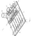
- FIG. 1illustrates one embodiment of a microfluidic chip of the invention.
- FIG. 2illustrates an alternative view of the microfluidic chip of FIG. 1 .
- FIGS. 3 a - billustrate a microfluidic valve used in the embodiment shown in FIG. 1 .
- FIGS. 4 a - 4 fillustrate a microfluidic pump used in the embodiment shown in FIG. 1 .
- FIGS. 5 a - cillustrate an inlet valve used in the embodiment shown in FIG. 1 .
- FIGS. 6 a - billustrate a cartridge and a reservoir used in the embodiment shown in FIG. 1 .
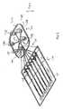
- FIG. 7shows an assay chip having ducts that connect to a separate reagent chip.
- FIGS. 8-10illustrate steps for manufacturing the device of FIG. 7 .
- FIGS. 11 a - cillustrate an exemplary insert sized and shaped to inter-fit within the embodiment shown in FIG. 1 .
- FIG. 12illustrates an embodiment of a chip in which a single driving force distributes a reagent to a plurality of outlet reservoirs.
- FIG. 13illustrates an embodiment of a chip in which multiple driving forces distribute a reagent to a plurality of outlet reservoirs.
- FIG. 14illustrates an embodiment of a chip having multiple driving forces distributing a plurality of reagents to a plurality of outlet reservoirs.
- FIGS. 15 a - cillustrate a method of inter-fitting the exemplary insert of FIGS. 11 a - c within a channel of the embodiment shown in FIG. 1 .
- FIGS. 16 a - bshow the results of a microfluidic-based on-chip immunoassay process.
- FIG. 17illustrates steps in identifying samples containing a target analyte.
- FIG. 18shows a complete and self-contained microfluidic system including a computer, a controller and a chip.
- FIG. 19illustrates an alternate embodiment of a chip coupled to a controller.
- FIG. 1illustrates a microfluidic system 1 that includes an assay chip 5 and a cartridge 10 disposed on the chip 5 along a width of the chip 5 .
- the cartridge 10includes a plurality of reagent reservoirs 12 having side walls that define chambers to hold fluid reagents.
- the chip 5includes a buffer reservoir 16 having a cylindrical sidewall to hold a washing buffer, a plurality of shuttle reservoirs 17 adapted to hold reagents during an assay operation, and a waste reservoir 18 adapted to hold used reagents and used buffer after the assay operation.
- the chip 5also includes a plurality of inlet valves 14 positioned to align with the various reservoirs. The inlet valves 14 serve to control fluid flows between the reservoirs and respective microchannels in the chip 5 .
- the chip 5includes a plurality of inlet channels 20 , a distribution valve 25 , an inlet 30 , a waste channel 38 , a plurality of reagent and or buffer outlet channels 35 , assay channels 40 , fluid pumps 44 , and outlet reservoirs 48 .
- the distribution valve 25controls the release of fluid from the inlet channels 20 to the inlet 30 .
- the distribution valve 25controls the release of fluid from the inlet 30 to the waste channel 38 .
- the inlet 30serves as an inlet to outlet channels 35 which are in fluidic communication with the assay channels 40 .
- the pumps 44pump fluid in a direction 60 towards the outlet reservoirs 48 , but can also be programmed to pump fluid generally in the direction 62 towards the shuttle reservoirs 17 and the inlet 30 .
- the chip 5is generally constructed from a first substrate 6 , a second substrate 7 , and a membrane 8 (not shown) disposed in between the two substrates 6 and 7 .
- the membrane 8has a thickness of between about 10 ⁇ m and about 150 ⁇ m, or between about 15 ⁇ m and about 75 ⁇ m.
- the depicted first substrate 6 and second substrate 7each has a thickness substantially larger than the thickness of the membrane 8 , but in other implementations, has a thickness similar to or less than the thickness of the membrane 8 .
- the microfluidic channels 20 , 25 , 38 , and 40may be of any suitable dimension, but in certain embodiments have cross-sectional dimensions of between about 1 ⁇ m and about 500 ⁇ m, or between about 1 ⁇ m and about 50 ⁇ m.
- the first substrate 6 , the second substrate 7 , and the membrane 8are all made of plastic.
- Exemplary materialsinclude non-elastomeric polymers, such as polymethyl methacrylate, polystyrene, polycarbonate, and acrylic. These materials are beneficial at least in part because they are reasonably rigid, which is suitable for the first substrate 6 and the second substrate 7 . Moreover, these materials can be deformable when used in thin layers, which is suitable for the membrane 8 which may deflect towards and away from the first 6 and second 7 substrates.
- the system 1provides automated “many-to-many” reagent dispensing and processing.
- inlet valves 14By selectively operating inlet valves 14 , distribution valve 25 and fluid pumps 44 , various combinations of fluid flow patterns among reagent reservoirs 12 , buffer reservoir 16 , waste reservoir 18 , shuttle reservoirs 17 and outlet reservoirs 48 can be achieved.
- the distribution valve 25may be constructed in accordance with the valve structure described with respect to FIGS. 3 a - b .
- FIGS. 3 a - bshow a three-layer active planar valve structure 399 , which may be formed using acetonitrile assisted bonding.
- the valve structure 399includes a first substrate 300 having interdisposed microchannels 301 and 303 .
- a membrane layer 304is selectively bonded to the first substrate 300 in areas 306 , thus creating a diaphragm structure 308 .
- a second substrate 302is bonded to the membrane 304 .
- the second substrateincludes a drive chamber 310
- the channel pumps 44 of FIG. 1may be constructed in accordance with the pump structure described with respect to FIG. 4 a - f .
- a microfluidic pumpgenerally refers to any structure or group of structures capable of applying positive and/or negative pressure to a fluid and/or facilitating the flow of fluid in one or more desired directions.
- the depicted micro-diaphragm pump 400generally includes three valves: an inlet valve 402 , a drive valve 404 and an outlet valve 406 , interconnected by portions 418 b and 418 c of microchannel 418 .
- the pump 400pumps fluid through the microfluidic channel 418 by cycling through six states that are activated sequentially to produce a peristaltic-like pumping effect.
- FIG. 4depicts three valve structures 402 , 404 and 406 that make up the pump 400
- other pump embodimentsmay contain four or more valve structures.
- the inlet valve 402opens and draws fluid from an inlet portion 418 a of the microfluidic channel 418 into volume 425 between the membrane 408 and the second substrate 432 .
- the drive valve 404opens and draws more fluid into the pump system.
- the inlet valve 402closes.
- the outlet valve 406opens.
- the drive valve 404closes, and thereby forces fluid through the outlet valve 406 and into an outlet portion 418 d of the microfluidic channel.
- the outlet valve 406then closes.
- the pump 400is bidirectional. If the cycle is reversed, portion 418 d is an inlet portion of the microfluidic channel 418 , portion 418 a is an outlet portion of the microfluidic channel 418 , and fluid flows from portion 418 d to portion 418 a.
- valve structures 402 , 404 , and 408are independently actuatable, in that any one of the valve structures can be actuated with little or substantially no effect on the state of the other valve structures.
- Those skilled in the artwill recognize that alternate sequences of states may produce a pumping effect, and that other pumps can also be used with this invention.
- FIGS. 5 a - billustrate an exemplary inlet valve structure 14 of FIG. 1 .
- the valve 14includes a first substrate 508 with a drive chamber 510 fabricated therein, a second substrate 515 and a membrane 520 .
- a reservoirmay be disposed above the second substrate 515 and aligned with reservoir port 540 to provide a source of fluid for porting into channel 545 .
- the reservoirswill be discussed in detail with respect to FIGS. 6 a - b .
- FIG. 5 cillustrates an exemplary structure including a plurality of inlet valves 14 of FIG. 1 connected in series.
- valve structures of this inventionmay be connected in series by microchannels to form a pump that operates with a peristaltic-like mechanism, such as the pumps 44 of FIG. 1 .
- Other arrangements of valve structures interconnected by microchannelscan also form generic pumping configurations.
- FIG. 6 ashows a cartridge 610 with a top side 602 and a bottom side 604 having a reagent reservoir 612 formed thereon.
- the cartridge 610is provided with its top side 602 and bottom side 604 both sealed by suitable adhesive materials.
- the top adhesive material 605is a sealing tape
- the bottom sealing materialmay also be a sealing tape.
- Other suitable adhesive materialsmay also be used.
- FIG. 6 adepicts the cartridge 610 having only the reagent reservoirs 612 disposed thereon, although various other cartridge configurations are possible.
- a cartridgeincludes a buffer reservoir 616 , a waste reservoir 618 and a plurality of shuttle reservoirs 617 in addition to the reagent reservoirs 612 .
- a cartridgeincludes the reagent 612 and buffer 616 reservoirs.
- the shuttle 617 and waste 618 reservoirsmay be integrally constructed onto the chip 615 or provided on a separate cartridge.
- three separate cartridgesare provided respectively including the shuttle reservoirs 617 , the reagent reservoirs 612 , and the buffer 616 and waste 618 reservoirs.
- a cartridgehas only the shuttle reservoirs 617 for distributing different reagents to assay channels 630 - 635 .
- FIGS. 7-10illustrate an alternate method for coupling multiple reservoirs to an assay chip.
- FIG. 7shows an assay chip 705 , a reagent chip 710 , and a ducting chip 715 .
- the reagent chip 710includes a reagent cartridge 720 and a reagent loading chip 725 .
- the ducting chip 715serves to provide bi-directional fluid flows between the reagent chip 710 and the assay chip 705 .
- the reagent chip 710allows several reagent reservoirs 735 - 739 to dispense reagents into reservoir 740 before being ported to the assay chip 705 through the ducting chip 715 .
- one of the reagent reservoirs 735 - 739may be a buffer reservoir for storing a buffer solution. In certain arrangements, one of the reservoirs 735 - 739 may be a waste reservoir for storing used reagents after an assay.
- the ducting chip 715is rigid enough to provide the necessary structural support to duct the assay chip 705 to the reagent chip 710 .
- the ducting chip 715is deformable such that reagent chip 710 and assay chip 705 need not be exactly aligned along a vertical axis 750 when they are attached by the ducting chip 715 .
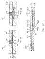
- the ducting chip 800includes a cover layer 805 for being generally disposed over a portion of the channels 730 , as shown in FIG. 7 .
- the ducting chipfurther includes a first support layer 810 , a channel layer 815 , and a second support layer 820 .
- Layers 805 and 810are provided with apertures 825 that are aligned to allow fluid to flow from channels 830 in a downward 832 direction.
- the channel layerincludes a plurality of inter-disposed channels 830 .
- the first support layer 810 , the channel layer 815 , and the second support layer 820include apertures 845 that are substantially aligned to allow fluid to flow in a downward 832 direction from a reservoir 840 .
- An adhesive O-ring 835adheres the reservoir 840 to the second support layer 820 .
- the layersmay be adjoined with the lamination methods described herein.
- FIG. 8 bshows the ducting chip 800 of FIG. 8 a after assembly.
- the reagent loading chip 925includes a bottom substrate layer 905 with drive chambers 907 , a membrane layer 910 , and a top substrate layer 915 with microchannels etched therein. The layers may be attached with suitable lamination methods described herein.
- FIG. 9 bshows a top view of the reagent loading chip 925 .
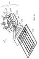
- FIG. 10illustrates an exploded view of the full structure including the ducting chip 1015 , the reagent loading chip 1025 , the reagent cartridge 1020 , and the assay chip 1005 .
- FIG. 10shows the reagent cartridge 1020 being laminated to the reagent loading chip 1025 , the ducting chip 1015 being coupled to the reagent loading chip 1025 , and the assay chip 1005 being attached to the ducting chip 1015 .
- FIGS. 1 and 10Various alternative arrangements may be applied to the microfluidic systems 1 and 1000 of FIGS. 1 and 10 , respectively.
- a plurality of void regions 1060 - 1065may be disposed in the respective assay channels.
- These void regions 1060 - 1065may be open to a top surface of the chip 1005 .
- a cover adhesive layermay be disposed over each channel void region 1060 - 1065 .
- a temperature-modulating devicesuch as a heater or a cooler, may be coupled to the microfluidic systems 1 and 1000 to regulate the temperature of the fluids in the systems for providing an optimal environment wherein on-chip biological and/or chemical reactions may occur.
- reagent reservoirs 12there are six shuttle reservoirs 17 , six outlet reservoirs 48 , one waste reservoir 18 and one buffer reservoir 16 .
- reagent reservoirs 1035 - 1039there are six reagent reservoirs 1035 - 1039 , any of which may be a buffer or waste reservoir.
- various other combinations of reagent, shuttle, outlet, waste and buffer reservoirsare possible.
- the assay channelsmay be provided with biological or chemical materials that react with reagents introduced into the microfluidic system.
- insertsare provided with chemical and/or biological agents for insertion into the microchannels for the purpose of reacting with the reagents. Exemplary inserts are shown in FIGS. 11 a - b .
- the insertis a flexible plastic strip with an adhesive coating on one side.
- the insertis a thin polystyrene strip.
- the inserthas a thickness of between about 50 microns to about 500 microns in thickness, a width of between about 1 mm to about 5 mm, and a length of between about 5 mm to about 100 mm.
- the assay channelsare configured accordingly in order to accommodate the inserts disposed therein.
- an insertmay be provided with chemical and/or biological agents.
- an insertincludes a membrane 1104 having adhesive disposed on its surface and membrane disks 1110 adhered to the membrane 1104 , wherein the membrane disks 1110 are provided with chemical and/or biological agents.
- the membrane 1104is further provided with apertures 1115 over which the membrane disks 1110 lie.
- the apertures 1115may be included in a perforated cover strip 1105 adhering to the membrane 1104 .
- the aperturesserve to allow fluid contact between the bottom side of the membrane disks 1110 and a fluid flow through channel 1130 wherein the insert 1107 is disposed.
- the apertures 1115are circular. In one example as shown in FIG.
- the apertures 1115each includes a central circular region 1120 with two opposing rectangular regions 1122 open to the circular region 1120 .
- the rectangular regions 122are oriented on the insert 1107 in a direction 1132 aligned with a direction of fluid flow when the insert 1107 is disposed in the assay channel 1130 . This feature enables the insert 1107 to trap air bubbles in the fluid.
- the membrane disks 1110are preferred to be circular, although other shapes are possible.
- the apertures 1115are shaped and sized to provide structural support for the membrane disks 1110 . For the case of circular disks and circular apertures as illustrated in FIG.
- the disks 1110are preferred to have a diameter of between about 1 mm and about 5 mm, and the apertures 1115 are preferred to have a diameter that is between about 5% and about 10% less than the diameter of the disks 1110 .
- a diameter of the central circular regions 1120 of the apertures 115may be between about 5% and about 10% less than a major diameter of the membrane disks 1110 .
- a width 1124 of the rectangular regions 1122may be between about 5% to about 10% less than the diameter of the central circular regions 1120 .
- the membrane disks 1110may be made of a porous material such as nitrocellulose.
- the porosity of the membrane disks 1110may be sufficiently large to allow fluid and salt passing through but small enough to interact with macromolecules, viruses or bacteria in the fluid.
- the membrane disks 1110may be made of nitrocellulose, PVDF and/or nylon, which are suitable materials for use in a microfluidic-based dot-chip process as will be described below.
- the membrane disks 1110 and the apertures 1115may be formed by, for example, a die cut or laser cut. The operations of various components of the microfluidic system 1 of FIG. 1 will be described below. By selectively operating the inlet valves 14 , distribution valve 25 , and channel pumps 44 , various combinations of fluid flow patterns might be achieved.
- one or more reagents stored in reagent reservoirs 12 and/or washing buffer in buffer reservoir 16may be selectively dispensed into assay channels 40 at appropriate rates, amounts and temperatures, incubated in the channels 40 and disposed through waste reservoir 18 via outlet reservoirs 48 and shuttle reservoirs 17 . Exemplary application of these operations will be discussed herein.
- FIGS. 3 a - billustrate one method for operating the distribution valve 25 of FIG. 1 .
- a positive upward pressureis applied to the diaphragm 308 via the drive chamber 310 , the membrane 308 is pushed away against the valve seat 312 between the two microfeatures 301 and 303 , effectively preventing any transfer of fluid between them.
- a negative downward pressureis applied to the drive chamber 310 , the membrane 308 is pulled away from the valve seat 312 and the fluid is free to communicate between the microfeatures 301 and 303 via void region 314 .
- Pressuremay be applied through the drive chamber 310 pneumatically or by physically contacting the membrane through the drive chamber 310 .
- FIGS. 4 a - fillustrate one method for pumping fluid through the pump structure 44 of FIG. 1 .
- the methodcomprises cycling the pump structure though six states that are activated sequentially to produce a pumping effect.
- the inlet valve 402is opened and fluid is drawn from inlet microchannel 412 into the volume 402 a between the membrane 408 and the first substrate 410 .
- the drive valve 404is opened, drawing more fluid into the pump system.
- the inlet valve 402is closed.
- the outlet valve 406is opened.
- the drive valve 404is closed, forcing fluid out through the outlet valve 406 into outlet microchannel 418 .
- microchannel 418serves as an inlet microchannel
- microchannel 412serves as an outlet microchannel
- fluidmay be drawn from inlet microchannel 418 to outlet microchannel 412 .
- FIGS. 5 a - billustrate one method for operating the inlet valves 14 of FIG. 1 .
- a positive pneumatic force 525is applied through drive chamber 510 , forcing the valve 500 to be in a closed position wherein there is no fluidic communication between inlet channel 545 and reservoir port 540 .
- a negative pneumatic force 530is applied through drive chamber 510 , forcing the valve 500 to be in an open position wherein reservoir port 540 is in fluidic communication with inlet channel 545 .
- FIG. 5 cillustrates the operation of a plurality of inlet valves being connected in series.
- communication between inlet valves 550 and 557may be controlled by actuating a valve structure 565 connected to the inlet valves.
- a positive pneumatic force 570may be applied through the drive chamber 586 disposed in the bottom substrate 593 . This force will push the membrane 588 into conformal contact with a region 590 of the top substrate 592 .
- the valveis in a closed position with substantially no fluidic communication between adjoining microchannels 572 and 573 .
- a negative pneumatic force 575 applied through the drive chamber 586will pull the membrane 588 away from the top substrate 592 , such that the membrane 588 forms a cavity towards the drive chamber 586 into the region 587 .
- the valveis in an open position in which adjoining microchannels 572 and 573 are in fluidic communication.
- a userturns the cartridge 610 such that its bottom side 604 is facing up, removes the bottom sealing backing, aligns the cartridge 610 to the assay chip 615 such that the reagent reservoirs 612 are aligned with respective valves 614 , and then presses the assay chip 615 against the cartridge 610 .
- reagent cartridgeis held together with the assay chip 615 , reagent 620 within the respective reagent reservoir 612 is maintained within the reagent reservoir 612 by a hydrophobic property of the surface of aperture 624 .
- the chip assemblymay be placed on a controller (not shown) and the cover sealing tape is removed to release the reagent 610 onto the assay chip 615 by actuating corresponding valves and pumps described below.
- FIGS. 12-14illustrate various embodiments for distributing fluids through the chip 1 of FIG. 1 by actuating the pump and valve structures described above.
- FIG. 12illustrates a single driving force for distributing a reagent from a reagent reservoir 1205 a among a plurality of microchannels 1220 - 1223 on a chip 1200 .
- the single driving forceis produced by an inlet valve 1215 a and a drive diaphragm 1224 located in between the area of an inlet valve 1215 a and an outlet valve 1225 .
- These three valvesmay operate according to the peristaltic-like pumping mechanism described above with respect to FIG. 4 to transport fluid contents of reservoir 1205 a among the outlet channels 1210 - 1213 .
- reagent contents of reservoirs 1205 b - dmay be delivered to outlet channels 1210 - 1213 via pumping action produced by respective ones of inlet valves 1215 b - d , drive diaphragm 1224 and outlet valve 1225 . This results in a “many-to-many” functionality wherein several reagents are being distributed to several outlet reservoirs.
- outlet channels 1210 - 1213impact the fluid flow rate on assay channels 1220 - 1223 .
- the flow rate in each channel of an assay chipis inversely proportional to the flow resistance of that channel.
- the outlet channels 1210 - 1213may be fabricated to have different flow resistances if an application calls for different channels to have different respective flow rates.
- the sensitivity of flow rates to channel resistanceis a detriment to reagent processing if the varying resistances among channels is unintentional.
- air bubbles formed during assaymay result in varying flow resistances which cause an uneven distribution of reagent across the assay channels 1220 - 1223 .
- FIG. 13illustrates an embodiment of the chip 1 in FIG. 1 that overcomes the variation in flow rates resulting from varying channel flow resistances.
- Each assay channel 1310 - 1315 and each outlet channel 1360 - 1365are associated with a respective fluid pump 1320 - 1325 .
- the amount of fluid delivered to the channel by each of the pumps 1320 - 1325is relatively unaffected by variations in flow resistance among the assay channels 1310 - 1315 when the flow resistance is substantially smaller than the pneumatic driving force used to operate the fluid pumps 1320 - 1325 .
- the channel-to-channel flow rate variationis dominated by the characteristics of pumps 1320 - 1325 rather than channel flow resistances.
- FIG. 13illustrates a reagent from reagent reservoir 1350 being distributed (see arrows) among outlet channels 1360 - 1365 via distribution valve 1352 .
- a plurality of reagents from their respective reagent reservoirs 1350 - 1355are delivered to the distribution valve 1352 wherein the reagents may be mixed to create a reagent mixture.
- the reagent or reagent mixturemay be further distributed to selected assay channels 1310 - 1315 , outlet reservoirs 1330 - 1335 , and/or shuttle reservoirs 1340 - 1345 .
- FIG. 14illustrates additional fluid distribution patterns of the microfluidic system shown in FIG. 1 .
- each shuttle reservoir 1440 - 1445 , assay channel 1410 - 1415 and outlet channel 1460 - 1462are connected in series to form a fluid pump 1420 - 1425 , wherein each fluid pump 1420 - 1425 provides bi-directional fluid flow to and from the respective micro-features.
- fluid pumps 1420 - 1425provides bi-directional fluid flow between shuttle reservoirs 1440 - 1445 and outlet reservoirs 1430 - 1435 interconnected by the respective assay channels 1410 - 1415 .
- a reagent in outlet reservoir 1432is delivered through outlet channel 1461 and distribution valve 1462 to waste reservoir 1464 .
- a reagent in shuttle reservoir 1443is delivered to waste reservoir 1464 via outlet channel 1461 and distribution valve 1462 .
- different reagents or reagents of different concentrationsmay be introduced to the assay channels 1410 - 1415 from the corresponding shuttle reservoirs 1440 - 1445 . Introducing reagents from shuttle reservoirs permits variability in assay channel conditions through tailored reagent delivery.
- the pumps and valves of FIG. 1may be selectively and programmably actuated.
- a usermay release selected reagents stored in selected reagent reservoirs 12 and/or washing buffer stored in buffer reservoir 16 .
- channel pumps 44By selectively actuating channel pumps 44 , a user may store these fluids in selected shuttle reservoirs 17 and outlet reservoirs 48 , release these fluids stored in the selected shuttle reservoirs 17 and outlet reservoirs 48 , and store these fluids in waste reservoir 18 .
- a useris able to perform any desired combination of incubation/mixing/reacting/aspiration of the fluids in the reagent 12 and buffer 16 reservoirs.
- the microfluidic system 1000 of FIG. 10separates the assay functionality of the invention from the reagent delivery functionality. In situations where a particular assay needs to be performed repeatedly, it may be more inconvenient to use a larger cartridge repeatedly than several smaller ones.
- the microfluidic system 1000may be used to run a number of identical assays in parallel.
- the reagent reservoirs 1035 - 1039are provided with enough reagents to run several assays, and the reagent chip 1010 supplies reagent to several chips as their respective assays are being performed.
- ducting chip 1015may be used to duct used reagents from assay chip 1005 into reservoir 1040 on reagent chip 1005 .
- the used reagent in reservoir 1040is then ported to waste reservoir 1035 for disposal. Waste reservoir 1035 may be utilized to store used reagents from one or more assay chips.
- the microfluidic system 1000operates by flowing fluids from reagent reservoirs 1035 - 1039 into reservoir 1040 .
- a fluidmay be delivered from reservoir 1037 to reservoir 1040 via valve 1041 much like the process shown in FIG. 5 c according to which a fluid from valve 550 is delivered toward valve 555 via valve 565 .
- actuating valve 1050delivers fluid into channel 1072
- actuating valve 1041delivers fluid into channel 1073
- actuating valve 1055delivers fluid into reservoir 1040 .
- a fluidflows from reservoir 1040 into a reagent reservoir 1036 by a similar mechanism as that illustrated in FIG. 5 c .
- valves 1055 , 1041 and 1062all in open states, actuating valve 1055 pushes fluid into channel 1073 , actuating valve 1041 pushes fluid into channel 1064 , and actuating valve 1062 pushes fluid into reservoir 1035 .
- the insert 1107is first deposited into an assay channel 1130 through an opening of the outlet reservoir 1134 that is located at the end of the assay channel 1130 and has a width substantially the same as the width of the assay channel 1130 .
- the insert 1107is slid into the channel 1130 until it spans a length 1136 of the channel.
- the insertis inserted into the assay channel 760 through channel void 730 .
- the channel void 730is provided with an open top in which the insert is disposed.
- the insertis slid into the channel 730 until it spans a length 762 of the covered portion of the channel 760 .
- an adhesive covermay be placed over the channel void region 730 to form shuttle reservoirs at the end of the assay channel 760 .
- FIG. 15 aillustrates the insertion of an insert 1507 , and in particular, shows an exemplary channel structure that facilitates the use of the insert 1507 .
- the channel 1520is a stepped channel including a wide bottom portion 1522 and a narrow top portion 1524 .
- the insert 2017is inserted into the stepped channel 1520 such that it generally overlies membrane 1510 , as shown in FIG. 15 c .
- FIG. 15 cshows the insert 1507 having an aperture 1515 and a membrane disk 1525 .
- the insert 1507is situated in the channel 1520 such that the top surface of the membrane disk 1525 does not contact a top surface 1517 of the channel 1520 , allowing for fluid in channel 1520 to flow around and contact the membrane disk 1525 .
- the insertis used to perform an assay similar in principle and function to a dot-ELISA method.
- the dot-ELISAis a method, known in the art, for detecting the presence of a target analyte within samples.
- Drawbacks of the conventional dot-ELISA processinclude difficulties with standardization. Many of the steps are often performed by hand in Petri dishes and the specification of these procedures is vague. Additionally, sample locations are hardly controllable. When sample is spotted on a membrane surface, the hydrophilicity of the material may lead to rapid sample spreading and diffusion. Larger sample amounts result in larger spotted areas. Moreover, since detection sensitivity is related to analyte density per unit area, this diffusion means that larger sample amounts do not necessarily result in lower detection limitation.
- the present inventionemploys a similar assay processing, but allows for standardized and more efficient handling, treatment, and analysis.
- samplesare applied to a membrane disk 1110 as shown in FIGS. 11 a - b .
- the samplesare air dried, and then the insert 1105 is disposed in an assay channel of a microfluidic chip, similar to that of FIG. 1 .
- reagent reservoirs 12for conducting on-chip immunoassay.
- the reagentsinclude fluids that will be employed in a dot-ELISA assay. More specifically, various reservoirs may include one or more of buffer washing buffer, antibody, antibody with conjugated enzyme, and enzyme substrate. In some cases, a buffer reservoir 16 may be used to store a washing buffer. The buffer reservoir 16 may feature a substantially larger void volume than the individual reagent reservoir 12 .
- the reagentsare released from their respective reservoirs 12 by activating respective inlet valves 14 and then distributing the reagents throughout the assay channels 40 using the activation of distribution valve 25 and channel pumps 44 .
- the washing buffer in buffer reservoir 16may also be released into the assay channels 40 in a similar manner.
- the order and timing of release of the reagents and buffer from their respective reservoirswill correspond to the steps of the assay method used.
- the reagentsmay correspond to the reagents described above with respect to the immunoassay process, and are released in accordance with the order and timing of the steps mentioned above.
- the released reagentsflow through the assay channels 40 and contact the inserts 70 therein. With respect to FIG.
- Apertures 1515provide for the possibility of additional fluid contact along a bottom side of the membrane disks 1525 .
- the channelsmay be provided with materials with which the fluid reagents react, i.e., reagents may flow through assay channels with membrane disks disposed therein, thereby causing the occurrence of interactions between the reagents and the analysts on the membrane disks. It may be desirable to allow dynamic flow conditions or longer incubation times for the reactions via multiple passes of the reaction reagent through channels. This is achieved in part by the bidirectional pumping functionality of this invention.
- the bidirectional channel pumps 44are used to repeatedly shuttle a reagent back and forth between the shuttle reservoirs 17 and outlet reservoirs 48 along respective assay channels 40 . This cycling action provides multiple passes for much greater efficiency at longer reaction time.
- the outlet reservoirs 48 and shuttle reservoirs 17are directly vented to the atmosphere, thereby allowing release of air from the channels 40 during the pumping cycles.
- the void volume of each shuttle reservoir 17 and each outlet reservoir 48are substantially larger than the void volume of each assay channel 40 so that reagents in the channels 40 may be stored in the reservoirs during the back and forth pumping action. After the assay operation, used reagents are then transported to the waste reservoir 18 for disposal.
- the void volume of waste reservoir 18is substantially larger than the void volume of the buffer reservoir 16 for storing all used reagents and washing buffer after an assay operation. After the inserts are treated with different reagents, the color of the membrane disks may be observed for the presence of a target analyte in the samples.
- sample spotting onto the insert 1107is accomplished by placing the insert 1107 on an absorbent backing material such as a chromatograph paper with membrane disk surface touching the paper.
- an absorbent backing materialsuch as a chromatograph paper with membrane disk surface touching the paper.
- the sample droplet diffusion areais substantially defined by the area of the membrane disk 1110 .
- the membrane disks 1110may be placed closer together than the sample spots 2210 would be placed on the monolithic membrane 2205 as shown in FIG. 22 , thus resulting in improved space efficiency for on-chip processing and potential reagent savings.
- membrane disks 1110at predefined and well known locations along the insert 1107 , with embedded barcodes or other identifiers on-chip, facilitates the use of the assay chip in automated data processing and image analysis methods that make data archiving for on-chip immunoassay results much more useful.
- FIG. 16 aillustrates a plurality of inserts 1705 in channels after an assay has been performed.
- certain membrane disks 1710 ahave been colored as positive results by an enzyme-substrate reaction, indicating the presence of a target analyte in a sample disposed on the corresponding membrane disk.
- Other membrane disks 1710 bare substantially not colored, indicating no target analyte in a sample disposed on the corresponding membrane disk.
- each insert 1705includes eight membrane disks 1710 .
- Each chipmay include six or more assay channels, and therefore at least 48 samples may be assayed simultaneously.
- an image analysis methodfor the automated processing of on-chip immunoassay results.
- a microfluidic chipmay be scanned utilizing, for example, a photo scanner or a digital camera to capture one or more colored images of the inserts after an assay operation.
- FIG. 16 aprovides an exemplary image of an 8 ⁇ 6 sample-spotted array.
- the scanned imagesmay be stored in a handheld device for further off-line manipulation or sent to a remote computer for off-line image analysis.
- Image analysis softwaremay then be used to analyze the color intensities of the membrane disks from the captured color images. The intensity of each membrane disk 1710 is subsequently digitized into pixels with a numerical value assigned to each pixel.
- FIG. 16 billustrates an exemplary array of color intensity values 1716 corresponding to the membrane disk array shown in FIG. 16 a.
- each membrane disk 1710 in a sample arrayis uniquely identifiable by a combination of a barcode embedded in the chip and a set of coordinates specifying the channel and insert positions at which a membrane disk is located.
- a membrane disk 1710 c on the upper-left corner of a chip that is bar-coded as CHIP-0001may be labeled as CHIP-0001-A1, where A1 indicates a combination of the column 1712 and row 1714 positions where the disk 1710 c lies.
- placing the membrane disks 1710 at predefined locations on a bar-coded chipenables their corresponding color intensity values 1716 to be easily archived in a database for future reference.
- a protocolfor interpreting a color intensity value 1716 for identifying the presence of a target analyte in a sample disposed on the corresponding membrane disk 1710 .
- a threshold valueis computed using negative control disks such that a color intensity value 1716 is interpreted as having a positive result for target analyte if the color intensity value is above the threshold value.
- FIG. 17provides an illustration for determining the presence of a target analyte in eight exemplary samples. These samples are disposed on membrane disks 1814 and correspond to computed color intensity values 1812 .
- the threshold value 1810 in this particular embodimentis 26.8 by arithmetically averaging C 1 , F 1 , B 2 , E 2 , H 2 , C 3 , F 3 , B 5 , E 5 and H 5 as shown in FIG. 16 b .
- the membrane disks 1814 in positions A, B, D, E, G, Hare identified as having coated with the target analyte-containing solution. This automated identification procedure reduces human reading errors, especially when interpreting samples, such as that in position F, where the corresponding color intensity 1814 a is fairly close to the threshold value 1810 .
- the samples and target analytes for the assaymay be any samples and targets suitable for use with immunoassay processes.
- the samplesmay include control samples and experimental samples.
- Experimental samplesare generally taken from a subject with a condition of interest, and control samples generally mimic the subject but exclude the analyst of interest.
- experimental samplesare taken from a potentially diseased patient.
- a subjectmay be, for example, a human, animal or plant.
- FIG. 18shows a complete system including an assay chip 1905 , a cartridge 1910 , a controller 1915 , and a computer 1920 .
- the controller 1915allows for automated control of the various pump and valve structures of the chip 1905 .
- the chip 1905includes pneumatic drivers 1920 (not shown) positioned to be substantially aligned with the pump and valve structures of the chip 1905 . Positive or negative pneumatic pressure is applied via the drivers 1920 in accordance with input signals provided through input wires 1925 .
- the computer 1920may provide a user interface for controlling the controller 1915 .
- a usermay provide inputs specifying requirements on a particular assay run using a graphical user input provided by the computer 1920 .
- the computeris electrically connected to the controller 1915 and provides signals to the controller 1915 so it acts in accordance with the user inputs.
- FIG. 19illustrates an embodiment with an assay chip 2005 ducted to a separate reagent chip 2010 on a programmable controller 2015 .
- the controller 2015includes a group of pneumatic solenoid valves. Each of the pneumatic signals from the solenoid valves is routed through the chip to one or a series of microfluidic valves on a specific chip layout. For example, in one embodiment there is an individual solenoid valve connected to each of the corresponding reagent reservoirs 12 of FIG. 1 , but all six of the channel pumps 44 are connected in parallel to a set of four solenoid valves so they may act together. There is a solenoid drive board in the controller 2015 that takes the signals from the computer and turns on the appropriate solenoid valve to actuate the required microfluidic valve.
- the microprocessor on the control boardincludes a memory which may store the sequence and thus an assay may be run independently of external computer control.
- the microfluidic chip of the inventiongenerally includes a top substrate 7 , a bottom substrate 6 , and a membrane 8 disposed therebetween.
- the microfeaturese.g., pumps, valves, or reservoirs
- the top substrate 7 and the membrane 8are laminated together, and similarly the membrane 8 and the bottom substrate 6 are laminated together. While any lamination method known in the art may be used, in one aspect of the invention these layers are laminated by: 1) using a weak solvent bonding agent, and 2) laminating the layers under mild conditions, such as under low heat or low pressure.
- the weak solvent bonding agentis applied to one or both surfaces to be adhered, and then mild pressure (e.g., from moderate heat or moderate physical pressure pressing the surfaces together) adheres the surfaces.
- the weak solvent bonding agentmay be chemically defined as:
- the weak solventmay have a chemical formula of:
- the weak solventmay have a chemical formula of:
- the weak solvent bonding agentis acetonitrile.
- Acetonitrileis a versatile solvent that is widely used in analytical chemistry and other applications. It is 100% miscible with water and exhibits excellent optical properties. The ability of acetonitrile to have little or no effect on polymeric surfaces under ambient conditions but adhere, the surfaces under moderate pressure makes it highly suitable for laminating polymeric materials such as polystyrene, polycarbonate, acrylic and other linear polymers. For example, microstructures disposed on a polystyrene substrate that was treated with acetonitrile at room temperature for at least several minutes did not exhibit any noticeable feature damage.
- acetonitrile-based laminationallows substrate alignment for structures containing multi-component layers or fluid networks constructed utilizing both a cover plate and a base plate.
- acetonitrile at room temperaturemay gently soften the surface.
- an operatormay slide the two surfaces against each other to adjust their alignment. After aligning the surfaces, the operator may then apply pressure to the surfaces to laminate them together.
Landscapes
- Chemical & Material Sciences (AREA)
- Engineering & Computer Science (AREA)
- Health & Medical Sciences (AREA)
- General Engineering & Computer Science (AREA)
- Dispersion Chemistry (AREA)
- Mechanical Engineering (AREA)
- Chemical Kinetics & Catalysis (AREA)
- General Health & Medical Sciences (AREA)
- Analytical Chemistry (AREA)
- Clinical Laboratory Science (AREA)
- Hematology (AREA)
- Computer Hardware Design (AREA)
- Microelectronics & Electronic Packaging (AREA)
- General Physics & Mathematics (AREA)
- Immunology (AREA)
- Pathology (AREA)
- Biochemistry (AREA)
- Life Sciences & Earth Sciences (AREA)
- Physics & Mathematics (AREA)
- Automatic Analysis And Handling Materials Therefor (AREA)
- Physical Or Chemical Processes And Apparatus (AREA)
Abstract
Description

where, R1=H, OH or R, where R=alkyl, or is absent, R2=H, OH or R, where R=alkyl, or is absent, and R2=H, OH or R, where R=alkyl, or is absent.


Claims (20)
Priority Applications (6)
| Application Number | Priority Date | Filing Date | Title |
|---|---|---|---|
| US11/650,006US7959875B2 (en) | 2006-01-19 | 2007-01-05 | Microfluidic chips and assay systems |
| US13/111,137US8372355B2 (en) | 2006-01-19 | 2011-05-19 | Microfluidic chips and assay systems |
| US13/189,787US8323586B2 (en) | 2006-01-19 | 2011-07-25 | Microfluidic chips and assay systems |
| US13/759,131US8778280B2 (en) | 2006-01-19 | 2013-02-05 | Microfluidic chips and assay systems |
| US14/268,399US9134207B2 (en) | 2006-01-19 | 2014-05-02 | Microfluidic chips and assay systems |
| US14/798,719US9328381B2 (en) | 2004-10-13 | 2015-07-14 | Self-contained biological assay apparatus, methods, and applications |
Applications Claiming Priority (2)
| Application Number | Priority Date | Filing Date | Title |
|---|---|---|---|
| US76055206P | 2006-01-19 | 2006-01-19 | |
| US11/650,006US7959875B2 (en) | 2006-01-19 | 2007-01-05 | Microfluidic chips and assay systems |
Related Parent Applications (1)
| Application Number | Title | Priority Date | Filing Date |
|---|---|---|---|
| US13/111,137ContinuationUS8372355B2 (en) | 2006-01-19 | 2011-05-19 | Microfluidic chips and assay systems |
Related Child Applications (4)
| Application Number | Title | Priority Date | Filing Date |
|---|---|---|---|
| US13/111,137ContinuationUS8372355B2 (en) | 2006-01-19 | 2011-05-19 | Microfluidic chips and assay systems |
| US13/111,137DivisionUS8372355B2 (en) | 2006-01-19 | 2011-05-19 | Microfluidic chips and assay systems |
| US13/189,787ContinuationUS8323586B2 (en) | 2006-01-19 | 2011-07-25 | Microfluidic chips and assay systems |
| US14/268,399ContinuationUS9134207B2 (en) | 2006-01-19 | 2014-05-02 | Microfluidic chips and assay systems |
Publications (2)
| Publication Number | Publication Date |
|---|---|
| US20070166200A1 US20070166200A1 (en) | 2007-07-19 |
| US7959875B2true US7959875B2 (en) | 2011-06-14 |
Family
ID=38137391
Family Applications (8)
| Application Number | Title | Priority Date | Filing Date |
|---|---|---|---|
| US11/594,444Active2029-07-03US7976795B2 (en) | 2006-01-19 | 2006-11-08 | Microfluidic systems |
| US11/650,006Active2030-04-06US7959875B2 (en) | 2004-10-13 | 2007-01-05 | Microfluidic chips and assay systems |
| US13/111,137ActiveUS8372355B2 (en) | 2006-01-19 | 2011-05-19 | Microfluidic chips and assay systems |
| US13/152,881ActiveUS8101428B2 (en) | 2006-01-19 | 2011-06-03 | Microfluidic systems and control methods |
| US13/189,787Active2027-01-07US8323586B2 (en) | 2006-01-19 | 2011-07-25 | Microfluidic chips and assay systems |
| US13/759,131ActiveUS8778280B2 (en) | 2006-01-19 | 2013-02-05 | Microfluidic chips and assay systems |
| US14/103,008Expired - Fee RelatedUS9151701B2 (en) | 2006-01-19 | 2013-12-11 | Microfluidic systems |
| US14/268,399ActiveUS9134207B2 (en) | 2006-01-19 | 2014-05-02 | Microfluidic chips and assay systems |
Family Applications Before (1)
| Application Number | Title | Priority Date | Filing Date |
|---|---|---|---|
| US11/594,444Active2029-07-03US7976795B2 (en) | 2006-01-19 | 2006-11-08 | Microfluidic systems |
Family Applications After (6)
| Application Number | Title | Priority Date | Filing Date |
|---|---|---|---|
| US13/111,137ActiveUS8372355B2 (en) | 2006-01-19 | 2011-05-19 | Microfluidic chips and assay systems |
| US13/152,881ActiveUS8101428B2 (en) | 2006-01-19 | 2011-06-03 | Microfluidic systems and control methods |
| US13/189,787Active2027-01-07US8323586B2 (en) | 2006-01-19 | 2011-07-25 | Microfluidic chips and assay systems |
| US13/759,131ActiveUS8778280B2 (en) | 2006-01-19 | 2013-02-05 | Microfluidic chips and assay systems |
| US14/103,008Expired - Fee RelatedUS9151701B2 (en) | 2006-01-19 | 2013-12-11 | Microfluidic systems |
| US14/268,399ActiveUS9134207B2 (en) | 2006-01-19 | 2014-05-02 | Microfluidic chips and assay systems |
Country Status (6)
| Country | Link |
|---|---|
| US (8) | US7976795B2 (en) |
| EP (1) | EP1979097B1 (en) |
| JP (1) | JP5250425B2 (en) |
| KR (1) | KR20080085898A (en) |
| CN (1) | CN101495236B (en) |
| WO (1) | WO2007084425A2 (en) |
Cited By (38)
| Publication number | Priority date | Publication date | Assignee | Title |
|---|---|---|---|---|
| US20100303687A1 (en)* | 2009-06-02 | 2010-12-02 | Integenx Inc. | Fluidic devices with diaphragm valves |
| US20110005932A1 (en)* | 2009-06-05 | 2011-01-13 | Integenx Inc. | Universal sample preparation system and use in an integrated analysis system |
| US20110126911A1 (en)* | 2009-12-01 | 2011-06-02 | IntegenX Inc., a California Corporation | Composite Plastic Articles |
| US20110214745A1 (en)* | 2006-01-19 | 2011-09-08 | Rheonix, Inc. | Microfluidic chips and assay systems |
| USRE43122E1 (en) | 1999-11-26 | 2012-01-24 | The Governors Of The University Of Alberta | Apparatus and method for trapping bead based reagents within microfluidic analysis systems |
| US8431390B2 (en) | 2004-09-15 | 2013-04-30 | Integenx Inc. | Systems of sample processing having a macro-micro interface |
| US8476063B2 (en) | 2004-09-15 | 2013-07-02 | Integenx Inc. | Microfluidic devices |
| US8512538B2 (en) | 2010-05-28 | 2013-08-20 | Integenx Inc. | Capillary electrophoresis device |
| US8557518B2 (en) | 2007-02-05 | 2013-10-15 | Integenx Inc. | Microfluidic and nanofluidic devices, systems, and applications |
| US8672532B2 (en) | 2008-12-31 | 2014-03-18 | Integenx Inc. | Microfluidic methods |
| US8748165B2 (en) | 2008-01-22 | 2014-06-10 | Integenx Inc. | Methods for generating short tandem repeat (STR) profiles |
| US8763642B2 (en) | 2010-08-20 | 2014-07-01 | Integenx Inc. | Microfluidic devices with mechanically-sealed diaphragm valves |
| US9121058B2 (en) | 2010-08-20 | 2015-09-01 | Integenx Inc. | Linear valve arrays |
| US20170175722A1 (en)* | 2015-12-21 | 2017-06-22 | Funai Electric Co., Ltd. | Method and Apparatus for Metering and Vaporizing Fluids |
| US9777305B2 (en) | 2010-06-23 | 2017-10-03 | Iti Scotland Limited | Method for the assembly of a polynucleic acid sequence |
| USD800335S1 (en)* | 2016-07-13 | 2017-10-17 | Precision Nanosystems Inc. | Microfluidic chip |
| US9915671B2 (en) | 2008-12-23 | 2018-03-13 | C A Casyso Ag | Cartridge device for a measuring system for measuring viscoelastic characteristics of a sample liquid, a corresponding measuring system, and a corresponding method |
| US10191071B2 (en) | 2013-11-18 | 2019-01-29 | IntegenX, Inc. | Cartridges and instruments for sample analysis |
| US10208332B2 (en) | 2014-05-21 | 2019-02-19 | Integenx Inc. | Fluidic cartridge with valve mechanism |
| US10288633B2 (en) | 2015-06-26 | 2019-05-14 | Abbott Laboratories | Reaction vessel moving member for moving reaction vessels from a processing track to a rotating device in a diagnostic analyzer |
| USD849265S1 (en)* | 2017-04-21 | 2019-05-21 | Precision Nanosystems Inc | Microfluidic chip |
| US10379130B2 (en) | 2015-06-26 | 2019-08-13 | Abbott Laboratories | Reaction vessel exchanger device for a diagnostic analyzer |
| US10525467B2 (en) | 2011-10-21 | 2020-01-07 | Integenx Inc. | Sample preparation, processing and analysis systems |
| USD878622S1 (en)* | 2018-04-07 | 2020-03-17 | Precision Nanosystems Inc. | Microfluidic chip |
| WO2020086999A1 (en)* | 2018-10-25 | 2020-04-30 | Savran Technologies, Inc. | Particle capture systems and methods |
| US10690627B2 (en) | 2014-10-22 | 2020-06-23 | IntegenX, Inc. | Systems and methods for sample preparation, processing and analysis |
| US10865440B2 (en) | 2011-10-21 | 2020-12-15 | IntegenX, Inc. | Sample preparation, processing and analysis systems |
| US11041185B2 (en)* | 2017-11-10 | 2021-06-22 | Reliant Immune Diagnostics, Inc. | Modular parallel/serial dual microfluidic chip |
| WO2021163448A2 (en) | 2020-02-13 | 2021-08-19 | The Board Of Trustees Of The University Of Illinois | Vaccine and methods for detecting and preventing filariasis |
| US11124821B2 (en) | 2017-11-10 | 2021-09-21 | Reliant Immune Diagnostics, Inc. | Microfluidic testing system with cell capture/analysis regions for processing in a parallel and serial manner |
| US11200986B2 (en) | 2017-11-10 | 2021-12-14 | Reliant Immune Diagnostics, Inc. | Database and machine learning in response to parallel serial dual microfluidic chip |
| WO2021255437A2 (en) | 2020-06-15 | 2021-12-23 | Nuclera Nucleics Ltd | Liquid sample recovery in high density digital microfluidic arrays |
| WO2022140651A1 (en)* | 2020-12-24 | 2022-06-30 | Invivoscribe Inc. | Chemical processing system and instrument |
| WO2022169835A1 (en) | 2021-02-03 | 2022-08-11 | The Board Of Trustees Of The University Of Illinois | Vaccine and methods for preventing filariasis and dirofilariasis |
| US11527324B2 (en) | 2017-11-10 | 2022-12-13 | Reliant Immune Diagnostics, Inc. | Artificial intelligence response system based on testing with parallel/serial dual microfluidic chip |
| US11587658B2 (en) | 2017-11-10 | 2023-02-21 | Reliant Immune Diagnostics, Inc. | Communication loop and record loop system for parallel/serial dual microfluidic chip |
| US11605450B2 (en) | 2017-11-10 | 2023-03-14 | Reliant Immune Diagnostics, Inc. | Microfluidic testing system for mobile veterinary applications |
| US12031993B2 (en) | 2014-09-29 | 2024-07-09 | C A Casyso Gmbh | Blood testing system and method |
Families Citing this family (252)
| Publication number | Priority date | Publication date | Assignee | Title |
|---|---|---|---|---|
| US7419638B2 (en)* | 2003-01-14 | 2008-09-02 | Micronics, Inc. | Microfluidic devices for fluid manipulation and analysis |
| US7850916B2 (en) | 2004-04-07 | 2010-12-14 | Abbott Laboratories | Disposable chamber for analyzing biologic fluids |
| US9132398B2 (en)* | 2007-10-12 | 2015-09-15 | Rheonix, Inc. | Integrated microfluidic device and methods |
| US8986614B2 (en)* | 2010-02-23 | 2015-03-24 | Rheonix, Inc. | Self-contained biological assay apparatus, methods, and applications |
| WO2010144814A2 (en) | 2009-06-13 | 2010-12-16 | Arryx, Inc. | Particle sorting using fluid streams |
| US7731901B2 (en) | 2005-10-19 | 2010-06-08 | Abbott Laboratories | Apparatus and method for performing counts within a biologic fluid sample |
| US20070172941A1 (en)* | 2006-01-25 | 2007-07-26 | Amir Porat | Disposable vessels or tips having ultra-thin areas therein, and methods for manufacture of same |
| US8974748B2 (en)* | 2007-04-05 | 2015-03-10 | Corning Incorporated | Dual inlet microchannel device and method for using same |
| GB0618966D0 (en)* | 2006-09-26 | 2006-11-08 | Iti Scotland Ltd | Cartridge system |
| US20080187445A1 (en)* | 2007-02-02 | 2008-08-07 | Gale Bruce K | Diffusion membrane micropump, device, and associated method |
| US7906074B2 (en)* | 2007-04-09 | 2011-03-15 | Auburn University | Microfluidic array system for biological, chemical, and biochemical assessments |
| KR20080107212A (en)* | 2007-06-05 | 2008-12-10 | 삼성전자주식회사 | Microfluidic device with fluid container |
| DE102008042071A1 (en)* | 2007-09-12 | 2009-03-19 | Gernot Heuser | Micro dosing pump |
| EP2065703A1 (en)* | 2007-11-30 | 2009-06-03 | Services Pétroliers Schlumberger | Natural gas analyzer on a micro-chip |
| US8961902B2 (en)* | 2008-04-23 | 2015-02-24 | Bioscale, Inc. | Method and apparatus for analyte processing |
| EP2310126A1 (en)* | 2008-06-27 | 2011-04-20 | Toxispot A/S | Cartridge and system for liquid handling automation |
| US8122901B2 (en)* | 2008-06-30 | 2012-02-28 | Canon U.S. Life Sciences, Inc. | System and method for microfluidic flow control |
| US20090325159A1 (en)* | 2008-06-30 | 2009-12-31 | Canon U.S. Life Sciences, Inc. | System and method to prevent cross-contamination in assays performed in a microfluidic channel |
| EP3404093B1 (en) | 2008-07-16 | 2019-12-11 | Children's Medical Center Corporation | Device and method for monitoring cell behaviour |
| CN102203605B (en)* | 2008-08-27 | 2014-07-23 | 生命技术公司 | Devices and methods for processing biological samples |
| US8951939B2 (en) | 2011-07-12 | 2015-02-10 | Bio-Rad Laboratories, Inc. | Digital assays with multiplexed detection of two or more targets in the same optical channel |
| US9492797B2 (en) | 2008-09-23 | 2016-11-15 | Bio-Rad Laboratories, Inc. | System for detection of spaced droplets |
| US9417190B2 (en) | 2008-09-23 | 2016-08-16 | Bio-Rad Laboratories, Inc. | Calibrations and controls for droplet-based assays |
| US8709762B2 (en) | 2010-03-02 | 2014-04-29 | Bio-Rad Laboratories, Inc. | System for hot-start amplification via a multiple emulsion |
| US9156010B2 (en) | 2008-09-23 | 2015-10-13 | Bio-Rad Laboratories, Inc. | Droplet-based assay system |
| US12090480B2 (en) | 2008-09-23 | 2024-09-17 | Bio-Rad Laboratories, Inc. | Partition-based method of analysis |
| US9132394B2 (en) | 2008-09-23 | 2015-09-15 | Bio-Rad Laboratories, Inc. | System for detection of spaced droplets |
| US11130128B2 (en) | 2008-09-23 | 2021-09-28 | Bio-Rad Laboratories, Inc. | Detection method for a target nucleic acid |
| US8633015B2 (en) | 2008-09-23 | 2014-01-21 | Bio-Rad Laboratories, Inc. | Flow-based thermocycling system with thermoelectric cooler |
| US12162008B2 (en) | 2008-09-23 | 2024-12-10 | Bio-Rad Laboratories, Inc. | Partition-based method of analysis |
| US10512910B2 (en) | 2008-09-23 | 2019-12-24 | Bio-Rad Laboratories, Inc. | Droplet-based analysis method |
| US9764322B2 (en) | 2008-09-23 | 2017-09-19 | Bio-Rad Laboratories, Inc. | System for generating droplets with pressure monitoring |
| US8663920B2 (en) | 2011-07-29 | 2014-03-04 | Bio-Rad Laboratories, Inc. | Library characterization by digital assay |
| GB2477053B (en) | 2008-09-23 | 2013-11-13 | Quantalife Inc | Droplet-based assay system |
| WO2010040103A1 (en) | 2008-10-03 | 2010-04-08 | Micronics, Inc. | Microfluidic apparatus and methods for performing blood typing and crossmatching |
| US20110014297A1 (en)* | 2008-10-08 | 2011-01-20 | The Regents Of The University Of California | Multimodal therapeutic hybrid particle complex and system |
| WO2010042284A2 (en)* | 2008-10-10 | 2010-04-15 | The Regents Of The University Of Michigan | Microfluidic control systems |
| SG172015A1 (en)* | 2008-12-08 | 2011-07-28 | Fluidigm Corp | Programmable microfluidic digital array |
| US20110315227A1 (en)* | 2008-12-24 | 2011-12-29 | Wenmiao Shu | Microfluidic system and method |
| US8100293B2 (en)* | 2009-01-23 | 2012-01-24 | Formulatrix, Inc. | Microfluidic dispensing assembly |
| CN102421517B (en)* | 2009-05-07 | 2015-04-22 | 国际商业机器公司 | Multilayer microfluidic probe head and method of fabrication thereof |
| US9475049B2 (en) | 2009-07-31 | 2016-10-25 | Invisible Sentinel, Inc. | Analyte detection devices, multiplex and tabletop devices for detection of analyte, and uses thereof |
| JP6155418B2 (en) | 2009-09-02 | 2017-07-05 | バイオ−ラッド・ラボラトリーズ・インコーポレーテッド | System for mixing fluids by combining multiple emulsions |
| DE102009045685A1 (en)* | 2009-10-14 | 2011-04-21 | Robert Bosch Gmbh | Microfluidic chip |
| WO2011048521A1 (en) | 2009-10-21 | 2011-04-28 | Koninklijke Philips Electronics N.V. | Microfluidic cartridge with parallel pneumatic interface plate |
| JP5709894B2 (en) | 2009-12-18 | 2015-04-30 | アボット ポイント オブ ケア インコーポレイテッド | Biological fluid analysis cartridge |
| US9321051B2 (en)* | 2009-12-22 | 2016-04-26 | Samsung Electronics Co., Ltd. | Microfluidic device and method of manufacturing the same |
| JP6058399B2 (en)* | 2010-02-23 | 2017-01-11 | レオニックス,インコーポレイテッド | Self-contained biological assay device, method and application |
| US9102979B2 (en) | 2010-02-23 | 2015-08-11 | Rheonix, Inc. | Self-contained biological assay apparatus, methods, and applications |
| CN102161967A (en)* | 2010-02-24 | 2011-08-24 | 中国科学院大连化学物理研究所 | Microfluidic-based nucleic acid hybridization reaction platform and hybridization analysis method |
| US8399198B2 (en) | 2010-03-02 | 2013-03-19 | Bio-Rad Laboratories, Inc. | Assays with droplets transformed into capsules |
| EP3690433B9 (en)* | 2010-03-09 | 2022-12-21 | ANDE Corporation | Biochip with reagent storage |
| US8720036B2 (en) | 2010-03-09 | 2014-05-13 | Netbio, Inc. | Unitary biochip providing sample-in to results-out processing and methods of manufacture |
| EP2556170A4 (en) | 2010-03-25 | 2014-01-01 | Quantalife Inc | Droplet transport system for detection |
| EP2550351A4 (en) | 2010-03-25 | 2014-07-09 | Quantalife Inc | Detection system for droplet-based assays |
| CA2767182C (en) | 2010-03-25 | 2020-03-24 | Bio-Rad Laboratories, Inc. | Droplet generation for droplet-based assays |
| GB201007261D0 (en)* | 2010-04-30 | 2010-06-16 | Isis Innovation | Reactor |
| DE102010031103A1 (en)* | 2010-07-08 | 2012-01-12 | Robert Bosch Gmbh | Method of manufacturing an integrated microfluidic system and integrated microfluidic system |
| DE102010038445B4 (en)* | 2010-07-27 | 2020-08-27 | Robert Bosch Gmbh | Process for the production of a microfluidic system |
| TWI427280B (en)* | 2010-08-13 | 2014-02-21 | Univ Nat Taiwan | Fluid sample collection device for disk-based fluid separation system |
| EP2618932A1 (en)* | 2010-09-22 | 2013-07-31 | Corning Incorporated | Microporous microfluidic device |
| US10023832B2 (en)* | 2013-07-16 | 2018-07-17 | Vanderbilt University | Interconnections of multiple perfused engineered tissue constructs and microbioreactors, multi-microformulators and applications of the same |
| CA3215088A1 (en)* | 2010-11-01 | 2012-05-10 | Bio-Rad Laboratories, Inc. | System for forming emulsions |
| JP5761987B2 (en)* | 2010-12-20 | 2015-08-12 | キヤノン株式会社 | Method for measuring temperature of fluid in microchannel |
| EP2658653B1 (en) | 2010-12-30 | 2015-03-04 | Abbott Point Of Care, Inc. | Biologic fluid analysis cartridge with sample handling portion and analysis chamber portion |
| US12097495B2 (en) | 2011-02-18 | 2024-09-24 | Bio-Rad Laboratories, Inc. | Methods and compositions for detecting genetic material |
| EP2490020A1 (en) | 2011-02-18 | 2012-08-22 | Koninklijke Philips Electronics N.V. | Measurement chip, microfluidic device and method of measurement chip manufacture |
| EP2678429B1 (en)* | 2011-02-21 | 2018-04-18 | Rheonix, Inc. | Microfluidic device-based nucleic acid purification method |
| CA2828110C (en) | 2011-02-28 | 2020-03-31 | President And Fellows Of Harvard College | Cell culture system |
| US20120245042A1 (en)* | 2011-03-14 | 2012-09-27 | The Trustees Of The University Of Pennsylvania | Debubbler for microfluidic systems |
| EP2686449B1 (en) | 2011-03-18 | 2020-11-18 | Bio-Rad Laboratories, Inc. | Multiplexed digital assays with combinatorial use of signals |
| EP3395957B1 (en) | 2011-04-25 | 2020-08-12 | Bio-Rad Laboratories, Inc. | Methods and compositions for nucleic acid analysis |
| US10190986B2 (en) | 2011-06-06 | 2019-01-29 | Abbott Laboratories | Spatially resolved ligand-receptor binding assays |
| WO2012173598A1 (en)* | 2011-06-14 | 2012-12-20 | Idex Health & Science Llc | Clog resistant fluid pathway |
| DE102011078976A1 (en) | 2011-07-11 | 2013-01-17 | Robert Bosch Gmbh | Microfluidic device and method for producing a microfluidic device |
| EP2556887A1 (en) | 2011-08-08 | 2013-02-13 | SAW instruments GmbH | Improved microfluidic devices useful for selective exposure of one or more sample liquids to one or more sample regions |
| CN102319593B (en)* | 2011-08-16 | 2013-11-20 | 北京博晖创新光电技术股份有限公司 | Cytosis polymer microfluidic chip and preparation method thereof |
| WO2013028980A1 (en) | 2011-08-24 | 2013-02-28 | Abbott Point Of Care, Inc. | Biologic fluid sample analysis cartridge |
| US20150258273A1 (en)* | 2011-08-31 | 2015-09-17 | Forrest W. Payne | Electrochemically-Actuated Microfluidic Devices |
| US9365418B2 (en) | 2011-09-02 | 2016-06-14 | The Regents Of The University Of California | Universal hardware platform and toolset for operating and fabricating microfluidic devices |
| TWI448413B (en)* | 2011-09-07 | 2014-08-11 | Ind Tech Res Inst | Pneumatic micro pump |
| WO2013049659A2 (en)* | 2011-09-30 | 2013-04-04 | Life Technologies Corporation | Systems and methods for biological analysis |
| US9829451B2 (en) | 2011-10-09 | 2017-11-28 | Simon Fraser University | Microfluidic reconfiguration device for multi-plexed sample analysis |
| USD676145S1 (en)* | 2011-10-20 | 2013-02-12 | Panasonic Corporation | Chip for biochemical examination |
| USD679024S1 (en)* | 2011-10-20 | 2013-03-26 | Panasonic Corporation | Chip for biochemical examination |
| WO2013086486A1 (en) | 2011-12-09 | 2013-06-13 | President And Fellows Of Harvard College | Integrated human organ-on-chip microphysiological systems |
| US20130161193A1 (en)* | 2011-12-21 | 2013-06-27 | Sharp Kabushiki Kaisha | Microfluidic system with metered fluid loading system for microfluidic device |
| CN103184143A (en)* | 2011-12-29 | 2013-07-03 | 三星电子株式会社 | Solid reagent dissolving device and method for dissolving solid reagent using same |
| SG11201405072XA (en) | 2012-02-21 | 2014-09-26 | Fluidigm Corp | Method and systems for microfluidic logic devices |
| NZ629703A (en) | 2012-03-09 | 2016-05-27 | Invisible Sentinel Inc | Methods and compositions for detecting multiple analytes with a single signal |
| EP2837866A4 (en)* | 2012-04-12 | 2016-01-27 | Univ Tokyo | VALVE, MICROFLUIDIC DEVICE, MICROSTRUCTURE, VALVE SEAT, METHOD FOR MANUFACTURING VALVE SEAT, AND METHOD FOR MANUFACTURING MICROFLUIDIC DEVICE |
| WO2013155531A2 (en) | 2012-04-13 | 2013-10-17 | Bio-Rad Laboratories, Inc. | Sample holder with a well having a wicking promoter |
| CN102671726B (en)* | 2012-04-23 | 2014-04-02 | 北京博晖创新光电技术股份有限公司 | Microfluidic chip with diversion body and application thereof |
| PL398979A1 (en)* | 2012-04-25 | 2013-10-28 | Scope Fluidics Spólka Z Ograniczona Odpowiedzialnoscia | A microfluidic device and a microfluidic system comprising one or more microfluidic devices |
| US20130341188A1 (en)* | 2012-06-20 | 2013-12-26 | María de les Neus SABATÉ VIZCARRA | Fuel cell and analysis device that comprise it |
| RU2015104944A (en)* | 2012-07-16 | 2016-09-10 | Формулатрикс, Инк. | APPARATUS, METHOD AND LIQUID FEEDING SYSTEM |
| US9192934B2 (en)* | 2012-10-25 | 2015-11-24 | General Electric Company | Insert assembly for a microfluidic device |
| CN102998472B (en)* | 2012-11-19 | 2014-04-02 | 浙江大学 | Automatic device for heterogeneous immunization rapid analysis and use method of automatic device |
| JP6093783B2 (en)* | 2013-01-31 | 2017-03-08 | 株式会社日立ハイテクノロジーズ | Biochemical cartridge, biochemical cartridge and cartridge holder set |
| JP6202713B2 (en)* | 2013-02-22 | 2017-09-27 | 株式会社日立ハイテクノロジーズ | Biochemical cartridge and biochemical feed system |
| US20190025297A1 (en)* | 2013-03-15 | 2019-01-24 | Nri R&D Patent Licensing, Llc | Stepwise and Blockwise Biochemical Network Laboratory Breadboard Systems and Techniques for Signaling, Disease Research, Drug Discovery, Cell Biology, and Other Applications |
| US20140273045A1 (en)* | 2013-03-15 | 2014-09-18 | Lester F. Ludwig | Modular Biochemical Signaling Laboratory Breadboard for Disease Research, Drug Discovery, Cell Biology, and Other Applications |
| CA2906345C (en)* | 2013-03-16 | 2023-06-20 | Leslie Don ROBERTS | Self-contained modular analytical cartridge and programmable reagent delivery system |
| USD733313S1 (en)* | 2013-03-19 | 2015-06-30 | Panasonic Healthcare Holdings Co., Ltd. | Chip for biochemical examination |
| EP2987851B1 (en)* | 2013-05-02 | 2019-08-14 | Quanta Matrix Co,. Ltd | Microfluidic multi-well-based cell culture test equipment |
| EP2994750B1 (en) | 2013-05-07 | 2020-08-12 | PerkinElmer Health Sciences, Inc. | Microfluidic devices and methods for performing serum separation and blood cross-matching |
| DE102013209866B4 (en)* | 2013-05-28 | 2021-11-04 | Robert Bosch Gmbh | Device with a predetermined fluid displacement |
| CN104235497B (en)* | 2013-06-24 | 2018-11-30 | 浙江盾安禾田金属有限公司 | Micro-valve with improved air clean ability |
| DE202013103016U1 (en)* | 2013-07-08 | 2013-07-15 | Bürkert Werke GmbH | Microfluidic dosing unit and biomaterial testing device |
| EP3024582A4 (en) | 2013-07-22 | 2017-03-08 | President and Fellows of Harvard College | Microfluidic cartridge assembly |
| EP2851121B1 (en)* | 2013-09-20 | 2022-11-02 | thinXXS Microtechnology GmbH | Devices for and methods of forming microchannels or microfluid reservoirs |
| EP3052236B1 (en)* | 2013-09-30 | 2021-07-14 | Bio-Rad Laboratories, Inc. | Microfluidic cartridge device and methods of use and assembly |
| KR101396110B1 (en) | 2013-10-30 | 2014-05-16 | 아주대학교산학협력단 | Aliphatic polycarbonate and its aromatic polyester copolymers having long chain branches |
| US9283560B2 (en)* | 2013-11-22 | 2016-03-15 | Sharp Kabushiki Kaisha | Passive microfluidic metering device |
| EP2878375A1 (en) | 2013-11-29 | 2015-06-03 | Genewave | Microfluidic cartridge for molecular diagnosis, docking station using such a microfluidic cartridge, and process for analyzing a biological sample |
| GB2538012A (en) | 2013-12-20 | 2016-11-02 | Harvard College | Low shear microfluidic devices and methods of use and manufacturing thereof |
| CA2944220C (en) | 2013-12-20 | 2024-01-02 | President And Fellows Of Harvard College | Organomimetic devices and methods of use and manufacturing thereof |
| US10406521B2 (en)* | 2014-02-21 | 2019-09-10 | Shilps Sciences Private Limited | Micro-droplet array for multiple screening of a sample |
| KR102544885B1 (en) | 2014-04-07 | 2023-06-16 | 램 리써치 코포레이션 | Configuration independent gas delivery system |
| US9983205B2 (en) | 2014-04-18 | 2018-05-29 | Bio-Rad Laboratories, Inc. | Microfluidic devices for automated assays |
| DK3134553T3 (en) | 2014-04-24 | 2019-11-18 | Lucira Health Inc | COLORIMETRIC DETECTION OF NUCLEIC ACID AMPLIFICATION |
| US10093918B2 (en) | 2014-06-04 | 2018-10-09 | Lucigen Corporation | Sample collection and analysis devices |
| KR102195769B1 (en)* | 2014-07-10 | 2020-12-30 | 주식회사 미코바이오메드 | Microfludic chip, manufacturing method thereof and analyzing apparatus using the same |
| GB2546424A (en) | 2014-07-14 | 2017-07-19 | Harvard College | Systems and methods for improved performance of fluidic and microfluidic systems |
| US10557197B2 (en) | 2014-10-17 | 2020-02-11 | Lam Research Corporation | Monolithic gas distribution manifold and various construction techniques and use cases therefor |
| US20160111257A1 (en)* | 2014-10-17 | 2016-04-21 | Lam Research Corporation | Substrate for mounting gas supply components and methods thereof |
| GB201418893D0 (en) | 2014-10-23 | 2014-12-10 | Univ Hull | Monolithic body |
| GB201418899D0 (en) | 2014-10-23 | 2014-12-10 | Univ Hull | System for radiopharmaceutical production |
| GB201418897D0 (en)* | 2014-10-23 | 2014-12-10 | Univ Hull | Methods and apparatus for the analysis of compounds |
| US9885352B2 (en) | 2014-11-25 | 2018-02-06 | Genia Technologies, Inc. | Selectable valve of a delivery system |
| WO2016122643A1 (en)* | 2015-01-30 | 2016-08-04 | Hewlett-Packard Development Company, L.P. | Diagnostic chip |
| US9861982B2 (en) | 2015-03-09 | 2018-01-09 | Emd Millipore Corporation | Connectors for pneumatic devices in microfluidic systems |
| FR3035009B1 (en)* | 2015-04-20 | 2020-02-07 | Commissariat A L'energie Atomique Et Aux Energies Alternatives | MICROFLUIDIC DEVICE FOR CONTROLLING THE FLOW OF A FLUID |
| AU2016296589B2 (en)* | 2015-07-17 | 2021-11-18 | Cue Health Inc. | Systems and methods for enhanced detection and quantification of analytes |
| US9733239B2 (en) | 2015-07-24 | 2017-08-15 | HJ Science & Technology, Inc. | Reconfigurable microfluidic systems: scalable, multiplexed immunoassays |
| US10202569B2 (en) | 2015-07-24 | 2019-02-12 | President And Fellows Of Harvard College | Radial microfluidic devices and methods of use |
| CA2992447C (en)* | 2015-07-24 | 2023-08-29 | HJ Science & Technology, Inc. | Reconfigurable microfluidic systems: homogeneous assays |
| US9956558B2 (en) | 2015-07-24 | 2018-05-01 | HJ Science & Technology, Inc. | Reconfigurable microfluidic systems: homogeneous assays |
| US9956557B2 (en) | 2015-07-24 | 2018-05-01 | HJ Science & Technology, Inc. | Reconfigurable microfluidic systems: microwell plate interface |
| US10022689B2 (en) | 2015-07-24 | 2018-07-17 | Lam Research Corporation | Fluid mixing hub for semiconductor processing tool |
| GB2601649B (en) | 2015-08-26 | 2022-09-28 | Emulate Inc | Perfusion manifold assembly |
| US10118263B2 (en) | 2015-09-02 | 2018-11-06 | Lam Researech Corporation | Monolithic manifold mask and substrate concepts |
| WO2017066631A1 (en)* | 2015-10-15 | 2017-04-20 | Iowa State University Research Foundation, Inc. | Miniaturized continuous-flow fermenting apparatus, systems, and methods |
| US10934512B2 (en)* | 2015-11-26 | 2021-03-02 | Pusan National University Industry-University Cooperation Foundation | Microfluidic perfusion cell culture system |
| CN205246655U (en)* | 2015-12-07 | 2016-05-18 | 光宝电子(广州)有限公司 | Detect test block device |
| WO2017120464A1 (en)* | 2016-01-08 | 2017-07-13 | Siemens Healthcare Diagnostics Inc. | Heating element for sensor array |
| US10215317B2 (en) | 2016-01-15 | 2019-02-26 | Lam Research Corporation | Additively manufactured gas distribution manifold |
| TWI789343B (en) | 2016-02-01 | 2023-01-11 | 丹麥商碩騰丹麥有限公司 | A microfluidic assay system, a microfluidic cartridge and a method of performing an assay |
| WO2017143120A1 (en)* | 2016-02-19 | 2017-08-24 | Micronics, Inc. | Microfluidic mixing device and method |
| EP3430372A4 (en) | 2016-03-14 | 2019-10-16 | Lucira Health, Inc. | DEVICES AND METHODS FOR PREPARING AND DELIVERING BIOLOGICAL TEST SAMPLE |
| WO2017160839A1 (en) | 2016-03-14 | 2017-09-21 | Diassess Inc. | Devices and methods for modifying optical properties |
| WO2017160840A1 (en) | 2016-03-14 | 2017-09-21 | Diassess Inc. | Selectively vented biological assay devices and associated methods |
| AU2017232340B2 (en) | 2016-03-14 | 2022-04-28 | Pfizer Inc. | Systems and methods for performing biological assays |
| EP3222351A1 (en)* | 2016-03-23 | 2017-09-27 | Ecole Polytechnique Fédérale de Lausanne (EPFL) | Microfluidic network device |
| CN107238573A (en)* | 2016-03-29 | 2017-10-10 | 光宝电子(广州)有限公司 | Fluid detection device |
| CN106513062B (en)* | 2016-05-30 | 2019-02-22 | 苏州汶颢芯片科技有限公司 | The micro-fluidic chip and its pretreatment and detection method that enzyme linked immunological quickly detects |
| US10240688B2 (en)* | 2016-06-29 | 2019-03-26 | Ecole Polytechnique Federale De Lausanne (Epfl) | Device having a plurality of latching micro-actuators and method of operating the same |
| JP7184651B2 (en)* | 2016-06-29 | 2022-12-06 | ミルテニー バイオテック ベー.フェー. ウント コー. カー・ゲー | Multi-layer disposable cartridge for biological samples |
| USD812766S1 (en)* | 2016-07-12 | 2018-03-13 | EMULATE, Inc. | Microfluidic chip for use with a fluid perfusion module |
| US10500587B2 (en) | 2016-07-20 | 2019-12-10 | Boise State University | Ferro-magnetic shape memory alloy microcavity fluid sensor |
| US20180029033A1 (en)* | 2016-07-31 | 2018-02-01 | Ancera Corp. | Multilayer disposable cartridge for ferrofluid-based assays and method of use |
| US11541584B1 (en)* | 2016-09-02 | 2023-01-03 | Kemeera Inc. | 3D printed injection side of a multi-piece mold with internal thermal manifold |
| USD842493S1 (en)* | 2016-09-07 | 2019-03-05 | EMULATE, Inc. | Microfluidic chip without pressure features for use with a fluid perfusion module |
| USD816861S1 (en)* | 2016-09-07 | 2018-05-01 | EMULATE, Inc. | Transparent microfluidic chip without pressure features for use with a fluid perfusion module |
| US12104174B2 (en) | 2016-09-13 | 2024-10-01 | President And Fellows Of Harvard College | Methods relating to intestinal organ-on-a-chip |
| US11221332B2 (en)* | 2016-09-30 | 2022-01-11 | Tel-Array Diagnostics Inc. | Microfluidic device |
| FR3058995B1 (en) | 2016-11-18 | 2021-02-19 | Commissariat Energie Atomique | METHOD AND SYSTEM FOR CONTROL OF A MICROFLUIDIC DEVICE |
| JP7150726B2 (en)* | 2016-12-21 | 2022-10-11 | フレセニウス・メディカル・ケア・ドイチュラント・ゲーエムベーハー | A membrane pump having a membrane pumping device and a membrane pumping device and an actuation device |
| DE102016015207A1 (en)* | 2016-12-21 | 2018-06-21 | Fresenius Medical Care Deutschland Gmbh | Actuating device and method for operating an actuating device and diaphragm pump with an actuating device and a diaphragm pump device and a blood treatment device with a diaphragm pump |
| US11080848B2 (en) | 2017-04-06 | 2021-08-03 | Lucira Health, Inc. | Image-based disease diagnostics using a mobile device |
| CN107051599A (en)* | 2017-05-15 | 2017-08-18 | 深圳先进技术研究院 | Micro-fluidic chip and micro-fluidic chip control method |
| CN111315485B (en)* | 2017-05-16 | 2023-05-23 | 凯恩生物科学股份有限公司 | Microfluidic-enabled porous cell culture devices and systems for precision culture, control and monitoring of living cells |
| EP4435113A1 (en) | 2017-05-18 | 2024-09-25 | 10x Genomics, Inc. | Methods and systems for sorting droplets and beads |
| US10544413B2 (en) | 2017-05-18 | 2020-01-28 | 10X Genomics, Inc. | Methods and systems for sorting droplets and beads |
| EP3630359A4 (en)* | 2017-05-24 | 2021-02-24 | BioFire Defense, LLC | SYSTEMS AND PROCEDURES FOR EVACUATING AN ARRAY AT THE SITE OF USE |
| US11754579B2 (en) | 2017-06-06 | 2023-09-12 | The Regents Of The University Of California | Systems and methods for rapid generation of droplet libraries |
| US11067526B2 (en) | 2017-08-17 | 2021-07-20 | Abbott Point Of Care Inc. | Devices, systems, and methods for performing optical and electrochemical assays |
| US10610865B2 (en) | 2017-08-22 | 2020-04-07 | 10X Genomics, Inc. | Droplet forming devices and system with differential surface properties |
| WO2019055135A1 (en) | 2017-09-14 | 2019-03-21 | Diassess Inc. | Multiplexed biological assay device with electronic readout |
| US10549275B2 (en) | 2017-09-14 | 2020-02-04 | Lucira Health, Inc. | Multiplexed biological assay device with electronic readout |
| TWI653393B (en) | 2017-09-29 | 2019-03-11 | 研能科技股份有限公司 | Fluid system |
| TWI654374B (en)* | 2017-09-29 | 2019-03-21 | 研能科技股份有限公司 | Fluid system |
| WO2019083852A1 (en) | 2017-10-26 | 2019-05-02 | 10X Genomics, Inc. | Microfluidic channel networks for partitioning |
| TWI636775B (en)* | 2017-10-27 | 2018-10-01 | 研能科技股份有限公司 | Micro-pump |
| TWI721241B (en)* | 2018-01-22 | 2021-03-11 | 研能科技股份有限公司 | Fluid system |
| CN110067791B (en)* | 2018-01-22 | 2021-11-16 | 研能科技股份有限公司 | Fluid system |
| WO2019151150A1 (en)* | 2018-01-30 | 2019-08-08 | 京セラ株式会社 | Inspection flow channel device and inspection apparatus |
| EP3749453A4 (en)* | 2018-02-07 | 2021-12-15 | The Trustees of the University of Pennsylvania | HIGH FLOW RATE MICROFLUIDIC DEVICE |
| CA3091580A1 (en)* | 2018-03-02 | 2019-09-06 | National Research Council Of Canada | Polymeric microfluidic valve |
| US20230321649A1 (en)* | 2018-03-12 | 2023-10-12 | The Penn State Research Foundation | Linear microfluidic array device and casette for temperature gradient microfluidics |
| DE102018204633A1 (en)* | 2018-03-27 | 2019-10-02 | Robert Bosch Gmbh | Microfluidic device and method for processing a fluid |
| WO2019203727A1 (en)* | 2018-04-19 | 2019-10-24 | Nanyang Technological University | Microfluidic board and method of forming the same |
| CN112512688A (en) | 2018-04-30 | 2021-03-16 | 蛋白流控技术公司 | Valveless fluid switching flow chip and application thereof |
| CN108789966A (en)* | 2018-05-04 | 2018-11-13 | 南通优耐特实验器材有限公司 | Micro-channel forming process |
| AU2019301961B2 (en) | 2018-07-10 | 2025-02-20 | Precision Planting Llc | Agricultural sampling system and related methods |
| US10307755B1 (en) | 2018-07-19 | 2019-06-04 | Bioceryx Inc. | Apparatuses and methods for sample-specific self-configuration |
| CN109187448B (en)* | 2018-07-25 | 2021-08-13 | 西安交通大学 | A multi-object disc type lateral flow test paper chip and its laser cutting preparation method, use method, application and detection device |
| CN108760686B (en)* | 2018-08-07 | 2024-05-14 | 天津诺迈科技有限公司 | Micro-fluidic chip for detecting turbidimetry and biochemical immunity machine using same |
| GB201815798D0 (en) | 2018-09-27 | 2018-11-14 | Ge Healthcare Bio Sciences Ab | System and method for a pharmaceutical product |
| GB201819415D0 (en)* | 2018-11-29 | 2019-01-16 | Quantumdx Group Ltd | Microfluidic apparatus and method |
| USD910200S1 (en) | 2018-12-21 | 2021-02-09 | Lucira Health, Inc. | Test tube |
| FR3090792B1 (en) | 2018-12-21 | 2021-01-22 | Commissariat Energie Atomique | Non-return fluidic valve device |
| CN109682574B (en)* | 2019-01-14 | 2020-10-27 | 北京工业大学 | Device and method for measuring flow resistance of micro-droplets/bubbles in motion in channel in real time |
| EP3930900A1 (en) | 2019-02-28 | 2022-01-05 | 10X Genomics, Inc. | Devices, systems, and methods for increasing droplet formation efficiency |
| CA3047880A1 (en) | 2019-06-25 | 2020-12-25 | Run Ze R. Z. G. Gao | Air microfluidics and air minifluidics enabled active compression apparel |
| US12186751B2 (en) | 2019-06-28 | 2025-01-07 | 10X Genomics, Inc. | Devices and systems incorporating acoustic ordering and methods of use thereof |
| CN114072233A (en)* | 2019-06-30 | 2022-02-18 | 纳诺辛克斯有限公司 | Method for loading a multiplexed array of nanoliter droplet array devices |
| US11796085B2 (en)* | 2019-07-26 | 2023-10-24 | Lam Research Corporation | Non-elastomeric, non-polymeric, non-metallic membrane valves for semiconductor processing equipment |
| USD979092S1 (en) | 2019-10-02 | 2023-02-21 | Becton, Dickinson And Company | Microfluidic cartridge |
| WO2021067353A1 (en)* | 2019-10-02 | 2021-04-08 | Becton, Dickinson And Company | Microfluidic cartridges for enhanced amplification of polynucleotide-containing samples |
| CN110893354B (en)* | 2019-10-22 | 2022-04-29 | 长春技特生物技术有限公司 | Multi-module emulsion microdroplet generation control device |
| IL292447A (en)* | 2019-10-25 | 2022-06-01 | Berkeley Lights Inc | Systems for operating microfluidic devices |
| US12059679B2 (en) | 2019-11-19 | 2024-08-13 | 10X Genomics, Inc. | Methods and devices for sorting droplets and particles |
| WO2021102134A1 (en) | 2019-11-20 | 2021-05-27 | E Ink Corporation | Spatially variable hydrophobic layers for digital microfluidics |
| EP3839037B1 (en) | 2019-12-20 | 2022-08-17 | Astraveus | Bioprocessing device |
| TW202128281A (en)* | 2019-12-30 | 2021-08-01 | 美商伊路米納有限公司 | Actuation systems and methods for use with flow cells |
| US11554374B2 (en) | 2020-01-17 | 2023-01-17 | Nuclera Nucleics Ltd. | Spatially variable dielectric layers for digital microfluidics |
| US11946901B2 (en) | 2020-01-27 | 2024-04-02 | Nuclera Ltd | Method for degassing liquid droplets by electrical actuation at higher temperatures |
| USD989342S1 (en)* | 2020-02-04 | 2023-06-13 | Ut-Battelle, Llc | Microfluidic polymer chip interface bracket |
| USD993443S1 (en)* | 2020-02-04 | 2023-07-25 | Ut-Battelle, Llc | Microfluidic glass chip interface bracket |
| CN115175764A (en) | 2020-02-18 | 2022-10-11 | 核酸有限公司 | Adaptive gate drive for high frequency AC drive of EWoD array |
| EP4106920A4 (en) | 2020-02-19 | 2024-03-20 | Nuclera Ltd | Latched transistor driving for high frequency ac driving of ewod arrays |
| CN111551752B (en)* | 2020-04-03 | 2021-10-08 | 深圳市科瑞达生物技术有限公司 | Chemiluminescence immunodetection chip and application |
| US11372481B2 (en) | 2020-04-14 | 2022-06-28 | Ecole Polytechnique Federale De Lausanne (Epfl) | Hydraulically amplified dielectric actuator taxels |
| WO2021222061A1 (en) | 2020-04-27 | 2021-11-04 | Nuclera Nucleics Ltd. | Segmented top plate for variable driving and short protection for digital microfluidics |
| USD953561S1 (en) | 2020-05-05 | 2022-05-31 | Lucira Health, Inc. | Diagnostic device with LED display |
| US12196672B2 (en) | 2020-05-07 | 2025-01-14 | Hand Held Products, Inc. | Apparatuses, systems, and methods for sample testing |
| USD962470S1 (en) | 2020-06-03 | 2022-08-30 | Lucira Health, Inc. | Assay device with LCD display |
| US11846574B2 (en) | 2020-10-29 | 2023-12-19 | Hand Held Products, Inc. | Apparatuses, systems, and methods for sample capture and extraction |
| US20240100492A1 (en)* | 2020-11-30 | 2024-03-28 | Andre Wild | Non aggregating microfluidic mixer and methods therefor |
| US12083520B2 (en)* | 2021-02-05 | 2024-09-10 | EGI Tech (Qing Dao) Co., Limited | Integrated reagent cartridge |
| WO2023049352A1 (en)* | 2021-09-24 | 2023-03-30 | University Of Hawaii | Epidermal microfluidic devices for the capture, storage, and analysis of sweat |
| WO2023049456A1 (en)* | 2021-09-24 | 2023-03-30 | Arete Biosciences, Llc | Timed system for rapid assay |
| CN115931779A (en)* | 2021-10-04 | 2023-04-07 | 手持产品公司 | Apparatus, system and method for sample testing |
| CN113915532B (en)* | 2021-10-26 | 2023-11-03 | 浙江华章科技有限公司 | Packaging modularization flow detection equipment |
| US12252678B2 (en) | 2021-12-01 | 2025-03-18 | Microfluidx Ltd | Systems and methods for bioprocessing |
| FR3130781A1 (en) | 2021-12-17 | 2023-06-23 | Commissariat A L'energie Atomique Et Aux Energies Alternatives | Fluidic component and fluidic access control device |
| FR3130780A1 (en) | 2021-12-17 | 2023-06-23 | Commissariat A L'energie Atomique Et Aux Energies Alternatives | Fluidic component and device of the fluidic valve type for sealing |
| FR3130921A1 (en) | 2021-12-17 | 2023-06-23 | Commissariat A L'energie Atomique Et Aux Energies Alternatives | Fluidic component and device of the fluidic valve type for isolation |
| US20250108381A1 (en)* | 2022-02-07 | 2025-04-03 | Nicoya Lifesciences Inc. | Digital microfluidics system, instrument, and cartridge assembly including reagent plate |
| KR102796383B1 (en)* | 2022-03-08 | 2025-04-18 | 주식회사 유진셀 | Test cartridge |
| DE102022111381A1 (en) | 2022-03-09 | 2023-09-14 | Hnp Mikrosysteme Gmbh | Fluidic element, fluidic system and method for operating a fluidic system |
| EP4286452A1 (en) | 2022-05-30 | 2023-12-06 | Covestro LLC | Polycarbonate diagnostic components with reduced fluorescence |
| FR3143088B1 (en) | 2022-12-08 | 2025-03-07 | Commissariat Energie Atomique | Normally closed fluidic valve type device |
| WO2024178420A1 (en)* | 2023-02-24 | 2024-08-29 | Formulatrix International Holding Ltd. | Systems and methods for continuous flow |
| US20240386087A1 (en) | 2023-05-17 | 2024-11-21 | The Government of the United States of America, as represented by the Secretary of Homeland Security | DNA Access Control System |
| FR3152417A1 (en) | 2023-09-06 | 2025-03-07 | Commissariat A L'energie Atomique Et Aux Energies Alternatives | Microfluidic device of the valve or pump type. |
| FR3153265A1 (en) | 2023-09-27 | 2025-03-28 | Commissariat A L'energie Atomique Et Aux Energies Alternatives | Method for analyzing a liquid sample in a microfluidic device |
| DE102023126574A1 (en)* | 2023-09-28 | 2025-04-03 | Bürkert Werke GmbH & Co. KG | Microfluidic device, protein defect diagnostic device with microfluidic device, method for conditioning a sensor element for protein defect detection and method for analyzing protein defects |
| DE102023126576A1 (en)* | 2023-09-28 | 2025-04-03 | Bürkert Werke GmbH & Co. KG | Microfluidic device, protein defect diagnostic device with microfluidic device, method for protein defect diagnosis and method for analyzing protein defects |
| DE102023126568A1 (en)* | 2023-09-28 | 2025-04-03 | Bürkert Werke GmbH & Co. KG | Microfluidic device, protein defect diagnostic device with microfluidic device, method for applying blood sample to a sensor element and method for analyzing protein defects |
| WO2025162946A1 (en) | 2024-02-01 | 2025-08-07 | F. Hoffmann-La Roche Ag | In vitro diagnostic test system, ivd test apparatus and a method of performing a multiplexed diagnostic assay at an improved degree of efficiency and eco-friendliness |
Citations (11)
| Publication number | Priority date | Publication date | Assignee | Title |
|---|---|---|---|---|
| US5731212A (en)* | 1994-12-20 | 1998-03-24 | International Technidyne Corporation | Test apparatus and method for testing cuvette accommodated samples |
| US20020098122A1 (en)* | 2001-01-22 | 2002-07-25 | Angad Singh | Active disposable microfluidic system with externally actuated micropump |
| WO2002068823A1 (en) | 2000-11-06 | 2002-09-06 | Nanostream Inc. | Uni-directional flow microfluidic components |
| US20020155010A1 (en) | 2001-04-24 | 2002-10-24 | Karp Christoph D. | Microfluidic valve with partially restrained element |
| US20020166585A1 (en) | 2000-11-06 | 2002-11-14 | Nanostream, Inc. | Microfluidic regulating device |
| DE19947495C2 (en) | 1999-10-01 | 2003-05-28 | Agilent Technologies Inc | Microfluidic microchip |
| US20040019313A1 (en)* | 2002-07-19 | 2004-01-29 | Childers Robert W. | Systems, methods and apparatuses for pumping cassette-based therapies |
| US20040209354A1 (en)* | 2002-12-30 | 2004-10-21 | The Regents Of The University Of California | Fluid control structures in microfluidic devices |
| EP1520621A2 (en) | 1997-07-21 | 2005-04-06 | Ysi Incorporated | Microfluidic analyzer module |
| WO2005114169A1 (en) | 2004-05-22 | 2005-12-01 | Agilent Technologies, Inc. | Parallel processing microfluid chip |
| US20060076068A1 (en)* | 2004-10-13 | 2006-04-13 | Kionix Corporation | Microfluidic pump and valve structures and fabrication methods |
Family Cites Families (14)
| Publication number | Priority date | Publication date | Assignee | Title |
|---|---|---|---|---|
| US5062942A (en)* | 1989-04-12 | 1991-11-05 | Hitachi, Ltd. | Fluorescence detection type electrophoresis apparatus |
| US6485690B1 (en)* | 1999-05-27 | 2002-11-26 | Orchid Biosciences, Inc. | Multiple fluid sample processor and system |
| CN1117284C (en)* | 1999-10-27 | 2003-08-06 | 陆祖宏 | Microfluid biochip detection-analysis board and its detection method |
| US7867763B2 (en)* | 2004-01-25 | 2011-01-11 | Fluidigm Corporation | Integrated chip carriers with thermocycler interfaces and methods of using the same |
| AU2003215340A1 (en)* | 2002-02-22 | 2003-09-09 | Nanostream, Inc. | Ratiometric dilution devices and methods |
| DE10238600A1 (en) | 2002-08-22 | 2004-03-04 | Fraunhofer-Gesellschaft zur Förderung der angewandten Forschung e.V. | Peristaltic micropump |
| US7455770B2 (en)* | 2002-09-09 | 2008-11-25 | Cytonome, Inc. | Implementation of microfluidic components in a microfluidic system |
| US6936167B2 (en)* | 2002-10-31 | 2005-08-30 | Nanostream, Inc. | System and method for performing multiple parallel chromatographic separations |
| EP1618373A2 (en)* | 2003-08-01 | 2006-01-25 | Enrique Saldivar | Apparatus and method to measure platelet contractility |
| US20050254998A1 (en)* | 2004-03-01 | 2005-11-17 | Ebara Corporation | Reactive detection chip and spotter suitable for manufacturing the chip |
| US7611840B2 (en)* | 2004-08-03 | 2009-11-03 | Agency For Science, Technology And Research | Method and device for the treatment of biological samples |
| US7976795B2 (en)* | 2006-01-19 | 2011-07-12 | Rheonix, Inc. | Microfluidic systems |
| CN102056838B (en)* | 2008-04-11 | 2013-07-03 | 弗卢丁公司 | Microfluidic devices and methods |
| EP2438154A1 (en)* | 2009-06-02 | 2012-04-11 | Integenx Inc. | Fluidic devices with diaphragm valves |
- 2006
- 2006-11-08USUS11/594,444patent/US7976795B2/enactiveActive
- 2007
- 2007-01-05USUS11/650,006patent/US7959875B2/enactiveActive
- 2007-01-12EPEP07716595.9Apatent/EP1979097B1/enactiveActive
- 2007-01-12CNCN2007800025115Apatent/CN101495236B/enactiveActive
- 2007-01-12WOPCT/US2007/000960patent/WO2007084425A2/enactiveApplication Filing
- 2007-01-12JPJP2008551300Apatent/JP5250425B2/enactiveActive
- 2007-01-12KRKR1020087018628Apatent/KR20080085898A/ennot_activeWithdrawn
- 2011
- 2011-05-19USUS13/111,137patent/US8372355B2/enactiveActive
- 2011-06-03USUS13/152,881patent/US8101428B2/enactiveActive
- 2011-07-25USUS13/189,787patent/US8323586B2/enactiveActive
- 2013
- 2013-02-05USUS13/759,131patent/US8778280B2/enactiveActive
- 2013-12-11USUS14/103,008patent/US9151701B2/ennot_activeExpired - Fee Related
- 2014
- 2014-05-02USUS14/268,399patent/US9134207B2/enactiveActive
Patent Citations (12)
| Publication number | Priority date | Publication date | Assignee | Title |
|---|---|---|---|---|
| US5731212A (en)* | 1994-12-20 | 1998-03-24 | International Technidyne Corporation | Test apparatus and method for testing cuvette accommodated samples |
| EP1520621A2 (en) | 1997-07-21 | 2005-04-06 | Ysi Incorporated | Microfluidic analyzer module |
| DE19947495C2 (en) | 1999-10-01 | 2003-05-28 | Agilent Technologies Inc | Microfluidic microchip |
| WO2002068823A1 (en) | 2000-11-06 | 2002-09-06 | Nanostream Inc. | Uni-directional flow microfluidic components |
| US20020166585A1 (en) | 2000-11-06 | 2002-11-14 | Nanostream, Inc. | Microfluidic regulating device |
| US20020098122A1 (en)* | 2001-01-22 | 2002-07-25 | Angad Singh | Active disposable microfluidic system with externally actuated micropump |
| US20020155010A1 (en) | 2001-04-24 | 2002-10-24 | Karp Christoph D. | Microfluidic valve with partially restrained element |
| US20040019313A1 (en)* | 2002-07-19 | 2004-01-29 | Childers Robert W. | Systems, methods and apparatuses for pumping cassette-based therapies |
| US20040209354A1 (en)* | 2002-12-30 | 2004-10-21 | The Regents Of The University Of California | Fluid control structures in microfluidic devices |
| WO2005114169A1 (en) | 2004-05-22 | 2005-12-01 | Agilent Technologies, Inc. | Parallel processing microfluid chip |
| US20060076068A1 (en)* | 2004-10-13 | 2006-04-13 | Kionix Corporation | Microfluidic pump and valve structures and fabrication methods |
| US20090056822A1 (en)* | 2004-10-13 | 2009-03-05 | Kionix, Inc. | Microfluidic Pump and Valve Structures and Fabrication Methods |
Cited By (71)
| Publication number | Priority date | Publication date | Assignee | Title |
|---|---|---|---|---|
| USRE43122E1 (en) | 1999-11-26 | 2012-01-24 | The Governors Of The University Of Alberta | Apparatus and method for trapping bead based reagents within microfluidic analysis systems |
| US8551714B2 (en) | 2004-09-15 | 2013-10-08 | Integenx Inc. | Microfluidic devices |
| US9752185B2 (en) | 2004-09-15 | 2017-09-05 | Integenx Inc. | Microfluidic devices |
| US8476063B2 (en) | 2004-09-15 | 2013-07-02 | Integenx Inc. | Microfluidic devices |
| US8431340B2 (en) | 2004-09-15 | 2013-04-30 | Integenx Inc. | Methods for processing and analyzing nucleic acid samples |
| US8431390B2 (en) | 2004-09-15 | 2013-04-30 | Integenx Inc. | Systems of sample processing having a macro-micro interface |
| US8323586B2 (en)* | 2006-01-19 | 2012-12-04 | Rheonix, Inc. | Microfluidic chips and assay systems |
| US8372355B2 (en)* | 2006-01-19 | 2013-02-12 | Rheonix, Inc. | Microfluidic chips and assay systems |
| US20110293489A1 (en)* | 2006-01-19 | 2011-12-01 | Rheonix, Inc. | Microfluidic chips and assay systems |
| US20110214745A1 (en)* | 2006-01-19 | 2011-09-08 | Rheonix, Inc. | Microfluidic chips and assay systems |
| US8778280B2 (en)* | 2006-01-19 | 2014-07-15 | Rheonix, Inc. | Microfluidic chips and assay systems |
| US8557518B2 (en) | 2007-02-05 | 2013-10-15 | Integenx Inc. | Microfluidic and nanofluidic devices, systems, and applications |
| US8748165B2 (en) | 2008-01-22 | 2014-06-10 | Integenx Inc. | Methods for generating short tandem repeat (STR) profiles |
| US10746750B2 (en) | 2008-12-23 | 2020-08-18 | C A Casyso Gmbh | Cartridge device for a measuring system for measuring viscoelastic characteristics of a sample liquid, a corresponding measuring system, and a corresponding method |
| US11879899B2 (en) | 2008-12-23 | 2024-01-23 | C A Casyso Gmbh | Cartridge device for a measuring system for measuring viscoelastic characteristics of a sample liquid, a corresponding measuring system, and a corresponding method |
| US10996230B2 (en) | 2008-12-23 | 2021-05-04 | C A Casyso Gmbh | Cartridge device for a measuring system for measuring viscoelastic characteristics of a sample liquid, a corresponding measuring system, and a corresponding method |
| US12111326B2 (en) | 2008-12-23 | 2024-10-08 | C A Casyso Gmbh | Cartridge device for a measuring system for measuring viscoelastic characteristics of a sample liquid, a corresponding measuring system, and a corresponding method |
| US12105103B2 (en) | 2008-12-23 | 2024-10-01 | C A Casyso Gmbh | Cartridge device for a measuring system for measuring viscoelastic characteristics of a sample liquid, a corresponding measuring system, and a corresponding method |
| US11061038B2 (en) | 2008-12-23 | 2021-07-13 | C A Casyso Gmbh | Cartridge device for a measuring system for measuring viscoelastic characteristics of a sample liquid, a corresponding measuring system, and a corresponding method |
| US11131680B2 (en) | 2008-12-23 | 2021-09-28 | C A Casyso Gmbh | Cartridge device for a measuring system for measuring viscoelastic characteristics of a sample liquid, a corresponding measuring system, and a corresponding method |
| US11892459B2 (en) | 2008-12-23 | 2024-02-06 | C A Casyso Gmbh | Cartridge device for a measuring system for measuring viscoelastic characteristics of a sample liquid, a corresponding measuring system, and a corresponding method |
| US11360106B2 (en) | 2008-12-23 | 2022-06-14 | C A Casyso Gmbh | Cartridge device for a measuring system for measuring viscoelastic characteristics of a sample liquid, a corresponding measuring system, and a corresponding method |
| US9915671B2 (en) | 2008-12-23 | 2018-03-13 | C A Casyso Ag | Cartridge device for a measuring system for measuring viscoelastic characteristics of a sample liquid, a corresponding measuring system, and a corresponding method |
| US8672532B2 (en) | 2008-12-31 | 2014-03-18 | Integenx Inc. | Microfluidic methods |
| US8388908B2 (en) | 2009-06-02 | 2013-03-05 | Integenx Inc. | Fluidic devices with diaphragm valves |
| US20100303687A1 (en)* | 2009-06-02 | 2010-12-02 | Integenx Inc. | Fluidic devices with diaphragm valves |
| US20110005932A1 (en)* | 2009-06-05 | 2011-01-13 | Integenx Inc. | Universal sample preparation system and use in an integrated analysis system |
| US8394642B2 (en) | 2009-06-05 | 2013-03-12 | Integenx Inc. | Universal sample preparation system and use in an integrated analysis system |
| US9012236B2 (en) | 2009-06-05 | 2015-04-21 | Integenx Inc. | Universal sample preparation system and use in an integrated analysis system |
| US8562918B2 (en) | 2009-06-05 | 2013-10-22 | Integenx Inc. | Universal sample preparation system and use in an integrated analysis system |
| US8584703B2 (en) | 2009-12-01 | 2013-11-19 | Integenx Inc. | Device with diaphragm valve |
| US20110126911A1 (en)* | 2009-12-01 | 2011-06-02 | IntegenX Inc., a California Corporation | Composite Plastic Articles |
| US8512538B2 (en) | 2010-05-28 | 2013-08-20 | Integenx Inc. | Capillary electrophoresis device |
| US9777305B2 (en) | 2010-06-23 | 2017-10-03 | Iti Scotland Limited | Method for the assembly of a polynucleic acid sequence |
| US9731266B2 (en) | 2010-08-20 | 2017-08-15 | Integenx Inc. | Linear valve arrays |
| US9121058B2 (en) | 2010-08-20 | 2015-09-01 | Integenx Inc. | Linear valve arrays |
| US8763642B2 (en) | 2010-08-20 | 2014-07-01 | Integenx Inc. | Microfluidic devices with mechanically-sealed diaphragm valves |
| US12168798B2 (en) | 2011-10-21 | 2024-12-17 | Integenx. Inc. | Sample preparation, processing and analysis systems |
| US10525467B2 (en) | 2011-10-21 | 2020-01-07 | Integenx Inc. | Sample preparation, processing and analysis systems |
| US10865440B2 (en) | 2011-10-21 | 2020-12-15 | IntegenX, Inc. | Sample preparation, processing and analysis systems |
| US11684918B2 (en) | 2011-10-21 | 2023-06-27 | IntegenX, Inc. | Sample preparation, processing and analysis systems |
| US12385933B2 (en) | 2013-11-18 | 2025-08-12 | Integenx Inc. | Cartridges and instruments for sample analysis |
| US10191071B2 (en) | 2013-11-18 | 2019-01-29 | IntegenX, Inc. | Cartridges and instruments for sample analysis |
| US10989723B2 (en) | 2013-11-18 | 2021-04-27 | IntegenX, Inc. | Cartridges and instruments for sample analysis |
| US10208332B2 (en) | 2014-05-21 | 2019-02-19 | Integenx Inc. | Fluidic cartridge with valve mechanism |
| US12152272B2 (en) | 2014-05-21 | 2024-11-26 | Integenx Inc. | Fluidic cartridge with valve mechanism |
| US11891650B2 (en) | 2014-05-21 | 2024-02-06 | IntegenX, Inc. | Fluid cartridge with valve mechanism |
| US10961561B2 (en) | 2014-05-21 | 2021-03-30 | IntegenX, Inc. | Fluidic cartridge with valve mechanism |
| US12031993B2 (en) | 2014-09-29 | 2024-07-09 | C A Casyso Gmbh | Blood testing system and method |
| US12099032B2 (en) | 2014-10-22 | 2024-09-24 | IntegenX, Inc. | Systems and methods for sample preparation, processing and analysis |
| US10690627B2 (en) | 2014-10-22 | 2020-06-23 | IntegenX, Inc. | Systems and methods for sample preparation, processing and analysis |
| US10379130B2 (en) | 2015-06-26 | 2019-08-13 | Abbott Laboratories | Reaction vessel exchanger device for a diagnostic analyzer |
| US10288633B2 (en) | 2015-06-26 | 2019-05-14 | Abbott Laboratories | Reaction vessel moving member for moving reaction vessels from a processing track to a rotating device in a diagnostic analyzer |
| US12210029B2 (en) | 2015-06-26 | 2025-01-28 | Abbott Laboratories | Reaction vessel moving member for moving reaction vessels from a processing track to a rotating device in a diagnostic analyzer |
| US11733257B2 (en) | 2015-06-26 | 2023-08-22 | Abbott Laboratories | Reaction vessel moving member for moving reaction vessels from a processing track to a rotating device in a diagnostic analzyer |
| US10378526B2 (en)* | 2015-12-21 | 2019-08-13 | Funai Electric Co., Ltd | Method and apparatus for metering and vaporizing fluids |
| US20170175722A1 (en)* | 2015-12-21 | 2017-06-22 | Funai Electric Co., Ltd. | Method and Apparatus for Metering and Vaporizing Fluids |
| USD800335S1 (en)* | 2016-07-13 | 2017-10-17 | Precision Nanosystems Inc. | Microfluidic chip |
| USD849265S1 (en)* | 2017-04-21 | 2019-05-21 | Precision Nanosystems Inc | Microfluidic chip |
| US11041185B2 (en)* | 2017-11-10 | 2021-06-22 | Reliant Immune Diagnostics, Inc. | Modular parallel/serial dual microfluidic chip |
| US11200986B2 (en) | 2017-11-10 | 2021-12-14 | Reliant Immune Diagnostics, Inc. | Database and machine learning in response to parallel serial dual microfluidic chip |
| US11124821B2 (en) | 2017-11-10 | 2021-09-21 | Reliant Immune Diagnostics, Inc. | Microfluidic testing system with cell capture/analysis regions for processing in a parallel and serial manner |
| US11587658B2 (en) | 2017-11-10 | 2023-02-21 | Reliant Immune Diagnostics, Inc. | Communication loop and record loop system for parallel/serial dual microfluidic chip |
| US11527324B2 (en) | 2017-11-10 | 2022-12-13 | Reliant Immune Diagnostics, Inc. | Artificial intelligence response system based on testing with parallel/serial dual microfluidic chip |
| US11605450B2 (en) | 2017-11-10 | 2023-03-14 | Reliant Immune Diagnostics, Inc. | Microfluidic testing system for mobile veterinary applications |
| USD878622S1 (en)* | 2018-04-07 | 2020-03-17 | Precision Nanosystems Inc. | Microfluidic chip |
| WO2020086999A1 (en)* | 2018-10-25 | 2020-04-30 | Savran Technologies, Inc. | Particle capture systems and methods |
| WO2021163448A2 (en) | 2020-02-13 | 2021-08-19 | The Board Of Trustees Of The University Of Illinois | Vaccine and methods for detecting and preventing filariasis |
| WO2021255437A2 (en) | 2020-06-15 | 2021-12-23 | Nuclera Nucleics Ltd | Liquid sample recovery in high density digital microfluidic arrays |
| WO2022140651A1 (en)* | 2020-12-24 | 2022-06-30 | Invivoscribe Inc. | Chemical processing system and instrument |
| WO2022169835A1 (en) | 2021-02-03 | 2022-08-11 | The Board Of Trustees Of The University Of Illinois | Vaccine and methods for preventing filariasis and dirofilariasis |
Also Published As
| Publication number | Publication date |
|---|---|
| US8778280B2 (en) | 2014-07-15 |
| KR20080085898A (en) | 2008-09-24 |
| JP2009524054A (en) | 2009-06-25 |
| US20070166199A1 (en) | 2007-07-19 |
| US20140322099A1 (en) | 2014-10-30 |
| WO2007084425A2 (en) | 2007-07-26 |
| JP5250425B2 (en) | 2013-07-31 |
| CN101495236B (en) | 2013-06-05 |
| US8323586B2 (en) | 2012-12-04 |
| US20140093431A1 (en) | 2014-04-03 |
| US9134207B2 (en) | 2015-09-15 |
| WO2007084425A9 (en) | 2007-11-29 |
| US20130209327A1 (en) | 2013-08-15 |
| US20070166200A1 (en) | 2007-07-19 |
| US7976795B2 (en) | 2011-07-12 |
| AU2007207681A1 (en) | 2007-07-26 |
| CN101495236A (en) | 2009-07-29 |
| WO2007084425A3 (en) | 2009-04-02 |
| US20110275160A1 (en) | 2011-11-10 |
| US20110214745A1 (en) | 2011-09-08 |
| US8101428B2 (en) | 2012-01-24 |
| US8372355B2 (en) | 2013-02-12 |
| EP1979097B1 (en) | 2019-08-07 |
| US20110293489A1 (en) | 2011-12-01 |
| US9151701B2 (en) | 2015-10-06 |
| EP1979097A2 (en) | 2008-10-15 |
Similar Documents
| Publication | Publication Date | Title |
|---|---|---|
| US7959875B2 (en) | Microfluidic chips and assay systems | |
| US11938710B2 (en) | Microfluidic assay assemblies and methods of manufacture | |
| US7241421B2 (en) | Miniaturized fluid delivery and analysis system | |
| WO2008103824A1 (en) | Sensitivity-enhanced dot-antibody linked immunogold assay for virus detection | |
| CN114471756B (en) | Cartridge and instrument for sample analysis | |
| US9546932B2 (en) | Microfluidic assay operating system and methods of use | |
| US9651568B2 (en) | Methods and systems for epi-fluorescent monitoring and scanning for microfluidic assays | |
| CN108139418B (en) | Subject processing chip, subject processing apparatus, and subject processing method | |
| US10220385B2 (en) | Micro-tube particles for microfluidic assays and methods of manufacture | |
| US11047776B2 (en) | Liquid sending method using sample processing chip and liquid sending device for sample processing chip | |
| CN115867385A (en) | Improvements in or relating to apparatus and methods for dispensing droplets | |
| JP2007136379A (en) | Micro-reactor and its manufacturing method | |
| AU2007207681B2 (en) | Microfluidic chips and assay systems | |
| JP2006284451A (en) | Micro total analysis system for analyzing target material in specimen |
Legal Events
| Date | Code | Title | Description |
|---|---|---|---|
| AS | Assignment | Owner name:KIONIX CORPORATION, NEW YORK Free format text:ASSIGNMENT OF ASSIGNORS INTEREST;ASSIGNORS:ZHOU, PENG;YOUNG, LINCOLN;REEL/FRAME:018765/0480;SIGNING DATES FROM 20061215 TO 20061226 Owner name:KIONIX CORPORATION, NEW YORK Free format text:ASSIGNMENT OF ASSIGNORS INTEREST;ASSIGNORS:ZHOU, PENG;YOUNG, LINCOLN;SIGNING DATES FROM 20061215 TO 20061226;REEL/FRAME:018765/0480 | |
| AS | Assignment | Owner name:KIONIX, INC., NEW YORK Free format text:CORRECTION OF ASSIGNEE;ASSIGNORS:ZHOU, PENG;YOUNG, LINCOLN;REEL/FRAME:021066/0933;SIGNING DATES FROM 20061215 TO 20061226 Owner name:KIONIX, INC., NEW YORK Free format text:CORRECTION OF ASSIGNEE;ASSIGNORS:ZHOU, PENG;YOUNG, LINCOLN;SIGNING DATES FROM 20061215 TO 20061226;REEL/FRAME:021066/0933 | |
| AS | Assignment | Owner name:RHEONIX, INC., NEW YORK Free format text:ASSIGNMENT OF ASSIGNORS INTEREST;ASSIGNOR:KIONIX, INC.;REEL/FRAME:022481/0114 Effective date:20090217 | |
| STCF | Information on status: patent grant | Free format text:PATENTED CASE | |
| CC | Certificate of correction | ||
| FPAY | Fee payment | Year of fee payment:4 | |
| MAFP | Maintenance fee payment | Free format text:PAYMENT OF MAINTENANCE FEE, 8TH YR, SMALL ENTITY (ORIGINAL EVENT CODE: M2552); ENTITY STATUS OF PATENT OWNER: SMALL ENTITY Year of fee payment:8 | |
| AS | Assignment | Owner name:GRASSHOPPER BANK, N.A., NEW YORK Free format text:SECURITY INTEREST;ASSIGNOR:RHEONIX, INC.;REEL/FRAME:056254/0074 Effective date:20210517 | |
| FEPP | Fee payment procedure | Free format text:11.5 YR SURCHARGE- LATE PMT W/IN 6 MO, SMALL ENTITY (ORIGINAL EVENT CODE: M2556); ENTITY STATUS OF PATENT OWNER: SMALL ENTITY | |
| MAFP | Maintenance fee payment | Free format text:PAYMENT OF MAINTENANCE FEE, 12TH YR, SMALL ENTITY (ORIGINAL EVENT CODE: M2553); ENTITY STATUS OF PATENT OWNER: SMALL ENTITY Year of fee payment:12 |