US7959635B1 - Limited incision total joint replacement methods - Google Patents
Limited incision total joint replacement methodsDownload PDFInfo
- Publication number
- US7959635B1 US7959635B1US10/795,887US79588704AUS7959635B1US 7959635 B1US7959635 B1US 7959635B1US 79588704 AUS79588704 AUS 79588704AUS 7959635 B1US7959635 B1US 7959635B1
- Authority
- US
- United States
- Prior art keywords
- cut
- knee
- bone
- leg
- patient
- Prior art date
- Legal status (The legal status is an assumption and is not a legal conclusion. Google has not performed a legal analysis and makes no representation as to the accuracy of the status listed.)
- Expired - Fee Related, expires
Links
- 238000000034methodMethods0.000titleclaimsabstractdescription83
- 210000002414legAnatomy0.000claimsabstractdescription506
- 239000007943implantSubstances0.000claimsabstractdescription350
- 210000003127kneeAnatomy0.000claimsabstractdescription296
- 238000005520cutting processMethods0.000claimsabstractdescription236
- 210000004417patellaAnatomy0.000claimsabstractdescription220
- 210000000988bone and boneAnatomy0.000claimsabstractdescription147
- 238000001356surgical procedureMethods0.000claimsabstractdescription83
- 210000000689upper legAnatomy0.000claimsdescription421
- 210000002303tibiaAnatomy0.000claimsdescription264
- 210000001519tissueAnatomy0.000claimsdescription121
- 238000013150knee replacementMethods0.000claimsdescription45
- 238000003801millingMethods0.000claimsdescription30
- 238000005452bendingMethods0.000claimsdescription12
- 230000003287optical effectEffects0.000claimsdescription12
- 230000000977initiatory effectEffects0.000claimsdescription11
- 210000003414extremityAnatomy0.000claimsdescription2
- 238000011883total knee arthroplastyMethods0.000claims4
- 230000033001locomotionEffects0.000abstractdescription112
- 238000002271resectionMethods0.000description232
- 210000003041ligamentAnatomy0.000description105
- 239000000463materialSubstances0.000description95
- 210000002683footAnatomy0.000description76
- 238000010276constructionMethods0.000description69
- 239000012530fluidSubstances0.000description41
- 239000010410layerSubstances0.000description38
- 210000000629knee jointAnatomy0.000description28
- 230000036961partial effectEffects0.000description23
- 239000011159matrix materialSubstances0.000description20
- 210000004027cellAnatomy0.000description18
- 210000000426patellar ligamentAnatomy0.000description18
- 230000008468bone growthEffects0.000description15
- 210000001503jointAnatomy0.000description15
- 210000004439collateral ligamentAnatomy0.000description14
- 229910052751metalInorganic materials0.000description14
- 239000002184metalSubstances0.000description14
- 210000004872soft tissueAnatomy0.000description14
- 210000002808connective tissueAnatomy0.000description13
- 230000002950deficientEffects0.000description12
- 230000002829reductive effectEffects0.000description12
- 210000002435tendonAnatomy0.000description12
- 241001422033ThestylusSpecies0.000description11
- 230000006870functionEffects0.000description10
- 230000001976improved effectEffects0.000description10
- 210000003423ankleAnatomy0.000description9
- 230000001965increasing effectEffects0.000description9
- 208000008558OsteophyteDiseases0.000description8
- 230000012010growthEffects0.000description8
- 230000007423decreaseEffects0.000description7
- 230000000694effectsEffects0.000description7
- 238000011065in-situ storageMethods0.000description7
- 230000001737promoting effectEffects0.000description7
- 206010041899Stab woundDiseases0.000description6
- 230000001154acute effectEffects0.000description6
- 239000002775capsuleSubstances0.000description6
- 230000001939inductive effectEffects0.000description6
- 238000003780insertionMethods0.000description6
- 230000037431insertionEffects0.000description6
- 210000000281joint capsuleAnatomy0.000description6
- 210000000130stem cellAnatomy0.000description6
- 102000008186CollagenHuman genes0.000description5
- 108010035532CollagenProteins0.000description5
- 230000015572biosynthetic processEffects0.000description5
- 239000004568cementSubstances0.000description5
- 230000001427coherent effectEffects0.000description5
- 229920001436collagenPolymers0.000description5
- 239000007788liquidSubstances0.000description5
- 238000002560therapeutic procedureMethods0.000description5
- 241001653121GlenoidesSpecies0.000description4
- 230000009471actionEffects0.000description4
- 210000001367arteryAnatomy0.000description4
- 210000000845cartilageAnatomy0.000description4
- 230000008859changeEffects0.000description4
- 239000004020conductorSubstances0.000description4
- 230000001054cortical effectEffects0.000description4
- 230000007547defectEffects0.000description4
- 230000001605fetal effectEffects0.000description4
- 238000009434installationMethods0.000description4
- 230000005012migrationEffects0.000description4
- 238000013508migrationMethods0.000description4
- 210000005036nerveAnatomy0.000description4
- 230000002138osteoinductive effectEffects0.000description4
- 230000008569processEffects0.000description4
- 210000003462veinAnatomy0.000description4
- 102000007350Bone Morphogenetic ProteinsHuman genes0.000description3
- 108010007726Bone Morphogenetic ProteinsProteins0.000description3
- 241000522620ScorpioSpecies0.000description3
- 239000000853adhesiveSubstances0.000description3
- 230000001070adhesive effectEffects0.000description3
- 239000003242anti bacterial agentSubstances0.000description3
- 229940121363anti-inflammatory agentDrugs0.000description3
- 239000002260anti-inflammatory agentSubstances0.000description3
- 230000003110anti-inflammatory effectEffects0.000description3
- 210000002805bone matrixAnatomy0.000description3
- 229940112869bone morphogenetic proteinDrugs0.000description3
- 229920001577copolymerPolymers0.000description3
- 230000003247decreasing effectEffects0.000description3
- 229920000642polymerPolymers0.000description3
- 210000002967posterior cruciate ligamentAnatomy0.000description3
- 102000004169proteins and genesHuman genes0.000description3
- 108090000623proteins and genesProteins0.000description3
- 230000008439repair processEffects0.000description3
- 239000012858resilient materialSubstances0.000description3
- 239000009490scorpioSubstances0.000description3
- 229920000954PolyglycolidePolymers0.000description2
- FAPWRFPIFSIZLT-UHFFFAOYSA-MSodium chlorideChemical compound[Na+].[Cl-]FAPWRFPIFSIZLT-UHFFFAOYSA-M0.000description2
- 230000003115biocidal effectEffects0.000description2
- 230000000903blocking effectEffects0.000description2
- 239000001506calcium phosphateSubstances0.000description2
- OSGAYBCDTDRGGQ-UHFFFAOYSA-Lcalcium sulfateChemical compound[Ca+2].[O-]S([O-])(=O)=OOSGAYBCDTDRGGQ-UHFFFAOYSA-L0.000description2
- 230000001413cellular effectEffects0.000description2
- 239000000835fiberSubstances0.000description2
- 239000012634fragmentSubstances0.000description2
- 238000003384imaging methodMethods0.000description2
- 229960003444immunosuppressant agentDrugs0.000description2
- 230000001861immunosuppressant effectEffects0.000description2
- 239000003018immunosuppressive agentSubstances0.000description2
- 238000007689inspectionMethods0.000description2
- 230000003993interactionEffects0.000description2
- 230000002452interceptive effectEffects0.000description2
- 230000000670limiting effectEffects0.000description2
- 238000002595magnetic resonance imagingMethods0.000description2
- 238000005259measurementMethods0.000description2
- 230000005499meniscusEffects0.000description2
- 230000000921morphogenic effectEffects0.000description2
- 230000000278osteoconductive effectEffects0.000description2
- 229920000747poly(lactic acid)Polymers0.000description2
- 239000004633polyglycolic acidSubstances0.000description2
- 239000004626polylactic acidSubstances0.000description2
- 239000002243precursorSubstances0.000description2
- 238000002360preparation methodMethods0.000description2
- 230000000750progressive effectEffects0.000description2
- 238000011084recoveryMethods0.000description2
- 230000009467reductionEffects0.000description2
- 230000000284resting effectEffects0.000description2
- 238000012552reviewMethods0.000description2
- QORWJWZARLRLPR-UHFFFAOYSA-Htricalcium bis(phosphate)Chemical compound[Ca+2].[Ca+2].[Ca+2].[O-]P([O-])([O-])=O.[O-]P([O-])([O-])=OQORWJWZARLRLPR-UHFFFAOYSA-H0.000description2
- 229910000391tricalcium phosphateInorganic materials0.000description2
- 229940078499tricalcium phosphateDrugs0.000description2
- 235000019731tricalcium phosphateNutrition0.000description2
- 239000003190viscoelastic substanceSubstances0.000description2
- 230000000007visual effectEffects0.000description2
- KIUKXJAPPMFGSW-DNGZLQJQSA-N(2S,3S,4S,5R,6R)-6-[(2S,3R,4R,5S,6R)-3-Acetamido-2-[(2S,3S,4R,5R,6R)-6-[(2R,3R,4R,5S,6R)-3-acetamido-2,5-dihydroxy-6-(hydroxymethyl)oxan-4-yl]oxy-2-carboxy-4,5-dihydroxyoxan-3-yl]oxy-5-hydroxy-6-(hydroxymethyl)oxan-4-yl]oxy-3,4,5-trihydroxyoxane-2-carboxylic acidChemical compoundCC(=O)N[C@H]1[C@H](O)O[C@H](CO)[C@@H](O)[C@@H]1O[C@H]1[C@H](O)[C@@H](O)[C@H](O[C@H]2[C@@H]([C@@H](O[C@H]3[C@@H]([C@@H](O)[C@H](O)[C@H](O3)C(O)=O)O)[C@H](O)[C@@H](CO)O2)NC(C)=O)[C@@H](C(O)=O)O1KIUKXJAPPMFGSW-DNGZLQJQSA-N0.000description1
- 241000283690Bos taurusSpecies0.000description1
- OYPRJOBELJOOCE-UHFFFAOYSA-NCalciumChemical compound[Ca]OYPRJOBELJOOCE-UHFFFAOYSA-N0.000description1
- 235000014653Carica parvifloraNutrition0.000description1
- 241000243321CnidariaSpecies0.000description1
- 102000009123FibrinHuman genes0.000description1
- 108010073385FibrinProteins0.000description1
- BWGVNKXGVNDBDI-UHFFFAOYSA-NFibrin monomerChemical compoundCNC(=O)CNC(=O)CNBWGVNKXGVNDBDI-UHFFFAOYSA-N0.000description1
- 108010010803GelatinProteins0.000description1
- 241001465754MetazoaSpecies0.000description1
- 239000000020NitrocelluloseSubstances0.000description1
- 208000007536ThrombosisDiseases0.000description1
- 230000003872anastomosisEffects0.000description1
- 210000001264anterior cruciate ligamentAnatomy0.000description1
- 229940088710antibiotic agentDrugs0.000description1
- 238000013459approachMethods0.000description1
- 230000009286beneficial effectEffects0.000description1
- 230000008901benefitEffects0.000description1
- 239000008280bloodSubstances0.000description1
- 210000004369bloodAnatomy0.000description1
- 210000002449bone cellAnatomy0.000description1
- 210000001185bone marrowAnatomy0.000description1
- 239000011575calciumSubstances0.000description1
- ODINCKMPIJJUCX-UHFFFAOYSA-Ncalcium oxideInorganic materials[Ca]=OODINCKMPIJJUCX-UHFFFAOYSA-N0.000description1
- 239000002729catgutSubstances0.000description1
- 239000001913celluloseSubstances0.000description1
- 229920002678cellulosePolymers0.000description1
- 229910010293ceramic materialInorganic materials0.000description1
- 230000008602contractionEffects0.000description1
- 230000001419dependent effectEffects0.000description1
- 239000013536elastomeric materialSubstances0.000description1
- 230000008030eliminationEffects0.000description1
- 238000003379elimination reactionMethods0.000description1
- 102000013373fibrillar collagenHuman genes0.000description1
- 108060002894fibrillar collagenProteins0.000description1
- 229950003499fibrinDrugs0.000description1
- 239000008273gelatinSubstances0.000description1
- 229920000159gelatinPolymers0.000description1
- 235000019322gelatineNutrition0.000description1
- 235000011852gelatine dessertsNutrition0.000description1
- 239000011521glassSubstances0.000description1
- 239000003102growth factorSubstances0.000description1
- 230000035876healingEffects0.000description1
- 238000010438heat treatmentMethods0.000description1
- 229910001385heavy metalInorganic materials0.000description1
- 229920002674hyaluronanPolymers0.000description1
- 229960003160hyaluronic acidDrugs0.000description1
- -1hydroxyapatiateSubstances0.000description1
- 230000003116impacting effectEffects0.000description1
- 230000003886intestinal anastomosisEffects0.000description1
- 239000007769metal materialSubstances0.000description1
- 210000001872metatarsal boneAnatomy0.000description1
- 230000001002morphogenetic effectEffects0.000description1
- 210000003205muscleAnatomy0.000description1
- 229920001220nitrocellulosPolymers0.000description1
- 238000011017operating methodMethods0.000description1
- 210000000963osteoblastAnatomy0.000description1
- 210000002997osteoclastAnatomy0.000description1
- 229910001392phosphorus oxideInorganic materials0.000description1
- 239000013047polymeric layerSubstances0.000description1
- 239000011148porous materialSubstances0.000description1
- 238000003825pressingMethods0.000description1
- 230000000541pulsatile effectEffects0.000description1
- 210000003314quadriceps muscleAnatomy0.000description1
- 230000004044responseEffects0.000description1
- 231100000241scarToxicity0.000description1
- 238000000926separation methodMethods0.000description1
- 210000000323shoulder jointAnatomy0.000description1
- 238000004513sizingMethods0.000description1
- 210000003491skinAnatomy0.000description1
- 239000007787solidSubstances0.000description1
- 229910001220stainless steelInorganic materials0.000description1
- 239000010935stainless steelSubstances0.000description1
- 230000003068static effectEffects0.000description1
- 230000001954sterilising effectEffects0.000description1
- 230000008093supporting effectEffects0.000description1
- 239000000725suspensionSubstances0.000description1
- 229910052715tantalumInorganic materials0.000description1
- GUVRBAGPIYLISA-UHFFFAOYSA-Ntantalum atomChemical compound[Ta]GUVRBAGPIYLISA-UHFFFAOYSA-N0.000description1
- VSAISIQCTGDGPU-UHFFFAOYSA-Ntetraphosphorus hexaoxideChemical compoundO1P(O2)OP3OP1OP2O3VSAISIQCTGDGPU-UHFFFAOYSA-N0.000description1
- 230000007704transitionEffects0.000description1
- 230000002792vascularEffects0.000description1
Images


Classifications
- A—HUMAN NECESSITIES
- A61—MEDICAL OR VETERINARY SCIENCE; HYGIENE
- A61B—DIAGNOSIS; SURGERY; IDENTIFICATION
- A61B17/00—Surgical instruments, devices or methods
- A61B17/04—Surgical instruments, devices or methods for suturing wounds; Holders or packages for needles or suture materials
- A61B17/0401—Suture anchors, buttons or pledgets, i.e. means for attaching sutures to bone, cartilage or soft tissue; Instruments for applying or removing suture anchors
- A—HUMAN NECESSITIES
- A61—MEDICAL OR VETERINARY SCIENCE; HYGIENE
- A61B—DIAGNOSIS; SURGERY; IDENTIFICATION
- A61B17/00—Surgical instruments, devices or methods
- A61B17/56—Surgical instruments or methods for treatment of bones or joints; Devices specially adapted therefor
- A61B17/58—Surgical instruments or methods for treatment of bones or joints; Devices specially adapted therefor for osteosynthesis, e.g. bone plates, screws or setting implements
- A61B17/68—Internal fixation devices, including fasteners and spinal fixators, even if a part thereof projects from the skin
- A61B17/80—Cortical plates, i.e. bone plates; Instruments for holding or positioning cortical plates, or for compressing bones attached to cortical plates
- A—HUMAN NECESSITIES
- A61—MEDICAL OR VETERINARY SCIENCE; HYGIENE
- A61B—DIAGNOSIS; SURGERY; IDENTIFICATION
- A61B17/00—Surgical instruments, devices or methods
- A61B17/56—Surgical instruments or methods for treatment of bones or joints; Devices specially adapted therefor
- A61B17/58—Surgical instruments or methods for treatment of bones or joints; Devices specially adapted therefor for osteosynthesis, e.g. bone plates, screws or setting implements
- A61B17/68—Internal fixation devices, including fasteners and spinal fixators, even if a part thereof projects from the skin
- A61B17/84—Fasteners therefor or fasteners being internal fixation devices
- A61B17/86—Pins or screws or threaded wires; nuts therefor
- A61B17/866—Material or manufacture
- A—HUMAN NECESSITIES
- A61—MEDICAL OR VETERINARY SCIENCE; HYGIENE
- A61F—FILTERS IMPLANTABLE INTO BLOOD VESSELS; PROSTHESES; DEVICES PROVIDING PATENCY TO, OR PREVENTING COLLAPSING OF, TUBULAR STRUCTURES OF THE BODY, e.g. STENTS; ORTHOPAEDIC, NURSING OR CONTRACEPTIVE DEVICES; FOMENTATION; TREATMENT OR PROTECTION OF EYES OR EARS; BANDAGES, DRESSINGS OR ABSORBENT PADS; FIRST-AID KITS
- A61F2/00—Filters implantable into blood vessels; Prostheses, i.e. artificial substitutes or replacements for parts of the body; Appliances for connecting them with the body; Devices providing patency to, or preventing collapsing of, tubular structures of the body, e.g. stents
- A61F2/02—Prostheses implantable into the body
- A61F2/30—Joints
- A61F2/30721—Accessories
- A61F2/30734—Modular inserts, sleeves or augments, e.g. placed on proximal part of stem for fixation purposes or wedges for bridging a bone defect
- A—HUMAN NECESSITIES
- A61—MEDICAL OR VETERINARY SCIENCE; HYGIENE
- A61F—FILTERS IMPLANTABLE INTO BLOOD VESSELS; PROSTHESES; DEVICES PROVIDING PATENCY TO, OR PREVENTING COLLAPSING OF, TUBULAR STRUCTURES OF THE BODY, e.g. STENTS; ORTHOPAEDIC, NURSING OR CONTRACEPTIVE DEVICES; FOMENTATION; TREATMENT OR PROTECTION OF EYES OR EARS; BANDAGES, DRESSINGS OR ABSORBENT PADS; FIRST-AID KITS
- A61F2/00—Filters implantable into blood vessels; Prostheses, i.e. artificial substitutes or replacements for parts of the body; Appliances for connecting them with the body; Devices providing patency to, or preventing collapsing of, tubular structures of the body, e.g. stents
- A61F2/02—Prostheses implantable into the body
- A61F2/30—Joints
- A61F2/38—Joints for elbows or knees
- A—HUMAN NECESSITIES
- A61—MEDICAL OR VETERINARY SCIENCE; HYGIENE
- A61B—DIAGNOSIS; SURGERY; IDENTIFICATION
- A61B17/00—Surgical instruments, devices or methods
- A61B17/04—Surgical instruments, devices or methods for suturing wounds; Holders or packages for needles or suture materials
- A61B17/0487—Suture clamps, clips or locks, e.g. for replacing suture knots; Instruments for applying or removing suture clamps, clips or locks
- A—HUMAN NECESSITIES
- A61—MEDICAL OR VETERINARY SCIENCE; HYGIENE
- A61B—DIAGNOSIS; SURGERY; IDENTIFICATION
- A61B17/00—Surgical instruments, devices or methods
- A61B2017/00004—(bio)absorbable, (bio)resorbable or resorptive
- A—HUMAN NECESSITIES
- A61—MEDICAL OR VETERINARY SCIENCE; HYGIENE
- A61B—DIAGNOSIS; SURGERY; IDENTIFICATION
- A61B17/00—Surgical instruments, devices or methods
- A61B17/04—Surgical instruments, devices or methods for suturing wounds; Holders or packages for needles or suture materials
- A61B17/0401—Suture anchors, buttons or pledgets, i.e. means for attaching sutures to bone, cartilage or soft tissue; Instruments for applying or removing suture anchors
- A61B2017/0408—Rivets
- A—HUMAN NECESSITIES
- A61—MEDICAL OR VETERINARY SCIENCE; HYGIENE
- A61B—DIAGNOSIS; SURGERY; IDENTIFICATION
- A61B17/00—Surgical instruments, devices or methods
- A61B17/04—Surgical instruments, devices or methods for suturing wounds; Holders or packages for needles or suture materials
- A61B17/0401—Suture anchors, buttons or pledgets, i.e. means for attaching sutures to bone, cartilage or soft tissue; Instruments for applying or removing suture anchors
- A61B2017/0409—Instruments for applying suture anchors
- A—HUMAN NECESSITIES
- A61—MEDICAL OR VETERINARY SCIENCE; HYGIENE
- A61B—DIAGNOSIS; SURGERY; IDENTIFICATION
- A61B17/00—Surgical instruments, devices or methods
- A61B17/04—Surgical instruments, devices or methods for suturing wounds; Holders or packages for needles or suture materials
- A61B17/0401—Suture anchors, buttons or pledgets, i.e. means for attaching sutures to bone, cartilage or soft tissue; Instruments for applying or removing suture anchors
- A61B2017/0414—Suture anchors, buttons or pledgets, i.e. means for attaching sutures to bone, cartilage or soft tissue; Instruments for applying or removing suture anchors having a suture-receiving opening, e.g. lateral opening
- A—HUMAN NECESSITIES
- A61—MEDICAL OR VETERINARY SCIENCE; HYGIENE
- A61B—DIAGNOSIS; SURGERY; IDENTIFICATION
- A61B17/00—Surgical instruments, devices or methods
- A61B17/04—Surgical instruments, devices or methods for suturing wounds; Holders or packages for needles or suture materials
- A61B2017/0496—Surgical instruments, devices or methods for suturing wounds; Holders or packages for needles or suture materials for tensioning sutures
- A—HUMAN NECESSITIES
- A61—MEDICAL OR VETERINARY SCIENCE; HYGIENE
- A61B—DIAGNOSIS; SURGERY; IDENTIFICATION
- A61B17/00—Surgical instruments, devices or methods
- A61B17/04—Surgical instruments, devices or methods for suturing wounds; Holders or packages for needles or suture materials
- A61B17/06—Needles ; Sutures; Needle-suture combinations; Holders or packages for needles or suture materials
- A61B17/06166—Sutures
- A61B2017/0619—Sutures thermoplastic, e.g. for bonding, welding, fusing or cutting the suture by melting it
- A—HUMAN NECESSITIES
- A61—MEDICAL OR VETERINARY SCIENCE; HYGIENE
- A61B—DIAGNOSIS; SURGERY; IDENTIFICATION
- A61B17/00—Surgical instruments, devices or methods
- A61B17/56—Surgical instruments or methods for treatment of bones or joints; Devices specially adapted therefor
- A61B17/58—Surgical instruments or methods for treatment of bones or joints; Devices specially adapted therefor for osteosynthesis, e.g. bone plates, screws or setting implements
- A61B17/68—Internal fixation devices, including fasteners and spinal fixators, even if a part thereof projects from the skin
- A61B17/84—Fasteners therefor or fasteners being internal fixation devices
- A61B17/86—Pins or screws or threaded wires; nuts therefor
- A61B17/8665—Nuts
- A61B2017/867—Nuts with integral locking or clamping means
- A—HUMAN NECESSITIES
- A61—MEDICAL OR VETERINARY SCIENCE; HYGIENE
- A61F—FILTERS IMPLANTABLE INTO BLOOD VESSELS; PROSTHESES; DEVICES PROVIDING PATENCY TO, OR PREVENTING COLLAPSING OF, TUBULAR STRUCTURES OF THE BODY, e.g. STENTS; ORTHOPAEDIC, NURSING OR CONTRACEPTIVE DEVICES; FOMENTATION; TREATMENT OR PROTECTION OF EYES OR EARS; BANDAGES, DRESSINGS OR ABSORBENT PADS; FIRST-AID KITS
- A61F2/00—Filters implantable into blood vessels; Prostheses, i.e. artificial substitutes or replacements for parts of the body; Appliances for connecting them with the body; Devices providing patency to, or preventing collapsing of, tubular structures of the body, e.g. stents
- A61F2/02—Prostheses implantable into the body
- A61F2/30—Joints
- A61F2/32—Joints for the hip
- A61F2/36—Femoral heads ; Femoral endoprostheses
- A61F2/3662—Femoral shafts
- A61F2/367—Proximal or metaphyseal parts of shafts
- A—HUMAN NECESSITIES
- A61—MEDICAL OR VETERINARY SCIENCE; HYGIENE
- A61F—FILTERS IMPLANTABLE INTO BLOOD VESSELS; PROSTHESES; DEVICES PROVIDING PATENCY TO, OR PREVENTING COLLAPSING OF, TUBULAR STRUCTURES OF THE BODY, e.g. STENTS; ORTHOPAEDIC, NURSING OR CONTRACEPTIVE DEVICES; FOMENTATION; TREATMENT OR PROTECTION OF EYES OR EARS; BANDAGES, DRESSINGS OR ABSORBENT PADS; FIRST-AID KITS
- A61F2/00—Filters implantable into blood vessels; Prostheses, i.e. artificial substitutes or replacements for parts of the body; Appliances for connecting them with the body; Devices providing patency to, or preventing collapsing of, tubular structures of the body, e.g. stents
- A61F2/02—Prostheses implantable into the body
- A61F2/30—Joints
- A61F2002/30001—Additional features of subject-matter classified in A61F2/28, A61F2/30 and subgroups thereof
- A61F2002/30003—Material related properties of the prosthesis or of a coating on the prosthesis
- A61F2002/3006—Properties of materials and coating materials
- A61F2002/30062—(bio)absorbable, biodegradable, bioerodable, (bio)resorbable, resorptive
- A—HUMAN NECESSITIES
- A61—MEDICAL OR VETERINARY SCIENCE; HYGIENE
- A61F—FILTERS IMPLANTABLE INTO BLOOD VESSELS; PROSTHESES; DEVICES PROVIDING PATENCY TO, OR PREVENTING COLLAPSING OF, TUBULAR STRUCTURES OF THE BODY, e.g. STENTS; ORTHOPAEDIC, NURSING OR CONTRACEPTIVE DEVICES; FOMENTATION; TREATMENT OR PROTECTION OF EYES OR EARS; BANDAGES, DRESSINGS OR ABSORBENT PADS; FIRST-AID KITS
- A61F2/00—Filters implantable into blood vessels; Prostheses, i.e. artificial substitutes or replacements for parts of the body; Appliances for connecting them with the body; Devices providing patency to, or preventing collapsing of, tubular structures of the body, e.g. stents
- A61F2/02—Prostheses implantable into the body
- A61F2/30—Joints
- A61F2002/30001—Additional features of subject-matter classified in A61F2/28, A61F2/30 and subgroups thereof
- A61F2002/30003—Material related properties of the prosthesis or of a coating on the prosthesis
- A61F2002/3006—Properties of materials and coating materials
- A61F2002/30065—Properties of materials and coating materials thermoplastic, i.e. softening or fusing when heated, and hardening and becoming rigid again when cooled
- A—HUMAN NECESSITIES
- A61—MEDICAL OR VETERINARY SCIENCE; HYGIENE
- A61F—FILTERS IMPLANTABLE INTO BLOOD VESSELS; PROSTHESES; DEVICES PROVIDING PATENCY TO, OR PREVENTING COLLAPSING OF, TUBULAR STRUCTURES OF THE BODY, e.g. STENTS; ORTHOPAEDIC, NURSING OR CONTRACEPTIVE DEVICES; FOMENTATION; TREATMENT OR PROTECTION OF EYES OR EARS; BANDAGES, DRESSINGS OR ABSORBENT PADS; FIRST-AID KITS
- A61F2/00—Filters implantable into blood vessels; Prostheses, i.e. artificial substitutes or replacements for parts of the body; Appliances for connecting them with the body; Devices providing patency to, or preventing collapsing of, tubular structures of the body, e.g. stents
- A61F2/02—Prostheses implantable into the body
- A61F2/30—Joints
- A61F2/30721—Accessories
- A61F2/30734—Modular inserts, sleeves or augments, e.g. placed on proximal part of stem for fixation purposes or wedges for bridging a bone defect
- A61F2002/30736—Augments or augmentation pieces, e.g. wedges or blocks for bridging a bone defect
- A—HUMAN NECESSITIES
- A61—MEDICAL OR VETERINARY SCIENCE; HYGIENE
- A61F—FILTERS IMPLANTABLE INTO BLOOD VESSELS; PROSTHESES; DEVICES PROVIDING PATENCY TO, OR PREVENTING COLLAPSING OF, TUBULAR STRUCTURES OF THE BODY, e.g. STENTS; ORTHOPAEDIC, NURSING OR CONTRACEPTIVE DEVICES; FOMENTATION; TREATMENT OR PROTECTION OF EYES OR EARS; BANDAGES, DRESSINGS OR ABSORBENT PADS; FIRST-AID KITS
- A61F2210/00—Particular material properties of prostheses classified in groups A61F2/00 - A61F2/26 or A61F2/82 or A61F9/00 or A61F11/00 or subgroups thereof
- A61F2210/0004—Particular material properties of prostheses classified in groups A61F2/00 - A61F2/26 or A61F2/82 or A61F9/00 or A61F11/00 or subgroups thereof bioabsorbable
- A—HUMAN NECESSITIES
- A61—MEDICAL OR VETERINARY SCIENCE; HYGIENE
- A61F—FILTERS IMPLANTABLE INTO BLOOD VESSELS; PROSTHESES; DEVICES PROVIDING PATENCY TO, OR PREVENTING COLLAPSING OF, TUBULAR STRUCTURES OF THE BODY, e.g. STENTS; ORTHOPAEDIC, NURSING OR CONTRACEPTIVE DEVICES; FOMENTATION; TREATMENT OR PROTECTION OF EYES OR EARS; BANDAGES, DRESSINGS OR ABSORBENT PADS; FIRST-AID KITS
- A61F2210/00—Particular material properties of prostheses classified in groups A61F2/00 - A61F2/26 or A61F2/82 or A61F9/00 or A61F11/00 or subgroups thereof
- A61F2210/0071—Particular material properties of prostheses classified in groups A61F2/00 - A61F2/26 or A61F2/82 or A61F9/00 or A61F11/00 or subgroups thereof thermoplastic
Definitions
- U.S. patent application Ser. No. 09/941,185is also a continuation-in-part of U.S. patent application Ser. No. 09/483,676 filed Jan. 14, 2000, now U.S. Pat. No. 6,468,289 issued Oct. 22, 2002.
- U.S. patent application Ser. No. 09/941,185is also a continuation-in-part of U.S. patent application Ser. No. 09/602,743 filed Jun. 23, 2000, now U.S. Pat. No. 6,361,565 issued Mar. 26, 2002.
- 09/941,185is also a continuation-in-part of U.S. patent application Ser. No. 09/526,949 filed Mar. 16, 2000, now U.S. Pat. No. 6,620,181 issued Sep. 16, 2003.
- U.S. patent application Ser. No. 09/941,185is also a continuation-in-part of U.S. application Ser. No. 09/789,621 filed Feb. 21, 2001, now U.S. Pat. No. 6,635,073 issued Oct. 21, 2003.
- the present inventionrelates to a new and improved method of performing surgery.
- the surgerymay be of any desired type.
- the surgerymay be performed on joints in a patient's body.
- the surgerymay be performed on any desired joint in a patient's body. Regardless of the type of surgery to be performed, a limited incision may advantageously be utilized.
- an incisionis made in a knee portion of a leg of the patient to obtain access to the knee joint.
- the incisionis relatively long to enable instrumentation, such as a femoral alignment guide, anterior resection guide, distal resection guide, femoral cutting guide, and femoral anterior, posterior and chamfer resection guide to be positioned relative to a distal end portion of the femur.
- the incisionmust be relatively large to enable a tibial resection guide to be positioned relative to the proximal end portion of the tibia.
- the incision in the knee portion of the patientis made with the leg of the patient extended (straight) while the patient is lying on his or her back. At this time, the extended leg of the patient is disposed along and rests on a patient support surface. After the incision has been made in the knee portion of the leg of the patient, the leg is flexed and a foot connected with the leg moves along the patient support surface. The knee portion of the flexed leg of the patient is disposed above the patient support surface. This results in the soft tissue in the knee being compressed against the back of the knee joint. This makes it very difficult to access posterior or soft tissue to remove bone spurs (ostified), meniscus, posterior capsule, ligaments in the back of the joint, and/or any residual soft tissue or connective tissue that is blocking further flexion.
- the surgeoncan not view arteries, nerves and veins which are sitting just posterior to the knee capsule. Therefore, a surgeon may be very reluctant, or at least very careful, of inserting instruments into the back of the knee joint to remove tissue. This may result in osteophytes, bone spurs and similar types of posterior soft tissue being left in place.
- the patellais commonly everted from its normal position.
- the inner side of the patellais exposed and faces outward away from end portions of the femur and tibia.
- the outer side of the everted patellafaces inward toward the end portions of the femur and the tibia. Moving the everted patella to one side of end portions of the femur and tibia tends to increase the size of the incision which must be made in the knee portion of the patient's leg.
- the present inventionrelates to a new and improved method and apparatus for use in performing any desired type of surgery on a joint in a patient's body.
- the jointmay advantageously be a knee joint.
- the method and apparatusmay be used in association with surgery on other joints in a patient's body.
- features of the present inventionwhich may used either together or separately in association with many different types of surgery.
- features of the present inventionmay be used with many different surgical procedures, the invention is described herein in conjunction with surgery on a joint in a patient's body.
- the limited incisionmay be in any desired portion of a patient's body.
- the limited incisionmay be in a knee portion of a leg of a patient.
- the limited incisionmay be made while a lower portion of the leg of the patient is extending downward from the upper portion of the leg of the patient.
- a foot connected with the lower portion of the leg of the patientmay be below a surface on which the patient is supported.
- the limited incisionmay be made while the lower portion of the leg of the patient is suspended from the upper portion of the leg or while the lower portion of the leg and/or the foot of the patient are held by a support device. After the incision has been made, any one of many surgical procedures may be undertaken.
- the secondary incisionmay be a portal or stab wound.
- a cutting toolmay be moved through the secondary incision.
- An implantmay be moved through the main incision.
- a patella in a knee portion of the patientmay be offset to one side of its normal position.
- an inner side of the patellafaces inward toward the end portions of a femur and tibia.
- down sized instrumentationfor use in the making of cuts in a femur and/or tibia may be moved through or part way through the incision.
- the down sized instrumentationmay be smaller than implants to be positioned in the knee portion of the patient.
- the down sized instrumentationmay have opposite ends which are spaced apart by a distance which is less than the distance between lateral and medial epicondyles on a femur or tibia in the leg of the patient.
- the down sized instrumentationmay have cutting tool guide surfaces of reduced length.
- the length of the cutting tool guide surfacesmay be less than the length of a cut to be made on a bone.
- a cut on a bone in the patientmay be completed using previously cut surfaces as a guide for the cutting tool.
- cuts on a bonemay be made using light directed onto the bone as a guide.
- the light directed onto the bonemay be in the form of a three dimensional image.
- the light directed onto the bonemay be a beam along which a cutting tool is moved into engagement with the bone.
- Ligament balancingmay be checked while the knee portion of the leg of the patient is flexed and the foot of the patient is below the support surface on which the patient is disposed. Flexion and extension balancing of ligaments may be checked by varying the extent of flexion of the knee portion of the leg of the patient. In addition, rotational stability of the ligaments may be checked by rotating the lower portion of the leg of the patient about its central axis. Balancing of ligaments may also be checked by moving the foot of the patient sideways, rotating the lower portion of the leg of the patient, and/or moving the foot anteriorly or posteriorly.
- images of the knee portion of the patient's legmay be obtained by using any one of many known image generating devises other than an endoscope. The images may be obtained while the patient's leg is stationary or in motion. The images may be obtained to assist a surgeon in conducting any desired type of surgery.
- Balancing of the ligaments in the knee portion of a patient's legmay be facilitated by the positioning of one or more transducers between tendons, ligaments, and/or bones in the knee portion.
- One transducermay be positioned relative to a medial side of a knee joint.
- Another transducermay be positioned relative to a lateral side of the knee joint.
- the output from the transducerswill vary as a function of variations in tension forces in the ligaments. This enables the tension forces in ligaments in opposite sides of the knee portion to be compared to facilitate balancing of the ligaments.
- Patellar trackingmay be checked by the positioning of one or more transducers between the patella and the distal end portion of the femur. If desired, one transducer may be placed between a medial portion of the patella and the distal end portion of the femur. A second transducer may be placed between a lateral portion of the patella and the distal end portion of the femur. Output signals from a transducer will vary as a function of variations in force transmitted between the patella and femur during bending of the leg.
- the articular surface on the patellamay be repaired.
- the defective original articular surface on the patellamay be removed by cutting the patella while an inner side of the patella faces toward a distal end portion of a femur.
- the step of cutting the patellamay be performed while the patella is disposed in situ and is urged toward the distal end portion of the femur by connective tissue.
- An implantmay then be positioned on the patella.
- the size of the incision in the knee or other portion of the patientmay be minimized by conducting surgery through a cannula.
- the cannulamay be expandable.
- the implantmay be formed in two or more portions. The portions of the implant may be interconnected when the portions of the implant have been positioned in the patient's body.
- An implantmay be positioned in a recess formed in a bone in a patient.
- the implantmay contain biological resurfacing and/or bone growth promoting materials.
- the implantmay contain mesenchymal cells and/or tissue inductive factors.
- the implantmay be formed of one or more materials which do not enable bone to grow into the implant.
- body tissuemay be moved or stretched by a device which is expandable.
- the expandable devicemay be biodegradable so that it can be left in a patient's body.
- the expandable devicemay be expanded to move and/or stretch body tissue and increase a range of motion of a joint.
- the expandable devicemay be used to stretch body tissue in which an incision is to be made.
- An improved drape systemis provided to maintain a sterile field between a surgeon and a patient during movement of the surgeon relative to the patient.
- the improved drape systemincludes a drape which extends between the surgeon and a drape for the patient. During surgery on a knee portion of a leg of a patient, the drape system extends beneath a foot portion of the leg of a patient. It is contemplated that the drape system will be utilized during many different types of operations other than surgery on a leg of a patient.
- features of the present inventionmay be used together or separately. It is also contemplated that the features may be utilized in association with joints in a patient's body other than a knee joint. For example, features of the present invention may be used in association with surgery on vertebral joints or glenoid joints. However, it is believed that many of the features may be advantageously utilized together during the performance of surgery on a patient's knee. However, the invention should not be limited to any particular combination of features or to surgery on any particular joint in a patient's body. It is contemplated that features of the present invention will be used in association with surgery which is not performed on a joint in a patient's body.
- FIG. 1is a schematic illustration depicting extended and flexed positions of a patient's leg during performance of knee surgery in a known manner
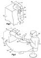
- FIG. 2is a schematic illustration depicting the manner in which a leg support is used to support an upper portion of a leg of a patient above a support surface on which the patient is disposed in a supine orientation during performance of knee surgery;
- FIG. 3is a schematic illustration depicting the patient's leg after a portion of a drape system has been positioned over the patient, the leg being shown in a flexed condition with the foot below the patient support surface and with an upper portion of the leg supported by the leg support of FIG. 2 ;
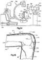
- FIG. 4is a schematic illustration of the patient's leg of FIGS. 2 and 3 in an extended condition and of the drape system which extends between a surgeon and the patient;
- FIG. 5is a schematic illustration depicting the manner in which the drape system of FIG. 4 maintains a sterile field during movement of the surgeon relative to the patient;
- FIG. 6is a schematic illustration depicting the manner in which an incision is made in the knee portion of the leg of the patient when the leg is in the position illustrated in FIGS. 2 and 3 ;
- FIG. 7is a schematic illustration depicting the manner in which the incision is expanded and a patella is everted with the leg of the patient extended;
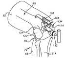
- FIG. 8is a schematic illustration depicting the manner in which a drill is utilized to form a passage in a femur in the upper portion of the leg of the patient with the leg in the position illustrated in FIGS. 2 and 3 and the patella offset from its normal position;
- FIG. 9is a schematic illustration of the positioning of a femoral alignment guide in the hole formed by the drill of FIG. 8 with the leg of the patient in the position illustrated in FIGS. 2 and 3 ;
- FIG. 10is a schematic illustration depicting the position of an anterior resection guide and a stylus relative to the femoral alignment guide of FIG. 9 before an anterior femur cut has been made with the leg of the patient in the position illustrated in FIGS. 2 and 3 ;
- FIG. 11is a schematic illustration, taken generally along the line 11 - 11 of FIG. 10 , further illustrating the relationship of the anterior resection guide and stylus to the distal end portion of the femur;
- FIG. 12is a schematic illustration further illustrating the relationship of the anterior resection guide and stylus to the distal end portion of the femur;
- FIG. 13is a schematic illustration depicting the manner in which a cutting tool is moved along a guide surface on the anterior resection guide during making of an anterior femur cut with the leg of the patient in the position illustrated in FIGS. 2 and 3 ;
- FIG. 14is a schematic illustration depicting the relationship of the femoral alignment guide to the femur after making of the anterior femur cut of FIG. 13 , the anterior resection guide and stylus being removed from the femoral alignment guide, and the leg of the patient being in the position illustrated in FIGS. 2 and 3 ;
- FIG. 15is a schematic illustration of the anterior femur cut and femoral alignment guide of FIG. 14 ;
- FIG. 16is a schematic illustration depicting the manner in which the femoral alignment guide is utilized to position a distal resection guide relative to the distal end portion of the femur after making of the anterior femur cut and with the leg of the patient in the position illustrated in FIGS. 2 and 3 ;
- FIG. 17is a schematic illustration depicting the manner in which a distal femur cut is made with a cutting tool after the femoral alignment guide has been removed, the leg of the patient being in the position illustrated in FIGS. 2 and 3 ;
- FIG. 18is a schematic illustration depicting the relationship of the cutting tool and distal resection guide of FIG. 17 to the femur;
- FIG. 19is a schematic illustration depicting the manner in which a femoral cutting guide is positioned on the distal end portion of the femur with the leg of the patient in the position illustrated in FIGS. 2 and 3 ;
- FIG. 20is a schematic illustration further depicting the relationship of the femoral cutting guide to the distal end portion of the femur;
- FIG. 21is a schematic illustration depicting the relationship of a tibial resection guide to the proximal end portion of a tibia in the lower portion of the patient's leg after making the femoral cuts and with the leg of the patient in the position illustrated in FIGS. 2 and 3 ;
- FIG. 22is a schematic illustration of the distal end portion of the femur and the proximal end portion of the tibia after making the femoral and tibial cuts with the leg of the patient in the position illustrated in FIGS. 2 and 3 and the patella offset to one side of the incision;
- FIG. 23is a schematic illustration further depicting the femoral and tibial cuts of FIG. 22 ;
- FIG. 24is a schematic illustration depicting the manner in which force is applied against the bottom of the patient's foot by a surgeon's knee with the leg of the patient in the position illustrated in FIGS. 2 and 3 ;
- FIG. 25is a schematic illustration depicting the various directions in which the lower portion of the patient's leg can be moved relative to the upper portion of the patient's leg to expose portions of the bone at the incision in the knee portion of the patient's leg and to check ligament balancing;
- FIG. 26is a schematic illustration depicting the manner in which a tibial punch is positioned relative to a tibial base plate with the leg of the patient in the position illustrated in FIGS. 2 and 3 ;
- FIG. 27is a schematic illustration depicting completed preparation of the tibia for a tibial tray implant with the leg of the patient in the position illustrated in FIGS. 2 and 3 ;
- FIG. 28is a schematic illustration depicting positioning of a tibial bearing insert in the tibial tray of FIG. 27 with the leg of the patient in the position illustrated in FIGS. 2 and 3 ;
- FIG. 29is a schematic illustration depicting femoral and tibial implants with the leg of the patient in the position illustrated in FIGS. 2 and 3 ;
- FIG. 30is a schematic illustration of an apparatus which may be utilized to move the lower portion of a patient's leg relative to the upper portion of a patient's leg when the patient's leg is in the position illustrated in FIGS. 2 and 3 ;
- FIG. 31is a schematic illustration depicting the manner in which a distal resection guide is connected with a patient's femur by pins which extend through the guide and through skin in the upper portion of the patient's leg into the femur with the leg of the patient in the position illustrated in FIGS. 2 and 3 ;
- FIG. 32is a schematic illustration depicting the manner in which an endoscope may be inserted through an incision in a patient's knee to inspect portions of the patient's knee which are remote from the incision with the leg of the patient in the position illustrated in FIGS. 2 and 3 ;
- FIG. 33is a schematic illustration similar to FIG. 32 , depicting the manner in which the endoscope may be inserted through the incision in the patient's knee with the leg of the patient extended;
- FIG. 34is a schematic illustration depicting the manner in which an imaging apparatus may be utilized to generate images of a portion of the patient's leg and the manner in which a robot may be utilized to position cutting tools or other devices relative to the patient's leg with the patient's leg in the position illustrated in FIGS. 2 and 3 ;
- FIG. 35is a schematic illustration depicting the relationship of a cut line to a patella in a knee of the leg of the patient with the leg in the position illustrated in FIGS. 2 and 3 and with the patella in the normal position;
- FIG. 36is a schematic illustration depicting the manner in which a cutting tool is moved relative to a guide member to cut the patella of FIG. 35 while the patella is disposed in situ;
- FIG. 37is a schematic illustration depicting the manner in which a tibial alignment shaft and a tibial resection guide are positioned relative to a tibia in a lower portion of a leg of the patient with the leg of the patient in the position illustrated in FIGS. 2 and 3 ;
- FIG. 38is an enlarged fragmentary view of a portion of FIG. 37 and illustrating the construction of the tibial resection guide
- FIG. 39is a schematic illustration depicting the relationship between an expandable cannula and an incision in the knee portion of one leg of the patient with the leg of the patient in the position illustrated in FIGS. 2 and 3 ;
- FIG. 40is a schematic illustration depicting the relationship between two separate portions of an implant which are interconnected within the patient's body;
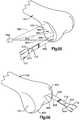
- FIG. 41is a schematic illustration depicting the relationship of transducers to a flexed knee joint of a patient when the leg of the patient is in the position illustrated in FIGS. 2 and 3 ;
- FIG. 42is a schematic illustration, generally similar to FIG. 41 , illustrating the relationship of the transducers to the knee joint when the leg of the patient is extended;
- FIG. 43is a schematic illustration of a distal end portion of a femur in a leg of a patient with the leg in the position illustrated in FIGS. 2 and 3 and illustrating the relationship of an implant to a recess in the end portion of the femur;
- FIG. 44is a schematic sectional view depicting the manner in which a cutting tool is used to form a recess in the end portion of the femur of FIG. 43 with the leg of the patient in the position illustrated in FIGS. 2 and 3 ;
- FIG. 45is a schematic sectional view, taken generally along the line 45 - 45 of FIG. 43 further illustrating the relationship of the implant to the recess;
- FIG. 46is a schematic end view of a proximal end portion of a tibia in a leg of a patient, with the leg in the position illustrated in FIGS. 2 and 3 , illustrating the relationship of an implant to a recess in the end portion of the tibia;
- FIG. 47is a schematic sectional view depicting the manner in which a cutting tool is used to form the recess in the end portion of the tibia of FIG. 46 ;
- FIG. 48is a schematic sectional view, taken generally along the line 48 - 48 of FIG. 46 , further illustrating the relationship of the implant to the recess;
- FIG. 49is a schematic sectional view illustrating the relationship of another implant to a recess in a bone in a patient's body
- FIG. 50is a schematic illustration depicting the relationship between a tibial implant and a tibia in the leg of the patient;
- FIG. 51is a schematic illustration depicting the relationship of expandable devices to the knee portion of a patient's leg
- FIG. 52is a schematic illustration depicting the manner in which an expandable device may be positioned relative to a knee portion of a patient's leg with the patient's leg in the position illustrated in FIGS. 2 and 3 ;
- FIG. 53is a schematic illustration depicting the manner in which a femoral cutting guide may be mounted on a distal end of a femur in a patient's leg with the patient's leg in the position illustrated in FIGS. 2 and 3 ;
- FIG. 54is a schematic illustration of the manner in which a femoral cutting guide may be mounted on a side surface of a femur in a patient's leg with the patient's leg in the position illustrated in FIGS. 2 and 3 ;
- FIG. 55is a schematic illustration depicting the manner in which light is directed onto a distal end portion of a femur with the patient's leg in the position illustrated in FIGS. 2 and 3 ;
- FIG. 56is a schematic illustration depicting the manner in which light is used to guide movement of a cutting tool relative to a distal end portion of a femur with the patient's leg in the position illustrated in FIGS. 2 and 3 ;
- FIG. 57is a schematic illustration depicting the manner in which a cutting tool is moved relative to a secondary incision with a knee portion of a patient's leg in the position illustrated in FIGS. 2 and 3 ;
- FIG. 58is schematic illustration depicting the relationship of transducers to a patella and distal end portion of a femur with the patient's leg in the position illustrated in FIGS. 2 and 3 .
- a patientis supported on an operating table or other support surface 52 ( FIG. 1 ).
- a leg 50 of the patientis in the extended position illustrated in dashed lines in FIG. 1
- a foot 54 connected with a lower portion 56 of the leg 50is disposed above the support surface 52 .
- the knee portionis raised and lowered relative to the support surface as the leg 50 is flexed and extended.
- the foot 54is always disposed above the support surface 54 and may be supported by the support surface throughout the operation.
- an incisionis made in the knee portion 58 of the leg 50 when the leg is in the extended position illustrated in dashed lines in FIG. 1 .
- the foot 54 of the patientmay rest on the support surface 52 or be disposed in a foot support located above the support surface.
- the leg 50may be flexed or bent to the position illustrated in solid lines in FIG. 1 .
- the leg 50As the knee portion 58 is bent, the leg 50 is flexed and compresses the soft tissue of the knee portion 58 against the back of the knee joint. This makes it very difficult to access the posterior of the knee portion 58 to remove bone spurs (ostified), the meniscus, the posterior capsule, and/or any residual soft tissue or bone that is blocking further flexion. The catching or pinching of soft tissue in the posterior aspect of the knee portion 58 may prevent further flexion and limits the range of motion. In addition, arteries, nerves and veins are sitting just posterior of the knee joint.
- Cutsare made on a femur and tibia with the leg 50 in the bent or flexed condition, illustrated in FIG. 1 . This results in the distal end portion of the femur and the proximal end portion of the tibia in the leg 50 being pressed together adjacent to the cuts. This interferes with ligament balancing.
- the relatively large incisionwhich is necessary to accommodate known instrumentation systems increases time required for the patient to recover from the operation.
- various features and/or combinations of features of the present inventionwill be utilized during surgery on different portions of a patient's body, such as a head, trunk or limbs of a patient. Although at least some of the features of the present invention are believed particularly advantageous when utilized in association with surgery on any one of the many joints in a patient's body, it is believed that the various features and/or combination of the features of the present invention are particularly advantageous when utilized in conjunction with surgery on a knee portion of a leg of a patient. It should be understood that the various features of the present invention may be use separately or in any desired combination of features.
- Surgery on the knee portion of the patientmay relate to any one of many different aspects of the knee portion, such as ligaments, tendons, articular surfaces, and/or total or partial knee replacements or revisions.
- the disclosure hereinfrequently refers to one particular type of knee operation, that is, a total knee replacement, features of the invention may be utilized with any desired type of surgery. It is believed that it will be apparent to a person having a knowledge of knee surgery how various features of the invention may be utilized with either a full or partial knee replacement. Therefore, there has been only minimal mention herein of how the features of the invention are applicable to partial knee replacements.
- the patient 62( FIG. 2 ) is disposed on a support surface 64 of an operating table 66 .
- a patient support surface 64other than an operating table could be used to support the patient.
- a lower portion 68 of a leg 70extends downward from an upper portion 72 of the leg 70 .
- a foot 74 connected with the lower portion 68 of the leg 70is disposed below the support surface 64 .
- the leg 70is flexed so that a knee portion 76 of the leg is bent.
- the upper portion 72 of the leg 70is supported above the support surface 64 by a leg support 80 ( FIG. 2 ).
- the leg support 80includes a stand or base section 82 which is connected with the operating table 66 .
- the leg support 80includes a base 84 which is connected with an upper end portion of the stand 82 .
- the base 84is engaged by and supports the upper portion 72 of the leg 70 .
- a generally annular thigh holder 86extends around the upper portion 72 of the leg 70 of the patient and is connected with the base 84 and stand 82 .
- the base 84has a portion which extends along the posterior side of the upper portion 72 of the leg 70 of the patient.
- the base 84supports the upper portion 72 of the leg 70 above and spaced from the support surface 64 .
- the upper portion 72 of the leg 70could be disposed in engagement with the support surface 64 if desired.
- the leg support 80supports the leg 70 of the patient with a hip 88 of the patient hyperflexed at an angle of twenty to thirty degrees throughout the operation on the knee portion 76 .
- the leg support 80may have a known commercial construction or may have a construction similar to that disclosed in U.S. Pat. No. 4,373,709 or U.S. Pat. No. 6,012,456. If desired, a tourniquet may be combined with the leg support 80 in a manner similar to that provided in known leg supports or in a manner similar to that disclosed in U.S. Pat. No. 4,457,302.
- the lower portion 68 ( FIG. 3 ) of the leg 70is suspended from the upper portion 72 of the leg.
- the foot 74 and ankle portion 86 of the leg 70 of the patientcan be moved anteriorly or upward (as viewed in FIG. 3 ) to decrease the extent of flexion of the knee portion 72 or even to extend or straighten the leg 70 .
- the foot 74 and ankle portion 86may be moved posteriorly toward the operating table 66 , from the position illustrated in FIG. 3 , to hyperflex the knee portion 72 of the leg of a patient.
- the foot 74may be moved sidewardly, that is in either a lateral or medial direction.
- the foot 74may be rotated about the longitudinal central axis of the lower portion 68 of the leg 70 .
- foot 74 and ankle portion 86may be simultaneously moved in a plurality of the directions previously mentioned. If desired, the upper portion 72 of the leg 70 of the patient may be supported on a separate section of the operating table 66 , in a manner similar to the disclosure in U.S. Pat. No. 5,007,912.
- the leg 70extends out of the drape.
- the drape 90may be connected with the leg support 80 and have an opening 92 ( FIGS. 3 and 4 ) through which the leg of the patient extends. This enables the leg 70 of a patient to be moved between the extended position illustrated in FIG. 4 and a hyperflexed position in which the foot 74 is disposed posteriorly from the position illustrated in FIG. 3 .
- the included angle between the upper and lower portions 72 and 68 of the leg 70is less than ninety degrees.
- the leg 70may be flexed from the extended position of FIG. 4 to a hyperflexed position by manually moving the foot 74 and an ankle portion 96 of the leg 70 relative to the operating table 66 ( FIG. 2 ) while the upper portion 72 of the leg is held by the leg support 80 .
- a portion of the foot 74may be disposed beneath the operating table 66 ( FIG. 2 ).
- An improved drapery system 100( FIG. 4 ) includes the drape 90 and a drape 102 connected with a gown 104 on a surgeon 106 .
- the illustrated drape 102is formed separately from the drape 90 and gown 104 .
- the drape 102may be integrally formed as one piece with the drape 90 .
- the drape 102may be integrally formed as one piece with the gown 104 .
- the drape 102is formed separately from the gown 104 and the drape 90 .
- the drape 102is connected to the drape 90 by suitable clamps 108 .
- the drape 102is connected with the waist of the surgeon 106 by clamps 110 to the gown 104 .
- the drapescould be interconnected by Velcro, ties, or other known devices. Of course, similar devices could be utilized to connect the drape 102 with the gown 104 of the surgeon 106 .
- the improved drapery system 100maintains a sterile field between the leg 70 and the surgeon 106 during movement of the surgeon relative to the patient 62 .
- the drapery system 100provides a sterile field which extends from the surgeon to the space beneath and adjacent to the leg 70 .
- the drapery system 100continues to maintain a sterile field between the surgeon and the patient. This enables the surgeon 106 to move the leg 70 of a patient during an operation without contaminating the sterile field.
- the draping system 100enables the sterile field to be maintained when the patient's leg is moved between the extended position of FIGS. 4 and 5 and a hyperflexed position in which the foot 74 of the patient is disposed beneath the operating table 66 .
- the drape 102moves with the surgeon and maintains a sterile field.
- the end portion of the drape 102 connected with the surgeonalso moves toward and away from the patient.
- a portion of the drape 102 between the surgeon 106 and patientis lowered.
- the portion of the drape 102 between the surgeon and patientis raised.
- the foot 74 connected with the leg 70 of the patientis always above the drape 102 during movement of the surgeon 106 .
- the drapery system 100may be used in association with surgery on any desired portion of a patient's body.
- the drapery system 100could be used to maintain a sterile field between a surgeon and patient during surgery on a trunk portion of a patient's body.
- the drapery system 100could be used to maintain a sterile field during surgery on a head or arm portion of a patient's body.
- a limited incision 114( FIG. 6 ) is formed in the knee portion 76 of the leg 70 .
- the incision 114is made just medial to the patella 120 .
- the incision 114could be disposed laterally of the patella 120 .
- the length of the incision 114may vary depending upon the circumstances, the incision 114 will usually have a length of between about seven (7) and about thirteen (13) centimeters. However, even smaller incisions may be made when circumstances permit.
- the incisionis made when the knee portion 76 of the leg is flexed and the lower portion 68 of the leg extends downward from the upper portion 72 of the leg in the manner illustrated in FIGS. 2 and 3 .
- the upper portion 72 of the leg 70is supported above the support surface 64 by the leg support 80 ( FIG. 2 ).
- the lower portion 68 of the leg 70is suspended from the upper portion 72 of the leg ( FIGS. 2 and 3 ).
- the incision 114may have a length of approximately ten (10) centimeters.
- the leg 70is straightened from the flexed condition of FIGS. 2 and 3 to the extended condition of FIGS. 4 and 5 , the length of the incision 114 may decrease by between ten and thirty percent.
- an incision 114had a length of approximately eleven (11) centimeters when the leg 70 was in the flexed condition of FIGS.
- the incision 114By making the incision 114 with the leg in a flexed condition ( FIGS. 2 , 3 , and 6 ) and operating on the leg 70 with the leg in a flexed condition, the overall length of the incision can be reduced from the length of incisions which have previously been made in the leg when it is in the extended condition.
- the incision 114located adjacent to the medial edge of the patella 120 , in the manner illustrated schematically in FIG. 6 .
- the incision 114could be located adjacent to the lateral edge of the patella 120 if desired.
- the incision 114could be disposed midway between lateral and medial edges of the patella 120 .
- the incisionmay have a length of approximately twice the length of the patella. It may be desired to have the incision 114 extend from a proximal end of the tibia in the leg 70 to the epicondylar notch on the distal end portion of the femur in the leg 70 .
- the length and location of the incision 114may vary depending on the size of the implants to be positioned in the knee portion 76 and the location at which the implants are to be positioned. It is believed that it may be desired to have the incision 114 be smaller than the implants even though the implants must move through the incision.
- the visoelastic nature of the body tissue and mobility of the incision 114enables the implants to be larger than the incision and still move through the incision.
- a straight incision 114has been illustrated in FIG. 6 .
- the incision 114could have a different configuration if desired.
- the incision 114could have an L-shaped configuration.
- the incision 114could be skewed at an acute angle to a longitudinal central axis of the patella 120 .
- the incision 114could have a configuration matching the configuration of either the lateral or medial edge of the patella 120 .
- the leg 70may be moved from the flexed condition of FIGS. 2 and 3 to the extended condition of FIG. 5 . While the leg 70 is in the extended condition, the incision 114 ( FIG. 7 ) is elastically expanded using suitable retractors.
- the retractorsapply force against the visoelastic body tissue of the knee portion 76 .
- the retractorshave a construction similar to that disclosed in U.S. Pat. No. 5,308,349.
- a pneumatic retractorsuch as is disclosed in U.S. patent application Ser. No. 09/526,949 filed on Mar. 16, 2000 by Peter M. Bonutti may be utilized to expand the incision.
- a patella 120 and tissue on the lateral side of the incisionmay be everted in a manner illustrated in FIG. 7 .
- the patella 120is moved from the normal orientation of FIG. 6 to the everted or flipped orientation of FIG. 7 while the leg 70 of the patient is in the extended orientation of FIG. 7 .
- the inner side 122 of the patella 120is facing outward away from other bones in the knee portion 76 .
- the outer side of the everted patella 120is facing inward toward other bones in the knee portion 76 . This enables the inner side 122 of the patella 120 to be examined.
- the patella 120is returned back to its normal position with the inner side 122 of the patella facing inward and the outer side of the patella facing outward. As this occurs, the opening at the incision 114 contracts.
- the retractorsare then utilized to apply force against opposite sides of the incision 114 . As this occurs, the visoelastic body tissue is extended, the opening at the incision 114 is again expanded, and the patella 120 is pushed to the lateral side of the knee portion 76 . This moves the patella 120 to a location offset to one side of the incision 114 in a manner illustrated in FIG. 8 .
- the leg 70is then flexed to the orientation shown in FIGS. 2 and 3 .
- the foregoing step of inverting the patella 120may be omitted.
- the patella 120may be left in orientations in which the inner side 122 of the patella faces inward throughout the operation. If this is done, the inner side 122 of the patella 120 may be inspected by tilting the patella from its normal orientation and/or using viewing devices, such as an endoscope. Regardless of how the inner side 122 of the patella 120 is inspected, moving the patella to the offset position of FIG. 8 , with the inner side 122 facing inward, facilitates utilization of an incision 114 having a limited length. It is contemplated that many different surgical procedures could be conducted on the knee portion 76 with the patella 120 in the offset position of FIG. 8 .
- Expansion of the incision 114 with the known retractorsexposes a distal end portion 124 ( FIG. 8 ) of a femur 126 in the upper portion 72 of the leg 70 .
- the incision 114is movable relative to the distal end portion 124 of the femur 126 to maximize exposure of the femur through the limited length of the incision.
- the femur 126is then cut to receive an implant.
- intramedullary or extramedullary instrumentationcan be utilized, intramedullary instrumentation is used during cutting of the femur 126 . Therefore, a drill 128 is utilized to access the intramedullary canal or marrow cavity in the femur 126 .
- the drill 128is utilized to form a hole 130 in the center of the intercondylar notch in the distal end portion 124 of the femur 126 in a known manner.
- the drill 128is used to form the hole 130 while the leg 70 is in the orientation illustrated in FIGS. 2 and 3 .
- the patella 120is in the offset position illustrated in FIG. 8 . At this time, the inner side 122 ( FIG. 7 ) of the patella faces toward the femur 126 .
- An epicondylar reference guide(not shown) engages the hole in the distal end portion 124 of the femur 126 to enable a line parallel to an epicondylar axis peaks of the medial and lateral condyles to be inscribed on the distal end portion 124 of the femur 126 .
- the leg 70is in the orientation illustrated in FIGS. 2 , 3 , 8 and 9 .
- a shaft 132 ( FIGS. 9 , 10 , 11 and 12 ) of a femoral alignment guide 134is then inserted into the intermedullary opening 130 .
- the femoral alignment guide 134is then aligned with the epicondylar line which extends parallel to the epicondylar axis through the peaks of the lateral and medial condyles on the distal end portion 124 of the femur 126 .
- the femoral alignment guide 134is utilized to support an anterior resection guide 138 and stylus 140 ( FIGS. 10 , 11 and 12 ) on the distal end portion 124 of the femur 126 in the upper portion 72 of the leg 70 of the patient.
- FIGS. 10 , 11 and 12it should be understood that the leg 70 is in the orientation illustrated in FIGS. 2 and 3 .
- the upper portion 72 of the leg 70us supported by the leg support 80 .
- the instrumentationis down sized to enable the size of the incision 114 ( FIG. 9 ) to be minimized.
- the downsized instrumentationhas a transverse dimension which is smaller than a transverse dimension of an implant to be placed in the knee portion 76 ( FIG. 9 ).
- the femoral alignment guide 134 and anterior resection guide 138have transverse dimensions, perpendicular to a longitudinal central axis of the femur 126 , which are smaller than transverse dimensions of a femoral implant 290 , tibial bearing insert 294 , and a tibial tray 286 ( FIG. 29 ) in a direction perpendicular to the longitudinal central axis of the femur 126 ( FIG. 9 ).
- the instrumentationextends from a center portion of the femur 126 toward one side of the femur ( FIG. 11 ).
- the incision 114is offset to the medial side of the patella 120 . Therefore, the instrumentation is offset to the medial side of the femur 126 . However, if the incision 114 is offset to the lateral side of the patella 120 , the instrumentation would be offset to the lateral side of the femur 126 . If the incision 114 was centrally disposed relative to the femur 126 , the instrumentation would be centrally disposed relative to the femur. Thus, the instrumentation is in general alignment with the incision 114 and extends only part way across the distal end portion 124 of the femur 126 .
- the femoral alignment guide 134( FIGS. 10 , 11 and 12 ) and anterior resection guide 138 have opposite ends which are spaced apart by distance which is less than a distance between epicondyles 148 and 150 on the distal end portion 124 of the femur 126 .
- the distance between opposite ends 154 and 156 of the femoral alignment guide 134is less than two thirds (2 ⁇ 3) of the distance between tips 144 and 146 of the lateral and medial epicondyles 148 and 150 .
- a distance between an end 160 and an opposite end 162 of the anterior resection guide 138is less than two thirds (2 ⁇ 3) of the distance between the tips 144 and 146 of the lateral and medial epicondyles 148 and 150 .
- the distance between opposite ends of a known femoral alignment guide and the distance between opposite ends of a known anterior resection guideare approximately the same as or greater than the distance between the tips 144 and 146 of the lateral and medial condyles 148 and 150 .
- the distance between opposite ends of the known femoral alignment guide and the distance between opposite ends of the known anterior resection guideare greater than the transverse dimensions of the femoral and tibial implants 286 , 290 and 294 ( FIG. 29 ).
- This known anterior resection guide and femoral alignment guideare commercially available from Howmedica Osteonics of 359 Veterans Boulevard, Rutherford, N.J. under the designation “Scorpio” (trademark) Single Axis Total Knee System.
- the incision 114must be large enough to enable the femoral alignment guide 134 and the anterior resection guide 138 to pass through the incision.
- the size of the incision 114can be reduced.
- reducing the size of the incision 118reduces damage to body tissue of the patient 62 .
- the femoral alignment guide 134 and the anterior resection guide 138may be larger than the incision 114 . This is because the incision 114 can be resiliently stretched and/or moved relative to the femur 126 to enable the femoral alignment guide 134 and anterior resection guide 138 to move through the incision.
- the distance between opposite ends 154 and 156 of the femoral alignment guide 134is less than the distance which a femoral implant extends across the distal end portion 124 of the femur 126 .
- the distance between opposite ends 160 and 162 of the anterior resection guide 138is less than the distance which the femoral implant extends across the distal end portion 124 of the femur 126 .
- the femoral alignment guide 134 and the anterior resection guide 138both extend medially from a center portion of the femur 126 .
- the femoral alignment guide 134 and the anterior resection guide 138would extend laterally from the center portion of the femur 126 .
- the femoral alignment guide 134 and anterior resection guide 138would be centered relative to the femur 126 .
- Positioning of the femoral alignment guide 134 and anterior resection guide 138 on the distal end portion 124 of the femur 126is facilitated by distracting the knee joint under the influence of the weight of the lower portion 68 of the patient's leg and the foot 74 .
- the femoral alignment guide 134 and anterior resection guide 138are positioned on the distal end portion 124 of the femur 126 , the lower portion 68 of the leg 70 is suspended from the upper portion 72 of the leg.
- the foot 74is below the level of the support surface 64 ( FIG. 2 ) on which the patient is disposed in a supine orientation.
- the upper portion 72 of the patient's leg 70is supported above the support surface 64 by the leg support 80 ( FIG. 2 ).
- the distal end portion 124 of the femur 126is exposed through the relatively small incision 114 ( FIG. 9 ). Exposure of the distal end portion 124 of the femur 126 at the limited incision 114 is promoted by moving the lower portion 68 of the leg 70 and the incision relative to the femur. In addition, exposure of the distal end portion 124 of the femur 126 is promoted by having the patella 120 offset to the lateral side of its normal position. The inner side 122 of the patella 120 faces inward toward the distal end portion 124 of the femur 126 so that the skin on the knee portion 76 is not excessively stretched by everting the patella.
- the instrumentationis at least partially positioned between the distal end portion 124 of the femur 126 and body tissue of the knee portion 76 ( FIG. 9 ).
- the instrumentationis moved laterally of the incision so that a portion of the instrumentation moves between the knee capsule and the end portion 124 of the femur 126 . This results in a portion of the instrumentation being exposed at the incision 114 and a laterally extending portion of the instrumentation being concealed by body tissue.
- the end 154FIG.
- the femoral alignment guide 134 and/or the end 160 of the anterior resection guide 138are overlaid by body tissue adjacent to the lateral edge portion of the incision 114 .
- the body tissue which overlies portions of the instrumentationmay include skin, the knee capsule, and connective and soft tissues.
- central axis of the femoral alignment guide and anterior resection guideare medially offset from the central axis of the femur.
- the central axis of the femur 216extends through a lateral portion, that is, left portion as viewed in FIG. 11 , of the femoral alignment guide 134 .
- the anterior resection guide 138is almost entirely offset to the right (as viewed in FIG. 11 ) of the central axis of the femur 126 .
- the incision 114is disposed along a medial edge, that is, a right edge as viewed in FIG. 6 , of the patella 120 when the patella is in its normal or initial position.
- the central portion of the instrumentationis exposed at the incision.
- the medial edge of the incisionoverlaps the medial end 156 of the femoral alignment guide 134 and the medial end 162 of the anterior resection guide 138 .
- the lateral edge of the incision 114overlaps the lateral end 154 of the femoral alignment guide 134 and the lateral end 160 of the anterior resection guide 138 .
- the leg 70 ( FIG. 3 ) of the patient 62 ( FIG. 2 )is maintained in the position illustrated in FIGS. 2 and 3 with the foot 74 of the patient below the support surface 64 upon which the patient is supported in a supine position during forming of the incision 114 in the knee portion 76 of the leg 70 .
- the upper portion 72 of the patient's leg 70is supported above the support surface 64 by the leg support 80 ( FIG. 2 ).
- the leg of the patientis maintained in the position illustrated in FIGS. 2 and 3 during connection of the femoral alignment guide 134 and anterior resection guide 138 with the distal end portion 124 of the femur 126 .
- an anterior cutis made in the manner illustrated in FIG. 13 .
- a blade 170 of a saw 172is utilized to make a cut across anterior portions of the lateral and medial condyles.
- the saw blade 170is moved along guide surface 178 ( FIGS. 11 and 12 ) on the anterior resection guide 138 .
- the guide surface 178extends only part way across of the end portion 124 of the femur 126 ( FIGS. 11 and 13 ).
- the guide surface 178does not extend across the lateral portion of the end portion 124 of the femur 126 .
- the incision 114extends along the medial edge portion of the patella 120 when the patella is in its normal, that is, initial, position.
- the large majority of the anterior resection guide 138extends medially from the central axis of the shaft 132 of the femoral alignment guide 134 ( FIG. 11 ).
- the blade 170When anterior portions of the lateral and medial condyles 148 and 150 ( FIGS. 10 , 11 and 12 ) on the distal end portion 124 of the femur 126 are to be cut with the saw 172 , the blade 170 is pivoted sideways ( FIG. 13 ) so that the cutting end of the blade has an arcuate component of movement. The cutting end of the blade 170 will move along a straight path during part of the movement of the blade along the guide surface 178 . However, when the blade 170 reaches the ends of the guide surface 178 , the saw 172 is pivoted to pivot the blade and move the cutting end of the blade along a path having an arcuate configuration. This results in a generally fan shaped cut which extends only part way across the anterior side of the lateral and medial condyles on the end portion 124 of the femur.
- the saw blademay have teeth along opposite longitudinally extending edges.
- the saw blade 170 and saw 172are of the oscillating type. However, a reciprocating type saw and blade may be utilized if desired.
- the saw blade 170is moved along the guide surface 178 to only partially complete the anterior skim cut on the end portion 124 of the femur 126 .
- the guide surface 178is offset to the medial side of the central axis of femur 126 ( FIG. 11 ). Therefore, the saw blade can only partially form the lateral portion of the anterior skim cut while the saw blade engages the guide surface 178 .
- the anterior resection guide 138is then disconnected from the femoral alignment guide 134 ( FIGS. 14 and 15 ) and the anterior femur cut is completed.
- the saw blade 170is then moved along the previously cut surfaces on the distal end portion of the femur 126 to guide the saw blade during completion of the anterior skim cut. Utilizing cut surfaces formed during an initial portion of the anterior skim cut to guide the saw blade 170 enables the size of the anterior resection guide 138 to be minimized.
- the illustrated saw blade 170has teeth 180 at only one end, the saw blade could also have teeth along opposite longitudinally extending edges.
- the overall length of the anterior resection guidethat is, the distance between the ends 160 and 162 ( FIG. 11 ) of the anterior resection guide can be limited to a distance which is less than the distance between the epicondyles 148 and 150 .
- the distance between the ends 160 and 162 of the anterior resection guide 138is less than two thirds (2 ⁇ 3) of the distance between the tips 144 and 146 of lateral and medial epicondyles 148 and 150 on the distal end portion 124 of the femur 126 .
- the initial portion of the anterior skim cutcould be made with a first cutting tool and the anterior skim cut completed with a second cutting tool.
- the initial portion of the anterior skim cutmay be made with relatively small oscillating saw blade.
- the final portion of the anterior skim cutmay be made with a larger reciprocating saw blade.
- a small milling cuttercould be used to make the initial portion of the anterior skim cut.
- the final portion of the skim cutcould be made with a relatively long milling cutter or saw blade. It may be desired to make the initial portion of the anterior skim cut with a chisel and to complete the anterior skim cut with either a saw blade or a milling cutter.
- the illustrated anterior resection guide 138has a slot which forms the guide surface 178 . This results in the saw blade 170 being captured so that the saw blade is restrained against both up and down movement (as viewed in FIG. 11 ) relative to the anterior resection guide 138 . However, in order to reduce the size of the anterior resection guide 138 , the slot could be eliminated and the saw blade 170 moved along a flat outer side of the anterior resection guide.
- body tissue( FIG. 9 ) overlies at least portions of the lateral and medial condyles being cut. This is due to the relatively short extent of the incision 114 .
- the saw blade 170 and the portion of the femur 126 being cut by the saw bladeare both at least partially enclosed by body tissue overlying the femur during making of the anterior skim cut.
- the incision 114is moved relative to the femur 126 to provide clearance for the saw blade.
- a flat anterior cut surface 182( FIGS. 14 and 15 ) is disposed on the distal end portion 124 of the femur 126 .
- the anterior skim cutis made on the distal end portion 124 of the femur 126 with the patella 120 offset to one side of the incision 118 ( FIG. 14 ).
- the inner side of the patella 120faces toward the distal end portion 124 of the femur 126 when the patella is in the offset position of FIGS. 9 and 14 .
- the flat anterior cut surface 182( FIG. 15 ) extends parallel to the epicondylar axis.
- the maximum width of the anterior cut surface 182is greater than the distance between opposite ends 154 and 156 ( FIG. 11 ) of the femoral alignment guide 134 .
- the maximum width of the anterior cut surface 182 ( FIG. 15 )is greater than the distance between opposite ends 160 and 162 ( FIG. 11 ) of the anterior resection guide 138 .
- the anterior cut surface 182is at least partially covered by body tissue which encloses the distal end portion of the femur 126 ( FIG. 14 ).
- the patient 62( FIG. 2 ) is supported in a supine position on the support surface 64 .
- the upper portion 72 of the leg 70is disposed above the support surface on the leg support 80 .
- the lower portion 68 of the leg 70extends downward from the support surface 64 .
- the foot 74 ( FIG. 3 ) of the patientis disposed below the support surface.
- the lower portion 68 of the leg 70is suspended from the upper portion 72 of the leg in the manner illustrated in FIG. 3 .
- the lower portion 68 of the leg 70dangles from the upper portion 72 of the leg.
- a holdercould be provided to engage either the foot 74 and/or the lower portion 68 of the leg 70 to maintain the foot 74 and lower portion 68 of the leg in a desired position relative to the support surface 64 .
- a distal resection guide 186is positioned relative to the flat anterior skim cut surface 182 ( FIG. 16 ).
- a resection guide stand 190is mounted on the femoral alignment guide 134 in the manner illustrated in FIG. 16 .
- the distal resection guide 186is connected with the resection guide stand 190 by rotating a locking knob 192 .
- the distal resection guide 186 and resection guide stand 190may be magnetized to assure correct assembly. Since the femoral alignment guide 134 is medially offset relative to the distal end portion 124 of the femur 126 , the distal resection guide 186 is also medially offset relative to the distal end portion of the femur.
- the distal resection guide 186When the distal resection guide 186 is to be connected with the resection guide stand 190 , the distal resection guide is moved between the anterior skim cut surface 182 and body tissue overlying the anterior skim cut surface ( FIG. 14 ). Thus, due to the limited extent of the incision 114 , skin and other body tissues are disposed over the anterior skim cut surface 182 . The distal resection guide 186 slides between the anterior skim cut surface 182 and the body tissue overlying the anterior skim cut surface. A lower (as viewed in FIGS. 16 , 17 and 18 ) major side of the distal resection guide 186 engages the anterior skim cut surface 182 . The opposite or upper (as viewed in FIGS.
- the distal resection guide 186is engaged by the body tissue overlying the anterior skim cut surface 182 ( FIG. 14 ).
- the surgeonmoves the incision 114 and/or the lower portion 68 of the leg 70 relative to the distal end portion of the femur 126 to facilitate movement of the distal resection guide 186 onto the anterior skim cut surface 182 .
- the distal resection guide 186is secured in place with pins 196 and 198 ( FIG. 16 ).
- body tissueoverlies the portion of the distal resection guide 186 spaced from the distal end of the femur.
- the distal resection guide 186is medially offset from a central portion of the femur 126 and is aligned with the incision 114 .
- the incision 114( FIG. 14 ) is moved relative to the distal end portion 124 of the femur 216 to enable the pins 196 and 198 to be forced into the distal end portion of the femur.
- the femoral alignment guide 134 and resection guide stand 190are then separated from the distal end portion 124 of the femur 126 ( FIGS. 17 and 18 ). As this is done, the resection guide stand 190 ( FIG. 16 ) is separated from the distal resection guide 186 . Separation of the resection guide stand 190 from the distal resection guide 186 is accomplished by rotating the knob 192 and moving the resection guide stand 190 upward (as viewed in FIG. 16 ) to disconnect the guide stand 190 from the femoral alignment guide 134 . The intramedullary rod 132 and femoral alignment guide 134 are then removed from the femur 126 . The distance between opposite ends 206 and 208 of the distal resection guide 186 is less than two thirds (2 ⁇ 3) of the distance between tips 144 and 146 ( FIG. 11 ) of the lateral and medial epicondyles 148 and 150 .
- the distal resection guide 186is down sized to enable the distal resection guide to move into the knee portion 76 of the patient's leg 70 through a relatively small incision 114 .
- opposite ends 206 and 208 ( FIG. 16 ) of the distal resection guide 186are spaced apart by a distance which is less than the distance between the lateral and medial epicondyles 148 and 150 ( FIG. 11 ) on the distal end portion 124 of the femur 126 .
- the distance between opposite ends 206 and 208 of the distal resection guide 186is less than the distance which a femoral implant extends across the distal end portion 124 of the femur 126 .
- the distal resection guide 186is offset medially relative to the distal end portion 124 of the femur 126 .
- the incision 114is also medially offset relative to the distal end portion 124 of the femur 126 . This results in the central portion of the guide surface 202 being exposed through the incision 114 .
- the lateral and medial edges of the incision 114overlap opposite ends 206 and 208 of the distal resection guide 186 .
- the incision 114also overlaps the anterior side, that is, the upper side as viewed in FIG. 16 , of the distal resection guide.
- the incision 114is elastically expanded with suitable retractors.
- the saw blade 170moves along the guide surface 202 ( FIG. 17 ) on the distal resection guide 186 .
- the guide surface 202 on the down sized distal resection guide 186has a length which is less than a transverse dimension of a cut to be made in the distal end portion 124 of the femur 126 .
- the saw 172may be pivoted, in a manner illustrated schematically in FIG. 13 , adjacent to opposite ends of the guide surface 202 . This moves the cutting end of the saw blade 170 along an arcuate path to form a generally fan shaped distal femoral cut.
- the saw 172may be either a reciprocating or oscillating saw.
- the saw blade 170( FIGS. 17 and 18 ) is ineffective to complete the distal femoral cut while the saw blade is in engagement with the guide surface 202 ( FIGS. 16 and 17 ). Therefore, after an initial portion of the distal cut has been made by moving the saw blade 170 along the guide surface 202 , the distal resection guide 186 is disconnected from the distal end portion 124 of the femur 126 and the distal femoral cut is completed.
- surfaces formed during the initial portion of the distal femoral cutare effective to guide the saw blade 170 .
- the saw blade 170( FIGS. 17 and 18 ) is moved into the saw kerf or slot formed during the initial portion of the distal femoral cut. As the saw blade 170 extends the initial portion of the distal femoral cut, the saw blade slides along cut surfaces formed during the initial portion of the distal femoral cut. Thus, cut surfaces formed during movement of the saw blade 170 along the guide surface 202 are utilized to guide movement of the saw blade during completion of the distal femoral cut.
- the initial portion of the distal femoral cutmay be made with a first cutting tool and the final portion of the distal femoral cut may be made with a second cutting too.
- the initial portion of the distal femoral cutmay be made with a relatively small oscillating saw blade which can be readily inserted through the incision 114 into engagement with the distal resection guide 186 .
- the final portion of the distal femoral cutmay be made with a larger saw blade which may be of the reciprocating type. It is contemplated that the initial and/or final portion of the distal femoral cut may be made with a milling cutter. It is also contemplated that a chisel may be used to make the initial and/or final portion of the distal femoral cut.
- a flat distal end surface 209extends across the distal end of the femur 126 ( FIG. 17 ).
- the distal end surface 209extends perpendicular to the anterior cut surface 182 .
- the maximum width of the distal end surface 209is greater than the distance between opposite ends 206 and 208 of the distal resection guide 186 .
- the trochlear groove of the femurextends through the distal end surface 209 .
- the distal femoral cutis formed with the patella 120 ( FIG. 14 ) offset to one side of the incision 114 and with the inner side 122 of the patella facing toward the distal end portion 124 of the femur 126 .
- the leg 70 of the patientis in the orientation illustrated in FIGS. 2 and 3 with the foot 74 and lower portion 68 of the leg suspended from the upper portion 72 of the leg.
- the upper portion 72 of the legis supported above the support surface 64 by the leg support 80 .
- a femoral cutting guide 210( FIGS. 19 and 20 ) is then positioned on the distal end portion 124 of the femur 126 and utilized to make femoral anterior, posterior and chamfer cuts in a known manner.
- the femoral cutting guide 210is connected with the distal end portion 124 of the femur 126 by two pins (not shown) in a known manner.
- the femoral cutting guide 210is down sized so that it has opposite ends which are spaced apart by distance which is less than a distance between the lateral and medial epicondyles 148 and 150 ( FIG. 11 ) on the distal end portion 124 of the femur 126 .
- the femoral cutting guide 210is offset in a medial direction from the center of the femur 126 ( FIG. 20 ).
- the medially offset position of the femoral cutting guide 210is the result of the medially offset position of the incision 114 ( FIG. 6 ).
- the initial portion of the femoral anterior, posterior and chamfer cutsare made by moving the saw blade 170 or other cutting tool along guide surfaces on the femoral cutting guide. Due to the relatively small size of the femoral cutting guide, the cuts cannot be completed while moving the saw blade 170 or other cutting tool along guide surfaces on the femoral cutting guide. Therefore, the femoral cutting guide 210 is separated from the distal end portion 124 of the femur 126 and the cuts are completed while guiding movement of the saw blade 170 or other cutting tool with cut surfaces formed during the making of the initial portions of the femoral anterior, posterior and chamfer cuts. When the femoral anterior, posterior and chamfer cuts are completed, the distal end portion 124 of the femur 126 will have the known configuration illustrated in FIGS. 22 and 23 .
- the femoral cutting guide 210may have the same construction as a femoral cutting guide which is commercially available from Howmedica Osteonics of 359 Veterans Boulevard, Rutherford, N.J.
- the femoral cutting guidemay have the construction disclosed in U.S. Pat. No. 5,282,803 or 5,749,876.
- femoral cutting guide 210Since the femoral cutting guide 210 is down sized, initial portions of the femoral anterior, posterior and chamfer cuts are made while guiding a saw blade or other cutting tool with the femoral cutting guide. These cuts are subsequently completed utilizing previously cut surfaces to guide the saw blade 170 . To complete a cut in this manner, the saw blade 170 or other cutting tool is moved along the previously cut surfaces to guide the saw blade as the cuts are extended.
- the knee portion 76 of the leg 70 of the patientis distracted by the weight of the lower portion 68 and foot 74 of the leg.
- the lower portion 68 and foot 74 of the leg 70are suspended from the upper portion 72 of the leg in a manner illustrated in FIGS. 2 and 3 during the making of the femoral anterior, posterior and chamfer resections.
- the upper portion 72 of the patient's leg 70is supported above the support surface 64 by the leg support 80 ( FIG. 2 ).
- access to the distal end portion 124 of the femur 126is promoted and the making of the cuts is facilitated.
- Access to the distal end portion 124 of the femur 126is also promoted by moving the suspended lower portion 68 of the leg 70 relative to the distal end portion of the femur.
- the incision 114may be moved relative to the distal end portion 124 of the femur 126 by applying force to body tissue adjacent to the incision.
- a proximal end portion 212 ( FIG. 21 ) of a tibia 214is separated from the distal end portion 124 of the femur 126 .
- the foot 74 ( FIG. 3 )may be moved posteriorly to hyperflex the knee portion 76 . This facilitates viewing of the proximal end portion 212 of the tibia 214 through the relatively small incision 114 .
- the angle between the upper portion 72 and the lower portion 68 of the patient's leg 70is less than ninety (90) degrees.
- the foot 74is disposed posteriorly of the position illustrated in FIG. 2 .
- the distal end portion 212 of the tibia 214can then be viewed through limited incision 114 . Even though the incision 114 has a relatively short length, it is possible to move the incision relative to the proximal end portion 212 of the tibia 214 . Therefore, the entire or at least almost the entire, proximal end surface of the tibia 214 can be viewed through the incision 214 .
- an external tibial alignment guide(not shown) will be utilized to align a tibial resection guide 218 ( FIG. 21 ) with the proximal end portion 212 of the tibia 214 .
- the tibial alignment guidehas a known construction and may be the same as is commercially available from Howmedica Osteonics of 359 Veterans Boulevard, Rutherford, N.J.
- the tibial alignment guidemay have the construction disclosed in U.S. Pat. No. 5,578,039; or 5,282,803.
- the external tibial alignment guide(not shown) is disconnected from the tibial resection guide 218 .
- the tibial resection guide 218is secured to the proximal end portion 212 of the tibia 214 by suitable pins.
- the tibial resection guide 218is relatively small so that it can be moved through a relatively small incision 114 into engagement with the proximal end portion 212 of the tibia 214 .
- the tibial resection guide 218is smaller than implants 286 ( FIG. 27) and 294 ( FIG. 28 ) to be positioned on the proximal end portion 212 of the tibia 214 .
- the tibial resection guide 218has a distance between opposite ends 228 and 230 ( FIG.
- the distance between the ends 228 and 230 of the tibial resection guide 218is less than two thirds (2 ⁇ 3) of the distance between tips 144 and 146 ( FIG. 11 ) of the lateral and medial condyles 148 and 150 on the femur 126 .
- the leg 70is supported in the manner illustrated in FIGS. 2 and 3 .
- the upper portion 72 ( FIG. 2 ) of the leg 70is supported above the support surface 64 by the leg support 80 .
- the lower portion 68 of the leg 70is suspended from the upper portion 72 of the leg.
- the foot 74 ( FIG. 3 ) connected with the lower portion 68 of the leg 70is disposed below to support surface 64 ( FIG. 2 ).
- the tibial resection guide 218is moved between the proximal end portion of the tibia and body tissue overlying the proximal end portion of the tibia.
- the tibial resection guide 218is positioned relative to the proximal end portion 212 of the tibia 214 while the incision 114 is resiliently expanded.
- the incision 114is expanded by applying force against opposite sides of the incision with suitable retractors.
- the retractorsmay have a construction similar to the construction disclosed in U.S. Pat. No. 5,308,349.
- a pneumatic retractorsuch as is disclosed in U.S. patent application Ser. No. 09/526,949 filed Mar. 16, 2000 by Peter M. Bonutti may be used to expand the incision 114 .
- the tibial resection guide 218is slid inferiorly, that is, downward (as viewed in FIG. 21 ) between the proximal end portion 212 of the tibia 214 and body tissue adjacent to the proximal end of the tibia.
- the tibial resection guide 218is then connected to the proximal end portion 212 of the tibia 214 with suitable pins.
- the tibial resection guide 218is medially offset relative to the proximal end portion 212 of the tibia 214 . This is because the incision 114 is medially offset relative to the proximal end portion 212 of the tibia 214 .
- the incision 114extends from the proximal end portion 212 of the tibia 214 to the superior portion of the trochlear groove in the distal end portion 124 of the femur 126 .
- the incision 114 and the instrumentationmay be laterally offset relative to the femur 126 and the tibia 214 Once the tibial resection guide 218 ( FIG.
- a proximal tibial cutis made.
- the proximal tibial cutis made by moving the blade 170 of the saw 172 along a guide surface 242 on the tibial resection guide 218 ( FIG. 21 ).
- the saw 172is pivoted to move the saw blade 170 in the manner illustrated schematically in FIG. 16 .
- This pivotal movementresults in the cutting end portion of the saw blade 170 having an arcuate component of movement. This results in a generally fan shaped cut being formed in the proximal end portion 212 of the tibia 214 .
- the saw 172can only form an initial portion of the proximal tibial cut as the saw blade 170 moves along the guide surface 242 of the tibial resection guide 218 .
- the tibial resection guide 218is disconnected from the tibia 214 .
- the saw blade 170is inserted into the slit or kerf made by the saw blade during the initial portion of the proximal tibial cut.
- the cut surfaces which were formed during an initial portion of making the proximal tibial cut on the tibia 214are then used to guide the saw blade 170 during completion of the proximal tibial cut.
- the saw blade 170is moved along surfaces formed during the making of the initial portion of the proximal tibial cut to guide movement of the saw blade during completion of the proximal tibial cut.
- the saw blade 170 used to make the initial portion of the tibial cutmay be a relatively small oscillating blade and the saw blade used to make the final portion of the tibial cut may be a relatively long reciprocating blade.
- the initial and/or final portion of the tibial cutmay be made with a milling cutter.
- a chiselcould be utilized to make the initial portion of the tibial cut.
- the incision 114may be expanded with suitable retractors during making of the tibial cut.
- the retractorsmay have any desired construction, including the construction disclosed in U.S. Pat. No. 5,308,349. Ligaments and other body tissue adjacent to the proximal end portion 212 of the tibia 214 may be shielded with suitable surgical instruments during making of the tibial cut.
- a flat proximal tibia cut surface 246( FIG. 22 ) is exposed on the proximal end portion 212 of the tibia 214 through the incision 114 .
- the flat cut surface 246has a maximum width, as measured along an axis extending parallel to an axis extending through central axes of the collateral ligaments, which is greater than the distance between opposite ends 228 and 230 of the tibial resection guide 218 .
- the distal end portion 124 of the femur 126is also exposed through the incision 118 .
- the foot 74 and lower portion 68 of the leg 70are moved posteriorly toward the operating table 66 ( FIG. 2 ) to hyperflex the knee portion 76 of the patient's leg 70 during the making of the proximal tibial cut.
- the ankle 86is moved from a position either extending through or anterior of a vertical plane extending perpendicular to a longitudinal central axis of the upper portion 72 of the patient's leg 70 to a position disposed posteriorly of the vertical plane.
- the ankle 86is moved toward the left. As this occurs, an angle between a longitudinal central axis of the upper portion 72 of the patient's leg and the longitudinal central axis of the lower portion 68 of the patient's leg is decreased to an angle of less than ninety degrees.
- Hyperflexing the patient's leg 70moves the proximal end portion 212 ( FIGS. 22 and 23 ) of the tibia 214 anteriorly away from the distal end portion 124 of the femur 126 .
- the knee portion 76 of the patient's legis distracted under the influence of the weight of the lower portion 68 of the patient's leg and the foot 74 connected with the lower portion of the patient's leg.
- a force pulling the lower portion of the patient's leg downwardmay be applied to the patient's leg to further increase the distraction of the knee portion 76 of the leg and the extent of exposure of the proximal end portion 212 of the tibia 214 .
- the proximal end portion 212 of the tibia 214is delivered anteriorly that is, toward the surgeon 106 ( FIG. 24 ).
- Application of a downward force against the lower portion 68 of the patient's legis effective to open the space between the proximal end portion 212 of the tibia 214 and the distal end portion 124 of the femur 126 to the maximum extent permitted by the tendons and ligaments, that is, fibrous connective tissue, interconnecting the femur and tibia.
- the lower portion 68 of the leg 70( FIGS. 23 and 24 ) is suspended from the upper portion 72 of the leg. Therefore, the lower portion 68 of the leg 70 hangs from the upper portion 72 .
- the foot 74may be supported on the surgeon's knee 252 ( FIG. 24 ). The foot 74 is free to move in any direction relative to the knee portion 76 .
- the surgeon 106can move the tibia 214 relative to the femur 126 and vary the space between the distal end of the femur and the proximal end of the tibia.
- the vertical extent of space between the proximal end portion 212 of the tibia 214 and the distal end portion 124 of the femur 126can be either increased or decreased.
- the force 256is varied by raising and lowering the surgeon's knee 252 . Increasing the space between the proximal end portion 212 of the tibia 214 and the distal end portion 124 the femur 126 maximizes access to the posterior of the knee portion 76 .
- the foot 74can be pivoted in a clockwise direction (as viewed in FIG. 25 ) about the knee portion 76 , in the manner indicated by arrow 259 in FIG. 25 , to increase the extent of flexion of the knee portion 76 .
- the foot 74can be pivoted in a counterclockwise direction about the knee portion 76 to decrease the extent of flexion of the leg 70 .
- the lower portion 68 of the leg 70can also be moved sidewise, in the manner indicated by the arrow 260 in FIG. 25 .
- the lower portion of the leg 70is moved in the manner indicated by the arrow 260 , the lower portion of the leg is moved along a path extending through lateral and medial surfaces of the foot 74 and the lower portion 68 of the leg 70 .
- Thisenables the ligaments and other fibrous connective tissue in the leg to be checked for a range of movement.
- the incision 114has not been shown in FIG. 25 , it should be understood that the lower portion 68 of the leg 70 can be moved in the directions indicated by the arrows in FIG. 25 when the knee portion 76 is in the condition illustrated in FIGS. 22 and 23 .
- the illustrated instrumentationis formed of a metal which enables the instrumentation to be sterilized and reused.
- the instrumentationcould be formed of stainless steel.
- known metal instrumentsare relatively heavy and bulky. This substantially increases transportation expense.
- the instrumentationmay be partially or entirely formed of relatively inexpensive polymeric materials.
- the femoral resection guide 134 , anterior resection guide 138 , distal resection guide 186 , femoral cutting guide 210 , and/or tibial resection guide 218could be formed of inexpensive polymeric materials. If this was done, the guides could be used once and disposed of without being sterilized. In addition, the polymeric guides would weigh substantially less than metal guides.
- any necessary work on the patella 120may be undertaken.
- the leg 70 of the patientmay be extended and the patella 120 is everted or flipped to the position illustrated in FIG. 7 .
- the inner side or articular surface 122 of the patella 120faces outward and is exposed.
- Known surgical techniquesare then utilized to cut the patella 120 and position an implant on the patella in a known manner. This may be accomplished utilizing any one of many known devices and procedures, such as the devices and procedures disclosed in U.S. Pat. Nos. 4,565,192; 5,520,692; 5,667,512; 5,716,360; and/or 6,159,246. If desired any necessary work on the patella 120 may be undertaken after the femoral and tibial implants have been installed.
- femoral and tibial implantsare installed in the knee portion of the leg 70 .
- trialsare conducted, in a known manner, with provisional femoral and tibial implants.
- the provisional femoral and tibial implantsare releasably positioned relative to the distal end portion 124 of the femur 126 and the proximal end portion 212 of the tibia 214 .
- the provisional implantsare intended to aid the surgeon 106 in assessment of the function and balance of the various ligaments.
- the trialsenable the surgeon 106 to observe the relationship of the provisional femoral and tibial implants relative to each other during flexion and extension of the knee portion 76 of the leg 70 .
- the lower portion 68 of the leg 70is suspended from the upper portion 72 of the leg ( FIGS. 2 and 3 ) during the trials with the provisional implants. Therefore, the lower portion of the leg 68 can be freely moved relative to the upper portion of the leg to check ligament balancing with the provisional implants.
- the lower portion of the leg 68Since the lower portion of the leg 68 is suspended, it is possible to check for flexion and extension balancing of the ligaments and to check for rotational stability and rotational balancing of the ligaments during the trials with provisional implants.
- the lower portion 68 of the leg 70can be moved with a combination of flexion or extension, rotation and sidewise movement.
- the trialsalso enable the surgeon to check the manner in which the provisional implants interact with each other during flexion, extension, rotation, and sidewise movement.
- the manner in which the provisional femoral and tibial implants move relative to each other during combined bending and rotational movement of a patient's leg 70enables a surgeon to check for the occurrence of excessive space or other undesirable situations between the provisional implants.
- the range of motion of the knee jointcan be checked in both flexion/extension and rotation.
- the surgeoncan apply upward force against the foot of the patient by resting the foot 74 on the surgeons knee 252 ( FIG. 23 ) and raising the knee of the surgeon.
- the surgeoncan lower the knee 252 upon which the foot 74 of the patient is resting.
- a pneumatic pistoncan be utilized to raise and lower the foot 74 of the patient.
- the upper portion 72 of the patient's leg 70is supported above the support surface 64 by the leg support 80 .
- having the upper portion 72 of the patient's leg supported above the support surface 64 by the leg support 80improves suspension of the lower portion 68 of the leg from the upper portion 72 of the leg.
- leg support 80suspending the lower portion 68 of the leg 70 and having the upper portion 72 of the leg supported above the support surface 64 by the leg support 80 will enhance the ability of a surgeon to check ligament balancing in flexion/extension, and rotation during trials during which provisional femoral and tibial components are temporarily connected with the distal end portion 124 of the femur 126 and with the proximal end portion 212 of the tibia 214 .
- the patella 120may be in the normal position relative to the distal end portion 124 of the femur 126 and the proximal end portion 212 of the tibia 214 . Therefore, during trials, it is possible to check tracking of the patella relative to the provisional femoral implant. This is done in order to prevent any possible interference of the patella 120 with the movement of the knee through its range of motion.
- the proximal end portion 212 of the tibia 214is prepared to receive the trial tibial implant. This is accomplished by positioning a tibial trial base plate 270 on the proximal end portion 212 of the tibia 214 ( FIG. 26 ). An alignment handle 272 is connected with the tibial trial base plate 270 to facilitate positioning of the tibial trial base plate relative to the proximal end portion 214 of the tibia.
- the trial femoral implant(not shown) is then placed on the distal end portion 124 of the femur. This may be done in a known manner using a femoral impactor/extractor.
- a trial tibial bearing insert(not shown) is then mounted on the tibial trial base plate 270 in a known manner.
- the tibial trial base plate 270is pinned to the proximal end portion 214 of the tibia.
- a tibial punch 274( FIG. 26 ) is positioned in a tibial punch tower (not shown) which is assembled onto the tibial trial base plate 270 .
- the tibial punch 274is advanced relative to the tibial punch tower by impacting a mallet against the tibial punch.
- the foot 74rests against the knee 252 of the surgeon during pounding of the tibial punch 274 into the tibia 214 . This results in the impaction forces being transmitted to the surgeon's knee 252 rather than to ligaments interconnecting the femur 126 and tibia 214 .
- the punchis removed.
- the tibial trial base plate 270is then removed from the proximal end portion 214 of the tibia. Once the tibial trial base plate 270 has been removed, an opening 282 ( FIG. 27 ) formed in the proximal end portion 212 of the tibia 214 is exposed.
- the opening 282has a configuration corresponding to the configuration of the tibial punch 274 .
- a tibial tray 286( FIG. 27 ) forms a base portion of a tibial implant.
- the tibial tray 286has a keel 288 with a configuration corresponding to the configuration of the tibial punch 274 ( FIG. 26 ) and the opening 282 ( FIG. 27 ) formed in the tibia 214 .
- the keel 288 ( FIG. 27 ) of the tibial tray 286is covered with a suitable cement prior to being inserted into the opening 282 . If desired, the cement may be omitted.
- a tibial component impactor/extractormay be used to insert the tibial tray 286 into the opening 282 .
- a femoral component 290( FIG. 29 ) is mounted on the distal end portion 124 of the femur 126 .
- a known femoral impactor/extractormay be used to position the femoral component 290 on the distal end portion of the femur.
- the femoral component 290may be provided with or without an intramedullary stem. Cement may or may not be used in association with the femoral component 290 .
- the femoral and tibial implants 286 , 290 , and 294may have any one of many known constructions.
- the femoral and tibial implantscould have the construction of a knee replacement which is commercially available from Howmedica Osteonics of 359 Veterans Boulevard, Rutherford, N.J. under the designation of “Scorpio” (trademark) total knee.
- the femoral and tibial implantscould be for a partial knee replacement.
- the femoral and tibial implants 286 , 290 and 294could have a construction which is the same as is illustrated in U.S. Pat. No. 5,514,143.
- the femoral and tibial implants 286 , 290 and 294may be of either the cemented type or the cementless types.
- ligament balancingis again conducted.
- the ligament balancingincludes a check of stability of the joint in flexion, extension, and rotation.
- the ligament balancing checkis performed with the lower portion 68 of the leg 70 suspended from the upper portion 72 of the leg.
- the upper portion 72 of the leg 70is held above the support surface 64 ( FIG. 2 ) by the leg support 80 during the ligament balancing.
- the surgeonSince the lower portion 68 of the leg 70 is suspended from the upper portion 72 , in the manner illustrated in FIGS. 2 , 3 and 25 , the surgeon has a more natural feel of the true ligamentous structure. This is because tissues are not squashed or bunched in the back of the knee portion 76 . Since the lower portion 68 of the leg 70 is suspended from the upper portion 72 of the leg, the joint 76 is distracted without having the lower portion 68 of the leg jammed back against the upper portion 72 of the leg. With the leg suspended, a surgeon can view the tibial bearing insert 294 ( FIG. 29 ) and the femoral component 290 to determine how the femoral and the tibial implants cooperate with each other and the ligaments, tendons, joint capsule and other tissues.
- the knee portion 76may be flexed and extended, by moving the lower portion of the leg 70 along the path indicated by arrow 259 in FIG. 25 .
- the lower portion 68 of the leg 70may be moved sideways, that is, laterally and/or medially, as indicated by arrow 260 in FIG. 25 , to check for the occurrence of slight openings between the tibial bearing insert 294 ( FIG. 29 ) and femoral component 290 .
- the lower portion 68 of the legcan also be rotated about its longitudinal central axis, in the manner indicated by the arrow 258 in FIG. 25 .
- the surgeoncan view the interaction between the tibial bearing insert 294 ( FIG. 29 ) and femoral component 290 through the entire range of movement of the leg 70 , including movement having rotational components.
- the surgeoncan check the balancing of ligaments and other tissues in the knee portion 76 of the leg.
- the surgeoncan check the manner in which relative movement occurs between the tibial bearing insert 294 and femoral component 290 ( FIG. 29 ). If a check of the rotational alignment of the femoral and tibial implants indicates that they are misaligned, the surgeon can change the rotational positions of the implants. If the ligaments are too tight medially or laterally, the surgeon can release the ligaments to the extent necessary. Ligaments which are too loose can be tightened. Since the lower portion 68 of the leg 70 is suspended, the surgeon can feel the effects of any ligamentous imbalance and take corrective action.
- a portion of the foregoing check of ligamentous balancingmay be performed with the patella 120 offset to one side of the incision 114 , in the manner illustrated in FIG. 29 .
- Thisenables the surgeon to have a clear view of the tibial bearing insert 294 and femoral component 290 through the open incision 114 .
- the patellacan be moved back to its natural position.
- the incision 114closes so that there is little or no exposure of the tibial bearing insert 294 and femoral component 290 to the view of the surgeon.
- the surgeon 106can move the lower portion 68 of the leg 70 with flexion/extension motion, indicated by the arrow 259 in FIG. 25 , and/or rotational motion, indicated by the arrows 258 , or sideways motion indicated by arrows 260 .
- the surgeoncan check the manner in which the patella 120 interacts with the tibial and femoral implants and other tissues in the knee portion 76 of the patient's leg.
- the patella 120was repaired after making the femoral and tibial cuts and before trials. However, it is contemplated that the patella 120 may be repaired after trials and after installation of the implants 286 , 290 and 294 . Of course, the patella 120 may not need to be repaired and will be maintained in its original condition.
- fluid operated devicesmay be utilized to release ligaments or other tissue.
- the fluid operated devicesmay be utilized to apply force to tissue to move tissue relative to a bone, to expand the tissue, or to lengthen the tissue.
- a balloon or bladdermay be placed between tissue at the posterior of the knee portion 76 prior to mounting of the implants 286 , 290 and 294 .
- the balloonmay be inflated with gas or the bladder filled with liquid to move tissue relative to the distal end portion 124 of the femur 126 and relative to the proximal end portion 212 of the tibia 214 .
- the balloon or bladdermay be used to move tissue before or after making of the femoral and/or tibial cuts.
- the balloon or bladdermay be used to move tissue before or after the trial implants are positioned in the knee portion 76 .
- the balloon or bladdermay be used to move tissue before or after the implants 286 , 290 and 294 are positioned in the knee portion 76 .
- the balloon or bladdermay be formed of biodegradable or non-biodegradable material. If the balloon or bladder is formed of biodegradable material, it may be left in the knee portion during and after closing of the incision 114 . Of course, the biodegradable balloon or bladder will eventually be absorbed by the patient's body.
- fluid operated retractors, expanders, and/or dissectorsmay be used to retract, expand or dissect body tissue.
- retractorshaving a construction similar to any one of the constructions disclosed in U.S. Pat. No. 5,197,971 may be utilized to release tissue at locations spaced from the incision 114 .
- a device similar to any one of the devices disclosed in U.S. Pat. No. 5,295,994may be utilized. It is believed that devices similar to those disclosed in U.S. patent application Ser. No. 09/526,949 filed Mar. 16, 2000 may be used in ways similar to those disclosed therein to move and/or release body tissue.
- the incision 114 in the knee portion 76 of the leg 70is closed. Prior to closing of the incision 114 , the incision is thoroughly drained. Tissues in the knee portion 78 are then interconnected using a suture or other suitable devices. The soft tissues are closed in a normal layered fashion.
- the incision 114( FIG. 7 ) was made in the knee portion 76 of the leg 70 with the lower portion 68 of the leg suspended. Similarly, the incision 114 in the knee portion of the leg 70 was closed with the lower portion 68 of the leg suspended from the upper portion 72 of the leg. Thus, from the making of the incision 114 in the knee portion 76 of the leg 70 through the closing of the incision, the lower portion 68 of the leg is almost continuously extended downward from the upper portion 72 of the leg and the foot 74 was below the support surface 64 . In addition, the upper portion 72 of the leg was supported above the support surface 64 by the leg support 80 . Only during everting of the patella 120 ( FIG. 7 ) and resecting of the patella to receive an implant was the leg 70 of the patient in an extended or straightened orientation. However, the leg 70 of the patient could be extended or straightened at any time the surgeon desires during the foregoing procedure.
- the drapery system 100( FIGS. 4 and 5 ) maintained a sterile field between the surgeon 106 and the patient. As the surgeon moved between seated and standing positions and moved toward or away from the patient, the drape 102 would rise or fall. Thus, when the surgeon 106 moves from the seated position of FIG. 4 to the standing position of FIG. 5 , the drape 102 tends to rise upward with the surgeon. Similarly, when the surgeon moves from the standing position of FIG. 5 back to the seated position of FIG. 4 , the drape 102 tends to move downward. The drape 102 will tend to move upward as the surgeon moves away from the leg 70 of the patient and will tend to move downward as the surgeon moves toward the leg 70 of the patient. Although it is preferred to use the drapery system 100 illustrated in FIGS. 4 and 5 , it is contemplated that a different drapery system could be utilized if desired.
- the femoral alignment guide 134( FIGS. 10-15 ), anterior resection guide 138 ( FIGS. 10-13 ), resection guide stand 190 ( FIG. 16 ), distal resection guide 186 ( FIGS. 16-18 ), and tibial resection guide 218 ( FIG. 21 ) all have sizes which are two thirds (2 ⁇ 3) of their normal sizes or smaller.
- the various down sized instrumentation components of FIGS. 9-21are utilized in their normal manner and have generally known constructions.
- the instrumentation of FIGS. 9-21with the exception of being down sized, is generally similar to known instrumentation which is commercially available from Howmedica Osteonics Corp. of Rutherford, N.J. under the trademark “Scorpio” single access total knee system.
- extramedullary and/or intramedullary instrumentationcould be utilized if desired. Although it is believed that it may be preferred to use instrumentation which is anteriorly based, it is contemplated that posteriorly based instrumentation systems could be used if desired.
- the saw 172 and blade 170( FIG. 15 ) were utilized to make cuts in various bones in the knee portion 76 of the leg 70 of the patient.
- the saw 172 and blade 170may be of either the oscillating or reciprocating type.
- other known cutting instrumentscould be utilized.
- a milling devicecould be utilized to form at least some of the cuts.
- a laser or ultrasonic cuttercould be utilized in making some of the cuts. It is believed that it may be particularly advantageous to utilize a laser or ultrasonic cutter to initiate the formation of a cut and then to utilize a saw or other device to complete the cut.
- the anterior resection guide 138 FIGS. 10 , 11 and 12has a guide surface 178 which is formed by a slot through which the saw blade extends. If desired, the guide surface 178 could be provided on an end face without providing for capturing or holding of the saw blade 170 in a slot.
- the instrumentationmay be entirely or partially formed of light weight polymeric materials which are relatively inexpensive.
- a femoral cutting guide 210has a size which corresponds to the size of the specific femoral component 290 which is to be installed on the distal end portion 124 of a femur 126 .
- An inexpensive femoral cutting guide 210formed of polymeric material, may be packaged along with a femoral component 290 of the same size. After the femoral component 290 is installed, the femoral cutting guide 210 may be discarded. This would minimize investment in instrumentation and would tend to reduce the cost of handling and/or sterilizing cutting guides. The result would be a reduction in cost to the patient.
- guide memberscorresponding to the anterior resection guide 138 of FIG. 11 , the distal resection guide 186 of FIG. 16 , and the tibial resection guide 218 of FIG. 21 could be eliminated if desired. If this was done, positioning of a saw blade or other cutting device could be provided in a different manner. For example, light forming a three dimensional image could be projected onto the distal end portion 124 of the femur 126 . The three dimensional image would have lines which would be visible on the surface of the end portion 124 of the femur 126 . The saw cut would be formed along these lines. Alternatively, robot type devices having computer controls could be utilized to form the cuts without using guide members.
- computer navigation systemscould be pinned onto the femur 126 and tibia 214 to provide cutting positions and to facilitate ligament balancing through relatively small incisions.
- the computer navigation systemmay utilize three or four separate registers which have optical feedback to a central unit.
- the computer navigation systemmay utilize electromagnetic or photo-optical feedback.
- the apparatus disclosed in U.S. Pat. No. 5,514,143could be connected with the leg 70 of the patient and used to control flexion and extension of the leg. Since the apparatus disclosed in U.S. Pat. No. 5,514,143 includes separate femoral and tibial sections, it is believed that this apparatus may be particularly well adapted for use with the leg of the patient in the orientation illustrated in FIGS. 2 , 3 and 25 . This apparatus does not interfere with distraction of the knee portion 76 and can accommodate flexion and extension of the leg 70 of the patient.
- the apparatus and procedures disclosed hereinmay be utilized in association with a revision or partial knee replacement.
- the method and apparatus disclosed hereincould be utilized in association with a unicompartmental knee replacement of the type disclosed in the aforementioned U.S. Pat. No. 5,514,143.
- the method and apparatus disclosed hereincould be utilized in association with a revision of a previously installed full or partial knee replacement.
- the procedures disclosed herein and apparatus similar to the apparatus disclosed hereinmay be utilized with many different types of joints.
- the procedures and apparatusmay be utilized in association with a joint in an arm, shoulder, spine or hip of a patient.
- a support assembly 330( FIG. 30 ) is provided for the lower portion 68 of the leg 70 of the patient. Rather than support the foot 74 of the patient on the knee 252 of the surgeon ( FIG. 24 ), as previously described herein, the support assembly 330 may be utilized.
- the support assembly 330includes a flat surface 332 which engages the foot of the patient.
- a pneumatically actuated piston and cylinder assembly 334is operable to raise and lower the foot 74 of the patient in the manner indicated schematically by an arrow 336 in FIG. 31 .
- the piston and cylinder assemblyWhen the knee portion 76 of the leg 70 is to be distracted, the piston and cylinder assembly is operated to lower the surface 332 and foot 74 of the patient. As this occurs, the weight is transferred from the foot 74 of the patient to the support surface decreases until the support surface 332 is below and spaced from the foot 74 . Similarly, when the extent of distraction of the knee portion 76 is to be decreased, the piston and cylinder assembly 334 is operated to raise the support surface 332 and foot 74 of the patient.
- the lower portion 68 of the leg of the patientmay be rotated about its longitudinal central axis relative to the upper portion 72 of the leg of the patient when the support assembly 330 is being utilized to at least partially support the lower portion 68 of the leg of the patient.
- a foot holdercould be provided in place of the flat surface 332 .
- the foot holderwould have the advantage of being able to hold the foot 74 of the patient in a desired orientation relative to the upper portion 72 of the leg 70 of the patient.
- the foot holdercould be constructed so as to have a pneumatically actuated drive to rotate the foot 74 about the longitudinal central axis of the leg 70 and/or lower portion 68 of the leg 70 of the patient.
- the support surface 332is raised and lowered by operation of the piston and cylinder assembly 334 . Therefore, operation of the piston and cylinder assembly 334 is effective to move the lower portion 68 of the leg 70 of the patient in the directions of the arrow 256 in FIG. 25 .
- a drive assemblycould be connected with the support surface 332 to rotate the support surfaces about a vertical axis.
- the drive assemblymay include a rack and pinion drive arrangement or a worm and wheel drive arrangement.
- the size of the incision 114may be reduced by connecting one or more of the guide members with one or more bones through the skin of the patient.
- the anterior resection guide 138FIGS. 10 and 11
- distal resection guide 186FIG. 16
- femoral cutting guide 210FIGS. 19 and 20
- tibial resection guide 218FIG. 21
- the distal resection guide 186( FIGS. 16-18 ) is illustrated schematically in FIG. 31 as being mounted outside of the upper portion 72 of the leg 70 of the patient.
- the distal resection guide 186is illustrated in FIG. 31 as being disposed in engagement with an outer surface of skin 342 which encloses the distal end portion 124 of the femur 126 .
- the distal resection guide 186is mounted directly outward of the flat anterior cut surface 182 formed on the distal end portion 124 of the femur 126 .
- the skin 342 and other body tissueextends between the distal resection guide 186 and the distal end portion 124 of the femur 126 .
- the distal resection guide 186is connected with the femur 126 by the pins 196 and 198 .
- the pins 196 and 198extend through the distal resection guide 186 and the skin 342 into the femur 126 .
- the pins 196 and 198extend through the flat anterior cut surface 182 into the femur 126 and hold the distal resection guide 186 against movement relative to the femur 126 .
- an anterior resection guidecorresponding to the anterior resection guide 138 of FIG. 11 could be mounted in a similar manner. If this was to done, the anterior resection guide 138 would have a generally L-shaped configuration with a body portion which would extend along the outer surface of the skin 342 ( FIG. 32 ). Pins, corresponding to the pins 196 and 198 of FIG. 32 , would extend through the relatively long body portion of the generally L-shaped anterior resection guide 138 , through the skin 342 and into the femur 126 .
- the short leg of the L-shaped anterior resection guide 138would be positioned adjacent to the distal end portion 124 of the femur 126 .
- the short leg of the anterior resection guidewould have a guide surface aligned with the distal end portion 124 of the femur 126 at a location corresponding to the location where the flat anterior cut surface 182 is to be formed.
- This guide surfacecould be of the slot or capture type illustrated in FIG. 14 .
- the guide surfacecould be formed on a flat end face of the anterior resection guide. This would result in elimination of the slot commonly utilized to capture a saw blade or other cutting instrument.
- a guide associated with the tibia 214could be connected with the tibia by pins extending through the skin 342 .
- the tibial resection guide 218could be placed in abutting engagement with skin which overlies the proximal end portion 212 of the tibia 214 .
- Suitable pinswould extend through the tibial resection guide 218 ( FIG. 21 ) and through the skin 342 ( FIG. 31 ) into engagement with the distal end portion 212 of the tibia.
- it may be preferred to provide a tibial guide surface 242 of the slot type illustrated in FIG. 22it is contemplated that only a single guide surface could be provided on a flat end portion of the tibial resection guide if desired.
- locations remote from the limited incisionmay be visually inspected.
- a leading end portion 350 ( FIG. 32 ) of an endoscope 352is inserted through the incision 114 and moved to the posterior of the knee portion 76 .
- a camera 354transmits an image to a monitor 356 .
- the surgeon 106can then view images of the posterior of the knee portion 76 transmitted through the endoscope 352 .
- the upper portion 72 of the leg 70is supported by the leg support 80 .
- the leg 70is shown in FIG. 32 in the same position illustrated in FIGS. 2 and 3 .
- the leg 70 of the patientmay be bent between the flexed condition of FIG. 32 and the extended condition of FIG. 33 .
- the lower portion 68 of the leg 70may be rotated about its longitudinal central axis, in the manner indicated by the arrow 258 in FIG. 25 .
- the surgeonviews images of the posterior knee portion transmitted through the endoscope 352 to the monitor 356 . This enables the surgeon to detect any present or potential interference of tissue in the knee portion 76 with the full range of motion of the knee portion.
- the surgeoncan view the manner in which the femoral and tibial implants interact with each other and the tissue in the joint capsule.
- the end portion 350 of the endoscope 352will be moved so as to enable the surgeon 106 to view the collateral ligaments, particularly the ligament on the lateral side of the knee portion 76 , during bending of the knee portion.
- the endoscope 352is illustrated in FIGS. 32 and 33 as being utilized after the femoral and tibial implants 286 , 290 and 294 have been connected with the femur 126 and tibia 214 , it is contemplated that the endoscope will be utilized prior to cutting of the femur and tibia, after cutting of the femur and tibia and prior to trials, after trials, and/or during trials.
- the endoscope 352may be inserted into the knee portion 76 of the patient at a location other than through the incision 114 .
- a separate, very small portal or puncture type incisioncould be formed in the knee portion 76 of the leg of the patient at a location adjacent to a location where it is desired to visually inspect the knee portion of the patient.
- the endoscope 352could be utilized to inspect the knee portion 76 while the femur 126 and tibia 214 are stationary relative to each other.
- FIGS. 32 and 33Although an endoscope 352 is illustrated in FIGS. 32 and 33 , it is contemplated that other known devices could be utilized to inspect knee portion 76 . Thus any desired fiber optic type instruments may be utilized to inspect the knee portion 76 . For example any of the known instruments associated with arthroscopic surgery could be utilized to inspect the knee portion 76 .
- a known C-arm fluoroscope 360is utilized to generate images of the knee portion 76 of the leg 70 during movement of the lower portion 68 of the leg relative to the upper portion of the leg. Images are transmitted in any fashion from the C-arm fluoroscope 360 to a control unit 362 . Video images are transmitted from the control unit 362 to a video screen 364 which is viewable by the surgeon 106 during surgery on the knee portion 76 of the leg 70 . A continuous display of images is projected in rapid succession on the screen illustrating the knee portion 76 of the leg 70 when the lower portion 68 of the leg is in various positions relative to the upper portion of the leg.
- video imagesare transmitted to the screen 364 to enable a surgeon to view images of the distal end portion 124 of the femur 126 and the proximal end portion 212 of the tibia 214 during bending of the knee portion.
- the video display of imagesmay be undertaken prior to forming of the incision 114 to enable the surgeon to view the manner in which components of the knee portion 76 interact prior to surgery.
- the images provided on the video screen 364enable the surgeon to visually determine the relationship between the distal end portion 124 of the femur 126 and the proximal end portion 212 of the tibia 214 after the patella 120 has been moved to an offset position and prior to initiating any cuts on the bones in the patient's leg 70 .
- the lower portion 68 of the patient's legcan be moved relative to the upper portion 72 of the patient's leg.
- the images provided on the video screen 364will enable a surgeon to better understand the relationship between the femur, tibia, and ligaments in the patient's leg during preliminary checking of ligament balancing after the distal end portion 124 of the femur 126 has been cut and after the proximal end portion 212 of the tibia 214 has been cut.
- the images provided at the video screen 364will enable the surgeon to better evaluate the interaction between the trial components and body tissue in the knee portion 76 of the patient's leg 70 .
- the images provided at the video screen 364will enable the surgeon to evaluate the relationship between the femoral and tibial implants.
- images provided at the video screen 364will indicate to the surgeon whether or not there is any undesired relative movement between the femoral and tibial implants. It is contemplated that the images be transmitted from the control unit 362 to the video screen 364 during movement of the lower portion 68 of the patient's leg 70 in any one or a combination of the directions indicated by the arrows 256 , 258 , 259 and 260 in FIG. 25 . Once the surgeon, with the assistance of images provided at the video screen 364 , is satisfied that the femoral and tibial implants 286 , 290 and 294 have been correctly positioned in the knee portion 76 of the patient's leg 70 , the incision 114 is closed.
- a robot 370( FIG. 34 ) is provided to perform cutting and/or implant placement operations on the knee portion 76 in the leg 70 of a patient.
- the robot 370includes a base 372 .
- a support column 374is moveable vertically relative to the base 372 , in a manner indicated by arrows 376 in FIG. 34 .
- the support column 374is rotatable about coincident longitudinal central axes of the base 372 and support column in a manner indicated schematically by arrows 378 in FIG. 32 .
- a main arm 382is pivotally attached to an upper end portion of the support column 374 . Motors and controls 386 are connected with the main arm 382 .
- the main armis pivotal relative to the support column 374 in the manner indicated by arrows 388 in FIG. 34 .
- a secondary arm 390is pivotally mounted on an outer end portion of the main arm 382 .
- the secondary arm 390is pivotal relative to the main arm 382 in the manner indicated by arrows 392 .
- a mounting section 396is rotatable about a longitudinal central axis of the secondary arm 390 and has a mounting flange which is rotatable about an axis which extends perpendicular to the longitudinal central axis of the secondary arm 390 .
- a cutting toolsuch as the saw 172
- a cutting toolmay be mounted on the mounting section 396 .
- Controls for the robot 370effect movement of the saw relative to the distal end portion 124 of the femur 126 to form the anterior cut surface 182 on the femur and to form a distal end cut on the femur.
- the robot 370moves the saw to form chamfer cuts on the distal end portion 124 of the femur 126 .
- the robot 370may also be utilized to move the saw to make the cuts to form the proximal end portion 212 of the tibia 214 .
- the robotmay be utilized to form the proximal tibial cut surface 246 ( FIG. 22 ).
- the robot 370By using the robot 370 to move the saw to form the cuts on the distal end portion 124 of the femur 126 and on the proximal end portion 212 of the tibia 214 , the need for instrumentation, such as the femoral alignment guide 134 and anterior resection guide 138 of FIG. 11 , the distal resection guide 186 of FIGS. 16 and 18 , and the tibial resection guide 218 , is eliminated. Controls for the robot 370 are connected with the C-arm fluoroscope 360 to enable the position of the saw relative to the femur and tibia to be viewed by the surgeon during an operation.
- the robot 370may have any one of many different constructions. Specifically, it is contemplated that the robot 370 may have the same construction as is disclosed in U.S. Pat. No. 5,154,717. Alternatively, the robot 370 could have the construction disclosed in U.S. patent application Ser. No. 09/789,621 filed Feb. 21, 2001 by Peter M. Bonutti. However, it should be understood that other known robots could be utilized if desired. For example, a robot similar to the known “Robo Doc”TM could be utilized.
- a computer navigation systemmay be used with the robot 370 to guide movement of a cutting tool, such as a saw or milling cutter, relative to the tibia and femur in the leg 70 of the patient.
- a cutting toolsuch as a saw or milling cutter
- Two or more locating devicesare connected with the distal end portion 124 of the femur 126 .
- two or more locating devicesare connected to the proximal end portion of the tibia 214 .
- the locating devicescooperate with motors and computer controls 386 for the robot 370 to provide the robot with information as to the position of the mounting section 396 and cutting tool relative to the femur 126 and tibia 214 .
- the locating devicesmay be of the reflective or energy emitting type. For example, three reflectors may be pinned onto the distal end portion 124 of the femur 126 . Similarly, three reflectors may be pinned onto the proximal end portion 212 of the tibia 214 . Light transmitted from the robot 370 to the reflectors on the femur and tibia is reflected back to photo cells on the robot to enable the robot to determine the positions of the femur and tibia. Rather than using reflectors, energy emitting devices may be pinned onto the femur 126 and tibia 214 . The energy emitting devices may emit either light or radio waves.
- the robot 370could have any one of many different constructions. It is also contemplated that the robot 370 could interact with a surgeon and patient in many different ways.
- the robotcould have a plurality of articulate arms which are controlled by the surgeon. Images provided by the fluoroscope 360 would enable the surgeon to control the articulate arms. Locating devices connected with the femur and tibia are visible to the surgeon in images provided by the fluoroscope 360 . Computer controls which respond to the locating devices provide information to the surgeon about cutting tools and/or other instruments being moved by the articulate arms. The surgeon operated controls, the articulate arms, and the fluoroscope or other imaging device may cooperate in the manner disclosed in U.S. Pat. Nos. 6,063,095 and 6,102,850 if desired.
- a hologramto provide a three-dimensional optical image of cuts to be made.
- the three-dimensional imagewould be projected onto the end portion 124 of the femur 126 and/or onto the end portion 212 of the tibia 214 .
- the three-dimensional imagemay be lines indicating where the femur 126 and/or tibia 214 are to be cut.
- the three dimensional imagewould allow a surgeon 106 to visually monitor operation of the robot 370 during the making of cuts. If there was even a small discrepancy, the surgeon 106 could interrupt operation of the robot and take corrective action. It is believed that the projecting of a three-dimensional image onto surfaces to be cut will be particularly advantageous when a robotic system which has surgeon operated articulate arms is utilized.
- the projection of a hologram generated three-dimensional imagewould enable a surgeon to visually determine whether or not a robotic system, similar to the system disclosed in U.S. Pat. No. 6,063,095 or 6,102,850, is being operated properly.
- the patella 120was everted or flipped from its normal position to a position in which an inner side 122 of the patella faces outward ( FIG. 7 ). The patella 120 was then cut while it was in the everted position. A patellar implant was then mounted on the patella 120 in a known manner. The patella 120 was then returned to its normal position with the inner side of the patella facing inward toward the distal end portion 124 of the femur 126 . This is a well known manner of performing surgery on a patella to install a patellar implant.
- the patella 120will be cut and an implant positioned on the patella while the patella remains in a substantially normal position relative to the femur 126 .
- an inner side 122 of the patella 120is disposed adjacent to the distal end portion 124 of the femur 126 .
- the patella 120is urged toward the trochlear groove 452 in the distal end portion 124 of the femur 126 by the patellar tendon 456 and the patellar ligament 458 .
- the patellar tendon 456connects the patella 120 with the quadriceps femoris muscle.
- the patellar ligament 458connects the patella 120 with the tibia 214 .
- the patellar tendon 456 and patellar ligament 458may be referred to as fibrous connective tissue.
- a guide assembly 464( FIG. 36 ) is positioned relative to the patella.
- the guide assembly 464includes a main section 466 ( FIG. 36 ) with a slot 468 having guide surfaces along which a blade 170 of a saw 172 is moved.
- the main section 466 of the guide assembly 464is positioned relative to the patella 120 by a pair of parallel arms 474 and 476 .
- the arm 474extends through the medially offset incision 114 and under the superior aspect 480 of the in situ patella 120 .
- the arm 476extends through the incision 114 and under the inferior aspect 482 of the in situ patella 120 .
- the saw 170 or other cutting toolcuts along a plane 484 ( FIG. 35 ) to form a flat surface on the inside of the patella 120 .
- a relatively thin layer on which the inner side 122 of the patella is disposed,is then removed from the patella 120 .
- a patellar prosthesis or implantis then mounted on the cut surface on the inside of the patella while the patella remains in its normal position.
- a suitable cementis utilized to connect the implant with the patella.
- one or more projectionsmay be provided on the inside of the implant to interconnect the implant and the patella in a known manner.
- the patella 120may be repaired before making cuts on the femur 126 and tibia 214 .
- the patella 120may be cut while it is disposed in its normal position.
- An implantmay then be mounted on the patella 120 .
- the surgically repaired patella 120may then be moved to the offset position of FIG. 8 .
- the femoral and tibial cutsmay then be made in the manner previously explained in association with FIGS. 8-25 and the tibial and femoral implants 286 , 290 and 294 mounted on the femur 126 and tibia 214 ( FIGS. 27-29 ) while the previously repaired patella is in the offset position.
- an external tibial alignment guide 504may be used to position the tibial resection guide relative to the tibia 214 .
- the external tibial alignment guide 504is disposed outside of the patient's leg 70 and extends along the lower portion 68 of the patient's leg while the patient's leg is in the position illustrated in FIGS. 2 , 3 , and 25 .
- the external tibial alignment guide 504( FIG. 37 ) includes a hollow distal shaft 508 .
- a proximal shaft 510is telescopically received in the distal shaft 508 .
- a vertical adjustment knob 514is tightened to hold the proximal shaft 510 against movement relative to the distal shaft 508 .
- the foot or lower end portion of the hollow distal shaft 508is connected with the mid-point between the palpable medial and lateral malleoli by a spring clamp 518 .
- the spring clamp 518is aligned with the second metatarsal and grips the outside of the ankle portion 86 ( FIG. 25 ) of the patient's leg 70 .
- the proximal shaft 510 ( FIG. 37 ) of the external tibial alignment guide 504is aligned with the medial third of the tibial tubercle. This results in the external tibial alignment guide 504 being positioned along the outside of the patient's leg with the longitudinal axis of the external tibial alignment guide 504 extending parallel to a longitudinal central axis of the tibia 214 .
- a stylus 522( FIG. 38 ) is mounted on the tibial resection guide 500 .
- the stylus 522engages the proximal end portion 212 of the tibia to position the tibial resection guide 500 relative to the tibia.
- the tibial resection guide 500is connected to the proximal end portion 212 of the tibia by a single pin 524 ( FIG. 38 ) which extends through the tibial resection guide 500 into engagement with the proximal end portion 212 of the tibia 214 .
- the external tibial alignment guide 504 and the stylus 522cooperate with the tibial resection guide 500 and pin 524 to hold the tibial resection guide against rotation.
- the tibial resection guide 500has been shown in FIG. 38 as being connected directly to the proximal end portion 212 of the tibia 214 , the tibial resection guide could be connected with proximal end portion 212 of the tibia 214 in different manner.
- the posterior facing side of the tibial resection guide 500is disposed in abutting engagement with the proximal end portion 212 of the tibia 214 .
- the posterior facing side of the tibial resection guide 500could be positioned in engagement with skin which encloses the proximal end portion 212 of the tibia 214 in order to minimize the overall length of the incision 114 .
- the pin 524extending through the tibial resection guide and through the skin and other tissue overlying the proximal end portion 212 of the tibia 214 into engagement with the proximal end portion of the tibia.
- the manner in which the tibial resection guide would be mounted on the tibiawould be similar to that disclosed in FIG. 31 for the distal resection guide 186 .
- the tibial resection guide 500is secured in place by a single pin 524 , by the external tibial alignment guide 504 , and, to some extent at least, the stylus 522 .
- the tibial resection guide 500is medially offset from the external tibial alignment guide 504 . This is because the incision 114 ( FIG. 6 ) is disposed adjacent to the medial edge portion of the patella 120 . If desired, the incision 114 could be disposed adjacent to the lateral side of the patella 120 . If this was done, the tibial resection guide 500 would be laterally offset from the external tibial alignment guide 504 . Regardless of which direction the tibial resection guide 500 is offset, a portion of the tibial resection guide may be disposed beneath body tissue to minimize the size of the incision 114 .
- the external tibial alignment guide 504is maintained in position on the tibia 214 during cutting of the proximal end portion 212 of the tibia 214 in a manner similar to that illustrated in FIG. 21 . Maintaining the tibial alignment guide 504 in place during cutting of the proximal end portion 212 of the tibia 214 , enables the tibial alignment guide to be utilized to position the tibial resection guide 500 relative to the tibia 214 . This enables the tibial resection guide 500 to be connected to the tibia 214 by only the single pin 524 .
- a plurality of pinshave been utilized to connect the tibial resection guide 500 with the tibia 214 in a manner similar to the disclosures in U.S. Pat. Nos. 5,234,433 and 5,643,272. It should be understood that the tibial alignment guide 504 and a tibial resection guide, similar to the tibial resection guide 500 , may be utilized during performance of a partial knee replacement in the manner disclosed in the aforementioned U.S. Pat. No. 5,234,433.
- the saw blade 170 or other cutting toolmust be angled around the proximal shaft 510 of the external tibial alignment guide 504 as the proximal end portion 212 of the tibia 214 is cut.
- the saw blade 170FIGS. 13 and 21
- the guide surface 530FIG. 38
- only an initial portion of the cut in the proximal end portion 212 of the tibiais made. This is because the proximal shaft 510 of the external tibial alignment guide 504 partially blocks the saw blade 170 .
- the tibial resection guide 500is down sized.
- Opposite ends 534 and 536 of the tibial resection guide 500are space apart by a distance less than two thirds (2 ⁇ 3) of the distance between tips of lateral and medial epicondyles 236 and 238 ( FIG. 38 ) on the proximal end portion 212 of the tibia 214 . Therefore, after an initial portion of the cut across the proximal end portion 212 of the tibia 214 has been made while moving the saw blade 170 along the guide surface 530 , the tibial resection guide 500 and external tibial alignment guide 504 are disconnected from the tibia 214 . The tibial cut is then completed.
- the guide surface 530 on the resection guide 500is not in position to guide the saw blade 170 . Therefore, cut surfaces formed during the making of the initial portions of the tibial cut are utilized to guide the saw blade.
- the saw blade 170is inserted into a slot or kerf formed in the distal end portion 212 of the tibia 214 by the saw blade 170 as it moved along the guide surface 530 and made the initial portion of the tibial cut.
- the cut surfaces which were formed on the proximal end portion 212 of the tibia 214 during the initial portion of the tibial cutare used to guide movement of the saw blade.
- the tibial resection guide 218 of FIG. 21has a guide surface 242 formed by a closed ended slot.
- the tibial resection guide 500 of FIG. 38has a guide surface 530 formed by an open ended slot.
- the tibial resection guide 500includes a slot 540 which has an open end 542 .
- the open end 542 of the slot 540facilitates movement of the saw blade 170 along the slot and angling of the saw blade relative to the slot to maximize the extent of the initial portion of the tibial cut.
- the extent of the tibial cut formed during movement of the saw blade along the guide surface 530 on the tibial resection guide 500is maximized by forming the slot 540 with the open end 542 so that the saw blade can be angled at the open end 542 of the slot.
- the tibial resection guide 500may be used with a first cutting tool during making of the initial portion of the tibial cut.
- a second cutting toolmay be used to complete the tibial cut.
- a relatively small blade 170 of an oscillating saw 172may be used to make the initial portion of the tibial cut.
- a relatively long blade of a reciprocating sawmay be used to complete the tibial cut.
- a chisel and/or milling cuttercould be used to make the initial portion and/or final portion of the tibial cut.
- the tibial resection guide 500( FIG. 37 ) for any one of a plurality of different resection levels.
- the tibial resection guide 500could be set to make a tibial cut at a distance of two millimeters from a location on the proximal end portion 212 of the tibia 214 which is engaged by the stylus 522 .
- the tibial resection guide 500could be utilized to make a cut at a distance of eight millimeters from the location where the stylus 522 engages the proximal end portion 212 of the tibia 214 .
- the stylus 522includes a drive assembly 548 ( FIG. 38 ).
- the drive assembly 548is actuated by rotating a knob 550 on the stylus. Rotation of the knob 550 through a predetermined distance, that is, one complete revolution, will cause the drive assembly 548 to move the tibial resection guide 500 for a predetermined distance along the proximal shaft 510 of the external tibial alignment guide 504 .
- rotation of the knob 550 for one complete revolution in a clockwise directionis effective to move the tibial resection guide 500 through a distance of two millimeters downwards along the proximal shaft 510 of the external tibial alignment guide. Of course, this would increase the depth of the tibial cut by a distance of two millimeters.
- rotating the knob 550 through two complete revolutionsis effective to actuate the drive assembly 548 to move the tibial resection guide 500 downward (as viewed in FIG. 39 ) along the proximal shaft 510 of the external tibial alignment guide 504 through a distance of four millimeters.
- the drive assembly 548includes an externally threaded member which is connected with the knob 550 .
- An internally threaded memberis connected with the tibial resection guide 500 .
- the internally threaded memberengages the externally threaded member and is held against axial and rotational movement relative to the tibial resection guide 500 .
- a locking knob 556is rotated to actuate a lock screw to hold the tibial resection guide 500 against movement along the proximal shaft 510 of the external tibial alignment guide 504 .
- the pin 524is then inserted through the tibial resection guide 500 into the proximal end portion 212 of the tibia 214 .
- the drive assemblycould be connected with the knob 556 .
- the knob 556could be connected with a pinion gear of a rack and pinion drive arrangement.
- the rack portion of the drive arrangementcould be mounted on the proximal shaft 510 . If this was done, rotation of the knob 556 would cause the rack and pinion gear set to move the tibial resection guide along the proximal shaft 510 through a distance which is a function of the extent of rotation of the knob 556 .
- the stylus 552would be connected to the tibial resection guide 500 and would engage the proximal end of the tibia 214 to indicate when the tibial resection guide 500 had moved to a desired position relative to proximal end portion 212 of the tibia.
- the stylus 522could be eliminated if desired.
- the tibial resection guide 500could be positioned by sliding a thin member, such as a blade, beneath tissue overlying the proximal end portion 212 of the femur 214 .
- a reference surface on the tibial resection guide 500would then be moved into engagement with the blade or other thin member.
- the reference surfacemay be disposed on the upper (as viewed in FIG. 38 ) end of the tibial resection guide 500 or may be disposed in a slot in the tibial resection guide.
- the reference surfacemay also be utilized to guide movement of a saw or other cutting tool.
- a hook or sickle shaped locating membercould be extended from the tibial resection guide 500 to position the tibial resection guide relative to the proximal end portion 212 of the tibia 214 .
- the locating memberwould extend along the medial side of the proximal end portion 212 of the tibia. This would enable the stylus 522 to be eliminated.
- retractorsmay be mounted on the proximal shaft 510 of the external tibial alignment guide 504 .
- the retractorsengage opposite sides of the incision.
- the retractorsare effective to expand the incision 114 and/or maintain the incision in a desired position relative to the proximal end portion 212 of the tibia 214 .
- access to the interior of the knee portion 76 of the leg 70may be obtained through a cannula 564 ( FIG. 39 ).
- the cannula 564is inserted into the incision 114 while the patient's leg 70 is in the position shown in FIGS. 2 , 3 and 25 .
- the upper portion of the patient's legis supported by the leg support 80 .
- the incision 114is formed with a relatively short length in the manner previously described herein.
- the cannula 564has an initial size, illustrated in FIG. 39 , which stretches the viscoelastic material of tissues forming the knee portion 76 of the leg 70 . Therefore, initial insertion of the cannula 564 into the incision 114 is effective to expand the incision.
- Compact cutting toolssimilar to those utilized for arthroscopic, endoscopic, or fiber optic assisted surgery may be at least partially moved through a passage 566 ( FIG. 39 ) formed by an inner side 568 of the cannula 564 .
- the cutting toolsmay have a construction similar to the construction illustrated in U.S. Pat. No. 5,540,695 or 5,609,603.
- the cutting toolsmay have a construction similar to the construction disclosed in U.S. patent application Ser. No. 09/483,676 filed Jan. 14, 2000 by Peter M. Bonutti and having a disclosure which corresponds to U.S. Pat. No. 5,269,785.
- the cannula 564is advantageously expandable to further stretch the viscoelastic tissue of the knee portion 76 .
- expanding the cannula 564increases the size of the passage 566 to enable a relatively large object to pass through the passage.
- the cannula 564may be expanded to facilitate movement of the implants 286 , 290 and 294 through the cannula.
- the leg 70is in the position shown in FIGS. 2 , 3 and 24 during expansion of the cannula and movement of objects through the passage 566 .
- the expandable cannula 564may have many different known constructions.
- the illustrated cannula 564is formed of elastomeric material and has the same construction as is disclosed in U.S. patent application Ser. No. 08/470,142 filed Jun. 6, 1995 by Peter M. Bonutti, et al. and having a disclosure which corresponds to the disclosure in U.S. Pat. No. 5,961,499. It should be understood that the cannula 564 could have a different construction, for example, a construction similar to the constructions disclosed in U.S. Pat. No. 3,811,449 or 5,183,464.
- the cannula 564can be expanded in many different ways other than under the influence of force transmitted directly to the cannula from an object moving through the cannula.
- the cannulamay be expanded by force transmitted from an implant 286 , 290 and/or 294 to the cannula.
- the cannula 564may be expanded by inserting tubular members into the cannula.
- fluid pressurecould be used to expand the cannula 564 in the manner disclosed in the aforementioned Bonutti, et al. patent application Ser. No. 08/470,142 filed Jun. 6, 1995.
- the incisionmay be expanded by utilizing pneumatic retractors.
- the pneumatic retractorsmay have a construction similar to the construction disclosed in U.S. Pat. No. 5,163,949.
- forcecan be applied against opposite sides of the incision 114 to stretch the viscoelastic material disposed adjacent to opposite sides of the incision. This will result in the relatively small incision 114 being expanded to accommodate relatively large surgical instruments and/or implants.
- FIG. 39Although a single incision 114 is illustrated in FIG. 39 , it is contemplated that a plurality of incisions could be provided. Thus, a small incision may be spaced from the incision 114 to enable a cutting tool to be moved into the knee portion 76 along a path which is spaced from and may be transverse to a path along which a cutting tool is moved through the incision 114 .
- a second cannulawhich is smaller than the cannula 564 , may be utilized with the second incision.
- the implantmay advantageously be formed in two or more portions ( FIG. 40 ).
- the portions of the implantare sequentially moved through the incision 114 into engagement with the distal end portion 124 of the femur 126 and/or the proximal end portion 212 of the tibia 214 . It is believed that having the implant formed as two or more portions will facilitate movement of the implant through the cannula 564 ( FIG. 39 ).
- the portions of the implantare sequentially moved through the incision 114 , they are positioned in engagement with one or more of the bones, that is, the femur 126 and/or the tibia 214 in the leg 70 of a patient.
- the portions of the implantare interconnected to form a unitary implant.
- the portions of the implantare moved through the incision 114 and interconnected while the leg of the patient is in the position illustrated in FIGS. 2 , 3 and 25 .
- the portions of the implantmay be interconnected, while they are disposed in the patient's body and in engagement with either the femur 126 and/or tibia 214 , in many different ways.
- the portions of the implantmay be bonded together to form a one piece implant.
- the portions of the implantmay be bonded together by the application of energy in anyone of many different forms to a joint between portions of the implant. For example, ultrasonic energy could be applied to the implant. Alternatively, heat could be directly applied to the implant. If desired, a laser could be utilized to effect bonding of separate portions of the implant together.
- the separate portions of the implantcould be mechanically interconnected. This could be done with a fastener which extends between portions of the implant. Alternatively, a retainer member such as a rod or bar could extend between portions of the implant. Regardless of how the portions of the implant are interconnected, the portions of the implant are interconnected after they have been moved into the patient's body.
- the femoral component 290 of an implantis formed as two separate portions 572 and 574 .
- the portion 572 of the implant 290is moved through the incision 114 into engagement with the distal end portion 124 of the femur 126 .
- the portion 574 of the implant 290is moved through the incision 114 into engagement with the distal end portion 124 of the femur 126 .
- the two portions of the implantare interconnected at a joint 576 between the two portions of the implant.
- the portions 572 and 574 of the femoral component 290 of the implantmay be moved through the cannula 564 of FIG. 39 .
- the specific implant 290 illustrated in FIG. 40has portions formed of a polymeric material which may be either a polymer or a co-polymer.
- the material of the two portions 572 and 574 of the implant 290are heated at the joint 576 while the two portions of the implant are disposed in the patient's body in engagement with the femur 126 . As this occurs, the material forming the two portions 572 and 574 of the implant 290 is heated to a temperature within its transition temperature range and becomes tacky without changing its overall configuration.
- the two portions 572 and 574 of the implant 290may be heated by the direct or indirect application of heat.
- the indirect application of heatmay include applying ultrasonic energy to the implant.
- the heated material of the two portions 572 and 574 of the implant 290are then pressed together at the joint 576 to form a bond between the two portions of the implant. As this occurs, there is a fusing of the material of the portion 572 of the implant 290 with the material 574 of the implant. This fusing together of the two portions 572 and 574 occur in the patient's body and results in the formation of a one-piece unitary implant 290 .
- the two portions 572 and 574 of the implantcould be formed of metal and have a polymeric layer on a side of the metal toward the femur 126 . This would result in the layer of polymeric material being disposed in engagement with the distal end portion 124 of the femur 126 and the metal forming the femoral component 290 facing toward the tibia 214 for engagement with the tibial bearing insert 294 ( FIG. 32 ). With such a construction, the application of energy to the two portions 572 and 574 of the implant would result in a heating of the layer of polymeric material on the inside of the layer of metal. The heated polymeric materials on the two portions 572 and 574 bond together at the joint 576 in a manner previously described.
- the two portions 572 and 574 of the implant 290may be formed of only metal. If this is done, the two portions 572 and 574 of the implant may be mechanically interconnected. For example, a screw could extend from the portion 574 of the implant 270 to the portion 572 of the implant while the two implants are in engagement with the distal end portion 124 of the femur 126 . Alternatively, a snap type joint 576 could be provided between the portions 572 and 574 of the implant. Although the two portions 572 and 574 of the implant 290 are positioned in engagement with the femur 126 and interconnected while the leg 70 of the patient is in the position illustrated in FIGS. 2 , 3 and 25 , the two portions of the implant could be positioned in engagement with the femur 126 while the leg 70 is straight (extended).
- the implant 290is connected with the femur 126 .
- a tibial implantcould be formed as a plurality of separate portions which are interconnected when they are in the knee portion 76 of the patient's leg 70 .
- the implant 290could be formed of more than two portions.
- the implantcould be formed with four separate portions which are interconnected in the patient's body.
- the implant 290is to be used in a knee portion of a patient's body, it is contemplated that implants used at other portions of a patient's body could be interconnected in the patient's body.
- the separate portions 572 and 574 of the implant 290are positioned in engagement with the same bone, that is, femur 126 and interconnected.
- one position of an implantcould be positioned in engagement with a first bone and another portion of the implant positioned in engagement with a second bone.
- the two portions of the implantwould be interconnected in the patient's body.
- the two portions of the implantmay be interconnected after they have been positioned in engagement with bones in the patient's body.
- the two portions of the implantcould be interconnected in the patient's body, before one or both portions of the implant have been positioned in engagement with a bone.
- a first component of an implantmay be connected with a femur 126 in a patient's body.
- a second componentmay be connected with a tibia 214 in the patient's body. The two components are interconnected, in the patient's body, after they have been connected with the femur and tibia.
- ligament balancingmay be undertaken before and/or after the implants been positioned in engagement with the femur 126 and tibia 214 . However, it is contemplated that ligament balancing could be undertaken during surgical procedures which do not require cutting of the femur 126 and tibia 214 and/or implants.
- tension forces in fibrous connective tissuesuch as collateral ligaments 590 and 592 ( FIGS. 41 and 42 ) are compared. If the forces in one of the ligaments 590 or 592 is excessive, the ligament in which the excessive force is present may be released. Similarly, if one of the ligaments is too loose, the ligament may be tightened.
- transducersare positioned between one or more bones in the knee portion 76 of the leg 70 of the patient.
- the transducersenable tension forces in ligaments 590 and 592 to be compared.
- the transducersmay be used to determine the magnitude of the tension forces in the ligaments 590 and 592 .
- a first or lateral transducer 596( FIGS. 41 and 42 ) is positioned between a lateral side of the distal end portion 124 of the femur 126 and a lateral side of the proximal end portion 212 of the tibia 214 .
- a second or medial transducer 598is positioned between a medial side of the distal end portion 124 of the femur 126 and a medial side of the proximal end portion of the tibia 214 .
- the transducers 596 and 598are connected with a computer 600 ( FIG. 41 ).
- the computer 600( FIG. 41 ) has a display area 601 at which the output from the lateral transducer 596 is displayed. Similarly, the computer 600 has a display area 602 at which the output from the medial transducer 598 is displayed.
- a surgeoncan determine the relationship between the tension in the ligament 590 and the tension in the ligament 592 . In addition, the surgeon can determine the magnitude of the tension in the ligaments 590 and 592 .
- the leg 70 of the patientwill be moved between the flexed condition of FIGS. 2 , 3 , 25 and 41 and an extended position or straight condition ( FIGS. 4 and 42 ), while the output from the transducers 596 and 598 is viewed at the display areas 601 and 602 of the computer 600 .
- Thiswill provide the surgeon with a clear indication of the manner in which tension forces in the ligaments 590 and 592 varies during bending of the knee portion 76 of the leg 70 of a patient. If an image generating device, similar to the C-arm fluoroscope 360 of FIG. 34 , is used in association with the transducers 596 and 598 , the surgeon can see how components of the knee joint are interacting as the tension in the ligaments varies.
- the tension in the ligaments 590 and 592will be compared during the application of rotational forces to the lower portion 68 of the knee of the patient.
- forces tending to rotate the lower portion 68 of the leg of the patient in the direction of the arrow 258 in FIG. 25are applied to the lower portion 68 of the leg 70 .
- the outputs from the transducers 596 and 598are displayed for review by a surgeon to determine whether or not the ligaments 590 and 592 are rotationally balanced.
- the transducers 596 and 598may be utilized to provide outputs corresponding to forces resulting from a combination of flexion/extension movement and rotational movement of the lower portion 68 of the patient's leg 70 . It should be understood that the transducers 596 and 598 may be utilized throughout the entire ligament balancing process previously described herein in order to enable a surgeon to compare tension forces in the ligaments 590 and 592 throughout the ligament balancing process.
- transducers 596 and 598have been illustrated schematically in FIGS. 41 and 42 as being associated with the end portions of the femur 126 and tibia 214 , it should be understood that the transducers 596 and 598 could be associated with other joints if desired.
- the transducers 596 and 598could be positioned between vertebrae in a patient's spine. If this was done, the patient's spine could be bent in either anterior or lateral flexion and extension.
- the output at the display areas 601 and 602would indicated the manner in which forces transmitted between the vertebrae vary during bending of the spine.
- the transducers 596 and 598could have many different constructions. However, in the illustrated embodiment of the invention, the transducers 596 and 598 are pneumatic transducers.
- the lateral transducer 596( FIG. 42 ) includes a container or bladder having a chamber which is filled with fluid. It is contemplated that the chamber could be filled with either a gas or a liquid. In the embodiment of the invention illustrated in FIGS. 41 and 42 , the transducers 596 and 598 have the same construction and are of pneumatic type. Therefore, the chamber is filled with air. However, the chamber could be filled with a liquid, for example, saline solution, if desired.
- the transducers 596 and 598are disposed between the femur 126 and the tibia 214 .
- the implantsmay or may not be present when the transducers are positioned between the femur 126 and tibia 214 .
- the transducers 596 and 598may or may not be disposed in engagement with a portion of either the femoral or tibial implant.
- one of the transducers 596 or 598is disposed between femoral and tibial implants.
- the other transduceris disposed between surfaces on the femur 126 and the tibia 214 .
- a conductor 604is provided to transmit an output signal from the lateral transducer 596 to the computer display 601 ( FIG. 42 ).
- the conductor 604could be constructed so as to conduct either fluid pressure from the transducer 596 to the computer 600 or to conduct an electrical signal from a fluid pressure transducer exposed to the fluid pressure in the transducer 596 .
- the medial transducer 598is connected with the display 602 by a conductor 606 .
- the transducers 596 and 598could have many different constructions including any one of the constructions disclosed in U.S. Pat. No. 5,667,520 or in U.S. patent application Ser. No. 09/483,676 filed Jan. 14, 2000 by Peter M. Bonutti and having a disclosure corresponding to the disclosure in U.S. Pat. No. 5,269,785.
- the transducers 596 and 598may be formed of a material which is biodegradable or a material which is non-biodegradable.
- transducers 596 and 598are of the pneumatic type, it is contemplated that a different type of transducer could be utilized if desired.
- the transducers 596 and 598could be solid state devices, such as piezoelectric load cells.
- the transducerscould include deformable members to which strain gauges are attached.
- the transducers 596 and 598could be used to measure and/or compare tension in the ligaments 590 and 592 immediately after making the incision 114 .
- the transducers 596 and 598could be used to measure and/or compare tension in the ligaments 590 and 592 during trials with provisional components.
- the transducers 596 and 598can be used to measure and/or compare tension in the ligaments after the implants 286 , 290 and 294 have been mounted in the knee portion 76 .
- the transducers 596 and 598are disposed between end portions of the femur 216 and tibia 214 . Therefore, the transducers 596 and 598 only indirectly respond to variations in tension in the collateral ligaments 590 and 592 . It is contemplated that the transducers 596 and 598 could be positioned so as to directly respond to variations in the tension in the collateral ligaments 590 and 592 .
- the transducer 596could be positioned between the ligament 590 and lateral sides of the femur 126 and/or tibia 214 .
- the transducer 598could be positioned between the ligament 592 and medial sides of the femur 126 and/or tibia 214 .
- transducerssimilar to the transducers 596 and 598 , could be utilized to determine variations in tension in ligaments and/or tendons other than the ligaments 590 and 592 .
- transducerscould be utilized to determine the tension in the patellar tendon 456 ( FIG. 42 ) and/or the patellar ligament 458 .
- transducerssimilar to the transducers 596 and 598 , could be positioned so as to respond to variations in tension in the posterior cruciate ligament 250 and/or the anterior cruciate ligament.
- a plurality of transducerssimilar to the transducers 596 and 598 , may be positioned so as to respond to variations in tension in various combinations of ligaments and/or tendons.
- the transducers 596 and 598may be utilized to apply force against the femur 126 and tibia 214 .
- fluid under pressureis conducted to either or both of the transducers 596 and/or 598 .
- An increase in fluid pressure conducted to the transducers 596 and 598is effective to expand containers or bladders in the transducers.
- the fluid pressure force applied against the transducers 596 and/or 598is transmitted to the femur 126 and tibia 214 .
- This forcemay be used to stretch the collateral ligaments 590 and 592 and/or other body tissue. If it is desired to stretch one of the ligaments 590 or 592 to a greater extent the other ligament, the fluid pressure transmitted to one of the transducers 596 or 598 would be greater than the fluid pressure transmitted to the other transducer.
- the force transmitted to the femur 126 and tibia 214is indicated at the displays 61 and 601 .
- the transducers 596 and 598will be removed before the limited incision 114 is closed. However, if it is desired, the transducers 596 and 598 may be left in place and utilized after the incision 114 is closed. When this is to be done, the transducers 596 and 598 may advantageously be formed of biodegradable material. By leaving the transducers 596 and 598 in place after the incision 114 is closed, the tension in the ligaments 590 and 592 may be compared during therapy. If desired, one or both ligaments 596 and/or 598 could be conducting fluid pressure to one or both transducers 596 and/or 598 during therapy.
- articular surfaces on the distal end portion 124 of the femur 126 and the proximal end portion 212 of the tibia 214are cut away using a saw or other cutting tool. This results in areas on the distal end portion 124 of the femur 126 and the proximal end portion 212 of the tibia 214 , where articular surfaces were previously disposed, being cut to have a flat planar configuration.
- an anterior skim cut, a distal end cut, and chamfer cutsare made on the distal end portion 124 of the femur 126 while a proximal end cut is made on the proximal end portion 212 of the tibia 214 .
- the femoral implantextends across or encloses the cuts on the distal end portion 124 of the femur 126 and the tibial implant extends across the cut on the tibial end portion 212 of the tibia 214 .
- the implantscould be inlaid into the end portion of the femur and/or tibia.
- a recess 610is formed in the distal end portion 124 of the femur 126 .
- a cutting toolsuch as a milling cutter 614 ( FIG. 44 ) is utilized to cut away a defective portion of an articular surface on the distal end portion 124 of the femur 126 .
- the milling cutter 614is rotated about its longitudinal central axis and has cutting edges disposed in a cylindrical array about the periphery of the milling cutter.
- the extent of the defective portion of the articular surfacedetermines the extent to which the milling cutter 614 cuts away the articular surface.
- a guide 620( FIG. 44 ) is provided for the milling cutter or other cutting tool.
- the guide 620is effective to limit the extent of axial movement of the milling cutter 614 into the distal end portion 124 of the femur 126 to thereby limit the depth of the recess 610 .
- the guide 620limits side wise, that is, radial movement of the milling cutter 614 to an area corresponding to the desired configuration of the recess 610 . This results in the recess 610 being formed with a uniform depth throughout the extent of the recess and with a desired configuration.
- the construction of the guide 620 in the manner in which it cooperates with the milling cutter 614may be similar to that disclosed in U.S. Pat. Nos. 5,344,423; 5,769,855; and/or 5,860,981.
- an implant 626( FIGS. 43 and 45 ) is positioned in the recess.
- the implant 626fills the recess 610 and has an outer surface 628 ( FIG. 45 ) which forms a continuation of the naturally occurring articular surface 616 formed by the distal end portion 124 of the femur 126 .
- the outer surface 628 of the implant 626replaces defective articular surface area removed by the milling cutter 614 from the distal end portion 124 of the femur 126 .
- the outer surface 628 on the implant 626cooperates with an articular surface on a tibia 214 in the same general manner as the original articular surface area removed by the milling cutter 614 .
- the outer surface 628 of the implant 626is free of defects that made it necessary to replace the corresponding area on the articular surface 616 of the distal end portion 124 of the femur 126 .
- the outer surface 628 of the implant 626may engage an articular surface formed by the boney material of the tibia 214 .
- the outer surface 628 of the implant 626may engage the surface of an implant disposed on the tibia 214 .
- the naturally occurring surface 616 on the femur 126 and the implant 626may both be load bearing.
- the implant 626By having the implant 626 surrounded by load bearing natural bone, the implant is held in place on the distal end portion 124 of the femur 26 .
- the magnitude of the load which must be transmitted through the implant 626is minimized.
- the implant 626could have any desired construction.
- the implantcould be formed of a polymeric material or it could be formed of a metallic material.
- the implant 626is formed of a material which promotes biological resurfacing and the growth of bone from the distal end portion 124 of the femur 126 into the implant to fill the recess 610 with new bone growth.
- the implant 626may also be at least partially formed of material which promotes the growth of cartilage or other tissue over the implant.
- the implant 626may be formed with a non-living three dimensional scaffold or framework structure on which bone growth promoting materials, such as bone morphogenetic proteins, are disposed.
- the three dimensional framework or platform on which the bone growth promoting materials are disposedmay be formed of either a biodegradable or a non-biodegradable material.
- the scaffold or framework structureis formed of a non-biodegradable material, the bone from the distal end portion 124 will grow through the scaffold so that the scaffold becomes embedded in new bone growth.
- the scaffoldmay be formed of a porous metal or ceramic material. When the scaffold is formed of a bio-degradable material, the scaffold will eventually degrade and be absorbed by body tissue.
- the scaffoldmay be formed of a mesh or a felt-like material, or a porous material similar to coral.
- the scaffoldforms a growth supporting matrix to support cellular migration from the boney material of the distal end portion 124 of the femur 126 into the implant 626 .
- the scaffold or platformis made of a bio-degradable material, then the scaffold or platform degrades and disappears after a period of time.
- the scaffoldcould be formed of a bio-degradable material such as polyglycolic acid or polylactic acid.
- the scaffold or frameworkcould be formed of fibrous connective materials such as portions of ligaments, tendons and/or bones obtained from human and/or animal sources.
- the scaffoldcould be formed of collagen.
- the scaffoldmay be formed of submucosal tissue.
- the scaffoldholds bone growth inducing materials and may include bone fragments to which tri-calcium phosphate, an antibiotic, hydroxyapatiate, allografts, autografts, and/or any other polymeric has been added. It is believed that it will be particularly advantageous to provide a bone growth morphogenetics protein in the implant 626 to promote the growth of bone into the implant.
- the scaffoldmay hold cultured and/or noncultured cells which promote biological resurfacing.
- the matrix or scaffold for the implant 626may contain tissue inductive factors and/or cells.
- the cellsmay be mesenchymal cells which are introduced into the scaffold in the operating room.
- the matrix or scaffoldmay be either biodegradable or non-biodegradable and may be constructed at a location remote from an operation. After the scaffold has been transported to the operating room the mesenchymal cells may be introduced into the scaffold.
- the matrix or scaffold for the implant 626may contain stem cells and/or fetal cells.
- the stem cells and/or fetal cellsmay be introduced into either a biodegradable or non-biodegradable matrix or scaffold in the operating room.
- tissue inductive factorsmay be provided in the matrix or scaffold along with any desired type of precursor cells.
- the matrix or scaffold for the implant 626may contain osteoinductive materials.
- the implant 626may contain osteoblasts or osteoclasts.
- the implant 626may also contain platlet matrix centrifuged from blood in a manner similar to that described in U.S. patent application Ser. No. 09/483,676, filed Jan. 14, 2000 by Peter M. Bonutti.
- the matrix or scaffold for the implant 626may be formed of allograft bone or collagen. Cartilage may be used to form the scaffold or matrix.
- the scaffold or matrix for the implant 626may have a layered construction with the layers being formed of different materials. Each of the layers of the scaffold or matrix forming the implant 626 may be impregnated with a different material. For example, precursor cells may be provided in one layer and bone morphogenetic protein may be provided in another layer.
- submucosal tissuemay be used to form the scaffold for one or more of the layers of the implant 626 .
- the submucosal tissuemay be prepared in a manner similar to the manner disclosed in U.S. Pat. No. 5,755,791.
- the various layers of the implant 626may be assembled in the operating room.
- the implant 626may be formed of multiple tissue fragments.
- a tissue presssimilar to the tissue presses disclosed in U.S. patent application Ser. No. 09/602,743 filed Jun. 23, 2000, by Peter M. Bonutti and having a disclosure which corresponds to the disclosure in U.S. Pat. No. 5,662,710 may be utilized to shape the implant to a desired configuration.
- the implant 626may be formed to have any one of a plurality of different sizes and configurations.
- the implantmay be shaped to the desired configuration at a location remote from an operating room and transported to the operating room. Alternatively, the implant 626 could be cut to the desired shape in the operating room.
- a surgeonBy providing a substantial number of implants of different sizes in the operating room and/or by cutting an implant to obtain a desired configuration, it is possible for a surgeon to make a recess 610 to a shape which corresponds to a defective area on a portion of the femur 126 .
- An implant 626 having the configuration of the particular recesscan then be provided. This enables the surgeon to remove a relatively small defective area of the bone forming the articular surface on the femur 126 and to minimize the size of the implant 626 .
- the guides 620will have surfaces to guide movement of the milling cutter 614 or other cutting tool to form a recess 610 of a size corresponding to any one of the sizes of the implants in the series of implants.
- the plurality of guides 620would be provided with each guide having guide surfaces corresponding to the configuration of an implant of a different size.
- the scaffold or base of the implant 626may be formed of a porous bio-degradable material.
- the porous bio-degradable materialprovides a matrix for demineralized bone, collagen, bone morphogenetic protein, growth factors, and autogenous bone marrow.
- progenitor cells, stem cells and/or fetal cellsmay be disposed on the scaffold.
- Some non-tissue-derived componentsmay include coralline-based HA (ProOsteon), antibiotics, calcium sulfate, calcium and phosphorus oxide rich amorphous glass, anti-inflammatories, and bovine fibrillar collagen.
- the resulting materialwill have osteoinductive and osteoconductive qualities.
- Cortical cancellous bone chips which are freeze driedmay be provided in the implant 626 .
- demineralized bone matrixmay be provided in the implant 626 .
- the implant 626may be secured in the recess 610 with a suitable adhesive.
- a suitable adhesiveThere are many different known adhesives which may be used. Fibrin can be used as an adhesive, either in a natural state or after being compressed, to hold material together and to hold the implant 626 in the recess 610 .
- the patient's leg 70may be in the position illustrated in FIGS. 2 , 3 and 25 during forming of the recess 610 and positioning of the implant 626 in the recess.
- the upper portion 72 of the patient's leg 70may be supported above the support surface 64 by the leg support 80 .
- the limited incision 114( FIG. 6 ) may be formed in the knee portion 76 of the patient's leg.
- the patella 120may be in the offset position of FIG. 8 during forming of the recess 610 .
- the drapery system 100 of FIGS. 4 and 5may advantageously be utilized to provide a sterile field. Although it may be desired to use a milling cutter as the cutting tool 614 ( FIG. 44 ), other known cutting tools could be used if desired. For example, a laser or ultrasonic cutting tool could be used to form the recess 610 .
- the implant 626may be positioned in a patient's leg 70 without using any one or any combination of these features.
- the implant 626could be positioned in a patient's leg 70 with the leg in the position shown in FIG. 1 with any known drapery system.
- the patellamay be everted ( FIG. 7 ) rather than offset.
- the implant 626has assumed that the implant is to be positioned in the femur 126 in a leg of a patient. However, the implant 626 could be positioned in any desired bone in a patient's body. The implant 626 could be positioned at a location remote from an articular surface of a bone. The implant 626 may be positioned on a bone in ways other than positioning the implant in a recess similar to the recess 610 .
- the implant 626is illustrated in FIG. 43 in association with a femur 126 in a patient's body. It is contemplated that a similar implant 640 ( FIG. 46 ) may be provided in the proximal end portion 212 of the tibia 214 in a leg 70 of the patient. The implant 640 is disposed in a recess 642 .
- the recess 642may have any desired configuration. It is contemplated that the configuration of the recess 642 would be a function of the configuration of defective portions of the bone in the proximal end portion 212 of the tibia 214 .
- the recess 642is surrounded by an articular surface 644 of naturally occurring bone.
- the articular surface 644is not defective and extends around the recess 642 .
- the extent of the articular surface 644 around the recess 642could be substantially greater than is illustrated in FIG. 46 relative to the size of the implant 640 .
- the implant 640is sized and has a configuration which is a function of the size and configuration of an area which was previously defective bone on the proximal end portion 212 of the tibia 214 .
- the articular surface 644is load bearing and functions to transmit forces between the tibia 214 and the femur 126 in the leg 70 of the patient.
- the recess 642is formed with the milling cutter 614 ( FIG. 47 ).
- a guide 620is provided to control the depth to which the milling cutter 614 removes bone from the proximal end portion 212 of the tibia 214 in the manner previously explained in conjunction with femur 126 ( FIGS. 43-45 ).
- the guide 620 and milling cutter 614are utilized to form the recess 642 in a manner which is similar to that disclosed in U.S. Pat. No. 5,908,424.
- the recess 642 in the proximal end portion 212 of the tibia 214 and/or the recess 610 in the distal end portion 124 of the femur 126could be formed by a robot having a construction similar to the construction of the robot 370 of FIG. 33 .
- the implant 640may be formed of metal or a hard polymeric material.
- the implant 626may be of a layered construction with a layer of metal backed by polymeric material.
- the surface of the implantforms a portion of the overall articular surface on the proximal end portion 212 of the tibia 214 .
- the articular surface area on the proximal end portion 212 of the tibia 214cooperates with articular surface areas on the distal end portion 124 of the femur 126 ( FIG. 43 ). It is contemplated that the implant 626 in the femur 126 and the implant 640 in the tibia 214 ( FIG. 46 ) could be disposed in engagement with each other. Alternatively, the implant 626 in the distal end portion 124 of the femur 126 ( FIG. 43 ) could be engaged by a naturally occurring articular surface on the proximal end portion 212 of the tibia 214 ( FIG. 46 ). Similarly, the implant 640 in the proximal end portion 212 of the tibia 214 may engage a naturally occurring articular surface area on the distal end portion 124 of the femur 126 .
- the implant 640contain bone growth promoting materials and/or materials which promote biological resurfacing. These bone growth promoting materials would promote growth of bone from the proximal end portion 212 of the tibia 214 into the recess 642 . This would result in the recess 642 being filled with new bone growth. The biological resurfacing materials would promote the growth of naturally occurring tissues on the implant 640 .
- the implant 640may include a three dimensional scaffold or framework structure formed of either a biodegradable material or a non-biodegradable material. Osteoinductive and/or osteoconductive materials may be disposed on this framework or platform.
- the scaffoldmay be formed of cortical bone, cartilage submucosal tissue, or other materials.
- the matrix or scaffold for the implant 640has interstitial spaces which contain material which promotes the growth of bone from the proximal end portion 212 of the tibia 214 into the matrix or scaffold.
- the bone growth materialsmay include bone morphogenic protein, factors that stimulate migration of cells, anti-inflammatories and/or immuno suppressants. Collagen, fribin, osteoinductive materials, progenitor cells, and/or tissue inductive factors may be disposed on the platform.
- the implant 640may contain cortical cancellous bone chips or demineralized bone matrix. It may be preferred to form the outer surface of the implant 640 of materials which promote biological resurfacing.
- the implant 640When the implant 640 is formed with a biodegradable three dimensional scaffold or matrix, it is contemplated that there will be cellular migration and growth of bone from the proximal end portion 212 of the tibia 214 into the scaffold or matrix. The scaffold or matrix will then degrade and disappear as material of the scaffold or platform hydrolyzes. However, if the matrix or scaffold is made of a non-biodegradable material, it is contemplated that the scaffold will become embedded in the bone growth from the proximal end portion 212 of the tibia 214 into the recess 614 .
- the scaffoldwhether biodegradable or non-biodegradable, may be impregnated with mesenchymal cells.
- the implant 640 on the tibiahas the same construction as the implant 626 on the femur. However, the implant 640 on the tibia could have a construction which is different than the construction of the implant 626 on the femur.
- the patient's legwill be in the position illustrated in FIGS. 2 , 3 and 25 during forming of the recess 642 and positioning of the implant 640 in the recess.
- the upper portion 72 of the patient's leg 70will be supported above the support surface 64 by the leg support 80 .
- the limited incision 114( FIG. 6 ) will be formed in the knee portion 76 of the patient's leg.
- the patella 120will be in the offset position of FIG. 8 during forming of the recess 642 .
- the drapery system of FIGS. 4 and 5may advantageously be utilized to provide a sterile field. Although it may be desired to use a milling cutter as the cutting tool, other known cutting tools could be used if desired.
- a multi layered inlaid implant 670 for use in biological resurfacingis schematically illustrated in FIG. 49 .
- the implant 670is disposed in a recess 672 formed in a bone 674 .
- the recess 672is formed in the same manner as is illustrated in FIGS. 44 and 47 for forming the recess 610 and the recess 642 .
- the recess 672may be disposed in a defective portion of an articular surface on the distal end portion 124 of a femur 126 , as illustrated in FIG. 43 , or may be located at a defective portion of an articular surface on the proximal end portion 212 of a tibia 214 as illustrated in FIG. 46 .
- the implant 670may be disposed in the bone 674 at many different locations. At least some of these locations would be spaced from an articular surface on the bone.
- the bonemay be located in many different portions of a patient's body, for example, a shoulder, spine, arm, hand, hip or foot.
- the implant 670is formed by a plurality of layers.
- the specific implant 670 illustrated in FIG. 49has a base layer 678 and an outer layer 680 . It should be understood that more than two layers could be provided if desired. For example, an intermediate layer could be disposed between the base layer 678 and outer layer 680 if desired.
- Each of the layers 678 and 680 of the implant 670could be formed with its own separate platform or scaffold made of biodegradable materials. Alternatively, a single biodegradable scaffold or matrix could extend between the two layers 678 and 680 .
- the inner or base layer 678is disposed in engagement with the bone 674 .
- the inner layer 678may be formed of bone growth promoting materials which promote migration of bone cells from the bone 674 to the base layer 678 . New bone growth into the base layer 678 will interconnect the base layer and the bone 674 .
- the base layer 678may contain cortical cancellous bone power or chips and/or demineralized bone matrix, bone morphogenic protein, anti-inflammatories and/or immuno suppressants may be disposed in the base layer 678 .
- An antibiotic, hydroxyapatiate, tricalcium phosphate and/or polymers and copolymersmay also be included in the base layer 678 .
- the outer layer 680may be formed of cartilage. Embryonal cells, fetal cells, and/or stem cells may be provided in the outer layer 680 .
- the outer layer 680may be formed of submucosal tissue. The outer layer 680 promotes biological resurfacing of a portion of the bone 674 where the implant 670 is disposed.
- the recess 672may be formed in the bone 674 at a location where there is a defect in an articular surface on the bone. However, it is also contemplated that the recess 672 in a position in a portion of the bone 674 where there is no articular surface.
- the patient's legwill be in the position illustrated in FIGS. 2 , 3 and 25 during forming of the recess 672 and positioning of the implant 670 in the recess.
- the upper portion 72 of the patient's leg 70will be supported above the support surface 64 by the leg support 80 .
- the limited incision 114( FIG. 6 ) will be formed in the knee portion 76 of the patient's leg.
- the patella 120will be in the offset position of FIG. 8 during forming of the recess 672 .
- the drapery system of FIGS. 4 and 5may advantageously be utilized to provide a sterile field. Although it may be desired to use a milling cutter as the cutting tool, other known cutting tools could be used if desired.
- FIG. 50An improved implant 690 is illustrated in FIG. 50 .
- the implant 690may be utilized in association with either a full or partial knee replacement.
- the implant 690could be utilized in association with a repair of a glenoid joint, an elbow, an ankle, a spine or any desired joint in a patient's body.
- Implant 690includes a base 692 and an articular layer 694 .
- the base 692has been illustrated in FIG. 50 as being connected with the proximal end portion 212 of a tibia 214 .
- the implant 690is intended for use in association with either a partial or full knee replacement.
- an implant having a construction corresponding to the construction of the implant 690could be utilized in association with any desired joint in a patient's body.
- the base 692( FIG. 50 ) is connected with the tibia 214 by projection 700 and a fastener 702 .
- the projection 700has a generally cylindrical configuration and extends from a main section 706 of base 692 .
- the projection 700extends at an acute angle to the main section 706 in a direction away from the fastener 702 .
- the arrow 70is skewed at an acute angle to a longitudinal central axis of the tibia 214 . This results in the projection 700 being forced into the bone of the proximal end portion 212 of the tibia 214 . Deformation of the bone occurs adjacent to a leading end of the projection 700 . There is no significant deformation of the adjacent to a longitudinally extending outer side surface of the generally cylindrical projection 700 .
- a downwardly extending flange 708 connected with the main section 706moves into engagement with an outer side surface area on the tibia 214 as the main section 706 of the implant 690 moves into engagement with flat proximal end surface 710 on the tibia 214 .
- the fastener 702is a screw and engages the proximal end portion 212 of the tibia 214 to securely connect the implant 690 with the tibia.
- a longitudinal central axis of the fastener 702extends generally parallel to a longitudinal central axis of the projection 700 . Therefore, as the fastener 702 is tightened to press the flange 708 against the outer side of the tibia 214 , the projection 700 is cammed or forced inward to press the main section 706 against the end surface 710 on the tibia.
- the base 692 of the implant 690may be formed of metal.
- the base 692may be formed of porous tantalum.
- the base 692could be formed of a different material if desired.
- the base 692could be formed of a polymer or copolymer if desired.
- the articular layer 694is formed of a smooth polymeric material which engages in articular surface on a femur.
- the patient's legwill be in the position illustrated in FIGS. 2 , 3 and 25 during positioning of the implant 690 on the proximal end portion of the tibia 214 .
- the upper portion of the patient's leg 70will be supported above the support surface 64 ( FIG. 2 ) by the leg support 80 .
- the limited incision 114FIG. 6
- the patella 120will be in the offset position of FIG. 8 during positioning of the implant 690 .
- the drapery system 100FIGS. 4 and 5
- the tibial resection guide 218may be used during forming of the flat end surface 710 on the tibia 214 .
- one or more expandable devices 720 and 722may be utilized to move, stretch, or separate body tissue.
- the expandable devices 720 and 722may be utilized at any time during a full or partial knee replacement.
- the expandable devices 720 and 722may be utilized to separate body tissue from the distal end portion 124 of a femur 214 before a femoral component or implant 290 is connected with the femur and before the tibial tray 286 and tibial bearing insert 294 are connected with the proximal end portion 212 of the tibia 214 .
- the expandable devices 720 and 722may be inserted into the knee portion 76 of the patient's leg 70 one or more days before either a partial or full knee replacement operation is to be undertaken. Before the surgery is initiated, the expandable device 720 may be expanded to stretch skin 342 , the joint capsule, and other tissue in the anterior of the knee portion 76 . The viscoelastic body tissue is resiliently stretched by the expandable device 720 in the general area where the limited incision 114 ( FIG. 6 ) is to be formed.
- the incision 114is subsequently made in the body tissue which has been resiliently stretched by the expandable device 720 .
- the incision 114 in the stretched tissueis closed.
- the body tissue which was previously resiliently stretched by the expandable device 720can, after closing of the incision 114 , return to its normal or unstretched condition. As this occurs, the length of any scar resulting from the incision 114 decreases.
- the expandable devices 720 and 722may be resilient balloons which are inflated by a gas, such as air, or resilient bladders which are expanded under the influence of a liquid, such as saline solution.
- the resilient expandable devices 720 and 722may be formed of a biodegradable material or a non-biodegradable material. It is contemplated that if the expandable devices 720 and 722 are to be left in the patient's body, they may advantageously be formed of a biodegradable material. However, if it is contemplated that when the expandable devices are to be removed from the patient's body during or after surgery, the expandable devices may be formed of a non-biodegradable material.
- the expandable devices 720 and 722may be inserted into the knee portion immediately after making the incision.
- the expandable devices 720 and 722may then be expanded to separate body tissue in the knee portion 76 .
- the expandable devices 720 and 722are inserted into the knee portion 76 in a collapsed condition.
- the expandable devicesare expanded after being inserted into the knee portion.
- the expandable device 720may be resiliently expanded to stretch the patellar ligament 458 ( FIG. 51 ) and move the patella 120 away from the distal end portion 124 of the femur 126 .
- the expandable device 720may be positioned between the femur 126 and the patellar tendon 456 . Expansion of the expandable device 720 would then result in movement of the patellar tendon 456 and patella 120 away from the distal end portion 124 of the femur 126 .
- the patella tendon and ligamentwould both be moved by expansion of the expandable devices. Positioning of the expandable device 720 between the patellar ligament and/or tendon facilitates subsequent movement of the patella 120 to offset position of FIG. 8 .
- the expandable device 722( FIG. 51 ) is disposed in the posterior portion of the knee portion 76 of the leg 70 .
- Expansion of the expandable device 722 in the posterior portion of the patient's kneeis effective to move the joint capsule and fibrous connective tissue away from the distal end portion 124 of the femur 126 and the proximal end portion 212 of the tibia 214 .
- the expandable device 722may be expanded immediately after the incision 114 is formed to effect releases of body tissue from the distal end portion 124 of the femur 126 and/or the proximal end portion 212 of the tibia 214 .
- Expansion of the expandable device 722is effective to move arteries, nerves and veins in the posterior of the knee portion 76 away from the distal end portion 124 of the is 15 femur 126 and proximal end portion 212 of the tibia 214 prior to making of the femoral and/or tibial cuts ( FIGS. 8-29 ).
- the expandable device 722may be maintained in the expanded condition during making of one or more of the femoral and/or tibial cuts.
- the expandable device 722may be provided with a tough surface which would protect arteries, nerves and/or veins during the making of one or more of the femoral and tibial cuts.
- the expandable device 722may have a configuration which is different from the configuration illustrated in FIG. 51 .
- the expandable device 722may extend for a greater distance along the posterior of the femur 126 and tibia 214 if desired.
- the implants 286 , 290 and 294have been illustrated in FIG. 51 , it should be understood that the expandable devices 720 and 722 may be used before and/or after installation of the implants.
- the expandable devices 720 and 722may be positioned in the knee portion 76 of the patient's leg 70 with the leg in the flexed condition of FIGS. 2 and 3 or with the leg in the extended condition of FIG. 51 .
- the expandable devices 720 and 722may be utilized to assist the surgeon during ligament balancing.
- the expandable devices 720 and 722will also assist the surgeon in obtaining a full range of motion of the knee portion 76 .
- the expandable devices 720 and 722may be expanded, under the influence of fluid pressure, to effect ligament releases or to move tissue out of an interfering relationship with relative movement between the femur 126 and tibia 214 .
- the expandable devices 720 and 722may be resiliently expanded under the influence of fluid pressure conducted through conduits to the expandable devices. If the expandable devices 720 and 722 are inserted after the incision 114 is formed in the knee portion 76 of the patient's leg 70 , the conduits for conducting fluid to and from the expandable devices 720 and 722 may extend through the incision. However, if the expandable devices 720 and 722 are inserted prior to making of the incision 114 , the conduits for conducting fluid to and from the expandable devices may extend through small portals or stab wounds formed in the knee portion of the patients leg.
- conduits for conducting fluid to and from the expandable devices 720 and 722may extend through small secondary incisions spaced from the main incision 114 even though the expandable devices 720 and 722 are positioned in the knee portion 76 after making the main incision.
- the small portals or stab wounds which form secondary incisionsare spaced from the location where the main incision 114 is formed.
- the conduit for conducting fluid to and from the expandable device 722may extend through a portal or stab wound formed in the posterior portion of the knee portion 76 of the patient's leg 70 .
- the contracted expandable devices 720 and 722are very small and flexible.
- the contracted expandable devices 720 and 722have an appearance similar to a collapsed balloon. The contracted expandable devices are easily moved through the small secondary incisions.
- the expandable devices 720 and 722may be left in the knee portion 76 of a patient's leg 70 after the incision 114 has been closed. If this is done, the expandable devices 720 and 722 may be utilized to obtain a full range of motion of the patient's knee 76 during therapy and/or recovery of the patient after the incision has been closed. If the expandable devices 720 and 722 are formed of a non-biodegradable material, it may be desirable to remove the expandable devices after the incision 114 has been closed. If the expandable devices 720 and 722 are formed of a biodegradable material, they do not have to be removed after the incision has been closed. It is contemplated that the expandable devices 720 and 722 may be contracted by piercing the skin 342 and puncturing the expandable devices.
- the expandable devices 720 and 722may be formed of a biodegradable material which is absorbable by the patient's body. If this is done, the expandable devices 720 and 722 may be formed of polyglycolic acid, polylactic acid, or combinations of these materials. It is contemplated that the expandable devices 720 and 722 could be formed of materials which include hyaluronic acid, catgut material, gelatin, cellulose, nitrocellulose, collagen or other naturally occurring biodegradable materials.
- the expandable devices 720 and 722could be made of a non-biodegradable material if desired.
- the resiliently expandable devices 720 and 722may have any of the constructions disclosed in U.S. Pat. Nos. 5,163,949; 5,454,365 and 5,514,153. Of course, the resiliently expandable devices 720 and 722 could have a different construction if desired.
- the range of motion of the knee portion 76will be checked. During the check of the range of motion of the knee portion 76 , it may be found that the range is unduly limited due to interference between body tissue in the posterior of the knee portion 76 and the implants. The range of motion of the knee portion 76 may be limited by tightness of tendons, ligaments and/or other tissue in the knee portion 76 .
- the expandable devices 720 and 722 of FIG. 51may be utilized to alleviate these conditions, it may be preferred to use an expandable device 730 ( FIG. 52 ) which is inserted between the tibial bearing insert 294 and the trochlear groove in the femur 126 .
- the expandable device 730may be moved through the incision 114 . The expandable device 730 is then moved between the distal end portion 124 of the femur 126 and the proximal end portion 212 of the tibia 214 .
- the expandable device 730may be a balloon or bladder which is made of resilient material. When fluid pressure in the expandable device 730 is increased, the expandable device is expanded from a collapsed condition to an extended condition.
- the resilient material of the expandable device 730may or may not be stretched when the expandable device 730 is expanded.
- the expandable device 730may be moved posteriorly of the implants 286 , 290 and 294 so as to engage tissue in the posterior portion of the patient's knee. Alternatively, the expandable device 730 may be positioned between the distal end portion 124 of the femur 126 and the proximal end portion 212 of the tibia 214 . It is contemplated that the patient's leg 70 will be in the position illustrated in FIGS. 2 and 3 with the patella 120 ( FIG. 52 ) offset when the expandable device 730 is positioned in the knee portion 76 .
- expansion of the expandable device 730applies pressure against tissue in the posterior portion of the patient's knee. This results in movement of body tissue away from the implants 286 , 290 and 294 . Assuming that body tissue in the posterior of the patient's knee portion 76 is interfering with the range of relative movement between the implants 286 , 290 and 294 , applying pressure against the body tissue in the posterior of knee portion will move the body tissue away from the implants to enable the range of motion to be increased.
- Expansion of the expandable device 730is effective to move and stretch body tissue, such as the joint capsule, ligaments, tendons, skin or other tissue associated with the posterior portion of the patient's knee. Space is established between the distal end portion 120 of the femur 126 and body tissue. Space is also established between the proximal end portion 212 of the tibia 214 and body tissue. Since the body tissue is moved and stretched by expansion of the expandable device 730 , a portion of the space tends to remain even though the visocelastic body tissue retracts when fluid is conducted from the expandable device 730 and the size of the device decreases.
- body tissueis moved and stretched by expansion of the expandable device 730 , a portion of the space tends to remain even though the visocelastic body tissue retracts when fluid is conducted from the expandable device 730 and the size of the device decreases.
- the expandable device 730may be left in place in the posterior of the patient's knee portion 76 after the incision 114 is closed.
- a conduit 734 connected with the expandable device 730would extend through the closed incision 114 to enable fluid to be conducted to and from the expandable device 730 . Therefore, after the incision 114 has been closed, the expandable device 730 can be expanded to increase the range of movement of the knee portion 76 of the patient's leg 70 .
- the size of the expandable deviceis reduced by exhausting fluid through the conduit. The reduced size of the expandable device enables the conduit 734 to be pulled outward, away from the knee portion 76 , to pull the expandable device 730 through a very small opening in the closed incision.
- the expandable device 730could be formed of a biodegradable material and left in the posterior of the knee portion 76 .
- the conduit 734could be formed of a non-biodegradable material and pulled from the opening in the incision after the expandable device 730 has at least started to degrade.
- the conduit 734could also be biodegradable.
- the expandable device 734may be utilized to apply force against the distal end portion 124 of the femur 126 and against the proximal end portion 212 of the tibia 214 .
- This forcewould tend to stretch or release ligaments or other fibrous connective tissue connected with the femur 126 and tibia 214 .
- This forcewould also stretch the joint capsule, collateral ligaments 590 and 592 ( FIG. 41 ), and other tissues around the distal end portion 124 of the femur 126 and the proximal end portion 212 of the tibia 214 .
- the expandable device 730( FIG. 52 ) is moved to a position midway between posterior and anterior portions of the implants 286 , 290 and 294 .
- the expandable device 730is then expanded under the influence of fluid pressure conducted through the conduit 734 .
- the expandable deviceacts as a joint jack to apply force against the femur 126 and tibia 214 . This force will tend to stretch the collateral ligaments and other ligaments and tendons connected with the femur 126 and tibia 214 .
- the expandable device 730is contracted by conducting a flow of fluid from the expandable device through the conduit 734 .
- the surgeoncan then check ligament balancing and/or the range of motion of the knee portion 76 . If the ligament balancing check and/or range of motion check indicates that it would be beneficial, the expandable device 730 can again be utilized to apply force against the femur 126 and tibia 214 . Fluid pressure would again connected through the conduit 734 to the expandable device 730 . Expansion and contraction of the expandable device 730 can be repeated as many times as necessary to obtain the desired ligament balancing and/or range of motion of the knee portion 76 .
- the leg 70 of the patientis in the position indicated in FIGS. 2 , 3 and 25 .
- the leg 70 of the patientcould be moved from the flexed position of FIG. 52 to the extended condition of FIG. 51 with the expandable device in position between the distal end portion 120 of the femur 126 and the proximal end portion 212 of the tibia 214 .
- the expandable devices 720 , 722 and 730 of FIGS. 51 and 52may be utilized with the leg 70 of the patient in either the extended orientation of FIG. 51 or the flexed orientation of FIG. 52 .
- the leg 70 of the patientmay be maintained stationary after insertion of the expandable devices 720 , 722 and/or 730 .
- the patient's leg 70may be moved in any one or a combination of the directions indicated by the arrows 256 , 258 , 259 and 260 in FIG. 25 after insertion of the expandable devices 720 , 722 and/or 730 .
- FIG. 52Although a single expandable device 730 is illustrated in FIG. 52 , it should be understood that a plurality of expandable devices 730 could be inserted into the knee portion 76 of the patient's leg.
- a first one of the expandable devices 730may be inserted into the posterior of the knee portion 76 .
- a second expandable devices 730may be positioned between the lateral portions of the femur 126 and tibia, that is, in a position similar to the position of the transducer 596 in FIG. 41 .
- a third expandable device 730may be positioned between medial portions of the femur 126 and tibia 214 , that is, in a position similar to the position of the transducer 598 in FIG. 41 .
- a relatively low fluid pressuremay be conducted to the first expandable device 730 in the posterior of the knee portion 76 to move and/or stretch body tissue with a limited force.
- a relatively high fluid pressuremay be conducted to the second and third expandable devices 730 disposed between the femur 126 and tibia 214 to effect relative movement between the femur and tibia.
- a higher fluid pressurecould be conducted to one of the expandable devices 730 disposed between the femur 126 and tibia 214 than the other expandable device.
- a higher fluid pressuremay be conducted to the second expandable device 730 disposed between lateral portions of the femur 126 and tibia 214 than to the third expandable device 730 disposed between the medial portions of the femur and tibia.
- a higher fluid pressuremay be conducted to the third expandable device 730 disposed between medial portions of the femur 126 and tibia 214 than to the second expandable device 730 disposed between lateral portions of the femur 126 and tibia 214 .
- the expandable devicesmay be made of the same material or different materials.
- the first expandable device 730 in the posterior of the knee portionmay be formed of a biodegradable material.
- the second and third expandable devices 730located between the femur 126 and tibia 214 , may be formed of a non-biodegradable material.
- the expandable devices 730may all be formed of the same biodegradable material as the expandable devices 720 and 722 .
- the expandable devices 720 , 722 and/or 730 of FIGS. 51 and 52may be utilized in association with many different joints in a patient's body.
- the expandable devicesmay be utilized in association with surgery on a glenoid joint.
- the expandable devicesmay be used in association with surgery on a patient's spine.
- the expandable devices 720 , 722 and/or 730may be utilized to move one vertebra relative to an adjacent vertebra during replacement of an intravertebral disc between the vertebrae.
- the expandable devices 720 , 722 and 730could be positioned between articular processes on vertebrae.
- the expandable devices 720 , 722 and 730are formed of a biodegradable material, they may be positioned relative to a patient's vertebral column during surgery and left in place after the surgery. This would allow at least partial healing after the surgery with the expandable devices being effective to transmit force between components of the patient's vertebral column.
- the manner in which the expandable devices 720 , 722 and 730 may be utilized in association with any one of many joints in the patient's bodyis similar to that disclosed in U.S. patent application Ser. No. 09/526,949 filed on Mar. 16, 2000.
- the manner in which an expandable device similar to the expandable devices 720 , 722 and 730 may be placed within a shoulder jointis similar to the disclosure in the aforementioned application Ser. No. 09/526,949 of which this application is a continuation-in-part.
- the expandable devices 720 , 722 and 730may be utilized during carpal tunnel surgery in the manner disclosed in the aforementioned application Ser. No. 09/526,949. It is believed that it will be particularly advantageous to make the expandable devices 720 , 722 and 730 of biodegradable material so that they may be left in a patient's body at the end of the surgery.
- the expandable devices 720 , 722 and 730may be utilized during therapy after surgery to stretch body tissue in the knee portion 76 of the patient's leg 70 and/or to increase the range of motion of the knee portion. It is contemplated that an orthosis may be utilized to stretch tissue that limits joint movement.
- the orthosismay have a construction similar to the construction disclosed in U.S. Pat. No. 5,611,764.
- the orthosismay be utilized to affect static progressive stretching of tissue in the knee portion 76 of the patient's leg 70 .
- the orthosismay be utilized during progressive stress reduction.
- the orthosismay be utilized in conjunction with one or more expandable devices corresponding to the expandable devices 720 , 722 and 730 in the patient's knee portion. Alternatively, the orthosis may be utilized without providing expandable devices in the patient's knee portion.
- a constant passive motion devicemay be connected with the patient's leg.
- the constant passive motion devicemay include one or more load or force limiting devices similar to those disclosed in U.S. Pat. No. 5,456,268.
- the constant passive motion devicemay have a construction similar to that illustrated in U.S. Pat. No. 5,285,773.
- the constant passive motion devicemay have a different construction if desired. It is contemplated that a pulsatile stocking may be utilized to reduce the possibility of blood clots while a constant passive motion machine is utilized to increase the range of motion of the knee portion of a patient's leg.
- a laminer spreadermay be used in association with the knee portion 76 during ligament balancing and/or gap balancing with the implants 286 , 290 and 294 .
- a distraction devicewhich is spring loaded may be utilized on a medial, lateral or both sides of the knee portion 56 rather than the expandable elements 720 , 722 and 730 to increase range of motion and/or provide a desired ligament balancing.
- Insol's techniquemay be utilized in establishing a desire range of motion of the knee portion 76 of the patient's leg 70 .
- repair of the patella 120may be undertaken.
- the patient's leg 70is in the position illustrated in FIGS. 2 and 3 .
- the patella 120is cut in situ with the guide assembly 464 ( FIG. 36 ). After a flat surface has been cut along the plane 484 ( FIG. 35 ) to form a flat surface on the inside of the patella, a layer on which the inner side 122 of the patella is disposed is removed. This decreases the thickness of the patella.
- the tibial cutis undertaken.
- the patient's leg 70is in the position illustrated in FIGS. 2 and 3 .
- the proximal end portion 212 of the tibia 214is cut, in the manner illustrated schematically in FIG. 21 .
- the patella 120While the tibial cut is being made, the patella 120 is offset from its normal position with the flat cut surface, previously formed on the inner side of the patella, facing toward the distal end portion 124 of the femur 126 . Since the patellar cut has already been made, the patella 120 is relatively thin and provides minimal stretching of the skin 342 and other tissues in the knee portion 76 when the patella is in the offset position of FIG. 21 during the making of the tibial cut.
- the femoral cutsare made. Making of the femoral cuts after making of the tibial cut and after making of the patellar cut maximizes the space which is available for the making of the femoral cuts.
- the patient's leg 70is in the position illustrated in FIGS. 2 and 3 .
- a layeris removed from the tibia and the cut surface 246 ( FIGS. 22 and 23 ) on the proximal end portion 212 of the tibia is spaced from the distal end portion 124 of the femur 126 .
- the patellar cuthas been made so that the patella 120 is relatively thin and provides minimal interference.
- the femoral cutsare made in the manner previously explained in conjunction with FIGS. 8-20 .
- the tibial tray 286is positioned on the distal end portion 212 of the tibia 214 in the manner illustrated schematically in FIGS. 27 and 28 .
- the femoral implant 290( FIG. 29 ) is positioned on the distal end portion 124 of the femur 126 .
- the tibial bearing insert 294( FIG. 29 ) is positioned on the tibial tray 286 in the manner previously explained.
- the patellar implantis mounted on the cut surface of the patella 120 .
- the patellar implantis positioned on the cut surface of the patella 120 while the patella is in the medially offset position illustrated in FIG. 29 .
- a patellar implantcan be moved between the patella 120 and the femoral implant 290 ( FIG. 29 ) and mounted on the patella 120 .
- the implant on the patellais aligned with the distal end portion 124 of the femur 126 .
- the available space for the tibial cut and femoral cutsis maximized. Maximization of the space for the tibial cut and femoral cuts and for the insertion of the femoral implant 290 and tibial implants 286 and 294 is maximized by mounting the patellar implant after the femoral and tibial implants have been mounted.
- the foregoing procedureis performed with the patient's leg in the position illustrated in FIGS. 2 , 3 and 25 .
- the upper portion 72 of the patient's legis supported above the support surface 64 by the leg support 80 .
- the lower portion 68 of the patient's legis suspended from the upper portion 72 of the patient's leg.
- the foot 74is disposed below the support surface 64 .
- a femoral cutting guide 750( FIG. 53 ) has cutting guide slots 752 and 754 with open ends 756 and 758 .
- the guide slot 752has parallel guide surfaces 762 .
- the guide slot 754has parallel guide surfaces 764 .
- the guide surfaces 762 for the guide slot 752are skewed at an acute angle of forty-five degrees to a major side surface 766 of the femoral cutting guide 750 .
- the guide surfaces 764are skewed at an angle of forty-five degrees to the major side surface 756 of the femoral cutting guide 750 .
- the guide surfaces 762extend perpendicular to the guide surfaces 764 .
- the guide surface 762guide a saw blade during the making of an anterior chamfer resection on the distal end portion 124 of the femur 126 .
- the guide surfaces 764guide a saw blade during the making of a posterior chamfer cut on the distal end portion 124 of the femur 126 .
- the femoral cutting guide 750has an anterior guide surface 770 which guides movement of a saw blade during the making of an anterior resection on the distal end portion 124 of the femur 126 .
- Anterior guide surface 770extends across the femoral cutting guide 750 between the lateral end portion 774 and a medial end portion 776 of the femoral cutting guide 750 .
- the anterior guide surface 750extends perpendicular to the major side surface 766 of the femoral cutting guide 750 .
- a posterior guide surface 780guides movement of a saw blade during the making of a posterior resection on the distal end portion 124 of the femur 126 .
- the posterior guide surface 780extends between the lateral end portion 774 and the medial end portion 776 of the femoral cutting guide 770 .
- the posterior guide surface 780extends perpendicular to the major side surface 766 and extends parallel to the anterior guide surface 770 .
- the anterior guide surface 770 and the posterior guide surface 780extend transverse to the guide surfaces 762 and 764 of the guide slots 752 and 754 .
- the femoral cutting guide 750is disposed on the distal end of the femur 126 .
- the femoral cutting guide 750is connected with the distal end of the femur 126 by a pair of pins 784 and 786 .
- the pins 784 and 786have longitudinal central axes which extend perpendicular to the major side surface 766 of the femoral cutting guide 750 and extend generally parallel to a longitudinal central axis of the femur 126 .
- the femoral cutting guide 750is connected to the distal end of the femur. Initial portions of the various femoral cuts are then made by moving the saw blade along the guide surfaces 762 , 764 , 770 and 780 on the femoral cutting guide 750 . Since the femoral cutting guide 750 extends only part way across the distal end portion 124 of the femur 126 , the femoral cutting guide is disconnected from the femur and the femoral cuts are completed.
- cut surfaces during formation of the initial portion of the anterior femoral cutare utilized to guide the saw blade during completion of the anterior femoral cut.
- cut surfaces formed during the initial portion of the posterior femoral cutare utilized to guide the saw blade during completion of the posterior femoral cut.
- Cut surfaces formed during the making of anterior chamfer cutare utilized to guide the saw blade during completion of the anterior chamfer cut.
- cut surfaces formed during making of the initial portion of the posterior chamfer cutare utilized to guide the saw blade during completion of the posterior chamfer cut.
- the cutting tool which is used to form the femoral cuts, tibial cuts, and patellar cutmay have any desired construction. Although a saw 172 and blade 170 have been disclosed herein as making the various cuts, many known types of cutting tools may be used if desired. For example, laser cutters, milling cutters, and/or ultrasonic cutters may be utilized. When one or more features of the present invention are utilized to perform knee joint revisions, an ultrasonic cutter may advantageously be utilized to cut cement previously used in association with an implant.
- the femoral cutsare made by moving a saw blade from a distal end of the femur 126 toward a proximal end of the femur.
- the femoral cutscould be made by moving a saw blade between opposite sides of the femur in a direction extending generally perpendicular to a longitudinal central axis of the femur.
- the saw bladeis moved along a path which extends between lateral and medial surfaces on the distal end portion 124 of the femur 126 .
- a femoral cutting guide 800is illustrated in FIG. 54 as being mounted on a lateral surface 802 of the femur 126 .
- the femoral cutting guide 800could be mounted on the medial surface of the femur 126 if desired.
- the incision 114FIG. 6
- the incision 114is medially offset.
- the femoral cutting guide 800has a distal guide surface 806 .
- the distal guide surface 806is disposed in a plane which extends perpendicular to a longitudinal central axis of the femur 126 and extends through the lateral and medial condyles.
- the distal guide surface 806extends perpendicular to a major side surface 808 of the femoral cutting guide 800 .
- An anterior chamfer guide surface 812extends between opposite major sides of the femoral cutting guide 800 .
- the anterior chamfer guide surface 812is disposed in a plane which extends at an acute angle of forty-five degrees to a plane containing the distal guide surface 806 .
- the anterior chamfer guide surface 812extends perpendicular to the major side surface 808 of the femoral cutting guide 800 .
- a posterior chamfer guide surface 816extends between opposite major sides of the femoral cutting guide 800 .
- the posterior chamfer guide surface 816is disposed in a plane which extends at an acute angle of forty-five degrees to a plane containing the distal guide surface 806 .
- the plane containing the posterior chamfer guide surface 816extends perpendicular to the plane containing the anterior chamfer guide surface 812 .
- An anterior guide surface 820is disposed on the femoral cutting guide 800 .
- the anterior guide surface 820extends between opposite major sides of the femoral cutting guide 800 .
- the anterior guide surface 820is disposed in a plane which extends perpendicular to a plane containing the distal guide surface 806 .
- the plane containing the anterior guide surface 820extends generally parallel to a longitudinal central axis of the femur 126 .
- the femoral cutting guide 800includes a posterior guide surface 824 .
- the posterior guide surface 824extends between opposite major sides of the femoral cutting guide 800 .
- the posterior guide surface 824is disposed in a plane which extends parallel to a plane containing the anterior guide surface 820 and perpendicular to a plane containing the distal guide surface 806 .
- the femoral guide 800is formed of one piece of metal and has parallel opposite major side surfaces 808 .
- the femoral cutting guide 800is connected with the lateral side 802 of the distal end portion 124 of the femur 126 by a pair of pins 830 and 832 .
- the lateral side 802 of the femurmay be cut to form a flat surface which is abuttingly engaged by a major side surface of the femoral cutting guide 800 .
- the lateral side of the femuris cut to form a flat side surface on which the femoral cutting guide 800 is mounted by the pins 830 and 832 .
- a saw blade or other cutting toolis then moved from the lateral side to the medial side of the distal end portion 124 of the femur 126 while the saw blade or other cutting tool is guided by the distal guide surface 806 on the femoral cutting guide 800 .
- the distal guide surface 806has an extent which is less than the extent of the distal end cut to be formed on the distal end portion 124 of the femur 126 . Therefore, after an initial portion of the distal end cut has been made utilizing the guide surface 806 to guide movement of a saw blade or other cutting tool, the cut surfaces are utilized to guide movement of the cutting tool during completion of the distal end cut.
- the saw blade or other cutting toolis moved from the lateral side of the femur 126 to the medial side of the femur along the anterior chamfer guide surface 812 .
- the cutting toolis then moved from the lateral side of the femur 126 to the medial side of the femur along the posterior chamfer guide surface 816 . Since the anterior chamfer guide surface 812 and posterior chamfer guide surface 816 have lengths which are less than the length of the anterior chamfer cut and posterior chamfer cut, only the initial portions of the chamfer cuts are made utilizing the guide surfaces 812 and 816 on the femoral cutting guide 800 . The cuts are completed by guiding movement of the saw blade or other cutting tool with the previously cut surfaces.
- the anterior guide surface 820is then utilized to guide movement of the saw blade during an initial portion of an anterior cut.
- the saw blade or other cutting toolis moved from the lateral side to the medial side of the distal end portion 124 of the femur 126 . Since the anterior guide surface 820 is smaller than the anterior cut, surfaces formed during making of an initial portion of the anterior cut are utilized to guide the saw blade or other cutting tool during a final portion of the anterior cut.
- the posterior guide surface 824 on the femoral cutting guide 800is utilized to guide the saw blade or other cutting tool during making of a posterior cut.
- the saw bladeis moved along the posterior guide surface 824 from the lateral side 802 of the distal end portion 124 of the femur 126 to the medial side.
- the posterior guide surface 824is shorter than the posterior cut. Therefore, cut surfaces formed during an initial portion of the posterior cut are utilized to guide the saw blade during completion of the posterior cut.
- the femoral cutting guide 800remains connected with the femur 126 during the initial portion of each of the femoral cuts and during completion of the femoral cuts.
- the femoral cutting guide 800is not of the capture type. Therefore, a saw blade is free to move past the guide surfaces 806 , 812 , 816 , 820 and 824 during completion of the femoral cuts. If the guide surfaces 806 , 812 , 816 , 820 and 824 were formed by slots, the femoral cutting guide 800 would have to be disconnected from the femur before the femoral cuts could be completed.
- the femoral cutting guide 800has been illustrated in FIG. 54 as being mounted on the lateral side 802 of the femur 126 . However, it is contemplated that the femoral cutting guide could be mounted on the medial side of the femur if desired.
- the distal cuts, chamfer cuts, anterior cuts and posterior cutswere set forth as being performed in that order. However, there is no critical order as to the sequence of the cuts. It is contemplated that the cuts may be formed in any desired sequence.
- the patient's leg 70is in the orientation illustrated in FIGS. 2 , 3 and 25 .
- the drapery system 100was utilized to maintain a sterile field during the operation on the patient's leg.
- the optically created guidemay be a three dimensional image created by projecting a hologram onto an end portion of a bone which is to be cut.
- a hologrammay be used in projecting a three dimensional image of any one of the guides 138 ( FIG. 11 ), 186 ( FIG. 17 ), 210 ( FIG. 20 ), and 218 ( FIG. 21 ) onto a femur 126 or tibia 214 in a patient's body.
- one or more beams of coherent or non-coherent lightmay be projected onto the bone which is to be cut to provide a two dimensional cutting guide.
- a hologrammay be developed.
- the hologramis utilized with a projector 858 to create a three dimensional image 850 .
- the illustrated three dimensional imageis of a pattern of cuts to be made on the distal end portion of the femur 126 .
- the three dimensional image 850is visible to the surgeon 106 and is utilized to replace the femoral cutting guide 800 of FIG. 54 .
- the three dimensional image 850may be an image of the femoral cutting guide 800 .
- a hologrammay be used to produce the three dimensional image 850 which is visible to the surgeon 106
- the imagemay be created in other ways if desired.
- a two dimensional imagemay be utilized if desired.
- the two dimensional image 850may be accurately projected on to the flat surface on the end portion 124 of the femur 126 utilizing either coherent or non-coherent light and known image projection techniques.
- the three dimensional image 850has visible light beams 852 and 854 which define opposite ends of a sight line for guidance of a saw 172 or other cutting tool. If desired, light may be projected with a plane of colored light which extends between the light beams 852 and 854 .
- the colored light plane extending between the light beams 852 and 854is visible and provides a guide for alignment of a blade 170 in a desired spatial orientation relative to the side surface 802 on the femur 126 .
- the surgeon 106moves the saw blade 170 along the colored plane of light extending between the light beams 852 and 854 .
- the colored plane of light extending between the light beams 852 and 854indicates to the surgeon the desired spatial orientation of the saw blade 170 during the making of a cut.
- a sensor connected with the saw 172enables a computer connected with a source 858 of the image 850 to have the plane of light extend along each of the desired saw cuts during the making of the saw cut.
- a plane of colored lightextends between the light beams. This enables the surgeon to determine when the saw blade is properly aligned with the side surface 802 of the femur 126 .
- a plane of colored lightextends between the light beams 852 and 862 .
- the plane of lightis visible and indicates to the surgeon the desired spatial orientation of the blade 170 of the saw 172 relative to the femur 126 .
- locating laser light beams 866 and 868are projected from laser light sources 872 and 874 mounted on the saw 172 .
- the locating laser light beams 866 and 868are visible to the surgeon 106 and are of a different color than the plane of light extending between the light beams 852 and 854 of the image 850 . Therefore, a surgeon can visually determine when the locating laser light beams 866 and 868 are aligned with the plane of light extending between the light beams 852 and 854 of the image 850 .
- the saw blade 170is accurately aligned with the portion of the femoral cut to be made between the light beams 852 and 854 of the image 850 . If the locating laser light beams 866 and 868 are not disposed in the plane of light extending the light beams 852 and 854 , the saw blade 170 is not in alignment with the desired location for the femoral cut.
- audible and/or visual signalsmay be provided to the surgeon indicating whether or not the locating laser light beams 866 and 868 are in alignment with the plane of colored light extending between the light beams 852 and 854 .
- a green lightmay be illuminated when the locating laser light beams 866 and 868 are in the same plane as the light beams 852 and 854 of the image 850 .
- a red lightmay be illuminated when either or both of the locating laser light beams 866 and 868 are not located in the plane of colored light extending between the light beam 852 and the light beam 854 .
- a warning soundthat is, an alarm, may be sounded when either one of the locating laser light beams 866 or 868 is offset from the plane of colored light extending between the light beams 852 and 854 .
- the saw 172 and saw blade 170are moved into alignment with a plane of colored light extending between the light beam 852 and 862 .
- a second femoral cutis then made in the same manner as previously described in conjunction with the light beams 852 and 854 . This process is repeated until the desired number of femoral cuts have been made.
- the image 850is projected onto a side surface 802 of the femur 26 .
- a three dimensional imagemay be projected onto all sides of the distal end portion 124 of the femur 126 . If this is done, the image may advantageously be a three dimensional image formed by lines which define the cuts to be made.
- the saw blade 170moves along lines of the three dimensional image, the saw blade 170 is moved to orientations corresponding to the orientations of the saw blade when making the femoral cuts illustrated in FIGS. 12-23 .
- Locating laser light beamswould be projected from the saw 172 to indicate to a surgeon when a saw was in the desired orientation relative to light planes forming portions of the image projected onto the distal end 874 . This enables the saw blade 170 to be located relative to the distal end 874 of the femur 126 in the same manner as previously explained in conjunction with the side surface 802 of the femur.
- the three dimensional image 850may be an image of anyone of the guides 138 , 186 , 210 , 500 , 750 or 800 .
- the saw blade 170would be moved along the image of a guide surface on the three dimensional image of the guide.
- the locating laser light beams 866 and 868would indicate to the surgeon the orientation of the saw blade 170 relative to the three dimensional image of a guide surface on the three dimensional image of any one of the guides 138 , 186 , 210 , 218 , 500 , 750 or 800 . This would eliminate the heavy metal guides which have previously been used.
- an optical measuring devicesuch as an interferometer, may scan the cuts to determine if they have the desired configuration. Scanning the cuts with an optical measuring device may be used to eliminate the necessity of performing trials with provisional components. Eliminating the necessity of utilizing provisional components substantially reduces the amount of equipment required during a partial or total knee replacement.
- the cut surfaces on the distal end portion 124 of the femur 126 and the proximal end portion 212 of the tibia 214are illustrated in FIGS. 22 and 23 .
- the cut surfaces on the femur 126 and tibia 214are measured using known optical measuring devices.
- a computerconnected with the optical measuring device, is utilized to compare the measurement of the cut surfaces on the femur 216 and the tibia 214 with desired measurements for the specific implants 286 , 290 and 294 to be mounted on the femur and tibia.
- the computeralso compares optically determined orientations of the cut surfaces on the femur 126 and tibia 214 relative to desired orientations of the cut surfaces.
- the optical measuring devicemay have any one of many known constructions.
- the optical measuring devicemay have the construction illustrated in U.S. Pat. No. 6,185,315 or 6,195,168 if desired.
- a computer connected with the source 858 ( FIG. 55 ) of the image 850will change the hologram to correspond to a next smaller size of implant.
- the surgeonmanually enters data into the computer.
- the computercauses the projector 858 of the image 850 to project an image corresponding to a next smaller size image.
- the saw 172is then utilized to cut the femur along the lines indicated by the next smaller size image. This will allow the next smaller size implant to be mounted on the femur.
- the projector 858could have any desired construction.
- the projector 858could have a construction which is generally similar to the construction of apparatus disclosed in U.S. Pat. No. 6,211,976.
- the laser light sources 872 and 874could have a construction similar to the construction of devices disclosed in U.S. Pat. No. 5,425,355.
- the laser light sources 872 and 874may have a construction which is similar to the construction of devices which are commercially available from Laserscope, Inc. of San Jose, Calif.
- the patient's leg 70will be in the position illustrated in FIGS. 2 and 3 when either the two dimensional or the three dimensional image is projected onto the end portion 124 of the femur 126 .
- the relatively small incision 114may be resiliently expanded and/or moved relative to the distal end portion 124 of the femur 126 to allow the image 850 to be sequentially projected onto various areas on the distal end portion 124 of the femur 126 .
- a three dimensional imagemay be generated by any one of several known methods, including the method disclosed in U.S. Pat. No. 5,379,133.
- the three dimensional image 850may be used with procedures other than cutting of one or more bones in a patient's leg 70 .
- a three dimensional image of cuts to be made on a vertebra in a patient's backmay be projected onto the vertebra.
- the three dimensional imagemay be used in surgery involving soft tissue in a patient's body.
- the three dimensional imagemay be projected to a location in a patient's body where a vascular anastomosis or an intestinal anastomosis is to be undertaken.
- the three dimensional imagemay correspond to a pattern of stitches to be made between portions of soft body tissue.
- the locating laser light beams 852 and 854may be used with surgical instruments other than the saw 172 .
- the locating laser light beams 852 and/or 854could be utilized to indicate the position of a bovie, or a needle, or forceps relative to body tissue.
- the locating laser light beamsmay have an intensity which is sufficient to shine through body tissue and enable a surgeon on one side of body tissue to visually determine the position of a surgical instrument on the opposite side of the body tissue.
- a femur 126is illustrated schematically in FIG. 56 and has a distal end portion 124 with a pair of condyles 890 and 892 .
- a saw 172 having a blade 170is used to cut the condyle 892 along a line indicated at 896 in FIG. 56 .
- the saw 172is provided with laser light sources 902 and 904 .
- the laser light sources 902 and 904project visible locating laser light beams 906 and 908 which extend along opposite longitudinal edges of the saw blade 170 .
- the locating laser light beams 906 and 908impinge against the condyle 892 .
- the locating light beamsare of colored coherent light which is visible to a surgeon to indicate the orientation of the saw blade 170 relative to the condyle 892 .
- the saw 172 and blade 170may be utilized in association with a guide member which is connected with the femur 126 .
- a two or three dimensional imagecorresponding to the image 850 of FIG. 55 , may be projected onto the distal end portion of the femur 126 .
- Another alternativewould be to make a line 896 on the condyle 892 with a marking instrument.
- both condyles 890 and 892may be cut with the saw 172 and blade 170 using the laser light sources 902 and 904 to indicate the position of the saw blade relative to the distal end portion 124 of the femur 126 .
- an optical measuring devicemay be utilized to determine whether or not the cuts are of the proper size.
- a single incision 114is illustrated in FIGS. 6-8 to provide access to the knee portion 76 of the patient's leg 70 .
- the length of the incision 114is minimized.
- the length of the incision 114could be further reduced by providing one or more very small incisions 920 ( FIG. 57 ) in the knee portion 76 of a patient's leg 70 in association with the incision 114 .
- the incision 920is a small stab wound which forms a portal through the skin 342 .
- the blade 170 of the saw 172 or other cutting toolmay be moved through the small incision 920 to make one or more femoral cuts.
- femoral and/or tibial implantsare moved through the main incision.
- the small incision 920in association with the larger main incision 114 , the overall length of the main incision may be minimized.
- the patient's leg 70is in the position illustrated in FIGS. 2 and 3 .
- the patient's leg 70is also in the position illustrated in FIGS. 2 and 3 .
- one or more expandable devicescorresponding to the expandable devices of FIGS. 51 and 52 , may be inserted through one or more small incisions 920 and/or the main incision 114 .
- laser light sources 902 and 904are connected with the saw 172 in the manner illustrated schematically in FIG. 56 .
- the laser light sourcesprovide visible locating laser light beams, corresponding to the locating laser light beams 906 and 908 of FIG. 56 .
- cutting toolscan approach and move along the distal end portion 124 of the femur 126 from different directions.
- the saw blade 170moves from the right to the left as viewed in FIG. 57 , that is, in a lateral direction, during making of a femoral cut.
- a cutting tool which moves through the incision 114may move in a superior direction along the femur 126 , that is, from the distal end portion 124 of the femur 126 toward a proximal end portion of the femur.
- the cutting toolsmay be used to make cuts required for either a partial or full knee replacement.
- FIGS. 41 and 42A pair of transducers 596 and 598 are illustrated in FIGS. 41 and 42 to compare tension and collateral ligaments 590 and 592 .
- the manner in which the transducers 596 and 598 are positioned between the femur 126 and tibia 214is illustrated schematically in FIG. 58 .
- a pair of patellar transducers 930 and 932are disposed on an inner side of the patella 120 .
- the patellar transducers 930 and 932are connected with a display, corresponding to the computer display areas 601 and 602 of FIG. 41 .
- the patellar transducers 930 and 932are disposed between the distal end portion 124 of the femur 126 and the patella 120 .
- the patellar transducers 930 and 932have outputs which correspond to force transmitted between the patella 120 and the femur 126 .
- the output from the transducer 930corresponds to the force transmitted between the lateral side of the patella 120 and a lateral side of a trochlear groove in the femur 126 .
- the output from the transducer 932corresponds to the force transmitted between a medial side of the patella 120 and a medial side of the trochlear groove in the femur 126 .
- the patellar transducers 930 and 932are resiliently expandable containers which hold fluid. As the force transmitted between the patella 120 and the femur 126 increases, the pressure of the fluid in the patellar transducers 930 and 932 increases. It is contemplated that the containers 930 and 932 may hold either a gas or a liquid. Pressure signals corresponding to the pressure in the patellar transducers 930 and 932 are conducted through conductors 934 and 936 to a display, corresponding to the computer displays 601 and 602 of FIG. 41 .
- the patellar transducers 930 and 932may have any desired construction which enables them to measure the force transmitted between the patella 120 and the femur 126 . Thus, the transducers 930 and 932 could be of the piezoelectric type or of a strain-gage type.
- the upper portion 72 of the leg 70 of the patientis supported above the support surface 64 by the leg holder 80 ( FIG. 2 ).
- the leg 70is moved between the flexed condition of FIGS. 2 and 3 and the extended condition of FIG. 4 .
- the output from the patellar transducers 930 and 932indicates the manner in which force transmitted between the patella and femur varies. This enables a surgeon to detect any defects in tracking of the patella 120 relative to the femur 126 .
- the patellar transducers 930 and 932are mounted on the patella 120 after the patellar implant has been mounted on the patella. This enables the patellar transducers 930 and 932 to be utilized to detect any irregularities in the manner in which the patellar implant cooperates with the femoral implant 290 ( FIG. 29 ). However, it is contemplated that the patellar transducers may be mounted on the patella 120 before the patellar implant is mounted on the patella. When this is to be done, the transducers 930 and 932 may be mounted in a body having a size and configuration corresponding to the intended size and configuration of the patellar implant.
- the patellar transducers 930 and 932extend across the patella 120 between lateral and medial edges of the patella. However, it is contemplated that the transducers 930 and 932 may extend only part way across the patella. If desired, more than the two illustrated patellar transducers 930 and 932 may be provided on the patella 120 .
- the transducers 596 and 598are utilized in combination with the patellar transducers 930 and 932 ( FIG. 58 ). This enables the surgeon to determine the manner in which tension varies in the collateral ligaments 590 and 592 ( FIGS. 41 and 42 ) with variations in force transmitted between the patella 120 ( FIG. 58 ) and the femur 126 . However, the patellar transducers 930 and 932 may be utilized without the transducers 596 and 598 .
- corrective actionmay be taken by increasing the fluid pressure in either or both of the patellar transducers 930 and 932 . If the transducers 596 and 598 are utilized, the corrective action may include increasing the fluid pressure in either or both of the transducers 596 and 598 .
- the transducers 596 and 598 and the patella transducers 930 and 932are formed of resilient material which can be expanded under the influence of fluid pressure.
- the patellar transducers 930 and 932are utilized to measure force transmitted between lateral and medial portions of the patella 120 and the femur 126 , the patellar transducers can be utilized to stretch or move body tissue in the same manner as the expandable devices 720 , 722 and 730 ( FIGS. 51 and 52 ).
- the patellar transducer 930By increasing the fluid pressure conducted to the patellar transducer 930 ( FIG. 58 ), the patellar transducer expands to stretch fibrous connective body tissue connected with the lateral side of the patella 120 .
- increasing the fluid pressure conducted to the patellar transducer 932expands the patellar transducer 932 to stretch fibrous connective body tissue connected with the medial side of the patella 120 .
- Increasing the fluid pressure conducted to both patellar transducers 930 and 932is effective to expand both transducers and stretch fibrous connective body tissue with both sides of the patella 120 .
- the patellar transducers 930 and 932may be formed of either a biodegradable material or a non-biodegradable material. When the patellar transducers 930 and 932 are to be left in the knee portion 76 , the patellar transducers may be formed of a biodegradable material which is eventually absorbed by the patient's body. When the patellar transducers 930 and 932 are to be removed from the knee portion 76 , the patella transducers may be formed of a non-biodegradable material.
- the patellar transducers 930 and 932are formed of a biodegradable material and are left in the knee portion 76 after closing of the incision 114 , the patellar transducers may be expanded during therapy to stretch body tissue connected with the patella 120 .
- the present inventionrelates to a new and improved method and apparatus for use in performing any desired type of surgery on a joint in a patient's body.
- the jointmay advantageously be a joint in a knee portion 76 of a patient's leg 70 .
- the method and apparatusmay be used in association with surgery on other joints in a patient's body.
- features of the present inventionwhich may used either together or separately in association with many different types of surgery.
- features of the present inventionmay be used with many different surgical procedures, the invention is described herein in conjunction with surgery on a joint in a patient's body.
- the limited incision 114may be in any desired portion of a patient's body.
- the limited incision 114may be in a knee portion 76 of a leg 70 of a patient.
- the limited incision 114may be made while a lower portion 68 of the leg 70 of the patient is extending downward from the upper portion 72 of the leg of the patient.
- a foot 74 connected with the lower portion 68 of the leg of the patientmay be below a surface 64 on which the patient is supported.
- the limited incision 114may be made while the lower portion 68 of the leg 70 of the patient is suspended from the upper portion of the leg or while the lower portion of the leg and/or the foot 74 of the patient are held by a support device. After the incision 114 has been made, any one of many surgical procedures may be undertaken.
- the secondary incision 920may be a portal or stab wound.
- a cutting tool 170may be moved through the secondary incision 920 .
- An implant 286 , 290 and/or 294may be moved through the main incision 114 .
- a patella 120 in the knee portion 76 of the patientmay be offset to one side of its normal position.
- an inner side 122 of the patellafaces inward toward the end portions 124 and 212 of a femur 126 and tibia 214 .
- down sized instrumentation 134 , 138 , 186 , 210 and/or 218 for use in the making of cuts in a femur 126 and/or tibia 214may be moved through or part way through the incision.
- the down sized instrumentationmay be smaller than implants 286 , 290 and/or 294 to be positioned in the knee portion 76 of the patient.
- the down sized instrumentation 286 , 290 and/or 294may have opposite ends which are spaced apart by a distance which is less than the distance between lateral and medial epicondyles on a femur or tibia in the leg of the patient.
- the down sized instrumentation 134 , 138 , 186 , 210 and/or 218may have cutting tool guide surfaces of reduced length.
- the length of the cutting tool guide surfacesmay be less than the length of a cut to be made on a bone.
- a cut on a bone in the patientmay be completed using previously cut surfaces as a guide for the cutting tool.
- cuts on a bonemay be made using light directed onto the bone as a guide.
- the light directed onto the bonemay be in the form of a three dimensional image 850 .
- the light directed onto the bonemay be a beam 866 or 868 along which a cutting tool 170 is moved into engagement with the bone.
- Ligament balancingmay be checked while the knee portion 76 of the leg 70 of the patient is flexed and the foot 74 of the patient is below the support surface 64 on which the patient is disposed. Flexion and extension balancing of ligaments may be checked by varying the extent of flexion of the knee portion 76 of the leg 70 of the patient. In addition, rotational stability of the ligaments may be checked by rotating the lower portion of the leg of the patient about its central axis. Balancing of ligaments may also be checked by moving the foot 74 of the patient sideways, rotating the lower portion 68 of the leg 70 of the patient, and/or moving the foot anteriorly or posteriorly.
- images of the knee portion of the patient's legmay be obtained by using any one of many known image generating devices other than an endoscope 352 .
- the imagesmay be obtained while the patient's leg 70 is stationary or in motion.
- the imagesmay be obtained to assist a surgeon in conducting any desired type of surgery.
- Balancing of the ligaments in the knee portion 76 of a patient's leg 70may be facilitated by the positioning of one or more transducers 596 and/or 598 between tendons, ligaments, and/or bones in the knee portion.
- One transducer 598may be positioned relative to a medial side of a knee joint.
- Another transducer 596may be positioned relative to a lateral side of the knee joint.
- the output from the transducers 596 and 598will vary as a function of variations in tension forces in the ligaments. This enables the tension forces in ligaments in opposite sides of the knee portion to be compared to facilitate balancing of the ligaments.
- Patellar trackingmay be checked by the positioning of one or more transducers 930 and/or 932 between the patella 120 and the distal end portion 124 of the femur 126 . If desired, one transducer 932 may be placed between a medial portion of the patella 120 and the distal end portion 124 of the femur 126 . A second transducer 930 may be placed between a lateral portion of the patella 120 and the distal end portion 124 of the femur 126 . Output signals from a transducer 930 will vary as a function of variations in force transmitted between the patella 120 and femur 126 during bending of the leg.
- the articular surface 122 on the patella 120may be repaired.
- the defective original articular surface 122 on the patella 120may be removed by cutting the patella while an inner side of the patella faces toward a distal end portion 124 of a femur 126 .
- the step of cutting the patellamay be performed while the patella is disposed in situ and is urged toward the distal end portion of the femur by connective tissue.
- An implantmay then be positioned on the patella 120 .
- the size of the incision 114 in the knee or other portion of the patientmay be minimized by conducting surgery through a cannula 564 .
- the cannula 564may be expandable.
- the implantmay be formed in two or more portions 572 and 574 .
- the portions of the implant 286 , 290 and/or 294may be interconnected when the portions of the implant have been positioned in the patient's body.
- An implant 626 , 640 or 670may be positioned in a recess 610 , 642 or 672 formed in a bone 126 or 214 in a patient.
- the implant 626 , 640 or 670may contain biological resurfacing and/or bone growth promoting materials.
- the implant 626 , 640 and/or 670may contain mesenchymal cells and/or tissue inductive factors.
- the implant 626 or 640may be formed of one or more materials which do not enable bone to grow into the implant.
- body tissuemay be moved or stretched by a device 720 , 722 and/or 730 which is expandable.
- the expandable device 720 , 722 and/or 730may be biodegradable so that it can be left in a patient's body.
- the expandable device 720 , 722 and/or 730may be expanded to move and/or stretch body tissue and increase a range of motion of a joint.
- the expandable devicemay be used to stretch body tissue in which an incision is to be made.
- An improved drape system 100is provided to maintain a sterile field between a surgeon 106 and a patient during movement of the surgeon relative to the patient.
- the improved drape system 100includes a drape 102 which extends between the surgeon and a drape 90 for the patient.
- the drape system 100extends beneath the foot portion 74 of the leg 70 of a patient. It is contemplated that the drape system 100 will be utilized during many different types of operations other than surgery on a leg of a patient.
- features of the present inventionmay be used together or separately. It is also contemplated that the features may be utilized in association with joints in a patient's body other than a knee joint. For example, features of the present invention may be used in association with surgery on vertebral joints or glenoid joints. However, it is believed that many of the features may be advantageously utilized together during the performance of surgery on a patient's knee. However, the invention should not be limited to any particular combination of features or to surgery on any particular joint in a patient's body. It is contemplated that features of the present invention will be used in association with surgery which is not performed on a joint in a patient's body.
Landscapes
- Health & Medical Sciences (AREA)
- Orthopedic Medicine & Surgery (AREA)
- Life Sciences & Earth Sciences (AREA)
- Surgery (AREA)
- Animal Behavior & Ethology (AREA)
- Veterinary Medicine (AREA)
- Public Health (AREA)
- Engineering & Computer Science (AREA)
- Biomedical Technology (AREA)
- Heart & Thoracic Surgery (AREA)
- General Health & Medical Sciences (AREA)
- Molecular Biology (AREA)
- Medical Informatics (AREA)
- Nuclear Medicine, Radiotherapy & Molecular Imaging (AREA)
- Neurology (AREA)
- Cardiology (AREA)
- Oral & Maxillofacial Surgery (AREA)
- Transplantation (AREA)
- Vascular Medicine (AREA)
- Physical Education & Sports Medicine (AREA)
- Rheumatology (AREA)
- Surgical Instruments (AREA)
- Prostheses (AREA)
Abstract
Description
Claims (39)
Priority Applications (1)
| Application Number | Priority Date | Filing Date | Title |
|---|---|---|---|
| US10/795,887US7959635B1 (en) | 2000-01-14 | 2004-03-08 | Limited incision total joint replacement methods |
Applications Claiming Priority (9)
| Application Number | Priority Date | Filing Date | Title |
|---|---|---|---|
| US09/483,676US6468289B1 (en) | 1990-06-28 | 2000-01-14 | Apparatus and method for tissue removal |
| US09/526,949US6620181B1 (en) | 1990-03-02 | 2000-03-16 | Method of dissecting tissue layers |
| US09/569,020US6423063B1 (en) | 1998-08-20 | 2000-05-11 | Changing relationship between bones |
| US09/602,743US6361565B1 (en) | 1991-08-12 | 2000-06-23 | Expandable hip implant |
| US09/737,380US6503267B2 (en) | 1990-06-28 | 2000-12-15 | Surgical devices assembled using heat bondable materials |
| US09/789,621US6635073B2 (en) | 2000-05-03 | 2001-02-21 | Method of securing body tissue |
| US09/815,405US20010023371A1 (en) | 1993-04-12 | 2001-03-22 | Bone implant and method of securing |
| US09/941,185US6702821B2 (en) | 2000-01-14 | 2001-08-28 | Instrumentation for minimally invasive joint replacement and methods for using same |
| US10/795,887US7959635B1 (en) | 2000-01-14 | 2004-03-08 | Limited incision total joint replacement methods |
Related Parent Applications (1)
| Application Number | Title | Priority Date | Filing Date |
|---|---|---|---|
| US09/941,185DivisionUS6702821B2 (en) | 2000-01-14 | 2001-08-28 | Instrumentation for minimally invasive joint replacement and methods for using same |
Publications (1)
| Publication Number | Publication Date |
|---|---|
| US7959635B1true US7959635B1 (en) | 2011-06-14 |
Family
ID=46278068
Family Applications (2)
| Application Number | Title | Priority Date | Filing Date |
|---|---|---|---|
| US09/941,185Expired - LifetimeUS6702821B2 (en) | 2000-01-14 | 2001-08-28 | Instrumentation for minimally invasive joint replacement and methods for using same |
| US10/795,887Expired - Fee RelatedUS7959635B1 (en) | 2000-01-14 | 2004-03-08 | Limited incision total joint replacement methods |
Family Applications Before (1)
| Application Number | Title | Priority Date | Filing Date |
|---|---|---|---|
| US09/941,185Expired - LifetimeUS6702821B2 (en) | 2000-01-14 | 2001-08-28 | Instrumentation for minimally invasive joint replacement and methods for using same |
Country Status (1)
| Country | Link |
|---|---|
| US (2) | US6702821B2 (en) |
Cited By (45)
| Publication number | Priority date | Publication date | Assignee | Title |
|---|---|---|---|---|
| US20130103160A1 (en)* | 2010-04-22 | 2013-04-25 | Depuy (Ireland) | Composite trial prosthesis |
| US8747439B2 (en) | 2000-03-13 | 2014-06-10 | P Tech, Llc | Method of using ultrasonic vibration to secure body tissue with fastening element |
| US8784495B2 (en) | 2000-01-14 | 2014-07-22 | Bonutti Skeletal Innovations Llc | Segmental knee arthroplasty |
| US8808329B2 (en) | 1998-02-06 | 2014-08-19 | Bonutti Skeletal Innovations Llc | Apparatus and method for securing a portion of a body |
| US8814902B2 (en) | 2000-05-03 | 2014-08-26 | Bonutti Skeletal Innovations Llc | Method of securing body tissue |
| US8834490B2 (en) | 2001-08-28 | 2014-09-16 | Bonutti Skeletal Innovations Llc | Method for robotic arthroplasty using navigation |
| US8845687B2 (en) | 1996-08-19 | 2014-09-30 | Bonutti Skeletal Innovations Llc | Anchor for securing a suture |
| US8845699B2 (en) | 1999-08-09 | 2014-09-30 | Bonutti Skeletal Innovations Llc | Method of securing tissue |
| US8968412B2 (en) | 2011-06-30 | 2015-03-03 | Depuy (Ireland) | Trialing system for a knee prosthesis and method of use |
| US9237957B2 (en) | 2011-09-16 | 2016-01-19 | Globus Medical, Inc. | Low profile plate |
| US9358127B2 (en) | 2008-09-02 | 2016-06-07 | Globus Medical, Inc. | Intervertebral fusion implant |
| US9402738B2 (en) | 2013-02-14 | 2016-08-02 | Globus Medical, Inc. | Devices and methods for correcting vertebral misalignment |
| US9539109B2 (en) | 2011-09-16 | 2017-01-10 | Globus Medical, Inc. | Low profile plate |
| US9585765B2 (en) | 2013-02-14 | 2017-03-07 | Globus Medical, Inc | Devices and methods for correcting vertebral misalignment |
| US9585725B2 (en) | 2002-03-20 | 2017-03-07 | P Tech, Llc | Robotic arthroplasty system |
| US9615936B2 (en) | 2009-06-04 | 2017-04-11 | Globus Medical, Inc. | Intervertebral fusion implant |
| US9622735B2 (en) | 2000-08-01 | 2017-04-18 | Zimmer Spine, Inc. | Method for securing vertebrae |
| US9681959B2 (en) | 2011-09-16 | 2017-06-20 | Globus Medical, Inc. | Low profile plate |
| US9744049B2 (en) | 2007-11-16 | 2017-08-29 | DePuy Synthes Products, Inc. | Low profile intervertebral implant |
| US9770238B2 (en) | 2001-12-03 | 2017-09-26 | P Tech, Llc | Magnetic positioning apparatus |
| US9833249B2 (en) | 2011-08-29 | 2017-12-05 | Morton Bertram, III | Bony balancing apparatus and method for total knee replacement |
| US9848992B2 (en) | 2010-12-21 | 2017-12-26 | DePuy Synthes Products, Inc. | Intervertebral implants, systems, and methods of use |
| US9848994B2 (en) | 2011-09-16 | 2017-12-26 | Globus Medical, Inc. | Low profile plate |
| US9861491B2 (en) | 2014-04-30 | 2018-01-09 | Depuy Ireland Unlimited Company | Tibial trial system for a knee prosthesis |
| US9867718B2 (en) | 2014-10-22 | 2018-01-16 | DePuy Synthes Products, Inc. | Intervertebral implants, systems, and methods of use |
| US9895237B2 (en) | 2010-04-08 | 2018-02-20 | Globus Medical, Inc. | Intervertebral implant |
| US10058393B2 (en) | 2015-10-21 | 2018-08-28 | P Tech, Llc | Systems and methods for navigation and visualization |
| US10064740B2 (en) | 2003-02-06 | 2018-09-04 | DePuy Synthes Products, LLC | Intervertebral implant |
| US10182829B2 (en) | 2015-09-04 | 2019-01-22 | Depuy Ireland Unlimited Company | Surgical instrument and system of surgical instruments |
| US10195056B2 (en) | 2015-10-19 | 2019-02-05 | Depuy Ireland Unlimited Company | Method for preparing a patient's tibia to receive an implant |
| US10245155B2 (en) | 2011-09-16 | 2019-04-02 | Globus Medical, Inc. | Low profile plate |
| US10433976B2 (en) | 2008-11-07 | 2019-10-08 | DePuy Synthes Products, Inc. | Zero-profile interbody spacer and coupled plate assembly |
| US10492922B2 (en) | 2002-02-19 | 2019-12-03 | DePuy Synthes Products, Inc. | Intervertebral implant |
| US10512548B2 (en) | 2006-02-27 | 2019-12-24 | DePuy Synthes Products, Inc. | Intervertebral implant with fixation geometry |
| WO2020014320A1 (en)* | 2018-07-10 | 2020-01-16 | Paragon 28, Inc. | Guides, instruments, systems and methods of use |
| US10537445B2 (en) | 2015-10-19 | 2020-01-21 | Depuy Ireland Unlimited Company | Surgical instruments for preparing a patient's tibia to receive an implant |
| US10828168B2 (en) | 2017-05-10 | 2020-11-10 | Howmedica Osteonics Corp. | Patient specific composite knee replacement |
| US11173048B2 (en) | 2017-11-07 | 2021-11-16 | Howmedica Osteonics Corp. | Robotic system for shoulder arthroplasty using stemless implant components |
| US11224452B2 (en)* | 2019-09-12 | 2022-01-18 | Hsien-Tsung Lu | Medical assistive device for quick positioning of reduction forceps |
| US11241285B2 (en) | 2017-11-07 | 2022-02-08 | Mako Surgical Corp. | Robotic system for shoulder arthroplasty using stemless implant components |
| US11432945B2 (en) | 2017-11-07 | 2022-09-06 | Howmedica Osteonics Corp. | Robotic system for shoulder arthroplasty using stemless implant components |
| US11684374B2 (en) | 2019-04-12 | 2023-06-27 | Mako Surgical Corp. | Robotic systems and methods for manipulating a cutting guide for a surgical instrument |
| US11690660B2 (en) | 2018-07-10 | 2023-07-04 | Paragon 28, Inc. | Guides, instruments, systems and methods of use |
| US11717417B2 (en) | 2011-09-16 | 2023-08-08 | Globus Medical Inc. | Low profile plate |
| US11730528B2 (en) | 2012-05-30 | 2023-08-22 | Globus Medical, Inc. | Aligning vertebral bodies |
Families Citing this family (453)
| Publication number | Priority date | Publication date | Assignee | Title |
|---|---|---|---|---|
| US8603095B2 (en)* | 1994-09-02 | 2013-12-10 | Puget Bio Ventures LLC | Apparatuses for femoral and tibial resection |
| US6695848B2 (en) | 1994-09-02 | 2004-02-24 | Hudson Surgical Design, Inc. | Methods for femoral and tibial resection |
| US6669685B1 (en)* | 1997-11-06 | 2003-12-30 | Biolase Technology, Inc. | Tissue remover and method |
| US8556983B2 (en) | 2001-05-25 | 2013-10-15 | Conformis, Inc. | Patient-adapted and improved orthopedic implants, designs and related tools |
| US8882847B2 (en)* | 2001-05-25 | 2014-11-11 | Conformis, Inc. | Patient selectable knee joint arthroplasty devices |
| US8771365B2 (en)* | 2009-02-25 | 2014-07-08 | Conformis, Inc. | Patient-adapted and improved orthopedic implants, designs, and related tools |
| US8480754B2 (en) | 2001-05-25 | 2013-07-09 | Conformis, Inc. | Patient-adapted and improved articular implants, designs and related guide tools |
| US20110071645A1 (en)* | 2009-02-25 | 2011-03-24 | Ray Bojarski | Patient-adapted and improved articular implants, designs and related guide tools |
| US8545569B2 (en) | 2001-05-25 | 2013-10-01 | Conformis, Inc. | Patient selectable knee arthroplasty devices |
| US20070233269A1 (en)* | 2001-05-25 | 2007-10-04 | Conformis, Inc. | Interpositional Joint Implant |
| US20030055502A1 (en) | 2001-05-25 | 2003-03-20 | Philipp Lang | Methods and compositions for articular resurfacing |
| US8083745B2 (en) | 2001-05-25 | 2011-12-27 | Conformis, Inc. | Surgical tools for arthroplasty |
| US7468075B2 (en) | 2001-05-25 | 2008-12-23 | Conformis, Inc. | Methods and compositions for articular repair |
| US7534263B2 (en) | 2001-05-25 | 2009-05-19 | Conformis, Inc. | Surgical tools facilitating increased accuracy, speed and simplicity in performing joint arthroplasty |
| US8617242B2 (en) | 2001-05-25 | 2013-12-31 | Conformis, Inc. | Implant device and method for manufacture |
| US8735773B2 (en) | 2007-02-14 | 2014-05-27 | Conformis, Inc. | Implant device and method for manufacture |
| US9603711B2 (en) | 2001-05-25 | 2017-03-28 | Conformis, Inc. | Patient-adapted and improved articular implants, designs and related guide tools |
| US6187000B1 (en) | 1998-08-20 | 2001-02-13 | Endius Incorporated | Cannula for receiving surgical instruments |
| WO2000035346A2 (en)* | 1998-09-14 | 2000-06-22 | Stanford University | Assessing the condition of a joint and preventing damage |
| US7239908B1 (en)* | 1998-09-14 | 2007-07-03 | The Board Of Trustees Of The Leland Stanford Junior University | Assessing the condition of a joint and devising treatment |
| US6592609B1 (en)* | 1999-08-09 | 2003-07-15 | Bonutti 2003 Trust-A | Method and apparatus for securing tissue |
| US6702821B2 (en) | 2000-01-14 | 2004-03-09 | The Bonutti 2003 Trust A | Instrumentation for minimally invasive joint replacement and methods for using same |
| US7094251B2 (en) | 2002-08-27 | 2006-08-22 | Marctec, Llc. | Apparatus and method for securing a suture |
| US8932330B2 (en)* | 2000-03-13 | 2015-01-13 | P Tech, Llc | Method and device for securing body tissue |
| US9138222B2 (en) | 2000-03-13 | 2015-09-22 | P Tech, Llc | Method and device for securing body tissue |
| US6837892B2 (en)* | 2000-07-24 | 2005-01-04 | Mazor Surgical Technologies Ltd. | Miniature bone-mounted surgical robot |
| DE60136474D1 (en)* | 2000-09-14 | 2008-12-18 | Univ R | ASSESSMENT OF THE CONDITION OF A JOINT AND LOSS OF CARTEL TISSUE |
| ATE426357T1 (en)* | 2000-09-14 | 2009-04-15 | Univ Leland Stanford Junior | ASSESSING THE CONDITION OF A JOINT AND PLANNING TREATMENT |
| US6558426B1 (en) | 2000-11-28 | 2003-05-06 | Medidea, Llc | Multiple-cam, posterior-stabilized knee prosthesis |
| DE60232315D1 (en)* | 2001-02-27 | 2009-06-25 | Smith & Nephew Inc | SURGICAL NAVIGATION SYSTEM FOR PARTIAL KNEE JOINT CONSTRUCTION |
| US7547307B2 (en) | 2001-02-27 | 2009-06-16 | Smith & Nephew, Inc. | Computer assisted knee arthroplasty instrumentation, systems, and processes |
| US8062377B2 (en) | 2001-03-05 | 2011-11-22 | Hudson Surgical Design, Inc. | Methods and apparatus for knee arthroplasty |
| US8439926B2 (en) | 2001-05-25 | 2013-05-14 | Conformis, Inc. | Patient selectable joint arthroplasty devices and surgical tools |
| US11229472B2 (en) | 2001-06-12 | 2022-01-25 | Cilag Gmbh International | Modular battery powered handheld surgical instrument with multiple magnetic position sensors |
| US6482209B1 (en)* | 2001-06-14 | 2002-11-19 | Gerard A. Engh | Apparatus and method for sculpting the surface of a joint |
| JP2005516724A (en) | 2002-02-11 | 2005-06-09 | スミス アンド ネフュー インコーポレーテッド | Image guided fracture reduction |
| WO2003068119A2 (en)* | 2002-02-14 | 2003-08-21 | Abendschein Walter F | Method and instrumentation for patello-femoral joint replacement |
| US11202676B2 (en) | 2002-03-06 | 2021-12-21 | Mako Surgical Corp. | Neural monitor-based dynamic haptics |
| TW200304608A (en) | 2002-03-06 | 2003-10-01 | Z Kat Inc | System and method for using a haptic device in combination with a computer-assisted surgery system |
| US8010180B2 (en) | 2002-03-06 | 2011-08-30 | Mako Surgical Corp. | Haptic guidance system and method |
| US8996169B2 (en) | 2011-12-29 | 2015-03-31 | Mako Surgical Corp. | Neural monitor-based dynamic haptics |
| US7048741B2 (en)* | 2002-05-10 | 2006-05-23 | Swanson Todd V | Method and apparatus for minimally invasive knee arthroplasty |
| US8801720B2 (en) | 2002-05-15 | 2014-08-12 | Otismed Corporation | Total joint arthroplasty system |
| JP2006501977A (en)* | 2002-10-07 | 2006-01-19 | コンフォーミス・インコーポレイテッド | Minimally invasive joint implant with a three-dimensional profile that conforms to the joint surface |
| EP1555963A4 (en) | 2002-10-23 | 2008-12-31 | Mako Surgical Corp | Modular femoral component for a total knee joint replacement for minimally invasive implantation |
| JP2006504477A (en)* | 2002-11-05 | 2006-02-09 | アエスクラップ アクチェンゲゼルシャフト ウント コンパニー コマンディトゲゼルシャフト | Method and apparatus for determining the position of a prosthesis in the knee joint |
| JP2006505366A (en)* | 2002-11-07 | 2006-02-16 | コンフォーミス・インコーポレイテッド | Method of determining meniscus size and shape and devised treatment |
| AU2003298919A1 (en)* | 2002-12-04 | 2004-06-23 | Conformis, Inc. | Fusion of multiple imaging planes for isotropic imaging in mri and quantitative image analysis using isotropic or near-isotropic imaging |
| ES2465090T3 (en) | 2002-12-20 | 2014-06-05 | Smith & Nephew, Inc. | High performance knee prostheses |
| US7887542B2 (en)* | 2003-01-15 | 2011-02-15 | Biomet Manufacturing Corp. | Method and apparatus for less invasive knee resection |
| US7837690B2 (en)* | 2003-01-15 | 2010-11-23 | Biomet Manufacturing Corp. | Method and apparatus for less invasive knee resection |
| US8551100B2 (en) | 2003-01-15 | 2013-10-08 | Biomet Manufacturing, Llc | Instrumentation for knee resection |
| US7789885B2 (en)* | 2003-01-15 | 2010-09-07 | Biomet Manufacturing Corp. | Instrumentation for knee resection |
| US20040220583A1 (en)* | 2003-02-04 | 2004-11-04 | Zimmer Technology, Inc. | Instrumentation for total knee arthroplasty, and methods of performing same |
| US7497864B2 (en)* | 2003-04-30 | 2009-03-03 | Marctec, Llc. | Tissue fastener and methods for using same |
| FR2856268B1 (en)* | 2003-06-18 | 2005-10-21 | Perception Raisonnement Action | BONE CUTTING GUIDING DEVICE |
| US20050090822A1 (en)* | 2003-10-24 | 2005-04-28 | Dipoto Gene | Methods and apparatus for stabilizing the spine through an access device |
| US7862570B2 (en) | 2003-10-03 | 2011-01-04 | Smith & Nephew, Inc. | Surgical positioners |
| US7364580B2 (en)* | 2003-10-08 | 2008-04-29 | Biomet Manufacturing Corp. | Bone-cutting apparatus |
| CA2542619C (en) | 2003-10-17 | 2011-10-11 | Smith & Nephew, Inc. | High flexion articular insert |
| US7764985B2 (en) | 2003-10-20 | 2010-07-27 | Smith & Nephew, Inc. | Surgical navigation system component fault interfaces and related processes |
| US20050085822A1 (en)* | 2003-10-20 | 2005-04-21 | Thornberry Robert C. | Surgical navigation system component fault interfaces and related processes |
| ATE495706T1 (en) | 2003-11-14 | 2011-02-15 | Smith & Nephew Inc | ADJUSTABLE SURGICAL CUTTING SYSTEMS |
| WO2005053559A1 (en)* | 2003-11-25 | 2005-06-16 | Smith & Nephew, Inc. | Methods and apparatuses for providing a navigational array |
| US7488324B1 (en)* | 2003-12-08 | 2009-02-10 | Biomet Manufacturing Corporation | Femoral guide for implanting a femoral knee prosthesis |
| US7815644B2 (en)* | 2003-12-19 | 2010-10-19 | Masini Michael A | Instrumentation and methods for refining image-guided and navigation-based surgical procedures |
| US7815645B2 (en)* | 2004-01-14 | 2010-10-19 | Hudson Surgical Design, Inc. | Methods and apparatus for pinplasty bone resection |
| US9814539B2 (en)* | 2004-01-14 | 2017-11-14 | Puget Bioventures Llc | Methods and apparatus for conformable prosthetic implants |
| US8021368B2 (en)* | 2004-01-14 | 2011-09-20 | Hudson Surgical Design, Inc. | Methods and apparatus for improved cutting tools for resection |
| US7857814B2 (en)* | 2004-01-14 | 2010-12-28 | Hudson Surgical Design, Inc. | Methods and apparatus for minimally invasive arthroplasty |
| US8114083B2 (en)* | 2004-01-14 | 2012-02-14 | Hudson Surgical Design, Inc. | Methods and apparatus for improved drilling and milling tools for resection |
| US20060030854A1 (en)* | 2004-02-02 | 2006-02-09 | Haines Timothy G | Methods and apparatus for wireplasty bone resection |
| ATE361724T1 (en)* | 2004-01-23 | 2007-06-15 | Depuy Orthopaedics Inc | SET OF BONE PROTECTION EQUIPMENT |
| US8758355B2 (en) | 2004-02-06 | 2014-06-24 | Synvasive Technology, Inc. | Dynamic knee balancer with pressure sensing |
| US7442196B2 (en)* | 2004-02-06 | 2008-10-28 | Synvasive Technology, Inc. | Dynamic knee balancer |
| US8182501B2 (en) | 2004-02-27 | 2012-05-22 | Ethicon Endo-Surgery, Inc. | Ultrasonic surgical shears and method for sealing a blood vessel using same |
| US20080039873A1 (en)* | 2004-03-09 | 2008-02-14 | Marctec, Llc. | Method and device for securing body tissue |
| US20060135959A1 (en)* | 2004-03-22 | 2006-06-22 | Disc Dynamics, Inc. | Nuclectomy method and apparatus |
| US8029511B2 (en)* | 2004-03-22 | 2011-10-04 | Disc Dynamics, Inc. | Multi-stage biomaterial injection system for spinal implants |
| CA2561493A1 (en) | 2004-03-31 | 2005-10-20 | Smith & Nephew, Inc. | Methods and apparatuses for providing a reference array input device |
| US20050228404A1 (en)* | 2004-04-12 | 2005-10-13 | Dirk Vandevelde | Surgical navigation system component automated imaging navigation and related processes |
| EP1737375B1 (en) | 2004-04-21 | 2021-08-11 | Smith & Nephew, Inc | Computer-aided navigation systems for shoulder arthroplasty |
| US7182767B2 (en)* | 2004-05-19 | 2007-02-27 | Howmedica Osteonics Corp. | Navigated lateral/medial femoral resection guide |
| WO2005122899A1 (en)* | 2004-06-15 | 2005-12-29 | Synthes Gmbh | Device for measuring tibio-femoral force amplitudes and force locations in total knee arthroplasty |
| FR2871363B1 (en)* | 2004-06-15 | 2006-09-01 | Medtech Sa | ROBOTIZED GUIDING DEVICE FOR SURGICAL TOOL |
| US20050279368A1 (en)* | 2004-06-16 | 2005-12-22 | Mccombs Daniel L | Computer assisted surgery input/output systems and processes |
| US20060069436A1 (en)* | 2004-09-30 | 2006-03-30 | Depuy Spine, Inc. | Trial disk implant |
| US20060079879A1 (en) | 2004-10-08 | 2006-04-13 | Faller Craig N | Actuation mechanism for use with an ultrasonic surgical instrument |
| US8007448B2 (en)* | 2004-10-08 | 2011-08-30 | Stryker Leibinger Gmbh & Co. Kg. | System and method for performing arthroplasty of a joint and tracking a plumb line plane |
| US20060089646A1 (en) | 2004-10-26 | 2006-04-27 | Bonutti Peter M | Devices and methods for stabilizing tissue and implants |
| US9173647B2 (en) | 2004-10-26 | 2015-11-03 | P Tech, Llc | Tissue fixation system |
| US9463012B2 (en) | 2004-10-26 | 2016-10-11 | P Tech, Llc | Apparatus for guiding and positioning an implant |
| US9271766B2 (en) | 2004-10-26 | 2016-03-01 | P Tech, Llc | Devices and methods for stabilizing tissue and implants |
| US7524334B2 (en)* | 2004-11-29 | 2009-04-28 | Haidukewych George J | Tibial tray for total knee arthroplasty |
| US7879109B2 (en) | 2004-12-08 | 2011-02-01 | Biomet Manufacturing Corp. | Continuous phase composite for musculoskeletal repair |
| US20070038303A1 (en)* | 2006-08-15 | 2007-02-15 | Ebi, L.P. | Foot/ankle implant and associated method |
| US8535357B2 (en) | 2004-12-09 | 2013-09-17 | Biomet Sports Medicine, Llc | Continuous phase compositions for ACL repair |
| US20090264939A9 (en)* | 2004-12-16 | 2009-10-22 | Martz Erik O | Instrument set and method for performing spinal nuclectomy |
| US9089323B2 (en) | 2005-02-22 | 2015-07-28 | P Tech, Llc | Device and method for securing body tissue |
| WO2006091704A1 (en) | 2005-02-22 | 2006-08-31 | Smith & Nephew, Inc. | In-line milling system |
| US20060235290A1 (en)* | 2005-04-04 | 2006-10-19 | Aesculap Ag & Co. Kg | Method and apparatus for positioning a cutting tool for orthopedic surgery using a localization system |
| US9421019B2 (en)* | 2005-04-07 | 2016-08-23 | Omnilife Science, Inc. | Robotic guide assembly for use in computer-aided surgery |
| US7695479B1 (en) | 2005-04-12 | 2010-04-13 | Biomet Manufacturing Corp. | Femoral sizer |
| USD523142S1 (en) | 2005-04-13 | 2006-06-13 | Nemcomed | Orthopaedic retractor |
| US20060253199A1 (en)* | 2005-05-03 | 2006-11-09 | Disc Dynamics, Inc. | Lordosis creating nucleus replacement method and apparatus |
| US20060253198A1 (en)* | 2005-05-03 | 2006-11-09 | Disc Dynamics, Inc. | Multi-lumen mold for intervertebral prosthesis and method of using same |
| US7458989B2 (en)* | 2005-06-30 | 2008-12-02 | University Of Florida Rearch Foundation, Inc. | Intraoperative joint force measuring device, system and method |
| US20070191713A1 (en) | 2005-10-14 | 2007-08-16 | Eichmann Stephen E | Ultrasonic device for cutting and coagulating |
| US20070100460A1 (en)* | 2005-10-27 | 2007-05-03 | Rhodes James M | Orthopaedic implant systems with anti-abrasion studs |
| US8216319B2 (en)* | 2005-10-27 | 2012-07-10 | Depuy Products, Inc. | Method of repairing a knee joint |
| WO2007062079A2 (en)* | 2005-11-21 | 2007-05-31 | Philipp Lang | Devices and methods for treating facet joints, uncovertebral joints, costovertebral joints and other joints |
| US20070179626A1 (en) | 2005-11-30 | 2007-08-02 | De La Barrera Jose L M | Functional joint arthroplasty method |
| US8740910B2 (en)* | 2006-01-12 | 2014-06-03 | Howmedica Osteonics Corp. | Modular anterior-posterior femoral sizer |
| US7621930B2 (en) | 2006-01-20 | 2009-11-24 | Ethicon Endo-Surgery, Inc. | Ultrasound medical instrument having a medical ultrasonic blade |
| CN105030296A (en)* | 2006-02-06 | 2015-11-11 | 康复米斯公司 | Patient selectable joint arthroplasty devices and surgical tools |
| US8623026B2 (en) | 2006-02-06 | 2014-01-07 | Conformis, Inc. | Patient selectable joint arthroplasty devices and surgical tools incorporating anatomical relief |
| US7967820B2 (en) | 2006-02-07 | 2011-06-28 | P Tech, Llc. | Methods and devices for trauma welding |
| US11278331B2 (en) | 2006-02-07 | 2022-03-22 | P Tech Llc | Method and devices for intracorporeal bonding of implants with thermal energy |
| US9439642B2 (en) | 2006-02-07 | 2016-09-13 | P Tech, Llc | Methods and devices for utilizing bondable materials |
| US8496657B2 (en) | 2006-02-07 | 2013-07-30 | P Tech, Llc. | Methods for utilizing vibratory energy to weld, stake and/or remove implants |
| US11253296B2 (en) | 2006-02-07 | 2022-02-22 | P Tech, Llc | Methods and devices for intracorporeal bonding of implants with thermal energy |
| CA2642615A1 (en) | 2006-02-15 | 2007-08-30 | Otismed Corp | Arthroplasty jigs and related methods |
| US9808262B2 (en) | 2006-02-15 | 2017-11-07 | Howmedica Osteonics Corporation | Arthroplasty devices and related methods |
| US9918740B2 (en) | 2006-02-27 | 2018-03-20 | Biomet Manufacturing, Llc | Backup surgical instrument system and method |
| US8608749B2 (en) | 2006-02-27 | 2013-12-17 | Biomet Manufacturing, Llc | Patient-specific acetabular guides and associated instruments |
| US8377066B2 (en) | 2006-02-27 | 2013-02-19 | Biomet Manufacturing Corp. | Patient-specific elbow guides and associated methods |
| US8133234B2 (en) | 2006-02-27 | 2012-03-13 | Biomet Manufacturing Corp. | Patient specific acetabular guide and method |
| US8858561B2 (en) | 2006-06-09 | 2014-10-14 | Blomet Manufacturing, LLC | Patient-specific alignment guide |
| US8407067B2 (en) | 2007-04-17 | 2013-03-26 | Biomet Manufacturing Corp. | Method and apparatus for manufacturing an implant |
| US8608748B2 (en) | 2006-02-27 | 2013-12-17 | Biomet Manufacturing, Llc | Patient specific guides |
| US9289253B2 (en) | 2006-02-27 | 2016-03-22 | Biomet Manufacturing, Llc | Patient-specific shoulder guide |
| US8603180B2 (en)* | 2006-02-27 | 2013-12-10 | Biomet Manufacturing, Llc | Patient-specific acetabular alignment guides |
| US8535387B2 (en)* | 2006-02-27 | 2013-09-17 | Biomet Manufacturing, Llc | Patient-specific tools and implants |
| US9345548B2 (en) | 2006-02-27 | 2016-05-24 | Biomet Manufacturing, Llc | Patient-specific pre-operative planning |
| US7967868B2 (en) | 2007-04-17 | 2011-06-28 | Biomet Manufacturing Corp. | Patient-modified implant and associated method |
| US9907659B2 (en) | 2007-04-17 | 2018-03-06 | Biomet Manufacturing, Llc | Method and apparatus for manufacturing an implant |
| US8864769B2 (en) | 2006-02-27 | 2014-10-21 | Biomet Manufacturing, Llc | Alignment guides with patient-specific anchoring elements |
| US8092465B2 (en) | 2006-06-09 | 2012-01-10 | Biomet Manufacturing Corp. | Patient specific knee alignment guide and associated method |
| US8568487B2 (en) | 2006-02-27 | 2013-10-29 | Biomet Manufacturing, Llc | Patient-specific hip joint devices |
| US7780672B2 (en)* | 2006-02-27 | 2010-08-24 | Biomet Manufacturing Corp. | Femoral adjustment device and associated method |
| US8337426B2 (en)* | 2009-03-24 | 2012-12-25 | Biomet Manufacturing Corp. | Method and apparatus for aligning and securing an implant relative to a patient |
| US9113971B2 (en) | 2006-02-27 | 2015-08-25 | Biomet Manufacturing, Llc | Femoral acetabular impingement guide |
| US8241293B2 (en) | 2006-02-27 | 2012-08-14 | Biomet Manufacturing Corp. | Patient specific high tibia osteotomy |
| US10278711B2 (en) | 2006-02-27 | 2019-05-07 | Biomet Manufacturing, Llc | Patient-specific femoral guide |
| US20150335438A1 (en) | 2006-02-27 | 2015-11-26 | Biomet Manufacturing, Llc. | Patient-specific augments |
| US9173661B2 (en) | 2006-02-27 | 2015-11-03 | Biomet Manufacturing, Llc | Patient specific alignment guide with cutting surface and laser indicator |
| US9339278B2 (en) | 2006-02-27 | 2016-05-17 | Biomet Manufacturing, Llc | Patient-specific acetabular guides and associated instruments |
| US8070752B2 (en) | 2006-02-27 | 2011-12-06 | Biomet Manufacturing Corp. | Patient specific alignment guide and inter-operative adjustment |
| US8167823B2 (en)* | 2009-03-24 | 2012-05-01 | Biomet Manufacturing Corp. | Method and apparatus for aligning and securing an implant relative to a patient |
| US8591516B2 (en) | 2006-02-27 | 2013-11-26 | Biomet Manufacturing, Llc | Patient-specific orthopedic instruments |
| WO2007106516A2 (en)* | 2006-03-14 | 2007-09-20 | Ralph Scott Oliver | Apparatus and method for implementing patella resection guide during minimally invasive surgery |
| US11246638B2 (en) | 2006-05-03 | 2022-02-15 | P Tech, Llc | Methods and devices for utilizing bondable materials |
| US7691149B2 (en)* | 2006-05-15 | 2010-04-06 | Biomet Manufacturing Corp. | Porous titanium modular revision patella system |
| US8652090B2 (en)* | 2006-05-18 | 2014-02-18 | Cannuflow, Inc. | Anti-extravasation surgical portal plug |
| US7967824B2 (en)* | 2006-05-19 | 2011-06-28 | Greatbatch Medical S.A. | Bone cutting fixture assembly with guide appendages |
| US7695520B2 (en)* | 2006-05-31 | 2010-04-13 | Biomet Manufacturing Corp. | Prosthesis and implementation system |
| US8273131B2 (en)* | 2006-05-31 | 2012-09-25 | Biomet Manufacturing Corp. | Method and apparatus for positioning a multiple piece prosthesis |
| US9795399B2 (en) | 2006-06-09 | 2017-10-24 | Biomet Manufacturing, Llc | Patient-specific knee alignment guide and associated method |
| US8560047B2 (en) | 2006-06-16 | 2013-10-15 | Board Of Regents Of The University Of Nebraska | Method and apparatus for computer aided surgery |
| US7678115B2 (en)* | 2006-06-21 | 2010-03-16 | Howmedia Osteonics Corp. | Unicondylar knee implants and insertion methods therefor |
| CA2656359C (en) | 2006-06-30 | 2016-11-22 | Smith & Nephew, Inc. | Anatomical motion hinged prosthesis |
| US20080097450A1 (en)* | 2006-09-14 | 2008-04-24 | Zimmer Technology, Inc. | Patella clamp |
| US8641660B2 (en)* | 2006-10-04 | 2014-02-04 | P Tech, Llc | Methods and devices for controlling biologic microenvironments |
| US8261750B1 (en) | 2006-11-28 | 2012-09-11 | Barry Patrick J | Method for treating patella subluxation |
| US20090234360A1 (en)* | 2006-12-12 | 2009-09-17 | Vladimir Alexander | Laser assisted total joint arthroplasty |
| US8460302B2 (en)* | 2006-12-18 | 2013-06-11 | Otismed Corporation | Arthroplasty devices and related methods |
| US8821500B2 (en)* | 2006-12-20 | 2014-09-02 | Howmedica Osteonics Corp. | Femoral cutting block |
| US20080195221A1 (en)* | 2007-01-22 | 2008-08-14 | Zimmer Gmbh | Implant and a method for partial replacement of joint surfaces |
| US8814874B2 (en) | 2007-02-13 | 2014-08-26 | Medtronic Navigation, Inc. | Navigated cut guide for total knee reconstruction |
| US8617185B2 (en) | 2007-02-13 | 2013-12-31 | P Tech, Llc. | Fixation device |
| US8057498B2 (en) | 2007-11-30 | 2011-11-15 | Ethicon Endo-Surgery, Inc. | Ultrasonic surgical instrument blades |
| US8911460B2 (en) | 2007-03-22 | 2014-12-16 | Ethicon Endo-Surgery, Inc. | Ultrasonic surgical instruments |
| WO2008116203A2 (en) | 2007-03-22 | 2008-09-25 | Marctec, Llc | Methods and devices for intracorporeal bonding or interlocking of implants with thermal energy |
| US8142461B2 (en) | 2007-03-22 | 2012-03-27 | Ethicon Endo-Surgery, Inc. | Surgical instruments |
| US8764841B2 (en) | 2007-03-30 | 2014-07-01 | DePuy Synthes Products, LLC | Mobile bearing assembly having a closed track |
| US8147557B2 (en) | 2007-03-30 | 2012-04-03 | Depuy Products, Inc. | Mobile bearing insert having offset dwell point |
| US8147558B2 (en) | 2007-03-30 | 2012-04-03 | Depuy Products, Inc. | Mobile bearing assembly having multiple articulation interfaces |
| US8142510B2 (en) | 2007-03-30 | 2012-03-27 | Depuy Products, Inc. | Mobile bearing assembly having a non-planar interface |
| US8328874B2 (en) | 2007-03-30 | 2012-12-11 | Depuy Products, Inc. | Mobile bearing assembly |
| WO2008157412A2 (en)* | 2007-06-13 | 2008-12-24 | Conformis, Inc. | Surgical cutting guide |
| US8882791B2 (en) | 2007-07-27 | 2014-11-11 | Ethicon Endo-Surgery, Inc. | Ultrasonic surgical instruments |
| US8808319B2 (en) | 2007-07-27 | 2014-08-19 | Ethicon Endo-Surgery, Inc. | Surgical instruments |
| US8523889B2 (en) | 2007-07-27 | 2013-09-03 | Ethicon Endo-Surgery, Inc. | Ultrasonic end effectors with increased active length |
| US9044261B2 (en) | 2007-07-31 | 2015-06-02 | Ethicon Endo-Surgery, Inc. | Temperature controlled ultrasonic surgical instruments |
| US8512365B2 (en) | 2007-07-31 | 2013-08-20 | Ethicon Endo-Surgery, Inc. | Surgical instruments |
| US8430898B2 (en) | 2007-07-31 | 2013-04-30 | Ethicon Endo-Surgery, Inc. | Ultrasonic surgical instruments |
| US20100198354A1 (en)* | 2007-08-01 | 2010-08-05 | Jeffrey Halbrecht | Method and system for patella tendon realignment |
| CA2698057A1 (en) | 2007-08-30 | 2009-03-05 | P Tech, Llc | Methods and devices for utilizing thermal energy to bond, stake and/or remove implants |
| US8632600B2 (en) | 2007-09-25 | 2014-01-21 | Depuy (Ireland) | Prosthesis with modular extensions |
| US8128703B2 (en) | 2007-09-28 | 2012-03-06 | Depuy Products, Inc. | Fixed-bearing knee prosthesis having interchangeable components |
| US8265949B2 (en) | 2007-09-27 | 2012-09-11 | Depuy Products, Inc. | Customized patient surgical plan |
| US9204967B2 (en) | 2007-09-28 | 2015-12-08 | Depuy (Ireland) | Fixed-bearing knee prosthesis having interchangeable components |
| US9173662B2 (en) | 2007-09-30 | 2015-11-03 | DePuy Synthes Products, Inc. | Customized patient-specific tibial cutting blocks |
| EP2194889B1 (en) | 2007-09-30 | 2015-09-23 | DePuy Products, Inc. | Customized patient-specific orthopaedic surgical instrumentation |
| US8979855B2 (en) | 2007-09-30 | 2015-03-17 | DePuy Synthes Products, Inc. | Customized patient-specific bone cutting blocks |
| WO2011106400A1 (en) | 2010-02-25 | 2011-09-01 | Depuy Products, Inc. | Customized patient-specific tibial cutting blocks |
| US8357111B2 (en) | 2007-09-30 | 2013-01-22 | Depuy Products, Inc. | Method and system for designing patient-specific orthopaedic surgical instruments |
| WO2011106430A1 (en) | 2010-02-25 | 2011-09-01 | Depuy Products, Inc | Customized patient-specific bone cutting blocks |
| EP2217157A2 (en) | 2007-10-05 | 2010-08-18 | Ethicon Endo-Surgery, Inc. | Ergonomic surgical instruments |
| US8460303B2 (en)* | 2007-10-25 | 2013-06-11 | Otismed Corporation | Arthroplasty systems and devices, and related methods |
| USD642263S1 (en) | 2007-10-25 | 2011-07-26 | Otismed Corporation | Arthroplasty jig blank |
| US10582934B2 (en)* | 2007-11-27 | 2020-03-10 | Howmedica Osteonics Corporation | Generating MRI images usable for the creation of 3D bone models employed to make customized arthroplasty jigs |
| US10010339B2 (en) | 2007-11-30 | 2018-07-03 | Ethicon Llc | Ultrasonic surgical blades |
| US8160345B2 (en) | 2008-04-30 | 2012-04-17 | Otismed Corporation | System and method for image segmentation in generating computer models of a joint to undergo arthroplasty |
| US8617171B2 (en)* | 2007-12-18 | 2013-12-31 | Otismed Corporation | Preoperatively planning an arthroplasty procedure and generating a corresponding patient specific arthroplasty resection guide |
| US8311306B2 (en) | 2008-04-30 | 2012-11-13 | Otismed Corporation | System and method for image segmentation in generating computer models of a joint to undergo arthroplasty |
| US8221430B2 (en) | 2007-12-18 | 2012-07-17 | Otismed Corporation | System and method for manufacturing arthroplasty jigs |
| US8545509B2 (en) | 2007-12-18 | 2013-10-01 | Otismed Corporation | Arthroplasty system and related methods |
| US8737700B2 (en) | 2007-12-18 | 2014-05-27 | Otismed Corporation | Preoperatively planning an arthroplasty procedure and generating a corresponding patient specific arthroplasty resection guide |
| US8480679B2 (en) | 2008-04-29 | 2013-07-09 | Otismed Corporation | Generation of a computerized bone model representative of a pre-degenerated state and useable in the design and manufacture of arthroplasty devices |
| US8777875B2 (en)* | 2008-07-23 | 2014-07-15 | Otismed Corporation | System and method for manufacturing arthroplasty jigs having improved mating accuracy |
| US8715291B2 (en)* | 2007-12-18 | 2014-05-06 | Otismed Corporation | Arthroplasty system and related methods |
| US8734455B2 (en)* | 2008-02-29 | 2014-05-27 | Otismed Corporation | Hip resurfacing surgical guide tool |
| WO2009111626A2 (en) | 2008-03-05 | 2009-09-11 | Conformis, Inc. | Implants for altering wear patterns of articular surfaces |
| US8152846B2 (en)* | 2008-03-06 | 2012-04-10 | Musculoskeletal Transplant Foundation | Instrumentation and method for repair of meniscus tissue |
| WO2009140294A1 (en)* | 2008-05-12 | 2009-11-19 | Conformis, Inc. | Devices and methods for treatment of facet and other joints |
| KR100873014B1 (en)* | 2008-05-16 | 2008-12-09 | 의료법인 장산의료재단 | Robotic Joint Cutting System |
| US8197489B2 (en) | 2008-06-27 | 2012-06-12 | Depuy Products, Inc. | Knee ligament balancer |
| US9119723B2 (en) | 2008-06-30 | 2015-09-01 | Depuy (Ireland) | Posterior stabilized orthopaedic prosthesis assembly |
| US8192498B2 (en) | 2008-06-30 | 2012-06-05 | Depuy Products, Inc. | Posterior cructiate-retaining orthopaedic knee prosthesis having controlled condylar curvature |
| US8828086B2 (en) | 2008-06-30 | 2014-09-09 | Depuy (Ireland) | Orthopaedic femoral component having controlled condylar curvature |
| US8206451B2 (en) | 2008-06-30 | 2012-06-26 | Depuy Products, Inc. | Posterior stabilized orthopaedic prosthesis |
| US9168145B2 (en) | 2008-06-30 | 2015-10-27 | Depuy (Ireland) | Posterior stabilized orthopaedic knee prosthesis having controlled condylar curvature |
| US8236061B2 (en) | 2008-06-30 | 2012-08-07 | Depuy Products, Inc. | Orthopaedic knee prosthesis having controlled condylar curvature |
| US8187335B2 (en) | 2008-06-30 | 2012-05-29 | Depuy Products, Inc. | Posterior stabilized orthopaedic knee prosthesis having controlled condylar curvature |
| US8617175B2 (en)* | 2008-12-16 | 2013-12-31 | Otismed Corporation | Unicompartmental customized arthroplasty cutting jigs and methods of making the same |
| US9089360B2 (en) | 2008-08-06 | 2015-07-28 | Ethicon Endo-Surgery, Inc. | Devices and techniques for cutting and coagulating tissue |
| US8696754B2 (en)* | 2008-09-03 | 2014-04-15 | Biomet Manufacturing, Llc | Revision patella prosthesis |
| US8371177B2 (en)* | 2008-09-30 | 2013-02-12 | GM Global Technology Operations LLC | Tendon tension sensor |
| US9033958B2 (en)* | 2008-11-11 | 2015-05-19 | Perception Raisonnement Action En Medecine | Surgical robotic system |
| JP5404342B2 (en)* | 2009-01-06 | 2014-01-29 | キヤノン株式会社 | Optical scanning device and image forming apparatus using the same |
| WO2010099231A2 (en) | 2009-02-24 | 2010-09-02 | Conformis, Inc. | Automated systems for manufacturing patient-specific orthopedic implants and instrumentation |
| US8740817B2 (en) | 2009-03-31 | 2014-06-03 | Depuy (Ireland) | Device and method for determining forces of a patient's joint |
| US8556830B2 (en) | 2009-03-31 | 2013-10-15 | Depuy | Device and method for displaying joint force data |
| US8721568B2 (en) | 2009-03-31 | 2014-05-13 | Depuy (Ireland) | Method for performing an orthopaedic surgical procedure |
| US8551023B2 (en) | 2009-03-31 | 2013-10-08 | Depuy (Ireland) | Device and method for determining force of a knee joint |
| US8597210B2 (en) | 2009-03-31 | 2013-12-03 | Depuy (Ireland) | System and method for displaying joint force data |
| SG10201401326SA (en) | 2009-04-16 | 2014-10-30 | Conformis Inc | Patient-specific joint arthroplasty devices for ligament repair |
| US9700339B2 (en) | 2009-05-20 | 2017-07-11 | Ethicon Endo-Surgery, Inc. | Coupling arrangements and methods for attaching tools to ultrasonic surgical instruments |
| US8663220B2 (en) | 2009-07-15 | 2014-03-04 | Ethicon Endo-Surgery, Inc. | Ultrasonic surgical instruments |
| DE102009028503B4 (en) | 2009-08-13 | 2013-11-14 | Biomet Manufacturing Corp. | Resection template for the resection of bones, method for producing such a resection template and operation set for performing knee joint surgery |
| US9861408B2 (en) | 2009-08-27 | 2018-01-09 | The Foundry, Llc | Method and apparatus for treating canine cruciate ligament disease |
| US10349980B2 (en) | 2009-08-27 | 2019-07-16 | The Foundry, Llc | Method and apparatus for altering biomechanics of the shoulder |
| US9278004B2 (en) | 2009-08-27 | 2016-03-08 | Cotera, Inc. | Method and apparatus for altering biomechanics of the articular joints |
| CA2771332C (en) | 2009-08-27 | 2020-11-10 | Cotera, Inc. | Method and apparatus for force redistribution in articular joints |
| US9668868B2 (en) | 2009-08-27 | 2017-06-06 | Cotera, Inc. | Apparatus and methods for treatment of patellofemoral conditions |
| US11090104B2 (en) | 2009-10-09 | 2021-08-17 | Cilag Gmbh International | Surgical generator for ultrasonic and electrosurgical devices |
| USRE47996E1 (en) | 2009-10-09 | 2020-05-19 | Ethicon Llc | Surgical generator for ultrasonic and electrosurgical devices |
| US10441345B2 (en) | 2009-10-09 | 2019-10-15 | Ethicon Llc | Surgical generator for ultrasonic and electrosurgical devices |
| US9168054B2 (en) | 2009-10-09 | 2015-10-27 | Ethicon Endo-Surgery, Inc. | Surgical generator for ultrasonic and electrosurgical devices |
| US9050093B2 (en) | 2009-10-09 | 2015-06-09 | Ethicon Endo-Surgery, Inc. | Surgical generator for ultrasonic and electrosurgical devices |
| CA2782137A1 (en) | 2009-12-11 | 2011-06-16 | Conformis, Inc. | Patient-specific and patient-engineered orthopedic implants |
| US9011547B2 (en)* | 2010-01-21 | 2015-04-21 | Depuy (Ireland) | Knee prosthesis system |
| US8486096B2 (en) | 2010-02-11 | 2013-07-16 | Ethicon Endo-Surgery, Inc. | Dual purpose surgical instrument for cutting and coagulating tissue |
| US8961547B2 (en) | 2010-02-11 | 2015-02-24 | Ethicon Endo-Surgery, Inc. | Ultrasonic surgical instruments with moving cutting implement |
| US8469981B2 (en) | 2010-02-11 | 2013-06-25 | Ethicon Endo-Surgery, Inc. | Rotatable cutting implement arrangements for ultrasonic surgical instruments |
| US8951272B2 (en) | 2010-02-11 | 2015-02-10 | Ethicon Endo-Surgery, Inc. | Seal arrangements for ultrasonically powered surgical instruments |
| WO2011106407A1 (en) | 2010-02-25 | 2011-09-01 | Depuy Products, Inc. | Method of fabricating customized patient-specific bone cutting blocks |
| US8632547B2 (en) | 2010-02-26 | 2014-01-21 | Biomet Sports Medicine, Llc | Patient-specific osteotomy devices and methods |
| USD651315S1 (en)* | 2010-05-28 | 2011-12-27 | Zimmer, Inc. | Femoral provisional prosthesis with cut guide |
| US8795327B2 (en) | 2010-07-22 | 2014-08-05 | Ethicon Endo-Surgery, Inc. | Electrosurgical instrument with separate closure and cutting members |
| US9192431B2 (en) | 2010-07-23 | 2015-11-24 | Ethicon Endo-Surgery, Inc. | Electrosurgical cutting and sealing instrument |
| US8764840B2 (en) | 2010-07-24 | 2014-07-01 | Zimmer, Inc. | Tibial prosthesis |
| ES2632995T3 (en) | 2010-07-24 | 2017-09-18 | Zimmer, Inc. | Asymmetric tibia components for a knee prosthesis |
| CA2808090C (en) | 2010-08-12 | 2018-09-11 | Smith & Nephew, Inc. | Structures for use in orthopaedic implant fixation and methods of installation onto a bone |
| CN103079481B (en) | 2010-08-17 | 2015-11-25 | 雷迪恩斯医药有限责任公司 | For soft tissue being attached to the method and apparatus on bone |
| US8591594B2 (en) | 2010-09-10 | 2013-11-26 | Zimmer, Inc. | Motion facilitating tibial components for a knee prosthesis |
| US9271744B2 (en) | 2010-09-29 | 2016-03-01 | Biomet Manufacturing, Llc | Patient-specific guide for partial acetabular socket replacement |
| EP2452641A1 (en)* | 2010-11-12 | 2012-05-16 | Kyon AG | Patellar ligament spacer for ACL injuries |
| US9968376B2 (en) | 2010-11-29 | 2018-05-15 | Biomet Manufacturing, Llc | Patient-specific orthopedic instruments |
| US9597090B2 (en) | 2010-12-17 | 2017-03-21 | Zimmer, Inc. | Cut guide attachment for use in tibial prosthesis systems |
| US8603101B2 (en) | 2010-12-17 | 2013-12-10 | Zimmer, Inc. | Provisional tibial prosthesis system |
| WO2012112694A2 (en) | 2011-02-15 | 2012-08-23 | Conformis, Inc. | Medeling, analyzing and using anatomical data for patient-adapted implants. designs, tools and surgical procedures |
| US9241745B2 (en) | 2011-03-07 | 2016-01-26 | Biomet Manufacturing, Llc | Patient-specific femoral version guide |
| US8715289B2 (en) | 2011-04-15 | 2014-05-06 | Biomet Manufacturing, Llc | Patient-specific numerically controlled instrument |
| US9675400B2 (en) | 2011-04-19 | 2017-06-13 | Biomet Manufacturing, Llc | Patient-specific fracture fixation instrumentation and method |
| US8956364B2 (en) | 2011-04-29 | 2015-02-17 | Biomet Manufacturing, Llc | Patient-specific partial knee guides and other instruments |
| US8668700B2 (en) | 2011-04-29 | 2014-03-11 | Biomet Manufacturing, Llc | Patient-specific convertible guides |
| US8532807B2 (en) | 2011-06-06 | 2013-09-10 | Biomet Manufacturing, Llc | Pre-operative planning and manufacturing method for orthopedic procedure |
| US8979847B2 (en) | 2011-06-06 | 2015-03-17 | Biomet Manufacturing, Llc | Method and apparatus for implanting a knee prosthesis |
| US9084618B2 (en) | 2011-06-13 | 2015-07-21 | Biomet Manufacturing, Llc | Drill guides for confirming alignment of patient-specific alignment guides |
| US9220510B2 (en) | 2011-06-15 | 2015-12-29 | Perception Raisonnement Action En Medecine | System and method for bone preparation for an implant |
| US9498231B2 (en) | 2011-06-27 | 2016-11-22 | Board Of Regents Of The University Of Nebraska | On-board tool tracking system and methods of computer assisted surgery |
| CN103764061B (en) | 2011-06-27 | 2017-03-08 | 内布拉斯加大学评议会 | On Tool Tracking System and Computer Assisted Surgery Method |
| US11911117B2 (en) | 2011-06-27 | 2024-02-27 | Board Of Regents Of The University Of Nebraska | On-board tool tracking system and methods of computer assisted surgery |
| US8764760B2 (en) | 2011-07-01 | 2014-07-01 | Biomet Manufacturing, Llc | Patient-specific bone-cutting guidance instruments and methods |
| US20130001121A1 (en) | 2011-07-01 | 2013-01-03 | Biomet Manufacturing Corp. | Backup kit for a patient-specific arthroplasty kit assembly |
| US9259265B2 (en) | 2011-07-22 | 2016-02-16 | Ethicon Endo-Surgery, Llc | Surgical instruments for tensioning tissue |
| US8597365B2 (en) | 2011-08-04 | 2013-12-03 | Biomet Manufacturing, Llc | Patient-specific pelvic implants for acetabular reconstruction |
| US9295497B2 (en) | 2011-08-31 | 2016-03-29 | Biomet Manufacturing, Llc | Patient-specific sacroiliac and pedicle guides |
| US9066734B2 (en) | 2011-08-31 | 2015-06-30 | Biomet Manufacturing, Llc | Patient-specific sacroiliac guides and associated methods |
| GB201115411D0 (en) | 2011-09-07 | 2011-10-19 | Depuy Ireland | Surgical instrument |
| US9386993B2 (en) | 2011-09-29 | 2016-07-12 | Biomet Manufacturing, Llc | Patient-specific femoroacetabular impingement instruments and methods |
| EP2775966B1 (en) | 2011-10-24 | 2015-09-16 | Synvasive Technology, Inc. | Knee balancing systems |
| US9301812B2 (en) | 2011-10-27 | 2016-04-05 | Biomet Manufacturing, Llc | Methods for patient-specific shoulder arthroplasty |
| US9554910B2 (en) | 2011-10-27 | 2017-01-31 | Biomet Manufacturing, Llc | Patient-specific glenoid guide and implants |
| US9451973B2 (en) | 2011-10-27 | 2016-09-27 | Biomet Manufacturing, Llc | Patient specific glenoid guide |
| KR20130046337A (en) | 2011-10-27 | 2013-05-07 | 삼성전자주식회사 | Multi-view device and contol method thereof, display apparatus and contol method thereof, and display system |
| WO2013062848A1 (en) | 2011-10-27 | 2013-05-02 | Biomet Manufacturing Corporation | Patient-specific glenoid guides |
| EP3175824B1 (en) | 2011-11-18 | 2019-01-02 | Zimmer, Inc. | Tibial bearing component for a knee prosthesis with improved articular characteristics |
| ES2585838T3 (en) | 2011-11-21 | 2016-10-10 | Zimmer, Inc. | Tibial base plate with asymmetric placement of fixing structures |
| IN2014DN07145A (en) | 2012-01-30 | 2015-04-24 | Zimmer Inc | |
| US9237950B2 (en) | 2012-02-02 | 2016-01-19 | Biomet Manufacturing, Llc | Implant with patient-specific porous structure |
| WO2013119545A1 (en) | 2012-02-10 | 2013-08-15 | Ethicon-Endo Surgery, Inc. | Robotically controlled surgical instrument |
| US9381011B2 (en) | 2012-03-29 | 2016-07-05 | Depuy (Ireland) | Orthopedic surgical instrument for knee surgery |
| US20130261759A1 (en) | 2012-03-30 | 2013-10-03 | Zimmer, Inc. | Tibial prosthesis systems, kits, and methods |
| US10206792B2 (en) | 2012-03-31 | 2019-02-19 | Depuy Ireland Unlimited Company | Orthopaedic surgical system for determining joint forces of a patients knee joint |
| US10098761B2 (en) | 2012-03-31 | 2018-10-16 | DePuy Synthes Products, Inc. | System and method for validating an orthopaedic surgical plan |
| US10070973B2 (en) | 2012-03-31 | 2018-09-11 | Depuy Ireland Unlimited Company | Orthopaedic sensor module and system for determining joint forces of a patient's knee joint |
| US9545459B2 (en) | 2012-03-31 | 2017-01-17 | Depuy Ireland Unlimited Company | Container for surgical instruments and system including same |
| US9439668B2 (en) | 2012-04-09 | 2016-09-13 | Ethicon Endo-Surgery, Llc | Switch arrangements for ultrasonic surgical instruments |
| US9724118B2 (en) | 2012-04-09 | 2017-08-08 | Ethicon Endo-Surgery, Llc | Techniques for cutting and coagulating tissue for ultrasonic surgical instruments |
| US9486226B2 (en) | 2012-04-18 | 2016-11-08 | Conformis, Inc. | Tibial guides, tools, and techniques for resecting the tibial plateau |
| US9675471B2 (en) | 2012-06-11 | 2017-06-13 | Conformis, Inc. | Devices, techniques and methods for assessing joint spacing, balancing soft tissues and obtaining desired kinematics for joint implant components |
| US20140005705A1 (en) | 2012-06-29 | 2014-01-02 | Ethicon Endo-Surgery, Inc. | Surgical instruments with articulating shafts |
| US9408622B2 (en) | 2012-06-29 | 2016-08-09 | Ethicon Endo-Surgery, Llc | Surgical instruments with articulating shafts |
| US9198714B2 (en) | 2012-06-29 | 2015-12-01 | Ethicon Endo-Surgery, Inc. | Haptic feedback devices for surgical robot |
| US9226767B2 (en) | 2012-06-29 | 2016-01-05 | Ethicon Endo-Surgery, Inc. | Closed feedback control for electrosurgical device |
| US9326788B2 (en) | 2012-06-29 | 2016-05-03 | Ethicon Endo-Surgery, Llc | Lockout mechanism for use with robotic electrosurgical device |
| US9351754B2 (en) | 2012-06-29 | 2016-05-31 | Ethicon Endo-Surgery, Llc | Ultrasonic surgical instruments with distally positioned jaw assemblies |
| US9820768B2 (en) | 2012-06-29 | 2017-11-21 | Ethicon Llc | Ultrasonic surgical instruments with control mechanisms |
| US9393037B2 (en) | 2012-06-29 | 2016-07-19 | Ethicon Endo-Surgery, Llc | Surgical instruments with articulating shafts |
| US20140005702A1 (en) | 2012-06-29 | 2014-01-02 | Ethicon Endo-Surgery, Inc. | Ultrasonic surgical instruments with distally positioned transducers |
| US9480475B2 (en) | 2012-08-15 | 2016-11-01 | DePuy Synthes Products, Inc. | Bone plate suture anchor |
| US9468466B1 (en) | 2012-08-24 | 2016-10-18 | Cotera, Inc. | Method and apparatus for altering biomechanics of the spine |
| EP2900158B1 (en) | 2012-09-28 | 2020-04-15 | Ethicon LLC | Multi-function bi-polar forceps |
| US9402637B2 (en) | 2012-10-11 | 2016-08-02 | Howmedica Osteonics Corporation | Customized arthroplasty cutting guides and surgical methods using the same |
| US9095367B2 (en) | 2012-10-22 | 2015-08-04 | Ethicon Endo-Surgery, Inc. | Flexible harmonic waveguides/blades for surgical instruments |
| US20140135804A1 (en) | 2012-11-15 | 2014-05-15 | Ethicon Endo-Surgery, Inc. | Ultrasonic and electrosurgical devices |
| US9204977B2 (en) | 2012-12-11 | 2015-12-08 | Biomet Manufacturing, Llc | Patient-specific acetabular guide for anterior approach |
| US9060788B2 (en) | 2012-12-11 | 2015-06-23 | Biomet Manufacturing, Llc | Patient-specific acetabular guide for anterior approach |
| WO2014102561A1 (en)* | 2012-12-26 | 2014-07-03 | Verathon Medical (Canada) Ulc | Video retractor |
| US10076377B2 (en) | 2013-01-05 | 2018-09-18 | P Tech, Llc | Fixation systems and methods |
| US9839438B2 (en) | 2013-03-11 | 2017-12-12 | Biomet Manufacturing, Llc | Patient-specific glenoid guide with a reusable guide holder |
| US9579107B2 (en) | 2013-03-12 | 2017-02-28 | Biomet Manufacturing, Llc | Multi-point fit for patient specific guide |
| US9826981B2 (en) | 2013-03-13 | 2017-11-28 | Biomet Manufacturing, Llc | Tangential fit of patient-specific guides |
| US9498233B2 (en) | 2013-03-13 | 2016-11-22 | Biomet Manufacturing, Llc. | Universal acetabular guide and associated hardware |
| US10226273B2 (en) | 2013-03-14 | 2019-03-12 | Ethicon Llc | Mechanical fasteners for use with surgical energy devices |
| US9517145B2 (en) | 2013-03-15 | 2016-12-13 | Biomet Manufacturing, Llc | Guide alignment system and method |
| US9241728B2 (en) | 2013-03-15 | 2016-01-26 | Ethicon Endo-Surgery, Inc. | Surgical instrument with multiple clamping mechanisms |
| US9039781B2 (en)* | 2013-03-15 | 2015-05-26 | Osteoceramics, Inc. | Devices, systems, and methods for elongating bone |
| US10105149B2 (en) | 2013-03-15 | 2018-10-23 | Board Of Regents Of The University Of Nebraska | On-board tool tracking system and methods of computer assisted surgery |
| NZ715261A (en) | 2013-05-23 | 2019-02-22 | Kirti Moholkar | Improvements in or relating to assemblies for use in knee replacement surgery |
| GB201309303D0 (en)* | 2013-05-23 | 2013-07-10 | Moholkar Kirti | Instrument assembly for use in knee joint replacement surgery |
| US9925052B2 (en) | 2013-08-30 | 2018-03-27 | Zimmer, Inc. | Method for optimizing implant designs |
| US9814514B2 (en) | 2013-09-13 | 2017-11-14 | Ethicon Llc | Electrosurgical (RF) medical instruments for cutting and coagulating tissue |
| US9592133B2 (en) | 2013-09-23 | 2017-03-14 | Zimmer, Inc. | Spacer block |
| US20150112349A1 (en) | 2013-10-21 | 2015-04-23 | Biomet Manufacturing, Llc | Ligament Guide Registration |
| US9265926B2 (en) | 2013-11-08 | 2016-02-23 | Ethicon Endo-Surgery, Llc | Electrosurgical devices |
| US9655727B2 (en) | 2013-12-12 | 2017-05-23 | Stryker Corporation | Extended patellofemoral |
| GB2521228A (en) | 2013-12-16 | 2015-06-17 | Ethicon Endo Surgery Inc | Medical device |
| GB2521229A (en) | 2013-12-16 | 2015-06-17 | Ethicon Endo Surgery Inc | Medical device |
| US9795436B2 (en) | 2014-01-07 | 2017-10-24 | Ethicon Llc | Harvesting energy from a surgical generator |
| WO2015116833A1 (en) | 2014-01-29 | 2015-08-06 | P Tech, Llc | Systems and methods for disinfection |
| US9554854B2 (en) | 2014-03-18 | 2017-01-31 | Ethicon Endo-Surgery, Llc | Detecting short circuits in electrosurgical medical devices |
| US10092310B2 (en) | 2014-03-27 | 2018-10-09 | Ethicon Llc | Electrosurgical devices |
| US10463421B2 (en) | 2014-03-27 | 2019-11-05 | Ethicon Llc | Two stage trigger, clamp and cut bipolar vessel sealer |
| US9737355B2 (en) | 2014-03-31 | 2017-08-22 | Ethicon Llc | Controlling impedance rise in electrosurgical medical devices |
| US9913680B2 (en) | 2014-04-15 | 2018-03-13 | Ethicon Llc | Software algorithms for electrosurgical instruments |
| US10282488B2 (en) | 2014-04-25 | 2019-05-07 | Biomet Manufacturing, Llc | HTO guide with optional guided ACL/PCL tunnels |
| US9408616B2 (en) | 2014-05-12 | 2016-08-09 | Biomet Manufacturing, Llc | Humeral cut guide |
| US9561040B2 (en) | 2014-06-03 | 2017-02-07 | Biomet Manufacturing, Llc | Patient-specific glenoid depth control |
| US9839436B2 (en) | 2014-06-03 | 2017-12-12 | Biomet Manufacturing, Llc | Patient-specific glenoid depth control |
| US10285724B2 (en) | 2014-07-31 | 2019-05-14 | Ethicon Llc | Actuation mechanisms and load adjustment assemblies for surgical instruments |
| USD740417S1 (en) | 2014-08-08 | 2015-10-06 | Dunamis, LLC | Suture anchor |
| USD740419S1 (en) | 2014-08-08 | 2015-10-06 | Dunamis, LLC | Suture anchor |
| USD740418S1 (en) | 2014-08-08 | 2015-10-06 | Dunamis, LLC | Suture anchor |
| USD741480S1 (en) | 2014-08-08 | 2015-10-20 | Dunamis, LLC | Suture anchor |
| US9833245B2 (en) | 2014-09-29 | 2017-12-05 | Biomet Sports Medicine, Llc | Tibial tubercule osteotomy |
| US9826994B2 (en) | 2014-09-29 | 2017-11-28 | Biomet Manufacturing, Llc | Adjustable glenoid pin insertion guide |
| US10639092B2 (en) | 2014-12-08 | 2020-05-05 | Ethicon Llc | Electrode configurations for surgical instruments |
| US10245095B2 (en) | 2015-02-06 | 2019-04-02 | Ethicon Llc | Electrosurgical instrument with rotation and articulation mechanisms |
| US10342602B2 (en) | 2015-03-17 | 2019-07-09 | Ethicon Llc | Managing tissue treatment |
| US10321950B2 (en) | 2015-03-17 | 2019-06-18 | Ethicon Llc | Managing tissue treatment |
| US10595929B2 (en) | 2015-03-24 | 2020-03-24 | Ethicon Llc | Surgical instruments with firing system overload protection mechanisms |
| US9820868B2 (en) | 2015-03-30 | 2017-11-21 | Biomet Manufacturing, Llc | Method and apparatus for a pin apparatus |
| CA2986702C (en) | 2015-05-21 | 2023-04-04 | David Wang | Modified demineralized cortical bone fibers |
| US10034684B2 (en) | 2015-06-15 | 2018-07-31 | Ethicon Llc | Apparatus and method for dissecting and coagulating tissue |
| US11020140B2 (en) | 2015-06-17 | 2021-06-01 | Cilag Gmbh International | Ultrasonic surgical blade for use with ultrasonic surgical instruments |
| US10568647B2 (en) | 2015-06-25 | 2020-02-25 | Biomet Manufacturing, Llc | Patient-specific humeral guide designs |
| US10226262B2 (en) | 2015-06-25 | 2019-03-12 | Biomet Manufacturing, Llc | Patient-specific humeral guide designs |
| US11129669B2 (en) | 2015-06-30 | 2021-09-28 | Cilag Gmbh International | Surgical system with user adaptable techniques based on tissue type |
| US10034704B2 (en) | 2015-06-30 | 2018-07-31 | Ethicon Llc | Surgical instrument with user adaptable algorithms |
| US10898256B2 (en) | 2015-06-30 | 2021-01-26 | Ethicon Llc | Surgical system with user adaptable techniques based on tissue impedance |
| US10357303B2 (en) | 2015-06-30 | 2019-07-23 | Ethicon Llc | Translatable outer tube for sealing using shielded lap chole dissector |
| US11051873B2 (en) | 2015-06-30 | 2021-07-06 | Cilag Gmbh International | Surgical system with user adaptable techniques employing multiple energy modalities based on tissue parameters |
| US11141213B2 (en) | 2015-06-30 | 2021-10-12 | Cilag Gmbh International | Surgical instrument with user adaptable techniques |
| US10154852B2 (en) | 2015-07-01 | 2018-12-18 | Ethicon Llc | Ultrasonic surgical blade with improved cutting and coagulation features |
| WO2017053196A1 (en) | 2015-09-21 | 2017-03-30 | Zimmer, Inc. | Prosthesis system including tibial bearing component |
| US10194973B2 (en) | 2015-09-30 | 2019-02-05 | Ethicon Llc | Generator for digitally generating electrical signal waveforms for electrosurgical and ultrasonic surgical instruments |
| US10595930B2 (en) | 2015-10-16 | 2020-03-24 | Ethicon Llc | Electrode wiping surgical device |
| US10179022B2 (en) | 2015-12-30 | 2019-01-15 | Ethicon Llc | Jaw position impedance limiter for electrosurgical instrument |
| US10575892B2 (en) | 2015-12-31 | 2020-03-03 | Ethicon Llc | Adapter for electrical surgical instruments |
| US12193698B2 (en) | 2016-01-15 | 2025-01-14 | Cilag Gmbh International | Method for self-diagnosing operation of a control switch in a surgical instrument system |
| US11051840B2 (en) | 2016-01-15 | 2021-07-06 | Ethicon Llc | Modular battery powered handheld surgical instrument with reusable asymmetric handle housing |
| US10716615B2 (en) | 2016-01-15 | 2020-07-21 | Ethicon Llc | Modular battery powered handheld surgical instrument with curved end effectors having asymmetric engagement between jaw and blade |
| US11129670B2 (en) | 2016-01-15 | 2021-09-28 | Cilag Gmbh International | Modular battery powered handheld surgical instrument with selective application of energy based on button displacement, intensity, or local tissue characterization |
| US11229471B2 (en) | 2016-01-15 | 2022-01-25 | Cilag Gmbh International | Modular battery powered handheld surgical instrument with selective application of energy based on tissue characterization |
| US10555769B2 (en) | 2016-02-22 | 2020-02-11 | Ethicon Llc | Flexible circuits for electrosurgical instrument |
| US10702329B2 (en) | 2016-04-29 | 2020-07-07 | Ethicon Llc | Jaw structure with distal post for electrosurgical instruments |
| US10646269B2 (en) | 2016-04-29 | 2020-05-12 | Ethicon Llc | Non-linear jaw gap for electrosurgical instruments |
| US10485607B2 (en) | 2016-04-29 | 2019-11-26 | Ethicon Llc | Jaw structure with distal closure for electrosurgical instruments |
| US10456193B2 (en) | 2016-05-03 | 2019-10-29 | Ethicon Llc | Medical device with a bilateral jaw configuration for nerve stimulation |
| AU2017204355B2 (en)* | 2016-07-08 | 2021-09-09 | Mako Surgical Corp. | Scaffold for alloprosthetic composite implant |
| US10245064B2 (en) | 2016-07-12 | 2019-04-02 | Ethicon Llc | Ultrasonic surgical instrument with piezoelectric central lumen transducer |
| US10893883B2 (en) | 2016-07-13 | 2021-01-19 | Ethicon Llc | Ultrasonic assembly for use with ultrasonic surgical instruments |
| US10842522B2 (en) | 2016-07-15 | 2020-11-24 | Ethicon Llc | Ultrasonic surgical instruments having offset blades |
| US10376305B2 (en) | 2016-08-05 | 2019-08-13 | Ethicon Llc | Methods and systems for advanced harmonic energy |
| US10285723B2 (en) | 2016-08-09 | 2019-05-14 | Ethicon Llc | Ultrasonic surgical blade with improved heel portion |
| USD847990S1 (en) | 2016-08-16 | 2019-05-07 | Ethicon Llc | Surgical instrument |
| US10952759B2 (en) | 2016-08-25 | 2021-03-23 | Ethicon Llc | Tissue loading of a surgical instrument |
| US10736649B2 (en) | 2016-08-25 | 2020-08-11 | Ethicon Llc | Electrical and thermal connections for ultrasonic transducer |
| US10603064B2 (en) | 2016-11-28 | 2020-03-31 | Ethicon Llc | Ultrasonic transducer |
| US11266430B2 (en) | 2016-11-29 | 2022-03-08 | Cilag Gmbh International | End effector control and calibration |
| US10675153B2 (en) | 2017-03-10 | 2020-06-09 | Zimmer, Inc. | Tibial prosthesis with tibial bearing component securing feature |
| US10722310B2 (en) | 2017-03-13 | 2020-07-28 | Zimmer Biomet CMF and Thoracic, LLC | Virtual surgery planning system and method |
| WO2018208612A1 (en) | 2017-05-12 | 2018-11-15 | Zimmer, Inc. | Femoral prostheses with upsizing and downsizing capabilities |
| US10820920B2 (en) | 2017-07-05 | 2020-11-03 | Ethicon Llc | Reusable ultrasonic medical devices and methods of their use |
| CN111163732B (en)* | 2017-08-31 | 2022-10-25 | 史密夫和内修有限公司 | Intraoperative implant enhancement |
| US11426282B2 (en) | 2017-11-16 | 2022-08-30 | Zimmer, Inc. | Implants for adding joint inclination to a knee arthroplasty |
| US10835380B2 (en) | 2018-04-30 | 2020-11-17 | Zimmer, Inc. | Posterior stabilized prosthesis system |
| US11051829B2 (en) | 2018-06-26 | 2021-07-06 | DePuy Synthes Products, Inc. | Customized patient-specific orthopaedic surgical instrument |
| EP4044940A4 (en)* | 2019-10-18 | 2023-11-01 | Orthosoft ULC | PATIENT-SPECIFIC INSTRUMENTS AND PROCEDURES FOR ARTHROPLASTY OF THE ANKLE JOINT |
| US11696776B2 (en) | 2019-12-30 | 2023-07-11 | Cilag Gmbh International | Articulatable surgical instrument |
| US20210196362A1 (en) | 2019-12-30 | 2021-07-01 | Ethicon Llc | Electrosurgical end effectors with thermally insulative and thermally conductive portions |
| US11684412B2 (en) | 2019-12-30 | 2023-06-27 | Cilag Gmbh International | Surgical instrument with rotatable and articulatable surgical end effector |
| US11937866B2 (en) | 2019-12-30 | 2024-03-26 | Cilag Gmbh International | Method for an electrosurgical procedure |
| US12053224B2 (en) | 2019-12-30 | 2024-08-06 | Cilag Gmbh International | Variation in electrode parameters and deflectable electrode to modify energy density and tissue interaction |
| US11937863B2 (en) | 2019-12-30 | 2024-03-26 | Cilag Gmbh International | Deflectable electrode with variable compression bias along the length of the deflectable electrode |
| US12082808B2 (en) | 2019-12-30 | 2024-09-10 | Cilag Gmbh International | Surgical instrument comprising a control system responsive to software configurations |
| US11779387B2 (en) | 2019-12-30 | 2023-10-10 | Cilag Gmbh International | Clamp arm jaw to minimize tissue sticking and improve tissue control |
| US11950797B2 (en) | 2019-12-30 | 2024-04-09 | Cilag Gmbh International | Deflectable electrode with higher distal bias relative to proximal bias |
| US11812957B2 (en) | 2019-12-30 | 2023-11-14 | Cilag Gmbh International | Surgical instrument comprising a signal interference resolution system |
| US12114912B2 (en) | 2019-12-30 | 2024-10-15 | Cilag Gmbh International | Non-biased deflectable electrode to minimize contact between ultrasonic blade and electrode |
| US12336747B2 (en) | 2019-12-30 | 2025-06-24 | Cilag Gmbh International | Method of operating a combination ultrasonic / bipolar RF surgical device with a combination energy modality end-effector |
| US11660089B2 (en) | 2019-12-30 | 2023-05-30 | Cilag Gmbh International | Surgical instrument comprising a sensing system |
| US12076006B2 (en) | 2019-12-30 | 2024-09-03 | Cilag Gmbh International | Surgical instrument comprising an orientation detection system |
| US11911063B2 (en) | 2019-12-30 | 2024-02-27 | Cilag Gmbh International | Techniques for detecting ultrasonic blade to electrode contact and reducing power to ultrasonic blade |
| US11986201B2 (en) | 2019-12-30 | 2024-05-21 | Cilag Gmbh International | Method for operating a surgical instrument |
| US11786294B2 (en) | 2019-12-30 | 2023-10-17 | Cilag Gmbh International | Control program for modular combination energy device |
| US12023086B2 (en) | 2019-12-30 | 2024-07-02 | Cilag Gmbh International | Electrosurgical instrument for delivering blended energy modalities to tissue |
| US11786291B2 (en) | 2019-12-30 | 2023-10-17 | Cilag Gmbh International | Deflectable support of RF energy electrode with respect to opposing ultrasonic blade |
| US11944366B2 (en) | 2019-12-30 | 2024-04-02 | Cilag Gmbh International | Asymmetric segmented ultrasonic support pad for cooperative engagement with a movable RF electrode |
| US20210196357A1 (en) | 2019-12-30 | 2021-07-01 | Ethicon Llc | Electrosurgical instrument with asynchronous energizing electrodes |
| US12343063B2 (en) | 2019-12-30 | 2025-07-01 | Cilag Gmbh International | Multi-layer clamp arm pad for enhanced versatility and performance of a surgical device |
| US12064109B2 (en) | 2019-12-30 | 2024-08-20 | Cilag Gmbh International | Surgical instrument comprising a feedback control circuit |
| US11452525B2 (en) | 2019-12-30 | 2022-09-27 | Cilag Gmbh International | Surgical instrument comprising an adjustment system |
| US12262937B2 (en) | 2019-12-30 | 2025-04-01 | Cilag Gmbh International | User interface for surgical instrument with combination energy modality end-effector |
| US11779329B2 (en) | 2019-12-30 | 2023-10-10 | Cilag Gmbh International | Surgical instrument comprising a flex circuit including a sensor system |
| US11896476B2 (en) | 2020-01-02 | 2024-02-13 | Zkr Orthopedics, Inc. | Patella tendon realignment implant with changeable shape |
| WO2021231253A1 (en) | 2020-05-11 | 2021-11-18 | Zkr Orthopedics, Inc. | Adjustable patellar tendon realignment implant |
| CN111839989B (en)* | 2020-06-02 | 2022-07-26 | 苏州市东挺河智能科技发展有限公司 | Detection device for leg stimulation |
| CN113081629B (en)* | 2021-04-26 | 2023-05-23 | 南京医工交叉创新研究院有限公司 | Be used for supplementary inspection bed of department of neurology |
Citations (390)
| Publication number | Priority date | Publication date | Assignee | Title |
|---|---|---|---|---|
| US2589720A (en) | 1950-10-18 | 1952-03-18 | Graflex Inc | Electronic device |
| US3229006A (en) | 1961-04-07 | 1966-01-11 | Friedrich Hobiger | Process for the production of tubes of synthetic plastics or the like |
| US3624747A (en) | 1969-05-01 | 1971-11-30 | Mcknight Charles A | Surgical instrument for rupturing membranes |
| US3750652A (en)* | 1971-03-05 | 1973-08-07 | J Sherwin | Knee retractor |
| US3807393A (en) | 1972-03-01 | 1974-04-30 | Donald B Mc | Surgical retractor |
| US3811449A (en) | 1972-03-08 | 1974-05-21 | Becton Dickinson Co | Dilating apparatus and method |
| US3852830A (en) | 1973-02-15 | 1974-12-10 | Richards Mfg Co | Knee prosthesis |
| US3869731A (en)* | 1973-02-14 | 1975-03-11 | Univ California | Articulated two-part prosthesis replacing the knee joint |
| US3903549A (en) | 1974-06-12 | 1975-09-09 | William Minor Deyerle | Acetabular cup prosthesis component for total or subtotal hip prosthesis system |
| US3911923A (en) | 1973-07-30 | 1975-10-14 | In Bae Yoon | Occlusion ring and method and device for its application |
| US3920022A (en) | 1974-04-19 | 1975-11-18 | Macey A Pastor | Surgical instrument |
| US3967625A (en) | 1973-07-30 | 1976-07-06 | In Bae Yoon | Device for sterilizing the human female or male by ligation |
| US3989049A (en) | 1973-07-30 | 1976-11-02 | In Bae Yoon | Method of applying an elastic ring to an anatomical tubular structure |
| US3991426A (en) | 1975-02-14 | 1976-11-16 | Leonard Flom | Posterior chamber artificial intraocular lens with retaining means and instruments for use therewith |
| US3994287A (en) | 1974-07-01 | 1976-11-30 | Centre De Recherche Industrielle Du Quebec | Trocar |
| US4000525A (en) | 1975-08-21 | 1977-01-04 | The United States Of America As Represented By The Secretary Of The Navy | Ceramic prosthetic implant suitable for a knee joint plateau |
| US4053953A (en) | 1976-01-14 | 1977-10-18 | Leonard Flom | Posterior chamber artificial intraocular lens with retaining means and instruments for use therewith adapted to provide extraocular confirmation of operative engagement |
| US4085743A (en) | 1976-03-02 | 1978-04-25 | In Bae Yoon | Multiple occlusion ring applicator and method |
| US4085466A (en) | 1974-11-18 | 1978-04-25 | National Research Development Corporation | Prosthetic joint device |
| US4103680A (en) | 1975-08-15 | 1978-08-01 | In Bae Yoon | Multiple occlusion ring applicator and method |
| USRE29757E (en) | 1971-04-21 | 1978-09-12 | Replacements for bicondylar joints in human limbs | |
| US4169470A (en) | 1977-10-19 | 1979-10-02 | Ender Hans G | Surgical nail for use in setting bone fractures, and tool for emplacing same |
| US4203444A (en) | 1977-11-07 | 1980-05-20 | Dyonics, Inc. | Surgical instrument suitable for closed surgery such as of the knee |
| US4209012A (en) | 1978-10-19 | 1980-06-24 | Smucker Don M | Knee inflection apparatus and method for its use |
| US4209861A (en) | 1978-02-22 | 1980-07-01 | Howmedica, Inc. | Joint prosthesis |
| US4213209A (en) | 1978-05-22 | 1980-07-22 | New York Society For The Relief Of The Ruptured And Crippled | Knee joint prosthesis |
| US4224696A (en) | 1978-09-08 | 1980-09-30 | Hexcel Corporation | Prosthetic knee |
| US4299224A (en) | 1979-06-06 | 1981-11-10 | United States Surgical Corporation | Disposable clip applier |
| US4298992A (en) | 1980-01-21 | 1981-11-10 | New York Society For The Relief Of The Ruptured And Crippled | Posteriorly stabilized total knee joint prosthesis |
| US4311145A (en) | 1979-07-16 | 1982-01-19 | Neomed, Inc. | Disposable electrosurgical instrument |
| US4344193A (en) | 1980-11-28 | 1982-08-17 | Kenny Charles H | Meniscus prosthesis |
| US4369768A (en) | 1980-07-30 | 1983-01-25 | Marko Vukovic | Arthroscope |
| US4373709A (en) | 1980-09-24 | 1983-02-15 | Whitt Everett D | Surgical limb holder |
| US4374523A (en) | 1974-10-29 | 1983-02-22 | Yoon In B | Occlusion ring applicator |
| US4385404A (en) | 1980-02-21 | 1983-05-31 | J. & P. Coats, Limited | Device and method for use in the treatment of damaged articular surfaces of human joints |
| US4421112A (en) | 1982-05-20 | 1983-12-20 | Minnesota Mining And Manufacturing Company | Tibial osteotomy guide assembly and method |
| US4457302A (en) | 1982-11-05 | 1984-07-03 | Precision Surgical Instruments, Inc. | Leg immobilizing apparatus for arthroscopic surgery |
| US4474177A (en)* | 1983-03-09 | 1984-10-02 | Wright Manufacturing Company | Method and apparatus for shaping a distal femoral surface |
| US4487203A (en) | 1981-11-03 | 1984-12-11 | Androphy Gary W | Triplanar knee resection method |
| US4502161A (en) | 1981-09-21 | 1985-03-05 | Wall W H | Prosthetic meniscus for the repair of joints |
| US4509518A (en) | 1982-02-17 | 1985-04-09 | United States Surgical Corporation | Apparatus for applying surgical clips |
| US4545375A (en) | 1983-06-10 | 1985-10-08 | Aspen Laboratories, Inc. | Electrosurgical instrument |
| US4565192A (en)* | 1984-04-12 | 1986-01-21 | Shapiro James A | Device for cutting a patella and method therefor |
| US4574794A (en) | 1984-06-01 | 1986-03-11 | Queen's University At Kingston | Orthopaedic bone cutting jig and alignment device |
| US4619391A (en) | 1984-04-18 | 1986-10-28 | Acme United Corporation | Surgical stapling instrument |
| US4641648A (en) | 1985-09-27 | 1987-02-10 | Marshall Shapiro | Surgical instrument |
| US4646738A (en) | 1985-12-05 | 1987-03-03 | Concept, Inc. | Rotary surgical tool |
| US4662372A (en) | 1985-08-12 | 1987-05-05 | Acme United Corporation | Disposable surgical instrument and method of forming |
| US4682598A (en) | 1984-08-23 | 1987-07-28 | Dan Beraha | Vasectomy instrument |
| US4685460A (en) | 1981-08-10 | 1987-08-11 | Edward Weck & Company, Inc. | Skin clip remover |
| US4719908A (en) | 1986-08-15 | 1988-01-19 | Osteonics Corp. | Method and apparatus for implanting a prosthetic device |
| US4721104A (en) | 1985-12-02 | 1988-01-26 | Dow Corning Wright Corporation | Femoral surface shaping apparatus for posterior-stabilized knee implants |
| US4739751A (en) | 1986-10-03 | 1988-04-26 | Temple University | Apparatus and method for reconstructive surgery |
| US4759350A (en) | 1986-10-17 | 1988-07-26 | Dunn Harold K | Instruments for shaping distal femoral and proximal tibial surfaces |
| US4817602A (en) | 1984-08-23 | 1989-04-04 | Dan Beraha | Vasectomy instrument |
| US4825857A (en) | 1982-02-18 | 1989-05-02 | Howmedica, Inc. | Prosthetic knee implantation |
| US4880429A (en) | 1987-07-20 | 1989-11-14 | Stone Kevin R | Prosthetic meniscus |
| US4911721A (en) | 1984-11-28 | 1990-03-27 | Aendergaten 3 | Joint prosthesis |
| US4935023A (en) | 1989-01-09 | 1990-06-19 | Dow Corning Wright | Femoral surface shaping guide for knee implants |
| US4936852A (en) | 1985-04-30 | 1990-06-26 | Vitek, Inc. | Temporomandibular mini condyle prosthesis |
| US4944760A (en) | 1983-10-26 | 1990-07-31 | Pfizer Hospital Products Group, Inc. | Method and instrumentation for the replacement of a knee prosthesis |
| US4945896A (en) | 1989-01-24 | 1990-08-07 | Gade George F | Surgical retractor assembly having tissue viability sensor embedded therein |
| US4950298A (en) | 1988-04-08 | 1990-08-21 | Gustilo Ramon B | Modular knee joint prosthesis |
| US4952213A (en) | 1989-02-03 | 1990-08-28 | Boehringer Mannheim Corporation | Tibial cutting guide |
| US4961954A (en) | 1987-04-10 | 1990-10-09 | University Of Florida | Surface modified surgical instruments, devices, implants, contact lenses and the like |
| US4964865A (en) | 1988-02-03 | 1990-10-23 | Intermedics Orthopedics, Inc. | Glenoid prosthesis and method of use |
| US4979949A (en) | 1988-04-26 | 1990-12-25 | The Board Of Regents Of The University Of Washington | Robot-aided system for surgery |
| US4983179A (en) | 1986-12-30 | 1991-01-08 | Smith & Nephew Dyonics Inc. | Arthroscopic surgical instrument |
| US4985038A (en) | 1990-06-05 | 1991-01-15 | Lyell Mark S | Needle stop surgical instrument |
| US5007912A (en) | 1990-05-30 | 1991-04-16 | Albrektsson Bjoern | Arrangement for fixing a knee-joint in defined positions and for positional control of instruments for replacing the knee-joint with a prosthesis |
| US5019104A (en) | 1990-01-16 | 1991-05-28 | Dow Corning Wright Corporation | Patellar prosthesis and method of making the same |
| US5021056A (en) | 1989-09-14 | 1991-06-04 | Intermedics Orthopedics, Inc. | Upper tibial osteotomy system |
| US5032132A (en) | 1990-01-22 | 1991-07-16 | Boehringer Mannheim Corporation | Glenoid component |
| US5035699A (en) | 1990-01-09 | 1991-07-30 | Dow Corning Wright | Patella track cutter and guide |
| US5037423A (en) | 1983-10-26 | 1991-08-06 | Pfizer Hospital Products Group, Inc. | Method and instrumentation for the replacement of a knee prosthesis |
| US5053039A (en) | 1989-09-14 | 1991-10-01 | Intermedics Orthopedics | Upper tibial osteotomy system |
| US5060678A (en) | 1990-05-10 | 1991-10-29 | Bauman Mark L | Artificial nail and implantation techniques |
| US5098437A (en) | 1991-02-13 | 1992-03-24 | Pfizer Hospital Products Group, Inc. | Acetabular cup positioning insert |
| US5098436A (en) | 1991-03-07 | 1992-03-24 | Dow Corning Wright Corporation | Modular guide for shaping of femur to accommodate intercondylar stabilizing housing and patellar track of implant |
| US5099859A (en) | 1988-12-06 | 1992-03-31 | Bell Gene D | Method and apparatus for comparative analysis of videofluoroscopic joint motion |
| US5100409A (en) | 1991-03-07 | 1992-03-31 | Dow Corning Wright Corporation | Shaping and trial reduction guide for implantation of femoral prosthesis and method of using same |
| US5100689A (en) | 1987-04-10 | 1992-03-31 | University Of Florida | Surface modified surgical instruments, devices, implants, contact lenses and the like |
| US5108441A (en) | 1990-07-17 | 1992-04-28 | Mcdowell Charles L | Method of regenerating joint articular cartilage |
| US5111987A (en) | 1989-01-23 | 1992-05-12 | Moeinzadeh Manssour H | Semi-disposable surgical stapler |
| US5122144A (en) | 1989-09-26 | 1992-06-16 | Kirschner Medical Corporation | Method and instrumentation for unicompartmental total knee arthroplasty |
| US5123906A (en) | 1991-06-20 | 1992-06-23 | Kelman Charles D | Surgical toroidal snare |
| US5152744A (en) | 1990-02-07 | 1992-10-06 | Smith & Nephew Dyonics | Surgical instrument |
| US5152778A (en) | 1990-05-10 | 1992-10-06 | Symbiosis Corporation | Clevis for disposable laparoscopic surgical instrument |
| US5163949A (en) | 1990-03-02 | 1992-11-17 | Bonutti Peter M | Fluid operated retractors |
| US5170800A (en) | 1991-04-04 | 1992-12-15 | Symbiosis Corporation | Hermaphroditic endoscopic claw extractors |
| US5171276A (en) | 1990-01-08 | 1992-12-15 | Caspari Richard B | Knee joint prosthesis |
| US5171243A (en) | 1991-02-13 | 1992-12-15 | Pfizer Hospital Products Group, Inc. | Acetabular cup positioning insert |
| US5171244A (en) | 1990-01-08 | 1992-12-15 | Caspari Richard B | Methods and apparatus for arthroscopic prosthetic knee replacement |
| US5174300A (en) | 1991-04-04 | 1992-12-29 | Symbiosis Corporation | Endoscopic surgical instruments having rotatable end effectors |
| EP0520737A1 (en) | 1991-06-28 | 1992-12-30 | Pall Corporation | Filter assembly with a spin welded end cap |
| US5176684A (en) | 1992-02-20 | 1993-01-05 | Dow Corning Wright | Modular shaping and trial reduction guide for implantation of posterior-stabilized femoral prosthesis and method of using same |
| US5176702A (en) | 1991-04-04 | 1993-01-05 | Symbiosis Corporation | Ratchet locking mechanism for surgical instruments |
| US5178622A (en) | 1991-11-01 | 1993-01-12 | Lehner Ii Robert H | Instrument for implanting a soft intraocular lens |
| US5183053A (en) | 1991-04-12 | 1993-02-02 | Acuderm, Inc. | Elliptical biopsy punch |
| US5183464A (en) | 1991-05-17 | 1993-02-02 | Interventional Thermodynamics, Inc. | Radially expandable dilator |
| US5186178A (en) | 1991-04-12 | 1993-02-16 | Acuderm, Inc. | Crescent shaped biopsy punch |
| US5197987A (en) | 1991-01-18 | 1993-03-30 | Sulzer Brothers Limited | Knee joint prosthesis |
| US5197971A (en) | 1990-03-02 | 1993-03-30 | Bonutti Peter M | Arthroscopic retractor and method of using the same |
| US5197488A (en) | 1991-04-05 | 1993-03-30 | N. K. Biotechnical Engineering Co. | Knee joint load measuring instrument and joint prosthesis |
| US5197968A (en) | 1991-08-14 | 1993-03-30 | Mectra Labs, Inc. | Disposable tissue retrieval assembly |
| US5207692A (en) | 1990-07-30 | 1993-05-04 | Codman & Shurtleff, Inc. | Surgical clip applier with reciprocating clip sleeve and dual ratchet mechanism |
| US5217463A (en) | 1990-04-11 | 1993-06-08 | Mikhail W F Michael | Method for performing knee surgery and retractors for use therein |
| US5226915A (en) | 1992-04-03 | 1993-07-13 | Bertin Kim C | Femoral prosthesis component system for knee replacement surgery |
| US5234433A (en) | 1989-09-26 | 1993-08-10 | Kirschner Medical Corporation | Method and instrumentation for unicompartmental total knee arthroplasty |
| US5258004A (en) | 1991-04-04 | 1993-11-02 | Symbiosis Corporation | Double acting, dual pivot thoracoscopic surgical lung clamps |
| US5258032A (en) | 1992-04-03 | 1993-11-02 | Bertin Kim C | Knee prosthesis provisional apparatus and resection guide and method of use in knee replacement surgery |
| US5263987A (en) | 1989-08-25 | 1993-11-23 | Shah Mrugesh K | Method and apparatus for arthroscopically replacing a bone joint |
| US5269785A (en) | 1990-06-28 | 1993-12-14 | Bonutti Peter M | Apparatus and method for tissue removal |
| FR2682287B3 (en) | 1991-10-11 | 1993-12-24 | Bouvet Jean Claude | KNEE PROSTHESIS. |
| US5273524A (en) | 1991-10-09 | 1993-12-28 | Ethicon, Inc. | Electrosurgical device |
| US5275166A (en) | 1992-11-16 | 1994-01-04 | Ethicon, Inc. | Method and apparatus for performing ultrasonic assisted surgical procedures |
| US5282861A (en) | 1992-03-11 | 1994-02-01 | Ultramet | Open cell tantalum structures for cancellous bone implants and cell and tissue receptors |
| US5282866A (en) | 1992-02-12 | 1994-02-01 | Osteonics Corp. | Prosthetic knee tibial component with axially ribbed keel and apparatus for effecting implant |
| US5282803A (en) | 1991-03-07 | 1994-02-01 | Smith & Nephew Richards Inc. | Instrumentation for long stem surgery |
| US5285773A (en) | 1990-07-30 | 1994-02-15 | Peter M. Bonutti | Orthosis with distraction through range of motion |
| US5293878A (en) | 1991-04-04 | 1994-03-15 | Symbiosis Corporation | Endoscopic surgical instruments having stepped rotatable end effectors |
| US5295994A (en) | 1991-11-15 | 1994-03-22 | Bonutti Peter M | Active cannulas |
| US5306311A (en) | 1987-07-20 | 1994-04-26 | Regen Corporation | Prosthetic articular cartilage |
| US5312411A (en) | 1992-10-27 | 1994-05-17 | Smith & Nephew Richards, Inc. | Uni-compartmental femoral knee instruments and prosthesis |
| US5314482A (en) | 1988-02-05 | 1994-05-24 | British Technology Group Ltd. | Femoral component, tool and method |
| US5320611A (en) | 1993-02-04 | 1994-06-14 | Peter M. Bonutti | Expandable cannula having longitudinal wire and method of use |
| US5326361A (en) | 1991-09-16 | 1994-07-05 | Research And Education Institute, Inc. | Total knee endoprosthesis with fixed flexion-extension axis of rotation |
| US5342368A (en) | 1992-07-08 | 1994-08-30 | Petersen Thomas D | Intramedullary universal proximal tibial resector guide |
| US5344423A (en) | 1992-02-06 | 1994-09-06 | Zimmer, Inc. | Apparatus and method for milling bone |
| US5344458A (en) | 1992-08-06 | 1994-09-06 | Bonutti Peter M | Arthroplasty component |
| US5348541A (en) | 1993-05-05 | 1994-09-20 | Lyell Mark S | Suprapubic catheter placement apparatus (lyell sound) |
| US5358530A (en) | 1993-03-29 | 1994-10-25 | Zimmer, Inc. | Mobile bearing knee |
| US5364402A (en) | 1993-07-29 | 1994-11-15 | Intermedics Orthopedics, Inc. | Tibial spacer saw guide |
| US5368599A (en) | 1992-10-08 | 1994-11-29 | United States Surgical Corporation | Surgical fastening apparatus with suture array |
| US5379133A (en) | 1992-06-19 | 1995-01-03 | Atl Corporation | Synthetic aperture based real time holographic imaging |
| US5395401A (en) | 1991-06-17 | 1995-03-07 | Bahler; Andre | Prosthetic device for a complex joint |
| US5405395A (en) | 1993-05-03 | 1995-04-11 | Wright Medical Technology, Inc. | Modular femoral implant |
| US5415663A (en) | 1993-12-02 | 1995-05-16 | Johnson & Johnson Orthopaedics, Inc. | Orthopaedic cutting guides with retractable saw blade slots |
| US5417695A (en) | 1992-07-27 | 1995-05-23 | Pfizer Hospital Products Group, Inc. | Instrumentation for preparing a distal femur |
| USD358647S (en) | 1992-02-12 | 1995-05-23 | Osteonics Corp. | Tibial component for prosthetic knee implant |
| US5423823A (en) | 1993-02-18 | 1995-06-13 | Arthrex Inc. | Coring reamer |
| US5425775A (en) | 1992-06-23 | 1995-06-20 | N.K. Biotechnical Engineering Company | Method for measuring patellofemoral forces |
| US5425745A (en) | 1989-05-26 | 1995-06-20 | United States Surgical Corporation | Apparatus and method for placing staples in laparoscopic or endoscopic procedures |
| US5425355A (en) | 1991-01-28 | 1995-06-20 | Laserscope | Energy discharging surgical probe and surgical process having distal energy application without concomitant proximal movement |
| US5445639A (en) | 1989-05-10 | 1995-08-29 | Spine-Tech, Inc. | Intervertebral reamer construction |
| US5454816A (en) | 1992-02-07 | 1995-10-03 | Howmedica International Inc. | Femoral cutting guide |
| US5454365A (en) | 1990-11-05 | 1995-10-03 | Bonutti; Peter M. | Mechanically expandable arthroscopic retractors |
| US5454815A (en) | 1992-04-01 | 1995-10-03 | Imt Integral Medizintechnik Trading Ag | Bone rasp made of plastics |
| US5456268A (en) | 1990-07-30 | 1995-10-10 | Bonutti; Peter M. | Adjustable orthosis |
| US5456720A (en) | 1991-02-08 | 1995-10-10 | Schultz; Leonard S. | Prosthesis for repair of direct space and indirect space inguinal hernias |
| US5458643A (en) | 1991-03-29 | 1995-10-17 | Kyocera Corporation | Artificial intervertebral disc |
| US5462549A (en) | 1992-05-01 | 1995-10-31 | Biomet, Inc. | Femoral sizing apparatus |
| US5464406A (en) | 1992-12-09 | 1995-11-07 | Ritter; Merrill A. | Instrumentation for revision surgery |
| US5470354A (en) | 1991-11-12 | 1995-11-28 | Biomet Inc. | Force sensing apparatus and method for orthopaedic joint reconstruction |
| US5472415A (en) | 1994-04-26 | 1995-12-05 | Zimmer, Inc. | Disposable provisional instrument component for evaluating the fit of an orthopaedic implant |
| US5474559A (en) | 1993-07-06 | 1995-12-12 | Zimmer, Inc. | Femoral milling instrumentation for use in total knee arthroplasty with optional cutting guide attachment |
| US5484095A (en) | 1992-03-31 | 1996-01-16 | United States Surgical Corporation | Apparatus for endoscopically applying staples individually to body tissue |
| US5497933A (en) | 1991-10-18 | 1996-03-12 | United States Surgical Corporation | Apparatus and method for applying surgical staples to attach an object to body tissue |
| US5514139A (en) | 1994-09-02 | 1996-05-07 | Hudson Surgical Design, Inc. | Method and apparatus for femoral resection |
| US5514153A (en) | 1990-03-02 | 1996-05-07 | General Surgical Innovations, Inc. | Method of dissecting tissue layers |
| US5514143A (en) | 1991-11-27 | 1996-05-07 | Apogee Medical Products, Inc. | Apparatus and method for use during surgery |
| US5514141A (en) | 1992-11-18 | 1996-05-07 | Howmedica, Inc. | Small joint reamer |
| US5520692A (en) | 1995-02-28 | 1996-05-28 | Wright Medical Technology, Inc. | Adjustable depth patella recessing guide and method |
| US5520694A (en) | 1993-06-21 | 1996-05-28 | Dance; Mark N. | Apparatus and method for aligning knee prostheses |
| US5520695A (en) | 1992-02-14 | 1996-05-28 | Johnson & Johnson Professional, Inc. | Instruments for use in knee replacement surgery |
| US5540695A (en) | 1994-02-18 | 1996-07-30 | Howmedica Inc. | Osteotomy cutting guide |
| US5540696A (en) | 1995-01-06 | 1996-07-30 | Zimmer, Inc. | Instrumentation for use in orthopaedic surgery |
| US5542947A (en) | 1995-05-12 | 1996-08-06 | Huwmedica Inc. | Slotted patella resection guide and stylus |
| US5549689A (en) | 1994-11-28 | 1996-08-27 | Epstein; Norman | Prosthetic knee |
| US5569163A (en) | 1994-09-14 | 1996-10-29 | United States Surgical Corporation | Disposable surgical instrument |
| US5571196A (en) | 1994-10-24 | 1996-11-05 | Stein; Daniel | Patello-femoral joint replacement device and method |
| US5570700A (en) | 1994-10-03 | 1996-11-05 | Vogeler; Douglas M. | Elliptical biopsy punch |
| US5578039A (en) | 1995-02-15 | 1996-11-26 | Smith & Nephew Richards Inc. | Tibial resection instrumentation and surgical method |
| US5593448A (en) | 1995-11-14 | 1997-01-14 | Osteonics Corp. | Glenoid component for shoulder prosthesis and implant method |
| US5597379A (en) | 1994-09-02 | 1997-01-28 | Hudson Surgical Design, Inc. | Method and apparatus for femoral resection alignment |
| US5601565A (en) | 1995-06-02 | 1997-02-11 | Huebner; Randall J. | Osteotomy method and apparatus |
| US5609644A (en) | 1994-03-23 | 1997-03-11 | Howmedica International | Prosthetic patello femoral joint assembly |
| US5609603A (en) | 1994-12-13 | 1997-03-11 | Hall Surgical Div. Of Zimmer Inc. | Surgical cutting device with safety interlock |
| US5632745A (en) | 1995-02-07 | 1997-05-27 | R&D Biologicals, Inc. | Surgical implantation of cartilage repair unit |
| US5643272A (en) | 1994-09-02 | 1997-07-01 | Hudson Surgical Design, Inc. | Method and apparatus for tibial resection |
| US5649946A (en) | 1995-03-20 | 1997-07-22 | Bramlet; Dale G. | Carpal tunnel medical instrument |
| US5662710A (en) | 1991-08-12 | 1997-09-02 | Bonutti; Peter M. | Tissue press method of use |
| US5667069A (en) | 1993-11-03 | 1997-09-16 | Devon Industries, Inc. | Strengthened handles in membranous articles |
| US5667520A (en) | 1990-03-02 | 1997-09-16 | General Surgical Innovations, Inc. | Method of performing balloon dissection |
| US5667512A (en) | 1996-05-03 | 1997-09-16 | Metagen, Llc | Patellar resection guide |
| US5669914A (en) | 1996-02-16 | 1997-09-23 | Board Of Regents Of The University Of Colorado | Rotation alignment instrument |
| US5681316A (en) | 1996-08-22 | 1997-10-28 | Johnson & Johnson Professional, Inc. | Tibial resection guide |
| US5683397A (en) | 1995-02-15 | 1997-11-04 | Smith & Nephew, Inc. | Distal femoral cutting guide apparatus for use in knee joint replacement surgery |
| US5682886A (en) | 1995-12-26 | 1997-11-04 | Musculographics Inc | Computer-assisted surgical system |
| US5683469A (en) | 1995-02-15 | 1997-11-04 | Smith & Nephew, Inc. | Tibial trial prosthesis and bone preparation system |
| US5702475A (en) | 1994-10-04 | 1997-12-30 | Zahedi; Amir | Modular bone implant with pan and pins |
| US5702447A (en) | 1995-11-30 | 1997-12-30 | Tornier S.A. | Device for the attachment of a glenoid prosthesis of the shoulder blade |
| US5712543A (en) | 1995-10-31 | 1998-01-27 | Smith & Nephew Endoscopy Inc. | Magnetic switching element for controlling a surgical device |
| US5715836A (en) | 1993-02-16 | 1998-02-10 | Kliegis; Ulrich | Method and apparatus for planning and monitoring a surgical operation |
| US5716360A (en) | 1995-06-30 | 1998-02-10 | U.S. Medical Products | Patella recession instrument and method for anatomically-shaped patellar prostheses |
| US5718708A (en) | 1996-04-01 | 1998-02-17 | Webb; Nicholas J. | Ophthalmic instrument for removing foreign objects |
| US5720752A (en) | 1993-11-08 | 1998-02-24 | Smith & Nephew, Inc. | Distal femoral cutting guide apparatus with anterior or posterior referencing for use in knee joint replacement surgery |
| US5723016A (en) | 1993-04-01 | 1998-03-03 | British Technology Group Ltd. | Implantable prosthetic patellar components |
| US5722978A (en) | 1996-03-13 | 1998-03-03 | Jenkins, Jr.; Joseph Robert | Osteotomy system |
| US5723331A (en) | 1994-05-05 | 1998-03-03 | Genzyme Corporation | Methods and compositions for the repair of articular cartilage defects in mammals |
| US5725530A (en) | 1996-06-19 | 1998-03-10 | Popken; John A. | Surgical saw and methods therefor |
| US5733292A (en) | 1995-09-15 | 1998-03-31 | Midwest Orthopaedic Research Foundation | Arthroplasty trial prosthesis alignment devices and associated methods |
| US5735904A (en) | 1995-07-05 | 1998-04-07 | Pappas; Michael J. | Spacer for establishng prosthetic gap and ligamentous tension |
| US5741264A (en) | 1994-02-16 | 1998-04-21 | Joint Medical Products Corporation | Instrument for implanting a femoral knee prosthesis |
| US5743915A (en) | 1993-07-06 | 1998-04-28 | Zimmer, Inc. | Femoral milling instrumentation for use in total knee arthoroplasty with optional cutting guide attachment |
| US5749876A (en) | 1994-07-12 | 1998-05-12 | Biomicron | Apparatus for resection of the condyles of the knee for putting a prosthesis into place, and method for putting such an apparatus into position |
| US5755791A (en) | 1996-04-05 | 1998-05-26 | Purdue Research Foundation | Perforated submucosal tissue graft constructs |
| US5755803A (en) | 1994-09-02 | 1998-05-26 | Hudson Surgical Design | Prosthetic implant |
| US5755731A (en) | 1994-04-15 | 1998-05-26 | Smith & Nephew Dyonics, Inc. | Curved surgical instrument with segmented inner member |
| US5763416A (en) | 1994-02-18 | 1998-06-09 | The Regent Of The University Of Michigan | Gene transfer into bone cells and tissues |
| US5769854A (en) | 1996-08-23 | 1998-06-23 | Osteonics Corp. | Instrument system for preparing a distal femur for a posteriorly stabilized femoral component of a knee prosthesis |
| US5769899A (en) | 1994-08-12 | 1998-06-23 | Matrix Biotechnologies, Inc. | Cartilage repair unit |
| US5772594A (en) | 1995-10-17 | 1998-06-30 | Barrick; Earl F. | Fluoroscopic image guided orthopaedic surgery system with intraoperative registration |
| US5776201A (en) | 1995-10-02 | 1998-07-07 | Johnson & Johnson Professional, Inc. | Modular femoral trial system |
| US5782925A (en) | 1997-11-06 | 1998-07-21 | Howmedica Inc. | Knee implant rotational alignment apparatus |
| US5788700A (en) | 1996-10-30 | 1998-08-04 | Osteonics Corp. | Apparatus and method for the alignment of a total knee prosthesis |
| US5792139A (en) | 1993-12-02 | 1998-08-11 | Ethicon Endo-Surgery, Inc. | Electrosurgical instrument with interchangeable surgical tools |
| US5806518A (en) | 1995-09-11 | 1998-09-15 | Integrated Surgical Systems | Method and system for positioning surgical robot |
| US5810827A (en) | 1994-09-02 | 1998-09-22 | Hudson Surgical Design, Inc. | Method and apparatus for bony material removal |
| US5817109A (en) | 1991-10-18 | 1998-10-06 | United States Surgical Corporation | Apparatus and method for applying surgical staples to attach an object to body tissue |
| US5842477A (en) | 1996-02-21 | 1998-12-01 | Advanced Tissue Sciences, Inc. | Method for repairing cartilage |
| US5846931A (en) | 1996-03-26 | 1998-12-08 | Hattersley; Gary | Compositions comprising bone morphogenic proteins and truncated parathyroid hormone related peptide and methods of inducing cartilage by administration of same |
| US5846237A (en) | 1994-11-18 | 1998-12-08 | Megadyne Medical Products, Inc. | Insulated implement |
| US5851183A (en) | 1990-10-19 | 1998-12-22 | St. Louis University | System for indicating the position of a surgical probe within a head on an image of the head |
| US5860980A (en) | 1997-09-15 | 1999-01-19 | Axelson, Jr.; Stuart L. | Surgical apparatus for use in total knee arthroplasty and surgical methods for using said apparatus |
| US5866415A (en) | 1997-03-25 | 1999-02-02 | Villeneuve; Peter E. | Materials for healing cartilage and bone defects |
| US5871543A (en) | 1996-02-23 | 1999-02-16 | Hofmann; Aaron A. | Tibial prosthesis with mobile bearing member |
| US5871493A (en) | 1995-10-31 | 1999-02-16 | Smith & Nephew Endoscopy Inc. | Surgical instrument handpiece and system |
| US5871541A (en) | 1993-11-23 | 1999-02-16 | Plus Endoprothetik, Ag | System for producing a knee-joint endoprosthesis |
| US5880976A (en) | 1997-02-21 | 1999-03-09 | Carnegie Mellon University | Apparatus and method for facilitating the implantation of artificial components in joints |
| US5897559A (en) | 1995-11-02 | 1999-04-27 | Medidea, Llc | Bone cutting guides for use in the implantation of prosthetic joint components |
| US5899914A (en) | 1997-06-11 | 1999-05-04 | Endius Incorporated | Surgical instrument |
| US5899939A (en) | 1998-01-21 | 1999-05-04 | Osteotech, Inc. | Bone-derived implant for load-supporting applications |
| US5908424A (en) | 1994-05-16 | 1999-06-01 | Zimmer, Inc, By Said Stalcup, Dietz, Bays And Vanlaningham | Tibial milling guide system |
| US5911723A (en) | 1996-05-28 | 1999-06-15 | Howmedice International Inc. | Surgical apparatus |
| US5913874A (en) | 1997-09-25 | 1999-06-22 | Cabot Technology Corporation | Cartridge for a surgical instrument |
| US5916220A (en) | 1998-02-02 | 1999-06-29 | Medidea, Llc | Bone cutting guide and method to accommodate different-sized implants |
| US5916221A (en) | 1997-09-17 | 1999-06-29 | Bristol-Myers Squibb Company | Notch/chamfer guide |
| US5916269A (en) | 1996-06-03 | 1999-06-29 | Depuy Orthopaedics, Inc. | Wear reduced acetabular component |
| US5916219A (en) | 1997-02-10 | 1999-06-29 | Matsuno; Shigeo | Tibial plateau resection guide |
| US5921990A (en) | 1997-08-06 | 1999-07-13 | Eagle Vision | Collagen forceps |
| US5961499A (en) | 1993-02-04 | 1999-10-05 | Peter M. Bonutti | Expandable cannula |
| US5980526A (en) | 1997-02-12 | 1999-11-09 | Orthopaedic Innovations, Inc. | Wedge osteotomy device including a guide for controlling osteotomy depth |
| US5984922A (en) | 1993-07-09 | 1999-11-16 | Mckay; Douglas William | Spinal fixation device and method |
| US5997577A (en) | 1992-02-10 | 1999-12-07 | Herrington; Stephen Michael | Knee joint prosthesis |
| US5997566A (en) | 1998-07-14 | 1999-12-07 | Tobin; Joshua | Cricothyrotomy forceps |
| FR2768329B1 (en) | 1997-09-15 | 1999-12-10 | Richard Minfelde | FEMALE PIECE OF THREE-COMPARTMENTAL KNEE PROSTHESIS WITH VARIABLE ANTERO-POSTERIOR OVERALL DIMENSION |
| US6001106A (en) | 1997-09-03 | 1999-12-14 | M & R Medical, Inc. | System for tensioning ligament grafts |
| US6007537A (en) | 1998-06-15 | 1999-12-28 | Sulzer Orthopedics Inc. | Nested cutting block |
| US6012456A (en) | 1997-02-14 | 2000-01-11 | Schuerch; Peter | Arthroscopic leg holder |
| US6013853A (en) | 1992-02-14 | 2000-01-11 | The University Of Texas System | Continuous release polymeric implant carrier |
| US6013103A (en) | 1996-07-11 | 2000-01-11 | Wright Medical Technology, Inc. | Medial pivot knee prosthesis |
| US6015419A (en) | 1998-08-31 | 2000-01-18 | Strome Steel Surgical, Inc. | Retractable surgical scalpel |
| US6019767A (en) | 1990-07-16 | 2000-02-01 | Arthrotek | Tibial guide |
| US6022350A (en) | 1996-05-13 | 2000-02-08 | Stryker France S.A. | Bone fixing device, in particular for fixing to the sacrum during osteosynthesis of the backbone |
| US6024746A (en) | 1995-05-31 | 2000-02-15 | Lawrence Katz | Method and apparatus for locating bone cuts at the distal condylar femur region to receive a femoral prothesis and to coordinate tibial and patellar resection and replacement with femoral resection and replacement |
| US6027504A (en) | 1996-12-06 | 2000-02-22 | Mcguire; David A. | Device and method for producing osteotomies |
| US6033410A (en) | 1999-01-04 | 2000-03-07 | Bristol-Myers Squibb Company | Orthopaedic instrumentation |
| US6034296A (en) | 1997-03-11 | 2000-03-07 | Elvin; Niell | Implantable bone strain telemetry sensing system and method |
| US6036696A (en) | 1997-12-19 | 2000-03-14 | Stryker Technologies Corporation | Guide-pin placement device and method of use |
| US6059817A (en) | 1990-06-28 | 2000-05-09 | Peter M. Bonutti | Surgical devices assembled using heat bondable materials |
| US6059788A (en) | 1995-05-31 | 2000-05-09 | Katz; Lawrence | Method and apparatus for locating bone cuts at the distal condylar femur region to receive a femoral prosthesis and properly articulated with patellar and tibial prosthesis |
| US6059831A (en) | 1999-03-31 | 2000-05-09 | Biomet, Inc. | Method of implanting a uni-condylar knee prosthesis |
| US6063095A (en) | 1996-02-20 | 2000-05-16 | Computer Motion, Inc. | Method and apparatus for performing minimally invasive surgical procedures |
| US6077270A (en) | 1995-05-31 | 2000-06-20 | Katz; Lawrence | Method and apparatus for locating bone cuts at the distal condylar femur region to receive a femoral prothesis and to coordinate tibial and patellar resection and replacement with femoral resection and replacement |
| US6086593A (en) | 1998-06-30 | 2000-07-11 | Bonutti; Peter M. | Method and apparatus for use in operating on a bone |
| US6099532A (en) | 1998-07-13 | 2000-08-08 | Howmedica Inc. | Disposable monomer dispenser and vial breaker |
| US6099531A (en) | 1998-08-20 | 2000-08-08 | Bonutti; Peter M. | Changing relationship between bones |
| US6102955A (en) | 1995-01-19 | 2000-08-15 | Mendes; David | Surgical method, surgical tool and artificial implants for repairing knee joints |
| US6102954A (en) | 1992-05-18 | 2000-08-15 | Astra Aktiebolag | Joint prosthesis and apparatus for preparing the bone prior to fitting of the prosthesis |
| US6102850A (en) | 1996-02-20 | 2000-08-15 | Computer Motion, Inc. | Medical robotic system |
| US6106529A (en)* | 1998-12-18 | 2000-08-22 | Johnson & Johnson Professional, Inc. | Epicondylar axis referencing drill guide |
| US6110188A (en) | 1998-03-09 | 2000-08-29 | Corvascular, Inc. | Anastomosis method |
| US6118845A (en) | 1998-06-29 | 2000-09-12 | Surgical Navigation Technologies, Inc. | System and methods for the reduction and elimination of image artifacts in the calibration of X-ray imagers |
| US6132468A (en) | 1998-09-10 | 2000-10-17 | Mansmann; Kevin A. | Arthroscopic replacement of cartilage using flexible inflatable envelopes |
| US6146385A (en) | 1997-02-11 | 2000-11-14 | Smith & Nephew, Inc. | Repairing cartilage |
| US6159246A (en) | 1994-04-19 | 2000-12-12 | Mendes; David | Surgical method and tool for repairing a patella of the knee joint |
| US6165223A (en) | 1999-03-01 | 2000-12-26 | Biomet, Inc. | Floating bearing knee joint prosthesis with a fixed tibial post |
| US6171340B1 (en) | 1998-02-27 | 2001-01-09 | Mcdowell Charles L. | Method and device for regenerating cartilage in articulating joints |
| US6174321B1 (en) | 1997-08-06 | 2001-01-16 | Eagle Vision, Inc. | Collagen forceps |
| US6174314B1 (en)* | 1998-12-15 | 2001-01-16 | David D. Waddell | In situ pattellar resection guide |
| US6176880B1 (en) | 1996-04-05 | 2001-01-23 | Depuy Orthopaedics, Inc. | Tissue graft construct for replacement of cartilaginous structures |
| US6185315B1 (en) | 1996-12-20 | 2001-02-06 | Wyko Corporation | Method of combining multiple sets of overlapping surface-profile interferometric data to produce a continuous composite map |
| US6195167B1 (en) | 1997-08-19 | 2001-02-27 | The University Court Of The University Of St. Andrews | Autocorrelation of ultrashort electromagnetic pulses |
| US6195168B1 (en) | 1999-07-22 | 2001-02-27 | Zygo Corporation | Infrared scanning interferometry apparatus and method |
| US6198794B1 (en) | 1996-05-15 | 2001-03-06 | Northwestern University | Apparatus and method for planning a stereotactic surgical procedure using coordinated fluoroscopy |
| US6205411B1 (en) | 1997-02-21 | 2001-03-20 | Carnegie Mellon University | Computer-assisted surgery planner and intra-operative guidance system |
| US6206927B1 (en) | 1999-04-02 | 2001-03-27 | Barry M. Fell | Surgically implantable knee prothesis |
| US6211976B1 (en) | 1998-09-14 | 2001-04-03 | Digilens, Inc. | Holographic projection system |
| US6214051B1 (en) | 1997-01-17 | 2001-04-10 | Ceramtec Ag Innovative Ceramic Engineering | Fixation of a ceramic structural member by way of gliding in a femoral part |
| US6228091B1 (en) | 1998-10-13 | 2001-05-08 | Stryker Technologies Corporation | Methods and tools for tibial intermedullary revision surgery and associated tibial components |
| US6228121B1 (en) | 1999-06-21 | 2001-05-08 | Depuy Othopedics, Inc. | Prosthesis system and method of implanting |
| US6241735B1 (en) | 1997-10-28 | 2001-06-05 | MARMULLA RüDIGER | System and method for bone segment navigation |
| US6253100B1 (en) | 1996-06-26 | 2001-06-26 | University Of Utah Research Foundation | Method of broad band electromagnetic holographic imaging |
| US6258095B1 (en) | 1998-03-28 | 2001-07-10 | Stryker Technologies Corporation | Methods and tools for femoral intermedullary revision surgery |
| US6258127B1 (en) | 1996-09-11 | 2001-07-10 | Plus Endoprothetik Ag | Tibia part of a new joint endoprosthesis |
| US6264701B1 (en) | 1994-05-13 | 2001-07-24 | Kensey Nash Corporation | Device and methods for in vivo culturing of diverse tissue cells |
| US6277136B1 (en) | 1990-03-02 | 2001-08-21 | General Surgical Innovations, Inc. | Method for developing an anatomic space |
| US6280476B1 (en) | 1998-10-16 | 2001-08-28 | Biomet Inc. | Hip joint prosthesis convertible in vivo to a modular prosthesis |
| US6296646B1 (en) | 2000-06-29 | 2001-10-02 | Richard V. Williamson | Instruments and methods for use in performing knee surgery |
| US6299645B1 (en) | 1999-07-23 | 2001-10-09 | William S. Ogden | Dove tail total knee replacement unicompartmental |
| US6306172B1 (en) | 1999-01-28 | 2001-10-23 | Johnson & Johnson Professional, Inc. | Modular tibial insert for prosthesis system |
| US6306169B1 (en) | 1997-03-07 | 2001-10-23 | Abonetics Ltd. | Tissue implant |
| US20010034554A1 (en) | 2000-03-08 | 2001-10-25 | Pappas Michael J. | Posterior stabilized prosthetic knee replacement with bearing translation and dislocation prevention features |
| US20010037155A1 (en) | 2000-03-21 | 2001-11-01 | Merchant Alan C. | Patellar bearing implant |
| US6325806B1 (en) | 1995-10-30 | 2001-12-04 | Biomedical Enterprises, Inc. | Materials collection system and uses thereof |
| US6325828B1 (en) | 1997-12-02 | 2001-12-04 | Rose Biomedical Research | Apparatus for knee prosthesis |
| US6328572B1 (en) | 1999-07-28 | 2001-12-11 | Kel Corporation | Motherboard with board having terminating resistance |
| US6338737B1 (en) | 1997-07-17 | 2002-01-15 | Haviv Toledano | Flexible annular stapler for closed surgery of hollow organs |
| US6338730B1 (en) | 1993-02-04 | 2002-01-15 | Peter M. Bonutti | Method of using expandable cannula |
| US6342075B1 (en) | 2000-02-18 | 2002-01-29 | Macarthur A. Creig | Prosthesis and methods for total knee arthroplasty |
| US6352558B1 (en) | 1996-02-22 | 2002-03-05 | Ed. Geistlich Soehne Ag Fuer Chemische Industrie | Method for promoting regeneration of surface cartilage in a damage joint |
| US20020029038A1 (en) | 1994-09-02 | 2002-03-07 | Haines Timothy G. | Methods and apparatus for femoral and tibial resection |
| US6379387B1 (en) | 1999-05-14 | 2002-04-30 | Tornier Sa | Elbow prosthesis |
| US6391040B1 (en) | 1999-11-15 | 2002-05-21 | George C. Christoudias | Christoudias endodissector |
| US6398815B1 (en) | 2000-01-30 | 2002-06-04 | Diamicron, Inc. | Prosthetic joint having at least one superhard articulation surface |
| US6406495B1 (en) | 1998-12-22 | 2002-06-18 | Sulzer Orthopedics Ltd. | Glenoid prosthesis and a modular system with glenoid prostheses |
| US6409722B1 (en) | 1998-07-07 | 2002-06-25 | Medtronic, Inc. | Apparatus and method for creating, maintaining, and controlling a virtual electrode used for the ablation of tissue |
| US6413279B1 (en) | 1999-03-01 | 2002-07-02 | Biomet, Inc. | Floating bearing knee joint prosthesis with a fixed tibial post |
| US6419704B1 (en) | 1999-10-08 | 2002-07-16 | Bret Ferree | Artificial intervertebral disc replacement methods and apparatus |
| US6423096B1 (en) | 1997-12-22 | 2002-07-23 | Depuy France | Knee prosthesis femoral implant and orthopaedic equipment set comprising such a femoral implant |
| US6431743B1 (en) | 1999-10-06 | 2002-08-13 | Ngk Spark Plug Co., Ltd. | Method of preparing and extruding a chemical agent using a kneader and chemical-agent extrusion assisting tool |
| US6440444B2 (en) | 1999-02-23 | 2002-08-27 | Osteotech, Inc. | Load bearing osteoimplant and method of repairing bone using the same |
| US6443991B1 (en) | 1998-09-21 | 2002-09-03 | Depuy Orthopaedics, Inc. | Posterior stabilized mobile bearing knee |
| USD462767S1 (en) | 2001-10-01 | 2002-09-10 | Bulldog Tools Inc. | Slidable and rotatable coupler for a prosthetic leg |
| US20020127264A1 (en) | 2000-08-28 | 2002-09-12 | Felt Jeffrey C. | Method and system for mammalian joint resurfacing |
| US6478799B1 (en) | 2000-06-29 | 2002-11-12 | Richard V. Williamson | Instruments and methods for use in performing knee surgery |
| US6482209B1 (en) | 2001-06-14 | 2002-11-19 | Gerard A. Engh | Apparatus and method for sculpting the surface of a joint |
| US6488687B1 (en) | 1997-09-18 | 2002-12-03 | Medidea, Llc | Joint replacement method and apparatus |
| US6494914B2 (en) | 2000-12-05 | 2002-12-17 | Biomet, Inc. | Unicondylar femoral prosthesis and instruments |
| US6500181B1 (en) | 2000-10-17 | 2002-12-31 | Valdemar Portney | Instrument for folding and inserting anterior chamber intraocular lenses |
| US6514259B2 (en) | 2001-02-02 | 2003-02-04 | Carnegie Mellon University | Probe and associated system and method for facilitating planar osteotomy during arthoplasty |
| US6522906B1 (en) | 1998-12-08 | 2003-02-18 | Intuitive Surgical, Inc. | Devices and methods for presenting and regulating auxiliary information on an image display of a telesurgical system to assist an operator in performing a surgical procedure |
| US6540786B2 (en) | 1995-08-23 | 2003-04-01 | Jean Chibrac | Joint prosthesis members and method for making same |
| US6551324B2 (en) | 2000-02-29 | 2003-04-22 | Peter Brehm | Instrumentation for the production of fixing surfaces for a knee joint endoprosthesis |
| US6554838B2 (en) | 2001-05-31 | 2003-04-29 | Howmedica Osteonics Corp. | Method and apparatus for implanting a prosthetic device |
| US6558391B2 (en) | 2000-12-23 | 2003-05-06 | Stryker Technologies Corporation | Methods and tools for femoral resection in primary knee surgery |
| US6558421B1 (en) | 2000-09-19 | 2003-05-06 | Barry M. Fell | Surgically implantable knee prosthesis |
| US20030100907A1 (en) | 2001-11-28 | 2003-05-29 | Rosa Richard A. | Instrumentation for minimally invasive unicompartmental knee replacement |
| US20030100906A1 (en) | 2001-11-28 | 2003-05-29 | Rosa Richard A. | Methods of minimally invasive unicompartmental knee replacement |
| US6575980B1 (en) | 1997-01-28 | 2003-06-10 | New York Society For The Ruptured And Crippled Maintaining The Hospital For Special Surgery | Method and apparatus for femoral resection |
| US6589248B1 (en) | 2002-01-29 | 2003-07-08 | Joe L. Hughes | Patellar alignment device |
| US6589281B2 (en) | 2001-01-16 | 2003-07-08 | Edward R. Hyde, Jr. | Transosseous core approach and instrumentation for joint replacement and repair |
| US6589283B1 (en) | 2001-05-15 | 2003-07-08 | Biomet, Inc. | Elongated femoral component |
| US20030130665A1 (en) | 2000-03-10 | 2003-07-10 | Pinczewski Leo Arieh | Method of arthroplastly on a knee joint and apparatus for use in same |
| US20030158606A1 (en) | 2002-02-20 | 2003-08-21 | Coon Thomas M. | Knee arthroplasty prosthesis and method |
| US20030163137A1 (en) | 2002-02-26 | 2003-08-28 | Smucker Donald M. | Patella resection guide |
| US6616696B1 (en) | 1998-09-04 | 2003-09-09 | Alan C. Merchant | Modular knee replacement system |
| US20030171757A1 (en) | 2002-03-05 | 2003-09-11 | Coon Thomas M. | Minimally invasive total knee arthroplasty method and instrumentation |
| US6623526B1 (en) | 1999-01-08 | 2003-09-23 | Corin Limited | Knee prosthesis |
| US20030181984A1 (en) | 2002-02-14 | 2003-09-25 | Abendschein Walter F. | Method and instrumentation for patello-femoral joint replacement |
| US6629997B2 (en) | 2000-03-27 | 2003-10-07 | Kevin A. Mansmann | Meniscus-type implant with hydrogel surface reinforced by three-dimensional mesh |
| US6632225B2 (en) | 2001-06-20 | 2003-10-14 | Zimmer, Inc. | Method and apparatus for resecting a distal femur and a proximal tibia in preparation for implanting a partial knee prosthesis |
| US20030212403A1 (en) | 2002-05-10 | 2003-11-13 | Swanson Todd V. | Method and apparatus for minimally invasive knee arthroplasty |
| US6648896B2 (en) | 2001-03-29 | 2003-11-18 | Sulzer Orthopedics Ltd. | Spreader apparatus for knee joints |
| US20030220697A1 (en) | 2002-05-24 | 2003-11-27 | Justin Daniel F. | Modular femoral components for knee arthroplasty |
| US20030225458A1 (en) | 2002-06-04 | 2003-12-04 | Ron Donkers | Universal femoral component for endoprosthetic knee |
| US6660040B2 (en) | 2001-12-19 | 2003-12-09 | Depuy Orthopaedics, Inc. | Prosthetic joints having reduced area bearing surfaces and application thereof to a range of sizes of prosthetic joints |
| US20030236523A1 (en) | 2001-06-14 | 2003-12-25 | Johnson Wesley D. | Apparatus and method for minimally invasive total joint replacement |
| US20040039395A1 (en) | 2002-05-24 | 2004-02-26 | Coon Thomas M. | Instruments for knee surgery and method of use |
| US6702821B2 (en) | 2000-01-14 | 2004-03-09 | The Bonutti 2003 Trust A | Instrumentation for minimally invasive joint replacement and methods for using same |
| US6733533B1 (en) | 2002-11-19 | 2004-05-11 | Zimmer Technology, Inc. | Artificial spinal disc |
| US6743258B1 (en) | 1999-11-09 | 2004-06-01 | Waldemar Link (Gmbh & Co.) | Knee prosthesis system |
| US6749638B1 (en) | 2002-11-22 | 2004-06-15 | Zimmer Technology, Inc. | Modular knee prosthesis |
| US6755865B2 (en) | 2001-09-24 | 2004-06-29 | Imad Ed. Tarabishy | Joint prosthesis and method for placement |
| US20040143338A1 (en) | 2003-01-21 | 2004-07-22 | Brian Burkinshaw | Multi-piece modular patellar prosthetic system |
| US6770078B2 (en) | 2000-01-14 | 2004-08-03 | Peter M. Bonutti | Movable knee implant and methods therefor |
| US6770077B2 (en) | 2001-05-21 | 2004-08-03 | Nemco Medical, Ltd. | Femoral knee saw guide and method |
| US20040204760A1 (en) | 2001-05-25 | 2004-10-14 | Imaging Therapeutics, Inc. | Patient selectable knee arthroplasty devices |
| US6827723B2 (en) | 2001-02-27 | 2004-12-07 | Smith & Nephew, Inc. | Surgical navigation systems and processes for unicompartmental knee arthroplasty |
| US20040260301A1 (en) | 2003-06-19 | 2004-12-23 | David Lionberger | Cutting guide apparatus and surgical method for use in knee arthroplasty |
| US6859661B2 (en) | 2001-01-25 | 2005-02-22 | Finsbury (Development) Limited | Surgical system for use in the course of a knee replacement operation |
| US6858032B2 (en) | 2001-08-23 | 2005-02-22 | Midwest Orthopaedic Research Foundation | Rotating track cutting guide system |
| US20050043807A1 (en) | 2003-08-18 | 2005-02-24 | Wood David John | Two-thirds prosthetic arthroplasty |
| US6916341B2 (en) | 2003-02-20 | 2005-07-12 | Lindsey R. Rolston | Device and method for bicompartmental arthroplasty |
| US6917827B2 (en) | 2000-11-17 | 2005-07-12 | Ge Medical Systems Global Technology Company, Llc | Enhanced graphic features for computer assisted surgery system |
| US6966928B2 (en) | 1999-05-10 | 2005-11-22 | Fell Barry M | Surgically implantable knee prosthesis having keels |
| US6972039B2 (en) | 1999-03-01 | 2005-12-06 | Biomet, Inc. | Floating bearing knee joint prosthesis with a fixed tibial post |
| US6986791B1 (en) | 2003-04-15 | 2006-01-17 | Biomet Manufacturing Corp. | Knee prosthesis with moveable post |
| US6994730B2 (en) | 2003-01-31 | 2006-02-07 | Howmedica Osteonics Corp. | Meniscal and tibial implants |
| US7094241B2 (en) | 2002-11-27 | 2006-08-22 | Zimmer Technology, Inc. | Method and apparatus for achieving correct limb alignment in unicondylar knee arthroplasty |
| US7104996B2 (en) | 2000-01-14 | 2006-09-12 | Marctec. Llc | Method of performing surgery |
| US7105027B2 (en) | 2002-05-08 | 2006-09-12 | Mathys Medical Ltd. | Self-aligning knee prosthesis |
| EP1245204B1 (en) | 2001-03-26 | 2007-02-07 | Zimmer GmbH | Knee prosthesis |
| US7175597B2 (en) | 2003-02-03 | 2007-02-13 | Cleveland Clinic Foundation | Non-invasive tissue characterization system and method |
| US7220264B1 (en) | 2003-03-12 | 2007-05-22 | Biomet Manufacturing Corp. | Minimally invasive reamer |
| US7244274B2 (en) | 2001-03-01 | 2007-07-17 | Mathys Medizinaltechnik Ag | Joint prosthesis |
| US20070173946A1 (en) | 2000-01-14 | 2007-07-26 | Bonutti Peter M | Inlaid articular implant |
| US7335206B2 (en) | 2003-12-26 | 2008-02-26 | Zimmer Technology, Inc. | Adjustable resection guide |
| US7422605B2 (en) | 2003-07-17 | 2008-09-09 | Exactech, Inc. | Mobile bearing knee prosthesis |
- 2001
- 2001-08-28USUS09/941,185patent/US6702821B2/ennot_activeExpired - Lifetime
- 2004
- 2004-03-08USUS10/795,887patent/US7959635B1/ennot_activeExpired - Fee Related
Patent Citations (456)
| Publication number | Priority date | Publication date | Assignee | Title |
|---|---|---|---|---|
| US2589720A (en) | 1950-10-18 | 1952-03-18 | Graflex Inc | Electronic device |
| US3229006A (en) | 1961-04-07 | 1966-01-11 | Friedrich Hobiger | Process for the production of tubes of synthetic plastics or the like |
| US3624747A (en) | 1969-05-01 | 1971-11-30 | Mcknight Charles A | Surgical instrument for rupturing membranes |
| US3750652A (en)* | 1971-03-05 | 1973-08-07 | J Sherwin | Knee retractor |
| USRE29757E (en) | 1971-04-21 | 1978-09-12 | Replacements for bicondylar joints in human limbs | |
| US3807393A (en) | 1972-03-01 | 1974-04-30 | Donald B Mc | Surgical retractor |
| US3811449A (en) | 1972-03-08 | 1974-05-21 | Becton Dickinson Co | Dilating apparatus and method |
| US3869731A (en)* | 1973-02-14 | 1975-03-11 | Univ California | Articulated two-part prosthesis replacing the knee joint |
| US3852830A (en) | 1973-02-15 | 1974-12-10 | Richards Mfg Co | Knee prosthesis |
| US3989049A (en) | 1973-07-30 | 1976-11-02 | In Bae Yoon | Method of applying an elastic ring to an anatomical tubular structure |
| US3967625A (en) | 1973-07-30 | 1976-07-06 | In Bae Yoon | Device for sterilizing the human female or male by ligation |
| US3911923A (en) | 1973-07-30 | 1975-10-14 | In Bae Yoon | Occlusion ring and method and device for its application |
| US3920022A (en) | 1974-04-19 | 1975-11-18 | Macey A Pastor | Surgical instrument |
| US3903549A (en) | 1974-06-12 | 1975-09-09 | William Minor Deyerle | Acetabular cup prosthesis component for total or subtotal hip prosthesis system |
| US3994287A (en) | 1974-07-01 | 1976-11-30 | Centre De Recherche Industrielle Du Quebec | Trocar |
| US4374523A (en) | 1974-10-29 | 1983-02-22 | Yoon In B | Occlusion ring applicator |
| US4085466A (en) | 1974-11-18 | 1978-04-25 | National Research Development Corporation | Prosthetic joint device |
| US3991426A (en) | 1975-02-14 | 1976-11-16 | Leonard Flom | Posterior chamber artificial intraocular lens with retaining means and instruments for use therewith |
| US4103680A (en) | 1975-08-15 | 1978-08-01 | In Bae Yoon | Multiple occlusion ring applicator and method |
| US4000525A (en) | 1975-08-21 | 1977-01-04 | The United States Of America As Represented By The Secretary Of The Navy | Ceramic prosthetic implant suitable for a knee joint plateau |
| US4053953A (en) | 1976-01-14 | 1977-10-18 | Leonard Flom | Posterior chamber artificial intraocular lens with retaining means and instruments for use therewith adapted to provide extraocular confirmation of operative engagement |
| US4085743A (en) | 1976-03-02 | 1978-04-25 | In Bae Yoon | Multiple occlusion ring applicator and method |
| US4169470A (en) | 1977-10-19 | 1979-10-02 | Ender Hans G | Surgical nail for use in setting bone fractures, and tool for emplacing same |
| US4203444A (en) | 1977-11-07 | 1980-05-20 | Dyonics, Inc. | Surgical instrument suitable for closed surgery such as of the knee |
| US4203444B1 (en) | 1977-11-07 | 1987-07-21 | ||
| US4209861A (en) | 1978-02-22 | 1980-07-01 | Howmedica, Inc. | Joint prosthesis |
| US4213209A (en) | 1978-05-22 | 1980-07-22 | New York Society For The Relief Of The Ruptured And Crippled | Knee joint prosthesis |
| US4224696A (en) | 1978-09-08 | 1980-09-30 | Hexcel Corporation | Prosthetic knee |
| US4209012A (en) | 1978-10-19 | 1980-06-24 | Smucker Don M | Knee inflection apparatus and method for its use |
| US4299224A (en) | 1979-06-06 | 1981-11-10 | United States Surgical Corporation | Disposable clip applier |
| US4311145A (en) | 1979-07-16 | 1982-01-19 | Neomed, Inc. | Disposable electrosurgical instrument |
| US4298992A (en) | 1980-01-21 | 1981-11-10 | New York Society For The Relief Of The Ruptured And Crippled | Posteriorly stabilized total knee joint prosthesis |
| US4385404A (en) | 1980-02-21 | 1983-05-31 | J. & P. Coats, Limited | Device and method for use in the treatment of damaged articular surfaces of human joints |
| US4369768A (en) | 1980-07-30 | 1983-01-25 | Marko Vukovic | Arthroscope |
| US4373709A (en) | 1980-09-24 | 1983-02-15 | Whitt Everett D | Surgical limb holder |
| US4344193A (en) | 1980-11-28 | 1982-08-17 | Kenny Charles H | Meniscus prosthesis |
| US4685460A (en) | 1981-08-10 | 1987-08-11 | Edward Weck & Company, Inc. | Skin clip remover |
| US4502161B1 (en) | 1981-09-21 | 1989-07-25 | ||
| US4502161A (en) | 1981-09-21 | 1985-03-05 | Wall W H | Prosthetic meniscus for the repair of joints |
| US4487203A (en) | 1981-11-03 | 1984-12-11 | Androphy Gary W | Triplanar knee resection method |
| US4509518A (en) | 1982-02-17 | 1985-04-09 | United States Surgical Corporation | Apparatus for applying surgical clips |
| US4624254A (en) | 1982-02-17 | 1986-11-25 | United States Surgical Corporation | Apparatus for applying surgical clips |
| US4825857A (en) | 1982-02-18 | 1989-05-02 | Howmedica, Inc. | Prosthetic knee implantation |
| US4421112A (en) | 1982-05-20 | 1983-12-20 | Minnesota Mining And Manufacturing Company | Tibial osteotomy guide assembly and method |
| US4457302A (en) | 1982-11-05 | 1984-07-03 | Precision Surgical Instruments, Inc. | Leg immobilizing apparatus for arthroscopic surgery |
| US4474177A (en)* | 1983-03-09 | 1984-10-02 | Wright Manufacturing Company | Method and apparatus for shaping a distal femoral surface |
| US4545375A (en) | 1983-06-10 | 1985-10-08 | Aspen Laboratories, Inc. | Electrosurgical instrument |
| US5037423A (en) | 1983-10-26 | 1991-08-06 | Pfizer Hospital Products Group, Inc. | Method and instrumentation for the replacement of a knee prosthesis |
| US4944760A (en) | 1983-10-26 | 1990-07-31 | Pfizer Hospital Products Group, Inc. | Method and instrumentation for the replacement of a knee prosthesis |
| US4565192A (en)* | 1984-04-12 | 1986-01-21 | Shapiro James A | Device for cutting a patella and method therefor |
| US4619391A (en) | 1984-04-18 | 1986-10-28 | Acme United Corporation | Surgical stapling instrument |
| US4574794A (en) | 1984-06-01 | 1986-03-11 | Queen's University At Kingston | Orthopaedic bone cutting jig and alignment device |
| US4682598A (en) | 1984-08-23 | 1987-07-28 | Dan Beraha | Vasectomy instrument |
| US4817602A (en) | 1984-08-23 | 1989-04-04 | Dan Beraha | Vasectomy instrument |
| US4911721A (en) | 1984-11-28 | 1990-03-27 | Aendergaten 3 | Joint prosthesis |
| US4936852A (en) | 1985-04-30 | 1990-06-26 | Vitek, Inc. | Temporomandibular mini condyle prosthesis |
| US4662372A (en) | 1985-08-12 | 1987-05-05 | Acme United Corporation | Disposable surgical instrument and method of forming |
| US4641648A (en) | 1985-09-27 | 1987-02-10 | Marshall Shapiro | Surgical instrument |
| US4721104A (en) | 1985-12-02 | 1988-01-26 | Dow Corning Wright Corporation | Femoral surface shaping apparatus for posterior-stabilized knee implants |
| US4646738A (en) | 1985-12-05 | 1987-03-03 | Concept, Inc. | Rotary surgical tool |
| US4719908A (en) | 1986-08-15 | 1988-01-19 | Osteonics Corp. | Method and apparatus for implanting a prosthetic device |
| US4739751A (en) | 1986-10-03 | 1988-04-26 | Temple University | Apparatus and method for reconstructive surgery |
| US4759350A (en) | 1986-10-17 | 1988-07-26 | Dunn Harold K | Instruments for shaping distal femoral and proximal tibial surfaces |
| US4983179A (en) | 1986-12-30 | 1991-01-08 | Smith & Nephew Dyonics Inc. | Arthroscopic surgical instrument |
| US4961954A (en) | 1987-04-10 | 1990-10-09 | University Of Florida | Surface modified surgical instruments, devices, implants, contact lenses and the like |
| US5100689A (en) | 1987-04-10 | 1992-03-31 | University Of Florida | Surface modified surgical instruments, devices, implants, contact lenses and the like |
| US4880429A (en) | 1987-07-20 | 1989-11-14 | Stone Kevin R | Prosthetic meniscus |
| US5306311A (en) | 1987-07-20 | 1994-04-26 | Regen Corporation | Prosthetic articular cartilage |
| US5624463A (en) | 1987-07-20 | 1997-04-29 | Regen Biologics, Inc. | Prosthetic articular cartilage |
| US4964865A (en) | 1988-02-03 | 1990-10-23 | Intermedics Orthopedics, Inc. | Glenoid prosthesis and method of use |
| US5314482A (en) | 1988-02-05 | 1994-05-24 | British Technology Group Ltd. | Femoral component, tool and method |
| US4950298A (en) | 1988-04-08 | 1990-08-21 | Gustilo Ramon B | Modular knee joint prosthesis |
| US4979949A (en) | 1988-04-26 | 1990-12-25 | The Board Of Regents Of The University Of Washington | Robot-aided system for surgery |
| US5154717A (en) | 1988-04-26 | 1992-10-13 | The Board Of Regents Of The University Of Washington | Robot-aided system for surgery |
| US5236432A (en) | 1988-04-26 | 1993-08-17 | Board Of Regents Of The University Of Washington | Robot-aided system for surgery |
| US5403319A (en) | 1988-04-26 | 1995-04-04 | Board Of Regents Of The University Of Washington | Bone imobilization device |
| US5099859A (en) | 1988-12-06 | 1992-03-31 | Bell Gene D | Method and apparatus for comparative analysis of videofluoroscopic joint motion |
| US4935023A (en) | 1989-01-09 | 1990-06-19 | Dow Corning Wright | Femoral surface shaping guide for knee implants |
| US5111987A (en) | 1989-01-23 | 1992-05-12 | Moeinzadeh Manssour H | Semi-disposable surgical stapler |
| US4945896A (en) | 1989-01-24 | 1990-08-07 | Gade George F | Surgical retractor assembly having tissue viability sensor embedded therein |
| US4952213A (en) | 1989-02-03 | 1990-08-28 | Boehringer Mannheim Corporation | Tibial cutting guide |
| US5445639A (en) | 1989-05-10 | 1995-08-29 | Spine-Tech, Inc. | Intervertebral reamer construction |
| US5425745A (en) | 1989-05-26 | 1995-06-20 | United States Surgical Corporation | Apparatus and method for placing staples in laparoscopic or endoscopic procedures |
| US5554169A (en) | 1989-05-26 | 1996-09-10 | United States Surgical Corporation | Method for placing staples in laparoscopic or endoscopic procedures |
| US5263987A (en) | 1989-08-25 | 1993-11-23 | Shah Mrugesh K | Method and apparatus for arthroscopically replacing a bone joint |
| US5053039A (en) | 1989-09-14 | 1991-10-01 | Intermedics Orthopedics | Upper tibial osteotomy system |
| US5021056A (en) | 1989-09-14 | 1991-06-04 | Intermedics Orthopedics, Inc. | Upper tibial osteotomy system |
| US5122144A (en) | 1989-09-26 | 1992-06-16 | Kirschner Medical Corporation | Method and instrumentation for unicompartmental total knee arthroplasty |
| US5234433A (en) | 1989-09-26 | 1993-08-10 | Kirschner Medical Corporation | Method and instrumentation for unicompartmental total knee arthroplasty |
| US5263498A (en) | 1990-01-08 | 1993-11-23 | Caspari Richard B | Method of arthroscopically preparing an articular bone surface |
| US5171244A (en) | 1990-01-08 | 1992-12-15 | Caspari Richard B | Methods and apparatus for arthroscopic prosthetic knee replacement |
| US5395376A (en) | 1990-01-08 | 1995-03-07 | Caspari; Richard B. | Method of implanting a prosthesis |
| US5228459A (en) | 1990-01-08 | 1993-07-20 | Caspari Richard B | Method of resecting bone |
| US5304181A (en) | 1990-01-08 | 1994-04-19 | Caspari Richard B | Methods and apparatus for arthroscopic prosthetic knee replacement |
| US5171276A (en) | 1990-01-08 | 1992-12-15 | Caspari Richard B | Knee joint prosthesis |
| US5035699A (en) | 1990-01-09 | 1991-07-30 | Dow Corning Wright | Patella track cutter and guide |
| US5019104A (en) | 1990-01-16 | 1991-05-28 | Dow Corning Wright Corporation | Patellar prosthesis and method of making the same |
| US5032132A (en) | 1990-01-22 | 1991-07-16 | Boehringer Mannheim Corporation | Glenoid component |
| US5152744A (en) | 1990-02-07 | 1992-10-06 | Smith & Nephew Dyonics | Surgical instrument |
| US5707350A (en) | 1990-02-07 | 1998-01-13 | Smith & Nephew Endoscopy Inc. | Surgical instrument |
| US5322505A (en) | 1990-02-07 | 1994-06-21 | Smith & Nephew Dyonics, Inc. | Surgical instrument |
| US6187023B1 (en) | 1990-03-02 | 2001-02-13 | General Surgical Innovations, Inc. | Method of dissecting tissue layers |
| US6277136B1 (en) | 1990-03-02 | 2001-08-21 | General Surgical Innovations, Inc. | Method for developing an anatomic space |
| US6358266B1 (en) | 1990-03-02 | 2002-03-19 | General Surgical Innovations, Inc. | Active cannulas |
| US5514153A (en) | 1990-03-02 | 1996-05-07 | General Surgical Innovations, Inc. | Method of dissecting tissue layers |
| US6620181B1 (en) | 1990-03-02 | 2003-09-16 | General Surgical Innovations, Inc. | Method of dissecting tissue layers |
| US5667520A (en) | 1990-03-02 | 1997-09-16 | General Surgical Innovations, Inc. | Method of performing balloon dissection |
| US5197971A (en) | 1990-03-02 | 1993-03-30 | Bonutti Peter M | Arthroscopic retractor and method of using the same |
| US5163949A (en) | 1990-03-02 | 1992-11-17 | Bonutti Peter M | Fluid operated retractors |
| US5308349A (en) | 1990-04-11 | 1994-05-03 | Mikhail W F Michael | Method for performing knee surgery and retractors for use therein |
| US5217463A (en) | 1990-04-11 | 1993-06-08 | Mikhail W F Michael | Method for performing knee surgery and retractors for use therein |
| US5152778A (en) | 1990-05-10 | 1992-10-06 | Symbiosis Corporation | Clevis for disposable laparoscopic surgical instrument |
| US5060678A (en) | 1990-05-10 | 1991-10-29 | Bauman Mark L | Artificial nail and implantation techniques |
| US5007912A (en) | 1990-05-30 | 1991-04-16 | Albrektsson Bjoern | Arrangement for fixing a knee-joint in defined positions and for positional control of instruments for replacing the knee-joint with a prosthesis |
| US4985038A (en) | 1990-06-05 | 1991-01-15 | Lyell Mark S | Needle stop surgical instrument |
| US6059817A (en) | 1990-06-28 | 2000-05-09 | Peter M. Bonutti | Surgical devices assembled using heat bondable materials |
| US5269785A (en) | 1990-06-28 | 1993-12-14 | Bonutti Peter M | Apparatus and method for tissue removal |
| US20020055755A1 (en) | 1990-06-28 | 2002-05-09 | Bonutti Peter M. | Apparatus and method for tissue removal |
| US6019767A (en) | 1990-07-16 | 2000-02-01 | Arthrotek | Tibial guide |
| US5108441A (en) | 1990-07-17 | 1992-04-28 | Mcdowell Charles L | Method of regenerating joint articular cartilage |
| US5207692A (en) | 1990-07-30 | 1993-05-04 | Codman & Shurtleff, Inc. | Surgical clip applier with reciprocating clip sleeve and dual ratchet mechanism |
| US5456268A (en) | 1990-07-30 | 1995-10-10 | Bonutti; Peter M. | Adjustable orthosis |
| US5285773A (en) | 1990-07-30 | 1994-02-15 | Peter M. Bonutti | Orthosis with distraction through range of motion |
| US5851183A (en) | 1990-10-19 | 1998-12-22 | St. Louis University | System for indicating the position of a surgical probe within a head on an image of the head |
| US5454365A (en) | 1990-11-05 | 1995-10-03 | Bonutti; Peter M. | Mechanically expandable arthroscopic retractors |
| US5197987A (en) | 1991-01-18 | 1993-03-30 | Sulzer Brothers Limited | Knee joint prosthesis |
| US5425355A (en) | 1991-01-28 | 1995-06-20 | Laserscope | Energy discharging surgical probe and surgical process having distal energy application without concomitant proximal movement |
| US5456720A (en) | 1991-02-08 | 1995-10-10 | Schultz; Leonard S. | Prosthesis for repair of direct space and indirect space inguinal hernias |
| US5098437A (en) | 1991-02-13 | 1992-03-24 | Pfizer Hospital Products Group, Inc. | Acetabular cup positioning insert |
| US5171243A (en) | 1991-02-13 | 1992-12-15 | Pfizer Hospital Products Group, Inc. | Acetabular cup positioning insert |
| US5100409A (en) | 1991-03-07 | 1992-03-31 | Dow Corning Wright Corporation | Shaping and trial reduction guide for implantation of femoral prosthesis and method of using same |
| US5098436A (en) | 1991-03-07 | 1992-03-24 | Dow Corning Wright Corporation | Modular guide for shaping of femur to accommodate intercondylar stabilizing housing and patellar track of implant |
| US5282803A (en) | 1991-03-07 | 1994-02-01 | Smith & Nephew Richards Inc. | Instrumentation for long stem surgery |
| US5458643A (en) | 1991-03-29 | 1995-10-17 | Kyocera Corporation | Artificial intervertebral disc |
| US5176702A (en) | 1991-04-04 | 1993-01-05 | Symbiosis Corporation | Ratchet locking mechanism for surgical instruments |
| US5174300A (en) | 1991-04-04 | 1992-12-29 | Symbiosis Corporation | Endoscopic surgical instruments having rotatable end effectors |
| US5258004A (en) | 1991-04-04 | 1993-11-02 | Symbiosis Corporation | Double acting, dual pivot thoracoscopic surgical lung clamps |
| US5293878A (en) | 1991-04-04 | 1994-03-15 | Symbiosis Corporation | Endoscopic surgical instruments having stepped rotatable end effectors |
| US5170800A (en) | 1991-04-04 | 1992-12-15 | Symbiosis Corporation | Hermaphroditic endoscopic claw extractors |
| US5197488A (en) | 1991-04-05 | 1993-03-30 | N. K. Biotechnical Engineering Co. | Knee joint load measuring instrument and joint prosthesis |
| US5360016A (en) | 1991-04-05 | 1994-11-01 | N. K. Biotechnical Engineering Company | Force transducer for a joint prosthesis |
| US5186178A (en) | 1991-04-12 | 1993-02-16 | Acuderm, Inc. | Crescent shaped biopsy punch |
| US5183053A (en) | 1991-04-12 | 1993-02-02 | Acuderm, Inc. | Elliptical biopsy punch |
| US5183464A (en) | 1991-05-17 | 1993-02-02 | Interventional Thermodynamics, Inc. | Radially expandable dilator |
| US5395401A (en) | 1991-06-17 | 1995-03-07 | Bahler; Andre | Prosthetic device for a complex joint |
| US5123906A (en) | 1991-06-20 | 1992-06-23 | Kelman Charles D | Surgical toroidal snare |
| EP0520737A1 (en) | 1991-06-28 | 1992-12-30 | Pall Corporation | Filter assembly with a spin welded end cap |
| US5888219A (en) | 1991-08-12 | 1999-03-30 | Bonutti; Peter M. | Method of using human tissue with a tissue press and system |
| US5662710A (en) | 1991-08-12 | 1997-09-02 | Bonutti; Peter M. | Tissue press method of use |
| US5197968A (en) | 1991-08-14 | 1993-03-30 | Mectra Labs, Inc. | Disposable tissue retrieval assembly |
| US5326361A (en) | 1991-09-16 | 1994-07-05 | Research And Education Institute, Inc. | Total knee endoprosthesis with fixed flexion-extension axis of rotation |
| US5273524A (en) | 1991-10-09 | 1993-12-28 | Ethicon, Inc. | Electrosurgical device |
| FR2682287B3 (en) | 1991-10-11 | 1993-12-24 | Bouvet Jean Claude | KNEE PROSTHESIS. |
| US5497933A (en) | 1991-10-18 | 1996-03-12 | United States Surgical Corporation | Apparatus and method for applying surgical staples to attach an object to body tissue |
| US5817109A (en) | 1991-10-18 | 1998-10-06 | United States Surgical Corporation | Apparatus and method for applying surgical staples to attach an object to body tissue |
| US5178622A (en) | 1991-11-01 | 1993-01-12 | Lehner Ii Robert H | Instrument for implanting a soft intraocular lens |
| US5470354A (en) | 1991-11-12 | 1995-11-28 | Biomet Inc. | Force sensing apparatus and method for orthopaedic joint reconstruction |
| US5295994A (en) | 1991-11-15 | 1994-03-22 | Bonutti Peter M | Active cannulas |
| US5514143A (en) | 1991-11-27 | 1996-05-07 | Apogee Medical Products, Inc. | Apparatus and method for use during surgery |
| US5344423A (en) | 1992-02-06 | 1994-09-06 | Zimmer, Inc. | Apparatus and method for milling bone |
| US5454816A (en) | 1992-02-07 | 1995-10-03 | Howmedica International Inc. | Femoral cutting guide |
| US5997577A (en) | 1992-02-10 | 1999-12-07 | Herrington; Stephen Michael | Knee joint prosthesis |
| USD358647S (en) | 1992-02-12 | 1995-05-23 | Osteonics Corp. | Tibial component for prosthetic knee implant |
| US5282866A (en) | 1992-02-12 | 1994-02-01 | Osteonics Corp. | Prosthetic knee tibial component with axially ribbed keel and apparatus for effecting implant |
| US6013853A (en) | 1992-02-14 | 2000-01-11 | The University Of Texas System | Continuous release polymeric implant carrier |
| US5520695A (en) | 1992-02-14 | 1996-05-28 | Johnson & Johnson Professional, Inc. | Instruments for use in knee replacement surgery |
| US5176684A (en) | 1992-02-20 | 1993-01-05 | Dow Corning Wright | Modular shaping and trial reduction guide for implantation of posterior-stabilized femoral prosthesis and method of using same |
| US5569259A (en) | 1992-02-20 | 1996-10-29 | Wright Medical Technology, Inc. | Modular shaping and trial reduction guide for implantation of femoral prosthesis and method of using same |
| US5282861A (en) | 1992-03-11 | 1994-02-01 | Ultramet | Open cell tantalum structures for cancellous bone implants and cell and tissue receptors |
| US5484095A (en) | 1992-03-31 | 1996-01-16 | United States Surgical Corporation | Apparatus for endoscopically applying staples individually to body tissue |
| US5454815A (en) | 1992-04-01 | 1995-10-03 | Imt Integral Medizintechnik Trading Ag | Bone rasp made of plastics |
| US5258032A (en) | 1992-04-03 | 1993-11-02 | Bertin Kim C | Knee prosthesis provisional apparatus and resection guide and method of use in knee replacement surgery |
| US5226915A (en) | 1992-04-03 | 1993-07-13 | Bertin Kim C | Femoral prosthesis component system for knee replacement surgery |
| US5462549A (en) | 1992-05-01 | 1995-10-31 | Biomet, Inc. | Femoral sizing apparatus |
| US6102954A (en) | 1992-05-18 | 2000-08-15 | Astra Aktiebolag | Joint prosthesis and apparatus for preparing the bone prior to fitting of the prosthesis |
| US5379133A (en) | 1992-06-19 | 1995-01-03 | Atl Corporation | Synthetic aperture based real time holographic imaging |
| US5425775A (en) | 1992-06-23 | 1995-06-20 | N.K. Biotechnical Engineering Company | Method for measuring patellofemoral forces |
| US5342368A (en) | 1992-07-08 | 1994-08-30 | Petersen Thomas D | Intramedullary universal proximal tibial resector guide |
| US5417695A (en) | 1992-07-27 | 1995-05-23 | Pfizer Hospital Products Group, Inc. | Instrumentation for preparing a distal femur |
| US5658292A (en) | 1992-07-27 | 1997-08-19 | Pfizer Hospital Products Group, Inc. | Instrumentation for preparing a distal femur |
| US5344458A (en) | 1992-08-06 | 1994-09-06 | Bonutti Peter M | Arthroplasty component |
| US5549683A (en) | 1992-08-06 | 1996-08-27 | Bonutti; Peter M. | Anthroplasty component |
| US5368599A (en) | 1992-10-08 | 1994-11-29 | United States Surgical Corporation | Surgical fastening apparatus with suture array |
| US5312411A (en) | 1992-10-27 | 1994-05-17 | Smith & Nephew Richards, Inc. | Uni-compartmental femoral knee instruments and prosthesis |
| US5275166A (en) | 1992-11-16 | 1994-01-04 | Ethicon, Inc. | Method and apparatus for performing ultrasonic assisted surgical procedures |
| US5514141A (en) | 1992-11-18 | 1996-05-07 | Howmedica, Inc. | Small joint reamer |
| US5464406A (en) | 1992-12-09 | 1995-11-07 | Ritter; Merrill A. | Instrumentation for revision surgery |
| US6338730B1 (en) | 1993-02-04 | 2002-01-15 | Peter M. Bonutti | Method of using expandable cannula |
| US5320611A (en) | 1993-02-04 | 1994-06-14 | Peter M. Bonutti | Expandable cannula having longitudinal wire and method of use |
| US5961499A (en) | 1993-02-04 | 1999-10-05 | Peter M. Bonutti | Expandable cannula |
| US5715836A (en) | 1993-02-16 | 1998-02-10 | Kliegis; Ulrich | Method and apparatus for planning and monitoring a surgical operation |
| US5423823A (en) | 1993-02-18 | 1995-06-13 | Arthrex Inc. | Coring reamer |
| US5358530A (en) | 1993-03-29 | 1994-10-25 | Zimmer, Inc. | Mobile bearing knee |
| US5723016A (en) | 1993-04-01 | 1998-03-03 | British Technology Group Ltd. | Implantable prosthetic patellar components |
| US5405395A (en) | 1993-05-03 | 1995-04-11 | Wright Medical Technology, Inc. | Modular femoral implant |
| US5348541A (en) | 1993-05-05 | 1994-09-20 | Lyell Mark S | Suprapubic catheter placement apparatus (lyell sound) |
| US5520694A (en) | 1993-06-21 | 1996-05-28 | Dance; Mark N. | Apparatus and method for aligning knee prostheses |
| US5853415A (en) | 1993-07-06 | 1998-12-29 | Zimmer, Inc. | Femoral milling instrumentation for use in total knee arthroplasty with optional cutting guide attachment |
| US5860981A (en) | 1993-07-06 | 1999-01-19 | Dennis W. Burke | Guide for femoral milling instrumention for use in total knee arthroplasty |
| US5474559A (en) | 1993-07-06 | 1995-12-12 | Zimmer, Inc. | Femoral milling instrumentation for use in total knee arthroplasty with optional cutting guide attachment |
| US5743915A (en) | 1993-07-06 | 1998-04-28 | Zimmer, Inc. | Femoral milling instrumentation for use in total knee arthoroplasty with optional cutting guide attachment |
| US5769855A (en) | 1993-07-06 | 1998-06-23 | Zimmer Inc. | Femoral milling instrumentation for use in total knee arthroplasty with optional cutting guide attachment |
| US5984922A (en) | 1993-07-09 | 1999-11-16 | Mckay; Douglas William | Spinal fixation device and method |
| US5364402A (en) | 1993-07-29 | 1994-11-15 | Intermedics Orthopedics, Inc. | Tibial spacer saw guide |
| US5667069A (en) | 1993-11-03 | 1997-09-16 | Devon Industries, Inc. | Strengthened handles in membranous articles |
| US5720752A (en) | 1993-11-08 | 1998-02-24 | Smith & Nephew, Inc. | Distal femoral cutting guide apparatus with anterior or posterior referencing for use in knee joint replacement surgery |
| US5871541A (en) | 1993-11-23 | 1999-02-16 | Plus Endoprothetik, Ag | System for producing a knee-joint endoprosthesis |
| US5792139A (en) | 1993-12-02 | 1998-08-11 | Ethicon Endo-Surgery, Inc. | Electrosurgical instrument with interchangeable surgical tools |
| US5415663A (en) | 1993-12-02 | 1995-05-16 | Johnson & Johnson Orthopaedics, Inc. | Orthopaedic cutting guides with retractable saw blade slots |
| US5741264A (en) | 1994-02-16 | 1998-04-21 | Joint Medical Products Corporation | Instrument for implanting a femoral knee prosthesis |
| US5763416A (en) | 1994-02-18 | 1998-06-09 | The Regent Of The University Of Michigan | Gene transfer into bone cells and tissues |
| US5540695A (en) | 1994-02-18 | 1996-07-30 | Howmedica Inc. | Osteotomy cutting guide |
| US5609644A (en) | 1994-03-23 | 1997-03-11 | Howmedica International | Prosthetic patello femoral joint assembly |
| US5755731A (en) | 1994-04-15 | 1998-05-26 | Smith & Nephew Dyonics, Inc. | Curved surgical instrument with segmented inner member |
| US6159246A (en) | 1994-04-19 | 2000-12-12 | Mendes; David | Surgical method and tool for repairing a patella of the knee joint |
| US5522897A (en) | 1994-04-26 | 1996-06-04 | Zimmer, Inc. | Disposable provisional instrument component for evaluating the fit of an orthopaedic implant |
| US5472415A (en) | 1994-04-26 | 1995-12-05 | Zimmer, Inc. | Disposable provisional instrument component for evaluating the fit of an orthopaedic implant |
| US5723331A (en) | 1994-05-05 | 1998-03-03 | Genzyme Corporation | Methods and compositions for the repair of articular cartilage defects in mammals |
| US6264701B1 (en) | 1994-05-13 | 2001-07-24 | Kensey Nash Corporation | Device and methods for in vivo culturing of diverse tissue cells |
| US5908424A (en) | 1994-05-16 | 1999-06-01 | Zimmer, Inc, By Said Stalcup, Dietz, Bays And Vanlaningham | Tibial milling guide system |
| US5749876A (en) | 1994-07-12 | 1998-05-12 | Biomicron | Apparatus for resection of the condyles of the knee for putting a prosthesis into place, and method for putting such an apparatus into position |
| US5769899A (en) | 1994-08-12 | 1998-06-23 | Matrix Biotechnologies, Inc. | Cartilage repair unit |
| US5755803A (en) | 1994-09-02 | 1998-05-26 | Hudson Surgical Design | Prosthetic implant |
| US6056754A (en) | 1994-09-02 | 2000-05-02 | Hudson Surgical Design, Inc. | Method and apparatus for patella resection and guide handle |
| US5514139A (en) | 1994-09-02 | 1996-05-07 | Hudson Surgical Design, Inc. | Method and apparatus for femoral resection |
| US5810827A (en) | 1994-09-02 | 1998-09-22 | Hudson Surgical Design, Inc. | Method and apparatus for bony material removal |
| US20020029038A1 (en) | 1994-09-02 | 2002-03-07 | Haines Timothy G. | Methods and apparatus for femoral and tibial resection |
| US6197064B1 (en) | 1994-09-02 | 2001-03-06 | Hudson Surgical Design, Inc. | Prosthetic implant |
| US5643272A (en) | 1994-09-02 | 1997-07-01 | Hudson Surgical Design, Inc. | Method and apparatus for tibial resection |
| US5597379A (en) | 1994-09-02 | 1997-01-28 | Hudson Surgical Design, Inc. | Method and apparatus for femoral resection alignment |
| US5879354A (en) | 1994-09-02 | 1999-03-09 | Hudson Surgical Design, Inc. | Prosthetic implant |
| US5569163A (en) | 1994-09-14 | 1996-10-29 | United States Surgical Corporation | Disposable surgical instrument |
| US5570700A (en) | 1994-10-03 | 1996-11-05 | Vogeler; Douglas M. | Elliptical biopsy punch |
| US5702475A (en) | 1994-10-04 | 1997-12-30 | Zahedi; Amir | Modular bone implant with pan and pins |
| US5571196A (en) | 1994-10-24 | 1996-11-05 | Stein; Daniel | Patello-femoral joint replacement device and method |
| US5846237A (en) | 1994-11-18 | 1998-12-08 | Megadyne Medical Products, Inc. | Insulated implement |
| US5549689A (en) | 1994-11-28 | 1996-08-27 | Epstein; Norman | Prosthetic knee |
| US5609603A (en) | 1994-12-13 | 1997-03-11 | Hall Surgical Div. Of Zimmer Inc. | Surgical cutting device with safety interlock |
| US5540696A (en) | 1995-01-06 | 1996-07-30 | Zimmer, Inc. | Instrumentation for use in orthopaedic surgery |
| US6102955A (en) | 1995-01-19 | 2000-08-15 | Mendes; David | Surgical method, surgical tool and artificial implants for repairing knee joints |
| US5632745A (en) | 1995-02-07 | 1997-05-27 | R&D Biologicals, Inc. | Surgical implantation of cartilage repair unit |
| US5776200A (en) | 1995-02-15 | 1998-07-07 | Smith & Nephew, Inc. | Tibial trial prosthesis and bone preparation system |
| US5578039A (en) | 1995-02-15 | 1996-11-26 | Smith & Nephew Richards Inc. | Tibial resection instrumentation and surgical method |
| US5683397A (en) | 1995-02-15 | 1997-11-04 | Smith & Nephew, Inc. | Distal femoral cutting guide apparatus for use in knee joint replacement surgery |
| US5683469A (en) | 1995-02-15 | 1997-11-04 | Smith & Nephew, Inc. | Tibial trial prosthesis and bone preparation system |
| US5520692A (en) | 1995-02-28 | 1996-05-28 | Wright Medical Technology, Inc. | Adjustable depth patella recessing guide and method |
| US5649946A (en) | 1995-03-20 | 1997-07-22 | Bramlet; Dale G. | Carpal tunnel medical instrument |
| US5542947A (en) | 1995-05-12 | 1996-08-06 | Huwmedica Inc. | Slotted patella resection guide and stylus |
| US6077270A (en) | 1995-05-31 | 2000-06-20 | Katz; Lawrence | Method and apparatus for locating bone cuts at the distal condylar femur region to receive a femoral prothesis and to coordinate tibial and patellar resection and replacement with femoral resection and replacement |
| US6024746A (en) | 1995-05-31 | 2000-02-15 | Lawrence Katz | Method and apparatus for locating bone cuts at the distal condylar femur region to receive a femoral prothesis and to coordinate tibial and patellar resection and replacement with femoral resection and replacement |
| US6059788A (en) | 1995-05-31 | 2000-05-09 | Katz; Lawrence | Method and apparatus for locating bone cuts at the distal condylar femur region to receive a femoral prosthesis and properly articulated with patellar and tibial prosthesis |
| US5601565A (en) | 1995-06-02 | 1997-02-11 | Huebner; Randall J. | Osteotomy method and apparatus |
| US5716360A (en) | 1995-06-30 | 1998-02-10 | U.S. Medical Products | Patella recession instrument and method for anatomically-shaped patellar prostheses |
| US5735904A (en) | 1995-07-05 | 1998-04-07 | Pappas; Michael J. | Spacer for establishng prosthetic gap and ligamentous tension |
| US6540786B2 (en) | 1995-08-23 | 2003-04-01 | Jean Chibrac | Joint prosthesis members and method for making same |
| US5806518A (en) | 1995-09-11 | 1998-09-15 | Integrated Surgical Systems | Method and system for positioning surgical robot |
| US5733292A (en) | 1995-09-15 | 1998-03-31 | Midwest Orthopaedic Research Foundation | Arthroplasty trial prosthesis alignment devices and associated methods |
| US5776201A (en) | 1995-10-02 | 1998-07-07 | Johnson & Johnson Professional, Inc. | Modular femoral trial system |
| US5772594A (en) | 1995-10-17 | 1998-06-30 | Barrick; Earl F. | Fluoroscopic image guided orthopaedic surgery system with intraoperative registration |
| US6325806B1 (en) | 1995-10-30 | 2001-12-04 | Biomedical Enterprises, Inc. | Materials collection system and uses thereof |
| US5871493A (en) | 1995-10-31 | 1999-02-16 | Smith & Nephew Endoscopy Inc. | Surgical instrument handpiece and system |
| US6090122A (en) | 1995-10-31 | 2000-07-18 | Smith & Nephew, Inc. | Surgical instrument handpiece and system |
| US5712543A (en) | 1995-10-31 | 1998-01-27 | Smith & Nephew Endoscopy Inc. | Magnetic switching element for controlling a surgical device |
| US6187010B1 (en) | 1995-11-02 | 2001-02-13 | Medidea, Llc | Bone cutting guides for use in the implantation of prosthetic joint components |
| US6214011B1 (en) | 1995-11-02 | 2001-04-10 | Medidea, Llc | Implantation of prosthetic components based upon joint reduction |
| US5897559A (en) | 1995-11-02 | 1999-04-27 | Medidea, Llc | Bone cutting guides for use in the implantation of prosthetic joint components |
| US6077269A (en) | 1995-11-02 | 2000-06-20 | Medidea, Llc | Bone cutting guides with centralized recesses for use in the implantation of prosthetic joint components |
| US6102916A (en) | 1995-11-02 | 2000-08-15 | Medidea, Llc | Bone cutting guides with removable housings for use in the implantation of prosthetic joint components |
| US5944722A (en) | 1995-11-02 | 1999-08-31 | Medidea, Llc | Bone cutting guides for use in the implantation of prosthetic joint components |
| US5947973A (en) | 1995-11-02 | 1999-09-07 | Medidea, Llc | Bone cutting guides for use in the implantation of prosthetic joint components |
| US5957926A (en) | 1995-11-02 | 1999-09-28 | Medidea, Llc | Combination trial and bone cutting guides for use in establishing the position of a prosthetic joint component |
| US6068633A (en) | 1995-11-02 | 2000-05-30 | Medidea, Llc | Bone cutting guides for use in the implantation of prosthetic joint components |
| US5961523A (en) | 1995-11-02 | 1999-10-05 | Medidea, Llc | Bone cutting guides to accommodate variable thicknesses of augmentation for use in the implantation of prosthetic joint components |
| US5971989A (en) | 1995-11-02 | 1999-10-26 | Medidea, Llc | Bone cutting guides with transparent portions for use in the implantation of prosthetic joint components |
| US5593448A (en) | 1995-11-14 | 1997-01-14 | Osteonics Corp. | Glenoid component for shoulder prosthesis and implant method |
| US5702447A (en) | 1995-11-30 | 1997-12-30 | Tornier S.A. | Device for the attachment of a glenoid prosthesis of the shoulder blade |
| US5871018A (en) | 1995-12-26 | 1999-02-16 | Delp; Scott L. | Computer-assisted surgical method |
| US5682886A (en) | 1995-12-26 | 1997-11-04 | Musculographics Inc | Computer-assisted surgical system |
| US5669914A (en) | 1996-02-16 | 1997-09-23 | Board Of Regents Of The University Of Colorado | Rotation alignment instrument |
| US6063095A (en) | 1996-02-20 | 2000-05-16 | Computer Motion, Inc. | Method and apparatus for performing minimally invasive surgical procedures |
| US6102850A (en) | 1996-02-20 | 2000-08-15 | Computer Motion, Inc. | Medical robotic system |
| US5842477A (en) | 1996-02-21 | 1998-12-01 | Advanced Tissue Sciences, Inc. | Method for repairing cartilage |
| US6352558B1 (en) | 1996-02-22 | 2002-03-05 | Ed. Geistlich Soehne Ag Fuer Chemische Industrie | Method for promoting regeneration of surface cartilage in a damage joint |
| US5871543A (en) | 1996-02-23 | 1999-02-16 | Hofmann; Aaron A. | Tibial prosthesis with mobile bearing member |
| US5722978A (en) | 1996-03-13 | 1998-03-03 | Jenkins, Jr.; Joseph Robert | Osteotomy system |
| US5846931A (en) | 1996-03-26 | 1998-12-08 | Hattersley; Gary | Compositions comprising bone morphogenic proteins and truncated parathyroid hormone related peptide and methods of inducing cartilage by administration of same |
| US5718708A (en) | 1996-04-01 | 1998-02-17 | Webb; Nicholas J. | Ophthalmic instrument for removing foreign objects |
| US6176880B1 (en) | 1996-04-05 | 2001-01-23 | Depuy Orthopaedics, Inc. | Tissue graft construct for replacement of cartilaginous structures |
| US5755791A (en) | 1996-04-05 | 1998-05-26 | Purdue Research Foundation | Perforated submucosal tissue graft constructs |
| US6793676B2 (en) | 1996-04-05 | 2004-09-21 | Depuy Orthopaedics, Inc. | Method of reconstructing a joint |
| US5667512A (en) | 1996-05-03 | 1997-09-16 | Metagen, Llc | Patellar resection guide |
| US6290703B1 (en) | 1996-05-13 | 2001-09-18 | Stryker France S.A. | Device for fixing the sacral bone to adjacent vertebrae during osteosynthesis of the backbone |
| US6022350A (en) | 1996-05-13 | 2000-02-08 | Stryker France S.A. | Bone fixing device, in particular for fixing to the sacrum during osteosynthesis of the backbone |
| US6198794B1 (en) | 1996-05-15 | 2001-03-06 | Northwestern University | Apparatus and method for planning a stereotactic surgical procedure using coordinated fluoroscopy |
| US5911723A (en) | 1996-05-28 | 1999-06-15 | Howmedice International Inc. | Surgical apparatus |
| US5916269A (en) | 1996-06-03 | 1999-06-29 | Depuy Orthopaedics, Inc. | Wear reduced acetabular component |
| US5725530A (en) | 1996-06-19 | 1998-03-10 | Popken; John A. | Surgical saw and methods therefor |
| US6253100B1 (en) | 1996-06-26 | 2001-06-26 | University Of Utah Research Foundation | Method of broad band electromagnetic holographic imaging |
| US6013103A (en) | 1996-07-11 | 2000-01-11 | Wright Medical Technology, Inc. | Medial pivot knee prosthesis |
| US5681316A (en) | 1996-08-22 | 1997-10-28 | Johnson & Johnson Professional, Inc. | Tibial resection guide |
| US5769854A (en) | 1996-08-23 | 1998-06-23 | Osteonics Corp. | Instrument system for preparing a distal femur for a posteriorly stabilized femoral component of a knee prosthesis |
| US6258127B1 (en) | 1996-09-11 | 2001-07-10 | Plus Endoprothetik Ag | Tibia part of a new joint endoprosthesis |
| US5788700A (en) | 1996-10-30 | 1998-08-04 | Osteonics Corp. | Apparatus and method for the alignment of a total knee prosthesis |
| US6027504A (en) | 1996-12-06 | 2000-02-22 | Mcguire; David A. | Device and method for producing osteotomies |
| US6185315B1 (en) | 1996-12-20 | 2001-02-06 | Wyko Corporation | Method of combining multiple sets of overlapping surface-profile interferometric data to produce a continuous composite map |
| US6214051B1 (en) | 1997-01-17 | 2001-04-10 | Ceramtec Ag Innovative Ceramic Engineering | Fixation of a ceramic structural member by way of gliding in a femoral part |
| US6575980B1 (en) | 1997-01-28 | 2003-06-10 | New York Society For The Ruptured And Crippled Maintaining The Hospital For Special Surgery | Method and apparatus for femoral resection |
| US5916219A (en) | 1997-02-10 | 1999-06-29 | Matsuno; Shigeo | Tibial plateau resection guide |
| US6146385A (en) | 1997-02-11 | 2000-11-14 | Smith & Nephew, Inc. | Repairing cartilage |
| US5980526A (en) | 1997-02-12 | 1999-11-09 | Orthopaedic Innovations, Inc. | Wedge osteotomy device including a guide for controlling osteotomy depth |
| US6012456A (en) | 1997-02-14 | 2000-01-11 | Schuerch; Peter | Arthroscopic leg holder |
| US5880976A (en) | 1997-02-21 | 1999-03-09 | Carnegie Mellon University | Apparatus and method for facilitating the implantation of artificial components in joints |
| US5995738A (en) | 1997-02-21 | 1999-11-30 | Carnegie Mellon University | Apparatus and method for facilitating the implantation of artificial components in joints |
| US6205411B1 (en) | 1997-02-21 | 2001-03-20 | Carnegie Mellon University | Computer-assisted surgery planner and intra-operative guidance system |
| US6002859A (en) | 1997-02-21 | 1999-12-14 | Carnegie Mellon University | Apparatus and method facilitating the implantation of artificial components in joints |
| US6306169B1 (en) | 1997-03-07 | 2001-10-23 | Abonetics Ltd. | Tissue implant |
| US6034296A (en) | 1997-03-11 | 2000-03-07 | Elvin; Niell | Implantable bone strain telemetry sensing system and method |
| US5866415A (en) | 1997-03-25 | 1999-02-02 | Villeneuve; Peter E. | Materials for healing cartilage and bone defects |
| US5899914A (en) | 1997-06-11 | 1999-05-04 | Endius Incorporated | Surgical instrument |
| US6077287A (en) | 1997-06-11 | 2000-06-20 | Endius Incorporated | Surgical instrument |
| US6338737B1 (en) | 1997-07-17 | 2002-01-15 | Haviv Toledano | Flexible annular stapler for closed surgery of hollow organs |
| US6174321B1 (en) | 1997-08-06 | 2001-01-16 | Eagle Vision, Inc. | Collagen forceps |
| US5921990A (en) | 1997-08-06 | 1999-07-13 | Eagle Vision | Collagen forceps |
| US6195167B1 (en) | 1997-08-19 | 2001-02-27 | The University Court Of The University Of St. Andrews | Autocorrelation of ultrashort electromagnetic pulses |
| US6001106A (en) | 1997-09-03 | 1999-12-14 | M & R Medical, Inc. | System for tensioning ligament grafts |
| US5860980A (en) | 1997-09-15 | 1999-01-19 | Axelson, Jr.; Stuart L. | Surgical apparatus for use in total knee arthroplasty and surgical methods for using said apparatus |
| FR2768329B1 (en) | 1997-09-15 | 1999-12-10 | Richard Minfelde | FEMALE PIECE OF THREE-COMPARTMENTAL KNEE PROSTHESIS WITH VARIABLE ANTERO-POSTERIOR OVERALL DIMENSION |
| US5916221A (en) | 1997-09-17 | 1999-06-29 | Bristol-Myers Squibb Company | Notch/chamfer guide |
| US6488687B1 (en) | 1997-09-18 | 2002-12-03 | Medidea, Llc | Joint replacement method and apparatus |
| US20030093079A1 (en) | 1997-09-18 | 2003-05-15 | Masini Michael A. | Joint replacement methods and apparatus |
| US5913874A (en) | 1997-09-25 | 1999-06-22 | Cabot Technology Corporation | Cartridge for a surgical instrument |
| US6241735B1 (en) | 1997-10-28 | 2001-06-05 | MARMULLA RüDIGER | System and method for bone segment navigation |
| US5782925A (en) | 1997-11-06 | 1998-07-21 | Howmedica Inc. | Knee implant rotational alignment apparatus |
| US6325828B1 (en) | 1997-12-02 | 2001-12-04 | Rose Biomedical Research | Apparatus for knee prosthesis |
| US6036696A (en) | 1997-12-19 | 2000-03-14 | Stryker Technologies Corporation | Guide-pin placement device and method of use |
| US6423096B1 (en) | 1997-12-22 | 2002-07-23 | Depuy France | Knee prosthesis femoral implant and orthopaedic equipment set comprising such a femoral implant |
| US5899939A (en) | 1998-01-21 | 1999-05-04 | Osteotech, Inc. | Bone-derived implant for load-supporting applications |
| US5916220A (en) | 1998-02-02 | 1999-06-29 | Medidea, Llc | Bone cutting guide and method to accommodate different-sized implants |
| US6500179B1 (en) | 1998-02-02 | 2002-12-31 | Medidea, Llc | Bone cutting guide and method to accommodate different-sized implants |
| US6171340B1 (en) | 1998-02-27 | 2001-01-09 | Mcdowell Charles L. | Method and device for regenerating cartilage in articulating joints |
| US6110188A (en) | 1998-03-09 | 2000-08-29 | Corvascular, Inc. | Anastomosis method |
| US6258095B1 (en) | 1998-03-28 | 2001-07-10 | Stryker Technologies Corporation | Methods and tools for femoral intermedullary revision surgery |
| US6007537A (en) | 1998-06-15 | 1999-12-28 | Sulzer Orthopedics Inc. | Nested cutting block |
| US6118845A (en) | 1998-06-29 | 2000-09-12 | Surgical Navigation Technologies, Inc. | System and methods for the reduction and elimination of image artifacts in the calibration of X-ray imagers |
| US6086593A (en) | 1998-06-30 | 2000-07-11 | Bonutti; Peter M. | Method and apparatus for use in operating on a bone |
| US6409722B1 (en) | 1998-07-07 | 2002-06-25 | Medtronic, Inc. | Apparatus and method for creating, maintaining, and controlling a virtual electrode used for the ablation of tissue |
| US6099532A (en) | 1998-07-13 | 2000-08-08 | Howmedica Inc. | Disposable monomer dispenser and vial breaker |
| US5997566A (en) | 1998-07-14 | 1999-12-07 | Tobin; Joshua | Cricothyrotomy forceps |
| US6099531A (en) | 1998-08-20 | 2000-08-08 | Bonutti; Peter M. | Changing relationship between bones |
| US6015419A (en) | 1998-08-31 | 2000-01-18 | Strome Steel Surgical, Inc. | Retractable surgical scalpel |
| US6616696B1 (en) | 1998-09-04 | 2003-09-09 | Alan C. Merchant | Modular knee replacement system |
| US6132468A (en) | 1998-09-10 | 2000-10-17 | Mansmann; Kevin A. | Arthroscopic replacement of cartilage using flexible inflatable envelopes |
| US6211976B1 (en) | 1998-09-14 | 2001-04-03 | Digilens, Inc. | Holographic projection system |
| US6443991B1 (en) | 1998-09-21 | 2002-09-03 | Depuy Orthopaedics, Inc. | Posterior stabilized mobile bearing knee |
| US6228091B1 (en) | 1998-10-13 | 2001-05-08 | Stryker Technologies Corporation | Methods and tools for tibial intermedullary revision surgery and associated tibial components |
| US6280476B1 (en) | 1998-10-16 | 2001-08-28 | Biomet Inc. | Hip joint prosthesis convertible in vivo to a modular prosthesis |
| US6522906B1 (en) | 1998-12-08 | 2003-02-18 | Intuitive Surgical, Inc. | Devices and methods for presenting and regulating auxiliary information on an image display of a telesurgical system to assist an operator in performing a surgical procedure |
| US6228090B1 (en) | 1998-12-15 | 2001-05-08 | David D. Waddell | Osteotomy trial mounting device and method |
| US6174314B1 (en)* | 1998-12-15 | 2001-01-16 | David D. Waddell | In situ pattellar resection guide |
| US6106529A (en)* | 1998-12-18 | 2000-08-22 | Johnson & Johnson Professional, Inc. | Epicondylar axis referencing drill guide |
| US6406495B1 (en) | 1998-12-22 | 2002-06-18 | Sulzer Orthopedics Ltd. | Glenoid prosthesis and a modular system with glenoid prostheses |
| US6033410A (en) | 1999-01-04 | 2000-03-07 | Bristol-Myers Squibb Company | Orthopaedic instrumentation |
| US6623526B1 (en) | 1999-01-08 | 2003-09-23 | Corin Limited | Knee prosthesis |
| US6306172B1 (en) | 1999-01-28 | 2001-10-23 | Johnson & Johnson Professional, Inc. | Modular tibial insert for prosthesis system |
| US6440444B2 (en) | 1999-02-23 | 2002-08-27 | Osteotech, Inc. | Load bearing osteoimplant and method of repairing bone using the same |
| US6972039B2 (en) | 1999-03-01 | 2005-12-06 | Biomet, Inc. | Floating bearing knee joint prosthesis with a fixed tibial post |
| US6413279B1 (en) | 1999-03-01 | 2002-07-02 | Biomet, Inc. | Floating bearing knee joint prosthesis with a fixed tibial post |
| US6165223A (en) | 1999-03-01 | 2000-12-26 | Biomet, Inc. | Floating bearing knee joint prosthesis with a fixed tibial post |
| US6059831A (en) | 1999-03-31 | 2000-05-09 | Biomet, Inc. | Method of implanting a uni-condylar knee prosthesis |
| US6206927B1 (en) | 1999-04-02 | 2001-03-27 | Barry M. Fell | Surgically implantable knee prothesis |
| US6966928B2 (en) | 1999-05-10 | 2005-11-22 | Fell Barry M | Surgically implantable knee prosthesis having keels |
| US6379387B1 (en) | 1999-05-14 | 2002-04-30 | Tornier Sa | Elbow prosthesis |
| EP1317911B1 (en) | 1999-05-14 | 2007-07-25 | Tornier Sa | Elbow prosthesis |
| US6228121B1 (en) | 1999-06-21 | 2001-05-08 | Depuy Othopedics, Inc. | Prosthesis system and method of implanting |
| US6195168B1 (en) | 1999-07-22 | 2001-02-27 | Zygo Corporation | Infrared scanning interferometry apparatus and method |
| US6299645B1 (en) | 1999-07-23 | 2001-10-09 | William S. Ogden | Dove tail total knee replacement unicompartmental |
| US6328572B1 (en) | 1999-07-28 | 2001-12-11 | Kel Corporation | Motherboard with board having terminating resistance |
| US6431743B1 (en) | 1999-10-06 | 2002-08-13 | Ngk Spark Plug Co., Ltd. | Method of preparing and extruding a chemical agent using a kneader and chemical-agent extrusion assisting tool |
| US6419704B1 (en) | 1999-10-08 | 2002-07-16 | Bret Ferree | Artificial intervertebral disc replacement methods and apparatus |
| US6743258B1 (en) | 1999-11-09 | 2004-06-01 | Waldemar Link (Gmbh & Co.) | Knee prosthesis system |
| US6391040B1 (en) | 1999-11-15 | 2002-05-21 | George C. Christoudias | Christoudias endodissector |
| US20100228257A1 (en) | 2000-01-14 | 2010-09-09 | Bonutti Peter M | Joint replacement component |
| US20080147075A1 (en) | 2000-01-14 | 2008-06-19 | Peter M Bonutti | Minimally Invasive Surgical Systems and Methods |
| US6770078B2 (en) | 2000-01-14 | 2004-08-03 | Peter M. Bonutti | Movable knee implant and methods therefor |
| US6702821B2 (en) | 2000-01-14 | 2004-03-09 | The Bonutti 2003 Trust A | Instrumentation for minimally invasive joint replacement and methods for using same |
| US7104996B2 (en) | 2000-01-14 | 2006-09-12 | Marctec. Llc | Method of performing surgery |
| US20100312350A1 (en) | 2000-01-14 | 2010-12-09 | Bonutti Peter M | Segmental knee arthroplasty |
| US20070173946A1 (en) | 2000-01-14 | 2007-07-26 | Bonutti Peter M | Inlaid articular implant |
| US7510557B1 (en) | 2000-01-14 | 2009-03-31 | Bonutti Research Inc. | Cutting guide |
| US6398815B1 (en) | 2000-01-30 | 2002-06-04 | Diamicron, Inc. | Prosthetic joint having at least one superhard articulation surface |
| US6342075B1 (en) | 2000-02-18 | 2002-01-29 | Macarthur A. Creig | Prosthesis and methods for total knee arthroplasty |
| US6551324B2 (en) | 2000-02-29 | 2003-04-22 | Peter Brehm | Instrumentation for the production of fixing surfaces for a knee joint endoprosthesis |
| US20010034554A1 (en) | 2000-03-08 | 2001-10-25 | Pappas Michael J. | Posterior stabilized prosthetic knee replacement with bearing translation and dislocation prevention features |
| US6491726B2 (en) | 2000-03-08 | 2002-12-10 | Biomedical Engineering Trust I | Posterior stabilized prosthetic knee replacement with bearing translation and dislocation prevention features |
| US20030130665A1 (en) | 2000-03-10 | 2003-07-10 | Pinczewski Leo Arieh | Method of arthroplastly on a knee joint and apparatus for use in same |
| US20030153923A1 (en) | 2000-03-10 | 2003-08-14 | Pinczewski Leo Arieh | Apparatus for use in arthroplasty of the knees |
| US7371240B2 (en) | 2000-03-10 | 2008-05-13 | Smith & Nephew, Inc. | Method of arthroplasty on a knee joint and apparatus for use in same |
| US6709460B2 (en) | 2000-03-21 | 2004-03-23 | Alan C. Merchant | Patellar bearing implant |
| US20010037155A1 (en) | 2000-03-21 | 2001-11-01 | Merchant Alan C. | Patellar bearing implant |
| US6629997B2 (en) | 2000-03-27 | 2003-10-07 | Kevin A. Mansmann | Meniscus-type implant with hydrogel surface reinforced by three-dimensional mesh |
| US6296646B1 (en) | 2000-06-29 | 2001-10-02 | Richard V. Williamson | Instruments and methods for use in performing knee surgery |
| US6478799B1 (en) | 2000-06-29 | 2002-11-12 | Richard V. Williamson | Instruments and methods for use in performing knee surgery |
| US20020127264A1 (en) | 2000-08-28 | 2002-09-12 | Felt Jeffrey C. | Method and system for mammalian joint resurfacing |
| US6652587B2 (en) | 2000-08-28 | 2003-11-25 | Advanced Bio Surfaces, Inc. | Method and system for mammalian joint resurfacing |
| US6558421B1 (en) | 2000-09-19 | 2003-05-06 | Barry M. Fell | Surgically implantable knee prosthesis |
| US6500181B1 (en) | 2000-10-17 | 2002-12-31 | Valdemar Portney | Instrument for folding and inserting anterior chamber intraocular lenses |
| US6917827B2 (en) | 2000-11-17 | 2005-07-12 | Ge Medical Systems Global Technology Company, Llc | Enhanced graphic features for computer assisted surgery system |
| US6494914B2 (en) | 2000-12-05 | 2002-12-17 | Biomet, Inc. | Unicondylar femoral prosthesis and instruments |
| US6558391B2 (en) | 2000-12-23 | 2003-05-06 | Stryker Technologies Corporation | Methods and tools for femoral resection in primary knee surgery |
| US6589281B2 (en) | 2001-01-16 | 2003-07-08 | Edward R. Hyde, Jr. | Transosseous core approach and instrumentation for joint replacement and repair |
| US6859661B2 (en) | 2001-01-25 | 2005-02-22 | Finsbury (Development) Limited | Surgical system for use in the course of a knee replacement operation |
| US6514259B2 (en) | 2001-02-02 | 2003-02-04 | Carnegie Mellon University | Probe and associated system and method for facilitating planar osteotomy during arthoplasty |
| US6827723B2 (en) | 2001-02-27 | 2004-12-07 | Smith & Nephew, Inc. | Surgical navigation systems and processes for unicompartmental knee arthroplasty |
| US7244274B2 (en) | 2001-03-01 | 2007-07-17 | Mathys Medizinaltechnik Ag | Joint prosthesis |
| EP1245204B1 (en) | 2001-03-26 | 2007-02-07 | Zimmer GmbH | Knee prosthesis |
| US6648896B2 (en) | 2001-03-29 | 2003-11-18 | Sulzer Orthopedics Ltd. | Spreader apparatus for knee joints |
| US6589283B1 (en) | 2001-05-15 | 2003-07-08 | Biomet, Inc. | Elongated femoral component |
| US6770077B2 (en) | 2001-05-21 | 2004-08-03 | Nemco Medical, Ltd. | Femoral knee saw guide and method |
| US20040204760A1 (en) | 2001-05-25 | 2004-10-14 | Imaging Therapeutics, Inc. | Patient selectable knee arthroplasty devices |
| US6554838B2 (en) | 2001-05-31 | 2003-04-29 | Howmedica Osteonics Corp. | Method and apparatus for implanting a prosthetic device |
| US20030236523A1 (en) | 2001-06-14 | 2003-12-25 | Johnson Wesley D. | Apparatus and method for minimally invasive total joint replacement |
| US6723102B2 (en) | 2001-06-14 | 2004-04-20 | Alexandria Research Technologies, Llc | Apparatus and method for minimally invasive total joint replacement |
| US6482209B1 (en) | 2001-06-14 | 2002-11-19 | Gerard A. Engh | Apparatus and method for sculpting the surface of a joint |
| US20020198528A1 (en) | 2001-06-14 | 2002-12-26 | Engh Gerard A. | Apparatus and method for sculpting the surface of a joint |
| US6632225B2 (en) | 2001-06-20 | 2003-10-14 | Zimmer, Inc. | Method and apparatus for resecting a distal femur and a proximal tibia in preparation for implanting a partial knee prosthesis |
| US6858032B2 (en) | 2001-08-23 | 2005-02-22 | Midwest Orthopaedic Research Foundation | Rotating track cutting guide system |
| US6755865B2 (en) | 2001-09-24 | 2004-06-29 | Imad Ed. Tarabishy | Joint prosthesis and method for placement |
| USD462767S1 (en) | 2001-10-01 | 2002-09-10 | Bulldog Tools Inc. | Slidable and rotatable coupler for a prosthetic leg |
| US20030100907A1 (en) | 2001-11-28 | 2003-05-29 | Rosa Richard A. | Instrumentation for minimally invasive unicompartmental knee replacement |
| US20030100906A1 (en) | 2001-11-28 | 2003-05-29 | Rosa Richard A. | Methods of minimally invasive unicompartmental knee replacement |
| US7060074B2 (en) | 2001-11-28 | 2006-06-13 | Wright Medical Technology, Inc. | Instrumentation for minimally invasive unicompartmental knee replacement |
| US6660040B2 (en) | 2001-12-19 | 2003-12-09 | Depuy Orthopaedics, Inc. | Prosthetic joints having reduced area bearing surfaces and application thereof to a range of sizes of prosthetic joints |
| US6589248B1 (en) | 2002-01-29 | 2003-07-08 | Joe L. Hughes | Patellar alignment device |
| US20030181984A1 (en) | 2002-02-14 | 2003-09-25 | Abendschein Walter F. | Method and instrumentation for patello-femoral joint replacement |
| US20030158606A1 (en) | 2002-02-20 | 2003-08-21 | Coon Thomas M. | Knee arthroplasty prosthesis and method |
| US20030163137A1 (en) | 2002-02-26 | 2003-08-28 | Smucker Donald M. | Patella resection guide |
| US20030171757A1 (en) | 2002-03-05 | 2003-09-11 | Coon Thomas M. | Minimally invasive total knee arthroplasty method and instrumentation |
| US7105027B2 (en) | 2002-05-08 | 2006-09-12 | Mathys Medical Ltd. | Self-aligning knee prosthesis |
| US7048741B2 (en) | 2002-05-10 | 2006-05-23 | Swanson Todd V | Method and apparatus for minimally invasive knee arthroplasty |
| US20030212403A1 (en) | 2002-05-10 | 2003-11-13 | Swanson Todd V. | Method and apparatus for minimally invasive knee arthroplasty |
| US20040039395A1 (en) | 2002-05-24 | 2004-02-26 | Coon Thomas M. | Instruments for knee surgery and method of use |
| US20030220697A1 (en) | 2002-05-24 | 2003-11-27 | Justin Daniel F. | Modular femoral components for knee arthroplasty |
| US20030225458A1 (en) | 2002-06-04 | 2003-12-04 | Ron Donkers | Universal femoral component for endoprosthetic knee |
| US6733533B1 (en) | 2002-11-19 | 2004-05-11 | Zimmer Technology, Inc. | Artificial spinal disc |
| US6749638B1 (en) | 2002-11-22 | 2004-06-15 | Zimmer Technology, Inc. | Modular knee prosthesis |
| US7094241B2 (en) | 2002-11-27 | 2006-08-22 | Zimmer Technology, Inc. | Method and apparatus for achieving correct limb alignment in unicondylar knee arthroplasty |
| US20040143338A1 (en) | 2003-01-21 | 2004-07-22 | Brian Burkinshaw | Multi-piece modular patellar prosthetic system |
| US6994730B2 (en) | 2003-01-31 | 2006-02-07 | Howmedica Osteonics Corp. | Meniscal and tibial implants |
| US7175597B2 (en) | 2003-02-03 | 2007-02-13 | Cleveland Clinic Foundation | Non-invasive tissue characterization system and method |
| US6916341B2 (en) | 2003-02-20 | 2005-07-12 | Lindsey R. Rolston | Device and method for bicompartmental arthroplasty |
| US7220264B1 (en) | 2003-03-12 | 2007-05-22 | Biomet Manufacturing Corp. | Minimally invasive reamer |
| US6986791B1 (en) | 2003-04-15 | 2006-01-17 | Biomet Manufacturing Corp. | Knee prosthesis with moveable post |
| US20040260301A1 (en) | 2003-06-19 | 2004-12-23 | David Lionberger | Cutting guide apparatus and surgical method for use in knee arthroplasty |
| US7422605B2 (en) | 2003-07-17 | 2008-09-09 | Exactech, Inc. | Mobile bearing knee prosthesis |
| US20050043807A1 (en) | 2003-08-18 | 2005-02-24 | Wood David John | Two-thirds prosthetic arthroplasty |
| US7335206B2 (en) | 2003-12-26 | 2008-02-26 | Zimmer Technology, Inc. | Adjustable resection guide |
Non-Patent Citations (178)
| Title |
|---|
| 120 Copending U.S. Appl. No. 10/722,102, Response to Office Action filed Apr. 17, 2008. |
| 121 Copending U.S. Appl. No. 11/171,902, Examiner Interview Summary mailed Apr. 8, 2008. |
| 121 Copending U.S. Appl. No. 11/171,902, Non-Final Rejection mailed Jul. 11, 2008. |
| 12B Copending U.S. Appl. No. 10/684,904, Advisory Action mailed Jan. 7, 2008. |
| 12B Copending U.S. Appl. No. 10/684,904, Advisory Action mailed Jun. 30, 2009. |
| 12B Copending U.S. Appl. No. 10/684,904, Final Office Action dated Aug. 17, 2010. |
| 12B Copending U.S. Appl. No. 10/684,904, Final Rejection mailed Mar. 18, 2009. |
| 12B Copending U.S. Appl. No. 10/684,904, Final Rejection mailed Oct. 18, 2007. |
| 12B Copending U.S. Appl. No. 10/684,904, Non-Final Rejection mailed Dec. 27, 2006. |
| 12B Copending U.S. Appl. No. 10/684,904, Non-Final Rejection mailed Dec. 3, 2009. |
| 12B Copending U.S. Appl. No. 10/684,904, Non-Final Rejection mailed Jun. 23, 2008. |
| 12B Copending U.S. Appl. No. 10/684,904, Notice Non-Compliant mailed Oct. 23, 2008. |
| 12B Copending U.S. Appl. No. 10/684,904, Request for Continued Examination (RCE) filed Mar. 18, 2008. |
| 12B Copending U.S. Appl. No. 10/684,904, Requirement for Restriction/Election mailed Aug. 30, 2006. |
| 12B Copending U.S. Appl. No. 10/684,904, Response to Office Action filed Apr. 27, 2007. |
| 12B Copending U.S. Appl. No. 10/684,904, Response to Office Action filed Dec. 18, 2007. |
| 12B Copending U.S. Appl. No. 10/684,904, Response to Office Action filed Jun. 18, 2009. |
| 12B Copending U.S. Appl. No. 10/684,904, Response to Office Action filed Jun. 3, 2010. |
| 12B Copending U.S. Appl. No. 10/684,904, Response to Office Action filed Oct. 2, 2006. |
| 12B Copending U.S. Appl. No. 10/684,904, Response to Office Action filed Oct. 29, 2008. |
| 12B Copending U.S. Appl. No. 10/684,904, Response to Office Action filed Sep. 18, 2009. |
| 12B Copending U.S. Appl. No. 10/684,904, Response to Office Action filed Sep. 23, 2008. |
| 12C Copending U.S. Appl. No. 10/722,102, Advisory Action mailed Jan. 4, 2010. |
| 12C Copending U.S. Appl. No. 10/722,102, Examiner Interview Summary mailed Apr. 13, 2007. |
| 12C Copending U.S. Appl. No. 10/722,102, Final Rejection mailed Dec. 17, 2007. |
| 12C Copending U.S. Appl. No. 10/722,102, Final Rejection mailed Dec. 31, 2008. |
| 12C Copending U.S. Appl. No. 10/722,102, Final Rejection mailed Sep. 22, 2009. |
| 12C Copending U.S. Appl. No. 10/722,102, Non-Final Rejection mailed Jan. 30, 2007. |
| 12C Copending U.S. Appl. No. 10/722,102, Non-Final Rejection mailed Jul. 9, 2007. |
| 12C Copending U.S. Appl. No. 10/722,102, Non-Final Rejection mailed Jun. 27, 2008. |
| 12C Copending U.S. Appl. No. 10/722,102, Non-Final Rejection mailed Mar. 25, 2009. |
| 12C Copending U.S. Appl. No. 10/722,102, Response to Offfice Action filed Dec. 22, 2009. |
| 12C Copending U.S. Appl. No. 10/722,102, Response to Offfice Action filed Jan. 4, 2010. |
| 12C Copending U.S. Appl. No. 10/722,102, Response to Office Action filed Apr. 30, 2007. |
| 12C Copending U.S. Appl. No. 10/722,102, Response to Office Action filed Jun. 25, 2009. |
| 12C Copending U.S. Appl. No. 10/722,102, Response to Office Action filed Mar. 2, 2009. |
| 12C Copending U.S. Appl. No. 10/722,102, Response to Office Action filed Oct. 9, 2007. |
| 12C Copending U.S. Appl. No. 10/722,102, Response to Office Action filed Sep. 29, 2008. |
| 12CON Copending U.S. Appl. No. 11/928,898, Non-Final Rejection mailed Mar. 11, 2010. |
| 12CON Copending U.S. Appl. No. 11/928,898, Response to Office Action filed Jun. 18, 2010. |
| 12E Copending U.S. Appl. No. 10/88,783, Final Rejection mailed May 28, 2010. |
| 12E Copending U.S. Appl. No. 10/888,783, Final Rejection mailed Feb. 21, 2007. |
| 12E Copending U.S. Appl. No. 10/888,783, Final Rejection mailed Jul. 11, 2008. |
| 12E Copending U.S. Appl. No. 10/888,783, Non-Final Rejection mailed Jul. 20, 2006. |
| 12E Copending U.S. Appl. No. 10/888,783, Non-Final Rejection mailed Nov. 29, 2007. |
| 12E Copending U.S. Appl. No. 10/888,783, Non-Final Rejection mailed Sep. 14, 2009. |
| 12E Copending U.S. Appl. No. 10/888,783, Response to Office Action filed Dec. 20, 2006. |
| 12E Copending U.S. Appl. No. 10/888,783, Response to Office Action filed Mar. 31, 2008. |
| 12E Copending U.S. Appl. No. 10/888,783, Response to Office Action filed May 21, 2007. |
| 12E Copending U.S. Appl. No. 10/888,783, Response to Office Action filed Sep. 7, 2007. |
| 12E Copending U.S. Appl. No. 10/888,783,Response to Office Action filed May 30, 2007. |
| 12E Copending U.S. Appl. No. 10/888,783,Response to Office Action filed Nov. 10, 2008. |
| 12F Copending U.S. Appl. No. 11/171,700, Examiner Interview Summary mailed May 1, 2008. |
| 12F Copending U.S. Appl. No. 11/171,700, Final Rejection mailed Feb. 4, 2008. |
| 12F Copending U.S. Appl. No. 11/171,700, Final Rejection mailed Mar. 11, 2009. |
| 12F Copending U.S. Appl. No. 11/171,700, Non-Final Rejection mailed Jun. 14, 2007. |
| 12F Copending U.S. Appl. No. 11/171,700, Non-Final Rejection mailed May 28, 2008. |
| 12F Copending U.S. Appl. No. 11/171,700, Non-Final Rejection mailed Sep. 18, 2009. |
| 12F Copending U.S. Appl. No. 11/171,700, Response to Offfice Action filed Dec. 18, 2009. |
| 12F Copending U.S. Appl. No. 11/171,700, Response to Office Action filed Jul. 13, 2009. |
| 12F Copending U.S. Appl. No. 11/171,700, Response to Office Action filed May 5, 2008. |
| 12F Copending U.S. Appl. No. 11/171,700, Response to Office Action filed Nov. 14, 2007. |
| 12F Copending U.S. Appl. No. 11/171,700, Response to Office Action filed Oct. 28, 2008. |
| 12G Copending U.S. Appl. No. 11/170,969, Examiner Interview Summary mailed May 1, 2008. |
| 12G Copending U.S. Appl. No. 11/170,969, Final Rejection mailed Feb. 4, 2008. |
| 12G Copending U.S. Appl. No. 11/170,969, Final Rejection mailed Jun. 12, 2009. |
| 12G Copending U.S. Appl. No. 11/170,969, Final Rejection mailed Nov. 5, 2009. |
| 12G Copending U.S. Appl. No. 11/170,969, Non-Final Rejection mailed Jun. 14, 2007. |
| 12G Copending U.S. Appl. No. 11/170,969, Non-Final Rejection mailed May 15, 2008. |
| 12G Copending U.S. Appl. No. 11/170,969, Non-Final Rejection mailed Nov. 21, 2008. |
| 12G Copending U.S. Appl. No. 11/170,969, Response to Office Action filed Aug. 15, 2008. |
| 12G Copending U.S. Appl. No. 11/170,969, Response to Office Action filed Feb. 12, 2010. |
| 12G Copending U.S. Appl. No. 11/170,969, Response to Office Action filed Mar. 20, 2009. |
| 12G Copending U.S. Appl. No. 11/170,969, Response to Office Action filed May 15, 2008. |
| 12G Copending U.S. Appl. No. 11/170,969, Response to Office Action filed May 5, 2008. |
| 12G Copending U.S. Appl. No. 11/170,969, Response to Office Action filed May 9, 2008. |
| 12G Copending U.S. Appl. No. 11/170,969, Response to Office Action filed Nov. 14, 2007. |
| 12G Copending U.S. Appl. No. 11/170,969, Response to Office Action filed Sep. 14, 2009. |
| 12G Copending U.S. Appl. No. 11/170,969, Supplemental Final Rejection mailed Nov. 12, 2009. |
| 12H Copending U.S. Appl. No. 11/037,855, Final Rejection mailed May 14, 2010. |
| 12H Copending U.S. Appl. No. 11/037,855, Non-Final Rejection mailed May 22, 2009. |
| 12H Copending U.S. Appl. No. 11/037,855, Non-Final Rejection mailed Nov. 17, 2009. |
| 12H Copending U.S. Appl. No. 11/037,855, Response to Office Action filed Aug. 24, 2009. |
| 12I Copending U.S. Appl. No. 11/171,902, Final Rejection mailed Jan. 26, 2009. |
| 12I Copending U.S. Appl. No. 11/171,902, Non-Final Rejection mailed Dec. 17, 2007. |
| 12I Copending U.S. Appl. No. 11/171,902, Non-Final Rejection mailed Jun. 14, 2007. |
| 12I Copending U.S. Appl. No. 11/171,902, Non-Final Rejection mailed Jun. 9, 2009. |
| 12I Copending U.S. Appl. No. 11/171,902, Response to Office Action filed Apr. 17, 2008. |
| 12I Copending U.S. Appl. No. 11/171,902, Response to Office Action filed May 26, 2009. |
| 12I Copending U.S. Appl. No. 11/171,902, Response to Office Action filed Oct. 10, 2007. |
| 12I Copending U.S. Appl. No. 11/171,902, Response to Office Action filed Oct. 13, 2008. |
| 12I Copending U.S. Appl. No. 11/171,902, Response to Office Action filed Sep. 9, 2009. |
| 12J Copending U.S. Appl. No. 11/037,535, Advisory Action mailed May 14, 2008. |
| 12J Copending U.S. Appl. No. 11/037,535, Examiner Interview Summary mailed May 1, 2008. |
| 12J Copending U.S. Appl. No. 11/037,535, Final Rejection mailed Jan. 30, 2008. |
| 12J Copending U.S. Appl. No. 11/037,535, Non-Final Rejection mailed Jul. 17, 2007. |
| 12J Copending U.S. Appl. No. 11/037,535, Response to Office Action filed Apr. 30, 2008. |
| 12J Copending U.S. Appl. No. 11/037,535, Response to Office Action filed Nov. 19, 2007. |
| 12K Copending U.S. Appl. No. 11/171,676, Final Rejection mailed Jan. 30, 2008. |
| 12K Copending U.S. Appl. No. 11/171,676, Final Rejection mailed Jun. 1, 2009. |
| 12K Copending U.S. Appl. No. 11/171,676, Non-Final Rejection mailed Apr. 14, 2008. |
| 12K Copending U.S. Appl. No. 11/171,676, Non-Final Rejection mailed Jun. 14, 2007. |
| 12K Copending U.S. Appl. No. 11/171,676, Non-Final Rejection mailed Nov. 24, 2008. |
| 12K Copending U.S. Appl. No. 11/171,676, Response to Office Action filed Aug. 14, 2008. |
| 12K Copending U.S. Appl. No. 11/171,676, Response to Office Action filed Mar. 20, 2009. |
| 12K Copending U.S. Appl. No. 11/171,676, Response to Office Action filed Mar. 31, 2008. |
| 12K Copending U.S. Appl. No. 11/171,676, Response to Office Action filed Nov. 14, 2007. |
| 12K Copending U.S. Appl. No. 11/171,676, Response to Office Action filed Sep. 1, 2009. |
| 12K Copending U.S. Appl. No. 11/171,676, Response to Office Action filed Sep. 8, 2008. |
| 12Y Copending U.S. Appl. No. 11/684,103, Non-Final Rejection mailed Nov. 23, 2009. |
| 12Y Copending U.S. Appl. No. 11/684,103, Response to Office Action filed Apr. 23, 2010. |
| 12Z Copending U.S. Appl. No. 11,684,178, Non-Final Rejection mailed Feb. 24, 2010. |
| 12Z Copending U.S. Appl. No. 11,684,178, Response to Office Action filed Dec. 10, 2010. |
| 12Z Copending U.S. Appl. No. 11/684,178, Final Rejection mailed Jun. 10, 2010. |
| Accuris Redefining the Uni Knee, Minimally Invasive Unicompartmental Knee System, Smith & Nephew, May 2003. |
| AVON(TM) Patello-Femoral Arthroplasty, Christopher E. Ackroyd, Stryker Howmedica Ostionics, © 2002. |
| AVON™ Patello-Femoral Arthroplasty, Christopher E. Ackroyd, Stryker Howmedica Ostionics, © 2002. |
| B.M. Hanratty et al., The Influence of Posterior Condylar Offset on Knee Flexion After Total Knee Replacement Using Cruciate-Sacrificing Mobile-Bearing Implant., Journal of Bone and Joint Surgery, British vol. 89-B, iSSUE 7, 915-918, Copyright© 2007, British Editorial Society of Bone and Joint Surgery-retrieved Jan. 12, 2010. |
| B.M. Hanratty et al., The Influence of Posterior Condylar Offset on Knee Flexion After Total Knee Replacement Using Cruciate-Sacrificing Mobile-Bearing Implant., Journal of Bone and Joint Surgery, British vol. 89-B, iSSUE 7, 915-918, Copyright© 2007, British Editorial Society of Bone and Joint Surgery—retrieved Jan. 12, 2010. |
| Clinical Orthopaedics, Long-Term Results with the First Patellofemoral Prosthesis,Phillipe Cartier, pp. 46-54, Jul. 2005. |
| FxRx, Stryker Howmedica Osteonics, Indian Summer 2003. |
| ImmediateCare(TM) External Fixation Systems Sterile Ankle Kit, Stryker Howmedica Osteonics, © 2002. |
| ImmediateCare(TM) External Fixation Systems Sterile Wrist Fixator, Stryker Howmedica Osteonics, © 2002. |
| ImmediateCare™ External Fixation Systems Sterile Ankle Kit, Stryker Howmedica Osteonics, © 2002. |
| ImmediateCare™ External Fixation Systems Sterile Wrist Fixator, Stryker Howmedica Osteonics, © 2002. |
| Insall/Burstein II Modular Knee System-Publication date unknown, but before Aug. 1, 2001. |
| Insall/Burstein II Modular Knee System—Publication date unknown, but before Aug. 1, 2001. |
| M. Bottlang, Ph.D, et al., A Mobile-bearing Knee Prosthesis Can Reduce Strain at the Proximal Tibia, Clinical Orthopaedics and Related Research, No. 447, pp. 105-111, Copyright© 2006, Lippincott Williams & Wilkins, retrieved Jan. 13, 2010. |
| NexGen Complete Knee Solution-Design Rationale-Publication date unknown, but before Aug. 1, 2001. |
| NexGen Complete Knee Solution—Design Rationale—Publication date unknown, but before Aug. 1, 2001. |
| NexGen Complete Knee Solution-Extramedullary/Intramedullary Tibial Resector Surgical Technique-Publication date unknown, but before Aug. 1, 2001. |
| NexGen Complete Knee Solution—Extramedullary/Intramedullary Tibial Resector Surgical Technique—Publication date unknown, but before Aug. 1, 2001. |
| NexGen Complete Knee Solution-Intramedully Instrumentation Technique-For the NexGen Cruciate Retaining & Legacy® Posterior Stabilized Knee-Publication date unknown, but before Aug. 1, 2001. |
| NexGen Complete Knee Solution—Intramedully Instrumentation Technique—For the NexGen Cruciate Retaining & Legacy® Posterior Stabilized Knee—Publication date unknown, but before Aug. 1, 2001. |
| NexGen Complete Knee Solution-Multi-Reference(TM) 4-in-1 Femoral Instrumentation-Anterior Reference Surgical Technique-Publication date unknown, but before Aug. 1, 2001. |
| NexGen Complete Knee Solution—Multi-Reference™ 4-in-1 Femoral Instrumentation—Anterior Reference Surgical Technique—Publication date unknown, but before Aug. 1, 2001. |
| NexGen Complete Knee Solution-Surgical Technique for the LPS-Flex Fixed Bearing Knee-Publication date unknown, but before Aug. 1, 2001. |
| NexGen Complete Knee Solution—Surgical Technique for the LPS-Flex Fixed Bearing Knee—Publication date unknown, but before Aug. 1, 2001. |
| Operative Arthroscopy-John B. McGinty M.D.-Department of Orthopedic Surgery, Medical University of South Carolina, Charleston, South Carolina- © 1991 by Raven Press, Ltd., p. 9. |
| Operative Arthroscopy—John B. McGinty M.D.—Department of Orthopedic Surgery, Medical University of South Carolina, Charleston, South Carolina— © 1991 by Raven Press, Ltd., p. 9. |
| ScienceDirect, -The Knee-Influence of Posterior Condylar Offset on Knee Flexion After Cruciate-Sacrificing Mobile-Bearing Total Knee Replacement: A prospective Analysis of 410 Consecutive Cases., Published by Elsevier B.V., www.sciencedirect.com, 3 pgs., Copyright© 2009, retrieved Jan. 13, 2010. |
| ScienceDirect, —The Knee—Influence of Posterior Condylar Offset on Knee Flexion After Cruciate-Sacrificing Mobile-Bearing Total Knee Replacement: A prospective Analysis of 410 Consecutive Cases., Published by Elsevier B.V., www.sciencedirect.com, 3 pgs., Copyright© 2009, retrieved Jan. 13, 2010. |
| Scorpio Single Axis Total Knee System-Stryker® Howmedica Osteonics- One Revolutionary Idea, Three great Potential Benefits, Mar. 2000. |
| Scorpio Single Axis Total Knee System—Stryker® Howmedica Osteonics- One Revolutionary Idea, Three great Potential Benefits, Mar. 2000. |
| Scorpio Single Axis Total System-Passport Total Knee Instrumentation-Passport A.R Surgical Technique-Publication date unknown, but before Aug. 1, 2001. |
| Scorpio Single Axis Total System—Passport Total Knee Instrumentation—Passport A.R Surgical Technique—Publication date unknown, but before Aug. 1, 2001. |
| Scorpio Total Knee System-Stryker® Howmedica Osteonics, (1-50 pgs), Publication date unknown. |
| Scorpio Total Knee System—Stryker® Howmedica Osteonics, (1-50 pgs), Publication date unknown. |
| Scorpio Total Stabilizer Revision Knee System Surgical Protocol, ScorpioTS Single Axis Total Knee System, Stryker® Howmedica Osteonics, Jan. 2001. |
| Seo SS, et al., Effect of Posterior Condylar Offset on Cruciate-Retaining Mobile TKA, Pusan Paik Hospital, College of Medicine, www.ncbi.nlm.nih.gov, PubMed, p. 1, Copyright© 2009, retrieved Jan. 13, 2010. |
| Simplex Enhancement Systems, Howmedica Catalog, pp. 3-4, 1990. |
| Sterile Yellow Monotube® Triax(TM) Kit, Stryker Howmedica Osteonics, © 2001. |
| Sterile Yellow Monotube® Triax™ Kit, Stryker Howmedica Osteonics, © 2001. |
| Sulzer Orthopedics TM Natural-Knee® II System Surgical Technique- © 1998 Sulzer Orthopedics Inc. |
| Sulzer Orthopedics TM Natural-Knee® II System Surgical Technique— © 1998 Sulzer Orthopedics Inc. |
| Surgical Navigation for Total Knee Arthroplasty-Believed to have been presented at the American Academy of Orthopedic Surgeons In Feb. of 2001. |
| Surgical Navigation for Total Knee Arthroplasty—Believed to have been presented at the American Academy of Orthopedic Surgeons In Feb. of 2001. |
| Surgical Protocol-Solar TM Total Shoulder System- © Osteonics Corp. 1998. |
| Surgical Protocol—Solar TM Total Shoulder System— © Osteonics Corp. 1998. |
| Surgical Technique-Stryker® Howmedica Osteonics-Restoration TM T3 Femoral Component Using the Command® Instrument System, Feb. 2000. |
| Surgical Technique—Stryker® Howmedica Osteonics—Restoration TM T3 Femoral Component Using the Command® Instrument System, Feb. 2000. |
| The M/G Unicompartmental Knee-Minimally Invasive Surgical Technique-Publication date unknown, but before Aug. 1, 2001. |
| The M/G Unicompartmental Knee—Minimally Invasive Surgical Technique—Publication date unknown, but before Aug. 1, 2001. |
| The Series 7000 Total Knee System-Passport A.R. Total Knee Instruments- © Osteonics 1996. |
| The Series 7000 Total Knee System—Passport A.R. Total Knee Instruments— © Osteonics 1996. |
| Total Joints Orthopedic, Richards Modular Knee, Richards Manufacturing Company, Publication date unknown, but before 2001. |
| U.S. Appl. No. 10/072,729, filed Dec. 3, 2003, Bonutti. |
| U.S. Appl. No. 10/681,526, filed Oct. 8, 2003, Bonutti. |
| U.S. Appl. No. 10/684,904, filed Oct. 14, 2003, Bonutti. |
| U.S. Appl. No. 10/722,102, filed Nov. 25, 2003, Bonutti. |
| U.S. Appl. No. 10/888,783, filed Jul. 9, 2004, Bonutti. |
| U.S. Appl. No. 11/037,855, filed Jan. 18, 2005, Bonutti. |
| U.S. Appl. No. 11/170,969, filed Jun. 30, 2005, Bonutti. |
| U.S. Appl. No. 11/171,676, filed Jun. 30, 2005, Bonutti. |
| U.S. Appl. No. 11/171,700, filed Jun. 30, 2005, Bonutti. |
| U.S. Appl. No. 11/171,902, filed Jun. 30, 2005, Bonutti. |
| U.S. Appl. No. 11/684,178, filed Mar. 9, 2007, Bonutti. |
| Zimmer Catalog, Wilder Retractors, pp. 38-39, © 1972. |
Cited By (101)
| Publication number | Priority date | Publication date | Assignee | Title |
|---|---|---|---|---|
| US8845687B2 (en) | 1996-08-19 | 2014-09-30 | Bonutti Skeletal Innovations Llc | Anchor for securing a suture |
| US8808329B2 (en) | 1998-02-06 | 2014-08-19 | Bonutti Skeletal Innovations Llc | Apparatus and method for securing a portion of a body |
| US8845699B2 (en) | 1999-08-09 | 2014-09-30 | Bonutti Skeletal Innovations Llc | Method of securing tissue |
| US9192459B2 (en) | 2000-01-14 | 2015-11-24 | Bonutti Skeletal Innovations Llc | Method of performing total knee arthroplasty |
| US9795394B2 (en) | 2000-01-14 | 2017-10-24 | Bonutti Skeletal Innovations Llc | Method for placing implant using robotic system |
| US9101443B2 (en) | 2000-01-14 | 2015-08-11 | Bonutti Skeletal Innovations Llc | Methods for robotic arthroplasty |
| US8784495B2 (en) | 2000-01-14 | 2014-07-22 | Bonutti Skeletal Innovations Llc | Segmental knee arthroplasty |
| US8747439B2 (en) | 2000-03-13 | 2014-06-10 | P Tech, Llc | Method of using ultrasonic vibration to secure body tissue with fastening element |
| US8814902B2 (en) | 2000-05-03 | 2014-08-26 | Bonutti Skeletal Innovations Llc | Method of securing body tissue |
| US9622735B2 (en) | 2000-08-01 | 2017-04-18 | Zimmer Spine, Inc. | Method for securing vertebrae |
| US9060797B2 (en) | 2001-08-28 | 2015-06-23 | Bonutti Skeletal Innovations Llc | Method of preparing a femur and tibia in knee arthroplasty |
| US10321918B2 (en) | 2001-08-28 | 2019-06-18 | Bonutti Skeletal Innovations Llc | Methods for robotic surgery using a cannula |
| US8858557B2 (en) | 2001-08-28 | 2014-10-14 | Bonutti Skeletal Innovations Llc | Method of preparing a femur and tibia in knee arthroplasty |
| US8840629B2 (en) | 2001-08-28 | 2014-09-23 | Bonutti Skeletal Innovations Llc | Robotic arthroplasty system including navigation |
| US8834490B2 (en) | 2001-08-28 | 2014-09-16 | Bonutti Skeletal Innovations Llc | Method for robotic arthroplasty using navigation |
| US10231739B1 (en) | 2001-08-28 | 2019-03-19 | Bonutti Skeletal Innovations Llc | System and method for robotic surgery |
| US10470780B2 (en) | 2001-08-28 | 2019-11-12 | Bonutti Skeletal Innovations Llc | Systems and methods for ligament balancing in robotic surgery |
| US9763683B2 (en) | 2001-08-28 | 2017-09-19 | Bonutti Skeletal Innovations Llc | Method for performing surgical procedures using optical cutting guides |
| US9770238B2 (en) | 2001-12-03 | 2017-09-26 | P Tech, Llc | Magnetic positioning apparatus |
| US10492922B2 (en) | 2002-02-19 | 2019-12-03 | DePuy Synthes Products, Inc. | Intervertebral implant |
| US10368953B2 (en) | 2002-03-20 | 2019-08-06 | P Tech, Llc | Robotic system for fastening layers of body tissue together and method thereof |
| US9585725B2 (en) | 2002-03-20 | 2017-03-07 | P Tech, Llc | Robotic arthroplasty system |
| US9629687B2 (en)* | 2002-03-20 | 2017-04-25 | P Tech, Llc | Robotic arthroplasty system |
| US10869728B2 (en) | 2002-03-20 | 2020-12-22 | P Tech, Llc | Robotic surgery |
| US10932869B2 (en) | 2002-03-20 | 2021-03-02 | P Tech, Llc | Robotic surgery |
| US10959791B2 (en) | 2002-03-20 | 2021-03-30 | P Tech, Llc | Robotic surgery |
| US10265128B2 (en) | 2002-03-20 | 2019-04-23 | P Tech, Llc | Methods of using a robotic spine system |
| US10064740B2 (en) | 2003-02-06 | 2018-09-04 | DePuy Synthes Products, LLC | Intervertebral implant |
| US10660765B2 (en) | 2003-02-06 | 2020-05-26 | DePuy Synthes Products, Inc. | Intervertebral implant |
| US10512548B2 (en) | 2006-02-27 | 2019-12-24 | DePuy Synthes Products, Inc. | Intervertebral implant with fixation geometry |
| US11696837B2 (en) | 2006-02-27 | 2023-07-11 | DePuy Synthes Products, Inc. | Intervertebral implant with fixation geometry |
| US10543102B2 (en) | 2007-11-16 | 2020-01-28 | DePuy Synthes Products, Inc. | Low profile intervertebral implant |
| US9744049B2 (en) | 2007-11-16 | 2017-08-29 | DePuy Synthes Products, Inc. | Low profile intervertebral implant |
| US10137003B2 (en) | 2007-11-16 | 2018-11-27 | DePuy Synthes Products, Inc. | Low profile intervertebral implant |
| US9364343B2 (en) | 2008-09-02 | 2016-06-14 | Globus Medical, Inc. | Intervertebral fusion implant |
| US9833333B2 (en) | 2008-09-02 | 2017-12-05 | Globus Medical, Inc. | Intervertebral fusion implant |
| US9675467B2 (en) | 2008-09-02 | 2017-06-13 | Globus Medical, Inc. | Intervertebral fusion implant |
| US9358127B2 (en) | 2008-09-02 | 2016-06-07 | Globus Medical, Inc. | Intervertebral fusion implant |
| US12263096B2 (en) | 2008-11-07 | 2025-04-01 | DePuy Synthes Products, Inc. | Zero-profile interbody spacer and coupled plate assembly |
| US11612492B2 (en) | 2008-11-07 | 2023-03-28 | DePuy Synthes Products, Inc. | Zero-profile interbody spacer and coupled plate assembly |
| US10433976B2 (en) | 2008-11-07 | 2019-10-08 | DePuy Synthes Products, Inc. | Zero-profile interbody spacer and coupled plate assembly |
| US11517444B2 (en) | 2008-11-07 | 2022-12-06 | DePuy Synthes Products, Inc. | Zero-profile interbody spacer and coupled plate assembly |
| US10531960B2 (en) | 2008-11-07 | 2020-01-14 | DePuy Synthes Products, Inc. | Zero-profile interbody spacer and coupled plate assembly |
| US9615936B2 (en) | 2009-06-04 | 2017-04-11 | Globus Medical, Inc. | Intervertebral fusion implant |
| US9895237B2 (en) | 2010-04-08 | 2018-02-20 | Globus Medical, Inc. | Intervertebral implant |
| US10456269B2 (en) | 2010-04-08 | 2019-10-29 | Globus Medical, Inc. | Intervertebral implant |
| US11179246B2 (en) | 2010-04-08 | 2021-11-23 | Globus Medical, Inc. | Intervertebral implant |
| US20130103160A1 (en)* | 2010-04-22 | 2013-04-25 | Depuy (Ireland) | Composite trial prosthesis |
| US8945231B2 (en)* | 2010-04-22 | 2015-02-03 | Depuy (Ireland) | Composite trial prosthesis |
| US11458027B2 (en) | 2010-12-21 | 2022-10-04 | DePuy Synthes Products, Inc. | Intervertebral implants, systems, and methods of use |
| US10507117B2 (en) | 2010-12-21 | 2019-12-17 | DePuy Synthes Products, Inc. | Intervertebral implants, systems, and methods of use |
| US9848992B2 (en) | 2010-12-21 | 2017-12-26 | DePuy Synthes Products, Inc. | Intervertebral implants, systems, and methods of use |
| US8968412B2 (en) | 2011-06-30 | 2015-03-03 | Depuy (Ireland) | Trialing system for a knee prosthesis and method of use |
| US9833249B2 (en) | 2011-08-29 | 2017-12-05 | Morton Bertram, III | Bony balancing apparatus and method for total knee replacement |
| US10245155B2 (en) | 2011-09-16 | 2019-04-02 | Globus Medical, Inc. | Low profile plate |
| US12303398B2 (en) | 2011-09-16 | 2025-05-20 | Globus Medical Inc. | Low profile plate |
| US9539109B2 (en) | 2011-09-16 | 2017-01-10 | Globus Medical, Inc. | Low profile plate |
| US11717417B2 (en) | 2011-09-16 | 2023-08-08 | Globus Medical Inc. | Low profile plate |
| US10143568B2 (en) | 2011-09-16 | 2018-12-04 | Globus Medical, Inc. | Low profile plate |
| US9681959B2 (en) | 2011-09-16 | 2017-06-20 | Globus Medical, Inc. | Low profile plate |
| US9848994B2 (en) | 2011-09-16 | 2017-12-26 | Globus Medical, Inc. | Low profile plate |
| US9526630B2 (en) | 2011-09-16 | 2016-12-27 | Globus Medical, Inc. | Low profile plate |
| US9237957B2 (en) | 2011-09-16 | 2016-01-19 | Globus Medical, Inc. | Low profile plate |
| US12310643B2 (en) | 2012-05-30 | 2025-05-27 | Globus Medical, Inc. | Aligning vertebral bodies |
| US11730528B2 (en) | 2012-05-30 | 2023-08-22 | Globus Medical, Inc. | Aligning vertebral bodies |
| US10143500B2 (en) | 2013-02-14 | 2018-12-04 | Globus Medical, Inc. | Devices and methods for correcting vertebral misalignment |
| US9585765B2 (en) | 2013-02-14 | 2017-03-07 | Globus Medical, Inc | Devices and methods for correcting vertebral misalignment |
| US9402738B2 (en) | 2013-02-14 | 2016-08-02 | Globus Medical, Inc. | Devices and methods for correcting vertebral misalignment |
| US10265183B2 (en) | 2014-04-30 | 2019-04-23 | Depuy Ireland Unlimited Company | Tibial trial system for a knee prosthesis and method |
| US11684479B2 (en) | 2014-04-30 | 2023-06-27 | Depuy Ireland Unlimited Company | Tibial trial system for a knee prosthesis and method |
| US9861491B2 (en) | 2014-04-30 | 2018-01-09 | Depuy Ireland Unlimited Company | Tibial trial system for a knee prosthesis |
| US10952863B2 (en) | 2014-04-30 | 2021-03-23 | Depuy Ireland Unlimited Company | Tibial trial system for a knee prosthesis and method |
| US10130492B2 (en) | 2014-10-22 | 2018-11-20 | DePuy Synthes Products, Inc. | Intervertebral implants, systems, and methods of use |
| US10010432B2 (en) | 2014-10-22 | 2018-07-03 | DePuy Synthes Products, Inc. | Intervertebral implants, systems, and methods of use |
| US9867718B2 (en) | 2014-10-22 | 2018-01-16 | DePuy Synthes Products, Inc. | Intervertebral implants, systems, and methods of use |
| US10702394B2 (en) | 2014-10-22 | 2020-07-07 | DePuy Synthes Products, Inc. | Intervertebral implants, systems, and methods of use |
| US11540927B2 (en) | 2014-10-22 | 2023-01-03 | DePuy Synthes Products, Inc. | Intervertebral implants, systems, and methods of use |
| US10182829B2 (en) | 2015-09-04 | 2019-01-22 | Depuy Ireland Unlimited Company | Surgical instrument and system of surgical instruments |
| US11806252B2 (en) | 2015-10-19 | 2023-11-07 | Depuy Ireland Unlimited Company | Surgical instruments for preparing a patient's tibia to receive an implant |
| US10952874B2 (en) | 2015-10-19 | 2021-03-23 | Depuy Ireland Unlimited Company | Method for preparing a patient's tibia to receive an implant |
| US10537445B2 (en) | 2015-10-19 | 2020-01-21 | Depuy Ireland Unlimited Company | Surgical instruments for preparing a patient's tibia to receive an implant |
| US10195056B2 (en) | 2015-10-19 | 2019-02-05 | Depuy Ireland Unlimited Company | Method for preparing a patient's tibia to receive an implant |
| US10765484B2 (en) | 2015-10-21 | 2020-09-08 | P Tech, Llc | Systems and methods for navigation and visualization |
| US12096995B2 (en) | 2015-10-21 | 2024-09-24 | P Tech, Llc | Systems and methods for navigation and visualization |
| US10058393B2 (en) | 2015-10-21 | 2018-08-28 | P Tech, Llc | Systems and methods for navigation and visualization |
| US12268455B2 (en) | 2015-10-21 | 2025-04-08 | P Tech, Llc | Systems and methods for navigation and visualization |
| US11684430B2 (en) | 2015-10-21 | 2023-06-27 | P Tech, Llc | Systems and methods for navigation and visualization |
| US11317974B2 (en) | 2015-10-21 | 2022-05-03 | P Tech, Llc | Systems and methods for navigation and visualization |
| US12023111B2 (en) | 2015-10-21 | 2024-07-02 | P Tech, Llc | Systems and methods for navigation and visualization |
| US11744651B2 (en) | 2015-10-21 | 2023-09-05 | P Tech, Llc | Systems and methods for navigation and visualization |
| US10828168B2 (en) | 2017-05-10 | 2020-11-10 | Howmedica Osteonics Corp. | Patient specific composite knee replacement |
| US11173048B2 (en) | 2017-11-07 | 2021-11-16 | Howmedica Osteonics Corp. | Robotic system for shoulder arthroplasty using stemless implant components |
| US11241285B2 (en) | 2017-11-07 | 2022-02-08 | Mako Surgical Corp. | Robotic system for shoulder arthroplasty using stemless implant components |
| US12064185B2 (en) | 2017-11-07 | 2024-08-20 | Mako Surgical Corp. | Robotic system for shoulder arthroplasty using stemless implant components |
| US11432945B2 (en) | 2017-11-07 | 2022-09-06 | Howmedica Osteonics Corp. | Robotic system for shoulder arthroplasty using stemless implant components |
| US12370063B2 (en) | 2017-11-07 | 2025-07-29 | Howmedica Osteonics Corp. | Robotic system for shoulder arthroplasty using stemless implant components |
| US11690660B2 (en) | 2018-07-10 | 2023-07-04 | Paragon 28, Inc. | Guides, instruments, systems and methods of use |
| WO2020014320A1 (en)* | 2018-07-10 | 2020-01-16 | Paragon 28, Inc. | Guides, instruments, systems and methods of use |
| US12035921B2 (en) | 2019-04-12 | 2024-07-16 | Mako Surgical Corp. | Robotic systems and methods for manipulating a cutting guide for a surgical instrument |
| US11684374B2 (en) | 2019-04-12 | 2023-06-27 | Mako Surgical Corp. | Robotic systems and methods for manipulating a cutting guide for a surgical instrument |
| US11224452B2 (en)* | 2019-09-12 | 2022-01-18 | Hsien-Tsung Lu | Medical assistive device for quick positioning of reduction forceps |
Also Published As
| Publication number | Publication date |
|---|---|
| US6702821B2 (en) | 2004-03-09 |
| US20020029045A1 (en) | 2002-03-07 |
Similar Documents
| Publication | Publication Date | Title |
|---|---|---|
| US7959635B1 (en) | Limited incision total joint replacement methods | |
| US6770078B2 (en) | Movable knee implant and methods therefor | |
| US10231739B1 (en) | System and method for robotic surgery | |
| US9795394B2 (en) | Method for placing implant using robotic system | |
| US20130237989A1 (en) | Tibial guide for knee surgery |
Legal Events
| Date | Code | Title | Description |
|---|---|---|---|
| AS | Assignment | Owner name:BONUTTI IP, LLC, ILLINOIS Free format text:ASSIGNMENT OF ASSIGNORS INTEREST;ASSIGNOR:THE BONUTTI 2003 TRUST-A AND THE BONUTTI 2003 TRUST-B;REEL/FRAME:015552/0342 Effective date:20050110 | |
| AS | Assignment | Owner name:MARCTEC, LLC, ILLINOIS Free format text:CHANGE OF NAME;ASSIGNOR:BONUTTI IP, LLC;REEL/FRAME:017603/0207 Effective date:20060418 | |
| STCF | Information on status: patent grant | Free format text:PATENTED CASE | |
| AS | Assignment | Owner name:ACACIA RESEARCH GROUP LLC, TEXAS Free format text:ASSIGNMENT OF ASSIGNORS INTEREST;ASSIGNOR:MARCTEC LLC;REEL/FRAME:028930/0141 Effective date:20120608 | |
| AS | Assignment | Owner name:ADVANCED SKELETAL INNOVATIONS LLC, TEXAS Free format text:ASSIGNMENT OF ASSIGNORS INTEREST;ASSIGNOR:ACACIA RESEARCH GROUP LLC;REEL/FRAME:028948/0803 Effective date:20120830 | |
| AS | Assignment | Owner name:BONUTTI SKELETAL INNOVATIONS LLC, TEXAS Free format text:ASSIGNMENT OF ASSIGNORS INTEREST;ASSIGNOR:ADVANCED SKELETAL INNOVATIONS LLC;REEL/FRAME:028959/0109 Effective date:20120831 | |
| IPR | Aia trial proceeding filed before the patent and appeal board: inter partes review | Free format text:TRIAL NO: IPR2014-00311 Opponent name:ZIMMER HOLDINGS, INC. AND ZIMMER, INC. Effective date:20131231 | |
| FPAY | Fee payment | Year of fee payment:4 | |
| FEPP | Fee payment procedure | Free format text:7.5 YR SURCHARGE - LATE PMT W/IN 6 MO, LARGE ENTITY (ORIGINAL EVENT CODE: M1555); ENTITY STATUS OF PATENT OWNER: LARGE ENTITY | |
| MAFP | Maintenance fee payment | Free format text:PAYMENT OF MAINTENANCE FEE, 8TH YEAR, LARGE ENTITY (ORIGINAL EVENT CODE: M1552); ENTITY STATUS OF PATENT OWNER: LARGE ENTITY Year of fee payment:8 | |
| AS | Assignment | Owner name:STARBOARD VALUE INTERMEDIATE FUND LP, AS COLLATERAL AGENT, NEW YORK Free format text:PATENT SECURITY AGREEMENT;ASSIGNORS:ACACIA RESEARCH GROUP LLC;AMERICAN VEHICULAR SCIENCES LLC;BONUTTI SKELETAL INNOVATIONS LLC;AND OTHERS;REEL/FRAME:052853/0153 Effective date:20200604 | |
| AS | Assignment | Owner name:STINGRAY IP SOLUTIONS LLC, TEXAS Free format text:RELEASE OF SECURITY INTEREST IN PATENTS;ASSIGNOR:STARBOARD VALUE INTERMEDIATE FUND LP;REEL/FRAME:053654/0254 Effective date:20200630 Owner name:TELECONFERENCE SYSTEMS LLC, TEXAS Free format text:RELEASE OF SECURITY INTEREST IN PATENTS;ASSIGNOR:STARBOARD VALUE INTERMEDIATE FUND LP;REEL/FRAME:053654/0254 Effective date:20200630 Owner name:ACACIA RESEARCH GROUP LLC, NEW YORK Free format text:RELEASE OF SECURITY INTEREST IN PATENTS;ASSIGNOR:STARBOARD VALUE INTERMEDIATE FUND LP;REEL/FRAME:053654/0254 Effective date:20200630 Owner name:BONUTTI SKELETAL INNOVATIONS LLC, TEXAS Free format text:RELEASE OF SECURITY INTEREST IN PATENTS;ASSIGNOR:STARBOARD VALUE INTERMEDIATE FUND LP;REEL/FRAME:053654/0254 Effective date:20200630 Owner name:CELLULAR COMMUNICATIONS EQUIPMENT LLC, TEXAS Free format text:RELEASE OF SECURITY INTEREST IN PATENTS;ASSIGNOR:STARBOARD VALUE INTERMEDIATE FUND LP;REEL/FRAME:053654/0254 Effective date:20200630 Owner name:MOBILE ENHANCEMENT SOLUTIONS LLC, TEXAS Free format text:RELEASE OF SECURITY INTEREST IN PATENTS;ASSIGNOR:STARBOARD VALUE INTERMEDIATE FUND LP;REEL/FRAME:053654/0254 Effective date:20200630 Owner name:AMERICAN VEHICULAR SCIENCES LLC, TEXAS Free format text:RELEASE OF SECURITY INTEREST IN PATENTS;ASSIGNOR:STARBOARD VALUE INTERMEDIATE FUND LP;REEL/FRAME:053654/0254 Effective date:20200630 Owner name:SUPER INTERCONNECT TECHNOLOGIES LLC, TEXAS Free format text:RELEASE OF SECURITY INTEREST IN PATENTS;ASSIGNOR:STARBOARD VALUE INTERMEDIATE FUND LP;REEL/FRAME:053654/0254 Effective date:20200630 Owner name:UNIFICATION TECHNOLOGIES LLC, TEXAS Free format text:RELEASE OF SECURITY INTEREST IN PATENTS;ASSIGNOR:STARBOARD VALUE INTERMEDIATE FUND LP;REEL/FRAME:053654/0254 Effective date:20200630 Owner name:SAINT LAWRENCE COMMUNICATIONS LLC, TEXAS Free format text:RELEASE OF SECURITY INTEREST IN PATENTS;ASSIGNOR:STARBOARD VALUE INTERMEDIATE FUND LP;REEL/FRAME:053654/0254 Effective date:20200630 Owner name:LIFEPORT SCIENCES LLC, TEXAS Free format text:RELEASE OF SECURITY INTEREST IN PATENTS;ASSIGNOR:STARBOARD VALUE INTERMEDIATE FUND LP;REEL/FRAME:053654/0254 Effective date:20200630 Owner name:NEXUS DISPLAY TECHNOLOGIES LLC, TEXAS Free format text:RELEASE OF SECURITY INTEREST IN PATENTS;ASSIGNOR:STARBOARD VALUE INTERMEDIATE FUND LP;REEL/FRAME:053654/0254 Effective date:20200630 Owner name:PARTHENON UNIFIED MEMORY ARCHITECTURE LLC, TEXAS Free format text:RELEASE OF SECURITY INTEREST IN PATENTS;ASSIGNOR:STARBOARD VALUE INTERMEDIATE FUND LP;REEL/FRAME:053654/0254 Effective date:20200630 Owner name:INNOVATIVE DISPLAY TECHNOLOGIES LLC, TEXAS Free format text:RELEASE OF SECURITY INTEREST IN PATENTS;ASSIGNOR:STARBOARD VALUE INTERMEDIATE FUND LP;REEL/FRAME:053654/0254 Effective date:20200630 Owner name:MONARCH NETWORKING SOLUTIONS LLC, CALIFORNIA Free format text:RELEASE OF SECURITY INTEREST IN PATENTS;ASSIGNOR:STARBOARD VALUE INTERMEDIATE FUND LP;REEL/FRAME:053654/0254 Effective date:20200630 Owner name:R2 SOLUTIONS LLC, TEXAS Free format text:RELEASE OF SECURITY INTEREST IN PATENTS;ASSIGNOR:STARBOARD VALUE INTERMEDIATE FUND LP;REEL/FRAME:053654/0254 Effective date:20200630 Owner name:LIMESTONE MEMORY SYSTEMS LLC, CALIFORNIA Free format text:RELEASE OF SECURITY INTEREST IN PATENTS;ASSIGNOR:STARBOARD VALUE INTERMEDIATE FUND LP;REEL/FRAME:053654/0254 Effective date:20200630 | |
| AS | Assignment | Owner name:BONUTTI SKELETAL INNOVATIONS LLC, TEXAS Free format text:CORRECTIVE ASSIGNMENT TO CORRECT THE ASSIGNEE NAME PREVIOUSLY RECORDED ON REEL 053654 FRAME 0254. ASSIGNOR(S) HEREBY CONFIRMS THE RELEASE OF SECURITY INTEREST GRANTED PURSUANT TO THE PATENT SECURITY AGREEMENT PREVIOUSLY RECORDED;ASSIGNOR:STARBOARD VALUE INTERMEDIATE FUND LP, AS COLLATERAL AGENT;REEL/FRAME:054924/0258 Effective date:20200630 Owner name:STARBOARD VALUE INTERMEDIATE FUND LP, AS COLLATERAL AGENT, NEW YORK Free format text:CORRECTIVE ASSIGNMENT TO CORRECT THE ASSIGNOR NAME PREVIOUSLY RECORDED ON REEL 052853 FRAME 0153. ASSIGNOR(S) HEREBY CONFIRMS THE SECURITY INTEREST GRANTED PURSUANT TO THE PATENT SECURITY AGREEMENT PREVIOUSLY RECORDED;ASSIGNOR:BONUTTI SKELETAL INNOVATIONS LLC;REEL/FRAME:057218/0001 Effective date:20200604 | |
| FEPP | Fee payment procedure | Free format text:MAINTENANCE FEE REMINDER MAILED (ORIGINAL EVENT CODE: REM.); ENTITY STATUS OF PATENT OWNER: LARGE ENTITY | |
| LAPS | Lapse for failure to pay maintenance fees | Free format text:PATENT EXPIRED FOR FAILURE TO PAY MAINTENANCE FEES (ORIGINAL EVENT CODE: EXP.); ENTITY STATUS OF PATENT OWNER: LARGE ENTITY | |
| STCH | Information on status: patent discontinuation | Free format text:PATENT EXPIRED DUE TO NONPAYMENT OF MAINTENANCE FEES UNDER 37 CFR 1.362 | |
| FP | Lapsed due to failure to pay maintenance fee | Effective date:20230614 |