US7959194B2 - Latch assembly and arrangement including a latch assembly - Google Patents
Latch assembly and arrangement including a latch assemblyDownload PDFInfo
- Publication number
- US7959194B2 US7959194B2US11/911,854US91185405AUS7959194B2US 7959194 B2US7959194 B2US 7959194B2US 91185405 AUS91185405 AUS 91185405AUS 7959194 B2US7959194 B2US 7959194B2
- Authority
- US
- United States
- Prior art keywords
- arm
- plate
- entry
- line
- latch assembly
- Prior art date
- Legal status (The legal status is an assumption and is not a legal conclusion. Google has not performed a legal analysis and makes no representation as to the accuracy of the status listed.)
- Expired - Fee Related, expires
Links
Images


Classifications
- E—FIXED CONSTRUCTIONS
- E05—LOCKS; KEYS; WINDOW OR DOOR FITTINGS; SAFES
- E05B—LOCKS; ACCESSORIES THEREFOR; HANDCUFFS
- E05B53/00—Operation or control of locks by mechanical transmissions, e.g. from a distance
- E05B53/003—Operation or control of locks by mechanical transmissions, e.g. from a distance flexible
- E—FIXED CONSTRUCTIONS
- E05—LOCKS; KEYS; WINDOW OR DOOR FITTINGS; SAFES
- E05C—BOLTS OR FASTENING DEVICES FOR WINGS, SPECIALLY FOR DOORS OR WINDOWS
- E05C19/00—Other devices specially designed for securing wings, e.g. with suction cups
- E05C19/10—Hook fastenings; Fastenings in which a link engages a fixed hook-like member
- Y—GENERAL TAGGING OF NEW TECHNOLOGICAL DEVELOPMENTS; GENERAL TAGGING OF CROSS-SECTIONAL TECHNOLOGIES SPANNING OVER SEVERAL SECTIONS OF THE IPC; TECHNICAL SUBJECTS COVERED BY FORMER USPC CROSS-REFERENCE ART COLLECTIONS [XRACs] AND DIGESTS
- Y10—TECHNICAL SUBJECTS COVERED BY FORMER USPC
- Y10T—TECHNICAL SUBJECTS COVERED BY FORMER US CLASSIFICATION
- Y10T292/00—Closure fasteners
- Y10T292/08—Bolts
- Y10T292/0911—Hooked end
- Y10T292/0926—Spring projected
- Y—GENERAL TAGGING OF NEW TECHNOLOGICAL DEVELOPMENTS; GENERAL TAGGING OF CROSS-SECTIONAL TECHNOLOGIES SPANNING OVER SEVERAL SECTIONS OF THE IPC; TECHNICAL SUBJECTS COVERED BY FORMER USPC CROSS-REFERENCE ART COLLECTIONS [XRACs] AND DIGESTS
- Y10—TECHNICAL SUBJECTS COVERED BY FORMER USPC
- Y10T—TECHNICAL SUBJECTS COVERED BY FORMER US CLASSIFICATION
- Y10T292/00—Closure fasteners
- Y10T292/08—Bolts
- Y10T292/0911—Hooked end
- Y10T292/0945—Operating means
- Y10T292/0948—Closure
- Y—GENERAL TAGGING OF NEW TECHNOLOGICAL DEVELOPMENTS; GENERAL TAGGING OF CROSS-SECTIONAL TECHNOLOGIES SPANNING OVER SEVERAL SECTIONS OF THE IPC; TECHNICAL SUBJECTS COVERED BY FORMER USPC CROSS-REFERENCE ART COLLECTIONS [XRACs] AND DIGESTS
- Y10—TECHNICAL SUBJECTS COVERED BY FORMER USPC
- Y10T—TECHNICAL SUBJECTS COVERED BY FORMER US CLASSIFICATION
- Y10T292/00—Closure fasteners
- Y10T292/11—Magnetic
Definitions
- the present inventionrelates generally to latching arrangements.
- latchesit is usually desirable to make latches as unobtrusive as possible.
- latchesare designed such that they have relatively high profiles. Walls to which articles such as table tops, bunks, cabinets, chairs and the like are latched often have fairly large, obtrusive recesses in which connecting or striker bars intended to mate with other latch components on the articles are disposed. It is desirable to provide a latch assembly that can have a comparatively low profile such that the size of a recess in which a connector bar for the latch assembly is disposed can be minimized.
- a latch assemblycomprises a plate and an arm pivotable between a closed and an open position relative to the plate about a pivot axis.
- the pivot axisis substantially aligned with a line of entry of a connecting bar to a latched position in which, when the arm is in the closed position, the connecting bar is entirely surrounded by both the plate and the arm together and partially surrounded by the arm and the plate individually, the plate being fixed relative to the line of entry.
- an arrangementcomprising a latch assembly.
- the arrangementcomprises a first assembly comprising a surface and, extending relative to the surface, a connecting bar.
- the arrangementalso comprises a second assembly comprising a surface and a plate attached to the surface, and an arm pivotable between a closed and an open position relative to the plate about a pivot axis, and wherein the pivot axis is substantially aligned with a line of entry of the connecting bar to a latched position in which, when the arm is in the closed position, the connecting bar is entirely surrounded by both the plate and the arm together and partially surrounded by the arm and the plate individually, the plate being fixed relative to the line of entry.
- a latch assemblyincludes a plate and an arm, at least one of the plate and the arm being pivotable about a pivot axis such that the plate and the arm are adapted to define a closed and an open position.
- the pivot axisis substantially aligned with a line of entry of a connecting bar to a latched position in which, when the plate and the arm are in the closed position, the connecting bar is entirely surrounded by both the plate and the arm together and partially surrounded by the arm and the plate individually. At least one of the plate and the arm is fixed relative to the line of entry.
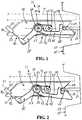
- FIG. 1is a side, partially broken view of an arrangement comprising a latch assembly according to an embodiment of the present invention showing the latch assembly in a closed position;
- FIG. 2is a side, partially broken view of the arrangement of FIG. 1 showing the latch assembly in an open position;
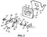
- FIG. 3is a perspective, exploded view of the arrangement of FIG. 1 ;
- FIG. 4Ais a side view of a latch assembly according to an embodiment of the present invention
- FIG. 4Bis a side view of a latch assembly according to another embodiment of the present invention.
- FIG. 5is a side view of a latch assembly according to still another embodiment of the present invention.
- FIGS. 1 and 2An arrangement 21 comprising a latch assembly 23 is shown in FIGS. 1 and 2 .
- the arrangementcomprises a first assembly 25 comprising a surface 27 such as a wall and, extending relative to the surface, a connecting bar 29 .
- the connecting bar 29may be in any suitable form, such as in the form of a U-shaped member as illustrated in FIG. 3 or in the form of a striker pin.
- the connecting bar 29can extend from a member 30 ( FIG. 3 ) that is secured inside of the wall 27 and is substantially concealed by a member such as the member that is referred to here as a bezel 31 .
- the bezel 31comprises an opening 33 through which the connecting bar extends, an outer surface 35 , and a recess 37 in the outer surface in which the opening is disposed.
- the connecting bar 29may extend past the outer surface 35 of the bezel 31 but, ordinarily, will not so that it does not project into an area proximate the wall 27 and present a hazard.
- the recess 37can be formed with walls shaped to help guide an entering latch assembly 23 toward the connecting bar 29 , such as by sloping inwardly in a direction away from the surface 35 .
- the connecting bar 29may be a rigid bar or a flexible member such as a cable, and can take any suitable form, such as having a U-shape or being a straight member, and such as being circular in shape as shown or having some other shape, such as the shape of a plate.
- the arrangement 21also comprises a second assembly 39 comprising a surface 41 (shown in phantom) and the latch assembly 23 including a plate 43 attached to the surface.
- the surface 41may be any number of structures, such as a table top, a bunk, a chair, a cabinet, to name but a few.
- the plate 43may be attached to the surface 41 in any suitable manner, such as by bolts extending through a flanged portion of the plate.
- the latch assembly 23also comprises an arm 45 pivotable between a closed position ( FIG. 1 ) and an open position ( FIG. 2 ) relative to the plate 43 about a pivot axis 47 .
- the plate 43and the surface 41 attached to the plate, can also be considered to pivot about the pivot axis 47 relative to the arm 45 .
- the pivot axis 47is substantially aligned with a line of entry 49 of the connecting bar 29 to a latched position in which, when the arm 45 is in the closed position, the connecting bar is entirely surrounded by both the plate 43 and the arm together and partially surrounded by the arm and the plate individually.
- the arm 45can extend parallel to the line of entry 49 when the arm is in the closed position.
- the plate 43is fixed relative to the line of entry 49 although the plate, to which the surface is attached, might alternatively be pivotable and the arm can be fixed relative to the line of entry.
- the latch-assembly 23can include latch assemblies wherein dimensions of the latch assembly can be minimized as compared to latch assemblies wherein one or more components individually include material surrounding a connecting bar by 360°. By minimizing latch assembly dimensions, it is possible to minimize the size of any recess for a connecting bar in any structure to be latched to a structure to which the latch assembly is connected.
- a “latch assembly” in the sense used in the present applicationcomprises a plate and an arm.
- the structure comprising the latch assemblymay comprise, but does not necessarily also comprise, components that typically are sold together with the plate and the arm, such as a connecting bar, a table, a cabinet, a bunk, a truck cab, or a truck.
- “Line of entry” in the sense used in the present applicationis intended to refer to the line along which the connecting bar 29 travels from the point at which the arm 45 is pivoted to the fully open position as shown in FIG. 2 to the point at which the arm 45 is pivoted to the closed position as shown in FIG. 1 , as when the connecting bar is in the latched position.
- the latch assembly 23 shown in FIGS. 1 and 2comprises a stop 51 arranged to stop the arm 45 in the closed position.
- the stop 51can be in any suitable form.
- the stop 51 shown in FIGS. 1 and 2comprises a cylinder 53 bolted to the plate 43 by a bolt 55 .
- a similar cylinder 57is bolted to the plate 43 by a bolt 59 to define a pivot assembly centered around the pivot axis 47 .
- the arm 45includes an opening 61 ( FIG. 3 ) in which the cylinder 57 of the pivot assembly is disposed.
- the cylinders 53 and 57can be used to facilitate mounting of a cover plate 63 ( FIG. 3 ) at a suitable spacing from the plate 43 .
- the stop 51is substantially aligned with the line of entry 49 .
- the stopmay be disposed elsewhere, however, aligning the stop 51 with the line of entry 49 facilitates minimizing the dimensions of the latch assembly 23 .
- the arm 45is typically formed with a notch 65 for receiving the connecting bar 29 at a point remote from the pivot axis 47 .
- the notch 65can be substantially aligned with the line of entry 49 , which will ordinarily aid in keeping the size of the latch assembly 23 to a minimum.
- the arm 45can be formed with a recessed area 67 between the pivot axis 47 and the notch 65 where the stop 51 is intended to contact the arm. In this way, the combined thickness of the arm 45 and the stop 51 does not make the latch assembly 23 unnecessarily large.
- a forward surface 69 of the plate 43 and a forward surface 71 of the arm 45can be sloped or otherwise arranged to define a V-shape when the arm is in the closed position.
- the V-shapecan facilitate guiding of the connector bar 29 from an unlatched position to the latched position.
- the centerline of the V-shapecan be substantially parallel to the line of entry 49 .
- the arm 45automatically tends to move to the closed position. This can be accomplished by the arm 45 being arranged so that a force such as gravity causes the arm to pivot about the pivot axis 47 to the closed position.
- a second arm 175can extend from a pivot axis 147 of an arm 145 and be weighted by a mass M so that gravity will cause the arm to pivot upwardly to the closed position; or, as shown in FIG. 4B , the arm 245 can be arranged so that it pivots downwardly to a closed position.
- some form of non-gravity means for causing the arm to move to the closed positionwill be provided. As seen in FIGS.
- a spring 77such as a torsion spring can be arranged to move the arm 45 to the closed position.
- a spring 77such as a torsion spring can be arranged to move the arm 45 to the closed position.
- other resilient spring devicescan be used, such as compression or tension springs, compressible rubber members, and the like.
- Yet another possible non-gravity means for causing an arm 345 to move to the closed positionis seen in FIG. 5 and is in the form of a magnet 377 , which may be a permanent magnet or an electro-magnet that attracts a ferromagnetic arm or a magnet mounted on an arm.
- the armmay also be moved manually between a closed and an open position, if desired.
- the arm 45can form part of a lever, the lever comprising a second arm 75 extending from proximate the pivot axis 47 .
- the second arm 75can extend substantially parallel to the arm 45 , although FIGS. 1 and 2 show the arm extending at a non-zero angle relative to the arm and relative to the line of entry 49 . Having the second arm 75 extend at a non-zero angle relative to the arm 45 and the line of entry 49 can be useful to, inter alia, facilitate activating the arm so that it moves from the closed to the open position.
- An activating member 81can be attached to the arm 45 or the second arm 75 and arranged such that application of a force upon the activating member tends to move the arm to the open position.
- the activating member 81 in FIGS. 1 and 2is in the form of a cable 83 including an enlarged portion 85 that can be attached to the plate 43 , such as in a notch 86 , to keep the cable in a desired location.
- the activating member 81can also function as a stop to limit pivoting of the arm 45 relative to the plate 43 . By pulling on the cable 83 , the activating member 81 will cause the arm 45 to pivot from a closed position ( FIG. 1 ) to an open position ( FIG. 2 ).
- activating membersin the form of flexible members such as cables
- rigid activating memberssuch as the rod 87 shown in phantom in FIG. 2
- the activating memberneed not extend in or substantially in the plane of the arm 45 as with the illustrated cable 83 and rod 87 and may, for example, be in the form of a member extending perpendicular to the arm and upon which a user can supply a force to cause the arm to move from the closed to the open position.
Landscapes
- Engineering & Computer Science (AREA)
- Mechanical Engineering (AREA)
- Lock And Its Accessories (AREA)
Abstract
Description
Claims (23)
Applications Claiming Priority (1)
| Application Number | Priority Date | Filing Date | Title |
|---|---|---|---|
| PCT/US2005/017637WO2006126985A1 (en) | 2005-05-20 | 2005-05-20 | Latch assembly and arrangement including a latch assembly |
Publications (2)
| Publication Number | Publication Date |
|---|---|
| US20080224480A1 US20080224480A1 (en) | 2008-09-18 |
| US7959194B2true US7959194B2 (en) | 2011-06-14 |
Family
ID=37452303
Family Applications (1)
| Application Number | Title | Priority Date | Filing Date |
|---|---|---|---|
| US11/911,854Expired - Fee RelatedUS7959194B2 (en) | 2005-05-20 | 2005-05-20 | Latch assembly and arrangement including a latch assembly |
Country Status (2)
| Country | Link |
|---|---|
| US (1) | US7959194B2 (en) |
| WO (1) | WO2006126985A1 (en) |
Cited By (30)
| Publication number | Priority date | Publication date | Assignee | Title |
|---|---|---|---|---|
| US20100139338A1 (en)* | 2007-07-25 | 2010-06-10 | Hans-Peter Wintersteiger | Lock which can be unlocked in an electrically automated manner, in particular for storage systems like lockers |
| US20160114889A1 (en)* | 2014-10-27 | 2016-04-28 | C&D Zodiac, Inc. | Overhead storage bin latch system |
| USD828029S1 (en) | 2017-06-12 | 2018-09-11 | Yeti Coolers, Llc | Container |
| USD828028S1 (en) | 2017-06-12 | 2018-09-11 | Yeti Coolers, Llc | Container |
| USD838983S1 (en) | 2017-06-12 | 2019-01-29 | Yeti Coolers, Llc | Container |
| USD838984S1 (en) | 2017-06-12 | 2019-01-29 | Yeti Coolers, Llc | Container |
| USD840150S1 (en) | 2017-06-12 | 2019-02-12 | Yeti Coolers, Llc | Container |
| US10258219B2 (en)* | 2013-04-05 | 2019-04-16 | Arcelik Anonim Sirketi | Household appliance comprising a lock |
| US10443278B1 (en)* | 2019-03-14 | 2019-10-15 | John C. Moody | Gate lifter latch |
| USD869160S1 (en) | 2017-06-12 | 2019-12-10 | Yeti Coolers, Llc | Container |
| USD872478S1 (en) | 2017-06-12 | 2020-01-14 | Yeti Coolers, Llc | Container |
| USD872485S1 (en) | 2017-06-12 | 2020-01-14 | Yeti Coolers, Llc | Container |
| USD873020S1 (en) | 2017-06-12 | 2020-01-21 | Yeti Coolers, Llc | Container |
| USD904829S1 (en) | 2018-12-11 | 2020-12-15 | Yeti Coolers, Llc | Container accessories |
| USD907445S1 (en) | 2018-12-11 | 2021-01-12 | Yeti Coolers, Llc | Container accessories |
| US11203465B2 (en) | 2017-06-12 | 2021-12-21 | Yeti Coolers, Llc | Container and latching system |
| USD946894S1 (en) | 2017-06-12 | 2022-03-29 | Yeti Coolers, Llc | Container |
| USD951643S1 (en) | 2020-06-30 | 2022-05-17 | Yeti Coolers, Llc | Luggage |
| USD954436S1 (en) | 2020-06-30 | 2022-06-14 | Yeti Coolers, Llc | Luggage |
| USD960648S1 (en) | 2020-12-16 | 2022-08-16 | Yeti Coolers, Llc | Container accessory |
| USD961926S1 (en) | 2020-06-30 | 2022-08-30 | Yeti Coolers, Llc | Luggage |
| USD963344S1 (en) | 2020-06-30 | 2022-09-13 | Yeti Coolers, Llc | Luggage |
| US20220333416A1 (en)* | 2019-09-12 | 2022-10-20 | Southco, Inc. | Rotary latch assembly with multiple striker engagements |
| US11517086B2 (en) | 2019-01-06 | 2022-12-06 | Yeti Coolers, Llc | Luggage system |
| USD985937S1 (en) | 2020-12-16 | 2023-05-16 | Yeti Coolers, Llc | Container |
| US11685573B2 (en) | 2017-06-12 | 2023-06-27 | Yeti Coolers, Llc | Carry strap for container |
| USD994438S1 (en) | 2020-12-16 | 2023-08-08 | Yeti Coolers, Llc | Container |
| US11976498B2 (en) | 2017-06-12 | 2024-05-07 | Yeti Coolers, Llc | Container and latching system |
| US12108853B2 (en) | 2019-01-06 | 2024-10-08 | Yeti Coolers, Llc | Luggage system |
| US12225993B2 (en) | 2019-01-06 | 2025-02-18 | Yeti Coolers, Llc | Luggage system |
Families Citing this family (3)
| Publication number | Priority date | Publication date | Assignee | Title |
|---|---|---|---|---|
| GB2513883A (en)* | 2013-05-08 | 2014-11-12 | Weston Body Hardware Ltd | Compression Latch |
| US20170321454A1 (en)* | 2016-05-03 | 2017-11-09 | Joshua Steven Siebert | Gravity Gate Latch |
| US10385597B2 (en) | 2016-05-03 | 2019-08-20 | Joshua Steven Siebert | Gravity gate latch lockable and unlockable by a padlock from both sides of a gate |
Citations (37)
| Publication number | Priority date | Publication date | Assignee | Title |
|---|---|---|---|---|
| US1002259A (en)* | 1911-03-17 | 1911-09-05 | Frederick W Goedeke | Spring-lock for boxes and other receptacles. |
| US1016422A (en)* | 1911-04-13 | 1912-02-06 | Bertran Lauritsen | Latch for sliding doors. |
| US1133254A (en) | 1912-07-26 | 1915-03-30 | Henry N Backus | Crate-lock. |
| US1155953A (en)* | 1915-04-16 | 1915-10-05 | William Bryan Morrow | Screen-door fastener. |
| US1762883A (en)* | 1928-12-03 | 1930-06-10 | Norman William | Door catch |
| US1830786A (en)* | 1929-12-30 | 1931-11-10 | Frantz Mfg Co | Latch |
| US2246787A (en) | 1940-05-23 | 1941-06-24 | Houdaille Hershey Corp | Latch structure |
| US2288926A (en)* | 1941-03-12 | 1942-07-07 | Spencer R Strader | Tailgate latch |
| US2517185A (en)* | 1947-09-11 | 1950-08-01 | Morgan S Elmer | Lock |
| US3433518A (en)* | 1967-03-16 | 1969-03-18 | Lawrence Brothers | Latch assembly |
| US3463530A (en)* | 1968-02-16 | 1969-08-26 | Edward S Modes | Screen door latch |
| US3620560A (en) | 1969-10-02 | 1971-11-16 | Gen Motors Corp | Vehicle closure latch |
| US4005898A (en) | 1975-03-18 | 1977-02-01 | Way Lee V | Convertible seat/bed structure and associated foldable table for pickup trucks and the like |
| US4273368A (en) | 1979-07-06 | 1981-06-16 | American Safety Equipment Corporaion | Dual latching mechanism for a flexible deck lid |
| US4690440A (en)* | 1985-12-30 | 1987-09-01 | Rogers Gerald H | Strengthened latch and striker bar structure for fence gates |
| JPH01219272A (en) | 1988-02-26 | 1989-09-01 | Yoshio Shimizu | Lock for sliding door |
| US4871203A (en)* | 1988-01-04 | 1989-10-03 | J & J Hardware, Inc. | Reversible mount gate latch with manual latch locking |
| US4887854A (en)* | 1988-04-19 | 1989-12-19 | Fence Hardware Specialties, Inc. | Gate support latch |
| USD320545S (en)* | 1989-02-02 | 1991-10-08 | Sciarrino Joseph T | Alarmed latch assembly for a sliding door |
| US5209530A (en)* | 1992-09-02 | 1993-05-11 | A. L. Hansen Mfg. Co. | Latch |
| US5358292A (en)* | 1992-03-12 | 1994-10-25 | Wiebe Peter C Van | Gate latch |
| US5432963A (en) | 1993-01-12 | 1995-07-18 | Asc Incorporated | Truck cab mattress |
| US5655801A (en)* | 1995-09-21 | 1997-08-12 | Casey; Michael | Gate latch |
| JPH10238187A (en) | 1997-02-27 | 1998-09-08 | Sanpou Lock Co Ltd | Push-pull lock for sliding door |
| US5984404A (en) | 1997-02-25 | 1999-11-16 | Freightliner Corporation | Vehicle with bed raising and lowering system |
| US6092845A (en)* | 1997-01-17 | 2000-07-25 | Dura Automotive Systems, Inc. | Hood latch and release mechanism and operating system including same |
| US6422626B1 (en) | 1999-11-18 | 2002-07-23 | International Truck And Engine Corporation Canada | Interior expandable wardrobe for truck cabs |
| US6485071B2 (en)* | 2001-01-26 | 2002-11-26 | Midway Products Group, Inc. | Latch for vehicle closure member |
| US6578905B1 (en) | 2002-05-08 | 2003-06-17 | International Truck Intellectual Property Company, L.L.C. | Vehicle sleeper compartment bunk bed ladder |
| US6591554B2 (en) | 2001-06-13 | 2003-07-15 | John M. Kumer, Jr. | Floor mounted flush folding device |
| US6659516B2 (en)* | 2001-01-05 | 2003-12-09 | Apple Computer, Inc. | Locking system for a portable computer |
| US6682129B2 (en) | 2002-06-24 | 2004-01-27 | International Truck Intellectual Property Company, Llc | Flare module truck sleeper cab assembly |
| US6735797B1 (en) | 2000-11-24 | 2004-05-18 | L&P Property Management Company | Adjustable bed system |
| US6808080B2 (en)* | 2002-03-08 | 2004-10-26 | Delaware Capital Formation, Inc. | Container latching method and apparatus |
| US20060012184A1 (en)* | 2004-07-19 | 2006-01-19 | Kenneth Ottesen | Gaming machine lid/door latch |
| US7032939B2 (en)* | 2003-05-08 | 2006-04-25 | Southco, Inc. | Lock |
| US7405927B2 (en)* | 2004-09-10 | 2008-07-29 | Hewlett-Packard Development Company, L.P. | Push-button latching mechanism |
- 2005
- 2005-05-20USUS11/911,854patent/US7959194B2/ennot_activeExpired - Fee Related
- 2005-05-20WOPCT/US2005/017637patent/WO2006126985A1/enactiveApplication Filing
Patent Citations (37)
| Publication number | Priority date | Publication date | Assignee | Title |
|---|---|---|---|---|
| US1002259A (en)* | 1911-03-17 | 1911-09-05 | Frederick W Goedeke | Spring-lock for boxes and other receptacles. |
| US1016422A (en)* | 1911-04-13 | 1912-02-06 | Bertran Lauritsen | Latch for sliding doors. |
| US1133254A (en) | 1912-07-26 | 1915-03-30 | Henry N Backus | Crate-lock. |
| US1155953A (en)* | 1915-04-16 | 1915-10-05 | William Bryan Morrow | Screen-door fastener. |
| US1762883A (en)* | 1928-12-03 | 1930-06-10 | Norman William | Door catch |
| US1830786A (en)* | 1929-12-30 | 1931-11-10 | Frantz Mfg Co | Latch |
| US2246787A (en) | 1940-05-23 | 1941-06-24 | Houdaille Hershey Corp | Latch structure |
| US2288926A (en)* | 1941-03-12 | 1942-07-07 | Spencer R Strader | Tailgate latch |
| US2517185A (en)* | 1947-09-11 | 1950-08-01 | Morgan S Elmer | Lock |
| US3433518A (en)* | 1967-03-16 | 1969-03-18 | Lawrence Brothers | Latch assembly |
| US3463530A (en)* | 1968-02-16 | 1969-08-26 | Edward S Modes | Screen door latch |
| US3620560A (en) | 1969-10-02 | 1971-11-16 | Gen Motors Corp | Vehicle closure latch |
| US4005898A (en) | 1975-03-18 | 1977-02-01 | Way Lee V | Convertible seat/bed structure and associated foldable table for pickup trucks and the like |
| US4273368A (en) | 1979-07-06 | 1981-06-16 | American Safety Equipment Corporaion | Dual latching mechanism for a flexible deck lid |
| US4690440A (en)* | 1985-12-30 | 1987-09-01 | Rogers Gerald H | Strengthened latch and striker bar structure for fence gates |
| US4871203A (en)* | 1988-01-04 | 1989-10-03 | J & J Hardware, Inc. | Reversible mount gate latch with manual latch locking |
| JPH01219272A (en) | 1988-02-26 | 1989-09-01 | Yoshio Shimizu | Lock for sliding door |
| US4887854A (en)* | 1988-04-19 | 1989-12-19 | Fence Hardware Specialties, Inc. | Gate support latch |
| USD320545S (en)* | 1989-02-02 | 1991-10-08 | Sciarrino Joseph T | Alarmed latch assembly for a sliding door |
| US5358292A (en)* | 1992-03-12 | 1994-10-25 | Wiebe Peter C Van | Gate latch |
| US5209530A (en)* | 1992-09-02 | 1993-05-11 | A. L. Hansen Mfg. Co. | Latch |
| US5432963A (en) | 1993-01-12 | 1995-07-18 | Asc Incorporated | Truck cab mattress |
| US5655801A (en)* | 1995-09-21 | 1997-08-12 | Casey; Michael | Gate latch |
| US6092845A (en)* | 1997-01-17 | 2000-07-25 | Dura Automotive Systems, Inc. | Hood latch and release mechanism and operating system including same |
| US5984404A (en) | 1997-02-25 | 1999-11-16 | Freightliner Corporation | Vehicle with bed raising and lowering system |
| JPH10238187A (en) | 1997-02-27 | 1998-09-08 | Sanpou Lock Co Ltd | Push-pull lock for sliding door |
| US6422626B1 (en) | 1999-11-18 | 2002-07-23 | International Truck And Engine Corporation Canada | Interior expandable wardrobe for truck cabs |
| US6735797B1 (en) | 2000-11-24 | 2004-05-18 | L&P Property Management Company | Adjustable bed system |
| US6659516B2 (en)* | 2001-01-05 | 2003-12-09 | Apple Computer, Inc. | Locking system for a portable computer |
| US6485071B2 (en)* | 2001-01-26 | 2002-11-26 | Midway Products Group, Inc. | Latch for vehicle closure member |
| US6591554B2 (en) | 2001-06-13 | 2003-07-15 | John M. Kumer, Jr. | Floor mounted flush folding device |
| US6808080B2 (en)* | 2002-03-08 | 2004-10-26 | Delaware Capital Formation, Inc. | Container latching method and apparatus |
| US6578905B1 (en) | 2002-05-08 | 2003-06-17 | International Truck Intellectual Property Company, L.L.C. | Vehicle sleeper compartment bunk bed ladder |
| US6682129B2 (en) | 2002-06-24 | 2004-01-27 | International Truck Intellectual Property Company, Llc | Flare module truck sleeper cab assembly |
| US7032939B2 (en)* | 2003-05-08 | 2006-04-25 | Southco, Inc. | Lock |
| US20060012184A1 (en)* | 2004-07-19 | 2006-01-19 | Kenneth Ottesen | Gaming machine lid/door latch |
| US7405927B2 (en)* | 2004-09-10 | 2008-07-29 | Hewlett-Packard Development Company, L.P. | Push-button latching mechanism |
Non-Patent Citations (3)
| Title |
|---|
| International Search Report for corresponding International Application PCT/US2005/017637. |
| Patent Abstracts of Japan for JP 01-219272, published Sep. 1, 1989, applicant Shimizu Yoshio. |
| Patent Abstracts of Japan for JP 10-238187, published Sep. 8, 1998, applicant Sanpou Lock Co. Ltd. |
Cited By (47)
| Publication number | Priority date | Publication date | Assignee | Title |
|---|---|---|---|---|
| US8757677B2 (en)* | 2007-07-25 | 2014-06-24 | Keba Ag | Lock which can be unlocked in an electrically automated manner, in particular for storage systems like lockers |
| US20100139338A1 (en)* | 2007-07-25 | 2010-06-10 | Hans-Peter Wintersteiger | Lock which can be unlocked in an electrically automated manner, in particular for storage systems like lockers |
| US10258219B2 (en)* | 2013-04-05 | 2019-04-16 | Arcelik Anonim Sirketi | Household appliance comprising a lock |
| US20160114889A1 (en)* | 2014-10-27 | 2016-04-28 | C&D Zodiac, Inc. | Overhead storage bin latch system |
| US9499272B2 (en)* | 2014-10-27 | 2016-11-22 | C&D Zodiac, Inc. | Overhead storage bin latch system |
| USD946894S1 (en) | 2017-06-12 | 2022-03-29 | Yeti Coolers, Llc | Container |
| USD828029S1 (en) | 2017-06-12 | 2018-09-11 | Yeti Coolers, Llc | Container |
| USD838984S1 (en) | 2017-06-12 | 2019-01-29 | Yeti Coolers, Llc | Container |
| USD840150S1 (en) | 2017-06-12 | 2019-02-12 | Yeti Coolers, Llc | Container |
| USD828028S1 (en) | 2017-06-12 | 2018-09-11 | Yeti Coolers, Llc | Container |
| US11685573B2 (en) | 2017-06-12 | 2023-06-27 | Yeti Coolers, Llc | Carry strap for container |
| USD869160S1 (en) | 2017-06-12 | 2019-12-10 | Yeti Coolers, Llc | Container |
| USD872478S1 (en) | 2017-06-12 | 2020-01-14 | Yeti Coolers, Llc | Container |
| USD872485S1 (en) | 2017-06-12 | 2020-01-14 | Yeti Coolers, Llc | Container |
| USD873020S1 (en) | 2017-06-12 | 2020-01-21 | Yeti Coolers, Llc | Container |
| USD838983S1 (en) | 2017-06-12 | 2019-01-29 | Yeti Coolers, Llc | Container |
| US11976498B2 (en) | 2017-06-12 | 2024-05-07 | Yeti Coolers, Llc | Container and latching system |
| USD946279S1 (en) | 2017-06-12 | 2022-03-22 | Yeti Coolers, Llc | Container |
| US11203465B2 (en) | 2017-06-12 | 2021-12-21 | Yeti Coolers, Llc | Container and latching system |
| USD959208S1 (en) | 2018-12-11 | 2022-08-02 | Yeti Coolers, Llc | Caddy accessory |
| USD925991S1 (en) | 2018-12-11 | 2021-07-27 | Yeti Coolers, Llc | Container accessories |
| USD925299S1 (en) | 2018-12-11 | 2021-07-20 | Yeti Coolers, Llc | Container accessories |
| USD907445S1 (en) | 2018-12-11 | 2021-01-12 | Yeti Coolers, Llc | Container accessories |
| USD1033158S1 (en) | 2018-12-11 | 2024-07-02 | Yeti Coolers, Llc | Container accessories |
| USD904829S1 (en) | 2018-12-11 | 2020-12-15 | Yeti Coolers, Llc | Container accessories |
| USD960656S1 (en) | 2018-12-11 | 2022-08-16 | Yeti Coolers, Llc | Bag accessory |
| USD962010S1 (en) | 2018-12-11 | 2022-08-30 | Yeti Coolers, Llc | Divider accessory |
| USD929814S1 (en) | 2018-12-11 | 2021-09-07 | Yeti Coolers, Llc | Container accessories |
| US12108853B2 (en) | 2019-01-06 | 2024-10-08 | Yeti Coolers, Llc | Luggage system |
| US11517086B2 (en) | 2019-01-06 | 2022-12-06 | Yeti Coolers, Llc | Luggage system |
| US12225993B2 (en) | 2019-01-06 | 2025-02-18 | Yeti Coolers, Llc | Luggage system |
| US10443278B1 (en)* | 2019-03-14 | 2019-10-15 | John C. Moody | Gate lifter latch |
| US20220333416A1 (en)* | 2019-09-12 | 2022-10-20 | Southco, Inc. | Rotary latch assembly with multiple striker engagements |
| US12378802B2 (en)* | 2019-09-12 | 2025-08-05 | Southco, Inc. | Rotary latch assembly with multiple striker engagements |
| USD963344S1 (en) | 2020-06-30 | 2022-09-13 | Yeti Coolers, Llc | Luggage |
| USD961926S1 (en) | 2020-06-30 | 2022-08-30 | Yeti Coolers, Llc | Luggage |
| USD954436S1 (en) | 2020-06-30 | 2022-06-14 | Yeti Coolers, Llc | Luggage |
| USD951643S1 (en) | 2020-06-30 | 2022-05-17 | Yeti Coolers, Llc | Luggage |
| USD960648S1 (en) | 2020-12-16 | 2022-08-16 | Yeti Coolers, Llc | Container accessory |
| USD1014969S1 (en) | 2020-12-16 | 2024-02-20 | Yeti Coolers, Llc | Container |
| USD1014965S1 (en) | 2020-12-16 | 2024-02-20 | Yeti Coolers, Llc | Container |
| USD994438S1 (en) | 2020-12-16 | 2023-08-08 | Yeti Coolers, Llc | Container |
| USD1080202S1 (en) | 2020-12-16 | 2025-06-24 | Yeti Coolers, Llc | Container |
| USD1082440S1 (en) | 2020-12-16 | 2025-07-08 | Yeti Coolers, Llc | Container accessory |
| USD1085823S1 (en) | 2020-12-16 | 2025-07-29 | Yeti Coolers, Llc | Container |
| USD985937S1 (en) | 2020-12-16 | 2023-05-16 | Yeti Coolers, Llc | Container |
| USD1096326S1 (en) | 2020-12-16 | 2025-10-07 | Yeti Coolers, Llc | Container |
Also Published As
| Publication number | Publication date |
|---|---|
| US20080224480A1 (en) | 2008-09-18 |
| WO2006126985A1 (en) | 2006-11-30 |
Similar Documents
| Publication | Publication Date | Title |
|---|---|---|
| US7959194B2 (en) | Latch assembly and arrangement including a latch assembly | |
| US12221805B2 (en) | Dampening mechanism for touch bar exit device | |
| US20200199915A1 (en) | Overslam bumper for vehicle door latch | |
| US8733807B2 (en) | Self-adjusting striker assembly | |
| US5152559A (en) | Latching mechanism | |
| US8382171B2 (en) | Self-adjusting striker assembly | |
| US9297183B2 (en) | Self-adjusting striker assembly | |
| US4470626A (en) | Closure latch having an isolated striker | |
| US7168668B2 (en) | Damage resistant antenna mount | |
| US20110025074A1 (en) | Dual pawl glove box latch assembly | |
| US7070225B2 (en) | Industrial truck with a lateral frame opening and a frame-reinforcing door | |
| US20070114802A1 (en) | Door striker | |
| WO2006078721A2 (en) | Aircraft seat track system, apparatus and method | |
| US7025395B2 (en) | Latch assembly and striker | |
| US8763979B2 (en) | Vehicle seat latch having striker compliance in transverse directions | |
| US7597374B1 (en) | Hinge and catch assembly for motor vehicle endgate system | |
| KR100388094B1 (en) | Glass receipt fixing equipment of vehicle | |
| US20090212579A1 (en) | Striker with damper | |
| US6513193B1 (en) | Door check mechanism providing an infinite number of stable positions | |
| US11535168B2 (en) | Ladder-mounted storage system | |
| US11866189B2 (en) | Latching system with movable anti-shear mechanism | |
| EP1653026A2 (en) | Latch assembly | |
| US20080251305A1 (en) | Engine hood door including variable door handle | |
| JP6705618B2 (en) | Door shock absorber and seat | |
| US12123233B2 (en) | Rotary actuated slam latch system |
Legal Events
| Date | Code | Title | Description |
|---|---|---|---|
| AS | Assignment | Owner name:VOLVO TRUCKS NORTH AMERICA, INC., NORTH CAROLINA Free format text:ASSIGNMENT OF ASSIGNORS INTEREST;ASSIGNOR:MAHONEY, WILLIAM C.;REEL/FRAME:019980/0739 Effective date:20071017 | |
| AS | Assignment | Owner name:VOLVO GROUP NORTH AMERICA, LLC, NORTH CAROLINA Free format text:ASSIGNMENT OF ASSIGNORS INTEREST;ASSIGNOR:VOLVO GROUP NORTH AMERICA, INC.;REEL/FRAME:026221/0715 Effective date:20091217 Owner name:VCF, INC., NORTH CAROLINA Free format text:MERGER;ASSIGNOR:VOLVO TRUCKS NORTH AMERICA, INC.;REEL/FRAME:026220/0335 Effective date:20051222 Owner name:VOLVO GROUP NORTH AMERICA, INC., NORTH CAROLINA Free format text:CHANGE OF NAME;ASSIGNOR:VCF, INC.;REEL/FRAME:026221/0689 Effective date:20060109 | |
| STCF | Information on status: patent grant | Free format text:PATENTED CASE | |
| FPAY | Fee payment | Year of fee payment:4 | |
| FEPP | Fee payment procedure | Free format text:MAINTENANCE FEE REMINDER MAILED (ORIGINAL EVENT CODE: REM.); ENTITY STATUS OF PATENT OWNER: LARGE ENTITY | |
| LAPS | Lapse for failure to pay maintenance fees | Free format text:PATENT EXPIRED FOR FAILURE TO PAY MAINTENANCE FEES (ORIGINAL EVENT CODE: EXP.); ENTITY STATUS OF PATENT OWNER: LARGE ENTITY | |
| STCH | Information on status: patent discontinuation | Free format text:PATENT EXPIRED DUE TO NONPAYMENT OF MAINTENANCE FEES UNDER 37 CFR 1.362 | |
| FP | Lapsed due to failure to pay maintenance fee | Effective date:20190614 |