US7957833B2 - Asset localization identification and movement system and method - Google Patents
Asset localization identification and movement system and methodDownload PDFInfo
- Publication number
- US7957833B2 US7957833B2US11/890,350US89035007AUS7957833B2US 7957833 B2US7957833 B2US 7957833B2US 89035007 AUS89035007 AUS 89035007AUS 7957833 B2US7957833 B2US 7957833B2
- Authority
- US
- United States
- Prior art keywords
- asset
- location
- tag
- identification
- active
- Prior art date
- Legal status (The legal status is an assumption and is not a legal conclusion. Google has not performed a legal analysis and makes no representation as to the accuracy of the status listed.)
- Expired - Fee Related, expires
Links
Images


Classifications
- G—PHYSICS
- G06—COMPUTING OR CALCULATING; COUNTING
- G06Q—INFORMATION AND COMMUNICATION TECHNOLOGY [ICT] SPECIALLY ADAPTED FOR ADMINISTRATIVE, COMMERCIAL, FINANCIAL, MANAGERIAL OR SUPERVISORY PURPOSES; SYSTEMS OR METHODS SPECIALLY ADAPTED FOR ADMINISTRATIVE, COMMERCIAL, FINANCIAL, MANAGERIAL OR SUPERVISORY PURPOSES, NOT OTHERWISE PROVIDED FOR
- G06Q10/00—Administration; Management
- G06Q10/08—Logistics, e.g. warehousing, loading or distribution; Inventory or stock management
Definitions
- the present inventionrelates generally to systems and methods for wireless asset and personnel locating.
- RFID tags and barcodeshave been proposed for inventory control in a warehouse or logistics system, because of their low cost and ease of use, but they cannot be read at a distance, requiring physical proximity to read the tag and requiring a fork lift operator to exit the fork lift to operate the barcode reader and manually match the entry with the location.
- Location equipmentcan be relatively bulky and costly, too bulky and costly to be assigned one to one with every asset as some assets may be smaller than and cost less than the location equipment.
- One popular form of location equipment, GPSlacks the precision to locate an asset to a bin on a shelf and lacks coverage inside a building, particularly a building with a metal roof or other complex metal structure. Location equipment that is not associated and identified with a particular asset lacks a way to identify the asset being located without manual entry.
- the present inventionpertains to a system and method for identification and location of an asset by tracking the mover of the asset using an active location device located with the mover and identifying the asset using an identification reader located with the mover and a passive identification tag located with the asset.
- a single movermay move many assets.
- An assetis identified; the mover then moves the asset to a destination location, whereupon the mover and asset position are determined.
- the asset locationmay then be recorded in memory.
- the measurement of the destination locationmay be extended from the location measured by the active location device by using additional measurement devices, for example a forklift height sensor.
- the passive tag reader and active location devicemay be packaged together and may utilize common signaling to a central controller.
- a further embodimentutilizes RFID or barcode technology for the passive tag and may utilize near field positioning technology for the active location device.
- FIG. 1is an exemplary process flow diagram showing an asset identification, localization, and movement process in accordance with the present invention.
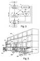
- FIG. 2is an exemplary schematic diagram describing one embodiment a system for identification, localization, and movement of an asset.
- FIG. 3is a process flow diagram showing an illustrative logistics process encompassing the asset identification, localization, and movement process of FIG. 1 .
- FIG. 4is a schematic diagram of an illustrative logistics facility.
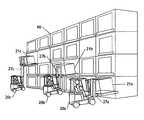
- FIG. 5is an exemplary schematic diagram describing forklifts placing assets at various levels in a rack.
- FIG. 6is a schematic diagram showing an exemplary embodiment asset and personnel localizing system involving a worker using a passive tag reader.
- FIG. 7is a functional block diagram showing an exemplary near field locator receiver for use in conjunction with an asset and personnel location, identification, and movement system.
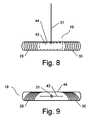
- FIG. 8is a mechanical diagram showing a side view of a locator receiver for use in conjunction with an asset and personnel location, identification, and movement system.
- FIG. 9is a mechanical diagram showing a top view of a locator receiver for use in conjunction with an asset and personnel location, identification, and movement system.
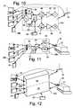
- FIG. 10is a functional block diagram showing an exemplary active location tag for use in conjunction with an asset and personnel location, identification, and movement system.
- FIG. 11is a functional block diagram showing an exemplary passive ID tag reader for use in conjunction with an asset and personnel location, identification, and movement system.
- FIG. 12is a block diagram showing interfaces for an exemplary LIDR for use in conjunction with an asset and personnel location, identification, and movement system.
- FIG. 13is a mechanical diagram showing an alternate embodiment active tag for use in conjunction with an asset and personnel location, identification, and movement system.
- the present inventionprovides a system for automated positioning of potentially thousands of items in a warehouse or other logistics staging operation by combining the best features of RFID or barcode tags with the capabilities of wireless active tracking devices to provide a low cost system for maintaining location awareness of every item in the warehouse.
- RFID tagsare typically low cost passive tags that can be excited by RF energy, typically from within a meter or so and respond by transmitting an ID number and potentially other status information.
- Barcode tagsinclude the familiar barcodes of the super market and include numerous standards and formats including two dimensional barcodes capable of high density information. Barcode tags are typically optical and are read optically. Numerous other similar techniques have been developed and are continually being developed for the numerous applications of these devices. Within this disclosure, these devices are collectively referred to as identification tags whether they are applied as tags or stick on labels or built into the asset, or otherwise associated with the asset. Identification tags are advantageous for their very low cost, low weight and small size.
- Wireless active tracking devicesare wireless devices that can track an object's movement and measure the object's position to sufficient accuracy to identify the position of the object within the correct bin or region in the storage area
- One such technology well suited to a warehouse environmentis near field positioning technology, near field positioning technology, typically utilizes multiple transmitters at known locations transmitting to a localizer receiver at the unknown location or multiple receivers at known locations receiving a signal from a transmitter at the unknown location.
- Other configurations and architecturesmay also be used.
- Near field electric and magnetic phase and amplitudesmay be compared to find range and position. Further details on near field position measurement may be found in U.S. Pat. No. 6,963,301 as well as the other applications which have been incorporated herein by reference above.
- Near field signalsappear to be resistant to disturbance from multipath and other effects typically found indoors. Thus, near field signals may offer advantages over higher frequency positioning systems. Further, near field signals offer convenient directional information when used with magnetic antennas, in particular, an orthogonally oriented pair of magnetic antennas. The directional information may be used to enhance location accuracy.
- Wireless positioning devicesare typically larger in size than RFID tags and require electrical power from batteries or plug in.
- the system of the present inventionapplies the advantages of low cost and small size of the ID tag to each asset, where low cost and small size are needed and incorporates the advantages of the wireless positioning system by placing the positioning system on the mover where the cost of the positioning system can be applied to a virtually countless number of assets by repeated usages.
- the benefits and shortcomings of the ID and positioning devicesare complementary—each device overcomes the shortcomings of the other device, enabling a system that would not be practical with either single device type alone.
- FIG. 1is an exemplary process flow diagram showing an asset identification, localization, and movement process in accordance with the present invention.
- the steps of FIG. 1may be performed in any order, as desired.
- the localization equipmentis installed on or otherwise associated with the mover, as is the ID reader.
- a low cost ID tagis attached or otherwise associated with the asset.
- the processmay begin with asset identification 10 a and may also optionally include asset localization 9 a .
- asset identification 10 atypically, a worker is instructed to move an asset to a new location within a warehouse. The worker first finds the asset by going to the last known location of the asset 9 a and looking for the asset according to an asset identification 10 a (typically a barcode number or RFID).
- asset identification 10 atypically a barcode number or RFID
- the assetWhen the asset is found, and identified 10 a , the asset is picked up and moved 11 to the new location. The new location may not be precisely identified until the worker arrives at the area and finds an empty spot. Upon placing the asset at the new location, the asset location is measured 9 b precisely and recorded in a database. The asset identification may then be optionally verified 10 b . In an alternative sequence, the asset may be identified 10 b at the time of final placement and localization 9 b . (Localization means measuring the location of the asset in coordinates meaningful to the facility.) Other sequences of localization and identification may be desirable for other scenarios. Thus, the localization and identification is accomplished without installing expensive active trackers on each asset.
- FIG. 2is an exemplary schematic diagram describing one embodiment a system for identification, localization, and movement of an asset.
- the embodiment of FIG. 2comprises a worker 18 , a forklift 20 , an active location tag 24 co-located with worker 18 , a localizing ID reader (LIDR) 25 , one or more locator receivers 19 , a computer 23 , and a passive ID tag 26 co-located with an asset 21 .
- the worker 18 with or without the vehiclee.g. forklift 20
- the LIDR 25is a device with both active location capability and passive ID tag reading capability housed in the same unit, thus eliminating issues relating to associating the ID tag reader with the location tag.
- An active location tag 24 co-located with worker 18works in conjunction with locator receiver 19 and computer 23 to localize worker 18 and thus associated asset 21 .
- a LIDR 25 co-located with forklift 20in conjunction with a locator receiver 19 and computer 23 , may also serve for localizing forklift 20 and associated asset 21 .
- the LIDR 25 and passive ID tag 26 co-located with asset 21cooperate to serve as identifying means for asset 21 .
- FIG. 2illustrates the possible use of both an active locator tag associated with the worker and a LIDR associated with the forklift, only one locator is necessary.
- the LIDRis mounted on the body of the forklift where the LIDR can sense tags on assets loaded at the lower position of the lift.
- the LIDRmay be located on the lift to be lifted up with the asset and positioned forward next to the asset to better represent the actual position of the asset.
- the active locator tag 24(associated with a movement agent, such as a worker 18 ) transmits a signal to one or more locator receivers 19 , as necessary to determine a location measurement
- a computer 23accepts data from at least one locator receiver 19 and determines the location of active tag 24 and, thus, the movement agent, such as a worker 18 . If asset localization process 9 a and/or 9 b is performed in conjunction with asset identification process 10 a and/or 10 b , then associated asset 21 becomes both localized and identified. By performing asset localization process 9 a and 9 b before and after asset movement process 11 , an accurate location for asset 21 may be maintained in computer 23 .
- asset identification process 10may be performed by an active locator tag 24 associated with the asset 21 (rather than the mover) transmitting a signal to a locator receiver 19 .
- the signalmay be modulated so as to uniquely identify asset 21 .
- a generic signalmay be transmitted at a unique frequency or at a unique time so as to uniquely identify asset 21 .
- a data interface 54 to active locator tag 24may allow active tag 24 to respond on command from computer 23 so as to uniquely identify asset 21 .
- asset identification process 10may be performed by a passive tag reader 28 associated in location with a movement agent, such as worker 18 .
- Physical association of the passive tag reader with the movement agentmay be by being carried by the worker or by being mounted on a forklift operated by the worker or other similar arrangement.
- Logical association of the active locator tag information with the passive ID tag reader informationmay be made possible by a data exchange or handshaking between passive ID tag reader 28 and active locator tag 24 , as each device will have a serial number identifying the device.
- passive ID tag reader 28may convey data to computer 23 intermediate active locator tag 24 , i.e., by sending data through active locator tag 28 , thus providing associated location and identification data for asset 21 .
- passive ID tag reader 28may provide identification data directly to computer 23 in conjunction with adequate identifying information pertinent to active tag 24 to enable computer 23 to associate a measured location of active tag 24 with identification information relevant to asset 21 .
- each devicemay separately communicate with the computer over the network, but the two devices may be defined or configured in software as being fixed to the same forklift.
- associationmay follow from co-locating functionality of passive tag reader 28 and active tag 24 in localizing ID reader, LIDR 25 .
- the LIDR 25is a single unit with active locator tag and passive ID tag reading capability.
- a worker 18 with co-located active tag 24 and transportation vehicle such as a forklift 20 with co-located LIDR 25may similarly be associated by a data exchange or handshaking between active tag 24 and LIDR 25 , the results of said data exchange or handshaking being conveyed to computer 23 .
- Passive tag reader 28reads a passive tag 26 associated with asset 21 .
- Passive tag 26may be a bar code, and RFID tag, an optical pattern tag, an alternate technology tag, or some combination of passive tag modalities.
- One combination of particular valueis a bar code or optical pattern combined with an RFID tag.
- Asset movement process 11comprises a movement agent acting so as to transport asset 21 .
- Typical movement agentsinclude, but are not limited to, a worker 18 either solo or in conjunction a transporter such as a hand truck, forklift 20 , pallet jack, crane, reach truck, side loader, order picker, or other material handler or lifter. Further benefits and features of the asset identification, localization, and movement process may be better understood with reference to an illustrative logistics process.
- FIG. 3is a process flow diagram showing an illustrative logistics process encompassing the asset identification, localization, and movement process of FIG. 1 . Each movement line indicated between two of the blocks may be performed in accordance with the identification, localization and movement process of the present invention.
- the illustrative logistics processis not intended to be a comprehensive or universally applicable description of all logistics processes. Rather, the illustrative logistics process of FIG. 3 is intended to illustrate the potential benefits of the asset identification, localization, and movement process in a logistics process.
- the illustrative logistics processbegins with start block 1 and proceeds with asset acceptance and receiving process 2 in which an asset in receiving, like asset 21 , is received and accepted.
- a critical aspect of asset acceptance and receiving process 2is a determination of where an asset in receiving should go next. If an asset in receiving has been mistakenly shipped, if paperwork accompanying an asset in receiving is flawed, or if some other significant problem is identified with an asset in receiving, then the illustrative logistics process may continue with a quarantine process 3 . If an asset in receiving is to be stored for sufficient time to justify placing an asset in receiving into inventory, then the illustrative logistics process continues with asset in inventory process 4 .
- the illustrative logistics processmay continue with a cross-dock transfer to an asset release and shipping process 7 . If an asset in receiving comprises sub-assets that require repackaging, subdivision, or recombination, then the illustrative logistics process may continue with asset break-out process 6 .
- the illustrative logistics processfurther comprises a quarantine process 3 .
- a quarantine process 3an asset in quarantine (like asset 21 ) is placed in secure storage because of some problem identified in paperwork, a mis-shipment, or other problem necessitating secure storage of an asset in quarantine. If the problem is satisfactorily resolved, the illustrative logistics process may continue with asset in inventory process 4 . Alternatively, if an asset in quarantine comprises sub-assets that require repackaging, subdivision, or recombination, then the illustrative logistics process may continue with asset break-out process 6 . Finally if an asset in quarantine is to be released, shipped, or returned to the point of origin, then the illustrative logistics process may continue with a cross-dock transfer to an asset release and shipping process 7 .
- the illustrative logistics processfurther comprises an asset in inventory process 4 .
- An asset in inventory process 4involves an asset (like asset 21 ) being stored, for instance, in a pallet rack (like pallet rack 66 ), or in a staging or other storage area. If an asset in inventory has been mistakenly shipped, if paperwork accompanying an asset in inventory is flawed, or if some other significant problem is identified with an asset in inventory, then the illustrative logistics process may continue with a quarantine process 3 . If an asset in inventory is to be released or shipped, then the illustrative logistics process may continue with an asset release and shipping process 7 . If an asset in inventory comprises sub-assets that require repackaging, subdivision, or recombination, then the illustrative logistics process may continue with asset break-out process 6 .
- An asset in inventorymay be subject to a periodic identification such as in asset identification process 10 . Further, an asset in inventory may be subject to a periodic localization such as in asset localization process 9 .
- the illustrative logistics processfurther comprises an asset break-out process 6 .
- Asset break-out process 6involves an asset in break-out (like asset 21 ) being divided into sub-assets and being repackaged, processed, sub-divided, and/or recombined so as to create new assets.
- an asset in break-outmay be a pallet comprising six particular goods requiring repackaging to go to six different destinations.
- One asset in break outmay be divided into multiple assets in break-out, multiple assets in break-out may be combined into a smaller number of assets in break-out, or more complicated combinations and divisions are possible.
- the illustrative logistics processmay continue with an asset release and shipping process 7 . If an asset in break-out has been mistakenly shipped, if paperwork accompanying an asset in break-out is flawed, or if some other significant problem is identified with an asset in break-out, then the illustrative logistics process may continue with a quarantine process 3 . If an asset in break-out is to be stored for sufficient time to justify placing an asset in receiving into inventory, then the illustrative logistics process continues with asset in inventory process 4 .
- the illustrative logistics processfurther comprises asset release and shipping process 7 .
- Asset release and shipping process 7involves an asset in shipping being processed for release and shipment. If an asset in shipping is shipped, then the illustrative logistics process terminates in end block 8 . If an asset in shipping has been mistakenly subjected to asset release and shipping process 7 , then the illustrative logistics process may continue with a quarantine process 3 in which the further disposition of an asset in shipping may be decided.
- FIG. 4is a schematic diagram of an illustrative logistics facility 50 .
- the illustrative logistics facility 50is not intended to be comprehensive and universally applicable to all logistics facilities. Rather, the illustrative logistics facility of FIG. 4 is intended to illustrate the benefits of the asset identification, localization, and movement process in a typical logistics facility, either stand-alone or as a department in a larger business or other enterprise.
- the illustrative logistics facility 50comprises an acceptance and receiving area 12 , inventory area 14 , quarantine zone 13 , break-out area 16 , and release and shipping area 17 .
- the illustrative logistics facility 50further includes assets (like asset 21 ), workers (like worker 18 ), forklifts (like forklift 20 ), hand trucks (like hand truck 15 ), locator receivers (like locator receiver 19 ), pallet racks (like pallet rack 66 ), and a computer (like computer 23 ).
- forklift 20picks up asset 21 from truck 22 .
- a LIDR 25 co-located with forklift 20relays location and identification information via locator receiver 19 to computer 23 .
- Computer 23may send data to LIDR 25 to instruct worker 18 where to transport asset 21 .
- a LIDR 25 co-located with forklift 20relays location information via locator receiver 19 to computer 23 .
- a LIDR 25 co-located with forklift 20may further relay identification information via locator receiver 19 to computer 23 as a double-check or confirmation of the original identification when forklift 20 drops off asset 21 .
- a worker 18In asset break-out area 16 , a worker 18 is leaving with an asset 21 conveyed by a hand truck 15 .
- Worker 18identifies asset 21 by using passive tag reader 28 .
- Active tag 24co-located with worker 18 relays location information on worker 18 via locator receiver 19 to computer 23 .
- particularly valuable assetsmay warrant continuous monitoring and may have associated thereon a dedicated active location tag 24 , which may include identification information within the active location tag.
- a particularly valuable asset 21 with a co-located active location tag 24relays location information on worker 18 via locator receiver 19 to computer 23 .
- Active location tag 24may include an on board accelerometer 53 to detect motion and alert computer 23 via locator receiver 19 if motion occurs.
- a worker 18 entering quarantine area 13may be tracked to maintain a security log of those having entered quarantine area 13 or to ensure that only authorized workers (like worker 18 ) have entered quarantine area 13 .
- FIG. 5is an exemplary schematic diagram describing forklifts placing assets at various levels in a rack.
- Asset location in the vertical dimensionrequires additional location determination resources.
- locator receivers 19may be placed at the floor level and an additional set may be placed at the ceiling level to provide vertical received signal differences to resolve the vertical dimension.
- a set of locator receiversmay be placed in a plane with sufficient numbers to triangulate in three dimensions.
- dilution of precisionlimits the ability of the tracking system to determine elevation using location devices co-located in a common horizontal plane.
- elevation of an asset 21 in a pallet rack 66may be determined by sensing the forklift elevation with an elevation sensor.
- an elevation sensormay be coupled to the mechanical lift 27 for the forklift 20 .
- the elevation signalis then conveyed to the computer 23 either directly via the network or through the active location tag 24 or LIDR 25 associated with the forklift 20 .
- three forklifts 20 a - 20 care unloading three assets 21 a - 21 c into three different heights in pallet rack 66 .
- the respective fork lifting mechanisms 27 a - 27 care extended to different lengths as may be measured by a sensor coupled to the lift mechanism (sensor internal to mechanism 27 a - 27 c ).
- the extension dimensionsmay be sensed and added to the location determined from the localizer receivers to determine the asset location.
- a directionmust also be known.
- the active location tag signalmay be directional, indicating the horizontal orientation (azimuth) of the active location tag by using radio direction techniques.
- the azimuth of the active location tagis determined by a magnetic compass sensor. In another embodiment the azimuth is determined by radio direction signals.
- the location of the active location tag that is measured when the asset is placed in the destination locationmay be offset from the actual asset location. For example, if the active location tag is one meter back from the forks of the forklift, the position measured is actually in the aisle in front of the asset. However, the offset may be accommodated by noting that the forklift may be operated to consistently measure asset position from directly in front of each respective asset. Thus, each asset may be paired one to one with a corresponding location such that the corresponding locations for each asset are not ambiguous. Further, that a forklift returning to a measured location for a particular asset will be in position to load the identified asset even though the asset may actually be extended from the measured location.
- FIG. 6is a schematic diagram showing an exemplary embodiment asset and personnel localizing system involving a worker 18 using a passive tag reader 28 to identify an asset 21 .
- a first alternate embodiment system for identification, localization, and movement of an asset 21comprises a worker 18 , an active tag 24 co-located with worker 18 , a passive tag reader 28 , a locator receiver 19 , a computer 23 , and a passive tag 26 co-located with an asset 21 .
- An active tag 24 co-located with worker 18works in conjunction with locator receiver 19 and computer 23 to serve as localizing means, localizing worker 18 and thus associated asset 21 .
- a passive tag reader 28 and a passive tag 26 co-located with asset 21cooperate to serve as identifying means for asset 21 .
- the active location tag and locating receiver of the present inventionare based on transmitting and receiving near field signals.
- Location by near field signalsis fully described in the US patents and patent applications incorporated by reference above.
- near field signalsare signals received within a near field of the transmitter. The near field is best within 1 ⁇ 6 wavelength, but the effects may be utilized out to one wavelength or so.
- Near field signalsshow unique amplitude and phase changes with distance from the transmitter.
- E field and H field antennascouple in different ways to the signal with different amplitude decay profiles and different signal phase changes with distance. These amplitude and phase profiles may be used to measure distance.
- E field antennais typically a whip antenna and may be on the order of a meter in length for a 1 MHz signal.
- H field antennais typically a coil and may include a ferrite core. The H field antenna may be on the order of a few centimeters in length, width, and height.
- an often preferred configurationutilizes a magnetic antenna (H field antenna) for the mobile beacon transmitter (active location tag) and a vertically polarized E field antenna with two orthogonally oriented H field antennas for each of the fixed receiver locations.
- the two H field antennashave the null axes in the horizontal plane.
- An exemplary signal set from this arrangementincludes:
- multiple determinations of rangemay be made from this configuration by making different comparisons between E field and H field amplitude and phase.
- a weighted average of available determinationsis used based on the strongest or most reliable signals from the set.
- receiversare positioned to allow triangulation based on multiple range measurements, i.e., to each location receiver from the active location tag. If height is desired, additional receivers may be deployed to improve the height resolution.
- the receiversmay be connected to a central computer for combining the measurements from all receivers to determine location. The connection may be by wired or wireless network or other methods as desired.
- the areamay be pre-measured to account for specific local propagation disturbances and to reduce errors from equipment variations.
- a calibration set of measurementsis made by placing an active location tag at known locations and measuring the signals and phases at all receivers.
- a finer grid, or set of grids, of locationsmay be generated from extrapolation and interpolation from the measured locations.
- an unknown locationis determined by transmitting from the unknown location and comparing the set of measured data from all receivers with the stored calibration data to find a location having the best match. Best match may be determined by summing absolute value of the differences between each respective signal from each receiver, the best match being the lowest sum. In the sum, amplitudes and phases may be scaled to have similar effect on the sum. Weak signals may be ignored.
- a locationis determined as the centroid of a region having an error value above a predetermined threshold.
- motion constraintssuch as walls and motion dynamics including momentum are used to improve position.
- FIG. 7is a functional block diagram showing an exemplary near field locator receiver 19 for use in conjunction with an asset and personnel location, identification, and movement system.
- locator receiver 19comprises a first magnetic antenna 29 , an electric antenna 31 , a second magnetic antenna 30 (collectively, “three antennas”), and locator receiver board 43 .
- Locator receiver board 43comprises first (pre-) amplifiers 32 , and first mixers 34 that mix RF signals from three antennas with a signal from first local oscillator 68 to yield intermediate frequency (IF) signals.
- Band pass filters 35 and second amplifiers 36convey IF signals to second mixers 37 that mix IF signals with a signal from a second local oscillator to yield baseband signals.
- Phase lock loops 38stabilize response, increase stability, and reduce noise of baseband signals.
- a microprocessor 40compares baseband signals to timing signals from clock 41 to measure phase differences between baseband signals.
- the signals E, H 1 , H 2 , EH 1 , and EH 2 as described above being E field and H field magnitudes and phasesare measured by the receiver.
- Microprocessor 40conveys results to computer 23 via data interface 42 .
- Data interface 42may be a wired or wireless data network capable of transferring data between microprocessor 40 and computer 23 .
- FIG. 8is a mechanical diagram showing a side view of a locator receiver 19 for use in conjunction with an asset and personnel location, identification, and movement system.
- Locator receiver 19comprises first magnetic antenna 29 , electric antenna 31 , second magnetic antenna 30 , locator receiver board 43 , and enclosure 44 .
- First magnetic antenna 29 and second magnetic antenna 30are arranged so as to have mutually orthogonal nulls oriented in the plane of the floor of the warehouse.
- FIG. 9is a mechanical diagram showing a top view of a locator receiver 19 for use in conjunction with an asset and personnel location, identification, and movement system.
- Locator receiver 19comprises first magnetic antenna 29 , electric antenna 31 , second magnetic antenna 30 , locator receiver board 43 , and enclosure 44 .
- First magnetic antenna 29 and second magnetic antenna 30are arranged so as to have mutually orthogonal nulls with null axes in the horizontal plane.
- FIG. 9shows the first magnetic antenna 29 and second magnetic antenna 30 as exemplary coils 29 and 30 respectively.
- FIG. 9further illustrates the exemplary coils 29 and 30 wound on the enclosure 44 which is used as a coil form 44 for coils 29 and 30 .
- FIG. 10is a functional block diagram showing an exemplary active location tag for use in conjunction with an asset and personnel location, identification, and movement system.
- Active location tag 24 acomprises a clock or frequency reference 50 , a microprocessor 45 , a data interface 54 , a navigation sensor and/or other sensors 53 , a first RF oscillator 46 , a second RF oscillator 47 , a first RF amplifier 48 , a second RF amplifier 49 , a first (I) magnetic antenna ( 52 ), and a second (Q) magnetic antenna ( 51 ), and, if provided, a lift position sensor 55 for a forklift.
- a data interface 54provides for data to be conveyed to or received from the computer 23 or other devices on the network, such as an LIDR 25 , a passive tag reader 28 , or another active location tag 24 b .
- the data interface 54may be a wireless data network such as ZigBee®, WiFi®, or other network or communication link.
- data interface 54may be a receive-only simplex link and signals generated by a first (I) magnetic antenna 52 and a second (Q) magnetic antenna 51 may be modulated to transmit data.
- the first RF amplifier 48 and the second RF amplifier 49have an input power of 50 mW so that active tag 24 is in compliance with FCC regulations Part 15.219.
- a first RF oscillator 46 , and a second RF oscillator 47are phase offset so as to yield a quadrature transmit signal with omni-directional properties, i.e., first magnetic antenna is driven 90 degrees out of phase with respect to second magnetic antenna Signals generated by a first (I) magnetic antenna 52 and a second (Q) magnetic antenna 51 cooperate to yield a near-field signal which may be detected by one or more locator receivers 19 to determine the location coordinates of the active location tag.
- the active location tagmay also include an optional navigation sensor 53 .
- the navigation sensormay include one or more of a magnetic compass, odometer, accelerometer, speedometer, gyro, turn sensor, or other devices that may assist the RF positioning system in determining a position or orientation. Navigation may be used to filter noisy RF position measurements, to dead reckon in locations with weak RF coverage, or to provide additional dimensions of measurement, such as azimuth orientation of the forklift.
- a motion sensorsuch as an accelerometer, may be used to detect motion related to unauthorized movement of assets.
- FIG. 11is a functional block diagram showing an exemplary passive ID tag reader 28 for use in conjunction with an asset and personnel location, identification, and movement system.
- Passive tag reader 28 acomprises data interface 56 , microprocessor 57 , transmitter 58 , and receiver 59 .
- a data interface 56provides for data to be conveyed to or received from a computer 23 or other devices on the network such as an LIDR 25 , another passive ID tag reader 28 b , or an active tag 24 .
- a data interface 54may be a wireless data network such as ZigBee®, WiFi®, or other network.
- the ID tag readeralso includes an operator switch to initiate an ID reading.
- the switchmay also initiate a location reading from the active location tag.
- the computerupon receipt of an ID reading by the computer 23 , the computer will initiate a location reading from the active location tag that is associated with the ID reader as set up in the computer software.
- Transmitter 58excites passive tag 26 and receiver 59 receives identifying information from passive tag 26 .
- passive ID tag 26combines a bar code and an RFID device.
- Passive tag reader 58uses a laser to read the bar code of passive tag 26 , and an RFID reader to receive data from an RFID chip embedded in passive tag 26 .
- optical pattern or other technologiesmay be incorporated in passive tag 26 .
- Passive tag readerstypically have a short operational range, thus the positioning of the mover together with the reading of the ID tag indicates the ID tag and associated asset are close to the location of the mover.
- the measurementsmay be made more accurate and repeatable.
- Passive tag reader 28 afurther includes user interface 67 .
- User interface 67can convey such information to worker 18 as a destination, status, or other information pertinent to asset 21 in particular and the logistics process in general.
- FIG. 12is a block diagram showing interfaces for an exemplary LIDR 25 for use in conjunction with an asset and personnel location, identification, and movement system.
- the LIDR 25 acombines the functionality of the active location tag 24 and passive ID tag reader 28 in a single device package.
- a LIDR 25may include data interfaces for data to be conveyed to or received from a computer 23 or other devices on the network such as another LIDR 25 , a passive ID tag reader 28 , or an active location tag 24 .
- a LIDR 25radiates a signal capable of being localized by a locator-receiver 19 .
- a LIDR 25also can interrogate passive tag 26 so as to acquire identification data pertinent to asset 21 .
- the LIDRmay be mounted on a moving vehicle such as a forklift, hand truck, pallet jack or other vehicle, or may be carried by a worker.
- Advantages of the LIDRinclude the fixed association of the active location tag and passive ID reader, the convenience of having both devices in one package, and the sharing of interface, battery and computer resources.
- FIG. 13is a mechanical diagram showing an alternate embodiment active tag 68 for use in conjunction with an asset and personnel location, identification, and movement system.
- Alternate embodiment active tag 68battery 61 , first magnetic antenna 51 comprising a plurality of hollow core magnetic antennas 63 , second (Q) magnetic antenna comprising an orthogonal hollow core magnetic antenna 52 , hanger 60 , power cord 62 , power jack 64 and power outlet cover holder 65 .
- Short magnetic antennas cylindrical cores with a small length to diameter ratiotend not to have an effective permeability ( ⁇ e ) much greater than ten no matter what the effective bulk permeability of the bulk core material (see for instance M. F. “Doug” DeMaw, Ferromagnetic Core Design & Application Handbook , Starkville, Miss.: MFJ Publishing Company, 1996, p. 41).
- the inventorshave discovered that if a core is relatively short (L/D ⁇ ⁇ 10) hollow cores (like those of hollow core magnetic antennas 63 ) yield performance comparable to those of analogous solid cores. Hollow cores are advantageous because of less material and therefore lower weight and less cost.
- hanger 60is preferentially relatively stiff and allows alternate embodiment active tag 68 to be substantially rigidly mounted on a rear-view mirror of a vehicle or other placement.
- the relative stiffness of hanger 60prevents alternate embodiment active tag 68 from substantial swinging that might impair stability or performance.
- Hanger 60makes alternate embodiment active tag 68 well-suited for use in conjunction with tracking rental or other vehicles or for tracking forklifts.
- Power cord 62 and jack 64cooperate to allow alternate embodiment active tag 68 to be plugged into a standard 12V (“cigarette lighter”) car power jack or other power outlet.
Landscapes
- Business, Economics & Management (AREA)
- Engineering & Computer Science (AREA)
- Economics (AREA)
- Marketing (AREA)
- Entrepreneurship & Innovation (AREA)
- Human Resources & Organizations (AREA)
- Development Economics (AREA)
- Operations Research (AREA)
- Quality & Reliability (AREA)
- Strategic Management (AREA)
- Tourism & Hospitality (AREA)
- Physics & Mathematics (AREA)
- General Business, Economics & Management (AREA)
- General Physics & Mathematics (AREA)
- Theoretical Computer Science (AREA)
Abstract
Description
Claims (23)
Priority Applications (3)
| Application Number | Priority Date | Filing Date | Title |
|---|---|---|---|
| US11/890,350US7957833B2 (en) | 2002-08-19 | 2007-08-06 | Asset localization identification and movement system and method |
| US13/153,640US8326451B2 (en) | 2002-08-19 | 2011-06-06 | Inventory control and method |
| US13/692,721US9285453B2 (en) | 2002-08-19 | 2012-12-03 | Method of near-field electromagnetic ranging and location |
Applications Claiming Priority (11)
| Application Number | Priority Date | Filing Date | Title |
|---|---|---|---|
| US40460202P | 2002-08-19 | 2002-08-19 | |
| US40460402P | 2002-08-19 | 2002-08-19 | |
| US10/355,612US6963301B2 (en) | 2002-08-19 | 2003-01-31 | System and method for near-field electromagnetic ranging |
| US10/958,165US7298314B2 (en) | 2002-08-19 | 2004-10-04 | Near field electromagnetic positioning system and method |
| US63777904P | 2004-12-21 | 2004-12-21 | |
| US11/215,699US7414571B2 (en) | 2002-08-19 | 2005-08-30 | Low frequency asset tag tracking system and method |
| US11/272,533US7307595B2 (en) | 2004-12-21 | 2005-11-10 | Near field location system and method |
| US11/473,595US7755552B2 (en) | 2004-12-21 | 2006-06-23 | Space efficient magnetic antenna system |
| US11/500,660US7538715B2 (en) | 2004-10-04 | 2006-08-08 | Electromagnetic location and display system and method |
| US84159806P | 2006-08-31 | 2006-08-31 | |
| US11/890,350US7957833B2 (en) | 2002-08-19 | 2007-08-06 | Asset localization identification and movement system and method |
Related Parent Applications (5)
| Application Number | Title | Priority Date | Filing Date |
|---|---|---|---|
| US11/215,699Continuation-In-PartUS7414571B2 (en) | 2002-08-19 | 2005-08-30 | Low frequency asset tag tracking system and method |
| US11/473,595Continuation-In-PartUS7755552B2 (en) | 2002-08-19 | 2006-06-23 | Space efficient magnetic antenna system |
| US11/500,660Continuation-In-PartUS7538715B2 (en) | 2002-08-19 | 2006-08-08 | Electromagnetic location and display system and method |
| US13/153,640Continuation-In-PartUS8326451B2 (en) | 2002-08-19 | 2011-06-06 | Inventory control and method |
| US13/692,721Continuation-In-PartUS9285453B2 (en) | 2002-08-19 | 2012-12-03 | Method of near-field electromagnetic ranging and location |
Related Child Applications (1)
| Application Number | Title | Priority Date | Filing Date |
|---|---|---|---|
| US13/153,640Continuation-In-PartUS8326451B2 (en) | 2002-08-19 | 2011-06-06 | Inventory control and method |
Publications (2)
| Publication Number | Publication Date |
|---|---|
| US20070282482A1 US20070282482A1 (en) | 2007-12-06 |
| US7957833B2true US7957833B2 (en) | 2011-06-07 |
Family
ID=38791339
Family Applications (1)
| Application Number | Title | Priority Date | Filing Date |
|---|---|---|---|
| US11/890,350Expired - Fee RelatedUS7957833B2 (en) | 2002-08-19 | 2007-08-06 | Asset localization identification and movement system and method |
Country Status (1)
| Country | Link |
|---|---|
| US (1) | US7957833B2 (en) |
Cited By (13)
| Publication number | Priority date | Publication date | Assignee | Title |
|---|---|---|---|---|
| US20110082812A1 (en)* | 2009-10-01 | 2011-04-07 | Abdul Hamid Salemizadeh | Package transport monitoring and analysis |
| US20110080257A1 (en)* | 2009-10-05 | 2011-04-07 | Ut Battelle Llc | Configurable display for signal activated device |
| US20110191025A1 (en)* | 2010-02-01 | 2011-08-04 | Kurt Maynard | Sensor unit system |
| US20120103247A1 (en)* | 2010-10-29 | 2012-05-03 | Jeff Sessums | Device and method for tool identification and tracking |
| WO2013121369A1 (en) | 2012-02-16 | 2013-08-22 | Alma Mater Studiorum - Universita' Di Bologna | Method and apparatus for estimating a distance and a location through near-field multi-frequency radio transmissions |
| US9070275B1 (en) | 2014-02-21 | 2015-06-30 | Gearn Holdings LLC | Mobile entity tracking and analysis system |
| US9227820B2 (en) | 2010-02-01 | 2016-01-05 | Trimble Navigation Limited | Sensor unit system |
| US9269255B2 (en) | 2010-02-01 | 2016-02-23 | Trimble Navigation Limited | Worksite proximity warning |
| US9547079B2 (en) | 2014-02-06 | 2017-01-17 | Fedex Corporate Services, Inc. | Object tracking method and system |
| US9723050B2 (en) | 2012-11-13 | 2017-08-01 | International Business Machines Corporation | Tag authentication and location verification service |
| US20190326954A1 (en)* | 2018-04-20 | 2019-10-24 | R. J. Reynolds Tobacco Company | Smart Packaging and Display System |
| US11840271B2 (en) | 2020-06-25 | 2023-12-12 | Rehrig Pacific Company | Pallet sled and delivery system |
| US12242916B2 (en) | 2017-11-17 | 2025-03-04 | Divine Logic, Inc. | Systems and methods for tracking items |
Families Citing this family (64)
| Publication number | Priority date | Publication date | Assignee | Title |
|---|---|---|---|---|
| US8018383B1 (en) | 2010-06-08 | 2011-09-13 | Q-Track Corporation | Method and apparatus for determining location using signals-of-opportunity |
| US7755486B2 (en)* | 2004-05-06 | 2010-07-13 | Savi Technology, Inc. | Expanded compatibility RFID tags |
| US7770792B2 (en)* | 2004-06-23 | 2010-08-10 | Sap Ag | Methods and systems for managing stock transportation |
| US7669763B2 (en)* | 2004-06-23 | 2010-03-02 | Sap Ag | Methods and system for managing stock |
| KR100740197B1 (en)* | 2005-02-18 | 2007-07-18 | 삼성전자주식회사 | Location recognition system and home server of home network using electronic tag |
| US8381982B2 (en)* | 2005-12-03 | 2013-02-26 | Sky-Trax, Inc. | Method and apparatus for managing and controlling manned and automated utility vehicles |
| EP1850267B1 (en)* | 2006-04-28 | 2011-11-30 | Semiconductor Energy Laboratory Co., Ltd. | Semiconductor device and position detecting method using the semiconductor device |
| US8081699B2 (en) | 2006-07-15 | 2011-12-20 | Kazimierz Siwiak | Wireless communication system and method with elliptically polarized radio frequency signals |
| FR2905493B1 (en)* | 2006-08-31 | 2008-12-05 | Nbg Id Soc Par Actions Simplif | AUTOMATED SYSTEM FOR REALIZING LOCALIZED INVENTORIES |
| US9536215B2 (en)* | 2007-03-13 | 2017-01-03 | Oracle International Corporation | Real-time and offline location tracking using passive RFID technologies |
| US8600840B2 (en)* | 2007-12-05 | 2013-12-03 | International Business Machines Corporation | Dynamic asset monitoring using electronic markers |
| US20090160646A1 (en)* | 2007-12-20 | 2009-06-25 | General Electric Company | System and method for monitoring and tracking inventories |
| US8565913B2 (en)* | 2008-02-01 | 2013-10-22 | Sky-Trax, Inc. | Apparatus and method for asset tracking |
| US8024003B2 (en)* | 2008-03-06 | 2011-09-20 | Qualcomm Incorporated | Methods and apparatus for supporting communications using antennas associated with different polarization directions |
| US8326249B2 (en)* | 2008-03-06 | 2012-12-04 | Qualcomm Incorporated | Methods and apparatus for supporting communications using a first polarization direction electrical antenna and a second polarization direction magnetic antenna |
| US20100222917A1 (en)* | 2008-09-25 | 2010-09-02 | Bohlig James W | System and Method for Tagging Products for Use in Identification of the Components Therein |
| US20100141378A1 (en)* | 2008-12-08 | 2010-06-10 | Electronics And Telecommunications Research Institute | Apparatus and method for identifying structure |
| US20100176922A1 (en)* | 2009-01-12 | 2010-07-15 | Paul John Schwab | Mobile radio frequency identification (rfid) reader system |
| ITNA20090055A1 (en)* | 2009-09-16 | 2009-12-16 | Francesco Maria Sacerdoti | LOCALIZATION SYSTEM OF OBJECTS IN A WAREHOUSE THROUGH THE USE OF INSTRUMENTED LIFT TRUCKS. |
| GB201013128D0 (en)* | 2009-09-24 | 2010-09-22 | Barloworld Handling Ltd | Maintence control system |
| GB2476232A (en)* | 2009-12-11 | 2011-06-22 | Robotics Ltd Const | Proximity monitoring |
| FI123770B (en) | 2010-04-22 | 2013-10-31 | Konecranes Oyj | A method for crane control and warehouse management |
| US8599011B2 (en) | 2010-07-30 | 2013-12-03 | Q-Track Corporation | Firefighter location and rescue equipment employing path comparison of mobile tags |
| DE102010042535A1 (en)* | 2010-10-15 | 2012-04-19 | Geisler-Tannhoff Ingenieur Gmbh | Portable barcode handheld scanner used in automobile industry, has location system that locates vehicle component based on transponder signal |
| US8561897B2 (en) | 2010-11-18 | 2013-10-22 | Sky-Trax, Inc. | Load tracking utilizing load identifying indicia and spatial discrimination |
| NZ718566A (en)* | 2010-11-19 | 2017-10-27 | Isolynx Llc | Associative object tracking systems and methods |
| US20120179585A1 (en)* | 2011-01-06 | 2012-07-12 | General Electric Company | Method and System for Laboratory Asset Identification and Management |
| EP2668623A2 (en)* | 2011-01-24 | 2013-12-04 | Sky-Trax, Inc. | Inferential load tracking |
| US9780435B2 (en) | 2011-12-05 | 2017-10-03 | Adasa Inc. | Aerial inventory antenna |
| US10846497B2 (en) | 2011-12-05 | 2020-11-24 | Adasa Inc. | Holonomic RFID reader |
| US10050330B2 (en) | 2011-12-05 | 2018-08-14 | Adasa Inc. | Aerial inventory antenna |
| US11093722B2 (en) | 2011-12-05 | 2021-08-17 | Adasa Inc. | Holonomic RFID reader |
| US10476130B2 (en) | 2011-12-05 | 2019-11-12 | Adasa Inc. | Aerial inventory antenna |
| US9747480B2 (en) | 2011-12-05 | 2017-08-29 | Adasa Inc. | RFID and robots for multichannel shopping |
| US8942897B2 (en)* | 2013-03-18 | 2015-01-27 | Cnh Industrial America Llc | System and method for determining a location of an unloaded unit of agricultural product and locating a desired unit of agricultural product |
| CN103235998A (en)* | 2013-04-17 | 2013-08-07 | 江苏太运集团有限公司 | Intelligent logistics and EPC (electronic product code) network sensing system |
| US9245160B2 (en)* | 2013-08-20 | 2016-01-26 | Qualcomm Technologies International, Ltd. | Method for setting up a beacon network inside a retail environment |
| US9344308B2 (en)* | 2014-02-17 | 2016-05-17 | Cornell University | System and method for signal generation |
| US20160034730A1 (en)* | 2014-07-31 | 2016-02-04 | Trimble Navigation Limited | Asset location on construction site |
| FR3027140B1 (en)* | 2014-10-13 | 2016-10-28 | Solystic | LOGISTICAL INSTALLATION WITH PACKAGE TRANSPORT SHUTTERS AND PORTABLE PACKAGE IDENTIFICATION EQUIPMENT |
| US10268939B2 (en)* | 2015-04-22 | 2019-04-23 | Arizona Board Of Regents On Behalf Of Arizona State University | Systems and methods for an automated, near real-time, and mobile identification and localization approach with a combination of battery-less identification marking technologies and pseudo range-free localization algorithms |
| US11033054B2 (en)* | 2015-07-24 | 2021-06-15 | Rai Strategic Holdings, Inc. | Radio-frequency identification (RFID) authentication system for aerosol delivery devices |
| SG11201803032RA (en)* | 2015-10-23 | 2018-05-30 | Sato Holdings Kk | Storage and retrieval management system, storage and retrieval management method, and program |
| US10940997B2 (en)* | 2015-10-23 | 2021-03-09 | Sato Holdings Kabushiki Kaisha | Movement path management system, movement path management method, and non-transitory computer-readable medium |
| US10949629B2 (en) | 2017-03-01 | 2021-03-16 | Stephen Gould Corporation | Real-time tracking of passive identification tags |
| EP3606847B1 (en) | 2017-04-03 | 2022-10-26 | Swisslog Logistics, Inc. | Automated manufacturing facility and methods |
| AU2018248330A1 (en)* | 2017-04-07 | 2019-10-31 | BXB Digital Pty Limited | Systems and methods for tracking promotions |
| NL2018767B1 (en)* | 2017-04-24 | 2018-11-05 | Kratu B V | Combination of a warehouse and a means of transport, such as a forklift |
| US10824904B2 (en) | 2017-05-02 | 2020-11-03 | BXB Digital Pty Limited | Systems and methods for pallet identification |
| US10832208B2 (en) | 2017-05-02 | 2020-11-10 | BXB Digital Pty Limited | Systems and methods for facility matching and localization |
| WO2018204912A1 (en) | 2017-05-05 | 2018-11-08 | BXB Digital Pty Limited | Pallet with tracking device |
| US10977460B2 (en) | 2017-08-21 | 2021-04-13 | BXB Digital Pty Limited | Systems and methods for pallet tracking using hub and spoke architecture |
| CN111712826B (en) | 2017-10-20 | 2022-07-08 | Bxb数码私人有限公司 | System and method for tracking cargo carriers |
| US11068545B2 (en) | 2017-11-17 | 2021-07-20 | Battelle Memorial Institute | Spatial identification of assets using n-dimensional asset identifiers |
| US10796846B2 (en)* | 2018-05-23 | 2020-10-06 | Matrix Design Group, Llc | Long range coil and power source for a magnetic field generator |
| JP7107762B2 (en)* | 2018-06-20 | 2022-07-27 | 東芝テック株式会社 | Communication device, communication method and program |
| DE102018131267A1 (en)* | 2018-12-07 | 2020-06-10 | Sick Ag | Goods transport system and method for removing dropped goods |
| US10816637B2 (en) | 2018-12-27 | 2020-10-27 | Chep Technology Pty Limited | Site matching for asset tracking |
| AU2020228607B2 (en) | 2019-02-25 | 2021-08-19 | BXB Digital Pty Limited | Smart physical closure in supply chain |
| CN111674800B (en)* | 2020-06-03 | 2021-07-09 | 灵动科技(北京)有限公司 | Intelligent warehousing technology for automatic driving system |
| DE102020119277A1 (en) | 2020-07-22 | 2022-01-27 | Koenig & Bauer Ag | Device and method for locating multiple means of production |
| US11822999B2 (en) | 2020-10-20 | 2023-11-21 | Stephen Gould Corporation | Controlled zone tracking system |
| US20240232799A1 (en)* | 2023-01-09 | 2024-07-11 | Steven Kruger | Methods, devices, and systems for improving material handler efficiency |
| JP2025029431A (en)* | 2023-08-21 | 2025-03-06 | 東芝テック株式会社 | Information processing device, information processing system, and program |
Citations (30)
| Publication number | Priority date | Publication date | Assignee | Title |
|---|---|---|---|---|
| US5260694A (en) | 1992-01-10 | 1993-11-09 | Ndc Automation, Inc. | Automatic article tracking system for manually operated delivery system |
| US5565858A (en) | 1994-09-14 | 1996-10-15 | Northrop Grumman Corporation | Electronic inventory system for stacked containers |
| US5725253A (en) | 1991-10-09 | 1998-03-10 | Kiwisoft Programs Limited | Identification system |
| US5774876A (en) | 1996-06-26 | 1998-06-30 | Par Government Systems Corporation | Managing assets with active electronic tags |
| US5780826A (en) | 1995-03-27 | 1998-07-14 | Toyo Umpanki Co., Ltd. | Container handling apparatus and management system |
| US20020008621A1 (en) | 2000-01-06 | 2002-01-24 | Isogon Corporation | Method and system for determining the inventory and location of assets |
| US6353406B1 (en)* | 1996-10-17 | 2002-03-05 | R.F. Technologies, Inc. | Dual mode tracking system |
| US6496806B1 (en)* | 1999-12-16 | 2002-12-17 | Samsys Technologies Inc. | Method and system for tracking clustered items |
| US6550674B1 (en) | 2002-08-23 | 2003-04-22 | Yoram Neumark | System for cataloging an inventory and method of use |
| US20030089771A1 (en)* | 2001-11-12 | 2003-05-15 | 3M Innovative Properties Company | Radio frequency identification systems for asset tracking |
| US20030148775A1 (en)* | 2002-02-07 | 2003-08-07 | Axel Spriestersbach | Integrating geographical contextual information into mobile enterprise applications |
| US20040010339A1 (en)* | 2002-07-15 | 2004-01-15 | Mountz Michael C. | Material handling system and method using mobile autonomous inventory trays and peer-to-peer communications |
| US20040070503A1 (en) | 2002-10-10 | 2004-04-15 | Brian Monahan | Flexible RFID antenna panel and system |
| US6724308B2 (en) | 2000-08-11 | 2004-04-20 | Escort Memory Systems | RFID tracking method and system |
| US6739507B2 (en) | 2001-10-04 | 2004-05-25 | Ford Motor Company | Method of automated rail loading of automotive vehicles |
| US20040102870A1 (en) | 2002-11-26 | 2004-05-27 | Andersen Scott Paul | RFID enabled paper rolls and system and method for tracking inventory |
| US6825766B2 (en) | 2001-12-21 | 2004-11-30 | Genei Industries, Inc. | Industrial data capture system including a choke point portal and tracking software for radio frequency identification of cargo |
| US20050065861A1 (en) | 2003-09-08 | 2005-03-24 | Gary Bann | Systems and methods for configuring a warehouse for tracking the location of items within a controlled area |
| US20050187836A1 (en) | 2001-03-02 | 2005-08-25 | Chris Wolfe | Method and apparatus for providing a proof of delivery verification for freight transportation systems |
| US20050195083A1 (en) | 2004-01-30 | 2005-09-08 | Guy Venture | Detector system for detecting the direction in which an item passes through a determined boundary zone |
| US20050234641A1 (en) | 2004-04-14 | 2005-10-20 | International Business Machines Corporation | In-transit package location tracking and reporting |
| US20050240317A1 (en) | 2004-04-16 | 2005-10-27 | Kienzle-Lietl Kathleen G | Material transport in-motion product dimensioning system and method |
| US6959862B2 (en) | 2002-11-25 | 2005-11-01 | Yoram Neumark | Inventory control and identification method |
| US20050242169A1 (en) | 2004-04-30 | 2005-11-03 | Kimberly Clark Worldwide, Inc. | Automatically adjusting parameters of a lifting device by identifying objects to be lifted |
| US6972682B2 (en) | 2002-01-18 | 2005-12-06 | Georgia Tech Research Corporation | Monitoring and tracking of assets by utilizing wireless communications |
| US7005968B1 (en)* | 2000-06-07 | 2006-02-28 | Symbol Technologies, Inc. | Wireless locating and tracking systems |
| US20060125356A1 (en)* | 2004-12-03 | 2006-06-15 | Mckesson Automation Inc. | Mobile point of care system and associated method and computer program product |
| US7151979B2 (en) | 2002-11-26 | 2006-12-19 | International Paper Company | System and method for tracking inventory |
| US20070205894A1 (en)* | 2006-03-01 | 2007-09-06 | Sun Microsystems, Inc. | Radio frequency identification for asset management |
| US20070285240A1 (en)* | 2006-06-12 | 2007-12-13 | Gray Peaks, Inc. | Passive container tracking device, system, and method |
Family Cites Families (1)
| Publication number | Priority date | Publication date | Assignee | Title |
|---|---|---|---|---|
| US5260964A (en)* | 1992-06-26 | 1993-11-09 | Institut National D'optique | Graded reflectivity mirror resonators for lasers with a gain medium having a non-circular cross-section |
- 2007
- 2007-08-06USUS11/890,350patent/US7957833B2/ennot_activeExpired - Fee Related
Patent Citations (32)
| Publication number | Priority date | Publication date | Assignee | Title |
|---|---|---|---|---|
| US5725253A (en) | 1991-10-09 | 1998-03-10 | Kiwisoft Programs Limited | Identification system |
| US5260694A (en) | 1992-01-10 | 1993-11-09 | Ndc Automation, Inc. | Automatic article tracking system for manually operated delivery system |
| US5565858A (en) | 1994-09-14 | 1996-10-15 | Northrop Grumman Corporation | Electronic inventory system for stacked containers |
| US5780826A (en) | 1995-03-27 | 1998-07-14 | Toyo Umpanki Co., Ltd. | Container handling apparatus and management system |
| US5774876A (en) | 1996-06-26 | 1998-06-30 | Par Government Systems Corporation | Managing assets with active electronic tags |
| US6353406B1 (en)* | 1996-10-17 | 2002-03-05 | R.F. Technologies, Inc. | Dual mode tracking system |
| US6496806B1 (en)* | 1999-12-16 | 2002-12-17 | Samsys Technologies Inc. | Method and system for tracking clustered items |
| US20030083964A1 (en) | 1999-12-16 | 2003-05-01 | Horwitz Clifford A. | Method and system for tracking clustered items |
| US20020008621A1 (en) | 2000-01-06 | 2002-01-24 | Isogon Corporation | Method and system for determining the inventory and location of assets |
| US7005968B1 (en)* | 2000-06-07 | 2006-02-28 | Symbol Technologies, Inc. | Wireless locating and tracking systems |
| US6724308B2 (en) | 2000-08-11 | 2004-04-20 | Escort Memory Systems | RFID tracking method and system |
| US20050187836A1 (en) | 2001-03-02 | 2005-08-25 | Chris Wolfe | Method and apparatus for providing a proof of delivery verification for freight transportation systems |
| US6739507B2 (en) | 2001-10-04 | 2004-05-25 | Ford Motor Company | Method of automated rail loading of automotive vehicles |
| US20030089771A1 (en)* | 2001-11-12 | 2003-05-15 | 3M Innovative Properties Company | Radio frequency identification systems for asset tracking |
| US6669089B2 (en)* | 2001-11-12 | 2003-12-30 | 3M Innovative Properties Co | Radio frequency identification systems for asset tracking |
| US6825766B2 (en) | 2001-12-21 | 2004-11-30 | Genei Industries, Inc. | Industrial data capture system including a choke point portal and tracking software for radio frequency identification of cargo |
| US6972682B2 (en) | 2002-01-18 | 2005-12-06 | Georgia Tech Research Corporation | Monitoring and tracking of assets by utilizing wireless communications |
| US20030148775A1 (en)* | 2002-02-07 | 2003-08-07 | Axel Spriestersbach | Integrating geographical contextual information into mobile enterprise applications |
| US20040010339A1 (en)* | 2002-07-15 | 2004-01-15 | Mountz Michael C. | Material handling system and method using mobile autonomous inventory trays and peer-to-peer communications |
| US6550674B1 (en) | 2002-08-23 | 2003-04-22 | Yoram Neumark | System for cataloging an inventory and method of use |
| US20040070503A1 (en) | 2002-10-10 | 2004-04-15 | Brian Monahan | Flexible RFID antenna panel and system |
| US6959862B2 (en) | 2002-11-25 | 2005-11-01 | Yoram Neumark | Inventory control and identification method |
| US20040102870A1 (en) | 2002-11-26 | 2004-05-27 | Andersen Scott Paul | RFID enabled paper rolls and system and method for tracking inventory |
| US7151979B2 (en) | 2002-11-26 | 2006-12-19 | International Paper Company | System and method for tracking inventory |
| US20050065861A1 (en) | 2003-09-08 | 2005-03-24 | Gary Bann | Systems and methods for configuring a warehouse for tracking the location of items within a controlled area |
| US20050195083A1 (en) | 2004-01-30 | 2005-09-08 | Guy Venture | Detector system for detecting the direction in which an item passes through a determined boundary zone |
| US20050234641A1 (en) | 2004-04-14 | 2005-10-20 | International Business Machines Corporation | In-transit package location tracking and reporting |
| US20050240317A1 (en) | 2004-04-16 | 2005-10-27 | Kienzle-Lietl Kathleen G | Material transport in-motion product dimensioning system and method |
| US20050242169A1 (en) | 2004-04-30 | 2005-11-03 | Kimberly Clark Worldwide, Inc. | Automatically adjusting parameters of a lifting device by identifying objects to be lifted |
| US20060125356A1 (en)* | 2004-12-03 | 2006-06-15 | Mckesson Automation Inc. | Mobile point of care system and associated method and computer program product |
| US20070205894A1 (en)* | 2006-03-01 | 2007-09-06 | Sun Microsystems, Inc. | Radio frequency identification for asset management |
| US20070285240A1 (en)* | 2006-06-12 | 2007-12-13 | Gray Peaks, Inc. | Passive container tracking device, system, and method |
Non-Patent Citations (3)
| Title |
|---|
| Access, Inc., "Active Radio Frequency Identification (RFID) Powers productivity and Protection in the Enterprise", white paper, 11 pages, 2005. |
| Intermec, "Beyond the Tag-Finding RFID value in manufacturing and distribution applications", white paper, printed 2005. |
| Mobile and RFID Data Systems, "Aware / Truck", Mobile and RFID Data Systems, Inc., 2 pages, 2005. |
Cited By (27)
| Publication number | Priority date | Publication date | Assignee | Title |
|---|---|---|---|---|
| US20110082812A1 (en)* | 2009-10-01 | 2011-04-07 | Abdul Hamid Salemizadeh | Package transport monitoring and analysis |
| US20110080257A1 (en)* | 2009-10-05 | 2011-04-07 | Ut Battelle Llc | Configurable display for signal activated device |
| US9278833B2 (en) | 2010-02-01 | 2016-03-08 | Trimble Navigation Limited | Lifting device efficient load delivery, load monitoring, collision avoidance, and load hazard avoidance |
| US9227820B2 (en) | 2010-02-01 | 2016-01-05 | Trimble Navigation Limited | Sensor unit system |
| US9290361B2 (en) | 2010-02-01 | 2016-03-22 | Trimble Navigation Limited | Lifting device efficient load delivery, load monitoring, collision avoidance, and load hazard avoidance |
| US20110191025A1 (en)* | 2010-02-01 | 2011-08-04 | Kurt Maynard | Sensor unit system |
| US8768609B2 (en) | 2010-02-01 | 2014-07-01 | Trimble Navigation Limited | Sensor unit system |
| US9067767B2 (en) | 2010-02-01 | 2015-06-30 | Trimble Navigation Limited | Lifting device efficient load delivery, load monitoring, collision avoidance, and load hazard avoidance |
| US9359177B2 (en) | 2010-02-01 | 2016-06-07 | Trimble Navigation Limited | Lifting device efficient load delivery, load monitoring, collision avoidance, and load hazard avoidance |
| US9269255B2 (en) | 2010-02-01 | 2016-02-23 | Trimble Navigation Limited | Worksite proximity warning |
| US9248998B2 (en) | 2010-02-01 | 2016-02-02 | Trimble Navigation Limited | Lifting device with load hazard avoidance using a sensor coupled with the load line |
| US8365996B2 (en)* | 2010-10-29 | 2013-02-05 | Jeff Sessums | Device and method for tool identification and tracking |
| US20120103247A1 (en)* | 2010-10-29 | 2012-05-03 | Jeff Sessums | Device and method for tool identification and tracking |
| WO2013121369A1 (en) | 2012-02-16 | 2013-08-22 | Alma Mater Studiorum - Universita' Di Bologna | Method and apparatus for estimating a distance and a location through near-field multi-frequency radio transmissions |
| US9723050B2 (en) | 2012-11-13 | 2017-08-01 | International Business Machines Corporation | Tag authentication and location verification service |
| US9729604B2 (en) | 2012-11-13 | 2017-08-08 | International Business Machines Corporation | Tag authentication and location verification service |
| US11747432B2 (en) | 2014-02-06 | 2023-09-05 | Fedex Corporate Servics, Inc. | Object tracking method and system |
| US9547079B2 (en) | 2014-02-06 | 2017-01-17 | Fedex Corporate Services, Inc. | Object tracking method and system |
| US10401471B2 (en) | 2014-02-06 | 2019-09-03 | Fedex Corporate Services, Inc. | Object tracking method and system |
| US11002823B2 (en) | 2014-02-06 | 2021-05-11 | FedEx Corporate Services, Inc | Object tracking method and system |
| US12360199B2 (en) | 2014-02-06 | 2025-07-15 | Federal Express Corporation | Object tracking method and system |
| US9342970B2 (en) | 2014-02-21 | 2016-05-17 | Arsite Technologies Llc | Mobile entity tracking and analysis |
| US9070275B1 (en) | 2014-02-21 | 2015-06-30 | Gearn Holdings LLC | Mobile entity tracking and analysis system |
| US12242916B2 (en) | 2017-11-17 | 2025-03-04 | Divine Logic, Inc. | Systems and methods for tracking items |
| US20190326954A1 (en)* | 2018-04-20 | 2019-10-24 | R. J. Reynolds Tobacco Company | Smart Packaging and Display System |
| US10951269B2 (en)* | 2018-04-20 | 2021-03-16 | R.J. Reynolds Tobacco Company | Smart packaging and display system |
| US11840271B2 (en) | 2020-06-25 | 2023-12-12 | Rehrig Pacific Company | Pallet sled and delivery system |
Also Published As
| Publication number | Publication date |
|---|---|
| US20070282482A1 (en) | 2007-12-06 |
Similar Documents
| Publication | Publication Date | Title |
|---|---|---|
| US7957833B2 (en) | Asset localization identification and movement system and method | |
| US8326451B2 (en) | Inventory control and method | |
| TW565802B (en) | Object tracking and management system and method using radio-frequency identification tags | |
| KR101831908B1 (en) | System for tracking real time location of cargo using forklift | |
| US7916026B2 (en) | Real-time location system using tag interrogator and embedded or fixed tag transmitters | |
| US20060208893A1 (en) | Weight audit methods and systems utilizing data reader | |
| JP3782105B2 (en) | Electronic inventory management system for stacked containers | |
| JP4686109B2 (en) | Method and apparatus for tracking devices using tags | |
| JP2012502861A (en) | Smart logistic system with RFID reader on forklift tabs | |
| US20080266131A1 (en) | System, apparatus and method for locating and/or tracking assets | |
| US20140197926A1 (en) | Utilization of motion and spatial identification in rfid systems | |
| AU2001259116A1 (en) | Object tracking and management system and method using radio-frequency identification tags | |
| US9047522B1 (en) | Utilization of motion and spatial identification in mobile RFID interrogator | |
| JP2019172466A (en) | Position specifying system, position specifying method and program | |
| US20070159331A1 (en) | System and method for saving battery power prior to deploying an asset tag | |
| JP6789144B2 (en) | Article position management system | |
| CN101099091A (en) | Method and system for tracking items in a shipping facility | |
| WO2019188434A1 (en) | Delivery surveillance device, delivery monitoring method, recording medium | |
| KR20050115003A (en) | Container Simulation Management System in 3D Space Using RF ID Tag, Position Measurement, and Distance Meter | |
| JP2020073409A (en) | Luggage management device | |
| JP2005070872A (en) | Load management method | |
| JP2018052627A (en) | Luggage management system | |
| US12327309B2 (en) | Systems and methods for area wide object dimensioning | |
| Gragnani et al. | Active-RFID system operating in heavy environmental conditions to aid the production cycle of bentonite-coal dust mixtures for foundries | |
| WO2022197501A1 (en) | Systems and methods for area wide object dimensioning |
Legal Events
| Date | Code | Title | Description |
|---|---|---|---|
| AS | Assignment | Owner name:Q-TRACK CORPORATION, ALABAMA Free format text:ASSIGNMENT OF ASSIGNORS INTEREST;ASSIGNORS:BEUCHER, PETER J.;SCHANTZ, HANS GREGORY;REEL/FRAME:019727/0760 Effective date:20070731 | |
| STCF | Information on status: patent grant | Free format text:PATENTED CASE | |
| REMI | Maintenance fee reminder mailed | ||
| FPAY | Fee payment | Year of fee payment:4 | |
| SULP | Surcharge for late payment | ||
| FEPP | Fee payment procedure | Free format text:MAINTENANCE FEE REMINDER MAILED (ORIGINAL EVENT CODE: REM.); ENTITY STATUS OF PATENT OWNER: SMALL ENTITY | |
| LAPS | Lapse for failure to pay maintenance fees | Free format text:PATENT EXPIRED FOR FAILURE TO PAY MAINTENANCE FEES (ORIGINAL EVENT CODE: EXP.); ENTITY STATUS OF PATENT OWNER: SMALL ENTITY | |
| STCH | Information on status: patent discontinuation | Free format text:PATENT EXPIRED DUE TO NONPAYMENT OF MAINTENANCE FEES UNDER 37 CFR 1.362 | |
| FP | Lapsed due to failure to pay maintenance fee | Effective date:20190607 | |
| PRDP | Patent reinstated due to the acceptance of a late maintenance fee | Effective date:20190901 | |
| FEPP | Fee payment procedure | Free format text:PETITION RELATED TO MAINTENANCE FEES FILED (ORIGINAL EVENT CODE: PMFP); ENTITY STATUS OF PATENT OWNER: SMALL ENTITY Free format text:PETITION RELATED TO MAINTENANCE FEES GRANTED (ORIGINAL EVENT CODE: PMFG); ENTITY STATUS OF PATENT OWNER: SMALL ENTITY Free format text:SURCHARGE, PETITION TO ACCEPT PYMT AFTER EXP, UNINTENTIONAL. (ORIGINAL EVENT CODE: M2558); ENTITY STATUS OF PATENT OWNER: SMALL ENTITY | |
| MAFP | Maintenance fee payment | Free format text:PAYMENT OF MAINTENANCE FEE, 8TH YR, SMALL ENTITY (ORIGINAL EVENT CODE: M2552); ENTITY STATUS OF PATENT OWNER: SMALL ENTITY Year of fee payment:8 | |
| STCF | Information on status: patent grant | Free format text:PATENTED CASE | |
| AS | Assignment | Owner name:GAN CORPORATION, ALABAMA Free format text:ASSIGNMENT OF ASSIGNORS INTEREST;ASSIGNOR:Q-TRACK CORPORATION;REEL/FRAME:051894/0922 Effective date:20190115 | |
| FEPP | Fee payment procedure | Free format text:MAINTENANCE FEE REMINDER MAILED (ORIGINAL EVENT CODE: REM.); ENTITY STATUS OF PATENT OWNER: SMALL ENTITY | |
| LAPS | Lapse for failure to pay maintenance fees | Free format text:PATENT EXPIRED FOR FAILURE TO PAY MAINTENANCE FEES (ORIGINAL EVENT CODE: EXP.); ENTITY STATUS OF PATENT OWNER: SMALL ENTITY | |
| STCH | Information on status: patent discontinuation | Free format text:PATENT EXPIRED DUE TO NONPAYMENT OF MAINTENANCE FEES UNDER 37 CFR 1.362 | |
| FP | Lapsed due to failure to pay maintenance fee | Effective date:20230607 |