US7957811B2 - Spatial mapping for a visual prosthesis - Google Patents
Spatial mapping for a visual prosthesisDownload PDFInfo
- Publication number
- US7957811B2 US7957811B2US12/114,657US11465708AUS7957811B2US 7957811 B2US7957811 B2US 7957811B2US 11465708 AUS11465708 AUS 11465708AUS 7957811 B2US7957811 B2US 7957811B2
- Authority
- US
- United States
- Prior art keywords
- electrodes
- pixels
- group
- array
- visual prosthesis
- Prior art date
- Legal status (The legal status is an assumption and is not a legal conclusion. Google has not performed a legal analysis and makes no representation as to the accuracy of the status listed.)
- Active, expires
Links
Images


Classifications
- A—HUMAN NECESSITIES
- A61—MEDICAL OR VETERINARY SCIENCE; HYGIENE
- A61N—ELECTROTHERAPY; MAGNETOTHERAPY; RADIATION THERAPY; ULTRASOUND THERAPY
- A61N1/00—Electrotherapy; Circuits therefor
- A61N1/18—Applying electric currents by contact electrodes
- A61N1/32—Applying electric currents by contact electrodes alternating or intermittent currents
- A61N1/36—Applying electric currents by contact electrodes alternating or intermittent currents for stimulation
- A61N1/36046—Applying electric currents by contact electrodes alternating or intermittent currents for stimulation of the eye
- A—HUMAN NECESSITIES
- A61—MEDICAL OR VETERINARY SCIENCE; HYGIENE
- A61N—ELECTROTHERAPY; MAGNETOTHERAPY; RADIATION THERAPY; ULTRASOUND THERAPY
- A61N1/00—Electrotherapy; Circuits therefor
- A61N1/02—Details
- A61N1/04—Electrodes
- A61N1/05—Electrodes for implantation or insertion into the body, e.g. heart electrode
- A61N1/0526—Head electrodes
- A61N1/0543—Retinal electrodes
- A—HUMAN NECESSITIES
- A61—MEDICAL OR VETERINARY SCIENCE; HYGIENE
- A61N—ELECTROTHERAPY; MAGNETOTHERAPY; RADIATION THERAPY; ULTRASOUND THERAPY
- A61N1/00—Electrotherapy; Circuits therefor
- A61N1/18—Applying electric currents by contact electrodes
- A61N1/32—Applying electric currents by contact electrodes alternating or intermittent currents
- A61N1/36—Applying electric currents by contact electrodes alternating or intermittent currents for stimulation
- A61N1/3605—Implantable neurostimulators for stimulating central or peripheral nerve system
- A—HUMAN NECESSITIES
- A61—MEDICAL OR VETERINARY SCIENCE; HYGIENE
- A61N—ELECTROTHERAPY; MAGNETOTHERAPY; RADIATION THERAPY; ULTRASOUND THERAPY
- A61N1/00—Electrotherapy; Circuits therefor
- A61N1/18—Applying electric currents by contact electrodes
- A61N1/32—Applying electric currents by contact electrodes alternating or intermittent currents
- A61N1/36—Applying electric currents by contact electrodes alternating or intermittent currents for stimulation
- A61N1/372—Arrangements in connection with the implantation of stimulators
- A61N1/37211—Means for communicating with stimulators
- A61N1/37235—Aspects of the external programmer
- A61N1/37247—User interfaces, e.g. input or presentation means
- G—PHYSICS
- G06—COMPUTING OR CALCULATING; COUNTING
- G06T—IMAGE DATA PROCESSING OR GENERATION, IN GENERAL
- G06T7/00—Image analysis
- G06T7/0002—Inspection of images, e.g. flaw detection
- G06T7/0012—Biomedical image inspection
- G—PHYSICS
- G06—COMPUTING OR CALCULATING; COUNTING
- G06V—IMAGE OR VIDEO RECOGNITION OR UNDERSTANDING
- G06V10/00—Arrangements for image or video recognition or understanding
- G06V10/40—Extraction of image or video features
- G06V10/60—Extraction of image or video features relating to illumination properties, e.g. using a reflectance or lighting model
Definitions
- the present disclosurerelates to operation of visual prostheses implants. More in particular, it relates to a spatial mapping for a visual prosthesis.
- a method of mapping relationship of pixels of an acquired image to electrodes of a visual prosthesis implant adapted to be positioned on the retina of a subjectcomprising: associating a plurality of pixels of the acquired image to form a group of pixels; associating a plurality of electrodes to form a group of electrodes; and mapping the group of pixels to the group of electrodes.
- a visual prosthesiscomprising: an implanted portion having a radiofrequency receiver and an array of electrodes suitable for stimulating visual neurons; and an external portion having a video processing unit and including a spatial redirection map, wherein the spatial redirection map establishes a relationship between an image acquired by the visual prosthesis and the array of electrodes, the relationship providing an association between an average pixel value of a plurality of pixels and a subset of the array of electrodes.
- a method of mapping relationship of pixels of an acquired image to electrodes of a visual prosthesis implant adapted to be positioned on the retina of a subjectcomprising: dividing the acquired image in a plurality of areas, positioning the electrodes on the retina in a way that a one-to-one spatial relationship between each area and each electrode is implicitly established; and mapping each area to each pixel in a random one-to-one spatial relationship different from the implicitly established one-to-one spatial relationship.
- a visual prosthesiscomprising: an implanted portion having a radiofrequency receiver and an array of electrodes suitable for stimulating visual neurons; and an external portion having a video processing unit and including a spatial redirection map, wherein the spatial redirection map establishes a relationship between an image acquired by the visual prosthesis and the array of electrodes, the relationship providing a random association between each pixel value and each electrode of the array of electrodes.
- the present disclosureprovides a flexible and arbitrary mapping between the input video image and the stimulation electrodes to correct distortions from the foveal pit, correct wiring mistakes in the implant, bypass broken electrodes using current summation to enable non-sensitive electrodes, test the resolution limit of the implant, test the benefit the patient receives from correct spatial mapping, and to solve orientation problems of the array on the retina.
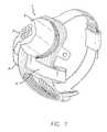
- FIGS. 1 and 2show a retinal stimulation system
- FIG. 3shows components of a fitting system.
- FIG. 4is a diagram of a standard electrode mapping as known in the prior art.
- FIG. 5is a diagram of an electrode mapping in accordance with a first embodiment of the present disclosure.
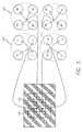
- FIG. 6is a diagram of an electrode mapping in accordance with a second embodiment of the present disclosure.
- FIG. 1 and FIG. 2show a Retinal Stimulation System ( 1 ) wherein a patient/subject is implanted with a visual prosthesis.
- the Retinal Stimulation System ( 1 )is an implantable electronic device containing electrode array ( 2 ) that is electrically coupled by a cable ( 3 ) that pierces sclera of the subject's eye and is electrically coupled to an electronics package ( 4 ), external to the sclera.
- the Retinal Stimulation System ( 1 )is designed to elicit visual percepts in blind subjects with retinitis pigmentosa.
- a Fitting Systemmay be used to configure and optimize the visual prosthesis ( 3 ) of the Retinal Stimulation System ( 1 ).
- the Fitting Systemmay comprise custom software with a graphical user interface (GUI) running on a dedicated laptop computer ( 10 ).
- GUIgraphical user interface
- modules for performing diagnostic checks of the implantloading and executing video configuration files, viewing electrode voltage waveforms, and aiding in conducting psychophysical experiments.
- a video modulecan be used to download a video configuration file to a Video Processing Unit (VPU) ( 20 ) and store it in non-volatile memory to control various aspects of video configuration, e.g. the spatial relationship between the video input and the electrodes, which is one of the main aspects of the present disclosure.
- VPUVideo Processing Unit
- the softwarecan also load a previously used video configuration file from the VPU ( 20 ) for adjustment.
- the Fitting Systemcan be connected to the Psychophysical Test System (PTS), located for example on a dedicated laptop ( 30 ), in order to run psychophysical experiments.
- PTSPsychographic Test System
- the Fitting Systemenables individual electrode control, permitting clinicians to construct test stimuli with control over current amplitude, pulse-width, and frequency of the stimulation.
- the psychophysics moduleallows the clinician to record subject responses.
- the PTSmay include a collection of standard psychophysics experiments developed using for example MATLAB (MathWorks) software and other tools to allow the clinicians to develop customized psychophysics experiment scripts.
- perceptual thresholdUsing the psychophysics module, important perceptual parameters such as perceptual threshold, maximum comfort level, and spatial location of percepts may be reliably measured.
- the fitting softwareenables custom configuration of the transformation between video image and spatio-temporal electrode stimulation parameters in an effort to optimize the effectiveness of the retinal prosthesis for each subject.
- the Fitting System laptop ( 10 )is connected to the VPU ( 20 ) using an optically isolated serial connection adapter ( 40 ). Because it is optically isolated, the serial connection adapter ( 40 ) assures that no electric leakage current can flow from the Fitting System laptop ( 10 ).
- a Video Processing Unit (VPU)20 ) for the subject being tested, a Charged Battery ( 25 ) for VPU ( 20 ), Glasses ( 5 ), a Fitting System (FS) Laptop ( 10 ), a Psychophysical Test System (PTS) Laptop ( 30 ), a PTS CD (not shown), a Communication Adapter (CA) ( 40 ), a USB Drive (Security) (not shown), a USB Drive (Transfer) (not shown), a USB Drive (Video Settings) (not shown), a Patient Input Device (RF Tablet) ( 50 ), a further Patient Input Device (Jog Dial) ( 55 ), Glasses Cable ( 15 ), CA-VPU Cable ( 70 ), CFS-CA Cable ( 45 ), CFS-PTS Cable ( 46 ), Four ( 4 ) Port USB Hub ( 47 ), Mouse ( 60 ), LED Test Array ( 80 ), Archival USB Drive ( 49 ),
- the external components of a Fitting Systemmay be configured as follows.
- the battery ( 25 )is connected with the VPU ( 20 ).
- the PTS Laptop ( 30 )is connected to FS Laptop ( 10 ) using the CFS-PTS Cable ( 46 ).
- the PTS Laptop ( 30 ) and FS Laptop ( 10 )are plugged into the Isolation Transformer (not shown) using the Adapter Cables (not shown).
- the Isolation Transformeris plugged into the wall outlet.
- the four ( 4 ) Port USB Hub ( 47 )is connected to the FS laptop ( 10 ) at the USB port.
- the mouse ( 60 ) and the two Patient Input Devices ( 50 ) and ( 55 )are connected to four ( 4 ) Port USB Hubs ( 47 ).
- the FS laptop ( 10 )is connected to the Communication Adapter (CA) ( 40 ) using the CFS-CA Cable ( 45 ).
- the CA ( 40 )is connected to the VPU ( 20 ) using the CA-VPU Cable ( 70 ).
- the Glasses ( 5 )are connected to the VPU ( 20 ) using the Glasses Cable ( 15 ).
- every electrode in the implanted array of electrodesproduces a spot of light (phosphene) in the visual field.
- a transformationneeds to be specified to map the stimulation of individual electrodes in the stimulating array to specific locations, or regions, in the acquired video image. This transformation is specified in a look-up table referred to as the spatial map.
- spatial mappingis the relationship of a pixel, or pixels, in the camera's view to an electrode on the retina. Due to the optics of the eye, the retina is laid out reverse of the real world and proportional. The scale depends on the distance of the object.
- FIG. 4shows a 4 ⁇ 4 prior art electrode array embodiment, where pixel ( 80 ) is mapped to electrode L 6 , pixel ( 90 ) is mapped to electrode L 7 , pixel ( 100 ) is mapped to electrode M 4 , pixel ( 110 ) is mapped to electrode M 1 , and so on, so that each pixel corresponds to a single electrode and vice versa.
- the corresponding locations of the input video image (pixels)are mapped to the corresponding single electrode in the array.
- a regular spacing of stimulating electrodesmay result in a distorted spatial pattern of phosphenes. Because the ganglion cell axons are stretched away from their foveal cones, a regular pattern of stimulating electrodes may result in a pattern of phosphenes that is compressed to the center of the visual field.
- a group of electrodesare associated with a correspondingly large area in the video image. This is useful for cases in which areas in the array don't yield a bright percept up to the maximum allowed current. When neighboring electrodes are stimulated simultaneously, due to current summation, the percept is brighter. Grouping electrodes create “virtually” one electrode with a larger area, which enable to increase the maximum allowed current. As shown in FIG. 5 , a plurality of electrodes, e.g.
- each electrode of group ( 120 )is mapped to a first average ( 130 ) of four pixels
- each electrode of group ( 140 )is mapped to a second average ( 150 ) of four pixels, and so on.
- FIG. 6shows a further embodiment of the present disclosure, where random mapping is performed.
- pixel ( 160 )instead of being mapped to electrode L 6 , is being mapped to electrode L 7 ( 170 ).
- pixel ( 180 )instead of being mapped to electrode L 2 , is being mapped to electrode M 8 ( 190 ).
- Random mappingcan be used in order to test whether a specific subject is benefitting from spatial modulation in the array. Flexible spatial mapping can also solve wiring mistakes in the implant that are found after the implantation surgery.
- a third embodimentcan also be provided, which is a combination of the first two embodiments.
- a plurality of electrodesis randomly mapped to an average of a plurality of pixels.
- FIGS. 5 and 6have been shown with reference to a 4 ⁇ 4 electrode arrangement for the sake of simplicity.
- Current electrode arrangementsare in a 6 ⁇ 10 array (e.g., electrodes A 1 through F 10 ), and the 6 ⁇ 10 electrode array represents the best mode of the present disclosure.
- the person skilled in the artwill note that the embodiments of FIGS. 5 and 6 can be easily adapted to a 6 ⁇ 10 electrode array environment.
- an improved method of operating a visual prosthesisuses spatial maps to control neural stimulation for correcting distortions from the foveal pit, correcting wiring mistakes in the implant, bypassing broken electrodes, testing the resolution limit, testing the benefit the patient receives from correct spatial mapping, and solving orientation problems.
Landscapes
- Health & Medical Sciences (AREA)
- Engineering & Computer Science (AREA)
- Nuclear Medicine, Radiotherapy & Molecular Imaging (AREA)
- General Health & Medical Sciences (AREA)
- Radiology & Medical Imaging (AREA)
- Biomedical Technology (AREA)
- Life Sciences & Earth Sciences (AREA)
- Animal Behavior & Ethology (AREA)
- Public Health (AREA)
- Veterinary Medicine (AREA)
- General Physics & Mathematics (AREA)
- Theoretical Computer Science (AREA)
- Physics & Mathematics (AREA)
- Ophthalmology & Optometry (AREA)
- Neurosurgery (AREA)
- Neurology (AREA)
- Medical Informatics (AREA)
- Computer Vision & Pattern Recognition (AREA)
- Human Computer Interaction (AREA)
- Quality & Reliability (AREA)
- Software Systems (AREA)
- Multimedia (AREA)
- Cardiology (AREA)
- Heart & Thoracic Surgery (AREA)
- Prostheses (AREA)
- Electrotherapy Devices (AREA)
- Image Processing (AREA)
Abstract
Description
Claims (16)
Priority Applications (3)
| Application Number | Priority Date | Filing Date | Title |
|---|---|---|---|
| US12/114,657US7957811B2 (en) | 2007-05-08 | 2008-05-02 | Spatial mapping for a visual prosthesis |
| US13/094,210US9072900B2 (en) | 2007-05-08 | 2011-04-26 | Spatial mapping for a visual prosthesis |
| US14/792,497US9526894B2 (en) | 2007-05-08 | 2015-07-06 | Spatial mapping for a visual prosthesis |
Applications Claiming Priority (3)
| Application Number | Priority Date | Filing Date | Title |
|---|---|---|---|
| US92840707P | 2007-05-08 | 2007-05-08 | |
| US92844007P | 2007-05-08 | 2007-05-08 | |
| US12/114,657US7957811B2 (en) | 2007-05-08 | 2008-05-02 | Spatial mapping for a visual prosthesis |
Related Child Applications (1)
| Application Number | Title | Priority Date | Filing Date |
|---|---|---|---|
| US13/094,210DivisionUS9072900B2 (en) | 2007-05-08 | 2011-04-26 | Spatial mapping for a visual prosthesis |
Publications (2)
| Publication Number | Publication Date |
|---|---|
| US20080281377A1 US20080281377A1 (en) | 2008-11-13 |
| US7957811B2true US7957811B2 (en) | 2011-06-07 |
Family
ID=39584407
Family Applications (8)
| Application Number | Title | Priority Date | Filing Date |
|---|---|---|---|
| US12/114,657Active2030-01-02US7957811B2 (en) | 2007-05-08 | 2008-05-02 | Spatial mapping for a visual prosthesis |
| US12/114,635Active2031-03-10US8195301B2 (en) | 2006-04-28 | 2008-05-02 | Video configuration file editor for visual prosthesis fitting and related method |
| US12/114,557Active2031-06-08US8239035B2 (en) | 2007-05-08 | 2008-05-02 | Method and system for providing stimulation inputs to a visual prosthesis implant |
| US13/094,210Active2031-01-26US9072900B2 (en) | 2007-05-08 | 2011-04-26 | Spatial mapping for a visual prosthesis |
| US13/462,646ActiveUS8694111B2 (en) | 2006-04-28 | 2012-05-02 | Video configuration file editor for visual prosthesis fitting |
| US13/538,987ActiveUS8620443B2 (en) | 2007-05-08 | 2012-06-29 | Method and system for providing stimulation inputs to a visual prosthesis implant |
| US14/101,178ActiveUS9180296B2 (en) | 2007-05-08 | 2013-12-09 | Method and system for providing stimulation inputs to a visual prosthesis implant |
| US14/792,497Expired - Fee RelatedUS9526894B2 (en) | 2007-05-08 | 2015-07-06 | Spatial mapping for a visual prosthesis |
Family Applications After (7)
| Application Number | Title | Priority Date | Filing Date |
|---|---|---|---|
| US12/114,635Active2031-03-10US8195301B2 (en) | 2006-04-28 | 2008-05-02 | Video configuration file editor for visual prosthesis fitting and related method |
| US12/114,557Active2031-06-08US8239035B2 (en) | 2007-05-08 | 2008-05-02 | Method and system for providing stimulation inputs to a visual prosthesis implant |
| US13/094,210Active2031-01-26US9072900B2 (en) | 2007-05-08 | 2011-04-26 | Spatial mapping for a visual prosthesis |
| US13/462,646ActiveUS8694111B2 (en) | 2006-04-28 | 2012-05-02 | Video configuration file editor for visual prosthesis fitting |
| US13/538,987ActiveUS8620443B2 (en) | 2007-05-08 | 2012-06-29 | Method and system for providing stimulation inputs to a visual prosthesis implant |
| US14/101,178ActiveUS9180296B2 (en) | 2007-05-08 | 2013-12-09 | Method and system for providing stimulation inputs to a visual prosthesis implant |
| US14/792,497Expired - Fee RelatedUS9526894B2 (en) | 2007-05-08 | 2015-07-06 | Spatial mapping for a visual prosthesis |
Country Status (4)
| Country | Link |
|---|---|
| US (8) | US7957811B2 (en) |
| EP (2) | EP2164563B1 (en) |
| AU (2) | AU2008251630B2 (en) |
| WO (3) | WO2008140981A1 (en) |
Cited By (11)
| Publication number | Priority date | Publication date | Assignee | Title |
|---|---|---|---|---|
| US20080294225A1 (en)* | 2007-05-08 | 2008-11-27 | Arup Roy | Video configuration file editor for visual prosthesis fitting and related method |
| US8428740B2 (en) | 2010-08-06 | 2013-04-23 | Nano-Retina, Inc. | Retinal prosthesis techniques |
| US8442641B2 (en) | 2010-08-06 | 2013-05-14 | Nano-Retina, Inc. | Retinal prosthesis techniques |
| US8571669B2 (en) | 2011-02-24 | 2013-10-29 | Nano-Retina, Inc. | Retinal prosthesis with efficient processing circuits |
| US8706243B2 (en) | 2009-02-09 | 2014-04-22 | Rainbow Medical Ltd. | Retinal prosthesis techniques |
| US8718784B2 (en) | 2010-01-14 | 2014-05-06 | Nano-Retina, Inc. | Penetrating electrodes for retinal stimulation |
| US20160045734A1 (en)* | 2014-08-12 | 2016-02-18 | Second Sight Medical Products, Inc. | Pattern Detection and Location Indication for a Visual Prosthesis |
| US9265945B2 (en) | 2009-02-09 | 2016-02-23 | Nano-Retina, Inc. | Retinal prosthesis |
| US9331791B2 (en) | 2014-01-21 | 2016-05-03 | Nano Retina Ltd. | Transfer of power and data |
| US9370417B2 (en) | 2013-03-14 | 2016-06-21 | Nano-Retina, Inc. | Foveated retinal prosthesis |
| US9474902B2 (en) | 2013-12-31 | 2016-10-25 | Nano Retina Ltd. | Wearable apparatus for delivery of power to a retinal prosthesis |
Families Citing this family (19)
| Publication number | Priority date | Publication date | Assignee | Title |
|---|---|---|---|---|
| US7877866B1 (en)* | 2005-10-26 | 2011-02-01 | Second Sight Medical Products, Inc. | Flexible circuit electrode array and method of manufacturing the same |
| EP2364179B1 (en) | 2008-09-18 | 2015-12-23 | Second Sight Medical Products | Techniques and functional electrical stimulation to eliminate discomfort during electrical stimulation of the retina |
| EP2401028A1 (en)* | 2009-02-27 | 2012-01-04 | IMI Intelligent Medical Implants AG | Visual prosthesis and retina stimulation device for same |
| WO2011072322A1 (en)* | 2009-12-18 | 2011-06-23 | The Bionic Ear Institute | Method and apparatus for stimulating retinal nerve cells |
| US20110154261A1 (en)* | 2009-12-21 | 2011-06-23 | Starkey Laboratories, Inc. | User interface with ribbon usage for hearing aid fitting systems |
| US9089702B2 (en) | 2011-10-03 | 2015-07-28 | Second Sight Medical Products, Inc. | Hybrid fitting for a visual prosthesis |
| US8954456B1 (en) | 2013-03-29 | 2015-02-10 | Measured Progress, Inc. | Translation and transcription content conversion |
| US10426598B2 (en)* | 2014-03-25 | 2019-10-01 | Monash University | Image processing method and system for irregular output patterns |
| US11461936B2 (en) | 2015-03-17 | 2022-10-04 | Raytrx, Llc | Wearable image manipulation and control system with micro-displays and augmentation of vision and sensing in augmented reality glasses |
| US11956414B2 (en) | 2015-03-17 | 2024-04-09 | Raytrx, Llc | Wearable image manipulation and control system with correction for vision defects and augmentation of vision and sensing |
| US11016302B2 (en) | 2015-03-17 | 2021-05-25 | Raytrx, Llc | Wearable image manipulation and control system with high resolution micro-displays and dynamic opacity augmentation in augmented reality glasses |
| WO2016149536A1 (en) | 2015-03-17 | 2016-09-22 | Ocutrx Vision Technologies, Llc. | Correction of vision defects using a visual display |
| US9808625B2 (en) | 2015-05-01 | 2017-11-07 | Second Sight Medical Products, Inc. | Spatial fitting by percept location tracking |
| CN106137532B (en)* | 2016-09-19 | 2019-01-25 | 清华大学 | an image processing method |
| CN110913810B (en)* | 2017-07-18 | 2022-06-17 | 极视科技(海南)有限公司 | A kind of artificial artificial eye image acquisition and processing method |
| WO2019014848A1 (en)* | 2017-07-18 | 2019-01-24 | 辛特科技有限公司 | System for use in image acquisition and processing by artificial eye |
| CN107749053A (en)* | 2017-10-24 | 2018-03-02 | 郑州布恩科技有限公司 | A kind of binocular image collection and pretreatment unit and method for vision prosthesis |
| WO2021168449A1 (en) | 2020-02-21 | 2021-08-26 | Raytrx, Llc | All-digital multi-option 3d surgery visualization system and control |
| US12142367B2 (en) | 2020-02-21 | 2024-11-12 | Raytrx, Llc | Surgery visualization theatre |
Citations (9)
| Publication number | Priority date | Publication date | Assignee | Title |
|---|---|---|---|---|
| US5109844A (en) | 1990-10-11 | 1992-05-05 | Duke University | Retinal microstimulation |
| US5740285A (en) | 1989-12-08 | 1998-04-14 | Xerox Corporation | Image reduction/enlargement technique |
| US5935155A (en) | 1998-03-13 | 1999-08-10 | John Hopkins University, School Of Medicine | Visual prosthesis and method of using same |
| WO2001091852A1 (en) | 2000-05-26 | 2001-12-06 | Second Sight, Llc | Video processing methods for improving visual acuity and/or perceived image resolution |
| US6400989B1 (en) | 1997-02-21 | 2002-06-04 | Intelligent Implants Gmbh | Adaptive sensory-motor encoder for visual or acoustic prosthesis |
| US6458157B1 (en) | 1997-08-04 | 2002-10-01 | Suaning Gregg Joergen | Retinal stimulator |
| WO2002089912A2 (en) | 2001-05-03 | 2002-11-14 | Universite Catholique De Louvain | Vision rehabilitation method and device |
| WO2007127444A2 (en) | 2006-04-28 | 2007-11-08 | Second Sight Medical Products, Inc. | Visual prosthesis fitting |
| US7321796B2 (en)* | 2003-05-01 | 2008-01-22 | California Institute Of Technology | Method and system for training a visual prosthesis |
Family Cites Families (14)
| Publication number | Priority date | Publication date | Assignee | Title |
|---|---|---|---|---|
| US4573481A (en) | 1984-06-25 | 1986-03-04 | Huntington Institute Of Applied Research | Implantable electrode array |
| US4628933A (en) | 1985-07-23 | 1986-12-16 | Michelson Robin P | Method and apparatus for visual prosthesis |
| US4837049A (en) | 1986-06-17 | 1989-06-06 | Alfred E. Mann Foundation For Scientific Research | Method of making an electrode array |
| US5215088A (en) | 1989-11-07 | 1993-06-01 | The University Of Utah | Three-dimensional electrode device |
| US8180453B2 (en)* | 1999-03-24 | 2012-05-15 | Second Sight Medical Products, Inc. | Electrode array for neural stimulation |
| US6836514B2 (en)* | 2001-07-10 | 2004-12-28 | Motorola, Inc. | Method for the detection and recovery of errors in the frame overhead of digital video decoding systems |
| US7565202B2 (en)* | 2002-07-30 | 2009-07-21 | Second Sight Medical Products, Inc. | Field focusing and mapping in an electrode array |
| US7963652B2 (en)* | 2003-11-14 | 2011-06-21 | Queen's University At Kingston | Method and apparatus for calibration-free eye tracking |
| US20050182456A1 (en)* | 2004-02-18 | 2005-08-18 | Ziobro John F. | Automated cortical mapping |
| US7738962B2 (en)* | 2005-02-16 | 2010-06-15 | Second Sight Medical Products, Inc. | Fitting of brightness in a visual prosthesis |
| US20060178711A1 (en)* | 2005-02-07 | 2006-08-10 | Cochlear Limited | Prosthetic hearing implant fitting technique |
| EP1937358B1 (en) | 2005-09-16 | 2016-11-02 | Second Sight Medical Products, Inc. | Downloadable filters for a visual prosthesis |
| EP1951366B1 (en)* | 2005-09-16 | 2013-04-17 | Second Sight Medical Products, Inc. | Neural stimulation for increased contrast |
| WO2008140981A1 (en)* | 2007-05-08 | 2008-11-20 | Second Sight Medical Products, Inc. | Spatial mapping for a visual prosthesis |
- 2008
- 2008-05-02WOPCT/US2008/062540patent/WO2008140981A1/enactiveApplication Filing
- 2008-05-02USUS12/114,657patent/US7957811B2/enactiveActive
- 2008-05-02WOPCT/US2008/062510patent/WO2008140976A1/enactiveApplication Filing
- 2008-05-02EPEP08769281.0Apatent/EP2164563B1/ennot_activeNot-in-force
- 2008-05-02WOPCT/US2008/062533patent/WO2008140980A1/enactiveApplication Filing
- 2008-05-02USUS12/114,635patent/US8195301B2/enactiveActive
- 2008-05-02AUAU2008251630Apatent/AU2008251630B2/ennot_activeCeased
- 2008-05-02AUAU2008251634Apatent/AU2008251634B2/ennot_activeCeased
- 2008-05-02EPEP08755030.7Apatent/EP2155327B1/ennot_activeNot-in-force
- 2008-05-02USUS12/114,557patent/US8239035B2/enactiveActive
- 2011
- 2011-04-26USUS13/094,210patent/US9072900B2/enactiveActive
- 2012
- 2012-05-02USUS13/462,646patent/US8694111B2/enactiveActive
- 2012-06-29USUS13/538,987patent/US8620443B2/enactiveActive
- 2013
- 2013-12-09USUS14/101,178patent/US9180296B2/enactiveActive
- 2015
- 2015-07-06USUS14/792,497patent/US9526894B2/ennot_activeExpired - Fee Related
Patent Citations (9)
| Publication number | Priority date | Publication date | Assignee | Title |
|---|---|---|---|---|
| US5740285A (en) | 1989-12-08 | 1998-04-14 | Xerox Corporation | Image reduction/enlargement technique |
| US5109844A (en) | 1990-10-11 | 1992-05-05 | Duke University | Retinal microstimulation |
| US6400989B1 (en) | 1997-02-21 | 2002-06-04 | Intelligent Implants Gmbh | Adaptive sensory-motor encoder for visual or acoustic prosthesis |
| US6458157B1 (en) | 1997-08-04 | 2002-10-01 | Suaning Gregg Joergen | Retinal stimulator |
| US5935155A (en) | 1998-03-13 | 1999-08-10 | John Hopkins University, School Of Medicine | Visual prosthesis and method of using same |
| WO2001091852A1 (en) | 2000-05-26 | 2001-12-06 | Second Sight, Llc | Video processing methods for improving visual acuity and/or perceived image resolution |
| WO2002089912A2 (en) | 2001-05-03 | 2002-11-14 | Universite Catholique De Louvain | Vision rehabilitation method and device |
| US7321796B2 (en)* | 2003-05-01 | 2008-01-22 | California Institute Of Technology | Method and system for training a visual prosthesis |
| WO2007127444A2 (en) | 2006-04-28 | 2007-11-08 | Second Sight Medical Products, Inc. | Visual prosthesis fitting |
Cited By (23)
| Publication number | Priority date | Publication date | Assignee | Title |
|---|---|---|---|---|
| US9072900B2 (en)* | 2007-05-08 | 2015-07-07 | Second Sight Medical Products, Inc. | Spatial mapping for a visual prosthesis |
| US20110202110A1 (en)* | 2007-05-08 | 2011-08-18 | Avraham Caspi | Spatial Mapping for a Visual Prosthesis |
| US8195301B2 (en)* | 2007-05-08 | 2012-06-05 | Second Sight Medical Products, Inc. | Video configuration file editor for visual prosthesis fitting and related method |
| US20120221077A1 (en)* | 2007-05-08 | 2012-08-30 | Arup Roy | Video Configuration File Editor for Visual Prosthesis Fitting |
| US9526894B2 (en)* | 2007-05-08 | 2016-12-27 | Second Sight Medical Products, Inc. | Spatial mapping for a visual prosthesis |
| US20080294225A1 (en)* | 2007-05-08 | 2008-11-27 | Arup Roy | Video configuration file editor for visual prosthesis fitting and related method |
| US20150306389A1 (en)* | 2007-05-08 | 2015-10-29 | Second Sight Medical Products, Inc. | Spatial mapping for a visual prosthesis |
| US8694111B2 (en)* | 2007-05-08 | 2014-04-08 | Second Sight Medical Products, Inc. | Video configuration file editor for visual prosthesis fitting |
| US9265945B2 (en) | 2009-02-09 | 2016-02-23 | Nano-Retina, Inc. | Retinal prosthesis |
| US8706243B2 (en) | 2009-02-09 | 2014-04-22 | Rainbow Medical Ltd. | Retinal prosthesis techniques |
| US9907969B2 (en) | 2009-02-09 | 2018-03-06 | Nano-Retina, Inc. | Retinal prosthesis with an external power source |
| US9198753B2 (en) | 2009-02-09 | 2015-12-01 | Nano-Retina Inc. | Techniques for powering a retinal prosthesis |
| US9566191B2 (en) | 2009-02-09 | 2017-02-14 | Nano-Retina, Inc. | Retinal prosthesis with visible-light filter |
| US8718784B2 (en) | 2010-01-14 | 2014-05-06 | Nano-Retina, Inc. | Penetrating electrodes for retinal stimulation |
| US8428740B2 (en) | 2010-08-06 | 2013-04-23 | Nano-Retina, Inc. | Retinal prosthesis techniques |
| US8442641B2 (en) | 2010-08-06 | 2013-05-14 | Nano-Retina, Inc. | Retinal prosthesis techniques |
| US9192464B2 (en) | 2011-02-24 | 2015-11-24 | Nano-Retina, Inc. | Retinal prosthesis with efficient processing circuits |
| US8571669B2 (en) | 2011-02-24 | 2013-10-29 | Nano-Retina, Inc. | Retinal prosthesis with efficient processing circuits |
| US9370417B2 (en) | 2013-03-14 | 2016-06-21 | Nano-Retina, Inc. | Foveated retinal prosthesis |
| US9474902B2 (en) | 2013-12-31 | 2016-10-25 | Nano Retina Ltd. | Wearable apparatus for delivery of power to a retinal prosthesis |
| US9331791B2 (en) | 2014-01-21 | 2016-05-03 | Nano Retina Ltd. | Transfer of power and data |
| US9526896B2 (en)* | 2014-08-12 | 2016-12-27 | Second Sight Medical Products, Inc. | Pattern detection and location indication for a visual prosthesis |
| US20160045734A1 (en)* | 2014-08-12 | 2016-02-18 | Second Sight Medical Products, Inc. | Pattern Detection and Location Indication for a Visual Prosthesis |
Also Published As
| Publication number | Publication date |
|---|---|
| US9072900B2 (en) | 2015-07-07 |
| US8195301B2 (en) | 2012-06-05 |
| EP2164563A1 (en) | 2010-03-24 |
| US20120221077A1 (en) | 2012-08-30 |
| US8239035B2 (en) | 2012-08-07 |
| EP2155327A1 (en) | 2010-02-24 |
| US20120277827A1 (en) | 2012-11-01 |
| AU2008251634B2 (en) | 2013-03-14 |
| WO2008140980A1 (en) | 2008-11-20 |
| AU2008251634A1 (en) | 2008-11-20 |
| US8694111B2 (en) | 2014-04-08 |
| US20140100629A1 (en) | 2014-04-10 |
| US9526894B2 (en) | 2016-12-27 |
| US20150306389A1 (en) | 2015-10-29 |
| AU2008251630B2 (en) | 2013-05-23 |
| US9180296B2 (en) | 2015-11-10 |
| US8620443B2 (en) | 2013-12-31 |
| WO2008140976A1 (en) | 2008-11-20 |
| WO2008140981A1 (en) | 2008-11-20 |
| AU2008251630A1 (en) | 2008-11-20 |
| US20110202110A1 (en) | 2011-08-18 |
| US20090210031A1 (en) | 2009-08-20 |
| US20080294225A1 (en) | 2008-11-27 |
| EP2164563B1 (en) | 2017-10-25 |
| EP2155327B1 (en) | 2014-07-23 |
| US20080281377A1 (en) | 2008-11-13 |
Similar Documents
| Publication | Publication Date | Title |
|---|---|---|
| US7957811B2 (en) | Spatial mapping for a visual prosthesis | |
| US8620442B2 (en) | Multi-electrode integration in a visual prosthesis | |
| EP2091607B1 (en) | Visual prosthesis | |
| US10052481B2 (en) | Visual prosthesis | |
| Humayun et al. | The bionic eye: a quarter century of retinal prosthesis research and development | |
| US9108056B2 (en) | Video processing unit for a visual prosthetic apparatus | |
| US9072888B2 (en) | Visual prosthesis with an improved electrode array adapted for foveal stimulation | |
| US9744359B2 (en) | Apparatus and method for visual stimulation indication | |
| Lowery | Introducing the monash vision group's cortical prosthesis | |
| US20090118793A1 (en) | Video Processing Unit for a Visual Prosthetic Apparatus | |
| US9205257B1 (en) | Method and apparatus for inducing the perception of color in a visual prosthesis | |
| Li | A fast and flexible computer vision system for implanted visual prostheses | |
| US9943688B2 (en) | Wireless visual prosthesis with remote driver and coil | |
| Weiland | Vision Prosthesis |
Legal Events
| Date | Code | Title | Description |
|---|---|---|---|
| AS | Assignment | Owner name:SECOND SIGHT MEDICAL PRODUCTS, INC., CALIFORNIA Free format text:ASSIGNMENT OF ASSIGNORS INTEREST;ASSIGNORS:MCMAHON, MATTHEW J., PH.D.;GREENBERG, ROBERT J., M.D., PH.D.;CASPI, AVRAHAM, PH.D.;AND OTHERS;REEL/FRAME:021083/0336;SIGNING DATES FROM 20080514 TO 20080603 Owner name:SECOND SIGHT MEDICAL PRODUCTS, INC., CALIFORNIA Free format text:ASSIGNMENT OF ASSIGNORS INTEREST;ASSIGNORS:MCMAHON, MATTHEW J., PH.D.;GREENBERG, ROBERT J., M.D., PH.D.;CASPI, AVRAHAM, PH.D.;AND OTHERS;SIGNING DATES FROM 20080514 TO 20080603;REEL/FRAME:021083/0336 | |
| STCF | Information on status: patent grant | Free format text:PATENTED CASE | |
| FPAY | Fee payment | Year of fee payment:4 | |
| MAFP | Maintenance fee payment | Free format text:PAYMENT OF MAINTENANCE FEE, 8TH YR, SMALL ENTITY (ORIGINAL EVENT CODE: M2552) Year of fee payment:8 | |
| MAFP | Maintenance fee payment | Free format text:PAYMENT OF MAINTENANCE FEE, 12TH YR, SMALL ENTITY (ORIGINAL EVENT CODE: M2553); ENTITY STATUS OF PATENT OWNER: SMALL ENTITY Year of fee payment:12 | |
| AS | Assignment | Owner name:VIVANI MEDICAL, INC, CALIFORNIA Free format text:MERGER AND CHANGE OF NAME;ASSIGNORS:SECOND SIGHT MEDICAL PRODUCTS, INC;VIVANI MEDICAL, INC;REEL/FRAME:062230/0418 Effective date:20220825 | |
| AS | Assignment | Owner name:CORTIGENT, INC., CALIFORNIA Free format text:ASSIGNMENT OF ASSIGNORS INTEREST;ASSIGNOR:VIVANI MEDICAL, INC.;REEL/FRAME:062590/0103 Effective date:20221228 |