US7957733B2 - Method and apparatus for multimedia communications with different user terminals - Google Patents
Method and apparatus for multimedia communications with different user terminalsDownload PDFInfo
- Publication number
- US7957733B2 US7957733B2US11/802,418US80241807AUS7957733B2US 7957733 B2US7957733 B2US 7957733B2US 80241807 AUS80241807 AUS 80241807AUS 7957733 B2US7957733 B2US 7957733B2
- Authority
- US
- United States
- Prior art keywords
- multimedia content
- content item
- destination device
- source
- signal format
- Prior art date
- Legal status (The legal status is an assumption and is not a legal conclusion. Google has not performed a legal analysis and makes no representation as to the accuracy of the status listed.)
- Expired - Fee Related, expires
Links
Images


Classifications
- G—PHYSICS
- G06—COMPUTING OR CALCULATING; COUNTING
- G06Q—INFORMATION AND COMMUNICATION TECHNOLOGY [ICT] SPECIALLY ADAPTED FOR ADMINISTRATIVE, COMMERCIAL, FINANCIAL, MANAGERIAL OR SUPERVISORY PURPOSES; SYSTEMS OR METHODS SPECIALLY ADAPTED FOR ADMINISTRATIVE, COMMERCIAL, FINANCIAL, MANAGERIAL OR SUPERVISORY PURPOSES, NOT OTHERWISE PROVIDED FOR
- G06Q10/00—Administration; Management
- G06Q10/08—Logistics, e.g. warehousing, loading or distribution; Inventory or stock management
- G06Q10/087—Inventory or stock management, e.g. order filling, procurement or balancing against orders
- G—PHYSICS
- G06—COMPUTING OR CALCULATING; COUNTING
- G06Q—INFORMATION AND COMMUNICATION TECHNOLOGY [ICT] SPECIALLY ADAPTED FOR ADMINISTRATIVE, COMMERCIAL, FINANCIAL, MANAGERIAL OR SUPERVISORY PURPOSES; SYSTEMS OR METHODS SPECIALLY ADAPTED FOR ADMINISTRATIVE, COMMERCIAL, FINANCIAL, MANAGERIAL OR SUPERVISORY PURPOSES, NOT OTHERWISE PROVIDED FOR
- G06Q30/00—Commerce
- G06Q30/02—Marketing; Price estimation or determination; Fundraising
- G—PHYSICS
- G06—COMPUTING OR CALCULATING; COUNTING
- G06Q—INFORMATION AND COMMUNICATION TECHNOLOGY [ICT] SPECIALLY ADAPTED FOR ADMINISTRATIVE, COMMERCIAL, FINANCIAL, MANAGERIAL OR SUPERVISORY PURPOSES; SYSTEMS OR METHODS SPECIALLY ADAPTED FOR ADMINISTRATIVE, COMMERCIAL, FINANCIAL, MANAGERIAL OR SUPERVISORY PURPOSES, NOT OTHERWISE PROVIDED FOR
- G06Q30/00—Commerce
- G06Q30/06—Buying, selling or leasing transactions
- H—ELECTRICITY
- H04—ELECTRIC COMMUNICATION TECHNIQUE
- H04L—TRANSMISSION OF DIGITAL INFORMATION, e.g. TELEGRAPHIC COMMUNICATION
- H04L63/00—Network architectures or network communication protocols for network security
- H04L63/04—Network architectures or network communication protocols for network security for providing a confidential data exchange among entities communicating through data packet networks
- H04L63/0428—Network architectures or network communication protocols for network security for providing a confidential data exchange among entities communicating through data packet networks wherein the data content is protected, e.g. by encrypting or encapsulating the payload
- H04L63/0492—Network architectures or network communication protocols for network security for providing a confidential data exchange among entities communicating through data packet networks wherein the data content is protected, e.g. by encrypting or encapsulating the payload by using a location-limited connection, e.g. near-field communication or limited proximity of entities
- H—ELECTRICITY
- H04—ELECTRIC COMMUNICATION TECHNIQUE
- H04L—TRANSMISSION OF DIGITAL INFORMATION, e.g. TELEGRAPHIC COMMUNICATION
- H04L65/00—Network arrangements, protocols or services for supporting real-time applications in data packet communication
- H04L65/1066—Session management
- H04L65/1083—In-session procedures
- H04L65/1094—Inter-user-equipment sessions transfer or sharing
- H—ELECTRICITY
- H04—ELECTRIC COMMUNICATION TECHNIQUE
- H04L—TRANSMISSION OF DIGITAL INFORMATION, e.g. TELEGRAPHIC COMMUNICATION
- H04L65/00—Network arrangements, protocols or services for supporting real-time applications in data packet communication
- H04L65/60—Network streaming of media packets
- H04L65/61—Network streaming of media packets for supporting one-way streaming services, e.g. Internet radio
- H04L65/612—Network streaming of media packets for supporting one-way streaming services, e.g. Internet radio for unicast
- H—ELECTRICITY
- H04—ELECTRIC COMMUNICATION TECHNIQUE
- H04L—TRANSMISSION OF DIGITAL INFORMATION, e.g. TELEGRAPHIC COMMUNICATION
- H04L65/00—Network arrangements, protocols or services for supporting real-time applications in data packet communication
- H04L65/80—Responding to QoS
- H—ELECTRICITY
- H04—ELECTRIC COMMUNICATION TECHNIQUE
- H04L—TRANSMISSION OF DIGITAL INFORMATION, e.g. TELEGRAPHIC COMMUNICATION
- H04L67/00—Network arrangements or protocols for supporting network services or applications
- H04L67/01—Protocols
- H04L67/04—Protocols specially adapted for terminals or networks with limited capabilities; specially adapted for terminal portability
- H—ELECTRICITY
- H04—ELECTRIC COMMUNICATION TECHNIQUE
- H04L—TRANSMISSION OF DIGITAL INFORMATION, e.g. TELEGRAPHIC COMMUNICATION
- H04L67/00—Network arrangements or protocols for supporting network services or applications
- H04L67/50—Network services
- H04L67/52—Network services specially adapted for the location of the user terminal
- H—ELECTRICITY
- H04—ELECTRIC COMMUNICATION TECHNIQUE
- H04L—TRANSMISSION OF DIGITAL INFORMATION, e.g. TELEGRAPHIC COMMUNICATION
- H04L67/00—Network arrangements or protocols for supporting network services or applications
- H04L67/50—Network services
- H04L67/56—Provisioning of proxy services
- H04L67/564—Enhancement of application control based on intercepted application data
- H—ELECTRICITY
- H04—ELECTRIC COMMUNICATION TECHNIQUE
- H04L—TRANSMISSION OF DIGITAL INFORMATION, e.g. TELEGRAPHIC COMMUNICATION
- H04L67/00—Network arrangements or protocols for supporting network services or applications
- H04L67/50—Network services
- H04L67/56—Provisioning of proxy services
- H04L67/568—Storing data temporarily at an intermediate stage, e.g. caching
- H—ELECTRICITY
- H04—ELECTRIC COMMUNICATION TECHNIQUE
- H04L—TRANSMISSION OF DIGITAL INFORMATION, e.g. TELEGRAPHIC COMMUNICATION
- H04L67/00—Network arrangements or protocols for supporting network services or applications
- H04L67/50—Network services
- H04L67/60—Scheduling or organising the servicing of application requests, e.g. requests for application data transmissions using the analysis and optimisation of the required network resources
- H04L67/61—Scheduling or organising the servicing of application requests, e.g. requests for application data transmissions using the analysis and optimisation of the required network resources taking into account QoS or priority requirements
- H—ELECTRICITY
- H04—ELECTRIC COMMUNICATION TECHNIQUE
- H04M—TELEPHONIC COMMUNICATION
- H04M1/00—Substation equipment, e.g. for use by subscribers
- H04M1/72—Mobile telephones; Cordless telephones, i.e. devices for establishing wireless links to base stations without route selection
- H04M1/724—User interfaces specially adapted for cordless or mobile telephones
- H04M1/72403—User interfaces specially adapted for cordless or mobile telephones with means for local support of applications that increase the functionality
- H04M1/72409—User interfaces specially adapted for cordless or mobile telephones with means for local support of applications that increase the functionality by interfacing with external accessories
- H04M1/72412—User interfaces specially adapted for cordless or mobile telephones with means for local support of applications that increase the functionality by interfacing with external accessories using two-way short-range wireless interfaces
- H—ELECTRICITY
- H04—ELECTRIC COMMUNICATION TECHNIQUE
- H04N—PICTORIAL COMMUNICATION, e.g. TELEVISION
- H04N21/00—Selective content distribution, e.g. interactive television or video on demand [VOD]
- H04N21/20—Servers specifically adapted for the distribution of content, e.g. VOD servers; Operations thereof
- H04N21/21—Server components or server architectures
- H04N21/222—Secondary servers, e.g. proxy server, cable television Head-end
- H—ELECTRICITY
- H04—ELECTRIC COMMUNICATION TECHNIQUE
- H04N—PICTORIAL COMMUNICATION, e.g. TELEVISION
- H04N21/00—Selective content distribution, e.g. interactive television or video on demand [VOD]
- H04N21/20—Servers specifically adapted for the distribution of content, e.g. VOD servers; Operations thereof
- H04N21/23—Processing of content or additional data; Elementary server operations; Server middleware
- H04N21/234—Processing of video elementary streams, e.g. splicing of video streams or manipulating encoded video stream scene graphs
- H04N21/2343—Processing of video elementary streams, e.g. splicing of video streams or manipulating encoded video stream scene graphs involving reformatting operations of video signals for distribution or compliance with end-user requests or end-user device requirements
- H04N21/234327—Processing of video elementary streams, e.g. splicing of video streams or manipulating encoded video stream scene graphs involving reformatting operations of video signals for distribution or compliance with end-user requests or end-user device requirements by decomposing into layers, e.g. base layer and one or more enhancement layers
- H—ELECTRICITY
- H04—ELECTRIC COMMUNICATION TECHNIQUE
- H04N—PICTORIAL COMMUNICATION, e.g. TELEVISION
- H04N21/00—Selective content distribution, e.g. interactive television or video on demand [VOD]
- H04N21/20—Servers specifically adapted for the distribution of content, e.g. VOD servers; Operations thereof
- H04N21/25—Management operations performed by the server for facilitating the content distribution or administrating data related to end-users or client devices, e.g. end-user or client device authentication, learning user preferences for recommending movies
- H04N21/258—Client or end-user data management, e.g. managing client capabilities, user preferences or demographics, processing of multiple end-users preferences to derive collaborative data
- H04N21/25808—Management of client data
- H04N21/25841—Management of client data involving the geographical location of the client
- H—ELECTRICITY
- H04—ELECTRIC COMMUNICATION TECHNIQUE
- H04N—PICTORIAL COMMUNICATION, e.g. TELEVISION
- H04N21/00—Selective content distribution, e.g. interactive television or video on demand [VOD]
- H04N21/40—Client devices specifically adapted for the reception of or interaction with content, e.g. set-top-box [STB]; Operations thereof
- H04N21/41—Structure of client; Structure of client peripherals
- H04N21/4104—Peripherals receiving signals from specially adapted client devices
- H04N21/4122—Peripherals receiving signals from specially adapted client devices additional display device, e.g. video projector
- H—ELECTRICITY
- H04—ELECTRIC COMMUNICATION TECHNIQUE
- H04N—PICTORIAL COMMUNICATION, e.g. TELEVISION
- H04N21/00—Selective content distribution, e.g. interactive television or video on demand [VOD]
- H04N21/40—Client devices specifically adapted for the reception of or interaction with content, e.g. set-top-box [STB]; Operations thereof
- H04N21/41—Structure of client; Structure of client peripherals
- H04N21/414—Specialised client platforms, e.g. receiver in car or embedded in a mobile appliance
- H04N21/41407—Specialised client platforms, e.g. receiver in car or embedded in a mobile appliance embedded in a portable device, e.g. video client on a mobile phone, PDA, laptop
- H—ELECTRICITY
- H04—ELECTRIC COMMUNICATION TECHNIQUE
- H04N—PICTORIAL COMMUNICATION, e.g. TELEVISION
- H04N21/00—Selective content distribution, e.g. interactive television or video on demand [VOD]
- H04N21/40—Client devices specifically adapted for the reception of or interaction with content, e.g. set-top-box [STB]; Operations thereof
- H04N21/43—Processing of content or additional data, e.g. demultiplexing additional data from a digital video stream; Elementary client operations, e.g. monitoring of home network or synchronising decoder's clock; Client middleware
- H04N21/44—Processing of video elementary streams, e.g. splicing a video clip retrieved from local storage with an incoming video stream or rendering scenes according to encoded video stream scene graphs
- H04N21/4402—Processing of video elementary streams, e.g. splicing a video clip retrieved from local storage with an incoming video stream or rendering scenes according to encoded video stream scene graphs involving reformatting operations of video signals for household redistribution, storage or real-time display
- H—ELECTRICITY
- H04—ELECTRIC COMMUNICATION TECHNIQUE
- H04N—PICTORIAL COMMUNICATION, e.g. TELEVISION
- H04N21/00—Selective content distribution, e.g. interactive television or video on demand [VOD]
- H04N21/40—Client devices specifically adapted for the reception of or interaction with content, e.g. set-top-box [STB]; Operations thereof
- H04N21/47—End-user applications
- H04N21/472—End-user interface for requesting content, additional data or services; End-user interface for interacting with content, e.g. for content reservation or setting reminders, for requesting event notification, for manipulating displayed content
- H04N21/47202—End-user interface for requesting content, additional data or services; End-user interface for interacting with content, e.g. for content reservation or setting reminders, for requesting event notification, for manipulating displayed content for requesting content on demand, e.g. video on demand
- H—ELECTRICITY
- H04—ELECTRIC COMMUNICATION TECHNIQUE
- H04N—PICTORIAL COMMUNICATION, e.g. TELEVISION
- H04N21/00—Selective content distribution, e.g. interactive television or video on demand [VOD]
- H04N21/40—Client devices specifically adapted for the reception of or interaction with content, e.g. set-top-box [STB]; Operations thereof
- H04N21/47—End-user applications
- H04N21/478—Supplemental services, e.g. displaying phone caller identification, shopping application
- H04N21/4784—Supplemental services, e.g. displaying phone caller identification, shopping application receiving rewards
- H—ELECTRICITY
- H04—ELECTRIC COMMUNICATION TECHNIQUE
- H04N—PICTORIAL COMMUNICATION, e.g. TELEVISION
- H04N21/00—Selective content distribution, e.g. interactive television or video on demand [VOD]
- H04N21/80—Generation or processing of content or additional data by content creator independently of the distribution process; Content per se
- H04N21/81—Monomedia components thereof
- H04N21/812—Monomedia components thereof involving advertisement data
- H—ELECTRICITY
- H04—ELECTRIC COMMUNICATION TECHNIQUE
- H04N—PICTORIAL COMMUNICATION, e.g. TELEVISION
- H04N7/00—Television systems
- H04N7/16—Analogue secrecy systems; Analogue subscription systems
- H04N7/173—Analogue secrecy systems; Analogue subscription systems with two-way working, e.g. subscriber sending a programme selection signal
- H04N7/17309—Transmission or handling of upstream communications
- H04N7/17336—Handling of requests in head-ends
- H—ELECTRICITY
- H04—ELECTRIC COMMUNICATION TECHNIQUE
- H04W—WIRELESS COMMUNICATION NETWORKS
- H04W12/00—Security arrangements; Authentication; Protecting privacy or anonymity
- H04W12/06—Authentication
- H—ELECTRICITY
- H04—ELECTRIC COMMUNICATION TECHNIQUE
- H04W—WIRELESS COMMUNICATION NETWORKS
- H04W4/00—Services specially adapted for wireless communication networks; Facilities therefor
- H04W4/02—Services making use of location information
- H—ELECTRICITY
- H04—ELECTRIC COMMUNICATION TECHNIQUE
- H04W—WIRELESS COMMUNICATION NETWORKS
- H04W4/00—Services specially adapted for wireless communication networks; Facilities therefor
- H04W4/02—Services making use of location information
- H04W4/029—Location-based management or tracking services
- H—ELECTRICITY
- H04—ELECTRIC COMMUNICATION TECHNIQUE
- H04L—TRANSMISSION OF DIGITAL INFORMATION, e.g. TELEGRAPHIC COMMUNICATION
- H04L67/00—Network arrangements or protocols for supporting network services or applications
- H04L67/2866—Architectures; Arrangements
- H04L67/289—Intermediate processing functionally located close to the data consumer application, e.g. in same machine, in same home or in same sub-network
- H—ELECTRICITY
- H04—ELECTRIC COMMUNICATION TECHNIQUE
- H04M—TELEPHONIC COMMUNICATION
- H04M1/00—Substation equipment, e.g. for use by subscribers
- H04M1/72—Mobile telephones; Cordless telephones, i.e. devices for establishing wireless links to base stations without route selection
- H04M1/724—User interfaces specially adapted for cordless or mobile telephones
- H04M1/72448—User interfaces specially adapted for cordless or mobile telephones with means for adapting the functionality of the device according to specific conditions
- H—ELECTRICITY
- H04—ELECTRIC COMMUNICATION TECHNIQUE
- H04W—WIRELESS COMMUNICATION NETWORKS
- H04W4/00—Services specially adapted for wireless communication networks; Facilities therefor
- H04W4/18—Information format or content conversion, e.g. adaptation by the network of the transmitted or received information for the purpose of wireless delivery to users or terminals
- H—ELECTRICITY
- H04—ELECTRIC COMMUNICATION TECHNIQUE
- H04W—WIRELESS COMMUNICATION NETWORKS
- H04W84/00—Network topologies
- H04W84/02—Hierarchically pre-organised networks, e.g. paging networks, cellular networks, WLAN [Wireless Local Area Network] or WLL [Wireless Local Loop]
- H04W84/04—Large scale networks; Deep hierarchical networks
- H04W84/042—Public Land Mobile systems, e.g. cellular systems
- H—ELECTRICITY
- H04—ELECTRIC COMMUNICATION TECHNIQUE
- H04W—WIRELESS COMMUNICATION NETWORKS
- H04W88/00—Devices specially adapted for wireless communication networks, e.g. terminals, base stations or access point devices
- H04W88/18—Service support devices; Network management devices
- H04W88/182—Network node acting on behalf of an other network entity, e.g. proxy
Definitions
- This inventionrelates generally to providing multimedia content and more particularly to providing multimedia content to and from various different devices.
- cellular networkscan provide users with access to information from the Internet such as video on demand, video conferences, databases, etc.
- information from the Internetsuch as video on demand, video conferences, databases, etc.
- the use of cellular phonesis thus no longer limited to voice transmission.
- Still another area of needrelates to alerts.
- Locations including homes, offices, and other environmentstypically include computing devices as well as at least some form of network connection.
- computing devicestypically include computing devices as well as at least some form of network connection.
- this connectivitythere are certain conditions for which adequate alerts remain unavailable. For example, billions of children wear diapers, and probably a quarter of them may suffer the effects of wet diapers at any given moment, since caretakers (e.g., parents, baby sitters, etc.) are not apprised of the status of their diapers in real time.
- Handheld mobile terminalse.g., cellular phones, personal digital assistants (PDA)
- PDApersonal digital assistants
- next generation wireless communication systemi.e., 3G, 4G, etc.
- a mobile terminalcommunicates with a base station wirelessly.
- Multimedia informationincluding but not limited to television, 3D images, network games, and video phone calls is transmitted from various service providers and received for display on the screen of a mobile terminal.
- the net result of such a systemis rich multimedia information being destined for display on the small screens typical of cellular phones (or the like).
- the mobile terminalfunctions as a multimedia terminal to display multimedia information (including high-resolution graphics and high-quality real-time audio/video) sent from high data rate wireless communications network.
- multimedia informationincluding high-resolution graphics and high-quality real-time audio/video
- the limited size (e.g., 2 ⁇ 3′′) and capability of the mobile terminal screenmay render enjoyment of the high rate data flow applications inconvenient, and in some instances useless.
- One consequence of this inadequacyis likely shrinkage of the potential market size for handheld mobile terminals. Indeed, some have suggested that development of high data rate Systems such as 3G Systems may be pointless given the limitations imposed by the small screen.
- Some mobile unitsappear to provide a remote control function to an external display system. However, these do not appear to solve the small screen problem outlined above. That is, they do not accommodate display on a larger, external display of video and other multimedia information originally destined for the mobile terminal display screen.
- one such interfaceaccommodates usage of the mobile terminal as a remote control for a television, by feeding programming guide information to the mobile terminal. This is useful for allowing the programming guide to be viewed locally while the larger screen displays a current program, but does not address to the above-described small screen problem.
- Still another issueis the various different devices that a user may have to engage in communications, as well as the various different vehicles for the enjoyment of content that the user now has. No longer does the typical user merely watch television. Instead, the user may use their home computer, television, MP3, PDA, cellular phone or various hybrid devices to enjoy content. This content also arrives from a variety of sources, not just broadcast television as in the past. While it may be desirable to have more options, some consumers may feel overwhelmed trying to manage everything.
- the present inventionprovides methods and apparatus for multimedia communications with different user terminals, delivering multimedia information to multiple user terminals concurrently, dynamically, and efficiently.
- directing a television display from a mobile terminalsuch as a cellular phone.
- Thismay entail receiving video content originated from the mobile terminal through a cellular communications channel, recognizing that the video content has a display destination of the television, configuring the video content for display on the television, and directing the television to display the video content at a predetermined tunable channel upon recognition that the received video content originates from the mobile terminal and has the display destination of the television.
- the communication between a mobile terminal and a televisionmay be bidirectional.
- conversion and routing of content to devices that employ differing communication protocolsmay entail receiving a multimedia content item originated from a source located outside a home location and destined for a destination device located within the home location, determining a communications protocol, a signal format and an address for the destination device, converting the first multimedia content item for reproduction by the destination device according to the determined signal format, and routing the converted multimedia content item to the destination device using the determined address and communications protocol.
- a plurality of user terminalsmay be served concurrently according to one embodiment of the present invention.
- bidirectional conversion and routing of content to differing devicesmay entail receiving a first multimedia content item originated from a first device located outside a home location and destined for a second device located within the home location, converting the first multimedia content item for reproduction by the second device and routing the first converted multimedia content item to the second device, receiving a second multimedia content item originated from a third device located within the home location and destined for a fourth device located outside the home location, and converting the second multimedia content item for reproduction by the fourth device and routing the second converted multimedia content item to the fourth device.
- the third devicecan also be the second device and the fourth device can also be the first device.
- remotely receiving and accommodating completion of multimedia content requests from a plurality of content sourcesmay entail receiving a request to order access to a first multimedia content item and a second multimedia content item, wherein the request is received through a cellular communication with a user initiating the request using a mobile terminal, identifying a first source corresponding to the first multimedia content item and a second source corresponding to the second multimedia content item, wherein the first source and the second source implement different communications protocols, separately initiating communications with the first source and the second source using the different communications protocols to fulfill the request to order access to the first multimedia content item and the second multimedia content item, receiving the first multimedia content item and the second multimedia content item from the first source and the second source; and converting the first multimedia content item and the second multimedia content item for reproduction by a destination device and routing the converted multimedia content items to the destination device.
- a method for optimizing the delivery of content that is commonly requested by a plurality of users in a particular locationmay entail monitoring network content requested by users corresponding to the particular location, receiving a request for a particular content item from a given user in the particular location, wherein the particular content item is ordinarily served from a location outside the particular location, determining that the particular content item is locally applicable where the particular content item is also requested by and converted for other users in the particular location, and concurrently serving the particular content item to the given user and the other users using a server that is logically proximate to users in the particular location, in lieu of separately serving the particular content item to the given user and the other users from locations outside the particular location.
- the present inventioncan be embodied in various forms, including business processes, computer implemented methods, computer program products, computer Systems and networks, user interfaces, application programming interfaces, and the like.
- FIG. 1is a block diagram illustrating a system for optimized delivery of Internet content to users.
- FIG. 2is a flow diagram illustrating an embodiment of a process for determining locally applicable content for optimized content delivery.
- FIG. 3is a block diagram illustrating a system for facilitating secure receipt and satisfaction of an action request such as a bill payment.
- FIG. 4is a block diagram illustrating an example of an action request process.
- FIG. 5is a block diagram illustrating a system for providing item status updates.
- FIG. 6is a block diagram illustrating a system for receiving and delivering a status update for multiple items.
- FIG. 7is a flow diagram illustrating a process for providing a diaper condition update.
- FIG. 8is a block and event diagram illustrating the provision of locally applicable Internet content to a user in relation to a status update, and secure receipt and satisfaction of an action request related to the same.
- FIG. 9is a schematic diagram illustrating an example of a system in which mobile terminal signal conversion may reside.
- FIG. 10is a block diagram illustrating an example of a mobile terminal signal conversion module.
- FIG. 11is a block diagram illustrating another example of a mobile terminal signal conversion module.
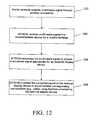
- FIG. 12is a flow diagram illustrating an embodiment of a process including mobile terminal signal conversion.
- FIG. 13is a schematic diagram illustrating another example of a system in which mobile terminal signal conversion may reside.
- FIG. 14is a schematic diagram illustrating still another example of a system in which mobile terminal signal conversion may reside.
- FIG. 15is a schematic diagram illustrating examples of mobile terminal signal conversion applications.
- FIG. 16is a schematic diagram illustrating a control system of multimedia communications of different user terminals.
- FIG. 17is a flow diagram illustrating an example of directing a television to display content using signals received from a remote location through a cellular communications network.
- FIG. 18is a flow diagram illustrating an example of converting and routing multimedia content to different terminals.
- FIG. 19is a flow diagram illustrating an example of bidirectional operation involving transmitting and routing multimedia content into and out of the home.
- FIG. 20is a flow diagram illustrating an example of receiving and accommodating completion of multimedia content requests corresponding to different sources.
- Internet contentis requested and accessed by cellular users in correlation with their determined location. Provision of Internet content is customized according to location, and provided in a series of locally customized networks.
- a given local networkincludes servers configured to include content believed appropriate for its location. The delivery of content is made from a particular local network configured as such, to a user's cellular phone through the local base station.
- information about Hollywoodmay be accessed through cellular network base station(s) in the Hollywood area, when the cellular user is detected as being proximate to the Hollywood area.
- These base stationsdeliver Internet content that is relevant to the area, such as web sites about film and movie stars.
- This Internet contentis stored in servers that the base stations covering the area can access conveniently to provide faster and more efficient transmission to the cellular users in the service area.
- this inventionenables an optimum data flow for cellular users to access rich information and data of all kinds from the Internet.
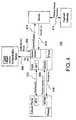
- FIG. 1is a block diagram illustrating a system 100 configured to provide Internet content delivery in accordance with the present invention.
- the basic elements of the system 100are the User Equipment (UE) 110 , the Radio Access Network (RAN) 120 , the Core Cellular Network (CCN) 130 , the External Network (EN) 140 , and the Local Customized Network (LCN) 150 .
- UEUser Equipment
- RANRadio Access Network
- CCNCore Cellular Network
- ENExternal Network
- LPNLocal Customized Network
- the UE 110is a cellular phone configured to communicate with base station(s) of the RAN 120 .
- the UE 110is preferably a cellular phone, it should be understood that a variety of devices may be equipped with same communication functionality.
- Other examples of the UE 110include a Personal Digital Assistant (PDA), Set Top Box, Kiosk, or any personal computing device configured to include the wireless communication capability.
- PDAPersonal Digital Assistant
- KioskKiosk
- any personal computing deviceconfigured to include the wireless communication capability.
- the RAN 120 and CCN 130preferably implement conventional elements of a cellular network and are described further as follows.
- the RAN 120includes Base Station and Radio Network Controller (RNC) elements.
- the Base Stationprovides resource management and provides an interface that converts the data flow between the UE 110 and RNC.
- the RNCcontrols radio resources for the Base Stations to which it is connected, and also manages connections to the UE 110 .
- the CCN 130is connected with the EN 140 .
- the most notable examples of the EN 140can be grouped into two kinds: Circuit Switched (CS) 142 networks and Packet Switched (PS) 144 networks.
- the CS 142 networkprovides circuit-switched connections for circuit-switched services, such as telephony and ISDN.
- the PS 144 networkprovides connections for package data services.
- the Internetis a significant and notable application of a PS network.
- the CCN 130comprises MSC/VLR, GMSC, HLR, SGSN and GGSN elements.
- the HLRHome Location Register
- the service profileincludes information including allowed services, roaming areas, forwarding numbers and the like.
- the HLRstores the UE 110 location to accommodate that routing of calls and other information to the UE 110 .
- the MSC/VLRMobile Services Switching Center and Visitor Location Register respectively provide switch operations and a database for the UE in its current location for Circuit Switch (CS) services.
- the VLRstores the user's service profile, as well as more precise information on the UE's location within the serving system.
- CS connectionsgo through the GMSC (Gateway MSC), which is the switch at the point of connection to the external CS network.
- the SGSN(Serving GPRS (General Packet Radio Service) Support Node) functionality is similar to that of MSC/VLR but is typically used for Packet Switch (PS) service. PS connections go through the GGSN (Gateway GPRS Support Node).
- GGSNGateway GPRS Support Node
- the LCN 150comprises one or more computing devices configured to include memory, processing capability, and interfaces to provide the functionality described herein.
- the LCN 150includes local servers that are configured to provide custom Internet content.
- the LCN 150is also configured to include a content access monitoring module, which monitors Internet access and determines content applicable to the designated location of the LCN 150 .
- the LCN 150thus performs monitoring and caching related to locally applicable content.
- the monitoringincludes local access, which determines which content users in the location are accessing.
- the LCN 150maintains a cache of locally applicable Internet content, which includes refreshing to add new content and remove stale content as determined by information received from the monitoring functionality.
- One technique for determining whether content is locally applicableis measuring access frequency. If many users in the location are determined to be accessing particular Internet content, then that particular Internet content is determined to be locally applicable and is included in the cache during the next update.
- the LCN 150is configured to be logically proximate to the base station(s) of the cellular network at the particular location.
- logical proximityis carried out by having the LCN 150 physically proximate to the relevant base station(s), such as in the same geographical area.
- the LCN 150may be located in a metropolitan area or within an area the covers certain zip code(s) of a metropolitan area.
- Logical proximitymay alternatively be carried out without requiring physical proximity. This, for example, may be done by providing dedicated resources including a high bandwidth connection between the LCN 150 and the local users.
- the LCN 150is configured to deliver locally applicable content more efficiently and rapidly because of the dedicated resources, without necessarily requiring physical proximity.
- the locally applicable content for a given LCNis organized in a layered architecture.
- a “first layer” of contentis considered to be the content that has the highest local applicability. Additional layers are also provided upon the first layer, with succeeding layers progressively covering larger geographical areas (i.e., progressively larger numbers of base stations).
- the layeringinvolves communication with neighboring LCNs covering increasing areas, to determine the content that is locally applicable for the additional levels.
- a first layercorresponds to locally applicable content at a first level of granularity (e.g., as monitored/determined only for the location of the LCN or a small local group of LCNs)
- a second layercorresponds to locally applicable content at a second level of granularity (e.g., the logical “AND” or intersection of content that is frequently accessed across a larger area as determined by the monitoring of access for several LCNs in the defined larger area, and so on.
- the operation of the system to update the LCN accordinglyis described as follows, with concurrent reference to FIG. 1 and the flow diagram of FIG. 2 .
- the processcommences by monitoring 202 Internet content accessed by users for a current location. This is done by monitoring the gateway of the connection between the CCN 140 and PS 144 networks to track the Internet content accessed by the cellular users.
- the monitored contentmay have two useful purposes. One is to accommodate the delivery of locally applicable content, which may be determined by frequency of access for the given location. Another is to allow the providers of content (e.g., merchants or other commercial entities) to receive an indication which content is locally applicable. This allows the providers of content to assist or participate further in determining what is locally applicable. For example, a merchant provided with an indication of local applicability for certain content may wish to make advertisements, coupons, or the like available to the users in that domain.
- providers of contente.g., merchants or other commercial entities
- determination(s) 204 of the base station(s) from which requests for the Internet content are mademay be performed by checking the VLR and HLR to discover the base stations from which the requests for the Internet content are sent from through. It is noted that base station discovery is just one way that physical location may be determined. Other examples include but are not limited to using GPS, zip code, telephone number, and IP address information to make the determinations.
- the next stepcomprises determining 206 locally applicable content based upon the monitoring 202 and determination(s) 204 of the base station(s). Determination of local applicability is performed by determining access frequency. Alternatively, local applicability may be determined by comparing the location of the requesting user (base station) to a location that is identified in association with the requested content.
- the contentis loaded 208 in servers that are logically proximate to users for the given location.
- Thismay be done by placing the current (e.g., first) layer server(s) loaded with the Internet content and/or other information/data to achieve an optimum and faster data transmission for the cellular users to access the data stored in the servers through the base stations.
- the serverscan be placed logically close to the base station through which the cellular users access the data stored in the server(s).
- steps 202 - 208are performed to load the next 212 (e.g., second) layer server(s) with locally applicable content. As described, this preferably entails a broader geographical area as the layers increase. The process continues until it is determined 210 that no more layers need to be determined and loaded.
- the number of layers in a given systemwill vary according to application, and as desired. Layering will typically involve a trade-off between maximizing locally available content and the processing resources required to generate and manage layers for progressively broader areas.
- the content that is loaded into the base station(s)may be refreshed 214 on any desired schedule or trigger.
- the process described aboverepeats, starting again with the first layer.
- Content that is stale or otherwise determined to no longer be locally applicablemay be removed, and of course new content may be added during a refresh cycle.
- Additional serversmay be added vertically and/or horizontally as desired.
- Verticallymeans that servers may be added at a given physical location to cover first, second, third, etc. layers.
- Horizontallyrefers to adding different sets of servers corresponding to different locations (i.e., one set for the first layer, a second set for the second layer, and so on).
- a regular schedule or certain amount of activitycan be used to trigger a refresh of the layering.
- the Internet content in the LCN 150 serversis modified according to the updated findings on the requests for the Internet content sent from the base stations.
- the Internet content stored in the serversis refreshed at a proper time, such as when the servers are not overwhelmed by the users accessing the contents.
- the serversare thus loaded with the information for broadcast and/or multicast and/or any data to be accessed by the cellular users for an optimum transmission to the users in service areas.
- the locally applicable contentmay be sent and delivered upon request to the users.
- Examples of communication pathways for sending the locally applicable Internet contentinclude the relatively direct pathway through the RAN 120 , the pathway through the CCN 130 and then the RAN 120 , or others.
- a variety of techniquesmay be used to implement the locally applicable content cached by the LCN 150 in conjunction with requests for Internet content by UE 110 (or other device) users.
- the UE 110 request for Internet contentprompts an initial check for content in the locally applicable content, followed by conventional Internet access should the content prove to be absent from the locally applicable content that is currently cached.
- the first attempt to satisfy the requestmay be made from the first layer, followed by the second layer, and so on.
- the number of layers searched to respond to a particular requestmay vary as desired. When the number of layers designated to be searched for the current request is exhausted, conventional Internet access is used to retrieve content related to the request.
- Various cache management and network optimization techniquesmay be used to manage the locally applicable content.
- fully associative (FA), direct mapped (DM), and set associative (SA) mechanismsare examples of techniques that can be used to determine where a specific content can be stored on the server.
- techniques to ensure block validity and to manage cache hits and missescan also be used.
- Random, LRU (Least Recently Used) and FIFO (First In First Out) block replacement schemesare among those that can be used to manage the blocks in the cache.
- the present inventionfacilitates a systematical solution for mobile payment (or the communication of other information, as well as the receipt of information such as alerts).
- this aspect of the present inventionimplements a cellular network, a wireless personal area network (WPAN) and wireless identification technology.
- WPANwireless personal area network
- Various technologiesmay be used for these components, including but not limited to 3G technology for the cellular network; Zigbee, Bluetooth, or UWB technologies for the WPAN; and RFID (e.g., NFC) for the wireless identification technology.
- FIG. 3illustrates an example of a system 300 that implements this aspect of the present invention.
- the system 300includes a user equipment (e.g., cellular phone, PDA, etc.) 310 and wireless HUB 320 , which is connected to servers 330 through a network 340 , such as the Internet.
- a user equipmente.g., cellular phone, PDA, etc.
- wireless HUB 320which is connected to servers 330 through a network 340 , such as the Internet.
- the wireless HUB (WHUB) 320may be located in a public or private location.
- the WHUB 320is preferably housed in a kiosk.
- the kioskmay be located on a street, or in an airport, shopping mall, or any location that is perceived as convenient and likely to include user traffic.
- the WHUB 320is preferably configured for usage in locations like homes or hotel rooms. In these environments, the WHUB 320 may be provided in a smaller device such as part of a Set Top Box (STB).
- STBSet Top Box
- the handset 310is equipped with a tag that provides a unique identifier that can be wirelessly communicated to the WHUB 320 .
- a preferred tagis a Near Field Communication (NFC) tag 312 .
- NFCprovides short-range wireless connectivity that uses magnetic field induction to enable communication between the devices. It has a short range of a few centimeters, which is believed to be advantageous for applications of this aspect of the present invention. Although NFC is preferred, RFID or other substitutes may also be provided.
- the handset 310also includes a WPAN transceiver 314 , which allows additional communication channel between the handset and the WHUB 320 .
- the wireless WHUB 320is similarly equipped with an NFC reader 322 , a WPAN transceiver 324 and a network adaptor 326 .
- the NFC technologyaccommodates secure and automatic authentication and data exchange between the NFC tag and NFC reader.
- the NFCis uniquely associated with other information that allows the appropriate action (payment, alert, etc.) to take place.
- the RFID tagis associated with the user's bank account.
- a second secure communication channel with more capabilitiesis established between the handset 310 and WHUB 320 . This allows the action request and related communications to be reliably transmitted between the two devices.
- a secure wireless connection between the handset 310 and WHUB 320is established.
- This communicationcan implement the WPAN transceiver, which has a higher data rate and longer operational range compared to NFC.
- the secure communicationallows the exchange of additional information related to the action, such as price and credit card information for a purchase request and corresponding payment scenario, to be sent between the handset 310 and the WHUB 320 .
- the secure communicationcan be implemented by hardware (e.g., a dedicated hardware chipset) and software (e.g., data encryption algorithm).
- the WHUB 320can also exchange data with other WPAN devices 350 . It may be useful for the WHUB 320 to communicate with these devices 340 to exchange information related to the action. For example, the WHUB 320 may collect water usage information from a water meter equipped with the WPAN device 340 functionality. This data may be stored locally by the WHUB 320 , or may be transmitted to the appropriate server 330 through the network connection 350 . The data does not necessarily need to be collected by the WHUB 320 concurrently with the user-requested action. For example, the acquisition and transmission of water usage information may occur periodically, and separate from the user's request to make a corresponding payment.
- the WHUB 320may optionally be configured with a wireless communication capability such as that provided in a cellular phone.
- the WHUB 320is thus configurable to operate with a system that delivers locally applicable Internet content as described above in connection with FIGS. 1 and 2 .
- FIG. 4further illustrates and provides an example of a payment process 400 in accordance with this aspect of the present invention.
- the process 400initiates with an authentication 402 process that accommodates recognition and identification of the handset by the wireless WHUB via the NFC tag.
- the communication through the separate secure communication channel(e.g., WPAN) is then established.
- the WPAN functionalityis used to communicate between the handset and the WHUB, so that content related to a requested action may be securely exchanged.
- the requested actionis a purchase request 404 .
- the actionmay or may not immediately follow authentication 402 .
- the cellular phonemay be configured to include browsing capability, which allows that interface of the cellular phone to be used to review items prior to making a purchase request.
- Various purchase typesmay be made with the purchase request. Examples may include a physical item that is separately shipped to an address, a download that is made available immediately, possibly to the cellular phone, a service, etc.
- Internet contentmay be accessed by the cellular phone in association with an action request.
- One example of providing content to the cellular phonemay be the locally applicable Internet content as described above in connection with FIGS. 1-2 .
- the cellular phonemay access Internet content through channels other than through the WHUB.
- Actionsinclude but are not limited to bill payment, populating an account with funds, online shopping transactions, and others.
- the process of authenticationmay be based upon a Tag ID and password.
- the Tag ID and passwordare sent 406 to the authentication server, which then returns a notification 408 confirming authentication.
- this authenticationindicates whether the individual is who he or she claims to be, but does not address the access rights of the individual.
- the authentication servermay reside within or outside the WHUB.
- additional informationmay also be required in association with a requested action.
- account identification information or passwords to access an online accountmay be required by an external server.
- the external serversends a request to the WHUB for the information.
- the WHUBmay store such information and respond to such a request.
- the WHUBmay further exchange information with the user (through the handset), in order to obtain the additional information requested by the external server.
- a payment request 410is made between the WHUB and external server through the network connection.
- the payment request 410allows the user to complete the transaction related to the purchase request 404 .
- the servercorresponds with a payment gateway, and a resolution 412 indicating whether the payment request succeeds or fails follows.
- the WHUBUpon an indication of a successful payment request, the WHUB receives 414 a receipt or confirmation number from the external server relating to the requested action, and passes 416 that and/or related information to the handset confirming completion of the action. This may be a receipt, confirmation numbers, coupon codes, or the like.
- the present inventionprovides for wireless management of tasks and corresponding alerts.
- One such taskis diaper management, which is described in detail as follows.
- This aspect of the present inventionaccommodates task management based upon wireless delivery of alerts to overcome the problem of estimating when the task requires completion.
- alert based tasksinclude but are not limited to diaper management.
- home security monitoringmay also be accommodated.
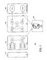
- FIG. 5illustrates an example of a diaper management system 510 according to the present invention.
- the diaper management system 500includes a diaper condition sensing module 510 and a central receiver/controller (CRC) 520 .
- the CRC 520operates on a conventional processing platform, and is configured to communicate wirelessly with the diaper condition sensing module 510 .
- the CRC 520also includes a network interface. The wireless and/or network interface accommodate the transmission of appropriate alerts to caregivers.
- the diaper condition sensing module 510includes a sensor 512 and a transmitter 514 .
- the sensor 512is configured to monitor one or more of the following conditions, whose results indicate whether the diaper is wet or not:
- the weight of the diaper—urine or fecesmake the diaper heavier than a dry and clean diaper
- Fecesthe solid waste material; the bilirubin, or stercobilinogens in the feces; the specific food decomposed material including starch, fat, plant fiber, muscle fiber and so on; and/or
- the sensor 512triggers the transmitter 514 to establish a wireless communication channel between itself and the CRC 520 .
- a signalis sent by the transmitter 514 to inform the CRC 520 that the diaper is wet.
- This wireless communication channelpreferably uses wireless technologies such as UWB, Bluetooth, RFID, Spread Spectrum, or other conventional wireless communication technologies.
- Each sensor 512preferably has a unique ID.
- Multiple access mechanismssuch as TDMA, CDMA, FDMA, or other conventional approaches, may also be applied to allow the central receiver to communicate with multiple sensors at the same resource. It is believed that Zigbee/Bluetooth may be useful for many applications in light of the competing demands of working range, data rate and cost.
- the receivertriggers sound, light, text and/or other indications of the status of the diaper. These indications may be variously displayed, broadcasted, reflected, etc. through speakers, telephones, pagers, beepers, computers, and so on to inform the caregiver(s) so that they can remedy the situation.
- the diaper condition sensing module 510may be variously provided. One example connects to the diaper using a probe that measures for desired criteria as described above and as shown in FIG. 5 .
- the diaper condition sensing module 510provides the diaper condition sensing module 510 within the diaper.
- the sensor 512also includes interfaces (probes) for measuring the desired criteria, within the confines of the diaper.
- the transmitter 514may use various communication techniques as described above.
- the functionmay be provided by causing the circuit loop of the RFID tag to transition from open to close when the diaper condition (e.g., wet) is detected by the sensor, which automatically causes the ID Tag to be sensed by the tag reader of the CRC.
- the diaper condition sensing module 510may be placed within a diaper and reused. Diapers may be configured with pouches or the like to allow the placement of the diaper condition sensing module 510 .
- the diaper condition sensing module 510is manufactured and sold as an integrated part of each diaper, so that caregivers do not have to be concerned about the placement of the module 510 each time a diaper is changed.
- a diaper management systemmay be configured to manage the diapers for groups of children, such as a pre-school class or a day care facility where many children may potentially wear diapers.
- An example of such a system 600is shown in FIG. 6 .
- the CRC 620is configured to distinguish children in need of new diapers from those that are not and respectively sends messages to appropriate caregivers.
- the CRC 620is equipped with a database that associates the unique identifier corresponding to each diaper condition sensing module 610 a - g to at least one contact party.
- Alternative communication pathwaysphone, e-mail, etc.), multiple contacts (caregiver#1, caregiver#2), and various other information may be associated to a given diaper condition sensing module 610 a - i in the database.
- the CRC 620In addition to providing a status alert about the condition of the diaper, the CRC 620 also determines the location of the diaper by using wireless location techniques, including but not limited to Angle of Arrival, Time of Arrival, and Received Signal Strength Indication. This allows the option of also giving the designated caregiver information about the location of the child having the soiled diaper.
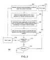
- FIG. 7is a flow diagram illustrating a process 700 for sending a caregiver alert according to a diaper condition in accordance with the present invention.
- the process 700commences with the DCSM sensor monitoring 702 the diaper condition.
- the DCSM sensordetects the updated condition of the diaper.
- the DCSM transmittersends 704 the diaper condition update to the CRC.
- the CRCreceives 706 the update and corresponding indications. Many conditions may be updated and the DCSM and CRC are configured to communicate them accordingly.
- the CRConce provided with the update, proceeds to estimate the location of the (e.g., wet) diaper.
- the DCSMsends an ID corresponding to the update, which identifies the diaper/child.
- the CRCqueries its database and thus matches 708 the ID corresponding to the update to tailor caregiver alert(s). These alerts are then sent 710 to the caregiver(s) accordingly.
- the CRC provided alertmay be to a PC having a display screen with a map of the room(s) and the estimated location of the wet diaper.
- Other CRC provided alertsmay merely notify additional caregiver(s) as to the status of the diaper, without the location, so that the additional caregiver(s) may be apprised of the status.
- the CRCmay also poll the DCSM after a given period of time to ensure that the diaper condition has been updated.
- the CRCmay be configured with configuration settings that allow a caregiver to specify when and how they should be updated.
- the parentmay configure the CRC not to send an alert to them when the diaper is first detected as being wet, but to wait until a certain period of time elapses.
- the baby-sitter alertmay be provided immediately. If the certain period of time passes and the diaper remains wet, the CRC can then notify the parent about the diaper condition, and the parent will realize that the diaper has not been changed.
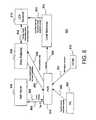
- FIG. 8is a block and event diagram illustrating an example of a system 800 that implements several aspects of the invention described above.
- the system 800includes UE 802 , WHUB 804 , Authorization Server 806 , Base Station(s) 808 , LCN Server(s) 810 and DCSM 812 , which respectively provide the functionality described above for the components having the same names.
- the WHUB 804in addition to being configured to facilitate secure receipt and performance of an action such as a purchase request and corresponding payment request, includes the CRC functionality that allows a response to diaper condition update as provided by the DCSM 712 (the diaper being just one example of an item for which updates may be provided).
- the delivery of locally applicable Internet contentmay be provided in conjunction with the diaper update.
- a local merchant (and corresponding server) 814 that sells diapersis able to present a coupon or other incentive to the user in conjunction with the determination that a diaper is wet by the DCSM 812 .
- the WHUB 804may keep a database of household requirements and inventories. For example, the WHUB 804 may monitor the number of diapers detected as being used. When the amount of used diapers is close to the amount known to have been purchased previously, an additional alert may be presented to the user so that they are aware that they need diapers and they can get the discount if they buy brand x based upon the information provided by the local merchant.
- the process for providing such functionalitymay be as follows. Based upon historical activity relating to access of locally applicable Internet content, as well as whatever merchant participation is desired in conjunction with the system 800 , the local merchant's information is cached 852 at the relevant LCN Server(s). A wet diaper is detected 854 by the DCSM 812 and this information is transmitted to the WHUB 804 . The WHUB 804 , managing the diaper inventory for the household, determines that the inventory of diapers is low, and thus sends 856 a purchase alert through the Base Station 808 requesting information related to the current need. In response to this, the LCN Server(s) 810 determine that the local merchant information is relevant to the current need, and thus retrieve 858 and send 860 the cached local merchant information to the WHUB 804 .
- alerts of both the diaper condition and the low diaper inventorymay be provided and retained for user review.
- This purchase requestmay be made by directly interfacing with the WHUB 804 , or by using the UE 802 in the fashion described above. The latter option is shown.
- the UE 802sends 862 its Tag ID and purchase request to the WHUB 804 . This, of course, may follow some browsing activity prior to the purchase request, so as to review the possible purchase options.
- the authenticationmay be as described above, based upon a Tag ID and password.
- the Tag ID and passwordare sent 864 to the authentication server, which returns a notification 868 confirming authentication.
- the WHUBwill have provided (or the Local Merchant may already have) the shipping address. Additionally, if the Local Merchant is a provider of several items (such as a supermarket), then items may be accumulated prior to completing a purchase and/or making a shipment and/or making the products available for pick up by the user.
- the WHUBis preferably configured with a shopping list that allows organization of periodic cumulative purchases to accommodate this functionality.
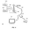
- FIG. 9is a schematic diagram illustrating an example of a system 900 with mobile terminal signal conversion.
- Mobile terminal signal conversionaccommodates displaying the high rate data flow multimedia information available in a wireless communication environment in an external device, which allows true realization and enjoyment of the benefits of the multimedia content.
- the multimedia informationis provided to a wireless mobile terminal using so-called next generation cellular technology (i.e., 3G and 4G), which can be employed in transmitting multimedia information (e.g., rich graphics, real-time audio/video).
- multimedia informatione.g., rich graphics, real-time audio/video.
- 3G and 4Gnext generation cellular technology
- Mobile terminal signal conversionmakes usage of a separate multimedia display terminal including but not limited to a monitor, television set, projector, or LCD display. These displays typically have video and audio reproduction capabilities that are superior to those found on mobile terminals. They also use a power supply that is separate from the mobile terminal.
- multimedia informationmay be provided by any number of service providers 902 a - b and delivered through a network 904 to a base station 906 to ultimately accommodate transmission of the multimedia information, among other things, to a cellular phone 908 .
- This system 900is provided by way of example, and it should be understood that any conventional or to-be-developed technology for delivering voice and/or data to mobile terminals may be provided.
- These wireless communication networksinclude but are not limited to a cellular communications network or a wireless local area network.
- a typical external display system 914This may also be variously provided and may be digital or analog. Examples of digital Systems include HDTV, LCD and plasma. Examples of analog Systems include television sets that implement standards such as NTSC, PAL, SECAM, and analog computer monitors (SVGA, VGA).
- the external display system 914does not have the size constraints of the display screen on the cellular phone 908 and is preferably powered independently.
- a mobile terminal signal conversion module (MTSCM) 912resides within a separate housing 910 , outside the cellular phone 908 .
- MTSCM 912The functionality of the MTSCM 912 is now further described with concurrent reference to FIG. 9 and the flow diagram of FIG. 12 .
- the MTSCM 912processes signals to accommodate reproduction by an external device. Specifically, a multimedia signal is transmitted to the cellular phone 908 through the wireless communications network as previously described (step 1202 ).
- the multimedia signalmay include a video signal intended for reproduction by the cellular phone 908 , using the cellular phone display screen.
- processing of a video signalis described, although it should be understood that any multimedia signal or component thereof may be converted in accordance with the present invention.
- the cellular phone 908is connected to the MTSCM 910 . This may be accommodated by a cable connection that interfaces the cellular phone 908 to the MTSCM 912 housing 910 . Through this connection, the MTSCM 912 receives the video signal from the cellular phone 908 (step 1204 ). The video signal as received may be configured to accommodate a video display on the screen provided by the cellular phone 908 .
- the cable connectionis an example of a wired connection interfacing the cellular phone 908 to the MTSCM 912 .
- An alternative wired connectionis a seat that directly interfaces the two without a cable.
- a wireless connectionmay also be provided, although it may currently be less practical to provide than the wired connection because of the potential for high throughput rate requirements.
- the wireless connectionmay also implement any conventional known technology including but not limited to a Bluetooth connection.
- the MTSCM 912processes the video signal to provide a converted video signal that has a display format and/or signal power level appropriate for an external display terminal 914 that is separate from the cellular phone 908 (step 1206 ).
- the display format and/or signal power level of the external display terminal 914may be different from that of the cellular phone 908 but there may also be embodiments where the format is the same. Even if the formats are the same, conversion of the signals to accommodate display on the external display terminal 914 would still be implemented to adjust the power level for driving the external display, and possibly to minimize throughput requirements. This signal conversion is described further with reference to FIGS. 10 and 11 , below.
- the MTSCM 912provides the converted video signal to the external display terminal 914 to accommodate the corresponding video display on a screen provided by the external display terminal 914 (step 1208 ). This may be accommodated through a connection between the MTSCM 912 housing 910 and the external display terminal 914 as shown.
- mobile terminalrefers to typically handheld mobile devices such as cellular phones and personal digital assistants. Although these devices include an execution platform as well as input and display capabilities, such devices are distinguished from personal computers, such as desktop or laptop computers, which are not designed for convenient handheld usage.
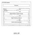
- FIG. 10is a block diagram illustrating an example of an MTSCM 1000 in accordance with the present invention.
- the MTSCM 1000may be provided as software, firmware, hardware, or any combination thereof.
- the MTSCM 1000operates in the context of an execution platform. That is, the MTSCM 1000 includes instructions that are stored in memory for execution by a processor. Any conventional or to-be-developed execution platform may be used.
- the processor, memory, and related elements such as a power supplyare well known and need not be described herein to convey an understanding of the invention.
- FIG. 10illustrates one modular breakdown for the components of the MTSCM 1000 . It should be understood that the described functionality may alternatively be provided by an MTSCM having fewer, greater, or differently named modules from those illustrated in the figure.
- modules as shown to reside in a common locationit is noted that the functionality may reside in separate components of a system that includes a mobile terminal, an external monitor, and (optionally) an intermediate device housing the MTSCM and interfacing the mobile terminal and external monitor.
- the overall functionality of the MTSCMmay be separated such that portions of the overall functionality are respectively provided by the mobile terminal, separate intermediate housing, and/or the external display device.
- the MTSCM 1000may also be provided in the form of a chipset, configured for inclusion in a mobile terminal, dedicated separate signal conversion device, or external display terminal, and to provide the described mobile terminal signal conversion functionality.
- the MTSCM 1000includes a mobile terminal interface module 1002 , a signal conversion module 1004 , and an external device interface module 1006 .
- the mobile terminal interface module 1002accommodates receiving the multimedia signal from the mobile terminal.
- a conventional physical interfaceprovides a connection between the MTSCM 1000 and the mobile terminal through which the signals flow to the MTSCM 1000 .
- the mobile terminal interface module 1002recognizes the multimedia signal and stores the signal for processing by the remaining modules. Buffering and the like may be implemented to accommodate storage and signal processing, as described further below.
- the signal conversion module 1004is in communication with the mobile terminal interface module 1002 and thus accesses the received multimedia signal.
- the signal conversion module 1004recognizes the multimedia signal format, and processes the multimedia signal to provide a converted signal.
- the converted signalmay have a format and a signal power level that differs from the one used by the mobile terminal, as appropriate for one or more types of external devices to which the MTSCM 1000 is connected.
- Various examples of the type of devices to which the MTSCM 1000 may be connectedare illustrated and described in connection with FIG. 11 , below.
- the external device interface 1006is in communication with the signal conversion module 1004 and thus accesses the converted signal.
- the external device interface 1006also allows connection to the external (e.g., display) device.
- the external device interface 1006may provide both the feeding of the converted signal to the external device, and driving the external device. Alternatively, the external device interface 1006 may merely feed the converted signal to the external device, with the external device including internal elements for driving its signal reproduction (e.g., display) facilities.
- FIG. 11is a block diagram illustrating another example of the MTSCM 100 .
- the MTSCM 1100includes additional detail regarding the signal conversion aspect, and illustrates examples of differing types of external devices to which the MTSCM 100 may provide converted signals.
- the illustration and corresponding descriptionare provided by way of example. Although numerous connections are illustrated, it should be understood that the present invention may be practiced in the context of providing as few as one, and as many as all of the listed connections. It should also be understood that there may be additional examples that are not listed herein, but which are encompassed by the teachings described herein.
- the MTSCM 1100includes an interface/buffer module 1102 that is analogous to the previously described mobile terminal interface module.
- the buffer and interfacingare configured to accommodate signal processing by the remaining elements in support of the requirements and expectations of users of the multimedia signal output (e.g., adequate buffering and processing rate to provide real time audio/video).
- the mobile terminal video compression formatmay of course vary, but currently the most likely format is MPEG-1 or MPEG-2. Buffering and throughput rate may also be provided as desired by the designer. Currently, it is believed that 200 Mb is an adequate buffer size, although buffers of 500 Mb or more may of course be provided. Additionally, a throughput rate of approximately 10 Gb/s will be adequate for many current Systems, but may be increased as demands and technology evolve.
- the Video Compress Decoder 1104 areceives the multimedia signal.
- the multimedia signalis typically provided in a compressed format to accommodate increased signal transfer rates.
- An example of a compression schemeis that provided by one of the MPEG standards (e.g. MPEG-1, MPEG-2, MPEG-4).
- the Video Compress Decoder 1104 ais configured to include the appropriate compression/decompression (CODEC) module to accommodate decompression of the received multimedia signal.
- CODECcompression/decompression
- Video Compress Decoder 1104 ain the MTSCM 1100 , the functionality may be provided within the cellular phone or other mobile terminal. However, this may be less practical because of the high bandwidth that would be required between the cellular phone and the MTSCM 1100 to deliver the decompressed signal, and the corresponding likelihood of a larger buffer requirement for the MTSCM 1100 .
- the Video Compress Decoder 1104 aoutputs a decompressed digital multimedia signal that is passed to the Digital/Analog Video Encoder (DAVE) 1104 b and/or the Digital/Digital Video Encoder (DDVE) 1104 c .
- the DAVE 1104 bis configured to prepare signals for analog external display terminals 1120
- the DDVE 1104 cis configured to prepare signals for digital external display terminals 1122 .
- the DAVE 1104 b and DDVE 1104 crespectively receive the decompressed multimedia signal and convert the signals to the format(s) and signal power level(s) required for the terminals to which they interface.
- Examples of formats used by analog display terminals 1120include S-video, RGBHV, RGBS, and EIA770.3 as illustrated.
- the DDVE 1104 cprovides output using standards such as DVI, DVI-D, HDMI, and IEEE1394.
- the signals respectively provided by the DAVE 1104 b and DDVE 1104 care provided to the terminals through conventional interfaces 1106 a - b .
- the DAVE 1104 b functionalitymay be embodied as a video card that is configured accordingly. Examples of video cards that may be configured to provide the described functionality include but are not limited to the Diamond Stealth S60, ASUS V9400-X, or RADEON 7000.
- the signalsare used to provide a display on the external display, as required according to the particular type of display.
- the video data streammay be a digital RGB signal which represents the intensity of the red, green and blue light respectively at different position.
- This signalis converted to analog by a D/A converter.
- This converted analog signalis quantified to the voltage and format required by the standard, such as the input of cathode-ray-tube (CRT) monitor.
- CRTcathode-ray-tube
- This standard video signalwill drive a set of electron guns, which produce a controlled stream of electrons to display of red, green and blue light respectively on a CRT screen.
- This is but one example and the present inventionis not limited to a particular technology (e.g., CRT) for the external display.
- the MTSCMmay be independently housed separately from both the mobile terminal and external display terminal, with respective connections to the other devices to provide a system configuration that includes the three pieces of hardware (mobile terminal, conversion box, external display terminal).
- This configurationprovides the flexibility of allowing any standard mobile terminal and/or display to be potentially interface with the MTSCM without imposing constraints on the mobile terminal or external display terminal manufacturers.
- a possible drawback to this configurationis that additional hardware is introduced into the system.
- FIG. 13is a schematic diagram illustrates an example of a system 1300 in which the MTSCM mobile terminal signal conversion may reside within the mobile terminal 1308 .
- the components and functionality of the service providers 1302 a,b network 1304 and base station 1306 for delivering multimedia signals to the mobile terminal 1308is the same as for the analogous elements of FIG. 9 and need not be re-described.
- the external display terminal 1314may be any of the various types named above.
- the MTSCM 1312provides the same functionality described above. However, in contrast to residence in a separate housing, the MTSCM 1312 is a component of the mobile terminal 1308 .
- a potential advantage of this system 1300is that, again, any standard equipment can serve as an external display terminal 1314 , without a constraint on the display manufacturer. Additionally, only a simple wired or wireless interface is required to connect the external display with the mobile terminal 1308 . This means, for example, that the user will not be required to carry a bulky conversion module in addition to their cellular phone.
- a potential drawback to this system 1300is that the execution platform of the mobile terminal 1308 may be designed to accommodate only traditional functionality, so for some Systems it may be challenging to add the MTSCM functionality to the existing platform. Additionally, the MTSCM will consume power that may unduly exhaust the limited power supply offered by the mobile terminal 1308 battery. It is useful for this embodiment to provide power to the mobile terminal 1308 through the cable connection to the external display terminal 1314 , but again this may require modification to the mobile terminal 1308 as the existing charger interface may be insufficient.
- FIG. 14is a schematic diagram illustrating another example of a system 1400 , in which the MTSCM 1412 resides within the external display terminal 1414 .
- the components and functionality of the service providers 1402 a,b network 1404 and base station 1406 for delivering multimedia signals to the mobile terminal 1408is the same as for the analogous elements of FIG. 9 and need not be re-described.
- the mobile terminal 1408need only be connected directly to the external display terminal 1414 .
- the MTSCM 1412 functionalityreside within the mobile terminal 1408 , it is part of the external display terminal 1414 .
- the power supply and execution platform issues associated with placing the MTSCM 1414 in the mobile terminalare resolved with this system 1400 , and any mobile terminal 1408 can potentially be connected to any MTSCM-ready external display without requiring modification, other than provision of an output interface.
- a potential drawback of this configurationis that it adds a component to the standard external display terminal, and corresponding costs.
- FIG. 15is a schematic diagram illustrating examples of mobile terminal signal conversion applications 1500 in accordance with the present invention. These applications 1500 are provided by way of example, to give the reader an understanding of the potential contexts in which embodiments of the present invention may operate. The present invention is not limited to the disclosed applications, nor are all potential applications required for any given embodiment.
- the basic architecture for provision of the wireless communications signal and corresponding multimedia signalis as described above for the service providers 1502 a - b , network 1504 , base station 1506 and mobile terminal 1508 .
- the MTSCM 1510may be separate or reside in the mobile terminal 1508 or display terminal 1512 .
- Examples of applications 1514 where a larger screen and potentially superior audio may be enjoyedinclude video conference, HDTV, games, GPS, and video on demand.
- embodiments of the present inventionwill accommodate enjoyment of full multimedia capability in locations 716 including vehicles, airports, hotels and remote resorts.
- the present inventionaccommodates usage inside a vehicle, a plane or any type of transportation, enabling the passenger to browse the Internet, watch TV, play games, participate in a video conference or call, and work on all sorts of software with full functionality.
- FIG. 16is a schematic diagram illustrating a control system for multimedia communications between different user terminals.
- a converting serverthat is variously positioned in network environments provides a routing function and a connecting function, and functions bi-directionally. Accordingly, this aspect provides for the transmission and receipt of content and converts such content in both directions depending upon the connected devices and corresponding protocols used by such devices.
- cellular television functionalityis provided.
- a television in form and functionalityalso includes cellular communication features as well as the above-described conversion functionalities.
- one or more “channels” corresponding to the cellular applicationare provided in the cellular television so that the content received in this fashion may be accessed and viewed by a user in a fashion similar to that used for accessing traditional television channels.
- one or more embodiments of the inventionprovide efficient integration for Internet, wireless networks, cable, DSL, satellite, and TV communications to enable communications among potentially different user terminals.
- the user terminalsinclude home and office appliances (such as TV, computer) and wireless terminals (such as mobile phone, PDA).
- a Management Center (MC) Systemreceives, selects, converts, compresses, decompresses, and routs data to the user terminals.
- MCManagement Center
- signalssuch as those from a fire alarm or theft sensor are sent through the MC System to a user's cell phone and/or 911 Center.
- Some processing functionsmay be performed by the MC System in combination with a user terminal and other MC Systems.
- a user's phone call(wireless or wired) is routed to a telephone, mobile terminal, computer, and/or TV as designated by the user.
- the MC System functionalityincludes receipt, conversion and transmission of content in two directions. It also includes facilities for mapping and routing content to various connected devices and data storage for storing content that is served locally or to remote devices.
- Receiving, converting and transmitting multimedia contentmay be performed in two directions using the MC System. For example, this may include receiving and transmitting signals from cellular networks, Internet, PSTN, other Management Centers, as well as receiving and transmitting signals from user terminals including televisions, monitors, diaper monitoring, a video camera, fire alarm, theft sensor, etc.
- the MC Systemincludes a converter module with routines for selecting, extracting, compressing, decompressing, adjusting data, and converting the data format and/or power lever and/or data package size/format.
- the MC Systemalso includes a mapping table and a routing module.
- the mapping tableis described further below. It matches phone numbers, cable ports, DSL ports, IP addresses, etc.
- the routing moduleis for routing data to destinations through designated channels.
- the routing moduleaccommodates routing the received data that is inbound from a variety of sources including but not limited to cable, broadcast television and Internet. It also accommodates routing to a variety of interfaces found on receiving terminals, including but not limited to RS232, USB2.0, and video cable port.
- the routing modulereceives the relevant information concerning routing from the results of looking up the same in the mapping table, and carries out the routing accordingly.
- the MC Systemincludes data storage such as a hard disk. This allows the MC System to store content to assist faster and more efficient data receiving and transmission to user terminals.
- the MC Systemmay also conveniently retain converted content (e.g., compressed, coded, decrypted, decompressed) for subsequent additional access. This converted content may be provided internally or transmitted externally from the MC System.
- the MC Systemmay include software and/or hardware for filtering and treating viruses, such as viruses that involve the cellular network and corresponding cellular communications.
- virusessuch as viruses that involve the cellular network and corresponding cellular communications.
- the MC Systemmay periodically or persistently check for virus signatures when content is being transmitted or received by the MC System.
- Virus screening processesmay thus be applied to multimedia content items in conjunction with their conversion, and at the same location (the domain of the MC System). This may be useful because virus screening may be applied to multimedia content before and/or after it is converted.
- Treatmentmay include blocking or quarantining viruses that are detected, deleting virus data or files, and communicating the possible presence of attacks to other MC Systems or external systems.
- a communicationWhen a communication is inbound to the MC System, it may include a data package that identifies the destination device. This may be in the form of a unique device identifier that is associated with each device managed by the MC System.
- the mapping tableis queried for the presence of the unique identifier. Once this is successfully performed, corresponding information regarding the processing of the communication may be automatically gathered from the mapping table.
- the MC Systemcan obtain formatting, addressing, and other information by referencing portions of the received data package according to a predefined protocol.
- information within the received data packagemay indicate the format (e.g., TCP package in Internet) for transmission and the format (e.g., data package defined by WCDMA standard in 3G) for receiving, as well as the destination address corresponding to the converted data format.
- the overhead information within the received data packagecan inform the MC/CHS regarding the next transmission protocol and matched format. That is, the data package received by the MC/CHS includes some defined extra data besides the desired content data. This information informs the MC/CHS regarding the inbound data format transmission protocol, and also the outbound data format and the transmission protocol corresponding to the data format.
- the data packagecontains the identifier DI 1 it is determined that the communication is intended for the main television in the household.
- all communications to a given devicemay be required according to the same format and same address.
- a regular video outputmay be directly connected via cable between a video output from the MC System to the video input of the main television (e.g., by coaxial cable, component cables, HDMI cable).
- the MC Systemincludes a regular output for making the connection to the television.
- mapping tableThere may also be network-based connections, such as to a personal computer (or home LAN router) or directly to a television equipped with a network interface card and related functionality.
- the address information(and corresponding entries in the mapping table) would include the network address of the particular device.
- the MC Systemis equipped with its own network interface card and corresponding output to engage in these communications.
- mapping tablemay also include multiple different entries designating the address, signal format, etc.
- the information in the mapping tablemay also be correlated to several processing category codes for a given device.
- processing category code #1 for the television setmay indicate that the inbound communication should be addressed, converted (if applicable) and routed to the television through the video output. This might be merely feeding conventional television signals to the television.
- processing category code #2 for the televisionmay indicate that the inbound communication should be addressed, converted and routed through the network connection.
- some special contentmay require additional or different processing (e.g., conversion, decryption, etc.) as compared to other content. Additional processing category codes may allow such content to be processed appropriately.
- the processing category codemay (like the device identifier) be a number that is included in the data package.
- the data packagemay also be variously provided to the MC System.
- the data packagemay be contained in a header area in packet data sent to the MC System by the source.
- the data packagemay itself contain information used in converting and/or addressing the appropriate device.
- the data packageitself may contain the network address of the destination device in lieu of looking for the same in the mapping table.
- all or part of key information for decrypting contentmay also be provided in the data package.
- the data packagemay contain a flag to track an indication as to whether a virus screening process has completed successfully.
- Devices that are intended to work with the MC Systemmay also be equipped with software and/or hardware that allows them to insert and deliver the appropriate information in communications with the MC System.
- a cellular phonemay be equipped with software that provides the appropriately configured data package in initiating communications with the MC System that are directed to destination devices.
- the MC Systemvariously processes data depending upon corresponding devices and purposes for the data. For example, the data received from cellular networks are selected and then converted to be displayed on home or office appliances with different types of display screens. Similarly, some content can be displayed more properly by mobile phone displays.
- some dataare also compressed and re-organized at the MC System so that they have certain data package sizes and formats for matching the requirements of the relevant transmission networks.
- the signals sent from a wet diaper, fire alarm, and/or theft sensormay be transmitted to a user's cell phone or 911 Center.
- This informationmay be compressed before transmission over the wireless network, which allows increased efficiency when using the wireless communication channel.
- security and encryption protocolse.g., SSL
- error prevention protocols and coding schemese.g., Huffman, Solomon, or Turbo LDPC coding
- this aspect of the inventionmay be applied to home appliances.
- the home appliancese.g., TV set, PC, Handset, Printer, PALM, camera, Headset, game controller, refrigerator, etc.
- the CHScommunicates with the MC System and/or Internet and/or other networks.
- the CHScan also be built into a cable modem, TV set top box, or other device.
- the signalsfor example, from a wet diaper, fire alarm, or theft sensor can also be sent from the CHS.
- the CHSmay perform the functions described for the MC System.
- wireless connection centralized by wireless access pointis based on WLAN technology, which is IP-oriented technology. Since the IP addresses may exhaust over time, each consumer electronics item such as headset, game controller, etc. configured to have an IP address is costly and fails to serve the user's needs well.
- IP-oriented technologySince the IP addresses may exhaust over time, each consumer electronics item such as headset, game controller, etc. configured to have an IP address is costly and fails to serve the user's needs well.
- One or more embodiments of the present inventionoffer two aspects in this regard. First, an intelligent management system centered by traditional connection equipment, such as TV set top box, cable modem, DSL modem or the like unites, manages, and optimizes the consumer electronics' functions. Also provided is a non-IP based wireless connection among these consumer electronics devices.
- the CHScommunicates with the Internet through ADSL or cable and cellular base stations through wireless connection.
- the consumer electronics itemscommunicate with the CHS through wireless channels such as Bluetooth, UWB, NFC or wire line connection.
- CHSis the center of this wireless communication system.
- a handsete.g., cellular phone
- This communication channelis more reliable, less costly, and offers improved bandwidth compared to conventional connections between base station and the cellular phone.
- the CHSmay implement a traditional wireless connection between the CHS and a cellular base station, with the communications implementing conventional wireless communications protocols.
- Another possibilityis a leased line or wireless line connecting the CHS to the core cellular network.
- the CHSpreferably includes a WiFi router function as well as the ability to route addresses between IP and cellular telephone number. It also is able to report to the cellular network with regard to the location of a particular user, so that information designated for that particular user may be directed to the CHS accordingly (e.g., calls, content ordered by particular user via cellular phone, etc.). It also may include any necessary conversion functions.
- the MC Systemmay also report roaming information to other MC Systems (or CHS). This allows subsequent communications between users without involving the cellular network. That is, a first user may be located in the covered area for a first MC System, and a second user may be located in the covered area of a second MC System. While this circumstance remains, communications between the first and second users via their mobile terminals may involve the wireless connections from the MC Systems (as well as the connection between MC Systems, which may, for example, be an IP connection).
- the information sent to the cellular phonecan be delivered to a TV for a better display in accordance with another aspect of the present invention.
- the communication between CHS and an oven with sensors and corresponding conditionscan be variously triggered, such as through the detection of boiling water or the temperature of the food in an oven. A signal to arouse the attention of whomever is cooking the food or boiling water is transmitted to the TV, acoustic system, cellular phone, computer, beeper, mobile terminal, PDA, etc.
- a wireless transceivercan be installed in a child's diaper.
- the communication between diaper and CHSis triggered.
- Corresponding signalswill be delivered to TV, cellular, day care center, etc.
- Internet contentis one source of data transmitted to users' terminals through the MC System.
- One aspect of this inventionis the structured location of the Content Server and/or MC Systems, as shown in the FIG. 16 .
- a cache of locally applicable contentcaches particular Internet content that is determined to be locally applicable based upon the monitoring of the Internet content accessed by users from the particular location.
- This contentmay be content that has also been converted as described herein.
- the particular Internet contentis preferably cached at a local content storage placed within local Management Center.
- the particular Internet contentis cached at Content Server which is placed logically proximate to two or more Management Centers sharing the Internet content. Logical proximity may be variously carried out, such as through physical proximity or by provision of dedicated bandwidth and resources. Requests for Internet content for the particular location may thus be served from the cache, to optimize delivery, where the cache contains the requested content.
- the caching of locally applicable Internet contentmay be maintained on a layered basis, such that a first layer of local applicability corresponds to Internet content requested by users in a first geographical area in which the particular location resides, and at least one succeeding layer of local applicability corresponds to Internet content requested by users in at least one succeeding geographical area that encompasses and is larger than the first geographical area.
- Merchants or other commercial entitiesmay also provide some form of access to information related to the locally applicable Internet content, with commercial incentives such as coupons or advertisements being delivered to users based upon that information.
- MC Systems and/or Content Serversare located according to the local service requirements, dedicated bandwidth and other resources, geographical and demographical situations, cost, etc.
- the MC Systemscan also be structured and placed in layers as described in the layered structure of Content Servers.
- the comparative positioning of MC Systems and Content Serversare determined based on service requirements, resources, costs, and monetary incentives.
- the Management Centers and Internet Content Serversare structured for efficient transmission of data and to avoid bottleneck problems.
- the MC Systems and Content Serversmay store content from various resources.
- a variety of data transmission protocolsmay be used to transmit multimedia content to the MC System, including from cellular networks (e.g., 3G), Internet, Service Providers, and from other MC Systems.
- connection channels for data transmissionmay include wired line connections (e.g., DSL, Fiber, Cable, DSL, least line, etc.) between the MC System and outside networks (e.g., Cellular Network, Internet, Service Provider networks). Additionally, wireless connections (e.g., WiMax, Satellite communications (e.g., VSAT system), traditional communications with cellular base stations, point-to-point or point-to-multipoint wireless connections) may provide the connection between the MC System and outside networks.
- MC Systemsmay also connect, communicate, route, and relay content among and between each other. The connections among MC Systems are structured by efficient data transmission, service requirement, cost, bandwidth and other resources availability, and the relationships with Internet Content Servers, Cellular Networks, local Service Providers, and other MC Systems.
- a variety of communicationsmay also be applied for the communication channels between the MC System and the various local user terminals.
- the usersuse TV, computer, DSL modem, Cable modem, WLAN access point, mobile terminals, and various sensors that communicate with the MC System.
- a set of transmitter(s) and/or receiver(s)are equipped for the data transmission between the MC System and user terminals.
- Communication channels between the MC System and user terminalsinclude the following: (1) direct connection using the available transmission port/standard such as USB, RS232, TV cable, Ethernet, Telephone line, etc.; (2) Wireless Personal Area Network such as UWB, Bluetooth, WLAN, etc.; (3) Long-range wireless connections such as WiMax, Satellite, e.g., VSAT, TV broadcast, etc.; or (4) Wire-line connection such as DSL, Cable, Ethernet, etc.
- the data transmission between an MC System and user terminalscan be one-way or two-way.
- One-way data transmissionincludes data sent from the MC System to the user terminals and the data sent to the MC System from user terminals.
- the MC Systemsends data to user terminals (e.g., advertisement broadcast to TVs, computers, mobile terminals, etc.).
- the user terminalssend data to the MC System (e.g., signals sent from a fire alarm to an MC System.).
- the data transmitted between an MC System and a user terminalis preferably bidirectional. In this circumstance, transmitter and receiver at both sides are equipped.
- the operations on data processing and transmission at an MC Systemcan be shared with a plurality of user terminals and/or other MC Systems. In some circumstances, some functions of the MC System described above can be done by a user terminal so the MC System is omitted.
- One aspect of the inventionis a TV or other display that is equipped to receive RF signals sent from cellular base stations.
- the cellular televisiondemodulates, and/or compresses/decompresses data, and/or converts the signals to the appropriate format before displaying the image/video.
- the conversion and transmission provided with the televisioncan also be two-way.
- the cellular television with a video camera/microphonecan also record and extract the multimedia information, which can be transmitted to other users' terminals through cellular network or Internet.
- the cellular televisionis equipped to extract and/or convert, and/or compress, and modulate the multimedia information before sending it to the cellular base station.
- the cellular televisionalso preferably has a separate channel for displaying multimedia information from the cellular network or other networks beyond traditional TV programs. Users may also use the TV remote controller to dial telephone numbers like a telephone dial panel.
- FIG. 17is a flow diagram illustrating a process 1700 for directing a television to display content using signals received from a remote location through a cellular communications network.
- the processis carried out within a television set that is equipped to receive the signals wirelessly from a cellular base station and provide the corresponding conversion and direction to display the content on a given channel.
- the housing of the television setincludes conventional cellular phone technology for at least receiving (and possibly sending, if desired) calls via a connection to a cellular network.
- the television setis also equipped with processing capability for carrying out the signal conversion requirements, as described in detail above regarding the MTSCM.
- a set top boxis configured to receive the wireless signal, and to output signals appropriately formatted for the television.
- the MC Systemis equipped to receive a wireless signal, and to perform the conversion and routing to the television set.
- the set top box or MC Systemis similarly equipped to provide the noted cellular communications capability and MTSCM functionality. It is also noted that there may be embodiments where the functionality is divided between the set top box, television set, MC System and/or CHS in various ways involving at least two and sometimes all three devices.
- the processinitiates upon receipt 1702 of video content through a cellular communications channel.
- This communicationmay be received, for example, at the initiation of a cellular phone user who wishes to send the content.
- the connectionmay, for example, be made using a regular cellular telephone call to a designated number corresponding to the television.
- the content as sent from the remote cellular phone to the televisionwill be formatted as required by the cellular network.
- the MTSCM functionalityconverts such signals from the cellular network and related format to the format used by the television (e.g., SD or HD standards).
- the video contentis then configured 1706 for display according to the requirements of the television, for example as described regarding the MTSCM functionality.
- Recognition 1704 that the content is destined for the television setmay be presumed where a dedicated number or known routing of signals to the television set at a given interface is provided.
- the televisionis directed 1708 to display the converted content on a predetermined channel.
- This predetermined channelmay, for example, be a tunable channel that is otherwise unused for other forms of content.
- the usermerely uses a channel button or the like to navigate to the appropriate channel, and then the converted content is shown on the display screen of the television.
- the tuningmay be provided through a remote that controls the set top box. A given channel on the set top box may correspond to the content received in this fashion.
- the output of the set top boxprovides the converted content through a conventional connection to the television such as an HDMI, component cable, S-video or other connection.
- FIGS. 18-20illustrate examples wherein the MC System converts and routes content to particular devices.
- the MC Systemis configured to convert and route multimedia content to a variety of different (e.g., household) devices, which require addressing and may include not only different communications protocols, but also different formats.
- FIG. 18is a flow diagram illustrating a process 1800 of conversion and routing multimedia content to different terminals.
- the process 1800initiates upon receipt 1802 of multimedia content from a source outside the home location, to be directed to a destination device within the home location.
- the destination devicemay comprise different devices having different formats and receiving signals through different communications protocols.
- the MC Systemdetermines 1804 the communications protocol, signal format and address for the destination device. This, for example, may be performed either by referring to the data package information, mapping table information, or a combination thereof as described above.
- the inbound multimedia contentis then converted 1706 for reproduction by the destination device according to the determined signal format for that device. Finally, the converted multimedia content is routed 1708 to the destination device using the determined address and communications protocol corresponding to the destination device.
- the MC Systemoffers bidirectional conversion, wherein content not only may be inbound to various different devices, but may also be communicated to various remote devices. This function may similarly be carried out using the various connections available with the MC System as well as the corresponding information in the mapping table and data packages.
- FIG. 19is a flow diagram illustrating an example of bidirectional operation involving a first device transmitting inbound content to a second device within the home governed by the MC System, and a third device transmitting outbound content to a fourth device outside the home.
- the process 1900entails receiving 1902 a first multimedia content item originated from a first device located outside the home location and destined for a second device within the home location.
- the first multimedia content itemis then converted 1904 for reproduction and routed to the second device.
- the second multimedia content itemis received 1906 from the third device located within the home location and destined for a fourth device located outside the home.
- the second multimedia content itemis converted 1908 for reproduction by the fourth device and the converted multimedia content item is routed to the fourth device.
- the MC Systemallows a user to remotely make orders for content using a cellular phone, wherein the content may come from a variety of different sources.
- FIG. 20illustrates a process 2000 for receiving and accommodating completion of multimedia content requests corresponding to different sources.
- the process 2000initiates by receiving 2002 from the cellular phone user requests access to first and second multimedia content items. Examples of requests may include individual content purchases, selection of content previously purchases, selection of content that does not need to be purchased, and others.
- the cellular phonemay be used to directly contact the MC System. Another way this may be done is by using a cellular phone to communicate with the MC System with intervening communication occurring with the cellular base station. That is, with reference to FIG. 16 , the cellular phone may be used to communicate with the cellular base station, and the cellular base station may then communicate with the MC System using the various communication channel options as shown.
- the first and second multimedia content itemsmay of course be ordered on separate occasions and may correspond to content available from completely different sources.
- the MC Systemidentifies 2004 a first source corresponding to a first multimedia content item as well as a second source corresponding to a second multimedia content item. These sources may use any number of different communications protocols to carry out the delivery of content to the home.
- the MC Systemthen separately initiates 2006 communications with the first and second sources using the different communications protocols to fulfill the requests to order access to the first and second multimedia content items.
- the first and second multimedia content itemsare then received 2008 by the MC System and converted for reproduction by the destination device and routed accordingly ( 2010 ).
- an initial stepmay involve the user communicating with the MC/CHS using his cellular phone (e.g., directly, or through an intervening cellular base station).
- the usermay then make various types of requests to the MC/CHS.
- the MC/CHSmay be instructed to make a call to another user's cellular phone.
- the usermay instruct the MC/CHS to obtain information corresponding to a request, such as current news stories based upon a previously or currently submitted keyword (e.g., news regarding President's veto of a law).
- Corresponding format and addressing informationis then provided to the MC/CHS.
- the MC/CHSmay be instructed that the IP address of the user's PC is the destination address for the requested cellular phone call, and the cable port address of the user's television may be the destination address for the requested news.
- the MC/CHSengages in appropriate conversion and routing to deliver the requested content accordingly.
- the MCmay communicate with the cellular network to find the other user to whom the cellular phone call is desired, and convert the received data package defined as the cellular network to a TCP package, providing the user's PC IP address as the destination address.
- Network protocolsmay then be used to transmit the converted data to the user's PC (e.g., over the Internet (TCP/IP) or through a direct network connection).
- the MC/CHSmay use the MC content layer structure to find the best source and route for the requested content. For example, it may seek the news at a local Internet content server (which may be the MC System itself, as the MC System is configured to store content that may be variously served as described herein).
- the MC Systemconverts the corresponding content to a television format and transmits it to the television such as through a direct wired connection or a wireless connection (e.g., via UWB between the TV and CHS).
- a method for optimizing the delivery of content that is commonly requested by a plurality of users in a particular locationentails monitoring network content requested by users corresponding to the particular location, receiving a request for a particular content item from a given user in the particular location, wherein the particular content item is ordinarily served from a location outside the particular location, determining that the particular content item is also requested by other users in the particular location, and concurrently serving the particular content item to the given user and the other users using a server that is logically proximate to users in the particular location, in lieu of separately serving the particular content item to the given user and the other users from locations outside the particular location.
- the layered approach previously describedis used to make determinations as to whether content is locally applicable. At that location, requested content may be monitored and determinations as to whether the content is commonly requested within the particular locality may be made.
Landscapes
- Engineering & Computer Science (AREA)
- Signal Processing (AREA)
- Multimedia (AREA)
- Computer Networks & Wireless Communication (AREA)
- Business, Economics & Management (AREA)
- Accounting & Taxation (AREA)
- Finance (AREA)
- Marketing (AREA)
- General Business, Economics & Management (AREA)
- Strategic Management (AREA)
- Development Economics (AREA)
- Economics (AREA)
- Physics & Mathematics (AREA)
- Computer Security & Cryptography (AREA)
- Human Computer Interaction (AREA)
- General Physics & Mathematics (AREA)
- Theoretical Computer Science (AREA)
- Databases & Information Systems (AREA)
- General Engineering & Computer Science (AREA)
- Entrepreneurship & Innovation (AREA)
- Computer Hardware Design (AREA)
- Game Theory and Decision Science (AREA)
- Computing Systems (AREA)
- Computer Graphics (AREA)
- Human Resources & Organizations (AREA)
- Operations Research (AREA)
- Quality & Reliability (AREA)
- Tourism & Hospitality (AREA)
- Mobile Radio Communication Systems (AREA)
Abstract
Description
Claims (58)
Priority Applications (37)
| Application Number | Priority Date | Filing Date | Title |
|---|---|---|---|
| US11/802,418US7957733B2 (en) | 2004-07-16 | 2007-05-22 | Method and apparatus for multimedia communications with different user terminals |
| CN202110206953.3ACN113038284B (en) | 2007-02-02 | 2008-02-02 | Wireless device and method for managing non-IP-based wireless communication |
| CN202110207105.4ACN113014952A (en) | 2007-02-02 | 2008-02-02 | Method and apparatus for cross-layer optimization in multimedia communication with different user terminals |
| CN202411514184.3ACN119520842A (en) | 2007-02-02 | 2008-02-02 | A method, device, and system for communicating multiple information in a home or office |
| CN200810008996.5ACN101247196B (en) | 2007-02-02 | 2008-02-02 | Method and device for cross-layer optimization in multimedia communication with different user terminals |
| CN202411512294.6ACN119211593A (en) | 2007-02-02 | 2008-02-02 | Method and device for cross-layer optimization in multimedia communication with different user terminals |
| CN201810900990.2ACN109040785B (en) | 2007-02-02 | 2008-02-02 | The method and apparatus of cross-layer optimizing in multimedia communication with different user terminals |
| CN202311778064.XACN117544797A (en) | 2007-02-02 | 2008-02-02 | Method and device for cross-layer optimization in multimedia communications with different user terminals |
| CN202110206958.6ACN113014951B (en) | 2007-02-02 | 2008-02-02 | Method and wireless device for managing information communication |
| CN202110078610.3ACN112929737B (en) | 2007-02-02 | 2008-02-02 | Method and apparatus for cross-layer optimization in multimedia communications with different user terminals |
| CN201410175959.9ACN104093036B (en) | 2007-02-02 | 2008-02-02 | The method and apparatus of cross-layer optimizing in multimedia communication with different user terminals |
| CN202411514773.1ACN119172559A (en) | 2007-02-02 | 2008-02-02 | Method and apparatus for cross-layer optimization in multimedia communications with different user terminals |
| CN201710556436.2ACN108040263B (en) | 2007-02-02 | 2008-02-02 | The method and apparatus of cross-layer optimizing in multimedia communication with different user terminals |
| CN201910440451.XACN110191354B (en) | 2007-02-02 | 2008-02-02 | Method and apparatus for cross-layer optimization in multimedia communication with different user terminals |
| CN201810005890.3ACN108024119B (en) | 2007-02-02 | 2008-02-02 | The method and apparatus of cross-layer optimizing in multimedia communication with different user terminals |
| CN201910439763.9ACN110177095B (en) | 2007-02-02 | 2008-02-02 | Method and apparatus for cross-layer optimization in multimedia communication with different user terminals |
| CN202411515260.2ACN119110108A (en) | 2007-02-02 | 2008-02-02 | Method and device for cross-layer optimization in multimedia communication with different user terminals |
| CN201910440533.4ACN110234017B (en) | 2007-02-02 | 2008-02-02 | Method and apparatus for cross-layer optimization in multimedia communication with different user terminals |
| CN202411514479.0ACN119110107A (en) | 2007-02-02 | 2008-02-02 | Method and device for cross-layer optimization in multimedia communication with different user terminals |
| CN202411511156.6ACN119420958A (en) | 2007-02-02 | 2008-02-02 | Method and device for cross-layer optimization in multimedia communication with different user terminals |
| CN202110186711.2ACN112995701B (en) | 2007-02-02 | 2008-02-02 | Method and apparatus for cross-layer optimization in multimedia communication with different user terminals |
| CN202311466409.8ACN117615174A (en) | 2007-02-02 | 2008-02-02 | Method and device for cross-layer optimization in multimedia communications with different user terminals |
| CN202110078636.8ACN112929738A (en) | 2007-02-02 | 2008-02-02 | Method and apparatus for cross-layer optimization in multimedia communication with different user terminals |
| CN201810005772.2ACN108055553B (en) | 2007-02-02 | 2008-02-02 | The method and apparatus of cross-layer optimizing in multimedia communication with different user terminals |
| US13/067,079US8135398B2 (en) | 2004-07-16 | 2011-05-06 | Method and apparatus for multimedia communications with different user terminals |
| US13/370,483US8805358B2 (en) | 2004-07-16 | 2012-02-10 | Method and apparatus for multimedia communications with different user terminals |
| US13/833,328US20140071818A1 (en) | 2004-07-16 | 2013-03-15 | Method and system for efficient communication |
| US14/296,662US20150319486A1 (en) | 2004-07-16 | 2014-06-05 | Method and apparatus for cross-layer optimization in multimedia communications with different user terminals |
| US15/070,439US9942798B2 (en) | 2004-07-16 | 2016-03-15 | Method and system for efficient communication |
| US15/417,111US9729918B2 (en) | 2004-07-16 | 2017-01-26 | Method and system for efficient communication |
| US15/626,192US9912983B2 (en) | 2004-07-16 | 2017-06-19 | Method and system for efficient communication |
| US15/890,411US10104425B2 (en) | 2004-07-16 | 2018-02-07 | Method and system for efficient communication |
| US15/890,405US10136179B2 (en) | 2004-07-16 | 2018-02-07 | Method and system for efficient communication |
| US16/132,111US10368125B2 (en) | 2004-07-16 | 2018-09-14 | Method and system for efficient communication |
| US16/132,079US10469898B2 (en) | 2004-07-16 | 2018-09-14 | Method and system for efficient communication |
| US16/655,141US11109094B2 (en) | 2004-07-16 | 2019-10-16 | Method and system for efficient communication |
| US17/385,223US20220159334A1 (en) | 2004-07-16 | 2021-07-26 | Method and System for Efficient Communication |
Applications Claiming Priority (9)
| Application Number | Priority Date | Filing Date | Title |
|---|---|---|---|
| US58835804P | 2004-07-16 | 2004-07-16 | |
| US11/165,341US7899492B2 (en) | 2004-07-16 | 2005-06-24 | Methods, systems and apparatus for displaying the multimedia information from wireless communication networks |
| US70756105P | 2005-08-12 | 2005-08-12 | |
| US72244405P | 2005-10-03 | 2005-10-03 | |
| US78751006P | 2006-03-31 | 2006-03-31 | |
| US83296206P | 2006-07-25 | 2006-07-25 | |
| US11/501,747US7603131B2 (en) | 2005-08-12 | 2006-08-10 | System and method for providing locally applicable internet content with secure action requests and item condition alerts |
| US11/540,637US7647024B2 (en) | 2005-10-03 | 2006-10-02 | Method and system for improving client server transmission over fading channel with wireless location and authentication technology via electromagnetic radiation |
| US11/802,418US7957733B2 (en) | 2004-07-16 | 2007-05-22 | Method and apparatus for multimedia communications with different user terminals |
Related Parent Applications (4)
| Application Number | Title | Priority Date | Filing Date |
|---|---|---|---|
| US11/165,341Continuation-In-PartUS7899492B2 (en) | 2004-07-16 | 2005-06-24 | Methods, systems and apparatus for displaying the multimedia information from wireless communication networks |
| US11/501,747Continuation-In-PartUS7603131B2 (en) | 2004-07-16 | 2006-08-10 | System and method for providing locally applicable internet content with secure action requests and item condition alerts |
| US11/540,637Continuation-In-PartUS7647024B2 (en) | 2004-07-16 | 2006-10-02 | Method and system for improving client server transmission over fading channel with wireless location and authentication technology via electromagnetic radiation |
| US13/573,418Continuation-In-PartUS9002274B2 (en) | 2005-10-03 | 2012-09-14 | Method and system for improving client server transmission over fading channel with wireless location and authentication technology via electromagnetic radiation |
Related Child Applications (2)
| Application Number | Title | Priority Date | Filing Date |
|---|---|---|---|
| US13/067,079ContinuationUS8135398B2 (en) | 2004-07-16 | 2011-05-06 | Method and apparatus for multimedia communications with different user terminals |
| US13607079Continuation | 2011-05-06 |
Publications (2)
| Publication Number | Publication Date |
|---|---|
| US20070287498A1 US20070287498A1 (en) | 2007-12-13 |
| US7957733B2true US7957733B2 (en) | 2011-06-07 |
Family
ID=46327928
Family Applications (3)
| Application Number | Title | Priority Date | Filing Date |
|---|---|---|---|
| US11/802,418Expired - Fee RelatedUS7957733B2 (en) | 2004-07-16 | 2007-05-22 | Method and apparatus for multimedia communications with different user terminals |
| US13/067,079Expired - Fee RelatedUS8135398B2 (en) | 2004-07-16 | 2011-05-06 | Method and apparatus for multimedia communications with different user terminals |
| US13/370,483Expired - Fee RelatedUS8805358B2 (en) | 2004-07-16 | 2012-02-10 | Method and apparatus for multimedia communications with different user terminals |
Family Applications After (2)
| Application Number | Title | Priority Date | Filing Date |
|---|---|---|---|
| US13/067,079Expired - Fee RelatedUS8135398B2 (en) | 2004-07-16 | 2011-05-06 | Method and apparatus for multimedia communications with different user terminals |
| US13/370,483Expired - Fee RelatedUS8805358B2 (en) | 2004-07-16 | 2012-02-10 | Method and apparatus for multimedia communications with different user terminals |
Country Status (1)
| Country | Link |
|---|---|
| US (3) | US7957733B2 (en) |
Cited By (19)
| Publication number | Priority date | Publication date | Assignee | Title |
|---|---|---|---|---|
| US20070218837A1 (en)* | 2006-03-14 | 2007-09-20 | Sony Ericsson Mobile Communications Ab | Data communication in an electronic device |
| US20110212688A1 (en)* | 2010-02-26 | 2011-09-01 | Research In Motion Limited | Near-field communication (nfc) system providing mobile wireless communications device operations based upon timing and sequence of nfc sensor communication and related methods |
| US20110211113A1 (en)* | 2004-07-16 | 2011-09-01 | Sellerbid, Inc. | Method and apparatus for multimedia communications with different user terminals |
| US20110212687A1 (en)* | 2010-02-26 | 2011-09-01 | Research In Motion Limited | Communications device responsive to near field communications (nfc) to enter locked or unlocked operating modes |
| US20120028578A1 (en)* | 2009-04-09 | 2012-02-02 | Solocem Systems Oy | Arrangement for an nfc compatible mobile device for delayed transfer of an established friend connection and a related method |
| US8171137B1 (en) | 2011-05-09 | 2012-05-01 | Google Inc. | Transferring application state across devices |
| US8224894B1 (en) | 2011-05-09 | 2012-07-17 | Google Inc. | Zero-click sharing of application context across devices |
| US20120220278A1 (en)* | 2008-04-08 | 2012-08-30 | Sony Corporation | Information processing system, communication terminal, information processing unit and program |
| US20120220969A1 (en)* | 2011-02-25 | 2012-08-30 | Seungjin Jang | Health monitoring apparatus and method |
| US20120265853A1 (en)* | 2010-12-17 | 2012-10-18 | Akamai Technologies, Inc. | Format-agnostic streaming architecture using an http network for streaming |
| US8666437B2 (en) | 2010-01-05 | 2014-03-04 | Iota, Inc. | Mobile communications resource management system |
| US20140095663A1 (en)* | 2011-06-30 | 2014-04-03 | Panasonic Corporation | Server for home appliance network system |
| US8812601B2 (en)* | 2011-05-09 | 2014-08-19 | Google Inc. | Transferring application state across devices with checkpoints |
| US20140359672A1 (en)* | 2013-05-28 | 2014-12-04 | Cellco Partnership D/B/A Verizon Wireless | Streaming multicast content to a television via a mobile device |
| US9125180B1 (en) | 2013-03-15 | 2015-09-01 | Google Inc. | Techniques for automatically establishing a long-lasting connection across computing devices configured for short-range wireless communication |
| US9184800B2 (en) | 2012-07-16 | 2015-11-10 | Google Inc. | Automated sharing of application data over a near field communication link |
| US9654550B2 (en) | 2010-12-17 | 2017-05-16 | Akamai Technologies, Inc. | Methods and apparatus for making byte-specific modifications to requested content |
| US10039136B2 (en) | 2011-10-21 | 2018-07-31 | Huawei Technologies Co., Ltd. | Base station, service processing method, and cloud computing system |
| US11108570B2 (en)* | 2017-07-18 | 2021-08-31 | Tencent Technology (Shenzhen) Company Limited | Method and apparatus for multimedia communication, and storage medium |
Families Citing this family (107)
| Publication number | Priority date | Publication date | Assignee | Title |
|---|---|---|---|---|
| US9286635B2 (en) | 2002-02-05 | 2016-03-15 | Square, Inc. | Method of transmitting information from efficient communication protocol card readers to mobile devices |
| US9305314B2 (en) | 2002-02-05 | 2016-04-05 | Square, Inc. | Methods of transmitting information to mobile devices using cost effective card readers |
| US9224142B2 (en) | 2002-02-05 | 2015-12-29 | Square, Inc. | Card reader with power efficient architecture that includes a power supply and a wake up circuit |
| US9495676B2 (en) | 2002-02-05 | 2016-11-15 | Square, Inc. | Method of transmitting information from a power efficient card to a mobile device |
| US9262777B2 (en) | 2002-02-05 | 2016-02-16 | Square, Inc. | Card reader with power efficient architecture that includes a wake-up circuit |
| US7899492B2 (en) | 2004-07-16 | 2011-03-01 | Sellerbid, Inc. | Methods, systems and apparatus for displaying the multimedia information from wireless communication networks |
| US20140071818A1 (en) | 2004-07-16 | 2014-03-13 | Virginia Innovation Sciences, Inc. | Method and system for efficient communication |
| US10281557B2 (en) | 2005-12-15 | 2019-05-07 | Polte Corporation | Partially synchronized multilateration/trilateration method and system for positional finding using RF |
| US8260933B2 (en)* | 2006-02-15 | 2012-09-04 | Samsung Electronics Co., Ltd. | Multimedia content redirection method |
| US7840903B1 (en) | 2007-02-26 | 2010-11-23 | Qurio Holdings, Inc. | Group content representations |
| US9098167B1 (en) | 2007-02-26 | 2015-08-04 | Qurio Holdings, Inc. | Layered visualization of content representations |
| US7849420B1 (en) | 2007-02-26 | 2010-12-07 | Qurio Holdings, Inc. | Interactive content representations enabling content sharing |
| US8566164B2 (en) | 2007-12-31 | 2013-10-22 | Intent IQ, LLC | Targeted online advertisements based on viewing or interacting with television advertisements |
| US20090005888A1 (en)* | 2007-06-29 | 2009-01-01 | Patel Nital S | Configurable advanced process control |
| US20090037822A1 (en)* | 2007-07-31 | 2009-02-05 | Qurio Holdings, Inc. | Context-aware shared content representations |
| US10268741B2 (en)* | 2007-08-03 | 2019-04-23 | International Business Machines Corporation | Multi-nodal compression techniques for an in-memory database |
| US9111285B2 (en) | 2007-08-27 | 2015-08-18 | Qurio Holdings, Inc. | System and method for representing content, user presence and interaction within virtual world advertising environments |
| US8400961B1 (en) | 2007-08-27 | 2013-03-19 | Qurio Holdings, Inc. | Wireless multimedia brokerage service for real time content provisioning |
| US8261307B1 (en) | 2007-10-25 | 2012-09-04 | Qurio Holdings, Inc. | Wireless multimedia content brokerage service for real time selective content provisioning |
| US9497583B2 (en) | 2007-12-12 | 2016-11-15 | Iii Holdings 2, Llc | System and method for generating a recommendation on a mobile device |
| WO2009075760A1 (en)* | 2007-12-12 | 2009-06-18 | Packetvideo Corp. | System and method for generating a recommendation on a mobile device |
| US20090168693A1 (en)* | 2007-12-31 | 2009-07-02 | Richard Roberts | Techniques for the operation of multiple classes of devices in a wireless personal area network |
| US7873774B2 (en) | 2008-02-01 | 2011-01-18 | Telefonaktiebolaget Lm Ericsson (Publ) | Connections and dynamic configuration of interfaces for mobile phones and multifunctional devices |
| WO2009109976A2 (en)* | 2008-03-05 | 2009-09-11 | Webtview Ltd. | Distributing internet channels to a media viewer |
| DE102008018003A1 (en)* | 2008-04-09 | 2009-10-22 | Siemens Enterprise Communications Gmbh & Co. Kg | Method for exchanging data between a mobile telephone and a landline telephone |
| US8560730B2 (en)* | 2008-05-30 | 2013-10-15 | At&T Intellectual Property I, L.P. | Transfer of contact data to a navigation device |
| US9300993B2 (en) | 2008-08-29 | 2016-03-29 | Centurylink Intellectual Property Llc | Method and system for providing a content notification for a set-top box |
| WO2010030458A2 (en)* | 2008-09-12 | 2010-03-18 | Motorola, Inc. | Method for action assertion generation and usage |
| US8073909B2 (en)* | 2008-11-04 | 2011-12-06 | iGware Inc., | Hybrid platform for video games |
| CN101742079A (en)* | 2008-11-17 | 2010-06-16 | 深圳Tcl新技术有限公司 | Method for adjusting video setup and related device |
| US8904470B2 (en)* | 2008-12-03 | 2014-12-02 | At&T Intellectual Property I, Lp | Apparatus and method for managing media distribution |
| US8467275B2 (en) | 2009-05-29 | 2013-06-18 | Centurylink Intellectual Property Llc | System and method for sharing user content through a set-top box |
| FR2946212B1 (en)* | 2009-05-29 | 2012-04-27 | Taztag | DEVICE AND METHOD FOR INTERFACING AT LEAST ONE DATA STORAGE AND TRANSMISSION TERMINAL WITH AT LEAST ONE DATA TRANSMISSION MEDIUM |
| US8253558B2 (en)* | 2009-06-11 | 2012-08-28 | Embarq Holdings Company, Llc | System and method for emergency communication of a location through a set-top box |
| US9756468B2 (en) | 2009-07-08 | 2017-09-05 | Dejero Labs Inc. | System and method for providing data services on vehicles |
| US10165286B2 (en) | 2009-07-08 | 2018-12-25 | Dejero Labs Inc. | System and method for automatic encoder adjustment based on transport data |
| US8942215B2 (en) | 2010-07-15 | 2015-01-27 | Dejero Labs Inc. | System and method for transmission of data from a wireless mobile device over a multipath wireless router |
| US9585062B2 (en) | 2010-07-15 | 2017-02-28 | Dejero Labs Inc. | System and method for implementation of dynamic encoding rates for mobile devices |
| US10117055B2 (en) | 2009-07-08 | 2018-10-30 | Dejero Labs Inc. | System and method for providing data services on vehicles |
| US9356991B2 (en)* | 2010-05-10 | 2016-05-31 | Litera Technology Llc | Systems and methods for a bidirectional multi-function communication module |
| WO2012006744A1 (en) | 2010-07-15 | 2012-01-19 | Dejero Labs Inc. | A system and method for transmission of data signals over a wireless network |
| WO2012015240A2 (en)* | 2010-07-27 | 2012-02-02 | ㈜휴맥스 | Cross-layer optimization method in a multimedia transmission system, and an abstraction layer component for the same |
| US9576159B1 (en) | 2011-01-24 | 2017-02-21 | Square, Inc. | Multiple payment card reader system |
| US9854055B2 (en)* | 2011-02-28 | 2017-12-26 | Nokia Technologies Oy | Method and apparatus for providing proxy-based content discovery and delivery |
| US9084281B2 (en)* | 2011-03-30 | 2015-07-14 | Dexi Lu | Open wireless architecture (OWA) mobile cloud infrastructure and method |
| WO2012139288A1 (en)* | 2011-04-13 | 2012-10-18 | Renesas Mobile Corporation | Sensor network information collection via mobile gateway |
| KR101249901B1 (en)* | 2011-06-22 | 2013-04-09 | 엘지전자 주식회사 | Mobile communication terminal and operation method thereof |
| US8620218B2 (en) | 2011-06-29 | 2013-12-31 | Broadcom Corporation | Power harvesting and use in a near field communications (NFC) device |
| US8831110B2 (en)* | 2011-07-20 | 2014-09-09 | James D. Ocon | Electronic news gathering method and system for the prioritized transmission of data |
| US11835639B2 (en) | 2011-08-03 | 2023-12-05 | Qualcomm Technologies, Inc. | Partially synchronized multilateration or trilateration method and system for positional finding using RF |
| KR101813020B1 (en)* | 2011-10-31 | 2017-12-29 | 삼성전자주식회사 | Apparatus and method for configurating access in wireless network |
| WO2013145564A1 (en)* | 2012-03-27 | 2013-10-03 | パナソニック株式会社 | Electrical apparatus |
| US9338517B2 (en) | 2012-04-07 | 2016-05-10 | Samsung Electronics Co., Ltd. | Method and system for reproducing contents, and computer-readable recording medium thereof |
| EP2837231B1 (en)* | 2012-04-13 | 2019-06-05 | Dejero Labs Inc. | A system for transmission of data from a wireless mobile device over a multipath wireless router |
| US9479890B2 (en)* | 2012-07-31 | 2016-10-25 | Michael Lu | Open wireless architecture (OWA) mobile cloud infrastructure and method |
| US10863313B2 (en)* | 2014-08-01 | 2020-12-08 | Polte Corporation | Network architecture and methods for location services |
| US10440512B2 (en) | 2012-08-03 | 2019-10-08 | Polte Corporation | Angle of arrival (AOA) positioning method and system for positional finding and tracking objects using reduced attenuation RF technology |
| CN102905183A (en)* | 2012-10-11 | 2013-01-30 | 中兴通讯股份有限公司 | Method for implementing split watching of TV programs, set top box, and TV system |
| US20140136671A1 (en)* | 2012-11-14 | 2014-05-15 | General Electric Company | Device and method for aggregating services for use across networks using separate data format protocols |
| US9146893B1 (en)* | 2012-11-26 | 2015-09-29 | Amazon Technologies, Inc. | Server facilitated content distribution |
| US9955204B2 (en) | 2013-03-06 | 2018-04-24 | Centurylink Intellectual Property Llc | System and method for distributing content through a set-top box |
| US9955227B2 (en) | 2013-03-13 | 2018-04-24 | Centurylink Intellectual Property Llc | System and method for communicating alerts through a set-top box |
| EP2790462A1 (en)* | 2013-04-11 | 2014-10-15 | Hung Chou Tsai | Smart automatic communication method and system |
| US9538138B2 (en)* | 2013-06-05 | 2017-01-03 | Puddle Innovations | System for providing access to shared multimedia content |
| KR102241318B1 (en)* | 2013-10-11 | 2021-04-16 | 삼성전자주식회사 | Operating Method For Communication Service And Electronic Device supporting the same |
| US9497787B2 (en)* | 2013-11-25 | 2016-11-15 | Nokia Technologies Oy | Method, apparatus, and computer program product for managing concurrent connections between wireless dockee devices in a wireless docking environment |
| US9633236B1 (en) | 2013-12-11 | 2017-04-25 | Square, Inc. | Power harvesting in reader devices |
| JP6630468B2 (en)* | 2013-12-19 | 2020-01-15 | カシオ計算機株式会社 | Content playback control device, content playback system, content playback method, and content playback program |
| US11700401B2 (en) | 2014-02-05 | 2023-07-11 | Enseo, Llc | Geolocationing system and method for use of same |
| US11683534B2 (en) | 2014-02-05 | 2023-06-20 | Enseo, Llc | Geolocationing system and method for use of same |
| US11700399B2 (en) | 2014-02-05 | 2023-07-11 | Enseo, Llc | Geolocationing system and method for use of same |
| US11553214B2 (en)* | 2014-02-05 | 2023-01-10 | Enseo, Llc | Thermostat and system and method for use of same |
| US11700400B2 (en) | 2014-02-05 | 2023-07-11 | Enseo, Llc | Geolocationing system and method for use of same |
| US11641490B2 (en) | 2014-02-05 | 2023-05-02 | Enseo, Llc | Geolocationing system and method for use of same |
| US11641489B2 (en) | 2014-02-05 | 2023-05-02 | Enseo, Llc | Geolocationing system and method for use of same |
| US9256769B1 (en) | 2014-02-25 | 2016-02-09 | Square, Inc. | Mobile reader device |
| US10304043B1 (en) | 2014-05-21 | 2019-05-28 | Square, Inc. | Multi-peripheral host device |
| USD762651S1 (en) | 2014-06-06 | 2016-08-02 | Square, Inc. | Mobile device case |
| CN104159057A (en)* | 2014-06-12 | 2014-11-19 | 惠州Tcl移动通信有限公司 | Wireless projection system and wireless projector |
| US9760740B1 (en) | 2014-06-23 | 2017-09-12 | Square, Inc. | Terminal case with integrated dual reader stack |
| US9799025B2 (en) | 2014-08-19 | 2017-10-24 | Square, Inc. | Energy harvesting bidirectional audio interface |
| KR20160056165A (en)* | 2014-11-11 | 2016-05-19 | 삼성전자주식회사 | Image input apparatus, display apparagus and operation method of the same |
| US10816944B2 (en) | 2015-01-06 | 2020-10-27 | Afero, Inc. | System and method for using data collected from internet-of-things (IoT) sensors to disable IoT-enabled home devices |
| US9774497B2 (en) | 2015-01-06 | 2017-09-26 | Afero, Inc. | System and method for implementing internet of things (IOT) remote control applications |
| US9933768B2 (en) | 2015-01-06 | 2018-04-03 | Afero, Inc. | System and method for implementing internet of things (IOT) remote control applications |
| US9860681B2 (en)* | 2015-01-06 | 2018-01-02 | Afero, Inc. | System and method for selecting a cell carrier to connect an IOT hub |
| US9774507B2 (en) | 2015-01-06 | 2017-09-26 | Afero, Inc. | System and method for collecting and utilizing user behavior data within an IoT system |
| US9729340B2 (en) | 2015-01-06 | 2017-08-08 | Afero, Inc. | System and method for notifying a user of conditions associated with an internet-of-things (IoT) hub |
| US9510236B2 (en) | 2015-02-02 | 2016-11-29 | Accelerated Media Technologies, Inc. | Systems and methods for electronic news gathering |
| US9774451B2 (en) | 2015-02-10 | 2017-09-26 | Qualcomm Incorporated | Using secure elements to authenticate devices in point-to-point communication |
| US9355285B1 (en) | 2015-02-12 | 2016-05-31 | Square, Inc. | Tone-based wake up circuit for card reader |
| US9396368B1 (en) | 2015-05-23 | 2016-07-19 | Square, Inc. | Tuning a NFC antenna of a device |
| US11023878B1 (en) | 2015-06-05 | 2021-06-01 | Square, Inc. | Apparatuses, methods, and systems for transmitting payment proxy information |
| US10482440B1 (en) | 2015-09-18 | 2019-11-19 | Square, Inc. | Simulating NFC experience |
| US10861003B1 (en) | 2015-09-24 | 2020-12-08 | Square, Inc. | Near field communication device coupling system |
| US10198727B1 (en) | 2015-09-25 | 2019-02-05 | Square, Inc. | Modulation of a near-field communication signal |
| EP3542333A4 (en)* | 2016-08-30 | 2020-07-22 | Eric Martin | System and method for providing mobile voice, data, and text services to subscribers using cryptocurrency |
| US10430784B1 (en) | 2017-08-31 | 2019-10-01 | Square, Inc. | Multi-layer antenna |
| US12237941B2 (en) | 2017-09-08 | 2025-02-25 | Enseo, Llc | Hospitality property management tool and system and method for use of same |
| US12199791B2 (en) | 2017-09-08 | 2025-01-14 | Enseo, Llc | Hospitality property management tool and system and method for use of same |
| US12052459B2 (en) | 2017-09-22 | 2024-07-30 | Enseo, Llc | Thermostat with interactive features and system and method for use of same |
| US11255945B2 (en) | 2018-03-27 | 2022-02-22 | Polte Corporation | Multi-path mitigation in tracking objects using compressed RF data |
| EP3582502A1 (en)* | 2018-06-15 | 2019-12-18 | Telus Communications Inc. | System and method for sending multimedia to a remote television |
| US11182770B1 (en)* | 2018-12-12 | 2021-11-23 | Square, Inc. | Systems and methods for sensing locations of near field communication devices |
| US10992498B2 (en)* | 2018-12-31 | 2021-04-27 | Enseo, Llc | Gateway device and system and method for use of same |
| US11507116B2 (en)* | 2018-12-31 | 2022-11-22 | Enseo, Llc | Thermostat and system and method for use of same |
| US11521483B2 (en)* | 2018-12-31 | 2022-12-06 | Enseo, Llc | Thermostat and system and method for use of same |
Citations (4)
| Publication number | Priority date | Publication date | Assignee | Title |
|---|---|---|---|---|
| US20020075382A1 (en)* | 2000-12-01 | 2002-06-20 | Yoram Cohen | Method and apparatus for implementing a thin-client videophone in a cable television network |
| US20020144121A1 (en)* | 2001-03-30 | 2002-10-03 | Ellison Carl M. | Checking file integrity using signature generated in isolated execution |
| US20030226143A1 (en)* | 2002-05-31 | 2003-12-04 | Comverse, Ltd. | Method and system for conveying SMS messages via a TV communication infrastructure for receipt by a TV set-top box |
| US20050114891A1 (en)* | 2003-11-20 | 2005-05-26 | Reidar Wasenius | Method of controlling a TV apparatus |
Family Cites Families (130)
| Publication number | Priority date | Publication date | Assignee | Title |
|---|---|---|---|---|
| US4740963A (en) | 1986-01-30 | 1988-04-26 | Lear Siegler, Inc. | Voice and data communication system |
| JPH02188818A (en) | 1989-01-18 | 1990-07-24 | Hitachi Ltd | Handwritten input/output device and handwritten input system using the device |
| US5706290A (en) | 1994-12-15 | 1998-01-06 | Shaw; Venson | Method and apparatus including system architecture for multimedia communication |
| US7360085B2 (en) | 1994-07-20 | 2008-04-15 | Nams International Incorporated | Method and system for providing a secure multimedia presentation |
| US5610971A (en) | 1994-12-19 | 1997-03-11 | Delco Electronics Corporaiton | Dual keypad telephone handset for mobile communications |
| US5784683A (en) | 1995-05-16 | 1998-07-21 | Bell Atlantic Network Services, Inc. | Shared use video processing systems for distributing program signals from multiplexed digitized information signals |
| US5880732A (en) | 1997-04-29 | 1999-03-09 | Telefonaktiebolaget L M Ericsson Publ. | Apparatus enabling usage of external display monitor with a mobile telephone |
| US20030040962A1 (en) | 1997-06-12 | 2003-02-27 | Lewis William H. | System and data management and on-demand rental and purchase of digital data products |
| JP3639730B2 (en) | 1997-09-30 | 2005-04-20 | キヤノン株式会社 | Image processing method, image processing apparatus, and storage medium |
| US6128509A (en) | 1997-11-07 | 2000-10-03 | Nokia Mobile Phone Limited | Intelligent service interface and messaging protocol for coupling a mobile station to peripheral devices |
| US6181954B1 (en) | 1998-01-12 | 2001-01-30 | David A. Monroe | Method and apparatus for image capture, compression and transmission of a visual image over telephonic or radio transmission system |
| US6134243A (en) | 1998-01-15 | 2000-10-17 | Apple Computer, Inc. | Method and apparatus for media data transmission |
| JP4352471B2 (en) | 1998-02-19 | 2009-10-28 | ソニー株式会社 | Communication system and communication method |
| JP3538046B2 (en) | 1998-12-11 | 2004-06-14 | Nec液晶テクノロジー株式会社 | Portable terminal device |
| US7130616B2 (en) | 2000-04-25 | 2006-10-31 | Simple Devices | System and method for providing content, management, and interactivity for client devices |
| JP3397163B2 (en) | 1999-03-25 | 2003-04-14 | ソニー株式会社 | mobile phone |
| US6263503B1 (en) | 1999-05-26 | 2001-07-17 | Neal Margulis | Method for effectively implementing a wireless television system |
| FI107493B (en) | 1999-06-07 | 2001-08-15 | Nokia Mobile Phones Ltd | A data transmission adapter and a method of data transfer |
| KR100644559B1 (en)* | 1999-07-26 | 2006-11-13 | 삼성전자주식회사 | Channel Allocation Method for Devices with Digital Interface |
| IT1308325B1 (en) | 1999-08-13 | 2001-12-11 | Comitex S P A Ora Si2Si S P A | APPARATUS FOR THE SELECTION AND USE ON A NORMAL TELEVISION VALUE ADDED SERVICE PROVIDED ON A TELEPHONE NETWORK BY A CENTER |
| US6970127B2 (en) | 2000-01-14 | 2005-11-29 | Terayon Communication Systems, Inc. | Remote control for wireless control of system and displaying of compressed video on a display on the remote |
| US6275333B1 (en) | 2000-01-25 | 2001-08-14 | Wendy E Shaffer | Display window magnification device |
| US20010047517A1 (en) | 2000-02-10 | 2001-11-29 | Charilaos Christopoulos | Method and apparatus for intelligent transcoding of multimedia data |
| US6404763B1 (en) | 2000-02-11 | 2002-06-11 | General Bandwidth Inc. | System and method for communicating telecommunication information between network equipment and a plurality of local loop circuits |
| US7312813B1 (en) | 2000-02-14 | 2007-12-25 | Nokia Corporation | Wireless application protocol television |
| US20020137505A1 (en) | 2000-02-18 | 2002-09-26 | Eiche Steven A. | Audio detection for hands-free wireless |
| US7738550B2 (en) | 2000-03-13 | 2010-06-15 | Sony Corporation | Method and apparatus for generating compact transcoding hints metadata |
| JP2001331362A (en) | 2000-03-17 | 2001-11-30 | Sony Corp | File conversion method, data converter and file display system |
| JP2001352373A (en) | 2000-06-08 | 2001-12-21 | Nintendo Co Ltd | Display processing system using mobile terminal, mobile terminal used for it, and conversion adaptor used for it |
| US6546263B1 (en) | 2000-06-12 | 2003-04-08 | Ericsson Inc. | Apparatus and method for compact icon display |
| US7191242B1 (en) | 2000-06-22 | 2007-03-13 | Apple, Inc. | Methods and apparatuses for transferring data |
| GB2364478A (en) | 2000-06-30 | 2002-01-23 | Nokia Oy Ab | Cellular broadcast system responsive to distribution of demand |
| US6705990B1 (en) | 2000-07-25 | 2004-03-16 | Tensys Medical, Inc. | Method and apparatus for monitoring physiologic parameters of a living subject |
| US7580005B1 (en) | 2000-08-15 | 2009-08-25 | Nokia Corporation | Display change between mobile terminal display and external device display |
| US7248888B2 (en) | 2000-09-06 | 2007-07-24 | Eric Inselberg | Method and apparatus for interactive audience participation at a live entertainment event |
| AU2001295029B2 (en) | 2000-09-08 | 2006-11-09 | Ack Ventures Holdings, Llc | Video interaction |
| US6718182B1 (en) | 2000-09-18 | 2004-04-06 | Compal Electronics, Inc. | Modularized functionality enhancement for a cellular telephone |
| KR100374567B1 (en) | 2000-09-29 | 2003-03-04 | 삼성전자주식회사 | Device for driving color display of mobile phone having color display |
| JP3674495B2 (en) | 2000-10-26 | 2005-07-20 | セイコーエプソン株式会社 | Display driver, display unit including the same, and electronic device |
| EP1346483B1 (en) | 2000-11-07 | 2013-08-14 | Research In Motion Limited | Communication device with multiple detachable communication modules |
| AU2002239325A1 (en) | 2000-11-20 | 2002-05-27 | Flexiworld Technologies, Inc. | Systems and methods for mobile and pervasive output |
| TW494691B (en)* | 2000-11-21 | 2002-07-11 | Koninkl Philips Electronics Nv | Mobile device, auxiliary rendering device and arrangement |
| FI110046B (en) | 2000-11-27 | 2002-11-15 | Lasse Artturi Halttunen | Method of transmitting mobile phone picture and sound to a conventional analog television receiver by means of an additional device in the mobile phone |
| KR20040028648A (en) | 2000-11-29 | 2004-04-03 | 텔레폰악티에볼라겟엘엠에릭슨(펍) | A portable communications device |
| US20020090980A1 (en) | 2000-12-05 | 2002-07-11 | Wilcox Russell J. | Displays for portable electronic apparatus |
| US20020118762A1 (en) | 2000-12-20 | 2002-08-29 | Shakiba Mohammad Hossein | Digital audio transmission over a digital visual interface (DVI) link |
| US6407680B1 (en) | 2000-12-22 | 2002-06-18 | Generic Media, Inc. | Distributed on-demand media transcoding system and method |
| US6871243B2 (en) | 2000-12-28 | 2005-03-22 | Kabushiki Kaisha Toshiba | Image processing system that communicates with a portable device having user information |
| KR100381139B1 (en) | 2001-01-17 | 2003-04-18 | 삼성전자주식회사 | Method for displaying message in folder type mobile terminal |
| US6907276B2 (en) | 2001-03-21 | 2005-06-14 | Nec Corporation | Mobile communication terminal with external display unit |
| JP2002300193A (en)* | 2001-03-30 | 2002-10-11 | Hitachi Ltd | Router |
| US20020147978A1 (en)* | 2001-04-04 | 2002-10-10 | Alex Dolgonos | Hybrid cable/wireless communications system |
| DE60117530T2 (en) | 2001-05-29 | 2006-09-28 | Smartdata S.A. | MODULAR CALCULATOR |
| US9544523B2 (en) | 2001-08-06 | 2017-01-10 | Ati Technologies Ulc | Wireless display apparatus and method |
| KR20030013097A (en) | 2001-08-07 | 2003-02-14 | 삼성전자주식회사 | Apparatus and method for serving broadcasting service in mobile communication system |
| US7102691B2 (en) | 2001-08-08 | 2006-09-05 | Matsushita Electric Industrial Co., Ltd. | Method and apparatus for remote use of personal computer |
| US6859358B2 (en) | 2001-09-14 | 2005-02-22 | International Business Machines Corporation | Sub-notebook portable computer with integrated wireless mobile telephone |
| US7536182B2 (en) | 2001-09-18 | 2009-05-19 | Nec Corporation | Method and system for extending the capabilities of handheld devices using local resources |
| JP4852228B2 (en) | 2001-09-26 | 2012-01-11 | インタラクト デヴァイシーズ インコーポレイテッド | System and method for communicating media signals |
| TW553431U (en) | 2001-09-28 | 2003-09-11 | Animation Technologies Inc | Expansion back clamp having image input and output function |
| US7027768B2 (en) | 2001-10-12 | 2006-04-11 | Bellsouth Intellectual Property Corporation | Method and systems using a set-top box and communicating between a remote data network and a wireless communication network |
| KR100415109B1 (en) | 2001-10-23 | 2004-01-13 | 삼성전자주식회사 | Method and apparatus for serving commercial broadcasting service in cellular wireless telecommunication system |
| EP1307062A1 (en) | 2001-10-24 | 2003-05-02 | Nokia Corporation | User interface for transmitting video data from a mobile device to an external display |
| US20030106067A1 (en) | 2001-11-30 | 2003-06-05 | Hoskins Steve J. | Integrated internet protocol (IP) gateway services in an RF cable network |
| US7539504B2 (en) | 2001-12-05 | 2009-05-26 | Espre Solutions, Inc. | Wireless telepresence collaboration system |
| GB2383137B (en) | 2001-12-17 | 2005-06-29 | Micron Technology Inc | DVI link with circuit and method for test |
| US7202885B2 (en) | 2001-12-19 | 2007-04-10 | Nec Corporation | Mobile telephone terminal apparatus having television telephone function |
| US20030126293A1 (en) | 2001-12-27 | 2003-07-03 | Robert Bushey | Dynamic user interface reformat engine |
| JP2003198960A (en) | 2001-12-27 | 2003-07-11 | Mitsubishi Electric Corp | Mobile communication device, communication system, mobile communication method and communication method |
| US20030137609A1 (en)* | 2001-12-31 | 2003-07-24 | Toshio Hayakawa | Multimedia system using plasma or liquid crystal display, display system of portable computer, and signal receiver for television, radio, and cellular telephone |
| TW532030B (en) | 2002-01-07 | 2003-05-11 | Compal Electronics Inc | Mobile phone with an audio/video output |
| JP2003230117A (en) | 2002-01-31 | 2003-08-15 | Nec Commun Syst Ltd | Moving image data transmission system, transmission apparatus, transmission method and transmission method |
| US20030153280A1 (en)* | 2002-02-08 | 2003-08-14 | Joe Kopp | Handset having a retractable keypad |
| US7286651B1 (en) | 2002-02-12 | 2007-10-23 | Sprint Spectrum L.P. | Method and system for multi-modal interaction |
| US20030191623A1 (en) | 2002-02-25 | 2003-10-09 | Oak Technology, Inc. | Computer system capable of executing a remote operating system |
| US20060218482A1 (en) | 2002-04-19 | 2006-09-28 | Droplet Technology, Inc. | Mobile imaging application, device architecture, service platform architecture and services |
| US7076523B2 (en) | 2002-04-24 | 2006-07-11 | Siemens Corporate Research, Inc. | Interaction interface for a composite device computing environment |
| AU2003239385A1 (en) | 2002-05-10 | 2003-11-11 | Richard R. Reisman | Method and apparatus for browsing using multiple coordinated device |
| US20030226149A1 (en) | 2002-05-31 | 2003-12-04 | Kyong-Joon Chun | Integrated home network system for providing multimedia services and integrated terminal device for the integrated home network system |
| JP2004038293A (en) | 2002-06-28 | 2004-02-05 | Toshiba Corp | Expansion unit and electronic system |
| US6763226B1 (en) | 2002-07-31 | 2004-07-13 | Computer Science Central, Inc. | Multifunctional world wide walkie talkie, a tri-frequency cellular-satellite wireless instant messenger computer and network for establishing global wireless volp quality of service (qos) communications, unified messaging, and video conferencing via the internet |
| US20040046783A1 (en) | 2002-09-05 | 2004-03-11 | Franco Montebovi | External display for communicating with a mobile terminal |
| US20040049624A1 (en) | 2002-09-06 | 2004-03-11 | Oak Technology, Inc. | Network to computer internal interface |
| KR100754647B1 (en) | 2002-09-17 | 2007-09-05 | 삼성전자주식회사 | Television video signal display device and method of mobile terminal |
| US7336925B2 (en) | 2002-10-28 | 2008-02-26 | Nokia Corporation | Graphical indication of a proximately located device |
| US20040098463A1 (en) | 2002-11-19 | 2004-05-20 | Bo Shen | Transcoding-enabled caching proxy and method thereof |
| EP1570669A1 (en) | 2002-12-04 | 2005-09-07 | Koninklijke Philips Electronics N.V. | Method of considering content equivalency when rendering content |
| US8549574B2 (en) | 2002-12-10 | 2013-10-01 | Ol2, Inc. | Method of combining linear content and interactive content compressed together as streaming interactive video |
| US8028093B2 (en) | 2002-12-11 | 2011-09-27 | Broadcom Corporation | Media processing system supporting adaptive digital media parameters based on end-user viewing capabilities |
| US7394406B2 (en)* | 2002-12-17 | 2008-07-01 | Broadcom Corporation | Method and system for generating high definition multimedia interface (HDMI) codewords using a TMDS encoder/decoder |
| US20040125136A1 (en) | 2002-12-30 | 2004-07-01 | Jukka Wallenius | Provision of services through a display system |
| TW585311U (en) | 2003-01-21 | 2004-04-21 | Animation Technologies Inc | Image playing apparatus of electronic device |
| KR100498941B1 (en) | 2003-02-04 | 2005-07-04 | 삼성전자주식회사 | Composite personal digital assistant for controlling external display and method therein |
| US7426329B2 (en) | 2003-03-06 | 2008-09-16 | Microsoft Corporation | Systems and methods for receiving, storing, and rendering digital video, music, and pictures on a personal media player |
| US7536708B2 (en) | 2003-03-07 | 2009-05-19 | Siemens Communications, Inc. | System and method for context-based searching and control of an integrated communications center |
| WO2004084535A2 (en) | 2003-03-14 | 2004-09-30 | Starz Encore Group Llc | Video aspect ratio manipulation |
| US20040207719A1 (en) | 2003-04-15 | 2004-10-21 | Tervo Timo P. | Method and apparatus for exploiting video streaming services of mobile terminals via proximity connections |
| WO2004095293A1 (en) | 2003-04-24 | 2004-11-04 | Mitsubishi Denki Kabushiki Kaisha | Video device, video module unit, and video device operation method |
| WO2004097759A1 (en) | 2003-04-25 | 2004-11-11 | Apple Computer, Inc. | Method and system for network-based purchase and distribution of media |
| US20040223614A1 (en) | 2003-05-08 | 2004-11-11 | Seaman Philip Jeffrey | Secure video receiver |
| US8707373B2 (en) | 2003-05-14 | 2014-04-22 | The Directv Group, Inc. | Method and system for providing digital video distribution |
| US7490171B2 (en) | 2003-05-19 | 2009-02-10 | Intel Corporation | Universal plug-and-play mirroring device, system and method |
| KR100719655B1 (en) | 2003-05-28 | 2007-05-17 | 마츠시타 덴끼 산교 가부시키가이샤 | Digital interface decode receiver apparatus |
| US7577636B2 (en) | 2003-05-28 | 2009-08-18 | Fernandez Dennis S | Network-extensible reconfigurable media appliance |
| US7434166B2 (en) | 2003-06-03 | 2008-10-07 | Harman International Industries Incorporated | Wireless presentation system |
| US7349689B2 (en) | 2003-07-01 | 2008-03-25 | Microsoft Corporation | Communications device processor peripheral |
| CN1283125C (en) | 2003-08-05 | 2006-11-01 | 株式会社日立制作所 | telephone communication system |
| US7574514B2 (en) | 2003-09-30 | 2009-08-11 | Sharp Laboratories Of America, Inc. | Systems and methods for identifying original streams of media content |
| KR20050038143A (en) | 2003-10-21 | 2005-04-27 | 삼성전자주식회사 | Digital broadcasting system and method for providing a specific broadcasting information classified by area |
| US7324824B2 (en) | 2003-12-09 | 2008-01-29 | Awarepoint Corporation | Wireless network monitoring system |
| US20050088463A1 (en) | 2003-10-23 | 2005-04-28 | Schilling Donald L. | Expanded display for cell phone, palm pilot or computer |
| US8205235B2 (en) | 2003-11-14 | 2012-06-19 | Sharp Laboratories Of America, Inc. | Systems and methods for representing a tuner device in a media server content directory service |
| US7734155B2 (en) | 2003-12-08 | 2010-06-08 | Sony Corporation | Multimedia home network computer |
| US7653344B1 (en) | 2004-01-09 | 2010-01-26 | Neosonik | Wireless digital audio/video playback system |
| US8018850B2 (en) | 2004-02-23 | 2011-09-13 | Sharp Laboratories Of America, Inc. | Wireless video transmission system |
| US7299009B2 (en) | 2004-02-25 | 2007-11-20 | Nokia Corporation | Blue-tooth assisted wireless local area network (WLAN) home network systems |
| US7480484B2 (en) | 2004-03-30 | 2009-01-20 | Omnivision Technologies, Inc | Multi-video interface for a mobile device |
| US7933290B2 (en) | 2004-03-30 | 2011-04-26 | Nokia Corporation | System and method for comprehensive service translation |
| US20050235048A1 (en) | 2004-04-20 | 2005-10-20 | Jose Costa-Requena | Exchanging multimedia data via a communications device |
| US20050264704A1 (en) | 2004-05-27 | 2005-12-01 | Leinonen Marko E | Media device and method of enhancing viewing of video information in media device |
| US7613893B2 (en) | 2004-06-22 | 2009-11-03 | Intel Corporation | Remote audio |
| US20050289631A1 (en) | 2004-06-23 | 2005-12-29 | Shoemake Matthew B | Wireless display |
| US20060001737A1 (en) | 2004-07-01 | 2006-01-05 | Dawson Thomas P | Video conference arrangement |
| US7957733B2 (en)* | 2004-07-16 | 2011-06-07 | Sellerbid, Inc. | Method and apparatus for multimedia communications with different user terminals |
| US7730223B1 (en) | 2004-07-30 | 2010-06-01 | Apple Inc. | Wireless home and office appliance management and integration |
| US20070218837A1 (en) | 2006-03-14 | 2007-09-20 | Sony Ericsson Mobile Communications Ab | Data communication in an electronic device |
| US7797633B2 (en) | 2007-01-08 | 2010-09-14 | Apple Inc. | Streaming to media device during acquisition with random access |
| US7892014B2 (en) | 2007-04-04 | 2011-02-22 | John Mezzalingua Associates, Inc. | Releasably engaging high definition multimedia interface plug |
| US8526880B2 (en) | 2010-02-26 | 2013-09-03 | Blackberry Limited | Communications device responsive to near field communications (NFC) to enter locked or unlocked operating modes |
| US8670709B2 (en) | 2010-02-26 | 2014-03-11 | Blackberry Limited | Near-field communication (NFC) system providing mobile wireless communications device operations based upon timing and sequence of NFC sensor communication and related methods |
- 2007
- 2007-05-22USUS11/802,418patent/US7957733B2/ennot_activeExpired - Fee Related
- 2011
- 2011-05-06USUS13/067,079patent/US8135398B2/ennot_activeExpired - Fee Related
- 2012
- 2012-02-10USUS13/370,483patent/US8805358B2/ennot_activeExpired - Fee Related
Patent Citations (4)
| Publication number | Priority date | Publication date | Assignee | Title |
|---|---|---|---|---|
| US20020075382A1 (en)* | 2000-12-01 | 2002-06-20 | Yoram Cohen | Method and apparatus for implementing a thin-client videophone in a cable television network |
| US20020144121A1 (en)* | 2001-03-30 | 2002-10-03 | Ellison Carl M. | Checking file integrity using signature generated in isolated execution |
| US20030226143A1 (en)* | 2002-05-31 | 2003-12-04 | Comverse, Ltd. | Method and system for conveying SMS messages via a TV communication infrastructure for receipt by a TV set-top box |
| US20050114891A1 (en)* | 2003-11-20 | 2005-05-26 | Reidar Wasenius | Method of controlling a TV apparatus |
Cited By (46)
| Publication number | Priority date | Publication date | Assignee | Title |
|---|---|---|---|---|
| US8135398B2 (en)* | 2004-07-16 | 2012-03-13 | Sellerbid, Inc. | Method and apparatus for multimedia communications with different user terminals |
| US20110211113A1 (en)* | 2004-07-16 | 2011-09-01 | Sellerbid, Inc. | Method and apparatus for multimedia communications with different user terminals |
| US8805358B2 (en)* | 2004-07-16 | 2014-08-12 | Virginia Innovation Sciences, Inc. | Method and apparatus for multimedia communications with different user terminals |
| US20120240171A1 (en)* | 2004-07-16 | 2012-09-20 | Sellerbid, Inc. | Method and apparatus for multimedia communications with different user terminals |
| US20070218837A1 (en)* | 2006-03-14 | 2007-09-20 | Sony Ericsson Mobile Communications Ab | Data communication in an electronic device |
| US11178727B2 (en)* | 2008-04-08 | 2021-11-16 | Sony Corporation | Information processing system, communication terminal, information processing unit and program |
| US9723654B2 (en)* | 2008-04-08 | 2017-08-01 | Sony Corporation | Information processing system, communication terminal, information processing unit and program |
| US10278236B2 (en)* | 2008-04-08 | 2019-04-30 | Sony Corporation | Information processing system, communication terminal, information processing unit and program |
| US20120220278A1 (en)* | 2008-04-08 | 2012-08-30 | Sony Corporation | Information processing system, communication terminal, information processing unit and program |
| US10687387B2 (en)* | 2008-04-08 | 2020-06-16 | Sony Corporation | Information processing system, communication terminal, information processing unit and program |
| US20160295639A1 (en)* | 2008-04-08 | 2016-10-06 | Sony Corporation | Information processing system, communication terminal, information processing unit and program |
| US9396477B2 (en)* | 2008-04-08 | 2016-07-19 | Sony Corporation | Information processing system, communication terminal, information processing unit and program |
| US20170265250A1 (en)* | 2008-04-08 | 2017-09-14 | Sony Corporation | Information processing system, communication terminal, information processing unit and program |
| US11778694B2 (en) | 2008-04-08 | 2023-10-03 | Interdigital Ce Patent Holdings, Sas | Information processing system, communication terminal, information processing unit and program |
| US20190246452A1 (en)* | 2008-04-08 | 2019-08-08 | Sony Corporation | Information processing system, communication terminal, information processing unit and program |
| US12382550B2 (en) | 2008-04-08 | 2025-08-05 | Interdigital Ce Patent Holdings, Sas | Information processing system, communication terminal, information processing unit and program |
| US20120028578A1 (en)* | 2009-04-09 | 2012-02-02 | Solocem Systems Oy | Arrangement for an nfc compatible mobile device for delayed transfer of an established friend connection and a related method |
| US8644760B2 (en)* | 2009-04-09 | 2014-02-04 | Solocem Systems Oy | Arrangement for an NFC compatible mobile device for delayed transfer of an established friend connection and a related method |
| US8666437B2 (en) | 2010-01-05 | 2014-03-04 | Iota, Inc. | Mobile communications resource management system |
| US9264846B2 (en) | 2010-01-05 | 2016-02-16 | Iota, Inc. | Mobile communications resource management system |
| US20110212687A1 (en)* | 2010-02-26 | 2011-09-01 | Research In Motion Limited | Communications device responsive to near field communications (nfc) to enter locked or unlocked operating modes |
| US8670709B2 (en)* | 2010-02-26 | 2014-03-11 | Blackberry Limited | Near-field communication (NFC) system providing mobile wireless communications device operations based upon timing and sequence of NFC sensor communication and related methods |
| US20110212688A1 (en)* | 2010-02-26 | 2011-09-01 | Research In Motion Limited | Near-field communication (nfc) system providing mobile wireless communications device operations based upon timing and sequence of nfc sensor communication and related methods |
| US8526880B2 (en)* | 2010-02-26 | 2013-09-03 | Blackberry Limited | Communications device responsive to near field communications (NFC) to enter locked or unlocked operating modes |
| US9654550B2 (en) | 2010-12-17 | 2017-05-16 | Akamai Technologies, Inc. | Methods and apparatus for making byte-specific modifications to requested content |
| US20120265853A1 (en)* | 2010-12-17 | 2012-10-18 | Akamai Technologies, Inc. | Format-agnostic streaming architecture using an http network for streaming |
| US20120220969A1 (en)* | 2011-02-25 | 2012-08-30 | Seungjin Jang | Health monitoring apparatus and method |
| US9237189B2 (en) | 2011-05-09 | 2016-01-12 | Google Inc. | Zero-click sharing of application context across devices |
| US8812601B2 (en)* | 2011-05-09 | 2014-08-19 | Google Inc. | Transferring application state across devices with checkpoints |
| US8478816B2 (en) | 2011-05-09 | 2013-07-02 | Google Inc. | Transferring application state across devices |
| US8386563B2 (en) | 2011-05-09 | 2013-02-26 | Google Inc. | Zero-click sharing of application context across devices |
| US10225711B2 (en) | 2011-05-09 | 2019-03-05 | Google Llc | Transferring application state across devices |
| US10911921B2 (en) | 2011-05-09 | 2021-02-02 | Google Llc | Transferring application state across devices |
| US8224894B1 (en) | 2011-05-09 | 2012-07-17 | Google Inc. | Zero-click sharing of application context across devices |
| US8171137B1 (en) | 2011-05-09 | 2012-05-01 | Google Inc. | Transferring application state across devices |
| US9615211B2 (en)* | 2011-06-30 | 2017-04-04 | Panasonic Intellectual Property Management Co., Inc. | Server for home appliance network system |
| US20140095663A1 (en)* | 2011-06-30 | 2014-04-03 | Panasonic Corporation | Server for home appliance network system |
| US10039136B2 (en) | 2011-10-21 | 2018-07-31 | Huawei Technologies Co., Ltd. | Base station, service processing method, and cloud computing system |
| US9184800B2 (en) | 2012-07-16 | 2015-11-10 | Google Inc. | Automated sharing of application data over a near field communication link |
| US9125180B1 (en) | 2013-03-15 | 2015-09-01 | Google Inc. | Techniques for automatically establishing a long-lasting connection across computing devices configured for short-range wireless communication |
| US10568150B2 (en) | 2013-03-15 | 2020-02-18 | Google Llc | Techniques for automatically establishing a long-lasting connection across computing devices configured for short-range wireless communication |
| US10251203B2 (en) | 2013-03-15 | 2019-04-02 | Google Llc | Techniques for automatically establishing a long-lasting connection across computing devices configured for short-range wireless communication |
| US9526120B2 (en) | 2013-03-15 | 2016-12-20 | Google Inc. | Techniques for context-based application invocation for short-range wireless communication interactions |
| US9781487B2 (en)* | 2013-05-28 | 2017-10-03 | Cellco Partnership | Streaming multicast content to a television via a mobile device |
| US20140359672A1 (en)* | 2013-05-28 | 2014-12-04 | Cellco Partnership D/B/A Verizon Wireless | Streaming multicast content to a television via a mobile device |
| US11108570B2 (en)* | 2017-07-18 | 2021-08-31 | Tencent Technology (Shenzhen) Company Limited | Method and apparatus for multimedia communication, and storage medium |
Also Published As
| Publication number | Publication date |
|---|---|
| US8135398B2 (en) | 2012-03-13 |
| US20070287498A1 (en) | 2007-12-13 |
| US20110211113A1 (en) | 2011-09-01 |
| US8805358B2 (en) | 2014-08-12 |
| US20120240171A1 (en) | 2012-09-20 |
Similar Documents
| Publication | Publication Date | Title |
|---|---|---|
| US7957733B2 (en) | Method and apparatus for multimedia communications with different user terminals | |
| US11109094B2 (en) | Method and system for efficient communication | |
| US20220159334A1 (en) | Method and System for Efficient Communication | |
| CN113038284B (en) | Wireless device and method for managing non-IP-based wireless communication | |
| US20150319486A1 (en) | Method and apparatus for cross-layer optimization in multimedia communications with different user terminals | |
| HK40002046A (en) | Method and apparatus for cross-layer optimization in multimedia communications with different user terminals |
Legal Events
| Date | Code | Title | Description |
|---|---|---|---|
| AS | Assignment | Owner name:SELLERBID, INC, VIRGINIA Free format text:ASSIGNMENT OF ASSIGNORS INTEREST;ASSIGNORS:WANG, TIEHONG;WANG, NING;WANG, XIMING;AND OTHERS;SIGNING DATES FROM 20101008 TO 20101105;REEL/FRAME:025615/0770 | |
| STCF | Information on status: patent grant | Free format text:PATENTED CASE | |
| AS | Assignment | Owner name:SELLERBID, INC., VIRGINIA Free format text:REQUEST TO CORRECT ERROR IN ASSIGNEE NAME AND AN ERROR IN NAME OF FOURTH LISTED INVENTOR ON AN ASSIGNMENT DOCUMENT PREVIOUSLY RECORDED AT REEL 025615, FRAME 0770 (APPLICANT ERROR);ASSIGNORS:WANG, TIEHONG;WANG, NING;WANG, XIMING;AND OTHERS;SIGNING DATES FROM 20101008 TO 20101105;REEL/FRAME:026684/0007 | |
| AS | Assignment | Owner name:VIRGINIA INNOVATION SCIENCES, INC., VIRGINIA Free format text:CHANGE OF NAME;ASSIGNOR:SELLERBID, INC.;REEL/FRAME:029187/0181 Effective date:20121001 | |
| FEPP | Fee payment procedure | Free format text:PAT HOLDER NO LONGER CLAIMS SMALL ENTITY STATUS, ENTITY STATUS SET TO UNDISCOUNTED (ORIGINAL EVENT CODE: STOL); ENTITY STATUS OF PATENT OWNER: LARGE ENTITY | |
| REMI | Maintenance fee reminder mailed | ||
| FPAY | Fee payment | Year of fee payment:4 | |
| SULP | Surcharge for late payment | ||
| FEPP | Fee payment procedure | Free format text:PAYOR NUMBER ASSIGNED (ORIGINAL EVENT CODE: ASPN); ENTITY STATUS OF PATENT OWNER: LARGE ENTITY | |
| AS | Assignment | Owner name:INNOVATION SCIENCES, LLC, TEXAS Free format text:MERGER;ASSIGNOR:VIRGINIA INNOVATION SCIENCES, INC.;REEL/FRAME:047649/0447 Effective date:20181109 | |
| FEPP | Fee payment procedure | Free format text:MAINTENANCE FEE REMINDER MAILED (ORIGINAL EVENT CODE: REM.); ENTITY STATUS OF PATENT OWNER: LARGE ENTITY | |
| LAPS | Lapse for failure to pay maintenance fees | Free format text:PATENT EXPIRED FOR FAILURE TO PAY MAINTENANCE FEES (ORIGINAL EVENT CODE: EXP.); ENTITY STATUS OF PATENT OWNER: LARGE ENTITY | |
| STCH | Information on status: patent discontinuation | Free format text:PATENT EXPIRED DUE TO NONPAYMENT OF MAINTENANCE FEES UNDER 37 CFR 1.362 | |
| FP | Lapsed due to failure to pay maintenance fee | Effective date:20190607 |