US7957508B2 - Dedicated breast radiation imaging/therapy system - Google Patents
Dedicated breast radiation imaging/therapy systemDownload PDFInfo
- Publication number
- US7957508B2 US7957508B2US11/944,196US94419607AUS7957508B2US 7957508 B2US7957508 B2US 7957508B2US 94419607 AUS94419607 AUS 94419607AUS 7957508 B2US7957508 B2US 7957508B2
- Authority
- US
- United States
- Prior art keywords
- patient
- breast
- radiation
- imaging
- source
- Prior art date
- Legal status (The legal status is an assumption and is not a legal conclusion. Google has not performed a legal analysis and makes no representation as to the accuracy of the status listed.)
- Active, expires
Links
Images


Classifications
- A—HUMAN NECESSITIES
- A61—MEDICAL OR VETERINARY SCIENCE; HYGIENE
- A61N—ELECTROTHERAPY; MAGNETOTHERAPY; RADIATION THERAPY; ULTRASOUND THERAPY
- A61N5/00—Radiation therapy
- A61N5/10—X-ray therapy; Gamma-ray therapy; Particle-irradiation therapy
- A61N5/1048—Monitoring, verifying, controlling systems and methods
- A61N5/1049—Monitoring, verifying, controlling systems and methods for verifying the position of the patient with respect to the radiation beam
- A—HUMAN NECESSITIES
- A61—MEDICAL OR VETERINARY SCIENCE; HYGIENE
- A61B—DIAGNOSIS; SURGERY; IDENTIFICATION
- A61B6/00—Apparatus or devices for radiation diagnosis; Apparatus or devices for radiation diagnosis combined with radiation therapy equipment
- A61B6/42—Arrangements for detecting radiation specially adapted for radiation diagnosis
- A61B6/4208—Arrangements for detecting radiation specially adapted for radiation diagnosis characterised by using a particular type of detector
- A61B6/4258—Arrangements for detecting radiation specially adapted for radiation diagnosis characterised by using a particular type of detector for detecting non x-ray radiation, e.g. gamma radiation
- A—HUMAN NECESSITIES
- A61—MEDICAL OR VETERINARY SCIENCE; HYGIENE
- A61B—DIAGNOSIS; SURGERY; IDENTIFICATION
- A61B6/00—Apparatus or devices for radiation diagnosis; Apparatus or devices for radiation diagnosis combined with radiation therapy equipment
- A61B6/50—Apparatus or devices for radiation diagnosis; Apparatus or devices for radiation diagnosis combined with radiation therapy equipment specially adapted for specific body parts; specially adapted for specific clinical applications
- A61B6/502—Apparatus or devices for radiation diagnosis; Apparatus or devices for radiation diagnosis combined with radiation therapy equipment specially adapted for specific body parts; specially adapted for specific clinical applications for diagnosis of breast, i.e. mammography
- A—HUMAN NECESSITIES
- A61—MEDICAL OR VETERINARY SCIENCE; HYGIENE
- A61N—ELECTROTHERAPY; MAGNETOTHERAPY; RADIATION THERAPY; ULTRASOUND THERAPY
- A61N5/00—Radiation therapy
- A61N5/10—X-ray therapy; Gamma-ray therapy; Particle-irradiation therapy
- A—HUMAN NECESSITIES
- A61—MEDICAL OR VETERINARY SCIENCE; HYGIENE
- A61N—ELECTROTHERAPY; MAGNETOTHERAPY; RADIATION THERAPY; ULTRASOUND THERAPY
- A61N5/00—Radiation therapy
- A61N5/10—X-ray therapy; Gamma-ray therapy; Particle-irradiation therapy
- A61N5/1077—Beam delivery systems
- A61N5/1081—Rotating beam systems with a specific mechanical construction, e.g. gantries
- A61N5/1082—Rotating beam systems with a specific mechanical construction, e.g. gantries having multiple beam rotation axes
- A—HUMAN NECESSITIES
- A61—MEDICAL OR VETERINARY SCIENCE; HYGIENE
- A61B—DIAGNOSIS; SURGERY; IDENTIFICATION
- A61B6/00—Apparatus or devices for radiation diagnosis; Apparatus or devices for radiation diagnosis combined with radiation therapy equipment
- A61B6/02—Arrangements for diagnosis sequentially in different planes; Stereoscopic radiation diagnosis
- A61B6/03—Computed tomography [CT]
- A61B6/032—Transmission computed tomography [CT]
- A—HUMAN NECESSITIES
- A61—MEDICAL OR VETERINARY SCIENCE; HYGIENE
- A61B—DIAGNOSIS; SURGERY; IDENTIFICATION
- A61B6/00—Apparatus or devices for radiation diagnosis; Apparatus or devices for radiation diagnosis combined with radiation therapy equipment
- A61B6/04—Positioning of patients; Tiltable beds or the like
- A61B6/0407—Supports, e.g. tables or beds, for the body or parts of the body
- A61B6/0414—Supports, e.g. tables or beds, for the body or parts of the body with compression means
- A—HUMAN NECESSITIES
- A61—MEDICAL OR VETERINARY SCIENCE; HYGIENE
- A61N—ELECTROTHERAPY; MAGNETOTHERAPY; RADIATION THERAPY; ULTRASOUND THERAPY
- A61N5/00—Radiation therapy
- A61N5/10—X-ray therapy; Gamma-ray therapy; Particle-irradiation therapy
- A61N5/1048—Monitoring, verifying, controlling systems and methods
- A61N5/1049—Monitoring, verifying, controlling systems and methods for verifying the position of the patient with respect to the radiation beam
- A61N2005/1058—Monitoring, verifying, controlling systems and methods for verifying the position of the patient with respect to the radiation beam using ultrasound imaging
- A—HUMAN NECESSITIES
- A61—MEDICAL OR VETERINARY SCIENCE; HYGIENE
- A61N—ELECTROTHERAPY; MAGNETOTHERAPY; RADIATION THERAPY; ULTRASOUND THERAPY
- A61N5/00—Radiation therapy
- A61N5/10—X-ray therapy; Gamma-ray therapy; Particle-irradiation therapy
- A61N5/1048—Monitoring, verifying, controlling systems and methods
- A61N5/1049—Monitoring, verifying, controlling systems and methods for verifying the position of the patient with respect to the radiation beam
- A61N2005/1061—Monitoring, verifying, controlling systems and methods for verifying the position of the patient with respect to the radiation beam using an x-ray imaging system having a separate imaging source
- A—HUMAN NECESSITIES
- A61—MEDICAL OR VETERINARY SCIENCE; HYGIENE
- A61N—ELECTROTHERAPY; MAGNETOTHERAPY; RADIATION THERAPY; ULTRASOUND THERAPY
- A61N5/00—Radiation therapy
- A61N5/10—X-ray therapy; Gamma-ray therapy; Particle-irradiation therapy
- A61N2005/1085—X-ray therapy; Gamma-ray therapy; Particle-irradiation therapy characterised by the type of particles applied to the patient
- A61N2005/1087—Ions; Protons
- A—HUMAN NECESSITIES
- A61—MEDICAL OR VETERINARY SCIENCE; HYGIENE
- A61N—ELECTROTHERAPY; MAGNETOTHERAPY; RADIATION THERAPY; ULTRASOUND THERAPY
- A61N5/00—Radiation therapy
- A61N5/10—X-ray therapy; Gamma-ray therapy; Particle-irradiation therapy
- A61N2005/1092—Details
- A61N2005/1097—Means for immobilizing the patient
Definitions
- This patent specificationis in the field of radiation therapy and associated imaging and therapy planning/adjustment/verification, and specifically pertains to dedicated, specialized radiation therapy of a patient's breast and associated imaging, planning, and verification procedures.
- Radiotherapy therapyhas long been used in medicine.
- high energy radiation from sourcessuch as linear accelerators and radioisotopes is used, especially in whole-body, external beam systems where the radiation may need to penetrate a significant amount of tissue in order to reach the target volume and attain within the target volume the prescribed therapeutic dose level and fractionation scheme.
- the irradiation of normal tissueis a necessary physical consequence of all modes of radiotherapy and typically becomes the limiting factor in any given patient's therapy regimen.
- a similar challengeis the undesirable but unavoidable exposure of normal tissue.
- Conventional, whole-body, external beam systemscan be used for breast therapy as well but their large, whole body geometry tends to lead to undesirable irradiation of significant amounts of healthy tissue.
- external beam systemsmay be designed to irradiate at energy levels that are not optimized for breast tissue.
- improvementshave been made to find other approaches for breast radiation therapy, leading to methods that include, in addition to the orthovoltage radiation treatment disclosed in said earlier-filed patent applications, proposals by others such as (1) internal breast brachytherapy which involves inserting catheters or needles in the breast and placing radioactive substances in or through the catheters or needles or using radioactively coated needles, (2) surgically implanting a balloon in the breast and selectively delivering radioactive material to the balloon through a catheter, (3) surgically positioning a miniature x-ray tube inside the breast, (4) external stereotactic brachytherapy that involves compressing the breast between two sets of conforming channels through which a radioactive substance is placed in close proximity to the breast, (5) using orthovoltage radiation from an external kilovoltage x-ray source that irradiates the breast from the side or possibly through a purposely designed surgical
- An external beam radiation therapy treatmenttypically involves therapy planning in which the location and perhaps other characteristics of a lesion or other target volume or other tissue to be treated or avoided and monitored are identified by one or more imaging technologies such as ultrasound, X-ray computed tomography, static and dynamic planar imaging, nuclear medicine imaging, and magnetic resonance imaging. Information from these imaging modalities is used in computer processing to develop a treatment plan for the directions, energies, and durations of the therapy radiation beams and the number and frequency of the treatment sessions.
- imaging technologiessuch as ultrasound, X-ray computed tomography, static and dynamic planar imaging, nuclear medicine imaging, and magnetic resonance imaging.
- Information from these imaging modalitiesis used in computer processing to develop a treatment plan for the directions, energies, and durations of the therapy radiation beams and the number and frequency of the treatment sessions.
- images of the lesion and/or other target volume or other tissuemay be taken to check the position of the target volume and other tissue relative to the geometry of the radiation therapy system, and various positioning aids may be used in the therapy system to verify and maintain a desired geometric relationship between the radiation treatment beam(s) and the target tissue and possibly other tissue.
- Brachytherapyalso typically involves similar treatment plan and verification procedures. Typically, the treatment plan and verification imaging is done on equipment physically separate from the radiation treatment equipment. Although care can be taken to preserve the position of the tissue of interest relative to frames of reference that pertain to both the imaging equipment and the treatment equipment, there is a risk that transferring the patient from one piece of equipment to another may disturb that relationship, with the result that the actual radiation treatment may not match the planned treatment.
- a dedicated system for radiotherapy of the breast and related tissue of a patient in the prone positionwith radiation beams that can rotate below the patient about a vertical axis but in addition can rotate about an axis angled to the vertical to treat breast-related tissue such as axillary lymph nodes without turning the patient over.
- Maintaining the patient in the same prone, breast-pendulous positioncan ensure good registration between the treatment beams and target volume, and good consistency with treatment plans for both breast and related tissue, especially when the patient preferably is maintained in the same position and in the same equipment for treatment planning and/or verification imaging as well as for radiation treatment.
- the systemcan include a mode in which the patient can be treated in the supine position or in another position, if desired or if called for by special circumstances.
- the systemincludes imaging functionalities that share a spatial frame of reference with the treatment functionalities, whether or not they also share components, and can verify and/or adjust a treatment plan or generate a treatment plan through two-dimensional (2D) and/or three-dimensional (3D) imaging/planning.
- the distance between the radiation source for treatment/imaging and the target volumecan be varied if desired so the radiation source can move about the target volume or some other center rather than about a fixed isocenter. This can be done by one or both of source motion and patient table motion.
- the systemcan further include sensors/transmitters that can be implanted or otherwise secured in or to the patient, or can be otherwise fixed relative to a system frame of reference, to verify the position of a target volume or other tissue relative to the radiation beam(s) and/or to measure the radiation dose in two or three dimensions.
- the sensors/transmitterspreferably include data storage and/or transmission functionalities to provide information to the system, preferably on an essentially real time basis subject to inherent information processing and equipment response time delays.
- the patientcan be on a patient table or couch that fits both the treatment/imaging system and conventional imaging modalities such as CT scanners so that the patient can remain in or conveniently and accurately resume the same position, such as the prone position with a breast protruding-downwardly through an opening or into a depression of the patient table or couch, when imaged for treatment planning at one system and then when positioned for treatment/verification at another system.
- conventional imaging modalitiessuch as CT scanners
- the patientcan be positioned on the table and couch in the prone position with the protruding breast immobilized in an effort to maintain or accurately resume its position relative to the table or couch, and can be imaged in a CT scanner for radiation planning and then later positioned at the disclosed system for treatment in which the position of the breast or other target tissue relative to the system frame of reference is known from the information provided from treatment planning and the fact that the position of the table or couch relative to the treatment system also is known, e.g., from mechanical, electromagnetic (e.g., optical or electrical) or other table mounting interlocks 101 B ( FIG. 6 a ).
- the imaging functionalities of the disclosed systemcan include 2D and/or 3D imaging systems such as portal imaging using the treatment radiation source, an x-ray imaging system using components mounted in known relationship to the system spatial frame of reference, nuclear medicine imaging (including metabolic activity imaging) using detectors also mounted in the same system as the radiation treatment source and in a known spatial relationship with the system frame of reference, ultrasound imaging with transducers maintained in known positions in the system frame of reference, and/or other imaging modalities. Suction or other devices can be used to pull breast tissue away from the chest wall as needed and/or to stabilize the breast for imaging/treatment.
- 3D imaging systemssuch as portal imaging using the treatment radiation source, an x-ray imaging system using components mounted in known relationship to the system spatial frame of reference, nuclear medicine imaging (including metabolic activity imaging) using detectors also mounted in the same system as the radiation treatment source and in a known spatial relationship with the system frame of reference, ultrasound imaging with transducers maintained in known positions in the system frame of reference, and/or other imaging modalities.
- Suction or other devicescan be used
- the systemcan be used for traditional treatment plans that use fractional doses over a longer period of time such as a number of weeks or for partial breast irradiation that typically treats only a part of the breast (e.g., a lumpectomy site) but over a shorter period of time such as once or twice a day for five days. Also disclosed are methods of using the system and methods of imaging, treatment planning/verification/adjustment and radiation treatment.
- the systemcomprises a table or couch for the patient to lie prone with at least one breast protruding downwardly through an opening or extending into a depression in the table or couch.
- a positioning deviceis used to maintain a reasonably consistent and stable position of the breast relative to the patient table or couch and the imaging and treatment system spatial frame of reference and, if desired, to help pull tissue away from the chest wall.
- the systemprovides information for identifying the position of the breast, the target volume in the breast and/or of some other tissue relative to both the system geometry and pre-treatment patient geometry by utilizing imaging technologies such as one or more of x-ray planar and computed tomography or tomosynthesis, nuclear medicine, ultrasound, other imaging modalities, and position-indicating and/or monitoring devices that can be implanted in or otherwise secured to or near the tissue of interest and are specifically designed to work within the confines of the system and patient geometry (and preferably can store and/or transmit information regarding position and dose).
- imaging technologiessuch as one or more of x-ray planar and computed tomography or tomosynthesis, nuclear medicine, ultrasound, other imaging modalities, and position-indicating and/or monitoring devices that can be implanted in or otherwise secured to or near the tissue of interest and are specifically designed to work within the confines of the system and patient geometry (and preferably can store and/or transmit information regarding position and dose).
- This pre-treatment imagingtakes place before at least the first treatment session but may be repeated before additional treatment sessions, and can also be used to identify or estimate other characteristics such as shape and size of a lesion or other target volume parameters related to the tissue along intended therapy radiation paths and also to identify critical structure volumes whose unintended irradiation is to be minimized, characteristics of other portions of the breast and perhaps of other anatomy, and the like.
- the systemuses information obtained from other imaging modalities and/or information from the imaging mode of the system disclosed in this patent specification to plan treatment or at least to verify/adjust treatment plans and/or verify the position of the lesion or other target volume and/or of other body parts relative to system and patient geometry. While typically treatment planning and/or verification take place before and/or after a treatment session, it is also possible in the disclosed system and method to augment such procedures with updating the treatment plan before a given radiation fraction is delivered to the patient, and even during delivery, to achieve effective on-the-fly image guided radiation therapy and/or dynamic adaptive radiation therapy.
- the treatment radiationcan be controlled through controlling one or more of, e.g., the treatment beam intensity, duration, and shape on the fly, using feedback from imaging modalities such as portal imaging, ultrasound or another modality, of source within the response delays inherent in the imaging, feedback and radiation beam shaping equipment.
- imaging modalitiessuch as portal imaging, ultrasound or another modality
- a therapy radiation source below the patient table or couchmoves about the downwardly extending breast of a patient in the prone position and emits radiation in energy ranges that are uniquely suited to breast-related radiation treatment.
- the therapy radiation sourcecan move not only in a horizontal plane (e.g., about a vertical axis) but also in other planes (e.g., about a non-vertical axis) to irradiate breast-related tissue such as the patient's axilla, target volumes that are very close to the chest wall, and other lymph nodes away from the breast.
- the therapy radiation sourcecan rotate or otherwise move about the lesion or other target volume or about other loci to direct radiation along paths that maintain a low skin dose or otherwise reduce dose outside the target tissue.
- the systemdirects and otherwise controls the radiation, preferably in accordance with current or updated treatment plans.
- the therapy radiation sourceis a special linear accelerator (Linac) that has two important characteristics—it emits treatment radiation that can be uniquely suited to breast-related tissue, and it is sufficiently compact to be mounted below the prone patient table for movement about a patient's breast such as in a horizontal plane and also for movement about the breast such as in a plane at an angle to the horizontal in order to direct primary radiation at other target tissue that may be associated with the breast.
- the sourcecan rotate about a vertical axis and/or about an axis that extends upwardly but at an angle to the vertical to enable therapy radiation to be directed to target volumes outside the prone patient's breast if desired, such as at or near the patient's chest wall or the patient's axilla.
- the therapy radiation sourcecan be moved above the patient or to other positions suitable for irradiation of a supine patient or a patient in another position.
- the linear acceleratorproduces a maximum energy that can be set at a value, or can vary, in the range of about 1-10 MeV Bremstrahlung photons, and preferably about 4-6 MeV Bremstrahlung photons.
- the treatment radiationcan be charged particles including but not limited to particles such as electrons, protons, and deuterons. Electrons for a treatment beam can come from the linear accelerator source when the conventional Bremstrahlung target is removed and appropriate beam shaping fields are provided. Other particles for a treatment beam can come from other accelerating sources known in high-energy physics.
- the imaging systempreferably uses penetrating radiation from an external source but may use, instead or in addition, radiation emitted from the breast and/or related tissue, such as from a radiation emitting substance injected or otherwise introduced into the patient's body, and can use ultrasound imaging.
- portal imagingis used in which a Linac-based source also provides imaging radiation, and an imaging detector that is suitable for such high-energy radiation generates the image(s).
- Different energy levels of penetrating radiation from the sourcemay be used for imaging versus therapy, if desired.
- a source different from that used for therapycan be used to provide imaging radiation.
- imaging radiationcan come from an x-ray source of the type typically used in x-ray mammography or for imaging the chest, and the imaging detector can also be of the type used in x-ray mammography or chest radiography, and preferably is a flat panel detector of the type commercially available from the common assignee, Hologic, Inc. If the source of the imaging radiation is internal, suitable imaging detectors are used, such as SPECT, PET, or nuclear medicine imaging detectors.
- Another imaging modality that can be usedis ultrasound, preferably carried out in a manner that also provides information to positionally relate the imaged tissue with the geometry of the therapy radiation system and the patient's reference frame established before therapy and updated as needed during the course of therapy.
- a CT scanner suitable for breast imagingmay be included in the system. Only one of the imaging modalities identified above may be used, or a combination of two or more imaging modalities can be used, to provide information for therapy planning, updating, and verification.
- the imaging systemalso moves, e.g., rotates, under the prone patient's table, about a vertical or non-vertical axis, and can be moved to the patient level or above the patient if desired to image a patient who is in the prone or other position, and preferably but not necessarily the rotation or other motion centers on the lesion or other target volume.
- the imaging modalityproduces three-dimensional information, such as information based on tomosynthesis, CT scanning, stereotactic imaging, 3D ultrasound imaging, or other 3D imaging modalities.
- the imaging informationis used to generate both traditional, static, forward planned treatment plans as well as inverse planned, dynamic intensity modulated treatment plans using state-of-the-art integrated optimization methods that can be based on known treatment planning technology used for whole-body radiation therapy systems, such as those commercially available from Varian Medical Systems of Palo Alto, Calif., Philips Medical Systems of Andover, Mass., and CMS Inc. of St. Louis, Mo., but taking into account the unique geometry of the breast therapy/imaging system disclosed in this patent specification and its other unique parameters such as optimized multileaf collimator leaf sizes designed for targeting smaller breast lesions or other breast-related target volumes rather than the typically larger target volumes addressed by whole body systems, and the photon or particle energy levels which are also closely matched to breast-related tissue.
- the patient's breastcan be immobilized and maintained in position for pre-treatment planning in one or more imaging system and for treatment by devices that include but are not limited to thermoplastics, vacuum fixation bags, foam padding, appendage fixation devices, cones, vacuum and/or adhesives applied to such cones, or other means.
- devicesinclude but are not limited to thermoplastics, vacuum fixation bags, foam padding, appendage fixation devices, cones, vacuum and/or adhesives applied to such cones, or other means.
- Devices of this natureare proposed, e.g., by MedTec of Orange City, Iowa under the trade name Horizon Breastboard and by Varian Medical Systems.
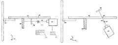
- FIG. 1illustrates a top view of an embodiment comprising an integration of a breast therapy system and multiple breast imaging systems.
- FIGS. 2 a - 2 dillustrate a top view of the therapy system of FIG. 1 in several different positions of a therapy radiation source.
- FIG. 3illustrates a top view of a patient table for use in the system of FIG. 1 .
- FIG. 4 aillustrates a side view of a patient table and a center of rotation of the radiation source about an upwardly extending axis.
- FIG. 4 billustrates a side view of a patient table and a center of rotation of the radiation source about a laterally extending axis.
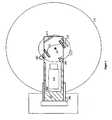
- FIG. 5 aillustrates a perspective view of the imaging/therapy system in relation to a desired isocenter of rotation.
- FIG. 5 billustrates a side view of the system.
- FIG. 6 ais a schematic illustration of an example of a radiation therapy and imaging system in side view
- FIG. 6 bis a schematic illustration of the system in a front view.
- FIG. 7is a schematic illustration of a system in side view that includes CT imaging provisions.
- FIG. 9illustrates range energy relationship for protons.
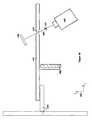
- a non-limiting example of the systemcomprises a table or couch 101 that is especially adapted to support a patient in the prone position but may also be used to support a patient in other positions such as in the supine position or another position.
- FIG. 1also illustrates one or more imaging systems discussed below in more detail for localizing and identifying a lesion or abnormality or target volume, a radiation source such as a special Linear Accelerator (LINAC) 105 for producing therapy radiation, and a motorized cantilevered stand 106 .
- LINACLinear Accelerator
- FIG. 1illustrates the table in FIG. 1 with a cutout 109 to allow visualizing the components that are below the table.
- the LINAC device 105is a compact version capable of producing penetrating radiation uniquely suited to breast-related tissue rather than optimized for whole-body radiation therapy.
- the imaging and therapy systemsmove about the patient's breast, preferably though not necessarily in rotation, and preferably the motion is centered on the lesion or target volume for therapy irradiation.
- the systemmay include provisions for moving the therapy and/or imaging components in a manner suitable for patients in other patient positions, such as the supine patient position.
- the imaging systems in FIG. 1 examplemay include: an x-ray system that uses an x-ray source 102 and x-ray digital imaging detector (flat panel) 120 , a stereotactic x-ray imaging system where two x-ray sources 102 and 103 are used with respective x-ray imaging panels 120 and 113 (or one set of a source such as 102 and a detector such as 120 is moved to one position for one x-ray image and another position for another image taken at a different angle relative to the patient's breast), PET or SPECT imaging panels or ultrasound transducers 104 , combinations of two or more of the imaging systems identified above, or other imaging systems If an x-ray imaging system is used, it can use only one, or both, of sources 102 and 103 and respective x-ray detector panels 113 and 120 , to image the patient's breast or other patient tissue.
- Imaging source 102 and x-ray panel 120are mounted to move about the breast as a unit, along path 112 , to image the breast from different angles. If source 103 and panel 113 are used, they also rotate or otherwise move as a unit, and if both source/panel sets are used, the two sets can rotate as a unit or individually. In each case, the motion can be about a center 107 that can be at the lesion or target volume or about some other center.
- the x-ray imaging system(s)may be used to derive projection tomosynthesis image data, for example by using motion and image reconstruction as disclosed in commonly assigned U.S. Pat. Nos.
- FIGS. 2 a - 2 dare top views of the system that illustrate examples of the range of positions of the therapy system in relation to patient table 101 (that again is shown with cutout 109 to allow seeing components below the table).
- a motorized stand 106supports table 101 for up-down motion and, if desirable, for motion along and across the length of the table, and also can support the imaging and therapy systems for rotation in a circle 111 representing a preferred 360 degree range of rotation of LINAC 105 and of the imaging system(s) around a selected center 107 . If portal imaging is used, a portal imaging detector 108 and the LINAC device 105 can move as a unit for imaging.
- FIG. 2 aillustrates the LINAC device at 0° relative to prone table 101 and isocenter 107 .
- Illustrative cutout 109reveals the LINAC source 105 , center 107 , and a radiation detector 108 .
- FIG. 2 billustrates LINAC source 105 at 180° relative to patient table 101 and center 107 .
- Illustrative cutout 109reveals center 107 and detector 108 .
- FIG. 2 cillustrates LINAC source 105 at approximately 45° relative to table 101 and center 108 .
- Illustrative cutout 109reveals center 108 and detector 108 .
- FIG. 2 dillustrates LINAC source 105 at 270° relative to prone table 101 and center 107 .
- Illustrative cutout 109reveals center 107 and detector 108 .
- circle 111representing the diameter and range of rotation of LINAC source 105 and imaging detector 108 preferably has a diameter of approximately three meters.
- Stand 106preferably extends approximately 1 meter from a wall. An range of rotation through an angle smaller than 360° can be used as an alternative.
- FIG. 3illustrates additional features of patient table 101 as seen in top plan view.
- Table 101comprises left and right removable mesh panels 303 , 304 that cover respective left and right openings in the table.
- a mesh panelWhen a mesh panel is removed from the table, the opening allows a patient's breast to extend downwardly for imaging and/or radiation therapy.
- the panelsare designed to be replaced by a breast stabilizing aide 101 A ( FIGS. 6 a and 6 b ), such as an aide made of an “Aquaplast” material or comparable material forming a semi-rigid thermoplastic surface around a breast.
- the system operating in an imaging mode with some or all of the associated modalitiescan be used to help establish the position and orientation of the stabilizing aide and to correlate what will become a semi-rigid surface of the thermoplastic material to the breast, the target volumes and the system reference frames.
- Additional or alternative stabilizing aidessuch as other thermoplastics, vacuum fixation, personal positioning cups, or variations of positioning boards and coaches may be employed in the radiotherapy apparatus disclosed herein.
- the stabilizing aide(s) or combinations thereofpreferably facilitate immobilizing a breast for imaging so that the target volume can be accurately and conveniently located in relation to patient and system geometry and the lesion or other radiation target volume can then be given a planned radiotherapy dosage.
- the use of stabilizing aides described herein and variations thereofcan assist the radiotherapy system in providing consistent and precise irradiation of a patient's anatomy on a daily or other basis.
- the stabilizing aides described hereinare relatively inexpensive and can be re-fabricated as needed during the course of therapy for clinical (anatomy changes, adema, etc) or patient comfort requirements.
- the table surfacecan be shaped, originally or with the help of special pillows, to provide patient comfort and to extend the appropriate anatomy as much as possible below the patient table.
- implantable or otherwise attachable position and/or dose sensors 107 afor use within or near a patient's breast or other anatomy can be utilized to further increase the accuracy and effectiveness of an individualized patient radiotherapy treatment plan, optionally in combination with one or more breast stabilizing aides.
- implantable position sensorscapable of communicating anatomical positioning information, an example of which is available from CALYPSO Medical od Seattle, Wash.
- One or more implantable position sensorscould be placed within a patients breast and surrounding anatomy and using wireless technology communicate with an embodiment of the radiotherapy system.
- implantable position sensors in communication with an embodiment of the radiotherapy system using one or more imaging modalitiescan accurately determine patient geometry in relation to the radiotherapy system geometry thereby allowing accurate and daily irradiation, or irradiation at a different schedule, of a patient concurrent with an individualized patient radiotherapy treatment plan.
- Implantable or otherwise attachable dose monitoring sensorssuch as those available from Sicel Technologies, Inc. of Morrisville, N.C. can be used within an embodiment of the disclosed radiotherapy system in addition to or optionally independent of implantable position monitors.
- Implantable monitoring sensorssuch as those from Sicel Technologies, Inc. can collect and store data related for example to tumor cell kinetics and physiology, pH or oxygen levels, temperature, uptake and retention of chemotherapeutic agents, as well as the radiation dose delivered to a region of a patient's anatomy. Said monitoring sensors then use wireless technology to communicate collected data to receivers located outside a patient's body.
- one or more implantable monitorscan be used in a non-limiting example as radiation dose monitors and can be implanted in a patient at or near the lesion to be treated with therapeutic radiation and optionally surrounding tissue as well.
- Implanted radiation dose monitorsare able to communicate to the radiotherapy system precisely what radiation dose is striking a patient's anatomy.
- Precise internal radiation dose information from implanted dose monitorscan accurately provide dose information to doctors, physicians, and embodiments of the radiotherapy system herein thereby limiting over- or under-irradiation of a patient's anatomy and aiding in accurate and consistent daily treatment according to a patient's radiotherapy treatment plan.
- FIG. 3further illustrates degrees of freedom of the motion of patient table 101 .
- the four directional arrows 302represent the direction of motions along which motorized stand 106 can move prone table 101 (in addition to any up-down or tilting motion).
- table 101can move approximately 10 centimeters in any direction from a resting position in the horizontal xy-plane parallel the floor. In a particular implementation, movement over distances greater or smaller than 10 cm can be selected.
- X and Y directionsare shown by axis 305 .
- Stand 106also can be configured to move the patient table in the vertical position, and/or to tilt table 101 , if desired.
- LINAC source 105is shown in FIG. 3 at a 180° position relative to table 101 .
- Arc 306is placed in FIG. 3 for illustrative purposes to exemplify a curved direction of motion of LINAC source 105 around table 101 , preferably about an isocenter of the system (not shown).
- the rotational movement of LINAC source 105can be combined with the vertical and horizontal movement of prone table 101 by motorized stand 106 allowing desired target volumes of a patient's breast and surrounding tissue to be imaged and receive appropriate doses of therapeutic radiation in accordance with an individual patient's radiation therapy plan.
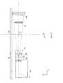
- FIG. 4 ais a side view of an example of the system, with LINAC source 105 at a 180° position around center 107 .
- a radiation beam centerline 403is shown of a shaped beam, e.g. a conical beam or a beam with a different cross-section and intensity distribution within the cross-section, exiting LINAC source 105 , passing through center 107 and impinging on imaging detector 108 .
- An additional featureis an optional beam blocker 608 that substantially stops primary photon energy that passes through imaging detector 108 .
- Table 101which is not shown to scale in terms of thickness, further comprises rounded openings 401 for a patient's breast, directly above center 107 .
- Z-Y directional axis 402is illustrated to show both the z-direction and y-direction of the system relative to the side view illustrated in FIG. 4 a .
- a motion control 610supports source 105 , imaging detector 108 , and beam blocker 608 and provides interface electrical and electronic connections between source 105 , detector 108 , and a sub-system 612 that serves as a system control and for processing and displaying data.
- Unit 610 and its connections to other unitsare shown schematically but it should be understood that the unit typically contains motors and associated components that impart the desired motions to source 105 , imaging detector 108 , and beam blocker 608 , including motion in the horizontal plane (flat or curved) about center 107 , tilting so that the motion about center 107 is in a plane (flat or curved) angled to the horizontal and such that at least source 105 can be at the level of or above patient table 101 , and translating motion that moves center 107 to the left or to the right or up or down as seen in FIG. 4 a .
- the schematic connections shown between unit 610 and source 105 and imaging detector 108represent both mechanical and electrical/electronic two-way communication.
- the two-directional arrows in the connections to units 105 , 108 , and 608schematically illustrate telescoping mechanism that can be motor-driven, e.g., by fluidic or electrical motors, up and down along the lengths of the mechanical supports.
- Unit 612need not be under table 101 ; in fact, typically it is not in the same room as the therapy/imaging system.
- the imaging systems illustrated in FIG. 1are not shown in FIG. 4 a but it should be understood that they can be mounted to and electrically/electronically connected to unit 610 in a manner in which their positions are known relative to the system frame of reference.
- source 105can be mounted and otherwise connected to a separate motion control and interface configured to move them in a way that does not interfere with the therapy radiation and portal imaging components.
- One of the motions of source 105 under patient table 101 about the patient's breasttypically is in a horizontal plane; however, provisions can be and preferable are made for deviations from a motion in a flat plane, such as for motion in which the vertical elevation of source 105 varies during its motion about the breast.
- source 105can move to positions at the level of, or above, patient table 101 . motion about the breast.
- FIG. 6 bdiscusses the source 105 can move to positions at the level of, or above, patient table 101 . motion about the breast.
- FIG. 4 bis similar to FIG. 4 a but illustrates an additional capability of a preferred embodiment of the disclosed radiotherapy system.
- units 610 and 612 and the mechanical and electrical/electronic connections of FIG. 4 aare not shown in FIG. 4 b but it should be understood that they are a part of the system as it would be seen in this configuration as well.
- lymphatic systems and anatomical tissuelocated outside of the breast tissue hanging pendulant through an opening or into a depression in table 101 .
- the disclosed imaging and therapy systemcan optionally tilt radiation source 105 such that a centerline of a therapy radiation it emits is at an angle to the horizontal, e.g. at 45°-55°.
- an emitted radiation beam centerline 403can pass upwards through a patient's armpit area and therapeutically irradiate lymphatic tissue and surrounding anatomical structures as desired.
- source 105is mounted for movement about center 107 about a non-vertical axis, in a non-horizontal plane that can be flat or curved, and one or both of source 105 and detector 108 can be mounted for movement toward and away from center 107 , along radiation centerline 403 , and thus toward or away from a target volume
- Radiation detector 108can be moved into a position above patient table 101 , to remain perpendicular to the radiation beam centerline 403 . In this case it is not necessary for the radiation beam centerline 403 to pass through an isocenter of the system.
- the precise pathway of the therapeutic radiation emitted from LINAC device 105is determined by the treatment plan for a particular patient.
- optional photon blocker 608also can be moved from below prone table 101 and positioned behind radiation detector 108 to absorb primary radiation still passing through detector 108 .
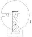
- FIG. 5 aillustrates a top view of a portion of the radiotherapy system comprising an abstract depiction of a preferred center 107 , a LINAC device 602 , additionally a solid state flat panel detector 607 , and an optional beam blocker 608 .
- the patient table normally located above the radiotherapy system as well as other components that are visible in other Figs.have been removed from the visual field so as to more easily illustrate features of a preferred embodiment of the radiotherapy system.
- the radiotherapy system of FIG. 5 acomprises a radiation beam centerline 601 , a compact LINAC 602 , a target assembly and carousel 603 , a primary dual independent collimator 604 , a tertiary multi leaf collimator 605 , a monitor chamber for beam streams 606 , a solid state panel detector 607 and optionally a beam blocker 608 .
- Also shown in FIG. 5 ais center 107 of the system, arrows 609 representing the direction of rotation of the LINAC in tandem with detector 607 and beam blocker 608 , and x-y system 501 indicating the x-direction and y-direction of the machine in this illustration.
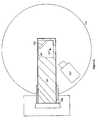
- FIG. 5 billustrates a side view of a preferred embodiment of a portion of the radiotherapy and imaging device used in the system shown in FIG. 5 a .
- the preferred embodimentcomprises a linear accelerator (LINAC) 602 , a target assembly and carousel 603 , a primary collimator 604 , a tertiary collimator 605 , a flat panel detector 607 , and an optional beam blocker 608 .
- LINAClinear accelerator
- the radiation source 602(which can but need not be a Linac source) in this embodiment preferably operates to produce one or more of the following four therapeutic forms of radiation: (i) direct electron (e ⁇ ) beams, (ii) direct proton (p+) beams, (iii) high energy Bremstrahlung photons from an accelerator source, and (iv) high energy photons from a radioisotope (Cobalt-60).
- source 602When high energy photons from a Bremstrahlung source are chosen as the therapeutic form of radiation then source 602 preferably operates to produce a stream of therapeutic photons having a maximum Bremstrahlung energy at or in the range 1 MeV to 10 MeV, preferably an average energy in the 4 MeV-6 MeV range, or in the 1 MeV-4 MeV range.
- a compact LINAC in the radiotherapy systemproduces a stream of therapeutic photons for irradiating breast tissue having an average energy in a specified range suitable for breast-related irradiation such as within the range of 1-2 MeV.
- a compact LINACcapable of producing therapeutic photons from a Bremstrahlung source wherein said photons have an average energy between 1-2 MeV, uses electrons with a peak energy preferably in the range of 1-6 MeV and more preferably within the energy range 4-6 MeV.
- LINAC manufacturerswould have attempted to reproduce the effective energy of Cobalt 60 decay photons (1.25 MeV) when making LINAC sources for treating breast tissue.
- Cobalt-60itself could also be used in the radiotherapy device claimed herein and the need for an accelerator removed.
- the LINACpreferably produces a stream of electrons, wherein the electrons have an energy range from 1-10 MeV, preferably in the range of 4-6 MeV
- the energy rangepreferably is selected according to criteria such as discussed in “The Physics of Radiation Therapy”, 3rd Edition, by Faiz Khan. Lippincott, Williams and Wilkins, ISBN 0-7817-3065-1, at pp. 56 & 57 (the “Book”).
- FIG. 8which is a reproduction of FIG. 4.16 in the Book, for such heavy particles the characteristic distribution of radiation dose with depth in the irradiated tissue is different from that for photons and electrons.
- the deposited doseis approximately constant with depth, or rises a little, until near the end of the depth range, where the dose peaks out to a high value followed by a rapid fall-off.
- the energy of other heavy charged particlessuch as deuterons, stripped carbon atoms, and others, can be expressed in MeV/u, where u is the mass number of the nucleus, so that particles that have about the same MeV/u would be expected to have about the same range in water or tissue. According to the Book, for water the rapid rise starts at about 12 cm penetration depth, and peaks at about 15-16 cm and then rapidly falls off. As seen in FIG. 9 , which is a reproduction of FIG.
- the proton energy rangeis approximately 80-180 MeV.
- the average energy of the heavy charged particles from a source such as 602exceeds 20 MeV, more preferably it exceeds 50 MeV, and most preferably it is in the range 80-180 MeV, in each case with a characteristic distribution with depth in breast tissue that has a Bragg peak followed by a rapid fall-off.
- an appropriate energycan be chosen to deposit the peak dose at the target volume of tissue. This can be particularly advantageous in the case of target volume that is at or close to the chest wall, because the rapid fall-off in dose after the peak leaves organs such as the lungs and heart with essentially zero dose.
- Another approachis to select heavy charged particles energy is to use energy corresponding to the average depth in the middle of the largest expected uncompressed breast.
- any of the forms of LINACs that are available from manufacturers such as Varianmay also be made more compact and thus the machine size smaller by the utilization of superconductive wave guide materials and associated technologies such as currently being used to generate superconducting cyclotrons for treating other deep-seated lesions such as prostate cancer.
- the radiation source 602produces a radiation beam centerline that ideally passes from the exit of the source straight through a center of the systems which is usually the lesion of the breast being treated or is some line through another volume that should be subjected to radiation therapy.
- the target assembly and carousel 603 included in the radiotherapy apparatusis used in an embodiment of the radiotherapy apparatus to switch the type of therapeutic radiation chosen for a particular volume in a patient's breast or surrounding tissue.
- the radiotherapy apparatuscan emit beta rays that are produced in a LINAC or comparable radiation source.
- the radiotherapy apparatuscan be configured for the production of photons such as gamma or x-rays.
- the primary collimator 604is followed by the tertiary or multi leaf collimator 605 that can produce in a non-limiting example a 3 mm leaf width at radiation and rotational center 107 of the system for precision treatment of voxels located within the breast.
- the radiotherapy apparatusadditionally can house a monitor chamber 606 positioned before the multi leaf collimator to assist in determining the amount of radiation being emitted from the radiation source and subsequently delivered to a particular volume in a patient.
- monitor chamber 606would remain in dynamic communication with a concurrent radiation monitoring system so that the radiotherapy system as accurately as possible provides therapeutic radiation in accordance with an individualized radiotherapy patient treatment plan.
- the radiationAfter passing through the center 107 , the radiation strikes a solid state flat panel detector 607 used for portal imaging.
- the flat panel detector 607is moveable relative to the beam of radiation so that it can be placed in the path of the beam for imaging and taken out of the path of the beam for radiation treatment.
- a beam blocker 608can be placed in the path of the beam to effectively stop radiation that has passed through the irradiated volume.
- optional beam blocker 608is placed within the path of the radiation emitted from source 602 illustrated by photon beam centerline 601 and positioned downstream of center 107 and flat panel detector 607 .
- the optional beam blocker 608can cut down the cost of shielding the room thereby reducing the structural footprint of a room housing this system, and making the system as a whole easier and less expensive to install and operate in hospitals, clinics, and other such facilities.
- FIGS. 6 a and 6 billustrate a variation of the system in which patient table 101 is supported on a motorized pedestal 650 that can selectively move table 101 along some or all the x, y, and z axes illustrated in FIGS. 6 a and 6 b , and also can tilt table 101 about some or all of these the axes.
- Another motorized pedestal 652supports a motorized plate 654 that in turn supports an arm 656 to which is mounted another arm 660 supporting therapy radiation source 105 , portal imaging detector 108 , and blocking plate 608 and any imaging system schematically illustrated at 658 .
- Pedestal 652selectively rotates plate 654 to move arm 656 and the components it carries between the positions shown in solid and in dotted lines, including any intermediate position.
- Motorized plate 654selectively moves arm 656 and the components attached to it up and down as illustrated by arrows in the z-direction and also telescopes or otherwise extends arm 656 and the components it carries in the y-direction as also illustrated by a bidirectional arrow.
- Arm 656also can be motorized to selectively rotate arm 660 about the z-axis at point 662 as illustrated by a bidirectional curved arrow.
- arm 660can be motorized to selectively rotate radiation source 105 about the x-axis at 664 as illustrated by another bidirectional curved arrow.
- FIG. 6 billustrates the same arrangement as FIG. 6 a but in a front elevation.
- the patientwould be prone on table 101 , with a breast extending downwardly through an opening or into a depression in table 101 , so that the breast and/or related tissue can be imaged and/or treated with radiation from below table 101 , through the motions referred to above patient tissue can also be treated with a radiation beam that extends from below table 101 through the patient at an angle to the horizontal, for example as illustrated in FIG. 4 b , or at any other suitable angle to the horizontal.
- the patientcan be in another position, such as the supine position, to be imaged and/or treated with radiation from a source position above table 101 , such as illustrated in dotted lines in FIGS. 6 a and 6 b.
- FIG. 7illustrates in side elevation an alternative that includes, in addition to the arrangement of FIGS. 6 a and 6 b , an arm 700 that is at the other side of patient table 101 and is mounted to plate 654 in a manner similar to that used for arm 656 .
- plate 654can be motorized to selectively move arm 700 up and down as seen in FIG. 7 and illustrated by arrows, and to extend or contract arm 700 in the y-direction as illustrated with a bidirectional arrow.
- Arm 700carries a specialized breast CT scanner 712 that is otherwise similar to commercially available CT scanners available from companies such as Giotto of Italy and distributed in this country primarily for imaging extremities by Hologic, Inc. of Bedford, Mass. but is smaller and lighter to serve as a dedicated breast CT scanner.
- the imaging functionalities of the disclosed system and methodcan be used to assist in brachytherapy; for example to verify the placement of radiation sources in the breast relative to breast anatomy, and to monitor the treatment.
- Some of the challenges of brachytherapyare to ensure that the distance along different directions between the radiation source inside the breast and the surrounding tissue conforms to the treatment plan, and that the tissue to be treated is the planned tissue.
- imagesmay be taken with a modality such as a CT scanner to confirm that the source is positioned well and to account to anatomy issues such as seromas, scar tissue, and hematomas. If a whole-body CT scanner is used, as is common, the imaging radiation traverses not only the breast that is being treated but also the other breast and the thorax.
- imaging and treatment planning facilities of the system and method described herewould involve imaging radiation dose delivered only to the breast being treated, and also would facilitate obtaining good images in the prone position, with the patient's breast extending down.
- brachytherapy instrumentscan be used, such as those offered by the assignee of this patent specification under the name Mammosite, by North American Scientific of Chatsworth, Calif., by Cianna Medical of California (formerly Biolucent), by SenoRx of Aliso Viejo, Calif., and other companies. Verification of brachytherapy treatment parameters using the imaging equipment described in this patent specification can be done before, during and/or after brachytherapy treatment and can involve placing the patient one or more times in the prone position on a patient table surface such as 101 . in FIG. 7 , with the patient's breast pendulously extending downwardly in an opening or depression in the table surface, and imaging the breast using any one or more of the modalities discussed in connection with FIG.
- brachytherapy planningincluding what brachytherapy device to use, in what way, what radiation agent to use and in what way, the treatment plan in terms of fractional and total dose, and other parameters related to brachytherapy treatment of the breast; (3) verifying and if needed adjusting the placement of brachytherapy devices in the breast or changing brachytherapy devices and/or internal radiation sources as desired, for example to ensure good contact between the device and breast tissue in the surgical cavity and to consider and account for anatomical features such as seromas and other anatomical irregularities; (4) assessing effects of brachytherapy treatment such as changes in breast tissue at or near the surgical cavity, and possibly modifying the treatment plan as a result of such assessment; and (5) post brachytherapy assessments.
- brachytherapy of a breastcan be combined with treatment radiation of the same breast or of related tissue in the same system, from an external source of radiation, while the patient is in the same position on the same patient table surface used for imaging, such as the system of FIG. 7 .
Landscapes
- Health & Medical Sciences (AREA)
- Engineering & Computer Science (AREA)
- Biomedical Technology (AREA)
- Life Sciences & Earth Sciences (AREA)
- Veterinary Medicine (AREA)
- Radiology & Medical Imaging (AREA)
- Nuclear Medicine, Radiotherapy & Molecular Imaging (AREA)
- Animal Behavior & Ethology (AREA)
- General Health & Medical Sciences (AREA)
- Public Health (AREA)
- Pathology (AREA)
- Medical Informatics (AREA)
- High Energy & Nuclear Physics (AREA)
- Biophysics (AREA)
- Physics & Mathematics (AREA)
- Optics & Photonics (AREA)
- Heart & Thoracic Surgery (AREA)
- Molecular Biology (AREA)
- Surgery (AREA)
- Dentistry (AREA)
- Oral & Maxillofacial Surgery (AREA)
- Radiation-Therapy Devices (AREA)
Abstract
Description
Claims (26)
Priority Applications (6)
| Application Number | Priority Date | Filing Date | Title |
|---|---|---|---|
| US11/903,859US20090080602A1 (en) | 2006-08-03 | 2007-09-24 | Dedicated breast radiation imaging/therapy system |
| US11/944,196US7957508B2 (en) | 2006-08-03 | 2007-11-21 | Dedicated breast radiation imaging/therapy system |
| EP08833561AEP2194877A4 (en) | 2007-09-24 | 2008-09-23 | Dedicated breast radiation imaging/therapy system |
| PCT/US2008/077381WO2009042597A1 (en) | 2006-08-03 | 2008-09-23 | Dedicated breast radiation imaging/therapy system |
| US13/109,460US8254521B2 (en) | 2007-08-03 | 2011-05-17 | Dedicated breast radiation imaging/therapy system |
| US13/558,146US8964936B2 (en) | 2006-08-03 | 2012-07-25 | Dedicated breast radiation imaging/therapy system |
Applications Claiming Priority (3)
| Application Number | Priority Date | Filing Date | Title |
|---|---|---|---|
| US83580306P | 2006-08-03 | 2006-08-03 | |
| US11/903,859US20090080602A1 (en) | 2006-08-03 | 2007-09-24 | Dedicated breast radiation imaging/therapy system |
| US11/944,196US7957508B2 (en) | 2006-08-03 | 2007-11-21 | Dedicated breast radiation imaging/therapy system |
Related Parent Applications (1)
| Application Number | Title | Priority Date | Filing Date |
|---|---|---|---|
| US11/903,859Continuation-In-PartUS20090080602A1 (en) | 2006-08-03 | 2007-09-24 | Dedicated breast radiation imaging/therapy system |
Related Child Applications (1)
| Application Number | Title | Priority Date | Filing Date |
|---|---|---|---|
| US13/109,460DivisionUS8254521B2 (en) | 2006-08-03 | 2011-05-17 | Dedicated breast radiation imaging/therapy system |
Publications (2)
| Publication Number | Publication Date |
|---|---|
| US20090080594A1 US20090080594A1 (en) | 2009-03-26 |
| US7957508B2true US7957508B2 (en) | 2011-06-07 |
Family
ID=44661296
Family Applications (4)
| Application Number | Title | Priority Date | Filing Date |
|---|---|---|---|
| US11/903,859AbandonedUS20090080602A1 (en) | 2006-08-03 | 2007-09-24 | Dedicated breast radiation imaging/therapy system |
| US11/944,196Active2028-03-09US7957508B2 (en) | 2006-08-03 | 2007-11-21 | Dedicated breast radiation imaging/therapy system |
| US13/109,460ActiveUS8254521B2 (en) | 2006-08-03 | 2011-05-17 | Dedicated breast radiation imaging/therapy system |
| US13/558,146ActiveUS8964936B2 (en) | 2006-08-03 | 2012-07-25 | Dedicated breast radiation imaging/therapy system |
Family Applications Before (1)
| Application Number | Title | Priority Date | Filing Date |
|---|---|---|---|
| US11/903,859AbandonedUS20090080602A1 (en) | 2006-08-03 | 2007-09-24 | Dedicated breast radiation imaging/therapy system |
Family Applications After (2)
| Application Number | Title | Priority Date | Filing Date |
|---|---|---|---|
| US13/109,460ActiveUS8254521B2 (en) | 2006-08-03 | 2011-05-17 | Dedicated breast radiation imaging/therapy system |
| US13/558,146ActiveUS8964936B2 (en) | 2006-08-03 | 2012-07-25 | Dedicated breast radiation imaging/therapy system |
Country Status (3)
| Country | Link |
|---|---|
| US (4) | US20090080602A1 (en) |
| EP (1) | EP2194877A4 (en) |
| WO (1) | WO2009042597A1 (en) |
Cited By (14)
| Publication number | Priority date | Publication date | Assignee | Title |
|---|---|---|---|---|
| US20110200178A1 (en)* | 2010-02-18 | 2011-08-18 | Varian Medical Systems, Inc. | Prone patient positioning devices and methods |
| US20150257726A1 (en)* | 2014-03-12 | 2015-09-17 | Canon Kabushiki Kaisha | Breast tomography apparatus and control method |
| US20170332988A1 (en)* | 2015-06-30 | 2017-11-23 | Canon Kabushiki Kaisha | Breast imaging apparatus |
| US20180008221A1 (en)* | 2014-12-09 | 2018-01-11 | Canon Kabushiki Kaisha | Breast computed tomography system |
| US9950194B2 (en) | 2014-09-09 | 2018-04-24 | Mevion Medical Systems, Inc. | Patient positioning system |
| US9962560B2 (en) | 2013-12-20 | 2018-05-08 | Mevion Medical Systems, Inc. | Collimator and energy degrader |
| US10646728B2 (en) | 2015-11-10 | 2020-05-12 | Mevion Medical Systems, Inc. | Adaptive aperture |
| US10653892B2 (en) | 2017-06-30 | 2020-05-19 | Mevion Medical Systems, Inc. | Configurable collimator controlled using linear motors |
| US10675487B2 (en) | 2013-12-20 | 2020-06-09 | Mevion Medical Systems, Inc. | Energy degrader enabling high-speed energy switching |
| US10925147B2 (en) | 2016-07-08 | 2021-02-16 | Mevion Medical Systems, Inc. | Treatment planning |
| US11103730B2 (en) | 2017-02-23 | 2021-08-31 | Mevion Medical Systems, Inc. | Automated treatment in particle therapy |
| US20230022716A1 (en)* | 2021-07-20 | 2023-01-26 | Mevion Medical Systems, Inc. | Gantry having a retractable cover |
| US20230101051A1 (en)* | 2021-09-29 | 2023-03-30 | Hitachi, Ltd. | Radiation treatment system and method of operating radiation treatment system |
| US12245355B2 (en) | 2021-02-19 | 2025-03-04 | Mevion Medical Systems, Inc. | Gantry for a particle therapy system |
Families Citing this family (87)
| Publication number | Priority date | Publication date | Assignee | Title |
|---|---|---|---|---|
| US8565372B2 (en) | 2003-11-26 | 2013-10-22 | Hologic, Inc | System and method for low dose tomosynthesis |
| US8571289B2 (en) | 2002-11-27 | 2013-10-29 | Hologic, Inc. | System and method for generating a 2D image from a tomosynthesis data set |
| US7616801B2 (en) | 2002-11-27 | 2009-11-10 | Hologic, Inc. | Image handling and display in x-ray mammography and tomosynthesis |
| US7577282B2 (en) | 2002-11-27 | 2009-08-18 | Hologic, Inc. | Image handling and display in X-ray mammography and tomosynthesis |
| US7123684B2 (en)* | 2002-11-27 | 2006-10-17 | Hologic, Inc. | Full field mammography with tissue exposure control, tomosynthesis, and dynamic field of view processing |
| US10638994B2 (en) | 2002-11-27 | 2020-05-05 | Hologic, Inc. | X-ray mammography with tomosynthesis |
| US7662082B2 (en) | 2004-11-05 | 2010-02-16 | Theragenics Corporation | Expandable brachytherapy device |
| US7702142B2 (en) | 2004-11-15 | 2010-04-20 | Hologic, Inc. | Matching geometry generation and display of mammograms and tomosynthesis images |
| EP1816965B1 (en) | 2004-11-26 | 2016-06-29 | Hologic, Inc. | Integrated multi-mode mammography/tomosynthesis x-ray system |
| US7465268B2 (en) | 2005-11-18 | 2008-12-16 | Senorx, Inc. | Methods for asymmetrical irradiation of a body cavity |
| WO2007095330A2 (en) | 2006-02-15 | 2007-08-23 | Hologic Inc | Breast biopsy and needle localization using tomosynthesis systems |
| US7630533B2 (en) | 2007-09-20 | 2009-12-08 | Hologic, Inc. | Breast tomosynthesis with display of highlighted suspected calcifications |
| JP2010075338A (en)* | 2008-09-25 | 2010-04-08 | Fujifilm Corp | Mammography and therapy apparatus equipped with x-ray therapy function |
| US9579524B2 (en) | 2009-02-11 | 2017-02-28 | Hologic, Inc. | Flexible multi-lumen brachytherapy device |
| US9248311B2 (en) | 2009-02-11 | 2016-02-02 | Hologic, Inc. | System and method for modifying a flexibility of a brachythereapy catheter |
| US10207126B2 (en) | 2009-05-11 | 2019-02-19 | Cytyc Corporation | Lumen visualization and identification system for multi-lumen balloon catheter |
| US8218723B2 (en)* | 2009-07-12 | 2012-07-10 | Moshe Ein-Gal | Support system for breast irradiation |
| EP2277592A1 (en)* | 2009-07-23 | 2011-01-26 | Siemens Schweiz AG | Method and device for simulating radiation of an event to be controlled of an irradiator to be aligned on a target volume |
| ES2862525T3 (en) | 2009-10-08 | 2021-10-07 | Hologic Inc | Needle Breast Biopsy System and Method of Use |
| US8559590B2 (en)* | 2010-01-28 | 2013-10-15 | Varian Medical Systems, Inc. | Imaging breast cancerous lesions with microcalcifications |
| US9687200B2 (en) | 2010-06-08 | 2017-06-27 | Accuray Incorporated | Radiation treatment delivery system with translatable ring gantry |
| US8934605B2 (en) | 2010-02-24 | 2015-01-13 | Accuray Incorporated | Gantry image guided radiotherapy system and related treatment delivery methods |
| JP5815218B2 (en)* | 2010-08-30 | 2015-11-17 | 株式会社東芝 | Radiotherapy apparatus, control method, and control program |
| US9352172B2 (en) | 2010-09-30 | 2016-05-31 | Hologic, Inc. | Using a guide member to facilitate brachytherapy device swap |
| WO2012045040A1 (en)* | 2010-10-01 | 2012-04-05 | Varian Medical Systems, Inc. | Laser accelerator driven particle brachytherapy devices, systems, and methods |
| CA2813591C (en) | 2010-10-05 | 2020-09-22 | Hologic, Inc. | Upright x-ray breast imaging with a ct mode, multiple tomosynthesis modes, and a mammography mode |
| US20120133600A1 (en) | 2010-11-26 | 2012-05-31 | Hologic, Inc. | User interface for medical image review workstation |
| US10342992B2 (en) | 2011-01-06 | 2019-07-09 | Hologic, Inc. | Orienting a brachytherapy applicator |
| US8536547B2 (en) | 2011-01-20 | 2013-09-17 | Accuray Incorporated | Ring gantry radiation treatment delivery system with dynamically controllable inward extension of treatment head |
| JP6057922B2 (en) | 2011-03-08 | 2017-01-11 | ホロジック, インコーポレイテッドHologic, Inc. | System and method for dual energy and / or contrast enhanced breast imaging for screening, diagnosis and biopsy |
| US9789337B2 (en)* | 2011-10-07 | 2017-10-17 | Siemens Medical Solutions Usa, Inc. | Combined imaging modalities for radiation treatment planning |
| EP2782505B1 (en) | 2011-11-27 | 2020-04-22 | Hologic, Inc. | System and method for generating a 2d image using mammography and/or tomosynthesis image data |
| JP6240097B2 (en) | 2012-02-13 | 2017-11-29 | ホロジック インコーポレイティッド | How to navigate a tomosynthesis stack using composite image data |
| US20130235969A1 (en)* | 2012-03-01 | 2013-09-12 | Imris Inc. | Patient Alignment in MRI Guided Radiation Therapy |
| EP2687159B1 (en)* | 2012-07-20 | 2016-06-29 | Deutschmann, Heinrich | Patient positioning and imaging system |
| WO2014111869A2 (en)* | 2013-01-17 | 2014-07-24 | Panacea Medical Technologies Pvt. Ltd | An apparatus to deliver conformal radiotherapy using external beam cobalt 60 |
| WO2014138500A1 (en)* | 2013-03-08 | 2014-09-12 | University Of Massachusetts Medical School | Apparatus and method for x-ray-based breast imaging |
| US10092358B2 (en) | 2013-03-15 | 2018-10-09 | Hologic, Inc. | Tomosynthesis-guided biopsy apparatus and method |
| CN105451657A (en) | 2013-03-15 | 2016-03-30 | 霍罗吉克公司 | System and method for navigating tomosynthesis stack including automatic focusing |
| CA2925907C (en) | 2013-10-09 | 2022-03-15 | Hologic, Inc. | X-ray breast tomosynthesis enhancing spatial resolution including in the thickness direction of a flattened breast |
| EP3060132B1 (en) | 2013-10-24 | 2019-12-04 | Hologic, Inc. | System and method for navigating x-ray guided breast biopsy |
| CN104936653B (en)* | 2013-11-01 | 2018-01-23 | 西安大医数码技术有限公司 | A multi-purpose radiotherapy system |
| JP6506769B2 (en) | 2014-02-28 | 2019-04-24 | ホロジック, インコーポレイテッドHologic, Inc. | System and method for generating and displaying tomosynthesis image slabs |
| US10548542B2 (en)* | 2014-03-24 | 2020-02-04 | Universiteit Gent | Radiotherapy board and couch |
| US9694210B2 (en)* | 2015-04-21 | 2017-07-04 | Cybermed Technologies (Xi'an) Co., Ltd. | Multi-purpose radiation therapy system |
| EP3413802B1 (en)* | 2016-02-09 | 2024-07-10 | Delphinus Medical Technologies, Inc. | System for shaping and positioning a tissue body |
| WO2017142747A1 (en) | 2016-02-16 | 2017-08-24 | Zhang Jiaju | Prone breast board for high-dose-rate partial breast irradiation brachytherapy |
| WO2017185028A1 (en) | 2016-04-22 | 2017-10-26 | Hologic, Inc. | Tomosynthesis with shifting focal spot x-ray system using an addressable array |
| WO2018031365A1 (en)* | 2016-08-09 | 2018-02-15 | University Of Maryland, Baltimore | System and method for optimizing a treatment plan for irradiation therapy |
| US12128252B2 (en)* | 2017-01-06 | 2024-10-29 | Accuray Incorporated | No-view interfraction treatment target motion management using volumetric imaging |
| CN110621233B (en) | 2017-03-30 | 2023-12-12 | 豪洛捷公司 | Method for processing breast tissue image data |
| EP3600052A1 (en) | 2017-03-30 | 2020-02-05 | Hologic, Inc. | System and method for targeted object enhancement to generate synthetic breast tissue images |
| EP3600047A1 (en) | 2017-03-30 | 2020-02-05 | Hologic, Inc. | System and method for hierarchical multi-level feature image synthesis and representation |
| WO2018236565A1 (en) | 2017-06-20 | 2018-12-27 | Hologic, Inc. | METHOD AND SYSTEM FOR MEDICAL IMAGING WITH DYNAMIC SELF-LEARNING |
| EP4129188A1 (en) | 2017-08-16 | 2023-02-08 | Hologic, Inc. | Techniques for breast imaging patient motion artifact compensation |
| EP3449835B1 (en) | 2017-08-22 | 2023-01-11 | Hologic, Inc. | Computed tomography system and method for imaging multiple anatomical targets |
| US10893844B1 (en)* | 2018-10-10 | 2021-01-19 | David Byron Douglas | Method and apparatus for performing 3D imaging examinations of a structure under differing configurations and analyzing morphologic changes |
| EP3787520B1 (en) | 2018-05-04 | 2024-09-25 | Hologic, Inc. | Biopsy needle visualization |
| US12121304B2 (en) | 2018-05-04 | 2024-10-22 | Hologic, Inc. | Introducer and localization wire visualization |
| KR102068326B1 (en)* | 2018-06-27 | 2020-01-20 | 한국원자력의학원 | Radiation therapy apparatus for animals |
| US11090017B2 (en) | 2018-09-13 | 2021-08-17 | Hologic, Inc. | Generating synthesized projection images for 3D breast tomosynthesis or multi-mode x-ray breast imaging |
| US11000241B2 (en)* | 2018-09-21 | 2021-05-11 | Hologic, Inc. | Breast securement devices and methods of securing breasts for imaging |
| WO2020068851A1 (en) | 2018-09-24 | 2020-04-02 | Hologic, Inc. | Breast mapping and abnormality localization |
| WO2020068767A1 (en) | 2018-09-28 | 2020-04-02 | Hologic, Inc. | System and method for synthetic breast tissue image generation by high density element suppression |
| WO2020107019A1 (en) | 2018-11-25 | 2020-05-28 | Hologic, Inc. | Multimodality hanging protocols |
| JP7294592B2 (en)* | 2018-12-03 | 2023-06-20 | ザ ユニバーシティ オブ ノース カロライナ アット チャペル ヒル | Compact X-ray device, system and method for tomosynthesis, fluoroscopy and stereotactic imaging |
| EP3669940B1 (en)* | 2018-12-20 | 2024-05-01 | RaySearch Laboratories AB | System and method for passive ion radiotherapy treatment planning and delivery |
| US10926111B2 (en)* | 2019-03-21 | 2021-02-23 | Vieworks Co., Ltd. | Bragg peak detector using scintillators and method of operating the same |
| DE202020006044U1 (en) | 2019-03-29 | 2024-07-02 | Hologic Inc. | Report generation for cropped digital images |
| US11883206B2 (en) | 2019-07-29 | 2024-01-30 | Hologic, Inc. | Personalized breast imaging system |
| EP4439580A3 (en) | 2019-09-27 | 2024-12-25 | Hologic, Inc. | Ai system for predicting reading time and reading complexity for reviewing 2d/3d breast images |
| EP3832689A3 (en) | 2019-12-05 | 2021-08-11 | Hologic, Inc. | Systems and methods for improved x-ray tube life |
| US11481038B2 (en) | 2020-03-27 | 2022-10-25 | Hologic, Inc. | Gesture recognition in controlling medical hardware or software |
| US11471118B2 (en) | 2020-03-27 | 2022-10-18 | Hologic, Inc. | System and method for tracking x-ray tube focal spot position |
| KR102724591B1 (en)* | 2020-05-29 | 2024-10-30 | (의료)길의료재단 | Radiation Therapy Device for Breast Cancer |
| KR102724593B1 (en)* | 2020-05-29 | 2024-10-30 | (의료)길의료재단 | Control Method for Radiation Device |
| KR102724592B1 (en)* | 2020-05-29 | 2024-10-30 | (의료)길의료재단 | Radiation Therapy Device for Breast Cancer |
| KR102640269B1 (en)* | 2020-05-29 | 2024-02-26 | (의료)길의료재단 | Radiation Therapy Device for Breast Cancer |
| KR102789254B1 (en)* | 2020-05-29 | 2025-04-01 | (의료)길의료재단 | Control Method for Radiation Device |
| US11692851B2 (en)* | 2020-10-16 | 2023-07-04 | Varian Medical Systems, Inc. | Magnetoresistive rotational position detection in a radiation therapy system |
| US11344749B2 (en) | 2020-10-16 | 2022-05-31 | Varian Medical Systems, Inc. | Magnetoresistive linear position detection in a radiation therapy system |
| JP2024506842A (en)* | 2021-02-01 | 2024-02-15 | ザップ サージカル システムズ, インコーポレイテッド | Reverse planning device and method for radiotherapy |
| US11786191B2 (en) | 2021-05-17 | 2023-10-17 | Hologic, Inc. | Contrast-enhanced tomosynthesis with a copper filter |
| US12186119B2 (en) | 2021-10-05 | 2025-01-07 | Hologic, Inc. | Interactive model interface for image selection in medical imaging systems |
| US12254586B2 (en) | 2021-10-25 | 2025-03-18 | Hologic, Inc. | Auto-focus tool for multimodality image review |
| WO2023097279A1 (en) | 2021-11-29 | 2023-06-01 | Hologic, Inc. | Systems and methods for correlating objects of interest |
| US12414217B2 (en) | 2022-02-07 | 2025-09-09 | Hologic, Inc. | Systems and methods for adaptively controlling filament current in an X-ray tube |
Citations (61)
| Publication number | Priority date | Publication date | Assignee | Title |
|---|---|---|---|---|
| US3165630A (en) | 1961-06-13 | 1965-01-12 | Polaroid Corp | Table for holding and positioning a female subject and film during breast x-ray exposures |
| US3556081A (en) | 1968-05-20 | 1971-01-19 | Holotron Corp | Breast holder for mammograph |
| US3578971A (en) | 1968-11-21 | 1971-05-18 | Harold J Lasky | Mammographic x-ray apparatus and technique |
| US3852610A (en) | 1973-02-26 | 1974-12-03 | Varian Associates | Transmission ion chamber |
| US3963933A (en) | 1975-08-18 | 1976-06-15 | General Electric Company | Mammography fixture |
| US3973126A (en) | 1975-07-31 | 1976-08-03 | General Electric Company | Mammography |
| US4015836A (en) | 1975-07-31 | 1977-04-05 | General Electric Company | Mammography table |
| US4051380A (en) | 1976-03-31 | 1977-09-27 | Lasky Harold J | Apparatus and method for supporting and positioning the body to facilitate radiographic mammography procedures |
| GB2068700A (en) | 1980-01-26 | 1981-08-12 | Emi Ltd | Positioning devices for patients |
| US4726046A (en) | 1985-11-05 | 1988-02-16 | Varian Associates, Inc. | X-ray and electron radiotherapy clinical treatment machine |
| US4868843A (en) | 1986-09-10 | 1989-09-19 | Varian Associates, Inc. | Multileaf collimator and compensator for radiotherapy machines |
| US4988919A (en) | 1985-05-13 | 1991-01-29 | Varian Associates, Inc. | Small-diameter standing-wave linear accelerator structure |
| US4998268A (en) | 1989-02-09 | 1991-03-05 | James Winter | Apparatus and method for therapeutically irradiating a chosen area using a diagnostic computer tomography scanner |
| US5008907A (en) | 1989-05-31 | 1991-04-16 | The Regents Of The University Of California | Therapy x-ray scanner |
| US5078142A (en) | 1989-11-21 | 1992-01-07 | Fischer Imaging Corporation | Precision mammographic needle biopsy system |
| US5422926A (en) | 1990-09-05 | 1995-06-06 | Photoelectron Corporation | X-ray source with shaped radiation pattern |
| US5426685A (en) | 1991-11-27 | 1995-06-20 | Thermotrex Corporation | Stereotactic mammography system imaging |
| US5548627A (en) | 1992-03-19 | 1996-08-20 | Wisconsin Alumni Research Foundation | Radiation therapy system with constrained rotational freedom |
| US5564438A (en) | 1993-08-09 | 1996-10-15 | Merchant; Thomas E. | Method and apparatus for prone position radiation therapy of the breast |
| US5574763A (en) | 1994-02-21 | 1996-11-12 | Siemens Aktiengesellschaft | Computed tomography apparatus |
| US5583908A (en) | 1993-04-30 | 1996-12-10 | Board Of Regents, The University Of Texas System | Megavoltage scanning imager and method for its use |
| US5622187A (en) | 1994-09-30 | 1997-04-22 | Nomos Corporation | Method and apparatus for patient positioning for radiation therapy |
| US5682890A (en) | 1995-01-26 | 1997-11-04 | Picker International, Inc. | Magnetic resonance stereotactic surgery with exoskeleton tissue stabilization |
| US5803912A (en) | 1989-11-21 | 1998-09-08 | Fischer Imaging Corporation | Positioning function mammographic biopsy function system with offset |
| US5803913A (en) | 1994-06-03 | 1998-09-08 | Khalkhali; Iraj | Nuclear medicine stereotaxic localization apparatus for breast carcinomas and method |
| US5851182A (en) | 1996-09-11 | 1998-12-22 | Sahadevan; Velayudhan | Megavoltage radiation therapy machine combined to diagnostic imaging devices for cost efficient conventional and 3D conformal radiation therapy with on-line Isodose port and diagnostic radiology |
| US6179766B1 (en) | 1999-01-28 | 2001-01-30 | Gregg A. Dickerson | Methods of breast cancer treatment |
| US6279579B1 (en) | 1998-10-23 | 2001-08-28 | Varian Medical Systems, Inc. | Method and system for positioning patients for medical treatment procedures |
| US6298114B1 (en) | 1994-05-11 | 2001-10-02 | Mitsubishi Denki Kabushiki Kaisha | X-ray mammography apparatus |
| US6405072B1 (en) | 1991-01-28 | 2002-06-11 | Sherwood Services Ag | Apparatus and method for determining a location of an anatomical target with reference to a medical apparatus |
| US20020143249A1 (en) | 2001-03-30 | 2002-10-03 | Duke University. | Application specific emission and transmission tomography |
| US6463122B1 (en) | 2000-08-21 | 2002-10-08 | Bio-Imaging Resource, Inc. | Mammography of computer tomography for imaging and therapy |
| US6480565B1 (en)* | 1999-11-18 | 2002-11-12 | University Of Rochester | Apparatus and method for cone beam volume computed tomography breast imaging |
| US20030073895A1 (en) | 1996-10-15 | 2003-04-17 | Nields Morgan W. | User interface system for mammographic imager |
| US6661870B2 (en) | 2001-03-09 | 2003-12-09 | Tomotherapy Incorporated | Fluence adjustment for improving delivery to voxels without reoptimization |
| US6748044B2 (en)* | 2002-09-13 | 2004-06-08 | Ge Medical Systems Global Technology Company, Llc | Computer assisted analysis of tomographic mammography data |
| US20040171933A1 (en) | 2002-11-25 | 2004-09-02 | Milton Stoller | Mammography needle biopsy system and method |
| US6883194B2 (en) | 2002-11-08 | 2005-04-26 | Art Advanced Research And Technology Inc. | Method and apparatus for positioning a patient on a table for a medical procedure on a breast |
| US6987831B2 (en)* | 1999-11-18 | 2006-01-17 | University Of Rochester | Apparatus and method for cone beam volume computed tomography breast imaging |
| US7016522B2 (en) | 2002-01-15 | 2006-03-21 | Siemens Medical Solutions Usa, Inc. | Patient positioning by video imaging |
| US7046831B2 (en) | 2001-03-09 | 2006-05-16 | Tomotherapy Incorporated | System and method for fusion-aligned reprojection of incomplete data |
| US7122803B2 (en) | 2005-02-16 | 2006-10-17 | Hologic, Inc. | Amorphous selenium flat panel x-ray imager for tomosynthesis and static imaging |
| US7123684B2 (en) | 2002-11-27 | 2006-10-17 | Hologic, Inc. | Full field mammography with tissue exposure control, tomosynthesis, and dynamic field of view processing |
| US20060239398A1 (en) | 2005-03-07 | 2006-10-26 | Fused Multimodality Imaging, Ltd. | Breast diagnostic apparatus for fused SPECT, PET, x-ray CT, and optical surface imaging of breast cancer |
| US20060262898A1 (en) | 2005-05-20 | 2006-11-23 | Varian Medical Systems, Inc. | System and method for imaging and treatment of tumorous tissue in breasts using computed tomography and radiotherapy |
| US7154991B2 (en) | 2003-10-17 | 2006-12-26 | Accuray, Inc. | Patient positioning assembly for therapeutic radiation system |
| US20060293644A1 (en) | 2005-06-21 | 2006-12-28 | Donald Umstadter | System and methods for laser-generated ionizing radiation |
| US20070033735A1 (en) | 2005-04-06 | 2007-02-15 | New York University | Radiation treatment table and method for prone breast radiation treatment |
| US7199382B2 (en) | 2003-08-12 | 2007-04-03 | Loma Linda University Medical Center | Patient alignment system with external measurement and object coordination for radiation therapy system |
| US7233005B2 (en) | 2005-02-16 | 2007-06-19 | Hologic, Inc. | Amorphous selenium flat panel x-ray imager for tomosynthesis and static imaging |
| US7239684B2 (en) | 2005-02-28 | 2007-07-03 | Mitsubishi Heavy Industries, Ltd. | Radiotherapy apparatus monitoring therapeutic field in real-time during treatment |
| US7245694B2 (en) | 2005-08-15 | 2007-07-17 | Hologic, Inc. | X-ray mammography/tomosynthesis of patient's breast |
| US20070167664A1 (en) | 2005-10-31 | 2007-07-19 | Hermann George D | Brachytherapy apparatus and methods of using same |
| US20070269000A1 (en) | 2006-05-18 | 2007-11-22 | Partain Larry D | Contrast-enhanced cone beam X-ray imaging, evaluation, monitoring and treatment delivery |
| US7402822B2 (en)* | 2006-06-05 | 2008-07-22 | Varian Medical Systems Technologies, Inc. | Particle beam nozzle transport system |
| US7450688B2 (en)* | 2005-07-22 | 2008-11-11 | Wisconsin Alumni Research Foundation | Low skin dose patient positioning device for radiation treatment of prone breast |
| US7519149B2 (en)* | 2005-04-01 | 2009-04-14 | Wisconsin Alumni Research Foundation | Small field intensity modulated radiation therapy machine |
| US7526066B2 (en)* | 2006-03-07 | 2009-04-28 | Orbital Therapy, Llc | Radiation therapy system for treating breasts and extremities |
| US7561661B2 (en)* | 2006-10-31 | 2009-07-14 | Xcounter Ab | Imaging arrangement and system for imaging |
| US7649981B2 (en)* | 2003-10-15 | 2010-01-19 | Varian Medical Systems, Inc. | Multi-energy x-ray source |
| US7668287B2 (en)* | 2008-03-17 | 2010-02-23 | Fujifilm Corporation | Radiation CT apparatus |
Family Cites Families (8)
| Publication number | Priority date | Publication date | Assignee | Title |
|---|---|---|---|---|
| US6985557B2 (en)* | 2002-03-20 | 2006-01-10 | Minnesota Medical Physics Llc | X-ray apparatus with field emission current stabilization and method of providing x-ray radiation therapy |
| US7322929B2 (en)* | 2003-06-18 | 2008-01-29 | Xoft, Inc. | Method for radiation treatment |
| US7513861B2 (en)* | 2003-06-18 | 2009-04-07 | Xoft, Inc. | Real time verification in radiation treatment |
| JP4073876B2 (en)* | 2004-01-14 | 2008-04-09 | 三菱電機株式会社 | Semiconductor device |
| US7699783B2 (en)* | 2004-04-08 | 2010-04-20 | Techniscan, Inc. | Method for imaging and treating a breast |
| US20080043905A1 (en)* | 2006-08-21 | 2008-02-21 | Bamdad Hassanpourgol | Portable Prone Stereotactic Mammography System for Biopsies, Image Guided Lumpectomies, and Radiation Treatment |
| JP4857070B2 (en)* | 2006-10-11 | 2012-01-18 | キヤノン株式会社 | Mammography X-ray CT system |
| WO2009026587A1 (en)* | 2007-08-23 | 2009-02-26 | Fischer Medical Technologies, Inc. | Improved computed tomography breast imaging and biopsy system |
- 2007
- 2007-09-24USUS11/903,859patent/US20090080602A1/ennot_activeAbandoned
- 2007-11-21USUS11/944,196patent/US7957508B2/enactiveActive
- 2008
- 2008-09-23EPEP08833561Apatent/EP2194877A4/ennot_activeWithdrawn
- 2008-09-23WOPCT/US2008/077381patent/WO2009042597A1/enactiveApplication Filing
- 2011
- 2011-05-17USUS13/109,460patent/US8254521B2/enactiveActive
- 2012
- 2012-07-25USUS13/558,146patent/US8964936B2/enactiveActive
Patent Citations (65)
| Publication number | Priority date | Publication date | Assignee | Title |
|---|---|---|---|---|
| US3165630A (en) | 1961-06-13 | 1965-01-12 | Polaroid Corp | Table for holding and positioning a female subject and film during breast x-ray exposures |
| US3556081A (en) | 1968-05-20 | 1971-01-19 | Holotron Corp | Breast holder for mammograph |
| US3578971A (en) | 1968-11-21 | 1971-05-18 | Harold J Lasky | Mammographic x-ray apparatus and technique |
| US3852610A (en) | 1973-02-26 | 1974-12-03 | Varian Associates | Transmission ion chamber |
| US3973126A (en) | 1975-07-31 | 1976-08-03 | General Electric Company | Mammography |
| US4015836A (en) | 1975-07-31 | 1977-04-05 | General Electric Company | Mammography table |
| US3963933A (en) | 1975-08-18 | 1976-06-15 | General Electric Company | Mammography fixture |
| US4051380A (en) | 1976-03-31 | 1977-09-27 | Lasky Harold J | Apparatus and method for supporting and positioning the body to facilitate radiographic mammography procedures |
| GB2068700A (en) | 1980-01-26 | 1981-08-12 | Emi Ltd | Positioning devices for patients |
| US4988919A (en) | 1985-05-13 | 1991-01-29 | Varian Associates, Inc. | Small-diameter standing-wave linear accelerator structure |
| US4726046A (en) | 1985-11-05 | 1988-02-16 | Varian Associates, Inc. | X-ray and electron radiotherapy clinical treatment machine |
| US4868843A (en) | 1986-09-10 | 1989-09-19 | Varian Associates, Inc. | Multileaf collimator and compensator for radiotherapy machines |
| US4998268A (en) | 1989-02-09 | 1991-03-05 | James Winter | Apparatus and method for therapeutically irradiating a chosen area using a diagnostic computer tomography scanner |
| US5008907A (en) | 1989-05-31 | 1991-04-16 | The Regents Of The University Of California | Therapy x-ray scanner |
| US5078142A (en) | 1989-11-21 | 1992-01-07 | Fischer Imaging Corporation | Precision mammographic needle biopsy system |
| US5803912A (en) | 1989-11-21 | 1998-09-08 | Fischer Imaging Corporation | Positioning function mammographic biopsy function system with offset |
| US5422926A (en) | 1990-09-05 | 1995-06-06 | Photoelectron Corporation | X-ray source with shaped radiation pattern |
| US6662036B2 (en) | 1991-01-28 | 2003-12-09 | Sherwood Services Ag | Surgical positioning system |
| US6405072B1 (en) | 1991-01-28 | 2002-06-11 | Sherwood Services Ag | Apparatus and method for determining a location of an anatomical target with reference to a medical apparatus |
| US5426685A (en) | 1991-11-27 | 1995-06-20 | Thermotrex Corporation | Stereotactic mammography system imaging |
| US5548627A (en) | 1992-03-19 | 1996-08-20 | Wisconsin Alumni Research Foundation | Radiation therapy system with constrained rotational freedom |
| US5583908A (en) | 1993-04-30 | 1996-12-10 | Board Of Regents, The University Of Texas System | Megavoltage scanning imager and method for its use |
| US5564438A (en) | 1993-08-09 | 1996-10-15 | Merchant; Thomas E. | Method and apparatus for prone position radiation therapy of the breast |
| US5574763A (en) | 1994-02-21 | 1996-11-12 | Siemens Aktiengesellschaft | Computed tomography apparatus |
| US6298114B1 (en) | 1994-05-11 | 2001-10-02 | Mitsubishi Denki Kabushiki Kaisha | X-ray mammography apparatus |
| US5803913A (en) | 1994-06-03 | 1998-09-08 | Khalkhali; Iraj | Nuclear medicine stereotaxic localization apparatus for breast carcinomas and method |
| US5622187A (en) | 1994-09-30 | 1997-04-22 | Nomos Corporation | Method and apparatus for patient positioning for radiation therapy |
| US5682890A (en) | 1995-01-26 | 1997-11-04 | Picker International, Inc. | Magnetic resonance stereotactic surgery with exoskeleton tissue stabilization |
| US5851182A (en) | 1996-09-11 | 1998-12-22 | Sahadevan; Velayudhan | Megavoltage radiation therapy machine combined to diagnostic imaging devices for cost efficient conventional and 3D conformal radiation therapy with on-line Isodose port and diagnostic radiology |
| US7496398B2 (en)* | 1996-10-15 | 2009-02-24 | Hologic Inc. | Spatially correlated x-ray and ultrasound mammographic imaging systems and method |
| US20030073895A1 (en) | 1996-10-15 | 2003-04-17 | Nields Morgan W. | User interface system for mammographic imager |
| US6279579B1 (en) | 1998-10-23 | 2001-08-28 | Varian Medical Systems, Inc. | Method and system for positioning patients for medical treatment procedures |
| US7204254B2 (en) | 1998-10-23 | 2007-04-17 | Varian Medical Systems, Technologies, Inc. | Markers and systems for detecting such markers |
| US6179766B1 (en) | 1999-01-28 | 2001-01-30 | Gregg A. Dickerson | Methods of breast cancer treatment |
| US6480565B1 (en)* | 1999-11-18 | 2002-11-12 | University Of Rochester | Apparatus and method for cone beam volume computed tomography breast imaging |
| US6987831B2 (en)* | 1999-11-18 | 2006-01-17 | University Of Rochester | Apparatus and method for cone beam volume computed tomography breast imaging |
| US6463122B1 (en) | 2000-08-21 | 2002-10-08 | Bio-Imaging Resource, Inc. | Mammography of computer tomography for imaging and therapy |
| US6661870B2 (en) | 2001-03-09 | 2003-12-09 | Tomotherapy Incorporated | Fluence adjustment for improving delivery to voxels without reoptimization |
| US7046831B2 (en) | 2001-03-09 | 2006-05-16 | Tomotherapy Incorporated | System and method for fusion-aligned reprojection of incomplete data |
| US20020143249A1 (en) | 2001-03-30 | 2002-10-03 | Duke University. | Application specific emission and transmission tomography |
| US7016522B2 (en) | 2002-01-15 | 2006-03-21 | Siemens Medical Solutions Usa, Inc. | Patient positioning by video imaging |
| US6748044B2 (en)* | 2002-09-13 | 2004-06-08 | Ge Medical Systems Global Technology Company, Llc | Computer assisted analysis of tomographic mammography data |
| US6883194B2 (en) | 2002-11-08 | 2005-04-26 | Art Advanced Research And Technology Inc. | Method and apparatus for positioning a patient on a table for a medical procedure on a breast |
| US20040171933A1 (en) | 2002-11-25 | 2004-09-02 | Milton Stoller | Mammography needle biopsy system and method |
| US7123684B2 (en) | 2002-11-27 | 2006-10-17 | Hologic, Inc. | Full field mammography with tissue exposure control, tomosynthesis, and dynamic field of view processing |
| US7199382B2 (en) | 2003-08-12 | 2007-04-03 | Loma Linda University Medical Center | Patient alignment system with external measurement and object coordination for radiation therapy system |
| US7649981B2 (en)* | 2003-10-15 | 2010-01-19 | Varian Medical Systems, Inc. | Multi-energy x-ray source |
| US7154991B2 (en) | 2003-10-17 | 2006-12-26 | Accuray, Inc. | Patient positioning assembly for therapeutic radiation system |
| US7122803B2 (en) | 2005-02-16 | 2006-10-17 | Hologic, Inc. | Amorphous selenium flat panel x-ray imager for tomosynthesis and static imaging |
| US7233005B2 (en) | 2005-02-16 | 2007-06-19 | Hologic, Inc. | Amorphous selenium flat panel x-ray imager for tomosynthesis and static imaging |
| US7239684B2 (en) | 2005-02-28 | 2007-07-03 | Mitsubishi Heavy Industries, Ltd. | Radiotherapy apparatus monitoring therapeutic field in real-time during treatment |
| US20060239398A1 (en) | 2005-03-07 | 2006-10-26 | Fused Multimodality Imaging, Ltd. | Breast diagnostic apparatus for fused SPECT, PET, x-ray CT, and optical surface imaging of breast cancer |
| US7519149B2 (en)* | 2005-04-01 | 2009-04-14 | Wisconsin Alumni Research Foundation | Small field intensity modulated radiation therapy machine |
| US20070033735A1 (en) | 2005-04-06 | 2007-02-15 | New York University | Radiation treatment table and method for prone breast radiation treatment |
| US7492858B2 (en)* | 2005-05-20 | 2009-02-17 | Varian Medical Systems, Inc. | System and method for imaging and treatment of tumorous tissue in breasts using computed tomography and radiotherapy |
| US20060262898A1 (en) | 2005-05-20 | 2006-11-23 | Varian Medical Systems, Inc. | System and method for imaging and treatment of tumorous tissue in breasts using computed tomography and radiotherapy |
| US20060293644A1 (en) | 2005-06-21 | 2006-12-28 | Donald Umstadter | System and methods for laser-generated ionizing radiation |
| US7450688B2 (en)* | 2005-07-22 | 2008-11-11 | Wisconsin Alumni Research Foundation | Low skin dose patient positioning device for radiation treatment of prone breast |
| US7245694B2 (en) | 2005-08-15 | 2007-07-17 | Hologic, Inc. | X-ray mammography/tomosynthesis of patient's breast |
| US20070167664A1 (en) | 2005-10-31 | 2007-07-19 | Hermann George D | Brachytherapy apparatus and methods of using same |
| US7526066B2 (en)* | 2006-03-07 | 2009-04-28 | Orbital Therapy, Llc | Radiation therapy system for treating breasts and extremities |
| US20070269000A1 (en) | 2006-05-18 | 2007-11-22 | Partain Larry D | Contrast-enhanced cone beam X-ray imaging, evaluation, monitoring and treatment delivery |
| US7402822B2 (en)* | 2006-06-05 | 2008-07-22 | Varian Medical Systems Technologies, Inc. | Particle beam nozzle transport system |
| US7561661B2 (en)* | 2006-10-31 | 2009-07-14 | Xcounter Ab | Imaging arrangement and system for imaging |
| US7668287B2 (en)* | 2008-03-17 | 2010-02-23 | Fujifilm Corporation | Radiation CT apparatus |
Non-Patent Citations (5)
| Title |
|---|
| C. Kurtman et al., "Three-Dimensional conformal breast irradiation in the prone position" Brazilian Journal of Medical and Biological Research (2003) 36: 1441-1446. |
| Formenti, Silvia C. MD. "External-Beam Partial-Breast Irradiation", Seminars in Radiation Oncology 15:92-99, 2005. |
| H.E. Johns & J.R. Cunningham. "The Physics of Radiology", Ch. Thomas, 1983; S.C. |
| Jozsef, Gabor et al. "Application of radiosurgery principles to a target in the breast: A dosimetric study", Medical Physics, vol. 27, No. 5, May 2000. |
| Nov. 28, 2008 International search report in connection with corresponding international patent application No. PCT/US2008/077381. |
Cited By (23)
| Publication number | Priority date | Publication date | Assignee | Title |
|---|---|---|---|---|
| US8374312B2 (en)* | 2010-02-18 | 2013-02-12 | Varian Medical Systems, Inc. | Prone patient positioning devices and methods |
| US20110200178A1 (en)* | 2010-02-18 | 2011-08-18 | Varian Medical Systems, Inc. | Prone patient positioning devices and methods |
| US10675487B2 (en) | 2013-12-20 | 2020-06-09 | Mevion Medical Systems, Inc. | Energy degrader enabling high-speed energy switching |
| US9962560B2 (en) | 2013-12-20 | 2018-05-08 | Mevion Medical Systems, Inc. | Collimator and energy degrader |
| US20150257726A1 (en)* | 2014-03-12 | 2015-09-17 | Canon Kabushiki Kaisha | Breast tomography apparatus and control method |
| US9820711B2 (en)* | 2014-03-12 | 2017-11-21 | Canon Kabushiki Kaisha | Breast tomography apparatus and control method |
| US9950194B2 (en) | 2014-09-09 | 2018-04-24 | Mevion Medical Systems, Inc. | Patient positioning system |
| US20180008221A1 (en)* | 2014-12-09 | 2018-01-11 | Canon Kabushiki Kaisha | Breast computed tomography system |
| US10653377B2 (en)* | 2014-12-09 | 2020-05-19 | Canon Kabushiki Kaisha | Breast computed tomography system comprising a gripper |
| US20170332988A1 (en)* | 2015-06-30 | 2017-11-23 | Canon Kabushiki Kaisha | Breast imaging apparatus |
| US11213697B2 (en) | 2015-11-10 | 2022-01-04 | Mevion Medical Systems, Inc. | Adaptive aperture |
| US10786689B2 (en) | 2015-11-10 | 2020-09-29 | Mevion Medical Systems, Inc. | Adaptive aperture |
| US10646728B2 (en) | 2015-11-10 | 2020-05-12 | Mevion Medical Systems, Inc. | Adaptive aperture |
| US11786754B2 (en) | 2015-11-10 | 2023-10-17 | Mevion Medical Systems, Inc. | Adaptive aperture |
| US10925147B2 (en) | 2016-07-08 | 2021-02-16 | Mevion Medical Systems, Inc. | Treatment planning |
| US12150235B2 (en) | 2016-07-08 | 2024-11-19 | Mevion Medical Systems, Inc. | Treatment planning |
| US11103730B2 (en) | 2017-02-23 | 2021-08-31 | Mevion Medical Systems, Inc. | Automated treatment in particle therapy |
| US10653892B2 (en) | 2017-06-30 | 2020-05-19 | Mevion Medical Systems, Inc. | Configurable collimator controlled using linear motors |
| US12245355B2 (en) | 2021-02-19 | 2025-03-04 | Mevion Medical Systems, Inc. | Gantry for a particle therapy system |
| US20230022716A1 (en)* | 2021-07-20 | 2023-01-26 | Mevion Medical Systems, Inc. | Gantry having a retractable cover |
| US12303720B2 (en)* | 2021-07-20 | 2025-05-20 | Mevion Medical Systems, Inc. | Gantry having a retractable cover |
| US20230101051A1 (en)* | 2021-09-29 | 2023-03-30 | Hitachi, Ltd. | Radiation treatment system and method of operating radiation treatment system |
| US12397175B2 (en)* | 2021-09-29 | 2025-08-26 | Hitachi High-Tech Corporation | Radiation treatment system and method of operating radiation treatment system |
Also Published As
| Publication number | Publication date |
|---|---|
| EP2194877A4 (en) | 2011-01-05 |
| US8964936B2 (en) | 2015-02-24 |
| US20120288057A1 (en) | 2012-11-15 |
| US20090080602A1 (en) | 2009-03-26 |
| US20090080594A1 (en) | 2009-03-26 |
| WO2009042597A1 (en) | 2009-04-02 |
| EP2194877A1 (en) | 2010-06-16 |
| US20110237927A1 (en) | 2011-09-29 |
| US8254521B2 (en) | 2012-08-28 |
Similar Documents
| Publication | Publication Date | Title |
|---|---|---|
| US7957508B2 (en) | Dedicated breast radiation imaging/therapy system | |
| JP6907177B2 (en) | A system for delivering isometric radiation therapy while simultaneously imaging soft tissues | |
| Landry et al. | Current state and future applications of radiological image guidance for particle therapy | |
| US10335611B2 (en) | Gantry image guided radiotherapy system and related treatment delivery methods | |
| US7526066B2 (en) | Radiation therapy system for treating breasts and extremities | |
| US9155912B2 (en) | Method and system for stereotactic intensity-modulated arc therapy | |
| US10500420B2 (en) | Small beam area, mid-voltage radiotherapy system with reduced skin dose, reduced scatter around the treatment volume, and improved overall accuracy | |
| CN105073188A (en) | Device for delivering conformal radiation therapy by using external beams of cobalt-60 | |
| US20130066134A1 (en) | Multiplexed Radiation Therapy | |
| MX2007009890A (en) | Peripheral brachytherapy of protruding conformable organs. | |
| JP2013000596A (en) | Integration of mri into radiation therapy treatment | |
| Penoncello et al. | History and future of image-guided radiation therapy in abdominal cancer | |
| Singh et al. | Treatment Techniques in External Beam Radiation Therapy: A Review | |
| WO2008019125A2 (en) | Orthovoltage breast radiation therapy | |
| Kron | Special Delivery Techniques: Dedicated to Michael Sharpe | |
| Sahay et al. | Poster | |
| Chauhan et al. | Poster | |
| Kaur et al. | Poster | |
| Sureka et al. | Poster | |
| Mazal | Proton beams in radiotherapy | |
| Gayou | Technological Advance Enabling Alternate Fractionation | |
| Animashaun | Radiosurgery for Extracranial Lesions. | |
| HK1103921A (en) | System for delivering conformal radiation therapy while simultaneously imaging soft tissue |
Legal Events
| Date | Code | Title | Description |
|---|---|---|---|
| AS | Assignment | Owner name:HOLOGIC, INC., MASSACHUSETTS Free format text:ASSIGNMENT OF ASSIGNORS INTEREST;ASSIGNORS:BROOKS, KENNETH;STEIN, JAY A.;SMITH, ANDREW P.;REEL/FRAME:020789/0059;SIGNING DATES FROM 20080403 TO 20080407 Owner name:HOLOGIC, INC., MASSACHUSETTS Free format text:ASSIGNMENT OF ASSIGNORS INTEREST;ASSIGNORS:BROOKS, KENNETH;STEIN, JAY A.;SMITH, ANDREW P.;SIGNING DATES FROM 20080403 TO 20080407;REEL/FRAME:020789/0059 | |
| AS | Assignment | Owner name:GOLDMAN SACHS CREDIT PARTNERS L.P., AS COLLATERAL Free format text:FIRST SUPPLEMENT TO PATENT SECURITY AGREEMENT;ASSIGNOR:HOLOGIC, INC.;REEL/FRAME:020915/0563 Effective date:20080411 | |
| AS | Assignment | Owner name:GOLDMAN SACHS CREDIT PARTNERS L.P., AS COLLATERAL Free format text:PATENT SECURITY AGREEMENT;ASSIGNOR:HOLOGIC, INC.;REEL/FRAME:021301/0796 Effective date:20080717 | |
| AS | Assignment | Owner name:BIOLUCENT, LLC, CALIFORNIA Free format text:TERMINATION OF PATENT SECURITY AGREEMENTS AND RELEASE OF SECURITY INTERESTS;ASSIGNOR:GOLDMAN SACHS CREDIT PARTNERS, L.P., AS COLLATERAL AGENT;REEL/FRAME:024892/0001 Effective date:20100819 Owner name:CYTYC CORPORATION, MASSACHUSETTS Free format text:TERMINATION OF PATENT SECURITY AGREEMENTS AND RELEASE OF SECURITY INTERESTS;ASSIGNOR:GOLDMAN SACHS CREDIT PARTNERS, L.P., AS COLLATERAL AGENT;REEL/FRAME:024892/0001 Effective date:20100819 Owner name:SUROS SURGICAL SYSTEMS, INC., INDIANA Free format text:TERMINATION OF PATENT SECURITY AGREEMENTS AND RELEASE OF SECURITY INTERESTS;ASSIGNOR:GOLDMAN SACHS CREDIT PARTNERS, L.P., AS COLLATERAL AGENT;REEL/FRAME:024892/0001 Effective date:20100819 Owner name:DIRECT RADIOGRAPHY CORP., DELAWARE Free format text:TERMINATION OF PATENT SECURITY AGREEMENTS AND RELEASE OF SECURITY INTERESTS;ASSIGNOR:GOLDMAN SACHS CREDIT PARTNERS, L.P., AS COLLATERAL AGENT;REEL/FRAME:024892/0001 Effective date:20100819 Owner name:CYTYC SURGICAL PRODUCTS LIMITED PARTNERSHIP, MASSA Free format text:TERMINATION OF PATENT SECURITY AGREEMENTS AND RELEASE OF SECURITY INTERESTS;ASSIGNOR:GOLDMAN SACHS CREDIT PARTNERS, L.P., AS COLLATERAL AGENT;REEL/FRAME:024892/0001 Effective date:20100819 Owner name:THIRD WAVE TECHNOLOGIES, INC., WISCONSIN Free format text:TERMINATION OF PATENT SECURITY AGREEMENTS AND RELEASE OF SECURITY INTERESTS;ASSIGNOR:GOLDMAN SACHS CREDIT PARTNERS, L.P., AS COLLATERAL AGENT;REEL/FRAME:024892/0001 Effective date:20100819 Owner name:CYTYC SURGICAL PRODUCTS II LIMITED PARTNERSHIP, MA Free format text:TERMINATION OF PATENT SECURITY AGREEMENTS AND RELEASE OF SECURITY INTERESTS;ASSIGNOR:GOLDMAN SACHS CREDIT PARTNERS, L.P., AS COLLATERAL AGENT;REEL/FRAME:024892/0001 Effective date:20100819 Owner name:CYTYC PRENATAL PRODUCTS CORP., MASSACHUSETTS Free format text:TERMINATION OF PATENT SECURITY AGREEMENTS AND RELEASE OF SECURITY INTERESTS;ASSIGNOR:GOLDMAN SACHS CREDIT PARTNERS, L.P., AS COLLATERAL AGENT;REEL/FRAME:024892/0001 Effective date:20100819 Owner name:CYTYC SURGICAL PRODUCTS III, INC., MASSACHUSETTS Free format text:TERMINATION OF PATENT SECURITY AGREEMENTS AND RELEASE OF SECURITY INTERESTS;ASSIGNOR:GOLDMAN SACHS CREDIT PARTNERS, L.P., AS COLLATERAL AGENT;REEL/FRAME:024892/0001 Effective date:20100819 Owner name:HOLOGIC, INC., MASSACHUSETTS Free format text:TERMINATION OF PATENT SECURITY AGREEMENTS AND RELEASE OF SECURITY INTERESTS;ASSIGNOR:GOLDMAN SACHS CREDIT PARTNERS, L.P., AS COLLATERAL AGENT;REEL/FRAME:024892/0001 Effective date:20100819 Owner name:R2 TECHNOLOGY, INC., CALIFORNIA Free format text:TERMINATION OF PATENT SECURITY AGREEMENTS AND RELEASE OF SECURITY INTERESTS;ASSIGNOR:GOLDMAN SACHS CREDIT PARTNERS, L.P., AS COLLATERAL AGENT;REEL/FRAME:024892/0001 Effective date:20100819 | |
| STCF | Information on status: patent grant | Free format text:PATENTED CASE | |
| AS | Assignment | Owner name:GOLDMAN SACHS BANK USA, NEW YORK Free format text:SECURITY AGREEMENT;ASSIGNORS:HOLOGIC, INC.;BIOLUCENT, LLC;CYTYC CORPORATION;AND OTHERS;REEL/FRAME:028810/0745 Effective date:20120801 | |
| FPAY | Fee payment | Year of fee payment:4 | |
| AS | Assignment | Owner name:CYTYC SURGICAL PRODUCTS, LIMITED PARTNERSHIP, MASSACHUSETTS Free format text:SECURITY INTEREST RELEASE REEL/FRAME 028810/0745;ASSIGNOR:GOLDMAN SACHS BANK USA, AS COLLATERAL AGENT;REEL/FRAME:035820/0239 Effective date:20150529 Owner name:CYTYC CORPORATION, MASSACHUSETTS Free format text:SECURITY INTEREST RELEASE REEL/FRAME 028810/0745;ASSIGNOR:GOLDMAN SACHS BANK USA, AS COLLATERAL AGENT;REEL/FRAME:035820/0239 Effective date:20150529 Owner name:CYTYC SURGICAL PRODUCTS, LIMITED PARTNERSHIP, MASS Free format text:SECURITY INTEREST RELEASE REEL/FRAME 028810/0745;ASSIGNOR:GOLDMAN SACHS BANK USA, AS COLLATERAL AGENT;REEL/FRAME:035820/0239 Effective date:20150529 Owner name:HOLOGIC, INC., MASSACHUSETTS Free format text:SECURITY INTEREST RELEASE REEL/FRAME 028810/0745;ASSIGNOR:GOLDMAN SACHS BANK USA, AS COLLATERAL AGENT;REEL/FRAME:035820/0239 Effective date:20150529 Owner name:BIOLUCENT, LLC, MASSACHUSETTS Free format text:SECURITY INTEREST RELEASE REEL/FRAME 028810/0745;ASSIGNOR:GOLDMAN SACHS BANK USA, AS COLLATERAL AGENT;REEL/FRAME:035820/0239 Effective date:20150529 Owner name:THIRD WAVE TECHNOLOGIES, INC., MASSACHUSETTS Free format text:SECURITY INTEREST RELEASE REEL/FRAME 028810/0745;ASSIGNOR:GOLDMAN SACHS BANK USA, AS COLLATERAL AGENT;REEL/FRAME:035820/0239 Effective date:20150529 Owner name:GEN-PROBE INCORPORATED, MASSACHUSETTS Free format text:SECURITY INTEREST RELEASE REEL/FRAME 028810/0745;ASSIGNOR:GOLDMAN SACHS BANK USA, AS COLLATERAL AGENT;REEL/FRAME:035820/0239 Effective date:20150529 Owner name:SUROS SURGICAL SYSTEMS, INC., MASSACHUSETTS Free format text:SECURITY INTEREST RELEASE REEL/FRAME 028810/0745;ASSIGNOR:GOLDMAN SACHS BANK USA, AS COLLATERAL AGENT;REEL/FRAME:035820/0239 Effective date:20150529 | |
| AS | Assignment | Owner name:BANK OF AMERICA, N.A., AS COLLATERAL AGENT, NORTH CAROLINA Free format text:SECURITY AGREEMENT;ASSIGNORS:HOLOGIC, INC.;BIOLUCENT, LLC;CYTYC CORPORATION;AND OTHERS;REEL/FRAME:036307/0199 Effective date:20150529 Owner name:BANK OF AMERICA, N.A., AS COLLATERAL AGENT, NORTH Free format text:SECURITY AGREEMENT;ASSIGNORS:HOLOGIC, INC.;BIOLUCENT, LLC;CYTYC CORPORATION;AND OTHERS;REEL/FRAME:036307/0199 Effective date:20150529 | |
| AS | Assignment | Owner name:CYTYC SURGICAL PRODUCTS, LIMITED PARTNERSHIP, MASSACHUSETTS Free format text:CORRECTIVE ASSIGNMENT TO CORRECT THE INCORRECT PATENT NO. 8081301 PREVIOUSLY RECORDED AT REEL: 035820 FRAME: 0239. ASSIGNOR(S) HEREBY CONFIRMS THE SECURITY INTEREST RELEASE;ASSIGNOR:GOLDMAN SACHS BANK USA, AS COLLATERAL AGENT;REEL/FRAME:044727/0529 Effective date:20150529 Owner name:GOLDMAN SACHS BANK USA, NEW YORK Free format text:CORRECTIVE ASSIGNMENT TO CORRECT THE INCORRECT PATENT NO. 8081301 PREVIOUSLY RECORDED AT REEL: 028810 FRAME: 0745. ASSIGNOR(S) HEREBY CONFIRMS THE SECURITY AGREEMENT;ASSIGNORS:HOLOGIC, INC.;BIOLUCENT, LLC;CYTYC CORPORATION;AND OTHERS;REEL/FRAME:044432/0565 Effective date:20120801 Owner name:CYTYC SURGICAL PRODUCTS, LIMITED PARTNERSHIP, MASS Free format text:CORRECTIVE ASSIGNMENT TO CORRECT THE INCORRECT PATENT NO. 8081301 PREVIOUSLY RECORDED AT REEL: 035820 FRAME: 0239. ASSIGNOR(S) HEREBY CONFIRMS THE SECURITY INTEREST RELEASE;ASSIGNOR:GOLDMAN SACHS BANK USA, AS COLLATERAL AGENT;REEL/FRAME:044727/0529 Effective date:20150529 Owner name:HOLOGIC, INC., MASSACHUSETTS Free format text:CORRECTIVE ASSIGNMENT TO CORRECT THE INCORRECT PATENT NO. 8081301 PREVIOUSLY RECORDED AT REEL: 035820 FRAME: 0239. ASSIGNOR(S) HEREBY CONFIRMS THE SECURITY INTEREST RELEASE;ASSIGNOR:GOLDMAN SACHS BANK USA, AS COLLATERAL AGENT;REEL/FRAME:044727/0529 Effective date:20150529 Owner name:SUROS SURGICAL SYSTEMS, INC., MASSACHUSETTS Free format text:CORRECTIVE ASSIGNMENT TO CORRECT THE INCORRECT PATENT NO. 8081301 PREVIOUSLY RECORDED AT REEL: 035820 FRAME: 0239. ASSIGNOR(S) HEREBY CONFIRMS THE SECURITY INTEREST RELEASE;ASSIGNOR:GOLDMAN SACHS BANK USA, AS COLLATERAL AGENT;REEL/FRAME:044727/0529 Effective date:20150529 Owner name:THIRD WAVE TECHNOLOGIES, INC., MASSACHUSETTS Free format text:CORRECTIVE ASSIGNMENT TO CORRECT THE INCORRECT PATENT NO. 8081301 PREVIOUSLY RECORDED AT REEL: 035820 FRAME: 0239. ASSIGNOR(S) HEREBY CONFIRMS THE SECURITY INTEREST RELEASE;ASSIGNOR:GOLDMAN SACHS BANK USA, AS COLLATERAL AGENT;REEL/FRAME:044727/0529 Effective date:20150529 Owner name:CYTYC CORPORATION, MASSACHUSETTS Free format text:CORRECTIVE ASSIGNMENT TO CORRECT THE INCORRECT PATENT NO. 8081301 PREVIOUSLY RECORDED AT REEL: 035820 FRAME: 0239. ASSIGNOR(S) HEREBY CONFIRMS THE SECURITY INTEREST RELEASE;ASSIGNOR:GOLDMAN SACHS BANK USA, AS COLLATERAL AGENT;REEL/FRAME:044727/0529 Effective date:20150529 Owner name:BIOLUCENT, LLC, MASSACHUSETTS Free format text:CORRECTIVE ASSIGNMENT TO CORRECT THE INCORRECT PATENT NO. 8081301 PREVIOUSLY RECORDED AT REEL: 035820 FRAME: 0239. ASSIGNOR(S) HEREBY CONFIRMS THE SECURITY INTEREST RELEASE;ASSIGNOR:GOLDMAN SACHS BANK USA, AS COLLATERAL AGENT;REEL/FRAME:044727/0529 Effective date:20150529 Owner name:GEN-PROBE INCORPORATED, MASSACHUSETTS Free format text:CORRECTIVE ASSIGNMENT TO CORRECT THE INCORRECT PATENT NO. 8081301 PREVIOUSLY RECORDED AT REEL: 035820 FRAME: 0239. ASSIGNOR(S) HEREBY CONFIRMS THE SECURITY INTEREST RELEASE;ASSIGNOR:GOLDMAN SACHS BANK USA, AS COLLATERAL AGENT;REEL/FRAME:044727/0529 Effective date:20150529 | |
| MAFP | Maintenance fee payment | Free format text:PAYMENT OF MAINTENANCE FEE, 8TH YEAR, LARGE ENTITY (ORIGINAL EVENT CODE: M1552); ENTITY STATUS OF PATENT OWNER: LARGE ENTITY Year of fee payment:8 | |
| MAFP | Maintenance fee payment | Free format text:PAYMENT OF MAINTENANCE FEE, 12TH YEAR, LARGE ENTITY (ORIGINAL EVENT CODE: M1553); ENTITY STATUS OF PATENT OWNER: LARGE ENTITY Year of fee payment:12 |