US7955543B2 - Method of overmolding a substrate - Google Patents
Method of overmolding a substrateDownload PDFInfo
- Publication number
- US7955543B2 US7955543B2US10/836,096US83609604AUS7955543B2US 7955543 B2US7955543 B2US 7955543B2US 83609604 AUS83609604 AUS 83609604AUS 7955543 B2US7955543 B2US 7955543B2
- Authority
- US
- United States
- Prior art keywords
- substrate
- overmolding
- medical device
- injection
- implantable medical
- Prior art date
- Legal status (The legal status is an assumption and is not a legal conclusion. Google has not performed a legal analysis and makes no representation as to the accuracy of the status listed.)
- Expired - Fee Related, expires
Links
Images


Classifications
- B—PERFORMING OPERATIONS; TRANSPORTING
- B29—WORKING OF PLASTICS; WORKING OF SUBSTANCES IN A PLASTIC STATE IN GENERAL
- B29C—SHAPING OR JOINING OF PLASTICS; SHAPING OF MATERIAL IN A PLASTIC STATE, NOT OTHERWISE PROVIDED FOR; AFTER-TREATMENT OF THE SHAPED PRODUCTS, e.g. REPAIRING
- B29C45/00—Injection moulding, i.e. forcing the required volume of moulding material through a nozzle into a closed mould; Apparatus therefor
- B29C45/14—Injection moulding, i.e. forcing the required volume of moulding material through a nozzle into a closed mould; Apparatus therefor incorporating preformed parts or layers, e.g. injection moulding around inserts or for coating articles
- B29C45/14065—Positioning or centering articles in the mould
- A—HUMAN NECESSITIES
- A61—MEDICAL OR VETERINARY SCIENCE; HYGIENE
- A61N—ELECTROTHERAPY; MAGNETOTHERAPY; RADIATION THERAPY; ULTRASOUND THERAPY
- A61N1/00—Electrotherapy; Circuits therefor
- A61N1/18—Applying electric currents by contact electrodes
- A61N1/32—Applying electric currents by contact electrodes alternating or intermittent currents
- A61N1/36—Applying electric currents by contact electrodes alternating or intermittent currents for stimulation
- A61N1/372—Arrangements in connection with the implantation of stimulators
- A61N1/375—Constructional arrangements, e.g. casings
- A61N1/37512—Pacemakers
- B—PERFORMING OPERATIONS; TRANSPORTING
- B29—WORKING OF PLASTICS; WORKING OF SUBSTANCES IN A PLASTIC STATE IN GENERAL
- B29C—SHAPING OR JOINING OF PLASTICS; SHAPING OF MATERIAL IN A PLASTIC STATE, NOT OTHERWISE PROVIDED FOR; AFTER-TREATMENT OF THE SHAPED PRODUCTS, e.g. REPAIRING
- B29C45/00—Injection moulding, i.e. forcing the required volume of moulding material through a nozzle into a closed mould; Apparatus therefor
- B29C45/14—Injection moulding, i.e. forcing the required volume of moulding material through a nozzle into a closed mould; Apparatus therefor incorporating preformed parts or layers, e.g. injection moulding around inserts or for coating articles
- B29C45/14639—Injection moulding, i.e. forcing the required volume of moulding material through a nozzle into a closed mould; Apparatus therefor incorporating preformed parts or layers, e.g. injection moulding around inserts or for coating articles for obtaining an insulating effect, e.g. for electrical components
- B—PERFORMING OPERATIONS; TRANSPORTING
- B29—WORKING OF PLASTICS; WORKING OF SUBSTANCES IN A PLASTIC STATE IN GENERAL
- B29C—SHAPING OR JOINING OF PLASTICS; SHAPING OF MATERIAL IN A PLASTIC STATE, NOT OTHERWISE PROVIDED FOR; AFTER-TREATMENT OF THE SHAPED PRODUCTS, e.g. REPAIRING
- B29C45/00—Injection moulding, i.e. forcing the required volume of moulding material through a nozzle into a closed mould; Apparatus therefor
- B29C45/16—Making multilayered or multicoloured articles
- B29C45/1671—Making multilayered or multicoloured articles with an insert
- A—HUMAN NECESSITIES
- A61—MEDICAL OR VETERINARY SCIENCE; HYGIENE
- A61N—ELECTROTHERAPY; MAGNETOTHERAPY; RADIATION THERAPY; ULTRASOUND THERAPY
- A61N1/00—Electrotherapy; Circuits therefor
- A61N1/18—Applying electric currents by contact electrodes
- A61N1/32—Applying electric currents by contact electrodes alternating or intermittent currents
- A61N1/36—Applying electric currents by contact electrodes alternating or intermittent currents for stimulation
- A61N1/372—Arrangements in connection with the implantation of stimulators
- A61N1/375—Constructional arrangements, e.g. casings
- A61N1/3758—Packaging of the components within the casing
- B—PERFORMING OPERATIONS; TRANSPORTING
- B29—WORKING OF PLASTICS; WORKING OF SUBSTANCES IN A PLASTIC STATE IN GENERAL
- B29C—SHAPING OR JOINING OF PLASTICS; SHAPING OF MATERIAL IN A PLASTIC STATE, NOT OTHERWISE PROVIDED FOR; AFTER-TREATMENT OF THE SHAPED PRODUCTS, e.g. REPAIRING
- B29C45/00—Injection moulding, i.e. forcing the required volume of moulding material through a nozzle into a closed mould; Apparatus therefor
- B29C45/14—Injection moulding, i.e. forcing the required volume of moulding material through a nozzle into a closed mould; Apparatus therefor incorporating preformed parts or layers, e.g. injection moulding around inserts or for coating articles
- B29C2045/1486—Details, accessories and auxiliary operations
- B29C2045/14893—Preventing defects relating to shrinkage of inserts or coating material
- B—PERFORMING OPERATIONS; TRANSPORTING
- B29—WORKING OF PLASTICS; WORKING OF SUBSTANCES IN A PLASTIC STATE IN GENERAL
- B29C—SHAPING OR JOINING OF PLASTICS; SHAPING OF MATERIAL IN A PLASTIC STATE, NOT OTHERWISE PROVIDED FOR; AFTER-TREATMENT OF THE SHAPED PRODUCTS, e.g. REPAIRING
- B29C45/00—Injection moulding, i.e. forcing the required volume of moulding material through a nozzle into a closed mould; Apparatus therefor
- B29C45/14—Injection moulding, i.e. forcing the required volume of moulding material through a nozzle into a closed mould; Apparatus therefor incorporating preformed parts or layers, e.g. injection moulding around inserts or for coating articles
- B29C2045/1486—Details, accessories and auxiliary operations
- B29C2045/14942—Floating inserts, e.g. injecting simultaneously onto both sides of an insert through a pair of opposed gates
- B—PERFORMING OPERATIONS; TRANSPORTING
- B29—WORKING OF PLASTICS; WORKING OF SUBSTANCES IN A PLASTIC STATE IN GENERAL
- B29C—SHAPING OR JOINING OF PLASTICS; SHAPING OF MATERIAL IN A PLASTIC STATE, NOT OTHERWISE PROVIDED FOR; AFTER-TREATMENT OF THE SHAPED PRODUCTS, e.g. REPAIRING
- B29C45/00—Injection moulding, i.e. forcing the required volume of moulding material through a nozzle into a closed mould; Apparatus therefor
- B29C45/14—Injection moulding, i.e. forcing the required volume of moulding material through a nozzle into a closed mould; Apparatus therefor incorporating preformed parts or layers, e.g. injection moulding around inserts or for coating articles
- B29C2045/1486—Details, accessories and auxiliary operations
- B29C2045/14967—Injecting through an opening of the insert
- Y—GENERAL TAGGING OF NEW TECHNOLOGICAL DEVELOPMENTS; GENERAL TAGGING OF CROSS-SECTIONAL TECHNOLOGIES SPANNING OVER SEVERAL SECTIONS OF THE IPC; TECHNICAL SUBJECTS COVERED BY FORMER USPC CROSS-REFERENCE ART COLLECTIONS [XRACs] AND DIGESTS
- Y10—TECHNICAL SUBJECTS COVERED BY FORMER USPC
- Y10T—TECHNICAL SUBJECTS COVERED BY FORMER US CLASSIFICATION
- Y10T428/00—Stock material or miscellaneous articles
- Y10T428/24—Structurally defined web or sheet [e.g., overall dimension, etc.]
- Y10T428/24273—Structurally defined web or sheet [e.g., overall dimension, etc.] including aperture
- Y10T428/24322—Composite web or sheet
Definitions
- the present inventionrelates generally to a method of overmolding a substrate and, more particularly, to a method of overmolding a substrate on both sides of the substrate, and a product made by that method.
- Implantable medical devices for producing a therapeutic result in a patientare well known.
- implantable medical devicesinclude implantable drug infusion pumps, implantable neurostimulators, implantable cardioverters, implantable cardiac pacemakers, implantable defibrillators and cochlear implants. Some of these devices, if not all, and other devices either provide an electrical output or otherwise contain electrical circuitry to perform their intended function.
- implantable medical deviceswhen implanted, are subjected to a harsh environment in contact with bodily fluids. Such bodily fluids can be corrosive to the implantable medical device.
- implantable medical devicesare hermetically sealed, often in a titanium case, in order to protect the implantable medical device from the harmful effects of the bodily fluids with which the implantable medical device comes into contact.
- Components used in implantable medical devicesare often overmolded with a protective overmold as a step in protecting the components against the infiltration of body fluids. While such overmolding is often effective at protecting such components, care must be taken not to damage the component, or substrate, being overmolded as a result of the overmolding process.
- planar substratesare sometimes relatively fragile to warping or bending.
- stresses created during overmoldingcan lead to warping or bending of the substrate possibly rendering it useless for its intended or, worse, possibly impairing its reliability.
- Reliabilityis critical in an implantable medical device.
- molding materialtends to shrink or crack as it cools following the molding process. Such shrinkage can lead to gaps or cracks that can allow body fluids to infiltrate the component possibly compromising its integrity.
- the present inventionprovides a method of overmolding a substrate having a first side and a second side.
- a plurality of support feetare placed on the first side of the substrate.
- the substrateis placed in an injection mold.
- the moldis filled with a molding material with the molding material enveloping both the first side and the second side of the substrate.
- the substrateis removed having been overmolded from the injection mold.
- the present inventionprovides an overmolded substrate having a first side and a second side.
- a generally planar substratehas a plurality of support feet on the first side of the substrate.
- a molding materialis molded around the substrate enveloping the substrate of both the first side and the second side of the substrate.
- the present inventionprovides an overmolded substrate having a first side and a second side.
- a generally planar magnetic substratehas a coil positioned on the second side of the magnetic substrate.
- the magnetic substratehas a plurality of support feet on the first side of the magnetic substrate.
- a molding material molded around the substrateenveloping the magnetic substrate on both the first side and the second side of the magnetic substrate.
- the molding materialis substantially evenly distributed on the first side and the second side during the filling step.
- a plurality of support feetare placed on the first side of the substrate.
- the substratehas a central hub opening.
- the injection moldhas injection openings on one side of the injection mold and wherein the molding material is injected into the mold through the injection openings.
- the substrateis placed in the injection mold with the first side of the substrate facing the one side of the injection mold.
- the molding materialis distributed to the second side of the substrate through the central hub opening.
- the feethave a circular cross-section.
- the molding materialforms around each of the plurality of feet.
- the central hub openinghas a circular post around which the molding material is allowed to form.
- the support feetare molded in a first molding step and the molding material is molded around the substrate in a second molding step.
- the substrateis overmolded only from the first side of the substrate.
- FIG. 1illustrates an implantable medical device implanted in a patient
- FIG. 2is a block diagram of an implantable medical device illustrating energy transfer from an external charging device
- FIG. 3is a top view of a base laminate used in an internal antenna in an implantable medical device
- FIG. 4is a side cross-sectional view the base laminate of FIG. 3 ;
- FIG. 5is a top view of coil ready coreless laminate formed from the base laminate of FIGS. 3 and 4 ;
- FIG. 6is an perspective view of the laminate of FIG. 5 having received a secondary charging coil
- FIG. 7is an illustration of a pressure lamination process securing cover sheets to the laminated substrate
- FIG. 8illustrates the attachment of support feet in a first step in an overmolding process
- FIGS. 9A , 9 B, 9 C, 9 D and 9 Eillustrate the injection molding of a second step in an overmolding process
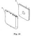
- FIG. 10is an exploded view of an internal antenna showing both the overmolded laminated substrate and a cover;
- FIG. 11is a perspective view of an internal antenna for use with an implantable medical device
- FIG. 12illustrates an interior view of a housing of an implantable medical device showing the positioning of a power source
- FIG. 13is a perspective view of a battery support for an implantable medical device
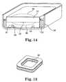
- FIG. 14is a cross-sectional view of an implantable medical device showing the placement and support of a battery
- FIG. 15is a perspective view an internal antenna about to be mated with a housing of implantable medical device
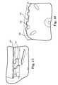
- FIG. 16is a detailed view of a portion of FIG. 15 illustrating an engagement tab
- FIG. 17is another detailed view of an engagement tab for an internal antenna
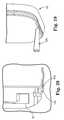
- FIG. 18is a top view of a portion of a housing for implantable medical device illustrating bottom rail engagement and fill hole;
- FIG. 19is a detailed view of internal antenna mounted to housing illustrating sealing implantable medical device using an adhesive needle
- FIG. 20is a cross-sectional view of a portion of internal antenna and housing illustrating a flow channel for an adhesive sealant
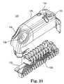
- FIG. 21is an exploded view of a connector block for use with an implantable medical device
- FIG. 22is a cross-sectional view of the connector block of FIG. 21 ;
- FIG. 23is a partial cross-section view of the connector block of FIG. 21 illustrating a chimney
- FIG. 24is an exploded view illustrating the assembly of internal antenna, housing and connector block of implantable medical device.
- FIG. 1shows implantable medical device 10 for example, a drug pump, implanted in patient 12 .
- the implantable medical device 10is typically implanted by a surgeon in a sterile surgical procedure performed under local, regional, or general anesthesia.
- a catheter 14is typically implanted with the distal end position at a desired location, or therapeutic delivery site 16 , in the body of patient 12 and the proximal end tunneled under the skin to the location where the medical device 10 is to be implanted.
- Implantable medical device 10is generally implanted subcutaneously at depths, depending upon application and device 10 , of from 1 centimeter (0.4 inches) to 2.5 centimeters (1 inch) where there is sufficient tissue to support the implanted system. Once medical device 10 is implanted into the patient 12 , the incision can be sutured closed and medical device 10 can begin operation.
- Implantable medical device 10operates to infuse a therapeutic substance into patient 12 .
- Implantable medical device 10can be used for a wide variety of therapies such as pain, spasticity, cancer, and many other medical conditions.
- the therapeutic substance contained in implantable medical device 10is a substance intended to have a therapeutic effect such as pharmaceutical compositions, genetic materials, biologics, and other substances.
- Pharmaceutical compositionsare chemical formulations intended to have a therapeutic effect such as intrathecal antispasmodics, pain medications, chemotherapeutic agents, and the like.
- Pharmaceutical compositionsare often configured to function in an implanted environment with characteristics such as stability at body temperature to retain therapeutic qualities, concentration to reduce the frequency of replenishment, and the like.
- Genetic materialsare substances intended to have a direct or indirect genetic therapeutic effect such as genetic vectors, genetic regulator elements, genetic structural elements, DNA, and the like.
- Biologicsare substances that are living matter or derived from living matter intended to have a therapeutic effect such as stem cells, platelets, hormones, biologically produced chemicals, and the like. Other substances may or may not be intended to have a therapeutic effect and are not easily classified such as saline solution, fluoroscopy agents, disease diagnostic agents and the like. Unless otherwise noted in the following paragraphs, a drug is synonymous with any therapeutic, diagnostic, or other substance that is delivered by the implantable infusion device.
- Implantable medical device 10can be any of a number of medical devices such as an implantable pulse generator, implantable therapeutic substance delivery device, implantable drug pump, cardiac pacemaker, cardioverter or defibrillator, as examples.
- Electrical power for implantable medical device 10can be contained in implantable medical device itself.
- Power source for implantable medical device 10can be any commonly known and readily available sources of power such as a chemical battery, electrical storage device, e.g., capacitor, a mechanical storage device, e.g., spring, or can be transcutaneously supplied in real time, or some combination.
- an inductive charging technique using an external primary coil and an internal secondary coilcan be utilized.
- FIG. 2illustrates an embodiment of implantable medical device 10 situated under cutaneous boundary 18 .
- Charging regulation module 20controls the charging of rechargeable power source 22 .
- Power source 22powers electronics module 24 which, in turn, controls therapy module 26 .
- charging regulation and therapy controlis conventional.
- Implantable medical device 10also has internal telemetry coil 28 configured in conventional manner to communicate through external telemetry coil 30 to an external programming device (not shown), charging unit 32 or other device in a conventional manner in order to both program and control implantable medical device and to externally obtain information from implantable medical device 10 once implantable medical device has been implanted.
- Internal telemetry coil 28rectangular in shape with dimensions of 1.85 inches (4.7 centimeters) by 1.89 inches (4.8 centimeters) constructed from 150 turns of 43 AWG wire, is sized to be larger than the diameter of secondary charging coil 34 .
- Secondary coil 34is constructed with 182 turns of 30 AWG wire with an inside diameter of 0.72 inches (1.83 centimeters) and an outside diameter of 1.43 inches (3.63 centimeters) with a height of 0.075 inches (0.19 centimeters).
- Magnetic shield 36is positioned between secondary charging coil 34 and housing 38 and sized to cover the footprint of secondary charging coil 34 .
- Internal telemetry coil 28having a larger diameter than secondary coil 34 , is not completely covered by magnetic shield 36 allowing implantable medical device 10 to communicate with the external programming device with internal telemetry coil 28 in spite of the presence of magnetic shield 36 .
- Rechargeable power source 24can be charged while implantable medical device 10 is in place in a patient through the use of external charging device 40 .
- external charging device 40consists of charging unit 32 and external antenna 42 .
- Charging unit 32contains the electronics necessary to drive primary coil 44 with an oscillating current in order to induce current in secondary coil 34 when primary coil 44 is placed in the proximity of secondary coil 34 .
- Charging unit 32is operatively coupled to primary coil by cable 46 .
- charging unit 32 and external antenna 42may be combined into a single unit.
- Antenna 42may also optionally contain external telemetry coil 30 which may be operatively coupled to charging unit 32 if it is desired to communicate to or from implantable medical device 10 with external charging device 40 .
- external antenna 42may optionally contain external telemetry coil 30 which can be operatively coupled to an external programming device, either individually or together with external charging unit 32 .
- Repositionable magnetic core 48can help to focus electromagnetic energy from primary coil 30 to more closely be aligned with secondary coil 34 .
- Energy absorptive material 50can help to absorb heat build-up in external antenna 42 which will also help allow for a lower temperature in implantable medical device 10 and/or help lower recharge times.
- Thermally conductive material 52is positioned covering at least a portion of the surface of external antenna 42 which contacts cutaneous boundary 18 of patient 12 . Thermally conductive material 52 positioned on the surface of external charging device 40 in order to distribute any heat which may be generated by external charging device 40 .
- Secondary coil 34is located in internal antenna 54 that is separable from housing 38 .
- Magnetic shield 56is positioned between secondary coil 34 and housing 38 and inside the diameter of internal telemetry coil 28 to help isolate the remainder of implantable medical device 10 from electromagnetic energy from external charging device 40 .
- Base laminate 58is constructed of a plurality of layers, preferably three layers, of MetglasTM material 59 secured together by a suitable adhesive, such as Pyralux® acrylic adhesive. Each layer of MetglasTM material 59 is approximately 0.001 inch (0.0254 millimeters) thick. Eight eddy current grooves 60 are radially etched by laser into one side of the layers of MetglasTM material 59 at approximately equal radial spacings. An insulative layer of polyimide is adhesively secured to each side of MetglasTM laminate resulting in a base laminate 58 approximately 0.15 inches (3.8 millimeters) thick. Base laminate 58 is approximately 1.54 inches (39 millimeters) square with two rounded comers to facilitate subsequent assembly.
- Lead wires 62are placed ( FIG. 5 ) onto base laminate 58 with ends positioned at locations adapted to connect with wires from a coil to added to base laminate 58 .
- Lead wires 62are placed inboard and, generally, away from cutouts for hub 64 and feet 66 .
- lead wires 62are flat 0.004 inch (0.10 millimeters) and round 0.015 inch (0.38 millimeters) in locations 70 and 72 exiting base laminate 58 .
- lead wires 62are made from niobium ribbon wire.
- lead wires 62are secured in place by adhesively securing another layer 63 of polyimide to the side of base laminate 58 onto which lead wires 62 have been positioned.
- the resulting structureforms a coil ready coreless laminate 68 ready to receive a coil of wire that forms secondary coil 34 .
- Pre-placing lead wires 62 onto base laminate 58reduces stress from normal movement of lead wires 62 and aids in further assembly.
- secondary coil 34Prior to being placed onto the surface of coil ready coreless laminate 68 , secondary coil 34 is preferably coated in a siloxane coating process. Secondary coil 34 is placed in a vacuum chamber that is then evacuated to 0.10 torr vacuum and held for ten (10) minutes. 10 sccm of Hexamethyldisiloxane, 30 sccm of Nitrous oxide and 1 sccm of Argon are pumped into the chamber. Approximately 150 watts of power to ignite the plasma for thirty (30) seconds.
- secondary coil 34is then placed onto the surface of coil ready coreless laminate 68 and electrically connected to lead wires 62 at locations 70 and 72 by welding or, preferably, opposed welding.
- Cross-over copper wire 74 from secondary coil 34makes electrical connection at location 72 .
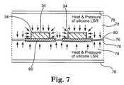
- the resulting substrate 80is then sandwiched between a cover sheet 76 of polyimide secured with a thermoset adhesive as illustrated in FIG. 7 .
- Substrate 80is placed into a press between polyimide cover sheets 76 which, of course, can be added either before or after substrate 80 is placed into the press.
- a thermoset adhesivepreferably Pyralux® acrylic adhesive, is located between substrate 80 and cover sheets 76 .
- thermoset polymersuch as liquid silicone rubber
- Heatpreferably approximately 340 degrees Fahrenheit
- pressurepreferably approximately 1,200 pounds per square inch (8,274 pascals)
- the use of a liquid material in the pressallows the press to apply force evenly against the irregular upper surface of substrate 80 .
- the thermoset polymeris allowed to cure under heat and pressure for approximately five (5) minutes forming an at least partially cured silicone rubber sheet on either side of substrate 80 and allowed to cool for approximately twenty (20) minutes.
- the assemblycan then be removed from the mold and the silicone rubber sheets removed (peeled) away and discarded leaving the laminated substrate 80 .
- the pressis only used during while the liquid thermoset polymer is being pressed to substrate 80 .
- the laminated substrate 80may be removed from the press.
- the laminated substrate 80can continue to be allowed to cool outside of the press, e.g., for approximately twenty (20) minutes.
- the pressmay be used again to produce a second laminated substrate 80 . Since the laminated substrate 80 need only remain in the press during the initial stages (first five (5) minutes) for curing, the press may be used to produce a second laminated substrate 80 while the first laminated substrate 80 continues to cool.
- the early re-use of the pressas compared with having to along laminated substrate to remain in the press for the entire cooling time, is a consider savings in equipment time and allows a greatly increased efficiency of operation.
- Laminated substrate 80is then overmolded to seal laminated substrate in an environment better able to withstand the harmful effects of bodily fluids after implantation.
- the overmoldingtakes place in two steps.
- a plurality of support feet 82are placed on one side, preferably the underside, of laminated substrate 80 .
- Support feet 82may be molded onto the underside of laminated substrate 80 using conventional molding techniques.
- support feet 82may be adhesively attached, e.g., with glue, may be ultrasonically staked or may be otherwise mechanically attached, e.g., by threaded fastener.
- Support feet 82may be equally spaced somewhat near each of the four corners of laminated substrate 80 .
- support feethave a circular cross-section.
- hub 84is also molded, or otherwise mechanically attached, to laminated substrate surrounding a central hole in laminated substrate.
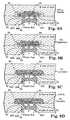
- FIGS. 9A , 9 B, 9 C and 9 DThe second part of the overmolding process is illustrated in FIGS. 9A , 9 B, 9 C and 9 D.
- laminated substrate 90 with support feet 82 and hub 84is placed into an injection mold.
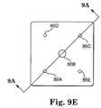
- Injection material 85preferably polysulfone, is introduced into the mold through five (5) injection holes ( 86 A, 86 B, 86 C, 86 D and 86 E) from one side of the injection mold.
- injection holes86 A, 86 B, 86 C, 86 D and 86 E
- FIGS. 9A , 9 B, 9 C and 9 Drepresent a cross-sectional view of the injection mold. Although a total of five (5) injection holes are utilized, only three (3) are visible in the cross-sectional view.
- One (1) injection holeis used for the hub (injection hole 86 B).
- injection holes 86 D and 86 Eare not visible in the cross-sectional view in FIG. 9A .
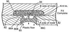
- Injection material 85begins to flow into the underside of laminated substrate 80 through injection holes 86 A and 86 C. Injection material 85 also begins to flow through hub 84 and spreads out over the topside of laminated substrate 80 through injection hole 86 B. In FIG. 9E
- injection material 85continues to flow into the injection mold through the five (5) injection holes ( 86 A, 86 B, 86 C, 86 D and 86 E) in a manner such that the amount of injection material 85 flowing over the topside of laminated substrate 80 and the amount of injection material 85 flowing over the underside of laminated substrate 80 is such that mechanical forces against laminated substrate 80 are evened out from topside and underside.
- thisis expected to occur when injection material 85 flows at approximately the same rate over the topside of laminated substrate 80 as over the underside of laminated substrate 90 . That is, injection material 85 on the topside of laminated substrate 80 is forcing against the topside of laminated substrate 80 with about the same amount of force that injection material 85 is forcing against the underside of laminated substrate 80 .
- injection material 85continues to flow evenly over the topside and the underside of laminated substrate 80 .
- injection material 85has filled the injection mold essentially filling all of the cavity of the injection mold resulting in an overmolded laminated substrate 80 .
- Injection holes 86 A, 86 B, 86 C, 86 D and 86 Eare chosen in size such to facilitate the even flow of injection material 85 . If injection material 85 does not flow evenly over both the topside and the underside of laminated substrate 80 , the resultant overmolded part can warp following cooling.
- injection material 85flows around support feet 82 and encircles each of circular support feet 82 .
- injection material 85has a tendency to shrink.
- shrinkage of injection materialmay create a crack or a gap which may create an area into which bodily fluids could subsequently gain entry following implantation.
- hub 84By encircling each of support feet 82 , such shrinkage of injection material 85 will actually cause injection material to form more tightly around support feet 82 creating an even stronger bond and helping to ensure that bodily fluids can not gain entry following implantation.
- Hub 84has a circular cross-section and has surrounding a indentation which allow injection material 85 to surround hub 84 and shrink more tightly to hub 84 as injection material 85 cools creating a stronger bond and less likelihood of leaks.
- Overmolded cover 90created in FIGS. 9A , 9 B, 9 C and 9 D, by overmolding laminated substrate 88 in an injection mold, is shown in FIG. 10 with polysulfone cover 85 .
- Cover 90is mechanically joined with overmolded substrate 88 in a conventional manner to complete the assembly of internal 54 (shown in FIG. 11 ).
- FIG. 12shows housing 38 of portion of implantable medical device 10 holding power source 22 , electronics module 24 and other components.
- Power sourcepreferably a battery
- Power source 22is located in area 92 in housing 38 . It is desirable that battery 22 be reasonably secured within housing 38 but at the same be allowed to expand and contract with use. Chemical batteries, such as battery 22 , may have a tendency to expand as the battery 22 is charged and subsequently contract as the battery 22 ceases to be charged. Such expansion and contraction in a battery 22 which is very tightly secured in housing 38 might cause battery 22 to either come loose from its attachments and/or compromise its electrical connections.
- battery 22is held in a manner which allows battery 22 to expand, e.g., during charging, and subsequently contract, e.g., following charging, without compromising mechanical and/or electrical connections.
- Spacer 94seen more clearly in FIG. 13 , supports battery 22 around the periphery of battery 22 while cutout 96 in the central portion of spacer 94 allows battery 22 to expand without compromise.
- battery 22has a rectangular shape with major and minor sides.
- spacer 94supports a major side of battery 22 while allowing cutout 96 to allow expansion of the major side of battery 22 .
- spacer 94is constructed with a layer of polyimide approximately 0.001 inch (0.0254 millimeters) thick.
- spacer 94is secured in an inside surface of housing 38 with a suitable adhesive (see FIG. 14 ).
- battery 22fits inside battery cup 97 supported by spacer 94 , is allowed to expand, e.g., during charge, as illustrated by expansion dotted lines 98 .
- epoxy 100is introduced into housing 38 to help secure battery 22 .
- Battery cup 97 and spacer 94will help to ensure that epoxy 100 does not fill the space created by spacer 94 .
- FIGS. 15 through 20illustrate the mechanical connection of internal antenna 54 to housing 38 to achieve an integrated implantable medical device 10 that will be able to withstand the ravages of bodily fluids once implanted.
- Housing 38has a recharge rail 102 extending around three sides that is adapted to slideably mate with a complementary rail 104 on internal antenna 54 .
- electrical connector wires 106inhibit rail 104 of internal antenna 54 from engaging recharge rail 102 from the open end. While electrical connector wires could be bent and then reformed to the illustrated position following installation of internal antenna 54 onto housing 38 , this is not desirable from a reliability standpoint, due to the bending and straightening of wires 106 , it is also inefficient.
- Recharge rail 102has a drop opening 108 allowing tab 110 of internal antenna 54 to drop into opening 108 and then allow rail 104 to slidably engage recharge rail 102 which are configured to slidably engage over a portion of the sliding distance.
- This “drop and slide” engagementallows internal antenna 54 to drop avoiding interference with electrical connection wires 106 and still slidably securely engage to housing 38 .
- Detent 112provides tactile feedback to the installer to know when proper sliding engagement is achieved.
- locking tab 114may be purposely bent up to engage the rear of rail 104 preventing internal antenna 54 from disengaging with housing 38 . It is to be recognized and understood that all of these engaging and locking mechanisms preferably exist on both sides of implantable medical device 10 in complementary fashion even though the drawings illustrate only one side.
- An adhesive channel 116is formed around the perimeter of housing 38 .
- Fill hole 118communicates through both internal antenna 54 and housing 38 to allow an adhesive needle 120 to be inserted.
- Adhesive needle 120may then be used to fill adhesive channel 116 , through fill hole 118 , with adhesive providing another layer of sealing for implantable medical device 10 .
- electrical connector wires 106may be connected using connector block 122 as shown in FIGS. 21 , 22 , 23 and 24 .
- Rigid polysulfone frame 124provides structural rigidity to connector block 122 .
- Frame 124is laid out in linear fashion so that all electrical connections are in a linear row.
- Wire frame 126is stamped out of a conductive material, preferably a metal. Since rigid frame 124 is laid out linearly, wire frame 126 can be stamped with a plurality of linear connector areas.
- Wire frame 126is joined with rigid frame 124 and mated with electrical connector wires 106 .
- Frame cover 128fits over rigid frame 124 .
- thermoset polymersuch as silicone rubber
- a biocompatible thermoset polymersuch as silicone rubber
- the thermoset polymeralso provides electrical isolation between the electrical contacts of wire frame 126 .
- Connector block 122has a plurality of openings 130 allowing an external electrical connection with implantable medical device 10 .
- Chimneys 132form a void near the external electrical contact openings allowing the thermoset polymer to at least partially fill chimney 132 to further seal and secure an electrical connection opening into implantable medical device 10 .
- Such thermoset polymeralso provides a strain relief for the lead used for the external electrical connection.
- Grommets 134which are compatible with thermoset polymer, additionally secure and electrically isolate the external electrical connection.
- a set screw 136may be used to mechanically secure the external wire to connector block 122 .
- thermoset polymersubstantially fills voids within connector block 122 , thermoset polymer forms a skirt, when cured, that is usually thinner than is reasonably possible to be created with rigid frame 124 or thermoplastic cover 128 .
- the thinner skirt achieved with the thermoset polymerallows an even stronger and more secure seal against the intrusion of body fluids.
- rigid frameis treated before assembly with an adhesion promoter to create a stronger bond between rigid frame 124 and thermoset polymer.
- the surface of polysulfone rigid frame 124is cleaned with a detergent, preferably Micro 90TM detergent, rinsed first in D.I. water and then rinsed in IPA.
- Polysulfone rigid frame 124is plasma treated by first being placed in a vacuum chamber that is then evacuated to 0.10 torr vacuum and held for ten (10) minutes. 10 sccm of Hexamethyldisiloxane, 30 sccm of Nitrous oxide and 1 sccm of Argon are pumped into the chamber. Approximately 150 watts of power to ignite the plasma for thirty (30) seconds.
- Rigid frame 124is then coated by being dipped into a twenty percent (20%) solution of RTV medical silicone adhesive and heptane by weight for approximately two (2) seconds. Rigid frame 124 is then removed from the dip and cured in an oven at 150 degrees Centigrade for eight (8) hours.
Landscapes
- Engineering & Computer Science (AREA)
- Health & Medical Sciences (AREA)
- Life Sciences & Earth Sciences (AREA)
- Mechanical Engineering (AREA)
- Manufacturing & Machinery (AREA)
- Public Health (AREA)
- Animal Behavior & Ethology (AREA)
- General Health & Medical Sciences (AREA)
- Radiology & Medical Imaging (AREA)
- Veterinary Medicine (AREA)
- Nuclear Medicine, Radiotherapy & Molecular Imaging (AREA)
- Biomedical Technology (AREA)
- Biophysics (AREA)
- Heart & Thoracic Surgery (AREA)
- Electrotherapy Devices (AREA)
- Prostheses (AREA)
- Injection Moulding Of Plastics Or The Like (AREA)
- Materials For Medical Uses (AREA)
Abstract
Description
Claims (9)
Priority Applications (6)
| Application Number | Priority Date | Filing Date | Title |
|---|---|---|---|
| US10/836,096US7955543B2 (en) | 2004-04-30 | 2004-04-30 | Method of overmolding a substrate |
| PCT/US2004/031663WO2005110702A1 (en) | 2004-04-30 | 2004-09-22 | Method of overmolding a substrate and product made by that process |
| EP04785137AEP1744865B1 (en) | 2004-04-30 | 2004-09-22 | Method of overmolding a substrate for an implantable medical device and substrate made by that process |
| DE602004019985TDE602004019985D1 (en) | 2004-04-30 | 2004-09-22 | METHOD FOR FORMING A SUBSTRATE FOR AN IMPLANTABLE MEDICAL DEVICE AND SUBSTRATE MANUFACTURED BY THIS METHOD |
| AT04785137TATE424982T1 (en) | 2004-04-30 | 2004-09-22 | METHOD FOR FORMING A SUBSTRATE FOR AN IMPLANTABLE MEDICAL DEVICE AND SUBSTRATE PRODUCED BY SUCH METHOD |
| US11/429,706US20060204717A1 (en) | 2004-04-30 | 2006-05-08 | Overmolded substrate |
Applications Claiming Priority (1)
| Application Number | Priority Date | Filing Date | Title |
|---|---|---|---|
| US10/836,096US7955543B2 (en) | 2004-04-30 | 2004-04-30 | Method of overmolding a substrate |
Related Child Applications (1)
| Application Number | Title | Priority Date | Filing Date |
|---|---|---|---|
| US11/429,706DivisionUS20060204717A1 (en) | 2004-04-30 | 2006-05-08 | Overmolded substrate |
Publications (2)
| Publication Number | Publication Date |
|---|---|
| US20050244611A1 US20050244611A1 (en) | 2005-11-03 |
| US7955543B2true US7955543B2 (en) | 2011-06-07 |
Family
ID=34958836
Family Applications (2)
| Application Number | Title | Priority Date | Filing Date |
|---|---|---|---|
| US10/836,096Expired - Fee RelatedUS7955543B2 (en) | 2004-04-30 | 2004-04-30 | Method of overmolding a substrate |
| US11/429,706AbandonedUS20060204717A1 (en) | 2004-04-30 | 2006-05-08 | Overmolded substrate |
Family Applications After (1)
| Application Number | Title | Priority Date | Filing Date |
|---|---|---|---|
| US11/429,706AbandonedUS20060204717A1 (en) | 2004-04-30 | 2006-05-08 | Overmolded substrate |
Country Status (5)
| Country | Link |
|---|---|
| US (2) | US7955543B2 (en) |
| EP (1) | EP1744865B1 (en) |
| AT (1) | ATE424982T1 (en) |
| DE (1) | DE602004019985D1 (en) |
| WO (1) | WO2005110702A1 (en) |
Cited By (11)
| Publication number | Priority date | Publication date | Assignee | Title |
|---|---|---|---|---|
| US9042997B2 (en) | 2009-11-11 | 2015-05-26 | Boston Scientific Neuromodulation Corporation | Minimizing interference between charging and telemetry coils in an implantable medical device |
| US9061159B2 (en) | 2009-11-11 | 2015-06-23 | Boston Scientific Neuromodulation Corporation | Using the case of an implantable medical device to broaden communication bandwidth |
| US9242107B2 (en) | 2013-07-12 | 2016-01-26 | Cardiac Pacemarkers, Inc. | Seal plug |
| US9480849B2 (en) | 2013-07-12 | 2016-11-01 | Cardiac Pacemakers, Inc. | Method of overmoulding top mounted seal plug cavities |
| US20170165493A1 (en)* | 2015-12-15 | 2017-06-15 | Pacesetter, Inc. | Systems and Methods for Manufacturing Header Subassembly |
| US9820733B2 (en) | 2013-07-12 | 2017-11-21 | Cardiac Pacemakers, Inc. | Moulded in place seal plug and suture anchor |
| US10281108B2 (en)* | 2017-03-20 | 2019-05-07 | Valeo North America, Inc. | Interlocking joints for injection molded part |
| EP3466330A4 (en)* | 2016-05-27 | 2019-12-25 | Todoc Co., Ltd. | BIO-IMPLANTABLE DEVICE AND ITS MANUFACTURING METHOD |
| US10646719B2 (en) | 2009-07-31 | 2020-05-12 | Medtronic, Inc. | Implantable medical devices including baseplates having separate bodies of material thereon |
| US11224753B1 (en) | 2010-12-28 | 2022-01-18 | Medtronic, Inc. | Medical devices including connector enclosures with feedthrough passageways |
| US12179028B2 (en) | 2009-07-31 | 2024-12-31 | Medtronic, Inc. | Implantable medical device |
Families Citing this family (13)
| Publication number | Priority date | Publication date | Assignee | Title |
|---|---|---|---|---|
| US8673194B2 (en)* | 2007-05-04 | 2014-03-18 | Medtronic, Inc. | Method for forming a connector for an implantable medical device |
| WO2010059348A1 (en)* | 2008-11-20 | 2010-05-27 | Cardiac Pacemakers, Inc. | Overmolded components for implantable medical leads and related methods |
| US20110266713A1 (en)* | 2008-12-18 | 2011-11-03 | Graeme Vincent | Method of encapsulation of a flexible component |
| KR101079496B1 (en) | 2009-08-10 | 2011-11-03 | 삼성전기주식회사 | Antenna pattern frame, method and mould for manufacturing the same, electronic device having antenna pattern frame embeded therein and method for manufacturing the same |
| JP2013516222A (en) | 2009-12-30 | 2013-05-13 | カーディアック ペースメイカーズ, インコーポレイテッド | Tapered drug-eluting color for medical electrical leads |
| EP2773423B1 (en)* | 2011-11-04 | 2024-01-10 | Nevro Corporation | Medical device communication and charding assemblies for use with implantable signal generators |
| US20150092360A1 (en)* | 2013-10-01 | 2015-04-02 | Nike, Inc. | Battery overmolding |
| PT3193696T (en) | 2014-09-17 | 2021-02-04 | Richard M Levitan | Introducer for tracheal tube intubation |
| US20170050027A1 (en) | 2015-08-18 | 2017-02-23 | Marcus ANDERSSON | Implantable Magnet Arrangements |
| GB201519582D0 (en)* | 2015-11-05 | 2015-12-23 | Intersurgical Ag | Improvements relating to the manufacture of medical devices |
| GB2547017B (en) | 2016-02-04 | 2021-08-04 | Intersurgical Ag | Improvements to intubation aids |
| JP2019506953A (en)* | 2016-02-22 | 2019-03-14 | ザ チャールズ スターク ドレイパー ラボラトリー インク | Method of manufacturing an implantable neural electrode interface platform |
| CN109501125A (en)* | 2019-01-26 | 2019-03-22 | 庐江凯胜塑胶有限公司 | A kind of double-colored plus in-molded power button injection molding process method |
Citations (39)
| Publication number | Priority date | Publication date | Assignee | Title |
|---|---|---|---|---|
| US3357434A (en) | 1964-04-06 | 1967-12-12 | Avco Corp | Inductively linked receiver |
| US3888260A (en) | 1972-06-28 | 1975-06-10 | Univ Johns Hopkins | Rechargeable demand inhibited cardiac pacer and tissue stimulator |
| US3895229A (en)* | 1972-11-14 | 1975-07-15 | Holger Strom | Hollow shell-like bodies and element for use in construction of same |
| US4041955A (en) | 1976-01-29 | 1977-08-16 | Pacesetter Systems Inc. | Implantable living tissue stimulator with an improved hermetic metal container |
| US4071032A (en) | 1976-01-29 | 1978-01-31 | Pacesetter Systems Inc. | Implantable living tissue stimulators |
| US4134408A (en) | 1976-11-12 | 1979-01-16 | Research Corporation | Cardiac pacer energy conservation system |
| US4186749A (en) | 1977-05-12 | 1980-02-05 | The United States Of America As Represented By The Administrator Of The National Aeronautics And Space Administration | Induction powered biological radiosonde |
| JPS5816839A (en) | 1981-07-24 | 1983-01-31 | Sumitomo Rubber Ind Ltd | Method of vulcanizing elastomer product |
| EP0499939A1 (en) | 1991-02-13 | 1992-08-26 | IMPLEX GmbH Spezialhörgeräte | Charging system for implantable hearing aids and Tinnitus masks |
| US5314457A (en) | 1993-04-08 | 1994-05-24 | Jeutter Dean C | Regenerative electrical |
| US5411537A (en) | 1993-10-29 | 1995-05-02 | Intermedics, Inc. | Rechargeable biomedical battery powered devices with recharging and control system therefor |
| US5527348A (en) | 1995-02-03 | 1996-06-18 | Medtronic, Inc. | Magnetically permeable E-shield and method of connection thereto |
| US5562714A (en) | 1995-02-03 | 1996-10-08 | Medtronic, Inc. | Magnetic field strength regulator for implant |
| US5613935A (en) | 1994-12-16 | 1997-03-25 | Jarvik; Robert | High reliability cardiac assist system |
| US5690693A (en) | 1995-06-07 | 1997-11-25 | Sulzer Intermedics Inc. | Transcutaneous energy transmission circuit for implantable medical device |
| EP0811395A2 (en) | 1996-06-07 | 1997-12-10 | Quest Medical, Inc. | Multiprogrammable tissue stimulator |
| US5713939A (en) | 1996-09-16 | 1998-02-03 | Sulzer Intermedics Inc. | Data communication system for control of transcutaneous energy transmission to an implantable medical device |
| US5714106A (en) | 1993-12-29 | 1998-02-03 | Nichias Corporation | Process of producing a device including a molded-in insert and fluoroplastic surfacing material |
| US5733313A (en) | 1996-08-01 | 1998-03-31 | Exonix Corporation | RF coupled, implantable medical device with rechargeable back-up power source |
| WO1998037926A1 (en) | 1997-02-26 | 1998-09-03 | Alfred E. Mann Foundation For Scientific Research | Battery-powered patient implantable device |
| US5861019A (en) | 1997-07-25 | 1999-01-19 | Medtronic Inc. | Implantable medical device microstrip telemetry antenna |
| WO1999006108A1 (en) | 1997-08-01 | 1999-02-11 | Alfred E. Mann Foundation For Scientific Research | Implantable device with improved battery recharging and powering configuration |
| WO1999044684A1 (en) | 1998-03-06 | 1999-09-10 | Dew Engineering And Development Limited | Transcutaneous energy transfer device |
| WO2000001442A2 (en) | 1998-07-06 | 2000-01-13 | Abiomed, Inc. | Transcutaneous energy transfer device with magnetic field protected components in secondary coil |
| EP1048324A2 (en) | 1999-04-30 | 2000-11-02 | Medtronic, Inc. | Medical Li+ rechargeable powered implantable stimulator |
| US6154677A (en) | 1998-08-20 | 2000-11-28 | Implex Aktiengesellschaft Hearing Technology | Implantable device with a charging current feed arrangement which has a receiving coil |
| US6178353B1 (en) | 1998-07-27 | 2001-01-23 | Advanced Bionics Corporation | Laminated magnet keeper for implant device |
| US6275737B1 (en) | 1998-10-14 | 2001-08-14 | Advanced Bionics Corporation | Transcutaneous transmission pouch |
| US6308101B1 (en) | 1998-07-31 | 2001-10-23 | Advanced Bionics Corporation | Fully implantable cochlear implant system |
| WO2001083029A1 (en) | 2000-04-28 | 2001-11-08 | Medtronic, Inc. | Battery recharge management for an implantable medical device |
| US6319448B1 (en) | 1998-05-18 | 2001-11-20 | Remy Kirchdoerffer | Process for the production of an apparatus or instrument by overmolding and apparatus or instrument thus obtained |
| US6324430B1 (en) | 1998-07-06 | 2001-11-27 | Abiomed, Inc. | Magnetic shield for primary coil of transcutaneous energy transfer device |
| WO2001097908A2 (en) | 2000-06-16 | 2001-12-27 | Medtronic, Inc. | An implantable medical device with aregarding coil magnetic shield |
| US20020021549A1 (en) | 2000-06-19 | 2002-02-21 | Tsutomu Kono | Hybrid housing of metal board and synthetic resin |
| US20020171169A1 (en) | 2001-05-18 | 2002-11-21 | Chao-Yueh Chuang | Process for forming a molded plastic layer on a metal plate |
| US6505077B1 (en) | 2000-06-19 | 2003-01-07 | Medtronic, Inc. | Implantable medical device with external recharging coil electrical connection |
| US6516227B1 (en) | 1999-07-27 | 2003-02-04 | Advanced Bionics Corporation | Rechargeable spinal cord stimulator system |
| US20030049413A1 (en) | 2001-09-10 | 2003-03-13 | Packer Bradford P. | Method of applying ablative insulation coatings and articles obtained therefrom |
| US20030116886A1 (en)* | 2001-12-25 | 2003-06-26 | Makoto Nakazawa | Composite-molding method and injection-molding machine of different material resin |
- 2004
- 2004-04-30USUS10/836,096patent/US7955543B2/ennot_activeExpired - Fee Related
- 2004-09-22WOPCT/US2004/031663patent/WO2005110702A1/enactiveApplication Filing
- 2004-09-22EPEP04785137Apatent/EP1744865B1/ennot_activeExpired - Lifetime
- 2004-09-22ATAT04785137Tpatent/ATE424982T1/ennot_activeIP Right Cessation
- 2004-09-22DEDE602004019985Tpatent/DE602004019985D1/ennot_activeExpired - Lifetime
- 2006
- 2006-05-08USUS11/429,706patent/US20060204717A1/ennot_activeAbandoned
Patent Citations (44)
| Publication number | Priority date | Publication date | Assignee | Title |
|---|---|---|---|---|
| US3357434A (en) | 1964-04-06 | 1967-12-12 | Avco Corp | Inductively linked receiver |
| US3888260A (en) | 1972-06-28 | 1975-06-10 | Univ Johns Hopkins | Rechargeable demand inhibited cardiac pacer and tissue stimulator |
| US3895229A (en)* | 1972-11-14 | 1975-07-15 | Holger Strom | Hollow shell-like bodies and element for use in construction of same |
| US4041955A (en) | 1976-01-29 | 1977-08-16 | Pacesetter Systems Inc. | Implantable living tissue stimulator with an improved hermetic metal container |
| US4071032A (en) | 1976-01-29 | 1978-01-31 | Pacesetter Systems Inc. | Implantable living tissue stimulators |
| US4134408A (en) | 1976-11-12 | 1979-01-16 | Research Corporation | Cardiac pacer energy conservation system |
| US4186749A (en) | 1977-05-12 | 1980-02-05 | The United States Of America As Represented By The Administrator Of The National Aeronautics And Space Administration | Induction powered biological radiosonde |
| JPS5816839A (en) | 1981-07-24 | 1983-01-31 | Sumitomo Rubber Ind Ltd | Method of vulcanizing elastomer product |
| EP0499939B1 (en) | 1991-02-13 | 1994-08-10 | IMPLEX GmbH Spezialhörgeräte | Charging system for implantable hearing aids and Tinnitus masks |
| EP0499939A1 (en) | 1991-02-13 | 1992-08-26 | IMPLEX GmbH Spezialhörgeräte | Charging system for implantable hearing aids and Tinnitus masks |
| US5279292A (en) | 1991-02-13 | 1994-01-18 | Implex Gmbh | Charging system for implantable hearing aids and tinnitus maskers |
| US5314457A (en) | 1993-04-08 | 1994-05-24 | Jeutter Dean C | Regenerative electrical |
| US5411537A (en) | 1993-10-29 | 1995-05-02 | Intermedics, Inc. | Rechargeable biomedical battery powered devices with recharging and control system therefor |
| US5714106A (en) | 1993-12-29 | 1998-02-03 | Nichias Corporation | Process of producing a device including a molded-in insert and fluoroplastic surfacing material |
| US5613935A (en) | 1994-12-16 | 1997-03-25 | Jarvik; Robert | High reliability cardiac assist system |
| US5527348A (en) | 1995-02-03 | 1996-06-18 | Medtronic, Inc. | Magnetically permeable E-shield and method of connection thereto |
| US5562714A (en) | 1995-02-03 | 1996-10-08 | Medtronic, Inc. | Magnetic field strength regulator for implant |
| US5690693A (en) | 1995-06-07 | 1997-11-25 | Sulzer Intermedics Inc. | Transcutaneous energy transmission circuit for implantable medical device |
| EP0811395A2 (en) | 1996-06-07 | 1997-12-10 | Quest Medical, Inc. | Multiprogrammable tissue stimulator |
| EP0811395A3 (en) | 1996-06-07 | 1999-12-01 | Quest Medical, Inc. | Multiprogrammable tissue stimulator |
| US5733313A (en) | 1996-08-01 | 1998-03-31 | Exonix Corporation | RF coupled, implantable medical device with rechargeable back-up power source |
| US5713939A (en) | 1996-09-16 | 1998-02-03 | Sulzer Intermedics Inc. | Data communication system for control of transcutaneous energy transmission to an implantable medical device |
| WO1998037926A1 (en) | 1997-02-26 | 1998-09-03 | Alfred E. Mann Foundation For Scientific Research | Battery-powered patient implantable device |
| US5861019A (en) | 1997-07-25 | 1999-01-19 | Medtronic Inc. | Implantable medical device microstrip telemetry antenna |
| WO1999006108A1 (en) | 1997-08-01 | 1999-02-11 | Alfred E. Mann Foundation For Scientific Research | Implantable device with improved battery recharging and powering configuration |
| US6067474A (en) | 1997-08-01 | 2000-05-23 | Advanced Bionics Corporation | Implantable device with improved battery recharging and powering configuration |
| WO1999044684A1 (en) | 1998-03-06 | 1999-09-10 | Dew Engineering And Development Limited | Transcutaneous energy transfer device |
| US6319448B1 (en) | 1998-05-18 | 2001-11-20 | Remy Kirchdoerffer | Process for the production of an apparatus or instrument by overmolding and apparatus or instrument thus obtained |
| WO2000001442A2 (en) | 1998-07-06 | 2000-01-13 | Abiomed, Inc. | Transcutaneous energy transfer device with magnetic field protected components in secondary coil |
| US6324430B1 (en) | 1998-07-06 | 2001-11-27 | Abiomed, Inc. | Magnetic shield for primary coil of transcutaneous energy transfer device |
| US6178353B1 (en) | 1998-07-27 | 2001-01-23 | Advanced Bionics Corporation | Laminated magnet keeper for implant device |
| US6308101B1 (en) | 1998-07-31 | 2001-10-23 | Advanced Bionics Corporation | Fully implantable cochlear implant system |
| US6154677A (en) | 1998-08-20 | 2000-11-28 | Implex Aktiengesellschaft Hearing Technology | Implantable device with a charging current feed arrangement which has a receiving coil |
| US6275737B1 (en) | 1998-10-14 | 2001-08-14 | Advanced Bionics Corporation | Transcutaneous transmission pouch |
| EP1048324A2 (en) | 1999-04-30 | 2000-11-02 | Medtronic, Inc. | Medical Li+ rechargeable powered implantable stimulator |
| US6516227B1 (en) | 1999-07-27 | 2003-02-04 | Advanced Bionics Corporation | Rechargeable spinal cord stimulator system |
| WO2001083029A1 (en) | 2000-04-28 | 2001-11-08 | Medtronic, Inc. | Battery recharge management for an implantable medical device |
| WO2001097908A2 (en) | 2000-06-16 | 2001-12-27 | Medtronic, Inc. | An implantable medical device with aregarding coil magnetic shield |
| WO2001097908A3 (en) | 2000-06-16 | 2002-05-23 | Medtronic Inc | An implantable medical device with aregarding coil magnetic shield |
| US20020021549A1 (en) | 2000-06-19 | 2002-02-21 | Tsutomu Kono | Hybrid housing of metal board and synthetic resin |
| US6505077B1 (en) | 2000-06-19 | 2003-01-07 | Medtronic, Inc. | Implantable medical device with external recharging coil electrical connection |
| US20020171169A1 (en) | 2001-05-18 | 2002-11-21 | Chao-Yueh Chuang | Process for forming a molded plastic layer on a metal plate |
| US20030049413A1 (en) | 2001-09-10 | 2003-03-13 | Packer Bradford P. | Method of applying ablative insulation coatings and articles obtained therefrom |
| US20030116886A1 (en)* | 2001-12-25 | 2003-06-26 | Makoto Nakazawa | Composite-molding method and injection-molding machine of different material resin |
Non-Patent Citations (3)
| Title |
|---|
| Medtronic, Inc. "Implantable Neurostimulation Systems", 1998. |
| Medtronic, Inc. "Mattrix Neurostimulation System", Brochure, 1995. |
| Sinha, Gunjan, "The Heart, Medicine & Health", Popular Science, p. 43, Feb. 2000. |
Cited By (20)
| Publication number | Priority date | Publication date | Assignee | Title |
|---|---|---|---|---|
| US11806519B2 (en) | 2009-07-31 | 2023-11-07 | Medtronic, Inc. | Machining of enclosures for implantable medical devices |
| US11051905B2 (en) | 2009-07-31 | 2021-07-06 | Medtronic, Inc. | Implantable medical devices with enclosures including top and bottom end caps |
| US11090499B2 (en) | 2009-07-31 | 2021-08-17 | Medtronic, Inc. | Implantable medical device |
| US10646719B2 (en) | 2009-07-31 | 2020-05-12 | Medtronic, Inc. | Implantable medical devices including baseplates having separate bodies of material thereon |
| US12179028B2 (en) | 2009-07-31 | 2024-12-31 | Medtronic, Inc. | Implantable medical device |
| US11944826B2 (en) | 2009-07-31 | 2024-04-02 | Medtronic, Inc. | Implantable medical device |
| US9061159B2 (en) | 2009-11-11 | 2015-06-23 | Boston Scientific Neuromodulation Corporation | Using the case of an implantable medical device to broaden communication bandwidth |
| US9042997B2 (en) | 2009-11-11 | 2015-05-26 | Boston Scientific Neuromodulation Corporation | Minimizing interference between charging and telemetry coils in an implantable medical device |
| US11224753B1 (en) | 2010-12-28 | 2022-01-18 | Medtronic, Inc. | Medical devices including connector enclosures with feedthrough passageways |
| US9480849B2 (en) | 2013-07-12 | 2016-11-01 | Cardiac Pacemakers, Inc. | Method of overmoulding top mounted seal plug cavities |
| US9820733B2 (en) | 2013-07-12 | 2017-11-21 | Cardiac Pacemakers, Inc. | Moulded in place seal plug and suture anchor |
| US9511235B2 (en) | 2013-07-12 | 2016-12-06 | Cardiac Pacemakers, Inc. | Seal plug |
| US10850106B2 (en) | 2013-07-12 | 2020-12-01 | Cardiac Pacemakers, Inc. | Method of molding a header of an implantable pulse generator |
| US9242107B2 (en) | 2013-07-12 | 2016-01-26 | Cardiac Pacemarkers, Inc. | Seal plug |
| US20170165493A1 (en)* | 2015-12-15 | 2017-06-15 | Pacesetter, Inc. | Systems and Methods for Manufacturing Header Subassembly |
| US11478651B2 (en)* | 2015-12-15 | 2022-10-25 | Pacesetter, Inc. | Systems and methods for manufacturing header subassembly |
| US9974966B2 (en)* | 2015-12-15 | 2018-05-22 | Pacesetter, Inc. | Systems and methods for manufacturing header subassembly |
| US20200138311A1 (en)* | 2016-05-27 | 2020-05-07 | Todoc Co., Ltd. | Bio-Implantable Device and Method for Manufacturing Same |
| EP3466330A4 (en)* | 2016-05-27 | 2019-12-25 | Todoc Co., Ltd. | BIO-IMPLANTABLE DEVICE AND ITS MANUFACTURING METHOD |
| US10281108B2 (en)* | 2017-03-20 | 2019-05-07 | Valeo North America, Inc. | Interlocking joints for injection molded part |
Also Published As
| Publication number | Publication date |
|---|---|
| EP1744865B1 (en) | 2009-03-11 |
| US20050244611A1 (en) | 2005-11-03 |
| EP1744865A1 (en) | 2007-01-24 |
| WO2005110702A1 (en) | 2005-11-24 |
| ATE424982T1 (en) | 2009-03-15 |
| US20060204717A1 (en) | 2006-09-14 |
| DE602004019985D1 (en) | 2009-04-23 |
Similar Documents
| Publication | Publication Date | Title |
|---|---|---|
| US20060204717A1 (en) | Overmolded substrate | |
| US7774066B2 (en) | Drop and slide engagement for implantable medical device | |
| US7910046B2 (en) | Method of laminating articles | |
| US8041427B2 (en) | Battery isolator for implantable medical device | |
| US5871514A (en) | Attachment apparatus for an implantable medical device employing ultrasonic energy | |
| US5851221A (en) | Attachment apparatus and method for an implantable medical device | |
| US6205358B1 (en) | Method of making ultrasonically welded, staked of swaged components in an implantable medical device | |
| EP1166820B1 (en) | Implantable medical device with external recharging coil | |
| CN110234392B (en) | Leadless device with overmolded component | |
| US20050245982A1 (en) | Connector block for an implantable medical device | |
| US11844628B2 (en) | Method of forming a transformer assembly | |
| US7035688B2 (en) | Laminate of magnetic material and method of making | |
| US20020035385A1 (en) | Connector head for, and process of joining same to the case of an active implantable medical device such as a pacemaker, a defibrillator, a cardiovertor and/or multisite device | |
| CN116113471A (en) | Implantable medical device with relative motion control | |
| US20230191138A1 (en) | Implantable medical device and method of forming same | |
| CN118414192A (en) | Implantable medical device and method of forming the same | |
| EP4551292A1 (en) | Implantable medical device including surround | |
| WO2023119014A1 (en) | Implantable medical device and method of forming same |
Legal Events
| Date | Code | Title | Description |
|---|---|---|---|
| AS | Assignment | Owner name:MEDTRONIC, INC., MINNESOTA Free format text:ASSIGNMENT OF ASSIGNORS INTEREST;ASSIGNORS:DEININGER, STEVE T.;KAST, JOHN E.;PETERS, CHARLES E.;REEL/FRAME:014857/0466 Effective date:20040625 | |
| AS | Assignment | Owner name:MEDTRONIC, INC., MINNESOTA Free format text:ASSIGNMENT OF ASSIGNORS INTEREST;ASSIGNORS:DEININGER, STEVE T.;KAST, JOHN E.;PETERS, CHARLES E.;REEL/FRAME:017843/0714 Effective date:20040625 | |
| AS | Assignment | Owner name:MEDTRONIC, INC., MINNESOTA Free format text:ASSIGNMENT OF ASSIGNORS INTEREST;ASSIGNORS:DEININGER, STEVE T.;KAST, JOHN E.;PETERS, CHARLES E.;REEL/FRAME:018330/0578 Effective date:20040625 | |
| FEPP | Fee payment procedure | Free format text:PAYOR NUMBER ASSIGNED (ORIGINAL EVENT CODE: ASPN); ENTITY STATUS OF PATENT OWNER: LARGE ENTITY | |
| STCF | Information on status: patent grant | Free format text:PATENTED CASE | |
| CC | Certificate of correction | ||
| FPAY | Fee payment | Year of fee payment:4 | |
| MAFP | Maintenance fee payment | Free format text:PAYMENT OF MAINTENANCE FEE, 8TH YEAR, LARGE ENTITY (ORIGINAL EVENT CODE: M1552); ENTITY STATUS OF PATENT OWNER: LARGE ENTITY Year of fee payment:8 | |
| FEPP | Fee payment procedure | Free format text:MAINTENANCE FEE REMINDER MAILED (ORIGINAL EVENT CODE: REM.); ENTITY STATUS OF PATENT OWNER: LARGE ENTITY | |
| LAPS | Lapse for failure to pay maintenance fees | Free format text:PATENT EXPIRED FOR FAILURE TO PAY MAINTENANCE FEES (ORIGINAL EVENT CODE: EXP.); ENTITY STATUS OF PATENT OWNER: LARGE ENTITY | |
| STCH | Information on status: patent discontinuation | Free format text:PATENT EXPIRED DUE TO NONPAYMENT OF MAINTENANCE FEES UNDER 37 CFR 1.362 | |
| FP | Lapsed due to failure to pay maintenance fee | Effective date:20230607 |