US7955375B2 - Prosthetic valve with spacing member - Google Patents
Prosthetic valve with spacing memberDownload PDFInfo
- Publication number
- US7955375B2 US7955375B2US11/061,352US6135205AUS7955375B2US 7955375 B2US7955375 B2US 7955375B2US 6135205 AUS6135205 AUS 6135205AUS 7955375 B2US7955375 B2US 7955375B2
- Authority
- US
- United States
- Prior art keywords
- valve
- support frame
- spacing member
- prosthetic valve
- prosthetic
- Prior art date
- Legal status (The legal status is an assumption and is not a legal conclusion. Google has not performed a legal analysis and makes no representation as to the accuracy of the status listed.)
- Active, expires
Links
Images


Classifications
- A—HUMAN NECESSITIES
- A61—MEDICAL OR VETERINARY SCIENCE; HYGIENE
- A61F—FILTERS IMPLANTABLE INTO BLOOD VESSELS; PROSTHESES; DEVICES PROVIDING PATENCY TO, OR PREVENTING COLLAPSING OF, TUBULAR STRUCTURES OF THE BODY, e.g. STENTS; ORTHOPAEDIC, NURSING OR CONTRACEPTIVE DEVICES; FOMENTATION; TREATMENT OR PROTECTION OF EYES OR EARS; BANDAGES, DRESSINGS OR ABSORBENT PADS; FIRST-AID KITS
- A61F2/00—Filters implantable into blood vessels; Prostheses, i.e. artificial substitutes or replacements for parts of the body; Appliances for connecting them with the body; Devices providing patency to, or preventing collapsing of, tubular structures of the body, e.g. stents
- A61F2/02—Prostheses implantable into the body
- A61F2/24—Heart valves ; Vascular valves, e.g. venous valves; Heart implants, e.g. passive devices for improving the function of the native valve or the heart muscle; Transmyocardial revascularisation [TMR] devices; Valves implantable in the body
- A61F2/2412—Heart valves ; Vascular valves, e.g. venous valves; Heart implants, e.g. passive devices for improving the function of the native valve or the heart muscle; Transmyocardial revascularisation [TMR] devices; Valves implantable in the body with soft flexible valve members, e.g. tissue valves shaped like natural valves
- A61F2/2418—Scaffolds therefor, e.g. support stents
- A—HUMAN NECESSITIES
- A61—MEDICAL OR VETERINARY SCIENCE; HYGIENE
- A61F—FILTERS IMPLANTABLE INTO BLOOD VESSELS; PROSTHESES; DEVICES PROVIDING PATENCY TO, OR PREVENTING COLLAPSING OF, TUBULAR STRUCTURES OF THE BODY, e.g. STENTS; ORTHOPAEDIC, NURSING OR CONTRACEPTIVE DEVICES; FOMENTATION; TREATMENT OR PROTECTION OF EYES OR EARS; BANDAGES, DRESSINGS OR ABSORBENT PADS; FIRST-AID KITS
- A61F2/00—Filters implantable into blood vessels; Prostheses, i.e. artificial substitutes or replacements for parts of the body; Appliances for connecting them with the body; Devices providing patency to, or preventing collapsing of, tubular structures of the body, e.g. stents
- A61F2/02—Prostheses implantable into the body
- A61F2/24—Heart valves ; Vascular valves, e.g. venous valves; Heart implants, e.g. passive devices for improving the function of the native valve or the heart muscle; Transmyocardial revascularisation [TMR] devices; Valves implantable in the body
- A61F2/2475—Venous valves
- A—HUMAN NECESSITIES
- A61—MEDICAL OR VETERINARY SCIENCE; HYGIENE
- A61F—FILTERS IMPLANTABLE INTO BLOOD VESSELS; PROSTHESES; DEVICES PROVIDING PATENCY TO, OR PREVENTING COLLAPSING OF, TUBULAR STRUCTURES OF THE BODY, e.g. STENTS; ORTHOPAEDIC, NURSING OR CONTRACEPTIVE DEVICES; FOMENTATION; TREATMENT OR PROTECTION OF EYES OR EARS; BANDAGES, DRESSINGS OR ABSORBENT PADS; FIRST-AID KITS
- A61F2210/00—Particular material properties of prostheses classified in groups A61F2/00 - A61F2/26 or A61F2/82 or A61F9/00 or A61F11/00 or subgroups thereof
- A61F2210/0004—Particular material properties of prostheses classified in groups A61F2/00 - A61F2/26 or A61F2/82 or A61F9/00 or A61F11/00 or subgroups thereof bioabsorbable
- A—HUMAN NECESSITIES
- A61—MEDICAL OR VETERINARY SCIENCE; HYGIENE
- A61F—FILTERS IMPLANTABLE INTO BLOOD VESSELS; PROSTHESES; DEVICES PROVIDING PATENCY TO, OR PREVENTING COLLAPSING OF, TUBULAR STRUCTURES OF THE BODY, e.g. STENTS; ORTHOPAEDIC, NURSING OR CONTRACEPTIVE DEVICES; FOMENTATION; TREATMENT OR PROTECTION OF EYES OR EARS; BANDAGES, DRESSINGS OR ABSORBENT PADS; FIRST-AID KITS
- A61F2230/00—Geometry of prostheses classified in groups A61F2/00 - A61F2/26 or A61F2/82 or A61F9/00 or A61F11/00 or subgroups thereof
- A61F2230/0002—Two-dimensional shapes, e.g. cross-sections
- A61F2230/0004—Rounded shapes, e.g. with rounded corners
- A61F2230/0013—Horseshoe-shaped, e.g. crescent-shaped, C-shaped, U-shaped
- A—HUMAN NECESSITIES
- A61—MEDICAL OR VETERINARY SCIENCE; HYGIENE
- A61F—FILTERS IMPLANTABLE INTO BLOOD VESSELS; PROSTHESES; DEVICES PROVIDING PATENCY TO, OR PREVENTING COLLAPSING OF, TUBULAR STRUCTURES OF THE BODY, e.g. STENTS; ORTHOPAEDIC, NURSING OR CONTRACEPTIVE DEVICES; FOMENTATION; TREATMENT OR PROTECTION OF EYES OR EARS; BANDAGES, DRESSINGS OR ABSORBENT PADS; FIRST-AID KITS
- A61F2250/00—Special features of prostheses classified in groups A61F2/00 - A61F2/26 or A61F2/82 or A61F9/00 or A61F11/00 or subgroups thereof
- A61F2250/0058—Additional features; Implant or prostheses properties not otherwise provided for
- A61F2250/0067—Means for introducing or releasing pharmaceutical products into the body
Definitions
- the present inventionrelates to medical devices. More particularly, the invention relates to prosthetic valves for implantation in a body vessel.
- valvesare positioned along the length of the vessel and act as one-way check valves that open to permit the flow of fluid in the desired direction and close to prevent fluid flow in a reverse direction, i.e., retrograde flow.
- the valvescan change from an open position to a closed position in response to a variety of circumstances, including changes in the cross-sectional shape of the vessel and the fluid pressure within the vessel.
- venous valvesWhile natural valves may function for an extended time, some may lose effectiveness, which can lead to physical manifestations and pathology. For example, venous valves are susceptible to becoming insufficient due to one or more of a variety of factors. Over time, the vessel wall may stretch, affecting the ability of the valve leaflets to close. Furthermore, the leaflets may become damaged, such as by formation of thrombus and scar tissue, which may also affect the ability of the valve leaflets to close. Once valves are damaged, venous valve insufficiency may be present, and can lead to discomfort and possibly ulcers in the legs and ankles.
- venous valve insufficiencytreatments for venous valve insufficiency include the use of compression stockings that are placed around the leg of a patient in an effort to force the vessel walls radially inward to restore valve function. Surgical techniques are also employed in which valves can be bypassed, eliminated, or replaced with autologous sections of veins with competent valves.
- Minimally invasive techniques and instruments for placement of intraluminal medical deviceshave developed over recent years.
- a wide variety of treatment devices that utilize minimally invasive technologyhas been developed and includes stents, stent grafts, occlusion devices, infusion catheters and the like.
- a graft memberis attached to a support frame and provides a valve function to the device.
- the graft membercan be in the form of a leaflet that is attached to a support frame and movable between first and second positions. In a first position, the valve is open and allows fluid flow to proceed through a vessel in a first direction, and in a second position the valve is closed to prevent fluid flow in a second, opposite direction. Examples of this type of prosthetic valve are described in commonly owned U.S. Pat. No. 6,508,833 to Pavcnik for a MULTIPLE-SIDED INTRALUMINAL MEDICAL DEVICE, U.S.
- a tube that terminates in leafletsis attached to one or more support frames to form a valve.
- the leafletsopen to permit fluid flow in a first direction in response to fluid pressure on one side of the leaflets, and close to prevent fluid flow in a second, opposite direction in response to fluid pressure on opposite sides of the leaflets.
- An example of this configurationis provided in U.S. Pat. No. 6,494,909 to Greenhalgh for AN ENDOVASCULAR VALVE, which is hereby incorporated by reference in its entirety.
- Some materials used in prosthetic valvesmay be capable of adhering to or becoming incorporated into the wall of a vessel in which the valve is implanted.
- some graft materialsmay adhere to a vessel wall if thrombus forms on or near the material.
- some natural materials, such as bioremodellable materialsmay become incorporated into the vessel will due to cellular in-growth, bioremodelling, or other processes.
- Adherence and/or incorporation of a portion of a prosthetic valvemay be desirable in some circumstances. For example, adherence of a portion of a graft material of a prosthetic valve to a vessel wall may facilitate anchoring of the valve within the vessel. However, it may be desirable to prevent adherence and/or incorporation in some circumstances. For example, if a portion of a prosthetic valve requires movement to retain function, such as a valve leaflet or a portion of a leaflet, adherence and/or incorporation of that portion may affect performance of the prosthetic valve. Furthermore, mechanical interaction between a movable portion, such as a valve leaflet or portion of a leaflet, and another structural component, such as a portion of a support frame, may also be undesirable.
- the inventionprovides prosthetic valves that include one or more elements that protect a moveable portion of the valve from adherence and/or incorporation into a tissue, such as a vessel wall, and/or from mechanical interaction with another structural component of the valve, such as a portion of a support frame.
- a prosthetic valvefor implantation in a body vessel.
- a prosthetic valve according to the inventioncomprises a valve member comprising a valve portion movable between first and second positions.
- a spacing memberis disposed on the valve portion and has a predetermined thickness. The spacing member protects the valve portion from contact with the wall of the body vessel in which the prosthetic vessel is implanted.
- a prosthetic valvein another embodiment, comprises an expandable support frame and a valve member attached to the support frame.
- the valve membercomprises a valve portion movable between first and second positions.
- a spacing memberis disposed on the support frame and has a predetermined thickness.
- a prosthetic valvein another embodiment, comprises an expandable support frame and a valve member attached to the support frame.
- the valve membercomprises a valve portion moveable between first and second positions.
- a spacing memberis disposed on the support frame and has a predetermined thickness.
- a prosthetic valvein another embodiment, comprises a first movable leaflet having a first edge and a second movable leaflet having a second edge. The first and second edges cooperate to define a temporary opening.
- a first spacing memberis disposed on the first movable leaflet and a second spacing member is disposed on the second movable leaflet.
- a prosthetic valvein another embodiment, comprises an expandable support frame and a valve member attached to the support frame.
- the valve membercomprises a valve portion that is movable between first and second positions.
- the prosthetic valvefurther comprises a pouch that defines a cavity. A portion of the support frame and a portion of the valve member are disposed in the cavity of the pouch.
- a prosthetic valvein another embodiment, comprises a valve member comprising a valve portion movable between first and second positions, and a resorbable support frame disposed on the valve portion.
- the inventionalso provides methods of making prosthetic valves for implantation in a body vessel.
- One method according to the inventioncomprises providing a valve member comprising a valve portion movable between first and second positions, and disposing a spacing member on the valve portion.
- Another method of making a prosthetic valve according to the inventioncomprises providing a valve member comprising a valve portion movable between first and second positions and having a thickness, providing a spacing member, disposing a portion of the spacing member on the valve portion, and passing a portion of the spacing member through the thickness of the valve member.
- Another method of making a prosthetic valve according to the inventioncomprises providing a valve member comprising a valve portion movable between first and second positions and having a thickness, providing a spacing member, and repeatedly passing the spacing member through the thickness of the valve member.
- Another method of making a prosthetic valve according to the inventioncomprises providing a valve member comprising a valve portion movable between first and second positions, providing a pouch defining a cavity, and disposing a portion of the valve member in the cavity.
- Another method of making a prosthetic valve according to the inventioncomprises providing a resorbable valve frame, providing a valve member, and attaching the valve member to the support frame so that the valve member comprises a valve portion moveable between first and second positions and the support frame temporarily maintains the valve portion in the first position.
- the inventionalso provides methods of treatment.
- One method of treatment according to the inventioncomprises providing a prosthetic valve comprising a valve member that comprises a valve portion movable between first and second positions, and a support frame attached to the valve portion and adapted to maintain the valve portion in the first position for a period of time.
- Another stepcomprises implanting the prosthetic valve in a body vessel.
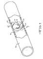
- FIG. 1is a perspective view of a prosthetic valve according to one embodiment of the invention in a body vessel.
- FIG. 2is a sectional view of the vessel and valve illustrated in FIG. 1 , taken along line 2 - 2 .
- FIG. 3is a sectional view of the vessel and valve illustrated in FIG. 1 showing the valve in an open configuration.
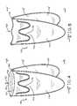
- FIG. 4is a perspective view of a prosthetic valve according to one embodiment of the invention.
- FIG. 5is a perspective view of the valve illustrated in FIG. 4 , shown in a closed configuration.
- FIG. 6is a side view of the valve illustrated in FIG. 4 .
- FIG. 7is a side view of the valve illustrated in FIG. 5 .
- FIG. 8is a perspective view of a prosthetic valve according to one embodiment of the invention.
- FIG. 9is a side view of a portion of the valve illustrated in FIG. 8 .
- FIG. 10is a perspective view of a prosthetic valve according to one embodiment of the invention.
- FIG. 11is a perspective view of a prosthetic valve according to one embodiment of the invention.
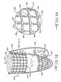
- FIG. 12is a perspective view of a prosthetic valve according to one embodiment of the invention.
- FIG. 13is a magnified view of area A highlighted in FIG. 12 .
- FIG. 14is a perspective view of a prosthetic valve according to one embodiment of the invention.
- FIG. 15is a perspective view of a valve according to one embodiment of the invention.
- FIG. 16is a sectional view of a prosthetic valve according to one embodiment of the invention disposed within a body vessel.
- the inventionprovides medical devices for implantation in a body vessel, methods of making the medical devices, and methods of treatment that utilize the medical devices.
- FIGS. 1 through 3illustrate a medical device according to a first embodiment of the invention.
- the devicecomprises a prosthetic valve 10 that is shown implanted in a body vessel 12 .
- implantedrefers to the positioning of a medical device at a location within a body, such as within a body vessel.
- implantablerefers to an ability of a medical device to be positioned at a location within a body, such as within a body vessel.
- the prosthetic valve 10comprises a valve member 14 that comprises a valve portion 15 .
- the valve member 14is positioned within a lumen of a body vessel and regulates the flow of fluid through the lumen.
- the valve portion 15is a portion of the valve member 14 and is movable between first and second positions. Movement of the valve member 15 between these positions effects the opening and closing of an opening of the prosthetic valve 10 , which controls the flow of fluid through the lumen of the vessel.
- a spacing member 16is disposed on the valve portion 15 and has a predetermined thickness 18 .
- the valve member 14can comprise a section of material, such as an extracellular matrix (ECM) material, implanted in the vessel.
- ECMextracellular matrix
- the valve portion 15can comprise any suitable moveable section of the member 14 , such as a flap formed by a slit or other discontinuity in a surface of the valve member 14 .
- FIGS. 2 and 3illustrate movement of the valve portion 15 between the first and second positions.
- fluid flow in one directionrepresented by arrow 20
- fluid flow in an opposite directionrepresented by arrow 22
- the valve portion 15can be considered in a closed configuration in response to fluid flow 20 .
- the prosthetic valve 10substantially prevents fluid from passing through the valve 10 .
- the valve portion 15can be considered in an open configuration, in which the prosthetic valve 10 allows fluid flow 22 to pass through the valve 10 .
- the valve member 14can comprise any suitable material for implantation in a body vessel.
- the valve member 14need only be able to provide the moveable valve portion 15 , and should be biocompatible or be able to be made biocompatible.
- suitable materials for the valve memberinclude natural materials, synthetic materials, and combinations thereof.
- suitable natural materialsinclude ECMs, such as small intestine submucosa (SIS), and other bioremodellable materials, such as bovine pericardium.
- ECMssmall intestine submucosa
- Other examples of ECM materials that can be used in the prosthetic valves of the inventioninclude stomach submucosa, liver basement membrane, urinary bladder submucosa, tissue mucosa, and dura mater.
- suitable synthetic materialsinclude polymeric materials, such as expanded polytetrafluoroethylene and polyurethane.
- ECMsare particularly well suited materials for use in the valve member 14 , at least because of their abilities to remodel and become incorporated into adjacent tissues. These materials can provide a scaffold onto which cellular in-growth can occur, eventually allowing the material to remodel into a structure of host cells.
- the ability of an ECM to become incorporated into the vessel wallcould allow for a prosthetic valve that does not include a support frame, such as a stent.
- FIGS. 1 through 3illustrate such a prosthetic valve.
- SISis particularly well suited for use as the valve member 14 for several reasons.
- SISis a well-characterized ECM, is able to remodel, and is durable in the presence of blood flow.
- Methods for preparing SISare disclosed in a number of United States patents, including U.S. Pat. Nos. 6,206,931, 6,358,284, and 6,666,892, each of which is hereby incorporated by reference in its entirety.
- SISis commercially available from Cook Biotech, Inc. of West Lafayette, Ind.
- the spacing member 16has a thickness 18 and is disposed on the valve portion 15 of the valve member 14 .
- the term “disposed on”refers to a spatial relationship between the spacing member 16 and the valve portion 15 , and requires only that the spacing member 16 be adjacent the valve portion 15 . The term does not require direct contact between the spacing member 16 and valve portion 15 , nor does it require attachment between these elements, although both of these spatial relationships are encompassed by the term.
- the spacing member 16protects at least a portion of the valve portion 15 from contact with the wall of the body vessel 12 as the valve portion 15 moves between the first and second positions. This protection prevents the protected portion of the valve portion 15 from contacting the wall of the body vessel 12 .
- the valve portion 15comprises an ECM or other bioremodellable material, as the spacing member 16 will prevent attachment and/or incorporation of the valve portion 15 with the wall of the body vessel 12 . If a valve portion 15 comprising an ECM is allowed prolonged and/or repeated contact with the wall of the body vessel 12 , the valve portion 15 may become fixed in an open or partially open configuration as the ECM becomes incorporated into the vessel wall.
- the inventionovercomes this concern because the spacing member 16 disposed on the valve portion 15 substantially prevents such contact between the valve portion 15 and the vessel wall. That is, the spacing member 16 protects the valve portion 15 from contact with the vessel wall. It is believed that the invention may also prevent or reduce formation of thrombus on or near the valve portion 15 .
- the spacing membercan comprise any suitable material.
- suitable materials for the spacing memberinclude natural and synthetic materials.
- suitable natural materialsinclude ECMs and other bioremodellable materials that have been treated to be biologically inert, i.e., no longer capable of remodeling.
- An example of a suitable such materialis fixed SIS.
- suitable synthetic materialsinclude polymeric materials, such as polypropylenes and polyethylenes. A combination of natural and synthetic materials can also be used.
- the spacing membercan also comprise a resorbable material.
- the term “resorbable”refers to the ability of a material to be absorbed into a tissue and/or body fluid upon contact with the tissue and/or body fluid.
- resorbable materialsare known in the art, and any suitable resorbable material can be used.
- suitable types of resorbable materialsinclude resorbable homopolymers, copolymers, or blends of resorbable polymers.
- suitable resorbable materialsinclude poly alpha hydroxy acids such as polylactic acid, polylactide, polyglycolic acid (PGA), or polyglycolide; trimethlyene carbonate; polycaprolactone; poly-beta hydroxy acids such as polyhydroxybutyrate or polyhydroxyvalerate; or other polymers such as polyphosphazines, polyorganophosphazines, polyanhydrides, polyesteramides, polyorthoesters, polyethylene oxide, polyester-ethers (e.g., polydioxanone) or polyamino acids (e.g., poly-L-glutamic acid or poly-L-lysine).
- PGApolyglycolic acid
- trimethlyene carbonatesuch as polyhydroxybutyrate
- lipophobic and/or hydrophilic materialsmay provide effective protection to a valve portion of a valve member, by providing desirable chemical properties that may facilitate the protection from prolonged contact with a vessel wall or other structural member of the valve.
- the spacing member 16is disposed only on the valve portion 15 , another portion of the valve member 14 , such as a peripheral portion, may become incorporated into the wall of the vessel 12 while the valve portion 15 does not become incorporated. This might allow implantation of a prosthetic valve in a body vessel while preventing the unintended fixing of a valve portion in an open configuration, as mentioned above.
- the spacing member 16is disposed on the valve portion 15 , but not on other portions of the valve member 14 , such as peripheral portions 25 and 27 . This configuration allows peripheral portions 25 , 27 to eventually become incorporated into the wall of the vessel 12 , while protecting the valve portion 15 from such incorporation.
- the spacing member 16is disposed entirely on the valve portion 15 , which is moveable between first and second positions, and is not disposed on other portions of the valve member 14 , such as other non-moveable portions. While this configuration may provide benefits, it is not required in all embodiments of the invention.
- the need for protection of the valve portion from repeated and/or prolonged contact with a wall of the body vesselmust be balanced against the need for cellular access to the material of the valve portion to allow the remodeling effect to occur.
- access to the material by endothelial cellsis important.
- Cellular accessallows endothelial cells to associate with the SIS and colonize the material. If this access is hindered or blocked, colonization, and ultimately remodelling, may not occur completely.
- Cellular access to the materialcan be provided in various manners, such as by employing a spacing member that comprises a porous material, and/or positioning the spacing member in a pattern and/or configuration that does not block access to the entire valve portion.
- FIGS. 4 through 7illustrate a prosthetic valve 110 according to another embodiment of the invention.
- the prosthetic valve 110comprises a valve member 114 that comprises a valve portion 115 .
- the prosthetic valve 110further comprises a second valve member 114 ′ that comprises a second valve portion 115 ′.
- Each of the valve portions 115 , 115 ′are movable between first and second positions.
- the first valve member 114comprises a first edge 117 and the second valve member 114 ′ comprises a second edge 119 .
- the first 117 and second 119 edgescooperate to define a temporary opening 126 .
- the valve members 114 , 114 ′are attached to a support frame 124 and can be described as valve leaflets.
- the support frame 124can comprise any suitable support frame with any suitable configuration for supporting the valve members 114 , 114 ′.
- a wide variety of support framesare known in the art, and any suitable support frame can be utilized.
- the support frame 124can provide a stenting function, i.e., exert a radially outward force on the interior vessel wall, but this function is not necessary.
- the medical devices of the inventioncan provide both a stenting and a valving function at a point of treatment.
- the stent artprovides numerous support frames acceptable for use in the invention, and any suitable stent can be used as the support frame.
- the support frameneed only provide the desired support member for the valve member.
- the specific support frame chosenwill depend on numerous factors, including the vessel in which the device is being implanted, the axial length of the treatment site, the number of valves desired in the support frame, the inner diameter of the vessel, the desired delivery method for placing the support frame and valve, and others. Those skilled in the art can determine an appropriate support frame based on these various factors.
- the support framecan be either self-expandable or balloon expandable.
- a balloon expandable support framemay provide an advantage to treatment sites where stenting function has particular importance.
- a self-expandable support framemay provide for relatively simple deployment at a point of treatment in a body vessel.
- the support framecan be made from a variety of materials, and need only be biocompatible, or able to be made biocompatible, and provide a stenting function, if desired.
- suitable materialsinclude, without limitation, stainless steel, nickel titanium (NiTi) alloys, e.g., nitinol, other shape memory and/or superelastic materials, polymers, and composite materials.
- Stainless steel and nitinolare particularly well-suited for use in the invention due to their biocompatibility, shapeability, and well-characterized nature.
- the support framecan also have a variety of configurations, including braided strands, helically wound strands, ring members, consecutively attached ring members, tube members, and frames cut from solid tubes.
- suitable support frames for use in medical devices according to the present inventioninclude those described in U.S. Pat. No. 6,464,720 to Boatman et al. for a RADIALLY EXPANDABLE STENT; U.S. Pat. No. 6,231,598 to Berry et al. for a RADIALLY EXPANDABLE STENT; U.S. Pat. No. 6,299,635 to Frantzen for a RADIALLY EXPANDABLE NON-AXIALLY CONTRACTING SURGICAL STENT; U.S. Pat. No.
- valve portions 115 , 115 ′respond to fluid flow in one direction, represented by arrow 122 , by moving into a first position in which edges 117 , 119 define opening 126 .
- fluid flowcan pass through the valve 110 .
- the valve portions 115 , 115 ′respond to fluid flow in the opposite direction, represented by arrow 120 , to close the opening 126 and substantially prevent fluid flow through the prosthetic valve 110 in this direction.
- the spacing member 116comprises a strand of material disposed on the valve portion 115 .
- the term “strand”refers to a structure having a thickness, and a length that is greater than its width.
- the spacing member 116can be attached to the valve portion in any suitable manner, such as with adhesives, bonding, and by weaving through a thickness of the valve portion 115 .
- a second spacing member 116 ′can be disposed on the second valve portion 115 ′.
- the spacing members 116 , 116 ′comprise strands that are arranged in a serpentine pattern.
- the spacing members 116 , 116 ′can be arranged on the valve portions 115 , 115 ′ in any suitable configuration.
- the spacing members 116 , 116 ′are arranged on the valve portions 115 , 115 ′ such that a substantial portion of each of the valve portions 115 , 115 ′ is protected from a wall of a body vessel in which the prosthetic valve 110 may be implanted.
- the spacing members 116 , 116 ′can be arranged such that space exists on the valve portions 115 , 115 ′ that is not blocked by the spacing members 116 , 116 ′. These free spaces on the valve portions 115 , 115 ′ may allow cellular access, which may facilitate any remodeling effect that may occur.
- FIGS. 8 and 9illustrate a prosthetic valve 210 according to another embodiment of the invention.
- a spacing member 216which is in the form of a strand, is disposed on the valve portion 215 and passes through a thickness 230 of the valve portion 215 .
- This arrangementresults in a portion 232 of the spacing member 216 on an opposing side of the valve portion 215 than other portions of the spacing member 216 .
- This arrangement of the spacing member 216 and valve portion 215may facilitate fabrication of the prosthetic valve 210 , and may enhance a connection between the valve portion 215 and the spacing member 216 .
- the spacing member 216could also be partially disposed in a thickness 230 of the valve portion 215 .
- the term “a thickness,” in relation to a valve member and valve portionrefers to any thickness of these components, including both entire and partial thicknesses.
- FIG. 10illustrates a prosthetic valve 310 according to another embodiment of the invention.
- the spacing member 316comprises a plurality of strands disposed on the valve portion 315 .
- the strandscan be arranged such that one strand 340 intersects another strand 342 at an intersection point 344 .
- the use of one or more intersection points 344provides an increased thickness at the points 344 , which is expected to facilitate protection of the valve member 314 .
- Intersection of one or more strands 340 , 342also allows for efficient organization of the strands 340 , 342 , which may maximize the protective effect of the spacing member 316 while still allowing cellular access to the valve member 314 for remodelling.
- the spacing member 316is disposed on the valve portion 315 , as well as on other portions of the valve member 314 .
- FIG. 11illustrates a prosthetic valve 410 according to another embodiment of the invention.
- the spacing member 416comprises a disc of material disposed on the valve portion 415 of the valve member 414 .
- the discas shown in the figure, has a substantially circular shape. It is contemplated, however, that the spacing member 416 can have any suitable size, shape, and overall configuration.
- the spacing member 416can have a square, triangular, rectangular, or elliptical cross-sectional shape.
- the spacing member 416can have a conical configuration.
- the spacing member 416can include a portion that is disposed in a thickness of the valve portion 415 . The exact size, shape, and configuration chosen for the spacing member 416 will depend on several factors, such as the extent of protection desired for the valve portion 415 and the need for cellular access to the valve portion 415 .
- a plurality of the spacing members 416can be arranged in any suitable configuration on the valve portion 415 .
- the specific arrangement chosen for a plurality of spacing members 416should balance the desire for protection of the valve portion 415 from a wall of the body vessel in which the prosthetic valve 410 will be implanted and the need for cellular access to permit remodeling to occur, as discussed above.
- FIGS. 12 and 13illustrate a prosthetic valve 510 according to another embodiment of the invention.
- the valve member 514comprises first 550 and second 552 sections.
- the first section 550can include the valve portion 515 of the valve member.
- the sections 550 , 552are distinct sections on the valve member 514 , and can abut one another, or can be separated by a third section 554 , as illustrated in the figure.
- the spacing member 516is disposed on the first section 550 .
- a second spacing member 516 ′can be disposed on the second section 552 .
- the third section 554can be substantially free of the spacing members 516 , 516 ′, which may allow movement of the valve portion 515 about a point in the third section 554 .
- This configurationis expected to allow the spacing members 516 , 516 ′ to provide protection for the first 550 and second 552 sections of the valve member 514 , while allowing the desired movement of the valve portion 515 because of the substantial absence of the spacing member 516 , 516 ′ from the third section 554 .
- the spacing member 516 in this embodimentcomprises a plurality of strands that are repeatedly passed through a thickness of the valve member 514 .
- a portion of the spacing member 516completely passes through the thickness of the valve member 514 to produce first strand portions 560 adjacent one side of the valve member 514 and second strand portions 562 adjacent an opposite side of the valve member 514 .
- the strandsintersect at intersection points 564 on one or both sides of the valve member 514 .
- the spacing member 516can pass through a partial thickness of the valve member 514 instead of passing through an entire thickness of the valve member 514 .
- the second spacing member 516 ′can also have any of these configurations, and need not have the same configuration as the first spacing member 516 .
- FIG. 14illustrates a prosthetic valve 610 according to another embodiment of the invention.
- the spacing membersurrounds a portion of the valve member. That is, the spacing member is disposed on first and second sides of a portion of the valve member.
- the spacing membercan comprise a pouch 670 that defines a cavity 672 .
- a portion of the valve member 614is disposed in the cavity 672 of the pouch 670 . This configuration of the spacing member as a pouch may facilitate fabrication of prosthetic valves according to the invention.
- FIG. 15illustrates a prosthetic valve 710 according to another embodiment of the invention.
- the spacing membercomprises an expandable support frame.
- the expandable support frameprovides support for the valve member and also provides protection for the valve portion from contact with a wall of a vessel in which the device is implanted.
- the spacing member 716comprises an expandable support frame.
- the support framehas interior and exterior surfaces. The exterior surface contacts the vessel wall, while the valve member 714 is attached to the interior surface.
- the support framecan be any suitable support frame as describe above, and need only provide for the desired attachment of the valve member 714 and the protection for the valve member 714 from contact with the vessel wall.
- the support framecan be formed of a resorbable material and can be configured to maintain the valve portion 715 in one of its two configurations until the frame is partially, substantially, or completely resorbed. This may provide a temporary protection to the valve portion 715 .
- the valve portion 715could be held in an open configuration, as illustrated in FIG. 15 , by resorbable support frame 716 .
- the support frame 716would protect the valve portion 715 from contacting the vessel wall.
- the portion of the valve member 714 on which the support frame 716 is not disposedsuch as the lower portion of the valve member 714 in the figure, would not be protected and may be able to become incorporated into the vessel wall. As the support frame 716 is resorbed, the valve portion 715 would no longer be held in the open configuration and could move freely between the open and closed configurations. Ideally, remodeling of the valve portion 715 has initiated, is substantially complete, or is complete by the time at which the support frame 716 no longer provides protection from contact with the vessel wall. Also ideally, the support frame 716 provides protection to the valve portion 715 until the non-protected portion of the valve member 714 is substantially incorporated into the vessel wall. Various properties of the spacing member 716 can be manipulated to achieve these effects, including the thickness, overall amount, resorption time, composition, and other properties.
- FIG. 16illustrates a prosthetic valve 810 according to another embodiment of the invention.
- the valve 810includes a support frame 812 and a graft member 814 that includes first 816 and second 818 valve portions.
- the valve portions 816 , 818cooperatively define a valve opening 820 that opens and closes in response to movement of the valve portions 816 , 818 .
- the support frame 812is a tubular member and the valve portions 816 , 818 are inverted into the lumen 822 of the frame 812 to form the valve opening 820 .
- Cuff portions 824 , 826 of the graft member 814are disposed on the external surface of the support frame 812 and facilitate anchoring of the prosthetic valve 810 in a body vessel 828 .
- Spacing members, 830 , 832are disposed on the inner surface 834 of the support frame 812 and are positioned substantially adjacent the ends 836 , 838 of the valve portions 816 , 818 .
- the spacing membersprotect the valve portions 816 , 818 from interaction with the support frame 812 , particularly the ends 836 , 838 of the valve portion 816 , 818 . This protection can be particularly important in tubular constructs due to movement of the valve portions within the lumen of the support frame.
- the spacing members 830 , 832can be disposed at any suitable location on the support frame 812 , including the inner and outer surfaces.
- one or more spacing membersis formed in a manner that spans one or more open cells of a support frame.
- the spacing member(s)can protect the valve portion from contacting the vessel wall through the open cells of the support frame.
- a sleeve surrounding the support framecan be used as the spacing member.
- a membercan be formed on the support frame in a manner that spans one or more open cells, such as by dipping the support frame in a polymeric material. A complete closing of one or more open cells is advantageous in these embodiments, but is not required.
- the spacing members 830 , 832can be made of any suitable material, as described above. Also, the spacing members can be formed during the fabrication of the support frame 812 or can be attached to the frame 812 in subsequent steps using any suitable technique, including laser welding, soldering, radiofrequency bonding, use of adhesives and attachment members, such as clips.
- a coating 840can be disposed on the spacing members 830 , 832 to protect the valve portions 816 , 818 from adhering to the spacing members.
- the coating 840if used, is advantageously disposed on a surface of the spacing members 830 , 832 that may contact the valve portions 816 , 818 during routine use of the prosthetic valve 810 .
- Any suitable coating that prevents or reduces adhesioncan be used, and the specific coating chosen will depend on several factors, including the material used for the valve portions 816 , 818 . Examples of suitable coatings include lubricious coatings, slip coatings, and other types of conventional coatings.
- the spacing membercan also comprise a bioactive.
- bioactiverefers to any composition that is believed to be capable of producing a biological and/or treatment effect in a host. The term includes compositions that directly produce biological effects, as well as compositions that produce, generate, or otherwise provide another composition that produces a biological effect.
- the spacing memberserves two functions. First, the spacing member provides the desired protection for the valve portion. Second, the spacing member provides a bioactive to a tissue or into a body fluid.
- bioactiveany suitable bioactive can be used in the invention, and the specific bioactive chosen will depend on the desired effect.
- suitable bioactivesinclude antithrombogenic agents, antiproliferative agents, and immunosuppressive agents.
- a wide range of other bioactivescan be used, including heparin, covalent heparin, or another thrombin inhibitor, hirudin, hirulog, argatroban, D-phenylalanyl-L-poly-L-arginyl chloromethyl ketone, or another antithrombogenic agent, or mixtures thereof; urokinase, streptokinase, a tissue plasminogen activator, or another thrombolytic agent, or mixtures thereof; a fibrinolytic agent; a vasospasm inhibitor; a calcium channel blocker, a nitrate, nitric oxide, a nitric oxide promoter or another vasodilator; Hytrin.RTM.
- an antimicrobial agent or antibioticaspirin, ticlopidine, a glycoprotein IIb/IIIa inhibitor or another inhibitor of surface glycoprotein receptors, or another antiplatelet agent; colchicine or another antimitotic, or another microtubule inhibitor, dimethyl sulfoxide (DMSO), a retinoid or another antisecretory agent; cytochalasin or another actin inhibitor; or a remodelling inhibitor; deoxyribonucleic acid, an antisense nucleotide or another agent for molecular genetic intervention; methotrexate or another antimetabolite or antiproliferative agent; tamoxifen citrate, Taxol.RTM.
- DMSOdimethyl sulfoxide
- cytochalasin or another actin inhibitoror a remodelling inhibitor
- deoxyribonucleic acidan antisense nucleotide or another agent for molecular genetic intervention
- methotrexate or another antimetabolite or antiproliferative agenttamoxifen citrate
- dexamethasonedexamethasone sodium phosphate
- dexamethasone acetate or another dexamethasone derivativeor another anti-inflammatory steroid or non-steroidal antiinflammatory agent
- cyclosporin or another immunosuppressive agenttrapidal (a PDGF antagonist), angiopeptin (a growth hormone antagonist), angiogenin, a growth factor or an anti-growth factor antibody, or another growth factor antagonist
- dopamine, bromocriptine mesylate, pergolide mesylate or another dopamine agonist.sup.60 Co (5.3 year half life), .sup.192 Ir (73.8 days), .sup.32 P (14.3 days), .sup.111 In (68 hours), .sup.90 Y (64 hours), .sup.99m Tc (6 hours) or another radiotherapeutic agent
- iodine-containing compoundsbarium-containing compounds, gold
- the bioactiveis used to inhibit restenosis, such as paclitaxel, rapamycin, and other bioactives able to inhibit restenosis of a body vessel.
- the bioactivecan comprise a bioactive capable of producing another bioactive that has a desired effect, such as a nitric oxide (NO) producing and/or releasing entity. NO may have one or more desired treatment effects, including the ability to inhibit restenosis of a body vessel.
- the spacing membercan comprise two or more bioactives.
- the bioactivecan be associated with the spacing member in any suitable manner.
- the bioactivecan be coated on a surface of the spacing member, disposed in a discrete portion of the spacing member, and dispersed throughout a portion, or the entirety, of the spacing member.
- the exact manner of associating the bioactive with the spacing memberwill depend on numerous factors, which may include the nature of the bioactive and/or spacing member, manufacturing methods, and desired treatment effect. Those skilled in the art can choose an appropriate manner of associating the bioactive with the spacing member based on these and/or other factors.
- the spacing membermay also comprise a barrier that controls release of the bioactive from the spacing member.
- the spacing membercan include a layer of the bioactive, either alone or with another material, and a barrier layer disposed on the bioactive layer.
- the bioactivecan be distributed in a barrier.
- the barrierneed only comprise a material that provides a controlled release of the bioactive from the spacing member.
- the barriercan be a polymer that controls release of the bioactive by diffusion of the bioactive through the polymer or degradation of the polymer.
- blends and layering of polymer(s)can be used to create a barrier. Examples of suitable arrangements of barriers are in U.S. Pat. No. 6,299,604 to Ragheb for a COATED IMPLANTABLE MEDICAL DEVICE, which is hereby incorporated by reference in its entirety.
- methods according to the inventioncomprise methods of making prosthetic valves.
- One method according to the inventioncomprises providing a valve member comprising a valve portion that is moveable between first and second positions and disposing a spacing member on the valve portion.
- the disposing stepcan be accomplished in any suitable manner, which can include adhering, such as by using adhesives, bonding, and weaving.
- the methodcan comprise disposing a portion of the spacing member on the valve portion and passing a portion of the spacing member through a thickness of the valve portion.
- the thicknesscan be an entire or a partial thickness.
- the spacing membercan be repeatedly passed through a thickness of the valve portion.
- the spacing member used in the methods of making a medical device according to the inventioncan comprise any suitable spacing member.
- suitable spacing membersinclude those described herein, such as strands and pouches.
- a pouch defining a cavityis provided, and a portion of a valve member is disposed in the cavity.
- the spacing membercan comprise a resorbable support frame.
- a method of making a medical device according to the inventioncomprises providing a resorbable support frame, providing a valve member, and attaching the valve member to the support frame so that the valve member comprises a valve portion moveable between first and second positions and so that the support frame temporarily maintains the valve member in the first position.
- the temporary maintenance of the valve member in the first positioncan endure until resorption of the support frame is initiated, is partially complete, is substantially complete, or is complete.
- the inventionalso provides methods of treatment.
- Methods of treatment according to the inventioninclude implanting any medical device according to the invention in a body vessel at a point of treatment.
- One method according to the inventioncomprises providing a prosthetic valve comprising a valve member comprising a valve portion moveable between first and second positions, and a support frame attached to the valve portion and adapted to maintain the valve portion in the first position for a period of time.
- Another step of the methodcomprises implanting the prosthetic valve in a body vessel.
- the implanting stepcan be accomplished by any suitable technique, including surgical implantation and percutaneous delivery to a point of treatment in the body vessel. The technique chosen will depend on several factors, including the configuration of the prosthetic valve.
Landscapes
- Health & Medical Sciences (AREA)
- Cardiology (AREA)
- Engineering & Computer Science (AREA)
- Biomedical Technology (AREA)
- Heart & Thoracic Surgery (AREA)
- Transplantation (AREA)
- Oral & Maxillofacial Surgery (AREA)
- Vascular Medicine (AREA)
- Life Sciences & Earth Sciences (AREA)
- Animal Behavior & Ethology (AREA)
- General Health & Medical Sciences (AREA)
- Public Health (AREA)
- Veterinary Medicine (AREA)
- Prostheses (AREA)
Abstract
Description
Claims (17)
Priority Applications (2)
| Application Number | Priority Date | Filing Date | Title |
|---|---|---|---|
| US11/061,352US7955375B2 (en) | 2004-02-20 | 2005-02-18 | Prosthetic valve with spacing member |
| US13/118,724US8317853B2 (en) | 2004-02-20 | 2011-05-31 | Prosthetic valve with external support frame |
Applications Claiming Priority (2)
| Application Number | Priority Date | Filing Date | Title |
|---|---|---|---|
| US54653204P | 2004-02-20 | 2004-02-20 | |
| US11/061,352US7955375B2 (en) | 2004-02-20 | 2005-02-18 | Prosthetic valve with spacing member |
Related Child Applications (1)
| Application Number | Title | Priority Date | Filing Date |
|---|---|---|---|
| US13/118,724ContinuationUS8317853B2 (en) | 2004-02-20 | 2011-05-31 | Prosthetic valve with external support frame |
Publications (2)
| Publication Number | Publication Date |
|---|---|
| US20050187614A1 US20050187614A1 (en) | 2005-08-25 |
| US7955375B2true US7955375B2 (en) | 2011-06-07 |
Family
ID=34910784
Family Applications (2)
| Application Number | Title | Priority Date | Filing Date |
|---|---|---|---|
| US11/061,352Active2028-06-28US7955375B2 (en) | 2004-02-20 | 2005-02-18 | Prosthetic valve with spacing member |
| US13/118,724Expired - LifetimeUS8317853B2 (en) | 2004-02-20 | 2011-05-31 | Prosthetic valve with external support frame |
Family Applications After (1)
| Application Number | Title | Priority Date | Filing Date |
|---|---|---|---|
| US13/118,724Expired - LifetimeUS8317853B2 (en) | 2004-02-20 | 2011-05-31 | Prosthetic valve with external support frame |
Country Status (3)
| Country | Link |
|---|---|
| US (2) | US7955375B2 (en) |
| EP (1) | EP1727499B1 (en) |
| WO (1) | WO2005082289A1 (en) |
Cited By (31)
| Publication number | Priority date | Publication date | Assignee | Title |
|---|---|---|---|---|
| US20110137410A1 (en)* | 2009-12-08 | 2011-06-09 | Hacohen Gil | Foldable hinged prosthetic heart valve |
| US8852272B2 (en) | 2011-08-05 | 2014-10-07 | Mitraltech Ltd. | Techniques for percutaneous mitral valve replacement and sealing |
| US8992604B2 (en) | 2010-07-21 | 2015-03-31 | Mitraltech Ltd. | Techniques for percutaneous mitral valve replacement and sealing |
| US9017399B2 (en) | 2010-07-21 | 2015-04-28 | Mitraltech Ltd. | Techniques for percutaneous mitral valve replacement and sealing |
| US9510934B2 (en) | 2012-07-20 | 2016-12-06 | Cook Medical Technologies Llc | Implantable medical device having a sleeve |
| US9610161B2 (en)* | 2000-09-20 | 2017-04-04 | Mvrx, Inc. | Devices, systems, and methods for supplementing, repairing or replacing a native heart valve leaflet |
| US9681952B2 (en) | 2013-01-24 | 2017-06-20 | Mitraltech Ltd. | Anchoring of prosthetic valve supports |
| US9763657B2 (en) | 2010-07-21 | 2017-09-19 | Mitraltech Ltd. | Techniques for percutaneous mitral valve replacement and sealing |
| USD800908S1 (en) | 2016-08-10 | 2017-10-24 | Mitraltech Ltd. | Prosthetic valve element |
| US9974651B2 (en) | 2015-02-05 | 2018-05-22 | Mitral Tech Ltd. | Prosthetic valve with axially-sliding frames |
| USD841813S1 (en) | 2017-08-03 | 2019-02-26 | Cardiovalve Ltd. | Prosthetic heart valve element |
| US10245143B2 (en) | 2011-08-05 | 2019-04-02 | Cardiovalve Ltd. | Techniques for percutaneous mitral valve replacement and sealing |
| US10376361B2 (en) | 2011-08-05 | 2019-08-13 | Cardiovalve Ltd. | Techniques for percutaneous mitral valve replacement and sealing |
| US10390952B2 (en) | 2015-02-05 | 2019-08-27 | Cardiovalve Ltd. | Prosthetic valve with flexible tissue anchor portions |
| US10492908B2 (en) | 2014-07-30 | 2019-12-03 | Cardiovalve Ltd. | Anchoring of a prosthetic valve |
| US10531866B2 (en) | 2016-02-16 | 2020-01-14 | Cardiovalve Ltd. | Techniques for providing a replacement valve and transseptal communication |
| US10575948B2 (en) | 2017-08-03 | 2020-03-03 | Cardiovalve Ltd. | Prosthetic heart valve |
| US10856975B2 (en) | 2016-08-10 | 2020-12-08 | Cardiovalve Ltd. | Prosthetic valve with concentric frames |
| US10888421B2 (en) | 2017-09-19 | 2021-01-12 | Cardiovalve Ltd. | Prosthetic heart valve with pouch |
| US10940167B2 (en) | 2012-02-10 | 2021-03-09 | Cvdevices, Llc | Methods and uses of biological tissues for various stent and other medical applications |
| US11109964B2 (en) | 2010-03-10 | 2021-09-07 | Cardiovalve Ltd. | Axially-shortening prosthetic valve |
| US11246704B2 (en) | 2017-08-03 | 2022-02-15 | Cardiovalve Ltd. | Prosthetic heart valve |
| US11291546B2 (en) | 2011-08-05 | 2022-04-05 | Cardiovalve Ltd. | Leaflet clip with collars |
| US11382746B2 (en) | 2017-12-13 | 2022-07-12 | Cardiovalve Ltd. | Prosthetic valve and delivery tool therefor |
| US11406495B2 (en) | 2013-02-11 | 2022-08-09 | Cook Medical Technologies Llc | Expandable support frame and medical device |
| US11633277B2 (en) | 2018-01-10 | 2023-04-25 | Cardiovalve Ltd. | Temperature-control during crimping of an implant |
| US11653910B2 (en) | 2010-07-21 | 2023-05-23 | Cardiovalve Ltd. | Helical anchor implantation |
| US11793633B2 (en) | 2017-08-03 | 2023-10-24 | Cardiovalve Ltd. | Prosthetic heart valve |
| US12029646B2 (en) | 2017-08-03 | 2024-07-09 | Cardiovalve Ltd. | Prosthetic heart valve |
| US12053379B2 (en) | 2016-08-01 | 2024-08-06 | Cardiovalve Ltd. | Minimally-invasive delivery systems |
| US12357459B2 (en) | 2020-12-03 | 2025-07-15 | Cardiovalve Ltd. | Transluminal delivery system |
Families Citing this family (60)
| Publication number | Priority date | Publication date | Assignee | Title |
|---|---|---|---|---|
| US6440164B1 (en) | 1999-10-21 | 2002-08-27 | Scimed Life Systems, Inc. | Implantable prosthetic valve |
| US6602286B1 (en) | 2000-10-26 | 2003-08-05 | Ernst Peter Strecker | Implantable valve system |
| US6752828B2 (en) | 2002-04-03 | 2004-06-22 | Scimed Life Systems, Inc. | Artificial valve |
| AU2003285943B2 (en) | 2002-10-24 | 2008-08-21 | Boston Scientific Limited | Venous valve apparatus and method |
| US6945957B2 (en) | 2002-12-30 | 2005-09-20 | Scimed Life Systems, Inc. | Valve treatment catheter and methods |
| US7854761B2 (en) | 2003-12-19 | 2010-12-21 | Boston Scientific Scimed, Inc. | Methods for venous valve replacement with a catheter |
| US8128681B2 (en) | 2003-12-19 | 2012-03-06 | Boston Scientific Scimed, Inc. | Venous valve apparatus, system, and method |
| US8349001B2 (en)* | 2004-04-07 | 2013-01-08 | Medtronic, Inc. | Pharmacological delivery implement for use with cardiac repair devices |
| US7566343B2 (en) | 2004-09-02 | 2009-07-28 | Boston Scientific Scimed, Inc. | Cardiac valve, system, and method |
| CA2583938A1 (en)* | 2004-10-06 | 2006-04-20 | Cook Incorporated | Medical device with bioactive agent |
| US7854755B2 (en) | 2005-02-01 | 2010-12-21 | Boston Scientific Scimed, Inc. | Vascular catheter, system, and method |
| US20060173490A1 (en) | 2005-02-01 | 2006-08-03 | Boston Scientific Scimed, Inc. | Filter system and method |
| US7878966B2 (en) | 2005-02-04 | 2011-02-01 | Boston Scientific Scimed, Inc. | Ventricular assist and support device |
| US7670368B2 (en) | 2005-02-07 | 2010-03-02 | Boston Scientific Scimed, Inc. | Venous valve apparatus, system, and method |
| US7780722B2 (en) | 2005-02-07 | 2010-08-24 | Boston Scientific Scimed, Inc. | Venous valve apparatus, system, and method |
| US7867274B2 (en) | 2005-02-23 | 2011-01-11 | Boston Scientific Scimed, Inc. | Valve apparatus, system and method |
| US7722666B2 (en) | 2005-04-15 | 2010-05-25 | Boston Scientific Scimed, Inc. | Valve apparatus, system and method |
| US8012198B2 (en) | 2005-06-10 | 2011-09-06 | Boston Scientific Scimed, Inc. | Venous valve, system, and method |
| US7569071B2 (en) | 2005-09-21 | 2009-08-04 | Boston Scientific Scimed, Inc. | Venous valve, system, and method with sinus pocket |
| US7799038B2 (en) | 2006-01-20 | 2010-09-21 | Boston Scientific Scimed, Inc. | Translumenal apparatus, system, and method |
| US7811316B2 (en) | 2006-05-25 | 2010-10-12 | Deep Vein Medical, Inc. | Device for regulating blood flow |
| US8092517B2 (en)* | 2006-05-25 | 2012-01-10 | Deep Vein Medical, Inc. | Device for regulating blood flow |
| US20080281249A1 (en)* | 2006-10-30 | 2008-11-13 | Michael Gertner | Valves and Conduits for Vascular Access |
| WO2008091493A1 (en) | 2007-01-08 | 2008-07-31 | California Institute Of Technology | In-situ formation of a valve |
| US7678144B2 (en)* | 2007-01-29 | 2010-03-16 | Cook Incorporated | Prosthetic valve with slanted leaflet design |
| US8303649B2 (en)* | 2007-01-29 | 2012-11-06 | Cook Medical Technologies Llc | Artificial venous valve with discrete shaping members |
| US7967853B2 (en) | 2007-02-05 | 2011-06-28 | Boston Scientific Scimed, Inc. | Percutaneous valve, system and method |
| US8403979B2 (en)* | 2007-05-17 | 2013-03-26 | Cook Medical Technologies Llc | Monocuspid prosthetic valve having a partial sinus |
| US8828079B2 (en) | 2007-07-26 | 2014-09-09 | Boston Scientific Scimed, Inc. | Circulatory valve, system and method |
| US7892276B2 (en) | 2007-12-21 | 2011-02-22 | Boston Scientific Scimed, Inc. | Valve with delayed leaflet deployment |
| US8100962B2 (en) | 2008-01-08 | 2012-01-24 | Cook Medical Technologies Llc | Flow-deflecting prosthesis for treating venous disease |
| WO2009094373A1 (en)* | 2008-01-22 | 2009-07-30 | Cook Incorporated | Valve frame |
| US8109990B2 (en)* | 2009-02-24 | 2012-02-07 | Cook Medical Technologies Llc | Low profile support frame and related intraluminal medical devices |
| US8579964B2 (en) | 2010-05-05 | 2013-11-12 | Neovasc Inc. | Transcatheter mitral valve prosthesis |
| US20130245534A1 (en)* | 2011-01-11 | 2013-09-19 | Amsel Medical Corporation | Injectable valve and other flow control elements |
| US9554897B2 (en) | 2011-04-28 | 2017-01-31 | Neovasc Tiara Inc. | Methods and apparatus for engaging a valve prosthesis with tissue |
| US9308087B2 (en) | 2011-04-28 | 2016-04-12 | Neovasc Tiara Inc. | Sequentially deployed transcatheter mitral valve prosthesis |
| US9668859B2 (en) | 2011-08-05 | 2017-06-06 | California Institute Of Technology | Percutaneous heart valve delivery systems |
| US9345573B2 (en) | 2012-05-30 | 2016-05-24 | Neovasc Tiara Inc. | Methods and apparatus for loading a prosthesis onto a delivery system |
| WO2013190344A1 (en)* | 2012-06-22 | 2013-12-27 | Pierre Squara | Heart valve prostheses |
| WO2014144247A1 (en) | 2013-03-15 | 2014-09-18 | Arash Kheradvar | Handle mechanism and functionality for repositioning and retrieval of transcatheter heart valves |
| US9572665B2 (en) | 2013-04-04 | 2017-02-21 | Neovasc Tiara Inc. | Methods and apparatus for delivering a prosthetic valve to a beating heart |
| US10010399B2 (en) | 2014-08-29 | 2018-07-03 | Cook Medical Technologies Llc | Low profile intraluminal filters |
| US10143544B2 (en) | 2014-08-29 | 2018-12-04 | Cook Medical Technologies Llc | Low profile intraluminal medical devices |
| WO2016098877A1 (en)* | 2014-12-19 | 2016-06-23 | 国立研究開発法人国立循環器病研究センター | Substrate for forming artificial valve and artificial valve |
| CA3007660A1 (en) | 2015-12-15 | 2017-06-22 | Neovasc Tiara Inc. | Transseptal delivery system |
| US9968447B2 (en) | 2016-01-22 | 2018-05-15 | Medtronic Vascular, Inc. | Bioprosthetic tissue for use as a prosthetic valve leaflet and method of preparing |
| US10433952B2 (en) | 2016-01-29 | 2019-10-08 | Neovasc Tiara Inc. | Prosthetic valve for avoiding obstruction of outflow |
| CA3042588A1 (en) | 2016-11-21 | 2018-05-24 | Neovasc Tiara Inc. | Methods and systems for rapid retraction of a transcatheter heart valve delivery system |
| US10368991B2 (en)* | 2017-02-06 | 2019-08-06 | C. R. Bard, Inc. | Device and associated percutaneous minimally invasive method for creating a venous valve |
| CA3073834A1 (en) | 2017-08-25 | 2019-02-28 | Neovasc Tiara Inc. | Sequentially deployed transcatheter mitral valve prosthesis |
| EP4238539A3 (en)* | 2017-10-25 | 2023-10-18 | Boston Scientific Scimed, Inc. | Stent with atraumatic spacer |
| CN113271890B (en) | 2018-11-08 | 2024-08-30 | 内奥瓦斯克迪亚拉公司 | Ventricular deployment of transcatheter mitral valve prosthesis |
| CA3132873A1 (en) | 2019-03-08 | 2020-09-17 | Neovasc Tiara Inc. | Retrievable prosthesis delivery system |
| CA3135753C (en) | 2019-04-01 | 2023-10-24 | Neovasc Tiara Inc. | Controllably deployable prosthetic valve |
| US11491006B2 (en) | 2019-04-10 | 2022-11-08 | Neovasc Tiara Inc. | Prosthetic valve with natural blood flow |
| US11779742B2 (en) | 2019-05-20 | 2023-10-10 | Neovasc Tiara Inc. | Introducer with hemostasis mechanism |
| JP7520897B2 (en) | 2019-06-20 | 2024-07-23 | ニオバスク ティアラ インコーポレイテッド | Thin prosthetic mitral valve |
| CN115361991A (en) | 2020-01-30 | 2022-11-18 | 兰巴姆医疗技术有限公司 | Catheter prosthesis |
| US12349893B2 (en) | 2021-02-25 | 2025-07-08 | Cook Medical Technologies Llc | Implantable tissue anchors, kits that include a tissue anchor, and related methods of treatment |
Citations (19)
| Publication number | Priority date | Publication date | Assignee | Title |
|---|---|---|---|---|
| US4222126A (en)* | 1978-12-14 | 1980-09-16 | The United States Of America As Represented By The Secretary Of The Department Of Health, Education & Welfare | Unitized three leaflet heart valve |
| US4580568A (en) | 1984-10-01 | 1986-04-08 | Cook, Incorporated | Percutaneous endovascular stent and method for insertion thereof |
| US5314473A (en)* | 1989-07-20 | 1994-05-24 | Godin Norman J | Prosthesis for preventing gastric reflux into the esophagus |
| US6206931B1 (en) | 1996-08-23 | 2001-03-27 | Cook Incorporated | Graft prosthesis materials |
| US6231598B1 (en) | 1997-09-24 | 2001-05-15 | Med Institute, Inc. | Radially expandable stent |
| WO2001056500A2 (en) | 2000-02-03 | 2001-08-09 | Cook Incorporated | Implantable vascular device |
| US6299604B1 (en) | 1998-08-20 | 2001-10-09 | Cook Incorporated | Coated implantable medical device |
| US6299635B1 (en) | 1997-09-29 | 2001-10-09 | Cook Incorporated | Radially expandable non-axially contracting surgical stent |
| US20010039450A1 (en) | 1999-06-02 | 2001-11-08 | Dusan Pavcnik | Implantable vascular device |
| US20010041928A1 (en)* | 2000-05-04 | 2001-11-15 | Oregon Health Services University | Endovascular stent graft |
| US6358284B1 (en) | 1996-12-10 | 2002-03-19 | Med Institute, Inc. | Tubular grafts from purified submucosa |
| WO2002024119A1 (en)* | 2000-09-21 | 2002-03-28 | St. Jude Medical, Inc. | Valved prostheses with reinforced polymer leaflets |
| US6458153B1 (en) | 1999-12-31 | 2002-10-01 | Abps Venture One, Ltd. | Endoluminal cardiac and venous valve prostheses and methods of manufacture and delivery thereof |
| US6494909B2 (en) | 2000-12-01 | 2002-12-17 | Prodesco, Inc. | Endovascular valve |
| US6508833B2 (en) | 1998-06-02 | 2003-01-21 | Cook Incorporated | Multiple-sided intraluminal medical device |
| US6666892B2 (en) | 1996-08-23 | 2003-12-23 | Cook Biotech Incorporated | Multi-formed collagenous biomaterial medical device |
| US20040044407A1 (en)* | 2000-07-11 | 2004-03-04 | Alessandro Verona | Biomaterial including animal corneal tissue |
| US20040117004A1 (en)* | 2002-05-16 | 2004-06-17 | Osborne Thomas A. | Stent and method of forming a stent with integral barbs |
| WO2004080352A1 (en) | 2003-03-12 | 2004-09-23 | Cook Incorporated | Prosthetic valve that permits retrograde flow |
- 2005
- 2005-02-18WOPCT/US2005/005304patent/WO2005082289A1/enactiveSearch and Examination
- 2005-02-18EPEP05713823Apatent/EP1727499B1/ennot_activeExpired - Lifetime
- 2005-02-18USUS11/061,352patent/US7955375B2/enactiveActive
- 2011
- 2011-05-31USUS13/118,724patent/US8317853B2/ennot_activeExpired - Lifetime
Patent Citations (22)
| Publication number | Priority date | Publication date | Assignee | Title |
|---|---|---|---|---|
| US4222126A (en)* | 1978-12-14 | 1980-09-16 | The United States Of America As Represented By The Secretary Of The Department Of Health, Education & Welfare | Unitized three leaflet heart valve |
| US4580568A (en) | 1984-10-01 | 1986-04-08 | Cook, Incorporated | Percutaneous endovascular stent and method for insertion thereof |
| US5314473A (en)* | 1989-07-20 | 1994-05-24 | Godin Norman J | Prosthesis for preventing gastric reflux into the esophagus |
| US6206931B1 (en) | 1996-08-23 | 2001-03-27 | Cook Incorporated | Graft prosthesis materials |
| US6666892B2 (en) | 1996-08-23 | 2003-12-23 | Cook Biotech Incorporated | Multi-formed collagenous biomaterial medical device |
| US6358284B1 (en) | 1996-12-10 | 2002-03-19 | Med Institute, Inc. | Tubular grafts from purified submucosa |
| US6231598B1 (en) | 1997-09-24 | 2001-05-15 | Med Institute, Inc. | Radially expandable stent |
| US6464720B2 (en) | 1997-09-24 | 2002-10-15 | Cook Incorporated | Radially expandable stent |
| US6299635B1 (en) | 1997-09-29 | 2001-10-09 | Cook Incorporated | Radially expandable non-axially contracting surgical stent |
| US6508833B2 (en) | 1998-06-02 | 2003-01-21 | Cook Incorporated | Multiple-sided intraluminal medical device |
| US6299604B1 (en) | 1998-08-20 | 2001-10-09 | Cook Incorporated | Coated implantable medical device |
| US20010039450A1 (en) | 1999-06-02 | 2001-11-08 | Dusan Pavcnik | Implantable vascular device |
| US6458153B1 (en) | 1999-12-31 | 2002-10-01 | Abps Venture One, Ltd. | Endoluminal cardiac and venous valve prostheses and methods of manufacture and delivery thereof |
| US20040106976A1 (en) | 1999-12-31 | 2004-06-03 | Bailey Steven R. | Endoluminal cardiac and venous valve prostheses and methods of manufacture and delivery thereof |
| WO2001056500A2 (en) | 2000-02-03 | 2001-08-09 | Cook Incorporated | Implantable vascular device |
| US20010041928A1 (en)* | 2000-05-04 | 2001-11-15 | Oregon Health Services University | Endovascular stent graft |
| US20040044407A1 (en)* | 2000-07-11 | 2004-03-04 | Alessandro Verona | Biomaterial including animal corneal tissue |
| WO2002024119A1 (en)* | 2000-09-21 | 2002-03-28 | St. Jude Medical, Inc. | Valved prostheses with reinforced polymer leaflets |
| US6494909B2 (en) | 2000-12-01 | 2002-12-17 | Prodesco, Inc. | Endovascular valve |
| US20040117004A1 (en)* | 2002-05-16 | 2004-06-17 | Osborne Thomas A. | Stent and method of forming a stent with integral barbs |
| WO2004080352A1 (en) | 2003-03-12 | 2004-09-23 | Cook Incorporated | Prosthetic valve that permits retrograde flow |
| US20040225352A1 (en)* | 2003-03-12 | 2004-11-11 | Osborne Thomas A. | Prosthetic valve that permits retrograde flow |
Cited By (101)
| Publication number | Priority date | Publication date | Assignee | Title |
|---|---|---|---|---|
| US9610161B2 (en)* | 2000-09-20 | 2017-04-04 | Mvrx, Inc. | Devices, systems, and methods for supplementing, repairing or replacing a native heart valve leaflet |
| US8870950B2 (en) | 2009-12-08 | 2014-10-28 | Mitral Tech Ltd. | Rotation-based anchoring of an implant |
| US11141268B2 (en) | 2009-12-08 | 2021-10-12 | Cardiovalve Ltd. | Prosthetic heart valve with upper and lower skirts |
| US11351026B2 (en) | 2009-12-08 | 2022-06-07 | Cardiovalve Ltd. | Rotation-based anchoring of an implant |
| US10660751B2 (en) | 2009-12-08 | 2020-05-26 | Cardiovalve Ltd. | Prosthetic heart valve with upper skirt |
| US10610359B2 (en) | 2009-12-08 | 2020-04-07 | Cardiovalve Ltd. | Folding ring prosthetic heart valve |
| US10548726B2 (en) | 2009-12-08 | 2020-02-04 | Cardiovalve Ltd. | Rotation-based anchoring of an implant |
| US20110137410A1 (en)* | 2009-12-08 | 2011-06-09 | Hacohen Gil | Foldable hinged prosthetic heart valve |
| US11839541B2 (en) | 2009-12-08 | 2023-12-12 | Cardiovalve Ltd. | Prosthetic heart valve with upper skirt |
| US10231831B2 (en) | 2009-12-08 | 2019-03-19 | Cardiovalve Ltd. | Folding ring implant for heart valve |
| US12167963B2 (en) | 2010-03-10 | 2024-12-17 | Cardiovalve Ltd. | Method for use at a heart valve |
| US11109964B2 (en) | 2010-03-10 | 2021-09-07 | Cardiovalve Ltd. | Axially-shortening prosthetic valve |
| US12310575B2 (en) | 2010-07-21 | 2025-05-27 | Cardiovalve Ltd. | Helical anchor implantation |
| US9763657B2 (en) | 2010-07-21 | 2017-09-19 | Mitraltech Ltd. | Techniques for percutaneous mitral valve replacement and sealing |
| US8992604B2 (en) | 2010-07-21 | 2015-03-31 | Mitraltech Ltd. | Techniques for percutaneous mitral valve replacement and sealing |
| US9017399B2 (en) | 2010-07-21 | 2015-04-28 | Mitraltech Ltd. | Techniques for percutaneous mitral valve replacement and sealing |
| US9132009B2 (en) | 2010-07-21 | 2015-09-15 | Mitraltech Ltd. | Guide wires with commissural anchors to advance a prosthetic valve |
| US11426155B2 (en) | 2010-07-21 | 2022-08-30 | Cardiovalve Ltd. | Helical anchor implantation |
| US11969163B2 (en) | 2010-07-21 | 2024-04-30 | Cardiovalve Ltd. | Valve prosthesis configured for deployment in annular spacer |
| US10925595B2 (en) | 2010-07-21 | 2021-02-23 | Cardiovalve Ltd. | Valve prosthesis configured for deployment in annular spacer |
| US10531872B2 (en) | 2010-07-21 | 2020-01-14 | Cardiovalve Ltd. | Valve prosthesis configured for deployment in annular spacer |
| US11653910B2 (en) | 2010-07-21 | 2023-05-23 | Cardiovalve Ltd. | Helical anchor implantation |
| US10512456B2 (en) | 2010-07-21 | 2019-12-24 | Cardiovalve Ltd. | Techniques for percutaneous mitral valve replacement and sealing |
| US11517429B2 (en) | 2011-08-05 | 2022-12-06 | Cardiovalve Ltd. | Apparatus for use at a heart valve |
| US12396848B2 (en) | 2011-08-05 | 2025-08-26 | Cardiovalve Ltd. | Method for use at a heart valve |
| US8852272B2 (en) | 2011-08-05 | 2014-10-07 | Mitraltech Ltd. | Techniques for percutaneous mitral valve replacement and sealing |
| US11690712B2 (en) | 2011-08-05 | 2023-07-04 | Cardiovalve Ltd. | Clip-secured implant for heart valve |
| US11291546B2 (en) | 2011-08-05 | 2022-04-05 | Cardiovalve Ltd. | Leaflet clip with collars |
| US11864995B2 (en) | 2011-08-05 | 2024-01-09 | Cardiovalve Ltd. | Implant for heart valve |
| US11517436B2 (en) | 2011-08-05 | 2022-12-06 | Cardiovalve Ltd. | Implant for heart valve |
| US11951005B2 (en) | 2011-08-05 | 2024-04-09 | Cardiovalve Ltd. | Implant for heart valve |
| US10376361B2 (en) | 2011-08-05 | 2019-08-13 | Cardiovalve Ltd. | Techniques for percutaneous mitral valve replacement and sealing |
| US11291545B2 (en) | 2011-08-05 | 2022-04-05 | Cardiovalve Ltd. | Implant for heart valve |
| US10245143B2 (en) | 2011-08-05 | 2019-04-02 | Cardiovalve Ltd. | Techniques for percutaneous mitral valve replacement and sealing |
| US9387078B2 (en) | 2011-08-05 | 2016-07-12 | Mitraltech Ltd. | Percutaneous mitral valve replacement and sealing |
| US11291547B2 (en) | 2011-08-05 | 2022-04-05 | Cardiovalve Ltd. | Leaflet clip with collars |
| US11344410B2 (en) | 2011-08-05 | 2022-05-31 | Cardiovalve Ltd. | Implant for heart valve |
| US10702385B2 (en) | 2011-08-05 | 2020-07-07 | Cardiovalve Ltd. | Implant for heart valve |
| US11369469B2 (en) | 2011-08-05 | 2022-06-28 | Cardiovalve Ltd. | Method for use at a heart valve |
| US10695173B2 (en) | 2011-08-05 | 2020-06-30 | Cardiovalve Ltd. | Techniques for percutaneous mitral valve replacement and sealing |
| US10226341B2 (en) | 2011-08-05 | 2019-03-12 | Cardiovalve Ltd. | Implant for heart valve |
| US10940167B2 (en) | 2012-02-10 | 2021-03-09 | Cvdevices, Llc | Methods and uses of biological tissues for various stent and other medical applications |
| US9510934B2 (en) | 2012-07-20 | 2016-12-06 | Cook Medical Technologies Llc | Implantable medical device having a sleeve |
| US9681952B2 (en) | 2013-01-24 | 2017-06-20 | Mitraltech Ltd. | Anchoring of prosthetic valve supports |
| US10631982B2 (en) | 2013-01-24 | 2020-04-28 | Cardiovale Ltd. | Prosthetic valve and upstream support therefor |
| US10835377B2 (en) | 2013-01-24 | 2020-11-17 | Cardiovalve Ltd. | Rolled prosthetic valve support |
| US11844691B2 (en) | 2013-01-24 | 2023-12-19 | Cardiovalve Ltd. | Partially-covered prosthetic valves |
| US11135059B2 (en) | 2013-01-24 | 2021-10-05 | Cardiovalve Ltd. | Prosthetic valve and upstream support therefor |
| US11406495B2 (en) | 2013-02-11 | 2022-08-09 | Cook Medical Technologies Llc | Expandable support frame and medical device |
| US12053380B2 (en) | 2014-07-30 | 2024-08-06 | Cardiovalve Ltd. | Anchoring of a prosthetic valve |
| US10492908B2 (en) | 2014-07-30 | 2019-12-03 | Cardiovalve Ltd. | Anchoring of a prosthetic valve |
| US10463487B2 (en) | 2015-02-05 | 2019-11-05 | Cardiovalve Ltd. | Prosthetic valve delivery system with independently-movable capsule portions |
| US10507105B2 (en) | 2015-02-05 | 2019-12-17 | Cardiovalve Ltd. | Prosthetic valve with tissue anchors free from lateral interconnections |
| US10888422B2 (en) | 2015-02-05 | 2021-01-12 | Cardiovalve Ltd. | Prosthetic valve with flexible tissue anchor portions |
| US10973636B2 (en) | 2015-02-05 | 2021-04-13 | Cardiovalve Ltd. | Prosthetic valve with tissue anchors free from lateral interconnections |
| US12396851B2 (en) | 2015-02-05 | 2025-08-26 | Cardiovalve Ltd. | Prosthetic valve with arms and flanges |
| US10864078B2 (en) | 2015-02-05 | 2020-12-15 | Cardiovalve Ltd. | Prosthetic valve with separably-deployable valve body and tissue anchors |
| US9974651B2 (en) | 2015-02-05 | 2018-05-22 | Mitral Tech Ltd. | Prosthetic valve with axially-sliding frames |
| US10357360B2 (en) | 2015-02-05 | 2019-07-23 | Cardiovalve Ltd. | Prosthetic valve with aligned inner and outer frames |
| US10849748B2 (en) | 2015-02-05 | 2020-12-01 | Cardiovalve Ltd. | Prosthetic valve delivery system with independently-movable capsule portions |
| US10758344B2 (en) | 2015-02-05 | 2020-09-01 | Cardiovalve Ltd. | Prosthetic valve with angularly offset frames |
| US10736742B2 (en) | 2015-02-05 | 2020-08-11 | Cardiovalve Ltd. | Prosthetic valve with atrial arms |
| US10390952B2 (en) | 2015-02-05 | 2019-08-27 | Cardiovalve Ltd. | Prosthetic valve with flexible tissue anchor portions |
| US10722360B2 (en) | 2015-02-05 | 2020-07-28 | Cardiovalve Ltd. | Prosthetic valve with radially-deflectable tissue anchors |
| US10695177B2 (en) | 2015-02-05 | 2020-06-30 | Cardiovalve Ltd. | Prosthetic valve with aligned inner and outer frames |
| US10682227B2 (en) | 2015-02-05 | 2020-06-16 | Cardiovalve Ltd. | Prosthetic valve with pivoting tissue anchor portions |
| US10426610B2 (en) | 2015-02-05 | 2019-10-01 | Cardiovalve Ltd. | Prosthetic valve with radially-deflectable tissue anchors |
| US10667908B2 (en) | 2015-02-05 | 2020-06-02 | Cardiovalve Ltd. | Prosthetic valve with S-shaped tissue anchors |
| US10449047B2 (en) | 2015-02-05 | 2019-10-22 | Cardiovalve Ltd. | Prosthetic heart valve with compressible frames |
| US10463488B2 (en) | 2015-02-05 | 2019-11-05 | Cardiovalve Ltd. | Prosthetic valve with separably-deployable valve body and tissue anchors |
| US11801135B2 (en) | 2015-02-05 | 2023-10-31 | Cardiovalve Ltd. | Techniques for deployment of a prosthetic valve |
| US11534298B2 (en) | 2015-02-05 | 2022-12-27 | Cardiovalve Ltd. | Prosthetic valve with s-shaped tissue anchors |
| US11793638B2 (en) | 2015-02-05 | 2023-10-24 | Cardiovalve Ltd. | Prosthetic valve with pivoting tissue anchor portions |
| US11793635B2 (en) | 2015-02-05 | 2023-10-24 | Cardiovalve Ltd. | Prosthetic valve with angularly offset frames |
| US10524903B2 (en) | 2015-02-05 | 2020-01-07 | Cardiovalve Ltd. | Prosthetic valve with aligned inner and outer frames |
| US11672658B2 (en) | 2015-02-05 | 2023-06-13 | Cardiovalve Ltd. | Prosthetic valve with aligned inner and outer frames |
| US10918481B2 (en) | 2015-02-05 | 2021-02-16 | Cardiovalve Ltd. | Techniques for deployment of a prosthetic valve |
| US11937795B2 (en) | 2016-02-16 | 2024-03-26 | Cardiovalve Ltd. | Techniques for providing a replacement valve and transseptal communication |
| US10531866B2 (en) | 2016-02-16 | 2020-01-14 | Cardiovalve Ltd. | Techniques for providing a replacement valve and transseptal communication |
| US11298117B2 (en) | 2016-02-16 | 2022-04-12 | Cardiovalve Ltd. | Techniques for providing a replacement valve and transseptal communication |
| US12053379B2 (en) | 2016-08-01 | 2024-08-06 | Cardiovalve Ltd. | Minimally-invasive delivery systems |
| USD800908S1 (en) | 2016-08-10 | 2017-10-24 | Mitraltech Ltd. | Prosthetic valve element |
| US10856975B2 (en) | 2016-08-10 | 2020-12-08 | Cardiovalve Ltd. | Prosthetic valve with concentric frames |
| US11779458B2 (en) | 2016-08-10 | 2023-10-10 | Cardiovalve Ltd. | Prosthetic valve with leaflet connectors |
| US11246704B2 (en) | 2017-08-03 | 2022-02-15 | Cardiovalve Ltd. | Prosthetic heart valve |
| US12064347B2 (en) | 2017-08-03 | 2024-08-20 | Cardiovalve Ltd. | Prosthetic heart valve |
| US11793633B2 (en) | 2017-08-03 | 2023-10-24 | Cardiovalve Ltd. | Prosthetic heart valve |
| US12232958B2 (en) | 2017-08-03 | 2025-02-25 | Cardiovalve Ltd. | Prosthetic heart valve |
| US10575948B2 (en) | 2017-08-03 | 2020-03-03 | Cardiovalve Ltd. | Prosthetic heart valve |
| US10537426B2 (en) | 2017-08-03 | 2020-01-21 | Cardiovalve Ltd. | Prosthetic heart valve |
| US12029646B2 (en) | 2017-08-03 | 2024-07-09 | Cardiovalve Ltd. | Prosthetic heart valve |
| US11571298B2 (en) | 2017-08-03 | 2023-02-07 | Cardiovalve Ltd. | Prosthetic valve with appendages |
| USD841812S1 (en) | 2017-08-03 | 2019-02-26 | Cardiovalve Ltd. | Prosthetic heart valve element |
| USD841813S1 (en) | 2017-08-03 | 2019-02-26 | Cardiovalve Ltd. | Prosthetic heart valve element |
| US12090048B2 (en) | 2017-08-03 | 2024-09-17 | Cardiovalve Ltd. | Prosthetic heart valve |
| US10888421B2 (en) | 2017-09-19 | 2021-01-12 | Cardiovalve Ltd. | Prosthetic heart valve with pouch |
| US11872131B2 (en) | 2017-12-13 | 2024-01-16 | Cardiovalve Ltd. | Prosthetic valve and delivery tool therefor |
| US11382746B2 (en) | 2017-12-13 | 2022-07-12 | Cardiovalve Ltd. | Prosthetic valve and delivery tool therefor |
| US11633277B2 (en) | 2018-01-10 | 2023-04-25 | Cardiovalve Ltd. | Temperature-control during crimping of an implant |
| US11872124B2 (en) | 2018-01-10 | 2024-01-16 | Cardiovalve Ltd. | Temperature-control during crimping of an implant |
| US12357459B2 (en) | 2020-12-03 | 2025-07-15 | Cardiovalve Ltd. | Transluminal delivery system |
Also Published As
| Publication number | Publication date |
|---|---|
| US20110288621A1 (en) | 2011-11-24 |
| US8317853B2 (en) | 2012-11-27 |
| EP1727499A1 (en) | 2006-12-06 |
| WO2005082289A1 (en) | 2005-09-09 |
| EP1727499B1 (en) | 2012-06-13 |
| US20050187614A1 (en) | 2005-08-25 |
Similar Documents
| Publication | Publication Date | Title |
|---|---|---|
| US7955375B2 (en) | Prosthetic valve with spacing member | |
| US7544207B2 (en) | Medical device with bioactive agent | |
| US7563276B2 (en) | Intraluminal medical device with cannula for controlled retrograde flow | |
| US8500796B2 (en) | Removable covering for implantable frame projections | |
| US9101468B2 (en) | Methods of reducing retrograde flow | |
| US7361189B2 (en) | Prosthetic valve with pores | |
| US8663308B2 (en) | Graft with bioabsorbable support frame | |
| EP2627265B1 (en) | Occlusion device for blocking fluid flow through bodily passages | |
| US20100114300A1 (en) | Medical device with leak path | |
| US20100057201A1 (en) | Prosthetic valve with vessel engaging member | |
| US8211165B1 (en) | Implantable device for placement in a vessel having a variable size | |
| US9149375B2 (en) | Radiopaque drug-filled prosthesis and method of making same |
Legal Events
| Date | Code | Title | Description |
|---|---|---|---|
| AS | Assignment | Owner name:COOK INCORPORATED, INDIANA Free format text:ASSIGNMENT OF ASSIGNORS INTEREST;ASSIGNOR:AGNEW, CHARLES W.;REEL/FRAME:015821/0583 Effective date:20050316 | |
| AS | Assignment | Owner name:COOK INCORPORATED, INDIANA Free format text:ASSIGNMENT OF ASSIGNORS INTEREST;ASSIGNOR:CASE, BRIAN C.;REEL/FRAME:015990/0759 Effective date:20050503 | |
| AS | Assignment | Owner name:COOK MEDICAL TECHNOLOGIES LLC, INDIANA Free format text:CONFIRMATORY ASSIGNMENT;ASSIGNOR:COOK INCORPORATED;REEL/FRAME:026200/0776 Effective date:20110426 | |
| STCF | Information on status: patent grant | Free format text:PATENTED CASE | |
| FPAY | Fee payment | Year of fee payment:4 | |
| MAFP | Maintenance fee payment | Free format text:PAYMENT OF MAINTENANCE FEE, 8TH YEAR, LARGE ENTITY (ORIGINAL EVENT CODE: M1552); ENTITY STATUS OF PATENT OWNER: LARGE ENTITY Year of fee payment:8 | |
| MAFP | Maintenance fee payment | Free format text:PAYMENT OF MAINTENANCE FEE, 12TH YEAR, LARGE ENTITY (ORIGINAL EVENT CODE: M1553); ENTITY STATUS OF PATENT OWNER: LARGE ENTITY Year of fee payment:12 | |
| AS | Assignment | Owner name:WILMINGTON TRUST, NATIONAL ASSOCIATION, AS COLLATERAL AGENT, DELAWARE Free format text:SECURITY INTEREST;ASSIGNOR:COOK MEDICAL TECHNOLOGIES LLC;REEL/FRAME:066700/0277 Effective date:20240227 |