US7955370B2 - Stent delivery system - Google Patents
Stent delivery systemDownload PDFInfo
- Publication number
- US7955370B2 US7955370B2US10/912,917US91291704AUS7955370B2US 7955370 B2US7955370 B2US 7955370B2US 91291704 AUS91291704 AUS 91291704AUS 7955370 B2US7955370 B2US 7955370B2
- Authority
- US
- United States
- Prior art keywords
- stent
- sheath
- membrane
- medical device
- region
- Prior art date
- Legal status (The legal status is an assumption and is not a legal conclusion. Google has not performed a legal analysis and makes no representation as to the accuracy of the status listed.)
- Expired - Fee Related, expires
Links
- 239000012528membraneSubstances0.000claimsabstractdescription70
- 239000012530fluidSubstances0.000claimsdescription40
- 239000000463materialSubstances0.000claimsdescription15
- 239000003814drugSubstances0.000claimsdescription13
- 238000000576coating methodMethods0.000claimsdescription12
- 229940124597therapeutic agentDrugs0.000claimsdescription12
- 239000003795chemical substances by applicationSubstances0.000claimsdescription9
- 229920000642polymerPolymers0.000claimsdescription9
- 239000011248coating agentSubstances0.000claimsdescription7
- 230000002068genetic effectEffects0.000claimsdescription7
- 239000004677NylonSubstances0.000claimsdescription4
- 230000001413cellular effectEffects0.000claimsdescription4
- 229920001778nylonPolymers0.000claimsdescription4
- 239000004810polytetrafluoroethyleneSubstances0.000claimsdescription4
- 229920001343polytetrafluoroethylenePolymers0.000claimsdescription4
- 238000002604ultrasonographyMethods0.000claimsdescription4
- 238000004891communicationMethods0.000claimsdescription2
- 229920002635polyurethanePolymers0.000claimsdescription2
- 239000004814polyurethaneSubstances0.000claimsdescription2
- 238000001514detection methodMethods0.000claims2
- 229920001693poly(ether-ester)Polymers0.000claims1
- 238000005096rolling processMethods0.000abstractdescription3
- 230000001419dependent effectEffects0.000description10
- 230000007246mechanismEffects0.000description6
- 238000011010flushing procedureMethods0.000description3
- 239000007943implantSubstances0.000description3
- 239000000314lubricantSubstances0.000description3
- 238000000034methodMethods0.000description3
- 230000001105regulatory effectEffects0.000description3
- 230000001225therapeutic effectEffects0.000description3
- 230000002792vascularEffects0.000description3
- 238000003466weldingMethods0.000description3
- HTTJABKRGRZYRN-UHFFFAOYSA-NHeparinChemical compoundOC1C(NC(=O)C)C(O)OC(COS(O)(=O)=O)C1OC1C(OS(O)(=O)=O)C(O)C(OC2C(C(OS(O)(=O)=O)C(OC3C(C(O)C(O)C(O3)C(O)=O)OS(O)(=O)=O)C(CO)O2)NS(O)(=O)=O)C(C(O)=O)O1HTTJABKRGRZYRN-UHFFFAOYSA-N0.000description2
- PXHVJJICTQNCMI-UHFFFAOYSA-NNickelChemical compound[Ni]PXHVJJICTQNCMI-UHFFFAOYSA-N0.000description2
- 229920002614Polyether block amidePolymers0.000description2
- 238000010276constructionMethods0.000description2
- 238000003384imaging methodMethods0.000description2
- 230000003993interactionEffects0.000description2
- 239000010410layerSubstances0.000description2
- HLXZNVUGXRDIFK-UHFFFAOYSA-Nnickel titaniumChemical compound[Ti].[Ti].[Ti].[Ti].[Ti].[Ti].[Ti].[Ti].[Ti].[Ti].[Ti].[Ni].[Ni].[Ni].[Ni].[Ni].[Ni].[Ni].[Ni].[Ni].[Ni].[Ni].[Ni].[Ni].[Ni]HLXZNVUGXRDIFK-UHFFFAOYSA-N0.000description2
- 229910001000nickel titaniumInorganic materials0.000description2
- 239000005020polyethylene terephthalateSubstances0.000description2
- 230000008569processEffects0.000description2
- 239000000126substanceSubstances0.000description2
- VYZAMTAEIAYCRO-UHFFFAOYSA-NChromiumChemical compound[Cr]VYZAMTAEIAYCRO-UHFFFAOYSA-N0.000description1
- 229920004934Dacron®Polymers0.000description1
- 102000003693Hedgehog ProteinsHuman genes0.000description1
- 108090000031Hedgehog ProteinsProteins0.000description1
- 229930012538PaclitaxelNatural products0.000description1
- 244000208734Pisonia aculeataSpecies0.000description1
- 229920003171Poly (ethylene oxide)Polymers0.000description1
- 239000004793PolystyreneSubstances0.000description1
- FAPWRFPIFSIZLT-UHFFFAOYSA-MSodium chlorideChemical compound[Na+].[Cl-]FAPWRFPIFSIZLT-UHFFFAOYSA-M0.000description1
- RTAQQCXQSZGOHL-UHFFFAOYSA-NTitaniumChemical compound[Ti]RTAQQCXQSZGOHL-UHFFFAOYSA-N0.000description1
- 230000009471actionEffects0.000description1
- 239000000853adhesiveSubstances0.000description1
- 230000001070adhesive effectEffects0.000description1
- 230000002411adverseEffects0.000description1
- 229910045601alloyInorganic materials0.000description1
- 239000000956alloySubstances0.000description1
- 230000004075alterationEffects0.000description1
- 238000002399angioplastyMethods0.000description1
- 230000000712assemblyEffects0.000description1
- 238000000429assemblyMethods0.000description1
- 210000000013bile ductAnatomy0.000description1
- 230000015572biosynthetic processEffects0.000description1
- 230000000903blocking effectEffects0.000description1
- 210000004027cellAnatomy0.000description1
- 230000010261cell growthEffects0.000description1
- 229910052804chromiumInorganic materials0.000description1
- 239000011651chromiumSubstances0.000description1
- 239000010941cobaltSubstances0.000description1
- 229910017052cobaltInorganic materials0.000description1
- GUTLYIVDDKVIGB-UHFFFAOYSA-Ncobalt atomChemical compound[Co]GUTLYIVDDKVIGB-UHFFFAOYSA-N0.000description1
- 230000000295complement effectEffects0.000description1
- 238000002788crimpingMethods0.000description1
- 238000006073displacement reactionMethods0.000description1
- 229940079593drugDrugs0.000description1
- 239000003527fibrinolytic agentSubstances0.000description1
- 230000006870functionEffects0.000description1
- 230000004927fusionEffects0.000description1
- 239000003102growth factorSubstances0.000description1
- 239000007952growth promoterSubstances0.000description1
- 229960002897heparinDrugs0.000description1
- 229920000669heparinPolymers0.000description1
- 239000002628heparin derivativeSubstances0.000description1
- 239000000017hydrogelSubstances0.000description1
- 239000003112inhibitorSubstances0.000description1
- 239000007788liquidSubstances0.000description1
- 239000003550markerSubstances0.000description1
- 238000012544monitoring processMethods0.000description1
- 229910052759nickelInorganic materials0.000description1
- 229960001592paclitaxelDrugs0.000description1
- 239000000825pharmaceutical preparationSubstances0.000description1
- 229940127557pharmaceutical productDrugs0.000description1
- 238000009832plasma treatmentMethods0.000description1
- 229920000139polyethylene terephthalatePolymers0.000description1
- 239000002861polymer materialSubstances0.000description1
- 229920001296polysiloxanePolymers0.000description1
- 229920002223polystyrenePolymers0.000description1
- 238000010926purgeMethods0.000description1
- 208000037803restenosisDiseases0.000description1
- 230000000717retained effectEffects0.000description1
- 239000012781shape memory materialSubstances0.000description1
- 229920000431shape-memory polymerPolymers0.000description1
- 229920002379silicone rubberPolymers0.000description1
- 239000004945silicone rubberSubstances0.000description1
- 239000002356single layerSubstances0.000description1
- 239000011780sodium chlorideSubstances0.000description1
- 239000010935stainless steelSubstances0.000description1
- 229910001220stainless steelInorganic materials0.000description1
- 239000000758substrateSubstances0.000description1
- RCINICONZNJXQF-MZXODVADSA-NtaxolChemical compoundO([C@@H]1[C@@]2(C[C@@H](C(C)=C(C2(C)C)[C@H](C([C@]2(C)[C@@H](O)C[C@H]3OC[C@]3([C@H]21)OC(C)=O)=O)OC(=O)C)OC(=O)[C@H](O)[C@@H](NC(=O)C=1C=CC=CC=1)C=1C=CC=CC=1)O)C(=O)C1=CC=CC=C1RCINICONZNJXQF-MZXODVADSA-N0.000description1
- 239000010936titaniumSubstances0.000description1
- 229910052719titaniumInorganic materials0.000description1
- 229920000428triblock copolymerPolymers0.000description1
- 210000001635urinary tractAnatomy0.000description1
- 210000005167vascular cellAnatomy0.000description1
Images


Classifications
- A—HUMAN NECESSITIES
- A61—MEDICAL OR VETERINARY SCIENCE; HYGIENE
- A61F—FILTERS IMPLANTABLE INTO BLOOD VESSELS; PROSTHESES; DEVICES PROVIDING PATENCY TO, OR PREVENTING COLLAPSING OF, TUBULAR STRUCTURES OF THE BODY, e.g. STENTS; ORTHOPAEDIC, NURSING OR CONTRACEPTIVE DEVICES; FOMENTATION; TREATMENT OR PROTECTION OF EYES OR EARS; BANDAGES, DRESSINGS OR ABSORBENT PADS; FIRST-AID KITS
- A61F2/00—Filters implantable into blood vessels; Prostheses, i.e. artificial substitutes or replacements for parts of the body; Appliances for connecting them with the body; Devices providing patency to, or preventing collapsing of, tubular structures of the body, e.g. stents
- A61F2/95—Instruments specially adapted for placement or removal of stents or stent-grafts
- A61F2/962—Instruments specially adapted for placement or removal of stents or stent-grafts having an outer sleeve
- A61F2/966—Instruments specially adapted for placement or removal of stents or stent-grafts having an outer sleeve with relative longitudinal movement between outer sleeve and prosthesis, e.g. using a push rod
- A—HUMAN NECESSITIES
- A61—MEDICAL OR VETERINARY SCIENCE; HYGIENE
- A61F—FILTERS IMPLANTABLE INTO BLOOD VESSELS; PROSTHESES; DEVICES PROVIDING PATENCY TO, OR PREVENTING COLLAPSING OF, TUBULAR STRUCTURES OF THE BODY, e.g. STENTS; ORTHOPAEDIC, NURSING OR CONTRACEPTIVE DEVICES; FOMENTATION; TREATMENT OR PROTECTION OF EYES OR EARS; BANDAGES, DRESSINGS OR ABSORBENT PADS; FIRST-AID KITS
- A61F2/00—Filters implantable into blood vessels; Prostheses, i.e. artificial substitutes or replacements for parts of the body; Appliances for connecting them with the body; Devices providing patency to, or preventing collapsing of, tubular structures of the body, e.g. stents
- A61F2/95—Instruments specially adapted for placement or removal of stents or stent-grafts
Definitions
- Stents, grafts, stent-grafts, vena cava filters, vascular implants, and similar implantable medical devices, collectively referred to hereinafter as stents,are radially expandable endoprostheses which are typically intravascular implants capable of being implanted transluminally and enlarged radially after being introduced percutaneously.
- Stentsare typically mounted onto a catheter assembly for deployment within a body lumen.
- Stentsmay be implanted in a variety of body lumens or vessels such as within the vascular system, urinary tracts, bile ducts, etc.
- Stentsmay be used to reinforce body vessels and to prevent restenosis following angioplasty in the vascular system. They may be self-expanding, such as a nitinol shape memory stent, mechanically expandable, such as a balloon expandable stent, or hybrid expandable.
- a stent or stentsPrior to delivery a stent or stents may be retained on a portion of the delivery catheter by crimping the stent onto the catheter, retaining the stent in a reduced state about the catheter with a removable sheath, sleeve, sock or other member or members, or by any of a variety of retaining mechanisms or methods.
- stent retaining mechanismsare described in U.S. Pat. Nos. 5,681,345; 5,788,707; 6,066,155; 6,096,045; 6,221,097; 6,331,186; 6,342,066; 6,350,277; 6,443,880; 6,478,814 and U.S. patent application Ser. No. 09/664,268 entitled Rolling Socks and filed Sep. 18, 2000.
- the stentis deployed by a pull back sheath system.
- the stentis exerting a force onto the inside diameter (ID) of the outer shaft or pull back sheath.
- IDinside diameter
- the frictional interface between the stent and sheathmay cause the sheath to negatively interact with the stent as the sheath is retracted during deployment.
- Lubricious coatingsmay be used to aid in reducing the frictional interface between the stent and sheath. In some cases, particularly those involving longer stents and thus greater frictional forces, the forces may be to great for the lubricant to compensate for. As a result, in some systems the frictional forces involved will prevent the catheter from being capable of properly deploying a stent of a desired length.
- the present inventionseeks to address these and/or other problems by providing catheter assemblies with a variety of embodiments and features which improve sheath retraction and stent deployment characteristics.
- the present inventionis directed to a variety of embodiments.
- the inventionis directed to a co-axial stent delivery system having a roll back inner membrane and an outer pull-back sheath.
- the inner membranePrior to delivery of the stent the inner membrane is disposed directly about the stent and the pull back sheath is disposed about the membrane.
- a distal end of the membraneis engaged to a distal portion of the sheath and a proximal end of the membrane is engaged to a portion of the inner catheter shaft proximal of the stent retaining region of the catheter assembly.
- the pull back sheathWhen the pull back sheath is retracted the membrane will be drawn along with the sheath and will roll back proximally along the length of the stent until the stent is fully exposed and deployed.
- a lubricious coatingis positioned between the roll back membrane and the sheath.
- a lubricious coatingis positioned between the stent and the roll back membrane.
- a fluidis present in a lumen or chamber defined by the roll back membrane and the sheath.
- the fluidmay be sufficiently pressurized to maintain a gap between the membrane and sheath during retraction.
- the inventionis directed to a tri-axial system wherein a secondary lumen is formed between an intermediate shaft or mid-shaft and the inner shaft proximal to the stent retaining region.
- the proximal end of the roll back membranemay be engaged to a distal portion of the mid-shaft, thereby extending the secondary lumen into the stent retaining region of the catheter.
- the secondary lumenprovides a flush path through which a fluid may be transported to the stent retaining region during or prior to delivery of the stent.
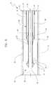
- FIG. 1is a schematic longitudinal cross-sectional view of distal and proximal portions of an embodiment of the invention.
- FIG. 2is a longitudinal cross-sectional view of the distal portion of the embodiment depicted in FIG. 1 shown during retraction of the membrane and sheath.
- FIG. 3is a longitudinal cross-sectional view of the embodiment depicted in FIG. 1 shown with the membrane and sheath fully retracted from the stent.
- FIG. 4is a longitudinal cross-sectional view of an alternative embodiment of the invention.
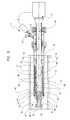
- FIG. 5is a longitudinal cross-sectional view of an alternative embodiment of the invention.
- a delivery system 10which includes a catheter 20 which is configured to deliver a stent 30 , which in at least one embodiment is a self-expanding stent.
- Catheter 20includes a catheter shaft or inner shaft 22 , a portion of which defines a stent receiving region 24 .
- Catheter shaft 22may further define a guidewire lumen 26 through which a guidewire 28 may be passed in order to advance the catheter to a predetermined position in a body lumen or vessel.
- the shaft 22may be configured as a fixed-wire catheter.
- the catheter 20may be any type of catheter desired and in some embodiments may include a catheter shaft 22 having a substantially hexagonal cross-sectional shape, such as is described in the Inventor's concurrently filed application Ser. No. 10/912,845 entitled Medical Device Delivery System, the entire content of which is incorporated herein by reference.
- a stent 30may be a self-expanding stent which is disposed about the stent receiving region 24 of the catheter shaft 22 .
- the stentmay be at least partially constructed from one or more of the following shape memory materials: nitinol, shape-memory polymer(s), etc., but may include other material or materials as well.
- the stentis at least partially constructed of stainless steel, cobalt, chromium, titanium, nickel, and any combinations or alloys thereof.
- the stentincludes one or more areas, bands, coatings, members etc that is (are) detectable by imaging modalities such as X-Ray, MRI or ultrasound. In some embodiments at least a portion of the stent 30 is at least partially radiopaque.
- the stent 30may include one or more therapeutic and/or lubricious coatings 50 applied thereto.
- a therapeutic agentmay be included with the stent.
- the agentis placed on the stent in the form of a coating 50 .
- the coating 50includes at least one therapeutic agent and at least one polymer agent.
- a therapeutic agentmay be a drug or other pharmaceutical product such as non-genetic agents, genetic agents, cellular material, etc.
- suitable non-genetic therapeutic agentsinclude but are not limited to: anti-thrombogenic agents such as heparin, heparin derivatives, vascular cell growth promoters, growth factor inhibitors, Paclitaxel, etc.
- an agentincludes a genetic therapeutic agent, such a genetic agent may include but is not limited to: DNA, RNA and their respective derivatives and/or components; hedgehog proteins, etc.
- the cellular materialmay include but is not limited to: cells of human origin and/or non-human origin as well as their respective components and/or derivatives thereof.
- the agentmay be a polystyrene-polyisobutylene-polystyrene triblock copolymer (SIBS), polyethylene oxide, silicone rubber and/or any other suitable substrate.
- SIBSpolystyrene-polyisobutylene-polystyrene triblock copolymer
- silicone rubberany other suitable substrate.
- the at least a portion of the stentmay include a stent covering.
- the coveringmay be constructed of a variety of materials such as Dacron, PTFE, etc.
- the coveringcomprises at least one therapeutic agent.
- the stent 30is preferably configured to be at least partially self-expanding or have self-expanding characteristics.
- self-expandingrefers to the tendency of the stent to return to a predetermined diameter when unrestrained from the catheter, such as in the manner depicted in FIGS. 1-3 .
- the stentis restrained in its reduced diameter or pre-delivery configuration by retractable sheath 40 which is disposed about the entire length of the stent 30 prior to delivery.
- the sheath 40includes a stent retaining region 42 , which refers to that region of the sheath 40 which is disposed about the stent 30 prior to delivery.
- a stent retaining region 42Engaged to a portion of the stent retaining region 42 is a roll back sleeve or membrane 44 .
- the sheath 40is retracted proximally, which causes the membrane 44 to roll back off of the stent in the manner illustrated in FIGS. 2-3 .
- the membrane 44comprises a distal end region 43 and a proximal end region 45 .
- the proximal end region 45is engaged to a portion of the inner shaft 22 proximal to the stent receiving region 24 .
- the distal end region 43 of the membraneis engaged to a distal end portion 47 of the sheath 40 at an engagement region 46 .
- the membrane 44 and sheath 40may be engaged together by any mechanism and/or configuration desired.
- region 43 and portion 47may be engaged together by chemical, or adhesive welding or bonding, fusion or heat welding, ultrasonic welding, etc.; they may be mechanically engaged along complementary surfaces; an additional component such as a fastener or other device may be utilized to secure the components together, etc.
- the membrane 44 and the sheath 40may be butt-welded or joined, or lap-welded or joined.
- the distal end region 43 of the membrane 44can be folded back upon itself to engage the distal end region of the sheath 40 .
- This folded arrangementprovides the membrane 44 with a continuous bend region 59 which not only aids in providing the membrane 44 with the tendency to roll back upon itself rather than buckle or slide during retraction, but also aids in the formation of a potential gap between the membrane 44 and sheath 40 proximal to their engagement region 46 .
- this “gap”functions as a fluid lumen or chamber 60 into which a fluid, represented by arrows 62 , from a fluid source 76 (such as a syringe, etc) may be transported via a fluid port 73 at the proximal end region 74 of the catheter 20 .
- the proximal end region 74 of the cathetermay have any handle configuration desired and may have any desired mechanism for regulating the flow of fluid 62 into and/or out of the chamber 60 .
- the catheter 20may include a pressure gauge 75 or other mechanism for monitoring and regulating to volume, flow rate, and/or pressure of the fluid 62 with in the catheter.
- the fluid chamber 60acts as a lumen to transport the fluid distally into the area of the stent retaining region of the sheath 40 .
- the proximal portion of the chamber or lumen 60is defined by the sheath 40 and the inner shaft 22 .
- the distal region of the chamber 60is defined by the sheath 40 and the membrane 44 .
- fluid 62may be in the form of a coating, such as a lubricious hydrogel, saline, etc. which aids in reducing the potential frictional interactions between the sheath 40 and membrane 44
- a volume of fluid 62may be injected into the lumen 60 under a predetermined pressure which is maintained during the stent delivery process depicted in FIGS. 2 and 3 .
- the use of fluid 62 under pressurekeeps the gap between the sheath 40 and membrane 44 open throughout the retraction process effectively minimizing any sliding friction therebetween, as well as limiting the frictional forces resulting from the stent's tendency to push outward against the sheath 40 . As illustrated in FIG.
- the pressure exerted by the fluid 62 against the membrane 44maintains the membrane 44 over the stent and provides the folded over membrane 44 with a turgid-like state sufficient to retain a portion of the stent 30 thereunder in the reduced state until the membrane 44 is retracted.
- the pressure exerted by fluid 62 on the membrane 44may be monitored and regulated by the pressure gauge 75 , such as is shown in FIG. 1 .
- a desired pressure of fluid 62may be maintained within the chamber 60 by the use of any of a variety of devices such as stop-cocks, relief valves, etc.
- the stentWhen the sheath 40 and the membrane 44 are fully withdrawn from about the stent 30 , the stent is delivered into a desired location within a body lumen or vessel.
- the sheath 40and particularly the distal portion or stent retaining region 42 of the sheath, is configured to retain the stent 30 in its reduced or pre-delivery diameter
- at least the stent retaining region 42 of the sheath 40is constructed to have sufficient hoop strength to prevent the stent from expanding off of the stent receiving region 24 until the sheath 40 is retracted.
- At least the stent retaining region 42 of the sheath 40may be constructed from one or more of the materials including but not limited to: polymer materials such as Pebax, Hytrel, Arnitel, Nylon, etc.
- the stiffness of the sheath 40can be varied by changing the polymer durometers from the proximal end to the distal end by any manner desired.
- the sheath 40comprises a multi-layer construction wherein one or more materials are layered, braided or otherwise combined to form the sheath 40 .
- the sheath 40may be provided with a PTFE liner or such a liner may be absent. Where a liner is provided, an inner PTFE liner may be braided with an additional polymer as desired.
- the sheath 40is of the same or similar construction as a guide catheter.
- the sheath 40is at least partially constructed of a clear polymer.
- a clear polymermay be used to provide the sheath 40 with a substantially clear distal end region. The clear distal end would allow for viewing the stent or implant device in a constrained state under the sheath.
- the inside of the sheathis coated for enhanced lubricity.
- the sheath 40While the stent retaining region 42 of the sheath 40 is typically constructed to have greater hoop strength than the membrane 44 , the sheath may be less flexible than the membrane 44 as well.
- the membrane 44may be at least partially constructed of one or more of a variety of flexible materials such as including but not limited to: Pebax, PET, Nylon, POC, Polyurethane, etc.
- the material of the membrane 44may include those which are nanoceramic for added durability.
- the membrane 44is at least partially made from one or more polymers with surface alterations such as plasma treatment for enhanced lubricity.
- the membrane 44comprises one or more layers of material.
- one or both sides of the membrane 44are coated and/or provided with surface enhancements. Coating can include silicones or other substances to enhance lubricity.
- the membrane 44is at least partially constructed from those materials from which medical balloons are known to be manufactured from. Such membrane material may be blown or extruded to any dimensions desired.
- the wall thickness of the membranemay vary and may be about 0.001 inches to no more than about 0.005 inches thick. In at least one embodiment the thickness of the membrane is less than about 0.001 inches.
- the membrane 44is a single layer membrane folded over upon itself at the distal end region 43 whereupon it is engaged to the sheath 40 .
- the sheath 40is retracted, the membrane 44 is pulled back off of the stent 30 as the outside fold 52 of the membrane rolls proximally on top of the inner fold 54 proximally until the entire membrane 44 is rolled off of the stent 30 such as is depicted in FIGS. 2-3 .
- a lubricant or other fluid 62may be provided within the lumen 60 to encourage the rolling action of the folds 52 and 54 and/or separate the folds.
- the fluid 62may be any type of “inflation fluid” such as may be utilized in balloon catheters which are known, and/or may be any sort of biocompatible fluid or lubricant such as is described in U.S. Pat. No. 5,693,034, the entire content of which is incorporated herein by reference.
- fluid 62is a liquid.
- a hub, flange, protrusion(s), marker or other member 70 and 72may be positioned proximally and/or adjacent to the stent receiving region 24 .
- member 72may also be provided with a diameter sufficiently greater than the diameter of the stent in the reduced state, to thereby prevent the stent from being inadvertently displaced in the proximal direction.
- the stent 30may be crimped onto, or disposed about, one or more of the members 70 and/or 72 , and/or the catheter 20 may be provided any of the variety of stent retaining mechanisms that are known.
- Members 70 and/or 72may also include any known or later developed type of fixation system for reducing the likelihood of stent displacement prior to and/or during deployment.
- Members 70 and/or 72may be configured to be detectable by imaging modalities such as X-Ray, MRI or ultrasound. In some embodiments at least a portion of one or both members is at least partially radiopaque.
- the catheter 20is provided with a secondary lumen 80 which is formed between an intermediate shaft or mid-shaft 82 and the inner shaft 22 proximal to the stent receiving region 24 .
- the proximal end region 45 of the membrane 44is engaged to a distal portion 84 of the mid-shaft 82 .
- This modified system 10provides a secondary lumen 80 which extends into the stent receiving region 24 of the catheter 20 which underlies the membrane 44 .
- the secondary lumen 80provides a flush path through which a fluid 64 may be transported to the stent receiving region 24 during or prior to delivery of the stent 30 .
- Fluid 64may be similar or different than fluid 62 .
- Flushing the stent receiving region 24 prior to delivery of the stent 30 and/or prior to use of the device 10will not only purge the region 24 of air but will also act to reduce frictional engagement of the stent 30 and the membrane 44 prior to and/or during retraction of the membrane 44 . Flushing can also be used to hydrate the shaft walls and/or the stent.
- a system 10 of the type shown in FIGS. 1-3may also be provided with a flush path for flushing the stent receiving region 24 of the catheter 20 prior to use.
- a flush pathis defined by the guidewire lumen 26 and one or more holes or ports 86 through the stent receiving region 24 of the catheter shaft 22 .
- Ports 86provide fluid communication between the guidewire lumen 26 and the stent receiving region 24 .
- the ports 86may be configured as a one-way valve to allow fluid to exit the guidewire lumen 26 but not re-enter.
- any dependent claim which followsshould be taken as alternatively written in a multiple dependent form from all prior claims which possess all antecedents referenced in such dependent claim if such multiple dependent format is an accepted format within the jurisdiction (e.g. each claim depending directly from claim 1 should be alternatively taken as depending from all previous claims).
- each claim depending directly from claim 1should be alternatively taken as depending from all previous claims.
- the following dependent claimsshould each be also taken as alternatively written in each singly dependent claim format which creates a dependency from a prior antecedent-possessing claim other than the specific claim listed in such dependent claim below.
Landscapes
- Health & Medical Sciences (AREA)
- Engineering & Computer Science (AREA)
- Biomedical Technology (AREA)
- Cardiology (AREA)
- Oral & Maxillofacial Surgery (AREA)
- Transplantation (AREA)
- Heart & Thoracic Surgery (AREA)
- Vascular Medicine (AREA)
- Life Sciences & Earth Sciences (AREA)
- Animal Behavior & Ethology (AREA)
- General Health & Medical Sciences (AREA)
- Public Health (AREA)
- Veterinary Medicine (AREA)
- Media Introduction/Drainage Providing Device (AREA)
- Materials For Medical Uses (AREA)
- Prostheses (AREA)
Abstract
Description
Claims (19)
Priority Applications (7)
| Application Number | Priority Date | Filing Date | Title |
|---|---|---|---|
| US10/912,917US7955370B2 (en) | 2004-08-06 | 2004-08-06 | Stent delivery system |
| JP2007524824AJP4881302B2 (en) | 2004-08-06 | 2005-07-14 | Medical device including a stent delivery system |
| DE602005019423TDE602005019423D1 (en) | 2004-08-06 | 2005-07-14 | SYSTEM FOR ATTACHING A STENT |
| AT05772202TATE457704T1 (en) | 2004-08-06 | 2005-07-14 | SYSTEM FOR APPLYING A STENT |
| PCT/US2005/025166WO2006020028A1 (en) | 2004-08-06 | 2005-07-14 | Stent delivery system |
| CA2567362ACA2567362C (en) | 2004-08-06 | 2005-07-14 | Stent delivery system |
| EP05772202AEP1788972B1 (en) | 2004-08-06 | 2005-07-14 | Stent delivery system |
Applications Claiming Priority (1)
| Application Number | Priority Date | Filing Date | Title |
|---|---|---|---|
| US10/912,917US7955370B2 (en) | 2004-08-06 | 2004-08-06 | Stent delivery system |
Publications (2)
| Publication Number | Publication Date |
|---|---|
| US20060030923A1 US20060030923A1 (en) | 2006-02-09 |
| US7955370B2true US7955370B2 (en) | 2011-06-07 |
Family
ID=35063173
Family Applications (1)
| Application Number | Title | Priority Date | Filing Date |
|---|---|---|---|
| US10/912,917Expired - Fee RelatedUS7955370B2 (en) | 2004-08-06 | 2004-08-06 | Stent delivery system |
Country Status (7)
| Country | Link |
|---|---|
| US (1) | US7955370B2 (en) |
| EP (1) | EP1788972B1 (en) |
| JP (1) | JP4881302B2 (en) |
| AT (1) | ATE457704T1 (en) |
| CA (1) | CA2567362C (en) |
| DE (1) | DE602005019423D1 (en) |
| WO (1) | WO2006020028A1 (en) |
Cited By (38)
| Publication number | Priority date | Publication date | Assignee | Title |
|---|---|---|---|---|
| US20090299449A1 (en)* | 2005-05-19 | 2009-12-03 | Mikolaj Witold Styrc | Kit for inserting a cavity-treatment element and method for preparing an associated treatment element |
| US20130204345A1 (en)* | 2011-08-12 | 2013-08-08 | Edward H. Cully | Evertable sheath devices, systems, and methods |
| US8579958B2 (en) | 2002-03-12 | 2013-11-12 | Covidien Lp | Everting stent and stent delivery system |
| US8591566B2 (en) | 2012-02-23 | 2013-11-26 | Covidien Lp | Methods and apparatus for luminal stenting |
| US9072624B2 (en) | 2012-02-23 | 2015-07-07 | Covidien Lp | Luminal stenting |
| US9078659B2 (en) | 2012-04-23 | 2015-07-14 | Covidien Lp | Delivery system with hooks for resheathability |
| US9192499B2 (en) | 2013-03-11 | 2015-11-24 | Cook Medical Technologies Llc | Inner catheter for a self-expanding medical device delivery system with a closed coil wire |
| US9474639B2 (en) | 2013-08-27 | 2016-10-25 | Covidien Lp | Delivery of medical devices |
| US9498364B2 (en) | 2013-03-29 | 2016-11-22 | Cook Medical Technologies Llc | Medical device delivery system and method of flushing same |
| US9636244B2 (en)* | 2015-04-09 | 2017-05-02 | Mubin I. Syed | Apparatus and method for proximal to distal stent deployment |
| US9724222B2 (en) | 2012-07-20 | 2017-08-08 | Covidien Lp | Resheathable stent delivery system |
| US9782186B2 (en) | 2013-08-27 | 2017-10-10 | Covidien Lp | Vascular intervention system |
| US9980838B2 (en) | 2015-10-30 | 2018-05-29 | Ram Medical Innovations Llc | Apparatus and method for a bifurcated catheter for use in hostile aortic arches |
| US10130500B2 (en) | 2013-07-25 | 2018-11-20 | Covidien Lp | Methods and apparatus for luminal stenting |
| US10173031B2 (en) | 2016-06-20 | 2019-01-08 | Mubin I. Syed | Interchangeable flush/selective catheter |
| US10278847B2 (en) | 2015-08-11 | 2019-05-07 | Mokita Medical Gmbh I.Gr. | Systems and methods for removing air from medical devices |
| US10327929B2 (en) | 2015-10-30 | 2019-06-25 | Ram Medical Innovations, Llc | Apparatus and method for stabilization of procedural catheter in tortuous vessels |
| US10376396B2 (en) | 2017-01-19 | 2019-08-13 | Covidien Lp | Coupling units for medical device delivery systems |
| US10492936B2 (en) | 2015-10-30 | 2019-12-03 | Ram Medical Innovations, Llc | Apparatus and method for improved access of procedural catheter in tortuous vessels |
| US10588766B2 (en) | 2012-11-21 | 2020-03-17 | Ram Medical Innovations, Llc | Steerable intravascular anchor and method of operation |
| US10610394B2 (en) | 2015-08-11 | 2020-04-07 | Mokita Medical Gmbh | Systems and methods for using perfluorocarbons to remove gases from medical devices |
| US10779976B2 (en) | 2015-10-30 | 2020-09-22 | Ram Medical Innovations, Llc | Apparatus and method for stabilization of procedural catheter in tortuous vessels |
| US10786377B2 (en) | 2018-04-12 | 2020-09-29 | Covidien Lp | Medical device delivery |
| US10857014B2 (en) | 2018-02-18 | 2020-12-08 | Ram Medical Innovations, Llc | Modified fixed flat wire bifurcated catheter and its application in lower extremity interventions |
| US11020256B2 (en) | 2015-10-30 | 2021-06-01 | Ram Medical Innovations, Inc. | Bifurcated “Y” anchor support for coronary interventions |
| US11071637B2 (en) | 2018-04-12 | 2021-07-27 | Covidien Lp | Medical device delivery |
| US11123209B2 (en) | 2018-04-12 | 2021-09-21 | Covidien Lp | Medical device delivery |
| US11166806B2 (en) | 2014-01-10 | 2021-11-09 | W. L. Gore & Associates, Inc. | Implantable intraluminal device |
| US11291570B2 (en) | 2018-04-27 | 2022-04-05 | Cook Medical Technologies Llc | Hybrid stent and delivery system |
| US11413174B2 (en) | 2019-06-26 | 2022-08-16 | Covidien Lp | Core assembly for medical device delivery systems |
| US11413176B2 (en) | 2018-04-12 | 2022-08-16 | Covidien Lp | Medical device delivery |
| US11540933B2 (en) | 2017-10-11 | 2023-01-03 | W. L. Gore & Associates, Inc. | Implantable medical device constraint and deployment apparatus |
| US11690743B2 (en) | 2019-02-15 | 2023-07-04 | Boston Scientific Scimed, Inc. | Stent delivery system |
| US11801155B2 (en) | 2014-03-06 | 2023-10-31 | W. L. Gore & Associates, Inc. | Implantable medical device constraint and deployment apparatus |
| US11903856B1 (en) | 2013-03-05 | 2024-02-20 | W. L. Gore & Associates, Inc. | Tapered sleeve |
| US11944558B2 (en) | 2021-08-05 | 2024-04-02 | Covidien Lp | Medical device delivery devices, systems, and methods |
| US12042413B2 (en) | 2021-04-07 | 2024-07-23 | Covidien Lp | Delivery of medical devices |
| US12109137B2 (en) | 2021-07-30 | 2024-10-08 | Covidien Lp | Medical device delivery |
Families Citing this family (113)
| Publication number | Priority date | Publication date | Assignee | Title |
|---|---|---|---|---|
| ATE415895T1 (en) | 2001-07-06 | 2008-12-15 | Angiomed Ag | DELIVERY SYSTEM HAVING A SELF-EXPANDING STENT SLIDE ASSEMBLY AND A QUICK-CHANGE CONFIGURATION |
| US6863683B2 (en) | 2001-09-19 | 2005-03-08 | Abbott Laboratoris Vascular Entities Limited | Cold-molding process for loading a stent onto a stent delivery system |
| GB0123633D0 (en) | 2001-10-02 | 2001-11-21 | Angiomed Ag | Stent delivery system |
| EP1589903B1 (en) | 2003-01-15 | 2016-01-13 | Angiomed GmbH & Co. Medizintechnik KG | Trans-luminal surgical device |
| GB0327306D0 (en)* | 2003-11-24 | 2003-12-24 | Angiomed Gmbh & Co | Catheter device |
| GB0309616D0 (en) | 2003-04-28 | 2003-06-04 | Angiomed Gmbh & Co | Loading and delivery of self-expanding stents |
| US7393358B2 (en)* | 2004-08-17 | 2008-07-01 | Boston Scientific Scimed, Inc. | Stent delivery system |
| WO2006042114A1 (en) | 2004-10-06 | 2006-04-20 | Cook, Inc. | Emboli capturing device having a coil and method for capturing emboli |
| US20060116572A1 (en)* | 2004-12-01 | 2006-06-01 | Case Brian C | Sensing delivery system for intraluminal medical devices |
| DE102006039823A1 (en)* | 2005-02-25 | 2008-03-20 | Strecker, Ernst Peter, Prof. Dr. med. | Catheter-stent-device for treatment of e.g. body hollow organ, has catheter surrounding stent, where catheter and stent are movable by difference of pressure developed by pressuring medium consisting of liquid or gas for implanting stent |
| US7632296B2 (en)* | 2005-03-03 | 2009-12-15 | Boston Scientific Scimed, Inc. | Rolling membrane with hydraulic recapture means for self expanding stent |
| US8221446B2 (en) | 2005-03-15 | 2012-07-17 | Cook Medical Technologies | Embolic protection device |
| US8945169B2 (en) | 2005-03-15 | 2015-02-03 | Cook Medical Technologies Llc | Embolic protection device |
| US8435279B2 (en)* | 2005-06-14 | 2013-05-07 | Advanced Cardiovascular Systems, Inc. | Delivery system for a device such as a stent |
| US8187298B2 (en) | 2005-08-04 | 2012-05-29 | Cook Medical Technologies Llc | Embolic protection device having inflatable frame |
| US8377092B2 (en)* | 2005-09-16 | 2013-02-19 | Cook Medical Technologies Llc | Embolic protection device |
| US8632562B2 (en) | 2005-10-03 | 2014-01-21 | Cook Medical Technologies Llc | Embolic protection device |
| US8182508B2 (en) | 2005-10-04 | 2012-05-22 | Cook Medical Technologies Llc | Embolic protection device |
| US8252017B2 (en) | 2005-10-18 | 2012-08-28 | Cook Medical Technologies Llc | Invertible filter for embolic protection |
| US7780714B2 (en)* | 2005-11-01 | 2010-08-24 | Cordis Corporation | Implant delivery apparatus |
| US8216269B2 (en)* | 2005-11-02 | 2012-07-10 | Cook Medical Technologies Llc | Embolic protection device having reduced profile |
| US8152831B2 (en) | 2005-11-17 | 2012-04-10 | Cook Medical Technologies Llc | Foam embolic protection device |
| US7621946B2 (en)* | 2006-03-06 | 2009-11-24 | Boston Scientific Scimed, Inc. | Implantable medical endoprosthesis delivery system with hub |
| US20070208350A1 (en)* | 2006-03-06 | 2007-09-06 | Gunderson Richard C | Implantable medical endoprosthesis delivery systems |
| US20070208405A1 (en)* | 2006-03-06 | 2007-09-06 | Boston Scientific Scimed, Inc. | Stent delivery catheter |
| US8333000B2 (en) | 2006-06-19 | 2012-12-18 | Advanced Cardiovascular Systems, Inc. | Methods for improving stent retention on a balloon catheter |
| US20080071307A1 (en) | 2006-09-19 | 2008-03-20 | Cook Incorporated | Apparatus and methods for in situ embolic protection |
| US8177798B2 (en)* | 2006-12-05 | 2012-05-15 | Tyco Healthcare Group Lp | Adhesive coated stent and insertion instrument |
| US9901434B2 (en) | 2007-02-27 | 2018-02-27 | Cook Medical Technologies Llc | Embolic protection device including a Z-stent waist band |
| US8764816B2 (en)* | 2007-05-07 | 2014-07-01 | W. L. Gore & Associates, Inc. | Stent delivery and deployment system |
| US7981148B2 (en)* | 2007-05-16 | 2011-07-19 | Boston Scientific Scimed, Inc. | Stent delivery catheter |
| US9138307B2 (en) | 2007-09-14 | 2015-09-22 | Cook Medical Technologies Llc | Expandable device for treatment of a stricture in a body vessel |
| US8419748B2 (en) | 2007-09-14 | 2013-04-16 | Cook Medical Technologies Llc | Helical thrombus removal device |
| US8252018B2 (en) | 2007-09-14 | 2012-08-28 | Cook Medical Technologies Llc | Helical embolic protection device |
| CA2701576C (en)* | 2007-10-17 | 2016-06-21 | Angiomed Gmbh & Co. Medizintechnik Kg | Delivery system for a self-expanding device for placement in a bodily lumen |
| US20090187211A1 (en)* | 2007-12-21 | 2009-07-23 | Abbott Laboratories | Vena cava filter having hourglass shape |
| US8845712B2 (en) | 2008-01-15 | 2014-09-30 | W. L. Gore & Associates, Inc. | Pleated deployment sheath |
| CA2720466A1 (en)* | 2008-05-09 | 2009-11-12 | Juergen Dorn | Method of loading a stent into a sheath |
| GB0815339D0 (en)* | 2008-08-21 | 2008-10-01 | Angiomed Ag | Method of loading a stent into a sheath |
| US9750625B2 (en) | 2008-06-11 | 2017-09-05 | C.R. Bard, Inc. | Catheter delivery device |
| GB0810749D0 (en) | 2008-06-11 | 2008-07-16 | Angiomed Ag | Catherter delivery device |
| US20090312832A1 (en)* | 2008-06-13 | 2009-12-17 | Cook Incorporated | Slip layer delivery catheter |
| US8721714B2 (en)* | 2008-09-17 | 2014-05-13 | Medtronic Corevalve Llc | Delivery system for deployment of medical devices |
| EP2668934B1 (en) | 2008-12-12 | 2017-05-10 | Abbott Laboratories Vascular Enterprises Limited | Process for loading a stent onto a stent delivery system |
| US8388644B2 (en) | 2008-12-29 | 2013-03-05 | Cook Medical Technologies Llc | Embolic protection device and method of use |
| GB0823716D0 (en)* | 2008-12-31 | 2009-02-04 | Angiomed Ag | Stent delivery device with rolling stent retaining sheath |
| GB0901496D0 (en) | 2009-01-29 | 2009-03-11 | Angiomed Ag | Delivery device for delivering a stent device |
| US20100249815A1 (en)* | 2009-03-25 | 2010-09-30 | Cook Incorporated | Everted sheath thrombectomy device |
| JP5466882B2 (en)* | 2009-05-21 | 2014-04-09 | 川澄化学工業株式会社 | Tubular treatment device placement device |
| GB0909319D0 (en) | 2009-05-29 | 2009-07-15 | Angiomed Ag | Transluminal delivery system |
| US20110009943A1 (en)* | 2009-07-09 | 2011-01-13 | Paul Ram H | Delivery system with medical device release by evertable sleeve |
| US8936634B2 (en) | 2009-07-15 | 2015-01-20 | W. L. Gore & Associates, Inc. | Self constraining radially expandable medical devices |
| US8435282B2 (en) | 2009-07-15 | 2013-05-07 | W. L. Gore & Associates, Inc. | Tube with reverse necking properties |
| WO2011017189A1 (en)* | 2009-08-04 | 2011-02-10 | Wilson-Cook Medical Inc. | Roll sleeve mechanism for proximal release stent delivery device |
| US20110106234A1 (en)* | 2009-10-30 | 2011-05-05 | Axel Grandt | Interluminal medical treatment devices and methods |
| US20110118817A1 (en)* | 2009-11-17 | 2011-05-19 | Boston Scientific Scimed, Inc. | Stent delivery system |
| GB0921238D0 (en) | 2009-12-03 | 2010-01-20 | Angiomed Ag | Stent device delivery system and method of making such |
| GB0921237D0 (en)* | 2009-12-03 | 2010-01-20 | Angiomed Ag | Stent device delivery system and method of making such |
| GB0921240D0 (en) | 2009-12-03 | 2010-01-20 | Angiomed Ag | Stent device delivery system and method of making such |
| GB0921236D0 (en)* | 2009-12-03 | 2010-01-20 | Angiomed Ag | Stent device delivery system and method of making such |
| US8016872B2 (en)* | 2009-12-22 | 2011-09-13 | Cook Medical Technologies Llc | Deployment and dilation with an expandable roll sock delivery system |
| US8740976B2 (en) | 2010-04-21 | 2014-06-03 | Medtronic, Inc. | Transcatheter prosthetic heart valve delivery system with flush report |
| GB201010766D0 (en) | 2010-06-25 | 2010-08-11 | Angiomed Ag | Delivery system for a self-expanding implant |
| US8585748B2 (en) | 2010-08-12 | 2013-11-19 | Cook Medical Technologies Llc | Vacuum assist delivery system |
| EP2616009A2 (en)* | 2010-09-17 | 2013-07-24 | St. Jude Medical, Cardiology Division, Inc. | Improved preparation methods for transcatheter heart valve delivery systems |
| WO2012054178A1 (en) | 2010-10-21 | 2012-04-26 | Boston Scientific Scimed, Inc. | Stent delivery system with a rolling membrane |
| US8784468B2 (en) | 2010-11-17 | 2014-07-22 | Boston Scientific Scimed, Inc. | Stent delivery systems and locking members for use with stent delivery systems |
| EP3375413B1 (en) | 2010-11-17 | 2025-03-26 | Boston Scientific Scimed, Inc. | Stent delivery system |
| EP2640324B1 (en) | 2010-11-17 | 2015-02-18 | Boston Scientific Scimed, Inc. | Stent delivery system |
| GB201020373D0 (en) | 2010-12-01 | 2011-01-12 | Angiomed Ag | Device to release a self-expanding implant |
| EP2510972B1 (en)* | 2011-04-14 | 2014-08-06 | Biotronik AG | Catheter device |
| US20120330342A1 (en)* | 2011-06-27 | 2012-12-27 | Jones Donald K | Systems and devices for intralumenal implantation |
| US20120330350A1 (en)* | 2011-06-27 | 2012-12-27 | Jones Donald K | Methods and systems for performing thrombectomy procedures |
| US8945146B2 (en) | 2011-10-24 | 2015-02-03 | Medtronic, Inc. | Delivery system assemblies and associated methods for implantable medical devices |
| WO2013067168A1 (en) | 2011-11-02 | 2013-05-10 | Boston Scientific Scimed, Inc. | Stent delivery systems and methods for use |
| US8721587B2 (en) | 2011-11-17 | 2014-05-13 | Medtronic, Inc. | Delivery system assemblies and associated methods for implantable medical devices |
| US9216293B2 (en) | 2011-11-17 | 2015-12-22 | Medtronic, Inc. | Delivery system assemblies for implantable medical devices |
| US10213187B1 (en) | 2012-01-25 | 2019-02-26 | Mubin I. Syed | Method and apparatus for percutaneous superficial temporal artery access for carotid artery stenting |
| EP3281608B1 (en) | 2012-02-10 | 2020-09-16 | CVDevices, LLC | Medical product comprising a frame and visceral pleura |
| US9271855B2 (en)* | 2012-05-09 | 2016-03-01 | Abbott Cardiovascular Systems Inc. | Catheter having hydraulic actuator with tandem chambers |
| US20130304180A1 (en) | 2012-05-09 | 2013-11-14 | Michael L. Green | Catheter having dual balloon hydraulic actuator |
| US9011513B2 (en) | 2012-05-09 | 2015-04-21 | Abbott Cardiovascular Systems Inc. | Catheter having hydraulic actuator |
| US9381326B2 (en) | 2012-06-15 | 2016-07-05 | W. L. Gore & Associates, Inc. | Vascular occlusion and drug delivery devices, systems, and methods |
| US9364358B2 (en) | 2012-07-27 | 2016-06-14 | Medinol Ltd. | Catheter with retractable cover and pressurized fluid |
| CH707319A1 (en)* | 2012-12-11 | 2014-06-13 | Carag Ag | Stent applicator. |
| CA2900862C (en) | 2013-02-11 | 2017-10-03 | Cook Medical Technologies Llc | Expandable support frame and medical device |
| US9333077B2 (en) | 2013-03-12 | 2016-05-10 | Medtronic Vascular Galway Limited | Devices and methods for preparing a transcatheter heart valve system |
| US9283101B2 (en) | 2013-03-12 | 2016-03-15 | Abbott Cardiovascular Systems Inc. | Catheter having hydraulic actuator and locking system |
| US10420662B2 (en) | 2013-03-12 | 2019-09-24 | Abbott Cardiovascular Systems Inc. | Catheter having movable tubular structure and proximal stopper |
| US10531971B2 (en) | 2013-03-12 | 2020-01-14 | Abbott Cardiovascular System Inc. | Balloon catheter having hydraulic actuator |
| EP2813195A1 (en) | 2013-06-13 | 2014-12-17 | Cardiatis S.A. | Stent delivery system |
| US10327883B2 (en)* | 2013-11-28 | 2019-06-25 | Innovations Ltd. | Filtration and entrapment apparatus and method of use |
| EP3206634B1 (en)* | 2014-10-14 | 2019-07-03 | Colospan Ltd. | Apparatus for delivering a device to a hollow organ |
| US10583022B2 (en)* | 2014-11-19 | 2020-03-10 | Boston Scientific Scimed, Inc. | Stent delivery systems with a reconstraining member |
| US10159587B2 (en) | 2015-01-16 | 2018-12-25 | Boston Scientific Scimed, Inc. | Medical device delivery system with force reduction member |
| US10080675B2 (en) | 2015-08-24 | 2018-09-25 | Abbott Cardiovascular Systems Inc. | System and method for conditioning an endoprosthesis |
| US11351048B2 (en) | 2015-11-16 | 2022-06-07 | Boston Scientific Scimed, Inc. | Stent delivery systems with a reinforced deployment sheath |
| CN108601925B (en) | 2015-12-04 | 2021-06-29 | 项目莫里股份有限公司 | Input and articulation system for catheters and other uses |
| JP6686156B2 (en) | 2016-02-26 | 2020-04-22 | ボストン サイエンティフィック サイムド,インコーポレイテッドBoston Scientific Scimed,Inc. | Methods of manufacturing medical devices and stent delivery systems |
| US11420021B2 (en) | 2016-03-25 | 2022-08-23 | Project Moray, Inc. | Fluid-actuated displacement for catheters, continuum manipulators, and other uses |
| EP3432834B1 (en)* | 2016-03-25 | 2021-01-13 | Project Moray, Inc. | Fluid-actuated sheath displacement and articulation behavior improving systems for catheters |
| JP2019527115A (en)* | 2016-08-02 | 2019-09-26 | ボストン サイエンティフィック サイムド,インコーポレイテッドBoston Scientific Scimed,Inc. | Stent delivery system |
| JP6564757B2 (en)* | 2016-11-11 | 2019-08-21 | 日本ライフライン株式会社 | Treatment device |
| US10716666B2 (en)* | 2016-12-05 | 2020-07-21 | Medtronic Vascular, Inc. | Prosthetic heart valve delivery system with controlled expansion |
| CN106580531B (en)* | 2017-01-24 | 2018-03-23 | 南华大学 | Delivery system for expandable stent |
| ES2982356T3 (en)* | 2017-04-21 | 2024-10-15 | Merit Medical Systems Inc | Deployable endoprostheses and devices, and related systems |
| US11013627B2 (en) | 2018-01-10 | 2021-05-25 | Boston Scientific Scimed, Inc. | Stent delivery system with displaceable deployment mechanism |
| US11065139B2 (en)* | 2019-01-08 | 2021-07-20 | Covidien Lp | Apparatuses for stent delivery and positioning to cover an access site |
| JP7399971B2 (en) | 2019-02-13 | 2023-12-18 | ボストン サイエンティフィック サイムド,インコーポレイテッド | stent delivery system |
| CN114469450A (en)* | 2020-11-13 | 2022-05-13 | 爱德华兹生命科学公司 | Apparatus and method for controlling fluid flow in a delivery device |
| EP4539783A1 (en)* | 2022-06-16 | 2025-04-23 | Edwards Lifesciences Corporation | Fluid sealing mechanism for a catheter |
| CN117244152A (en)* | 2022-06-16 | 2023-12-19 | 爱德华兹生命科学公司 | Fluid seal mechanism for a catheter |
| GB2622233A (en)* | 2022-09-07 | 2024-03-13 | Cook Medical Technologies Llc | Medical balloon assembly, use thereof, and method of deploying a medical balloon assembly |
Citations (15)
| Publication number | Priority date | Publication date | Assignee | Title |
|---|---|---|---|---|
| WO1992005829A1 (en) | 1990-10-09 | 1992-04-16 | Scimed Life Systems, Inc. | Temporary stent and methods for use and manufacture |
| WO1996032078A1 (en) | 1995-04-14 | 1996-10-17 | Schneider (Usa) Inc. | Rolling membrane stent delivery device |
| US5681345A (en) | 1995-03-01 | 1997-10-28 | Scimed Life Systems, Inc. | Sleeve carrying stent |
| US5690644A (en)* | 1992-12-30 | 1997-11-25 | Schneider (Usa) Inc. | Apparatus for deploying body implantable stent |
| US5788707A (en) | 1995-06-07 | 1998-08-04 | Scimed Life Systems, Inc. | Pull back sleeve system with compression resistant inner shaft |
| JPH11313893A (en) | 1998-03-13 | 1999-11-16 | Cordis Corp | Feeding device for self extension type stent |
| US6066155A (en) | 1996-11-15 | 2000-05-23 | Schneider (Europe) A.G. | Captured sleeve and stent delivery device |
| US6221097B1 (en) | 1999-03-22 | 2001-04-24 | Scimed Life System, Inc. | Lubricated sleeve material for stent delivery |
| WO2001078627A1 (en) | 2000-04-12 | 2001-10-25 | Scimed Life Systems, Inc. | Stent delivery catheter with retractable balloon |
| US6331186B1 (en) | 1999-03-22 | 2001-12-18 | Scimed Life Systems, Inc. | End sleeve coating for stent delivery |
| US6350277B1 (en) | 1999-01-15 | 2002-02-26 | Scimed Life Systems, Inc. | Stents with temporary retaining bands |
| WO2002038084A2 (en) | 2000-11-10 | 2002-05-16 | Scimed Life Systems, Inc. | Improved rolling membrane stent delivery system |
| US6443880B2 (en) | 1998-09-23 | 2002-09-03 | Metso Paper, Inc. | Arrangement for removing oil in a roll |
| US6478814B2 (en) | 1999-06-14 | 2002-11-12 | Scimed Life Systems, Inc. | Stent securement sleeves and optional coatings and methods of use |
| US20050070997A1 (en)* | 2003-09-29 | 2005-03-31 | Ronan Thornton | Laminated drug-polymer coated stent with dipped and cured layers |
Family Cites Families (2)
| Publication number | Priority date | Publication date | Assignee | Title |
|---|---|---|---|---|
| US6090456A (en)* | 1997-05-03 | 2000-07-18 | The United States Of America As Represented By The Secretary Of The Air Force | Process for large area deposition of diamond-like carbon films |
| US6059813A (en)* | 1998-11-06 | 2000-05-09 | Scimed Life Systems, Inc. | Rolling membrane stent delivery system |
- 2004
- 2004-08-06USUS10/912,917patent/US7955370B2/ennot_activeExpired - Fee Related
- 2005
- 2005-07-14JPJP2007524824Apatent/JP4881302B2/ennot_activeExpired - Fee Related
- 2005-07-14WOPCT/US2005/025166patent/WO2006020028A1/enactiveApplication Filing
- 2005-07-14DEDE602005019423Tpatent/DE602005019423D1/ennot_activeExpired - Lifetime
- 2005-07-14EPEP05772202Apatent/EP1788972B1/ennot_activeCeased
- 2005-07-14ATAT05772202Tpatent/ATE457704T1/ennot_activeIP Right Cessation
- 2005-07-14CACA2567362Apatent/CA2567362C/ennot_activeExpired - Fee Related
Patent Citations (18)
| Publication number | Priority date | Publication date | Assignee | Title |
|---|---|---|---|---|
| WO1992005829A1 (en) | 1990-10-09 | 1992-04-16 | Scimed Life Systems, Inc. | Temporary stent and methods for use and manufacture |
| US5690644A (en)* | 1992-12-30 | 1997-11-25 | Schneider (Usa) Inc. | Apparatus for deploying body implantable stent |
| US5681345A (en) | 1995-03-01 | 1997-10-28 | Scimed Life Systems, Inc. | Sleeve carrying stent |
| WO1996032078A1 (en) | 1995-04-14 | 1996-10-17 | Schneider (Usa) Inc. | Rolling membrane stent delivery device |
| US6342066B1 (en) | 1995-06-07 | 2002-01-29 | Scimed Life Systems, Inc. | Pull back sleeve system with compression resistant inner shaft |
| US5788707A (en) | 1995-06-07 | 1998-08-04 | Scimed Life Systems, Inc. | Pull back sleeve system with compression resistant inner shaft |
| US6096045A (en) | 1995-06-07 | 2000-08-01 | Scimed Life Systems, Inc. | Pull back sleeve system with compression resistant inner shaft |
| US6066155A (en) | 1996-11-15 | 2000-05-23 | Schneider (Europe) A.G. | Captured sleeve and stent delivery device |
| JPH11313893A (en) | 1998-03-13 | 1999-11-16 | Cordis Corp | Feeding device for self extension type stent |
| US6443880B2 (en) | 1998-09-23 | 2002-09-03 | Metso Paper, Inc. | Arrangement for removing oil in a roll |
| US6942682B2 (en)* | 1998-11-06 | 2005-09-13 | Boston Scientific Scimed, Inc. | Rolling membrane stent delivery system |
| US6350277B1 (en) | 1999-01-15 | 2002-02-26 | Scimed Life Systems, Inc. | Stents with temporary retaining bands |
| US6331186B1 (en) | 1999-03-22 | 2001-12-18 | Scimed Life Systems, Inc. | End sleeve coating for stent delivery |
| US6221097B1 (en) | 1999-03-22 | 2001-04-24 | Scimed Life System, Inc. | Lubricated sleeve material for stent delivery |
| US6478814B2 (en) | 1999-06-14 | 2002-11-12 | Scimed Life Systems, Inc. | Stent securement sleeves and optional coatings and methods of use |
| WO2001078627A1 (en) | 2000-04-12 | 2001-10-25 | Scimed Life Systems, Inc. | Stent delivery catheter with retractable balloon |
| WO2002038084A2 (en) | 2000-11-10 | 2002-05-16 | Scimed Life Systems, Inc. | Improved rolling membrane stent delivery system |
| US20050070997A1 (en)* | 2003-09-29 | 2005-03-31 | Ronan Thornton | Laminated drug-polymer coated stent with dipped and cured layers |
Cited By (74)
| Publication number | Priority date | Publication date | Assignee | Title |
|---|---|---|---|---|
| US9849014B2 (en) | 2002-03-12 | 2017-12-26 | Covidien Lp | Medical device delivery |
| US8579958B2 (en) | 2002-03-12 | 2013-11-12 | Covidien Lp | Everting stent and stent delivery system |
| US8202309B2 (en)* | 2005-05-19 | 2012-06-19 | Laboratoires Perouse | Kit for inserting a cavity-treatment element and method for preparing an associated treatment element |
| US20090299449A1 (en)* | 2005-05-19 | 2009-12-03 | Mikolaj Witold Styrc | Kit for inserting a cavity-treatment element and method for preparing an associated treatment element |
| US10213329B2 (en)* | 2011-08-12 | 2019-02-26 | W. L. Gore & Associates, Inc. | Evertable sheath devices, systems, and methods |
| US20130204345A1 (en)* | 2011-08-12 | 2013-08-08 | Edward H. Cully | Evertable sheath devices, systems, and methods |
| US11229539B2 (en) | 2011-08-12 | 2022-01-25 | W. L. Gore & Associates, Inc. | Evertable sheath devices, systems, and methods |
| US9072624B2 (en) | 2012-02-23 | 2015-07-07 | Covidien Lp | Luminal stenting |
| US9724221B2 (en) | 2012-02-23 | 2017-08-08 | Covidien Lp | Luminal stenting |
| US9192498B2 (en) | 2012-02-23 | 2015-11-24 | Covidien Lp | Luminal stenting |
| US10537452B2 (en) | 2012-02-23 | 2020-01-21 | Covidien Lp | Luminal stenting |
| US9308110B2 (en) | 2012-02-23 | 2016-04-12 | Covidien Lp | Luminal stenting |
| US8591566B2 (en) | 2012-02-23 | 2013-11-26 | Covidien Lp | Methods and apparatus for luminal stenting |
| US11259946B2 (en) | 2012-02-23 | 2022-03-01 | Covidien Lp | Luminal stenting |
| US9675488B2 (en) | 2012-02-23 | 2017-06-13 | Covidien Lp | Luminal stenting |
| US9078659B2 (en) | 2012-04-23 | 2015-07-14 | Covidien Lp | Delivery system with hooks for resheathability |
| US9949853B2 (en) | 2012-04-23 | 2018-04-24 | Covidien Lp | Delivery system with hooks for resheathability |
| US9724222B2 (en) | 2012-07-20 | 2017-08-08 | Covidien Lp | Resheathable stent delivery system |
| US10639179B2 (en) | 2012-11-21 | 2020-05-05 | Ram Medical Innovations, Llc | System for the intravascular placement of a medical device |
| US10588766B2 (en) | 2012-11-21 | 2020-03-17 | Ram Medical Innovations, Llc | Steerable intravascular anchor and method of operation |
| US11903856B1 (en) | 2013-03-05 | 2024-02-20 | W. L. Gore & Associates, Inc. | Tapered sleeve |
| US9192499B2 (en) | 2013-03-11 | 2015-11-24 | Cook Medical Technologies Llc | Inner catheter for a self-expanding medical device delivery system with a closed coil wire |
| US9498364B2 (en) | 2013-03-29 | 2016-11-22 | Cook Medical Technologies Llc | Medical device delivery system and method of flushing same |
| US10130500B2 (en) | 2013-07-25 | 2018-11-20 | Covidien Lp | Methods and apparatus for luminal stenting |
| US10695204B2 (en) | 2013-08-27 | 2020-06-30 | Covidien Lp | Delivery of medical devices |
| US9827126B2 (en) | 2013-08-27 | 2017-11-28 | Covidien Lp | Delivery of medical devices |
| US10092431B2 (en) | 2013-08-27 | 2018-10-09 | Covidien Lp | Delivery of medical devices |
| US10265207B2 (en) | 2013-08-27 | 2019-04-23 | Covidien Lp | Delivery of medical devices |
| US12343273B2 (en) | 2013-08-27 | 2025-07-01 | Covidien Lp | Delivery of medical devices |
| US9474639B2 (en) | 2013-08-27 | 2016-10-25 | Covidien Lp | Delivery of medical devices |
| US9775733B2 (en) | 2013-08-27 | 2017-10-03 | Covidien Lp | Delivery of medical devices |
| US11103374B2 (en) | 2013-08-27 | 2021-08-31 | Covidien Lp | Delivery of medical devices |
| US11076972B2 (en) | 2013-08-27 | 2021-08-03 | Covidien Lp | Delivery of medical devices |
| US10045867B2 (en) | 2013-08-27 | 2018-08-14 | Covidien Lp | Delivery of medical devices |
| US9782186B2 (en) | 2013-08-27 | 2017-10-10 | Covidien Lp | Vascular intervention system |
| US11166806B2 (en) | 2014-01-10 | 2021-11-09 | W. L. Gore & Associates, Inc. | Implantable intraluminal device |
| US11857407B2 (en) | 2014-01-10 | 2024-01-02 | W. L. Gore & Associates, Inc. | Implantable intraluminal device |
| US12310871B2 (en) | 2014-03-06 | 2025-05-27 | W. L. Gore & Associates, Inc. | Implantable medical device constraint and deployment apparatus |
| US11801155B2 (en) | 2014-03-06 | 2023-10-31 | W. L. Gore & Associates, Inc. | Implantable medical device constraint and deployment apparatus |
| US10478325B2 (en) | 2015-04-09 | 2019-11-19 | Mubin I. Syed | Apparatus and method for proximal to distal stent deployment |
| US9636244B2 (en)* | 2015-04-09 | 2017-05-02 | Mubin I. Syed | Apparatus and method for proximal to distal stent deployment |
| US10278847B2 (en) | 2015-08-11 | 2019-05-07 | Mokita Medical Gmbh I.Gr. | Systems and methods for removing air from medical devices |
| US10610394B2 (en) | 2015-08-11 | 2020-04-07 | Mokita Medical Gmbh | Systems and methods for using perfluorocarbons to remove gases from medical devices |
| US11311396B2 (en) | 2015-08-11 | 2022-04-26 | Mokita Medical Gmbh | Systems and methods for removing air from medical devices |
| US11337837B2 (en) | 2015-10-30 | 2022-05-24 | Ram Medical Innovations, Inc. | Apparatus and method for improved access of procedural catheter in tortuous vessels |
| US10888445B2 (en) | 2015-10-30 | 2021-01-12 | Ram Medical Innovations, Inc. | Apparatus and method for stabilization of procedural catheter in tortuous vessels |
| US10492936B2 (en) | 2015-10-30 | 2019-12-03 | Ram Medical Innovations, Llc | Apparatus and method for improved access of procedural catheter in tortuous vessels |
| US11020256B2 (en) | 2015-10-30 | 2021-06-01 | Ram Medical Innovations, Inc. | Bifurcated “Y” anchor support for coronary interventions |
| US10779976B2 (en) | 2015-10-30 | 2020-09-22 | Ram Medical Innovations, Llc | Apparatus and method for stabilization of procedural catheter in tortuous vessels |
| US9980838B2 (en) | 2015-10-30 | 2018-05-29 | Ram Medical Innovations Llc | Apparatus and method for a bifurcated catheter for use in hostile aortic arches |
| US10327929B2 (en) | 2015-10-30 | 2019-06-25 | Ram Medical Innovations, Llc | Apparatus and method for stabilization of procedural catheter in tortuous vessels |
| US12121674B2 (en) | 2016-06-20 | 2024-10-22 | Mubin I. Syed | Interchangeable flush/selective catheter |
| US11724063B2 (en) | 2016-06-20 | 2023-08-15 | Mubin I. Syed | Interchangeable flush/selective catheter |
| US10173031B2 (en) | 2016-06-20 | 2019-01-08 | Mubin I. Syed | Interchangeable flush/selective catheter |
| US10376396B2 (en) | 2017-01-19 | 2019-08-13 | Covidien Lp | Coupling units for medical device delivery systems |
| US10945867B2 (en) | 2017-01-19 | 2021-03-16 | Covidien Lp | Coupling units for medical device delivery systems |
| US11833069B2 (en) | 2017-01-19 | 2023-12-05 | Covidien Lp | Coupling units for medical device delivery systems |
| US11540933B2 (en) | 2017-10-11 | 2023-01-03 | W. L. Gore & Associates, Inc. | Implantable medical device constraint and deployment apparatus |
| US11007075B2 (en) | 2018-02-18 | 2021-05-18 | Ram Medical Innovations, Inc. | Vascular access devices and methods for lower limb interventions |
| US10857014B2 (en) | 2018-02-18 | 2020-12-08 | Ram Medical Innovations, Llc | Modified fixed flat wire bifurcated catheter and its application in lower extremity interventions |
| US11877940B2 (en) | 2018-02-18 | 2024-01-23 | Ram Medical Innovations, Inc. | Modified fixed flat wire bifurcated catheter and its application in lower extremity interventions |
| US12011379B2 (en) | 2018-02-18 | 2024-06-18 | Ram Medical Innovations, Inc. | Vascular access devices and methods for lower limb interventions |
| US12201541B2 (en) | 2018-02-18 | 2025-01-21 | Ram Medical Innovations, Inc. | Vascular access devices and methods for lower limb interventions |
| US11071637B2 (en) | 2018-04-12 | 2021-07-27 | Covidien Lp | Medical device delivery |
| US11648140B2 (en) | 2018-04-12 | 2023-05-16 | Covidien Lp | Medical device delivery |
| US11413176B2 (en) | 2018-04-12 | 2022-08-16 | Covidien Lp | Medical device delivery |
| US10786377B2 (en) | 2018-04-12 | 2020-09-29 | Covidien Lp | Medical device delivery |
| US11123209B2 (en) | 2018-04-12 | 2021-09-21 | Covidien Lp | Medical device delivery |
| US11291570B2 (en) | 2018-04-27 | 2022-04-05 | Cook Medical Technologies Llc | Hybrid stent and delivery system |
| US11690743B2 (en) | 2019-02-15 | 2023-07-04 | Boston Scientific Scimed, Inc. | Stent delivery system |
| US11413174B2 (en) | 2019-06-26 | 2022-08-16 | Covidien Lp | Core assembly for medical device delivery systems |
| US12042413B2 (en) | 2021-04-07 | 2024-07-23 | Covidien Lp | Delivery of medical devices |
| US12109137B2 (en) | 2021-07-30 | 2024-10-08 | Covidien Lp | Medical device delivery |
| US11944558B2 (en) | 2021-08-05 | 2024-04-02 | Covidien Lp | Medical device delivery devices, systems, and methods |
Also Published As
| Publication number | Publication date |
|---|---|
| CA2567362C (en) | 2012-09-11 |
| JP4881302B2 (en) | 2012-02-22 |
| ATE457704T1 (en) | 2010-03-15 |
| CA2567362A1 (en) | 2006-02-23 |
| DE602005019423D1 (en) | 2010-04-01 |
| EP1788972B1 (en) | 2010-02-17 |
| JP2008508937A (en) | 2008-03-27 |
| EP1788972A1 (en) | 2007-05-30 |
| US20060030923A1 (en) | 2006-02-09 |
| WO2006020028A1 (en) | 2006-02-23 |
Similar Documents
| Publication | Publication Date | Title |
|---|---|---|
| US7955370B2 (en) | Stent delivery system | |
| US7393358B2 (en) | Stent delivery system | |
| US7632296B2 (en) | Rolling membrane with hydraulic recapture means for self expanding stent | |
| US20050278011A1 (en) | Stent delivery system | |
| EP1996131B1 (en) | Implantable medical endoprosthesis delivery systems | |
| US8152830B2 (en) | Rotating stent delivery system for side branch access and protection and method of using same | |
| US8016872B2 (en) | Deployment and dilation with an expandable roll sock delivery system | |
| US8323325B2 (en) | Balloon with wings for rotational stent |
Legal Events
| Date | Code | Title | Description |
|---|---|---|---|
| AS | Assignment | Owner name:SCIMED LIFE SYSTEMS, INC., MINNESOTA Free format text:ASSIGNMENT OF ASSIGNORS INTEREST;ASSIGNOR:GUNDERSON, RICHARD C.;REEL/FRAME:016315/0801 Effective date:20040804 | |
| AS | Assignment | Owner name:BOSTON SCIENTIFIC SCIMED, INC., MINNESOTA Free format text:CHANGE OF NAME;ASSIGNOR:SCIMED LIFE SYSTEMS, INC.;REEL/FRAME:018505/0868 Effective date:20050101 Owner name:BOSTON SCIENTIFIC SCIMED, INC.,MINNESOTA Free format text:CHANGE OF NAME;ASSIGNOR:SCIMED LIFE SYSTEMS, INC.;REEL/FRAME:018505/0868 Effective date:20050101 | |
| FEPP | Fee payment procedure | Free format text:PAYOR NUMBER ASSIGNED (ORIGINAL EVENT CODE: ASPN); ENTITY STATUS OF PATENT OWNER: LARGE ENTITY | |
| STCF | Information on status: patent grant | Free format text:PATENTED CASE | |
| FPAY | Fee payment | Year of fee payment:4 | |
| MAFP | Maintenance fee payment | Free format text:PAYMENT OF MAINTENANCE FEE, 8TH YEAR, LARGE ENTITY (ORIGINAL EVENT CODE: M1552); ENTITY STATUS OF PATENT OWNER: LARGE ENTITY Year of fee payment:8 | |
| FEPP | Fee payment procedure | Free format text:MAINTENANCE FEE REMINDER MAILED (ORIGINAL EVENT CODE: REM.); ENTITY STATUS OF PATENT OWNER: LARGE ENTITY | |
| LAPS | Lapse for failure to pay maintenance fees | Free format text:PATENT EXPIRED FOR FAILURE TO PAY MAINTENANCE FEES (ORIGINAL EVENT CODE: EXP.); ENTITY STATUS OF PATENT OWNER: LARGE ENTITY | |
| STCH | Information on status: patent discontinuation | Free format text:PATENT EXPIRED DUE TO NONPAYMENT OF MAINTENANCE FEES UNDER 37 CFR 1.362 | |
| FP | Lapsed due to failure to pay maintenance fee | Effective date:20230607 |