US7955358B2 - Bone screw apparatus, system and method - Google Patents
Bone screw apparatus, system and methodDownload PDFInfo
- Publication number
- US7955358B2 US7955358B2US11/510,008US51000806AUS7955358B2US 7955358 B2US7955358 B2US 7955358B2US 51000806 AUS51000806 AUS 51000806AUS 7955358 B2US7955358 B2US 7955358B2
- Authority
- US
- United States
- Prior art keywords
- bone screw
- connector
- coupling element
- bone
- aperture
- Prior art date
- Legal status (The legal status is an assumption and is not a legal conclusion. Google has not performed a legal analysis and makes no representation as to the accuracy of the status listed.)
- Ceased, expires
Links
- 210000000988bone and boneAnatomy0.000titleclaimsabstractdescription173
- 238000000034methodMethods0.000titleclaimsabstractdescription11
- 230000008878couplingEffects0.000claimsabstractdescription78
- 238000010168coupling processMethods0.000claimsabstractdescription78
- 238000005859coupling reactionMethods0.000claimsabstractdescription78
- 230000000295complement effectEffects0.000description2
- 230000013011matingEffects0.000description2
- 230000000399orthopedic effectEffects0.000description2
- 206010028980NeoplasmDiseases0.000description1
- 239000000956alloySubstances0.000description1
- 229910045601alloyInorganic materials0.000description1
- 239000002775capsuleSubstances0.000description1
- 230000037326chronic stressEffects0.000description1
- 201000010099diseaseDiseases0.000description1
- 208000037265diseases, disorders, signs and symptomsDiseases0.000description1
- 238000006073displacement reactionMethods0.000description1
- 230000002068genetic effectEffects0.000description1
- 239000007943implantSubstances0.000description1
- 208000014674injuryDiseases0.000description1
- 238000003780insertionMethods0.000description1
- 230000037431insertionEffects0.000description1
- 239000002184metalSubstances0.000description1
- 238000012986modificationMethods0.000description1
- 230000004048modificationEffects0.000description1
- ORQBXQOJMQIAOY-UHFFFAOYSA-NnobeliumChemical compound[No]ORQBXQOJMQIAOY-UHFFFAOYSA-N0.000description1
- 230000002093peripheral effectEffects0.000description1
- 229920000642polymerPolymers0.000description1
- 230000035882stressEffects0.000description1
- 238000001356surgical procedureMethods0.000description1
- 230000008733traumaEffects0.000description1
- 230000003313weakening effectEffects0.000description1
Images


Classifications
- A—HUMAN NECESSITIES
- A61—MEDICAL OR VETERINARY SCIENCE; HYGIENE
- A61B—DIAGNOSIS; SURGERY; IDENTIFICATION
- A61B17/00—Surgical instruments, devices or methods
- A61B17/56—Surgical instruments or methods for treatment of bones or joints; Devices specially adapted therefor
- A61B17/58—Surgical instruments or methods for treatment of bones or joints; Devices specially adapted therefor for osteosynthesis, e.g. bone plates, screws or setting implements
- A61B17/68—Internal fixation devices, including fasteners and spinal fixators, even if a part thereof projects from the skin
- A61B17/70—Spinal positioners or stabilisers, e.g. stabilisers comprising fluid filler in an implant
- A61B17/7001—Screws or hooks combined with longitudinal elements which do not contact vertebrae
- A61B17/7032—Screws or hooks with U-shaped head or back through which longitudinal rods pass
- A61B17/7034—Screws or hooks with U-shaped head or back through which longitudinal rods pass characterised by a lateral opening
- A—HUMAN NECESSITIES
- A61—MEDICAL OR VETERINARY SCIENCE; HYGIENE
- A61B—DIAGNOSIS; SURGERY; IDENTIFICATION
- A61B17/00—Surgical instruments, devices or methods
- A61B17/56—Surgical instruments or methods for treatment of bones or joints; Devices specially adapted therefor
- A61B17/58—Surgical instruments or methods for treatment of bones or joints; Devices specially adapted therefor for osteosynthesis, e.g. bone plates, screws or setting implements
- A61B17/68—Internal fixation devices, including fasteners and spinal fixators, even if a part thereof projects from the skin
- A61B17/70—Spinal positioners or stabilisers, e.g. stabilisers comprising fluid filler in an implant
- A61B17/7001—Screws or hooks combined with longitudinal elements which do not contact vertebrae
- A61B17/7035—Screws or hooks, wherein a rod-clamping part and a bone-anchoring part can pivot relative to each other
- A61B17/7037—Screws or hooks, wherein a rod-clamping part and a bone-anchoring part can pivot relative to each other wherein pivoting is blocked when the rod is clamped
- A—HUMAN NECESSITIES
- A61—MEDICAL OR VETERINARY SCIENCE; HYGIENE
- A61B—DIAGNOSIS; SURGERY; IDENTIFICATION
- A61B17/00—Surgical instruments, devices or methods
- A61B17/56—Surgical instruments or methods for treatment of bones or joints; Devices specially adapted therefor
- A61B17/58—Surgical instruments or methods for treatment of bones or joints; Devices specially adapted therefor for osteosynthesis, e.g. bone plates, screws or setting implements
- A61B17/68—Internal fixation devices, including fasteners and spinal fixators, even if a part thereof projects from the skin
- A61B17/70—Spinal positioners or stabilisers, e.g. stabilisers comprising fluid filler in an implant
- A61B17/7001—Screws or hooks combined with longitudinal elements which do not contact vertebrae
- A61B17/7035—Screws or hooks, wherein a rod-clamping part and a bone-anchoring part can pivot relative to each other
- A61B17/7038—Screws or hooks, wherein a rod-clamping part and a bone-anchoring part can pivot relative to each other to a different extent in different directions, e.g. within one plane only
Definitions
- the present inventionrelates to an orthopedic implant.
- the present inventionrelates to a bone screw apparatus, system, and method.
- Conventional bone screws and precursory polyaxial screwshave found wide usage in orthopedic spinal surgery. Such devices are routinely used to address spinal instability and displacement, genetic or developmental irregularities, trauma, chronic stress, tumors, and disease.
- conventional bone screws used with fixation rodsprovide for minimal, if any variability in the placement of these rods relative to the position of the bone screw.
- such conventional designslimit the positioning of the rod such that it is aligned with and/or above the screw.
- the roditself makes direct contact with the screw head and is used to secure the screw into a coupling element in order to lock or secure the entire assembly into place.
- the present inventionprovides for an apparatus for coupling a bone screw to a connector, comprising; a housing that includes; an aperture for receiving a connector, a base having a slot configured for receiving at least one bone screw, and wherein the housing is configured to receive a fixation element.
- the present inventionalso provides for a bone screw apparatus comprising; a coupling element that includes; a housing having; an aperture and a base having a slot; a connector extending through the aperture; a bone screw positioned within the slot; and a fixation element configured to secure the coupling element, connector, and bone screw in a fixed position.
- the present inventionfurther provides for a bone screw system comprising; a connector; and at least two bone screw apparatuses each comprising; a coupling element that includes; an aperture, wherein the connector extends through the aperture, and a base having slot; a bone screw positioned within the slot; and a fixation element configured to secure the coupling element, connector, and bone screw in a fixed position.
- the present inventionfurthermore provides for a method for aligning and placing a bone screw system in bone, wherein the bone screw system includes; a connector; and at least a first and a second bone screw apparatus, wherein each bone screw apparatus has a coupling element having an aperture; and a base having a slot; a bone screw positioned within the slot; and a fixation element, wherein the connector extends through the aperture and wherein the fixation element is configured to secure the coupling element, connector, and bone screw in a fixed position, comprising; (a) positioning the first bone screw of the first bone screw apparatus in the slot of the first coupling element, (b) screwing the first bone screw into bone, (c) positioning the second bone screw of the second bone screw apparatus in the slot of the second coupling element, (d) screwing the second bone screw into a second bone, (e) aligning the coupling elements relative to the first and second bone screws, (f) extending the connector through each of the aligned coupling elements, and (g) securing the alignment of the first and
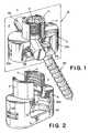
- FIG. 1is a perspective view of a bone screw apparatus embodiment of the present invention
- FIG. 2is a perspective view of a coupling element of the bone screw apparatus of FIG. 1 ;
- FIG. 3is an anterior perspective view of the coupling element of FIG. 2 ;
- FIG. 4is a perspective view of an optional locking wedge for use with the bone screw apparatus of FIG. 1 ;
- FIG. 5is a plan view of a polyaxial screw of the bone screw apparatus of FIG. 1 ;
- FIG. 6is an anterior perspective view of a another embodiment of a bone screw apparatus of the present invention.
- FIG. 7is a perspective view of a further embodiment of the present invention.
- FIG. 8is an anterior perspective view of yet another embodiment of a bone screw apparatus of the present invention.
- FIG. 9is an illustration of a bone screw system of the present invention affixed to bone.
- the term “anterior” and “posterior”mean nearer to the front or the back of the body respectively. “Proximal” and “distal” mean nearer and farther from the center of the body respectively. “Medial” and “lateral” mean nearer or farther from the median plane respectively.
- the median planeis an imaginary, vertical plane that divides the body into a right and left half.
- a coronal planeis an imaginary, vertical plane that divides the body into a front half and a back half.
- “Superior” and “inferior”mean above or below respectively. “Sagittal” means a side profile.
- the present inventionprovides for a bone screw apparatus, system, and method for attaching a connector to a vertebra.
- the present inventionprovides for a bone screw apparatus 1 that includes a coupling element 2 , a fixation element 8 , a connector 30 , a locking wedge 40 , and a bone screw 50 .
- the coupling element 2includes an upper housing 4 and a lower housing 6 .
- a fixation element 8 as shown in FIG. 1is inserted into the apparatus 1 .
- the coupling element 2can optionally be configured as a single housing only.
- the fixation elementis a locking screw 8 and the coupling element 2 has a connector 30 therethrough as shown in FIG. 1 .
- the upper housing 4 and lower housing 6 unitscan be an integral one-piece unit or separate units connected together by any acceptable means (e.g., taper lock, mechanical locking mechanism, screw, dovetail, bonding, and the like).
- the upper housing 4has a cross-sectional shape perpendicular to axis A that is generally circular in shape but can also be any shape consistent with the intended use, such as a square, rectangle, oval, or the like. Further, the outer cross-sectional shape can vary from the cross-sectional shape of hole 10 extending therethrough.
- the upper housing 4is configured to accommodate the fixation element 8 .
- the upper housing 4is configured to have a hole 10 that can receive and accommodate a locking screw 8 (e.g., a set screw). It is preferred that the interior surface 11 defining the hole 10 is threaded, but other embodiments such as snap-fit, cross-threading, interlocking, and dovetailing can also be used.
- the lower housing 6can be wider or narrower measured perpendicular to axis A in the longest dimension of the device than the upper housing 4 .
- the lower housing 6is wider than the upper housing 4 and is generally configured as illustrated in FIG. 2 and 3 .
- the shape of the lower housing 6can be any other shape consistent with the intended use, such as a cross-sectional shape perpendicular to axis A that is circular, oval, or square so long as it can accommodate a slot 12 .
- the lower housing 6includes a slot 12 as illustrated in FIG. 3 .
- the slot 12can be positioned at the base 14 of the lower housing 6 .
- the base 14can be integrally formed as part of the lower housing 14 , a separately formed and attached piece, or a prefabricated interchangeable insert having a slot 12 .
- the base 14has a posterior surface 16 (as shown in FIG. 2 ) and an anterior surface 18 .
- the slot 12is formed so as to extend between surfaces 16 and 18 and includes a plurality of slot positions 20 , including a center slot position 20 a .
- the slot 12can alternatively include at least two slot positions, or a smooth peripheral, oval shaped or capsule shaped slot (i.e., a continuous slot).
- the slot 12allows the coupling element 2 to be positioned more medially, laterally, superiorly, or inferiorly relative to the position of the bone screw 50 . This advantageously allows the surgeon to optimally position the bone screw 50 without being limited by the constraints of a connector's position.
- the slot 12includes five slot positions 20 and a center slot position 20 a positioned directly below the threaded hole 10 .
- the slot positions 20are circular in shape but can be any other shape consistent with the intended use.
- the slot positionsare overlapping and form notches 22 .
- the notches 22facilitate positioning of the bone screw 50 into a bone by helping to prevent the bone screw 50 from moving to another slot position and guiding the bone screw 50 as the screw is being drilled into the bone.
- the notches 22further provide for greater contact area between the bone screw 50 and the coupling element 2 , which improves the overall structural integrity of the bone screw apparatus 1 when in use.
- the slot positions 20 and generally the edge of the slot 20can optionally be configured to have or be contoured with a beveled edge 24 as shown in FIG. 3 or a round edge (not shown).
- the edge 24can be complementary in shape to that of the screw head 52 .
- the contoured edgefacilitates movement (e.g., polyaxial movement) of the bone screw 50 within the coupling element 2 due to its generally complementary configuration to that of the curvate polyaxial screw head 52 (as shown in FIG. 5 ) of the bone screw 50 .
- the lower housing 6can include an aperture 26 as shown in FIG. 1 .
- the aperture 26allows the placement of a connector, such as rod 30 , within the coupling element 2 such that the connector (e.g., rod 30 ) is generally centered within the coupling element 2 , allowing for greater stability when fastening the locking screw 8 into place.
- the aperture 26can be configured so as to allow the connector to be perpendicular to plane B or at an angle relative to plane B, as illustrated in FIG. 1 .
- the lower housing 6can also include a visibility hole 28 .
- the visibility hole 28advantageously allows the surgeon to be able to see the polyaxial screw 50 during assembly of the bone screw apparatus 1 .
- the lower housing 6can optionally include angled ridges 32 a , 32 b positioned on the interior surface of the lower housing 6 of coupling element 2 for mating with angled flats 49 a , 49 b of an optional locking wedge 40 (as shown in FIG. 4 and described below).
- the angled flats 49 a , 49 b of the locking wedge 40 and angled ridges 32 a , 32 bform a wedge for mating and securing locking wedge 40 into place.
- the angled ridges 32 a , 32 bcan be slightly steeper than the angled flats 49 a , 49 b .
- the angled flats 49 a , 49 bhelp locking wedge 40 remain level and parallel with the base 14 of the coupling element 2 , to facilitate maintaining the alignment of the rod 30 .
- the fixation elementis configured to be a locking screw 8 as shown in FIG. 1 .
- the fixation elementcan also be a cam lock, a taper lock, an interference fit, a locking tab, a tapered wedge, a locking collar, a dovetail, or any other configuration consistent with the intended use.
- the fixation elementcan be positioned anywhere within the coupling element 2 such that the fixation element provides a securing force to the bone screw apparatus 1 (e.g., secures the coupling element 2 , rod 30 , and the bone screw 50 in a fixed position).
- the fixation elementcan be in an upper housing 4 or the lower housing 2 of the coupling element. Examples of such fixation elements are readily known in the art and a detailed explanation of such fixation elements is not necessary for a complete understanding of the present invention.
- the present embodimentfurther includes a connector.
- the connectoris configured as a rod 30 .
- the connectorcan also be a cylindrical rod, a square rod, an oval rod, a rectangular rod, a hollow rod, or any other longitudinal member consistent with the intended use.
- the present embodimentcan optionally include a locking wedge 40 as configured and illustrated in FIG. 4 .
- the locking wedge 40includes an optional connector channel 42 , a tool hole 44 , and a concave channel 46 defined by the downwardly extending sides 48 of the locking wedge 40 .
- the locking wedge 40can optionally include angled flats 49 a , 49 b to mate with angled ridges 32 a , 32 b on the lower housing 6 of the coupling element as discussed above.
- the angle of the angled flats 49 a , 49 bcan be from 0 to about 89 degrees, and preferably about 35 to about 55 degrees.
- the locking wedge 40can be made from a metal, alloy, polymer, or any combination thereof.
- the connector channel 42is formed on the posterior side of the locking wedge 40 and is configured to cradle or support and preferably mate with the surfaces of the rod 30 as it extends or passes through the device.
- the connector channel 42can be indented into the locking wedge 40 as illustrated in FIG. 4 .
- the configuration of the connector channel 42allows the rod 30 to be positioned perpendicular to or at an angle relative to plane B, as shown in FIG. 1 .
- the tool hole 44is configured to be a circular through hole but can, without limitation, be any shaped through hole.
- the tool hole 44can be positioned at the center of the locking wedge 40 , which helps a surgeon better manipulate the bone screw 50 .
- the size of the tool hole 44is configured to accommodate a range of motion for a surgical tool, such as a screwdriver or drill (not shown), such that the screw head 52 (as shown in FIG. 5 ) can be accessed by the surgical tool even when the bone screw 50 is at its maximum angulation.
- a surgical toolsuch as a screwdriver or drill (not shown)
- the bone screw 50 of the present embodimentis illustrated in FIG. 5 .
- Bone screw designslike the surgical tools discussed above, are readily known in the art and a detailed explanation of them are not necessary for a complete understanding of the present invention.
- the present embodiment of the inventionis not limited to polyaxial screws but can alternatively include non-polyaxial screws such as a posted bone screws or posted/polyaxial bone screws.
- the bone screw 50includes a head 52 and a threaded shaft 54 .
- the head 52is configured to have a predominately curvate shape such as a spherical outer surface or a hemispherical shape.
- the head 52further includes at least one recess 56 positioned on the top of the bone screw 50 to receive the application of a torque driving tool, such as a screw driver or drill.
- the recess 56can alternatively be any configuration that cooperates with any suitable torque driving tool, such as a phillips head configuration, allen wrench, or the like.
- the size of the head 52 and diameter of the threaded shaftcan vary depending upon the individual circumstances and size requirements for a particular use or patient. As the size of the bone screw 50 changes, the size of other corresponding components of the bone screw apparatus 1 should change accordingly.
- the bone screw 50is adjustably positioned within the lower housing 6 with its head 52 positioned within the lower housing 6 and in one of the slot positions 20 .
- the spherical shape of the screw head 52allows the bone screw 50 to be angled relative to axis A.
- the locking wedge 40is positioned within the lower housing 6 such that the concave channel 46 contacts the screw head 52 .
- the rod 30is then positioned to extend through the coupling element 2 and in contact with or on the connector channel 42 .
- the shape of the connector channel 42allows the rod 30 to be either perpendicular to or at an angle relative to the direction of the concave channel 46 .
- the locking screw 8is then screwed (i.e.
- the locking screw 8As the locking screw 8 is screwed down, it pulls the coupling element 2 posteriorly. As the locking screw 8 is screwed down, it pushes anteriorly onto the rod 30 transmitting a securing force (e.g., an anteriorly directed force) onto the rod 30 .
- a securing forcee.g., an anteriorly directed force
- the locking screw 8supplies an anterior force (i.e., a securing force) to the rod 30 which further transmits a securing force onto the locking wedge 40 which, as a result, secures the coupling element 2 and the bone screw 50 in a fixed position.
- the anterior force of the locking screw 8 and the resulting posterior force of the coupling elementassembles the bone screw apparatus 1 into a secure and stable position regardless of which slot position 20 the bone screw 50 is located.
- the coupling element 2can be preassembled with the bone screw 50 , which is positioned loosely in a center slot position or the center of the slot 12 .
- Locking wedge 40can be positioned inside the coupling element 2 such that angled flats 49 a , 49 b lie loosely on top of angled ridges 32 a , 32 b of coupling element 2 .
- the concave channel 46 of locking wedge 48can contact the screw's head 52 as it is positioned in the coupling element 2 .
- a screw-driving tool(not shown) is then inserted through the coupling element 2 from above such that it passes through the upper housing 4 and through tool hole 44 of locking wedge 40 .
- the driving toolsecures bone screw 50 into the bone at a strategic place as determined by the surgeon.
- coupling element 2is able to move along a plane of the bone surface. That is, coupling element 2 is able to travel along the length of the slot 12 relative to the position of the bone screw 50 , and is able to rotate a full 360 degrees around the screw head 52 . Coupling element 2 can then be slid medio-laterally for optimal positioning, or rotated in the same plane if needed, so that upper housing 4 lines up with the rod 30 and the screw head 52 is positioned in one of the slot positions 20 .
- screw head 52is located in the proper slot position 20 , the surgeon then inserts rod 30 into the coupling element 2 via through hole 26 , wherein the rod 30 is positioned on connector channel 42 of locking wedge 40 .
- the surgeoncan then use the screw-driving tool to fasten locking screw 8 onto the upper housing 4 of coupling element 2 .
- Locking screw 8is then tightened or screwed down until locking wedge 40 engages the screw head 52 (e.g., by being compressed between rod 30 and the screw head 52 ).
- Coupling element 2is pulled upwards as locking screw 8 is tightened so that screw head 52 is secured inside slot position 20 of slot 12 .
- locking screw 8can be unfastened and rod 30 removed.
- Locking wedge 40is loosened by insertion of a tool (not shown) through tool hole 44 .
- a gripping tool(not shown) may then be used to push down on coupling element 2 and the coupling element 2 slid such that screw head 52 can be located in a center slot position, allowing for the screw driving tool to access and loosen the bone screw 50 .
- FIG. 6illustrates another embodiment of the present invention.
- the bone screw apparatus 100includes a coupling element 102 having a continuous slot 104 .
- FIG. 7illustrates a further embodiment of the present invention.
- the bone screw apparatus 200includes a coupling element 202 having two bone screws 204 a , 204 b for screwing into a bone.
- FIG. 8illustrates yet another embodiment of the present invention.
- bone screw apparatus 300includes a coupling element 302 having a slot 304 with an anterior surface 306 and a posterior surface 308 (not shown).
- the slot 304includes five slot positions 310 .
- the slot 304includes a continuous beveled edge 312 configured to have three diameters D 1 , D 2 , and D 3 positioned along the edge between surfaces 306 , 308 .
- D 1is the largest diameter adjacent the posterior surface 308 .
- D 1can be 3.6 mm, which is larger than the diameter of the polyaxial screw head and allows the maximum amount of motion for the bone screw before it is secured into the bone.
- the beveled edge 312then tapers down into a second diameter D 2 that measures, for example, 3.4 mm.
- This diameter D 2which is slightly smaller than that of the diameter of the polyaxial screw head, helps prevents the screw head from slipping through the slot positions 310 .
- Located below diameter D 2is diameter D 3 .
- the diameter D 3is 3.5 mm that allows the screw to retain about 30 degrees angulation relative to the vertical. To increase this angulation, the diameter D 3 can be increased.
- the present inventionalso provides for a bone screw system 400 as shown in FIG. 9 .
- the bone screw system 400includes a least two bone screw apparatuses 402 a , 402 b and a connector 404 .
- Each bone screw apparatusfor example 402 a , includes a coupling element having an aperture, a fixation element, an optional locking wedge, and at least one bone screw 406 .
- the connector 404is attached to and extends through at least two bone screw apparatuses 402 a , 402 b that are each independently affixed to a bone.
- the present inventionfurther provides for a method for placing and aligning a bone screw system (as describe above) in bone.
- the methodincludes positioning a bone screw in a slot of a coupling element (as described in any of the above embodiments), inserting the bone screw into the bone, repositioning the coupling element relative to the bone screw, and securing the alignment and position of the coupling element, and bone screw.
- the methodcan further include positioning a connector (as described in any of the above embodiments) through the coupling element, and securing the alignment and position of the connector, coupling element, and bone screw.
- the present inventionalso provides for a method for aligning bones.
- the methodincludes providing a bone screw system.
- the bone screw systemincludes at least two bone screw apparatuses that each include a coupling element having a connector therethrough and a slot, and a bone screw positioned within the slot, wherein the connector transmits a securing force securing the coupling element and bone screw in a fixed position.
- the present inventionadvantageously allows for additional positioning freedom between a bone screw and a connector in multiple degrees of freedom including the medial, lateral, superior, and inferior directions.
Landscapes
- Health & Medical Sciences (AREA)
- Orthopedic Medicine & Surgery (AREA)
- Life Sciences & Earth Sciences (AREA)
- Neurology (AREA)
- Surgery (AREA)
- Heart & Thoracic Surgery (AREA)
- Engineering & Computer Science (AREA)
- Biomedical Technology (AREA)
- Nuclear Medicine, Radiotherapy & Molecular Imaging (AREA)
- Medical Informatics (AREA)
- Molecular Biology (AREA)
- Animal Behavior & Ethology (AREA)
- General Health & Medical Sciences (AREA)
- Public Health (AREA)
- Veterinary Medicine (AREA)
- Surgical Instruments (AREA)
Abstract
Description
Claims (21)
Priority Applications (2)
| Application Number | Priority Date | Filing Date | Title |
|---|---|---|---|
| US11/510,008US7955358B2 (en) | 2005-09-19 | 2006-08-25 | Bone screw apparatus, system and method |
| US13/911,397USRE46115E1 (en) | 2005-09-19 | 2013-06-06 | Bone screw apparatus, system and method |
Applications Claiming Priority (2)
| Application Number | Priority Date | Filing Date | Title |
|---|---|---|---|
| US71843405P | 2005-09-19 | 2005-09-19 | |
| US11/510,008US7955358B2 (en) | 2005-09-19 | 2006-08-25 | Bone screw apparatus, system and method |
Related Child Applications (1)
| Application Number | Title | Priority Date | Filing Date |
|---|---|---|---|
| US13/911,397ReissueUSRE46115E1 (en) | 2005-09-19 | 2013-06-06 | Bone screw apparatus, system and method |
Publications (2)
| Publication Number | Publication Date |
|---|---|
| US20070093819A1 US20070093819A1 (en) | 2007-04-26 |
| US7955358B2true US7955358B2 (en) | 2011-06-07 |
Family
ID=37986256
Family Applications (2)
| Application Number | Title | Priority Date | Filing Date |
|---|---|---|---|
| US11/510,008CeasedUS7955358B2 (en) | 2005-09-19 | 2006-08-25 | Bone screw apparatus, system and method |
| US13/911,397Expired - Fee RelatedUSRE46115E1 (en) | 2005-09-19 | 2013-06-06 | Bone screw apparatus, system and method |
Family Applications After (1)
| Application Number | Title | Priority Date | Filing Date |
|---|---|---|---|
| US13/911,397Expired - Fee RelatedUSRE46115E1 (en) | 2005-09-19 | 2013-06-06 | Bone screw apparatus, system and method |
Country Status (1)
| Country | Link |
|---|---|
| US (2) | US7955358B2 (en) |
Cited By (21)
| Publication number | Priority date | Publication date | Assignee | Title |
|---|---|---|---|---|
| US20110112578A1 (en)* | 2009-11-09 | 2011-05-12 | Ebi, Llc | Multiplanar bone anchor system |
| US8894657B2 (en) | 2004-02-27 | 2014-11-25 | Roger P. Jackson | Tool system for dynamic spinal implants |
| US9044272B2 (en) | 2009-11-09 | 2015-06-02 | Ebi, Llc | Multiplanar bone anchor system |
| US9050139B2 (en) | 2004-02-27 | 2015-06-09 | Roger P. Jackson | Orthopedic implant rod reduction tool set and method |
| US9055978B2 (en) | 2004-02-27 | 2015-06-16 | Roger P. Jackson | Orthopedic implant rod reduction tool set and method |
| US9060813B1 (en) | 2008-02-29 | 2015-06-23 | Nuvasive, Inc. | Surgical fixation system and related methods |
| US20150182261A1 (en)* | 2013-12-31 | 2015-07-02 | Blackstone Medical, Inc. | Translational pedicle screw systems |
| US9387013B1 (en) | 2011-03-01 | 2016-07-12 | Nuvasive, Inc. | Posterior cervical fixation system |
| USRE46115E1 (en) | 2005-09-19 | 2016-08-23 | Ebi, Llc | Bone screw apparatus, system and method |
| US9532815B2 (en) | 2004-02-27 | 2017-01-03 | Roger P. Jackson | Spinal fixation tool set and method |
| US20170290608A1 (en)* | 2016-01-22 | 2017-10-12 | Spinal Usa, Inc. | Spinal fixation systems and methods |
| USD799949S1 (en) | 2007-10-24 | 2017-10-17 | Nuvasive, Inc. | Favored angle screw |
| US9987047B2 (en) | 2013-10-07 | 2018-06-05 | Spine Wave, Inc. | Translating polyaxial screw |
| US10034691B1 (en) | 2015-12-03 | 2018-07-31 | Nuvasive, Inc. | Bone anchor |
| US10039577B2 (en) | 2004-11-23 | 2018-08-07 | Roger P Jackson | Bone anchor receiver with horizontal radiused tool attachment structures and parallel planar outer surfaces |
| US20190038323A1 (en)* | 2015-08-31 | 2019-02-07 | Bpath | Vertebral implant, method for the placement of such an implant and tool for the placement of the implant |
| US10299839B2 (en) | 2003-12-16 | 2019-05-28 | Medos International Sárl | Percutaneous access devices and bone anchor assemblies |
| US10485588B2 (en) | 2004-02-27 | 2019-11-26 | Nuvasive, Inc. | Spinal fixation tool attachment structure |
| US11147597B2 (en) | 2004-02-27 | 2021-10-19 | Roger P Jackson | Dynamic spinal stabilization assemblies, tool set and method |
| US11241261B2 (en) | 2005-09-30 | 2022-02-08 | Roger P Jackson | Apparatus and method for soft spinal stabilization using a tensionable cord and releasable end structure |
| US11419642B2 (en) | 2003-12-16 | 2022-08-23 | Medos International Sarl | Percutaneous access devices and bone anchor assemblies |
Families Citing this family (75)
| Publication number | Priority date | Publication date | Assignee | Title |
|---|---|---|---|---|
| US7833250B2 (en) | 2004-11-10 | 2010-11-16 | Jackson Roger P | Polyaxial bone screw with helically wound capture connection |
| US8353932B2 (en) | 2005-09-30 | 2013-01-15 | Jackson Roger P | Polyaxial bone anchor assembly with one-piece closure, pressure insert and plastic elongate member |
| US8292926B2 (en) | 2005-09-30 | 2012-10-23 | Jackson Roger P | Dynamic stabilization connecting member with elastic core and outer sleeve |
| US10258382B2 (en) | 2007-01-18 | 2019-04-16 | Roger P. Jackson | Rod-cord dynamic connection assemblies with slidable bone anchor attachment members along the cord |
| US10729469B2 (en) | 2006-01-09 | 2020-08-04 | Roger P. Jackson | Flexible spinal stabilization assembly with spacer having off-axis core member |
| AR038680A1 (en) | 2002-02-19 | 2005-01-26 | Synthes Ag | INTERVERTEBRAL IMPLANT |
| US8876868B2 (en) | 2002-09-06 | 2014-11-04 | Roger P. Jackson | Helical guide and advancement flange with radially loaded lip |
| WO2006052796A2 (en) | 2004-11-10 | 2006-05-18 | Jackson Roger P | Helical guide and advancement flange with break-off extensions |
| CA2515247C (en) | 2003-02-06 | 2010-10-05 | Synthes (U.S.A.) | Intervertebral implant |
| US6716214B1 (en) | 2003-06-18 | 2004-04-06 | Roger P. Jackson | Polyaxial bone screw with spline capture connection |
| US7377923B2 (en) | 2003-05-22 | 2008-05-27 | Alphatec Spine, Inc. | Variable angle spinal screw assembly |
| US8137386B2 (en) | 2003-08-28 | 2012-03-20 | Jackson Roger P | Polyaxial bone screw apparatus |
| US7766915B2 (en) | 2004-02-27 | 2010-08-03 | Jackson Roger P | Dynamic fixation assemblies with inner core and outer coil-like member |
| US8377102B2 (en) | 2003-06-18 | 2013-02-19 | Roger P. Jackson | Polyaxial bone anchor with spline capture connection and lower pressure insert |
| US8926670B2 (en) | 2003-06-18 | 2015-01-06 | Roger P. Jackson | Polyaxial bone screw assembly |
| US7967850B2 (en) | 2003-06-18 | 2011-06-28 | Jackson Roger P | Polyaxial bone anchor with helical capture connection, insert and dual locking assembly |
| US7776067B2 (en) | 2005-05-27 | 2010-08-17 | Jackson Roger P | Polyaxial bone screw with shank articulation pressure insert and method |
| US8398682B2 (en) | 2003-06-18 | 2013-03-19 | Roger P. Jackson | Polyaxial bone screw assembly |
| US8257398B2 (en) | 2003-06-18 | 2012-09-04 | Jackson Roger P | Polyaxial bone screw with cam capture |
| US7527638B2 (en) | 2003-12-16 | 2009-05-05 | Depuy Spine, Inc. | Methods and devices for minimally invasive spinal fixation element placement |
| US7651502B2 (en) | 2004-09-24 | 2010-01-26 | Jackson Roger P | Spinal fixation tool set and method for rod reduction and fastener insertion |
| US8926672B2 (en) | 2004-11-10 | 2015-01-06 | Roger P. Jackson | Splay control closure for open bone anchor |
| US9216041B2 (en) | 2009-06-15 | 2015-12-22 | Roger P. Jackson | Spinal connecting members with tensioned cords and rigid sleeves for engaging compression inserts |
| US8308782B2 (en) | 2004-11-23 | 2012-11-13 | Jackson Roger P | Bone anchors with longitudinal connecting member engaging inserts and closures for fixation and optional angulation |
| US9980753B2 (en) | 2009-06-15 | 2018-05-29 | Roger P Jackson | pivotal anchor with snap-in-place insert having rotation blocking extensions |
| US8444681B2 (en) | 2009-06-15 | 2013-05-21 | Roger P. Jackson | Polyaxial bone anchor with pop-on shank, friction fit retainer and winged insert |
| US7875065B2 (en) | 2004-11-23 | 2011-01-25 | Jackson Roger P | Polyaxial bone screw with multi-part shank retainer and pressure insert |
| US9168069B2 (en) | 2009-06-15 | 2015-10-27 | Roger P. Jackson | Polyaxial bone anchor with pop-on shank and winged insert with lower skirt for engaging a friction fit retainer |
| US7901437B2 (en) | 2007-01-26 | 2011-03-08 | Jackson Roger P | Dynamic stabilization member with molded connection |
| US10076361B2 (en) | 2005-02-22 | 2018-09-18 | Roger P. Jackson | Polyaxial bone screw with spherical capture, compression and alignment and retention structures |
| US8105368B2 (en) | 2005-09-30 | 2012-01-31 | Jackson Roger P | Dynamic stabilization connecting member with slitted core and outer sleeve |
| US7833252B2 (en) | 2006-01-27 | 2010-11-16 | Warsaw Orthopedic, Inc. | Pivoting joints for spinal implants including designed resistance to motion and methods of use |
| US8057519B2 (en)* | 2006-01-27 | 2011-11-15 | Warsaw Orthopedic, Inc. | Multi-axial screw assembly |
| US7722652B2 (en) | 2006-01-27 | 2010-05-25 | Warsaw Orthopedic, Inc. | Pivoting joints for spinal implants including designed resistance to motion and methods of use |
| EP1988855A2 (en) | 2006-02-27 | 2008-11-12 | Synthes GmbH | Intervertebral implant with fixation geometry |
| US9867640B2 (en) | 2006-12-07 | 2018-01-16 | Nexus Spine, LLC | Press-on pedicle screw assembly |
| US8366745B2 (en) | 2007-05-01 | 2013-02-05 | Jackson Roger P | Dynamic stabilization assembly having pre-compressed spacers with differential displacements |
| US8475498B2 (en) | 2007-01-18 | 2013-07-02 | Roger P. Jackson | Dynamic stabilization connecting member with cord connection |
| US10792074B2 (en) | 2007-01-22 | 2020-10-06 | Roger P. Jackson | Pivotal bone anchor assemly with twist-in-place friction fit insert |
| US10383660B2 (en) | 2007-05-01 | 2019-08-20 | Roger P. Jackson | Soft stabilization assemblies with pretensioned cords |
| US8979904B2 (en) | 2007-05-01 | 2015-03-17 | Roger P Jackson | Connecting member with tensioned cord, low profile rigid sleeve and spacer with torsion control |
| JP2011502708A (en) | 2007-11-16 | 2011-01-27 | ジンテス ゲゼルシャフト ミット ベシュレンクテル ハフツング | Low profile intervertebral implant |
| AU2010260521C1 (en) | 2008-08-01 | 2013-08-01 | Roger P. Jackson | Longitudinal connecting member with sleeved tensioned cords |
| US20100087873A1 (en)* | 2008-10-06 | 2010-04-08 | Warsaw Orthopedics, Inc. | Surgical Connectors for Attaching an Elongated Member to a Bone |
| CN102256570B (en) | 2008-11-07 | 2015-09-02 | 斯恩蒂斯有限公司 | Spacer and connecting plate assembly between vertebral bodies |
| US9668771B2 (en) | 2009-06-15 | 2017-06-06 | Roger P Jackson | Soft stabilization assemblies with off-set connector |
| US11229457B2 (en) | 2009-06-15 | 2022-01-25 | Roger P. Jackson | Pivotal bone anchor assembly with insert tool deployment |
| US8998959B2 (en) | 2009-06-15 | 2015-04-07 | Roger P Jackson | Polyaxial bone anchors with pop-on shank, fully constrained friction fit retainer and lock and release insert |
| CN103826560A (en) | 2009-06-15 | 2014-05-28 | 罗杰.P.杰克逊 | Polyaxial Bone Anchor with Socket Stem and Winged Inserts with Friction Fit Compression Collars |
| TR200905304A2 (en)* | 2009-07-08 | 2011-01-21 | Tasarim Med Tibbi̇ Mamuller San.Ve Ti̇caret Li̇mi̇ted Şi̇rketi̇ | Internally locked double sacrum screw system. |
| EP2485654B1 (en) | 2009-10-05 | 2021-05-05 | Jackson P. Roger | Polyaxial bone anchor with non-pivotable retainer and pop-on shank, some with friction fit |
| US12383311B2 (en) | 2010-05-14 | 2025-08-12 | Roger P. Jackson | Pivotal bone anchor assembly and method for use thereof |
| AU2011299558A1 (en) | 2010-09-08 | 2013-05-02 | Roger P. Jackson | Dynamic stabilization members with elastic and inelastic sections |
| AU2011324058A1 (en) | 2010-11-02 | 2013-06-20 | Roger P. Jackson | Polyaxial bone anchor with pop-on shank and pivotable retainer |
| US9241809B2 (en)* | 2010-12-21 | 2016-01-26 | DePuy Synthes Products, Inc. | Intervertebral implants, systems, and methods of use |
| WO2012088238A2 (en) | 2010-12-21 | 2012-06-28 | Synthes Usa, Llc | Intervertebral implants, systems, and methods of use |
| JP5865479B2 (en) | 2011-03-24 | 2016-02-17 | ロジャー・ピー・ジャクソン | Multiaxial bone anchor with compound joint and pop-mounted shank |
| ES2546157T3 (en)* | 2011-10-27 | 2015-09-21 | Biedermann Technologies Gmbh & Co. Kg | Wide angle polyaxial bone anchoring device |
| US8911479B2 (en) | 2012-01-10 | 2014-12-16 | Roger P. Jackson | Multi-start closures for open implants |
| US9427260B2 (en) | 2012-03-01 | 2016-08-30 | Globus Medical, Inc. | Closed-head polyaxial and monaxial screws |
| US10405893B2 (en) | 2012-07-12 | 2019-09-10 | DePuy Synthes Products, Inc. | Device, kit and method for correction of spinal deformity |
| DE102012016294B4 (en)* | 2012-08-16 | 2014-02-27 | Spontech Spine Intelligence Group Ag | Polyaxial connector for spinal fixation systems and spine fixation system |
| US8911478B2 (en) | 2012-11-21 | 2014-12-16 | Roger P. Jackson | Splay control closure for open bone anchor |
| US10058354B2 (en) | 2013-01-28 | 2018-08-28 | Roger P. Jackson | Pivotal bone anchor assembly with frictional shank head seating surfaces |
| US8852239B2 (en) | 2013-02-15 | 2014-10-07 | Roger P Jackson | Sagittal angle screw with integral shank and receiver |
| US9566092B2 (en) | 2013-10-29 | 2017-02-14 | Roger P. Jackson | Cervical bone anchor with collet retainer and outer locking sleeve |
| US9717533B2 (en) | 2013-12-12 | 2017-08-01 | Roger P. Jackson | Bone anchor closure pivot-splay control flange form guide and advancement structure |
| US9451993B2 (en) | 2014-01-09 | 2016-09-27 | Roger P. Jackson | Bi-radial pop-on cervical bone anchor |
| US9597119B2 (en) | 2014-06-04 | 2017-03-21 | Roger P. Jackson | Polyaxial bone anchor with polymer sleeve |
| US10064658B2 (en) | 2014-06-04 | 2018-09-04 | Roger P. Jackson | Polyaxial bone anchor with insert guides |
| US9867718B2 (en) | 2014-10-22 | 2018-01-16 | DePuy Synthes Products, Inc. | Intervertebral implants, systems, and methods of use |
| US10070897B1 (en) | 2017-10-10 | 2018-09-11 | Spine Wave, Inc. | Translational posterior cervical polyaxial screw |
| EP4114292B1 (en)* | 2020-03-03 | 2025-06-11 | Inno4Spine AG | Spinal bone fastener assembly |
| US11589904B2 (en)* | 2021-03-31 | 2023-02-28 | Bret Michael Berry | Pedicle screw with detachable polyaxial head |
| US20230301689A1 (en)* | 2022-03-25 | 2023-09-28 | Globus Medical, Inc. | Stabilizing bones using screws and rods |
Citations (31)
| Publication number | Priority date | Publication date | Assignee | Title |
|---|---|---|---|---|
| US5312404A (en)* | 1990-07-24 | 1994-05-17 | Acromed Corporation | Spinal column retaining apparatus |
| US5352224A (en)* | 1990-11-29 | 1994-10-04 | Howmedica Gmbh | Correction implant for the human vertebral column |
| US5360431A (en)* | 1990-04-26 | 1994-11-01 | Cross Medical Products | Transpedicular screw system and method of use |
| US5584834A (en) | 1995-07-13 | 1996-12-17 | Fastenetix, L.L.C. | Polyaxial locking screw and coupling element assembly for use with side loading rod fixation apparatus |
| US5669911A (en) | 1995-04-13 | 1997-09-23 | Fastenetix, L.L.C. | Polyaxial pedicle screw |
| US6010503A (en) | 1998-04-03 | 2000-01-04 | Spinal Innovations, Llc | Locking mechanism |
| US6053917A (en) | 1996-09-24 | 2000-04-25 | Sdgi Holdings, Inc. | Multi-axial bone screw assembly |
| US20020183747A1 (en)* | 2001-05-30 | 2002-12-05 | Merries International Inc. | Spinal fixation apparatus |
| US20030167058A1 (en) | 2002-03-01 | 2003-09-04 | Endius Incorporated | Apparatus for connecting a longitudinal member to a bone portion |
| US6660005B2 (en) | 2000-12-27 | 2003-12-09 | Kyocera Corporation | Vertebra correcting and fixing device |
| US6682529B2 (en)* | 2002-06-11 | 2004-01-27 | Stahurski Consulting, Inc. | Connector assembly with multidimensional accommodation and associated method |
| US6716214B1 (en) | 2003-06-18 | 2004-04-06 | Roger P. Jackson | Polyaxial bone screw with spline capture connection |
| US20040138660A1 (en) | 2003-01-10 | 2004-07-15 | Serhan Hassan A. | Locking cap assembly for spinal fixation instrumentation |
| US20040143265A1 (en) | 2002-10-30 | 2004-07-22 | Landry Michael E. | Spinal stabilization systems and methods using minimally invasive surgical procedures |
| US20040153068A1 (en) | 2003-02-05 | 2004-08-05 | Pioneer Laboratories, Inc. | Low profile spinal fixation system |
| US20040158247A1 (en)* | 2003-02-07 | 2004-08-12 | Arthit Sitiso | Polyaxial pedicle screw system |
| US20040162558A1 (en) | 2003-02-18 | 2004-08-19 | Hegde Sajan K. | Spinal plate having an integral rod connector portion |
| US6780186B2 (en) | 1995-04-13 | 2004-08-24 | Third Millennium Engineering Llc | Anterior cervical plate having polyaxial locking screws and sliding coupling elements |
| US20040204771A1 (en) | 2003-04-11 | 2004-10-14 | Swanson Verner M. | Adapter bracket for prostheses, method and apparatus for forming prosthetic device with transfer of proper alignment |
| US20040215190A1 (en)* | 2003-04-25 | 2004-10-28 | Nguyen Thanh V. | System and method for minimally invasive posterior fixation |
| US20040236330A1 (en)* | 2003-05-22 | 2004-11-25 | Thomas Purcell | Variable angle spinal screw assembly |
| US20040243126A1 (en) | 2001-09-14 | 2004-12-02 | Stryker Spine | Methods for stabilizing bone using spinal fixation devices |
| US20040267264A1 (en) | 2003-06-27 | 2004-12-30 | Konieczynski David D. | Polyaxial bone screw |
| US20050010221A1 (en) | 2003-07-07 | 2005-01-13 | Dalton Brian E. | Spinal stabilization implant and method of application |
| US6860884B2 (en) | 2001-08-01 | 2005-03-01 | Showa Ika Kohgyo Co., Ltd. | Implant for bone connector |
| US20050080415A1 (en)* | 2003-10-14 | 2005-04-14 | Keyer Thomas R. | Polyaxial bone anchor and method of spinal fixation |
| US20050131410A1 (en)* | 2003-12-11 | 2005-06-16 | A-Spine Holding Group Corp. | Rotary device for retrieving spinal column under treatment |
| US20050187548A1 (en)* | 2004-01-13 | 2005-08-25 | Butler Michael S. | Pedicle screw constructs for spine fixation systems |
| US20050261687A1 (en)* | 2004-04-20 | 2005-11-24 | Laszlo Garamszegi | Pedicle screw assembly |
| US20060025767A1 (en)* | 2002-11-04 | 2006-02-02 | Khalili Farid B | Orthopedic rod system |
| US7235075B1 (en)* | 2002-05-21 | 2007-06-26 | Peter Metz-Stavenhagen | Anchoring element for securing a rod on a vertebra |
Family Cites Families (120)
| Publication number | Priority date | Publication date | Assignee | Title |
|---|---|---|---|---|
| DE3936703A1 (en) | 1989-11-03 | 1991-05-08 | Lutz Biedermann | BONE SCREW |
| CA2035348C (en) | 1990-02-08 | 2000-05-16 | Jean-Louis Vignaud | Adjustable fastening device with spinal osteosynthesis rods |
| US5291075A (en) | 1990-10-01 | 1994-03-01 | Motorola, Inc. | Fault detection circuit |
| GB9113578D0 (en) | 1991-06-24 | 1991-08-14 | Howmedica | Intramedullary intertrochanteric fracture fixation appliance |
| WO1995013755A1 (en) | 1993-11-19 | 1995-05-26 | Cross Medical Products, Inc. | Rod anchor seat having sliding closure member |
| US5466237A (en) | 1993-11-19 | 1995-11-14 | Cross Medical Products, Inc. | Variable locking stabilizer anchor seat and screw |
| DE9402839U1 (en) | 1994-02-22 | 1994-04-14 | Howmedica GmbH, 24232 Schönkirchen | Device for setting up a spine with damaged vertebrae |
| US5499983A (en) | 1994-02-23 | 1996-03-19 | Smith & Nephew Richards, Inc. | Variable angle spinal screw |
| FR2731344B1 (en)* | 1995-03-06 | 1997-08-22 | Dimso Sa | SPINAL INSTRUMENTATION ESPECIALLY FOR A ROD |
| DE19509332C1 (en) | 1995-03-15 | 1996-08-14 | Harms Juergen | Anchoring element |
| US5520690A (en) | 1995-04-13 | 1996-05-28 | Errico; Joseph P. | Anterior spinal polyaxial locking screw plate assembly |
| US5882350A (en) | 1995-04-13 | 1999-03-16 | Fastenetix, Llc | Polyaxial pedicle screw having a threaded and tapered compression locking mechanism |
| ES2211964T3 (en) | 1995-07-13 | 2004-07-16 | Fastenetix, L.L.C. | MECHANISMS OF POLIAXIAL LOCK. |
| US5713900A (en) | 1996-05-31 | 1998-02-03 | Acromed Corporation | Apparatus for retaining bone portions in a desired spatial relationship |
| AUPO204596A0 (en) | 1996-08-30 | 1996-09-26 | Bhp Steel (Jla) Pty Limited | Block feeding means |
| ES2191775T3 (en) | 1996-12-12 | 2003-09-16 | Synthes Ag | DEVICE FOR CONNECTING A LONGITUDINAL SUPPORT WITH A PEDICULAR SCREW. |
| US5741256A (en) | 1997-01-13 | 1998-04-21 | Synthes (U.S.A.) | Helical osteosynthetic implant |
| US6248105B1 (en) | 1997-05-17 | 2001-06-19 | Synthes (U.S.A.) | Device for connecting a longitudinal support with a pedicle screw |
| DE19720782B4 (en) | 1997-05-17 | 2004-12-09 | Synthes Ag Chur, Chur | Device for connecting a side member to a pedicle screw |
| DE29710484U1 (en) | 1997-06-16 | 1998-10-15 | Howmedica GmbH, 24232 Schönkirchen | Receiving part for a holding component of a spinal implant |
| AU731222B2 (en) | 1997-08-25 | 2001-03-29 | Chr. Hansen A/S | Dairy starter culture delivery system and use hereof |
| US6565565B1 (en) | 1998-06-17 | 2003-05-20 | Howmedica Osteonics Corp. | Device for securing spinal rods |
| US6090111A (en) | 1998-06-17 | 2000-07-18 | Surgical Dynamics, Inc. | Device for securing spinal rods |
| FR2781663B1 (en)* | 1998-07-30 | 2000-10-13 | Materiel Orthopedique En Abreg | SPINAL OSTEOSYNTHESIS DEVICE |
| US6110172A (en) | 1998-07-31 | 2000-08-29 | Jackson; Roger P. | Closure system for open ended osteosynthesis apparatus |
| PT1117336E (en) | 1998-09-29 | 2004-10-29 | Synthes Ag | DEVICE FOR CONNECTING A LONGITUDINAL SUPPORT TO A BONUS FIXATION MEANS |
| US6296642B1 (en) | 1998-11-09 | 2001-10-02 | Sdgi Holdings, Inc. | Reverse angle thread for preventing splaying in medical devices |
| US6315779B1 (en) | 1999-04-16 | 2001-11-13 | Sdgi Holdings, Inc. | Multi-axial bone anchor system |
| US6273888B1 (en) | 1999-05-28 | 2001-08-14 | Sdgi Holdings, Inc. | Device and method for selectively preventing the locking of a shape-memory alloy coupling system |
| US6254602B1 (en) | 1999-05-28 | 2001-07-03 | Sdgi Holdings, Inc. | Advanced coupling device using shape-memory technology |
| FR2794637B1 (en) | 1999-06-14 | 2001-12-28 | Scient X | IMPLANT FOR OSTEOSYNTHESIS DEVICE, ESPECIALLY OF THE RACHIS |
| DE19936286C2 (en) | 1999-08-02 | 2002-01-17 | Lutz Biedermann | bone screw |
| US6280442B1 (en) | 1999-09-01 | 2001-08-28 | Sdgi Holdings, Inc. | Multi-axial bone screw assembly |
| AU1493301A (en) | 1999-09-27 | 2001-04-30 | Blackstone Medical, Inc. | A surgical screw system and related methods |
| US6443953B1 (en) | 2000-02-08 | 2002-09-03 | Cross Medical Products, Inc. | Self-aligning cap nut for use with a spinal rod anchor |
| US6565566B1 (en) | 2000-03-22 | 2003-05-20 | Spinal Concepts, Inc. | Sacral screw assembly and method |
| US6251112B1 (en) | 2000-04-18 | 2001-06-26 | Roger P. Jackson | Thin profile closure cap for open ended medical implant |
| US6440132B1 (en) | 2000-05-24 | 2002-08-27 | Roger P. Jackson | Open head bone screw closure with threaded boss |
| AU2001270720B2 (en) | 2000-06-30 | 2007-02-08 | Henry Graf | Intervertebral linking device |
| JP4278289B2 (en) | 2000-07-27 | 2009-06-10 | 有限会社ケイオーアイ | Intramedullary nail |
| US6755829B1 (en) | 2000-09-22 | 2004-06-29 | Depuy Acromed, Inc. | Lock cap anchor assembly for orthopaedic fixation |
| US6685705B1 (en) | 2000-10-23 | 2004-02-03 | Sdgi Holdings, Inc. | Six-axis and seven-axis adjustable connector |
| DE10055888C1 (en) | 2000-11-10 | 2002-04-25 | Biedermann Motech Gmbh | Bone screw, has connector rod receiving part with unsymmetrically arranged end bores |
| US6443954B1 (en) | 2001-04-24 | 2002-09-03 | Dale G. Bramlet | Femoral nail intramedullary system |
| US6478798B1 (en) | 2001-05-17 | 2002-11-12 | Robert S. Howland | Spinal fixation apparatus and methods for use |
| US6520963B1 (en) | 2001-08-13 | 2003-02-18 | Mckinley Lawrence M. | Vertebral alignment and fixation assembly |
| US6652526B1 (en) | 2001-10-05 | 2003-11-25 | Ruben P. Arafiles | Spinal stabilization rod fastener |
| WO2003047622A1 (en) | 2001-11-30 | 2003-06-12 | Jun Nishihira | Remedies for multiple sclerosis |
| US7306602B2 (en) | 2002-10-31 | 2007-12-11 | Depuy Actomed, Inc. | Snap-in washers and assemblies thereof |
| FR2847152B1 (en) | 2002-11-19 | 2005-02-18 | Eurosurgical | VERTEBRAL ANCHORING DEVICE AND ITS LOCKING DEVICE ON A POLY AXIAL SCREW |
| FR2855392B1 (en) | 2003-05-28 | 2005-08-05 | Spinevision | CONNECTION DEVICE FOR SPINAL OSTESYNTHESIS |
| US7776067B2 (en) | 2005-05-27 | 2010-08-17 | Jackson Roger P | Polyaxial bone screw with shank articulation pressure insert and method |
| US7322981B2 (en) | 2003-08-28 | 2008-01-29 | Jackson Roger P | Polyaxial bone screw with split retainer ring |
| US7967850B2 (en) | 2003-06-18 | 2011-06-28 | Jackson Roger P | Polyaxial bone anchor with helical capture connection, insert and dual locking assembly |
| US7731734B2 (en) | 2003-06-27 | 2010-06-08 | Medicrea Technologies | Vertebral osteosynthesis equipment |
| AU2004266737B2 (en) | 2003-08-20 | 2010-05-13 | Warsaw Orthopedic, Inc. | Multi-axial orthopedic device and system, e.g. for spinal surgery |
| US20050055024A1 (en) | 2003-09-08 | 2005-03-10 | James Anthony H. | Orthopaedic implant and screw assembly |
| WO2005065397A2 (en) | 2003-12-30 | 2005-07-21 | Depuy Spine Sarl | Bone anchor assemblies |
| US8048101B2 (en) | 2004-02-25 | 2011-11-01 | Femasys Inc. | Methods and devices for conduit occlusion |
| DE102004010382B4 (en) | 2004-03-03 | 2006-04-20 | Biedermann Motech Gmbh | Bone anchoring element for anchoring in a bone or in a vertebra and its use in a stabilizing device |
| DE102004010380A1 (en) | 2004-03-03 | 2005-09-22 | Biedermann Motech Gmbh | Anchoring element and stabilizing device for the dynamic stabilization of vertebrae or bones with such an anchoring element |
| US7648520B2 (en) | 2004-04-16 | 2010-01-19 | Kyphon Sarl | Pedicle screw assembly |
| US7850719B2 (en) | 2004-05-26 | 2010-12-14 | Warsaw Orthopedic, Inc. | Spinal implant apparatus |
| US7559943B2 (en) | 2004-06-09 | 2009-07-14 | Zimmer Spine, Inc. | Spinal fixation device with internal drive structure |
| US7857834B2 (en) | 2004-06-14 | 2010-12-28 | Zimmer Spine, Inc. | Spinal implant fixation assembly |
| US7264621B2 (en) | 2004-06-17 | 2007-09-04 | Sdgi Holdings, Inc. | Multi-axial bone attachment assembly |
| US7572279B2 (en) | 2004-11-10 | 2009-08-11 | Jackson Roger P | Polyaxial bone screw with discontinuous helically wound capture connection |
| US7875065B2 (en) | 2004-11-23 | 2011-01-25 | Jackson Roger P | Polyaxial bone screw with multi-part shank retainer and pressure insert |
| US7578833B2 (en)* | 2004-12-13 | 2009-08-25 | Dr. Robert S. Bray, Jr. | Bone fastener assembly for bone retention apparatus |
| US7704270B2 (en) | 2004-12-22 | 2010-04-27 | Stryker Spine | Variable offset connectors and bone fixation methods |
| US7445627B2 (en) | 2005-01-31 | 2008-11-04 | Alpinespine, Llc | Polyaxial pedicle screw assembly |
| DE102005005647A1 (en) | 2005-02-08 | 2006-08-17 | Henning Kloss | Pedicle screw for spinal column stabilizing device, has screw head with two opposed oblong hole shaped recesses, and ball unit including recess for accommodating connecting unit and movably mounted in head |
| AU2006214001B2 (en) | 2005-02-18 | 2011-05-26 | Samy Abdou | Devices and methods for dynamic fixation of skeletal structure |
| US7901437B2 (en) | 2007-01-26 | 2011-03-08 | Jackson Roger P | Dynamic stabilization member with molded connection |
| US10076361B2 (en) | 2005-02-22 | 2018-09-18 | Roger P. Jackson | Polyaxial bone screw with spherical capture, compression and alignment and retention structures |
| US7338491B2 (en)* | 2005-03-22 | 2008-03-04 | Spinefrontier Inc | Spinal fixation locking mechanism |
| CA2614898C (en) | 2005-04-27 | 2014-04-22 | Trinity Orthopedics, Llc | Mono-planar pedilcle screw method, system, and kit |
| US7811310B2 (en) | 2005-05-04 | 2010-10-12 | Spinefrontier, Inc | Multistage spinal fixation locking mechanism |
| WO2008137933A1 (en) | 2005-05-25 | 2008-11-13 | Alpinespine Llc | Low rider pedicle screw system |
| US20090036929A1 (en) | 2005-07-22 | 2009-02-05 | Joey Camia Reglos | Offset connector for a spinal stabilization rod |
| US7955358B2 (en) | 2005-09-19 | 2011-06-07 | Albert Todd J | Bone screw apparatus, system and method |
| ES2313182T3 (en) | 2005-10-12 | 2009-03-01 | Biedermann Motech Gmbh | PIVOTABLE POLIAXIAL STORM IN A SINGLE FLAT. |
| NL1030218C2 (en) | 2005-10-18 | 2007-04-19 | Gert Dr Ir Nijenbanning | Medical device for treating fractured bones or attaching stabilizing elements to bone parts. |
| US8002806B2 (en) | 2005-10-20 | 2011-08-23 | Warsaw Orthopedic, Inc. | Bottom loading multi-axial screw assembly |
| US8100946B2 (en) | 2005-11-21 | 2012-01-24 | Synthes Usa, Llc | Polyaxial bone anchors with increased angulation |
| US20070173823A1 (en) | 2006-01-18 | 2007-07-26 | Sdgi Holdings, Inc. | Intervertebral prosthetic device for spinal stabilization and method of implanting same |
| US8740947B2 (en) | 2006-02-15 | 2014-06-03 | Warsaw, Orthopedic, Inc. | Multiple lead bone fixation apparatus |
| US7922748B2 (en) | 2006-06-16 | 2011-04-12 | Zimmer Spine, Inc. | Removable polyaxial housing for a pedicle screw |
| US20080009682A1 (en) | 2006-07-07 | 2008-01-10 | David Hernke | Method and system for clinical interpretation and review of patient data |
| US8162952B2 (en) | 2006-09-26 | 2012-04-24 | Ebi, Llc | Percutaneous instrument assembly |
| JP2010505541A (en) | 2006-10-05 | 2010-02-25 | ジャヴィン・ピアス | Anchor assembly for spinal implant system |
| US7699876B2 (en) | 2006-11-08 | 2010-04-20 | Ebi, Llc | Multi-axial bone fixation apparatus |
| US8162990B2 (en) | 2006-11-16 | 2012-04-24 | Spine Wave, Inc. | Multi-axial spinal fixation system |
| ES2334811T3 (en) | 2006-11-17 | 2010-03-16 | Biedermann Motech Gmbh | OSEO ANCHORAGE DEVICE. |
| US20080161853A1 (en) | 2006-12-28 | 2008-07-03 | Depuy Spine, Inc. | Spine stabilization system with dynamic screw |
| AU2008206396A1 (en) | 2007-01-12 | 2008-07-24 | Lanx, Inc. | Bone fastener assembly |
| WO2008118295A2 (en) | 2007-03-26 | 2008-10-02 | Laszlo Garamszegi | Bottom-loading pedicle screw assembly |
| US7967849B2 (en) | 2007-04-06 | 2011-06-28 | Warsaw Orthopedic, Inc. | Adjustable multi-axial spinal coupling assemblies |
| US8048128B2 (en) | 2007-06-05 | 2011-11-01 | Spartek Medical, Inc. | Revision system and method for a dynamic stabilization and motion preservation spinal implantation system and method |
| US20080312655A1 (en) | 2007-06-14 | 2008-12-18 | X-Spine Systems, Inc. | Polyaxial screw system and method having a hinged receiver |
| CA2694010C (en) | 2007-07-19 | 2015-04-21 | Synthes Usa, Llc | Clamps used for interconnecting a bone anchor to a rod |
| PL2170192T3 (en) | 2007-07-20 | 2011-07-29 | Synthes Gmbh | Polyaxial bone fixation element |
| FR2920959B1 (en) | 2007-09-17 | 2010-09-10 | Clariance | VERTEBRAL ANCHORING DEVICE. |
| US8038701B2 (en) | 2007-10-22 | 2011-10-18 | K2M, Inc. | Uni-planar, taper lock bone screw |
| JP5651472B2 (en) | 2007-10-23 | 2015-01-14 | ケー2エム, インコーポレイテッド | Posterior pedicle screw with taper lock |
| US20090182384A1 (en) | 2008-01-14 | 2009-07-16 | Warsaw Orthopedic, Inc. | Material combinations for medical device implants |
| US8048125B2 (en) | 2008-02-26 | 2011-11-01 | Spartek Medical, Inc. | Versatile offset polyaxial connector and method for dynamic stabilization of the spine |
| US8114079B2 (en) | 2008-03-31 | 2012-02-14 | Depuy Products, Inc. | Intramedullary nail with coupled shafts |
| US20100087873A1 (en) | 2008-10-06 | 2010-04-08 | Warsaw Orthopedics, Inc. | Surgical Connectors for Attaching an Elongated Member to a Bone |
| US8292934B2 (en) | 2008-10-17 | 2012-10-23 | Warsaw Orthopedic, Inc. | Dynamic anchor assembly for connecting elements in spinal surgical procedures |
| WO2010065648A1 (en) | 2008-12-02 | 2010-06-10 | Eminent Spine Llc | Pedicle screw fixation system and method for use of same |
| WO2010090428A2 (en) | 2009-02-03 | 2010-08-12 | Yoo Eun Hee | Spinal support rod comprising artificial spinal support and ball joint connector |
| US8636778B2 (en) | 2009-02-11 | 2014-01-28 | Pioneer Surgical Technology, Inc. | Wide angulation coupling members for bone fixation system |
| US8382805B2 (en) | 2009-06-02 | 2013-02-26 | Alphatec Spine, Inc. | Bone screw assembly for limited angulation |
| US8361123B2 (en) | 2009-10-16 | 2013-01-29 | Depuy Spine, Inc. | Bone anchor assemblies and methods of manufacturing and use thereof |
| US20110106180A1 (en) | 2009-10-30 | 2011-05-05 | Warsaw Orthopedic, Inc. | Implants With Adjustable Saddles |
| US8430917B2 (en) | 2009-10-30 | 2013-04-30 | Warsaw Orthopedic, Inc. | Bone engaging implant with adjustment saddle |
| US20110106173A1 (en) | 2009-10-30 | 2011-05-05 | Warsaw Orthopedic, Inc. | Anchor Assembly With Directionally Controlled Saddle Adjustment And Transversely Adjustable Receiver |
| US8298275B2 (en) | 2009-10-30 | 2012-10-30 | Warsaw Orthopedic, Inc. | Direct control spinal implant |
| US8337530B2 (en) | 2011-03-09 | 2012-12-25 | Zimmer Spine, Inc. | Polyaxial pedicle screw with increased angulation |
- 2006
- 2006-08-25USUS11/510,008patent/US7955358B2/ennot_activeCeased
- 2013
- 2013-06-06USUS13/911,397patent/USRE46115E1/ennot_activeExpired - Fee Related
Patent Citations (35)
| Publication number | Priority date | Publication date | Assignee | Title |
|---|---|---|---|---|
| US5360431A (en)* | 1990-04-26 | 1994-11-01 | Cross Medical Products | Transpedicular screw system and method of use |
| US5474555A (en) | 1990-04-26 | 1995-12-12 | Cross Medical Products | Spinal implant system |
| US5743907A (en)* | 1990-07-24 | 1998-04-28 | Acromed Corporation | Spinal column retaining method and apparatus |
| US5312404A (en)* | 1990-07-24 | 1994-05-17 | Acromed Corporation | Spinal column retaining apparatus |
| US5352224A (en)* | 1990-11-29 | 1994-10-04 | Howmedica Gmbh | Correction implant for the human vertebral column |
| US5690630A (en)* | 1995-04-13 | 1997-11-25 | Fastenetix, Llc | Polyaxial pedicle screw |
| US6780186B2 (en) | 1995-04-13 | 2004-08-24 | Third Millennium Engineering Llc | Anterior cervical plate having polyaxial locking screws and sliding coupling elements |
| US5669911A (en) | 1995-04-13 | 1997-09-23 | Fastenetix, L.L.C. | Polyaxial pedicle screw |
| US5584834A (en) | 1995-07-13 | 1996-12-17 | Fastenetix, L.L.C. | Polyaxial locking screw and coupling element assembly for use with side loading rod fixation apparatus |
| US6053917A (en) | 1996-09-24 | 2000-04-25 | Sdgi Holdings, Inc. | Multi-axial bone screw assembly |
| US6010503A (en) | 1998-04-03 | 2000-01-04 | Spinal Innovations, Llc | Locking mechanism |
| US6660005B2 (en) | 2000-12-27 | 2003-12-09 | Kyocera Corporation | Vertebra correcting and fixing device |
| US20020183747A1 (en)* | 2001-05-30 | 2002-12-05 | Merries International Inc. | Spinal fixation apparatus |
| US6860884B2 (en) | 2001-08-01 | 2005-03-01 | Showa Ika Kohgyo Co., Ltd. | Implant for bone connector |
| US20040243126A1 (en) | 2001-09-14 | 2004-12-02 | Stryker Spine | Methods for stabilizing bone using spinal fixation devices |
| US20030167058A1 (en) | 2002-03-01 | 2003-09-04 | Endius Incorporated | Apparatus for connecting a longitudinal member to a bone portion |
| US7235075B1 (en)* | 2002-05-21 | 2007-06-26 | Peter Metz-Stavenhagen | Anchoring element for securing a rod on a vertebra |
| US6682529B2 (en)* | 2002-06-11 | 2004-01-27 | Stahurski Consulting, Inc. | Connector assembly with multidimensional accommodation and associated method |
| US20040143265A1 (en) | 2002-10-30 | 2004-07-22 | Landry Michael E. | Spinal stabilization systems and methods using minimally invasive surgical procedures |
| US20060025767A1 (en)* | 2002-11-04 | 2006-02-02 | Khalili Farid B | Orthopedic rod system |
| US20040138660A1 (en) | 2003-01-10 | 2004-07-15 | Serhan Hassan A. | Locking cap assembly for spinal fixation instrumentation |
| US20040153068A1 (en) | 2003-02-05 | 2004-08-05 | Pioneer Laboratories, Inc. | Low profile spinal fixation system |
| US20040158247A1 (en)* | 2003-02-07 | 2004-08-12 | Arthit Sitiso | Polyaxial pedicle screw system |
| US20040162558A1 (en) | 2003-02-18 | 2004-08-19 | Hegde Sajan K. | Spinal plate having an integral rod connector portion |
| US20040204771A1 (en) | 2003-04-11 | 2004-10-14 | Swanson Verner M. | Adapter bracket for prostheses, method and apparatus for forming prosthetic device with transfer of proper alignment |
| US20040215190A1 (en)* | 2003-04-25 | 2004-10-28 | Nguyen Thanh V. | System and method for minimally invasive posterior fixation |
| US20040236330A1 (en)* | 2003-05-22 | 2004-11-25 | Thomas Purcell | Variable angle spinal screw assembly |
| US6716214B1 (en) | 2003-06-18 | 2004-04-06 | Roger P. Jackson | Polyaxial bone screw with spline capture connection |
| US20040267264A1 (en) | 2003-06-27 | 2004-12-30 | Konieczynski David D. | Polyaxial bone screw |
| US20050182407A1 (en)* | 2003-07-07 | 2005-08-18 | Dalton Brian E. | Spinal stabilization implant and method of application |
| US20050010221A1 (en) | 2003-07-07 | 2005-01-13 | Dalton Brian E. | Spinal stabilization implant and method of application |
| US20050080415A1 (en)* | 2003-10-14 | 2005-04-14 | Keyer Thomas R. | Polyaxial bone anchor and method of spinal fixation |
| US20050131410A1 (en)* | 2003-12-11 | 2005-06-16 | A-Spine Holding Group Corp. | Rotary device for retrieving spinal column under treatment |
| US20050187548A1 (en)* | 2004-01-13 | 2005-08-25 | Butler Michael S. | Pedicle screw constructs for spine fixation systems |
| US20050261687A1 (en)* | 2004-04-20 | 2005-11-24 | Laszlo Garamszegi | Pedicle screw assembly |
Non-Patent Citations (1)
| Title |
|---|
| ST360° Spinal Fixation System; © 2005 Zimmer Spine, Inc. L1242 Rev. D04/05. |
Cited By (40)
| Publication number | Priority date | Publication date | Assignee | Title |
|---|---|---|---|---|
| US11419642B2 (en) | 2003-12-16 | 2022-08-23 | Medos International Sarl | Percutaneous access devices and bone anchor assemblies |
| US10299839B2 (en) | 2003-12-16 | 2019-05-28 | Medos International Sárl | Percutaneous access devices and bone anchor assemblies |
| US11291480B2 (en) | 2004-02-27 | 2022-04-05 | Nuvasive, Inc. | Spinal fixation tool attachment structure |
| US9636151B2 (en) | 2004-02-27 | 2017-05-02 | Roger P Jackson | Orthopedic implant rod reduction tool set and method |
| US9050139B2 (en) | 2004-02-27 | 2015-06-09 | Roger P. Jackson | Orthopedic implant rod reduction tool set and method |
| US9055978B2 (en) | 2004-02-27 | 2015-06-16 | Roger P. Jackson | Orthopedic implant rod reduction tool set and method |
| US8894657B2 (en) | 2004-02-27 | 2014-11-25 | Roger P. Jackson | Tool system for dynamic spinal implants |
| US9918751B2 (en) | 2004-02-27 | 2018-03-20 | Roger P. Jackson | Tool system for dynamic spinal implants |
| US11147597B2 (en) | 2004-02-27 | 2021-10-19 | Roger P Jackson | Dynamic spinal stabilization assemblies, tool set and method |
| US11648039B2 (en) | 2004-02-27 | 2023-05-16 | Roger P. Jackson | Spinal fixation tool attachment structure |
| US9662151B2 (en) | 2004-02-27 | 2017-05-30 | Roger P Jackson | Orthopedic implant rod reduction tool set and method |
| US9532815B2 (en) | 2004-02-27 | 2017-01-03 | Roger P. Jackson | Spinal fixation tool set and method |
| US10485588B2 (en) | 2004-02-27 | 2019-11-26 | Nuvasive, Inc. | Spinal fixation tool attachment structure |
| US9629669B2 (en) | 2004-11-23 | 2017-04-25 | Roger P. Jackson | Spinal fixation tool set and method |
| US10039577B2 (en) | 2004-11-23 | 2018-08-07 | Roger P Jackson | Bone anchor receiver with horizontal radiused tool attachment structures and parallel planar outer surfaces |
| US11389214B2 (en) | 2004-11-23 | 2022-07-19 | Roger P. Jackson | Spinal fixation tool set and method |
| USRE46115E1 (en) | 2005-09-19 | 2016-08-23 | Ebi, Llc | Bone screw apparatus, system and method |
| US11241261B2 (en) | 2005-09-30 | 2022-02-08 | Roger P Jackson | Apparatus and method for soft spinal stabilization using a tensionable cord and releasable end structure |
| USD799949S1 (en) | 2007-10-24 | 2017-10-17 | Nuvasive, Inc. | Favored angle screw |
| US9060813B1 (en) | 2008-02-29 | 2015-06-23 | Nuvasive, Inc. | Surgical fixation system and related methods |
| US20110112578A1 (en)* | 2009-11-09 | 2011-05-12 | Ebi, Llc | Multiplanar bone anchor system |
| US9763701B2 (en) | 2009-11-09 | 2017-09-19 | Ebi, Llc | Multiplanar bone anchor system |
| US11806051B2 (en) | 2009-11-09 | 2023-11-07 | Ebi, Llc | Multiplanar bone anchor system |
| US10729471B2 (en) | 2009-11-09 | 2020-08-04 | Ebi, Llc | Multiplanar bone anchor system |
| US9044272B2 (en) | 2009-11-09 | 2015-06-02 | Ebi, Llc | Multiplanar bone anchor system |
| US8449578B2 (en) | 2009-11-09 | 2013-05-28 | Ebi, Llc | Multiplanar bone anchor system |
| US9387013B1 (en) | 2011-03-01 | 2016-07-12 | Nuvasive, Inc. | Posterior cervical fixation system |
| US10368918B2 (en) | 2011-03-01 | 2019-08-06 | Nuvasive, Inc. | Posterior cervical fixation system |
| US9956009B1 (en) | 2011-03-01 | 2018-05-01 | Nuvasive, Inc. | Posterior cervical fixation system |
| US11123110B2 (en) | 2011-03-01 | 2021-09-21 | Nuvasive, Inc. | Posterior cervical fixation system |
| US10278741B2 (en) | 2013-10-07 | 2019-05-07 | Spine Wave, Inc. | Translating polyaxial screw |
| US9987047B2 (en) | 2013-10-07 | 2018-06-05 | Spine Wave, Inc. | Translating polyaxial screw |
| US9498255B2 (en)* | 2013-12-31 | 2016-11-22 | Blackstone Medical, Inc. | Translational pedicle screw systems |
| US20150182261A1 (en)* | 2013-12-31 | 2015-07-02 | Blackstone Medical, Inc. | Translational pedicle screw systems |
| US10987141B2 (en)* | 2015-08-31 | 2021-04-27 | Bpath | Vertebral implant, method for the placement of such an implant and tool for the placement of the implant |
| US20190038323A1 (en)* | 2015-08-31 | 2019-02-07 | Bpath | Vertebral implant, method for the placement of such an implant and tool for the placement of the implant |
| US10603082B2 (en) | 2015-12-03 | 2020-03-31 | Nuvasive, Inc. | Bone anchor |
| US10034691B1 (en) | 2015-12-03 | 2018-07-31 | Nuvasive, Inc. | Bone anchor |
| US11653954B2 (en) | 2015-12-03 | 2023-05-23 | Nuvasive, Inc. | Bone anchor |
| US20170290608A1 (en)* | 2016-01-22 | 2017-10-12 | Spinal Usa, Inc. | Spinal fixation systems and methods |
Also Published As
| Publication number | Publication date |
|---|---|
| US20070093819A1 (en) | 2007-04-26 |
| USRE46115E1 (en) | 2016-08-23 |
Similar Documents
| Publication | Publication Date | Title |
|---|---|---|
| US7955358B2 (en) | Bone screw apparatus, system and method | |
| US20230346432A1 (en) | Method of assembling a pivotal bone anchor assembly with snap-in-place bushing | |
| US5976135A (en) | Lateral connector assembly | |
| JP2549824B2 (en) | Sacral implant device | |
| EP1340468B1 (en) | Anterior cervical plating system | |
| US20200179009A1 (en) | Orthopedic fastener for stabilization and fixation | |
| US6328739B1 (en) | Enhanced spine fixation apparatus | |
| US6379357B1 (en) | Modular spinal system | |
| EP1109502B1 (en) | Variable angle spinal fixation system | |
| US7575588B2 (en) | Midline occipital vertebral fixation system | |
| EP2124789B1 (en) | Spine plate with bone screw relief area | |
| US20060247631A1 (en) | Spinal pedicle screw assembly | |
| US20120130427A1 (en) | Adjustable occipital plate | |
| US20080140120A1 (en) | Minimally invasive vertebral anchor access system and associated method | |
| US20080294202A1 (en) | Bone Anchor With Locking Cap and Method of Spinal Fixation | |
| US11707308B2 (en) | Implant positioner and sternal plating system | |
| US8696713B2 (en) | Anchoring device for posteriorly attaching adjacent verterbrae | |
| EP3856042B1 (en) | Implant systems, plates, bone fusion systems | |
| AU680153B2 (en) | Sacral implant system | |
| HK1036745B (en) | Variable angle spinal fixation system |
Legal Events
| Date | Code | Title | Description |
|---|---|---|---|
| STCF | Information on status: patent grant | Free format text:PATENTED CASE | |
| FEPP | Fee payment procedure | Free format text:PAT HOLDER NO LONGER CLAIMS SMALL ENTITY STATUS, ENTITY STATUS SET TO UNDISCOUNTED (ORIGINAL EVENT CODE: STOL); ENTITY STATUS OF PATENT OWNER: LARGE ENTITY | |
| RF | Reissue application filed | Effective date:20130606 | |
| AS | Assignment | Owner name:EBI, LLC, NEW JERSEY Free format text:ASSIGNMENT OF ASSIGNORS INTEREST;ASSIGNOR:ALBERT, TODD J.;REEL/FRAME:032846/0594 Effective date:20130603 | |
| FPAY | Fee payment | Year of fee payment:4 | |
| AS | Assignment | Owner name:ZIMMER BIOMET SPINE, INC., COLORADO Free format text:ASSIGNMENT OF ASSIGNORS INTEREST;ASSIGNOR:EBI, LLC;REEL/FRAME:044712/0790 Effective date:20170621 | |
| AS | Assignment | Owner name:JPMORGAN CHASE BANK, N.A., AS ADMINISTRATIVE AGENT, NEW YORK Free format text:SECURITY INTEREST;ASSIGNORS:BIOMET 3I, LLC;EBI, LLC;ZIMMER BIOMET SPINE, INC.;AND OTHERS;REEL/FRAME:059293/0213 Effective date:20220228 | |
| AS | Assignment | Owner name:CERBERUS BUSINESS FINANCE AGENCY, LLC, NEW YORK Free format text:GRANT OF A SECURITY INTEREST -- PATENTS;ASSIGNORS:ZIMMER BIOMET SPINE, LLC;EBI, LLC;REEL/FRAME:066970/0806 Effective date:20240401 | |
| AS | Assignment | Owner name:ZIMMER BIOMET SPINE, LLC (F/K/A ZIMMER BIOMET SPINE, INC.), COLORADO Free format text:RELEASE BY SECURED PARTY;ASSIGNOR:JPMORGAN CHASE BANK, N.A.;REEL/FRAME:066973/0833 Effective date:20240401 Owner name:EBI, LLC, NEW JERSEY Free format text:RELEASE BY SECURED PARTY;ASSIGNOR:JPMORGAN CHASE BANK, N.A.;REEL/FRAME:066973/0833 Effective date:20240401 | |
| AS | Assignment | Owner name:ZIMMER BIOMET SPINE, LLC, COLORADO Free format text:CHANGE OF NAME;ASSIGNOR:ZIMMER BIOMET SPINE, INC.;REEL/FRAME:069772/0121 Effective date:20240220 Owner name:HIGHRIDGE MEDICAL, LLC, COLORADO Free format text:CHANGE OF NAME;ASSIGNOR:ZIMMER BIOMET SPINE, LLC;REEL/FRAME:069772/0248 Effective date:20240405 |