US7955355B2 - Methods and devices for improving percutaneous access in minimally invasive surgeries - Google Patents
Methods and devices for improving percutaneous access in minimally invasive surgeriesDownload PDFInfo
- Publication number
- US7955355B2 US7955355B2US10/868,075US86807504AUS7955355B2US 7955355 B2US7955355 B2US 7955355B2US 86807504 AUS86807504 AUS 86807504AUS 7955355 B2US7955355 B2US 7955355B2
- Authority
- US
- United States
- Prior art keywords
- cannula
- connecting element
- docking
- patient
- tube
- Prior art date
- Legal status (The legal status is an assumption and is not a legal conclusion. Google has not performed a legal analysis and makes no representation as to the accuracy of the status listed.)
- Active, expires
Links
Images


Classifications
- A—HUMAN NECESSITIES
- A61—MEDICAL OR VETERINARY SCIENCE; HYGIENE
- A61B—DIAGNOSIS; SURGERY; IDENTIFICATION
- A61B17/00—Surgical instruments, devices or methods
- A61B17/56—Surgical instruments or methods for treatment of bones or joints; Devices specially adapted therefor
- A61B17/58—Surgical instruments or methods for treatment of bones or joints; Devices specially adapted therefor for osteosynthesis, e.g. bone plates, screws or setting implements
- A61B17/68—Internal fixation devices, including fasteners and spinal fixators, even if a part thereof projects from the skin
- A61B17/70—Spinal positioners or stabilisers, e.g. stabilisers comprising fluid filler in an implant
- A61B17/7074—Tools specially adapted for spinal fixation operations other than for bone removal or filler handling
- A61B17/7083—Tools for guidance or insertion of tethers, rod-to-anchor connectors, rod-to-rod connectors, or longitudinal elements
- A—HUMAN NECESSITIES
- A61—MEDICAL OR VETERINARY SCIENCE; HYGIENE
- A61B—DIAGNOSIS; SURGERY; IDENTIFICATION
- A61B17/00—Surgical instruments, devices or methods
- A61B17/34—Trocars; Puncturing needles
- A61B17/3417—Details of tips or shafts, e.g. grooves, expandable, bendable; Multiple coaxial sliding cannulas, e.g. for dilating
- A61B17/3421—Cannulas
- A—HUMAN NECESSITIES
- A61—MEDICAL OR VETERINARY SCIENCE; HYGIENE
- A61B—DIAGNOSIS; SURGERY; IDENTIFICATION
- A61B17/00—Surgical instruments, devices or methods
- A61B17/56—Surgical instruments or methods for treatment of bones or joints; Devices specially adapted therefor
- A61B17/58—Surgical instruments or methods for treatment of bones or joints; Devices specially adapted therefor for osteosynthesis, e.g. bone plates, screws or setting implements
- A61B17/68—Internal fixation devices, including fasteners and spinal fixators, even if a part thereof projects from the skin
- A61B17/70—Spinal positioners or stabilisers, e.g. stabilisers comprising fluid filler in an implant
- A61B17/7074—Tools specially adapted for spinal fixation operations other than for bone removal or filler handling
- A61B17/7076—Tools specially adapted for spinal fixation operations other than for bone removal or filler handling for driving, positioning or assembling spinal clamps or bone anchors specially adapted for spinal fixation
- A61B17/7077—Tools specially adapted for spinal fixation operations other than for bone removal or filler handling for driving, positioning or assembling spinal clamps or bone anchors specially adapted for spinal fixation for moving bone anchors attached to vertebrae, thereby displacing the vertebrae
- A61B17/708—Tools specially adapted for spinal fixation operations other than for bone removal or filler handling for driving, positioning or assembling spinal clamps or bone anchors specially adapted for spinal fixation for moving bone anchors attached to vertebrae, thereby displacing the vertebrae with tubular extensions coaxially mounted on the bone anchors
- A—HUMAN NECESSITIES
- A61—MEDICAL OR VETERINARY SCIENCE; HYGIENE
- A61B—DIAGNOSIS; SURGERY; IDENTIFICATION
- A61B17/00—Surgical instruments, devices or methods
- A61B17/56—Surgical instruments or methods for treatment of bones or joints; Devices specially adapted therefor
- A61B17/58—Surgical instruments or methods for treatment of bones or joints; Devices specially adapted therefor for osteosynthesis, e.g. bone plates, screws or setting implements
- A61B17/68—Internal fixation devices, including fasteners and spinal fixators, even if a part thereof projects from the skin
- A61B17/70—Spinal positioners or stabilisers, e.g. stabilisers comprising fluid filler in an implant
- A61B17/7074—Tools specially adapted for spinal fixation operations other than for bone removal or filler handling
- A61B17/7083—Tools for guidance or insertion of tethers, rod-to-anchor connectors, rod-to-rod connectors, or longitudinal elements
- A61B17/7085—Tools for guidance or insertion of tethers, rod-to-anchor connectors, rod-to-rod connectors, or longitudinal elements for insertion of a longitudinal element down one or more hollow screw or hook extensions, i.e. at least a part of the element within an extension has a component of movement parallel to the extension's axis
- A—HUMAN NECESSITIES
- A61—MEDICAL OR VETERINARY SCIENCE; HYGIENE
- A61B—DIAGNOSIS; SURGERY; IDENTIFICATION
- A61B17/00—Surgical instruments, devices or methods
- A61B17/56—Surgical instruments or methods for treatment of bones or joints; Devices specially adapted therefor
- A61B17/58—Surgical instruments or methods for treatment of bones or joints; Devices specially adapted therefor for osteosynthesis, e.g. bone plates, screws or setting implements
- A61B17/68—Internal fixation devices, including fasteners and spinal fixators, even if a part thereof projects from the skin
- A61B17/70—Spinal positioners or stabilisers, e.g. stabilisers comprising fluid filler in an implant
- A61B17/7074—Tools specially adapted for spinal fixation operations other than for bone removal or filler handling
- A61B17/7083—Tools for guidance or insertion of tethers, rod-to-anchor connectors, rod-to-rod connectors, or longitudinal elements
- A61B17/7086—Rod reducers, i.e. devices providing a mechanical advantage to allow a user to force a rod into or onto an anchor head other than by means of a rod-to-bone anchor locking element; rod removers
- A61B17/7088—Rod reducers, i.e. devices providing a mechanical advantage to allow a user to force a rod into or onto an anchor head other than by means of a rod-to-bone anchor locking element; rod removers wherein the rod is moved transverse to the axis of the bone anchor
- A—HUMAN NECESSITIES
- A61—MEDICAL OR VETERINARY SCIENCE; HYGIENE
- A61B—DIAGNOSIS; SURGERY; IDENTIFICATION
- A61B17/00—Surgical instruments, devices or methods
- A61B17/56—Surgical instruments or methods for treatment of bones or joints; Devices specially adapted therefor
- A61B17/58—Surgical instruments or methods for treatment of bones or joints; Devices specially adapted therefor for osteosynthesis, e.g. bone plates, screws or setting implements
- A61B17/68—Internal fixation devices, including fasteners and spinal fixators, even if a part thereof projects from the skin
- A61B17/70—Spinal positioners or stabilisers, e.g. stabilisers comprising fluid filler in an implant
- A61B17/7074—Tools specially adapted for spinal fixation operations other than for bone removal or filler handling
- A61B17/7083—Tools for guidance or insertion of tethers, rod-to-anchor connectors, rod-to-rod connectors, or longitudinal elements
- A61B17/7089—Tools for guidance or insertion of tethers, rod-to-anchor connectors, rod-to-rod connectors, or longitudinal elements wherein insertion is along an arcuate path
- A—HUMAN NECESSITIES
- A61—MEDICAL OR VETERINARY SCIENCE; HYGIENE
- A61B—DIAGNOSIS; SURGERY; IDENTIFICATION
- A61B17/00—Surgical instruments, devices or methods
- A61B17/00234—Surgical instruments, devices or methods for minimally invasive surgery
- A—HUMAN NECESSITIES
- A61—MEDICAL OR VETERINARY SCIENCE; HYGIENE
- A61B—DIAGNOSIS; SURGERY; IDENTIFICATION
- A61B17/00—Surgical instruments, devices or methods
- A61B17/34—Trocars; Puncturing needles
- A61B17/3417—Details of tips or shafts, e.g. grooves, expandable, bendable; Multiple coaxial sliding cannulas, e.g. for dilating
- A61B17/3421—Cannulas
- A61B2017/3443—Cannulas with means for adjusting the length of a cannula
- A—HUMAN NECESSITIES
- A61—MEDICAL OR VETERINARY SCIENCE; HYGIENE
- A61B—DIAGNOSIS; SURGERY; IDENTIFICATION
- A61B17/00—Surgical instruments, devices or methods
- A61B17/34—Trocars; Puncturing needles
- A61B17/3417—Details of tips or shafts, e.g. grooves, expandable, bendable; Multiple coaxial sliding cannulas, e.g. for dilating
- A61B17/3421—Cannulas
- A61B2017/3445—Cannulas used as instrument channel for multiple instruments
- A—HUMAN NECESSITIES
- A61—MEDICAL OR VETERINARY SCIENCE; HYGIENE
- A61B—DIAGNOSIS; SURGERY; IDENTIFICATION
- A61B90/00—Instruments, implements or accessories specially adapted for surgery or diagnosis and not covered by any of the groups A61B1/00 - A61B50/00, e.g. for luxation treatment or for protecting wound edges
- A61B90/39—Markers, e.g. radio-opaque or breast lesions markers
Definitions
- the present inventionrelates to methods and devices for improving percutaneous access in minimally invasive surgeries, and more particularly to methods and devices that provide variable length access channels to locations deep within a patient's body, and allow the percutaneous transfer of connecting devices and instruments within one access channel or between two or more adjacent access channels placed deep in two or more locations of the patient's body, respectively.
- Minimally invasive surgical proceduresare especially desirable for spine surgeries because spine pathologies are located deep within the body without clear muscle planes and there is danger of damaging the adjacent neural and vascular tissues.
- the spinal musclesare stripped from the bony elements of the spine followed by laminectomy to expose the dura, the nerve roots, and the discs.
- the incisionhas to be wide enough and the tissues have to be retracted to maintain a channel from the skin to the floor of the spinal canal that will allow direct visualization.
- Thisis similar to an open surgery approach to the knee to expose the menisci versus minimally invasive alternatives such as an arthroscopy which uses 1 centimeter portals under illuminated magnification which results in improved visualization, reduced postoperative knee pain, recovery time, and the destruction of healthy tissue.
- the destruction to the spinal structuresis even more extensive during fusion procedures, which require more lateral tissue dissection and exposure to access the transverse processes and pedicles for placement of pedicle screws, rod constructs for stability, and bone graft under direct vision.
- a problem that occurs frequently in minimally invasive surgical proceduresis related to the fact that it is not always known how deep the pathology is located. Accordingly there is a need for a portal with a variable length to accommodate the locations of the various pathologies.
- connecting elementssuch as rods, plates or wires are placed and fixed between two or more locations of the spine. Placement of these connecting elements requires open surgery, which is currently one of the major limitations of other percutaneous cannula access methodologies. Accordingly there is a need for inserting and placing these connecting elements between two or more separate spinal locations without performing open surgery.
- the inventionfeatures a device for use as a portal in percutaneous minimally invasive surgery performed within a patient's body cavity.
- the deviceincludes a first elongated hollow tube having a proximal end and a distal end and defining a first working channel between the proximal end and the distal end when placed within the body cavity.
- the first tubehas a mechanism for adjusting the length of the first tube within the patient's body cavity.
- the first tubeincludes an inner hollow tube and an outer hollow tube and the inner hollow tube is adapted to slide within the outer hollow tube thereby providing the mechanism for adjusting the first tube length.
- the inner hollow tubecomprises an outer surface having an elongated groove extending along a length segment of the outer surface
- the outer hollow tubecomprises an inner surface having an elongated appendage extending along a length segment of the inner surface
- the appendageis adapted to slide within the groove thereby providing the mechanism for adjusting the first tube length.
- the inner hollow tubecomprises an outer surface having an elongated appendage extending along a length segment of the outer surface
- the outer hollow tubecomprises an inner surface having an elongated groove extending along a length segment of the inner surface
- the appendageis adapted to slide within the groove thereby providing the mechanism for adjusting the first tube length.
- the inner hollow tubecomprises a first slot opening extending the entire width of the inner hollow tube
- the outer tubecomprises a second slot opening extending the entire width of the outer hollow tube and the first slot opening is aligned with the second slot opening when the inner hollow tube is assembled within the outer hollow tube, thereby forming a continuous opening extending the entire width of the first tube.
- the first tubefurther comprises a second hollow tube extending from a side opening of the first tube located outside the body cavity and forming a second working channel and wherein the second working channel is in communication with the first working channel through an opening in the wall of the outer hollow tube.
- the first and second tubesare sized for delivering carrier devices, surgical instruments, medical devices, fixation devices, vertebral disc replacement devices, interbody devices, fixation tools, connecting devices, connecting tools, tissue, grafting material, or illumination devices, to a pathology location within the body cavity.
- the surgical instrumentsmay be scissors, scalpels, saws, drills, tissue dilators, biting and grabbing instruments, curettes, knot tying, or cautery.
- the fixation devicesmay be screws, hooks, loops, pins, nuts, washers, wires, sutures, or staples.
- the fixation toolsmay be screw drivers, pushers, holders, wrenches, staplers, or knot tiers.
- the connecting devicesmay be plates, rods, wires, vertebral disc replacements, interbody fusion devices, or articulating versions thereof.
- the connecting toolsmay be connecting tools carriers, pushers, screw drivers, and wrenches.
- the illumination devicesmay be light sources, fiber optic cables, infrared detectors, magnification devices, and microscopes.
- the first tubemay further comprise a mechanism for engaging and disengaging a fixation device.
- the first tubemay comprise a slot at the distal end and the slot is sized to engage an appendage of the fixation device and secure the fixation device through a clock-wise rotation around a longitudinal axis of the first working channel, thereby providing the engaging mechanism for engaging the fixation device.
- the devicemay further comprise disengaging the fixation device by performing a counter-clock-wise rotation around the longitudinal axis.
- the first tubemay engage or disengage the appendage of the fixation device via an anti-clockwise rotation or a clockwise rotation, respectively.
- the continuous openingmay be sized for delivering surgical equipment, medical devices, intervertebral disc replacement devices, interbody fusion devices, fixation devices, fixation tools, carrier devices, connecting devices, connecting tools, tissue, grafting material, or illumination devices, from the first working channel of the first elongated tube to a first working channel of second elongated tube located adjacent to the first elongated tube.
- the carrier devicesmay comprise flexible, malleable, rigid, or materials that are expandable at body temperature.
- the inner or the outer hollow tubesmay comprise a taper along their length.
- the first tubemay further comprise a manually adjustable mechanism for adjusting the first tube length within or outside the body cavity.
- the outer cannulamay have millimeter markers etched on the outside to allow the user to determine the depth of the pathology with respect to the skin surface.
- the first tubemay comprise an inner hollow tube having an outer cylindrical surface with a first set of helical threads and an outer hollow tube having an inner cylindrical surface with a second set of helical threads.
- the outer hollow tubeis adapted to rotate around the inner hollow tube while engaging the second set of helical threads with the first set of helical threads, thereby causing the inner hollow tube to move longitudinally relative to the outer hollow tube and thereby providing the mechanism for adjusting the length of the first tube.
- the inner hollow tubemay be adapted to slide within a space formed between an inner cylindrical wall and an inner planar wall of the outer hollow tube.
- the inner hollow tubemay be adapted to slide within a space formed between an inner cylindrical wall of the outer tube and an outer cylindrical wall of a second hollow tube placed concentric with the inner and outer hollow tubes.
- the inventionfeatures a system for use in minimally invasive percutaneous surgery including two or more elongated hollow tubes placed within two or more adjacent body cavities of a patient, respectively.
- Each of the two or more hollow tubescomprises a proximal end and a distal end defining a first working channel between the proximal end and the distal end and at least one of the two or more hollow tubes comprises a mechanism for adjusting its length.
- Implementations of this aspect of the inventionmay include one or more of the following features.
- the two or more hollow tubesdefine two or more first working channels, respectively, and the two or more hollow tubes comprise two or more side openings extending the entire width of the two or more tubes, respectively, and the two or more side openings are aligned with each other and are sized for allowing transferring of objects between the two or more first working channels.
- the objectsmay be surgical equipment, medical devices, intervertebral disc replacement devices, interbody fusion devices, fixation devices, fixation tools, carrier devices, connecting devices, connecting tools, tissue, grafting material, or illumination devices.
- the two or more side openingsare located in areas of the two or more tubes, respectively, positioned within the two or more adjacent body cavities, respectively.
- the systemmay also include a carrier device for transferring devices between the two or more elongated hollow tubes through the aligned side openings.
- This carrier devicemay be made of a material that is stiff, malleable, flexible or expandable at body temperature.
- the systemmay further include direct or indirect visualization of the two or more first working channels.
- the inventionfeatures a method for performing percutaneous minimally invasive surgery on a patient including inserting a first elongated hollow tube within a first body cavity of the patient, wherein the first tube has a proximal end and a distal end and defining a first working channel between the proximal end and the distal end when placed within the first body cavity and wherein the first tube comprises a mechanism for adjusting the first tube length within the first body cavity.
- Implementations of this aspect of the inventionmay include one or more of the following features.
- the methodmay further include before inserting the first tube into the first body cavity making a first incision on a first location of the patient's skin, then advancing a first guide wire through the first incision, through tissue underlying the first location and into a first underlying bone and forming the first body cavity around the first guide wire.
- the first body cavityis formed by advancing a tissue dilator over the first guide wire.
- the methodmay further include placing a fixation device over the guide wire and engaging the distal end of the first tube to a fixation device in the first body cavity.
- the methodmay further include engaging a fixation device to the distal end of the first tube before inserting the first tube into the first body cavity, then attaching the fixation device to a first bone within the first body cavity after inserting the first tube into the first body cavity and disengaging the fixation device from the distal end of the first tube.
- the methodmay also include adjusting the first tube length via a self-contained adjusting mechanism.
- the first tubecomprises an inner hollow tube and an outer hollow tube and wherein the inner hollow tube is adapted to slide within the outer hollow tube thereby providing the self-contained mechanism for adjusting the first tube length.
- the methodmay also include inserting a cutting tool into the first tube and incising tissue around the first body cavity.
- the first tubecomprises a first opening extending the entire width of the first tube and being located in a portion of the first tube within the first body cavity and wherein the cutting tool is used to incise tissue around the first body cavity through the first opening.
- the methodmay also include inserting a second elongated hollow tube within a second body cavity of the patient adjacent to the first body cavity, wherein the second tube has a proximal end and a distal end and defining a second working channel between the proximal end and the distal end when placed within the second body cavity and wherein the second tube comprises an adjustable length.
- the methodalso includes incising tissue between the first body cavity and the second body cavity, thereby forming a path extending from the first body cavity to the second body cavity, then inserting a connecting device into the first tube and then transferring the connecting device from the first tube to the second tube through the path.
- the methodalso includes attaching a first end of the connecting device to a first bone within the first body cavity via a first fixation device and attaching a second end of the connecting device to a second bone within the second body cavity via a second fixation device.
- the first bone within the first body cavitymay be a first vertebra
- the second bone within the second body cavitymay be a second vertebra.
- the first and second fixation devicesmay be screws, hooks, loops, pins, nuts, washers, wires, sutures, or staples.
- the connecting devicemay be plates, rods, wires or articulating versions thereof.
- the connecting devicesmay be transferred within a carrier device and the carrier device may have a boat-shaped body with a closed front end.
- the tissue between the first and the second body cavitiesmay be a lumbodorsal fascia and the path is located either above or below the lumbodorsal fascia.
- the first and second tubesare sized for delivering carrier devices, surgical instruments, fixation devices, fixation tools, connecting devices, connecting tools, tissue, grafting material, or illumination devices, to a pathology location within the body cavity.
- the methodmay also include inserting additional elongated tubes within additional body cavities of the patient adjacent to the first and second body cavities.
- the methodmay also include making a second incision on a second location of the patient's skin, then advancing a second guide wire through the second incision, through tissue underlying the second location and into a second underlying bone, then forming the second body cavity around the second guide wire and finally removing the first and second tubes from the first and second body cavities and closing the first and the second incisions.
- the inventionprovides novel devices and methods for improving percutaneous surgeries for all applications and approaches in the body that previously required open surgery. These improvements will be beneficial to both patients and surgeons in that this invention will reduce the technical difficulty of these operations, improve visualization, decrease risks of iatrogenic injuries to vital structures, decrease length of hospitalization and associated costs, decrease operative time, decrease recovery time, and decrease postoperative pain.
- This inventionprovides the ability to adjust the length of the minimal access portals either inside or outside the patient to account for the varying depth of the pathology within the body.
- the graduated markers in millimeter increments etched on the outside of the cannulaallow a determination of the depth of the pathology relative to the skin thus allowing the user to make adjustments to the fixation points such that they are aligned to the same depth.
- the inventionfurther allows fixing two points percutaneously along the lateral aspect of the spine by directly placing the connecting device between the fixation points without visualizing the entire connecting device or by coming in along an arc or using fluoroscopic imaging.
- the inventionalso provides the ability to sequentially connect a fixation device percutaneously between more than two points simultaneously and only directly visualizing the fixation points and not the entire connecting device. This scaleable feature is currently a major limitation of other minimal access devices.
- Another advantage of this inventionis the ability to perform a direct approach to the fixation of two or more points with the option to place the connecting device beneath the lumbodorsal fascia or through an incision, created by instruments in the lumbodorsal fascia between each fixation points rather than being confined to go beneath the fascia between the fixation points or through a larger opening in the fascia which requires greater tissue expansion and results in greater postoperative pain.
- the inventionalso provides a device that easily connects the portals at the sequential fixation points and simultaneously delivers objects such as connecting devices, or tools between the fixation points even if the fixation points are not in a perfectly straight line.
- the inventionalso provides the ability to lock the working cannula to the pedicle screw and is the first pedicle screw to feature an appendage for connecting a percutaneous device. It is the first device to allow easy retrieval of a medical device in contrast to the other systems that are designed for insertion of medical devices without a method or features that are designed for retrieval of the device.
- the cannulaecan be easily removed from the fixation points and have the ability to reconnect to the fixation points and remove the connecting device even after having completed the surgery or after connecting the device to the fixation points and removing the cannulae.
- the inventionalso provides a side-working channel in addition to the central working channel to allow easier placement of connecting devices between fixation points without obstructing the visual portal as in other devices with only a single working channel that also doubles as a visualization channel.
- the inventionalso provides a fixed or rotating apparatus at various positions on any of the working channels or portals that can be used for optics, illumination, irrigation, or aspiration or combination thereof.
- the inventionalso provides a carrier device for carrying devices to be connected at the fixation points of the cannulae. This carrier device may be made of a material that is stiff, malleable, flexible or expandable at body temperature.
- this carrier devicemay be used as a template on the skin surface between the cannulae prior to insertion and will be particularly beneficial when the cannulae do not line up in a straight line.
- the present inventionhas applications in a wide range of surgical procedures, and in particular in spinal procedures such as laminotomy, laminectomy, foramenotomy, facetectomy and discectomy, fusions or disc replacements using an anterior, posterior, postero-lateral, or a lateral approach to the disc space, facet, laminas, pedicles, or transverse processes.
- the devices and instruments of the present inventionhave application to surgical techniques that permit each of these several types of surgical procedures to be performed via a single or multiple sequential working channels.
- the present inventionalso has application to surgical techniques for preparing a disc space for insertion of an implant into the disc space.
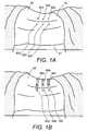
- FIG. 1Ais a top view of the back of a patient positioned prone on the operating table in preparation for spinal surgery;
- FIG. 1Bis a top view of the patient's back with portals inserted in the areas of the pathology
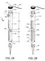
- FIG. 2Ais a perspective view of a portal with an adjustable length, according to this invention.
- FIG. 2Bis another perspective view of the portal of FIG. 2A ;
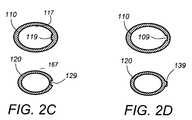
- FIG. 2Cis a cross-sectional view of the outer and inner cannulae of FIG. 2A ;
- FIG. 2Dis a cross-sectional view of another embodiment of the outer and inner cannulae of FIG. 2A ;
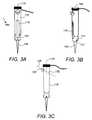
- FIG. 3A-3Care perspective views of an assembled portal, according to this invention.
- FIG. 4is a layered top view of the patient's back with incisions made on the skin extending through the lumbodorsal fascia to the deep tissues;
- FIG. 5is a layered top view of the patient's back with incisions made on the skin and guide wires placed percutaneously through the skin and into the underlying vertebrae;
- FIG. 6is top view of the patient's back with portals placed in the openings formed from the skin surface and extending deep into the pathology areas;
- FIG. 7is a top view of the patient's back as in FIG. 6 with a pair of curved scissors placed through a portal of this invention
- FIG. 8is a top view of the patient's back as in FIG. 6 with a carrier device placed through a portal of this invention
- FIG. 9is a top view of the patient's back as in FIG. 6 with a carrier device placed through a portal of this invention, the carrier device carrying a connecting rod for placement between adjacent vertebrae;
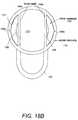
- FIG. 9Ais a cross-section of the front portion of a carrier device in the open position
- FIG. 9Bis a cross-section of the front portion of the carrier device of FIG. 9A in the closed position
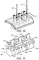
- FIG. 10is a top view of the patient's back with two rod carrier devices placed in two different portals for inserting an entire rod in the area between the two portals, under the skin and lumbodorsal fascia and attaching it to the connection points;
- FIG. 11is a top view of a connecting rod that was placed in the slots of three sequential pedicle screws using the portals of this invention.
- FIG. 12is a front view of a connecting articulating device that was connected to three sequential pedicle screws using the portals of this invention
- FIG. 13is a perspective view of a connecting articulating device that was placed under the skin and lumbodorsal fascia and was connected to three sequential pedicle screws using the portals of this invention;
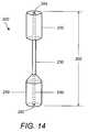
- FIG. 14is a front view of a cannulated tissue dilator that when rotated creates a cylindrical space along its path;
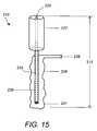
- FIG. 15is a front view of a collapsible tissue dilator that can be inflated to create a space along its path;
- FIG. 16is a block diagram of a spinal operating procedure utilizing the portals of this invention.
- FIG. 17Ais a perspective view of another embodiment of a portal with an adjustable length, according to this invention.
- FIG. 17Bis a top view of the embodiment of FIG. 17A ;
- FIG. 18Ais a perspective view of another embodiment of a portal with an adjustable length, according to this invention.
- FIG. 18Bis a top view of the embodiment of FIG. 18A ;
- FIG. 19Ais a perspective view of another embodiment of a portal with an adjustable length, according to this invention.
- FIG. 19Bis a top view of the embodiment of FIG. 19A ;
- FIG. 20Ais a perspective view of another embodiment of a portal with an adjustable length, according to this invention.
- FIG. 20Bis a top view of the embodiment of FIG. 20A ;
- FIG. 21depicts a perspective view, a top view, a front view and a side view of a carrier device.
- a patient 90is positioned prone, lying flat on an operating table 91 in preparation for a minimally invasive surgery (MIS).
- Locations 92 a - 92 fare marked on the patient's lower back corresponding to pedicle locations of adjacent vertebrae.
- portals 94 a - 94 fare inserted through skin incisions performed in the marked locations 92 a - 92 f , respectively, shown in FIG. 1B .
- portal 94 aincludes an outer elongated cannula 110 and an inner elongated cannula 120 .
- Inner cannula 120slides within outer cannula 110 and is secured at different locations of the inner wall of the outer cannula 110 , thereby forming a first working channel 115 with adjustable length. This is especially desirable for reaching locations within the patient's body corresponding to the outer locations 92 a - 92 f , that are at different distances from the patient's skin 70 .
- Outer cannula 110has millimeter markers 192 etched on the outside surface to allow determination of the depth of the pathology (shown in FIG. 17A ).
- Portal 94 ahas an outer diameter sized for percutaneous placement within the patient's body.
- the outer diameter of portal 94 aas defined by the outer diameter 111 a of the outer cannula 110 , is 20 mm.
- Outer cannula 110includes two elongated pieces 110 a , 110 b , extending from the distal end 113 of the main hollow cylindrical body 114 and forming an opening 118 a between them.
- the proximal end 112 of the hollow cylindrical body 114has a circular opening with an inner diameter 111 b , and the previously mentioned outer diameter 111 a .
- the outer cannula 110has a length 116 of 40 mm, an inner diameter 111 b of 18 mm and an outer diameter 111 a of 20 mm.
- the outer cannulafurther includes a side portal 130 and an opening 132 located opposite to the side portal thereby defining a second working channel 135 (shown in FIG. 3C ).
- the second working channel 135communicates with the first working channel 115 .
- more than one side portalsare included and may be located at any location along the outer or inner cannula or may be detachable.
- elongated pieces 10 a and 110 bmay extend directly from the base of side portal 130 .
- side portal 130may communicate directly with the proximal opening of cylindrical body 114 .
- side portal 130is fixed at an angle relative to the outer cannula 110 .
- side portal 130may be hinged so that it can be placed at variable angles along the outer cannula 110 .
- Side portal 130functions as an automatic stop against the patient's skin 70 , while the inner cannula 120 slides within the outer cannula 110 and elongates in order to reach the location of the pathology within the patient's body. Accordingly, the exposed length of the various outer cannulae above the skin may remain the same while the entire length of the portals variably elongates. It is important for the surgeon to have a consistent height of the cannula above the skin surface which may otherwise vary with different patient body habitus.
- the inner cannula 120includes a main hollow cylindrical body 122 and two elongated pieces 120 a , 120 b extending from the proximal end 123 of the main body 122 .
- An opening 118 bis formed between the two elongated pieces 120 a , 120 b .
- inner cannula 120further includes a slot 121 at the distal end of the main body 122 that functions as a docking element for attaching a device or a connecting element to the distal end of the inner cannula 120 .
- the element shown 140is a pedicle screw with an extension 141 that fits within the slot 121 .
- inner cannula 120has a length 124 of 40 mm, an inner diameter 127 of 17 mm, and an outer diameter 128 of 17.75 mm. In other embodiments the outer diameter 128 may be in the range of 17.5 to 18 mm.
- inner cannula 120 and outer cannula 110have uniform inner and outer diameters. In other embodiments, the diameters may be non-uniform and the cannulae may be tapered at one or both ends. In other embodiments the opening 118 b in cannula 120 may extend through the distal ends of both sides of cannula 120 without connecting the elongated pieces 120 a and 120 b or only on one side connecting either 120 a or 120 b.
- the outer cannula 110further includes an appendage 119 formed within the inner wall 117 of the outer cannula 110 and extending the entire length 116 of the cannula 110 .
- Appendage 119slides within a groove 129 formed on the outer wall 167 of cannula 120 .
- Groove 129extends the length 124 of the inner cannula 120 ending prior to reaching the top of cannula 120 so that there is a stop to complete separation of the cannulae as they elongate against each other and allows removal of the cannulae as one piece.
- Cannula 120may have a lip at the top edge which overhangs to fit within the space within the wall of cannula 110 and stops against a ledge at the bottom of cannula 110 .
- the outer cannula 110may have a groove 109 in the inner wall 117 and the inner cannula 120 may have an appendage 139 in the outer wall 167 and the appendage 139 of the inner cannula 120 may slide within the groove 109 of the outer cannula 110 in a tongue and groove type fashion, as shown in FIG. 2D .
- Groove 109ends prior to reaching the most distal surface of the outer cannula 110 so that there is a stop to complete separation of the cannulae as they elongate against each other and allows removal of the cannulae as one piece.
- the inner groves 109 and 129may have serrations that allow a ratchet-type incremental elongation and shortening of the combined lengths of the cannulae 110 and 120 .
- the ratchet-type mechanismalso functions as a height securing mechanism which is an adjunct to the automatic height adjustment that occurs between the side portal 130 contacting the skin and the pedicle screw 140 contacting the vertebra as the cannulae elongate against each other.
- the surfaces of the inner wall 117 and outer wall 167are smooth.
- portal 94 adynamically adjusts its height automatically as the pedicle screw 140 advances within the pedicle since the distal end 122 of the inner cannula 120 is fixed to the screw 140 and each cannula 110 , 120 is permitted to slide relative to each other.
- the inner cannula 120slides within a space formed between the inner and outer diameter of cannula 110 .
- portal 400includes an outer hollow cannula 110 and an inner hollow tube 190 placed with the hollow outer cannula 110 .
- the diameter of the inner tube 190is smaller than the inner diameter of the outer cannula 110 and a space 198 is formed between them.
- Inner cannula 120is sized to fit within the space 198 and to slide against the inner wall 117 of the outer cannula 110 and the outer wall 199 of the inner tube 198 .
- the inner wall 117 of outer cannula 110includes a groove 109 a extending the entire length 116 of the cannula 110 and the outer wall of the inner cannula 120 includes an appendage 139 a .
- Appendage 139 aslides within the groove 109 a in a tongue and groove type configuration.
- Appendage 139 aextends the length 124 of the inner cannula 120 ending prior to reaching the top of cannula 120 so that there is a stop to complete separation of the cannulae as they elongate against each other and allows removal of the cannulae as one piece.
- a second appendage 139 b placed diametrically opposite the first appendage 139 a on the outer wall of the inner cannula 120slides within a second groove 109 b placed diametrically opposite the first groove 109 b on the inner wall of the outer cannula 110 .
- portal 420includes an outer cannula 110 and two inner cannulae 120 a and 120 b .
- Inner cannula 120 aslides against the inner cylindrical wall 117 of the outer cannula 110 , against four planar walls 194 a , 194 b , 194 c , of the outer cannula 110 and against the outer cylindrical wall of the inner cannula 120 b .
- Inner cannula 120 bslides against the inner cylindrical wall of inner cannula 120 a.
- the outer cannula 110slides within the inner cannula 120 (not shown).
- the portal 440extends in a telescopic fashion as one piece. In this embodiment, the length is adjusted by unscrewing the outer cannula 110 or screwing the inner cannula 120 in each case relative to each other.
- inner cannula 120is rotated relative to the outer cannula 110 so that openings 118 a and 118 b are aligned, forming an elongated pass-through slot 118 when the portal 94 a is assembled.
- Pedicle screw 140includes an appendage 141 and is attached to the inner cannula 120 by engaging the appendage 141 to the outer cannula slot 121 , as shown in FIG. 3B . In this embodiment access to the pedicle screw is achieved through the first working channel 115 . In another embodiment the pedicle screw is engaged as an interference fit within the distal end of cannula 120 . In either case a screw drive or pushing device fits into the head of the pedicle screw and stabilizes the screw, if the head is multiaxial, while it is being inserted deep into the body cavity.
- a detachable optical and/or illumination device 194is interference fitted to the proximal end 112 of the outer cannula 110 and is capable of rotating around an axis passing through the first channel 115 .
- the optical and/or illumination devicemay be a light source and/or an optical fiber that has one end connecting to a light source and a second end placed in the vicinity of the pathology area, thereby providing direct illumination and visualization of the pathology area.
- the illumination devicemay be fitted through the side portal 130 or through an inverted L-shaped appendage protruding from the inner wall of the outer cannula 110 into the first working channel and consisting of a hollow inner core that communicates with the inner and outer diameters of the outer cannula 110 and is sized to receive the optical device and/or the light source.
- the optical devicemay be similarly connected to inner cannula 120 .
- Customized instrumentsare also provided for insertion within the first working channel 115 or the second working channel 135 .
- a customized curved pair of scissors 150is inserted through the first working channel 115 of portal 94 c .
- scissors 150are inserted through the side portal 130 .
- Scissors 150is used to incise the lumbodorsal fascia 75 in the area 72 b between two adjacent portals 94 c and 94 b for opening a path 74 b between them.
- This path 74 bis then used for delivering and placing bone graft, connecting elements, such as rods, plates, wires, or articulating versions thereof, for connecting the adjacent vertebrae 82 c and 82 b of the spine 80 .
- the connecting elementsare then secured to the corresponding vertebrae 82 c , 82 b via screws placed through the first working channels 115 of the corresponding portals 94 c , 94 b .
- paths 74 a , 74 c , 74 dmay be opened in the areas 72 a , 72 c , 72 d between the adjacent portals 94 b and 94 a , 94 d and 94 e , and 94 e and 94 d , respectively.
- Other types of incision instrumentsmay also be used, including curved scalpels, among others.
- the curved scissors 150is inserted through the working channel 135 .
- a customized curved carrier instrument 160is inserted through the opening of the second working channel 135 of portal 94 c and passes through the opened path 74 b between the adjacent portals 94 c , 94 b .
- Instrument 160enters the first working channel of portal 94 b through the side slot 118 .
- Instrument 160is used for delivering the above mentioned bone graft, connecting elements 170 , screws or biological materials in the areas between the adjacent portals.
- the front portion 162 of the carrier instrument 160includes an elongated semi-cylindrical groove for carrying the connecting elements 170 .
- the front portion 162may be a cylindrical tube as one piece or two separate pieces which can rotate relative to each other to form a cylinder or a half cylinder, shown in FIG. 9A and FIG. 9B .
- the tip of the carrier instrument 160may be shaped as the tip of a bullet or a canoe to shield the devices being carried from the surrounding soft tissues as the carrier device is forced through the tissues between the adjacent portals 94 c , 94 b .
- the carrier instrument 160may be flexible, malleable, or rigid and may be expandable at body temperature.
- a customized tissue dilator instrument 200is provided for developing a path in the soft tissues from the skin surface 70 of the patient's body 90 to a desired depth within the patient's body.
- Instrument 200includes a handle 220 that connects to a shaft 230 and the shaft 230 connects to a paddle 250 .
- An elongated cannula 240extends the entire length 202 of the instrument 200 and connects an opening 204 at the proximal end of the handle to an opening 260 at the distal end of the paddle 250 .
- Instrument 210is used for developing a path in the soft tissues from the skin surface 70 of the patient's body 90 to a desired depth within the patient's body and for removing the soft tissues along the opened path.
- Instrument 210includes a handle 227 that connects to a shaft 232 having a cannula 233 .
- Cannula 233extends the entire length of the instrument 212 and has a proximal opening 234 and a distal opening 231 .
- Shaft 232is surrounded by an inflatable balloon-type component 229 which when inflated through a connected tube 228 and moved up and down from the surface 70 to the deeper layers, clears a cylindrical space in the soft-tissues along the path of the instrument equal in diameter to the largest diameter of the inflated component 229 .
- FIG. 16The steps of a spinal surgical procedure 300 in accordance with one aspect of the present invention are depicted schematically in the block diagram of FIG. 16 and figuratively in FIG. 1 to FIG. 15 .
- the present embodiment of the inventionpermits a substantially mid-line or medial posterior or postero-lateral approach to the spine but other approaches to other parts of the body are understood to be feasible with this invention.
- FIG. 16 , FIG. 1 and FIG. 4in a first step of the technique, small incisions are made in the patient's skin 70 along the spine 80 creating skin openings 92 a - 92 f ( 302 ).
- guide wires 96 a - 96 fare advanced through the skin openings 92 a - 92 f , respectively, through the underlying tissue and into the bony anatomy of a vertebral element such as a pedicle ( 304 ).
- the wiresare inserted under fluoroscopic vision or as an open procedure under direct vision.
- a tissue dilator as depicted in FIG. 14 and FIG. 15is advanced over the guide wires ( 306 ).
- the dilatoris either inflated (as in FIG. 15 ) or rotated (as in FIG. 14 ) and withdrawn slowly to develop a channel from the skin to the fixation point of the guide wire.
- a fixation devicesuch as a pedicle screw 140 is attached to each of the working portals 94 a - 94 f and secured via the locking mechanism 141 , as depicted in FIG. 2A and FIG. 3A ( 308 ).
- a cannulated screwdriver or an elongated instrumentis connected to the fixation device 140 and combined with the portal assembly is advanced through the incision ( 312 ).
- the portal assemblies 94 a - 94 f including the pedicle screw 140 and screwdriverare inserted over the guide wires 96 a - 96 f , respectively, and into the bone as depicted in FIG. 6 ( 310 ).
- a second tissue dilatorhaving a cylindrical shape similar to the portal assembly but with a larger diameter and with an opening slot running unilaterally along its entire length may be inserted through the skin opening and left in place so that the portal assembly can be inserted inside of this second dilator thereby preventing tissue being caught within the portal assembly.
- the second dilatorcan then be removed when the portal assembly is inserted by sliding the second dilator around the portal assembly via the opened channel.
- portals with fixed lengthusually protrude high above the level of the patient's skin and require external support for stability.
- This inventiondoes not require an external support for the portal because the length of the protruding portal is always constant because the portion beneath the skin is adjustable. However, an external support may be attached to either the main portal or the side working portal for added stability.
- a pair of curved facial scissors 150 or curved scalpelis then inserted through the working channel 115 of portal 94 c or through channel 135 of side portal 130 and advanced beneath the patient's skin 70 while cutting through the lumbodorsal fascia 75 until the scissor tips enter the next adjacent portal 94 b through the slot 118 , as in FIG. 9 ( 316 ).
- the lumbodorsal fasciais completely discontinuous in the area 72 b between the two portals 94 c and 94 b .
- a carrier device 160is then inserted through channel 135 of side portal 130 across the soft tissues either above or below the level of the lumbodorsal fascia 75 until the tip of the carrier enters the next adjacent portal 94 b ( 318 ).
- the carrier device 160has a semi-cylindrical front portion 162 that is used to support various objects that need to be inserted into the pathology areas.
- a connecting device 170such as a cylindrical rod, plate, articulating device, or biologic substances is placed in the semi-cylindrical front portion 162 either before insertion or after insertion and is brought in the tissue area between portal 94 c and 94 b .
- the front portion 162has a full cylindrical shape or includes two semi-cylindrical segments 162 a and 162 b that can open or close to form either an open semi cylinder or a closed cylinder, as shown in FIG. 9A and FIG. 9B , respectively.
- This stepcan be repeated between multiple adjacent portals or across sets of portals for segmental fixation as shown in FIG. 11 , FIG. 12 and FIG. 13 .
- the carrier device 160is retracted from the portals and the connecting device 170 is then inserted to the base of the portals or until it engages the fixation elements 140 , such as a pedicle screw, as shown in FIGS. 11-13 ( 322 ).
- Pushers 164are available to apply force to the connecting device 170 as it advances through the soft tissues.
- This techniqueallows the connecting device 170 to approach the fixation points in a direct fashion rather than indirectly at an angle or indirectly via a predetermined arc.
- This techniquealso only uses direct vision at the fixation points while not seeing the portion of the connecting device between the fixation points. This diminishes the size of the soft tissue dissection and trauma as well as the incision size.
- locking screwsare then used to secure the connecting device to the fixation points ( 322 ).
- the main tubeis pushed downwards and turned counterclockwise or clockwise to disengage the appendage 141 from the slot 121 ( 324 ). It is understood that the slot may be vertical only or horizontal only or a combination of the two or other configurations not specified in this invention.
- the tubeis then removed from the incision and the incision closed in a standard fashion ( 324 ).
- One of the unique features of this inventionis the ability to engage and disengage the portals to and from the fixation devices 140 , respectively, at any point during the operating procedure.
- the dilator device of FIG. 15is placed in the depth of the incision and inflated to reopen the path to the fixation device 140 .
- the portal 94 ais replaced over the fixation device 140 and engages the appendage 141 on the fixation device 140 , which in this case is a locking screw.
- the locking screwis then removed. This process is then repeated for as many fixation points as necessary.
- the connecting device 170is either advanced laterally to disengage one or more fixation points 140 a - 140 c or it is grasped at each fixation point under direct vision and advanced upwards.
- the carrier 160is then advanced beneath one end of the connecting device 170 and then the connecting device is grasped at that end and pulled diagonally along the carrier 160 out of the incision through the end of the working portal 94 b . With the portals engaged the procedure can be repeated from any point according to the sequence described above.
- an optic and or illumination device 194can be connected at varying locations on cannula 110 , 120 or working channel 135 .
- the optic or illumination deviceis most preferably a fiber optic, although a rod lens scope or other viewing scopes may be utilized.
- the portalis freely situated within the patient's skin and soft tissues, it can be manipulated to be centered over the target region. Repositioning of the portal can be performed manually under fluoroscopic guidance or be fitted with a position sensing devices, such as LEDs, in order to be guided stereotactically.
- a variety of procedures using a variety of instrumentscan be performed through the main working channel 115 or the side channel 135 . It is understood that these various tools and instruments are designed to fit through the working channels.
- the working channel 115 through the cannulae 110 and 120have a maximum inner diameter of 13 mm and the working channel 135 a maximum diameter of 10 mm.
- the present inventionis not limited to the diameters mentioned for the working channels, since the dimensions of the components will vary depending upon the anatomy of the surgical site and the type of procedure being performed and as such the channels will vary.
- irrigationmay be provided separately through the working channel 135 to keep the visualization space clear. Separate or combined irrigation and aspiration elements can also be inserted through the working channel 135 or the main channel 115 as required by the procedure. In another embodiment the irrigation and aspiration elements may be combined with the optic and or illumination assembly or some combination thereof.
- the cannulaemay have other cross-sections such as rectangular or square.
- the cannulaemay be flexible or semi rigid.
- the devicesmay be made of metal such as stainless steel, titanium, plastic, rubber, graphite, glass, expandable materials under body temperature, or other radiolucent materials.
Landscapes
- Health & Medical Sciences (AREA)
- Orthopedic Medicine & Surgery (AREA)
- Neurology (AREA)
- Surgery (AREA)
- Life Sciences & Earth Sciences (AREA)
- Medical Informatics (AREA)
- Biomedical Technology (AREA)
- Heart & Thoracic Surgery (AREA)
- Engineering & Computer Science (AREA)
- Molecular Biology (AREA)
- Animal Behavior & Ethology (AREA)
- General Health & Medical Sciences (AREA)
- Public Health (AREA)
- Veterinary Medicine (AREA)
- Nuclear Medicine, Radiotherapy & Molecular Imaging (AREA)
- Pathology (AREA)
- Surgical Instruments (AREA)
- Prostheses (AREA)
Abstract
Description
Claims (23)
Priority Applications (14)
| Application Number | Priority Date | Filing Date | Title |
|---|---|---|---|
| US10/868,075US7955355B2 (en) | 2003-09-24 | 2004-06-15 | Methods and devices for improving percutaneous access in minimally invasive surgeries |
| PCT/US2004/036640WO2005072081A2 (en) | 2003-11-08 | 2004-11-04 | Methods and devices for improving percutaneous access in minimally invasive surgeries |
| US11/202,487US8002798B2 (en) | 2003-09-24 | 2005-08-12 | System and method for spinal implant placement |
| US13/100,640US8685063B2 (en) | 2003-09-24 | 2011-05-04 | Methods and devices for improving percutaneous access in minimally invasive surgeries |
| US13/972,493USRE45338E1 (en) | 2003-09-24 | 2013-08-21 | System and method for spinal implant placement |
| US13/973,462USRE45676E1 (en) | 2003-09-24 | 2013-08-22 | System and method for spinal implant placement |
| US14/186,619US9700357B2 (en) | 2003-09-24 | 2014-02-21 | Methods and devices for improving percutaneous access in minimally invasive surgeries |
| US14/824,951USRE46432E1 (en) | 2003-09-24 | 2015-08-12 | System and method for spinal implant placement |
| US15/616,248US10143502B2 (en) | 2003-11-08 | 2017-06-07 | Methods and devices for improving percutaneous access in minimally invasive surgeries |
| US15/620,402USRE47348E1 (en) | 2003-11-08 | 2017-06-12 | System and method for spinal implant placement |
| US16/168,000US10993747B2 (en) | 2003-11-08 | 2018-10-23 | Methods and devices for improving percutaneous access in minimally invasive surgeries |
| US16/384,315USRE48376E1 (en) | 2003-11-08 | 2019-04-15 | System and method for spinal implant placement |
| US17/138,167USRE49432E1 (en) | 2003-11-08 | 2020-12-30 | System and method for spinal implant placement |
| US17/231,329US20210298797A1 (en) | 2003-11-08 | 2021-04-15 | Methods And Devices For Improving Percutaneous Access In Minimally Invasive Surgeries |
Applications Claiming Priority (3)
| Application Number | Priority Date | Filing Date | Title |
|---|---|---|---|
| US10/669,927US7282064B2 (en) | 2003-02-11 | 2003-09-24 | Apparatus and method for connecting spinal vertebrae |
| US51858003P | 2003-11-08 | 2003-11-08 | |
| US10/868,075US7955355B2 (en) | 2003-09-24 | 2004-06-15 | Methods and devices for improving percutaneous access in minimally invasive surgeries |
Related Parent Applications (1)
| Application Number | Title | Priority Date | Filing Date |
|---|---|---|---|
| US10/669,927Continuation-In-PartUS7282064B2 (en) | 2003-02-11 | 2003-09-24 | Apparatus and method for connecting spinal vertebrae |
Related Child Applications (4)
| Application Number | Title | Priority Date | Filing Date |
|---|---|---|---|
| US11/202,487Continuation-In-PartUS8002798B2 (en) | 2003-09-24 | 2005-08-12 | System and method for spinal implant placement |
| US11/202,487ContinuationUS8002798B2 (en) | 2003-09-24 | 2005-08-12 | System and method for spinal implant placement |
| US13/100,640DivisionUS8685063B2 (en) | 2003-09-24 | 2011-05-04 | Methods and devices for improving percutaneous access in minimally invasive surgeries |
| US13/972,493Continuation-In-PartUSRE45338E1 (en) | 2003-09-24 | 2013-08-21 | System and method for spinal implant placement |
Publications (2)
| Publication Number | Publication Date |
|---|---|
| US20050065517A1 US20050065517A1 (en) | 2005-03-24 |
| US7955355B2true US7955355B2 (en) | 2011-06-07 |
Family
ID=34830393
Family Applications (6)
| Application Number | Title | Priority Date | Filing Date |
|---|---|---|---|
| US10/868,075Active2026-05-08US7955355B2 (en) | 2003-09-24 | 2004-06-15 | Methods and devices for improving percutaneous access in minimally invasive surgeries |
| US13/100,640Expired - LifetimeUS8685063B2 (en) | 2003-09-24 | 2011-05-04 | Methods and devices for improving percutaneous access in minimally invasive surgeries |
| US14/186,619Expired - Fee RelatedUS9700357B2 (en) | 2003-09-24 | 2014-02-21 | Methods and devices for improving percutaneous access in minimally invasive surgeries |
| US15/616,248Expired - LifetimeUS10143502B2 (en) | 2003-11-08 | 2017-06-07 | Methods and devices for improving percutaneous access in minimally invasive surgeries |
| US16/168,000Expired - Fee RelatedUS10993747B2 (en) | 2003-11-08 | 2018-10-23 | Methods and devices for improving percutaneous access in minimally invasive surgeries |
| US17/231,329AbandonedUS20210298797A1 (en) | 2003-11-08 | 2021-04-15 | Methods And Devices For Improving Percutaneous Access In Minimally Invasive Surgeries |
Family Applications After (5)
| Application Number | Title | Priority Date | Filing Date |
|---|---|---|---|
| US13/100,640Expired - LifetimeUS8685063B2 (en) | 2003-09-24 | 2011-05-04 | Methods and devices for improving percutaneous access in minimally invasive surgeries |
| US14/186,619Expired - Fee RelatedUS9700357B2 (en) | 2003-09-24 | 2014-02-21 | Methods and devices for improving percutaneous access in minimally invasive surgeries |
| US15/616,248Expired - LifetimeUS10143502B2 (en) | 2003-11-08 | 2017-06-07 | Methods and devices for improving percutaneous access in minimally invasive surgeries |
| US16/168,000Expired - Fee RelatedUS10993747B2 (en) | 2003-11-08 | 2018-10-23 | Methods and devices for improving percutaneous access in minimally invasive surgeries |
| US17/231,329AbandonedUS20210298797A1 (en) | 2003-11-08 | 2021-04-15 | Methods And Devices For Improving Percutaneous Access In Minimally Invasive Surgeries |
Country Status (2)
| Country | Link |
|---|---|
| US (6) | US7955355B2 (en) |
| WO (1) | WO2005072081A2 (en) |
Cited By (79)
| Publication number | Priority date | Publication date | Assignee | Title |
|---|---|---|---|---|
| US20080082103A1 (en)* | 2006-06-16 | 2008-04-03 | Alphatec Spine, Inc. | Systems and methods for manipulating and/or installing a pedicle screw |
| US20080183045A1 (en)* | 2007-01-30 | 2008-07-31 | Mi4Spine, Llc | Retractor Device for Cervical Spinal Fusion |
| US20090099605A1 (en)* | 2006-02-06 | 2009-04-16 | Stryker Spine | Rod contouring apparatus for percutaneous pedicle screw extension |
| US20090138053A1 (en)* | 2007-09-25 | 2009-05-28 | Zyga Technology, Inc. | Method and apparatus for facet joint stabilization |
| US20110015678A1 (en)* | 2004-11-23 | 2011-01-20 | Jackson Roger P | Spinal fixation tool set and method |
| US20120016422A1 (en)* | 2008-10-01 | 2012-01-19 | Sherwin Hua | Systems and methods for pedicle screw stabilization of spinal vertebrae |
| US8394125B2 (en) | 2009-07-24 | 2013-03-12 | Zyga Technology, Inc. | Systems and methods for facet joint treatment |
| US8663293B2 (en) | 2010-06-15 | 2014-03-04 | Zyga Technology, Inc. | Systems and methods for facet joint treatment |
| US8685063B2 (en) | 2003-09-24 | 2014-04-01 | Stryker Spine | Methods and devices for improving percutaneous access in minimally invasive surgeries |
| US8696707B2 (en) | 2005-03-08 | 2014-04-15 | Zyga Technology, Inc. | Facet joint stabilization |
| EP2777573A1 (en) | 2013-03-14 | 2014-09-17 | Stryker Spine | Access device for percuataneous spinal fusion |
| USRE45338E1 (en) | 2003-09-24 | 2015-01-13 | Stryker Spine | System and method for spinal implant placement |
| US20150080896A1 (en) | 2013-07-19 | 2015-03-19 | Ouroboros Medical, Inc. | Anti-clogging device for a vacuum-assisted, tissue removal system |
| US20150173809A1 (en)* | 2013-12-20 | 2015-06-25 | Globus Medical, Inc. | Orthopedic Fixation Devices and Instruments for Installation Thereof |
| EP2898836A1 (en) | 2013-12-13 | 2015-07-29 | Stryker European Holdings I, LLC | Tissue retraction and vertebral displacement devices, systems. |
| US9119659B2 (en) | 2011-12-03 | 2015-09-01 | Ouroboros Medical, Inc. | Safe cutting heads and systems for fast removal of a target tissue |
| US9125703B2 (en) | 2012-01-16 | 2015-09-08 | K2M, Inc. | Rod reducer, compressor, distractor system |
| US9192415B1 (en) | 2008-02-06 | 2015-11-24 | Nuvasive, Inc. | Systems and methods for holding and implanting bone anchors |
| US9198698B1 (en) | 2011-02-10 | 2015-12-01 | Nuvasive, Inc. | Minimally invasive spinal fixation system and related methods |
| US9233006B2 (en) | 2010-06-15 | 2016-01-12 | Zyga Technology, Inc. | Systems and methods for facet joint treatment |
| US20160095631A1 (en)* | 2013-03-14 | 2016-04-07 | DePuy Synthes Products, Inc. | Methods and devices for polyaxial screw alignment |
| US9314274B2 (en) | 2011-05-27 | 2016-04-19 | DePuy Synthes Products, Inc. | Minimally invasive spinal fixation system including vertebral alignment features |
| US9402663B2 (en) | 2010-04-23 | 2016-08-02 | DePuy Synthes Products, Inc. | Minimally invasive instrument set, devices and related methods |
| US9408716B1 (en) | 2013-12-06 | 2016-08-09 | Stryker European Holdings I, Llc | Percutaneous posterior spinal fusion implant construction and method |
| US9452000B2 (en) | 2013-10-07 | 2016-09-27 | K2M, Inc. | Rod reducer |
| US9498262B2 (en) | 2006-04-11 | 2016-11-22 | DePuy Synthes Products, Inc. | Minimally invasive fixation system |
| US9596428B2 (en) | 2010-03-26 | 2017-03-14 | Echostar Technologies L.L.C. | Multiple input television receiver |
| WO2017066518A1 (en)* | 2010-06-29 | 2017-04-20 | Mighty Oak Medical, Inc. | Patient-matched apparatus and methods for performing surgical procedures |
| US9693882B2 (en) | 2014-06-03 | 2017-07-04 | DePuy Synthes Products, Inc. | Optical trial device |
| US9700354B2 (en) | 2004-11-23 | 2017-07-11 | Roger P. Jackson | Polyaxial bone screw with multi-part shank retainer and pressure insert |
| US9744050B1 (en) | 2013-12-06 | 2017-08-29 | Stryker European Holdings I, Llc | Compression and distraction system for percutaneous posterior spinal fusion |
| US20170303976A1 (en)* | 2006-08-22 | 2017-10-26 | DePuy Synthes Products, Inc. | Reduction sleeve |
| US9808281B2 (en) | 2009-05-20 | 2017-11-07 | DePuy Synthes Products, Inc. | Patient-mounted retraction |
| US9827020B2 (en) | 2013-03-14 | 2017-11-28 | Stryker European Holdings I, Llc | Percutaneous spinal cross link system and method |
| US9833328B2 (en) | 2010-06-15 | 2017-12-05 | Zyga Technology | System and methods for facet joint treatment |
| US9895182B2 (en) | 2005-05-18 | 2018-02-20 | Stryker European Holdings I. Llc | System and method for orthopedic implant configuration |
| US9921276B2 (en) | 2006-08-11 | 2018-03-20 | DePuy Synthes Products, Inc. | Simulated bone or tissue manipulation |
| US9943344B2 (en) | 2015-01-15 | 2018-04-17 | K2M, Inc. | Rod reducer |
| US9974577B1 (en) | 2015-05-21 | 2018-05-22 | Nuvasive, Inc. | Methods and instruments for performing leveraged reduction during single position spine surgery |
| US10004558B2 (en) | 2009-01-12 | 2018-06-26 | Ethicon Endo-Surgery, Inc. | Electrical ablation devices |
| US10034690B2 (en) | 2014-12-09 | 2018-07-31 | John A. Heflin | Spine alignment system |
| CN108366791A (en)* | 2015-10-14 | 2018-08-03 | 麦迪欧克医疗公司 | The matched device and method of patient for carrying out surgical operation |
| US10039578B2 (en) | 2003-12-16 | 2018-08-07 | DePuy Synthes Products, Inc. | Methods and devices for minimally invasive spinal fixation element placement |
| US10105141B2 (en) | 2008-07-14 | 2018-10-23 | Ethicon Endo-Surgery, Inc. | Tissue apposition clip application methods |
| US10159579B1 (en) | 2013-12-06 | 2018-12-25 | Stryker European Holdings I, Llc | Tubular instruments for percutaneous posterior spinal fusion systems and methods |
| US10206709B2 (en) | 2012-05-14 | 2019-02-19 | Ethicon Llc | Apparatus for introducing an object into a patient |
| US10258406B2 (en) | 2011-02-28 | 2019-04-16 | Ethicon Llc | Electrical ablation devices and methods |
| US10278761B2 (en) | 2011-02-28 | 2019-05-07 | Ethicon Llc | Electrical ablation devices and methods |
| US10314603B2 (en) | 2008-11-25 | 2019-06-11 | Ethicon Llc | Rotational coupling device for surgical instrument with flexible actuators |
| US10342598B2 (en) | 2012-08-15 | 2019-07-09 | Ethicon Llc | Electrosurgical system for delivering a biphasic waveform |
| US10368881B2 (en) | 2016-06-03 | 2019-08-06 | Quandary Medical, Llc | Method and apparatus for minimally invasive posterolateral spinal fusion |
| USD857893S1 (en) | 2017-10-26 | 2019-08-27 | Mighty Oak Medical, Inc. | Cortical surgical guide |
| USD858765S1 (en) | 2017-10-26 | 2019-09-03 | Mighty Oak Medical, Inc. | Cortical surgical guide |
| US10398481B2 (en) | 2016-10-03 | 2019-09-03 | Nuvasive, Inc. | Spinal fixation system |
| US10405896B2 (en) | 2015-04-30 | 2019-09-10 | K2M, Inc. | Rod reducer |
| US10478248B2 (en) | 2007-02-15 | 2019-11-19 | Ethicon Llc | Electroporation ablation apparatus, system, and method |
| US10485590B2 (en) | 2017-01-18 | 2019-11-26 | K2M, Inc. | Rod reducing device |
| US10492880B2 (en) | 2012-07-30 | 2019-12-03 | Ethicon Llc | Needle probe guide |
| US10524843B2 (en) | 2016-05-06 | 2020-01-07 | K2M, Inc. | Rotation shaft for a rod reducer |
| US10653454B2 (en) | 2007-07-13 | 2020-05-19 | Mighty Oak Medical, Inc. | Spinal fixation systems |
| US10702309B2 (en) | 2004-11-23 | 2020-07-07 | Roger P. Jackson | Pivotal bone anchor assembly with multi-part shank retainer and rod-engaging insert |
| US10743890B2 (en) | 2016-08-11 | 2020-08-18 | Mighty Oak Medical, Inc. | Drill apparatus and surgical fixation devices and methods for using the same |
| USD895111S1 (en) | 2018-06-04 | 2020-09-01 | Mighty Oak Medical, Inc. | Sacro-iliac guide |
| US10779866B2 (en) | 2016-12-29 | 2020-09-22 | K2M, Inc. | Rod reducer assembly |
| US10779882B2 (en) | 2009-10-28 | 2020-09-22 | Ethicon Endo-Surgery, Inc. | Electrical ablation devices |
| US10973551B2 (en) | 2008-10-01 | 2021-04-13 | Sherwin Hua | Systems and methods for pedicle screw stabilization of spinal vertebrae |
| US11039889B2 (en) | 2010-06-29 | 2021-06-22 | Mighty Oak Medical, Inc. | Patient-matched apparatus and methods for performing surgical procedures |
| US11051861B2 (en) | 2018-06-13 | 2021-07-06 | Nuvasive, Inc. | Rod reduction assemblies and related methods |
| US11160580B2 (en) | 2019-04-24 | 2021-11-02 | Spine23 Inc. | Systems and methods for pedicle screw stabilization of spinal vertebrae |
| USD948717S1 (en) | 2018-06-04 | 2022-04-12 | Mighty Oak Medical, Inc. | Sacro-iliac guide |
| US11376073B2 (en) | 2010-06-29 | 2022-07-05 | Mighty Oak Medical Inc. | Patient-matched apparatus and methods for performing surgical procedures |
| US11484191B2 (en) | 2013-02-27 | 2022-11-01 | Cilag Gmbh International | System for performing a minimally invasive surgical procedure |
| US11633254B2 (en) | 2018-06-04 | 2023-04-25 | Mighty Oak Medical, Inc. | Patient-matched apparatus for use in augmented reality assisted surgical procedures and methods for using the same |
| US11806197B2 (en) | 2010-06-29 | 2023-11-07 | Mighty Oak Medical, Inc. | Patient-matched apparatus for use in spine related surgical procedures and methods for using the same |
| US12016573B2 (en) | 2016-08-11 | 2024-06-25 | Mighty Oak Medical, Inc. | Drill apparatus and surgical fixation devices and methods for using the same |
| US12076058B2 (en) | 2021-05-12 | 2024-09-03 | Spine23 Inc. | Systems and methods for pedicle screw stabilization of spinal vertebrae |
| US12268422B2 (en) | 2019-11-27 | 2025-04-08 | Spine23 Inc. | Systems, devices and methods for treating a lateral curvature of a spine |
| US12357413B2 (en) | 2010-06-29 | 2025-07-15 | Mighty Oak Medical, Inc. | Patient-matched apparatus for use in spine related surgical procedures and methods for using the same |
| US12440248B2 (en) | 2022-06-28 | 2025-10-14 | DePuy Synthes Products, Inc. | Minimally invasive instrument set, devices, and related methods |
Families Citing this family (231)
| Publication number | Priority date | Publication date | Assignee | Title |
|---|---|---|---|---|
| US7833250B2 (en) | 2004-11-10 | 2010-11-16 | Jackson Roger P | Polyaxial bone screw with helically wound capture connection |
| US8292926B2 (en) | 2005-09-30 | 2012-10-23 | Jackson Roger P | Dynamic stabilization connecting member with elastic core and outer sleeve |
| US8353932B2 (en) | 2005-09-30 | 2013-01-15 | Jackson Roger P | Polyaxial bone anchor assembly with one-piece closure, pressure insert and plastic elongate member |
| US10729469B2 (en)* | 2006-01-09 | 2020-08-04 | Roger P. Jackson | Flexible spinal stabilization assembly with spacer having off-axis core member |
| US20160242816A9 (en)* | 2001-05-09 | 2016-08-25 | Roger P. Jackson | Dynamic spinal stabilization assembly with elastic bumpers and locking limited travel closure mechanisms |
| US10258382B2 (en) | 2007-01-18 | 2019-04-16 | Roger P. Jackson | Rod-cord dynamic connection assemblies with slidable bone anchor attachment members along the cord |
| US7862587B2 (en) | 2004-02-27 | 2011-01-04 | Jackson Roger P | Dynamic stabilization assemblies, tool set and method |
| US8876868B2 (en) | 2002-09-06 | 2014-11-04 | Roger P. Jackson | Helical guide and advancement flange with radially loaded lip |
| US7887539B2 (en) | 2003-01-24 | 2011-02-15 | Depuy Spine, Inc. | Spinal rod approximators |
| US7621918B2 (en)* | 2004-11-23 | 2009-11-24 | Jackson Roger P | Spinal fixation tool set and method |
| US7377923B2 (en) | 2003-05-22 | 2008-05-27 | Alphatec Spine, Inc. | Variable angle spinal screw assembly |
| US7267538B2 (en)* | 2003-05-27 | 2007-09-11 | Efrain Morales-Centeno | Adjustable knockout |
| US7766915B2 (en) | 2004-02-27 | 2010-08-03 | Jackson Roger P | Dynamic fixation assemblies with inner core and outer coil-like member |
| US7967850B2 (en) | 2003-06-18 | 2011-06-28 | Jackson Roger P | Polyaxial bone anchor with helical capture connection, insert and dual locking assembly |
| US8366753B2 (en) | 2003-06-18 | 2013-02-05 | Jackson Roger P | Polyaxial bone screw assembly with fixed retaining structure |
| US7776067B2 (en) | 2005-05-27 | 2010-08-17 | Jackson Roger P | Polyaxial bone screw with shank articulation pressure insert and method |
| US8926670B2 (en) | 2003-06-18 | 2015-01-06 | Roger P. Jackson | Polyaxial bone screw assembly |
| DE602004018342D1 (en)* | 2003-08-26 | 2009-01-22 | Zimmer Spine Inc | ACCESS SYSTEMS FOR MINIMALLY INVASIVE SURGERY |
| US7588588B2 (en) | 2003-10-21 | 2009-09-15 | Innovative Spinal Technologies | System and method for stabilizing of internal structures |
| US7967826B2 (en)* | 2003-10-21 | 2011-06-28 | Theken Spine, Llc | Connector transfer tool for internal structure stabilization systems |
| US7588575B2 (en) | 2003-10-21 | 2009-09-15 | Innovative Spinal Technologies | Extension for use with stabilization systems for internal structures |
| WO2005039392A2 (en)* | 2003-10-22 | 2005-05-06 | Endius Incorporated | Method and surgical tool for inserting a longitudinal member |
| US9055934B2 (en)* | 2004-08-26 | 2015-06-16 | Zimmer Spine, Inc. | Methods and apparatus for access to and/or treatment of the spine |
| US7666188B2 (en)* | 2003-12-16 | 2010-02-23 | Depuy Spine, Inc. | Methods and devices for spinal fixation element placement |
| US7179261B2 (en) | 2003-12-16 | 2007-02-20 | Depuy Spine, Inc. | Percutaneous access devices and bone anchor assemblies |
| US11419642B2 (en) | 2003-12-16 | 2022-08-23 | Medos International Sarl | Percutaneous access devices and bone anchor assemblies |
| JP2007525274A (en) | 2004-02-27 | 2007-09-06 | ロジャー・ピー・ジャクソン | Orthopedic implant rod reduction instrument set and method |
| US7160300B2 (en) | 2004-02-27 | 2007-01-09 | Jackson Roger P | Orthopedic implant rod reduction tool set and method |
| US11241261B2 (en) | 2005-09-30 | 2022-02-08 | Roger P Jackson | Apparatus and method for soft spinal stabilization using a tensionable cord and releasable end structure |
| US7547318B2 (en) | 2004-03-19 | 2009-06-16 | Depuy Spine, Inc. | Spinal fixation element and methods |
| US20050251192A1 (en)* | 2004-03-31 | 2005-11-10 | Shluzas Alan E | Access device having discrete visualization locations |
| US20050228380A1 (en)* | 2004-04-09 | 2005-10-13 | Depuy Spine Inc. | Instruments and methods for minimally invasive spine surgery |
| US7651496B2 (en)* | 2004-07-23 | 2010-01-26 | Zimmer Spine, Inc. | Methods and apparatuses for percutaneous implant delivery |
| US7465306B2 (en)* | 2004-08-13 | 2008-12-16 | Warsaw Orthopedic, Inc. | System and method for positioning a connecting member adjacent the spinal column in minimally invasive procedures |
| EP1814472B1 (en)* | 2004-09-08 | 2018-10-24 | NuVasive, Inc. | Systems for performing spinal fixation |
| US7651502B2 (en) | 2004-09-24 | 2010-01-26 | Jackson Roger P | Spinal fixation tool set and method for rod reduction and fastener insertion |
| US7666189B2 (en)* | 2004-09-29 | 2010-02-23 | Synthes Usa, Llc | Less invasive surgical system and methods |
| US8025680B2 (en)* | 2004-10-20 | 2011-09-27 | Exactech, Inc. | Systems and methods for posterior dynamic stabilization of the spine |
| US20070239159A1 (en)* | 2005-07-22 | 2007-10-11 | Vertiflex, Inc. | Systems and methods for stabilization of bone structures |
| US7935134B2 (en) | 2004-10-20 | 2011-05-03 | Exactech, Inc. | Systems and methods for stabilization of bone structures |
| US8267969B2 (en)* | 2004-10-20 | 2012-09-18 | Exactech, Inc. | Screw systems and methods for use in stabilization of bone structures |
| US8162985B2 (en)* | 2004-10-20 | 2012-04-24 | The Board Of Trustees Of The Leland Stanford Junior University | Systems and methods for posterior dynamic stabilization of the spine |
| US8226690B2 (en) | 2005-07-22 | 2012-07-24 | The Board Of Trustees Of The Leland Stanford Junior University | Systems and methods for stabilization of bone structures |
| US8075591B2 (en) | 2004-11-09 | 2011-12-13 | Depuy Spine, Inc. | Minimally invasive spinal fixation guide systems and methods |
| US8926672B2 (en) | 2004-11-10 | 2015-01-06 | Roger P. Jackson | Splay control closure for open bone anchor |
| US7569061B2 (en)* | 2004-11-16 | 2009-08-04 | Innovative Spinal Technologies, Inc. | Off-axis anchor guidance system |
| US9216041B2 (en) | 2009-06-15 | 2015-12-22 | Roger P. Jackson | Spinal connecting members with tensioned cords and rigid sleeves for engaging compression inserts |
| US8444681B2 (en) | 2009-06-15 | 2013-05-21 | Roger P. Jackson | Polyaxial bone anchor with pop-on shank, friction fit retainer and winged insert |
| WO2006057837A1 (en) | 2004-11-23 | 2006-06-01 | Jackson Roger P | Spinal fixation tool attachment structure |
| US9168069B2 (en) | 2009-06-15 | 2015-10-27 | Roger P. Jackson | Polyaxial bone anchor with pop-on shank and winged insert with lower skirt for engaging a friction fit retainer |
| WO2006058221A2 (en) | 2004-11-24 | 2006-06-01 | Abdou Samy M | Devices and methods for inter-vertebral orthopedic device placement |
| US7901437B2 (en) | 2007-01-26 | 2011-03-08 | Jackson Roger P | Dynamic stabilization member with molded connection |
| WO2008024937A2 (en) | 2006-08-23 | 2008-02-28 | Pioneer Surgical Technology, Inc. | Minimally invasive surgical system |
| EP1858422A4 (en)* | 2005-02-23 | 2011-12-28 | Pioneer Surgical Technology Inc | Minimally invasive surgical system |
| US7951172B2 (en) | 2005-03-04 | 2011-05-31 | Depuy Spine Sarl | Constrained motion bone screw assembly |
| US7951175B2 (en) | 2005-03-04 | 2011-05-31 | Depuy Spine, Inc. | Instruments and methods for manipulating a vertebra |
| US7727260B2 (en)* | 2005-03-24 | 2010-06-01 | Accelerated Innovation, Llc | Method and apparatus for bone stabilization |
| US7758617B2 (en)* | 2005-04-27 | 2010-07-20 | Globus Medical, Inc. | Percutaneous vertebral stabilization system |
| US9314273B2 (en) | 2005-04-27 | 2016-04-19 | Globus Medical, Inc. | Percutaneous vertebral stabilization system |
| US7491208B2 (en) | 2005-04-28 | 2009-02-17 | Warsaw Orthopedic, Inc. | Instrument and method for guiding surgical implants and instruments during surgery |
| US7749232B2 (en)* | 2005-05-24 | 2010-07-06 | Anthony Salerni | Electromagnetically guided spinal rod system and related methods |
| US7749233B2 (en)* | 2005-06-08 | 2010-07-06 | Innovative Spine, Llc | Sleeve assembly for spinal stabilization system and methods of use |
| US20070078463A1 (en)* | 2005-07-07 | 2007-04-05 | Malandain Hugues F | Retractable cannula and method for minimally invasive medical procedure |
| US8523865B2 (en) | 2005-07-22 | 2013-09-03 | Exactech, Inc. | Tissue splitter |
| US7909830B2 (en)* | 2005-08-25 | 2011-03-22 | Synthes Usa, Llc | Methods of spinal fixation and instrumentation |
| US7695475B2 (en)* | 2005-08-26 | 2010-04-13 | Warsaw Orthopedic, Inc. | Instruments for minimally invasive stabilization of bony structures |
| EP1926443B1 (en)* | 2005-09-23 | 2013-04-03 | Synthes GmbH | Bone support apparatus |
| US7846093B2 (en)* | 2005-09-26 | 2010-12-07 | K2M, Inc. | Minimally invasive retractor and methods of use |
| US20080140076A1 (en)* | 2005-09-30 | 2008-06-12 | Jackson Roger P | Dynamic stabilization connecting member with slitted segment and surrounding external elastomer |
| US8105368B2 (en) | 2005-09-30 | 2012-01-31 | Jackson Roger P | Dynamic stabilization connecting member with slitted core and outer sleeve |
| CN101365392B (en)* | 2005-11-17 | 2011-02-02 | K·R·秦 | Systems and methods for implanting a spinal stabilization device |
| US7704271B2 (en) | 2005-12-19 | 2010-04-27 | Abdou M Samy | Devices and methods for inter-vertebral orthopedic device placement |
| US7588593B2 (en)* | 2006-04-18 | 2009-09-15 | International Spinal Innovations, Llc | Pedicle screw with vertical adjustment |
| US8696560B2 (en) | 2006-05-02 | 2014-04-15 | K2M, Inc. | Minimally open retraction device |
| US9526525B2 (en)* | 2006-08-22 | 2016-12-27 | Neuropro Technologies, Inc. | Percutaneous system for dynamic spinal stabilization |
| US7686809B2 (en) | 2006-09-25 | 2010-03-30 | Stryker Spine | Rod inserter and rod with reduced diameter end |
| US8162952B2 (en) | 2006-09-26 | 2012-04-24 | Ebi, Llc | Percutaneous instrument assembly |
| US8038699B2 (en) | 2006-09-26 | 2011-10-18 | Ebi, Llc | Percutaneous instrument assembly |
| US7918857B2 (en) | 2006-09-26 | 2011-04-05 | Depuy Spine, Inc. | Minimally invasive bone anchor extensions |
| US8096996B2 (en) | 2007-03-20 | 2012-01-17 | Exactech, Inc. | Rod reducer |
| US8052720B2 (en)* | 2006-11-09 | 2011-11-08 | Zimmer Spine, Inc. | Minimally invasive pedicle screw access system and associated method |
| US8211110B1 (en) | 2006-11-10 | 2012-07-03 | Lanx, Inc. | Minimally invasive tool to facilitate implanting a pedicle screw and housing |
| US8262662B2 (en)* | 2006-11-20 | 2012-09-11 | Depuy Spine, Inc. | Break-off screw extensions |
| US7931673B2 (en)* | 2006-12-06 | 2011-04-26 | Zimmer Spine, Inc. | Minimally invasive vertebral anchor access system and associated method |
| CA2670988C (en)* | 2006-12-08 | 2014-03-25 | Roger P. Jackson | Tool system for dynamic spinal implants |
| US8636654B2 (en)* | 2006-12-18 | 2014-01-28 | Warsaw Orthopedic, Inc. | Retractors facilitating imaging during surgery |
| US8475498B2 (en)* | 2007-01-18 | 2013-07-02 | Roger P. Jackson | Dynamic stabilization connecting member with cord connection |
| US8366745B2 (en)* | 2007-05-01 | 2013-02-05 | Jackson Roger P | Dynamic stabilization assembly having pre-compressed spacers with differential displacements |
| US20080200934A1 (en)* | 2007-02-15 | 2008-08-21 | Fox William D | Surgical devices and methods using magnetic force to form an anastomosis |
| US20080200762A1 (en)* | 2007-02-16 | 2008-08-21 | Stokes Michael J | Flexible endoscope shapelock |
| US7815662B2 (en)* | 2007-03-08 | 2010-10-19 | Ethicon Endo-Surgery, Inc. | Surgical suture anchors and deployment device |
| US7648521B2 (en)* | 2007-03-15 | 2010-01-19 | Zimmer Spine, Inc. | System and method for minimally invasive spinal surgery |
| WO2008131084A2 (en) | 2007-04-17 | 2008-10-30 | K2M, Inc. | Minimally open interbody access retraction device and surgical method |
| US8075572B2 (en)* | 2007-04-26 | 2011-12-13 | Ethicon Endo-Surgery, Inc. | Surgical suturing apparatus |
| US8100922B2 (en) | 2007-04-27 | 2012-01-24 | Ethicon Endo-Surgery, Inc. | Curved needle suturing tool |
| US8979904B2 (en) | 2007-05-01 | 2015-03-17 | Roger P Jackson | Connecting member with tensioned cord, low profile rigid sleeve and spacer with torsion control |
| US10383660B2 (en) | 2007-05-01 | 2019-08-20 | Roger P. Jackson | Soft stabilization assemblies with pretensioned cords |
| US20080312704A1 (en)* | 2007-06-12 | 2008-12-18 | Zimmer Spine, Inc. | Instrumentation and associated techniques for minimally invasive spinal construct installation |
| US8460300B2 (en)* | 2007-06-12 | 2013-06-11 | Zimmer Spine, Inc. | Instrumentation and associated techniques for minimally invasive vertebral rod installation |
| US8043343B2 (en)* | 2007-06-28 | 2011-10-25 | Zimmer Spine, Inc. | Stabilization system and method |
| US8361126B2 (en) | 2007-07-03 | 2013-01-29 | Pioneer Surgical Technology, Inc. | Bone plate system |
| US8623019B2 (en) | 2007-07-03 | 2014-01-07 | Pioneer Surgical Technology, Inc. | Bone plate system |
| US8579897B2 (en) | 2007-11-21 | 2013-11-12 | Ethicon Endo-Surgery, Inc. | Bipolar forceps |
| US8568410B2 (en) | 2007-08-31 | 2013-10-29 | Ethicon Endo-Surgery, Inc. | Electrical ablation surgical instruments |
| US8262655B2 (en) | 2007-11-21 | 2012-09-11 | Ethicon Endo-Surgery, Inc. | Bipolar forceps |
| US20090082811A1 (en)* | 2007-09-26 | 2009-03-26 | Depuy Spine, Inc. | Devices and methods for positioning a spinal fixation element |
| US20090287061A1 (en)* | 2007-10-01 | 2009-11-19 | Gft Technologies | Surgical access device for minimally invasive surgery |
| US8414588B2 (en)* | 2007-10-04 | 2013-04-09 | Depuy Spine, Inc. | Methods and devices for minimally invasive spinal connection element delivery |
| US8480657B2 (en) | 2007-10-31 | 2013-07-09 | Ethicon Endo-Surgery, Inc. | Detachable distal overtube section and methods for forming a sealable opening in the wall of an organ |
| US20090112059A1 (en) | 2007-10-31 | 2009-04-30 | Nobis Rudolph H | Apparatus and methods for closing a gastrotomy |
| US20090171392A1 (en)* | 2007-12-04 | 2009-07-02 | Javier Garcia-Bengochea | Guide wire mounting collar for spinal fixation using minimally invasive surgical techniques |
| US8221426B2 (en)* | 2008-02-12 | 2012-07-17 | Warsaw Orthopedic, Inc. | Methods and devices for deformity correction |
| US20090222044A1 (en)* | 2008-02-28 | 2009-09-03 | K2M, Inc. | Minimally Invasive Retractor Screw and Methods of Use |
| US8097026B2 (en)* | 2008-02-28 | 2012-01-17 | K2M, Inc. | Minimally invasive retraction device having removable blades |
| US8246538B2 (en)* | 2008-02-28 | 2012-08-21 | K2M, Inc. | Minimally invasive retractor with separable blades and methods of use |
| US8747407B2 (en)* | 2008-02-28 | 2014-06-10 | K2M, Inc. | Minimally invasive retractor and methods of use |
| US8932210B2 (en)* | 2008-02-28 | 2015-01-13 | K2M, Inc. | Minimally invasive retraction device having detachable blades |
| US20090221879A1 (en)* | 2008-02-28 | 2009-09-03 | K2M, Inc. | Minimally Invasive Retractor Having Separable Blades |
| US8262680B2 (en) | 2008-03-10 | 2012-09-11 | Ethicon Endo-Surgery, Inc. | Anastomotic device |
| US8709015B2 (en) | 2008-03-10 | 2014-04-29 | DePuy Synthes Products, LLC | Bilateral vertebral body derotation system |
| US8608746B2 (en) | 2008-03-10 | 2013-12-17 | DePuy Synthes Products, LLC | Derotation instrument with reduction functionality |
| US8070759B2 (en) | 2008-05-30 | 2011-12-06 | Ethicon Endo-Surgery, Inc. | Surgical fastening device |
| US8114072B2 (en) | 2008-05-30 | 2012-02-14 | Ethicon Endo-Surgery, Inc. | Electrical ablation device |
| US8317806B2 (en) | 2008-05-30 | 2012-11-27 | Ethicon Endo-Surgery, Inc. | Endoscopic suturing tension controlling and indication devices |
| US8679003B2 (en) | 2008-05-30 | 2014-03-25 | Ethicon Endo-Surgery, Inc. | Surgical device and endoscope including same |
| US8652150B2 (en) | 2008-05-30 | 2014-02-18 | Ethicon Endo-Surgery, Inc. | Multifunction surgical device |
| US8771260B2 (en) | 2008-05-30 | 2014-07-08 | Ethicon Endo-Surgery, Inc. | Actuating and articulating surgical device |
| US8906035B2 (en) | 2008-06-04 | 2014-12-09 | Ethicon Endo-Surgery, Inc. | Endoscopic drop off bag |
| US8403926B2 (en) | 2008-06-05 | 2013-03-26 | Ethicon Endo-Surgery, Inc. | Manually articulating devices |
| US10973556B2 (en) | 2008-06-17 | 2021-04-13 | DePuy Synthes Products, Inc. | Adjustable implant assembly |
| US8361112B2 (en) | 2008-06-27 | 2013-01-29 | Ethicon Endo-Surgery, Inc. | Surgical suture arrangement |
| US20100010294A1 (en)* | 2008-07-10 | 2010-01-14 | Ethicon Endo-Surgery, Inc. | Temporarily positionable medical devices |
| US8262563B2 (en) | 2008-07-14 | 2012-09-11 | Ethicon Endo-Surgery, Inc. | Endoscopic translumenal articulatable steerable overtube |
| AU2010260521C1 (en) | 2008-08-01 | 2013-08-01 | Roger P. Jackson | Longitudinal connecting member with sleeved tensioned cords |
| US20100036434A1 (en)* | 2008-08-05 | 2010-02-11 | Abbott Spine Inc. | Rescue reduction bone anchor |
| US8211125B2 (en) | 2008-08-15 | 2012-07-03 | Ethicon Endo-Surgery, Inc. | Sterile appliance delivery device for endoscopic procedures |
| US8529563B2 (en) | 2008-08-25 | 2013-09-10 | Ethicon Endo-Surgery, Inc. | Electrical ablation devices |
| US8241204B2 (en) | 2008-08-29 | 2012-08-14 | Ethicon Endo-Surgery, Inc. | Articulating end cap |
| US8480689B2 (en) | 2008-09-02 | 2013-07-09 | Ethicon Endo-Surgery, Inc. | Suturing device |
| US8409200B2 (en) | 2008-09-03 | 2013-04-02 | Ethicon Endo-Surgery, Inc. | Surgical grasping device |
| US8114119B2 (en) | 2008-09-09 | 2012-02-14 | Ethicon Endo-Surgery, Inc. | Surgical grasping device |
| US8337394B2 (en) | 2008-10-01 | 2012-12-25 | Ethicon Endo-Surgery, Inc. | Overtube with expandable tip |
| US8439923B2 (en)* | 2008-10-17 | 2013-05-14 | Omni Surgical LLC | Poly-axial pedicle screw assembly |
| US8172772B2 (en) | 2008-12-11 | 2012-05-08 | Ethicon Endo-Surgery, Inc. | Specimen retrieval device |
| US10080578B2 (en)* | 2008-12-16 | 2018-09-25 | Nico Corporation | Tissue removal device with adjustable delivery sleeve for neurosurgical and spinal surgery applications |
| US8828031B2 (en) | 2009-01-12 | 2014-09-09 | Ethicon Endo-Surgery, Inc. | Apparatus for forming an anastomosis |
| US9226772B2 (en) | 2009-01-30 | 2016-01-05 | Ethicon Endo-Surgery, Inc. | Surgical device |
| US8252057B2 (en) | 2009-01-30 | 2012-08-28 | Ethicon Endo-Surgery, Inc. | Surgical access device |
| US20100198271A1 (en)* | 2009-02-02 | 2010-08-05 | Vincent Leone | Screw Sheath for Minimally Invasive Spinal Surgery and Method Relating Thereto |
| US8037591B2 (en) | 2009-02-02 | 2011-10-18 | Ethicon Endo-Surgery, Inc. | Surgical scissors |
| US8998959B2 (en) | 2009-06-15 | 2015-04-07 | Roger P Jackson | Polyaxial bone anchors with pop-on shank, fully constrained friction fit retainer and lock and release insert |
| US9668771B2 (en) | 2009-06-15 | 2017-06-06 | Roger P Jackson | Soft stabilization assemblies with off-set connector |
| US11229457B2 (en) | 2009-06-15 | 2022-01-25 | Roger P. Jackson | Pivotal bone anchor assembly with insert tool deployment |
| CN103826560A (en) | 2009-06-15 | 2014-05-28 | 罗杰.P.杰克逊 | Polyaxial Bone Anchor with Socket Stem and Winged Inserts with Friction Fit Compression Collars |
| US8267968B2 (en)* | 2009-06-24 | 2012-09-18 | Neuropro Technologies, Inc. | Percutaneous system for dynamic spinal stabilization |
| JP2012533383A (en)* | 2009-07-20 | 2012-12-27 | ザ エーデルマン リサーチ リミテッド | Surgical access device |
| US9707019B2 (en) | 2009-08-11 | 2017-07-18 | Zimmer Spine, Inc. | System and method for performing vertebral reduction using a sleeve |
| EP2485654B1 (en) | 2009-10-05 | 2021-05-05 | Jackson P. Roger | Polyaxial bone anchor with non-pivotable retainer and pop-on shank, some with friction fit |
| US9655658B2 (en) | 2009-10-14 | 2017-05-23 | Ebi, Llc | Deformable device for minimally invasive fixation |
| US8608652B2 (en) | 2009-11-05 | 2013-12-17 | Ethicon Endo-Surgery, Inc. | Vaginal entry surgical devices, kit, system, and method |
| US8764806B2 (en) | 2009-12-07 | 2014-07-01 | Samy Abdou | Devices and methods for minimally invasive spinal stabilization and instrumentation |
| US8353487B2 (en) | 2009-12-17 | 2013-01-15 | Ethicon Endo-Surgery, Inc. | User interface support devices for endoscopic surgical instruments |
| US8496574B2 (en) | 2009-12-17 | 2013-07-30 | Ethicon Endo-Surgery, Inc. | Selectively positionable camera for surgical guide tube assembly |
| US9028483B2 (en) | 2009-12-18 | 2015-05-12 | Ethicon Endo-Surgery, Inc. | Surgical instrument comprising an electrode |
| US8506564B2 (en) | 2009-12-18 | 2013-08-13 | Ethicon Endo-Surgery, Inc. | Surgical instrument comprising an electrode |
| US9005198B2 (en) | 2010-01-29 | 2015-04-14 | Ethicon Endo-Surgery, Inc. | Surgical instrument comprising an electrode |
| DE102010016448A1 (en)* | 2010-04-14 | 2011-10-20 | Aesculap Ag | Orthopedic fixation system and target device for such a fixation system |
| US8394108B2 (en) | 2010-06-18 | 2013-03-12 | Spine Wave, Inc. | Screw driver for a multiaxial bone screw |
| US8206395B2 (en) | 2010-06-18 | 2012-06-26 | Spine Wave, Inc. | Surgical instrument and method for the distraction or compression of bones |
| US8512383B2 (en) | 2010-06-18 | 2013-08-20 | Spine Wave, Inc. | Method of percutaneously fixing a connecting rod to a spine |
| US8454664B2 (en) | 2010-06-18 | 2013-06-04 | Spine Wave, Inc. | Method for fixing a connecting rod to a thoracic spine |
| US8777954B2 (en) | 2010-06-18 | 2014-07-15 | Spine Wave, Inc. | Pedicle screw extension for use in percutaneous spinal fixation |
| US8603094B2 (en)* | 2010-07-26 | 2013-12-10 | Spinal Usa, Inc. | Minimally invasive surgical tower access devices and related methods |
| US8500741B2 (en) | 2010-09-02 | 2013-08-06 | Stephen M. Hansen | Pedicle screw extension alignment |
| WO2012031000A1 (en) | 2010-09-03 | 2012-03-08 | International Spinal Innovations, Llc | Polyaxial vertebral anchor assembly with vertical adjustment and split lock |
| AU2011299558A1 (en) | 2010-09-08 | 2013-05-02 | Roger P. Jackson | Dynamic stabilization members with elastic and inelastic sections |
| US8956284B2 (en) | 2011-01-20 | 2015-02-17 | K2M, Inc. | Minimally invasive retractor and posted screw |
| US10092291B2 (en) | 2011-01-25 | 2018-10-09 | Ethicon Endo-Surgery, Inc. | Surgical instrument with selectively rigidizable features |
| US9314620B2 (en) | 2011-02-28 | 2016-04-19 | Ethicon Endo-Surgery, Inc. | Electrical ablation devices and methods |
| US9049987B2 (en) | 2011-03-17 | 2015-06-09 | Ethicon Endo-Surgery, Inc. | Hand held surgical device for manipulating an internal magnet assembly within a patient |
| US9907582B1 (en)* | 2011-04-25 | 2018-03-06 | Nuvasive, Inc. | Minimally invasive spinal fixation system and related methods |
| US8556904B2 (en)* | 2011-05-05 | 2013-10-15 | Warsaw Orthopedic, Inc. | Anchors extender assemblies and methods for using |
| US8968319B2 (en)* | 2011-06-20 | 2015-03-03 | Spinefrontier, Inc | Methods, tools and devices for spinal fixation |
| US8845728B1 (en) | 2011-09-23 | 2014-09-30 | Samy Abdou | Spinal fixation devices and methods of use |
| US9289250B2 (en)* | 2011-10-17 | 2016-03-22 | Warsaw Orthopedic, Inc. | Extender collar system |
| US9198769B2 (en) | 2011-12-23 | 2015-12-01 | Pioneer Surgical Technology, Inc. | Bone anchor assembly, bone plate system, and method |
| US8617220B2 (en)* | 2012-01-04 | 2013-12-31 | Warsaw Orthopedic, Inc. | System and method for correction of a spinal disorder |
| US8911479B2 (en) | 2012-01-10 | 2014-12-16 | Roger P. Jackson | Multi-start closures for open implants |
| US8936626B1 (en) | 2012-02-17 | 2015-01-20 | Nuvasive, Inc. | Bi-cortical screw fixation |
| US8986199B2 (en) | 2012-02-17 | 2015-03-24 | Ethicon Endo-Surgery, Inc. | Apparatus and methods for cleaning the lens of an endoscope |
| US20130226240A1 (en) | 2012-02-22 | 2013-08-29 | Samy Abdou | Spinous process fixation devices and methods of use |
| US9078662B2 (en) | 2012-07-03 | 2015-07-14 | Ethicon Endo-Surgery, Inc. | Endoscopic cap electrode and method for using the same |
| US10314649B2 (en) | 2012-08-02 | 2019-06-11 | Ethicon Endo-Surgery, Inc. | Flexible expandable electrode and method of intraluminal delivery of pulsed power |
| US9572623B2 (en) | 2012-08-02 | 2017-02-21 | Ethicon Endo-Surgery, Inc. | Reusable electrode and disposable sheath |
| US9198767B2 (en) | 2012-08-28 | 2015-12-01 | Samy Abdou | Devices and methods for spinal stabilization and instrumentation |
| US9320617B2 (en) | 2012-10-22 | 2016-04-26 | Cogent Spine, LLC | Devices and methods for spinal stabilization and instrumentation |
| US8911478B2 (en) | 2012-11-21 | 2014-12-16 | Roger P. Jackson | Splay control closure for open bone anchor |
| US10058354B2 (en) | 2013-01-28 | 2018-08-28 | Roger P. Jackson | Pivotal bone anchor assembly with frictional shank head seating surfaces |
| US8852239B2 (en) | 2013-02-15 | 2014-10-07 | Roger P Jackson | Sagittal angle screw with integral shank and receiver |
| US8900312B2 (en)* | 2013-03-12 | 2014-12-02 | Spine Wave, Inc. | Expandable interbody fusion device with graft chambers |
| US9295500B2 (en) | 2013-06-12 | 2016-03-29 | Spine Wave, Inc. | Screw driver with release for a multiaxial bone screw |
| US9168062B2 (en)* | 2013-06-21 | 2015-10-27 | Warsaw Orthopedic, Inc. | Spinal implant system and method |
| FR3010628B1 (en) | 2013-09-18 | 2015-10-16 | Medicrea International | METHOD FOR REALIZING THE IDEAL CURVATURE OF A ROD OF A VERTEBRAL OSTEOSYNTHESIS EQUIPMENT FOR STRENGTHENING THE VERTEBRAL COLUMN OF A PATIENT |
| FR3012030B1 (en) | 2013-10-18 | 2015-12-25 | Medicrea International | METHOD FOR REALIZING THE IDEAL CURVATURE OF A ROD OF A VERTEBRAL OSTEOSYNTHESIS EQUIPMENT FOR STRENGTHENING THE VERTEBRAL COLUMN OF A PATIENT |
| US9717531B2 (en)* | 2013-10-18 | 2017-08-01 | Warsaw Orthopedic, Inc. | Spinal correction method and system |
| US9566092B2 (en) | 2013-10-29 | 2017-02-14 | Roger P. Jackson | Cervical bone anchor with collet retainer and outer locking sleeve |
| US9717533B2 (en) | 2013-12-12 | 2017-08-01 | Roger P. Jackson | Bone anchor closure pivot-splay control flange form guide and advancement structure |
| US9451993B2 (en) | 2014-01-09 | 2016-09-27 | Roger P. Jackson | Bi-radial pop-on cervical bone anchor |
| US9597119B2 (en) | 2014-06-04 | 2017-03-21 | Roger P. Jackson | Polyaxial bone anchor with polymer sleeve |
| US10064658B2 (en) | 2014-06-04 | 2018-09-04 | Roger P. Jackson | Polyaxial bone anchor with insert guides |
| US9730684B2 (en) | 2014-07-07 | 2017-08-15 | Warsaw Orthopedic, Inc. | Multiple spinal surgical pathways systems and methods |
| US9855087B2 (en) | 2014-08-04 | 2018-01-02 | DePuy Synthes Products, LLC | Methods and devices for spinal screw insertion |
| US10499894B2 (en) | 2015-08-12 | 2019-12-10 | K2M, Inc. | Orthopedic surgical system including surgical access systems, distraction systems, and methods of using same |
| US10149674B2 (en) | 2015-08-12 | 2018-12-11 | K2M, Inc. | Orthopedic surgical system including surgical access systems, distraction systems, and methods of using same |
| US10278687B2 (en)* | 2015-08-18 | 2019-05-07 | Globus Medical, Inc. | Devices and systems for surgical retraction |
| US10857003B1 (en) | 2015-10-14 | 2020-12-08 | Samy Abdou | Devices and methods for vertebral stabilization |
| WO2018004813A1 (en)* | 2016-07-01 | 2018-01-04 | Nuvasive, Inc. | Spinal trauma correction and fixation |
| US10973648B1 (en) | 2016-10-25 | 2021-04-13 | Samy Abdou | Devices and methods for vertebral bone realignment |
| US10744000B1 (en) | 2016-10-25 | 2020-08-18 | Samy Abdou | Devices and methods for vertebral bone realignment |
| WO2018109556A1 (en) | 2016-12-12 | 2018-06-21 | Medicrea International | Systems and methods for patient-specific spinal implants |
| US10349929B2 (en) | 2017-03-24 | 2019-07-16 | Medos International Sarl | Cannula with cap |
| EP3612122B1 (en) | 2017-04-21 | 2023-12-20 | Medicrea International | A system for developing one or more patient-specific spinal implants |
| US10433883B2 (en)* | 2017-06-27 | 2019-10-08 | Medos International Sarl | Spinal screw insertion devices and methods |
| US10918422B2 (en) | 2017-12-01 | 2021-02-16 | Medicrea International | Method and apparatus for inhibiting proximal junctional failure |
| US11179248B2 (en) | 2018-10-02 | 2021-11-23 | Samy Abdou | Devices and methods for spinal implantation |
| US11944385B2 (en) | 2019-04-02 | 2024-04-02 | Medicrea International | Systems and methods for medical image analysis |
| US11877801B2 (en) | 2019-04-02 | 2024-01-23 | Medicrea International | Systems, methods, and devices for developing patient-specific spinal implants, treatments, operations, and/or procedures |
| US11925417B2 (en) | 2019-04-02 | 2024-03-12 | Medicrea International | Systems, methods, and devices for developing patient-specific spinal implants, treatments, operations, and/or procedures |
| US11769251B2 (en) | 2019-12-26 | 2023-09-26 | Medicrea International | Systems and methods for medical image analysis |
| US11877779B2 (en) | 2020-03-26 | 2024-01-23 | Xtant Medical Holdings, Inc. | Bone plate system |
| US12318144B2 (en) | 2021-06-23 | 2025-06-03 | Medicrea International SA | Systems and methods for planning a patient-specific spinal correction |
Citations (175)
| Publication number | Priority date | Publication date | Assignee | Title |
|---|---|---|---|---|
| US3788318A (en) | 1972-06-12 | 1974-01-29 | S Kim | Expandable cannular, especially for medical purposes |
| US3789852A (en) | 1972-06-12 | 1974-02-05 | S Kim | Expandable trochar, especially for medical purposes |
| US3892232A (en) | 1973-09-24 | 1975-07-01 | Alonzo J Neufeld | Method and apparatus for performing percutaneous bone surgery |
| US4269184A (en) | 1980-02-28 | 1981-05-26 | Montgomery William W | Silicone tracheal cannula |
| SU839513A1 (en) | 1979-09-14 | 1981-06-23 | Центральный Ордена Трудовогокрасного Знамени Научно-Исследова-Тельский Институт Травматологии Иортопедии Им. H.H.Приорова | Device for guiding wires |
| US4350151A (en) | 1981-03-12 | 1982-09-21 | Lone Star Medical Products, Inc. | Expanding dilator |
| US4409968A (en) | 1980-02-04 | 1983-10-18 | Drummond Denis S | Method and apparatus for engaging a hook assembly to a spinal column |
| US4411259A (en) | 1980-02-04 | 1983-10-25 | Drummond Denis S | Apparatus for engaging a hook assembly to a spinal column |
| US4448191A (en) | 1981-07-07 | 1984-05-15 | Rodnyansky Lazar I | Implantable correctant of a spinal curvature and a method for treatment of a spinal curvature |
| US4449532A (en) | 1980-07-08 | 1984-05-22 | Karl Storz | Dilator to facilitate endoscope insertion into the body |
| US4545374A (en) | 1982-09-03 | 1985-10-08 | Jacobson Robert E | Method and instruments for performing a percutaneous lumbar diskectomy |
| US4562832A (en) | 1984-01-21 | 1986-01-07 | Wilder Joseph R | Medical instrument and light pipe illumination assembly |
| US4611581A (en) | 1983-12-16 | 1986-09-16 | Acromed Corporation | Apparatus for straightening spinal columns |
| US4790297A (en) | 1987-07-24 | 1988-12-13 | Biotechnology, Inc. | Spinal fixation method and system |
| US4817587A (en) | 1987-08-31 | 1989-04-04 | Janese Woodrow W | Ring para-spinal retractor |
| US4862891A (en) | 1988-03-14 | 1989-09-05 | Canyon Medical Products | Device for sequential percutaneous dilation |
| US4899729A (en) | 1985-05-30 | 1990-02-13 | Gill Steven S | Expansible cannula |
| US4913134A (en) | 1987-07-24 | 1990-04-03 | Biotechnology, Inc. | Spinal fixation system |
| US4984564A (en) | 1989-09-27 | 1991-01-15 | Frank Yuen | Surgical retractor device |
| US5010879A (en) | 1989-03-31 | 1991-04-30 | Tanaka Medical Instrument Manufacturing Co. | Device for correcting spinal deformities |
| US5027793A (en) | 1990-03-30 | 1991-07-02 | Boehringer Mannheim Corp. | Surgical retractor |
| US5035232A (en) | 1987-10-24 | 1991-07-30 | Aesculap Ag | Retractor |
| US5125396A (en) | 1990-10-05 | 1992-06-30 | Ray R Charles | Surgical retractor |
| US5139487A (en) | 1990-11-28 | 1992-08-18 | Baber Bloomfield W | Laparoscopic surgical instrument apparatus |
| US5171279A (en) | 1992-03-17 | 1992-12-15 | Danek Medical | Method for subcutaneous suprafascial pedicular internal fixation |
| US5183464A (en) | 1991-05-17 | 1993-02-02 | Interventional Thermodynamics, Inc. | Radially expandable dilator |
| US5195541A (en) | 1991-10-18 | 1993-03-23 | Obenchain Theodore G | Method of performing laparoscopic lumbar discectomy |
| US5197971A (en) | 1990-03-02 | 1993-03-30 | Bonutti Peter M | Arthroscopic retractor and method of using the same |
| US5242443A (en) | 1991-08-15 | 1993-09-07 | Smith & Nephew Dyonics, Inc. | Percutaneous fixation of vertebrae |
| US5293863A (en) | 1992-05-08 | 1994-03-15 | Loma Linda University Medical Center | Bladed endoscopic retractor |
| US5295994A (en) | 1991-11-15 | 1994-03-22 | Bonutti Peter M | Active cannulas |
| USD346217S (en) | 1992-07-13 | 1994-04-19 | Acromed Corporation | Combined hook holder and rod mover for spinal surgery |
| WO1994009726A1 (en) | 1992-10-23 | 1994-05-11 | Smith & Nephew Richards Inc. | Internal fixators |
| US5312417A (en) | 1992-07-29 | 1994-05-17 | Wilk Peter J | Laparoscopic cannula assembly and associated method |
| US5377667A (en) | 1992-12-03 | 1995-01-03 | Michael T. Patton | Speculum for dilating a body cavity |
| US5381788A (en) | 1991-08-05 | 1995-01-17 | United States Surgical Corporation | Surgical retractor |
| US5395317A (en) | 1991-10-30 | 1995-03-07 | Smith & Nephew Dyonics, Inc. | Unilateral biportal percutaneous surgical procedure |
| US5409488A (en) | 1992-01-16 | 1995-04-25 | Ulrich; Heinrich | Spondylodesis implant |
| US5425732A (en) | 1992-01-16 | 1995-06-20 | Ulrich; Heinrich | Implant for internal fixation, particularly spondylodesis implant |
| US5439464A (en) | 1993-03-09 | 1995-08-08 | Shapiro Partners Limited | Method and instruments for performing arthroscopic spinal surgery |
| US5454365A (en) | 1990-11-05 | 1995-10-03 | Bonutti; Peter M. | Mechanically expandable arthroscopic retractors |
| US5464011A (en) | 1994-10-24 | 1995-11-07 | Bridge; Robert S. | Tracheostomy tube |
| US5480440A (en) | 1991-08-15 | 1996-01-02 | Smith & Nephew Richards, Inc. | Open surgical technique for vertebral fixation with subcutaneous fixators positioned between the skin and the lumbar fascia of a patient |
| US5545228A (en) | 1991-08-15 | 1996-08-13 | Smith & Nephew Richards Inc. | Offset bone bolt |
| EP0528177B1 (en) | 1991-08-17 | 1996-09-11 | Aesculap Ag | Internal fixator for the correction of a lumbar spondyldisthesis |
| US5569290A (en) | 1995-01-30 | 1996-10-29 | Paul C. McAfee | Method of and apparatus for laparoscopic or endoscopic spinal surgery using an unsealed anteriorly inserted transparent trochar |
| US5601590A (en) | 1993-02-04 | 1997-02-11 | General Surgical Innovations, Inc. | Expandable cannulas |
| US5601562A (en) | 1995-02-14 | 1997-02-11 | Arthrex, Inc. | Forked insertion tool and metnod of arthroscopic surgery using the same |
| WO1997014457A1 (en) | 1995-10-18 | 1997-04-24 | Stouder Albert E Jr | Adjustable length cannula and trocar |
| US5707359A (en) | 1995-11-14 | 1998-01-13 | Bufalini; Bruno | Expanding trocar assembly |
| US5720751A (en) | 1996-11-27 | 1998-02-24 | Jackson; Roger P. | Tools for use in seating spinal rods in open ended implants |
| US5741261A (en) | 1996-06-25 | 1998-04-21 | Sdgi Holdings, Inc. | Minimally invasive spinal surgical methods and instruments |
| US5743907A (en) | 1990-07-24 | 1998-04-28 | Acromed Corporation | Spinal column retaining method and apparatus |
| US5746720A (en) | 1995-10-18 | 1998-05-05 | Stouder, Jr.; Albert E. | Method and apparatus for insertion of a cannula and trocar |
| US5762629A (en) | 1991-10-30 | 1998-06-09 | Smith & Nephew, Inc. | Oval cannula assembly and method of use |
| US5772594A (en) | 1995-10-17 | 1998-06-30 | Barrick; Earl F. | Fluoroscopic image guided orthopaedic surgery system with intraoperative registration |
| US5792044A (en) | 1996-03-22 | 1998-08-11 | Danek Medical, Inc. | Devices and methods for percutaneous surgery |
| US5795289A (en) | 1997-07-28 | 1998-08-18 | Wyttenbach; William H. | Speculum |
| WO1998038918A1 (en) | 1997-03-07 | 1998-09-11 | Mordechay Beyar | Systems for percutaneous bone and spinal stabilization, fixation and repair |
| US5882344A (en) | 1995-10-18 | 1999-03-16 | Stouder, Jr.; Albert E. | Adjustable length cannula and trocar |
| WO1999029242A1 (en) | 1997-12-10 | 1999-06-17 | Phillips Plastics Corporation | Seal member for surgical trocar |
| DE19726754C2 (en) | 1997-06-24 | 1999-07-22 | Aesculap Ag & Co Kg | Implant for the fixation of bone parts and tool for this implant |
| US5928139A (en) | 1998-04-24 | 1999-07-27 | Koros; Tibor B. | Retractor with adjustable length blades and light pipe guides |
| US5944658A (en) | 1997-09-23 | 1999-08-31 | Koros; Tibor B. | Lumbar spinal fusion retractor and distractor system |
| US5957888A (en) | 1995-10-10 | 1999-09-28 | United States Surgical Corporation | Surgical cannula having a variable length |
| US5961499A (en) | 1993-02-04 | 1999-10-05 | Peter M. Bonutti | Expandable cannula |
| US5964761A (en) | 1997-07-15 | 1999-10-12 | Kambin; Parviz | Method and instruments for percutaneous arthroscopic disc removal, bone biopsy and fixation of vertebrae |
| WO1999051139A2 (en) | 1998-04-02 | 1999-10-14 | Stefanov Alexander R | A cannula of changeable length and shape |
| US5976146A (en) | 1997-07-11 | 1999-11-02 | Olympus Optical Co., Ltd. | Surgical operation system and method of securing working space for surgical operation in body |
| US6036692A (en) | 1997-02-12 | 2000-03-14 | Sdgi Holdings, Inc. | Rod introducer forceps |
| EP1006888A4 (en) | 1996-11-18 | 2000-06-14 | Univ Massachusetts | MINIMALLY INVASIVE SURGERY SYSTEMS, METHODS AND INSTRUMENTS |
| WO2000045720A1 (en) | 1999-02-08 | 2000-08-10 | Phillips Plastics Corporation | Laparoscopic tool and method |
| US6152871A (en) | 1996-03-22 | 2000-11-28 | Sdgi Holdings, Inc. | Apparatus for percutaneous surgery |
| US6159179A (en) | 1999-03-12 | 2000-12-12 | Simonson; Robert E. | Cannula and sizing and insertion method |
| US6162170A (en) | 1996-03-22 | 2000-12-19 | Sdgi Holdings, Inc. | Devices and methods for percutaneous surgery |
| US6175758B1 (en) | 1997-07-15 | 2001-01-16 | Parviz Kambin | Method for percutaneous arthroscopic disc removal, bone biopsy and fixation of the vertebrae |
| US6183472B1 (en) | 1998-04-09 | 2001-02-06 | Howmedica Gmbh | Pedicle screw and an assembly aid therefor |
| US6187000B1 (en) | 1998-08-20 | 2001-02-13 | Endius Incorporated | Cannula for receiving surgical instruments |
| WO2001012080A1 (en) | 1999-08-13 | 2001-02-22 | Sdgi Holdings, Inc. | Minimal exposure posterior spinal interbody instrumentation and technique |
| US6206826B1 (en) | 1997-12-18 | 2001-03-27 | Sdgi Holdings, Inc. | Devices and methods for percutaneous surgery |
| US6226548B1 (en) | 1997-09-24 | 2001-05-01 | Surgical Navigation Technologies, Inc. | Percutaneous registration apparatus and method for use in computer-assisted surgical navigation |
| US6235028B1 (en) | 2000-02-14 | 2001-05-22 | Sdgi Holdings, Inc. | Surgical guide rod |
| WO2001037744A2 (en) | 1999-11-23 | 2001-05-31 | Sdgi Holdings, Inc. | Surgical screw delivery system and method |
| WO2001041681A1 (en) | 1999-12-10 | 2001-06-14 | Nuvasive, Inc. | Facet screw and bone allograft intervertebral support and fusion system |
| WO2001056479A1 (en) | 2000-02-04 | 2001-08-09 | Hôpital Sainte-Justine | Surgical drill guide and method for using the same |
| WO2001060234A2 (en) | 2000-02-16 | 2001-08-23 | Axiamed, Inc. | Apparatus for performing therapeutic procedures in the spine |
| WO2001060270A1 (en) | 2000-02-16 | 2001-08-23 | Axiamed, Inc. | Axial spinal implant and apparatus for implanting an axial spinal implant within the vertebrae of the spine |
| WO2001060262A1 (en) | 2000-02-16 | 2001-08-23 | Axiamed, Inc. | Apparatus for forming shaped axial bores through spinal vertebrae |
| WO2001060263A1 (en) | 2000-02-16 | 2001-08-23 | Axiamed, Inc. | Apparatus for providing posterior or anterior trans-sacral access to spinal vertebrae |
| US20010049498A1 (en) | 1998-08-20 | 2001-12-06 | Endius Incorporated | Sugical tool for use in expanding a cannula |
| WO2001095823A1 (en) | 2000-06-13 | 2001-12-20 | Sdgi Holdings, Inc. | Percutaneous needle alignment system |
| US6338730B1 (en) | 1993-02-04 | 2002-01-15 | Peter M. Bonutti | Method of using expandable cannula |
| US20020016583A1 (en) | 2000-02-16 | 2002-02-07 | Cragg Andrew H. | Methods of performing procedures in the spine |
| US6358266B1 (en) | 1990-03-02 | 2002-03-19 | General Surgical Innovations, Inc. | Active cannulas |
| US6371968B1 (en) | 1996-05-09 | 2002-04-16 | Olympus Optical Co., Ltd. | Cavity retaining tool for bone surgery, a cavity retaining tool for general surgery, an endoscopic surgery system involving the use of a cavity retaining tool, and a procedure for surgery |
| US20020045904A1 (en) | 1999-01-30 | 2002-04-18 | Aesculap Ag & Co. Kg | Surgical instrument for introducing intervertebral implants |
| US20020068975A1 (en) | 2000-06-23 | 2002-06-06 | Teitelbaum George P. | Formable orthopedic fixation system with cross linking |
| US20020082598A1 (en) | 2000-06-23 | 2002-06-27 | Teitelbaum George P. | Percutaneous vertebral fusion system |
| US20020082600A1 (en) | 2000-06-23 | 2002-06-27 | Shaolian Samuel M. | Formable orthopedic fixation system |
| US20020107519A1 (en) | 2001-02-05 | 2002-08-08 | Dixon Robert A. | Dual spreader flange-tube vertebral stabilizer |
| US20020116006A1 (en)* | 2001-02-21 | 2002-08-22 | Herb Cohen | Instrumentation and method for implant insertion |
| US20020161368A1 (en) | 1999-10-20 | 2002-10-31 | Foley Kevin T. | Instruments and methods for stabilization of bony structures |
| WO2002085217A2 (en) | 2001-04-19 | 2002-10-31 | Spineology, Inc. | Stacked intermedular rods for spinal fixation |
| US20020173796A1 (en) | 2000-02-16 | 2002-11-21 | Cragg Andrew H. | Method and apparatus for spinal augmentation |
| US20020198526A1 (en) | 2000-06-23 | 2002-12-26 | Shaolian Samuel M. | Formed in place fixation system with thermal acceleration |
| US20030004517A1 (en) | 2000-09-11 | 2003-01-02 | Anderson D. Greg | Percutaneous technique and implant for expanding the spinal canal |
| US6506151B2 (en) | 1998-04-09 | 2003-01-14 | Sdgi Holdings, Inc. | Method and instrumentation for posterior interbody fusion |
| US6524320B2 (en) | 2001-05-15 | 2003-02-25 | Endius Incorporated | Cannula for receiving surgical instruments |
| US6530926B1 (en) | 2000-08-01 | 2003-03-11 | Endius Incorporated | Method of securing vertebrae |
| US20030073998A1 (en) | 2000-08-01 | 2003-04-17 | Endius Incorporated | Method of securing vertebrae |
| US20030083688A1 (en) | 2001-10-30 | 2003-05-01 | Simonson Robert E. | Configured and sized cannula |
| WO2003037170A2 (en) | 2001-10-30 | 2003-05-08 | Nuvasive, Inc. | System and methods for performing percutaneous pedicle integrity assessments |
| WO2003057055A1 (en) | 2001-12-27 | 2003-07-17 | Osteotech Inc. | Orthopedic/neurosurgical system and method for securing vertebral bone facets |
| US6607530B1 (en) | 1999-05-10 | 2003-08-19 | Highgate Orthopedics, Inc. | Systems and methods for spinal fixation |
| DE10027988C2 (en) | 2000-06-06 | 2003-08-21 | Arkadiusz Kosmala | Device for stereotaxically guided percutaneous implantation of the longitudinal connection of the pedicle screws |
| US6613050B1 (en) | 1996-10-24 | 2003-09-02 | Spinal Concepts, Inc. | Method and apparatus for spinal fixation |
| US20030199871A1 (en) | 1999-10-20 | 2003-10-23 | Foley Kevin T. | Methods and instruments for endoscopic interbody surgical techniques |
| US20030199872A1 (en) | 2002-04-17 | 2003-10-23 | Stryker Spine | Rod persuader |
| WO2003088810A2 (en) | 2002-04-17 | 2003-10-30 | Ricardo Sasso | Navigation instrumentation and method for surgical device |
| US20030208202A1 (en) | 2002-05-04 | 2003-11-06 | Falahee Mark H. | Percutaneous screw fixation system |
| US20030225408A1 (en) | 2002-06-04 | 2003-12-04 | Howmedica Osteonics Corp. | Apparatus for securing a spinal rod system |
| US20040006341A1 (en) | 2000-06-23 | 2004-01-08 | Shaolian Samuel M. | Curable media for implantable medical device |
| US20040006344A1 (en) | 2002-07-02 | 2004-01-08 | Nguyen Thanh Van | Expandable percutaneous sheath |
| US6692473B2 (en) | 2001-05-24 | 2004-02-17 | John A. St. Cyr | Dual lumen adjustable length cannulae for liquid perfusion or lavage |
| US6692434B2 (en) | 2000-09-29 | 2004-02-17 | Stephen Ritland | Method and device for retractor for microsurgical intermuscular lumbar arthrodesis |
| US20040034351A1 (en) | 2002-08-14 | 2004-02-19 | Sherman Michael C. | Techniques for spinal surgery and attaching constructs to vertebral elements |
| US20040039384A1 (en) | 2002-08-21 | 2004-02-26 | Boehm Frank H. | Device and method for pertcutaneous placement of lumbar pedicle screws and connecting rods |
| WO2004021899A1 (en) | 2002-09-05 | 2004-03-18 | Endius Incorporated | System and methods for performing minimally-invasive surgical procedures |
| WO2004028382A2 (en) | 2002-09-19 | 2004-04-08 | Sdgi Holdings, Inc. | Oval dilator and retractor set and method |
| US6723095B2 (en) | 2001-12-28 | 2004-04-20 | Hemodynamics, Inc. | Method of spinal fixation using adhesive media |
| WO2004037070A2 (en) | 2002-10-25 | 2004-05-06 | Hamada James S | Minimal access lumbar diskectomy instrumentation and method |
| WO2004041100A1 (en) | 2002-10-30 | 2004-05-21 | Spinal Concepts, Inc. | Spinal stabilization system insertion and methods |
| US6740089B2 (en) | 2002-01-10 | 2004-05-25 | Thomas T. Haider | Orthopedic hook system |
| US6746449B2 (en) | 2001-09-12 | 2004-06-08 | Spinal Concepts, Inc. | Spinal rod translation instrument |
| US20040133201A1 (en) | 2000-08-01 | 2004-07-08 | Alan Shluzas | Methods and apparatuses for treating the spine through an access device |
| US20040143268A1 (en) | 2002-10-10 | 2004-07-22 | Falahee Mark H. | Percutaneous facet fixation system |
| US20040147928A1 (en) | 2002-10-30 | 2004-07-29 | Landry Michael E. | Spinal stabilization system using flexible members |
| US20040147936A1 (en) | 2003-01-28 | 2004-07-29 | Rosenberg William S. | Spinal rod approximator |
| US6770074B2 (en) | 1988-06-13 | 2004-08-03 | Gary Karlin Michelson | Apparatus for use in inserting spinal implants |
| US20040176763A1 (en) | 1996-03-22 | 2004-09-09 | Foley Kevin T. | Methods for percutaneous surgery |
| WO2004080318A1 (en) | 2003-03-10 | 2004-09-23 | Sdgi Holdings Inc. | Posterior pedicle screw and plate system and methods |
| US20040194791A1 (en) | 1992-12-03 | 2004-10-07 | Sterman Wesley D. | Methods and systems for performing thoracoscopic coronary bypass and other procedures |
| EP1468652A1 (en) | 2003-04-16 | 2004-10-20 | Paul M. Tsou | Apparatus for endoscopic spinal surgery |
| US20040215190A1 (en) | 2003-04-25 | 2004-10-28 | Nguyen Thanh V. | System and method for minimally invasive posterior fixation |
| US20040254576A1 (en) | 2003-06-16 | 2004-12-16 | Depuy Acromed, Inc. | Rod reduction nut and driver tool |
| US20050010220A1 (en) | 2003-04-24 | 2005-01-13 | Simon Casutt | Instrument system for pedicle screws |
| US20050010221A1 (en) | 2003-07-07 | 2005-01-13 | Dalton Brian E. | Spinal stabilization implant and method of application |
| US20050043741A1 (en) | 2001-03-01 | 2005-02-24 | Michelson Gary K. | Retractor for percutaneous surgery in a patient and method for use thereof |
| US20050043742A1 (en) | 2003-08-21 | 2005-02-24 | Aurelian Bruneau | Systems and methods for positioning implants relative to bone anchors in surgical approaches to the spine |
| WO2005018466A2 (en) | 2003-08-26 | 2005-03-03 | Endius, Inc. | Access systems and methods for minimally invasive surgery |
| US20050059969A1 (en) | 2003-09-17 | 2005-03-17 | Depuy Acromed, Inc. | Rod approximator |
| US20050065517A1 (en) | 2003-09-24 | 2005-03-24 | Chin Kingsley Richard | Methods and devices for improving percutaneous access in minimally invasive surgeries |
| US20050065515A1 (en) | 2003-09-24 | 2005-03-24 | Tae-Ahn Jahng | Marking and guidance method and system for flexible fixation of a spine |
| US20050070917A1 (en) | 2003-09-29 | 2005-03-31 | Justis Jeff R. | Instruments and methods for securing a connecting element along a bony segment |
| US20050080418A1 (en) | 2001-10-30 | 2005-04-14 | Simonson Robert E. | Instruments and methods for minimally invasive spine surgery |
| US20050085813A1 (en) | 2003-10-21 | 2005-04-21 | Innovative Spinal Technologies | System and method for stabilizing of internal structures |
| US20050090822A1 (en) | 2003-10-24 | 2005-04-28 | Dipoto Gene | Methods and apparatus for stabilizing the spine through an access device |
| US20050090833A1 (en) | 2003-10-24 | 2005-04-28 | Dipoto Gene | Methods and apparatuses for fixation of the spine through an access device |
| US20050124991A1 (en) | 2003-12-05 | 2005-06-09 | Tae-Ahn Jahng | Method and apparatus for flexible fixation of a spine |
| US20050131408A1 (en) | 2003-12-16 | 2005-06-16 | Sicvol Christopher W. | Percutaneous access devices and bone anchor assemblies |
| US20050131407A1 (en) | 2003-12-16 | 2005-06-16 | Sicvol Christopher W. | Flexible spinal fixation elements |
| US20050131421A1 (en) | 2003-12-16 | 2005-06-16 | Anderson David G. | Methods and devices for minimally invasive spinal fixation element placement |
| US20050131422A1 (en) | 2003-12-16 | 2005-06-16 | Anderson David G. | Methods and devices for spinal fixation element placement |
| US20050137461A1 (en) | 2003-12-18 | 2005-06-23 | Depuy Spine, Inc. | Telescoping blade assembly and instruments for adjusting an adjustable blade |
| US20050137593A1 (en) | 2000-10-02 | 2005-06-23 | Sulzer Spine-Tech Inc. | Temporary spinal fixation apparatuses and methods |
| US20050149035A1 (en) | 2003-10-17 | 2005-07-07 | Nuvasive, Inc. | Surgical access system and related methods |
| US20050171540A1 (en) | 2004-01-30 | 2005-08-04 | Roy Lim | Instruments and methods for minimally invasive spinal stabilization |
| US20050192570A1 (en) | 2004-02-27 | 2005-09-01 | Jackson Roger P. | Orthopedic implant rod reduction tool set and method |
| US20050245928A1 (en) | 2004-05-03 | 2005-11-03 | Innovative Spinal Technologies | System and method for displacement of bony structures |
| US20050251139A1 (en) | 2004-05-07 | 2005-11-10 | Roh Jeffrey S | Systems and methods that facilitate minimally invasive spine surgery |
| US20050277942A1 (en) | 2004-05-27 | 2005-12-15 | Kullas Karen E | Method and apparatus for delivering a prosthetic fabric into a patient |
| US20060111713A1 (en) | 2004-11-23 | 2006-05-25 | Jackson Roger P | Spinal fixation tool set and method |
| WO2006116662A1 (en) | 2005-04-28 | 2006-11-02 | Warsaw Orthopedic, Inc. | Instrument and method for guiding surgical implants and instruments during surgery |
| EP1027988B1 (en) | 1998-08-27 | 2007-04-11 | Seiko Epson Corporation | Hydrophilic structure |
| US20080009864A1 (en) | 2002-10-30 | 2008-01-10 | Charlie Forton | Instruments and methods for reduction of vertebral bodies |
Family Cites Families (65)
| Publication number | Priority date | Publication date | Assignee | Title |
|---|---|---|---|---|
| US4083370A (en) | 1976-11-03 | 1978-04-11 | Taylor John D | Bloat relief tube and holder |
| US4474046A (en) | 1982-06-18 | 1984-10-02 | Zimmer, Inc. | Rod bender |
| US4653481A (en) | 1985-07-24 | 1987-03-31 | Howland Robert S | Advanced spine fixation system and method |
| DE3711091A1 (en) | 1987-04-02 | 1988-10-13 | Kluger Patrick | DEVICE FOR SETTING UP A SPINE WITH A DAMAGED SPINE |
| US4887595A (en) | 1987-07-29 | 1989-12-19 | Acromed Corporation | Surgically implantable device for spinal columns |
| USRE36221E (en) | 1989-02-03 | 1999-06-01 | Breard; Francis Henri | Flexible inter-vertebral stabilizer as well as process and apparatus for determining or verifying its tension before installation on the spinal column |
| WO1991016020A1 (en) | 1990-04-26 | 1991-10-31 | Danninger Medical Technology, Inc. | Transpedicular screw system and method of use |
| US5373860A (en) | 1992-08-25 | 1994-12-20 | Catone; Guy A. | Apparatus for and method of contouring plates for bone fixation |
| FR2697743B1 (en) | 1992-11-09 | 1995-01-27 | Fabrication Mat Orthopedique S | Spinal osteosynthesis device applicable in particular to degenerative vertebrae. |
| US5814046A (en) | 1992-11-13 | 1998-09-29 | Sofamor S.N.C. | Pedicular screw and posterior spinal instrumentation |
| DE4238339C2 (en) | 1992-11-13 | 1994-10-06 | Peter Brehm | Pedicle screw and holding hook for fixing a stiffening rod and instruments for adjusting and attaching the stiffening rod to the pedicle screw or holding hook |
| WO1995014437A1 (en) | 1993-11-25 | 1995-06-01 | Sofamor Danek Group, Inc. | Implant for an osteosynthesis device, particularly for the spine, and positioning instrument therefor |
| WO1998008454A1 (en) | 1994-05-25 | 1998-03-05 | Jackson Roger P | Apparatus and method for spinal fixation and correction of spinal deformities |
| US5490409A (en) | 1994-11-07 | 1996-02-13 | K-Medic, Inc. | Adjustable cam action rod bender for surgical rods |
| US5658286A (en) | 1996-02-05 | 1997-08-19 | Sava; Garard A. | Fabrication of implantable bone fixation elements |
| FR2757761B1 (en) | 1996-12-27 | 1999-08-20 | Stryker France Sa | SPINE OTEOSYNTHESIS SYSTEM WITH POSITION ADJUSTMENT |
| WO1999026548A1 (en) | 1997-11-21 | 1999-06-03 | Synthes Ag Chur | Device for simulating implants located under the skin |
| US5938662A (en) | 1998-02-24 | 1999-08-17 | Beere Precision Medical Instruments, Inc. | Human spine fixation template and method of making same |
| US6123707A (en) | 1999-01-13 | 2000-09-26 | Spinal Concepts, Inc. | Reduction instrument |
| US6035691A (en) | 1999-08-10 | 2000-03-14 | Lin; Ruey-Mo | Adjustable rod bending device for a corrective spinal rod which is used in a surgical operation |
| FR2803756B1 (en) | 2000-01-18 | 2004-11-26 | Eurosurgical | CONNECTING ROD FOR SPINAL INSTRUMENTATION |
| FR2810874B1 (en) | 2000-06-30 | 2002-08-23 | Materiel Orthopedique En Abreg | IMPLANT FOR OSTEOSYNTHESIS DEVICE COMPRISING A PART FOR BONE ANCHORING AND A BODY FOR FIXING ON A ROD |
| US6746120B2 (en) | 2000-10-30 | 2004-06-08 | Novartis Ag | Method and system for ordering customized cosmetic contact lenses |
| US6802844B2 (en) | 2001-03-26 | 2004-10-12 | Nuvasive, Inc | Spinal alignment apparatus and methods |
| WO2002076317A1 (en) | 2001-03-27 | 2002-10-03 | Ferree Bret A | Hinged anterior thoracic/lumbar plate |
| US20030149438A1 (en) | 2001-04-30 | 2003-08-07 | Howmedica Osteonics Corp. | Insertion instrument |
| US7862587B2 (en) | 2004-02-27 | 2011-01-04 | Jackson Roger P | Dynamic stabilization assemblies, tool set and method |
| US7314467B2 (en) | 2002-04-24 | 2008-01-01 | Medical Device Advisory Development Group, Llc. | Multi selective axis spinal fixation system |
| FR2827498B1 (en) | 2001-07-18 | 2004-05-14 | Frederic Fortin | FLEXIBLE VERTEBRAL CONNECTION DEVICE CONSISTING OF PALLIANT ELEMENTS OF THE RACHIS |
| FR2830433B1 (en) | 2001-10-04 | 2005-07-01 | Stryker Spine | ASSEMBLY FOR OSTEOSYNTHESIS OF THE SPINACH COMPRISING AN ANCHORING MEMBER HEAD AND A TOOL FOR HEAD FIXING |
| US7842073B2 (en) | 2002-04-18 | 2010-11-30 | Aesculap Ii, Inc. | Screw and rod fixation assembly and device |
| US6740086B2 (en) | 2002-04-18 | 2004-05-25 | Spinal Innovations, Llc | Screw and rod fixation assembly and device |
| US6648888B1 (en) | 2002-09-06 | 2003-11-18 | Endius Incorporated | Surgical instrument for moving a vertebra |
| US8876868B2 (en) | 2002-09-06 | 2014-11-04 | Roger P. Jackson | Helical guide and advancement flange with radially loaded lip |
| US7282064B2 (en) | 2003-02-11 | 2007-10-16 | Spinefrontier Lls | Apparatus and method for connecting spinal vertebrae |
| US20040162560A1 (en) | 2003-02-19 | 2004-08-19 | Raynor Donald E. | Implant device including threaded locking mechanism |
| DE50301185D1 (en) | 2003-04-24 | 2005-10-20 | Zimmer Gmbh Winterthur | Distance measuring device for pedicle screws |
| US8002798B2 (en) | 2003-09-24 | 2011-08-23 | Stryker Spine | System and method for spinal implant placement |
| WO2005032358A2 (en) | 2003-10-02 | 2005-04-14 | Endius, Inc. | Methods, systems and apparatuses for performing minimally invasive spinal procedures |
| KR20070029650A (en) | 2003-12-16 | 2007-03-14 | 디퍼이 스파인 인코포레이티드 | Methods and instruments for minimally invasive spinal cord fixation element placement |
| US7476240B2 (en)* | 2004-02-06 | 2009-01-13 | Depuy Spine, Inc. | Devices and methods for inserting a spinal fixation element |
| JP2007525274A (en) | 2004-02-27 | 2007-09-06 | ロジャー・ピー・ジャクソン | Orthopedic implant rod reduction instrument set and method |
| US8152810B2 (en) | 2004-11-23 | 2012-04-10 | Jackson Roger P | Spinal fixation tool set and method |
| US7547318B2 (en) | 2004-03-19 | 2009-06-16 | Depuy Spine, Inc. | Spinal fixation element and methods |
| DE202004009073U1 (en) | 2004-05-28 | 2004-08-12 | Aesculap Ag & Co. Kg | Bone fixing arrangement, comprising screw head DE4signed in u-shape, joined to ball-shaped top of screw |
| US20050277934A1 (en) | 2004-06-10 | 2005-12-15 | Vardiman Arnold B | Rod delivery device and method |
| US7871413B2 (en) | 2004-07-21 | 2011-01-18 | Solco Biomedical Co., Ltd. | Pedicle screw and operating device thereof |
| US8226690B2 (en) | 2005-07-22 | 2012-07-24 | The Board Of Trustees Of The Leland Stanford Junior University | Systems and methods for stabilization of bone structures |
| US20070239159A1 (en) | 2005-07-22 | 2007-10-11 | Vertiflex, Inc. | Systems and methods for stabilization of bone structures |
| US7811288B2 (en) | 2004-12-02 | 2010-10-12 | Zimmer Spine, Inc. | Instruments and methods for adjusting separation distance of vertebral bodies with a minimally invasive spinal stabilization procedure |
| US7625376B2 (en) | 2005-01-26 | 2009-12-01 | Warsaw Orthopedic, Inc. | Reducing instrument for spinal surgery |
| US7914536B2 (en) | 2005-03-11 | 2011-03-29 | Aesculap Ag | Bone repair device and method |
| US7758617B2 (en) | 2005-04-27 | 2010-07-20 | Globus Medical, Inc. | Percutaneous vertebral stabilization system |
| DE202005007495U1 (en) | 2005-05-04 | 2005-08-11 | Aesculap Ag & Co. Kg | Orthopedic anchoring element for an osteosynthesis device comprises a clamping screw thread starting from a thread end opening into a first screw end that is at least partly removed |
| US8177817B2 (en) | 2005-05-18 | 2012-05-15 | Stryker Spine | System and method for orthopedic implant configuration |
| US7909830B2 (en) | 2005-08-25 | 2011-03-22 | Synthes Usa, Llc | Methods of spinal fixation and instrumentation |
| US20070083210A1 (en) | 2005-09-16 | 2007-04-12 | Zimmer Spine, Inc. | Apparatus and method for minimally invasive spine surgery |
| US20070118119A1 (en)* | 2005-11-18 | 2007-05-24 | Zimmer Spine, Inc. | Methods and device for dynamic stabilization |
| EP1981422B1 (en) | 2006-02-06 | 2018-10-24 | Stryker European Holdings I, LLC | Rod contouring apparatus for percutaneous pedicle screw extension |
| US20080051782A1 (en)* | 2006-08-02 | 2008-02-28 | Shing-Sheng Wu | Auxiliary apparatus for a vertebra surgical operation |
| US9526525B2 (en)* | 2006-08-22 | 2016-12-27 | Neuropro Technologies, Inc. | Percutaneous system for dynamic spinal stabilization |
| US8157809B2 (en) | 2006-09-25 | 2012-04-17 | Stryker Spine | Percutaneous compression and distraction system |
| DE602007008112D1 (en) | 2006-09-25 | 2010-09-09 | Stryker Spine | ALIGNMENT CONNECTION FOR BAR CONTOURING |
| US9277940B2 (en)* | 2008-02-05 | 2016-03-08 | Zimmer Spine, Inc. | System and method for insertion of flexible spinal stabilization element |
| US8246624B2 (en)* | 2009-07-23 | 2012-08-21 | Zimmer Spine, Inc. | Spinal rod insertion tool and method |
- 2004
- 2004-06-15USUS10/868,075patent/US7955355B2/enactiveActive
- 2004-11-04WOPCT/US2004/036640patent/WO2005072081A2/enactiveApplication Filing
- 2011
- 2011-05-04USUS13/100,640patent/US8685063B2/ennot_activeExpired - Lifetime
- 2014
- 2014-02-21USUS14/186,619patent/US9700357B2/ennot_activeExpired - Fee Related
- 2017
- 2017-06-07USUS15/616,248patent/US10143502B2/ennot_activeExpired - Lifetime
- 2018
- 2018-10-23USUS16/168,000patent/US10993747B2/ennot_activeExpired - Fee Related
- 2021
- 2021-04-15USUS17/231,329patent/US20210298797A1/ennot_activeAbandoned
Patent Citations (270)
| Publication number | Priority date | Publication date | Assignee | Title |
|---|---|---|---|---|
| US3788318A (en) | 1972-06-12 | 1974-01-29 | S Kim | Expandable cannular, especially for medical purposes |
| US3789852A (en) | 1972-06-12 | 1974-02-05 | S Kim | Expandable trochar, especially for medical purposes |
| US3892232A (en) | 1973-09-24 | 1975-07-01 | Alonzo J Neufeld | Method and apparatus for performing percutaneous bone surgery |
| SU839513A1 (en) | 1979-09-14 | 1981-06-23 | Центральный Ордена Трудовогокрасного Знамени Научно-Исследова-Тельский Институт Травматологии Иортопедии Им. H.H.Приорова | Device for guiding wires |
| US4409968A (en) | 1980-02-04 | 1983-10-18 | Drummond Denis S | Method and apparatus for engaging a hook assembly to a spinal column |
| US4411259A (en) | 1980-02-04 | 1983-10-25 | Drummond Denis S | Apparatus for engaging a hook assembly to a spinal column |
| US4269184A (en) | 1980-02-28 | 1981-05-26 | Montgomery William W | Silicone tracheal cannula |
| US4449532A (en) | 1980-07-08 | 1984-05-22 | Karl Storz | Dilator to facilitate endoscope insertion into the body |
| US4350151A (en) | 1981-03-12 | 1982-09-21 | Lone Star Medical Products, Inc. | Expanding dilator |
| US4448191A (en) | 1981-07-07 | 1984-05-15 | Rodnyansky Lazar I | Implantable correctant of a spinal curvature and a method for treatment of a spinal curvature |
| US4545374A (en) | 1982-09-03 | 1985-10-08 | Jacobson Robert E | Method and instruments for performing a percutaneous lumbar diskectomy |
| US4611581A (en) | 1983-12-16 | 1986-09-16 | Acromed Corporation | Apparatus for straightening spinal columns |
| US4562832A (en) | 1984-01-21 | 1986-01-07 | Wilder Joseph R | Medical instrument and light pipe illumination assembly |
| US4899729A (en) | 1985-05-30 | 1990-02-13 | Gill Steven S | Expansible cannula |
| US4790297A (en) | 1987-07-24 | 1988-12-13 | Biotechnology, Inc. | Spinal fixation method and system |
| US4913134A (en) | 1987-07-24 | 1990-04-03 | Biotechnology, Inc. | Spinal fixation system |
| US4817587A (en) | 1987-08-31 | 1989-04-04 | Janese Woodrow W | Ring para-spinal retractor |
| US5035232A (en) | 1987-10-24 | 1991-07-30 | Aesculap Ag | Retractor |
| US4862891A (en) | 1988-03-14 | 1989-09-05 | Canyon Medical Products | Device for sequential percutaneous dilation |
| US6770074B2 (en) | 1988-06-13 | 2004-08-03 | Gary Karlin Michelson | Apparatus for use in inserting spinal implants |
| US5010879A (en) | 1989-03-31 | 1991-04-30 | Tanaka Medical Instrument Manufacturing Co. | Device for correcting spinal deformities |
| US4984564A (en) | 1989-09-27 | 1991-01-15 | Frank Yuen | Surgical retractor device |
| US5197971A (en) | 1990-03-02 | 1993-03-30 | Bonutti Peter M | Arthroscopic retractor and method of using the same |
| US6358266B1 (en) | 1990-03-02 | 2002-03-19 | General Surgical Innovations, Inc. | Active cannulas |
| US5027793A (en) | 1990-03-30 | 1991-07-02 | Boehringer Mannheim Corp. | Surgical retractor |
| US5743907A (en) | 1990-07-24 | 1998-04-28 | Acromed Corporation | Spinal column retaining method and apparatus |
| US6080156A (en) | 1990-07-24 | 2000-06-27 | Depuy Acromed, Inc. | Spinal column retaining method and apparatus |
| US5125396A (en) | 1990-10-05 | 1992-06-30 | Ray R Charles | Surgical retractor |
| US5454365A (en) | 1990-11-05 | 1995-10-03 | Bonutti; Peter M. | Mechanically expandable arthroscopic retractors |
| US5139487A (en) | 1990-11-28 | 1992-08-18 | Baber Bloomfield W | Laparoscopic surgical instrument apparatus |
| US5183464A (en) | 1991-05-17 | 1993-02-02 | Interventional Thermodynamics, Inc. | Radially expandable dilator |
| US5381788A (en) | 1991-08-05 | 1995-01-17 | United States Surgical Corporation | Surgical retractor |
| US5242443A (en) | 1991-08-15 | 1993-09-07 | Smith & Nephew Dyonics, Inc. | Percutaneous fixation of vertebrae |
| US5584887A (en) | 1991-08-15 | 1996-12-17 | Smith & Nephew Richards, Inc. | Percutaneous screw adapter |
| US5480440A (en) | 1991-08-15 | 1996-01-02 | Smith & Nephew Richards, Inc. | Open surgical technique for vertebral fixation with subcutaneous fixators positioned between the skin and the lumbar fascia of a patient |
| US5545228A (en) | 1991-08-15 | 1996-08-13 | Smith & Nephew Richards Inc. | Offset bone bolt |
| EP0528177B1 (en) | 1991-08-17 | 1996-09-11 | Aesculap Ag | Internal fixator for the correction of a lumbar spondyldisthesis |
| US5195541A (en) | 1991-10-18 | 1993-03-23 | Obenchain Theodore G | Method of performing laparoscopic lumbar discectomy |
| US5762629A (en) | 1991-10-30 | 1998-06-09 | Smith & Nephew, Inc. | Oval cannula assembly and method of use |
| US5395317A (en) | 1991-10-30 | 1995-03-07 | Smith & Nephew Dyonics, Inc. | Unilateral biportal percutaneous surgical procedure |
| US5295994A (en) | 1991-11-15 | 1994-03-22 | Bonutti Peter M | Active cannulas |
| US5409488A (en) | 1992-01-16 | 1995-04-25 | Ulrich; Heinrich | Spondylodesis implant |
| US5425732A (en) | 1992-01-16 | 1995-06-20 | Ulrich; Heinrich | Implant for internal fixation, particularly spondylodesis implant |
| US5496322A (en) | 1992-03-17 | 1996-03-05 | Danek Medical Inc. | Method for subcutaneous suprafascial pedicular internal fixation |
| US5728097A (en) | 1992-03-17 | 1998-03-17 | Sdgi Holding, Inc. | Method for subcutaneous suprafascial internal fixation |
| US5171279A (en) | 1992-03-17 | 1992-12-15 | Danek Medical | Method for subcutaneous suprafascial pedicular internal fixation |
| WO1993018722A1 (en) | 1992-03-17 | 1993-09-30 | Danek Medical, Inc. | Method for subcutaneous suprafascial pedicular internal fixation |
| US5569248A (en) | 1992-03-17 | 1996-10-29 | Danek Medical, Inc. | Apparatus for subcutaneous suprafascial pedicular internal fixation |
| US6033406A (en) | 1992-03-17 | 2000-03-07 | Sdgi Holdings, Inc. | Method for subcutaneous suprafascial pedicular internal fixation |
| US5357983A (en) | 1992-03-17 | 1994-10-25 | Danek Medical, Inc. | Method for subcutaneous suprafascial pedicular internal fixation |
| US20050038434A1 (en) | 1992-03-17 | 2005-02-17 | Mathews Hallett H. | Systems and methods for fixation of adjacent vertebrae |
| US6793656B1 (en) | 1992-03-17 | 2004-09-21 | Sdgi Holdings, Inc. | Systems and methods for fixation of adjacent vertebrae |
| US5293863A (en) | 1992-05-08 | 1994-03-15 | Loma Linda University Medical Center | Bladed endoscopic retractor |
| USD346217S (en) | 1992-07-13 | 1994-04-19 | Acromed Corporation | Combined hook holder and rod mover for spinal surgery |
| US5312417A (en) | 1992-07-29 | 1994-05-17 | Wilk Peter J | Laparoscopic cannula assembly and associated method |
| WO1994009726A1 (en) | 1992-10-23 | 1994-05-11 | Smith & Nephew Richards Inc. | Internal fixators |
| US5377667A (en) | 1992-12-03 | 1995-01-03 | Michael T. Patton | Speculum for dilating a body cavity |
| US20040194791A1 (en) | 1992-12-03 | 2004-10-07 | Sterman Wesley D. | Methods and systems for performing thoracoscopic coronary bypass and other procedures |
| US5961499A (en) | 1993-02-04 | 1999-10-05 | Peter M. Bonutti | Expandable cannula |
| US5601590A (en) | 1993-02-04 | 1997-02-11 | General Surgical Innovations, Inc. | Expandable cannulas |
| US6338730B1 (en) | 1993-02-04 | 2002-01-15 | Peter M. Bonutti | Method of using expandable cannula |
| US5439464A (en) | 1993-03-09 | 1995-08-08 | Shapiro Partners Limited | Method and instruments for performing arthroscopic spinal surgery |
| US5464011A (en) | 1994-10-24 | 1995-11-07 | Bridge; Robert S. | Tracheostomy tube |
| US5569290A (en) | 1995-01-30 | 1996-10-29 | Paul C. McAfee | Method of and apparatus for laparoscopic or endoscopic spinal surgery using an unsealed anteriorly inserted transparent trochar |
| US5601562A (en) | 1995-02-14 | 1997-02-11 | Arthrex, Inc. | Forked insertion tool and metnod of arthroscopic surgery using the same |
| US5957888A (en) | 1995-10-10 | 1999-09-28 | United States Surgical Corporation | Surgical cannula having a variable length |
| US5772594A (en) | 1995-10-17 | 1998-06-30 | Barrick; Earl F. | Fluoroscopic image guided orthopaedic surgery system with intraoperative registration |
| US5746720A (en) | 1995-10-18 | 1998-05-05 | Stouder, Jr.; Albert E. | Method and apparatus for insertion of a cannula and trocar |
| US5882344A (en) | 1995-10-18 | 1999-03-16 | Stouder, Jr.; Albert E. | Adjustable length cannula and trocar |
| WO1997014457A1 (en) | 1995-10-18 | 1997-04-24 | Stouder Albert E Jr | Adjustable length cannula and trocar |
| US5707359A (en) | 1995-11-14 | 1998-01-13 | Bufalini; Bruno | Expanding trocar assembly |
| WO1998036785A1 (en) | 1995-12-18 | 1998-08-27 | Stouder Albert E Jr | Method and apparatus for insertion of a cannula and trocar |
| US20030139648A1 (en) | 1996-03-22 | 2003-07-24 | Foley Kevin Thomas | Devices and methods for percutaneous surgery |
| US20040176763A1 (en) | 1996-03-22 | 2004-09-09 | Foley Kevin T. | Methods for percutaneous surgery |
| US6520907B1 (en) | 1996-03-22 | 2003-02-18 | Sdgi Holdings, Inc. | Methods for accessing the spinal column |
| US5954635A (en) | 1996-03-22 | 1999-09-21 | Sdgi Holdings Inc. | Devices and methods for percutaneous surgery |
| US5902231A (en) | 1996-03-22 | 1999-05-11 | Sdgi Holdings, Inc. | Devices and methods for percutaneous surgery |
| US6217509B1 (en) | 1996-03-22 | 2001-04-17 | Sdgi Holdings, Inc. | Devices and methods for percutaneous surgery |
| US6152871A (en) | 1996-03-22 | 2000-11-28 | Sdgi Holdings, Inc. | Apparatus for percutaneous surgery |
| US6176823B1 (en) | 1996-03-22 | 2001-01-23 | Sdgi Holdings, Inc. | Fixture for supporting a viewing element within a cannula |
| US6425859B1 (en) | 1996-03-22 | 2002-07-30 | Sdgi Holdings, Inc. | Cannula and a retractor for percutaneous surgery |
| US6007487A (en) | 1996-03-22 | 1999-12-28 | Sdgi Holdings, Inc. | Tissue retractor for use through a cannula |
| US6206822B1 (en) | 1996-03-22 | 2001-03-27 | Sdgi Holdings, Inc. | Devices and methods for percutaneous surgery |
| US5792044A (en) | 1996-03-22 | 1998-08-11 | Danek Medical, Inc. | Devices and methods for percutaneous surgery |
| US6162170A (en) | 1996-03-22 | 2000-12-19 | Sdgi Holdings, Inc. | Devices and methods for percutaneous surgery |
| US6371968B1 (en) | 1996-05-09 | 2002-04-16 | Olympus Optical Co., Ltd. | Cavity retaining tool for bone surgery, a cavity retaining tool for general surgery, an endoscopic surgery system involving the use of a cavity retaining tool, and a procedure for surgery |
| US5891147A (en) | 1996-06-25 | 1999-04-06 | Sdgi Holdings, Inc. | Minimally invasive spinal surgical methods & instruments |
| US5885292A (en) | 1996-06-25 | 1999-03-23 | Sdgi Holdings, Inc. | Minimally invasive spinal surgical methods and instruments |
| US5885291A (en) | 1996-06-25 | 1999-03-23 | Sdgi Holdings, Inc. | Minimally invasive spinal surgical methods and instruments |
| US5741261A (en) | 1996-06-25 | 1998-04-21 | Sdgi Holdings, Inc. | Minimally invasive spinal surgical methods and instruments |
| US6613050B1 (en) | 1996-10-24 | 2003-09-02 | Spinal Concepts, Inc. | Method and apparatus for spinal fixation |
| EP1006888A4 (en) | 1996-11-18 | 2000-06-14 | Univ Massachusetts | MINIMALLY INVASIVE SURGERY SYSTEMS, METHODS AND INSTRUMENTS |
| US5720751A (en) | 1996-11-27 | 1998-02-24 | Jackson; Roger P. | Tools for use in seating spinal rods in open ended implants |
| US6036692A (en) | 1997-02-12 | 2000-03-14 | Sdgi Holdings, Inc. | Rod introducer forceps |
| US6127597A (en) | 1997-03-07 | 2000-10-03 | Discotech N.V. | Systems for percutaneous bone and spinal stabilization, fixation and repair |
| WO1998038918A1 (en) | 1997-03-07 | 1998-09-11 | Mordechay Beyar | Systems for percutaneous bone and spinal stabilization, fixation and repair |
| DE19726754C2 (en) | 1997-06-24 | 1999-07-22 | Aesculap Ag & Co Kg | Implant for the fixation of bone parts and tool for this implant |
| US5976146A (en) | 1997-07-11 | 1999-11-02 | Olympus Optical Co., Ltd. | Surgical operation system and method of securing working space for surgical operation in body |
| US5964761A (en) | 1997-07-15 | 1999-10-12 | Kambin; Parviz | Method and instruments for percutaneous arthroscopic disc removal, bone biopsy and fixation of vertebrae |
| US6175758B1 (en) | 1997-07-15 | 2001-01-16 | Parviz Kambin | Method for percutaneous arthroscopic disc removal, bone biopsy and fixation of the vertebrae |
| US6596008B1 (en) | 1997-07-15 | 2003-07-22 | Parviz Kambin | Method and instruments for percutaneous arthroscopic disc removal, bone biopsy and fixation of the vertebral |
| US5795289A (en) | 1997-07-28 | 1998-08-18 | Wyttenbach; William H. | Speculum |
| US5944658A (en) | 1997-09-23 | 1999-08-31 | Koros; Tibor B. | Lumbar spinal fusion retractor and distractor system |
| US6226548B1 (en) | 1997-09-24 | 2001-05-01 | Surgical Navigation Technologies, Inc. | Percutaneous registration apparatus and method for use in computer-assisted surgical navigation |
| WO1999029242A1 (en) | 1997-12-10 | 1999-06-17 | Phillips Plastics Corporation | Seal member for surgical trocar |
| US6197002B1 (en) | 1997-12-10 | 2001-03-06 | Phillips Plastics Corporation | Laparoscopic tool and method |
| US6206826B1 (en) | 1997-12-18 | 2001-03-27 | Sdgi Holdings, Inc. | Devices and methods for percutaneous surgery |
| WO1999051139A2 (en) | 1998-04-02 | 1999-10-14 | Stefanov Alexander R | A cannula of changeable length and shape |
| US6183472B1 (en) | 1998-04-09 | 2001-02-06 | Howmedica Gmbh | Pedicle screw and an assembly aid therefor |
| US6506151B2 (en) | 1998-04-09 | 2003-01-14 | Sdgi Holdings, Inc. | Method and instrumentation for posterior interbody fusion |
| US5928139A (en) | 1998-04-24 | 1999-07-27 | Koros; Tibor B. | Retractor with adjustable length blades and light pipe guides |
| US6800084B2 (en) | 1998-08-20 | 2004-10-05 | Endius Incorporated | Method for performing a surgical procedure and a cannula for use in performing the surgical procedure |
| US6652553B2 (en) | 1998-08-20 | 2003-11-25 | Endius Incorporated | Surgical tool for use in expanding a cannula |
| US20010049498A1 (en) | 1998-08-20 | 2001-12-06 | Endius Incorporated | Sugical tool for use in expanding a cannula |
| US20010011170A1 (en) | 1998-08-20 | 2001-08-02 | Endius Incorporated | Method for performing a surgical procedure and a cannula for use in performing the surgical procedure |
| US6187000B1 (en) | 1998-08-20 | 2001-02-13 | Endius Incorporated | Cannula for receiving surgical instruments |
| US6811558B2 (en) | 1998-08-20 | 2004-11-02 | Endius Incorporated | Method for performing a surgical procedure and a cannula for use in performing the surgical procedure |
| US20030199884A1 (en) | 1998-08-20 | 2003-10-23 | Endius Incorporated | Method for performing a surgical procedure and a cannula for use in performing the surgical procedure |
| US6837891B2 (en) | 1998-08-20 | 2005-01-04 | Endius Incorporated | Cannula for receiving surgical instruments |
| EP1027988B1 (en) | 1998-08-27 | 2007-04-11 | Seiko Epson Corporation | Hydrophilic structure |
| US20020045904A1 (en) | 1999-01-30 | 2002-04-18 | Aesculap Ag & Co. Kg | Surgical instrument for introducing intervertebral implants |
| US20010029353A1 (en) | 1999-02-08 | 2001-10-11 | Phillips Plastics, Inc. | Laparoscopic tool and method |
| WO2000045720A1 (en) | 1999-02-08 | 2000-08-10 | Phillips Plastics Corporation | Laparoscopic tool and method |
| US6159179A (en) | 1999-03-12 | 2000-12-12 | Simonson; Robert E. | Cannula and sizing and insertion method |
| US20040059333A1 (en) | 1999-05-10 | 2004-03-25 | Allen Carl | Systems, methods, devices and device kits for fixation of bones and spinal vertebrae |
| US6923811B1 (en) | 1999-05-10 | 2005-08-02 | Spray Venture Partners | Systems and methods for spinal fixation |
| US6607530B1 (en) | 1999-05-10 | 2003-08-19 | Highgate Orthopedics, Inc. | Systems and methods for spinal fixation |
| US6200322B1 (en) | 1999-08-13 | 2001-03-13 | Sdgi Holdings, Inc. | Minimal exposure posterior spinal interbody instrumentation and technique |
| WO2001012080A1 (en) | 1999-08-13 | 2001-02-22 | Sdgi Holdings, Inc. | Minimal exposure posterior spinal interbody instrumentation and technique |
| US20060200135A1 (en) | 1999-10-20 | 2006-09-07 | Sherman Michael C | Instruments and methods for stabilization of bony structures |
| US20060111714A1 (en) | 1999-10-20 | 2006-05-25 | Foley Kevin T | Instruments and methods for stabilization of bony structures |
| US6530929B1 (en) | 1999-10-20 | 2003-03-11 | Sdgi Holdings, Inc. | Instruments for stabilization of bony structures |
| US7011660B2 (en) | 1999-10-20 | 2006-03-14 | Sdgi Holdings, Inc. | Instruments and methods for stabilization of bony structures |
| US20020161368A1 (en) | 1999-10-20 | 2002-10-31 | Foley Kevin T. | Instruments and methods for stabilization of bony structures |
| US20030060826A1 (en) | 1999-10-20 | 2003-03-27 | Foley Kevin T. | Instruments and methods for stabilization of bony structures |
| US20030199871A1 (en) | 1999-10-20 | 2003-10-23 | Foley Kevin T. | Methods and instruments for endoscopic interbody surgical techniques |
| US20050021031A1 (en) | 1999-10-20 | 2005-01-27 | Foley Kevin T. | Instruments and methods for stabilization of bony structures |
| US20010027320A1 (en) | 1999-11-23 | 2001-10-04 | Rick Sasso | Screw delivery system and method |
| US6562046B2 (en) | 1999-11-23 | 2003-05-13 | Sdgi Holdings, Inc. | Screw delivery system and method |
| WO2001037744A2 (en) | 1999-11-23 | 2001-05-31 | Sdgi Holdings, Inc. | Surgical screw delivery system and method |
| EP1248568B1 (en) | 1999-11-23 | 2003-09-17 | SDGI Holdings, Inc. | Surgical screw delivery system |
| US6287313B1 (en) | 1999-11-23 | 2001-09-11 | Sdgi Holdings, Inc. | Screw delivery system and method |
| WO2001041681A1 (en) | 1999-12-10 | 2001-06-14 | Nuvasive, Inc. | Facet screw and bone allograft intervertebral support and fusion system |
| US6485518B1 (en) | 1999-12-10 | 2002-11-26 | Nuvasive | Facet screw and bone allograft intervertebral support and fusion system |
| WO2001056479A1 (en) | 2000-02-04 | 2001-08-09 | Hôpital Sainte-Justine | Surgical drill guide and method for using the same |
| US6235028B1 (en) | 2000-02-14 | 2001-05-22 | Sdgi Holdings, Inc. | Surgical guide rod |
| WO2001060263A1 (en) | 2000-02-16 | 2001-08-23 | Axiamed, Inc. | Apparatus for providing posterior or anterior trans-sacral access to spinal vertebrae |
| US20030195518A1 (en) | 2000-02-16 | 2003-10-16 | Cragg Andrew H. | Methods and apparatus for performing therapeutic procedures in the spine |
| US6558386B1 (en) | 2000-02-16 | 2003-05-06 | Trans1 Inc. | Axial spinal implant and method and apparatus for implanting an axial spinal implant within the vertebrae of the spine |
| US6575979B1 (en) | 2000-02-16 | 2003-06-10 | Axiamed, Inc. | Method and apparatus for providing posterior or anterior trans-sacral access to spinal vertebrae |
| US20010049527A1 (en) | 2000-02-16 | 2001-12-06 | Cragg Andrew H. | Methods and apparatus for performing therapeutic procedures in the spine |
| US6558390B2 (en) | 2000-02-16 | 2003-05-06 | Axiamed, Inc. | Methods and apparatus for performing therapeutic procedures in the spine |
| US20020173796A1 (en) | 2000-02-16 | 2002-11-21 | Cragg Andrew H. | Method and apparatus for spinal augmentation |
| US20030229353A1 (en) | 2000-02-16 | 2003-12-11 | Cragg Andrew H. | Method and apparatus for providing posterior or anterior trans-sacral access to spinal vertebrae |
| WO2001060262A1 (en) | 2000-02-16 | 2001-08-23 | Axiamed, Inc. | Apparatus for forming shaped axial bores through spinal vertebrae |
| WO2003088878A1 (en) | 2000-02-16 | 2003-10-30 | Trans1 Inc. | Method and apparatus for spinal augmentation |
| WO2001060270A1 (en) | 2000-02-16 | 2001-08-23 | Axiamed, Inc. | Axial spinal implant and apparatus for implanting an axial spinal implant within the vertebrae of the spine |
| US6790210B1 (en) | 2000-02-16 | 2004-09-14 | Trans1, Inc. | Methods and apparatus for forming curved axial bores through spinal vertebrae |
| WO2001060234A2 (en) | 2000-02-16 | 2001-08-23 | Axiamed, Inc. | Apparatus for performing therapeutic procedures in the spine |
| US6740090B1 (en) | 2000-02-16 | 2004-05-25 | Trans1 Inc. | Methods and apparatus for forming shaped axial bores through spinal vertebrae |
| US20020016583A1 (en) | 2000-02-16 | 2002-02-07 | Cragg Andrew H. | Methods of performing procedures in the spine |
| WO2001060232A3 (en) | 2000-02-16 | 2002-03-07 | Axiamed Inc | Apparatus for forming curved axial bores through spinal vertebrae |
| US20030204189A1 (en) | 2000-02-16 | 2003-10-30 | Cragg Andrew H. | Axial spinal implant and method and apparatus for implanting an axial spinal implant within the vertebrae of the spine |
| DE10027988C2 (en) | 2000-06-06 | 2003-08-21 | Arkadiusz Kosmala | Device for stereotaxically guided percutaneous implantation of the longitudinal connection of the pedicle screws |
| US20010053915A1 (en) | 2000-06-13 | 2001-12-20 | Jeffrey Grossman | Percutaneous needle alignment system |
| US20040106934A1 (en) | 2000-06-13 | 2004-06-03 | Sdgi Holdings, Inc. | Percutaneous Needle Alignment System |
| US6605095B2 (en) | 2000-06-13 | 2003-08-12 | Sdgi Holdings, Inc. | Percutaneous needle alignment system and associated method |
| WO2001095823A1 (en) | 2000-06-13 | 2001-12-20 | Sdgi Holdings, Inc. | Percutaneous needle alignment system |
| US20020198526A1 (en) | 2000-06-23 | 2002-12-26 | Shaolian Samuel M. | Formed in place fixation system with thermal acceleration |
| US20020082598A1 (en) | 2000-06-23 | 2002-06-27 | Teitelbaum George P. | Percutaneous vertebral fusion system |
| US20040215193A1 (en) | 2000-06-23 | 2004-10-28 | Shaolian Samuel M. | Formable orthopedic fixation system |
| US20040006341A1 (en) | 2000-06-23 | 2004-01-08 | Shaolian Samuel M. | Curable media for implantable medical device |
| US6821277B2 (en) | 2000-06-23 | 2004-11-23 | University Of Southern California Patent And Copyright Administration | Percutaneous vertebral fusion system |
| US20050149022A1 (en) | 2000-06-23 | 2005-07-07 | Shaolian Samuel M. | Curable media for implantable medical device |
| US6749614B2 (en) | 2000-06-23 | 2004-06-15 | Vertelink Corporation | Formable orthopedic fixation system with cross linking |
| US20040087950A1 (en) | 2000-06-23 | 2004-05-06 | Teitelbaum George P. | Percutaneous vertebral fusion system |
| US20020068975A1 (en) | 2000-06-23 | 2002-06-06 | Teitelbaum George P. | Formable orthopedic fixation system with cross linking |
| US20040082961A1 (en) | 2000-06-23 | 2004-04-29 | Teitelbaum George P. | Percutaneous vertebral fusion system |
| US20040082954A1 (en) | 2000-06-23 | 2004-04-29 | Teitelbaum George P. | Formable orthopedic fixation system with cross linking |
| US20020082600A1 (en) | 2000-06-23 | 2002-06-27 | Shaolian Samuel M. | Formable orthopedic fixation system |
| US20050113833A1 (en) | 2000-08-01 | 2005-05-26 | Davison Thomas W. | Method of securing vertebrae |
| US6530926B1 (en) | 2000-08-01 | 2003-03-11 | Endius Incorporated | Method of securing vertebrae |
| US20030073998A1 (en) | 2000-08-01 | 2003-04-17 | Endius Incorporated | Method of securing vertebrae |
| US20040082960A1 (en) | 2000-08-01 | 2004-04-29 | Davison Thomas W. | Method of securing vertebrae |
| US20050021030A1 (en) | 2000-08-01 | 2005-01-27 | Endius Incorporated | Method of securing vertebrae |
| US20040133201A1 (en) | 2000-08-01 | 2004-07-08 | Alan Shluzas | Methods and apparatuses for treating the spine through an access device |
| US20040236317A1 (en) | 2000-08-01 | 2004-11-25 | Davison Thomas W. | Method of securing vertebrae |
| US20050033297A1 (en) | 2000-08-01 | 2005-02-10 | Davison Thomas W. | Method of securing vertebrae |
| US20030004517A1 (en) | 2000-09-11 | 2003-01-02 | Anderson D. Greg | Percutaneous technique and implant for expanding the spinal canal |
| US6692434B2 (en) | 2000-09-29 | 2004-02-17 | Stephen Ritland | Method and device for retractor for microsurgical intermuscular lumbar arthrodesis |
| US20050137593A1 (en) | 2000-10-02 | 2005-06-23 | Sulzer Spine-Tech Inc. | Temporary spinal fixation apparatuses and methods |
| US20020107519A1 (en) | 2001-02-05 | 2002-08-08 | Dixon Robert A. | Dual spreader flange-tube vertebral stabilizer |
| US6929647B2 (en)* | 2001-02-21 | 2005-08-16 | Howmedica Osteonics Corp. | Instrumentation and method for implant insertion |
| US20020116006A1 (en)* | 2001-02-21 | 2002-08-22 | Herb Cohen | Instrumentation and method for implant insertion |
| US20050043741A1 (en) | 2001-03-01 | 2005-02-24 | Michelson Gary K. | Retractor for percutaneous surgery in a patient and method for use thereof |
| WO2002085217A2 (en) | 2001-04-19 | 2002-10-31 | Spineology, Inc. | Stacked intermedular rods for spinal fixation |
| US6524320B2 (en) | 2001-05-15 | 2003-02-25 | Endius Incorporated | Cannula for receiving surgical instruments |
| US6692473B2 (en) | 2001-05-24 | 2004-02-17 | John A. St. Cyr | Dual lumen adjustable length cannulae for liquid perfusion or lavage |
| WO2003020110A2 (en) | 2001-08-29 | 2003-03-13 | Vertelink Corporation | Formed in place fixation system with thermal acceleration |
| US6746449B2 (en) | 2001-09-12 | 2004-06-08 | Spinal Concepts, Inc. | Spinal rod translation instrument |
| US20050080418A1 (en) | 2001-10-30 | 2005-04-14 | Simonson Robert E. | Instruments and methods for minimally invasive spine surgery |
| WO2003037170A2 (en) | 2001-10-30 | 2003-05-08 | Nuvasive, Inc. | System and methods for performing percutaneous pedicle integrity assessments |
| US20030083688A1 (en) | 2001-10-30 | 2003-05-01 | Simonson Robert E. | Configured and sized cannula |
| WO2003057055A1 (en) | 2001-12-27 | 2003-07-17 | Osteotech Inc. | Orthopedic/neurosurgical system and method for securing vertebral bone facets |
| US6723095B2 (en) | 2001-12-28 | 2004-04-20 | Hemodynamics, Inc. | Method of spinal fixation using adhesive media |
| US6740089B2 (en) | 2002-01-10 | 2004-05-25 | Thomas T. Haider | Orthopedic hook system |
| WO2003079914A1 (en) | 2002-03-19 | 2003-10-02 | Depuy Acromed, Inc. | Percutaneous technique and implant for expanding the spinal canal |
| US20030199872A1 (en) | 2002-04-17 | 2003-10-23 | Stryker Spine | Rod persuader |
| WO2003088810A2 (en) | 2002-04-17 | 2003-10-30 | Ricardo Sasso | Navigation instrumentation and method for surgical device |
| US20030208202A1 (en) | 2002-05-04 | 2003-11-06 | Falahee Mark H. | Percutaneous screw fixation system |
| US20030225408A1 (en) | 2002-06-04 | 2003-12-04 | Howmedica Osteonics Corp. | Apparatus for securing a spinal rod system |
| EP1374786A2 (en) | 2002-06-04 | 2004-01-02 | Howmedica Osteonics Corp. | Apparatus for securing a spinal rod system |
| US20040006344A1 (en) | 2002-07-02 | 2004-01-08 | Nguyen Thanh Van | Expandable percutaneous sheath |
| WO2004004584A1 (en) | 2002-07-02 | 2004-01-15 | Vertelink Corporation | Expandable percutaneous sheath |
| US20040034351A1 (en) | 2002-08-14 | 2004-02-19 | Sherman Michael C. | Techniques for spinal surgery and attaching constructs to vertebral elements |
| EP1545355B1 (en) | 2002-08-21 | 2008-12-10 | Boehm, Frank H. | Device for percutaneous placement of lumbar pedicle screws and connecting rods |
| US20040039384A1 (en) | 2002-08-21 | 2004-02-26 | Boehm Frank H. | Device and method for pertcutaneous placement of lumbar pedicle screws and connecting rods |
| WO2004017847A2 (en) | 2002-08-21 | 2004-03-04 | Boehm Frank H Jr | Device and method for percutaneous placement of lumbar pedicle screws and connecting rods |
| US7306603B2 (en)* | 2002-08-21 | 2007-12-11 | Innovative Spinal Technologies | Device and method for percutaneous placement of lumbar pedicle screws and connecting rods |
| WO2004021899A1 (en) | 2002-09-05 | 2004-03-18 | Endius Incorporated | System and methods for performing minimally-invasive surgical procedures |
| WO2004028382A2 (en) | 2002-09-19 | 2004-04-08 | Sdgi Holdings, Inc. | Oval dilator and retractor set and method |
| US20040143268A1 (en) | 2002-10-10 | 2004-07-22 | Falahee Mark H. | Percutaneous facet fixation system |
| US6849064B2 (en) | 2002-10-25 | 2005-02-01 | James S. Hamada | Minimal access lumbar diskectomy instrumentation and method |
| WO2004037074A2 (en) | 2002-10-25 | 2004-05-06 | Endius Incorporated | Method of securing vertebrae |
| WO2004037070A2 (en) | 2002-10-25 | 2004-05-06 | Hamada James S | Minimal access lumbar diskectomy instrumentation and method |
| US20040093001A1 (en) | 2002-10-25 | 2004-05-13 | Hamada James S. | Minimal access lumbar diskectomy instrumentation and method |
| US20040138662A1 (en) | 2002-10-30 | 2004-07-15 | Landry Michael E. | Spinal stabilization systems and methods |
| US7250052B2 (en)* | 2002-10-30 | 2007-07-31 | Abbott Spine Inc. | Spinal stabilization systems and methods |
| WO2004041100A1 (en) | 2002-10-30 | 2004-05-21 | Spinal Concepts, Inc. | Spinal stabilization system insertion and methods |
| US20040143265A1 (en) | 2002-10-30 | 2004-07-22 | Landry Michael E. | Spinal stabilization systems and methods using minimally invasive surgical procedures |
| US20080009864A1 (en) | 2002-10-30 | 2008-01-10 | Charlie Forton | Instruments and methods for reduction of vertebral bodies |
| US20040147928A1 (en) | 2002-10-30 | 2004-07-29 | Landry Michael E. | Spinal stabilization system using flexible members |
| US20040172022A1 (en) | 2002-10-30 | 2004-09-02 | Landry Michael E. | Bone fastener assembly for a spinal stabilization system |
| WO2004058045A2 (en) | 2002-12-20 | 2004-07-15 | Vertelink Corporation | Curable media for implantable medical device |
| US20040147936A1 (en) | 2003-01-28 | 2004-07-29 | Rosenberg William S. | Spinal rod approximator |
| WO2004080318A1 (en) | 2003-03-10 | 2004-09-23 | Sdgi Holdings Inc. | Posterior pedicle screw and plate system and methods |
| EP1468652A1 (en) | 2003-04-16 | 2004-10-20 | Paul M. Tsou | Apparatus for endoscopic spinal surgery |
| US20050010220A1 (en) | 2003-04-24 | 2005-01-13 | Simon Casutt | Instrument system for pedicle screws |
| US20040215190A1 (en) | 2003-04-25 | 2004-10-28 | Nguyen Thanh V. | System and method for minimally invasive posterior fixation |
| US20050038432A1 (en) | 2003-04-25 | 2005-02-17 | Shaolian Samuel M. | Articulating spinal fixation rod and system |
| US7083621B2 (en) | 2003-04-25 | 2006-08-01 | Sdgi Holdings, Inc. | Articulating spinal fixation rod and system |
| US20040254576A1 (en) | 2003-06-16 | 2004-12-16 | Depuy Acromed, Inc. | Rod reduction nut and driver tool |
| US20050010221A1 (en) | 2003-07-07 | 2005-01-13 | Dalton Brian E. | Spinal stabilization implant and method of application |
| US20050043742A1 (en) | 2003-08-21 | 2005-02-24 | Aurelian Bruneau | Systems and methods for positioning implants relative to bone anchors in surgical approaches to the spine |
| WO2005018466A2 (en) | 2003-08-26 | 2005-03-03 | Endius, Inc. | Access systems and methods for minimally invasive surgery |
| WO2005023123A1 (en) | 2003-09-09 | 2005-03-17 | Endius, Inc. | Apparatuses and methods for treating the spine through an access device |
| US20050059969A1 (en) | 2003-09-17 | 2005-03-17 | Depuy Acromed, Inc. | Rod approximator |
| US20050065515A1 (en) | 2003-09-24 | 2005-03-24 | Tae-Ahn Jahng | Marking and guidance method and system for flexible fixation of a spine |
| US20050065517A1 (en) | 2003-09-24 | 2005-03-24 | Chin Kingsley Richard | Methods and devices for improving percutaneous access in minimally invasive surgeries |
| US20050070917A1 (en) | 2003-09-29 | 2005-03-31 | Justis Jeff R. | Instruments and methods for securing a connecting element along a bony segment |
| US20050149035A1 (en) | 2003-10-17 | 2005-07-07 | Nuvasive, Inc. | Surgical access system and related methods |
| US20050085813A1 (en) | 2003-10-21 | 2005-04-21 | Innovative Spinal Technologies | System and method for stabilizing of internal structures |
| US20050090833A1 (en) | 2003-10-24 | 2005-04-28 | Dipoto Gene | Methods and apparatuses for fixation of the spine through an access device |
| US20050090822A1 (en) | 2003-10-24 | 2005-04-28 | Dipoto Gene | Methods and apparatus for stabilizing the spine through an access device |
| US20050124991A1 (en) | 2003-12-05 | 2005-06-09 | Tae-Ahn Jahng | Method and apparatus for flexible fixation of a spine |
| US20050154389A1 (en) | 2003-12-16 | 2005-07-14 | Depuy Spine, Inc. | Methods and devices for minimally invasive spinal fixation element placement |
| US20050131422A1 (en) | 2003-12-16 | 2005-06-16 | Anderson David G. | Methods and devices for spinal fixation element placement |
| US20050131421A1 (en) | 2003-12-16 | 2005-06-16 | Anderson David G. | Methods and devices for minimally invasive spinal fixation element placement |
| US20050131407A1 (en) | 2003-12-16 | 2005-06-16 | Sicvol Christopher W. | Flexible spinal fixation elements |
| US20050131408A1 (en) | 2003-12-16 | 2005-06-16 | Sicvol Christopher W. | Percutaneous access devices and bone anchor assemblies |
| US20050137461A1 (en) | 2003-12-18 | 2005-06-23 | Depuy Spine, Inc. | Telescoping blade assembly and instruments for adjusting an adjustable blade |
| US20050171540A1 (en) | 2004-01-30 | 2005-08-04 | Roy Lim | Instruments and methods for minimally invasive spinal stabilization |
| US20050192570A1 (en) | 2004-02-27 | 2005-09-01 | Jackson Roger P. | Orthopedic implant rod reduction tool set and method |
| US7160300B2 (en)* | 2004-02-27 | 2007-01-09 | Jackson Roger P | Orthopedic implant rod reduction tool set and method |
| US20050245928A1 (en) | 2004-05-03 | 2005-11-03 | Innovative Spinal Technologies | System and method for displacement of bony structures |
| US20050251139A1 (en) | 2004-05-07 | 2005-11-10 | Roh Jeffrey S | Systems and methods that facilitate minimally invasive spine surgery |
| US20050277942A1 (en) | 2004-05-27 | 2005-12-15 | Kullas Karen E | Method and apparatus for delivering a prosthetic fabric into a patient |
| US20060111713A1 (en) | 2004-11-23 | 2006-05-25 | Jackson Roger P | Spinal fixation tool set and method |
| US20060247658A1 (en) | 2005-04-28 | 2006-11-02 | Pond John D Jr | Instrument and method for guiding surgical implants and instruments during surgery |
| WO2006116662A1 (en) | 2005-04-28 | 2006-11-02 | Warsaw Orthopedic, Inc. | Instrument and method for guiding surgical implants and instruments during surgery |
Non-Patent Citations (33)
| Title |
|---|
| Bare Bones; Monthly Executive Summary, vol. 12 No. 1 Jan. 2003 p. 1-4. |
| CD Horizon SEXTANT, Marketing Brochure, Medtronic Sofamor Danek USA, Inc., Memphis TN 38132. |
| Charles Hartjen; The Atavi System, Surgical Technique Brochure. Endius, p. 1717. |
| Diapason, Surgical Texchnique Catalog, Diapasan Spinal System, Jan. 2002. |
| Encore Spine; Degenerative System, Encore Surgical Product Brochure, p. 1-6. |
| Kambin et al, "Percutaneous Posterolateral Lumbar Discectomy and Decompression with a 6.9-millimeter cannula", The Journal of Bone and Joint Surgery, Jul. 1991, pp. 822-831. |
| Kambin et al., Anterior Column Support for Failed Fusion, Revision Spine Surgery, pp. 589-600, date not known. |
| Kambin, "Arthroscopic Microdiscectomy", The Journal of Arthroscopy, vol. 8, No. 3, 1992, pp. 287-295. |
| Kambin, "Arthroscopic Microdiskectomy", The Mount Sinai Journal of Medicine, vol. 58, No. 2, Mar. 1991, pp. 159-164. |
| Kambin, "Posterolateral Percutaneous suction-excision of herniated lumbar intervertebral disc", Clinical Orthopaedics and Related Research. No. 207, Jun. 1988, pp. 37-42. |
| Kambin, Arthroscopic Lumbar Intervertebral Fusion, Chapter 95, The Adult Spine, vol. 2, pp. 2037-2046, 1997. |
| Kambin, Minimally Invasive Techniques in Spinal Surgery Current Practice, Neurosurgical. |
| Kambin, Posterolateral Percutaneous Lumbar Discectomy and Decompression Arthroscopic Microdiscectomy, Section IV. pp. 67-100, 1991. |
| Kambin, Posterolateral Percutaneous Lumbar Interbody Fusion, Arthroscopic Microdiscectomy, pp. 117-121, 1991. |
| Kambin, The Role of Minimally Invasive Surgery in Spinal Disorders, Advance Operative Orthopedics, vol. 3, pp. 147-171, 1995. |
| Leu et al., Percutaneous Fusion of the Lumbar Spine, State of the Art Reviews, vol. 6, No. 3, pp. 593-604, 9-92. |
| Maxcess; Decompression Surgical Technique. Nuvasive Creative Spine Technology Product Brochure, p. 1-16. |
| Maxcess; XLIF 90° Surgical Technique. Nuvasive Creative Spine Technology Product Brochure, p. 1-26. |
| Nuvasive; SpheRx DBR Minimally Disruptive Fixation, Nuvasive web page information. 1 page. |
| Office Action from U.S. Appl. No. 11/202,487, dated Dec. 9, 2008. |
| Office Action from U.S. Appl. No. 11/526,785, dated Jan. 8, 2009. |
| Pathfinder; Minimally Invasive Pedicle Fixation System. Spinal Concepts Product Brochure p. 1-4. |
| Pathfinder; Minimally invasive Spinal Fixation System and Surgical Technique. Spinal Concepts Product Brochure, p. 1-26. |
| Smith and Nephew; 6.5mm and 4.0 mm Cannulated Screws, Surgical Technique p. 1-24. |
| Sofamor Danek; Eclipse CD Horizon Eclipse Implants and Instruments, Information from the Sofamor Danek Web page, p. 1-3. |
| Sofamor Danek; Metrx, X-Tube, Retraction System; Sofamor Danek Web page information, p. 1-2. |
| Sofamor Danek; Sextant CD Horizon Sextant Rod Insertion System, Sofamor Danek Web page. |
| Sofamor Danek; Sextant CD Horizon Sextant Rod Insertion System. Surgical Techniques pg. 1-29. |
| Spinal Concepts; Access Dilation Port, Spinal Concepts Web Page information 2 pages. |
| Synthes; MIRA For M.I.S.S, Surgical Technique Brochure. Synthes, p. 1-7. |
| U.S. Appl. No. 11/202,487, filed Aug. 12, 2005. |
| U.S. Appl. No. 11/526,785, filed Sep. 25, 2006. |
| U.S. Appl. No. 12/316,637, filed Dec. 15, 2008. |
Cited By (174)
| Publication number | Priority date | Publication date | Assignee | Title |
|---|---|---|---|---|
| USRE45338E1 (en) | 2003-09-24 | 2015-01-13 | Stryker Spine | System and method for spinal implant placement |
| USRE46432E1 (en) | 2003-09-24 | 2017-06-13 | Stryker European Holdings I, Llc | System and method for spinal implant placement |
| US9700357B2 (en) | 2003-09-24 | 2017-07-11 | Stryker European Holdings I, Llc | Methods and devices for improving percutaneous access in minimally invasive surgeries |
| USRE45676E1 (en) | 2003-09-24 | 2015-09-29 | Stryker Spine | System and method for spinal implant placement |
| US8685063B2 (en) | 2003-09-24 | 2014-04-01 | Stryker Spine | Methods and devices for improving percutaneous access in minimally invasive surgeries |
| USRE48376E1 (en) | 2003-11-08 | 2021-01-05 | Stryker European Operations Holdings Llc | System and method for spinal implant placement |
| US10993747B2 (en) | 2003-11-08 | 2021-05-04 | Stryker European Operations Holdings Llc | Methods and devices for improving percutaneous access in minimally invasive surgeries |
| US10143502B2 (en) | 2003-11-08 | 2018-12-04 | Stryker European Holdings I, Llc | Methods and devices for improving percutaneous access in minimally invasive surgeries |
| USRE49432E1 (en) | 2003-11-08 | 2023-02-28 | Stryker European Operations Holdings Llc | System and method for spinal implant placement |
| USRE47348E1 (en) | 2003-11-08 | 2019-04-16 | Stryker European Holdings I, Llc | System and method for spinal implant placement |
| US10039578B2 (en) | 2003-12-16 | 2018-08-07 | DePuy Synthes Products, Inc. | Methods and devices for minimally invasive spinal fixation element placement |
| US11426216B2 (en)* | 2003-12-16 | 2022-08-30 | DePuy Synthes Products, Inc. | Methods and devices for minimally invasive spinal fixation element placement |
| US11737789B2 (en) | 2004-11-23 | 2023-08-29 | Roger P. Jackson | Pivotal bone anchor assembly with pre-loaded retainer and bottom loaded cannulated screw having a planar top surface |
| US9700354B2 (en) | 2004-11-23 | 2017-07-11 | Roger P. Jackson | Polyaxial bone screw with multi-part shank retainer and pressure insert |
| US10702309B2 (en) | 2004-11-23 | 2020-07-07 | Roger P. Jackson | Pivotal bone anchor assembly with multi-part shank retainer and rod-engaging insert |
| US20160302835A1 (en)* | 2004-11-23 | 2016-10-20 | Roger P. Jackson | Spinal fixation tool set and method |
| US10398474B2 (en) | 2004-11-23 | 2019-09-03 | Roger P. Jackson | Pivotal bone anchor assembly with pre-loaded multi-part shank retainer and pressure insert |
| US20110015678A1 (en)* | 2004-11-23 | 2011-01-20 | Jackson Roger P | Spinal fixation tool set and method |
| US11076889B2 (en) | 2004-11-23 | 2021-08-03 | Roger P. Jackson | Pivotable bone anchor assembly with pre-loaded multi-part retainer and pressure insert |
| US9211150B2 (en)* | 2004-11-23 | 2015-12-15 | Roger P. Jackson | Spinal fixation tool set and method |
| US10085774B2 (en) | 2004-11-23 | 2018-10-02 | Roger P. Jackson | Polyaxial bone screw with multi-part shank retainer and pressure insert |
| US9987054B2 (en)* | 2004-11-23 | 2018-06-05 | Roger P. Jackson | Spinal fixation tool set and method |
| US8696707B2 (en) | 2005-03-08 | 2014-04-15 | Zyga Technology, Inc. | Facet joint stabilization |
| US9895182B2 (en) | 2005-05-18 | 2018-02-20 | Stryker European Holdings I. Llc | System and method for orthopedic implant configuration |
| US11596461B2 (en) | 2005-05-18 | 2023-03-07 | Stryker European Operations Holdings Llc | System and method for orthopedic implant configuration |
| US10898251B2 (en) | 2005-05-18 | 2021-01-26 | Stryker European Operations Holdings Llc | System and method for orthopedic implant configuration |
| US8979851B2 (en) | 2006-02-06 | 2015-03-17 | Stryker Spine | Rod contouring apparatus for percutaneous pedicle screw extension |
| US10765488B2 (en) | 2006-02-06 | 2020-09-08 | Stryker European Holdings I, Llc | Rod contouring apparatus for percutaneous pedicle screw extension |
| US9655685B2 (en) | 2006-02-06 | 2017-05-23 | Stryker European Holdings I, Llc | Rod contouring apparatus for percutaneous pedicle screw extension |
| US9247977B2 (en) | 2006-02-06 | 2016-02-02 | Stryker European Holdings I, Llc | Rod contouring apparatus for percutaneous pedicle screw extension |
| US20090099605A1 (en)* | 2006-02-06 | 2009-04-16 | Stryker Spine | Rod contouring apparatus for percutaneous pedicle screw extension |
| US10070936B2 (en) | 2006-02-06 | 2018-09-11 | Stryker European Holdings I, Llc | Rod contouring apparatus for percutaneous pedicle screw extension |
| US9119684B2 (en) | 2006-02-06 | 2015-09-01 | Stryker Spine | Rod contouring method for percutaneous pedicle screw extension |
| US8894655B2 (en) | 2006-02-06 | 2014-11-25 | Stryker Spine | Rod contouring apparatus and method for percutaneous pedicle screw extension |
| US9498262B2 (en) | 2006-04-11 | 2016-11-22 | DePuy Synthes Products, Inc. | Minimally invasive fixation system |
| US10441325B2 (en) | 2006-04-11 | 2019-10-15 | DePuy Synthes Products, Inc. | Minimally invasive fixation system |
| US8834527B2 (en)* | 2006-06-16 | 2014-09-16 | Alphatec Spine, Inc. | Systems and methods for manipulating and/or installing a pedicle screw |
| US20080082103A1 (en)* | 2006-06-16 | 2008-04-03 | Alphatec Spine, Inc. | Systems and methods for manipulating and/or installing a pedicle screw |
| US11474171B2 (en) | 2006-08-11 | 2022-10-18 | DePuy Synthes Products, Inc. | Simulated bone or tissue manipulation |
| US9921276B2 (en) | 2006-08-11 | 2018-03-20 | DePuy Synthes Products, Inc. | Simulated bone or tissue manipulation |
| US10048330B2 (en) | 2006-08-11 | 2018-08-14 | DePuy Synthes Products, Inc. | Simulated bone or tissue manipulation |
| US10595913B2 (en)* | 2006-08-22 | 2020-03-24 | DePuy Synthes Products, Inc. | Reduction sleeve |
| US12042189B2 (en) | 2006-08-22 | 2024-07-23 | DePuy Synthes Products, Inc. | Reduction sleeve |
| US20170303976A1 (en)* | 2006-08-22 | 2017-10-26 | DePuy Synthes Products, Inc. | Reduction sleeve |
| US8118737B2 (en)* | 2007-01-30 | 2012-02-21 | Mi4Spine, Llc | Retractor device for cervical spinal fusion |
| US20080183045A1 (en)* | 2007-01-30 | 2008-07-31 | Mi4Spine, Llc | Retractor Device for Cervical Spinal Fusion |
| US10478248B2 (en) | 2007-02-15 | 2019-11-19 | Ethicon Llc | Electroporation ablation apparatus, system, and method |
| US10653454B2 (en) | 2007-07-13 | 2020-05-19 | Mighty Oak Medical, Inc. | Spinal fixation systems |
| US20090138053A1 (en)* | 2007-09-25 | 2009-05-28 | Zyga Technology, Inc. | Method and apparatus for facet joint stabilization |
| US8343189B2 (en)* | 2007-09-25 | 2013-01-01 | Zyga Technology, Inc. | Method and apparatus for facet joint stabilization |
| US10426526B2 (en) | 2008-02-06 | 2019-10-01 | Nuvasive, Inc. | Systems and methods for introducing a bone anchor |
| US12285195B2 (en) | 2008-02-06 | 2025-04-29 | Globus Medical Inc. | Systems and methods for introducing a bone anchor |
| US9492208B1 (en) | 2008-02-06 | 2016-11-15 | Nuvasive, Inc. | Systems and methods for holding and implanting bone anchors |
| US11311320B2 (en) | 2008-02-06 | 2022-04-26 | Nuvasive, Inc. | Systems and methods for introducing a bone anchor |
| US10004544B2 (en) | 2008-02-06 | 2018-06-26 | Nuvasive, Inc. | Systems and methods for introducing a bone anchor |
| US9757166B1 (en) | 2008-02-06 | 2017-09-12 | Nuvasive, Inc. | Systems and methods for holding and implanting bone anchors |
| US9192415B1 (en) | 2008-02-06 | 2015-11-24 | Nuvasive, Inc. | Systems and methods for holding and implanting bone anchors |
| US11399834B2 (en) | 2008-07-14 | 2022-08-02 | Cilag Gmbh International | Tissue apposition clip application methods |
| US10105141B2 (en) | 2008-07-14 | 2018-10-23 | Ethicon Endo-Surgery, Inc. | Tissue apposition clip application methods |
| US10973551B2 (en) | 2008-10-01 | 2021-04-13 | Sherwin Hua | Systems and methods for pedicle screw stabilization of spinal vertebrae |
| US11759238B2 (en) | 2008-10-01 | 2023-09-19 | Sherwin Hua | Systems and methods for pedicle screw stabilization of spinal vertebrae |
| US20120016422A1 (en)* | 2008-10-01 | 2012-01-19 | Sherwin Hua | Systems and methods for pedicle screw stabilization of spinal vertebrae |
| US8333770B2 (en)* | 2008-10-01 | 2012-12-18 | Sherwin Hua | Systems and methods for pedicle screw stabilization of spinal vertebrae |
| US8721691B2 (en) | 2008-10-01 | 2014-05-13 | Sherwin Hua | Systems and methods for pedicle screw stabilization of spinal vertebrae |
| US10314603B2 (en) | 2008-11-25 | 2019-06-11 | Ethicon Llc | Rotational coupling device for surgical instrument with flexible actuators |
| US10004558B2 (en) | 2009-01-12 | 2018-06-26 | Ethicon Endo-Surgery, Inc. | Electrical ablation devices |
| US10993739B2 (en) | 2009-05-20 | 2021-05-04 | DePuy Synthes Products, Inc. | Patient-mounted retraction |
| US12349936B2 (en)* | 2009-05-20 | 2025-07-08 | DePuy Synthes Products, Inc. | Patient-mounted retraction |
| US9808281B2 (en) | 2009-05-20 | 2017-11-07 | DePuy Synthes Products, Inc. | Patient-mounted retraction |
| US20210212723A1 (en)* | 2009-05-20 | 2021-07-15 | DePuy Synthes Products, Inc. | Patient-Mounted Retraction |
| US8394125B2 (en) | 2009-07-24 | 2013-03-12 | Zyga Technology, Inc. | Systems and methods for facet joint treatment |
| US9017389B2 (en) | 2009-07-24 | 2015-04-28 | Zyga Technology, Inc. | Methods for facet joint treatment |
| US10779882B2 (en) | 2009-10-28 | 2020-09-22 | Ethicon Endo-Surgery, Inc. | Electrical ablation devices |
| US9596428B2 (en) | 2010-03-26 | 2017-03-14 | Echostar Technologies L.L.C. | Multiple input television receiver |
| US9402663B2 (en) | 2010-04-23 | 2016-08-02 | DePuy Synthes Products, Inc. | Minimally invasive instrument set, devices and related methods |
| US11389213B2 (en) | 2010-04-23 | 2022-07-19 | DePuy Synthes Products, Inc. | Minimally invasive instrument set, devices, and related methods |
| US10888360B2 (en) | 2010-04-23 | 2021-01-12 | DePuy Synthes Products, Inc. | Minimally invasive instrument set, devices, and related methods |
| US9233006B2 (en) | 2010-06-15 | 2016-01-12 | Zyga Technology, Inc. | Systems and methods for facet joint treatment |
| US9314277B2 (en) | 2010-06-15 | 2016-04-19 | Zyga Technology, Inc. | Systems and methods for facet joint treatment |
| US9833328B2 (en) | 2010-06-15 | 2017-12-05 | Zyga Technology | System and methods for facet joint treatment |
| US8663293B2 (en) | 2010-06-15 | 2014-03-04 | Zyga Technology, Inc. | Systems and methods for facet joint treatment |
| US11039889B2 (en) | 2010-06-29 | 2021-06-22 | Mighty Oak Medical, Inc. | Patient-matched apparatus and methods for performing surgical procedures |
| US9987024B2 (en) | 2010-06-29 | 2018-06-05 | Mighty Oak Medical, Inc. | Patient-matched apparatus and methods for performing surgical procedures |
| US11806197B2 (en) | 2010-06-29 | 2023-11-07 | Mighty Oak Medical, Inc. | Patient-matched apparatus for use in spine related surgical procedures and methods for using the same |
| US11376073B2 (en) | 2010-06-29 | 2022-07-05 | Mighty Oak Medical Inc. | Patient-matched apparatus and methods for performing surgical procedures |
| WO2017066518A1 (en)* | 2010-06-29 | 2017-04-20 | Mighty Oak Medical, Inc. | Patient-matched apparatus and methods for performing surgical procedures |
| US12357413B2 (en) | 2010-06-29 | 2025-07-15 | Mighty Oak Medical, Inc. | Patient-matched apparatus for use in spine related surgical procedures and methods for using the same |
| US9649140B1 (en) | 2011-02-10 | 2017-05-16 | Nuvasive, Inc. | Minimally invasive spinal fixation system and related methods |
| US11406429B2 (en) | 2011-02-10 | 2022-08-09 | Nuvasive, Inc. | Minimally invasive spinal fixation system and related methods |
| US10426527B2 (en) | 2011-02-10 | 2019-10-01 | Nuvasive, Inc. | Minimally invasive spinal fixation system and related methods |
| US9198698B1 (en) | 2011-02-10 | 2015-12-01 | Nuvasive, Inc. | Minimally invasive spinal fixation system and related methods |
| US11723698B2 (en) | 2011-02-10 | 2023-08-15 | Nuvasive, Inc. | Minimally invasive spinal fixation system and related methods |
| US10278761B2 (en) | 2011-02-28 | 2019-05-07 | Ethicon Llc | Electrical ablation devices and methods |
| US10258406B2 (en) | 2011-02-28 | 2019-04-16 | Ethicon Llc | Electrical ablation devices and methods |
| US10098666B2 (en) | 2011-05-27 | 2018-10-16 | DePuy Synthes Products, Inc. | Minimally invasive spinal fixation system including vertebral alignment features |
| US9314274B2 (en) | 2011-05-27 | 2016-04-19 | DePuy Synthes Products, Inc. | Minimally invasive spinal fixation system including vertebral alignment features |
| US9265521B2 (en) | 2011-12-03 | 2016-02-23 | Ouroboros Medical, Inc. | Tissue removal systems with articulating cutting heads |
| US9119659B2 (en) | 2011-12-03 | 2015-09-01 | Ouroboros Medical, Inc. | Safe cutting heads and systems for fast removal of a target tissue |
| US9220528B2 (en) | 2011-12-03 | 2015-12-29 | Ouroboros Medical, Inc. | Tubular cutter having a talon with opposing, lateral cutting surfaces |
| US10448967B2 (en) | 2011-12-03 | 2019-10-22 | DePuy Synthes Products, Inc. | Discectomy kits with an obturator, guard cannula |
| US9125703B2 (en) | 2012-01-16 | 2015-09-08 | K2M, Inc. | Rod reducer, compressor, distractor system |
| US9737351B2 (en) | 2012-01-16 | 2017-08-22 | K2M, Inc. | Rod reducer, compressor, distractor system |
| USRE49410E1 (en) | 2012-01-16 | 2023-02-07 | K2M, Inc. | Rod reducer, compressor, distractor system |
| USRE48250E1 (en) | 2012-01-16 | 2020-10-13 | K2M, Inc. | Rod reducer, compressor, distractor system |
| US10206709B2 (en) | 2012-05-14 | 2019-02-19 | Ethicon Llc | Apparatus for introducing an object into a patient |
| US11284918B2 (en) | 2012-05-14 | 2022-03-29 | Cilag GmbH Inlernational | Apparatus for introducing a steerable camera assembly into a patient |
| US10492880B2 (en) | 2012-07-30 | 2019-12-03 | Ethicon Llc | Needle probe guide |
| US10342598B2 (en) | 2012-08-15 | 2019-07-09 | Ethicon Llc | Electrosurgical system for delivering a biphasic waveform |
| US11484191B2 (en) | 2013-02-27 | 2022-11-01 | Cilag Gmbh International | System for performing a minimally invasive surgical procedure |
| US9827020B2 (en) | 2013-03-14 | 2017-11-28 | Stryker European Holdings I, Llc | Percutaneous spinal cross link system and method |
| US10912590B2 (en) | 2013-03-14 | 2021-02-09 | Stryker European Operations Holdings Llc | Percutaneous spinal cross link system and method |
| EP3335653A1 (en) | 2013-03-14 | 2018-06-20 | Stryker European Holdings I, LLC | Access device for percutaneous spinal fusion |
| EP2777573A1 (en) | 2013-03-14 | 2014-09-17 | Stryker Spine | Access device for percuataneous spinal fusion |
| US9999448B2 (en)* | 2013-03-14 | 2018-06-19 | DePuy Synthes Products, Inc. | Methods and devices for polyaxial screw alignment |
| US12059178B2 (en) | 2013-03-14 | 2024-08-13 | Stryker European Operations Holdings Llc | Percutaneous spinal cross link system and method |
| US11779377B2 (en) | 2013-03-14 | 2023-10-10 | Stryker European Operations Holdings Llc | Systems and methods for percutaneous spinal fusion |
| US20160095631A1 (en)* | 2013-03-14 | 2016-04-07 | DePuy Synthes Products, Inc. | Methods and devices for polyaxial screw alignment |
| US10568669B2 (en) | 2013-03-14 | 2020-02-25 | Stryker European Holdings I, Llc | Systems and methods for percutaneous spinal fusion |
| US9510875B2 (en) | 2013-03-14 | 2016-12-06 | Stryker European Holdings I, Llc | Systems and methods for percutaneous spinal fusion |
| US10888359B2 (en) | 2013-03-14 | 2021-01-12 | DePuy Synthes Products, Inc. | Methods and devices for polyaxial screw alignment |
| US10342563B2 (en) | 2013-07-19 | 2019-07-09 | DePuy Synthes Products, Inc. | Anti-clogging device for a vacuum-assisted, tissue removal system |
| US20150080896A1 (en) | 2013-07-19 | 2015-03-19 | Ouroboros Medical, Inc. | Anti-clogging device for a vacuum-assisted, tissue removal system |
| US9452000B2 (en) | 2013-10-07 | 2016-09-27 | K2M, Inc. | Rod reducer |
| US9744050B1 (en) | 2013-12-06 | 2017-08-29 | Stryker European Holdings I, Llc | Compression and distraction system for percutaneous posterior spinal fusion |
| US9408716B1 (en) | 2013-12-06 | 2016-08-09 | Stryker European Holdings I, Llc | Percutaneous posterior spinal fusion implant construction and method |
| US10159579B1 (en) | 2013-12-06 | 2018-12-25 | Stryker European Holdings I, Llc | Tubular instruments for percutaneous posterior spinal fusion systems and methods |
| US12127949B1 (en) | 2013-12-06 | 2024-10-29 | Stryker European Operations Holdings Llc | Percutaneous posterior spinal fusion implant construction and method |
| US10507046B2 (en) | 2013-12-13 | 2019-12-17 | Stryker European Holdings I, Llc | Tissue retraction and vertebral displacement devices, systems, and methods for posterior spinal fusion |
| EP2898836A1 (en) | 2013-12-13 | 2015-07-29 | Stryker European Holdings I, LLC | Tissue retraction and vertebral displacement devices, systems. |
| US9622795B2 (en) | 2013-12-13 | 2017-04-18 | Stryker European Holdings I, Llc | Tissue retraction and vertebral displacement devices, systems, and methods for posterior spinal fusion |
| US11622793B2 (en) | 2013-12-13 | 2023-04-11 | Stryker European Operations Holdings Llc | Tissue retraction and vertebral displacement devices, systems, and methods for posterior spinal fusion |
| EP3659525A1 (en) | 2013-12-13 | 2020-06-03 | Stryker European Holdings I, LLC | Tissue retraction and vertebral displacement devices, systems. |
| US20150173809A1 (en)* | 2013-12-20 | 2015-06-25 | Globus Medical, Inc. | Orthopedic Fixation Devices and Instruments for Installation Thereof |
| US9693882B2 (en) | 2014-06-03 | 2017-07-04 | DePuy Synthes Products, Inc. | Optical trial device |
| US10736668B2 (en) | 2014-12-09 | 2020-08-11 | John A. Heflin | Spine alignment system |
| US10034690B2 (en) | 2014-12-09 | 2018-07-31 | John A. Heflin | Spine alignment system |
| US11419637B2 (en) | 2014-12-09 | 2022-08-23 | John A. Heflin | Spine alignment system |
| US10653461B2 (en) | 2015-01-15 | 2020-05-19 | K2M, Inc. | Rod reducer |
| US11350973B2 (en) | 2015-01-15 | 2022-06-07 | K2M, Inc. | Rod reducer |
| US9943344B2 (en) | 2015-01-15 | 2018-04-17 | K2M, Inc. | Rod reducer |
| US10405896B2 (en) | 2015-04-30 | 2019-09-10 | K2M, Inc. | Rod reducer |
| US11771477B2 (en) | 2015-05-21 | 2023-10-03 | Nuvasive, Inc. | Methods and instruments for performing leveraged reduction during single position spine surgery |
| US10682166B2 (en) | 2015-05-21 | 2020-06-16 | Nuvasive, Inc. | Methods and instruments for performing leveraged reduction during single position spine surgery |
| US9974577B1 (en) | 2015-05-21 | 2018-05-22 | Nuvasive, Inc. | Methods and instruments for performing leveraged reduction during single position spine surgery |
| CN108366791A (en)* | 2015-10-14 | 2018-08-03 | 麦迪欧克医疗公司 | The matched device and method of patient for carrying out surgical operation |
| US10524843B2 (en) | 2016-05-06 | 2020-01-07 | K2M, Inc. | Rotation shaft for a rod reducer |
| US10368881B2 (en) | 2016-06-03 | 2019-08-06 | Quandary Medical, Llc | Method and apparatus for minimally invasive posterolateral spinal fusion |
| US10758283B2 (en) | 2016-08-11 | 2020-09-01 | Mighty Oak Medical, Inc. | Fixation devices having fenestrations and methods for using the same |
| US10743890B2 (en) | 2016-08-11 | 2020-08-18 | Mighty Oak Medical, Inc. | Drill apparatus and surgical fixation devices and methods for using the same |
| US12016573B2 (en) | 2016-08-11 | 2024-06-25 | Mighty Oak Medical, Inc. | Drill apparatus and surgical fixation devices and methods for using the same |
| USD895837S1 (en) | 2016-08-11 | 2020-09-08 | Mighty Oak Medical, Inc. | Surgical guide tray |
| US11925400B2 (en) | 2016-08-11 | 2024-03-12 | Mighty Oak Medical, Inc. | Fixation devices having fenestrations and methods for using the same |
| US11376049B2 (en) | 2016-08-11 | 2022-07-05 | Mighty Oak Medical Inc. | Fixation devices having fenestrations and methods for using the same |
| US10398481B2 (en) | 2016-10-03 | 2019-09-03 | Nuvasive, Inc. | Spinal fixation system |
| US11766281B2 (en) | 2016-10-03 | 2023-09-26 | Nuvasive, Inc. | Spinal fixation system |
| US11197697B2 (en) | 2016-10-03 | 2021-12-14 | Nuvasive, Inc. | Spinal fixation system |
| US12324611B2 (en) | 2016-10-03 | 2025-06-10 | Nuvasive, Inc. | Spinal fixation system |
| US12178479B2 (en) | 2016-12-29 | 2024-12-31 | K2M, Inc. | Rod reducer assembly |
| US10779866B2 (en) | 2016-12-29 | 2020-09-22 | K2M, Inc. | Rod reducer assembly |
| US11439443B2 (en) | 2017-01-18 | 2022-09-13 | K2M, Inc. | Rod reducing device |
| US10485590B2 (en) | 2017-01-18 | 2019-11-26 | K2M, Inc. | Rod reducing device |
| USD858765S1 (en) | 2017-10-26 | 2019-09-03 | Mighty Oak Medical, Inc. | Cortical surgical guide |
| USD857893S1 (en) | 2017-10-26 | 2019-08-27 | Mighty Oak Medical, Inc. | Cortical surgical guide |
| US11633254B2 (en) | 2018-06-04 | 2023-04-25 | Mighty Oak Medical, Inc. | Patient-matched apparatus for use in augmented reality assisted surgical procedures and methods for using the same |
| USD895111S1 (en) | 2018-06-04 | 2020-09-01 | Mighty Oak Medical, Inc. | Sacro-iliac guide |
| US12350111B2 (en) | 2018-06-04 | 2025-07-08 | Mighty Oak Medical, Inc. | Patient-matched apparatus for use in robotic assisted surgical procedures and methods for using the same |
| USD948717S1 (en) | 2018-06-04 | 2022-04-12 | Mighty Oak Medical, Inc. | Sacro-iliac guide |
| US11051861B2 (en) | 2018-06-13 | 2021-07-06 | Nuvasive, Inc. | Rod reduction assemblies and related methods |
| US12369954B2 (en) | 2018-06-13 | 2025-07-29 | Nuvasive, Inc. | Rod reduction assemblies and related methods |
| US11160580B2 (en) | 2019-04-24 | 2021-11-02 | Spine23 Inc. | Systems and methods for pedicle screw stabilization of spinal vertebrae |
| US12268422B2 (en) | 2019-11-27 | 2025-04-08 | Spine23 Inc. | Systems, devices and methods for treating a lateral curvature of a spine |
| US12076058B2 (en) | 2021-05-12 | 2024-09-03 | Spine23 Inc. | Systems and methods for pedicle screw stabilization of spinal vertebrae |
| US12440248B2 (en) | 2022-06-28 | 2025-10-14 | DePuy Synthes Products, Inc. | Minimally invasive instrument set, devices, and related methods |
| US12440276B2 (en) | 2024-03-14 | 2025-10-14 | Mighty Oak Medical, Inc. | Systems and methods for presurgical planning |
Also Published As
| Publication number | Publication date |
|---|---|
| US20110238120A1 (en) | 2011-09-29 |
| US20190117278A1 (en) | 2019-04-25 |
| US20170265911A1 (en) | 2017-09-21 |
| US10143502B2 (en) | 2018-12-04 |
| WO2005072081A3 (en) | 2009-04-02 |
| US10993747B2 (en) | 2021-05-04 |
| US8685063B2 (en) | 2014-04-01 |
| WO2005072081A2 (en) | 2005-08-11 |
| US20050065517A1 (en) | 2005-03-24 |
| US20140172019A1 (en) | 2014-06-19 |
| US20210298797A1 (en) | 2021-09-30 |
| US9700357B2 (en) | 2017-07-11 |
Similar Documents
| Publication | Publication Date | Title |
|---|---|---|
| US20210298797A1 (en) | Methods And Devices For Improving Percutaneous Access In Minimally Invasive Surgeries | |
| US11812940B2 (en) | Minimally open interbody access retraction device and surgical method | |
| US11723697B2 (en) | Patient-mounted surgical support | |
| US6206826B1 (en) | Devices and methods for percutaneous surgery | |
| US12349945B2 (en) | Patient-mounted surgical support | |
| JP4250647B2 (en) | Tissue retractor | |
| JP4223812B2 (en) | Percutaneous surgical apparatus and method | |
| US7731737B2 (en) | Methods and apparatuses for fixation of the spine through an access device | |
| US7306603B2 (en) | Device and method for percutaneous placement of lumbar pedicle screws and connecting rods | |
| US8303496B2 (en) | Instruments and methods for selective tissue retraction through a retractor sleeve | |
| US20200187927A1 (en) | Pedicle screw mounted retractor system | |
| WO2006115955A1 (en) | Instruments and methods for selective tissue retraction through a retractor sleeve | |
| JP2002525156A (en) | Surgical equipment | |
| US20180289363A1 (en) | Surgical access system, devices thereof, and methods of using the same |
Legal Events
| Date | Code | Title | Description |
|---|---|---|---|
| AS | Assignment | Owner name:MANTIS, L.L.S., PENNSYLVANIA Free format text:ASSIGNMENT OF ASSIGNORS INTEREST;ASSIGNORS:CHIN, KINGSLEY R.;FALLIN, T. WADE;JUSTIN, DANIEL F.;AND OTHERS;REEL/FRAME:017180/0729 Effective date:20051102 Owner name:MANTIS, LLX, PENNSYLVANIA Free format text:ASSIGNMENT OF ASSIGNORS INTEREST;ASSIGNORS:CHIN, KINGSLEY R.;FALLIN, T. WADE;JUSTIN, DANIEL F.;AND OTHERS;REEL/FRAME:017180/0729 Effective date:20051102 | |
| AS | Assignment | Owner name:STRYKER SPINE, FRANCE Free format text:ASSIGNMENT OF ASSIGNORS INTEREST;ASSIGNOR:MANTIS, L.L.S.;REEL/FRAME:017301/0345 Effective date:20051104 | |
| AS | Assignment | Owner name:MANTIS, L.L.S., PENNSYLVANIA Free format text:RECORD TO ADD THE OMITTED CONVEYING PARTY, PREVIOUSLY RECORDED AT REEL 017180 FRAME 0729;ASSIGNORS:CHIN, KINGSLEY RICHARD;FALLIN, T. WADE;JUSTIN, DANIEL F.;AND OTHERS;REEL/FRAME:026256/0776 Effective date:20051102 | |
| STCF | Information on status: patent grant | Free format text:PATENTED CASE | |
| FPAY | Fee payment | Year of fee payment:4 | |
| AS | Assignment | Owner name:STRYKER EUROPEAN HOLDINGS VI, LLC, MICHIGAN Free format text:NUNC PRO TUNC ASSIGNMENT;ASSIGNOR:STRYKER SPINE SAS;REEL/FRAME:037152/0825 Effective date:20151008 Owner name:STRYKER EUROPEAN HOLDINGS I, LLC, MICHIGAN Free format text:NUNC PRO TUNC ASSIGNMENT;ASSIGNOR:STRYKER EUROPEAN HOLDINGS VI, LLC;REEL/FRAME:037153/0391 Effective date:20151008 | |
| MAFP | Maintenance fee payment | Free format text:PAYMENT OF MAINTENANCE FEE, 8TH YEAR, LARGE ENTITY (ORIGINAL EVENT CODE: M1552); ENTITY STATUS OF PATENT OWNER: LARGE ENTITY Year of fee payment:8 | |
| AS | Assignment | Owner name:STRYKER EUROPEAN OPERATIONS HOLDINGS LLC, MICHIGAN Free format text:CHANGE OF NAME;ASSIGNOR:STRYKER EUROPEAN HOLDINGS III, LLC;REEL/FRAME:052860/0716 Effective date:20190226 Owner name:STRYKER EUROPEAN HOLDINGS III, LLC, DELAWARE Free format text:NUNC PRO TUNC ASSIGNMENT;ASSIGNOR:STRYKER EUROPEAN HOLDINGS I, LLC;REEL/FRAME:052861/0001 Effective date:20200519 | |
| MAFP | Maintenance fee payment | Free format text:PAYMENT OF MAINTENANCE FEE, 12TH YEAR, LARGE ENTITY (ORIGINAL EVENT CODE: M1553); ENTITY STATUS OF PATENT OWNER: LARGE ENTITY Year of fee payment:12 | |
| AS | Assignment | Owner name:STRYKER EUROPEAN OPERATIONS HOLDINGS LLC, MICHIGAN Free format text:CHANGE OF ADDRESS;ASSIGNOR:STRYKER EUROPEAN OPERATIONS HOLDINGS LLC;REEL/FRAME:069730/0754 Effective date:20241217 | |
| AS | Assignment | Owner name:VB SPINE US OPCO LLC, DELAWARE Free format text:ASSIGNMENT OF ASSIGNORS INTEREST;ASSIGNOR:STRYKER EUROPEAN OPERATIONS HOLDINGS LLC;REEL/FRAME:071267/0099 Effective date:20250401 | |
| AS | Assignment | Owner name:ANKURA TRUST COMPANY, LLC, AS COLLATERAL AGENT, CONNECTICUT Free format text:PATENT SECURITY AGREEMENT;ASSIGNORS:K2M, INC.;VB SPINE US OPCO LLC;VB SPINE LLC;REEL/FRAME:071682/0116 Effective date:20250616 | |
| AS | Assignment | Owner name:TEXAS CAPITAL BANK, AS COLLATERAL AGENT, TEXAS Free format text:SECURITY INTEREST;ASSIGNORS:K2M, INC.;VB SPINE US OPCO LLC;REEL/FRAME:072340/0397 Effective date:20250401 |