US7955353B1 - Dissolvable closure device - Google Patents
Dissolvable closure deviceDownload PDFInfo
- Publication number
- US7955353B1 US7955353B1US10/461,587US46158703AUS7955353B1US 7955353 B1US7955353 B1US 7955353B1US 46158703 AUS46158703 AUS 46158703AUS 7955353 B1US7955353 B1US 7955353B1
- Authority
- US
- United States
- Prior art keywords
- tube
- hemostasis
- communication tube
- hemostatic material
- puncture site
- Prior art date
- Legal status (The legal status is an assumption and is not a legal conclusion. Google has not performed a legal analysis and makes no representation as to the accuracy of the status listed.)
- Expired - Fee Related, expires
Links
Images


Classifications
- A—HUMAN NECESSITIES
- A61—MEDICAL OR VETERINARY SCIENCE; HYGIENE
- A61B—DIAGNOSIS; SURGERY; IDENTIFICATION
- A61B17/00—Surgical instruments, devices or methods
- A61B17/0057—Implements for plugging an opening in the wall of a hollow or tubular organ, e.g. for sealing a vessel puncture or closing a cardiac septal defect
- A—HUMAN NECESSITIES
- A61—MEDICAL OR VETERINARY SCIENCE; HYGIENE
- A61L—METHODS OR APPARATUS FOR STERILISING MATERIALS OR OBJECTS IN GENERAL; DISINFECTION, STERILISATION OR DEODORISATION OF AIR; CHEMICAL ASPECTS OF BANDAGES, DRESSINGS, ABSORBENT PADS OR SURGICAL ARTICLES; MATERIALS FOR BANDAGES, DRESSINGS, ABSORBENT PADS OR SURGICAL ARTICLES
- A61L31/00—Materials for other surgical articles, e.g. stents, stent-grafts, shunts, surgical drapes, guide wires, materials for adhesion prevention, occluding devices, surgical gloves, tissue fixation devices
- A61L31/04—Macromolecular materials
- A61L31/043—Proteins; Polypeptides; Degradation products thereof
- A61L31/045—Gelatin
- A—HUMAN NECESSITIES
- A61—MEDICAL OR VETERINARY SCIENCE; HYGIENE
- A61L—METHODS OR APPARATUS FOR STERILISING MATERIALS OR OBJECTS IN GENERAL; DISINFECTION, STERILISATION OR DEODORISATION OF AIR; CHEMICAL ASPECTS OF BANDAGES, DRESSINGS, ABSORBENT PADS OR SURGICAL ARTICLES; MATERIALS FOR BANDAGES, DRESSINGS, ABSORBENT PADS OR SURGICAL ARTICLES
- A61L31/00—Materials for other surgical articles, e.g. stents, stent-grafts, shunts, surgical drapes, guide wires, materials for adhesion prevention, occluding devices, surgical gloves, tissue fixation devices
- A61L31/14—Materials characterised by their function or physical properties, e.g. injectable or lubricating compositions, shape-memory materials, surface modified materials
- A61L31/146—Porous materials, e.g. foams or sponges
- A—HUMAN NECESSITIES
- A61—MEDICAL OR VETERINARY SCIENCE; HYGIENE
- A61L—METHODS OR APPARATUS FOR STERILISING MATERIALS OR OBJECTS IN GENERAL; DISINFECTION, STERILISATION OR DEODORISATION OF AIR; CHEMICAL ASPECTS OF BANDAGES, DRESSINGS, ABSORBENT PADS OR SURGICAL ARTICLES; MATERIALS FOR BANDAGES, DRESSINGS, ABSORBENT PADS OR SURGICAL ARTICLES
- A61L31/00—Materials for other surgical articles, e.g. stents, stent-grafts, shunts, surgical drapes, guide wires, materials for adhesion prevention, occluding devices, surgical gloves, tissue fixation devices
- A61L31/14—Materials characterised by their function or physical properties, e.g. injectable or lubricating compositions, shape-memory materials, surface modified materials
- A61L31/148—Materials at least partially resorbable by the body
- A—HUMAN NECESSITIES
- A61—MEDICAL OR VETERINARY SCIENCE; HYGIENE
- A61B—DIAGNOSIS; SURGERY; IDENTIFICATION
- A61B17/00—Surgical instruments, devices or methods
- A61B2017/00004—(bio)absorbable, (bio)resorbable or resorptive
- A—HUMAN NECESSITIES
- A61—MEDICAL OR VETERINARY SCIENCE; HYGIENE
- A61B—DIAGNOSIS; SURGERY; IDENTIFICATION
- A61B17/00—Surgical instruments, devices or methods
- A61B17/0057—Implements for plugging an opening in the wall of a hollow or tubular organ, e.g. for sealing a vessel puncture or closing a cardiac septal defect
- A61B2017/00646—Type of implements
- A61B2017/00654—Type of implements entirely comprised between the two sides of the opening
- A—HUMAN NECESSITIES
- A61—MEDICAL OR VETERINARY SCIENCE; HYGIENE
- A61B—DIAGNOSIS; SURGERY; IDENTIFICATION
- A61B17/00—Surgical instruments, devices or methods
- A61B17/0057—Implements for plugging an opening in the wall of a hollow or tubular organ, e.g. for sealing a vessel puncture or closing a cardiac septal defect
- A61B2017/00672—Locating means therefor, e.g. bleed back lumen
- A—HUMAN NECESSITIES
- A61—MEDICAL OR VETERINARY SCIENCE; HYGIENE
- A61B—DIAGNOSIS; SURGERY; IDENTIFICATION
- A61B17/00—Surgical instruments, devices or methods
- A61B2017/00831—Material properties
- A61B2017/00898—Material properties expandable upon contact with fluid
- A—HUMAN NECESSITIES
- A61—MEDICAL OR VETERINARY SCIENCE; HYGIENE
- A61B—DIAGNOSIS; SURGERY; IDENTIFICATION
- A61B17/00—Surgical instruments, devices or methods
- A61B17/04—Surgical instruments, devices or methods for suturing wounds; Holders or packages for needles or suture materials
- A61B17/0401—Suture anchors, buttons or pledgets, i.e. means for attaching sutures to bone, cartilage or soft tissue; Instruments for applying or removing suture anchors
- A61B2017/0406—Pledgets
- A—HUMAN NECESSITIES
- A61—MEDICAL OR VETERINARY SCIENCE; HYGIENE
- A61B—DIAGNOSIS; SURGERY; IDENTIFICATION
- A61B17/00—Surgical instruments, devices or methods
- A61B17/34—Trocars; Puncturing needles
- A61B17/3417—Details of tips or shafts, e.g. grooves, expandable, bendable; Multiple coaxial sliding cannulas, e.g. for dilating
- A61B2017/3419—Sealing means between cannula and body
- A—HUMAN NECESSITIES
- A61—MEDICAL OR VETERINARY SCIENCE; HYGIENE
- A61B—DIAGNOSIS; SURGERY; IDENTIFICATION
- A61B17/00—Surgical instruments, devices or methods
- A61B17/34—Trocars; Puncturing needles
- A61B2017/348—Means for supporting the trocar against the body or retaining the trocar inside the body
- A61B2017/3482—Means for supporting the trocar against the body or retaining the trocar inside the body inside
- A—HUMAN NECESSITIES
- A61—MEDICAL OR VETERINARY SCIENCE; HYGIENE
- A61L—METHODS OR APPARATUS FOR STERILISING MATERIALS OR OBJECTS IN GENERAL; DISINFECTION, STERILISATION OR DEODORISATION OF AIR; CHEMICAL ASPECTS OF BANDAGES, DRESSINGS, ABSORBENT PADS OR SURGICAL ARTICLES; MATERIALS FOR BANDAGES, DRESSINGS, ABSORBENT PADS OR SURGICAL ARTICLES
- A61L2400/00—Materials characterised by their function or physical properties
- A61L2400/04—Materials for stopping bleeding
Definitions
- the present inventionrelates to providing hemostasis at a puncture site. More particularly, the present invention relates to providing hemostasis at a puncture site using a dissolvable closure device.
- a large number of diagnostic and interventional proceduresinvolve the percutaneous introduction of instrumentation into a vein or artery.
- coronary angioplasty, angiography, atherectomy, stenting of arteries, and many other proceduresoften involve accessing the vasculature through a catheter placed in the femoral artery or other, blood vessel. Once the procedure is completed and the catheter or other instrumentation is removed, bleeding from the punctured artery must be controlled.
- Another approachis the application of an absorbable material such as collagen or a non-absorbable tissue adhesive at the puncture site.
- an absorbable materialsuch as collagen or a non-absorbable tissue adhesive
- the disadvantages of this applicationincludes: 1) possible injection of the material into the blood vessel causing thrombosis; and, 2) the inability to accurately place the absorbable material plug directly over the puncture site.
- an anchor and plug systemaddresses these problems to some extent but provides other problems including: 1) complex and difficult application; 2) partial occlusion of the blood vessel by the anchor when placed properly; and 3) complete blockage of the blood vessel or a branch of the blood vessel by the anchor if placed improperly.
- Another problem with the anchor and plug systeminvolves reaccess. Reaccess of a particular blood vessel site sealed with an anchor and plug system is not possible until the anchor has been completely absorbed because the anchor could be dislodged into the blood stream by an attempt to reaccess.
- the present inventionprovides for a method and apparatus to provide hemostasis at a puncture site having a communication tube with a lumen, a top and a bottom; a hemostatic material positioned around the communication tube bottom, the hemostatic material having a first end and a second end; and a hemostatic material cover positioned around the hemostatic material and the communication tube bottom, wherein the hemostatic material cover forms a hollow distal tip cavity at the hemostatic material first end.
- FIG. 1is a cross-sectional view of an apparatus for inhibiting blood loss in accordance with an embodiment of the present invention.
- FIG. 1 ais a section of the embodiment shown in FIG. 1 .
- FIG. 2is a cross-sectional view of an apparatus for inhibiting blood loss from a puncture site with a control tip assembly in accordance with an embodiment of the present invention.
- FIG. 3is a cross-sectional view of a punctured blood vessel and an apparatus for inhibiting blood loss from a puncture site in accordance with the present invention.
- FIG. 4is a cross-sectional view of a punctured blood vessel and an apparatus for inhibiting blood loss from a puncture site with a control tip assembly (as shown in FIG. 2 ) in accordance with the present invention.
- FIG. 5is a cross-sectional view of an apparatus for inhibiting blood loss in accordance with another embodiment of the present invention.
- FIG. 6is yet another embodiment of a device according to the present invention.
- FIGS. 7A and 7Billustrate a dissolvable closure device in accordance with an embodiment of the present invention.
- FIG. 8illustrates an embodiment of a dissolvable distal tip of the present invention.
- FIG. 9illustrates a dissolvable closure device in accordance with another embodiment of the present invention.
- the present inventionis directed to a method and apparatus that accurately, efficiently, and easily provides hemostasis at the blood vessel puncture site.
- FIG. 1illustrates an apparatus 10 for locating a puncture site in a blood vessel wall and for inhibiting blood loss from the puncture site according to the present invention.
- the apparatus 10includes a tube 12 , an elongated member 14 , a dissolvable distal capsule 20 , and sponge 26 located inside the dissolvable distal capsule 20 .
- the elongated member 14has a proximal end 16 and a distal end 18 , and is positioned around the tube 12 .
- the distal end 18 of the elongated member 14has a substantially concave spherical shape.
- the distal end 18 of the elongated member 14can have any concave shape including a rectangular, a stepped or a flat surface which accommodates the sponge 26 located inside the dissolvable distal capsule 20 .
- the elongated member 14has a contact zone 34 in which the elongated member 14 has an outer diameter which is slightly smaller than the outer diameter of the more proximal portion of the elongated member 14 to allow the dissolvable distal capsule 20 to slide onto the contact zone 34 of the elongated member 14 .
- the outer diameter of the elongated member 14 in the contact zone 34is equal to the inner diameter of the dissolvable distal capsule 20
- the outer diameter of the distal capsule 20is equal to the outer diameter of the elongated member proximal to the contact zone 34 to provide a smooth transition from the dissolvable distal capsule 20 to the elongated member 14
- the outer diameter of the elongated member 14 proximal to the contact zone 34is slightly larger than the access sheath or device that occupied the vessel puncture, and preferable 2 Fr larger.
- the tube 12has a proximal end 22 and a distal end 24 and extends longitudinally from the proximal end 16 beyond the distal end 18 of the elongated member 14 .
- the tube 12has an inner diameter of about 0.040 to 0.120 inches, preferably about 0.050 to 0.090 inches, and should loosely accommodate a guidewire 30 , as shown in FIG. 3 .
- the tube 12has a wall thickness of about 0.0005 to 0.005 inches and preferably 0.001 to 0.002 inches.
- the inner diameter 62 of the tube 12is slightly greater than the inner diameter 60 of the tube 12 along its proximal portion to accommodate a cylindrical section 80 of the dissolvable distal capsule 20 .
- the inner diameter 60 of the tube 12is equal to the inner diameter 64 of the edge of the dissolvable distal capsule 20 .
- the tube 12can optionally be coated or otherwise protected with a material which inhibits blood coagulation.
- the tube 12can be coated with material including heparin (e.g. heparinized), tPa, or other functionally similar materials or compounds which inhibit or prevent blood from clotting or otherwise coagulating in the tube 12 .
- the dissolvable distal capsule 20is positioned around the tube 12 , and has a proximal end 67 and a distal end 68 .
- the dissolvable distal capsule 20 and the tube 12form a coaxial space 66 therebetween for the sponge 26 .
- the proximal end 67 of the dissolvable distal capsule 20fits snugly around the distal end 18 of the elongated member 14 and can be attached thereto by adhesive or gelatin solution, or by wetting the capsule so that it becomes sticky prior to positioning the capsule 20 around the tube so that the capsule and the tube are bonded to one another.
- the capsule 20can be held to the elongated member 14 by frictional engagement or by an interlock system such as an annular ring 76 formed in the capsule 20 and a corresponding annular groove 78 formed in the elongated member 14 , as shown in FIG. 1 a.
- an interlock systemsuch as an annular ring 76 formed in the capsule 20 and a corresponding annular groove 78 formed in the elongated member 14 , as shown in FIG. 1 a.
- the dissolvable distal capsule 20includes an outer tubular section having a proximal end 67 and a distal end 68 .
- the proximal end 67is open, having an inner diameter slightly greater than or equal to the outer diameter 36 of the elongated member 14 at the elongated member's distal end 18 .
- the distal end 68 of the dissolvable distal capsule 20is rounded to prevent catching on subcutaneous tissue as the apparatus 10 is inserted through the epidermal outer layer and subcutaneous tissue.
- the distal end of the capsule 20has cylindrical section 80 for receiving the tube 12 .
- the cylindrical section 80has a proximal end 82 and a distal end 84 , and the outer diameter of the cylindrical section 80 is approximately equal to or slightly smaller than the inner diameter of the tube 12 .
- the elongated member 14is preferably a rigid or semi-rigid polymer such as PVC (polyvinyl chloride) or polycarbonate, but may be made of any suitable material, including SST.
- the tube 12can be made from any number of polymers or from thin wall SST.
- the dissolvable distal capsule 20is made from known absorbable, biocompatible materials, such as gelatin films like Gelfilm® from Upjohn, similar gel-cap vitamins, gelatin and sugar, gelatin and glycerin, sugar, PGA, or other similar materials.
- the hardness of the gelatin film forming the distal capsuleis between about 40 and about 80 on the Shore A scale; and preferably it has a bloom of at least 270, which is normally called “high” bloom.
- the sponge 26is preferably a liquid permeable, water-soluble gelatin based sponge.
- Other hemostatic materialcan be used as well, instead of sponge 26 , such as fibrillar collagen, collagen sponge, regenerated oxidized cellulose, gelatin powder, or hydrogel particles.
- the spongemay be composed of an absorbable collagen or other types of absorbable polymers.
- GelfoamTMis a porous, pliable, cross-linked gelatin material and is available commercially in sheet form as pre-compressed or non-compressed sponge.
- the spongecan be made by mixing a suitable organic solvent (e.g., formaldehyde) with an aqueous solution of gelatin.
- the organic solventfacilitates the cross linkage of gelatin polymers. It is expected that glutaraldehyde may also be suitable.
- the resulting solutionis then incubated typically at slightly above room temperature (30.degree.-40. degree. C.). Thereafter, the solution is aerated to cause it to foam, and the foam is dried to produce the absorbable sponge material.
- Suitable absorbable sponge materialsare described in U.S. Pat. No. 2,465,357 which is incorporated herein by reference.
- the apparatus 10may be assembled by placing the tube 12 within the dissolvable distal capsule 20 , then compressing the sponge 26 and placing it within the coaxial space 66 between the tube 12 and dissolvable distal capsule 20 .
- the spongecan be compressed to between 90% and 5% of its uncompressed cross-sectional thickness.
- the elongated member 14is then placed over the proximal end 22 of the tube 12 and inserted into the dissolvable distal capsule 20 and can be used to apply pressure to further compress the sponge, if desired.
- FIG. 2illustrates an alternative embodiment of apparatus 10 of FIG. 1 further including a control tip assembly 40 .
- the control tip assembly 40at its proximal end is mounted to a tube 54 .
- the control tip assembly 40includes a proximal end portion 42 , a distal end 46 portion having a distal port 50 , and a central portion 44 between the proximal end portion 42 and the distal end portion 46 .
- the control tip assembly 40includes a lumen 51 that extends longitudinally between proximal end portion 42 and the distal end portion 46 .
- the lumenalso extends through tube 54 .
- the lumen 51can optionally be coated or otherwise provided with an interior surface which inhibits blood coagulation.
- the lumen 51can be coated with material including heparin (e.g. heparinized), tPa, or other functionally similar materials or compounds which inhibit or prevent blood from clotting or otherwise coagulating in the lumen 51 .
- heparine.g. heparinized
- tPae.g. tPa
- other functionally similar materials or compoundswhich inhibit or prevent blood from clotting or otherwise coagulating in the lumen 51 .
- the center portion 44preferably has a constant outer diameter.
- the proximal and distal endsare tapered; however, it can be appreciated that the proximal and distal end portions 42 and 46 can alternatively be a step, rounded shoulder, or the like.
- the control tip assembly 40also includes a hole 52 that connects the exterior of the control tip assembly 40 with the lumen 51 .
- the lumen 51has an inner diameter selected to be larger than the external diameter of a guidewire, preferably an exchange wire, used therewith.
- a plurality of holescan be formed in the control head, circumferentially spaced and at the same longitudinal location as hole 52 .
- the proximal and distal portions 42 , 46 of the control tip assembly 40can be relatively thin walled such that the internal dimensions of the lumen 51 in the central portion 44 is larger than in the proximal end portion 42 and distal portion 46 of the control tip assembly 40 .
- the distal portion 46 of control tip assembly 40includes a distal port 50 having an internal opening diameter also selected to be larger, and preferably only slightly larger, than the external diameter of the guidewire 30 used with the control tip assembly.
- one aspect of the present inventionis that by selecting the external diameter of guidewire 30 and the inner diameter of the distal port 50 to be only slightly different, blood flow into interior of control tip assembly 40 is greatly restricted, thus allowing the hole 52 to be the sole entrance into the control tip for blood to flow up the lumen 51 to indicate that the control tip assembly 40 has been located in a blood vessel.
- control tip assemblyis formed of a flexible, biocompatible material, such as a thermoplastic.
- a flexible, biocompatible materialsuch as a thermoplastic.
- the material out of which the control tip is formedhas a Shore hardness between about 98A-74D.
- the outer diameter of the central portion 44is between about 4 French and about 10 French, preferably between about 6 French and about 8 French. It is preferably equal to or similar in diameter to the access sheath that was used to make the puncture.
- the length of the control tip assembly, between the distal most end and the proximal end of the proximal end portion 42should be at least about 1 inch and preferably about 8 inches (6.4 cm), and more preferably about 2 to 4 inches. Control tip assemblies of these dimensions are well suited for controlling puncture sites as described herein, particularly puncture sites used during percutaneous-type vascular access.
- FIG. 3illustrates the operation of the apparatus 10 as shown in FIG. 1 .
- a guidewire 30is advanced through the sheath, into the patient's blood vessel 72 through a puncture site 70 in the vessel wall, and the sheath is removed.
- the apparatus 10is then placed over the guide wire 30 and pushed through the patient's skin.
- the operatoruses the apparatus 10 to locate the desired delivery location by bumping into the artery 72 . Once the desired delivery position is achieved, the operator retracts the tube 12 to expose at least part of the sponge 26 to blood from blood vessel 72 , which starts the process of sponge expansion.
- the dissolvable distal capsule 20is exposed to blood and begins to soften and dissolve.
- the dissolvable distal capsule 20dissolves in about 30 sec. to 10 min. and preferably in about 1 minute.
- the sponge 26is free to expand into the puncture site.
- the dissolvable distal capsule 20will also release itself from the elongated member body 14 as a result of softening and dissolving of the capsule.
- the operatormay apply pressure over the site. Then the operator can then apply diffuse external pressure to the tissue over the sponge 26 and remove the guidewire 30 and the elongated member 14 .
- FIG. 4The use of the FIG. 2 embodiment of apparatus 10 is shown in FIG. 4 .
- the operatorplaces the control tip assembly 40 over the proximal end of the guidewire 30 which extends from the patient's artery and pushes the apparatus through the patient's skin.
- the apparatus 10locates the desired location by bumping into the arterial puncture site 70 .
- the control tip assembly 40provides additional benefits such as hemostasis and bleedback via the bleedback hole 52 or through the tube 54 .
- the tube 12is retracted to expose the sponge 26 from the puncture site 70 and the blood vessel 72 . This starts the process of sponge 26 expansion.
- the control tip assembly 40can be retracted far enough to control the puncture site 70 .
- the dissolvable distal capsule 20softens and dissolves, releasing the sponge 26 into the puncture site and detaching the sponge 26 from the elongated member 14 .
- the control tip assembly 40is then completely removed from the puncture site 70 and the skin 74 .
- the operatormay apply pressure over the site. The operator then applies diffuse external pressure to the tissue over the sponge 26 and removes the guidewire, elongated member 14 and tube 12 , if it has not already been removed.
- the apparatus 90includes an elongated member 94 having a lumen 92 for receiving a guidewire 110 , a dissolvable distal capsule 100 positioned around the lumen 92 and a sponge 116 located inside the dissolvable distal capsule 100 .
- the lumen 92(which is defined by the inner surface of the elongated member 94 ) for receiving the guidewire 110 extends from a proximal end 96 of the elongated member 94 to a distal end 98 of the elongated member 94 .
- a dissolvable distal capsule 100attaches to the distal end 98 of the elongated member 94 as described above.
- the dissolvable capsuleincludes an inner cylindrical portion 102 that extends approximately the same length as the outer cylindrical portion 104 and into at least a portion of the elongated member 94 .
- the capsulehas a rounded end 106 extending between the inner cylindrical portion 102 and the outer cylindrical portion 104 .
- the apparatus 90 as shown in FIG. 5is placed over the proximal end 112 of a guidewire 110 extending from a patient's artery and the apparatus 90 is advanced into the patient.
- the apparatus 90locates the desired delivery location by bumping into the arterial puncture site to obtain the desired delivery position. This starts the process of sponge 116 expansion, wherein the dissolvable distal capsule 100 begins to soften and dissolve rapidly. Once the dissolvable distal capsule 100 has dissolved, the sponge 116 is free to expand into the puncture site and secure itself within the puncture site.
- the dissolvable distal capsule 100will also release itself from the elongated member 94 body as a result of softening and dissolving of the dissolvable distal capsule 100 .
- FIG. 6illustrates another embodiment.
- This embodimentincludes a control tip assembly 40 as shown in FIG. 2 and described above.
- a proximal gelatin capsule 158is connected to the control tip 40 assembly proximally thereof.
- the proximal gelatin capsule 158consists of a truncated cone-shaped portion 160 and a cylindrical portion 162 connected to the distal end of the cone-shaped portion, both of which are constructed of the same material as the dissolvable distal capsule 20 , e.g. gelatin.
- Located within the proximal gelatin capsule 158is a compressed sponge 164 which is formed of the same material as sponge 26 .
- the proximal gelatin capsule 158includes cylindrical openings at each end to fit snugly over the control tip 40 and snugly over the tube 54 so when an operator pushes the device through a patient's skin there is minimal frictional resistance between the leading edge of the proximal gelatin capsule 158 and the skin. Furthermore, the compressed sponge 164 can be packed tightly against the tube 54 and control tip assembly 40 to provide friction therebetween so that that proximal gelatin capsule 158 remains in place when the operator pushes the device through the patient's skin. Alternatively, the control tip assembly 40 and proximal gelatin capsule 158 may be inserted through a procedural access sheath which is already in place.
- the portion of the tube 54 extending proximally of the proximal gelatin capsule 158may have a diameter smaller than the control tip 40 or equal to the control tip 40 . If the tube 54 is smaller than the control tip 40 and the control tip outside diameter is equal to or slightly smaller than the inside diameter of the access sheath 182 , the capsule may be positioned as shown in FIG. 14 b .
- the assembly 188is pushed in through the sheath 182 until the cylindrical portion 162 extends distally of the distal end 190 of the sheath 182 and bleed back indication is observed via blood entering the distal end 190 of the sheath.
- the assembly 188 and sheath 182are then withdrawn as one until bleed back indication first stops.
- the sheath 182 and assembly 188are then withdrawn an “additional distance” to properly position the hemostatic material.
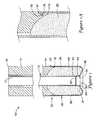
- FIGS. 7A and 7Billustrates the dissolvable closure device in accordance with an embodiment of the present invention.
- FIG. 7Aillustrates the dissolvable closure device 700 having a dissolvable distal tip 708 , a communication tube 706 attached to the dissolvable distal tip 708 , the communication tube 706 having a lumen 732 , a top 736 and a bottom 734 .
- a sponge 704surrounds the communication tube bottom 734 adjacent the dissolvable distal tip 708 .
- a sponge cover 710is positioned around the sponge 704 and placement tube 702 .
- the dissolvable closure device 700is shown with the sponge 704 located at the blood vessel puncture site 712 . As further discussed below, all or parts of the device 700 may be made of any of the dissolvable materials as disclosed above.
- the dissolvable distal tip 708may include a bleed back entrance port 714 that is in fluid communication with the communication tube 706 . Blood entering the bleed back entrance port 714 may bypass the sponge and be observed by a user out of a bleed back exit port (not shown) at the proximal end 718 of the device.
- the dissolvable distal tip 708 and sponge 704may include clot accelerators as discussed above.
- the dissolvable distal tip 724may be any shape such as the hemisphere as shown in FIG. 7B , a conical taper as shown in FIG. 7A , hyperbolic cone, concave, or similar other shapes.
- the sponge cover 710is an outer covering for the sponge 704 to protect and prevent the sponge 704 from expanding prior to a user positioning the device 700 .
- the sponge cover 710may extend the entire length of the device 700 and out of the skin 722 as shown in FIG. 7A .
- the sponge cover 726may only cover the sponge 704 as shown in FIG. 7B and be positioned similarly as described above with reference to FIGS. 1 and 1 a to provide stability during advancement of the device 700 into the blood vessel lumen 720 .
- the sponge coveris preferably made of an absorbable material.
- the placement tube 702may reside proximally of the sponge and extend proximally far enough to exit the skin 722 . However, the placement tube 702 need not extend out of the skin 722 if made of an absorbable material.
- the sponge 704may be fixed together with the placement tube 702 or the device 700 may be used without the placement tube 702 similar to FIG. 5 described above. If the sponge cover 710 or 726 is made of an absorbable material, it is preferable that the sponge cover 710 or 726 be adhered to or frictionally fixed to the sponge 704 or distal tip 708 or 724 . Additionally, the sponge cover 710 may comprise perforations to accelerate blood infiltration into the sponge.
- a guidewire 716may be received through the communication tube 706 .
- a guidewire 716may not be necessary.
- an access sheath(not shown) commonly used in surgical procedures may be used to position the device through the tissue tract and into the blood vessel lumen.
- the use of the access sheathmay also not be necessary.
- the dissolvable closure device 700is positioned within the blood vessel lumen 720 until blood enters the bleed back entrance port 714 .
- the usermay then withdraw the device 700 until bleed back is no longer observed.
- the device 700may then be accurately positioned at the blood vessel puncture site 712 .
- device 700may vary as illustrated in Examples 1 and 2 below:
- the dissolvable tip 708 or 724 , sponge 704 , and sponge cover 710are made of an absorbable material.
- the communication tube 706 and placement tube 702are made of non-absorbable materials. Once positioned, the communication tube 706 , placement tube 702 , and guidewire 716 are removed while the sponge cover 710 is held stationary. As discussed in connection with FIG. 3 , the dissolvable distal tip 708 and sponge cover 710 may soften and dissolve. This starts the process of sponge 704 expansion which may be positioned within the puncture site 712 as shown in FIG. 7A or may be positioned outside the puncture site 712 (not shown).
- the sponge cover 710may then be cut off (not shown) below the skin 722 or left to dissolve if the sponge cover 710 extends outside the skin 722 .
- the remainders of the sponge cover 710 above the skin 722may be released once the sponge cover 710 is dissolved below the skin 722 .
- the dissolvable tip 702 or 724 , communication tube 702 , and sponge 704are made of an absorbable material.
- the sponge cover 710 and placement tubeare made of non-absorbable materials. Once positioned, the sponge cover 710 of FIG. 7A is removed while the placement tube 702 is held stationary. If the sponge cover 726 of FIG. 7B is used, it does not need to be removed.
- the placement tube 702 and guidewire 716are then removed while the communication tube 702 is held stationary. This starts the process of sponge 704 expansion. As discussed above in connection with FIG. 3 , the dissolvable distal tip 708 may soften and dissolve.
- the sponge 704may then be positioned within the puncture site 712 or may be positioned outside the puncture site 712 (not shown).
- the usermay reposition the device 700 using the communication tube 702 at any time.
- the communication tube 702may be cut off below the skin 722 or left in place to dissolve. The remainders of the communication tube 702 above the skin 722 may be released once the communication tube 702 is dissolved below the skin 722 .
- the operatormay apply pressure over the blood vessel puncture site 712 .
- the operatormay then apply diffuse external pressure to the tissue over the sponge 704 .
- the Examplesare merely for illustration purposes and are not meant to limit the present invention.
- FIG. 8is an illustration of a dissolvable tip for use with the dissolvable closure device of the present invention.
- the dissolvable tip 800has a diameter D, a bleed back entrance port 802 having a diameter greater than or equal to 50% of diameter D, and a finger 804 . Additional details of bleed back entrance port 802 and finger 804 are discussed further in co-pending patent application Ser. No. 10/462,065 which is incorporated herein by reference and will not be discussed in the present application.
- the bleed back entrance port 802is in fluid communication with a communication tube 806 .
- the dissolvable tip 800 and communication tube 806are attached and are preferably made of an absorbable material and may be used as similarly described in Example 2 above.
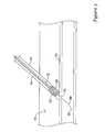
- FIG. 9is an illustration of the dissolvable closure device in accordance with another embodiment of the present invention.
- the device 900has a communication tube 902 having a lumen 920 , a top 904 and a bottom 906 .
- a sponge 910is positioned around the communication tube bottom 906 , having a first end 922 and a second end 924 .
- a sponge cover 912is positioned around the sponge 910 and communication tube bottom 906 thereby forming a hollow distal tip cavity 914 at the sponge first end 922 .
- FIG. 9is illustrated with the use of a placement tube 908 , however, the device 900 may be used without the placement tube 908 similar to FIG. 5 described above.
- the spongemay be adhered to or frictionally fixed to the communication tube 902 and sponge cover 912 with gelatin, an absorbable adhesive, or any other materials as discussed above. Additionally, the sponge cover 912 may comprise perforations to accelerate blood infiltration into the sponge. Furthermore, the sponge cover may be similar in shape to the covers described in co-pending U.S. patent application Ser. No. 10/460,859 filed Jun. 12, 2003, by inventors Mark Ashby and Tin Tran, entitled “Hemostatic Device Including A Capsule”, which is herein incorporated by reference in its entirety.
- the hollow distal tip cavity 914 and sponge 704may include clot accelerators as discussed above.
- the hollow distal tip cavity 914may be any shape such as the hemisphere as shown in FIG. 9 , a conical taper as shown in FIG. 7A , hyperbolic cone, concave, or similar other shapes.
- the hollow distal tip cavity 914may include the bleed back entrance hole 916 as shown in FIG. 9 or the bleed back entrance hole 802 as shown in FIG. 8 .
- the hollow distal tip cavity 914may comprise the finger 804 as illustrated in FIG. 8 .
- the dissolvable closure device 900may extend beyond the patient's skin 926 , or extend below the skin 926 . In use, the device 900 may be used similarly as described in Example 1 and 2 above.
- a guidewire 914may be used and may be positioned through the communication tube 910 . However, the use of a guidewire 914 may not be necessary. Additionally, an access sheath (not shown) commonly used in surgical procedures may be used to position the device through the tissue tract and into the blood vessel lumen. However, the use of the access sheath may not be necessary.
- Sponges used in the present inventionmay be about 1 cm-4 cm in length and preferably 1 cm-2 cm in length.
- the sponge materialshould be chosen to absorb quickly, within 30 seconds to one hour. However, longer absorption times, such as within 90 days or more, will also be possible if desired. However, the longer absorption times may limit re-access to the puncture site, if re-access is necessary. Furthermore, it may be beneficial if the sponge covering, dissolvable distal tip, communication tube, and placement tube dissolve (if made of an absorbable material) quickly enough to release the sponge within 30 seconds to 5 minutes. However, longer dissolution times may be used if desired.
- the diameter of device 700 , 800 or 900may be about 2 F-25 F, and preferably 4 F-20 F. However, the diameter may be equal to the inner diameter of an access sheath, if used. It will further be appreciated that the diameter may be equal to the outer diameter of an access sheath, if the access sheath is not used, to provide for proper blood control of the puncture site.
- dissolvable tip and sponge of the above embodimentsremain stationary after proper placement of the device. It is appreciated that the embodiments of the dissolvable distal tip, such as the finger 804 and bleed back entrance port 802 are provided to assist in retention of the device, rather than to hold the dissolvable tip and sponge in proper position.
Landscapes
- Health & Medical Sciences (AREA)
- Surgery (AREA)
- Life Sciences & Earth Sciences (AREA)
- Public Health (AREA)
- Heart & Thoracic Surgery (AREA)
- Veterinary Medicine (AREA)
- Animal Behavior & Ethology (AREA)
- General Health & Medical Sciences (AREA)
- Epidemiology (AREA)
- Vascular Medicine (AREA)
- Cardiology (AREA)
- Nuclear Medicine, Radiotherapy & Molecular Imaging (AREA)
- Engineering & Computer Science (AREA)
- Biomedical Technology (AREA)
- Medical Informatics (AREA)
- Molecular Biology (AREA)
- Chemical & Material Sciences (AREA)
- Dispersion Chemistry (AREA)
- Materials For Medical Uses (AREA)
Abstract
Description
Claims (27)
Priority Applications (2)
| Application Number | Priority Date | Filing Date | Title |
|---|---|---|---|
| US10/461,587US7955353B1 (en) | 2002-11-04 | 2003-06-12 | Dissolvable closure device |
| US10/462,064US8317821B1 (en) | 2002-11-04 | 2003-06-12 | Release mechanism |
Applications Claiming Priority (2)
| Application Number | Priority Date | Filing Date | Title |
|---|---|---|---|
| US10/287,922US7455680B1 (en) | 2002-11-04 | 2002-11-04 | Apparatus and method for inhibiting blood loss |
| US10/461,587US7955353B1 (en) | 2002-11-04 | 2003-06-12 | Dissolvable closure device |
Related Parent Applications (1)
| Application Number | Title | Priority Date | Filing Date |
|---|---|---|---|
| US10/287,922Continuation-In-PartUS7455680B1 (en) | 2002-11-04 | 2002-11-04 | Apparatus and method for inhibiting blood loss |
Related Child Applications (1)
| Application Number | Title | Priority Date | Filing Date |
|---|---|---|---|
| US10/462,065Continuation-In-PartUS7695492B1 (en) | 1999-09-23 | 2003-06-12 | Enhanced bleed back system |
Publications (1)
| Publication Number | Publication Date |
|---|---|
| US7955353B1true US7955353B1 (en) | 2011-06-07 |
Family
ID=44070836
Family Applications (1)
| Application Number | Title | Priority Date | Filing Date |
|---|---|---|---|
| US10/461,587Expired - Fee RelatedUS7955353B1 (en) | 2002-11-04 | 2003-06-12 | Dissolvable closure device |
Country Status (1)
| Country | Link |
|---|---|
| US (1) | US7955353B1 (en) |
Cited By (13)
| Publication number | Priority date | Publication date | Assignee | Title |
|---|---|---|---|---|
| US20080097521A1 (en)* | 2004-11-05 | 2008-04-24 | Accessclosure, Inc. | Apparatus and methods for sealing a vascular puncture |
| US20120310275A1 (en)* | 2009-08-24 | 2012-12-06 | St. Jude Medical Puerto Rico Llc | Single piece, dual component sealing pad and methods |
| US8382797B2 (en) | 2006-09-13 | 2013-02-26 | Accessclosure, Inc. | Methods for sealing a vascular puncture |
| US8524270B2 (en) | 2001-03-12 | 2013-09-03 | Boston Scientific Scimed, Inc. | Cross-linked gelatin composition coated with a wetting agent |
| WO2014031260A1 (en)* | 2012-08-21 | 2014-02-27 | St. Jude Medical Puerto Rico Llc | Carrier tubes for closure devices |
| US8721680B2 (en) | 2012-03-23 | 2014-05-13 | Accessclosure, Inc. | Apparatus and methods for sealing a vascular puncture |
| US9364206B2 (en) | 2008-04-04 | 2016-06-14 | Access Closure, Inc. | Apparatus and methods for sealing a vascular puncture |
| US9386968B2 (en) | 2011-05-11 | 2016-07-12 | Access Closure, Inc. | Apparatus and methods for sealing a vascular puncture |
| US9713462B2 (en) | 2008-11-12 | 2017-07-25 | Accessclosure, Inc. | Apparatus and methods for sealing a vascular puncture |
| US9757105B2 (en) | 2012-03-23 | 2017-09-12 | Accessclosure, Inc. | Apparatus and methods for sealing a vascular puncture |
| US10595838B2 (en) | 2008-04-04 | 2020-03-24 | Accessclosure, Inc. | Apparatus and methods for sealing a vascular puncture |
| CN114948048A (en)* | 2022-04-29 | 2022-08-30 | 中国人民解放军总医院第四医学中心 | War wound visceral hemorrhage hemostasis device and using method thereof |
| WO2025137297A1 (en)* | 2023-12-20 | 2025-06-26 | Boston Scientific Scimed, Inc. | Controlled shielding of shape memory polymers and foams |
Citations (120)
| Publication number | Priority date | Publication date | Assignee | Title |
|---|---|---|---|---|
| US581235A (en) | 1897-04-20 | Island | ||
| US1578517A (en) | 1924-12-23 | 1926-03-30 | George N Hein | Valve piston and barrel construction for hypodermic syringes |
| US2086580A (en) | 1935-06-24 | 1937-07-13 | Myron C Shirley | Applicator |
| US2465357A (en) | 1944-08-14 | 1949-03-29 | Upjohn Co | Therapeutic sponge and method of making |
| US2492458A (en) | 1944-12-08 | 1949-12-27 | Jr Edgar A Bering | Fibrin foam |
| US2507244A (en) | 1947-04-14 | 1950-05-09 | Upjohn Co | Surgical gelatin dusting powder and process for preparing same |
| US2558395A (en) | 1947-06-03 | 1951-06-26 | Hoffmann La Roche | Undenatured gelatin hemostatic sponge containing thrombin |
| US2597011A (en) | 1950-07-28 | 1952-05-20 | Us Agriculture | Preparation of starch sponge |
| US2680442A (en) | 1952-04-04 | 1954-06-08 | Frank L Linzmayer | Disposable suppository casing |
| US2761446A (en) | 1955-03-30 | 1956-09-04 | Chemical Specialties Co Inc | Implanter and cartridge |
| US2814294A (en) | 1953-04-17 | 1957-11-26 | Becton Dickinson Co | Unit for and method of inhibiting and controlling bleeding tendencies |
| US2824092A (en) | 1955-01-04 | 1958-02-18 | Robert E Thompson | Process of preparation of a gelatincarboxymethyl cellulose complex |
| US2899362A (en) | 1959-08-11 | Hemostatic sponges and method of | ||
| US3157524A (en) | 1960-10-25 | 1964-11-17 | Ethicon Inc | Preparation of collagen sponge |
| US3724465A (en) | 1971-07-22 | 1973-04-03 | Kimberly Clark Co | Tampon coated with insertion aid and method for coating |
| US4000741A (en) | 1975-11-03 | 1977-01-04 | The Kendall Company | Syringe assembly |
| US4077409A (en) | 1974-01-24 | 1978-03-07 | Murray Jerome L | Encapsulated catamenial device |
| GB1509023A (en) | 1973-02-12 | 1978-04-26 | Ochsner Med Found Alton | Septal defect closure apparatus |
| GB1569660A (en) | 1976-07-30 | 1980-06-18 | Medline Ab | Occlusion of body channels |
| US4211323A (en) | 1978-12-01 | 1980-07-08 | California Medical Developments, Inc. | Disposable diagnostic swab having a stored culture medium |
| US4218155A (en) | 1978-02-10 | 1980-08-19 | Etablissements Armor, S.A. | Stick for applying a liquid |
| SU782814A1 (en) | 1977-01-18 | 1980-11-30 | За витель | Prosthesis for closing defect in heart tissues |
| US4238480A (en) | 1978-05-19 | 1980-12-09 | Sawyer Philip Nicholas | Method for preparing an improved hemostatic agent and method of employing the same |
| US4292972A (en) | 1980-07-09 | 1981-10-06 | E. R. Squibb & Sons, Inc. | Lyophilized hydrocolloio foam |
| US4323072A (en) | 1980-01-18 | 1982-04-06 | Shiley, Incorporated | Cannula for a vein distention system |
| US4340066A (en) | 1980-02-01 | 1982-07-20 | Sherwood Medical Industries Inc. | Medical device for collecting a body sample |
| US4390018A (en) | 1980-09-15 | 1983-06-28 | Zukowski Henry J | Method for preventing loss of spinal fluid after spinal tap |
| US4404970A (en) | 1978-05-19 | 1983-09-20 | Sawyer Philip Nicholas | Hemostatic article and methods for preparing and employing the same |
| US4515637A (en) | 1983-11-16 | 1985-05-07 | Seton Company | Collagen-thrombin compositions |
| US4588395A (en) | 1978-03-10 | 1986-05-13 | Lemelson Jerome H | Catheter and method |
| US4587969A (en) | 1985-01-28 | 1986-05-13 | Rolando Gillis | Support assembly for a blood vessel or like organ |
| US4619913A (en) | 1984-05-29 | 1986-10-28 | Matrix Pharmaceuticals, Inc. | Treatments employing drug-containing matrices for introduction into cellular lesion areas |
| US4619261A (en) | 1984-08-09 | 1986-10-28 | Frederico Guerriero | Hydrostatic pressure device for bleeding control through an inflatable, stitchable and retrievable balloon-net system |
| US4645488A (en) | 1982-08-12 | 1987-02-24 | Board Of Trustees Of The University Of Alabama | Syringe for extrusion of wetted, particulate material |
| US4708718A (en) | 1985-07-02 | 1987-11-24 | Target Therapeutics | Hyperthermic treatment of tumors |
| US4744364A (en) | 1987-02-17 | 1988-05-17 | Intravascular Surgical Instruments, Inc. | Device for sealing percutaneous puncture in a vessel |
| US4790819A (en) | 1987-08-24 | 1988-12-13 | American Cyanamid Company | Fibrin clot delivery device and method |
| US4829994A (en) | 1987-05-27 | 1989-05-16 | Kurth Paul A | Femoral compression device for post-catheterization hemostasis |
| US4850960A (en) | 1987-07-08 | 1989-07-25 | Joseph Grayzel | Diagonally tapered, bevelled tip introducing catheter and sheath and method for insertion |
| US4852568A (en) | 1987-02-17 | 1989-08-01 | Kensey Nash Corporation | Method and apparatus for sealing an opening in tissue of a living being |
| US4869143A (en) | 1985-06-11 | 1989-09-26 | Merrick Industries, Inc. | Card file punch |
| US4890612A (en) | 1987-02-17 | 1990-01-02 | Kensey Nash Corporation | Device for sealing percutaneous puncture in a vessel |
| US4900303A (en) | 1978-03-10 | 1990-02-13 | Lemelson Jerome H | Dispensing catheter and method |
| US4929246A (en) | 1988-10-27 | 1990-05-29 | C. R. Bard, Inc. | Method for closing and sealing an artery after removing a catheter |
| US4936835A (en) | 1988-05-26 | 1990-06-26 | Haaga John R | Medical needle with bioabsorbable tip |
| US4950234A (en) | 1987-05-26 | 1990-08-21 | Sumitomo Pharmaceuticals Company, Limited | Device for administering solid preparations |
| US5007895A (en) | 1989-04-05 | 1991-04-16 | Burnett George S | Wound packing instrument |
| US5021059A (en) | 1990-05-07 | 1991-06-04 | Kensey Nash Corporation | Plug device with pulley for sealing punctures in tissue and methods of use |
| US5053046A (en) | 1988-08-22 | 1991-10-01 | Woodrow W. Janese | Dural sealing needle and method of use |
| US5061274A (en) | 1989-12-04 | 1991-10-29 | Kensey Nash Corporation | Plug device for sealing openings and method of use |
| US5080655A (en) | 1988-05-26 | 1992-01-14 | Haaga John R | Medical biopsy needle |
| EP0476178A1 (en) | 1990-09-21 | 1992-03-25 | Bioplex Medical B.V. | Device for placing styptic material on perforated blood vessels |
| US5108421A (en) | 1990-10-01 | 1992-04-28 | Quinton Instrument Company | Insertion assembly and method of inserting a vessel plug into the body of a patient |
| US5163904A (en) | 1991-11-12 | 1992-11-17 | Merit Medical Systems, Inc. | Syringe apparatus with attached pressure gauge |
| US5167624A (en) | 1990-11-09 | 1992-12-01 | Catheter Research, Inc. | Embolus delivery system and method |
| US5192300A (en) | 1990-10-01 | 1993-03-09 | Quinton Instrument Company | Insertion assembly and method of inserting a vessel plug into the body of a patient |
| US5192301A (en) | 1989-01-17 | 1993-03-09 | Nippon Zeon Co., Ltd. | Closing plug of a defect for medical use and a closing plug device utilizing it |
| US5195988A (en) | 1988-05-26 | 1993-03-23 | Haaga John R | Medical needle with removable sheath |
| US5221259A (en) | 1990-12-27 | 1993-06-22 | Novoste Corporation | Wound treating device and method of using same |
| US5220926A (en) | 1992-07-13 | 1993-06-22 | Jones George T | Finger mounted core biopsy guide |
| EP0557963A1 (en) | 1992-02-24 | 1993-09-01 | United States Surgical Corporation | Resilient arm mesh deployer |
| US5242683A (en) | 1989-07-21 | 1993-09-07 | Nycomed Imaging As | Contrast media comprising a paramagnetic agent and an iodinated agent for x-ray and mri |
| US5254105A (en)* | 1988-05-26 | 1993-10-19 | Haaga John R | Sheath for wound closure caused by a medical tubular device |
| US5282827A (en) | 1991-11-08 | 1994-02-01 | Kensey Nash Corporation | Hemostatic puncture closure system and method of use |
| US5290310A (en)* | 1991-10-30 | 1994-03-01 | Howmedica, Inc. | Hemostatic implant introducer |
| US5310407A (en) | 1991-06-17 | 1994-05-10 | Datascope Investment Corp. | Laparoscopic hemostat delivery system and method for using said system |
| US5322515A (en) | 1993-03-15 | 1994-06-21 | Abbott Laboratories | Luer adapter assembly for emergency syringe |
| US5325857A (en) | 1993-07-09 | 1994-07-05 | Hossein Nabai | Skin biopsy device and method |
| US5334216A (en) | 1992-12-10 | 1994-08-02 | Howmedica Inc. | Hemostatic plug |
| US5366480A (en) | 1990-12-24 | 1994-11-22 | American Cyanamid Company | Synthetic elastomeric buttressing pledget |
| US5370656A (en) | 1993-02-26 | 1994-12-06 | Merocel Corporation | Throat pack |
| US5383899A (en) | 1993-09-28 | 1995-01-24 | Hammerslag; Julius G. | Method of using a surface opening adhesive sealer |
| US5383896A (en) | 1993-05-25 | 1995-01-24 | Gershony; Gary | Vascular sealing device |
| US5385550A (en) | 1994-03-29 | 1995-01-31 | Su; Chan-Ho | Needle protective means for prevention against stab and virus infection |
| EP0637431A1 (en) | 1993-08-05 | 1995-02-08 | VODA, Jan | Suture device |
| US5388588A (en) | 1993-05-04 | 1995-02-14 | Nabai; Hossein | Biopsy wound closure device and method |
| US5391183A (en) | 1990-09-21 | 1995-02-21 | Datascope Investment Corp | Device and method sealing puncture wounds |
| US5417699A (en) | 1992-12-10 | 1995-05-23 | Perclose Incorporated | Device and method for the percutaneous suturing of a vascular puncture site |
| US5419765A (en) | 1990-12-27 | 1995-05-30 | Novoste Corporation | Wound treating device and method for treating wounds |
| US5431639A (en) | 1993-08-12 | 1995-07-11 | Boston Scientific Corporation | Treating wounds caused by medical procedures |
| US5437292A (en) | 1993-11-19 | 1995-08-01 | Bioseal, Llc | Method for sealing blood vessel puncture sites |
| US5443481A (en) | 1992-07-27 | 1995-08-22 | Lee; Benjamin I. | Methods and device for percutaneous sealing of arterial puncture sites |
| US5486195A (en) | 1993-07-26 | 1996-01-23 | Myers; Gene | Method and apparatus for arteriotomy closure |
| US5490736A (en) | 1994-09-08 | 1996-02-13 | Habley Medical Technology Corporation | Stylus applicator for a rehydrated multi-constituent medication |
| US5507279A (en) | 1993-11-30 | 1996-04-16 | Fortune; John B. | Retrograde endotracheal intubation kit |
| US5522850A (en) | 1994-06-23 | 1996-06-04 | Incontrol, Inc. | Defibrillation and method for cardioverting a heart and storing related activity data |
| US5522840A (en) | 1992-11-23 | 1996-06-04 | Krajicek; Milan | Device for the non-surgical seal of the interstice in the wall of a vessel |
| US5527332A (en) | 1994-11-02 | 1996-06-18 | Mectra Labs, Inc. | Tissue cutter for surgery |
| US5526822A (en) | 1994-03-24 | 1996-06-18 | Biopsys Medical, Inc. | Method and apparatus for automated biopsy and collection of soft tissue |
| US5540715A (en) | 1992-07-16 | 1996-07-30 | Sherwood Medical Company | Device for sealing hemostatic incisions |
| US5542914A (en) | 1993-02-12 | 1996-08-06 | Kimberly-Clark Corporation | Encapsulated tampon with an applicator |
| US5545178A (en) | 1994-04-29 | 1996-08-13 | Kensey Nash Corporation | System for closing a percutaneous puncture formed by a trocar to prevent tissue at the puncture from herniating |
| US5554108A (en) | 1991-11-06 | 1996-09-10 | Tambrands Inc. | Sanitary tampon |
| US5558853A (en) | 1993-01-25 | 1996-09-24 | Sonus Pharmaceuticals | Phase shift colloids as ultrasound contrast agents |
| US5601603A (en) | 1993-06-16 | 1997-02-11 | White Spot Ag | Use of and process for the introduction of fibrin sealant into a puncture channel |
| US5645566A (en) | 1995-09-15 | 1997-07-08 | Sub Q Inc. | Apparatus and method for percutaneous sealing of blood vessel punctures |
| US5649547A (en) | 1994-03-24 | 1997-07-22 | Biopsys Medical, Inc. | Methods and devices for automated biopsy and collection of soft tissue |
| US5653730A (en) | 1993-09-28 | 1997-08-05 | Hemodynamics, Inc. | Surface opening adhesive sealer |
| US5676689A (en) | 1991-11-08 | 1997-10-14 | Kensey Nash Corporation | Hemostatic puncture closure system including vessel location device and method of use |
| US5681279A (en) | 1996-11-04 | 1997-10-28 | Roper; David H. | Pill dispensing syringe |
| US5769086A (en) | 1995-12-06 | 1998-06-23 | Biopsys Medical, Inc. | Control system and method for automated biopsy device |
| US5769813A (en) | 1995-06-07 | 1998-06-23 | Peiler; Frances K. | Indicator tampon applicator |
| US5782861A (en) | 1996-12-23 | 1998-07-21 | Sub Q Inc. | Percutaneous hemostasis device |
| US5800389A (en) | 1996-02-09 | 1998-09-01 | Emx, Inc. | Biopsy device |
| US5810806A (en) | 1996-08-29 | 1998-09-22 | Ethicon Endo-Surgery | Methods and devices for collection of soft tissue |
| US5858008A (en) | 1997-04-22 | 1999-01-12 | Becton, Dickinson And Company | Cannula sealing shield assembly |
| US5868762A (en) | 1997-09-25 | 1999-02-09 | Sub-Q, Inc. | Percutaneous hemostatic suturing device and method |
| US5902310A (en) | 1996-08-12 | 1999-05-11 | Ethicon Endo-Surgery, Inc. | Apparatus and method for marking tissue |
| US6027482A (en) | 1994-12-12 | 2000-02-22 | Becton Dickinson And Company | Syringe tip cap |
| US6027471A (en) | 1995-01-18 | 2000-02-22 | Fallon; Timothy J. | Apparatus for applying a hemostatic agent onto a tissue |
| US6071301A (en) | 1998-05-01 | 2000-06-06 | Sub Q., Inc. | Device and method for facilitating hemostasis of a biopsy tract |
| US6071300A (en) | 1995-09-15 | 2000-06-06 | Sub-Q Inc. | Apparatus and method for percutaneous sealing of blood vessel punctures |
| US6161034A (en) | 1999-02-02 | 2000-12-12 | Senorx, Inc. | Methods and chemical preparations for time-limited marking of biopsy sites |
| US6162192A (en) | 1998-05-01 | 2000-12-19 | Sub Q, Inc. | System and method for facilitating hemostasis of blood vessel punctures with absorbable sponge |
| US6183497B1 (en) | 1998-05-01 | 2001-02-06 | Sub-Q, Inc. | Absorbable sponge with contrasting agent |
| US6200328B1 (en) | 1998-05-01 | 2001-03-13 | Sub Q, Incorporated | Device and method for facilitating hemostasis of a biopsy tract |
| US6315753B1 (en) | 1998-05-01 | 2001-11-13 | Sub-Q, Inc. | System and method for facilitating hemostasis of blood vessel punctures with absorbable sponge |
| US6610025B2 (en) | 2001-08-06 | 2003-08-26 | The Procter & Gamble Company | Tampon applicator arrangement |
| US6984219B2 (en) | 1999-09-23 | 2006-01-10 | Mark Ashby | Depth and puncture control for blood vessel hemostasis system |
| US7156880B2 (en)* | 2002-06-13 | 2007-01-02 | Kensey Nash Corporation | Devices and methods for treating defects in the tissue of a living being |
- 2003
- 2003-06-12USUS10/461,587patent/US7955353B1/ennot_activeExpired - Fee Related
Patent Citations (143)
| Publication number | Priority date | Publication date | Assignee | Title |
|---|---|---|---|---|
| US2899362A (en) | 1959-08-11 | Hemostatic sponges and method of | ||
| US581235A (en) | 1897-04-20 | Island | ||
| US1578517A (en) | 1924-12-23 | 1926-03-30 | George N Hein | Valve piston and barrel construction for hypodermic syringes |
| US2086580A (en) | 1935-06-24 | 1937-07-13 | Myron C Shirley | Applicator |
| US2465357A (en) | 1944-08-14 | 1949-03-29 | Upjohn Co | Therapeutic sponge and method of making |
| US2492458A (en) | 1944-12-08 | 1949-12-27 | Jr Edgar A Bering | Fibrin foam |
| US2507244A (en) | 1947-04-14 | 1950-05-09 | Upjohn Co | Surgical gelatin dusting powder and process for preparing same |
| US2558395A (en) | 1947-06-03 | 1951-06-26 | Hoffmann La Roche | Undenatured gelatin hemostatic sponge containing thrombin |
| US2597011A (en) | 1950-07-28 | 1952-05-20 | Us Agriculture | Preparation of starch sponge |
| US2680442A (en) | 1952-04-04 | 1954-06-08 | Frank L Linzmayer | Disposable suppository casing |
| US2814294A (en) | 1953-04-17 | 1957-11-26 | Becton Dickinson Co | Unit for and method of inhibiting and controlling bleeding tendencies |
| US2824092A (en) | 1955-01-04 | 1958-02-18 | Robert E Thompson | Process of preparation of a gelatincarboxymethyl cellulose complex |
| US2761446A (en) | 1955-03-30 | 1956-09-04 | Chemical Specialties Co Inc | Implanter and cartridge |
| US3157524A (en) | 1960-10-25 | 1964-11-17 | Ethicon Inc | Preparation of collagen sponge |
| US3724465A (en) | 1971-07-22 | 1973-04-03 | Kimberly Clark Co | Tampon coated with insertion aid and method for coating |
| GB1509023A (en) | 1973-02-12 | 1978-04-26 | Ochsner Med Found Alton | Septal defect closure apparatus |
| US4077409A (en) | 1974-01-24 | 1978-03-07 | Murray Jerome L | Encapsulated catamenial device |
| US4000741A (en) | 1975-11-03 | 1977-01-04 | The Kendall Company | Syringe assembly |
| GB1569660A (en) | 1976-07-30 | 1980-06-18 | Medline Ab | Occlusion of body channels |
| SU782814A1 (en) | 1977-01-18 | 1980-11-30 | За витель | Prosthesis for closing defect in heart tissues |
| US4218155A (en) | 1978-02-10 | 1980-08-19 | Etablissements Armor, S.A. | Stick for applying a liquid |
| US4900303A (en) | 1978-03-10 | 1990-02-13 | Lemelson Jerome H | Dispensing catheter and method |
| US4588395A (en) | 1978-03-10 | 1986-05-13 | Lemelson Jerome H | Catheter and method |
| US4238480A (en) | 1978-05-19 | 1980-12-09 | Sawyer Philip Nicholas | Method for preparing an improved hemostatic agent and method of employing the same |
| US4404970A (en) | 1978-05-19 | 1983-09-20 | Sawyer Philip Nicholas | Hemostatic article and methods for preparing and employing the same |
| US4211323A (en) | 1978-12-01 | 1980-07-08 | California Medical Developments, Inc. | Disposable diagnostic swab having a stored culture medium |
| EP0032826B1 (en) | 1980-01-18 | 1984-06-20 | Shiley Incorporated | Vein distention apparatus |
| US4323072A (en) | 1980-01-18 | 1982-04-06 | Shiley, Incorporated | Cannula for a vein distention system |
| US4340066A (en) | 1980-02-01 | 1982-07-20 | Sherwood Medical Industries Inc. | Medical device for collecting a body sample |
| US4292972A (en) | 1980-07-09 | 1981-10-06 | E. R. Squibb & Sons, Inc. | Lyophilized hydrocolloio foam |
| US4390018A (en) | 1980-09-15 | 1983-06-28 | Zukowski Henry J | Method for preventing loss of spinal fluid after spinal tap |
| US4645488A (en) | 1982-08-12 | 1987-02-24 | Board Of Trustees Of The University Of Alabama | Syringe for extrusion of wetted, particulate material |
| US4515637A (en) | 1983-11-16 | 1985-05-07 | Seton Company | Collagen-thrombin compositions |
| US4619913A (en) | 1984-05-29 | 1986-10-28 | Matrix Pharmaceuticals, Inc. | Treatments employing drug-containing matrices for introduction into cellular lesion areas |
| US4619261A (en) | 1984-08-09 | 1986-10-28 | Frederico Guerriero | Hydrostatic pressure device for bleeding control through an inflatable, stitchable and retrievable balloon-net system |
| US4587969A (en) | 1985-01-28 | 1986-05-13 | Rolando Gillis | Support assembly for a blood vessel or like organ |
| US4869143A (en) | 1985-06-11 | 1989-09-26 | Merrick Industries, Inc. | Card file punch |
| US4708718A (en) | 1985-07-02 | 1987-11-24 | Target Therapeutics | Hyperthermic treatment of tumors |
| US4852568A (en) | 1987-02-17 | 1989-08-01 | Kensey Nash Corporation | Method and apparatus for sealing an opening in tissue of a living being |
| US4744364A (en) | 1987-02-17 | 1988-05-17 | Intravascular Surgical Instruments, Inc. | Device for sealing percutaneous puncture in a vessel |
| US4890612A (en) | 1987-02-17 | 1990-01-02 | Kensey Nash Corporation | Device for sealing percutaneous puncture in a vessel |
| US4950234A (en) | 1987-05-26 | 1990-08-21 | Sumitomo Pharmaceuticals Company, Limited | Device for administering solid preparations |
| US4829994A (en) | 1987-05-27 | 1989-05-16 | Kurth Paul A | Femoral compression device for post-catheterization hemostasis |
| US4850960A (en) | 1987-07-08 | 1989-07-25 | Joseph Grayzel | Diagonally tapered, bevelled tip introducing catheter and sheath and method for insertion |
| US4790819A (en) | 1987-08-24 | 1988-12-13 | American Cyanamid Company | Fibrin clot delivery device and method |
| US5080655A (en) | 1988-05-26 | 1992-01-14 | Haaga John R | Medical biopsy needle |
| US4936835A (en) | 1988-05-26 | 1990-06-26 | Haaga John R | Medical needle with bioabsorbable tip |
| US5195988A (en) | 1988-05-26 | 1993-03-23 | Haaga John R | Medical needle with removable sheath |
| US5254105A (en)* | 1988-05-26 | 1993-10-19 | Haaga John R | Sheath for wound closure caused by a medical tubular device |
| US5053046A (en) | 1988-08-22 | 1991-10-01 | Woodrow W. Janese | Dural sealing needle and method of use |
| US4929246A (en) | 1988-10-27 | 1990-05-29 | C. R. Bard, Inc. | Method for closing and sealing an artery after removing a catheter |
| US5192301A (en) | 1989-01-17 | 1993-03-09 | Nippon Zeon Co., Ltd. | Closing plug of a defect for medical use and a closing plug device utilizing it |
| FR2641692B1 (en) | 1989-01-17 | 1995-05-12 | Nippon Zeon Co | |
| US5007895A (en) | 1989-04-05 | 1991-04-16 | Burnett George S | Wound packing instrument |
| US5242683A (en) | 1989-07-21 | 1993-09-07 | Nycomed Imaging As | Contrast media comprising a paramagnetic agent and an iodinated agent for x-ray and mri |
| US5061274A (en) | 1989-12-04 | 1991-10-29 | Kensey Nash Corporation | Plug device for sealing openings and method of use |
| US5021059A (en) | 1990-05-07 | 1991-06-04 | Kensey Nash Corporation | Plug device with pulley for sealing punctures in tissue and methods of use |
| US5591204A (en) | 1990-09-21 | 1997-01-07 | Datascope Investment Corp. | Device and method for sealing puncture wounds |
| EP0482350B1 (en) | 1990-09-21 | 1996-12-27 | Datascope Investment Corp. | Device for sealing puncture wounds |
| US5725498A (en) | 1990-09-21 | 1998-03-10 | Datascope Investment Corp. | Device and method for sealing puncture wounds |
| US5741223A (en) | 1990-09-21 | 1998-04-21 | Datascope Investment Corp. | Device and method for sealing puncture wounds |
| US5830130A (en) | 1990-09-21 | 1998-11-03 | Datascope Investment Corp. | Device and method for sealing puncture wounds |
| EP0476178A1 (en) | 1990-09-21 | 1992-03-25 | Bioplex Medical B.V. | Device for placing styptic material on perforated blood vessels |
| US5437631A (en) | 1990-09-21 | 1995-08-01 | Datascope Investment Corp. | Percutaneous introducer set and method for sealing puncture wounds |
| US5391183A (en) | 1990-09-21 | 1995-02-21 | Datascope Investment Corp | Device and method sealing puncture wounds |
| US5591205A (en) | 1990-10-01 | 1997-01-07 | Quinton Instrument Company | Insertion assembly and method of inserting a vessel plug into the body of a patient |
| US5716375A (en) | 1990-10-01 | 1998-02-10 | Quinton Instrument Company | Insertion assembly and method of inserting a vessel plug into the body of a patient |
| US5108421A (en) | 1990-10-01 | 1992-04-28 | Quinton Instrument Company | Insertion assembly and method of inserting a vessel plug into the body of a patient |
| US5275616A (en) | 1990-10-01 | 1994-01-04 | Quinton Instrument Company | Insertion assembly and method of inserting a vessel plug into the body of a patient |
| US5478352A (en) | 1990-10-01 | 1995-12-26 | Quinton Instrument Company | Insertion assembly and method of inserting a vessel plug into the body of a patient |
| US5601602A (en) | 1990-10-01 | 1997-02-11 | Quinton Instrument Company | Insertion assembly and method of inserting a vessel plug into the body of a patient |
| US5275616B1 (en) | 1990-10-01 | 1996-01-23 | Quinton Instr | Insertion assembly and method of inserting a vessel plug into the body of a patient |
| US5192300A (en) | 1990-10-01 | 1993-03-09 | Quinton Instrument Company | Insertion assembly and method of inserting a vessel plug into the body of a patient |
| US5167624A (en) | 1990-11-09 | 1992-12-01 | Catheter Research, Inc. | Embolus delivery system and method |
| US5366480A (en) | 1990-12-24 | 1994-11-22 | American Cyanamid Company | Synthetic elastomeric buttressing pledget |
| US5419765A (en) | 1990-12-27 | 1995-05-30 | Novoste Corporation | Wound treating device and method for treating wounds |
| US5221259A (en) | 1990-12-27 | 1993-06-22 | Novoste Corporation | Wound treating device and method of using same |
| US5310407A (en) | 1991-06-17 | 1994-05-10 | Datascope Investment Corp. | Laparoscopic hemostat delivery system and method for using said system |
| US5290310A (en)* | 1991-10-30 | 1994-03-01 | Howmedica, Inc. | Hemostatic implant introducer |
| US5324306A (en) | 1991-10-30 | 1994-06-28 | Howmedica, Inc. | Hemostatic implant introducer |
| US5554108A (en) | 1991-11-06 | 1996-09-10 | Tambrands Inc. | Sanitary tampon |
| US5282827A (en) | 1991-11-08 | 1994-02-01 | Kensey Nash Corporation | Hemostatic puncture closure system and method of use |
| US5676689A (en) | 1991-11-08 | 1997-10-14 | Kensey Nash Corporation | Hemostatic puncture closure system including vessel location device and method of use |
| US6007563A (en) | 1991-11-08 | 1999-12-28 | Kensey Nash Corporation | Method of deploying percutaneous puncture closure |
| US5163904A (en) | 1991-11-12 | 1992-11-17 | Merit Medical Systems, Inc. | Syringe apparatus with attached pressure gauge |
| EP0557963A1 (en) | 1992-02-24 | 1993-09-01 | United States Surgical Corporation | Resilient arm mesh deployer |
| US5220926A (en) | 1992-07-13 | 1993-06-22 | Jones George T | Finger mounted core biopsy guide |
| US5540715A (en) | 1992-07-16 | 1996-07-30 | Sherwood Medical Company | Device for sealing hemostatic incisions |
| US5443481A (en) | 1992-07-27 | 1995-08-22 | Lee; Benjamin I. | Methods and device for percutaneous sealing of arterial puncture sites |
| US5522840A (en) | 1992-11-23 | 1996-06-04 | Krajicek; Milan | Device for the non-surgical seal of the interstice in the wall of a vessel |
| US5417699A (en) | 1992-12-10 | 1995-05-23 | Perclose Incorporated | Device and method for the percutaneous suturing of a vascular puncture site |
| US5334216A (en) | 1992-12-10 | 1994-08-02 | Howmedica Inc. | Hemostatic plug |
| US5558853A (en) | 1993-01-25 | 1996-09-24 | Sonus Pharmaceuticals | Phase shift colloids as ultrasound contrast agents |
| US5542914A (en) | 1993-02-12 | 1996-08-06 | Kimberly-Clark Corporation | Encapsulated tampon with an applicator |
| US5370656A (en) | 1993-02-26 | 1994-12-06 | Merocel Corporation | Throat pack |
| US5322515A (en) | 1993-03-15 | 1994-06-21 | Abbott Laboratories | Luer adapter assembly for emergency syringe |
| US5479936A (en) | 1993-05-04 | 1996-01-02 | Nabai; Hossein | Biopsy wound closure device and method |
| US5388588A (en) | 1993-05-04 | 1995-02-14 | Nabai; Hossein | Biopsy wound closure device and method |
| US5467780A (en) | 1993-05-04 | 1995-11-21 | Nabai; Hossein | Biopsy wound closure device and method |
| US5383896A (en) | 1993-05-25 | 1995-01-24 | Gershony; Gary | Vascular sealing device |
| US5601603A (en) | 1993-06-16 | 1997-02-11 | White Spot Ag | Use of and process for the introduction of fibrin sealant into a puncture channel |
| US5325857A (en) | 1993-07-09 | 1994-07-05 | Hossein Nabai | Skin biopsy device and method |
| US5486195A (en) | 1993-07-26 | 1996-01-23 | Myers; Gene | Method and apparatus for arteriotomy closure |
| EP0637431A1 (en) | 1993-08-05 | 1995-02-08 | VODA, Jan | Suture device |
| US5431639A (en) | 1993-08-12 | 1995-07-11 | Boston Scientific Corporation | Treating wounds caused by medical procedures |
| US5653730A (en) | 1993-09-28 | 1997-08-05 | Hemodynamics, Inc. | Surface opening adhesive sealer |
| US5383899A (en) | 1993-09-28 | 1995-01-24 | Hammerslag; Julius G. | Method of using a surface opening adhesive sealer |
| US5529577A (en) | 1993-09-28 | 1996-06-25 | Hemodynamics, Inc. | Surface opening adhesive sealer |
| US5665107A (en) | 1993-09-28 | 1997-09-09 | Hemodynamics, Inc. | Surface opening adhesive sealer |
| US5437292A (en) | 1993-11-19 | 1995-08-01 | Bioseal, Llc | Method for sealing blood vessel puncture sites |
| US5507279A (en) | 1993-11-30 | 1996-04-16 | Fortune; John B. | Retrograde endotracheal intubation kit |
| US5526822A (en) | 1994-03-24 | 1996-06-18 | Biopsys Medical, Inc. | Method and apparatus for automated biopsy and collection of soft tissue |
| US5649547A (en) | 1994-03-24 | 1997-07-22 | Biopsys Medical, Inc. | Methods and devices for automated biopsy and collection of soft tissue |
| US5775333A (en) | 1994-03-24 | 1998-07-07 | Ethicon Endo-Surgery, Inc. | Apparatus for automated biopsy and collection of soft tissue |
| US5385550A (en) | 1994-03-29 | 1995-01-31 | Su; Chan-Ho | Needle protective means for prevention against stab and virus infection |
| US5545178A (en) | 1994-04-29 | 1996-08-13 | Kensey Nash Corporation | System for closing a percutaneous puncture formed by a trocar to prevent tissue at the puncture from herniating |
| US5522850A (en) | 1994-06-23 | 1996-06-04 | Incontrol, Inc. | Defibrillation and method for cardioverting a heart and storing related activity data |
| US5490736A (en) | 1994-09-08 | 1996-02-13 | Habley Medical Technology Corporation | Stylus applicator for a rehydrated multi-constituent medication |
| US5527332A (en) | 1994-11-02 | 1996-06-18 | Mectra Labs, Inc. | Tissue cutter for surgery |
| US6027482A (en) | 1994-12-12 | 2000-02-22 | Becton Dickinson And Company | Syringe tip cap |
| US6027471A (en) | 1995-01-18 | 2000-02-22 | Fallon; Timothy J. | Apparatus for applying a hemostatic agent onto a tissue |
| US5769813A (en) | 1995-06-07 | 1998-06-23 | Peiler; Frances K. | Indicator tampon applicator |
| US6071300A (en) | 1995-09-15 | 2000-06-06 | Sub-Q Inc. | Apparatus and method for percutaneous sealing of blood vessel punctures |
| US5645566A (en) | 1995-09-15 | 1997-07-08 | Sub Q Inc. | Apparatus and method for percutaneous sealing of blood vessel punctures |
| US5769086A (en) | 1995-12-06 | 1998-06-23 | Biopsys Medical, Inc. | Control system and method for automated biopsy device |
| US5800389A (en) | 1996-02-09 | 1998-09-01 | Emx, Inc. | Biopsy device |
| US5902310A (en) | 1996-08-12 | 1999-05-11 | Ethicon Endo-Surgery, Inc. | Apparatus and method for marking tissue |
| US5810806A (en) | 1996-08-29 | 1998-09-22 | Ethicon Endo-Surgery | Methods and devices for collection of soft tissue |
| US5681279A (en) | 1996-11-04 | 1997-10-28 | Roper; David H. | Pill dispensing syringe |
| US5782861A (en) | 1996-12-23 | 1998-07-21 | Sub Q Inc. | Percutaneous hemostasis device |
| US5984950A (en) | 1996-12-23 | 1999-11-16 | Sub-Q, Inc. | Percutaneous hemostasis device |
| US5858008A (en) | 1997-04-22 | 1999-01-12 | Becton, Dickinson And Company | Cannula sealing shield assembly |
| US5868762A (en) | 1997-09-25 | 1999-02-09 | Sub-Q, Inc. | Percutaneous hemostatic suturing device and method |
| US6071301A (en) | 1998-05-01 | 2000-06-06 | Sub Q., Inc. | Device and method for facilitating hemostasis of a biopsy tract |
| US6086607A (en) | 1998-05-01 | 2000-07-11 | Sub-Q, Inc. | Device and method for facilitating hemostasis of a biopsy tract |
| US6162192A (en) | 1998-05-01 | 2000-12-19 | Sub Q, Inc. | System and method for facilitating hemostasis of blood vessel punctures with absorbable sponge |
| US6183497B1 (en) | 1998-05-01 | 2001-02-06 | Sub-Q, Inc. | Absorbable sponge with contrasting agent |
| US6200328B1 (en) | 1998-05-01 | 2001-03-13 | Sub Q, Incorporated | Device and method for facilitating hemostasis of a biopsy tract |
| US6315753B1 (en) | 1998-05-01 | 2001-11-13 | Sub-Q, Inc. | System and method for facilitating hemostasis of blood vessel punctures with absorbable sponge |
| US6161034A (en) | 1999-02-02 | 2000-12-12 | Senorx, Inc. | Methods and chemical preparations for time-limited marking of biopsy sites |
| US6984219B2 (en) | 1999-09-23 | 2006-01-10 | Mark Ashby | Depth and puncture control for blood vessel hemostasis system |
| US6610025B2 (en) | 2001-08-06 | 2003-08-26 | The Procter & Gamble Company | Tampon applicator arrangement |
| US7156880B2 (en)* | 2002-06-13 | 2007-01-02 | Kensey Nash Corporation | Devices and methods for treating defects in the tissue of a living being |
Non-Patent Citations (28)
| Title |
|---|
| Allison, D., et al., "Percutaneous liver biopsy and track embolization with steel coils", Radiology, vol. 169, pp. 261-263, (1998). |
| Chuang, V., et al., "Sheath needle for liver biopsy in high-risk patience", Radiology, vol. 166, pp. 261-262 (1988). |
| Fandrich, C., et al. "Small guage gelfoam plug liver biopsy in high risk patients", Australian Radiology, vol. 40, pp. 230-234 (1996). |
| Foran, JPM, et al. "Early mobilisation after percutaneous cardiac catheterisation using collagen plug (vasoseal) maemostatis" BRHeart, vol. 69, pp. 424-429 (1993). |
| Gibbs, JSR, "Femoral arterial hemostasis" J. Interventional card, vol. 5, pp. 85-88 (1992). |
| J. Bryne Review Article: Endovascular treatments for intracranial anuerysms, 1996 The British journal of radiology; 98,891-899. |
| John T. Correll, et al. Biologic investigations of new absorbable sponge; p. 585. |
| John T. Correll, et al., A new Physiologically absorbable sponge. |
| Journal of interventional cardiology vol. 5 No. 2 June. |
| Kassell, et al. Size of Intracanial aneurysm; vol. 12, No. 3, (1983). |
| Kiemeneiji, F, et al., "Improved anticoagulation management after Palmaz Schatz coronary stent implantation by sealing the arterial puncture site with vascular hemostasis device", Catheterization and Cardiovascular diagnosis, vol. 30, pp. 1685-1692 (1995). |
| Kussmaul, WG, "Rapid arterial hemostasis", J. Am. Coll. Card., vol. 25, pp. 1685-1692 (1995). |
| Pharmacia & Upjohn manufacturer brochure "gelfoam sterile powder", (Feb. 1996). |
| Pharmacia & Upjohn manufacturer brochure (Sep. 1996). |
| Pharmacia & Upjohn manufacturer brochure gelfoam sterile sponge, sterile powder and sterile film, pp. 1-34 (May 1997). |
| Pharmacia & Upjohn manufacturer brochure, "gelfoam sterile powder" (Mar. 1996). |
| Pharmacia & Upjohn manufacturer specification, "Gelfoam sterile sponge, sterile powder and sterile film" pp. 1-23 (Nov. 1996). |
| Riley, SA, Percutaneous liver biopsy with plugging of needle track: a safe method for use in patients with impaired coagulation, The lancet, p. 436 (1964). |
| Sanborn, T. Multicenter randomized trial comparing perutaneous collagen hemostasis device with conventional manual compression after diagnostic angiography and angioplasty , J. Am. Coll. Card., vol. 22, pp. 1273-1279, (1993). |
| Scharader, R. "Collagen appl.", Catheterization & cardiovascular diagnosis (1992) pp. 298-302. |
| Schievink, et al. The new england journal of medicaine; review articles; intracanial aneurysms; Jan. 2, 1997. |
| Silber, S., "Rapid hemostasis of arterial puncture sites with collagen in patients undergoing diagnostic interventional cardiac catherterization", clinical cardiology, vol. 20, pp. 981-992, (1997). |
| Smith, T., "Percutaneous transhepatic liver biopsy with tract embolization", Radiology, vol. 198, pp. 769-774 (1996). |
| Szikora, et al. Combined Use of stents and cells to treat experimental wide-necked carotid aneuryms: Preliminary results; AJNR AM newradiol 15: 1091-1102, Jun. 1994. |
| Szikora, et al. Endovascular treatment of experimental anuerysms with liquid polymers: vol. 38, No. 2, Feb. 1996. |
| Turjman, et al. Combined stent implantation & endosacular coil placement for tretment of experimental wide-necked aneurysms:AJNRAM J. Neuroradio 15: 1087-1090 Jun. 1994. |
| Yoshimoto, et al cerebral anuerysms unrelated to arterial bifurcations; Acta neurochir (Wien) (96) 138: 958-964. |
| Zins, M., "US-guided percutaneous liver biopsy with plugging of the needle track" radiology, vol. 187, pp. 841-843,(1992). |
Cited By (32)
| Publication number | Priority date | Publication date | Assignee | Title |
|---|---|---|---|---|
| US8524270B2 (en) | 2001-03-12 | 2013-09-03 | Boston Scientific Scimed, Inc. | Cross-linked gelatin composition coated with a wetting agent |
| US8821918B2 (en) | 2001-03-12 | 2014-09-02 | Boston Scientific Scimed Inc. | Cross-linked gelatin composition comprising a wetting agent |
| US10149670B2 (en) | 2004-11-05 | 2018-12-11 | Access Closure, Inc. | Apparatus and methods for sealing a vascular puncture |
| US9039735B2 (en) | 2004-11-05 | 2015-05-26 | Access Closure, Inc. | Apparatus and methods for sealing a vascular puncture |
| US20080097521A1 (en)* | 2004-11-05 | 2008-04-24 | Accessclosure, Inc. | Apparatus and methods for sealing a vascular puncture |
| US8951283B2 (en) | 2004-11-05 | 2015-02-10 | Access Closure, Inc. | Apparatus and methods for sealing a vascular puncture |
| US8382797B2 (en) | 2006-09-13 | 2013-02-26 | Accessclosure, Inc. | Methods for sealing a vascular puncture |
| US10213191B2 (en) | 2006-09-13 | 2019-02-26 | Accessclosure, Inc. | Apparatus and methods for sealing a vascular puncture |
| US8382798B2 (en) | 2006-09-13 | 2013-02-26 | Accessclosure, Inc. | Apparatus for sealing a vascular puncture |
| US10595838B2 (en) | 2008-04-04 | 2020-03-24 | Accessclosure, Inc. | Apparatus and methods for sealing a vascular puncture |
| US11925337B2 (en) | 2008-04-04 | 2024-03-12 | Access Closure, Inc. | Apparatus and methods for sealing a vascular puncture |
| US11707265B2 (en) | 2008-04-04 | 2023-07-25 | Access Closure, Inc. | Apparatus and methods for sealing a vascular puncture |
| US9364206B2 (en) | 2008-04-04 | 2016-06-14 | Access Closure, Inc. | Apparatus and methods for sealing a vascular puncture |
| US10512455B2 (en) | 2008-04-04 | 2019-12-24 | Access Closure, Inc. | Apparatus and methods for sealing a vascular puncture |
| US10806438B2 (en) | 2008-11-12 | 2020-10-20 | Access Closure, Inc. | Apparatus and methods for sealing a vascular puncture |
| US9713462B2 (en) | 2008-11-12 | 2017-07-25 | Accessclosure, Inc. | Apparatus and methods for sealing a vascular puncture |
| US11707266B2 (en) | 2008-11-12 | 2023-07-25 | Access Closure, Inc. | Apparatus and methods for sealing a vascular puncture |
| US9820727B2 (en)* | 2009-08-24 | 2017-11-21 | St. Jude Medical Puerto Rico Llc | Single piece, dual component sealing pad and methods |
| US20120310275A1 (en)* | 2009-08-24 | 2012-12-06 | St. Jude Medical Puerto Rico Llc | Single piece, dual component sealing pad and methods |
| US9386968B2 (en) | 2011-05-11 | 2016-07-12 | Access Closure, Inc. | Apparatus and methods for sealing a vascular puncture |
| US11534150B2 (en) | 2011-05-11 | 2022-12-27 | Access Closure, Inc. | Apparatus and methods for sealing a vascular puncture |
| US10314567B2 (en) | 2011-05-11 | 2019-06-11 | Access Closure | Apparatus and methods for sealing a vascular puncture |
| US10499893B2 (en) | 2012-03-23 | 2019-12-10 | Accessclosure, Inc. | Apparatus and methods for sealing a vascular puncture |
| US10245012B2 (en) | 2012-03-23 | 2019-04-02 | Access Closure, Inc. | Apparatus and methods for sealing a vascular puncture |
| US11272911B2 (en) | 2012-03-23 | 2022-03-15 | Access Closure, Inc. | Apparatus and method for sealing a vascular puncture |
| US8721680B2 (en) | 2012-03-23 | 2014-05-13 | Accessclosure, Inc. | Apparatus and methods for sealing a vascular puncture |
| US9757105B2 (en) | 2012-03-23 | 2017-09-12 | Accessclosure, Inc. | Apparatus and methods for sealing a vascular puncture |
| US12144495B2 (en) | 2012-03-23 | 2024-11-19 | Access Closure, Inc. | Apparatus and methods for sealing a vascular puncture |
| WO2014031260A1 (en)* | 2012-08-21 | 2014-02-27 | St. Jude Medical Puerto Rico Llc | Carrier tubes for closure devices |
| US9585643B2 (en) | 2012-08-21 | 2017-03-07 | St. Jude Medical Puerto Rico Llc | Carrier tubes for closure devices |
| CN114948048A (en)* | 2022-04-29 | 2022-08-30 | 中国人民解放军总医院第四医学中心 | War wound visceral hemorrhage hemostasis device and using method thereof |
| WO2025137297A1 (en)* | 2023-12-20 | 2025-06-26 | Boston Scientific Scimed, Inc. | Controlled shielding of shape memory polymers and foams |
Similar Documents
| Publication | Publication Date | Title |
|---|---|---|
| US7455680B1 (en) | Apparatus and method for inhibiting blood loss | |
| EP1807131B1 (en) | Apparatus for sealing a vascular puncture | |
| US8348971B2 (en) | Apparatus and methods for facilitating hemostasis within a vascular puncture | |
| JP4805162B2 (en) | Hemostatic device | |
| US7622628B2 (en) | Hemostatic wire guided bandage and method of use | |
| US6036699A (en) | Device and method for suturing tissue | |
| CA2091890C (en) | Vessel plug insertion assembly and method | |
| CN101495047B (en) | Vascular wound closure device and method | |
| US5192300A (en) | Insertion assembly and method of inserting a vessel plug into the body of a patient | |
| US8709039B2 (en) | Hemostatic devices and methods for use thereof | |
| US7955353B1 (en) | Dissolvable closure device | |
| US20140316377A1 (en) | Hemostatic Devices and Methods For Use Thereof | |
| US20060276836A1 (en) | Hemostatic wire guided bandage and method of use | |
| JP2005534388A (en) | Self trauma seal device | |
| JP2001517472A (en) | Percutaneous hemostatic suturing device and method | |
| JP2005534389A (en) | Device for sealing a puncture hole by reducing the perimeter of the puncture hole | |
| JPH0788114A (en) | Pricking section closing material | |
| US20090270911A1 (en) | Vessel Sealing Device and Method of Using Same |
Legal Events
| Date | Code | Title | Description |
|---|---|---|---|
| AS | Assignment | Owner name:SUB-Q, INC., CALIFORNIA Free format text:ASSIGNMENT OF ASSIGNORS INTEREST;ASSIGNORS:ASHBY, MARK;SING, EDUARDO CHI;TRAN, TIN;REEL/FRAME:014141/0856 Effective date:20030929 | |
| AS | Assignment | Owner name:PVG ASSOCIATES II, L.P., CALIFORNIA Free format text:NOTE AND WARRANT PURCHASE AGREEMENT;ASSIGNOR:SUB-Q, INC.;REEL/FRAME:015156/0484 Effective date:20040831 Owner name:KINGSBURY CAPITAL PARTNERS, L.P. IV, CALIFORNIA Free format text:NOTE AND WARRANT PURCHASE AGREEMENT;ASSIGNOR:SUB-Q, INC.;REEL/FRAME:015156/0484 Effective date:20040831 Owner name:PACIFIC VENTURE GROUP II, L.P., CALIFORNIA Free format text:NOTE AND WARRANT PURCHASE AGREEMENT;ASSIGNOR:SUB-Q, INC.;REEL/FRAME:015156/0484 Effective date:20040831 Owner name:HARTZLER, GEOFFREY O., KANSAS Free format text:NOTE AND WARRANT PURCHASE AGREEMENT;ASSIGNOR:SUB-Q, INC.;REEL/FRAME:015156/0484 Effective date:20040831 Owner name:WALLACE, GEORGE, CALIFORNIA Free format text:NOTE AND WARRANT PURCHASE AGREEMENT;ASSIGNOR:SUB-Q, INC.;REEL/FRAME:015156/0484 Effective date:20040831 Owner name:CRAGG, ANDREW H., MINNESOTA Free format text:NOTE AND WARRANT PURCHASE AGREEMENT;ASSIGNOR:SUB-Q, INC.;REEL/FRAME:015156/0484 Effective date:20040831 Owner name:FEUCHTER, BRUCE, CALIFORNIA Free format text:NOTE AND WARRANT PURCHASE AGREEMENT;ASSIGNOR:SUB-Q, INC.;REEL/FRAME:015156/0484 Effective date:20040831 Owner name:ALLEN FAMILY TRUST DATED 10/12/81, CALIFORNIA Free format text:NOTE AND WARRANT PURCHASE AGREEMENT;ASSIGNOR:SUB-Q, INC.;REEL/FRAME:015156/0484 Effective date:20040831 Owner name:KINGSBURY CAPITAL PARTNERS, L.P. III, CALIFORNIA Free format text:NOTE AND WARRANT PURCHASE AGREEMENT;ASSIGNOR:SUB-Q, INC.;REEL/FRAME:015156/0484 Effective date:20040831 Owner name:PEQUOT PRIVATE EQUITY FUND II, L.P., CONNECTICUT Free format text:NOTE AND WARRANT PURCHASE AGREEMENT;ASSIGNOR:SUB-Q, INC.;REEL/FRAME:015156/0484 Effective date:20040831 Owner name:BOSTON SCIENTIFIC CORPORATION, MASSACHUSETTS Free format text:NOTE AND WARRANT PURCHASE AGREEMENT;ASSIGNOR:SUB-Q, INC.;REEL/FRAME:015156/0484 Effective date:20040831 | |
| AS | Assignment | Owner name:BOSTON SCIENTIFIC SCIMED, INC., MINNESOTA Free format text:ASSIGNMENT OF ASSIGNORS INTEREST;ASSIGNOR:SUB-Q, INC.;REEL/FRAME:018420/0029 Effective date:20050504 | |
| FEPP | Fee payment procedure | Free format text:PAYER NUMBER DE-ASSIGNED (ORIGINAL EVENT CODE: RMPN); ENTITY STATUS OF PATENT OWNER: LARGE ENTITY Free format text:PAYOR NUMBER ASSIGNED (ORIGINAL EVENT CODE: ASPN); ENTITY STATUS OF PATENT OWNER: LARGE ENTITY | |
| STCF | Information on status: patent grant | Free format text:PATENTED CASE | |
| FPAY | Fee payment | Year of fee payment:4 | |
| FEPP | Fee payment procedure | Free format text:MAINTENANCE FEE REMINDER MAILED (ORIGINAL EVENT CODE: REM.); ENTITY STATUS OF PATENT OWNER: LARGE ENTITY | |
| LAPS | Lapse for failure to pay maintenance fees | Free format text:PATENT EXPIRED FOR FAILURE TO PAY MAINTENANCE FEES (ORIGINAL EVENT CODE: EXP.); ENTITY STATUS OF PATENT OWNER: LARGE ENTITY | |
| STCH | Information on status: patent discontinuation | Free format text:PATENT EXPIRED DUE TO NONPAYMENT OF MAINTENANCE FEES UNDER 37 CFR 1.362 | |
| FP | Lapsed due to failure to pay maintenance fee | Effective date:20190607 |