US7953493B2 - Optimizing size of implantable medical devices by isolating the power source - Google Patents
Optimizing size of implantable medical devices by isolating the power sourceDownload PDFInfo
- Publication number
- US7953493B2 US7953493B2US12/340,395US34039508AUS7953493B2US 7953493 B2US7953493 B2US 7953493B2US 34039508 AUS34039508 AUS 34039508AUS 7953493 B2US7953493 B2US 7953493B2
- Authority
- US
- United States
- Prior art keywords
- module
- implantable
- transmitter
- transmitter module
- battery
- Prior art date
- Legal status (The legal status is an assumption and is not a legal conclusion. Google has not performed a legal analysis and makes no representation as to the accuracy of the status listed.)
- Active, expires
Links
Images


Classifications
- A—HUMAN NECESSITIES
- A61—MEDICAL OR VETERINARY SCIENCE; HYGIENE
- A61N—ELECTROTHERAPY; MAGNETOTHERAPY; RADIATION THERAPY; ULTRASOUND THERAPY
- A61N1/00—Electrotherapy; Circuits therefor
- A61N1/18—Applying electric currents by contact electrodes
- A61N1/32—Applying electric currents by contact electrodes alternating or intermittent currents
- A61N1/36—Applying electric currents by contact electrodes alternating or intermittent currents for stimulation
- A61N1/372—Arrangements in connection with the implantation of stimulators
- A61N1/378—Electrical supply
- A—HUMAN NECESSITIES
- A61—MEDICAL OR VETERINARY SCIENCE; HYGIENE
- A61N—ELECTROTHERAPY; MAGNETOTHERAPY; RADIATION THERAPY; ULTRASOUND THERAPY
- A61N1/00—Electrotherapy; Circuits therefor
- A61N1/18—Applying electric currents by contact electrodes
- A61N1/32—Applying electric currents by contact electrodes alternating or intermittent currents
- A61N1/36—Applying electric currents by contact electrodes alternating or intermittent currents for stimulation
- A61N1/372—Arrangements in connection with the implantation of stimulators
- A61N1/37211—Means for communicating with stimulators
- A61N1/37217—Means for communicating with stimulators characterised by the communication link, e.g. acoustic or tactile
- A—HUMAN NECESSITIES
- A61—MEDICAL OR VETERINARY SCIENCE; HYGIENE
- A61N—ELECTROTHERAPY; MAGNETOTHERAPY; RADIATION THERAPY; ULTRASOUND THERAPY
- A61N1/00—Electrotherapy; Circuits therefor
- A61N1/18—Applying electric currents by contact electrodes
- A61N1/32—Applying electric currents by contact electrodes alternating or intermittent currents
- A61N1/36—Applying electric currents by contact electrodes alternating or intermittent currents for stimulation
- A61N1/372—Arrangements in connection with the implantation of stimulators
- A61N1/37211—Means for communicating with stimulators
- A61N1/37252—Details of algorithms or data aspects of communication system, e.g. handshaking, transmitting specific data or segmenting data
- A61N1/37288—Communication to several implantable medical devices within one patient
Definitions
- the field of the present inventionrelates generally to implanted devices for tissue stimulation, monitoring, and other therapeutic or diagnostic functions, and specifically to implantable devices for the stimulation of cardiac tissue, for example pacemakers or implantable cardioverter-defibrillators (ICDs). More specifically, it pertains to such devices utilizing wireless energy transfer, for example through ultrasonic means.
- implantable devices for the stimulation of cardiac tissuefor example pacemakers or implantable cardioverter-defibrillators (ICDs). More specifically, it pertains to such devices utilizing wireless energy transfer, for example through ultrasonic means.
- IPGsImplantable Pulse Generators
- the mass of an IPG for a conventional cardiac pacemakeris primarily dependent upon the volume and weight of the enclosed battery that powers the electronic control elements and stimulation energy of the IPG.
- the IPGis normally located subcutaneously in the pectoral region of the chest. This location is surgically accessible and near the typically used entry sites for the vascular leads. There is latitude with regards to the placement of the IPG enclosure. However, because it is connected to leads, the location and surgical process must consider lead insertion into a vascular access. Most often, the IPG is placed in a shallow subcutaneous pocket located in the upper left aspect of the chest, several centimeters below the clavicle. Venous access is then accomplished via the subclavian, cephalic, or axillary veins. This location generally allows the patient full range of movement with minimal discomfort. For example, see Hauser et al., 2001.
- WiCSTMWireless Cardiac Stimulation
- C-Tsubcutaneously implantable controller-transmitter device
- R-Sreceiver-stimulator
- Ultrasonic transducers and circuitry in the R-Sconvert the transmitted ultrasonic energy into an electrical signal capable of stimulating the cardiac tissue.
- the WiCSTM system, C-T, and R-Sare described in co-pending U.S. patent applications Nos. (Publication Number) 20060136004, 20060136005, 20070027508, 20070055184, 20070078490 and 20070060961 and Ser. No. 11/752,775, which are herein incorporated by reference in their entirety.
- the C-Tcontains ultrasound elements as well as housing for the electronic control circuitry and battery.
- the C-Ttransmits ultrasound through the chest wall to the location of the R-S which may be placed in the left ventricle of the heart or any other heart location.
- the transmitting apertureis located with a direct line of transmission between the C-T and the R-S—the direct line avoiding both bone and lung tissue to minimize transmission losses.
- Embodiments of the present inventionare directed to wireless cardiac stimulation C-T devices comprising two separately implantable modules.
- the first module(transmitter module) houses a transmitter while the second houses a battery (battery module) for powering the system.
- the batterypowers the transmitter via an implantable cable connecting the two modules.
- the control electronicscould be housed in either module.
- the control electronicscould include means for receiving instructions or programming from an external communications device and circuits for operating the transmitter and could be preferably located in the transmitter module.
- the cablesupplies power from the battery to the transmitter module.
- the cablecan further comprise an antenna to facilitate communication between the implantable modules and an external programming module for initial setup or clinical monitoring of the system performance.
- the antennais incorporated into an outer-facing surface of the battery enclosure or in an alternative embodiment the antenna is incorporated into the cable, and the system comprises radio circuitry within the battery enclosure or the transmitter enclosure.
- the systemfurther comprises one or more sensing electrodes incorporated onto the surface of one or both the implanted modules or the cable. These electrodes could sense electrograms and the sensed information could be advantageously used for controlling the generation and transmission of acoustic energy from the transmitter module.
- the cablecould further have connectors at both ends. In one embodiment, the cable is permanently attached to the transmitter module and the other end of the cable terminates in connectors that can be detachably attached to connectors on the battery module. This facilitates replacement of the battery module without having to disturb the implanted transmitter module.
- the enclosurescomprise one or more features, such as localization or immobilization devices, e.g., suture points, incorporated onto their exteriors to facilitate their alignment.
- the transmitter modulemay be localized over an intercostal space to align the transmitter with a receiver-stimulator in the heart and the battery module may be localized to the abdominal area to align its placement relative to the transmitter and connecting cable.
- the enclosuresmay be secured to underlying fascia, thereby stabilizing the modules relative to their respective chosen locations and preventing their dislodgement or movement due to patient movement.
- a tissue stimulation systemcomprising an implantable transmitter module, a battery module and one or more receiver-stimulators wherein the transmitter and battery modules are connected by a cable, and the transmitter module comprises a transducer array.
- the transmitter modulecan additionally comprise various ASICs for generating, controlling and transmitting acoustic energy from the transmitter module.
- the circuitscould be configured to be optimally distributed inside the transmitter module and one such configuration being where the ASICs are stacked on top of the transducer array, with the transducer array closest to the heart.
- the tissue pocket that is created to house the transmitter moduleis slightly smaller than the transmitter module so that the transmitter module fits snugly in the space.
- the transducer arrayis sized to be wider than the intercostal space such that at least a portion of the transducer array, the target tissue and the receiver stimulators implanted in the target tissue are always within the acoustic transmission path without being obscured by intervening tissues such as rib and lung.
- Another aspect of this inventionis methods and systems for optimizing energy transmission in implantable ultrasound transducer arrays comprising activating one or more ultrasound transducers to transmit acoustic energy towards an implanted receiver-stimulator, where the receiver-stimulator is configured to receive the acoustic energy and convert the received acoustic energy into electrical energy output.
- the receiver-stimulatoris configured to receive the acoustic energy and convert the received acoustic energy into electrical energy output.
- this information about the unobscured transducerscan be advantageously used for transmitting acoustic energy towards an implanted receiver-stimulator using the unobscured transducers, where the receiver-stimulator converts the received acoustic energy into electrical energy output to stimulate tissue at the location of the receiver-stimulator.
- FIGS. 1A , 1 B and 1 Care diagrammatic views of a wireless cardiac stimulation system having separately implantable transmitter and battery modules, in accordance with an embodiment of the present invention.
- FIGS. 2A and 2Bare diagrammatic views of a wireless cardiac stimulation system implant process steps and as it is implanted in a patient, in accordance with an embodiment of the present invention.
- WiCSTMWireless Cardiac Stimulation
- the first enclosurehouses one or more transducers and electronics to control the operation of the transducer(s).
- the second enclosurehouses a battery. The battery powers the transducer(s) and electronics via an electrical cable connecting the enclosures.
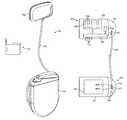
- FIGS. 1A and 1Billustrate components of a wireless cardiac stimulation system 101 , in accordance with an embodiment of the present invention.
- the WiCSTM systemcomprises a transmitter module 102 , a battery module 110 , a header or connector block 107 , a cable 120 , an external programmer 130 and one or more implantable receiver-stimulator units (not shown).
- Transmitter module 102comprises a transmitter enclosure 103 which houses one or more ultrasonic transducers 104 and electronics 105 for the generation and control of the ultrasound transmission.
- ultrasonic transducers 104 and electronics 105for the generation and control of the ultrasound transmission.
- using modem microelectronics methodssuch components may be made very small, thus causing a reduction in the overall size, thickness, and weight of the transmitter module 102 .
- multiple ultrasonic transducersare arranged as a transducer array 106 .
- Internal connections between the electronics 105 and the transducers 104 in the transducer array 106are not shown in detail in FIG. 1B .
- Hundreds of such transducers 104may be arranged in the array 106 . This poses special demands on establishing the electrical connections between the transducers and the electronics 105 that control the desired functioning of these transducers.
- different components of the transmitter modulecan be stacked on top of each other.
- the transducer array 106could be the bottom most layer (facing the heart), with the transmit electronics (transmit ASIC) organized on top of the transducer array, and the control electronics 105 (control ASIC) layered over the transmit ASIC.
- the sensing electrodes 140could be optimally distributed about the periphery of the outermost surface of the transmitter module.
- the transmitter module 102may be approximately 2.5 cm ⁇ 3.5 cm with a thickness of about 8 mm, allowing it to house a transducer array of approximately 2 cm ⁇ 3 cm. Other dimensions are possible, as will be known to those of skill in the art.
- Battery module 110comprises a battery enclosure 111 which houses a battery cell 112 used to power the transmitter module 102 .
- a header or connector block 113is incorporated onto the battery enclosure 111 .
- the battery module 110may likely be larger, thicker, and/or heavier than the transmitter module 102 , but such increased dimensions and weight are not an issue since slight movement or migration of the battery module 110 will not affect transmitter performance.
- One skilled in the artwould recognize that in an alternative embodiment (not shown), some or all of the electronics circuitry 105 could be located in battery module 110 . In such an embodiment, the transmitter module 102 could be even smaller than the embodiment where the electronics are present in the transmitter module 102 .
- the electrical connections between the modules 102 and 110could be established using appropriate connector and wiring that runs as part of the cable 120 .
- the battery module 110occupies a volume of about 35 cc. Using current battery technology, a battery module of such size would provide for approximately a 10 Amp-hour battery capacity. Using nominal transmission conditions to an R-S, this may provide approximately 3 years of service life for the device. It is contemplated that with advances in battery technology, the dimensions of the battery module 110 may be reduced without loss of battery capacity, or alternatively the battery module 110 may provide longer battery service life at approximately the same dimensions.
- a cable 120connects the two modules 102 and 110 and is preferably routed subcutaneously.
- cable 120comprises an electrical cable and allows battery cell 112 to power the transmitter module 102 .
- the cable 120could be thin, for increased patient comfort and ease of subcutaneous routing.
- one or both ends of the cable 120are terminated in connectors 121 to facilitate implantation of the enclosures.
- the connectors 121may be of similar design and construction to current implantable connector systems (such as IS-1, DS-1, LV-1) used in pacemakers and ICDs, it is important for safety reasons that connectors 121 used on the present wireless cardiac stimulation device 101 not be able to accept or connect to conventional pacemakers, ICDs, pacing lead wires, or defibrillator lead wires.
- the cable 120is permanently attached to the transmitter module 102 or alternatively permanently attached to battery module 110 , in which case only one end of the cable is terminated with connectors 121 .
- FIG. 1Cshows various components of the cable 120 .
- Cable 120contains wires to connect the terminals 1121 and 1122 of the battery cell 112 . Additionally it has wires connecting sensing electrodes 1131 and 1132 from the battery enclosure 110 to the transmitter assembly 102 .
- the cablealso has a shield 125 which may be braided, served or of similar construction that acts as the antenna and facilitates efficient communication between the devices and the external programmer 130 (shown in FIG. 1A ).
- the transmitter module 102 and the battery module 110are configured to be separately implantable.
- the transmitter module 102is implanted subcutaneously to be centered above an intercostal space, typically between the fourth and fifth ribs.
- the battery module 110is typically implanted below the transmitter module 102 at about 8 to 15 cm away from the transmitter module 102 , as illustrated in FIG. 2B . Procedural steps for implanting the transmitter module 102 and the battery module 110 are illustrated in FIG. 2A .
- the transmitter and battery modulesare implanted by first making a skin incision and then creating a subcutaneous tissue pocket in the region of an intercostal space overlying an acoustic window.
- the pocketis made to be slightly smaller than the transmitter module so that the transmitter module fits snugly in the space.
- This tissue pocketshould be centered between two ribs, such that when secured, the transmitter module is centered in the pocket in order to optimize the position of the transmitter module between two ribs such that the aperture of the transducer array would be centered above the intercostal space.
- the transmitter module and the aperture of the transducer arraymay be oversized for the space and extend slightly over the ribs. The transmitter is now placed in the pocket.
- the second incisionis made about 10 cm directly below the first incision and a second subcutaneous pocket is made to fit the battery module 110 . Then, using a tunneling instrument, such as a trocar, a channel is created between the two incisions and the cable is inserted into one of the incisions and exits through the second incision, leaving the cable routed between the two incisions. In the case where the cable is permanently attached to the transmitter module then the cable would be routed starting with the transmitter module pocket.
- the battery module 110is placed in the pocket created around the second incision.
- the cable 120is then connected to the battery module 110 .
- the transmitter module 102 and battery module 110are sutured to the fascia.
- the skin incisionsare closed using standard techniques.
- both modulesfastened in place and connected subcutaneously via the cable 120 .
- the present embodimentsdescribe the battery module 110 placed at a distance below the transmitter module 102 , it is possible to implant the battery module 110 in other locations, with the cable 120 routed between the two modules.
- the transmitter modulecould be located under the left breast and the battery module on the right side of the chest under the right breast with the cable 120 routed across and over the sternum.
- the transmitter module 102is subcutaneously implanted on the left chest wall overlying the heart.
- the transmitter module 102is sutured on the fascia over the intercostal muscle so that the transducer array is aligned between the 4th and 5th, or between the 5th and 6th ribs.
- Patientswill undergo specific testing, such as acoustic window assessment testing, to determine an optimal location for transmitter module 102 .
- the transmitter module 102is sized wider than the intercostal space over which it is sutured.
- the transmitter module 102may be obscured by ribs, or the transmitter may move with breathing, only an unobscured group of the transducers of the array 104 need be used to transmit acoustic energy.
- One techniqueis to determine such a group at the time of implantation or during clinical monitoring, with the help of an external programming module described below.
- Transducers 104 in the transducer array 106may be activated in a pre-determined pattern sequentially or in groups, for example in a raster scan pattern, and reception by one or more receiver-stimulators monitored to determine whether the activated transducers are obscured or not, such that unobscured transducers 104 may be chosen for transmission.
- a raster patternmay be employed during the operation of the transmitter module 102 to compensate for newly obscured transducers 104 as a result of a change in the spatial relationship of transmitter module 102 and the R-S. Details for optimizing energy transmission from the transmitter, and one such optimization method is to use only unobscured transducers of the array, can be found in co-pending U.S.
- the transmitter enclosure 103incorporates onto its exterior one or more features, such as suture points, to facilitate its alignment between two ribs, and by which it may be secured to the underlying fascia.
- the suture pointsmay be incorporated in the cable 120 or the connector 121 of the device.
- one advantageous aspect of the present embodimentsis that battery depletion does not necessitate surgical access to the transmitter module 102 for battery replacement followed by a repeat of the acoustic transmission testing, alignment, and fixation of the transmitter module 102 to the body. Instead, the separately implanted battery module 110 is accessed and the battery module 110 is replaced or explanted without disturbing or explanting the transmitter module 102 .
- the transmitter module 102 of the present embodimentshas a reduced mass and size which minimizes temporary or permanent migration of the transmitter module 102 due to patient movement or gravity.
- the wireless cardiac stimulation system 101utilizes radiofrequency communications to communicate with an external programmer unit 130 for initial setup and clinical monitoring.
- the radiofrequencyis in the Medical Implant Communications Service (MICS) band of approximately 402-405 MHz.
- a communication antennais used in conjunction with radio circuitry 132 (shown in FIG. 1B ).
- cable 120encases an antenna for the wireless cardiac stimulation system 101 , obviating the need for incorporating the antenna into the packaging of the transmitter module 102 or the battery module 110 . Incorporating the antenna in the cable 120 has the advantage of compensating for some of the losses that occur when transmitting and receiving RF energy through body tissue.
- a separate communication antennais used comprising a loop design, wherein the loop is designed to be as large as possible, located external to any metal housing, and located as shallow in the patient's body as possible.
- the antenna loopitself can be incorporated onto the outer-facing surface of the battery module 110 , which will likely be the larger of the two modules 102 and 110 (due to the generally larger size of the battery cell 112 ).
- the connections to the antennaare carried through the cable 120 routed between the two modules.
- the battery enclosure 111 and/or the transmitter enclosure 103comprise one or more electrodes 140 (shown in FIG. 1C ) for sensing electrogram signals. Electrodes 140 are incorporated onto the exterior surfaces of the enclosures. These electrodes are connected to amplifiers to process electrogram signals that can be used to provide the requisite sensing of electrical outputs from the receiver-stimulator in order to determine unobstructed transducers in the transducer array 106 , or in order to evaluate effectiveness of stimulation by sensing physiologic events. Signals registered by the sensing electrodes could also be advantageously used for monitoring the performance of the transmitter by observing whether the desired electrical output of the R-S is achieved.
Landscapes
- Health & Medical Sciences (AREA)
- Engineering & Computer Science (AREA)
- Biomedical Technology (AREA)
- Nuclear Medicine, Radiotherapy & Molecular Imaging (AREA)
- Radiology & Medical Imaging (AREA)
- Life Sciences & Earth Sciences (AREA)
- Animal Behavior & Ethology (AREA)
- General Health & Medical Sciences (AREA)
- Public Health (AREA)
- Veterinary Medicine (AREA)
- Electrotherapy Devices (AREA)
- Ultra Sonic Daignosis Equipment (AREA)
Abstract
Description
This application claims the benefit of the following provisional application: 61/016,869, filed on Dec. 27, 2007. The full disclosure of this prior filing is incorporated herein by reference.
The subject matter of this application is related to that of the following commonly owned patent application Ser. No. 10/315,023. The full disclosure of this prior filing is incorporated herein by reference but the benefit of the filing dates is not being claimed.
1. Field of the Invention
The field of the present invention relates generally to implanted devices for tissue stimulation, monitoring, and other therapeutic or diagnostic functions, and specifically to implantable devices for the stimulation of cardiac tissue, for example pacemakers or implantable cardioverter-defibrillators (ICDs). More specifically, it pertains to such devices utilizing wireless energy transfer, for example through ultrasonic means.
2. Description of the Background Art
Conventional cardiac pacemaker and defibrillator systems comprise Implantable Pulse Generators (IPGs) constructed with a single hermetically-sealed enclosure that contains the electronic control circuitry and battery components. The mass of an IPG for a conventional cardiac pacemaker is primarily dependent upon the volume and weight of the enclosed battery that powers the electronic control elements and stimulation energy of the IPG.
In order to have an IPG of acceptable size and weight for implantation in patients, the batteries on average do not last as long as the patients' lifetime. Cardiac pacemaker and defibrillator battery longevity ranges from about 3-9 years (Hauser et al., “Feasibility and Initial Results of an Internet-Based Pacemaker and ICD Pulse Generator and Lead Registry,” Pacing and Clinical Electrophysiology (PACE) 2001; 24:82-87). Therefore, many patients undergo multiple surgical procedures to replace the IPG.
For ease of insertion of pacing leads into the vasculature, the IPG is normally located subcutaneously in the pectoral region of the chest. This location is surgically accessible and near the typically used entry sites for the vascular leads. There is latitude with regards to the placement of the IPG enclosure. However, because it is connected to leads, the location and surgical process must consider lead insertion into a vascular access. Most often, the IPG is placed in a shallow subcutaneous pocket located in the upper left aspect of the chest, several centimeters below the clavicle. Venous access is then accomplished via the subclavian, cephalic, or axillary veins. This location generally allows the patient full range of movement with minimal discomfort. For example, see Hauser et al., 2001.
An ultrasound based Wireless Cardiac Stimulation (WiCS™) system has been disclosed in currently pending applications by the applicant (e.g., U.S. patent application Ser. No. 11/315,023). This system employs ultrasonic energy transfer from a subcutaneously implantable controller-transmitter device (C-T), which is directed towards one or more receiver-stimulator (R-S) devices implanted at desired sites in the heart, for example in the left ventricle. Ultrasonic transducers and circuitry in the R-S convert the transmitted ultrasonic energy into an electrical signal capable of stimulating the cardiac tissue. The WiCS™ system, C-T, and R-S are described in co-pending U.S. patent applications Nos. (Publication Number) 20060136004, 20060136005, 20070027508, 20070055184, 20070078490 and 20070060961 and Ser. No. 11/752,775, which are herein incorporated by reference in their entirety.
In the disclosed WiCS™ system, the C-T contains ultrasound elements as well as housing for the electronic control circuitry and battery. The C-T transmits ultrasound through the chest wall to the location of the R-S which may be placed in the left ventricle of the heart or any other heart location. In one preferred embodiment of the system, the transmitting aperture is located with a direct line of transmission between the C-T and the R-S—the direct line avoiding both bone and lung tissue to minimize transmission losses. Thus, it is desirable to place the transmitting aperture anteriorly over the rib cage of the left chest, and further desirable to align as much of the aperture of the transmitter as possible with the intercostal space between two ribs. It is still further desirable to tightly affix the transmitting aperture in the preferred location so that other factors, such as patient movement, do not disturb its position.
However, it can be observed that a significant portion of the general population, including potential recipients of the WiCS™ system, do not have significant thickness of muscle or fat tissue in the left anterior chest in the area of the 4th, 5th, and 6th ribs, which are preferred locations for such a device. Therefore, to improve patient comfort and to provide the largest usable aperture, it would be desirable to optimize the volume of devices implanted in this area, particularly by reducing the thickness of the device. To reduce the possible movement or dislodgement of the device, it would also be desirable to optimize its weight, particularly by reducing the mass of the device. The present embodiments address these challenges, as well as providing further advantages, as disclosed herein. Alternatively, other implant sites that have an unobstructed acoustic path between the C-T and R-S, for example, pericardial placement or subcostal placement, would be more practical if the C-T could remain undisturbed when replacing the battery.
Embodiments of the present invention are directed to wireless cardiac stimulation C-T devices comprising two separately implantable modules. The first module (transmitter module) houses a transmitter while the second houses a battery (battery module) for powering the system. The battery powers the transmitter via an implantable cable connecting the two modules. The control electronics could be housed in either module. The control electronics could include means for receiving instructions or programming from an external communications device and circuits for operating the transmitter and could be preferably located in the transmitter module.
The cable supplies power from the battery to the transmitter module. The cable can further comprise an antenna to facilitate communication between the implantable modules and an external programming module for initial setup or clinical monitoring of the system performance. In one embodiment, the antenna is incorporated into an outer-facing surface of the battery enclosure or in an alternative embodiment the antenna is incorporated into the cable, and the system comprises radio circuitry within the battery enclosure or the transmitter enclosure.
The system further comprises one or more sensing electrodes incorporated onto the surface of one or both the implanted modules or the cable. These electrodes could sense electrograms and the sensed information could be advantageously used for controlling the generation and transmission of acoustic energy from the transmitter module. The cable could further have connectors at both ends. In one embodiment, the cable is permanently attached to the transmitter module and the other end of the cable terminates in connectors that can be detachably attached to connectors on the battery module. This facilitates replacement of the battery module without having to disturb the implanted transmitter module.
In one embodiment, the enclosures comprise one or more features, such as localization or immobilization devices, e.g., suture points, incorporated onto their exteriors to facilitate their alignment. For example, the transmitter module may be localized over an intercostal space to align the transmitter with a receiver-stimulator in the heart and the battery module may be localized to the abdominal area to align its placement relative to the transmitter and connecting cable. The enclosures may be secured to underlying fascia, thereby stabilizing the modules relative to their respective chosen locations and preventing their dislodgement or movement due to patient movement.
Another aspect of the invention relates to a tissue stimulation system comprising an implantable transmitter module, a battery module and one or more receiver-stimulators wherein the transmitter and battery modules are connected by a cable, and the transmitter module comprises a transducer array. The transmitter module can additionally comprise various ASICs for generating, controlling and transmitting acoustic energy from the transmitter module. The circuits could be configured to be optimally distributed inside the transmitter module and one such configuration being where the ASICs are stacked on top of the transducer array, with the transducer array closest to the heart.
In yet another aspect of this invention, the tissue pocket that is created to house the transmitter module is slightly smaller than the transmitter module so that the transmitter module fits snugly in the space. Additionally, the transducer array is sized to be wider than the intercostal space such that at least a portion of the transducer array, the target tissue and the receiver stimulators implanted in the target tissue are always within the acoustic transmission path without being obscured by intervening tissues such as rib and lung.
Another aspect of this invention is methods and systems for optimizing energy transmission in implantable ultrasound transducer arrays comprising activating one or more ultrasound transducers to transmit acoustic energy towards an implanted receiver-stimulator, where the receiver-stimulator is configured to receive the acoustic energy and convert the received acoustic energy into electrical energy output. By monitoring the electrical energy output of the receiver-stimulator, it can be determined whether the ultrasound transducers of the controller-transmitter are obscured by intervening tissue. Additionally, this information about the unobscured transducers can be advantageously used for transmitting acoustic energy towards an implanted receiver-stimulator using the unobscured transducers, where the receiver-stimulator converts the received acoustic energy into electrical energy output to stimulate tissue at the location of the receiver-stimulator.
The invention has other advantages and features which will be more readily apparent from the following detailed description of the invention and the appended claims, when taken in conjunction with the accompanying drawings, in which:
In the following description, for purposes of explanation, numerous specific details are set forth in order to provide a thorough understanding of the invention. It will be apparent, however, to one skilled in the art that the invention can be practiced without these specific details.
An ultrasound based Wireless Cardiac Stimulation (WiCS™) system comprising two separate C-T enclosures is disclosed. The first enclosure houses one or more transducers and electronics to control the operation of the transducer(s). The second enclosure houses a battery. The battery powers the transducer(s) and electronics via an electrical cable connecting the enclosures.
In one embodiment, thetransmitter module 102 may be approximately 2.5 cm×3.5 cm with a thickness of about 8 mm, allowing it to house a transducer array of approximately 2 cm×3 cm. Other dimensions are possible, as will be known to those of skill in the art.
In one embodiment, thebattery module 110 occupies a volume of about 35 cc. Using current battery technology, a battery module of such size would provide for approximately a 10 Amp-hour battery capacity. Using nominal transmission conditions to an R-S, this may provide approximately 3 years of service life for the device. It is contemplated that with advances in battery technology, the dimensions of thebattery module 110 may be reduced without loss of battery capacity, or alternatively thebattery module 110 may provide longer battery service life at approximately the same dimensions.
Acable 120 connects the twomodules cable 120 comprises an electrical cable and allowsbattery cell 112 to power thetransmitter module 102. Thecable 120 could be thin, for increased patient comfort and ease of subcutaneous routing.
In one embodiment, one or both ends of thecable 120 are terminated inconnectors 121 to facilitate implantation of the enclosures. While theconnectors 121 may be of similar design and construction to current implantable connector systems (such as IS-1, DS-1, LV-1) used in pacemakers and ICDs, it is important for safety reasons thatconnectors 121 used on the present wirelesscardiac stimulation device 101 not be able to accept or connect to conventional pacemakers, ICDs, pacing lead wires, or defibrillator lead wires. In one embodiment, thecable 120 is permanently attached to thetransmitter module 102 or alternatively permanently attached tobattery module 110, in which case only one end of the cable is terminated withconnectors 121.
Thetransmitter module 102 and thebattery module 110 are configured to be separately implantable. In one embodiment, thetransmitter module 102 is implanted subcutaneously to be centered above an intercostal space, typically between the fourth and fifth ribs. Thebattery module 110 is typically implanted below thetransmitter module 102 at about 8 to 15 cm away from thetransmitter module 102, as illustrated inFIG. 2B . Procedural steps for implanting thetransmitter module 102 and thebattery module 110 are illustrated inFIG. 2A .
As shown inFIG. 2A , the transmitter and battery modules are implanted by first making a skin incision and then creating a subcutaneous tissue pocket in the region of an intercostal space overlying an acoustic window. The pocket is made to be slightly smaller than the transmitter module so that the transmitter module fits snugly in the space. This tissue pocket should be centered between two ribs, such that when secured, the transmitter module is centered in the pocket in order to optimize the position of the transmitter module between two ribs such that the aperture of the transducer array would be centered above the intercostal space. The transmitter module and the aperture of the transducer array may be oversized for the space and extend slightly over the ribs. The transmitter is now placed in the pocket. The second incision is made about 10 cm directly below the first incision and a second subcutaneous pocket is made to fit thebattery module 110. Then, using a tunneling instrument, such as a trocar, a channel is created between the two incisions and the cable is inserted into one of the incisions and exits through the second incision, leaving the cable routed between the two incisions. In the case where the cable is permanently attached to the transmitter module then the cable would be routed starting with the transmitter module pocket. Thebattery module 110 is placed in the pocket created around the second incision. Thecable 120 is then connected to thebattery module 110. Thetransmitter module 102 andbattery module 110 are sutured to the fascia. The skin incisions are closed using standard techniques. This leaves both modules fastened in place and connected subcutaneously via thecable 120. While the present embodiments describe thebattery module 110 placed at a distance below thetransmitter module 102, it is possible to implant thebattery module 110 in other locations, with thecable 120 routed between the two modules. For example, the transmitter module could be located under the left breast and the battery module on the right side of the chest under the right breast with thecable 120 routed across and over the sternum.
Unlike conventional cardiac pacemakers, it is an object of the present embodiments to achieve and maintain an efficient acoustic transmission path from thetransmitter module 102 to one or more receiver-stimulator devices (R-S) implanted inside the heart. In order to achieve such an acoustic path, thetransmitter module 102 is subcutaneously implanted on the left chest wall overlying the heart. In one embodiment, thetransmitter module 102 is sutured on the fascia over the intercostal muscle so that the transducer array is aligned between the 4th and 5th, or between the 5th and 6th ribs. Patients will undergo specific testing, such as acoustic window assessment testing, to determine an optimal location fortransmitter module 102.
In one embodiment comprising atransducer array 106, thetransmitter module 102 is sized wider than the intercostal space over which it is sutured. Optionally, since some of thetransducers 104 may be obscured by ribs, or the transmitter may move with breathing, only an unobscured group of the transducers of thearray 104 need be used to transmit acoustic energy. One technique is to determine such a group at the time of implantation or during clinical monitoring, with the help of an external programming module described below.Transducers 104 in thetransducer array 106 may be activated in a pre-determined pattern sequentially or in groups, for example in a raster scan pattern, and reception by one or more receiver-stimulators monitored to determine whether the activated transducers are obscured or not, such thatunobscured transducers 104 may be chosen for transmission. Optionally, such a raster pattern may be employed during the operation of thetransmitter module 102 to compensate for newly obscuredtransducers 104 as a result of a change in the spatial relationship oftransmitter module 102 and the R-S. Details for optimizing energy transmission from the transmitter, and one such optimization method is to use only unobscured transducers of the array, can be found in co-pending U.S. patent application Ser. No. 11/752,775 by applicant.
To optimize performance of the system, it is desirable to prevent or minimize movement of thetransmitter module 102. One way to achieve this is by suturing theenclosure 103 to the fascia covering the ribs and intercostal muscles, or to the fascia of the pectoralis muscle if it is present. In one embodiment, thetransmitter enclosure 103 incorporates onto its exterior one or more features, such as suture points, to facilitate its alignment between two ribs, and by which it may be secured to the underlying fascia. Alternatively, or additionally, the suture points may be incorporated in thecable 120 or theconnector 121 of the device.
Separation of thebattery cell 112 to a separate module rather than incorporating it into thetransmitter module 102 has numerous advantages. For example, one advantageous aspect of the present embodiments is that battery depletion does not necessitate surgical access to thetransmitter module 102 for battery replacement followed by a repeat of the acoustic transmission testing, alignment, and fixation of thetransmitter module 102 to the body. Instead, the separately implantedbattery module 110 is accessed and thebattery module 110 is replaced or explanted without disturbing or explanting thetransmitter module 102.
It is another advantageous aspect that thetransmitter module 102 of the present embodiments has a reduced mass and size which minimizes temporary or permanent migration of thetransmitter module 102 due to patient movement or gravity.
Furthermore, many patients tend to have little subcutaneous tissue, either muscular or adipose, in this region of the chest wall. Segregation of thebattery cell 112 from thetransmitter module 102, and the resulting reduction in the size and thickness of the transmitter implant, contributes to patient comfort and tolerance of the implantedtransmitter module 102 without sacrificing battery life.
Another important advantage gained from separately implanting thebattery module 110 and thetransmitter module 102 relates to communication between the devices or components of theWICS™ system 101; particularly between the implanted devices and an external programming module. In one embodiment, the wirelesscardiac stimulation system 101 utilizes radiofrequency communications to communicate with anexternal programmer unit 130 for initial setup and clinical monitoring. In one embodiment, the radiofrequency is in the Medical Implant Communications Service (MICS) band of approximately 402-405 MHz.
To facilitate low power transmission from the wirelesscardiac stimulation system 101 through the skin to theexternal programming module 130, a communication antenna is used in conjunction with radio circuitry132 (shown inFIG. 1B ). In one embodiment,cable 120 encases an antenna for the wirelesscardiac stimulation system 101, obviating the need for incorporating the antenna into the packaging of thetransmitter module 102 or thebattery module 110. Incorporating the antenna in thecable 120 has the advantage of compensating for some of the losses that occur when transmitting and receiving RF energy through body tissue. In another embodiment, a separate communication antenna is used comprising a loop design, wherein the loop is designed to be as large as possible, located external to any metal housing, and located as shallow in the patient's body as possible. Though theactual radio circuitry 132 may be located in eithermodule battery module 110, which will likely be the larger of the twomodules 102 and110 (due to the generally larger size of the battery cell112). In an embodiment wherein theradio circuitry 132 is located within thetransmitter module 102, the connections to the antenna are carried through thecable 120 routed between the two modules.
Optionally, thebattery enclosure 111 and/or thetransmitter enclosure 103 comprise one or more electrodes140 (shown inFIG. 1C ) for sensing electrogram signals.Electrodes 140 are incorporated onto the exterior surfaces of the enclosures. These electrodes are connected to amplifiers to process electrogram signals that can be used to provide the requisite sensing of electrical outputs from the receiver-stimulator in order to determine unobstructed transducers in thetransducer array 106, or in order to evaluate effectiveness of stimulation by sensing physiologic events. Signals registered by the sensing electrodes could also be advantageously used for monitoring the performance of the transmitter by observing whether the desired electrical output of the R-S is achieved.
Although the detailed description contains many specifics, these should not be construed as limiting the scope of the invention but merely as illustrating different examples and aspects of the invention. Particularly, while heart tissue is used as the target tissue to illustrate the invention, it should be noted that the target tissue could be other tissues which could benefit from the separation of the transmitter and battery modules. It should be appreciated that the scope of the invention includes other embodiments not discussed in detail above. Various other modifications, changes and variations which will be apparent to those skilled in the art may be made in the arrangement, operation and details of the method and apparatus of the present invention disclosed herein without departing from the spirit and scope of the invention as described here.
Claims (32)
1. A tissue stimulation system comprising:
an implantable battery module configured to house a battery to power a transmitter module;
wherein the transmitter module is separately implantable and comprises a transmitter enclosure and is configured for transmitting acoustic energy to one or more receiver-stimulator devices implantable in the tissue;
wherein the battery module and the transmitter module are connectable by an implantable cable wherein the cable conducts power from the battery to the transmitter module;
wherein the cable comprises an antenna, and the antenna is configured to facilitate a low power radiofrequency communication link between at least one of the implantable modules and an external programming module.
2. The system ofclaim 1 further comprising electronic circuitry for communication between an external device and the at least one implantable module.
3. The system ofclaim 2 , wherein the antenna is further configured to facilitate initial setup or clinical monitoring of the system performance.
4. The system ofclaim 2 , further comprising radio circuitry which is connected to the antenna to process a signal over the radiofrequency communication link.
5. The system ofclaim 1 , further comprising one or more sensing electrodes incorporated onto the surface of one or both of the implantable modules or the cable.
6. The system ofclaim 5 , wherein the cable further comprises one or more electrode connections.
7. The system ofclaim 1 , wherein the battery module can be explanted without explanting the transmitter module.
8. A tissue stimulation system comprising:
an implantable transmitter module, the transmitter module configured to transmit acoustic energy to one or more receiver-stimulators implantable in the tissue;
wherein the transmitter module is adapted to draw power from a battery housed in a separately implantable-battery module, the battery module and the transmitter module connectable by an implantable cable, wherein the cable conducts power from the battery to the transmitter module;
wherein the cable comprises an antenna, and the antenna is configured to facilitate a low power radiofrequency communication link between at least one of the implantable modules and an external programming module.
9. The system ofclaim 8 , further comprising electronic circuitry for communication between an external device and the at least one of the implantable module.
10. The system ofclaim 9 , wherein the antenna is further configured to facilitate initial setup or clinical monitoring of the system performance.
11. The system ofclaim 9 , further comprising a radio circuitry which is connected to the antenna to process a signal over the radiofrequency communication link.
12. The system ofclaim 8 , further comprising one or more sensing electrodes incorporated onto the surface of one or both of the implantable modules.
13. The system ofclaim 8 , wherein the cable comprises one or more electrode connections.
14. The system ofclaim 8 , wherein the transmitter module comprises one or more features incorporated onto its exterior to facilitate its alignment overlying an intercostal space and by which it may be secured to underlying fascia, thereby stabilizing the transmitter module relative to the intercostal space and preventing its dislodgement or movement due to patient movement.
15. The system ofclaim 14 , wherein the transmitter module is wider than the intercostal space, thereby allowing the transmitter module to be stably positioned relative to the intercostal space to optimize the use of an acoustic window.
16. The system ofclaim 8 , wherein one end of the cable is permanently attached to the transmitter module, and the other end is attached to the battery module using releasable connectors.
17. The system ofclaim 8 , wherein the transmitter module comprises a transducer array, wherein the transducer array is wider than an intercostal space in which the transmitter module is localized.
18. The system ofclaim 17 , wherein the transducer array targets the receiver-stimulator is through an acoustic window.
19. A method of optimizing energy utilization in ultrasound transducer arrays comprising:
activating one or more ultrasound transducers to transmit acoustic energy towards an implanted receiver-stimulator, wherein the receiver-stimulator is configured to receive the acoustic energy and convert the received acoustic energy into electrical energy output;
monitoring the electrical energy output; and
determining whether the ultrasound transducers are obscured by intervening tissue, based on the monitored output.
20. The method ofclaim 19 , further comprising activating those transducers that have been determined to be unobscured by intervening tissue and transmitting acoustic energy towards an implanted receiver-stimulator, wherein the receiver-stimulator converts the received acoustic energy into electrical energy output to stimulate tissue at the location of the receiver-stimulator.
21. The method ofclaim 19 , wherein the ultrasound transducer array is implantable and is located in a subcutaneous pocket above an intercostal space.
22. The method ofclaim 21 , wherein the transducer array is wider than the intercostal space.
23. A system for optimizing energy utilization in ultrasound transducer arrays comprising:
a controller-transmitter configured to activate one or more ultrasound transducers of a transducer array that transmit acoustic energy towards an implanted receiver-stimulator, wherein the receiver-stimulator is configured to receive the acoustic energy and convert the received acoustic energy into electrical energy output delivered to pacing electrodes at the location of the receiver-stimulator;
one or more sensing electrodes that are connected to the controller-transmitter and are configured to monitor the electrical energy output; and circuitry configured to identify the ultrasound transducers of the transducer array that are obscured by intervening tissue based on the monitored electrical energy output.
24. The system ofclaim 23 , further comprising activating the transducers in a pre-determined pattern.
25. The system ofclaim 23 , further comprising activating those transducers that have been identified to be unobscured by intervening tissue to target the receiver-stimulator with sufficient acoustic energy that the electrical energy output stimulates the tissue at the location of the receiver-stimulator.
26. The system ofclaim 23 , wherein the ultrasound transducer array is implantable in a subcutaneous pocket above an intercostal space.
27. The system ofclaim 26 , wherein the transducer array is wider than the intercostal space.
28. A tissue stimulation system comprising:
an implantable transmitter module;
a discrete, implantable battery module;
one or more implantable receiver-stimulators;
wherein the transmitter module comprises a transducer array comprising one or more ultrasound transducers and configured to transmit acoustic energy towards one or more of the receiver-stimulators;
the transmitter module is adapted to draw power from a battery housed in the implantable battery module; and the battery module and the transmitter module are connectable by an implantable cable;
wherein the cable comprises an antenna, and the antenna is configured to facilitate a low power radiofrequency communication link between at least one of the implantable modules and an external programming module.
29. A method of implanting a tissue stimulation system comprising:
implanting a transmitter module, wherein the transmitter module comprises a transducer array comprising one or more ultrasound transducers;
implanting a separate battery module, wherein the battery module comprises a battery;
connecting the transmitter module and the battery module using an implantable cable;
wherein the battery module supplies power to the transmitter module; and
the transmitter module is configured to transmit acoustic energy towards one or more implantable receiver-stimulators that are in contact with the tissue for stimulating the tissue;
wherein the cable comprises an antenna, and the antenna is configured to facilitate a low power radiofrequency communication link between at least one of the implantable modules and an external programming module.
30. A method of implanting a tissue stimulation system comprising:
implanting a separate battery module, wherein the battery module comprises a battery;
connecting the battery module to an existing implanted transmitter module using an implantable cable;
wherein the battery module supplies power to the transmitter module; and
the transmitter module is configured to transmit acoustic energy towards one or more implantable receiver-stimulators that are in contact with the tissue for stimulating the tissue;
wherein the cable comprises an antenna, and the antenna is configured to facilitate a low power radiofrequency communication link between at least one of the implantable modules and an external programming module.
31. The system as inclaim 1 ,8 , or28 , wherein the transmitter module is a controller-transmitter; and
wherein the antenna is configured to facilitate the communication link between the controller-transmitter and the external programming module.
32. The method as inclaim 29 , or30 , wherein the transmitter module is a controller-transmitter; and
wherein the antenna is configured to facilitate the communication link between the controller-transmitter and the external programming module.
Priority Applications (1)
| Application Number | Priority Date | Filing Date | Title |
|---|---|---|---|
| US12/340,395US7953493B2 (en) | 2007-12-27 | 2008-12-19 | Optimizing size of implantable medical devices by isolating the power source |
Applications Claiming Priority (2)
| Application Number | Priority Date | Filing Date | Title |
|---|---|---|---|
| US1686907P | 2007-12-27 | 2007-12-27 | |
| US12/340,395US7953493B2 (en) | 2007-12-27 | 2008-12-19 | Optimizing size of implantable medical devices by isolating the power source |
Publications (2)
| Publication Number | Publication Date |
|---|---|
| US20090264965A1 US20090264965A1 (en) | 2009-10-22 |
| US7953493B2true US7953493B2 (en) | 2011-05-31 |
Family
ID=40825080
Family Applications (1)
| Application Number | Title | Priority Date | Filing Date |
|---|---|---|---|
| US12/340,395Active2029-07-28US7953493B2 (en) | 2007-12-27 | 2008-12-19 | Optimizing size of implantable medical devices by isolating the power source |
Country Status (3)
| Country | Link |
|---|---|
| US (1) | US7953493B2 (en) |
| EP (1) | EP2234666B1 (en) |
| WO (1) | WO2009086405A2 (en) |
Cited By (93)
| Publication number | Priority date | Publication date | Assignee | Title |
|---|---|---|---|---|
| US8649875B2 (en) | 2005-09-10 | 2014-02-11 | Artann Laboratories Inc. | Systems for remote generation of electrical signal in tissue based on time-reversal acoustics |
| US9492671B2 (en) | 2014-05-06 | 2016-11-15 | Medtronic, Inc. | Acoustically triggered therapy delivery |
| US9511233B2 (en) | 2013-11-21 | 2016-12-06 | Medtronic, Inc. | Systems and methods for leadless cardiac resynchronization therapy |
| US9526909B2 (en) | 2014-08-28 | 2016-12-27 | Cardiac Pacemakers, Inc. | Medical device with triggered blanking period |
| US9544068B2 (en) | 2013-05-13 | 2017-01-10 | The Board Of Trustees Of The Leland Stanford Junior University | Hybrid communication system for implantable devices and ultra-low power sensors |
| US9592391B2 (en) | 2014-01-10 | 2017-03-14 | Cardiac Pacemakers, Inc. | Systems and methods for detecting cardiac arrhythmias |
| US9669230B2 (en) | 2015-02-06 | 2017-06-06 | Cardiac Pacemakers, Inc. | Systems and methods for treating cardiac arrhythmias |
| US9669224B2 (en) | 2014-05-06 | 2017-06-06 | Medtronic, Inc. | Triggered pacing system |
| US9700731B2 (en) | 2014-08-15 | 2017-07-11 | Axonics Modulation Technologies, Inc. | Antenna and methods of use for an implantable nerve stimulator |
| US9731138B1 (en) | 2016-02-17 | 2017-08-15 | Medtronic, Inc. | System and method for cardiac pacing |
| US9802055B2 (en) | 2016-04-04 | 2017-10-31 | Medtronic, Inc. | Ultrasound powered pulse delivery device |
| US9853743B2 (en) | 2015-08-20 | 2017-12-26 | Cardiac Pacemakers, Inc. | Systems and methods for communication between medical devices |
| US9956414B2 (en) | 2015-08-27 | 2018-05-01 | Cardiac Pacemakers, Inc. | Temporal configuration of a motion sensor in an implantable medical device |
| US9968787B2 (en) | 2015-08-27 | 2018-05-15 | Cardiac Pacemakers, Inc. | Spatial configuration of a motion sensor in an implantable medical device |
| US10029107B1 (en) | 2017-01-26 | 2018-07-24 | Cardiac Pacemakers, Inc. | Leadless device with overmolded components |
| US10050700B2 (en) | 2015-03-18 | 2018-08-14 | Cardiac Pacemakers, Inc. | Communications in a medical device system with temporal optimization |
| US10046167B2 (en) | 2015-02-09 | 2018-08-14 | Cardiac Pacemakers, Inc. | Implantable medical device with radiopaque ID tag |
| US10052492B2 (en) | 2015-05-06 | 2018-08-21 | Verily Life Sciences Llc | Replaceable battery for implantable devices |
| US10065041B2 (en) | 2015-10-08 | 2018-09-04 | Cardiac Pacemakers, Inc. | Devices and methods for adjusting pacing rates in an implantable medical device |
| US10092760B2 (en) | 2015-09-11 | 2018-10-09 | Cardiac Pacemakers, Inc. | Arrhythmia detection and confirmation |
| US10118054B2 (en) | 2016-07-07 | 2018-11-06 | The Regents Of The University Of California | Implants using ultrasonic backscatter for sensing physiological conditions |
| US10137305B2 (en) | 2015-08-28 | 2018-11-27 | Cardiac Pacemakers, Inc. | Systems and methods for behaviorally responsive signal detection and therapy delivery |
| US10159842B2 (en) | 2015-08-28 | 2018-12-25 | Cardiac Pacemakers, Inc. | System and method for detecting tamponade |
| US10183170B2 (en) | 2015-12-17 | 2019-01-22 | Cardiac Pacemakers, Inc. | Conducted communication in a medical device system |
| US10213610B2 (en) | 2015-03-18 | 2019-02-26 | Cardiac Pacemakers, Inc. | Communications in a medical device system with link quality assessment |
| US10220213B2 (en) | 2015-02-06 | 2019-03-05 | Cardiac Pacemakers, Inc. | Systems and methods for safe delivery of electrical stimulation therapy |
| US10226631B2 (en) | 2015-08-28 | 2019-03-12 | Cardiac Pacemakers, Inc. | Systems and methods for infarct detection |
| US10328272B2 (en) | 2016-05-10 | 2019-06-25 | Cardiac Pacemakers, Inc. | Retrievability for implantable medical devices |
| US10350423B2 (en) | 2016-02-04 | 2019-07-16 | Cardiac Pacemakers, Inc. | Delivery system with force sensor for leadless cardiac device |
| US10357159B2 (en) | 2015-08-20 | 2019-07-23 | Cardiac Pacemakers, Inc | Systems and methods for communication between medical devices |
| US10391319B2 (en) | 2016-08-19 | 2019-08-27 | Cardiac Pacemakers, Inc. | Trans septal implantable medical device |
| US10413733B2 (en) | 2016-10-27 | 2019-09-17 | Cardiac Pacemakers, Inc. | Implantable medical device with gyroscope |
| US10426962B2 (en) | 2016-07-07 | 2019-10-01 | Cardiac Pacemakers, Inc. | Leadless pacemaker using pressure measurements for pacing capture verification |
| US10434317B2 (en) | 2016-10-31 | 2019-10-08 | Cardiac Pacemakers, Inc. | Systems and methods for activity level pacing |
| US10434314B2 (en) | 2016-10-27 | 2019-10-08 | Cardiac Pacemakers, Inc. | Use of a separate device in managing the pace pulse energy of a cardiac pacemaker |
| US10463305B2 (en) | 2016-10-27 | 2019-11-05 | Cardiac Pacemakers, Inc. | Multi-device cardiac resynchronization therapy with timing enhancements |
| US20190336776A1 (en)* | 2006-06-20 | 2019-11-07 | Ebr Systems, Inc. | Systems and methods for implantable leadless tissue stimulation |
| US10512784B2 (en) | 2016-06-27 | 2019-12-24 | Cardiac Pacemakers, Inc. | Cardiac therapy system using subcutaneously sensed P-waves for resynchronization pacing management |
| US10561330B2 (en) | 2016-10-27 | 2020-02-18 | Cardiac Pacemakers, Inc. | Implantable medical device having a sense channel with performance adjustment |
| US10583303B2 (en) | 2016-01-19 | 2020-03-10 | Cardiac Pacemakers, Inc. | Devices and methods for wirelessly recharging a rechargeable battery of an implantable medical device |
| US10583301B2 (en) | 2016-11-08 | 2020-03-10 | Cardiac Pacemakers, Inc. | Implantable medical device for atrial deployment |
| US10596383B2 (en) | 2018-04-03 | 2020-03-24 | Medtronic, Inc. | Feature based sensing for leadless pacing therapy |
| US10617874B2 (en) | 2016-10-31 | 2020-04-14 | Cardiac Pacemakers, Inc. | Systems and methods for activity level pacing |
| US10632313B2 (en) | 2016-11-09 | 2020-04-28 | Cardiac Pacemakers, Inc. | Systems, devices, and methods for setting cardiac pacing pulse parameters for a cardiac pacing device |
| US10639486B2 (en) | 2016-11-21 | 2020-05-05 | Cardiac Pacemakers, Inc. | Implantable medical device with recharge coil |
| US10668294B2 (en) | 2016-05-10 | 2020-06-02 | Cardiac Pacemakers, Inc. | Leadless cardiac pacemaker configured for over the wire delivery |
| US10675476B2 (en) | 2016-12-22 | 2020-06-09 | Cardiac Pacemakers, Inc. | Internal thoracic vein placement of a transmitter electrode for leadless stimulation of the heart |
| US10688304B2 (en) | 2016-07-20 | 2020-06-23 | Cardiac Pacemakers, Inc. | Method and system for utilizing an atrial contraction timing fiducial in a leadless cardiac pacemaker system |
| US10722720B2 (en) | 2014-01-10 | 2020-07-28 | Cardiac Pacemakers, Inc. | Methods and systems for improved communication between medical devices |
| US10737102B2 (en) | 2017-01-26 | 2020-08-11 | Cardiac Pacemakers, Inc. | Leadless implantable device with detachable fixation |
| US10758737B2 (en) | 2016-09-21 | 2020-09-01 | Cardiac Pacemakers, Inc. | Using sensor data from an intracardially implanted medical device to influence operation of an extracardially implantable cardioverter |
| US10758724B2 (en) | 2016-10-27 | 2020-09-01 | Cardiac Pacemakers, Inc. | Implantable medical device delivery system with integrated sensor |
| US10765871B2 (en) | 2016-10-27 | 2020-09-08 | Cardiac Pacemakers, Inc. | Implantable medical device with pressure sensor |
| US10780278B2 (en) | 2016-08-24 | 2020-09-22 | Cardiac Pacemakers, Inc. | Integrated multi-device cardiac resynchronization therapy using P-wave to pace timing |
| US10821288B2 (en) | 2017-04-03 | 2020-11-03 | Cardiac Pacemakers, Inc. | Cardiac pacemaker with pacing pulse energy adjustment based on sensed heart rate |
| US10835753B2 (en) | 2017-01-26 | 2020-11-17 | Cardiac Pacemakers, Inc. | Intra-body device communication with redundant message transmission |
| US10870008B2 (en) | 2016-08-24 | 2020-12-22 | Cardiac Pacemakers, Inc. | Cardiac resynchronization using fusion promotion for timing management |
| US10874861B2 (en) | 2018-01-04 | 2020-12-29 | Cardiac Pacemakers, Inc. | Dual chamber pacing without beat-to-beat communication |
| US10881869B2 (en) | 2016-11-21 | 2021-01-05 | Cardiac Pacemakers, Inc. | Wireless re-charge of an implantable medical device |
| US10881863B2 (en) | 2016-11-21 | 2021-01-05 | Cardiac Pacemakers, Inc. | Leadless cardiac pacemaker with multimode communication |
| US10894163B2 (en) | 2016-11-21 | 2021-01-19 | Cardiac Pacemakers, Inc. | LCP based predictive timing for cardiac resynchronization |
| US10905872B2 (en) | 2017-04-03 | 2021-02-02 | Cardiac Pacemakers, Inc. | Implantable medical device with a movable electrode biased toward an extended position |
| US10905889B2 (en) | 2016-09-21 | 2021-02-02 | Cardiac Pacemakers, Inc. | Leadless stimulation device with a housing that houses internal components of the leadless stimulation device and functions as the battery case and a terminal of an internal battery |
| US10905886B2 (en) | 2015-12-28 | 2021-02-02 | Cardiac Pacemakers, Inc. | Implantable medical device for deployment across the atrioventricular septum |
| US10918875B2 (en) | 2017-08-18 | 2021-02-16 | Cardiac Pacemakers, Inc. | Implantable medical device with a flux concentrator and a receiving coil disposed about the flux concentrator |
| US10994145B2 (en) | 2016-09-21 | 2021-05-04 | Cardiac Pacemakers, Inc. | Implantable cardiac monitor |
| US11052258B2 (en) | 2017-12-01 | 2021-07-06 | Cardiac Pacemakers, Inc. | Methods and systems for detecting atrial contraction timing fiducials within a search window from a ventricularly implanted leadless cardiac pacemaker |
| US11058880B2 (en) | 2018-03-23 | 2021-07-13 | Medtronic, Inc. | VFA cardiac therapy for tachycardia |
| US11065459B2 (en) | 2017-08-18 | 2021-07-20 | Cardiac Pacemakers, Inc. | Implantable medical device with pressure sensor |
| US11071870B2 (en) | 2017-12-01 | 2021-07-27 | Cardiac Pacemakers, Inc. | Methods and systems for detecting atrial contraction timing fiducials and determining a cardiac interval from a ventricularly implanted leadless cardiac pacemaker |
| US11116988B2 (en) | 2016-03-31 | 2021-09-14 | Cardiac Pacemakers, Inc. | Implantable medical device with rechargeable battery |
| US11147979B2 (en) | 2016-11-21 | 2021-10-19 | Cardiac Pacemakers, Inc. | Implantable medical device with a magnetically permeable housing and an inductive coil disposed about the housing |
| US11185703B2 (en) | 2017-11-07 | 2021-11-30 | Cardiac Pacemakers, Inc. | Leadless cardiac pacemaker for bundle of his pacing |
| US11207532B2 (en) | 2017-01-04 | 2021-12-28 | Cardiac Pacemakers, Inc. | Dynamic sensing updates using postural input in a multiple device cardiac rhythm management system |
| US11207527B2 (en) | 2016-07-06 | 2021-12-28 | Cardiac Pacemakers, Inc. | Method and system for determining an atrial contraction timing fiducial in a leadless cardiac pacemaker system |
| US11213676B2 (en) | 2019-04-01 | 2022-01-04 | Medtronic, Inc. | Delivery systems for VfA cardiac therapy |
| US11235163B2 (en) | 2017-09-20 | 2022-02-01 | Cardiac Pacemakers, Inc. | Implantable medical device with multiple modes of operation |
| US11235161B2 (en) | 2018-09-26 | 2022-02-01 | Medtronic, Inc. | Capture in ventricle-from-atrium cardiac therapy |
| US11235159B2 (en) | 2018-03-23 | 2022-02-01 | Medtronic, Inc. | VFA cardiac resynchronization therapy |
| US11260216B2 (en) | 2017-12-01 | 2022-03-01 | Cardiac Pacemakers, Inc. | Methods and systems for detecting atrial contraction timing fiducials during ventricular filling from a ventricularly implanted leadless cardiac pacemaker |
| US11285326B2 (en) | 2015-03-04 | 2022-03-29 | Cardiac Pacemakers, Inc. | Systems and methods for treating cardiac arrhythmias |
| US11305127B2 (en) | 2019-08-26 | 2022-04-19 | Medtronic Inc. | VfA delivery and implant region detection |
| US11400296B2 (en) | 2018-03-23 | 2022-08-02 | Medtronic, Inc. | AV synchronous VfA cardiac therapy |
| US11529523B2 (en) | 2018-01-04 | 2022-12-20 | Cardiac Pacemakers, Inc. | Handheld bridge device for providing a communication bridge between an implanted medical device and a smartphone |
| US11679265B2 (en) | 2019-02-14 | 2023-06-20 | Medtronic, Inc. | Lead-in-lead systems and methods for cardiac therapy |
| US11697025B2 (en) | 2019-03-29 | 2023-07-11 | Medtronic, Inc. | Cardiac conduction system capture |
| US11712188B2 (en) | 2019-05-07 | 2023-08-01 | Medtronic, Inc. | Posterior left bundle branch engagement |
| US11813463B2 (en) | 2017-12-01 | 2023-11-14 | Cardiac Pacemakers, Inc. | Leadless cardiac pacemaker with reversionary behavior |
| US11813466B2 (en) | 2020-01-27 | 2023-11-14 | Medtronic, Inc. | Atrioventricular nodal stimulation |
| US11813464B2 (en) | 2020-07-31 | 2023-11-14 | Medtronic, Inc. | Cardiac conduction system evaluation |
| US11911168B2 (en) | 2020-04-03 | 2024-02-27 | Medtronic, Inc. | Cardiac conduction system therapy benefit determination |
| US11951313B2 (en) | 2018-11-17 | 2024-04-09 | Medtronic, Inc. | VFA delivery systems and methods |
| US12296177B2 (en) | 2018-12-21 | 2025-05-13 | Medtronic, Inc. | Delivery systems and methods for left ventricular pacing |
Families Citing this family (3)
| Publication number | Priority date | Publication date | Assignee | Title |
|---|---|---|---|---|
| US20170281936A1 (en)* | 2016-04-01 | 2017-10-05 | Boston Scientific Neuromodulation Corporation | Convertible Implantable Stimulator |
| HUE066899T2 (en) | 2018-08-31 | 2024-09-28 | Hoffmann La Roche | Modular implantable medical device |
| WO2020159886A1 (en)* | 2019-01-28 | 2020-08-06 | Steven Kim | Devices, systems, and methods for cardiac resynchronization therapy |
Citations (98)
| Publication number | Priority date | Publication date | Assignee | Title |
|---|---|---|---|---|
| US3659615A (en) | 1970-06-08 | 1972-05-02 | Carl C Enger | Encapsulated non-permeable piezoelectric powered pacesetter |
| US3693627A (en) | 1970-09-14 | 1972-09-26 | American Optical Corp | Stimulator for treatment of tachycardia with a burst of stimuli having a continuously variable rate |
| US3698398A (en) | 1970-11-06 | 1972-10-17 | American Optical Corp | Rate-scanning pacer for treatment of tachycardia |
| US3735756A (en) | 1971-06-23 | 1973-05-29 | Medco Products Co Inc | Duplex ultrasound generator and combined electrical muscle stimulator |
| US3832994A (en) | 1972-04-21 | 1974-09-03 | Mediscience Corp | Cardiac monitor |
| US3857382A (en) | 1972-10-27 | 1974-12-31 | Sinai Hospital Of Detroit | Piezoelectric heart assist apparatus |
| US3939844A (en) | 1973-10-18 | 1976-02-24 | Michel Pequignot | Method and apparatus for stimulating a heart to eliminate rhythmic abnormalities, especially tachycardias |
| US3942534A (en) | 1973-11-21 | 1976-03-09 | Kenneth Roy Allen | Device for terminating tachycardia |
| US4181133A (en) | 1978-05-22 | 1980-01-01 | Arco Medical Products Company | Programmable tachycardia pacer |
| US4256115A (en) | 1976-12-20 | 1981-03-17 | American Technology, Inc. | Leadless cardiac pacer |
| US4265228A (en) | 1978-09-14 | 1981-05-05 | Zoll Paul M | Mechanical pacemaker |
| US4280502A (en) | 1979-08-08 | 1981-07-28 | Intermedics, Inc. | Tachycardia arrester |
| US4561442A (en) | 1983-10-17 | 1985-12-31 | Cordis Corporation | Implantable cardiac pacer with discontinuous microprocessor programmable antitachycardia mechanisms and patient data telemetry |
| US4577633A (en) | 1984-03-28 | 1986-03-25 | Medtronic, Inc. | Rate scanning demand pacemaker and method for treatment of tachycardia |
| US4651716A (en) | 1982-12-03 | 1987-03-24 | Canadian Patents And Development Limited | Method and device for enhancement of cardiac contractility |
| US4690144A (en) | 1982-04-02 | 1987-09-01 | Medtronic, Inc. | Wireless transcutaneous electrical tissue stimulator |
| US4830006A (en) | 1986-06-17 | 1989-05-16 | Intermedics, Inc. | Implantable cardiac stimulator for detection and treatment of ventricular arrhythmias |
| US5018523A (en) | 1990-04-23 | 1991-05-28 | Cardiac Pacemakers, Inc. | Apparatus for common mode stimulation with bipolar sensing |
| US5063928A (en) | 1990-07-05 | 1991-11-12 | Telectronics Pacing Systems, Inc. | Apparatus and method for detecting and treating cardiac tachyarrhythmias |
| US5103129A (en) | 1990-07-26 | 1992-04-07 | Acoustic Imaging Technologies Corporation | Fixed origin biplane ultrasonic transducer |
| US5113859A (en) | 1988-09-19 | 1992-05-19 | Medtronic, Inc. | Acoustic body bus medical device communication system |
| US5165403A (en) | 1991-02-26 | 1992-11-24 | Medtronic, Inc. | Difibrillation lead system and method of use |
| US5170784A (en) | 1990-11-27 | 1992-12-15 | Ceon Ramon | Leadless magnetic cardiac pacemaker |
| US5174289A (en) | 1990-09-07 | 1992-12-29 | Cohen Fred M | Pacing systems and methods for control of the ventricular activation sequence |
| US5193539A (en) | 1991-12-18 | 1993-03-16 | Alfred E. Mann Foundation For Scientific Research | Implantable microstimulator |
| US5292338A (en) | 1992-07-30 | 1994-03-08 | Medtronic, Inc. | Atrial defibrillator employing transvenous and subcutaneous electrodes and method of use |
| US5377166A (en) | 1994-01-25 | 1994-12-27 | Martin Marietta Corporation | Polyhedral directional transducer array |
| DE4330680A1 (en) | 1993-09-10 | 1995-03-16 | Michael Dr Zwicker | Device for electrical stimulation of cells within a living human or animal |
| US5405367A (en) | 1991-12-18 | 1995-04-11 | Alfred E. Mann Foundation For Scientific Research | Structure and method of manufacture of an implantable microstimulator |
| US5411535A (en) | 1992-03-03 | 1995-05-02 | Terumo Kabushiki Kaisha | Cardiac pacemaker using wireless transmission |
| US5433731A (en) | 1993-03-29 | 1995-07-18 | Pacesetter Ab | Mechanical defibrillator and method for defibrillating a heart |
| US5674251A (en) | 1994-04-21 | 1997-10-07 | Medtronic, Inc. | Method and apparatus for treatment of atrial fibrillation |
| US5749909A (en) | 1996-11-07 | 1998-05-12 | Sulzer Intermedics Inc. | Transcutaneous energy coupling using piezoelectric device |
| US5751539A (en) | 1996-04-30 | 1998-05-12 | Maxwell Laboratories, Inc. | EMI filter for human implantable heart defibrillators and pacemakers |
| US5757104A (en) | 1994-10-10 | 1998-05-26 | Endress + Hauser Gmbh + Co. | Method of operating an ultransonic piezoelectric transducer and circuit arrangement for performing the method |
| US5766227A (en) | 1997-03-04 | 1998-06-16 | Nappholz; Tibor A. | EMI detection in an implantable pacemaker and the like |
| US5800464A (en) | 1996-10-03 | 1998-09-01 | Medtronic, Inc. | System for providing hyperpolarization of cardiac to enhance cardiac function |
| US5814089A (en) | 1996-12-18 | 1998-09-29 | Medtronic, Inc. | Leadless multisite implantable stimulus and diagnostic system |
| US5817130A (en) | 1996-05-03 | 1998-10-06 | Sulzer Intermedics Inc. | Implantable cardiac cardioverter/defibrillator with EMI suppression filter with independent ground connection |
| US5844349A (en) | 1997-02-11 | 1998-12-01 | Tetrad Corporation | Composite autoclavable ultrasonic transducers and methods of making |
| US5871506A (en) | 1996-08-19 | 1999-02-16 | Mower; Morton M. | Augmentation of electrical conduction and contractility by biphasic cardiac pacing |
| US5935158A (en) | 1996-08-23 | 1999-08-10 | Pacesetter Ab | Electrode lead and device for tissue stimulation and/or detection of tissue response |
| US5978204A (en) | 1995-11-27 | 1999-11-02 | Maxwell Energy Products, Inc. | Capacitor with dual element electrode plates |
| WO1999061058A1 (en) | 1998-05-23 | 1999-12-02 | Quadrant Healthcare (Uk) Limited | Method of altering heartbeat |
| US5998910A (en) | 1997-01-28 | 1999-12-07 | The Penn State Research Foundation | Relaxor ferroelectric single crystals for ultrasound transducers |
| US6037704A (en) | 1997-10-08 | 2000-03-14 | The Aerospace Corporation | Ultrasonic power communication system |
| US6070101A (en) | 1998-04-28 | 2000-05-30 | Medtronic, Inc. | Multiple channel, sequential, cardiac pacing systems |
| US6078837A (en) | 1999-01-27 | 2000-06-20 | Medtronic, Inc. | Method and apparatus for treatment of fibrillation |
| US6110098A (en) | 1996-12-18 | 2000-08-29 | Medtronic, Inc. | System and method of mechanical treatment of cardiac fibrillation |
| US6141588A (en) | 1998-07-24 | 2000-10-31 | Intermedics Inc. | Cardiac simulation system having multiple stimulators for anti-arrhythmia therapy |
| US6208894B1 (en) | 1997-02-26 | 2001-03-27 | Alfred E. Mann Foundation For Scientific Research And Advanced Bionics | System of implantable devices for monitoring and/or affecting body parameters |
| US6223079B1 (en) | 1997-12-15 | 2001-04-24 | Medtronic, Inc | Bi-ventricular pacing method |
| US6233484B1 (en) | 1996-09-16 | 2001-05-15 | Impulse Dynamics N.V. | Apparatus and method for controlling the contractility of muscles |
| US6366816B1 (en) | 1998-12-23 | 2002-04-02 | Fabio Paolo Marchesi | Electronic stimulation equipment with wireless satellite units |
| US6424234B1 (en) | 1998-09-18 | 2002-07-23 | Greatbatch-Sierra, Inc. | Electromagnetic interference (emi) filter and process for providing electromagnetic compatibility of an electronic device while in the presence of an electromagnetic emitter operating at the same frequency |
| US6439236B1 (en) | 1999-10-25 | 2002-08-27 | The Board Of Regents Of The University Of Nebraska | Methods for inducing atrial and ventricular rhythms using ultrasound and microbubbles |
| US6445953B1 (en) | 2001-01-16 | 2002-09-03 | Kenergy, Inc. | Wireless cardiac pacing system with vascular electrode-stents |
| US6534895B2 (en) | 2000-05-01 | 2003-03-18 | Murata Manufacturing Co., Ltd. | Surface acoustic wave device, shear bulk wave transducer, and longitudinal bulk wave transducer |
| USRE38119E1 (en) | 1989-01-23 | 2003-05-20 | Mirowski Family Ventures, LLC | Method and apparatus for treating hemodynamic disfunction |
| US20030119153A1 (en) | 1998-03-18 | 2003-06-26 | Ajinomoto Co. Inc. | L-glutamic acid-producing bacterium and method for producing L-glutamic acid |
| WO2003070323A1 (en) | 2002-02-21 | 2003-08-28 | Technion Research & Development Foundation Ltd. | Ultrasound cardiac stimulator |
| US6628989B1 (en) | 2000-10-16 | 2003-09-30 | Remon Medical Technologies, Ltd. | Acoustic switch and apparatus and methods for using acoustic switches within a body |
| US6645145B1 (en) | 1998-11-19 | 2003-11-11 | Siemens Medical Solutions Usa, Inc. | Diagnostic medical ultrasound systems and transducers utilizing micro-mechanical components |
| US6647292B1 (en) | 2000-09-18 | 2003-11-11 | Cameron Health | Unitary subcutaneous only implantable cardioverter-defibrillator and optional pacer |
| US6654638B1 (en) | 2000-04-06 | 2003-11-25 | Cardiac Pacemakers, Inc. | Ultrasonically activated electrodes |
| US6671547B2 (en) | 2001-06-13 | 2003-12-30 | Koninklijke Philips Electronics N.V. | Adaptive analysis method for an electrotherapy device and apparatus |
| US20040015104A1 (en) | 2002-02-11 | 2004-01-22 | Gold-T Tech, Inc. | Method for preventing thrombus formation |
| US6707230B2 (en) | 2001-05-29 | 2004-03-16 | University Of North Carolina At Charlotte | Closed loop control systems employing relaxor ferroelectric actuators |
| US6721597B1 (en) | 2000-09-18 | 2004-04-13 | Cameron Health, Inc. | Subcutaneous only implantable cardioverter defibrillator and optional pacer |
| US20040106963A1 (en)* | 2001-11-07 | 2004-06-03 | Quallion Llc | Implantable medical power module |
| US6754531B1 (en) | 2001-10-19 | 2004-06-22 | Pacesetter, Inc. | Anti-tachycardia pacing methods and devices |
| US6754528B2 (en) | 2001-11-21 | 2004-06-22 | Cameraon Health, Inc. | Apparatus and method of arrhythmia detection in a subcutaneous implantable cardioverter/defibrillator |
| US6764446B2 (en) | 2000-10-16 | 2004-07-20 | Remon Medical Technologies Ltd | Implantable pressure sensors and methods for making and using them |
| US20040172083A1 (en) | 2000-10-16 | 2004-09-02 | Remon Medical Technologies Ltd. | Acoustically powered implantable stimulating device |
| US6788974B2 (en) | 2000-09-18 | 2004-09-07 | Cameron Health, Inc. | Radian curve shaped implantable cardioverter-defibrillator canister |
| US6798716B1 (en) | 2003-06-19 | 2004-09-28 | Bc Systems, Inc. | System and method for wireless electrical power transmission |
| US20040204744A1 (en) | 2003-04-14 | 2004-10-14 | Remon Medicaltechnologies Ltd. | Apparatus and methods using acoustic telemetry for intrabody communications |
| US20040243192A1 (en) | 2003-06-02 | 2004-12-02 | Hepp Dennis G. | Physiologic stimulator tuning apparatus and method |
| US6834204B2 (en) | 2001-11-05 | 2004-12-21 | Cameron Health, Inc. | Method and apparatus for inducing defibrillation in a patient using a T-shock waveform |
| US20040260214A1 (en) | 2003-06-17 | 2004-12-23 | Ebr Systems, Inc. | Methods and systems for vibrational treatment of cardiac arrhythmias |
| US6856835B2 (en) | 2000-09-18 | 2005-02-15 | Cameron Health, Inc. | Biphasic waveform for anti-tachycardia pacing for a subcutaneous implantable cardioverter-defibrillator |
| US20050192639A1 (en)* | 2000-09-18 | 2005-09-01 | Cameron Health, Inc. | Flexible subcutaneous implantable cardioverter-defibrillator |
| US6983185B2 (en) | 1998-07-22 | 2006-01-03 | Cardiac Pacemakers, Inc. | Lead with terminal connector assembly |
| US7010350B2 (en) | 2001-03-21 | 2006-03-07 | Kralik Michael R | Temporary biventricular pacing of heart after heart surgery |
| US7024248B2 (en) | 2000-10-16 | 2006-04-04 | Remon Medical Technologies Ltd | Systems and methods for communicating with implantable devices |
| US20060136005A1 (en) | 2004-12-21 | 2006-06-22 | Ebr Systems, Inc. | Implantable transducer devices |
| US20060184204A1 (en) | 2005-02-11 | 2006-08-17 | Advanced Bionics Corporation | Implantable microstimulator having a separate battery unit and methods of use thereof |
| US20070027508A1 (en) | 2005-08-01 | 2007-02-01 | Ebr Systems, Inc. | Efficiently delivering acoustic stimulation energy to tissue |
| US20070055184A1 (en) | 2005-08-31 | 2007-03-08 | Ebr Systems, Inc. | Methods and systems for heart failure prevention and treatments using ultrasound and leadless implantable devices |
| US20070060961A1 (en) | 2005-09-12 | 2007-03-15 | Ebr Systems, Inc. | Methods and apparatus for determining cardiac stimulation sites using hemodynamic data |
| US7200437B1 (en) | 2004-10-13 | 2007-04-03 | Pacesetter, Inc. | Tissue contact for satellite cardiac pacemaker |
| US20070078490A1 (en) | 2004-12-21 | 2007-04-05 | Ebr Systems, Inc. | Leadless tissue stimulation systems and methods |
| US20070100384A1 (en) | 2003-11-24 | 2007-05-03 | Fischell David R | Implantable medical system with long range telemetry |
| US20070282374A1 (en) | 2006-05-31 | 2007-12-06 | Boston Scientific Scimed, Inc. | Tissue attachment device, system, and method |
| US20080294208A1 (en) | 2007-05-23 | 2008-11-27 | Ebr Systems, Inc. | Optimizing energy transmission in a leadless tissue stimulation system |
| US20090018599A1 (en)* | 2006-09-13 | 2009-01-15 | Boston Scientific Scimed, Inc. | Cardiac Stimulation Using Leadless Electrode Assemblies |
| US20090036777A1 (en)* | 2007-08-03 | 2009-02-05 | Cardiac Pacemakers, Inc. | Using acoustic energy to compute a lung edema fluid status indication |
| US7610092B2 (en)* | 2004-12-21 | 2009-10-27 | Ebr Systems, Inc. | Leadless tissue stimulation systems and methods |
- 2008
- 2008-12-19USUS12/340,395patent/US7953493B2/enactiveActive
- 2008-12-23WOPCT/US2008/088207patent/WO2009086405A2/enactiveApplication Filing
- 2008-12-23EPEP08866258.0Apatent/EP2234666B1/enactiveActive
Patent Citations (104)
| Publication number | Priority date | Publication date | Assignee | Title |
|---|---|---|---|---|
| US3659615A (en) | 1970-06-08 | 1972-05-02 | Carl C Enger | Encapsulated non-permeable piezoelectric powered pacesetter |
| US3693627A (en) | 1970-09-14 | 1972-09-26 | American Optical Corp | Stimulator for treatment of tachycardia with a burst of stimuli having a continuously variable rate |
| US3698398A (en) | 1970-11-06 | 1972-10-17 | American Optical Corp | Rate-scanning pacer for treatment of tachycardia |
| US3735756A (en) | 1971-06-23 | 1973-05-29 | Medco Products Co Inc | Duplex ultrasound generator and combined electrical muscle stimulator |
| US3832994A (en) | 1972-04-21 | 1974-09-03 | Mediscience Corp | Cardiac monitor |
| US3857382A (en) | 1972-10-27 | 1974-12-31 | Sinai Hospital Of Detroit | Piezoelectric heart assist apparatus |
| US3939844A (en) | 1973-10-18 | 1976-02-24 | Michel Pequignot | Method and apparatus for stimulating a heart to eliminate rhythmic abnormalities, especially tachycardias |
| US3942534A (en) | 1973-11-21 | 1976-03-09 | Kenneth Roy Allen | Device for terminating tachycardia |
| US4256115A (en) | 1976-12-20 | 1981-03-17 | American Technology, Inc. | Leadless cardiac pacer |
| US4181133A (en) | 1978-05-22 | 1980-01-01 | Arco Medical Products Company | Programmable tachycardia pacer |
| US4265228A (en) | 1978-09-14 | 1981-05-05 | Zoll Paul M | Mechanical pacemaker |
| US4280502A (en) | 1979-08-08 | 1981-07-28 | Intermedics, Inc. | Tachycardia arrester |
| US4690144A (en) | 1982-04-02 | 1987-09-01 | Medtronic, Inc. | Wireless transcutaneous electrical tissue stimulator |
| US4651716A (en) | 1982-12-03 | 1987-03-24 | Canadian Patents And Development Limited | Method and device for enhancement of cardiac contractility |
| US4561442A (en) | 1983-10-17 | 1985-12-31 | Cordis Corporation | Implantable cardiac pacer with discontinuous microprocessor programmable antitachycardia mechanisms and patient data telemetry |
| US4577633A (en) | 1984-03-28 | 1986-03-25 | Medtronic, Inc. | Rate scanning demand pacemaker and method for treatment of tachycardia |
| US4830006A (en) | 1986-06-17 | 1989-05-16 | Intermedics, Inc. | Implantable cardiac stimulator for detection and treatment of ventricular arrhythmias |
| US4830006B1 (en) | 1986-06-17 | 1997-10-28 | Intermedics Inc | Implantable cardiac stimulator for detection and treatment of ventricular arrhythmias |
| US5113859A (en) | 1988-09-19 | 1992-05-19 | Medtronic, Inc. | Acoustic body bus medical device communication system |
| USRE38119E1 (en) | 1989-01-23 | 2003-05-20 | Mirowski Family Ventures, LLC | Method and apparatus for treating hemodynamic disfunction |
| US5018523A (en) | 1990-04-23 | 1991-05-28 | Cardiac Pacemakers, Inc. | Apparatus for common mode stimulation with bipolar sensing |
| US5063928A (en) | 1990-07-05 | 1991-11-12 | Telectronics Pacing Systems, Inc. | Apparatus and method for detecting and treating cardiac tachyarrhythmias |
| US5103129A (en) | 1990-07-26 | 1992-04-07 | Acoustic Imaging Technologies Corporation | Fixed origin biplane ultrasonic transducer |
| US5174289A (en) | 1990-09-07 | 1992-12-29 | Cohen Fred M | Pacing systems and methods for control of the ventricular activation sequence |
| US5170784A (en) | 1990-11-27 | 1992-12-15 | Ceon Ramon | Leadless magnetic cardiac pacemaker |
| US5165403A (en) | 1991-02-26 | 1992-11-24 | Medtronic, Inc. | Difibrillation lead system and method of use |
| US5193539A (en) | 1991-12-18 | 1993-03-16 | Alfred E. Mann Foundation For Scientific Research | Implantable microstimulator |
| US5405367A (en) | 1991-12-18 | 1995-04-11 | Alfred E. Mann Foundation For Scientific Research | Structure and method of manufacture of an implantable microstimulator |
| US5411535A (en) | 1992-03-03 | 1995-05-02 | Terumo Kabushiki Kaisha | Cardiac pacemaker using wireless transmission |
| US5292338A (en) | 1992-07-30 | 1994-03-08 | Medtronic, Inc. | Atrial defibrillator employing transvenous and subcutaneous electrodes and method of use |
| US5433731A (en) | 1993-03-29 | 1995-07-18 | Pacesetter Ab | Mechanical defibrillator and method for defibrillating a heart |
| DE4330680A1 (en) | 1993-09-10 | 1995-03-16 | Michael Dr Zwicker | Device for electrical stimulation of cells within a living human or animal |
| US5377166A (en) | 1994-01-25 | 1994-12-27 | Martin Marietta Corporation | Polyhedral directional transducer array |
| US5674251A (en) | 1994-04-21 | 1997-10-07 | Medtronic, Inc. | Method and apparatus for treatment of atrial fibrillation |
| US5757104A (en) | 1994-10-10 | 1998-05-26 | Endress + Hauser Gmbh + Co. | Method of operating an ultransonic piezoelectric transducer and circuit arrangement for performing the method |
| US5978204A (en) | 1995-11-27 | 1999-11-02 | Maxwell Energy Products, Inc. | Capacitor with dual element electrode plates |
| US5751539A (en) | 1996-04-30 | 1998-05-12 | Maxwell Laboratories, Inc. | EMI filter for human implantable heart defibrillators and pacemakers |
| US5817130A (en) | 1996-05-03 | 1998-10-06 | Sulzer Intermedics Inc. | Implantable cardiac cardioverter/defibrillator with EMI suppression filter with independent ground connection |
| US5871506A (en) | 1996-08-19 | 1999-02-16 | Mower; Morton M. | Augmentation of electrical conduction and contractility by biphasic cardiac pacing |
| US5935158A (en) | 1996-08-23 | 1999-08-10 | Pacesetter Ab | Electrode lead and device for tissue stimulation and/or detection of tissue response |
| US6233484B1 (en) | 1996-09-16 | 2001-05-15 | Impulse Dynamics N.V. | Apparatus and method for controlling the contractility of muscles |
| US5800464A (en) | 1996-10-03 | 1998-09-01 | Medtronic, Inc. | System for providing hyperpolarization of cardiac to enhance cardiac function |
| US5749909A (en) | 1996-11-07 | 1998-05-12 | Sulzer Intermedics Inc. | Transcutaneous energy coupling using piezoelectric device |
| US5814089A (en) | 1996-12-18 | 1998-09-29 | Medtronic, Inc. | Leadless multisite implantable stimulus and diagnostic system |
| US6110098A (en) | 1996-12-18 | 2000-08-29 | Medtronic, Inc. | System and method of mechanical treatment of cardiac fibrillation |
| US6408205B1 (en) | 1996-12-18 | 2002-06-18 | Medtronic Inc. | System for delivering mechanical waves |
| US6330475B1 (en) | 1996-12-18 | 2001-12-11 | Medtronic Inc. | System and a corresponding method for treating defibrillation in a heart |
| US5998910A (en) | 1997-01-28 | 1999-12-07 | The Penn State Research Foundation | Relaxor ferroelectric single crystals for ultrasound transducers |
| US5844349A (en) | 1997-02-11 | 1998-12-01 | Tetrad Corporation | Composite autoclavable ultrasonic transducers and methods of making |
| US6208894B1 (en) | 1997-02-26 | 2001-03-27 | Alfred E. Mann Foundation For Scientific Research And Advanced Bionics | System of implantable devices for monitoring and/or affecting body parameters |
| US5766227A (en) | 1997-03-04 | 1998-06-16 | Nappholz; Tibor A. | EMI detection in an implantable pacemaker and the like |
| US6037704A (en) | 1997-10-08 | 2000-03-14 | The Aerospace Corporation | Ultrasonic power communication system |
| US6223079B1 (en) | 1997-12-15 | 2001-04-24 | Medtronic, Inc | Bi-ventricular pacing method |
| US20030119153A1 (en) | 1998-03-18 | 2003-06-26 | Ajinomoto Co. Inc. | L-glutamic acid-producing bacterium and method for producing L-glutamic acid |
| US6070101A (en) | 1998-04-28 | 2000-05-30 | Medtronic, Inc. | Multiple channel, sequential, cardiac pacing systems |
| WO1999061058A1 (en) | 1998-05-23 | 1999-12-02 | Quadrant Healthcare (Uk) Limited | Method of altering heartbeat |
| US6983185B2 (en) | 1998-07-22 | 2006-01-03 | Cardiac Pacemakers, Inc. | Lead with terminal connector assembly |
| US6141588A (en) | 1998-07-24 | 2000-10-31 | Intermedics Inc. | Cardiac simulation system having multiple stimulators for anti-arrhythmia therapy |
| US6424234B1 (en) | 1998-09-18 | 2002-07-23 | Greatbatch-Sierra, Inc. | Electromagnetic interference (emi) filter and process for providing electromagnetic compatibility of an electronic device while in the presence of an electromagnetic emitter operating at the same frequency |
| US6645145B1 (en) | 1998-11-19 | 2003-11-11 | Siemens Medical Solutions Usa, Inc. | Diagnostic medical ultrasound systems and transducers utilizing micro-mechanical components |
| US6366816B1 (en) | 1998-12-23 | 2002-04-02 | Fabio Paolo Marchesi | Electronic stimulation equipment with wireless satellite units |
| US6078837A (en) | 1999-01-27 | 2000-06-20 | Medtronic, Inc. | Method and apparatus for treatment of fibrillation |
| US6439236B1 (en) | 1999-10-25 | 2002-08-27 | The Board Of Regents Of The University Of Nebraska | Methods for inducing atrial and ventricular rhythms using ultrasound and microbubbles |
| US6654638B1 (en) | 2000-04-06 | 2003-11-25 | Cardiac Pacemakers, Inc. | Ultrasonically activated electrodes |
| US6534895B2 (en) | 2000-05-01 | 2003-03-18 | Murata Manufacturing Co., Ltd. | Surface acoustic wave device, shear bulk wave transducer, and longitudinal bulk wave transducer |
| US20050192639A1 (en)* | 2000-09-18 | 2005-09-01 | Cameron Health, Inc. | Flexible subcutaneous implantable cardioverter-defibrillator |
| US6856835B2 (en) | 2000-09-18 | 2005-02-15 | Cameron Health, Inc. | Biphasic waveform for anti-tachycardia pacing for a subcutaneous implantable cardioverter-defibrillator |
| US6721597B1 (en) | 2000-09-18 | 2004-04-13 | Cameron Health, Inc. | Subcutaneous only implantable cardioverter defibrillator and optional pacer |
| US6647292B1 (en) | 2000-09-18 | 2003-11-11 | Cameron Health | Unitary subcutaneous only implantable cardioverter-defibrillator and optional pacer |
| US6788974B2 (en) | 2000-09-18 | 2004-09-07 | Cameron Health, Inc. | Radian curve shaped implantable cardioverter-defibrillator canister |
| US6764446B2 (en) | 2000-10-16 | 2004-07-20 | Remon Medical Technologies Ltd | Implantable pressure sensors and methods for making and using them |
| US7283874B2 (en) | 2000-10-16 | 2007-10-16 | Remon Medical Technologies Ltd. | Acoustically powered implantable stimulating device |
| US6628989B1 (en) | 2000-10-16 | 2003-09-30 | Remon Medical Technologies, Ltd. | Acoustic switch and apparatus and methods for using acoustic switches within a body |
| US7024248B2 (en) | 2000-10-16 | 2006-04-04 | Remon Medical Technologies Ltd | Systems and methods for communicating with implantable devices |
| US20040172083A1 (en) | 2000-10-16 | 2004-09-02 | Remon Medical Technologies Ltd. | Acoustically powered implantable stimulating device |
| US6445953B1 (en) | 2001-01-16 | 2002-09-03 | Kenergy, Inc. | Wireless cardiac pacing system with vascular electrode-stents |
| US7010350B2 (en) | 2001-03-21 | 2006-03-07 | Kralik Michael R | Temporary biventricular pacing of heart after heart surgery |
| US6707230B2 (en) | 2001-05-29 | 2004-03-16 | University Of North Carolina At Charlotte | Closed loop control systems employing relaxor ferroelectric actuators |
| US6671547B2 (en) | 2001-06-13 | 2003-12-30 | Koninklijke Philips Electronics N.V. | Adaptive analysis method for an electrotherapy device and apparatus |
| US6754531B1 (en) | 2001-10-19 | 2004-06-22 | Pacesetter, Inc. | Anti-tachycardia pacing methods and devices |
| US6834204B2 (en) | 2001-11-05 | 2004-12-21 | Cameron Health, Inc. | Method and apparatus for inducing defibrillation in a patient using a T-shock waveform |
| US20040106963A1 (en)* | 2001-11-07 | 2004-06-03 | Quallion Llc | Implantable medical power module |
| US6754528B2 (en) | 2001-11-21 | 2004-06-22 | Cameraon Health, Inc. | Apparatus and method of arrhythmia detection in a subcutaneous implantable cardioverter/defibrillator |
| US20040015104A1 (en) | 2002-02-11 | 2004-01-22 | Gold-T Tech, Inc. | Method for preventing thrombus formation |
| US20060052695A1 (en) | 2002-02-21 | 2006-03-09 | Dan Adam | Ultrasound cardiac stimulator |
| WO2003070323A1 (en) | 2002-02-21 | 2003-08-28 | Technion Research & Development Foundation Ltd. | Ultrasound cardiac stimulator |
| US20040204744A1 (en) | 2003-04-14 | 2004-10-14 | Remon Medicaltechnologies Ltd. | Apparatus and methods using acoustic telemetry for intrabody communications |
| US7198603B2 (en) | 2003-04-14 | 2007-04-03 | Remon Medical Technologies, Inc. | Apparatus and methods using acoustic telemetry for intrabody communications |
| US20040243192A1 (en) | 2003-06-02 | 2004-12-02 | Hepp Dennis G. | Physiologic stimulator tuning apparatus and method |
| US20040260214A1 (en) | 2003-06-17 | 2004-12-23 | Ebr Systems, Inc. | Methods and systems for vibrational treatment of cardiac arrhythmias |
| US6798716B1 (en) | 2003-06-19 | 2004-09-28 | Bc Systems, Inc. | System and method for wireless electrical power transmission |
| US20070100384A1 (en) | 2003-11-24 | 2007-05-03 | Fischell David R | Implantable medical system with long range telemetry |
| US7200437B1 (en) | 2004-10-13 | 2007-04-03 | Pacesetter, Inc. | Tissue contact for satellite cardiac pacemaker |
| US20060136005A1 (en) | 2004-12-21 | 2006-06-22 | Ebr Systems, Inc. | Implantable transducer devices |
| US7610092B2 (en)* | 2004-12-21 | 2009-10-27 | Ebr Systems, Inc. | Leadless tissue stimulation systems and methods |
| US20070078490A1 (en) | 2004-12-21 | 2007-04-05 | Ebr Systems, Inc. | Leadless tissue stimulation systems and methods |
| US20060184204A1 (en) | 2005-02-11 | 2006-08-17 | Advanced Bionics Corporation | Implantable microstimulator having a separate battery unit and methods of use thereof |
| US20070027508A1 (en) | 2005-08-01 | 2007-02-01 | Ebr Systems, Inc. | Efficiently delivering acoustic stimulation energy to tissue |
| US20070055184A1 (en) | 2005-08-31 | 2007-03-08 | Ebr Systems, Inc. | Methods and systems for heart failure prevention and treatments using ultrasound and leadless implantable devices |
| US20070060961A1 (en) | 2005-09-12 | 2007-03-15 | Ebr Systems, Inc. | Methods and apparatus for determining cardiac stimulation sites using hemodynamic data |
| US20070282374A1 (en) | 2006-05-31 | 2007-12-06 | Boston Scientific Scimed, Inc. | Tissue attachment device, system, and method |
| US20090018599A1 (en)* | 2006-09-13 | 2009-01-15 | Boston Scientific Scimed, Inc. | Cardiac Stimulation Using Leadless Electrode Assemblies |
| US20080294208A1 (en) | 2007-05-23 | 2008-11-27 | Ebr Systems, Inc. | Optimizing energy transmission in a leadless tissue stimulation system |
| US20090036777A1 (en)* | 2007-08-03 | 2009-02-05 | Cardiac Pacemakers, Inc. | Using acoustic energy to compute a lung edema fluid status indication |
Non-Patent Citations (50)
Cited By (128)
| Publication number | Priority date | Publication date | Assignee | Title |
|---|---|---|---|---|
| US8649875B2 (en) | 2005-09-10 | 2014-02-11 | Artann Laboratories Inc. | Systems for remote generation of electrical signal in tissue based on time-reversal acoustics |
| US20190336776A1 (en)* | 2006-06-20 | 2019-11-07 | Ebr Systems, Inc. | Systems and methods for implantable leadless tissue stimulation |
| US9544068B2 (en) | 2013-05-13 | 2017-01-10 | The Board Of Trustees Of The Leland Stanford Junior University | Hybrid communication system for implantable devices and ultra-low power sensors |
| US9789319B2 (en) | 2013-11-21 | 2017-10-17 | Medtronic, Inc. | Systems and methods for leadless cardiac resynchronization therapy |
| US9511233B2 (en) | 2013-11-21 | 2016-12-06 | Medtronic, Inc. | Systems and methods for leadless cardiac resynchronization therapy |
| US10086206B2 (en) | 2013-11-21 | 2018-10-02 | Medtronic, Inc. | Systems and methods for leadless cardiac resynchronization therapy |
| USRE48319E1 (en) | 2013-11-21 | 2020-11-24 | Medtronic, Inc. | Systems and methods for leadless cardiac resynchronization therapy |
| US9592391B2 (en) | 2014-01-10 | 2017-03-14 | Cardiac Pacemakers, Inc. | Systems and methods for detecting cardiac arrhythmias |
| US10722720B2 (en) | 2014-01-10 | 2020-07-28 | Cardiac Pacemakers, Inc. | Methods and systems for improved communication between medical devices |
| US9669224B2 (en) | 2014-05-06 | 2017-06-06 | Medtronic, Inc. | Triggered pacing system |
| US9492671B2 (en) | 2014-05-06 | 2016-11-15 | Medtronic, Inc. | Acoustically triggered therapy delivery |
| US9700731B2 (en) | 2014-08-15 | 2017-07-11 | Axonics Modulation Technologies, Inc. | Antenna and methods of use for an implantable nerve stimulator |
| US9526909B2 (en) | 2014-08-28 | 2016-12-27 | Cardiac Pacemakers, Inc. | Medical device with triggered blanking period |
| US9770596B2 (en) | 2015-01-09 | 2017-09-26 | Axonics Modulation Technologies, Inc. | Antenna and methods of use for an implantable nerve stimulator |
| US11478648B2 (en) | 2015-01-09 | 2022-10-25 | Axonics, Inc. | Antenna and methods of use for an implantable nerve stimulator |
| US10722721B2 (en) | 2015-01-09 | 2020-07-28 | Axonics Modulation Technologies, Inc. | Antenna and methods of use for an implantable nerve stimulator |
| US10238882B2 (en) | 2015-02-06 | 2019-03-26 | Cardiac Pacemakers | Systems and methods for treating cardiac arrhythmias |
| US11020595B2 (en) | 2015-02-06 | 2021-06-01 | Cardiac Pacemakers, Inc. | Systems and methods for treating cardiac arrhythmias |
| US10220213B2 (en) | 2015-02-06 | 2019-03-05 | Cardiac Pacemakers, Inc. | Systems and methods for safe delivery of electrical stimulation therapy |
| US11224751B2 (en) | 2015-02-06 | 2022-01-18 | Cardiac Pacemakers, Inc. | Systems and methods for safe delivery of electrical stimulation therapy |
| US9669230B2 (en) | 2015-02-06 | 2017-06-06 | Cardiac Pacemakers, Inc. | Systems and methods for treating cardiac arrhythmias |
| US11020600B2 (en) | 2015-02-09 | 2021-06-01 | Cardiac Pacemakers, Inc. | Implantable medical device with radiopaque ID tag |
| US10046167B2 (en) | 2015-02-09 | 2018-08-14 | Cardiac Pacemakers, Inc. | Implantable medical device with radiopaque ID tag |
| US11285326B2 (en) | 2015-03-04 | 2022-03-29 | Cardiac Pacemakers, Inc. | Systems and methods for treating cardiac arrhythmias |
| US11476927B2 (en) | 2015-03-18 | 2022-10-18 | Cardiac Pacemakers, Inc. | Communications in a medical device system with temporal optimization |
| US10050700B2 (en) | 2015-03-18 | 2018-08-14 | Cardiac Pacemakers, Inc. | Communications in a medical device system with temporal optimization |
| US10213610B2 (en) | 2015-03-18 | 2019-02-26 | Cardiac Pacemakers, Inc. | Communications in a medical device system with link quality assessment |
| US10946202B2 (en) | 2015-03-18 | 2021-03-16 | Cardiac Pacemakers, Inc. | Communications in a medical device system with link quality assessment |
| US10052492B2 (en) | 2015-05-06 | 2018-08-21 | Verily Life Sciences Llc | Replaceable battery for implantable devices |
| US10357159B2 (en) | 2015-08-20 | 2019-07-23 | Cardiac Pacemakers, Inc | Systems and methods for communication between medical devices |
| US9853743B2 (en) | 2015-08-20 | 2017-12-26 | Cardiac Pacemakers, Inc. | Systems and methods for communication between medical devices |
| US10709892B2 (en) | 2015-08-27 | 2020-07-14 | Cardiac Pacemakers, Inc. | Temporal configuration of a motion sensor in an implantable medical device |
| US9968787B2 (en) | 2015-08-27 | 2018-05-15 | Cardiac Pacemakers, Inc. | Spatial configuration of a motion sensor in an implantable medical device |
| US9956414B2 (en) | 2015-08-27 | 2018-05-01 | Cardiac Pacemakers, Inc. | Temporal configuration of a motion sensor in an implantable medical device |
| US10137305B2 (en) | 2015-08-28 | 2018-11-27 | Cardiac Pacemakers, Inc. | Systems and methods for behaviorally responsive signal detection and therapy delivery |
| US10589101B2 (en) | 2015-08-28 | 2020-03-17 | Cardiac Pacemakers, Inc. | System and method for detecting tamponade |
| US10226631B2 (en) | 2015-08-28 | 2019-03-12 | Cardiac Pacemakers, Inc. | Systems and methods for infarct detection |
| US10159842B2 (en) | 2015-08-28 | 2018-12-25 | Cardiac Pacemakers, Inc. | System and method for detecting tamponade |
| US10092760B2 (en) | 2015-09-11 | 2018-10-09 | Cardiac Pacemakers, Inc. | Arrhythmia detection and confirmation |
| US10065041B2 (en) | 2015-10-08 | 2018-09-04 | Cardiac Pacemakers, Inc. | Devices and methods for adjusting pacing rates in an implantable medical device |
| US10183170B2 (en) | 2015-12-17 | 2019-01-22 | Cardiac Pacemakers, Inc. | Conducted communication in a medical device system |
| US10933245B2 (en) | 2015-12-17 | 2021-03-02 | Cardiac Pacemakers, Inc. | Conducted communication in a medical device system |
| US10905886B2 (en) | 2015-12-28 | 2021-02-02 | Cardiac Pacemakers, Inc. | Implantable medical device for deployment across the atrioventricular septum |
| US10583303B2 (en) | 2016-01-19 | 2020-03-10 | Cardiac Pacemakers, Inc. | Devices and methods for wirelessly recharging a rechargeable battery of an implantable medical device |
| US10350423B2 (en) | 2016-02-04 | 2019-07-16 | Cardiac Pacemakers, Inc. | Delivery system with force sensor for leadless cardiac device |
| US9731138B1 (en) | 2016-02-17 | 2017-08-15 | Medtronic, Inc. | System and method for cardiac pacing |
| US11116988B2 (en) | 2016-03-31 | 2021-09-14 | Cardiac Pacemakers, Inc. | Implantable medical device with rechargeable battery |
| US9802055B2 (en) | 2016-04-04 | 2017-10-31 | Medtronic, Inc. | Ultrasound powered pulse delivery device |
| US10668294B2 (en) | 2016-05-10 | 2020-06-02 | Cardiac Pacemakers, Inc. | Leadless cardiac pacemaker configured for over the wire delivery |
| US10328272B2 (en) | 2016-05-10 | 2019-06-25 | Cardiac Pacemakers, Inc. | Retrievability for implantable medical devices |
| US11497921B2 (en) | 2016-06-27 | 2022-11-15 | Cardiac Pacemakers, Inc. | Cardiac therapy system using subcutaneously sensed p-waves for resynchronization pacing management |
| US10512784B2 (en) | 2016-06-27 | 2019-12-24 | Cardiac Pacemakers, Inc. | Cardiac therapy system using subcutaneously sensed P-waves for resynchronization pacing management |
| US11207527B2 (en) | 2016-07-06 | 2021-12-28 | Cardiac Pacemakers, Inc. | Method and system for determining an atrial contraction timing fiducial in a leadless cardiac pacemaker system |
| US10118054B2 (en) | 2016-07-07 | 2018-11-06 | The Regents Of The University Of California | Implants using ultrasonic backscatter for sensing physiological conditions |
| US11607128B2 (en) | 2016-07-07 | 2023-03-21 | The Regents Of The University Of California | Implants using ultrasonic backscatter for sensing electrical impedance of tissue |
| US10682530B2 (en) | 2016-07-07 | 2020-06-16 | The Regents Of The University Of California | Implants using ultrasonic backscatter for detecting electrophysiological signals |
| US10898736B2 (en) | 2016-07-07 | 2021-01-26 | The Regents Of The University Of California | Implants using ultrasonic waves for stimulating tissue |
| US10300309B2 (en) | 2016-07-07 | 2019-05-28 | The Regents Of The University Of California | Implants using ultrasonic backscatter for sensing physiological conditions |
| US12239408B2 (en) | 2016-07-07 | 2025-03-04 | The Regents Of The University Of California | Implants using ultrasonic backscatter for sensing physiological conditions |
| US10576305B2 (en) | 2016-07-07 | 2020-03-03 | The Regents Of The University Of California | Implants using ultrasonic backscatter for sensing physiological conditions |
| US11589748B2 (en) | 2016-07-07 | 2023-02-28 | The Regents Of The University Of California | Implants using ultrasonic backscatter for sensing physiological conditions |
| US10744347B2 (en) | 2016-07-07 | 2020-08-18 | The Regents Of The University Of California | Implants using ultrasonic waves for stimulating tissue |
| US10426962B2 (en) | 2016-07-07 | 2019-10-01 | Cardiac Pacemakers, Inc. | Leadless pacemaker using pressure measurements for pacing capture verification |
| US12268463B2 (en) | 2016-07-07 | 2025-04-08 | The Regents Of The University Of California | Implants using ultrasonic backscatter for sensing electrical impedance of tissue |
| US10300310B2 (en) | 2016-07-07 | 2019-05-28 | The Regents Of The University Of California | Implants using ultrasonic backscatter for sensing physiological conditions |
| US10765865B2 (en) | 2016-07-07 | 2020-09-08 | The Regents Of The University Of California | Implants using ultrasonic waves for stimulating tissue |
| US12004840B2 (en) | 2016-07-07 | 2024-06-11 | The Regents Of The University Of California | Implants using ultrasonic waves for stimulating tissue |
| US11786124B2 (en) | 2016-07-07 | 2023-10-17 | The Regents Of The University Of California | Implants using ultrasonic backscatter for radiation detection and oncology |
| US10688304B2 (en) | 2016-07-20 | 2020-06-23 | Cardiac Pacemakers, Inc. | Method and system for utilizing an atrial contraction timing fiducial in a leadless cardiac pacemaker system |
| US10391319B2 (en) | 2016-08-19 | 2019-08-27 | Cardiac Pacemakers, Inc. | Trans septal implantable medical device |
| US10780278B2 (en) | 2016-08-24 | 2020-09-22 | Cardiac Pacemakers, Inc. | Integrated multi-device cardiac resynchronization therapy using P-wave to pace timing |
| US10870008B2 (en) | 2016-08-24 | 2020-12-22 | Cardiac Pacemakers, Inc. | Cardiac resynchronization using fusion promotion for timing management |
| US11464982B2 (en) | 2016-08-24 | 2022-10-11 | Cardiac Pacemakers, Inc. | Integrated multi-device cardiac resynchronization therapy using p-wave to pace timing |
| US10758737B2 (en) | 2016-09-21 | 2020-09-01 | Cardiac Pacemakers, Inc. | Using sensor data from an intracardially implanted medical device to influence operation of an extracardially implantable cardioverter |
| US10994145B2 (en) | 2016-09-21 | 2021-05-04 | Cardiac Pacemakers, Inc. | Implantable cardiac monitor |
| US10905889B2 (en) | 2016-09-21 | 2021-02-02 | Cardiac Pacemakers, Inc. | Leadless stimulation device with a housing that houses internal components of the leadless stimulation device and functions as the battery case and a terminal of an internal battery |
| US10758724B2 (en) | 2016-10-27 | 2020-09-01 | Cardiac Pacemakers, Inc. | Implantable medical device delivery system with integrated sensor |
| US10765871B2 (en) | 2016-10-27 | 2020-09-08 | Cardiac Pacemakers, Inc. | Implantable medical device with pressure sensor |
| US10413733B2 (en) | 2016-10-27 | 2019-09-17 | Cardiac Pacemakers, Inc. | Implantable medical device with gyroscope |
| US10434314B2 (en) | 2016-10-27 | 2019-10-08 | Cardiac Pacemakers, Inc. | Use of a separate device in managing the pace pulse energy of a cardiac pacemaker |
| US10463305B2 (en) | 2016-10-27 | 2019-11-05 | Cardiac Pacemakers, Inc. | Multi-device cardiac resynchronization therapy with timing enhancements |
| US10561330B2 (en) | 2016-10-27 | 2020-02-18 | Cardiac Pacemakers, Inc. | Implantable medical device having a sense channel with performance adjustment |
| US11305125B2 (en) | 2016-10-27 | 2022-04-19 | Cardiac Pacemakers, Inc. | Implantable medical device with gyroscope |
| US10434317B2 (en) | 2016-10-31 | 2019-10-08 | Cardiac Pacemakers, Inc. | Systems and methods for activity level pacing |
| US10617874B2 (en) | 2016-10-31 | 2020-04-14 | Cardiac Pacemakers, Inc. | Systems and methods for activity level pacing |
| US10583301B2 (en) | 2016-11-08 | 2020-03-10 | Cardiac Pacemakers, Inc. | Implantable medical device for atrial deployment |
| US10632313B2 (en) | 2016-11-09 | 2020-04-28 | Cardiac Pacemakers, Inc. | Systems, devices, and methods for setting cardiac pacing pulse parameters for a cardiac pacing device |
| US10639486B2 (en) | 2016-11-21 | 2020-05-05 | Cardiac Pacemakers, Inc. | Implantable medical device with recharge coil |
| US10881869B2 (en) | 2016-11-21 | 2021-01-05 | Cardiac Pacemakers, Inc. | Wireless re-charge of an implantable medical device |
| US10881863B2 (en) | 2016-11-21 | 2021-01-05 | Cardiac Pacemakers, Inc. | Leadless cardiac pacemaker with multimode communication |
| US11147979B2 (en) | 2016-11-21 | 2021-10-19 | Cardiac Pacemakers, Inc. | Implantable medical device with a magnetically permeable housing and an inductive coil disposed about the housing |
| US10894163B2 (en) | 2016-11-21 | 2021-01-19 | Cardiac Pacemakers, Inc. | LCP based predictive timing for cardiac resynchronization |
| US10675476B2 (en) | 2016-12-22 | 2020-06-09 | Cardiac Pacemakers, Inc. | Internal thoracic vein placement of a transmitter electrode for leadless stimulation of the heart |
| US11207532B2 (en) | 2017-01-04 | 2021-12-28 | Cardiac Pacemakers, Inc. | Dynamic sensing updates using postural input in a multiple device cardiac rhythm management system |
| US10835753B2 (en) | 2017-01-26 | 2020-11-17 | Cardiac Pacemakers, Inc. | Intra-body device communication with redundant message transmission |
| US10737102B2 (en) | 2017-01-26 | 2020-08-11 | Cardiac Pacemakers, Inc. | Leadless implantable device with detachable fixation |
| US10029107B1 (en) | 2017-01-26 | 2018-07-24 | Cardiac Pacemakers, Inc. | Leadless device with overmolded components |
| US11590353B2 (en) | 2017-01-26 | 2023-02-28 | Cardiac Pacemakers, Inc. | Intra-body device communication with redundant message transmission |
| US10905872B2 (en) | 2017-04-03 | 2021-02-02 | Cardiac Pacemakers, Inc. | Implantable medical device with a movable electrode biased toward an extended position |
| US10821288B2 (en) | 2017-04-03 | 2020-11-03 | Cardiac Pacemakers, Inc. | Cardiac pacemaker with pacing pulse energy adjustment based on sensed heart rate |
| US12151116B2 (en) | 2017-08-18 | 2024-11-26 | Cardiac Pacemakers, Inc. | Implantable medical device with pressure sensor |
| US10918875B2 (en) | 2017-08-18 | 2021-02-16 | Cardiac Pacemakers, Inc. | Implantable medical device with a flux concentrator and a receiving coil disposed about the flux concentrator |
| US11065459B2 (en) | 2017-08-18 | 2021-07-20 | Cardiac Pacemakers, Inc. | Implantable medical device with pressure sensor |
| US11235163B2 (en) | 2017-09-20 | 2022-02-01 | Cardiac Pacemakers, Inc. | Implantable medical device with multiple modes of operation |
| US11185703B2 (en) | 2017-11-07 | 2021-11-30 | Cardiac Pacemakers, Inc. | Leadless cardiac pacemaker for bundle of his pacing |
| US11071870B2 (en) | 2017-12-01 | 2021-07-27 | Cardiac Pacemakers, Inc. | Methods and systems for detecting atrial contraction timing fiducials and determining a cardiac interval from a ventricularly implanted leadless cardiac pacemaker |
| US11052258B2 (en) | 2017-12-01 | 2021-07-06 | Cardiac Pacemakers, Inc. | Methods and systems for detecting atrial contraction timing fiducials within a search window from a ventricularly implanted leadless cardiac pacemaker |
| US11813463B2 (en) | 2017-12-01 | 2023-11-14 | Cardiac Pacemakers, Inc. | Leadless cardiac pacemaker with reversionary behavior |
| US11260216B2 (en) | 2017-12-01 | 2022-03-01 | Cardiac Pacemakers, Inc. | Methods and systems for detecting atrial contraction timing fiducials during ventricular filling from a ventricularly implanted leadless cardiac pacemaker |
| US11529523B2 (en) | 2018-01-04 | 2022-12-20 | Cardiac Pacemakers, Inc. | Handheld bridge device for providing a communication bridge between an implanted medical device and a smartphone |
| US10874861B2 (en) | 2018-01-04 | 2020-12-29 | Cardiac Pacemakers, Inc. | Dual chamber pacing without beat-to-beat communication |
| US11235159B2 (en) | 2018-03-23 | 2022-02-01 | Medtronic, Inc. | VFA cardiac resynchronization therapy |
| US11400296B2 (en) | 2018-03-23 | 2022-08-02 | Medtronic, Inc. | AV synchronous VfA cardiac therapy |
| US11058880B2 (en) | 2018-03-23 | 2021-07-13 | Medtronic, Inc. | VFA cardiac therapy for tachycardia |
| US11819699B2 (en) | 2018-03-23 | 2023-11-21 | Medtronic, Inc. | VfA cardiac resynchronization therapy |
| US10596383B2 (en) | 2018-04-03 | 2020-03-24 | Medtronic, Inc. | Feature based sensing for leadless pacing therapy |
| US12172021B2 (en) | 2018-09-26 | 2024-12-24 | Medtronic, Inc. | Capture in ventricle-from-atrium cardiac therapy |
| US11235161B2 (en) | 2018-09-26 | 2022-02-01 | Medtronic, Inc. | Capture in ventricle-from-atrium cardiac therapy |
| US11951313B2 (en) | 2018-11-17 | 2024-04-09 | Medtronic, Inc. | VFA delivery systems and methods |
| US12296177B2 (en) | 2018-12-21 | 2025-05-13 | Medtronic, Inc. | Delivery systems and methods for left ventricular pacing |
| US11679265B2 (en) | 2019-02-14 | 2023-06-20 | Medtronic, Inc. | Lead-in-lead systems and methods for cardiac therapy |
| US11697025B2 (en) | 2019-03-29 | 2023-07-11 | Medtronic, Inc. | Cardiac conduction system capture |
| US11213676B2 (en) | 2019-04-01 | 2022-01-04 | Medtronic, Inc. | Delivery systems for VfA cardiac therapy |
| US11712188B2 (en) | 2019-05-07 | 2023-08-01 | Medtronic, Inc. | Posterior left bundle branch engagement |
| US11305127B2 (en) | 2019-08-26 | 2022-04-19 | Medtronic Inc. | VfA delivery and implant region detection |
| US11813466B2 (en) | 2020-01-27 | 2023-11-14 | Medtronic, Inc. | Atrioventricular nodal stimulation |
| US11911168B2 (en) | 2020-04-03 | 2024-02-27 | Medtronic, Inc. | Cardiac conduction system therapy benefit determination |
| US11813464B2 (en) | 2020-07-31 | 2023-11-14 | Medtronic, Inc. | Cardiac conduction system evaluation |
Also Published As
| Publication number | Publication date |
|---|---|
| WO2009086405A2 (en) | 2009-07-09 |
| EP2234666B1 (en) | 2015-10-14 |
| EP2234666A2 (en) | 2010-10-06 |
| EP2234666A4 (en) | 2012-01-11 |
| WO2009086405A3 (en) | 2009-12-30 |
| US20090264965A1 (en) | 2009-10-22 |
Similar Documents
| Publication | Publication Date | Title |
|---|---|---|
| US7953493B2 (en) | Optimizing size of implantable medical devices by isolating the power source | |
| US9731139B2 (en) | Local lead to improve energy efficiency in implantable wireless acoustic stimulators | |
| JP4931809B2 (en) | Acoustic communication system for implantable medical devices | |
| JP5111116B2 (en) | Leadless cardiac system for pacing and arrhythmia treatment | |
| US8983619B2 (en) | Testing communication during implantation | |
| US7280872B1 (en) | Wireless communication with implantable medical device | |
| EP1904166B1 (en) | Modular antitachyarrhythmia therapy system | |
| US8663202B2 (en) | Wireless remote neurostimulator | |
| US10695572B2 (en) | System for recharging a rechargeable implantable medical device including an implantable recharging bridge | |
| US20180280705A1 (en) | Implantable medical device with a tethered transmit coil for transmitting power to another implantable medical device |
Legal Events
| Date | Code | Title | Description |
|---|---|---|---|
| STCF | Information on status: patent grant | Free format text:PATENTED CASE | |
| FPAY | Fee payment | Year of fee payment:4 | |
| AS | Assignment | Owner name:EBR SYSTEMS, INC., CALIFORNIA Free format text:ASSIGNMENT OF ASSIGNORS INTEREST;ASSIGNORS:FOWLER, ROBERT;COWAN, MARK W.;WILLIS, N. PARKER;AND OTHERS;REEL/FRAME:042692/0649 Effective date:20090326 | |
| MAFP | Maintenance fee payment | Free format text:PAYMENT OF MAINTENANCE FEE, 8TH YR, SMALL ENTITY (ORIGINAL EVENT CODE: M2552); ENTITY STATUS OF PATENT OWNER: SMALL ENTITY Year of fee payment:8 | |
| AS | Assignment | Owner name:RUNWAY GROWTH FINANCE CORP., ILLINOIS Free format text:SECURITY INTEREST;ASSIGNOR:EBR SYSTEMS, INC.;REEL/FRAME:060560/0639 Effective date:20220630 | |
| MAFP | Maintenance fee payment | Free format text:PAYMENT OF MAINTENANCE FEE, 12TH YR, SMALL ENTITY (ORIGINAL EVENT CODE: M2553); ENTITY STATUS OF PATENT OWNER: SMALL ENTITY Year of fee payment:12 |