US7952718B2 - High resolution optical coherence tomography based imaging for intraluminal and interstitial use implemented with a reduced form factor - Google Patents
High resolution optical coherence tomography based imaging for intraluminal and interstitial use implemented with a reduced form factorDownload PDFInfo
- Publication number
- US7952718B2 US7952718B2US12/114,281US11428108AUS7952718B2US 7952718 B2US7952718 B2US 7952718B2US 11428108 AUS11428108 AUS 11428108AUS 7952718 B2US7952718 B2US 7952718B2
- Authority
- US
- United States
- Prior art keywords
- optical
- optical fiber
- light
- oct
- lens
- Prior art date
- Legal status (The legal status is an assumption and is not a legal conclusion. Google has not performed a legal analysis and makes no representation as to the accuracy of the status listed.)
- Active, expires
Links
Images


Classifications
- G—PHYSICS
- G01—MEASURING; TESTING
- G01B—MEASURING LENGTH, THICKNESS OR SIMILAR LINEAR DIMENSIONS; MEASURING ANGLES; MEASURING AREAS; MEASURING IRREGULARITIES OF SURFACES OR CONTOURS
- G01B9/00—Measuring instruments characterised by the use of optical techniques
- G01B9/02—Interferometers
- G01B9/02049—Interferometers characterised by particular mechanical design details
- G01B9/0205—Interferometers characterised by particular mechanical design details of probe head
- A—HUMAN NECESSITIES
- A61—MEDICAL OR VETERINARY SCIENCE; HYGIENE
- A61B—DIAGNOSIS; SURGERY; IDENTIFICATION
- A61B5/00—Measuring for diagnostic purposes; Identification of persons
- A61B5/0059—Measuring for diagnostic purposes; Identification of persons using light, e.g. diagnosis by transillumination, diascopy, fluorescence
- A61B5/0062—Arrangements for scanning
- A61B5/0066—Optical coherence imaging
- A—HUMAN NECESSITIES
- A61—MEDICAL OR VETERINARY SCIENCE; HYGIENE
- A61B—DIAGNOSIS; SURGERY; IDENTIFICATION
- A61B5/00—Measuring for diagnostic purposes; Identification of persons
- A61B5/68—Arrangements of detecting, measuring or recording means, e.g. sensors, in relation to patient
- A61B5/6846—Arrangements of detecting, measuring or recording means, e.g. sensors, in relation to patient specially adapted to be brought in contact with an internal body part, i.e. invasive
- A61B5/6847—Arrangements of detecting, measuring or recording means, e.g. sensors, in relation to patient specially adapted to be brought in contact with an internal body part, i.e. invasive mounted on an invasive device
- A61B5/6852—Catheters
- G—PHYSICS
- G01—MEASURING; TESTING
- G01B—MEASURING LENGTH, THICKNESS OR SIMILAR LINEAR DIMENSIONS; MEASURING ANGLES; MEASURING AREAS; MEASURING IRREGULARITIES OF SURFACES OR CONTOURS
- G01B9/00—Measuring instruments characterised by the use of optical techniques
- G01B9/02—Interferometers
- G01B9/02055—Reduction or prevention of errors; Testing; Calibration
- G01B9/02062—Active error reduction, i.e. varying with time
- G01B9/02063—Active error reduction, i.e. varying with time by particular alignment of focus position, e.g. dynamic focussing in optical coherence tomography
- G—PHYSICS
- G01—MEASURING; TESTING
- G01B—MEASURING LENGTH, THICKNESS OR SIMILAR LINEAR DIMENSIONS; MEASURING ANGLES; MEASURING AREAS; MEASURING IRREGULARITIES OF SURFACES OR CONTOURS
- G01B9/00—Measuring instruments characterised by the use of optical techniques
- G01B9/02—Interferometers
- G01B9/0209—Low-coherence interferometers
- G01B9/02091—Tomographic interferometers, e.g. based on optical coherence
- G—PHYSICS
- G01—MEASURING; TESTING
- G01N—INVESTIGATING OR ANALYSING MATERIALS BY DETERMINING THEIR CHEMICAL OR PHYSICAL PROPERTIES
- G01N21/00—Investigating or analysing materials by the use of optical means, i.e. using sub-millimetre waves, infrared, visible or ultraviolet light
- G01N21/17—Systems in which incident light is modified in accordance with the properties of the material investigated
- G01N21/47—Scattering, i.e. diffuse reflection
- G01N21/4795—Scattering, i.e. diffuse reflection spatially resolved investigating of object in scattering medium
- G—PHYSICS
- G01—MEASURING; TESTING
- G01B—MEASURING LENGTH, THICKNESS OR SIMILAR LINEAR DIMENSIONS; MEASURING ANGLES; MEASURING AREAS; MEASURING IRREGULARITIES OF SURFACES OR CONTOURS
- G01B2290/00—Aspects of interferometers not specifically covered by any group under G01B9/02
- G01B2290/65—Spatial scanning object beam
Definitions
- OCTOptical Coherence Tomography
- OCTis an emerging non-invasive biomedical imaging technology that can perform cross-sectional imaging of tissue microstructures in vivo and in real-time.
- OCTis analogous to ultrasound, except that it uses low coherence light, rather than acoustic waves.
- the echo delay time or the depth of light backscattered from tissueis measured using a technique referred to as low coherence interferometry.
- OCThas significant advantages over other medical imaging technologies. Medical ultrasound, magnetic resonance imaging (MRI), and confocal microscopy are ill suited to high-resolution morphological deep tissue imaging, as ultrasound and MRI have insufficient resolution for imaging microstructures, while confocal microscopy lacks the ability to image deeply enough (i.e., beyond several hundred micrometers in highly scattering tissues), an ability that is required for morphological tissue imaging.
- OCTis analogous to ultrasound B-mode imaging, except that it uses low coherency, near-infrared light, rather than sound, and no matching medium is required. OCT imaging is non-invasive, and imaging can be performed in situ and in real time. In addition to micro-structural imaging, OCT can also provide additional functional information, such as high-resolution Doppler flow, and spatially revolved tissue spectroscopy.
- a fundamental aspect of OCTis the use of low coherence interferometry (either in the time domain or the Fourier domain).
- conventional laser interferometrythe interference of light occurs over a distance of meters.
- broadband light sourcesi.e., light sources that can emit light over a broad range of frequencies
- Such broadband light sourcesinclude super luminescent diodes (i.e., super bright light emitting diodes (LEDs)), extremely short pulsed lasers (i.e., femto-second lasers) and wavelength/frequency-swept lasers.
- White lightcan also be used as a broadband source.
- the combination of backscattered light from the sample arm and reference light from the reference armgives rise to an interference pattern, but only if light from both arms have traveled “substantially the same” optical distance (where “substantially the same” indicates a difference of less than a coherence length).
- a reflectivity profile of the samplecan be obtained. Areas of the sample that reflect more light will create greater interference than areas that reflect less light. Any light that is outside the short coherence length will not contributes significantly to the interference signal.
- This reflectivity profilereferred to as an A-scan, contains information about the spatial dimensions and location of structures within the sample.
- An OCT imagei.e., a cross-sectional tomograph generally referred to as a B-scan
- B-scanmay be achieved by laterally combining multiple adjacent axial scans at different transverse positions.
- FIG. 1(Prior Art) schematically illustrates a conventional OCT system.
- This systemincludes a Michelson interferometer that uses a low coherence light source 20 .
- the light sourceis coupled to an OCT probe 24 in the sample arm and to a reference arm 28 through an optical fiber coupler or beam splitter 22 .
- the sample armdelivers an optical beam from the light source to a target 26 (generally a tissue sample) and collects the backscattered light.
- the reference armprovides a reference optical path length for the interference signal (with the path length scanned as in time-domain OCT or unscanned as in Fourier domain OCT). Path length scanning can be achieved, for example, by using a translating retro-reflective mirror or a phase-controlled scanning delay line (not separately shown).
- a backscattered intensity versus depth data setis developed with an axial scan.
- Two- or three-dimensional data sets formed by multiple adjacent axial scansare obtained by scanning the OCT beam along the transverse direction after each axial scan.
- a photodetector 30(or a detector array) produces a corresponding analog signal comprising the data set.
- the analog signalis processed by detection electronics module 32 , which produces corresponding digital data.
- the resulting digital data setcan be further processed, displayed and stored, using a computer 38 , as a false-color or gray-scale map, to form a cross-sectional OCT image.
- Barrett's esophagusis a chronic metaplastic condition characterized by a change in the epithelial lining of the esophagus, from normal squamous epithelium to a specialized columnar epithelium. Its prevalence is highly correlated to gastro esophageal reflux disease. Although Barrett's esophagus often does not cause symptoms, individuals having this condition have a significantly higher risk of developing esophageal cancer. The incidence of this usually lethal malignancy has increased 350% over the past two decades in the United States. Currently, the standard surveillance procedure for Barrett's epithelium is endoscopy, along with four-quadrant pinch biopsies at 1-2 cm intervals throughout the Barrett's epithelium.
- FIG. 2Aschematically illustrates a Prior Art catheter-based OCT probe 40 , which includes a single mode optical fiber 44 for conveying light to and from a sample 52 , a gradient index (GRIN) lens 46 , and a beam deflecting element 48 . These optical elements are disposed in a housing 42 , and an opening 50 in housing 42 enables light to reach sample 52 .
- an object distance, L 1combined with properties of the lens, determines a working distance, W 1 , that can be achieved.
- FIG. 2B(Prior Art) graphically illustrates the relationship between object distance, working distance, and transverse resolution that can be achieved using the probe configuration of FIG. 2A .
- the best transverse resolution obtainable with a given GRIN lens using the probe configuration of FIG. 2Ais about 75 microns, assuming that that the optical fiber and GRIN lens are coupled using optical cement (i.e., L 1 corresponds to the thickness of the layer of optical cement).
- L 1corresponds to the thickness of the layer of optical cement.
- that resolutionis insufficient to enable fine structures (i.e., structures less than about 50 um in size) to be detected using OCT imaging. It would be desirable to provide additional probe designs facilitating improved resolution, while maintaining a compact form factor.
- a key aspect of the concepts disclosed hereinrelates to optical configurations enabling exemplary reduced form factor OCT probes to be achieved.
- existing reduced form factor OCT probesdo not have sufficient transverse resolution at a working distance of about 8 mm or larger (e.g. 12-15 mm) to enable Barrett's endothelium to be detected using OCT imaging.
- Disclosed hereinare a plurality of optical configurations enabling reduced form factor OCT probes to be achieved, with increased transverse resolution, enabling such OCT probes to be employed to detect Barrett's endothelium using OCT imaging.
- the various configurationsexhibit consistent performance parameters, permitting accurate prediction of their performance when used as an OCT probe, facilitating engineering various probes according to specific needs.
- such reduced form factor OCT probes with enhanced transverse resolutioncan also be employed for other medical imaging purposes.
- OCT imaging probeswill be employed in a body lumen or orifice or interstitially, so that such larger optics cannot be employed to achieve the desired resolution, because of the form factor limitations imposed by anatomical restrictions.
- OCT probes for use in body lumenswill be about 3 mm in diameter or less, with OCT probes designed for use interstitially will be about 500 um in diameter or less.
- compound opticsare employed.
- the compound opticsinclude a beam adjusting element configured to manipulate light from the optical fiber so that a light beam exiting a distal end of the beam adjusting element has a smaller beam diameter than a light beam exiting the distal end of the optical fiber, thus increasing a numerical aperture of the OCT probe relative to that at the distal end of the optical fiber, and a distal lens element configured to focus light manipulated by the beam adjusting element at the predefined working distance proximate the sample.
- the beam adjusting element and distal lens elementare implemented using GRIN lenses.
- an OCT imaging probeincluding a single mode optical fiber and a compound lens for focusing light from the single mode optical fiber at a predefined working distance, while enabling a diameter of the optical probe to be reduced as compared to an optical probe configured to focus light at the predefined working distance using a single component lens.
- the compound lensis configured such that a position of individual elements in the compound lens are fixed relative to one another.
- the compound lenscomprises a plurality of GRIN lenses or other miniature lenses (preferably with a cylindrical shape to facilitate probe manufacturing). The optical properties of the plurality of GRIN lenses are selected to achieve a desired resolution.
- a beam reflecting elementcan be disposed distally of the compound lens. If forward scanning is desired, no beam reflecting element is required. With respect to esophageal imaging in particular, side scanning/circumferential scanning is particularly preferred.
- the GRIN lensescan, for example, be adhesively coupled together using optical cement.
- an optically transparent elementis disposed between the proximal GRIN lens and the single mode optical fiber.
- a length of the optically transparent elementcorresponds to an object distance, a linear dimension of which has an effect on the transverse resolution that can be achieved using the selected GRIN lenses.
- the linear dimension of the optically transparent element required to provide the desired resolutionis calculated (based on the optical properties of the selected GRIN lenses and a predetermined working distance), and the optically transparent element is cleaved to achieve the required dimension.
- the optically transparent elementis then thermally fused to a distal end of the single mode optical fiber and to a proximal end of the most proximally disposed GRIN lens.
- the use of the thermally fusing techniqueis significant. If optical cement were used for joining the optically transparent element to the single mode optical fiber and to the GRIN lens, that optical cement would have a specific linear dimension, which in turn would affect the transverse resolution (by effecting the object distance) that could be achieved using a particular combination of lenses and a specific working distance.
- the optically transparent elementis a glass rod, whose diameter substantially corresponds to a diameter of the single mode optical fiber.
- the dimension of the optically transparent elementis chosen to ensure no beam clipping occurs within the optically transparent element, and the beam diameter can be predicted when the distal and proximal GRIN lenses and the object distances are determined, to achieve a desired transverse resolution at a given working distance.
- the GRIN lensescan be selected such that a proximal GRIN lens is configured to increase a numerical aperture of the OCT probe relative to the distal end of the single mode optical fiber and to reduce the beam mode-field diameter from the single mode fiber to a smaller diameter at an exit surface of the proximal GRIN lens, and the distal GRIN lens is configured to focus light from the OCT probe at the predefined working distance.
- a first GRIN lensis thermally fused to a distal end of the single mode optical fiber.
- the first GRIN lensis then thermally fused to a second GRIN lens, and the second GRIN lens is adhesively coupled to a third GRIN lens.
- a linear dimension of the first GRIN lenscan be precisely controlled to achieve a desired resolution based on the optical properties of the GRIN lenses and a predefined working distance.
- the required linear dimensions(for the first and second GRIN lens, which are preferably the same diameter as the single mode fiber) take into account that no beam clipping occurs within the two GRIN lenses, the beam spot size at the exit surface of the second GRIN lens is minimized, and the gap between the second and the third GRIN lenses is relatively small (such that the gap can be filled using optical cement).
- the GRIN lensesare selected such that a proximal GRIN lens is configured to collimate light emitted from the distal end of the single mode optical fiber, a middle GRIN lens is configured to receive the collimated light and to refocus the beam with an increased numerical aperture relative to the distal end of the single mode optical fiber, and a distal GRIN lens is configured to focus light from the middle GRIN lens at the predefined working distance.
- a diameter of the proximal and middle GRIN lensescan be substantially the same as a diameter of the single mode optical fiber and substantially smaller than a diameter of the distal GRIN lens, greatly facilitating the manufacturing process.
- the predefined working distancecan range from about 8 mm to about 15 mm.
- a working distance of 8 mmwas selected to serve as an example for analysis and illustration.
- One exemplary embodiment of the OCT probefurther comprises an inflatable balloon configured to center the OCT probe in the esophagus, and to substantially flatten esophageal folds.
- Another aspect of the concepts disclosed hereinis a system for high-resolution OCT imaging of the esophagus.
- One exemplary embodiment of such a systemcomprises a low coherence light source, a sample arm having an OCT probe that includes a single mode optical fiber and a compound lens and which is configured to scan an esophagus.
- the embodimentalso includes a reference arm, a detector, a prime mover (such as an electric motor), and a fiber-optic rotary joint disposed at a proximal end of the OCT probe.
- the rotary jointcooperates with the prime mover to enable the OCT imaging probe to be selectively rotated within the balloon catheter, and with a linear translation component to enables the OCT probe to be selectively linearly translated within the balloon catheter relative to the esophagus.
- a processor and memoryare logically coupled to the detector, the OCT probe, the prime mover, and the translation component.
- the processoris configured to execute a plurality of machine instructions residing in the memory to carry at least one of circumferential scanning of an esophagus, and three-dimensional spiral imaging of the esophagus.
- An exemplary embodiment of the optical probeincludes a single mode optical fiber and a beam focusing structure.
- the beam focusing structurehas a plurality of optical elements, including at least one GRIN lens; a proximal element in the beam focusing structure is thermally fused to a distal end of the single mode optical fiber.
- Another aspect of the concepts disclosed hereinis a method for detecting under (or sub-) squamous Barrett's endothelium using OCT imaging.
- a medical devicethat includes an OCT probe in an expandable member is introduced into a patient's esophagus.
- the OCT probeis configured to detect not only visible Barrett's endothelium at the surface of the esophageal wall, but also Barrett's tissue hidden under normal-looking squamous epithelium (referred to as sub-squamous Barrett's epithelia or glands).
- the expandable memberis employed to center the OCT probe in the patient's esophagus and to substantially flatten esophageal folds.
- the OCT probeis activated, and the medical device is manipulated to achieve at least one of circumferential OCT imaging and three-dimensional spiral OCT imaging, thereby collecting OCT image data.
- the OCT image datais then analyzed to detect the presence of Barrett's endothelium, if present in the patient's esophagus.
- An exemplary optical probefor use in high resolution OCT guided needle biopsy.
- An exemplary optical probeincludes a needle-like housing, a single mode optical fiber, and an optical element for focusing light from the single mode optical fiber to the predefined working distance.
- a proximal end of the optical elementis thermally fused to a distal end of the single mode optical fiber, and a length of the optical element is determined as a function of the predefined working distance.
- the optical elementcan be a GRIN lens, in at least one exemplary embodiment.
- the optical element and a distal end of the single mode optical fiberare disposed in a durable glass inner housing, which is disposed within the needle-like housing.
- the optical elementis a compound lens, comprising two or three GRIN lenses, oriented generally consistent with the configurations discussed above.
- Still another aspect of the concepts disclosed hereinis a method for making an optical probe for use in high resolution OCT imaging.
- This methodincludes the step of selecting a working distance for which the optical probe will be optimized.
- a single mode optical fiber, a first optical element, and a second optical element selected as a function of the working distanceare provided.
- a distal end of the first optical elementis fixedly coupled with the second optical element using optical cement.
- Based on a first linear dimension of the combined first and second optical elements, a second linear dimension of the first optical element required to enable the selected working distance to be achievedis then determined.
- the first optical elementis sized so as to achieve the second linear dimension, and a proximal end of the first optical element is thermally fused to a distal end of the single mode optical fiber and to a proximal end of the second optical element, such that the first optical element is disposed between the single mode optical fiber and the second optical element.
- the first optical elementis a glass rod to expand the beam diameter as it is conveyed to the next optical element; while in other exemplary embodiments, the first optical element is a GRIN rod lens configured to similarly expand the beam diameter, collimate light from the single mode optical fiber, and direct the collimated light to the next optical element.
- the second optical elementcan be a compound lens comprising two GRIN lenses, which are coupled together.
- optical elementsincluding the single mode fiber, the glass rod, the first GRIN (rod) lens, and the final GRIN lens are thermally fused together, to provide enhanced mechanical stability and to facilitate manufacture.
- the final GRIN lenshas a diameter that differs from a diameter of the preceding optical element, that optical element and the last GRIN lens can be coupled together with optical cement.
- a matching fluidcan be introduced into any voids within the probe housing of any of the exemplary OCT probes described above.
- additional elementscan be incorporated to facilitate variable focus and focus tracking. Such elements are described in detail in a commonly assigned U.S. patent application Ser. No. 11/332,780, entitled “Simultaneous Beam Focus and Coherence Gate Tracking for Real-Time Optical Coherence Tomography,” the specification and disclosure of which are hereby specifically incorporated herein by reference.
- FIG. 1(Prior Art) is a schematic block diagram of a typical OCT system
- FIG. 2Ais a schematic representation of a prior art OCT probe having a relatively small form factor suitable for use in a catheter;
- FIG. 2B(Prior Art) graphically illustrates the relationship between working distance, object distance, and transverse resolution that can be achieved using the OCT probe of FIG. 2A ;
- FIG. 3Ais an OCT image including the features of glycogenic squamous endothelium (GSE), an ulcer, a basal cell layer (BCL), and lamina propria (LP);
- GSEglycogenic squamous endothelium
- BCLbasal cell layer
- LPlamina propria
- FIG. 3Bis a conventional histological image of the same portion of tissue shown in FIG. 3A , including the features of glycogenic squamous endothelium, an ulcer, the basal cell layer (BCL), and the lamina propria (LP), confirming that such features can be clearly visualized in OCT images;
- FIG. 3Cis an OCT image including the features of squamous epithelium (SE), sub-squamous Barrett's epithelia (SBE) or glands, and blood vessels (BV);
- SEsquamous epithelium
- SBEsub-squamous Barrett's epithelia
- BVblood vessels
- FIG. 3Dis a conventional histological image of the same portion of tissue shown in FIG. 3C , including the features of squamous epithelium (SE), sub-squamous Barrett's epithelia (SBE) or glands, and blood vessels (BV), confirming that such features can be clearly visualized in OCT images;
- SEsquamous epithelium
- SBEsub-squamous Barrett's epithelia
- BVblood vessels
- FIG. 4schematically illustrates an OCT probe combined with a balloon catheter, to enable esophageal OCT imaging to be used to detect Barrett's esophagus;
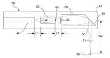
- FIG. 5Aschematically illustrates an OCT probe having a reduced form factor suitable for use in a catheter that employs a compound lens in order to increase a transverse resolution without increasing a relative size of the form factor, as compared to the prior art OCT probe of FIG. 2A ;
- FIG. 5Bschematically illustrates an OCT probe similar to that illustrated in FIG. 5A , in which an optically transparent member is fused to a distal end of a single mode optical fiber and a proximal end of a first lens element, a linear dimension of the optically transparent member enabling a dimension of a first object distance L 1 to be precisely controlled and the probe to be mechanically robust;
- FIG. 5Cgraphically illustrates the relationship between working distance (W), object distance (L 2 ), and transverse resolution that can be achieved using the OCT probe of FIG. 5B , which employs first and second GRIN lenses;
- FIG. 5Dschematically illustrates another OCT probe based on the probe of FIG. 5A , in which both a first object distance L 1 and second object distance L 2 can be precisely controlled;
- FIG. 5Egraphically illustrates the relationship between working distance, object distance L 2 , and transverse resolution that can be achieved using the OCT probe of FIG. 5B with a second GRIN lens having a shorter pitch length as compared with the second GRIN lens for the relationship of FIG. 5C (note the dramatic differences in object distance L 2 for a working distance of 8 mm in FIGS. 5C and 5E );
- FIG. 5Fschematically illustrates yet another OCT probe based on the probe of FIG. 5D , in which both a first object distance L 1 and second object distance L 2 are precisely controlled by selecting a second GRIN lens having shorter pitch length as compared with the second GRIN lens for the relationship of FIG. 5C ;
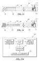
- FIG. 6is a functional block diagram of an OCT system incorporating the OCT probe of FIG. 5B , to enable esophageal OCT imaging to be used to detect Barrett's esophagus;
- FIG. 7Ais an esophageal OCT image acquired using a system substantially identical to that illustrated in FIG. 6 , illustrating that circumferential esophageal OCT imaging is achievable;
- FIG. 7Bis an esophageal OCT image acquired using a system substantially identical to that illustrated in FIG. 6 , illustrating that three-dimensional spiral esophageal OCT imaging is achievable;
- FIG. 8schematically illustrates an OCT probe including a compound lens formed from three GRIN lenses
- FIG. 9schematically illustrates an OCT probe configured for image guided needle biopsy
- FIG. 10Aschematically illustrates an OCT probe incorporated into a stainless steel hypodermic needle
- FIG. 10Bschematically illustrates the relative sizes of the OCT probe of FIG. 10A and a U.S. 10 cent coin (i.e., a dime);
- FIG. 10Cis an OCT image including muscle fiber bundles obtained using the OCT probe of FIG. 10A , graphically illustrating that relatively small structures can be visualized in OCT images acquired using the OCT probe of FIG. 10A ;
- FIG. 10Dgraphically illustrates the relationship between working distance, object distance, and transverse resolution that can be achieved using the OCT probe of FIG. 10A ;
- FIG. 11schematically illustrates an OCT probe incorporated into a transparent inner housing, the inner housing being small enough to be inserted into a stainless steel hypodermic needle;
- FIG. 12graphically illustrates the relationship between working distance, lens pitch, and transverse resolution that can be achieved using the OCT probe of FIG. 11 ;
- FIG. 13schematically illustrates an OCT probe incorporated into a transparent inner housing, the inner housing being small enough to be inserted into a stainless steel hypodermic needle, in which the OCT probe includes an optically transparent spacer between a distal end of a single mode optical fiber and a proximal end of a GRIN lens, the spacer enabling a desired resolution to be achieved at a given working distance;
- FIG. 14schematically illustrates an OCT probe incorporated into a transparent inner housing, the inner housing being small enough to be inserted into a stainless steel hypodermic needle, in which the OCT probe includes a compound lens including three different GRIN lens, the compound lens enabling a desired resolution to be achieved at a given working distance;
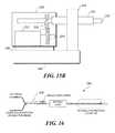
- FIG. 15Ais a functional block diagram of an OCT system incorporating one or more of the exemplary OCT probes of FIGS. 10A , 11 , 13 , and 14 , to enable OCT image guided needle biopsy;
- FIG. 15Bschematically illustrates an exemplary OCT system incorporating one or more of the exemplary OCT probes of FIGS. 10A , 11 , 13 , and 14 , to enable OCT image guided needle biopsy;
- FIG. 16is a functional block diagram of an OCT system incorporating a laser for marking a region of interest, where the laser light is delivered using the same optical fiber that is used for OCT imaging;
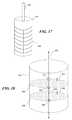
- FIG. 17schematically illustrates an exemplary OCT balloon catheter including electrodes on an outer surface of the balloon enabling marking to be implemented using electrocauterization
- FIG. 18schematically illustrates a lumen marked using ink dots.
- One application of the concepts disclosed hereinis to use OCT imaging to detect sub-squamous Barrett's esophagus (and other sub-squamous abnormal structures such as cancer).
- OCToptical coherence tomography
- FIGS. 3A and 3CRepresentative OCT images are shown in FIGS. 3A and 3C , with FIGS. 3B and 3D showing corresponding histological images obtained using microscopic techniques.
- features that can be identified in the OCT image of FIG. 3A and the corresponding histological imageinclude normal glycogenic squamous epithelium (GSE), an ulcer (erosion), a basal cell layer (BCL), and lamina intestinal (LP).
- GSEnormal glycogenic squamous epithelium
- BCLbasal cell layer
- LPlamina propria
- features that can be identified in the OCT image of FIG. 3Aas well as the corresponding histological image of FIG. 3B , indicating that such features can be readily identified in OCT images.
- Features that can be identified in the OCT image of FIG. 3Cinclude sub-squamous Barrett's epithelium (SBE) and some blood vessels (BV).
- SBEsub-squamous Barrett's epithelium
- BVblood vessels
- such featuresare readily apparent in both the OCT image of FIG. 3C as well as the corresponding histological image of FIG. 3D , thus indicating that sub-squam
- OCT imagingoffers a more than 80% sensitivity and 90% specificity for detecting sub-squamous Barrett's esophagus.
- the main reason for a false positive diagnosisis the difficulty in distinguishing sub-squamous Barrett's glands from large blood vessels; however, this would not be a problem in an in vivo environment, because in vivo blood flow will enable blood vessels to be differentiated from sub-squamous Barrett's esophagus (i.e., in vivo Doppler imaging will enable blood vessels to be differentiated from Barrett's glands, as there will be no blood flow in the Barrett's structures).
- OCT imaging of internal organshas been made possible by the development of flexible and miniature fiber-optic OCT catheters, such as the OCT probe of FIG. 2A .
- the small diameter (1-2.5 mm) of an OCT catheterpermits its delivery through the working channel (3.7 mm in diameter) of a standard GI endoscope.
- the procedureis to choose a region of interest under the field of view of a GI endoscope, deliver the OCT catheter to the region, and acquire high-resolution images in situ.
- two possible scanning modeslinear scan and circumferential scan
- an OCT balloon catheteris used that integrates circumferential OCT imaging and position stabilization.
- Such an exemplary OCT balloon catheter 90is schematically illustrated in FIG. 4 .
- an OCT probeis introduced into an inner lumen 94 of the catheter, and an additional lumen (not specifically shown) enables pressurized air (or some other fluid) to be supplied to inflate a balloon 106 that is included on the catheter.
- At least the portion of lumen 94 overlapping balloon 106can be made of a generally optically transparent material, to enable a light beam 104 emitted from OCT optics 102 (and deflected by a reflector 98 , which can comprise a micro prism) to reach a sample.
- a reflector 98which can comprise a micro prism
- Additional elements of the OCT probeinclude a single mode optical fiber 100 , disposed within a hollow metal drive wire 92 , which enables the OCT probe to be selectively positioned within lumen 94 .
- OCT optics 102can be enclosed in a durable housing 96 (such as a metal or glass housing), which includes an opening or transparent window adjacent to reflector 98 to enable light to reach a sample area.
- the function of the balloonis to flatten out or generally reduce the esophageal folds and stabilize the OCT catheter.
- the radius of the balloon required to perform this functionis about 8-15 mm (when inflated), which is approximately the radius of a human esophagus when the esophageal folds are flattened. Consequently, a relatively large working distance (i.e., ⁇ 8-15 mm) is required for the OCT catheter, which imposes a significant challenge in creating a usable optical design that can: (1) provide a reasonably useful transverse resolution; and, (2) maintain a small catheter diameter (e.g., 2 mm or less), so that the entire balloon catheter can still be delivered to the esophagus through the working channel of a GI endoscope.
- yet another aspect of the concepts disclosed hereinis an optical design that achieves a high transverse resolution ( ⁇ 20-40 ⁇ m) in a compact form factor (i.e., having a diameter that is less than or equal to about 1.5 mm), with a working distance sufficient for enabling the OCT optics to be spaced apart from the esophageal wall to achieve the circumferential imaging noted above.
- Effective parameters for such an optical designinclude a target transverse resolution of approximately 20-40 ⁇ m, a working distance of approximately 8-15 mm, and an overall optical diameter of less than or equal to 1.5 mm.
- a major challenge in developing such a probeis achieving the relatively high transverse resolution target, while maintaining a small diameter (e.g., 1.5 mm).
- the working distance and transverse resolutioncan be tuned by changing the object distance L 1 (i.e., the distance between a distal tip of single mode optical fiber 44 and the proximal surface of GRIN lens 46 ).
- the calculated transverse resolution and working distance for such a designare shown in FIG. 2B , as noted above.
- the best transverse resolution for an 8-mm working distance(required for esophageal imaging), given the probe design of FIG.
- novel concepts disclosed hereinprovide a catheter-sized OCT probe design that achieves a higher resolution with the same minimal form factor, by employing a miniature compound lens, in which a first lens element tightly focuses the beam and effectively increases the beam's NA (by a factor of about 2), and a second lens element that refocuses the beam with the increased NA to the desired working distance (about 8 mm for esophageal imaging, although other working distances may be desirable for different imaging applications).
- FIG. 5Aschematically illustrates an OCT probe 60 having a reduced form factor suitable for use in a catheter, and which employs a compound lens in order to increase a transverse resolution without increasing a relative size of the form factor, as compared to the Prior Art OCT probe of FIG. 2A .
- the novel OCT probe of FIG. 5Asatisfies the design criteria noted above.
- OCT probe 60includes housing 42 , into which a distal portion of single mode optical fiber 44 , a first GRIN lens 62 (having a focused beam spot size 64 at the exit surface of GRIN lens 62 ), a second GRIN lens 66 , and a reflector 48 are disposed.
- optical elementsi.e., the single mode optical fiber, the first and second GRIN lenses, and the reflector
- L 1 and L 2correspond to the thickness of the optical cement layer bonding the adjacent optical components.
- OCT probe 60 aAssembling multiple miniature lenses requires precision alignment, and the object distance between any two adjacent elements (e.g., L 1 and L 2 in FIG. 5A ) should be accurately controlled.
- a slightly modified OCT probe 60 a(as illustrated in FIG. 5B ) was designed.
- an optically transparent member 70(preferably implemented by a glass or plastic rod) is disposed in object distance L 1 (between a distal end of single mode optical fiber 44 and first GRIN lens 62 ).
- the first GRIN lenswas implemented using a miniature GRIN rod lens (or a GRIN fiber-optic lens), and the second GRIN lens was implemented using a conventional GRIN lens.
- the length of the glass rod and the GRIN fiber optic lens(i.e., first GRIN lens 62 ) can be precisely controlled by cleaving, with an accuracy of ⁇ 5 ⁇ m (or better).
- the glass rod fiber(optically transparent member 70 ) is thermally fused to a distal end of the single mode optical fiber and a proximal end of the first GRIN lens.
- This configurationenables the object distance L 1 to be controlled with great precision (note that as indicated in FIG. 5C and as discussed in detail below, the resolution is a function of object distance (both L 1 and L 2 ); thus, controlling the object distance with precision enables resolution to be predicted and controlled with precision).
- the distal end of first GRIN lens 62is fixedly attached to a proximal end of second GRIN lens 66 using optical cement, and the distal end of the second GRIN lens is fixedly attached to the reflector using the same technique.
- n(r)n 0 (1 ⁇ 2 r 2 /2).
- L 5Cshows L 2 , but not L 1 , a similar relationship can be graphed for L 1 ), a 0.369 mm long GRIN fiber lens for first GRIN lens 62 , a conventional GRIN lens of 0.25 pitch and a 1.0 mm diameter for second GRIN lens 66 , and a separation of ⁇ 220 ⁇ m between the first GRIN lens and the second GRIN lens (i.e., object distance L 2 is ⁇ 220 microns).
- the diameter of all the opticswill be less than 1.2 mm, achieving a form factor that can be easily integrated with a double-lumen balloon (such as those available from Wilson-Cook, Winston Salem, N.C.), having a 2.2 mm diameter transparent inner lumen, and an outer diameter of about 8 mm when the balloon is inflated.
- a double-lumen balloonsuch as those available from Wilson-Cook, Winston Salem, N.C.
- four different variablesdetermine the resolution and working distance: (1) the parameters of GRIN lens 62 (pitch and ⁇ -value); (2) the dimension of object distance L 1 ; (3) the parameters of GRIN lens 66 (pitch and ⁇ -value); and (4) the dimension of object distance L 2 .
- These variablescan be varied as desired until a useful resolution and working distance are achieved.
- the following exemplary techniques for defining these four variablesare intended to be exemplary, rather than limiting.
- the form factor of the probewill limit the diameter of GRIN lenses that can be employed (probes for relatively smaller lumens will require relatively smaller diameter GRIN lenses).
- Limiting GRIN lens 62 to lenses that have approximately the same diameter as the optical fibercan facilitate manufacture of the OCT probe, because thermal fusion between components having the same general diameter is relatively straightforward.
- GRIN lens 62must also have a relatively large ⁇ -value.
- the first object distance L 1(optically transparent member 70 in FIG. 5B , or in some cases, a relatively thin layer of optical cement) and the pitch length of GRIN lens 62 (i.e. a GRIN fiber lens) are defined by varying the parameters of L 1 and GRIN lens 62 to minimize the focused beam spot size 64 at the exit surface of GRIN lens 62 , while ensuring the beam is not clipped within the glass rod (L 1 ) or GRIN lens 62 (each of which are preferably of the same diameter of the single mode optical fiber, i.e. 125 um).
- the objective distance L 2 between GRIN lens 62 and GRIN lens 66 , and parameters for GRIN lens 66are then varied to achieve the designed working distance, and the transverse resolution of the entire probe can be found for the designed working distance using Gaussian beam optics.
- L 2is intentionally minimized, so that GRIN lens 62 and GRIN lens 66 are coupled together each other with optical cement (thus, L 2 is implemented using optical cement).
- L 2is varied to include dimensions longer than can be readily implemented using optical cement, and in such embodiments an optically transparent spacer (such as a glass rod) can be used to implement L 2 .
- an optically transparent spacersuch as a glass rod
- a beam deflecting element 48(if required) is attached to GRIN lens 66 with optical cement.
- L 1 and the pitch length of GRIN lens 62can also be selected (along with object distance L 2 ) using Gaussian beam optics with a multiple parameter search, so that the smallest focused beam spot is achieved at the final desired working distance (e.g. 8-15 mm) without causing beam clipping within the glass rod and the GRIN fiber lenses.
- a unique feature of such a balloon imaging catheteris its large working distance, which is achieved while still maintaining a small focused spot size (i.e., high lateral resolution) and a small diameter (permitting the deployment of the balloon catheter into the esophagus through the standard accessory port of a GI endoscope).
- Such an OCT imaging catheterenables high-resolution circumferential imaging of the entire human esophagus.
- the disclosed compound lens catheter design (1)offers a much better transverse resolution at a given long working distance (e.g.
- the large working distance, high lateral resolution, and small overall diameterare achieved by using a compound lens made of several rod lenses and spacers ( FIG. 5B ; noting that a spacer can be disposed between GRIN lens 62 and GRIN lens 66 when L 2 is larger than can be accommodated using optical cement).
- a spacercan be disposed between GRIN lens 62 and GRIN lens 66 when L 2 is larger than can be accommodated using optical cement.
- optical cementis very challenging, if the object distance (i.e., L 1 or L 2 ) is larger than the diameter of the smaller of the GRIN lens (or optical elements) being joined.
- optical cementis not as mechanically robust or stable as thermal fusion, thus when possible thermal fusion is preferred.
- thermal fusioncan be used to connect at least some elements.
- a glass rod spacer used to implement L 1is thermally fused to a single-mode fiber, and then cleaved to the desired dimension for L 1 .
- the glass rodis then fused to the GRIN fiber (or rod) lens used to implement GRIN lens 62 .
- That GRIN lensi.e., GRIN lens 62
- GRIN lens 66is coupled to GRIN lens 62 with optical cement, with the object distance L 2 precisely tuned (e.g. by a precision micron translation stage) to achieved the designed working distance.
- L 2is implemented with a spacer
- that spacer and GRIN lens 66can be similarly fused together and precisely cleaved, followed by joining [spacer (L 1 )+GRIN lens 62 ] to [spacer (L 2 )+GRIN lens 66 )] together with optical cement, enabling precise control of the dimension of L 1 and L 2 , and the pitches (i.e., lengths) of each GRIN lens.
- these componentscreate a compound lens that enables the catheter to achieve the desired working distance, while maintaining an acceptably small focused spot size.
- a micro-prism or beam deflectoris used to redirect the beam 90°, into the tissue.
- a prototype of such an OCT probewas successfully constructed and exhibited a working distance of 9.6 mm, and a measured focused spot size of 39 ⁇ m.
- Circumferential OCT imagingcan be performed by rotating the imaging catheter of FIG. 4 within the double lumen balloon.
- a spiral scanning patterncan be achieved by pulling back the OCT catheter while it is being rotated.
- This approachis analogous to spiral CT and 3-D intravascular ultrasound (IVUS) imaging.
- the 3-D structure of the esophageal wallcan be reconstructed from the spiral scan by using standard computer interpolation algorithms.
- a computer-controlled direct current (DC) motor with an accurate position encodercan be used to perform pull-back. The pull-back speed will depend on the imaging acquisition speed, the circumferential pixel density, and the spiral scan pitch.
- DCdirect current
- each circumferential scanwill take about 2 ⁇ *8 mm/20 ⁇ m(30,000 s ⁇ 1 ), or about 0.08 seconds for a balloon having an 8 mm radius.
- the spiral scan pitchis 50 ⁇ m, a pull-back speed of about 0.6 mm/sec would be required, which is readily achievable.
- the rotation, pull back and data acquisitioncan be controlled and synchronized by software for the spiral 3D imaging.
- a key component for implementing circumferential scanningis a fiber-optic rotary joint, which couples light from a rotating catheter to a stationary source fiber.
- the rotary jointis disposed at a proximal end of a catheter, providing a convenient way to switch catheters.
- a working exemplary prototype embodiment of a compact rotary joint having dimensions of about 1.5 cm in diameter and about 8 cm in lengthhas been successfully fabricated.
- Such a rotary jointcan be coupled to a spiral-scan pull-back motor and incorporated into a single handheld unit, facilitating manipulation of the balloon imaging catheter of FIG. 4 .
- This type of handheld unitwill be suitable for use in an in vivo or a clinical environment.
- mechanisms for rotating the micro-prism or reflector disposed at the distal end of the OCT probecould be employed to achieve the circumferential scanning, with a lateral translation stage being employed to achieve the spiral scanning.
- FIG. 5Dschematically illustrates an OCT probe 60 b in which variations in L 2 enable different working distances and resolutions to be achieved, as graphically indicated in FIG. 5C .
- OCT probe 60 aincludes single mode optical fiber 44 , first GRIN lens 62 , a spacer 45 disposed between the optical fiber and the first GRIN lens (i.e., spacer 45 is L 1 ), second GRIN lens 66 , a spacer 47 between the first GRIN lens and the second GRIN lens (i.e., spacer 47 is L 2 ), and reflector 48 .
- Spacer 47can be implemented by a controlled thickness of an adhesive such as optical cement, a physical spacer having a predefined thickness (such as a cylindrical or ring shaped plastic mass), or a combination of cement and physical spacer. Exemplary techniques for determining the lengths (L 1 , the length of the GRIN fiber lens and L 2 ) are described above.
- FIG. 5Fschematically illustrates an OCT probe 60 c in which GRIN lens 66 has a relatively shorter pitch length, and the desired dimension of a spacer for L 2 is sufficiently large that the use of optical cement alone would be impractical.
- the relationship between L 2 , working distance and resolution for OCT probe 60 cis graphically indicated in FIG. 5E .
- OCT probe 60 cincludes single mode optical fiber 44 , first GRIN lens 62 , spacer 45 disposed between the optical fiber and the first GRIN lens (i.e., spacer 45 is L 1 ), second GRIN lens 66 , a spacer 49 between the first GRIN lens and the second GRIN lens (i.e., spacer 49 is L 2 ), and reflector 48 .
- Spacer 49is implemented using a plastic or glass rod that is substantially transparent to the wavelengths of light that are emitted and received by OCT probe 60 c , because spacer 49 is too long to implement using optical cement alone.
- FIG. 6schematically illustrates an OCT system incorporating the OCT probe of FIG. 5B , to enable esophageal OCT imaging to be used to systematically detect Barrett's and sub-squamous Barrett's esophagus, using either circumferential scanning or spiral three-dimensional scanning, generally as discussed above.
- a system 110includes an OCT probe 112 (substantially similar to the esophageal OCT catheter probes discussed above), a rotary joint 114 , a pull-back stage 116 (with one or more prime movers to rotate and linearly translate the OCT probe, the rotary joint and pull-back stage optionally being enclosed in a common housing 115 ), a controller 118 (e.g., implemented using a processor and a memory storing machine instructions executed by the processor, although such a controller can also be implemented using a custom logic circuit), and additional required OCT components (generally consistent with the OCT system of FIG. 1 ).
- OCT probe 112substantially similar to the esophageal OCT catheter probes discussed above
- a rotary joint 114includes a rotary joint 114 , a pull-back stage 116 (with one or more prime movers to rotate and linearly translate the OCT probe, the rotary joint and pull-back stage optionally being enclosed in a common housing 115 ), a controller 118 (e
- the prime movercan rotate the rotary joint via a timing belt, and the rotary joint along with the prime mover can be linearly translated using a precision motorized stage.
- the combination of rotation and linear translationachieves a spiral beam scanning pattern for performing spiral 3-D volumetric imaging.
- Real-time OCT imaging using a balloon catheter based on the exemplary embodiments of FIGS. 4 and 5Bwas experimentally demonstrated using a standard swept source OCT system modified to generally correspond to the system of FIG. 6 .
- This exemplary OCT systemutilized a 1310 nm swept laser source with a Full Width at Half Maximum (FWHM) bandwidth of 106 nm and a sweeping frequency of 6 kHz, corresponding to an imaging speed of 12,000 axial scans per second.
- the line width of the swept sourceis about 0.15 nm corresponding to an imaging depth of ⁇ 2 mm.
- the measured axial resolutionwas 8.5 ⁇ m.
- the systemhad a signal-to-noise ratio of about 120 dB at 6.5 mW incident power on the sample.
- OCT images from a pig esophaguswere acquired. The deflated balloon catheter was inserted into the pig esophagus and then fully inflated.
- FIG. 7Ais a circumferential esophageal OCT image of a pig esophagus acquired using the system described above (i.e., a system substantially identical to that illustrated in FIG. 6 ), illustrating that circumferential esophageal OCT imaging is achievable.
- the image sizeis ⁇ 2 mm ⁇ 60 mm (2000 ⁇ 3000 pixels, axial x circumferential). Note that the void space in the middle of the image is not to actual scale, the void has been included purely for the purpose of enlarging the display of the tissue portion of the image.
- the imaging frame ratewas 4 Hz, which can be significantly improved upon by using a faster swept source or spectral domain OCT system.
- the identifiable layersinclude the epithelium (E) 124 , lamia intestinal (LP) 126 , muscularis mucosa (MM) 128 , submucosa (SM) 130 , and muscularis propria (MP) 132 .
- FIG. 7Bis an esophageal OCT image of a pig esophagus acquired using the system described above (i.e., a system substantially identical to that illustrated in FIG. 6 ), illustrating that three-dimensional spiral esophageal OCT imaging is achievable (note that the pitch displayed is not to scale, since the Figure is purely for illustration).
- the experimental pitch length of the spiralis about 20 ⁇ m.
- the exemplary balloon imaging catheter(based on FIGS. 4 and 5B ) provides 2-D and 3-D images of esophageal tissue.
- the catheterovercomes limitations in conventional OCT endoscope design and provides a simple scan mechanism, permitting methodical imaging of the entire esophagus for Barrett's (surface and sub-squamous) surveillance and cancer detection to be achieved.
- OCT imagingcan be used to detect Barrett's esophagus, and for analyzing the collected images for structures corresponding to the sub-squamous Barrett's glands of FIG. 3C .
- the presence of blood flowwill enable blood vessels and Barrett's structures to be easily differentiated.
- FIG. 8An exemplary embodiment is schematically illustrated in FIG. 8 .
- the compact form factor, shorter working distance, and high spatial resolutionare achieved by using a compound lens comprising three different GRIN lenses. While additional GRIN lenses could be employed, it should be noted that optical losses are associated with the connecting (e.g. by thermal fusion) multiple GRIN lenses, and employing more than three GRIN lenses to achieve a compound lens may lead to unacceptable optical losses.
- a distal end of a single mode optical fiber 78is stripped of its protective coating 76 , and is coupled to a compound lens formed of three GRIN lenses 80 , 82 , and 84 .
- a reflector 86directs a light beam 88 through an opening in a housing 74 toward a sample 90 .
- an optical window 73fills the opening, although an inner optically transmissive housing encompassing the compound lens can also be employed.
- Fabrication of OCT probe 72is accomplished by thermally fusing a distal end of single mode optical fiber 78 to GRIN lens 80 , and thermally fusing GRIN lens 80 to GRIN lens 82 .
- GRIN lens 84is coupled with GRIN lens 82 either by thermal fusion (or by using optical cement if the thermal fusion loss is not acceptable due to the mismatch of the diameters).
- the design conceptis generally the same as discussed above with respect to the exemplary OCT probes of FIGS. 5A and 5B , in that the proximal compound lens elements (GRIN lenses 80 and 82 ) tightly focus light emitted from the distal end of the single mode optical fiber, while the distal lens element (GRIN lens 84 ) refocuses the beam to a desired working distance with a high transverse resolution.
- GRIN lens 80is implemented using a 0.25-pitch length lens that collimates the beam from the single mode optical fiber.
- GRIN lens 82is also implemented using a 0.25-pitch length lens; however, the middle GRIN lens has more focusing power (e.g., GRIN 82 has a larger ⁇ -value than does GRIN lens 80 ).
- GRIN lens 82focuses the collimated beam to a smaller spot at its exit surface, and the new focused spot size is provided by the following relationship:
- D 2n o ⁇ ⁇ 1 ⁇ ⁇ 1 n o ⁇ ⁇ 2 ⁇ ⁇ 2 ⁇ D 1 ( 1 )
- D 1is the input spot size for GRIN lens 80 (i.e., the mode field diameter of the single mode optical fiber)
- ⁇ 1is the ⁇ -value of GRIN lens 80
- ⁇ 2is the ⁇ -value of GRIN lens 82
- n o1is the on axis refractive index of GRIN lens 80
- n o2is the on axis refractive index of GRIN lens 82 .
- GRIN lens 84has a lower focusing power than the other GRIN lenses, but a larger aperture, and GRIN lens 84 images the focused spot D to a final focused spot.
- the pitch number of GRIN lens 84can be selected to achieve a desired working distance.
- Customized GRIN fiber lenses(having a diameter of about 125 microns) can be used to implement GRIN lenses 80 and 82 , and a commercially available GRIN lens (having a diameter of about 250 ⁇ m) will be used to implement GRIN lens 84 .
- the single mode optical fiber, GRIN lens 80 , and GRIN lens 82will be thermally fused in tandem, and each of GRIN lens 80 and GRIN lens 82 will be precisely cleaved to achieve a 0.25 pitch length. Because the aperture of GRIN lens 84 is larger than the aperture of the other GRIN lenses, beam vignetting within GRIN lens 84 is prevented. GRIN lens 84 is attached directly to GRIN lens 82 with optical cement, and no appreciable space is required between the two.
- Gaussian calculationsindicate that the final beam focused spot size will be about 7.1 microns, at a working distance of about 500 microns, using a 0.327-pitch length GRIN lens for GRIN lens 84 .
- a spot sizerepresents a 200% reduction (i.e., improvement) compared to a traditional single GRIN lens approach.
- the resultant high transverse resolutionwill be appreciated when considering the small optics diameter (125-250 microns) and the working distance achieved (e.g. 500 microns, which is sufficient to enable the focus to be disposed in tissue that can be placed in direct contact with the beam window of the miniature probe).
- This transverse resolutionwill be close to the axial resolution produced by the 1300 nm light source commonly employed in OCT systems.
- All three GRIN lenses and the reflectorcan be encased within a protective glass tube (a durable quartz glass having good optical and structural properties is employed in an exemplary embodiment).
- a protective glass tubea durable quartz glass having good optical and structural properties is employed in an exemplary embodiment.
- Previous designshave employed polished optical cement for the optical window. However, polished optical cement can be easily scratched, significantly reducing optical clarity and the service lifetime of the imaging probe.
- the use of a glass housingeliminates this problem. If desired, matching fluid can be used to fill any void spaces within the glass housing to reduce undesired back reflection or beam profile distortion.
- Yet another aspect of the present inventionis directed to incorporating OCT imaging into needle biopsy probes, to achieve image guided needle biopsy.
- Such technologycan perform high-resolution, microscopic imaging of biological tissues in vivo and in real-time. This technology will permit real-time assessment of the tissue in situ by providing structural and/or quantitative information before tissue removal, leading to improved tissue sampling accuracy and reduced biopsied tissue volumes, thereby making biopsy less invasive.
- the depth-dependent OCT signalscan be analyzed to obtain localized tissue optical properties, which are related to cellular morphologies such as the shape, size and density of the cell organelles and nuclei. Significantly, such properties can be altered by neoplastic changes, and thus such properties might be used to detect morphological changes.
- the quantitative informationcan then provide objective evaluation of the target “suspicious” tissue. This can be very complementary to structural imaging, in particular, when the lesion is homogeneous as in the case of poorly differentiated adenocarcinoma. The quantitative information would also allow systematic comparison between normal and pathologic tissues.
- the high-resolution morphologic imaging and the quantitative information about localized tissue optical propertiesenhance the OCT needle probes capability of targeting pathologic tissues of small volumes for biopsy.
- the development of a 27-gauge (or 400 ⁇ m diameter) OCT imaging needleenables interstitial high-resolution imaging of solid tissues/organs beyond a depth of 1-3 mm, which is about as deep as can be achieved when performing OCT imaging from outside the tissue.
- the OCT imaging needleincludes passive fiber-optic components, and can be directly introduced into tissue with no electric hazard. Preliminary studies have demonstrated that the small diameter of the OCT needle does not cause visible bleeding or trauma when introduced into solid tissue.
- FIG. 9schematically illustrates an exemplary OCT image-guided biopsy probe 150 that includes an imaging needle 152 , with OCT optics, and a biopsy needle 154 (including a biopsy window 156 , configured to extract a relatively small portion of tissue for analysis).
- OCT image-guided biopsy probe 150can be positioned proximate a mass of tissue 158 , so that needle 152 can be advanced into the tissue.
- An optical beam 160 emitted from a distal end of needle 152enables a generally cylindrical region of tissue 162 to be imaged (by rotating the optics in the needle, generally as discussed above with respect to circumferential and 3-D spiral scanning). Should any of the imaged tissue indicate a sample of tissue is required, biopsy needle 154 is advanced into the tissue to obtain a sample.
- imaging needle 152when imaging needle 152 is implemented using a 27-gauge needle, the resulting imaging needle is significantly smaller than conventional 11 - 18 gauge core biopsy needles.
- the small size and the capability of imaging tissue micro-anatomymake such an OCT imaging needle an excellent candidate to be integrated with a biopsy needle, for providing image guidance in situ.
- Interstitial imagingcan be performed by rotating the needle using a computer controlled precision DC motor with the image plane perpendicular to the rotation axis, generally as discussed above with respect to esophageal scanning. Imaging at various planes can be achieved by inserting or retracting the OCT needle and a 3-D image can be constructed using well-established computer algorithms such as are used in spiral CT.
- An imaging penetration depth of approximately 1-3 mmresults in a cylindrical imaged tissue volume of 2-6 mm in diameter and several millimeters to centimeters in length with a single needle insertion. This result is a significant improvement compared to what is provided by taking a 1-mm diameter core biopsy specimen in a conventional approach. Since the imaged area scales as the square of the diameter, needle-based OCT can evaluate volumes 4 times to 36 times larger than that of a single 1 mm diameter core biopsy. As noted above, the OCT imaging needle is inserted through the biopsy needle into the lesion, and high-resolution interstitial images are then taken along the insertion path.
- the core biopsy needlecan then slide over the OCT needle to the target region to withdraw a biopsy sample.
- the OCT imaging needlewill then be retracted and standard tissue biopsy can then be performed on the specimen taken.
- the relatively small size of such an OCT needlewould dramatically reduce the chance of blocking the conventional image-guidance for directing needle biopsy.
- FIG. 10Aschematically illustrates an OCT probe 164 , where an outer housing 166 comprises a 27-gauge hollow steel needle having a sharpened tip 168 .
- a distal end of a single mode optical fiber 170is coupled to a 250 micron diameter GRIN lens 172 using a layer of optical cement 179 .
- Lens 172directs a light beam 176 from the single mode optical fiber to a reflector 174 , through an optical window 177 made of polished optical cement (which also attaches lens 172 to reflector 174 ) toward a sample 178 .
- FIG. 10Bshows the size of OCT probe 164 relative to a U.S. ten cent coin 180 (i.e., a dime).
- exemplary OCT probe 164Key design parameters considered in developing exemplary OCT probe 164 included: (1) the imaging beam focused spot size (which determines the transverse resolution); and, (2) the working distance, which is the distance between the distal end-surface of the GRIN lens to the beam focus.
- the focused spot size and working distanceare controlled by the “object distance,” i.e., the separation between the single mode optical fiber tip and the GRIN lens.
- FIG. 10Dgraphically illustrates these two parameters versus the object distance, as calculated using Gaussian optics.
- 10Dcan be used to determine the object distance that will enable the required working distance to be achieved, while also enabling a determination to be made as to whether the selected working distance/object distance combination will achieve an acceptable resolution (spot size), for a given GRIN lens.
- the required shortest working distancewill be equal to the needle diameter, in order to have the beam focus outside of the needle.
- an optimal working distance of ⁇ 500 ⁇ mwas selected, to enable the OCT needle imaging probe to have the flexibility to set the position of the focal point outside the optical window (e.g., by adjusting the distance between the GRIN lens and the 90° reflector).
- the smallest focused spot size corresponding to a 500 ⁇ m working distancewill be 11 ⁇ m.
- FIG. 10Cshows an OCT image obtained using an exemplary prototype device corresponding to OCT probe 164 .
- Imagingwas performed using a 1300 nm light source with axial resolution of ⁇ 5 ⁇ m (in tissue).
- the sector imageincludes 625 ⁇ 1250 pixels (i.e., circumferential ⁇ radial). No bleeding from needle insertion was observed as the image was acquired.
- the imagewas obtained using an optical window comprising polished optical cement (i.e., a relatively poor quality optical window). Improvements in distal end beam focusing optics and optical window design should yield significant improvements in image quality.
- OCT probe 164is small ( ⁇ 400 ⁇ m in diameter) and can easily pass through the core of an 18-gauge biopsy needle, which has an inner diameter of about 1.6 mm.
- the optical components at the needle's distal endwere glued together, and an optical window was produced by polishing the optical cement disposed at the distal end. Because optical cement is not as strong as glass, the optical window surface was easily damaged/scratched when the needle was introduced into soft tissue, causing severe degradation of image quality or failure to acquire any image at all.
- the miniature GRIN lens(250 ⁇ m in diameter) was assembled manually (i.e., joined to the distal end of the single mode optical fiber and coupled to the reflector) within the needle, making it extremely difficult to control the position of the GRIN lens relative to the other miniature optical components. Consequently, imaging beam parameters, such as the focused spot size and the working distance, were difficult to adjust, and these parameters were often achieved by trial and error.
- the engineering protocolwas delicate and tedious, resulting in high fabrication costs, rendering the design impractical for mass production.
- FIG. 11schematically illustrates such an exemplary OCT probe 190 , where an inner housing 192 comprises a quartz glass tube having a diameter sufficiently small to enable the quartz glass tube to fit inside the 27-gauge hollow steel needle employed in OCT probe 164 of FIG.
- a distal end of single mode optical fiber 170is thermally fused (thus eliminating any object distance at this location) to a 125 micron diameter GRIN lens 172 a .
- GRIN lens 172 aa distal end of single mode optical fiber 170 is thermally fused (thus eliminating any object distance at this location) to a 125 micron diameter GRIN lens 172 a .
- 125 ⁇ m diameter vs. 250 ⁇ m diameterenables the optics to be placed inside the quartz glass tube inner housing.
- GRIN lens 172 adirects light beam 176 from the single mode optical fiber to reflector 174 , through the quartz glass tube (which functions as a housing and a high quality optical window) and a beam window 173 (i.e., an opening in the hollow steel needle; noting that if the inner transparent tube is not employed, beam window 173 can be filled with an optically transmissive material, rather than simply being an opening) toward a sample 178 .
- the GRIN fiber lenswhich has the same bare optical fiber diameter as the single mode optical fiber (e.g., 125 ⁇ m in diameter), which in addition to fitting inside the quartz glass tube also facilitates alignment during thermal fusion. After fusing the single mode optical fiber and the GRIN fiber lens, the GRIN lens can be cleaved at the appropriate length, according to the designed focused spot size and working distance.
- Probe 190can utilize a customized GRIN fiber lens, which has a smooth refractive index profile as described by the above equation.
- Gaussian opticsthe working distance and the focused spot size versus the pitch number of the GRIN fiber lens can be calculated. Again, an optimal working distance of ⁇ 500 ⁇ m is selected (for a 27-gauge needle), and this configuration leads to a corresponding focused spot size (or transverse resolution) of approximately 14.5 ⁇ m, when a 0.36-pitch (or 1.41 mm long) GRIN fiber lens is used.
- the fusion junction between the single mode optical fiber and the GRIN lenshas proven to be mechanically strong and optically transparent. Such fabrication techniques are straightforward, fast, cost-effective, and no manual alignment is required.
- a quartz glass inner housing(inner in that the quartz glass housing, while encompassing the OCT optics, is designed to fit within the outer 27-gauge hollow needle) solves the durability issue for the optical window.
- those elements and the micro reflectorare introduced into a small fused silica tube (e.g., of an inner diameter of 150-250 ⁇ m and a wall thickness of 100-50 ⁇ m).
- the inner glass housingis then placed into (and secured using glue, epoxy, or optical cement) the hypodermic needle, which includes a pre-cut opening through which light can pass.
- the fused silica tubewill be in direct contact with the tissue, and the glass is much more scratch-resistant than the polished optical cement window of OCT probe 164 .
- Stainless hypodermic tubes of different sizes (23-gauge to 27-gauge) or wall-thicknesscan be chosen to achieve desired mechanical strength and flexibility. The distal end of the hypodermic tube will be sharpened to facilitate the needle insertion into solid tissues.
- the focused spot sizecan be reduced by increasing the distance between a given GRIN lens and the distal tip of the single mode optical fiber.
- a glass rodfor example, one having an outer diameter substantially equal to that of the single mode optical fiber
- a proximal end of the GRIN fiber lenswill be thermally fused to the distal end of the single mode optical fiber and a proximal end of the GRIN fiber lens.
- the input beam spot size at the entrance surface of the GRIN lens fused to the spacerwill be larger after passing through the spacer; thus, the numerical aperture of that GRIN lens can be fully utilized to achieve a tighter focus. If care is taken when choosing the length of the spacer, the beam diameter within the GRIN lens will remain smaller than a core diameter of the GRIN lens. Assuming the core diameter of the GRIN lens is 110 ⁇ m, calculations based on Gaussian optics reveal that the longest permissible glass spacer is 0.64 mm (to fully utilize the numerical aperture of the GRIN lens). Once the spacer length is fixed, the working distance and the focused spot size can be controlled by the pitch number of the GRIN lens.
- FIG. 12The relationships between working distance and spot size versus the pitch number are graphically illustrated in FIG. 12 . Note that for a 500 ⁇ m working distance, a focused spot size of 9.9 ⁇ m can be achieved with a GRIN lens of a length 0.234 pitch (or 0.92 mm), which represents an ⁇ 32% spot size reduction compared to the previous approach without using a glass spacer (as shown in FIG. 10A which had a transverse resolution of about 14.5 ⁇ m).
- the fabrication procedurewill again be straightforward and will include the following steps: (1) thermally fuse the glass spacer with the distal end of the single mode optical fiber; (2) cleave the glass spacer at a precise length (e.g., 0.64 mm in this example); (3) thermally fuse the GRIN fiber lens to the glass spacer; (4) cleave the GRIN fiber at a precise length (e.g., 0.92 mm); and, (5) encapsulate the distal end of the single mode optical fiber, the spacer, the GRIN lens, and a micro-reflector in a quartz glass capillary tube.
- the lengths of the glass spacer and the GRIN lensare relatively short, empirical studies indicate that a cleaving accuracy of +/ ⁇ 5 ⁇ m can readily be achieved with a motorized fiber cleaver.
- FIG. 13schematically illustrates an exemplary OCT probe 194 (for incorporation into a needle biopsy probe), in which a distal end of single mode optical fiber 170 is thermally fused to a spacer 196 , which in turn, is thermally fused to a 125 micron diameter GRIN lens 198 (GRIN lens 198 differing from GRIN lens 172 a of FIG.
- beam window 173i.e., an opening in the needle; noting that if the inner transparent tube is not employed, beam window 173 can be filled with an optically transmissive material, rather than simply being an opening).
- FIG. 14schematically illustrates an OCT probe 200 (for incorporation into a needle biopsy probe), in which a distal end of single mode optical fiber 170 (with its protective cladding 169 removed) is thermally fused to a first GRIN lens 202 .
- First GRIN lens 202is then thermally fused to a second GRIN lens 204 .
- a 250 micron diameter GRIN lens 206is coupled to a distal end of second GRIN lens 204 , to direct a light beam from the single mode optical fiber to a reflector 174 , through a quartz glass housing 192 a toward a sample 178 .
- Quartz glass housing 192 afunctions as a housing and a high quality optical window and is slightly larger in size than the glass housings discussed above, to accommodate the larger 250 micron diameter GRIN lens.
- beam window 173i.e., an opening in the needle
- An exemplary production sequenceis as follows: thermal fusion of single mode fiber 170 with GRIN lens 202 ; cleaving of GRIN lens 202 to a desired length; thermal fusion of GRIN lens 202 with GRIN lens 204 ; cleaving of GRIN lens 204 at a desired length; connecting GRIN lens 204 with GRIN lens 206 using a pre-determined length of optical cement (or via thermal fusion if the loss is acceptable).
- First GRIN lens 202can have a 0.25-pitch length and will collimate the beam from the single mode optical fiber.
- Second GRIN lens 204also can have a 0.25-pitch length and is implemented using a lens with more focusing power (e.g., with a larger ⁇ -value) than first GRIN lens 202 .
- Second GRIN lens 204focuses the collimated beam to a smaller spot at its exit surface, and the new focused spot size is found using Eq.
- D 1is the input spot size for the first GRIN lens (i.e., the mode-field diameter of the single mode optical fiber); ⁇ 1 is the ⁇ -value for first GRIN lens 202 , n 01 is the on-axis refractive index of first GRIN lens 202 , ⁇ 2 is the ⁇ -value for second GRIN lens 204 , and n 02 is the on-axis refractive index of second GRIN lens 204 .
- the larger and most distal GRIN lens 206has a lower focusing power, but a larger aperture, and images the focused spot D 2 to a final focused spot.
- the pitch number of GRIN lens 206can be selected to achieve a desired working distance.
- the first and second GRIN lensesare preferably implemented using customized GRIN fiber lenses (with a 125- ⁇ m diameter), and a commercially available rod lens is used to implement GRIN lens 206 (250 ⁇ m in diameter).
- the single mode optical fiber, first GRIN lens 202 , and second GRIN lens 204are thermally fused together.
- the pitch lengths of the first and second GRIN lensesare then precisely cleaved to be 0.25.
- the aperture of GRIN lens 206is larger (250 ⁇ m vs. 125 ⁇ m), beam vignetting (or clipping) within GRIN lens 206 is prevented.
- GRIN lens 206is attached directly to GRIN lens 204 with optical cement, and no space (object distance) is required between the two. Thermal fusion of the two GRIN lenses together is also possible if the optical loss is acceptable.
- the final beam focused spot sizeshould be 7.1 ⁇ m, at a working distance of 500 ⁇ m.
- Such a spot sizerepresents ⁇ 30% reduction compared to the approach using a glass spacer and a single GRIN lens (i.e., as shown in FIG. 13 ).
- the resultant relatively high transverse resolutionwill be appreciated when considering the relatively small optics diameter (125-250 ⁇ m), and the working distance of 500 ⁇ m, which is quite sufficient for an extremely small imaging needle/probe.
- Such a transverse resolutionis relatively close to the axial resolution produced by the 1300 nm light source commonly used in OCT imaging systems.
- the three GRIN lenses and the reflectorcan be encased within a quartz glass tube (or other optical clear and durable glass or plastic enclosure), so that an optical window of glass (or plastic) is provided for enhanced durability.
- a transparent index matching fluidcan be added to within the hypodermic tube to reduce beam back reflection and distortion at the probe optical window.
- a circumferential image of tissue internal microstructureis acquired by rotating the OCT imaging needle.
- the needlecan be rotated continuously in one direction (e.g., either clockwise or counter-clockwise) using a DC motor.
- a rotational coupler/rotary jointcan be used to couple light from a stationary optical fiber to a rotating needle.
- Three-dimensional data setscan be obtained by pulling back the imaging needle while it is being rotated, in a spiral pattern analogous to a spiral CT or a pullback-mode intravascular ultrasound (IVUS), generally as discussed above with respect to esophageal OCT imaging.
- IVUSintravascular ultrasound
- potential imaging limitationsinclude spherical and chromatic aberrations, and a cylindrical lens effect caused by the glass housing/tube. It has been shown that the GRIN lenses employed in the above needle biopsy embodiments exhibit negligible spherical aberration, in particular when the beam goes through the GRIN lens symmetrically with respect to the lens longitudinal axis. However, GRIN lenses do exhibit chromatic aberration, resulting in a loss of OCT axial (and transverse) resolution. Compared to shorter wavelengths (e.g., visible or near 800 nm), GRIN lenses are less dispersive at 1300 nm, and thus exhibit less chromatic aberration at 1300 nm.
- Resolution degradation due to chromatic aberrationcan be characterized with a broadband light source by measuring the change of the spectrum back-reflected at different positions across the focal plane.
- special glassese.g., GradiumTM glass from LightPath Technology
- micro GRIN lensescan be fabricated from such materials.
- the glass tube in which the micro optical components(such as the single mode optical fiber, the GRIN lens(es), the glass rod spacer and the micro reflector) are housed, will introduce a diverging cylindrical lens effect along a direction perpendicular to the tube's longitudinal axis. This effect is expected to be reduced when the window is in direct contact with tissue (due to rough index “matching”). Furthermore, the lens effect caused by the inner surface of the glass tube can be reduced by using an index-matching fluid to fill the space between the GRIN lens and the micro reflector within the glass tube, and calculations confirm that such an index-matching fluid will not substantially affect the focused spot size and working distance.
- the micro optical componentssuch as the single mode optical fiber, the GRIN lens(es), the glass rod spacer and the micro reflector
- the outer surface of the tubecan be slightly polished to achieve a flat optical window where the light beam exits the glass tube.
- a thicker walled glass tubee.g., ⁇ 100 ⁇ m
- the overall sizewill still be sufficiently small enough to fit inside a 23-gauge hollow needle, thereby still permitting integration of the imaging needle with a core biopsy needle of 14-18 gauge.
- FIG. 15Aschematically illustrates an exemplary OCT system 210 incorporating the biopsy needle and OCT imaging probe of FIG. 9 (where the OCT imaging probe can be implemented using any of the exemplary embodiments of FIGS. 10A , 11 , 13 , or 14 ), to enable OCT imaging to guide needle biopsies, using circumferential scanning or spiral 3-D scanning, generally as discussed above.
- OCT system 210is similar to OCT system 110 of FIG. 6 , differing primarily in regard to the OCT optics used and OCT probe form factor.
- OCT system 210includes an OCT probe and biopsy needle 212 (substantially similar to the combination of FIG.
- an optional rotary joint 114an optional rotary joint 114 , a pull-back stage 116 (with one or more prime movers to rotate and linearly translate the OCT probe), controller 118 (which can be implemented using a processor and a memory storing machine instructions, or a custom circuit), and additional appropriate OCT components 120 (generally consistent with the OCT system of FIG. 1 ).
- the rotary jointis considered optional, because in some exemplary embodiments, where the needle outer housing of the OCT needle probe is sufficiently long, the housing itself might be rotated by a prime mover, instead of requiring the single mode optical fiber to be rotated (which will likely require a rotary joint).
- FIG. 15Bschematically illustrates one possible exemplary implementation of OCT system 210 (the processor and additional OCT components not being shown).
- OCT imaging needle 222passes through biopsy needle 224 and is actuated (or rotated) with a DC motor 232 (which drives a shaft 234 and gears 230 ). If desired, a proximal end of OCT imaging needle 222 and the DC motor can be encompassed in a housing 228 .
- OCT imaging needle 222(along with the DC motor) can be translated by a linear motor 220 that is coupled to a translation stage or plate 236 (for controlling the insertion depth).
- the platformalso guides the insertion of both needles in a common, single direction.
- a support 226facilitates directional control and support of the imaging needle and the biopsy needle.
- Support 226can include a central guiding barrel.
- the biopsy needlewill first be placed within the guiding barrel on the platform and locked in place with a setscrew (not separately shown). Ruler ticks can be incorporated on the outer surface of the biopsy needle, starting at its proximal end, for measuring the insertion depth.
- the OCT imaging needlewill then pass through the biopsy needle and be advanced into the sample. Note that the distal end of the core biopsy needle will have a small channel for the OCT needle to pass through.
- the platform that integrates both needleswill be fixed on a stereo tactic frame for controlling the needle's lateral position and orientation.
- the exemplary steps of the operational procedure for the OCT image-guided biopsyare as follows: (1) adjust the OCT imaging needle position and orientation so that the imaging beam exits the center of the biopsy needle opening, and record the positions of both needles; (2) advance the OCT imaging needle into the sample, and once the region of interest is identified, stop advancing the OCT needle and record the current depth and imaging beam direction; (3) align the biopsy needle opening with the current imaging beam direction, and slide the biopsy needle over the OCT needle to the identified depth; and (4) retract the OCT needle so that the tissue can be recovered and biopsied, following standard biopsy procedures.
- OCT imagingcan be used to identify abnormal tissue.
- the following aspect of the concepts disclosed hereinis a method for registering the location of abnormalities identified in OCT images, to enable the abnormalities to be localized for biopsy or therapy.
- Localization or registration techniques for use with identifying a particular portion of esophageal tissue location disclosed hereininclude laser marking, electrocauterization of a reference grid on the surface of the esophageal lumen, and ink tattooing.
- a region of interest in the GI tractcan be identified in the OCT images during real time 3D balloon catheter imaging, or during fast playback while the catheter maintains its position relative to its initial position.
- the balloon cathetercan be positioned back at the region of interest or adjacent to the region of interest.
- Light from a high-power lasersuch as a green yttrium aluminum garnet (YAG) laser
- YAGgreen yttrium aluminum garnet
- the lasercan be disposed externally, and coupled to the region of interest via optical fibers.
- the laseritself can be incorporated into the catheter.
- Multiple cauterized markscan be placed at or around the region of interest to allow the physician to visually target the region of interest for further biopsy or treatment, such as ablation or resection. The same procedure can be performed for other regions of interest.
- a region of interestcan be identified visually during real-time OCT imaging. This can be accomplished via computer tracking (i.e., an operator of the OCT system can instruct a computer system used to display the OCT images in real-time to keep track of a region of interest identified by the operator during real-time imaging), which will maintain a record of the image frames associated with each region of interest identified. Such a record preferably will include information about the relative positions of the regions of interest (e.g. the longitudinal distance from the initial position of the imaging beam).
- a region of interestcan also be identified during playback mode (i.e., an operator of the OCT system can instruct a computer system used to display the OCT images during playback to keep track of a region of interest identified by the operator during playback).
- the cathetercan then be moved back to regions near each region of interest under precise computer control, and the region of interest can be re-imaged while the OCT imaging catheter is precisely targeted at the region of interest.
- the high-power laserwhich preferably employs the same optics as the OCT imaging beam, will deliver the laser energy to the target and generate the cauterized marks, which can then be used to guide a clinician back to the region of interest for biopsy, therapy or resection.
- FIG. 16is a functional block diagram of an OCT system 240 incorporating a laser for marking a region of interest, where the laser light is delivered using the same optical fiber that is used for OCT imaging. Note the operator can select the light source going through coupler 242 either for OCT imaging or for marking a region of interest.
- the OCT catheter in FIG. 16is a functional block diagram of an OCT system 240 incorporating a laser for marking a region of interest, where the laser light is delivered using the same optical fiber that is used for OCT imaging. Note the operator can select the light source going through coupler 242 either for OCT imaging or for marking a region of interest.
- the region of interest 16is used to locate a region of interest, and once located, a focal point of the OCT catheter is aimed at the region of interest, or immediately adjacent to the region of interest (in at least some embodiments, the region of interest is labeled by marking/delineating a proximal end and a distal end of the region of interest). Marking laser light is directed through beam coupler 242 into the OCT imaging optics, to create an ablation mark on the surface of the esophageal lumen (noting that if the catheter is employed in a different body lumen, then tissue associated with that other body lumen will be marked). It should be recognized that the laser can also be used to deliver targeted therapy to ablate the tissue at the region of interest under OCT image guidance.
- the OCT imagescan also be used to assess treatment response in real time (i.e., to determine whether the abnormal tissue has been completely ablated) by allowing both imaging light and marking light through coupler 242 .
- Electrocauterization Based Markingthe exterior surface of a balloon catheter 244 (schematically shown in FIG. 17 , alone with a guidewire 246 ) includes electrodes 248 configured to place grid markings on the surface of the esophageal lumen prior to OCT imaging (recognizing that the same technique can be used in other body lumens) via cauterization. While many patterns are possible, preferably electrodes 248 are disposed circumferentially about the surface of the balloon, with each electrode section being separated by known increments. The reference grid cauterized into the body lumen can be used during OCT imaging to identify a particular grid location corresponding to a region of interest.
- Both monopolar and bipolar (also known as monothermy and diathermy, respectively) cauterization technologiescan be employed. Both techniques involve high frequency alternating current and paired electrodes; a first electrode referred to as the active electrode and the other electrode referred to as the return electrode. The difference in the respective techniques lies in the placement of these electrodes.
- monopolar cauterization currentis passed from the active electrode (where cauterization occurs), and the patient's body serves as a ground.
- the return electrodealso referred to as a grounding pad
- the return electrodeis placed on the person's body (often the thigh), and it carries the current back to the electrocauterization unit to complete the circuit. The return electrode must be monitored carefully to prevent burns, as extensive burns can occur undetected if the return electrode is not correctly positioned.
- bipolar cauterizationthe active electrode and the return electrode are both disposed proximate the site of cauterization.
- the esophagus surface(or the surface of another body lumen) can be tattooed with small ink dots using standard endoscopy techniques. Many patterns of dots are possible. In an exemplary (but not limiting) embodiment, the dots form a pattern indicating a relative longitudinal distance along a body lumen, and a relative orientation on each cross-section. Such an exemplary tattoo pattern is shown in FIG. 18 , in which dots 258 , 260 , 262 are used to mark a first cross section of body lumen 250 and dots 264 , 266 , and 268 are used to mark a second cross section of body lumen 250 .
- Dots 258 and 264are oriented at 12:00 o'clock, dots 260 and 266 are oriented at 1:00 o'clock, and dots 262 and 268 are oriented at 6:00 o'clock.
- Each dotcan be identical, or if desired, different colors or shapes can be used to enable dots at different cross sections or different clock positions to be distinguished.
- the dotswill show up on the OCT images and can be used as the landmarks to identify the relative positions of various regions of interest (with respect to the dots).
- the relative positionscan then be translated into the physical positions and used to guide the clinician to find a particular region of interest in the body lumen for subsequently performing biopsy, ablation, or resection.
- OCT imaging system 240can be used to identify abnormal structures such as high-grade dysplasia, intramucosal carcinoma, or subsquamous Barrett's metaplasia. Once the margins of a region of interest are identified, laser light can then be passed through the OCT catheter to ablate tissue at the region of interest. The treatment effects can then be immediately evaluated using OCT imaging (i.e., without removing the catheter) to assess the treatment response and determine if further ablation is necessary.
- the OCT balloon probes disclosed abovecan not only examine esophageal surface tissue, but sub-squamous tissue as well. This is significant, because if only esophageal surface tissue is examined, then some Barrett's esophageal tissue (i.e., sub-squamous Barrett's tissue) could be missed. Because of the strong link between the presence of Barrett's esophageal tissue and an increased risk for esophageal cancer, it is desirable to systematically scan the esophagus for both surface Barrett's esophageal tissue and sub-squamous Barrett's esophageal tissue.
- Another aspect of the concepts disclosed hereinrelates to a method for assessing the effectiveness of therapy for treating of Barrett's esophageal tissue.
- OCTis used to examine each treatment site to determine if any Barrett's esophageal tissue remains under the squamous layers. This is an important step, as ablation therapy can eradicate Barrett's esophageal tissue at the surface of the esophagus, while leaving traces of sub-squamous Barrett's esophageal tissue.
Landscapes
- Health & Medical Sciences (AREA)
- Physics & Mathematics (AREA)
- Life Sciences & Earth Sciences (AREA)
- General Health & Medical Sciences (AREA)
- General Physics & Mathematics (AREA)
- Nuclear Medicine, Radiotherapy & Molecular Imaging (AREA)
- Radiology & Medical Imaging (AREA)
- Pathology (AREA)
- Surgery (AREA)
- Biophysics (AREA)
- Medical Informatics (AREA)
- Molecular Biology (AREA)
- Biomedical Technology (AREA)
- Animal Behavior & Ethology (AREA)
- Engineering & Computer Science (AREA)
- Public Health (AREA)
- Veterinary Medicine (AREA)
- Heart & Thoracic Surgery (AREA)
- Optics & Photonics (AREA)
- Chemical & Material Sciences (AREA)
- Analytical Chemistry (AREA)
- Biochemistry (AREA)
- Immunology (AREA)
- Endoscopes (AREA)
- Investigating Or Analysing Materials By Optical Means (AREA)
Abstract
Description
where D1is the input spot size for GRIN lens80 (i.e., the mode field diameter of the single mode optical fiber), α1is the α-value of GRIN lens80), α2is the α-value of
| TABLE 1 |
| Focused Spot Size for Three Needle Design Configurations |
| FIG. 13 | FIG. 14 | ||
| FIG. 11 | SMF + Spacer + | SMF + GRIN1 + | |
| Configuration | SFM + GRIN | GRIN | GRIN2 + |
| Glass Spacer | |||
| 0 | 0.64 | 0 | |
| Length of | 0.36-pitch | 0.234-pitch | GRIN1: 0.25-pitch, |
| GRIN Lens | α = 1.6/mm | α = 1.6/mm | α = 2.2/mm |
| and α-value | GRIN2: 0.25-pitch, | ||
| α = 6.05/mm | |||
| GRIN3: 0.327-pitch, | |||
| α = 2.31/mm | |||
| Spot Size (μm) | 14.5 | 9.9 | 7.1 |
Claims (29)
Priority Applications (1)
| Application Number | Priority Date | Filing Date | Title |
|---|---|---|---|
| US12/114,281US7952718B2 (en) | 2007-05-03 | 2008-05-02 | High resolution optical coherence tomography based imaging for intraluminal and interstitial use implemented with a reduced form factor |
Applications Claiming Priority (2)
| Application Number | Priority Date | Filing Date | Title |
|---|---|---|---|
| US91590307P | 2007-05-03 | 2007-05-03 | |
| US12/114,281US7952718B2 (en) | 2007-05-03 | 2008-05-02 | High resolution optical coherence tomography based imaging for intraluminal and interstitial use implemented with a reduced form factor |
Publications (2)
| Publication Number | Publication Date |
|---|---|
| US20090323076A1 US20090323076A1 (en) | 2009-12-31 |
| US7952718B2true US7952718B2 (en) | 2011-05-31 |
Family
ID=39943955
Family Applications (1)
| Application Number | Title | Priority Date | Filing Date |
|---|---|---|---|
| US12/114,281Active2029-09-26US7952718B2 (en) | 2007-05-03 | 2008-05-02 | High resolution optical coherence tomography based imaging for intraluminal and interstitial use implemented with a reduced form factor |
Country Status (2)
| Country | Link |
|---|---|
| US (1) | US7952718B2 (en) |
| WO (1) | WO2008137710A1 (en) |
Cited By (75)
| Publication number | Priority date | Publication date | Assignee | Title |
|---|---|---|---|---|
| US20100130872A1 (en)* | 2007-06-29 | 2010-05-27 | Terumo Kabushiki Kaisha | Optical cable and optical coherence imaging diagnostic apparatus using this cable |
| US20100158339A1 (en)* | 2008-12-19 | 2010-06-24 | Toshihiko Omori | Optical structure observation apparatus and structure information processing method of the same |
| US20100191057A1 (en)* | 2008-07-28 | 2010-07-29 | Jansen Lex P | Penetrating member with direct visualization |
| US20100232666A1 (en)* | 2009-03-05 | 2010-09-16 | Alexander Urban | Medical image registration by means of optical coherence tomography |
| US20110074936A1 (en)* | 2008-05-26 | 2011-03-31 | Colin Gavrilenco | Display device for displaying cross-sectional representations of an object |
| US20120232408A1 (en)* | 2009-11-30 | 2012-09-13 | Laura Ann Weller-Brophy | Method and Apparatus for Cervical Cancer Screening |
| US20130223801A1 (en)* | 2012-02-23 | 2013-08-29 | Venkata Adiseshaiah Bhagavatula | Stub lens assemblies for use in optical coherence tomography systems |
| US20130223787A1 (en)* | 2012-02-23 | 2013-08-29 | Venkata Adiseshaiah Bhagavatula | Probe optical assemblies and probes for optical coherence tomography |
| US8548571B2 (en) | 2009-12-08 | 2013-10-01 | Avinger, Inc. | Devices and methods for predicting and preventing restenosis |
| WO2013157006A1 (en)* | 2012-04-17 | 2013-10-24 | Roni Zvuloni | Organ mapping system using an optical coherence tomography probe |
| US20140031677A1 (en)* | 2012-01-20 | 2014-01-30 | Physical Sciences, Inc. | Apparatus and Method for Aiding Needle Biopsies |
| US8644913B2 (en) | 2011-03-28 | 2014-02-04 | Avinger, Inc. | Occlusion-crossing devices, imaging, and atherectomy devices |
| US8655431B2 (en) | 2011-05-31 | 2014-02-18 | Vanderbilt University | Apparatus and method for real-time imaging and monitoring of an electrosurgical procedure |
| US20140081126A1 (en)* | 2012-09-19 | 2014-03-20 | Electronics And Telecommunications Research Institute | Apparatus for guiding endoscope and method therefor |
| US8696695B2 (en) | 2009-04-28 | 2014-04-15 | Avinger, Inc. | Guidewire positioning catheter |
| US8857220B2 (en) | 2012-02-23 | 2014-10-14 | Corning Incorporated | Methods of making a stub lens element and assemblies using same for optical coherence tomography applications |
| US8873121B2 (en) | 2011-07-29 | 2014-10-28 | Electronics And Telecommunications Research Institute | Optical probe using sensor and method for controlling the same |
| US9036966B2 (en) | 2012-03-28 | 2015-05-19 | Corning Incorporated | Monolithic beam-shaping optical systems and methods for an OCT probe |
| US9125562B2 (en) | 2009-07-01 | 2015-09-08 | Avinger, Inc. | Catheter-based off-axis optical coherence tomography imaging system |
| US20160070070A1 (en)* | 2014-09-09 | 2016-03-10 | Corning Incorporated | Integrated torque assembly and methods for oct using an optical fiber cable |
| US20160135832A1 (en)* | 2013-07-08 | 2016-05-19 | Avinger, Inc. | Identification of elastic lamina to guide interventional therapy |
| US9345406B2 (en) | 2011-11-11 | 2016-05-24 | Avinger, Inc. | Occlusion-crossing devices, atherectomy devices, and imaging |
| US9345510B2 (en) | 2010-07-01 | 2016-05-24 | Avinger, Inc. | Atherectomy catheters with longitudinally displaceable drive shafts |
| US9345398B2 (en) | 2012-05-14 | 2016-05-24 | Avinger, Inc. | Atherectomy catheter drive assemblies |
| US20160227990A1 (en)* | 2013-09-17 | 2016-08-11 | The Johns Hopkins University | Device and methods for color corrected oct imaging endoscope/catheter to achieve high-resolution |
| US9498600B2 (en) | 2009-07-01 | 2016-11-22 | Avinger, Inc. | Atherectomy catheter with laterally-displaceable tip |
| US9498247B2 (en) | 2014-02-06 | 2016-11-22 | Avinger, Inc. | Atherectomy catheters and occlusion crossing devices |
| US9557156B2 (en) | 2012-05-14 | 2017-01-31 | Avinger, Inc. | Optical coherence tomography with graded index fiber for biological imaging |
| US9572529B2 (en) | 2012-10-31 | 2017-02-21 | Covidien Lp | Surgical devices and methods utilizing optical coherence tomography (OCT) to monitor and control tissue sealing |
| US9592075B2 (en) | 2014-02-06 | 2017-03-14 | Avinger, Inc. | Atherectomy catheters devices having multi-channel bushings |
| US9677869B2 (en) | 2012-12-05 | 2017-06-13 | Perimeter Medical Imaging, Inc. | System and method for generating a wide-field OCT image of a portion of a sample |
| US9757038B2 (en) | 2011-05-31 | 2017-09-12 | Vanderbilt University | Optical coherence tomography probe |
| US20170265745A1 (en)* | 2014-07-29 | 2017-09-21 | Collage Medical Imaging Ltd. | Integrated optical coherence tomography (oct) scanning and/or therapeutic access tools and methods |
| US9788790B2 (en) | 2009-05-28 | 2017-10-17 | Avinger, Inc. | Optical coherence tomography for biological imaging |
| US9854979B2 (en) | 2013-03-15 | 2018-01-02 | Avinger, Inc. | Chronic total occlusion crossing devices with imaging |
| US9918734B2 (en) | 2008-04-23 | 2018-03-20 | Avinger, Inc. | Catheter system and method for boring through blocked vascular passages |
| US9949754B2 (en) | 2011-03-28 | 2018-04-24 | Avinger, Inc. | Occlusion-crossing devices |
| US9958253B2 (en) | 2014-07-29 | 2018-05-01 | Collage Medical Imaging Ltd. | Synchronized dual mode OCT system |
| US10130259B2 (en) | 2014-02-05 | 2018-11-20 | British Columbia Cancer Agency Branch | Systems for optical imaging of biological tissues |
| WO2019107583A1 (en)* | 2017-11-28 | 2019-06-06 | 오리오스메디칼 주식회사 | Optical coherence tomography system |
| US10335173B2 (en) | 2012-09-06 | 2019-07-02 | Avinger, Inc. | Re-entry stylet for catheter |
| US10357277B2 (en) | 2014-07-08 | 2019-07-23 | Avinger, Inc. | High speed chronic total occlusion crossing devices |
| US10363062B2 (en) | 2011-10-17 | 2019-07-30 | Avinger, Inc. | Atherectomy catheters and non-contact actuation mechanism for catheters |
| US10548478B2 (en) | 2010-07-01 | 2020-02-04 | Avinger, Inc. | Balloon atherectomy catheters with imaging |
| US10568520B2 (en) | 2015-07-13 | 2020-02-25 | Avinger, Inc. | Micro-molded anamorphic reflector lens for image guided therapeutic/diagnostic catheters |
| US10577573B2 (en) | 2017-07-18 | 2020-03-03 | Perimeter Medical Imaging, Inc. | Sample container for stabilizing and aligning excised biological tissue samples for ex vivo analysis |
| US10669194B2 (en) | 2014-10-22 | 2020-06-02 | Corning Incorporated | Glass strengthening by ion exchange and lamination |
| US10932670B2 (en) | 2013-03-15 | 2021-03-02 | Avinger, Inc. | Optical pressure sensor assembly |
| US11045075B2 (en) | 2018-12-10 | 2021-06-29 | Covidien Lp | System and method for generating a three-dimensional model of a surgical site |
| US11096717B2 (en) | 2013-03-15 | 2021-08-24 | Avinger, Inc. | Tissue collection device for catheter |
| US11172184B2 (en) | 2018-12-13 | 2021-11-09 | Covidien Lp | Systems and methods for imaging a patient |
| US11224459B2 (en) | 2016-06-30 | 2022-01-18 | Avinger, Inc. | Atherectomy catheter with shapeable distal tip |
| US11272831B2 (en)* | 2016-08-24 | 2022-03-15 | Unist(Ulsan National Institute Of Science And Technology) | Photoacoustic and ultrasonic endoscopy system including a coaxially configured optical and electromagnetic rotary waveguide assembly and implementation method thereof |
| US11278248B2 (en) | 2016-01-25 | 2022-03-22 | Avinger, Inc. | OCT imaging catheter with lag correction |
| US11284916B2 (en) | 2012-09-06 | 2022-03-29 | Avinger, Inc. | Atherectomy catheters and occlusion crossing devices |
| US11344365B2 (en) | 2016-01-05 | 2022-05-31 | Cardiofocus, Inc. | Ablation system with automated sweeping ablation energy element |
| US11344327B2 (en) | 2016-06-03 | 2022-05-31 | Avinger, Inc. | Catheter device with detachable distal end |
| US11382653B2 (en) | 2010-07-01 | 2022-07-12 | Avinger, Inc. | Atherectomy catheter |
| US11389236B2 (en) | 2018-01-15 | 2022-07-19 | Cardiofocus, Inc. | Ablation system with automated ablation energy element |
| US11399863B2 (en) | 2016-04-01 | 2022-08-02 | Avinger, Inc. | Atherectomy catheter with serrated cutter |
| US11406412B2 (en) | 2012-05-14 | 2022-08-09 | Avinger, Inc. | Atherectomy catheters with imaging |
| US11432725B2 (en)* | 2017-03-13 | 2022-09-06 | Go!Foton Holdings, Inc. | Optical probe and assembly thereof having specific optical component adhesive configuration |
| US11617493B2 (en) | 2018-12-13 | 2023-04-04 | Covidien Lp | Thoracic imaging, distance measuring, surgical awareness, and notification system and method |
| US11684242B2 (en) | 2017-11-28 | 2023-06-27 | Gentuity, Llc | Imaging system |
| US11793400B2 (en) | 2019-10-18 | 2023-10-24 | Avinger, Inc. | Occlusion-crossing devices |
| US11801113B2 (en) | 2018-12-13 | 2023-10-31 | Covidien Lp | Thoracic imaging, distance measuring, and notification system and method |
| US11937786B2 (en) | 2015-08-31 | 2024-03-26 | Gentuity, Llc | Imaging system includes imaging probe and delivery devices |
| US11972561B2 (en) | 2020-08-06 | 2024-04-30 | Canon U.S.A., Inc. | Auto-pullback triggering method for intracoronary imaging apparatuses or systems using blood clearing |
| US12004718B2 (en)* | 2017-01-27 | 2024-06-11 | The John Hopkins University | Device and methods for color corrected OCT imaging endoscope/catheter/capsule to achieve high-resolution |
| US12035902B2 (en) | 2009-03-17 | 2024-07-16 | Stryker Corporation | Method and apparatus for distracting a joint |
| US12167867B2 (en) | 2018-04-19 | 2024-12-17 | Avinger, Inc. | Occlusion-crossing devices |
| US12239412B2 (en) | 2019-05-21 | 2025-03-04 | Spryte Medical, Inc. | Systems and methods for OCT-guided treatment of a patient |
| US12262872B2 (en) | 2018-09-17 | 2025-04-01 | Gentuity, Llc | Imaging system with optical pathway |
| US12364385B2 (en) | 2019-04-30 | 2025-07-22 | Gentuity, Llc | Imaging probe with fluid pressurization element |
| US12420069B2 (en) | 2018-12-19 | 2025-09-23 | Covidien Lp | Internal carotid artery thrombectomy devices and methods |
Families Citing this family (54)
| Publication number | Priority date | Publication date | Assignee | Title |
|---|---|---|---|---|
| US7573627B2 (en)* | 2004-07-27 | 2009-08-11 | The George Washington University | Amplified bimorph scanning mirror, optical system and method of scanning |
| US8585594B2 (en) | 2006-05-24 | 2013-11-19 | Phoenix Biomedical, Inc. | Methods of assessing inner surfaces of body lumens or organs |
| US7999945B2 (en)* | 2007-07-18 | 2011-08-16 | The George Washington University | Optical coherence tomography / acoustic radiation force imaging probe |
| DE102009021580B3 (en)* | 2009-05-15 | 2010-11-25 | Medizinisches Laserzentrum Lübeck GmbH | Forward scanning OCT endoscope |
| CA2774621C (en)* | 2009-09-17 | 2017-07-11 | Mauna Kea Technologies | A method, an optical probe and a confocal microscopy system for inspecting a solid organ |
| US20130070255A1 (en)* | 2009-11-17 | 2013-03-21 | Fumio Nagai | Probe for optical tomograpic image measurement device and method for adjusting probe |
| US8702321B2 (en) | 2009-12-03 | 2014-04-22 | Eric T. Marple | Filtered fiber optic probe |
| US8787766B1 (en)* | 2009-12-17 | 2014-07-22 | Teledyne Technologies Incorporated | Chip scale fiber optic transmitter, receiver, transceiver |
| US20110301414A1 (en)* | 2010-06-04 | 2011-12-08 | Robert Hotto | Intelligent endoscopy systems and methods |
| TWI453000B (en)* | 2010-11-12 | 2014-09-21 | Crystalvue Medical Corp | Optical apparatus and operating method thereof |
| KR101854137B1 (en)* | 2010-11-19 | 2018-05-03 | 삼성전자 주식회사 | Optical probe and optical system therefor |
| US20130023912A1 (en)* | 2010-12-31 | 2013-01-24 | Volcano Corporation | Multiple Sclerosis Therapeutic Methods Using Therapeutic Cutting Devices and Systems |
| US8432542B2 (en) | 2011-01-10 | 2013-04-30 | Eric T. Marple | Fiber optic probes utilizing GRIN lenses for spatially precise optical spectroscopy |
| EP2680743A4 (en) | 2011-03-02 | 2014-08-13 | Diagnostic Photonics Inc | PORTABLE OPTICAL PROBE WITH FIXED FOCUS |
| US20120330101A1 (en)* | 2011-05-24 | 2012-12-27 | Oprobe, Llc | Scanning Endoscopic Imaging Probes and Related Methods |
| KR101294145B1 (en)* | 2011-11-04 | 2013-08-16 | (주)마이크로모션텍 | Spatial phase shifting interferometer using multiwavelength |
| KR20140054645A (en)* | 2012-10-29 | 2014-05-09 | 한국전자통신연구원 | Diagnosis apparatus for alzheimer's disease and method of diagnosing using the same |
| US20140153864A1 (en)* | 2012-12-04 | 2014-06-05 | Ninepoint Medical, Inc. | Low cost extended depth of field optical probes |
| US9057594B2 (en) | 2012-12-10 | 2015-06-16 | The Johns Hopkins University | Sapphire lens-based optical fiber probe for optical coherence tomography |
| US20140200446A1 (en)* | 2013-01-16 | 2014-07-17 | Thomas Haider | Method and apparatus for the infusion of a catheter into an artery/vein and for suspected tissue removal |
| US9335493B2 (en) | 2013-02-28 | 2016-05-10 | Corning Cable Systems Llc | Liquid displacing optical coupling assemblies |
| US20140247455A1 (en)* | 2013-03-04 | 2014-09-04 | Corning Incorporated | Optical coherence tomography assembly |
| JP5952327B2 (en)* | 2013-03-22 | 2016-07-13 | 富士フイルム株式会社 | Photoacoustic measuring device and puncture needle |
| US10219724B2 (en) | 2013-05-02 | 2019-03-05 | VS Medtech, Inc. | Systems and methods for measuring and characterizing interior surfaces of luminal structures |
| CN103211567B (en)* | 2013-05-07 | 2015-02-11 | 深圳市中科微光医疗器械技术有限公司 | Integrated super-miniature optical coherence tomography probe |
| US10092189B2 (en)* | 2013-05-17 | 2018-10-09 | Ninepoint Medical, Inc. | Determining angular orientation for imaging |
| JP6470273B2 (en)* | 2013-06-19 | 2019-02-13 | ザ ジェネラル ホスピタル コーポレイション | Omnidirectional visual device |
| US20150025369A1 (en)* | 2013-07-17 | 2015-01-22 | Corning Incorporated | Housing for the oct probe, oct probe assembly, and a method of making such assembly |
| US9186064B2 (en)* | 2013-08-20 | 2015-11-17 | The United States Of America As Represented By The Secretary Of The Army | Internal optical spectroscope and method for real time in-situ diagnosis in living cells |
| US20150085293A1 (en)* | 2013-09-26 | 2015-03-26 | National Cheng Kung University | Portable system for simultaneously operating optical far field imaging, tomography and spectroscopy |
| US10188808B2 (en) | 2014-01-24 | 2019-01-29 | The Johns Hopkins University | Fiber optic distal sensor controlled drug injector |
| JP6289126B2 (en)* | 2014-01-29 | 2018-03-07 | オリンパス株式会社 | Scanning endoscope apparatus and control method thereof |
| JP5545423B1 (en)* | 2014-03-17 | 2014-07-09 | 住友電気工業株式会社 | Optical measuring device |
| US9907696B2 (en) | 2014-04-18 | 2018-03-06 | The Johns Hopkins University | Fiber optic distal sensor controlled micro-manipulation systems and methods |
| US10362983B2 (en)* | 2014-05-12 | 2019-07-30 | Robert R. Alfano | Near infrared photonic prostatoscopy analyzer |
| US20160007854A1 (en)* | 2014-07-09 | 2016-01-14 | Physical Sciences, Inc. | Apparatus and Method for Assessment of Interstitial Tissue |
| WO2016069754A1 (en) | 2014-10-29 | 2016-05-06 | The Spectranetics Corporation | Laser energy delivery devices including laser transmission detection systems and methods |
| US10162114B2 (en) | 2015-01-08 | 2018-12-25 | Corning Incorporated | Reflective optical coherence tomography probe |
| JP2016202281A (en)* | 2015-04-16 | 2016-12-08 | 住友電気工業株式会社 | Optical probe |
| EP4035586A1 (en)* | 2015-04-16 | 2022-08-03 | Gentuity LLC | Micro-optic probes for neurology |
| CN104825121B (en)* | 2015-05-08 | 2017-04-26 | 南京微创医学科技股份有限公司 | Endoscopic OCT (Optical Coherence Tomography) miniature probe, OCT imaging system and use method |
| CN104880410A (en)* | 2015-06-12 | 2015-09-02 | 上海良友(集团)有限公司 | Detection tube special for ecological microscopic grain storage image acquisition |
| JP6518173B2 (en)* | 2015-09-16 | 2019-05-22 | 浜松ホトニクス株式会社 | Cell determination method, cell determination device and cell determination program |
| KR101736113B1 (en)* | 2016-03-16 | 2017-05-17 | 한국광기술원 | Convergence catheter and imaging processing system for cardiovascular diagnosis |
| US11259702B2 (en) | 2017-08-29 | 2022-03-01 | Canon U.S.A., Inc. | Fiber optic imaging probe having cladding mode pullback trigger, and control method therefor |
| CN107931839A (en)* | 2017-12-20 | 2018-04-20 | 何琼 | A kind of power battery explosion protection valve laser welding apparatus |
| WO2019213594A1 (en)* | 2018-05-03 | 2019-11-07 | The General Hospital Corporation | Systems, methods, and media for capsule-based multimode endoscopy |
| US10791923B2 (en) | 2018-09-24 | 2020-10-06 | Canon U.S.A., Inc. | Ball lens for optical probe and methods therefor |
| US11360269B2 (en)* | 2019-03-04 | 2022-06-14 | Lumentum Operations Llc | High-power all fiber telescope |
| CN110764248B (en)* | 2019-09-26 | 2021-09-24 | 浙江大学 | A probe with optimized depth of focus, working distance and axial intensity uniformity |
| WO2021216933A1 (en)* | 2020-04-22 | 2021-10-28 | Simpson Interventions, Inc. | Oct catheter with low refractive index optical material |
| CN114136233A (en)* | 2021-11-19 | 2022-03-04 | 新拓三维技术(深圳)有限公司 | Inner hole surface profile measuring system and method |
| US20240210159A1 (en)* | 2022-12-21 | 2024-06-27 | Industrial Technology Research Institute | Optical coherence tomography common-path probe |
| CN119717250B (en)* | 2025-02-21 | 2025-07-22 | 大连理工大学 | An electrically adjustable focal length OCT scanning probe |
Citations (211)
| Publication number | Priority date | Publication date | Assignee | Title |
|---|---|---|---|---|
| US4118270A (en) | 1976-02-18 | 1978-10-03 | Harris Corporation | Micro lens formation at optical fiber ends |
| US4234788A (en) | 1979-04-06 | 1980-11-18 | General Dynamics Corporation, Pomona Division | Electrostatic fiber optic scanning device |
| US4265699A (en) | 1979-05-04 | 1981-05-05 | Rca Corporation | Etching of optical fibers |
| US4410235A (en) | 1979-09-10 | 1983-10-18 | Siemens Aktiengesellschaft | Device for producing a moving light beam |
| US4454547A (en) | 1982-07-02 | 1984-06-12 | Xerox Corporation | Raster output scanner having a full width electro-mechanical modulator |
| US4686963A (en) | 1986-03-05 | 1987-08-18 | Circon Corporation | Torsion resistant vertebrated probe of simple construction |
| US4688555A (en) | 1986-04-25 | 1987-08-25 | Circon Corporation | Endoscope with cable compensating mechanism |
| US4695163A (en) | 1985-06-17 | 1987-09-22 | Schachar Ronald A | Method and apparatus for determining surface shapes using reflected laser light |
| US4710619A (en) | 1984-12-21 | 1987-12-01 | Messerschmitt-Boelkow-Blohm Gesellschaft Mit Beschraenkter Haftung | Apparatus for generating a signal providing information regarding a radiating source, especially an infrared source |
| US4743283A (en) | 1987-01-13 | 1988-05-10 | Itt Corporation | Alternating current arc for lensing system and method of using same |
| US4758222A (en) | 1985-05-03 | 1988-07-19 | Mccoy William C | Steerable and aimable catheter |
| US4762118A (en) | 1987-07-28 | 1988-08-09 | Welch Allyn, Inc. | Self-adjusting steering mechanism for borescope, endoscope, or guide tube |
| US4768513A (en) | 1986-04-21 | 1988-09-06 | Agency Of Industrial Science And Technology | Method and device for measuring and processing light |
| US4782228A (en) | 1987-01-16 | 1988-11-01 | Honeywell Inc. | High efficiency optical scanner with multiplexing means |
| US4804395A (en) | 1987-01-13 | 1989-02-14 | Itt Corporation | Electrode arrangement for lensing method |
| US4824195A (en) | 1984-12-24 | 1989-04-25 | U.S. Philips Corp. | Monomode optical transmission fibre having a tapered end portion provided with a lens and method of manufacturing such a fibre |
| US4850364A (en) | 1987-11-12 | 1989-07-25 | Hewlett-Packard Company | Medical ultrasound imaging system with velocity-dependent rejection filtering |
| US4928316A (en) | 1988-02-04 | 1990-05-22 | Bell Communications Research, Inc. | Optical systems and methods based upon temporal stretching, modulation and recompression of ultrashort pulses |
| US4979496A (en) | 1988-04-05 | 1990-12-25 | Fuji Photo Optical Co., Ltd. | Endoscope for bile duct and pancreatic duct |
| US4983165A (en) | 1990-01-23 | 1991-01-08 | Loiterman David A | Guidance system for vascular catheter or the like |
| US5037174A (en) | 1990-01-31 | 1991-08-06 | E. I. Du Pont De Nemours And Company | Optical fiber having an aspherical lens thereon and method of making same |
| US5074642A (en) | 1989-11-14 | 1991-12-24 | Hicks John W | Multifiber endoscope with fibers having different indices of refraction |
| US5103497A (en) | 1989-11-14 | 1992-04-07 | Hicks John W | Flying spot endoscope |
| US5172685A (en) | 1988-05-27 | 1992-12-22 | The University Of Connecticut | Endoscope and video laser camera system therefor |
| US5209117A (en) | 1990-10-22 | 1993-05-11 | Motorola, Inc. | Tapered cantilever beam for sensors |
| US5231286A (en) | 1990-08-31 | 1993-07-27 | Olympus Optical Co., Ltd. | Scanning probe microscope utilizing an optical element in a waveguide for dividing the center part of the laser beam perpendicular to the waveguide |
| US5247174A (en) | 1990-05-07 | 1993-09-21 | Scitex Corporation Ltd. | Laser scanning apparatus having a scanning beam and a reference beam |
| US5272330A (en) | 1990-11-19 | 1993-12-21 | At&T Bell Laboratories | Near field scanning optical microscope having a tapered waveguide |
| US5286970A (en) | 1990-11-19 | 1994-02-15 | At&T Bell Laboratories | Near field optical microscopic examination of a biological specimen |
| US5305759A (en) | 1990-09-26 | 1994-04-26 | Olympus Optical Co., Ltd. | Examined body interior information observing apparatus by using photo-pulses controlling gains for depths |
| US5321501A (en)* | 1991-04-29 | 1994-06-14 | Massachusetts Institute Of Technology | Method and apparatus for optical imaging with means for controlling the longitudinal range of the sample |
| US5360968A (en) | 1992-01-17 | 1994-11-01 | Eastman Kodak Company | "Consensus sync" data-sampling systems and methods |
| US5381782A (en) | 1992-01-09 | 1995-01-17 | Spectrum Medsystems Corporation | Bi-directional and multi-directional miniscopes |
| US5394500A (en) | 1993-12-22 | 1995-02-28 | At&T Corp. | Fiber probe device having multiple diameters |
| US5405337A (en) | 1993-02-24 | 1995-04-11 | The Board Of Trustees Of The Leland Stanford Junior University | Spatially distributed SMA actuator film providing unrestricted movement in three dimensional space |
| US5425123A (en) | 1993-07-20 | 1995-06-13 | Hicks; John W. | Multifiber endoscope with multiple viewing modes to produce an image free of fixed pattern noise |
| US5459803A (en) | 1993-02-18 | 1995-10-17 | The Furukawa Electric Co., Ltd. | Quartz-based optical fiber with a lens and its manufacturing method |
| DE4428967C1 (en) | 1994-08-16 | 1995-12-21 | Jochen Dr Ing Liebetruth | Medical catheter for guiding laser fibre |
| US5480046A (en) | 1993-12-22 | 1996-01-02 | At&T Corp. | Fiber probe fabrication having a tip with concave sidewalls |
| US5507725A (en) | 1992-12-23 | 1996-04-16 | Angeion Corporation | Steerable catheter |
| US5512035A (en) | 1994-10-27 | 1996-04-30 | Circon Corporation, A Delaware Corporation | Cable compensating mechanism for an endoscope |
| EP0713672A2 (en) | 1994-11-02 | 1996-05-29 | Terumo Kabushiki Kaisha | Endoscope |
| US5535759A (en) | 1994-11-02 | 1996-07-16 | Wilk; Peter J. | Endoscopic method of cleaning and operating on a site within a patient |
| US5549542A (en) | 1992-11-17 | 1996-08-27 | Life Medical Technologies, Inc. | Deflectable endoscope |
| EP0520388B1 (en) | 1991-06-28 | 1996-09-11 | Eastman Kodak Company | Magnetic position sensor |
| US5563969A (en) | 1994-05-23 | 1996-10-08 | Nec Corporation | Apparatus and method for forming a hemispherical microlens at the end of optical fiber |
| US5570441A (en) | 1993-07-15 | 1996-10-29 | At&T Corp. | Cylindrical fiber probes and methods of making them |
| US5627922A (en) | 1992-09-04 | 1997-05-06 | Regents Of The University Of Michigan | Micro optical fiber light source and sensor and method of fabrication thereof |
| US5643175A (en) | 1992-09-01 | 1997-07-01 | Adair; Edwin L. | Sterilizable endoscope with separable disposable tube assembly |
| US5668644A (en) | 1991-11-07 | 1997-09-16 | Nikon Corporation | Video clock signal generator in an optical scanner in which a mask including a linear scale provides timing for controlling the amplitude of a vibrating mirror |
| US5703979A (en) | 1993-07-15 | 1997-12-30 | Lucent Technologies Inc. | Cylindrical fiber probe devices |
| US5715337A (en) | 1996-09-19 | 1998-02-03 | The Mirco Optical Corporation | Compact display system |
| US5724169A (en) | 1996-02-27 | 1998-03-03 | The Boeing Company | Phase-modulated fiber optic communication link with carrier signal filtering |
| US5727098A (en) | 1994-09-07 | 1998-03-10 | Jacobson; Joseph M. | Oscillating fiber optic display and imager |
| US5765561A (en) | 1994-10-07 | 1998-06-16 | Medical Media Systems | Video-based surgical targeting system |
| US5894122A (en) | 1996-03-13 | 1999-04-13 | Seiko Instruments Inc. | Scanning near field optical microscope |
| US5906620A (en) | 1995-06-29 | 1999-05-25 | Nakao; Naomi L. | Surgical cauterization snare with ligating suture |
| US5919200A (en) | 1998-10-09 | 1999-07-06 | Hearten Medical, Inc. | Balloon catheter for abrading a patent foramen ovale and method of using the balloon catheter |
| US5939709A (en) | 1997-06-19 | 1999-08-17 | Ghislain; Lucien P. | Scanning probe optical microscope using a solid immersion lens |
| US5947905A (en) | 1997-10-15 | 1999-09-07 | Advanced Coronary Intervention, Inc. | Ultrasound transducer array probe for intraluminal imaging catheter |
| US5984860A (en) | 1998-03-25 | 1999-11-16 | Shan; Yansong | Pass-through duodenal enteroscopic device |
| US5991697A (en) | 1996-12-31 | 1999-11-23 | The Regents Of The University Of California | Method and apparatus for optical Doppler tomographic imaging of fluid flow velocity in highly scattering media |
| US6035229A (en) | 1994-07-14 | 2000-03-07 | Washington Research Foundation | Method and apparatus for detecting Barrett's metaplasia of the esophagus |
| US6046720A (en) | 1997-05-07 | 2000-04-04 | University Of Washington | Point source scanning apparatus and method |
| US6069698A (en) | 1997-08-28 | 2000-05-30 | Olympus Optical Co., Ltd. | Optical imaging apparatus which radiates a low coherence light beam onto a test object, receives optical information from light scattered by the object, and constructs therefrom a cross-sectional image of the object |
| US6081605A (en) | 1993-03-08 | 2000-06-27 | The United States Of America As Represented By The Secretary Of The Navy | Clutter rejection through edge integration |
| US6091067A (en) | 1998-06-02 | 2000-07-18 | Science Applications International Corporation | Scanning device using fiber optic bimorph |
| US6096054A (en) | 1998-03-05 | 2000-08-01 | Scimed Life Systems, Inc. | Expandable atherectomy burr and method of ablating an occlusion from a patient's blood vessel |
| US6097528A (en) | 1998-07-20 | 2000-08-01 | Motorola, Inc. | Microscanner for portable laser diode displays |
| US6134003A (en) | 1991-04-29 | 2000-10-17 | Massachusetts Institute Of Technology | Method and apparatus for performing optical measurements using a fiber optic imaging guidewire, catheter or endoscope |
| US6142957A (en) | 1993-09-20 | 2000-11-07 | Boston Scientific Corporation | Multiple biopsy sampling device |
| US6148095A (en) | 1997-09-08 | 2000-11-14 | University Of Iowa Research Foundation | Apparatus and method for determining three-dimensional representations of tortuous vessels |
| US6161035A (en) | 1997-04-30 | 2000-12-12 | Asahi Kogaku Kogyo Kabushiki Kaisha | Fluorescence diagnostic apparatus |
| US6169281B1 (en) | 1998-07-29 | 2001-01-02 | International Business Machines Corporation | Apparatus and method for determining side wall profiles using a scanning probe microscope having a probe dithered in lateral directions |
| US6185443B1 (en) | 1997-09-29 | 2001-02-06 | Boston Scientific Corporation | Visible display for an interventional device |
| US6191862B1 (en) | 1999-01-20 | 2001-02-20 | Lightlab Imaging, Llc | Methods and apparatus for high speed longitudinal scanning in imaging systems |
| US6211904B1 (en) | 1997-09-11 | 2001-04-03 | Edwin L. Adair | Surgical devices incorporating reduced area imaging devices |
| US6215437B1 (en) | 1998-10-13 | 2001-04-10 | Texas Instruments Incorporated | Procedure for reading the data stored in a transponder and a transponder system for the execution of the procedure |
| US6240312B1 (en) | 1997-10-23 | 2001-05-29 | Robert R. Alfano | Remote-controllable, micro-scale device for use in in vivo medical diagnosis and/or treatment |
| US6241657B1 (en) | 1995-07-24 | 2001-06-05 | Medical Media Systems | Anatomical visualization system |
| US6246914B1 (en) | 1999-08-12 | 2001-06-12 | Irvine Biomedical, Inc. | High torque catheter and methods thereof |
| US6289144B1 (en) | 1995-05-12 | 2001-09-11 | Novartis Ag | Sensor platform and method for the parallel detection of a plurality of analytes using evanescently excited luminescence |
| US6294775B1 (en) | 1999-06-08 | 2001-09-25 | University Of Washington | Miniature image acquistion system using a scanning resonant waveguide |
| EP1142529A1 (en) | 1999-10-06 | 2001-10-10 | Olympus Optical Co., Ltd. | Optical scanning probe system |
| US20010030744A1 (en) | 1999-12-27 | 2001-10-18 | Og Technologies, Inc. | Method of simultaneously applying multiple illumination schemes for simultaneous image acquisition in an imaging system |
| US6327493B1 (en) | 1997-08-28 | 2001-12-04 | Olympus Optical Co., Ltd. | Light scanning devices of a water-tight structure to be inserted into a body cavity to obtain optical information on inside of a biological tissue |
| EP0712032B1 (en) | 1992-03-02 | 2001-12-19 | Fuji Photo Film Co., Ltd. | Lenticular recording material |
| US20010055462A1 (en) | 2000-06-19 | 2001-12-27 | Seibel Eric J. | Medical imaging, diagnosis, and therapy using a scanning single optical fiber system |
| US6370422B1 (en) | 1998-03-19 | 2002-04-09 | Board Of Regents, The University Of Texas System | Fiber-optic confocal imaging apparatus and methods of use |
| US6387119B2 (en) | 1998-09-10 | 2002-05-14 | Percardia, Inc. | Delivery methods for left ventricular conduit |
| US20020064341A1 (en) | 2000-11-27 | 2002-05-30 | Fauver Mark E. | Micro-fabricated optical waveguide for use in scanning fiber displays and scanned fiber image acquisition |
| US20020071625A1 (en) | 1999-12-30 | 2002-06-13 | Bartholomew Dwight Urban | Wave-guided miniature spectrophotometer transducer |
| US6441359B1 (en) | 1998-10-20 | 2002-08-27 | The Board Of Trustees Of The Leland Stanford Junior University | Near field optical scanning system employing microfabricated solid immersion lens |
| US6443894B1 (en) | 1999-09-29 | 2002-09-03 | Acuson Corporation | Medical diagnostic ultrasound system and method for mapping surface data for three dimensional imaging |
| US6461337B1 (en) | 1997-12-05 | 2002-10-08 | Centre National De La Recherche Scientifique | Electrostatic microactuators, active three-dimensional microcatheters using same and method for making same |
| US6466687B1 (en) | 1997-02-12 | 2002-10-15 | The University Of Iowa Research Foundation | Method and apparatus for analyzing CT images to determine the presence of pulmonary tissue pathology |
| US6485413B1 (en) | 1991-04-29 | 2002-11-26 | The General Hospital Corporation | Methods and apparatus for forward-directed optical scanning instruments |
| US20030004412A1 (en) | 1999-02-04 | 2003-01-02 | Izatt Joseph A. | Optical imaging device |
| US20030009189A1 (en) | 1997-11-07 | 2003-01-09 | Salviac Limited | Embolic protection device |
| US6515781B2 (en) | 1999-08-05 | 2003-02-04 | Microvision, Inc. | Scanned imaging apparatus with switched feeds |
| US6515274B1 (en) | 1999-07-20 | 2003-02-04 | Martin Moskovits | Near-field scanning optical microscope with a high Q-factor piezoelectric sensing element |
| US20030032878A1 (en) | 1996-06-28 | 2003-02-13 | The Board Of Trustees Of The Leland Stanford Junior University | Method and apparatus for volumetric image navigation |
| US6525310B2 (en) | 1999-08-05 | 2003-02-25 | Microvision, Inc. | Frequency tunable resonant scanner |
| US20030045778A1 (en) | 2000-04-03 | 2003-03-06 | Ohline Robert M. | Tendon-driven endoscope and methods of insertion |
| US20030055317A1 (en) | 1998-09-03 | 2003-03-20 | Olympus Optical Co., Ltd. | System for detecting the shape of an endoscope using source coils and sense coils |
| US6545260B1 (en) | 1999-11-19 | 2003-04-08 | Olympus Optical Co., Ltd. | Light scanning optical device which acquires a high resolution two-dimensional image without employing a charge-coupled device |
| US6546271B1 (en) | 1999-10-01 | 2003-04-08 | Bioscience, Inc. | Vascular reconstruction |
| US6549801B1 (en) | 1998-06-11 | 2003-04-15 | The Regents Of The University Of California | Phase-resolved optical coherence tomography and optical doppler tomography for imaging fluid flow in tissue with fast scanning speed and high velocity sensitivity |
| US6550918B1 (en) | 2002-03-19 | 2003-04-22 | Eastman Kodak Company | Monocentric autostereoscopic viewing apparatus using resonant fiber-optic image generation |
| US6563998B1 (en) | 1999-04-15 | 2003-05-13 | John Farah | Polished polymide substrate |
| US6563105B2 (en) | 1999-06-08 | 2003-05-13 | University Of Washington | Image acquisition with depth enhancement |
| US6564087B1 (en) | 1991-04-29 | 2003-05-13 | Massachusetts Institute Of Technology | Fiber optic needle probes for optical coherence tomography imaging |
| EP1310206A3 (en) | 2001-11-09 | 2003-06-04 | Ethicon Endo-Surgery, Inc. | Self-propelled, intraluminal device with medical agent applicator and method of use |
| US20030103199A1 (en) | 1997-07-01 | 2003-06-05 | Jung Wayne D. | Apparatus and method for measuring optical characteristics of an object |
| US20030142934A1 (en) | 2001-12-10 | 2003-07-31 | Carnegie Mellon University And University Of Pittsburgh | Endoscopic imaging system |
| US20030160721A1 (en) | 1998-08-02 | 2003-08-28 | Pinhas Gilboa | Intrabody navigation system for medical applications |
| US20030179428A1 (en) | 2002-03-01 | 2003-09-25 | Seizo Suzuki | Optical scanner and imaging apparatus using the same |
| US20030208107A1 (en) | 2000-01-13 | 2003-11-06 | Moshe Refael | Encapsulated medical imaging device and method |
| US20030208134A1 (en) | 2001-05-07 | 2003-11-06 | Secrest Dean J. | Barrett's esophagus cytology device |
| US20030220749A1 (en) | 2002-04-09 | 2003-11-27 | Zhongping Chen | Phase-resolved functional optical coherence tomography: simultaneous imaging of the stokes vectors, structure, blood flow velocity, standard deviation and birefringence in biological samples |
| US20030236564A1 (en) | 2002-06-24 | 2003-12-25 | Majercak David C. | Centering catheter |
| US6678541B1 (en) | 1998-10-28 | 2004-01-13 | The Governmemt Of The United States Of America | Optical fiber probe and methods for measuring optical properties |
| US20040015049A1 (en) | 2002-02-05 | 2004-01-22 | Kersten Zaar | Endoscope with sideview optics |
| US20040015053A1 (en) | 2000-05-22 | 2004-01-22 | Johannes Bieger | Fully-automatic, robot-assisted camera guidance susing positions sensors for laparoscopic interventions |
| US6687010B1 (en) | 1999-09-09 | 2004-02-03 | Olympus Corporation | Rapid depth scanning optical imaging device |
| US6690963B2 (en) | 1995-01-24 | 2004-02-10 | Biosense, Inc. | System for determining the location and orientation of an invasive medical instrument |
| US6689064B2 (en) | 2001-06-22 | 2004-02-10 | Koninklijke Philips Electronics N.V. | Ultrasound clutter filter |
| US20040033006A1 (en) | 1998-04-17 | 2004-02-19 | John Farah | Polished polyimide substrate |
| US20040061072A1 (en) | 2002-09-30 | 2004-04-01 | Swinburne University Of Technology | Apparatus |
| US6735463B2 (en) | 1997-06-02 | 2004-05-11 | Joseph A. Izatt | Doppler flow imaging using optical coherence tomography |
| EP1421913A1 (en) | 2002-11-19 | 2004-05-26 | Surgical Navigation Technologies, Inc. | Image guided catheter navigation system for cardiac surgery |
| US6755532B1 (en) | 2003-03-20 | 2004-06-29 | Eastman Kodak Company | Method and apparatus for monocentric projection of an image |
| US20040147827A1 (en) | 2003-01-27 | 2004-07-29 | Wade Bowe | Dual steer preshaped catheter |
| US6779892B2 (en) | 2002-07-26 | 2004-08-24 | Eastman Kodak Company | Monocentric autostereoscopic optical display having an expanded color gamut |
| US6785571B2 (en) | 2001-03-30 | 2004-08-31 | Neil David Glossop | Device and method for registering a position sensor in an anatomical body |
| US20040176683A1 (en) | 2003-03-07 | 2004-09-09 | Katherine Whitin | Method and apparatus for tracking insertion depth |
| US20040181148A1 (en) | 2001-10-31 | 2004-09-16 | Olympus Corporation | Optical scanning observation apparatus |
| US20040199052A1 (en) | 2003-04-01 | 2004-10-07 | Scimed Life Systems, Inc. | Endoscopic imaging system |
| US6818001B2 (en) | 2000-04-05 | 2004-11-16 | Pathway Medical Technologies, Inc. | Intralumenal material removal systems and methods |
| US6826342B1 (en) | 2003-03-13 | 2004-11-30 | Fitel U.S.A. Corp. | Temperature tuning of dispersion in photonic band gap fiber |
| US20040243227A1 (en) | 2002-06-13 | 2004-12-02 | Guided Delivery Systems, Inc. | Delivery devices and methods for heart valve repair |
| US20040249267A1 (en) | 2002-04-17 | 2004-12-09 | Pinhas Gilboa | Endoscope structures and techniques for navigating to a target in branched structure |
| US6832984B2 (en) | 1997-08-21 | 2004-12-21 | Paul Stelzer | Minimally invasive surgery device |
| US20040260199A1 (en) | 2003-06-19 | 2004-12-23 | Wilson-Cook Medical, Inc. | Cytology collection device |
| US6836560B2 (en) | 2000-11-13 | 2004-12-28 | Kla - Tencor Technologies Corporation | Advanced phase shift inspection method |
| US6839586B2 (en) | 2000-02-08 | 2005-01-04 | Cornell Research Foundation, Inc. | Use of multiphoton excitation through optical fibers for fluorescence spectroscopy in conjunction with optical biopsy needles and endoscopes |
| US6845190B1 (en) | 2000-11-27 | 2005-01-18 | University Of Washington | Control of an optical fiber scanner |
| US20050020926A1 (en) | 2003-06-23 | 2005-01-27 | Wiklof Christopher A. | Scanning endoscope |
| US20050020878A1 (en) | 2002-07-31 | 2005-01-27 | Junichi Ohnishi | Endoscope |
| US20050036150A1 (en) | 2003-01-24 | 2005-02-17 | Duke University | Method for optical coherence tomography imaging with molecular contrast |
| US20050054931A1 (en) | 2003-09-09 | 2005-03-10 | Clark David W. | Tracking clutter filter for spectral & audio doppler |
| US20050065433A1 (en) | 2003-09-24 | 2005-03-24 | Anderson Peter Traneus | System and method for software configurable electromagnetic tracking |
| US6872433B2 (en) | 2001-03-27 | 2005-03-29 | The Regents Of The University Of California | Shape memory alloy/shape memory polymer tools |
| US6882429B1 (en) | 1999-07-20 | 2005-04-19 | California Institute Of Technology | Transverse optical fiber devices for optical sensing |
| US20050085693A1 (en) | 2000-04-03 | 2005-04-21 | Amir Belson | Activated polymer articulated instruments and methods of insertion |
| US6889175B2 (en) | 2003-01-13 | 2005-05-03 | Trimble Navigation Limited | Tunable filter device for spatial positioning systems |
| US6892090B2 (en) | 2002-08-19 | 2005-05-10 | Surgical Navigation Technologies, Inc. | Method and apparatus for virtual endoscopy |
| US6895270B2 (en) | 1998-08-19 | 2005-05-17 | Scimed Life Systems, Inc. | Optical scanning and imaging method |
| US20050111009A1 (en) | 2003-10-24 | 2005-05-26 | John Keightley | Laser triangulation system |
| US6902528B1 (en) | 1999-04-14 | 2005-06-07 | Stereotaxis, Inc. | Method and apparatus for magnetically controlling endoscopes in body lumens and cavities |
| US20050171438A1 (en) | 2003-12-09 | 2005-08-04 | Zhongping Chen | High speed spectral domain functional optical coherence tomography and optical doppler tomography for in vivo blood flow dynamics and tissue structure |
| US20050168751A1 (en) | 1998-09-21 | 2005-08-04 | Olympus Corporation | Optical imaging apparatus |
| US20050183733A1 (en) | 2003-11-11 | 2005-08-25 | Olympus Corporation | Capsule type medical device system, and capsule type medical device |
| US20050206774A1 (en) | 2004-02-04 | 2005-09-22 | Sony Corporation | Image capturing apparatus and image capturing method |
| US20050215911A1 (en) | 2004-01-16 | 2005-09-29 | The City College Of The University Of New York | Micro-scale compact device for in vivo medical diagnosis combining optical imaging and point fluorescence spectroscopy |
| US20050215854A1 (en) | 2004-03-29 | 2005-09-29 | Olympus Corporation | Medical procedure support system and method |
| US20050228290A1 (en) | 2004-04-07 | 2005-10-13 | Ep Medsystems, Inc. | Steerable ultrasound catheter |
| US20050250983A1 (en) | 2004-04-16 | 2005-11-10 | Anthony Tremaglio | Endoscopic instrument having reduced diameter flexible shaft |
| US20050272975A1 (en) | 2004-03-23 | 2005-12-08 | Mcweeney John O | In-vivo visualization system |
| US20060015126A1 (en) | 2002-10-18 | 2006-01-19 | Arieh Sher | Atherectomy system with imaging guidewire |
| US20060030753A1 (en) | 2004-08-09 | 2006-02-09 | Scimed Life Systems, Inc. | Fiber optic imaging catheter |
| US7004173B2 (en) | 2000-12-05 | 2006-02-28 | Lumend, Inc. | Catheter system for vascular re-entry from a sub-intimal space |
| US20060052662A1 (en) | 2003-01-03 | 2006-03-09 | Jurgen Kress | Hygiene protection for endoscopes |
| US20060066865A1 (en) | 2004-09-30 | 2006-03-30 | Fuji Photo Film Co., Ltd. | Optical tomographic image obtaining apparatus |
| US7023558B2 (en) | 2001-02-17 | 2006-04-04 | Lucent Technologies Inc. | Acousto-optic monitoring and imaging in a depth sensitive manner |
| US7038191B2 (en) | 2003-03-13 | 2006-05-02 | The Boeing Company | Remote sensing apparatus and method |
| US20060100480A1 (en) | 2002-12-24 | 2006-05-11 | Usgi Medical Inc. | Apparatus and methods for achieving endoluminal access |
| US20060106317A1 (en) | 2002-09-16 | 2006-05-18 | Joule Microsystems Canada Inc. | Optical system and use thereof for detecting patterns in biological tissue |
| US20060126064A1 (en) | 1998-05-19 | 2006-06-15 | Spectrx, Inc. | Apparatus and method for determining tissue characteristics |
| US7072046B2 (en) | 2001-05-09 | 2006-07-04 | Olympus Corporation | Optical imaging system and optical imaging detection method |
| US20060149163A1 (en) | 2004-12-29 | 2006-07-06 | Hibner John A | Core sampling biopsy device with short coupled MRI-compatible driver |
| US20060149134A1 (en) | 2003-12-12 | 2006-07-06 | University Of Washington | Catheterscope 3D guidance and interface system |
| US20060165350A1 (en)* | 2002-06-07 | 2006-07-27 | Gelikonov Grigory V | Method for obtaining the image of an object, device for carrying out said method and device for delivering low coherent optical radiation |
| US20060187462A1 (en) | 2005-01-21 | 2006-08-24 | Vivek Srinivasan | Methods and apparatus for optical coherence tomography scanning |
| US20060202115A1 (en) | 2005-03-10 | 2006-09-14 | Hitachi Via Mechanics, Ltd. | Apparatus and method for beam drift compensation |
| US20060241495A1 (en) | 2005-03-23 | 2006-10-26 | Eastman Kodak Company | Wound healing monitoring and treatment |
| US20060252993A1 (en) | 2005-03-23 | 2006-11-09 | Freed David I | Medical devices and systems |
| EP0910284B1 (en) | 1996-05-07 | 2007-01-24 | Spectrascience, Inc. | Optical biopsy forceps |
| US7170610B2 (en) | 2002-02-21 | 2007-01-30 | Knuettel Alexander | Low-coherence inferometric device for light-optical scanning of an object |
| EP1063921B1 (en) | 1998-03-09 | 2007-02-14 | Spectrascience, Inc. | Optical biopsy forceps system |
| US20070038119A1 (en) | 2005-04-18 | 2007-02-15 | Zhongping Chen | Optical coherent tomographic (OCT) imaging apparatus and method using a fiber bundle |
| US7179220B2 (en) | 2001-02-07 | 2007-02-20 | Siemens Corporate Research, Inc. | Method for guiding flexible instrument procedures |
| US7189961B2 (en) | 2005-02-23 | 2007-03-13 | University Of Washington | Scanning beam device with detector assembly |
| US20070066983A1 (en) | 2005-09-22 | 2007-03-22 | Siemens Aktiengesellschaft | Device for carrying out rotablation |
| US20070088219A1 (en) | 2005-10-13 | 2007-04-19 | Xie Xiaoliang S | System and method for coherent anti-stokes raman scattering endoscopy |
| US20070093703A1 (en) | 2005-10-24 | 2007-04-26 | Sievert Chester E Jr | System and method for non-endoscopic optical biopsy detection of diseased tissue |
| US7261687B2 (en) | 2004-03-23 | 2007-08-28 | California Institute Of Technology | Forward scanning imaging optical fiber probe |
| US20070213618A1 (en) | 2006-01-17 | 2007-09-13 | University Of Washington | Scanning fiber-optic nonlinear optical imaging and spectroscopy endoscope |
| US20070270650A1 (en) | 2006-05-19 | 2007-11-22 | Robert Eno | Methods and apparatus for displaying three-dimensional orientation of a steerable distal tip of an endoscope |
| US20080004491A1 (en) | 2006-06-28 | 2008-01-03 | University Of Washington | Method for fabricating optical fiber |
| US7349098B2 (en) | 2001-05-07 | 2008-03-25 | University Of Washington | Simultaneous beam-focus and coherence-gate tracking for real-time optical coherence tomography |
| US7366376B2 (en)* | 2004-09-29 | 2008-04-29 | The General Hospital Corporation | System and method for optical coherence imaging |
| US7404929B2 (en) | 2002-01-18 | 2008-07-29 | Newton Laboratories, Inc. | Spectroscopic diagnostic methods and system based on scattering of polarized light |
| US20080221388A1 (en) | 2007-03-09 | 2008-09-11 | University Of Washington | Side viewing optical fiber endoscope |
| US7447408B2 (en)* | 2004-07-02 | 2008-11-04 | The General Hospital Corproation | Imaging system and related techniques |
| US7530948B2 (en) | 2005-02-28 | 2009-05-12 | University Of Washington | Tethered capsule endoscope for Barrett's Esophagus screening |
| EP1077360B1 (en) | 1998-03-06 | 2009-09-16 | Imalux Corporation . | Optical coherent tomography apparatus and fiberoptic lateral scanner |
| US7615005B2 (en) | 2003-05-16 | 2009-11-10 | Ethicon Endo-Surgery, Inc. | Medical apparatus for use with an endoscope |
| US7616986B2 (en)* | 2001-05-07 | 2009-11-10 | University Of Washington | Optical fiber scanner for performing multimodal optical imaging |
| US7747312B2 (en) | 2000-01-04 | 2010-06-29 | George Mason Intellectual Properties, Inc. | System and method for automatic shape registration and instrument tracking |
| US7783337B2 (en)* | 2005-06-06 | 2010-08-24 | Board Of Regents, The University Of Texas System | OCT using spectrally resolved bandwidth |
- 2008
- 2008-05-02USUS12/114,281patent/US7952718B2/enactiveActive
- 2008-05-02WOPCT/US2008/062458patent/WO2008137710A1/enactiveApplication Filing
Patent Citations (231)
| Publication number | Priority date | Publication date | Assignee | Title |
|---|---|---|---|---|
| US4118270A (en) | 1976-02-18 | 1978-10-03 | Harris Corporation | Micro lens formation at optical fiber ends |
| US4234788A (en) | 1979-04-06 | 1980-11-18 | General Dynamics Corporation, Pomona Division | Electrostatic fiber optic scanning device |
| US4265699A (en) | 1979-05-04 | 1981-05-05 | Rca Corporation | Etching of optical fibers |
| US4410235A (en) | 1979-09-10 | 1983-10-18 | Siemens Aktiengesellschaft | Device for producing a moving light beam |
| US4454547A (en) | 1982-07-02 | 1984-06-12 | Xerox Corporation | Raster output scanner having a full width electro-mechanical modulator |
| US4710619A (en) | 1984-12-21 | 1987-12-01 | Messerschmitt-Boelkow-Blohm Gesellschaft Mit Beschraenkter Haftung | Apparatus for generating a signal providing information regarding a radiating source, especially an infrared source |
| US4824195A (en) | 1984-12-24 | 1989-04-25 | U.S. Philips Corp. | Monomode optical transmission fibre having a tapered end portion provided with a lens and method of manufacturing such a fibre |
| US4758222A (en) | 1985-05-03 | 1988-07-19 | Mccoy William C | Steerable and aimable catheter |
| US4695163A (en) | 1985-06-17 | 1987-09-22 | Schachar Ronald A | Method and apparatus for determining surface shapes using reflected laser light |
| US4686963A (en) | 1986-03-05 | 1987-08-18 | Circon Corporation | Torsion resistant vertebrated probe of simple construction |
| US4768513A (en) | 1986-04-21 | 1988-09-06 | Agency Of Industrial Science And Technology | Method and device for measuring and processing light |
| US4688555A (en) | 1986-04-25 | 1987-08-25 | Circon Corporation | Endoscope with cable compensating mechanism |
| US4804395A (en) | 1987-01-13 | 1989-02-14 | Itt Corporation | Electrode arrangement for lensing method |
| US4743283A (en) | 1987-01-13 | 1988-05-10 | Itt Corporation | Alternating current arc for lensing system and method of using same |
| US4782228A (en) | 1987-01-16 | 1988-11-01 | Honeywell Inc. | High efficiency optical scanner with multiplexing means |
| US4762118A (en) | 1987-07-28 | 1988-08-09 | Welch Allyn, Inc. | Self-adjusting steering mechanism for borescope, endoscope, or guide tube |
| US4850364A (en) | 1987-11-12 | 1989-07-25 | Hewlett-Packard Company | Medical ultrasound imaging system with velocity-dependent rejection filtering |
| US4928316A (en) | 1988-02-04 | 1990-05-22 | Bell Communications Research, Inc. | Optical systems and methods based upon temporal stretching, modulation and recompression of ultrashort pulses |
| US4979496A (en) | 1988-04-05 | 1990-12-25 | Fuji Photo Optical Co., Ltd. | Endoscope for bile duct and pancreatic duct |
| US5172685A (en) | 1988-05-27 | 1992-12-22 | The University Of Connecticut | Endoscope and video laser camera system therefor |
| US5074642A (en) | 1989-11-14 | 1991-12-24 | Hicks John W | Multifiber endoscope with fibers having different indices of refraction |
| US5103497A (en) | 1989-11-14 | 1992-04-07 | Hicks John W | Flying spot endoscope |
| US4983165A (en) | 1990-01-23 | 1991-01-08 | Loiterman David A | Guidance system for vascular catheter or the like |
| US5037174A (en) | 1990-01-31 | 1991-08-06 | E. I. Du Pont De Nemours And Company | Optical fiber having an aspherical lens thereon and method of making same |
| US5247174A (en) | 1990-05-07 | 1993-09-21 | Scitex Corporation Ltd. | Laser scanning apparatus having a scanning beam and a reference beam |
| US5231286A (en) | 1990-08-31 | 1993-07-27 | Olympus Optical Co., Ltd. | Scanning probe microscope utilizing an optical element in a waveguide for dividing the center part of the laser beam perpendicular to the waveguide |
| US5305759A (en) | 1990-09-26 | 1994-04-26 | Olympus Optical Co., Ltd. | Examined body interior information observing apparatus by using photo-pulses controlling gains for depths |
| US5209117A (en) | 1990-10-22 | 1993-05-11 | Motorola, Inc. | Tapered cantilever beam for sensors |
| US5272330A (en) | 1990-11-19 | 1993-12-21 | At&T Bell Laboratories | Near field scanning optical microscope having a tapered waveguide |
| US5286970A (en) | 1990-11-19 | 1994-02-15 | At&T Bell Laboratories | Near field optical microscopic examination of a biological specimen |
| US6485413B1 (en) | 1991-04-29 | 2002-11-26 | The General Hospital Corporation | Methods and apparatus for forward-directed optical scanning instruments |
| US5321501A (en)* | 1991-04-29 | 1994-06-14 | Massachusetts Institute Of Technology | Method and apparatus for optical imaging with means for controlling the longitudinal range of the sample |
| US6134003A (en) | 1991-04-29 | 2000-10-17 | Massachusetts Institute Of Technology | Method and apparatus for performing optical measurements using a fiber optic imaging guidewire, catheter or endoscope |
| US6564087B1 (en) | 1991-04-29 | 2003-05-13 | Massachusetts Institute Of Technology | Fiber optic needle probes for optical coherence tomography imaging |
| EP0520388B1 (en) | 1991-06-28 | 1996-09-11 | Eastman Kodak Company | Magnetic position sensor |
| US5668644A (en) | 1991-11-07 | 1997-09-16 | Nikon Corporation | Video clock signal generator in an optical scanner in which a mask including a linear scale provides timing for controlling the amplitude of a vibrating mirror |
| US5381782A (en) | 1992-01-09 | 1995-01-17 | Spectrum Medsystems Corporation | Bi-directional and multi-directional miniscopes |
| US5360968A (en) | 1992-01-17 | 1994-11-01 | Eastman Kodak Company | "Consensus sync" data-sampling systems and methods |
| EP0712032B1 (en) | 1992-03-02 | 2001-12-19 | Fuji Photo Film Co., Ltd. | Lenticular recording material |
| US5643175A (en) | 1992-09-01 | 1997-07-01 | Adair; Edwin L. | Sterilizable endoscope with separable disposable tube assembly |
| US5627922A (en) | 1992-09-04 | 1997-05-06 | Regents Of The University Of Michigan | Micro optical fiber light source and sensor and method of fabrication thereof |
| US5549542A (en) | 1992-11-17 | 1996-08-27 | Life Medical Technologies, Inc. | Deflectable endoscope |
| US5507725A (en) | 1992-12-23 | 1996-04-16 | Angeion Corporation | Steerable catheter |
| US5459803A (en) | 1993-02-18 | 1995-10-17 | The Furukawa Electric Co., Ltd. | Quartz-based optical fiber with a lens and its manufacturing method |
| US5405337A (en) | 1993-02-24 | 1995-04-11 | The Board Of Trustees Of The Leland Stanford Junior University | Spatially distributed SMA actuator film providing unrestricted movement in three dimensional space |
| US6081605A (en) | 1993-03-08 | 2000-06-27 | The United States Of America As Represented By The Secretary Of The Navy | Clutter rejection through edge integration |
| US5570441A (en) | 1993-07-15 | 1996-10-29 | At&T Corp. | Cylindrical fiber probes and methods of making them |
| US5703979A (en) | 1993-07-15 | 1997-12-30 | Lucent Technologies Inc. | Cylindrical fiber probe devices |
| US5425123A (en) | 1993-07-20 | 1995-06-13 | Hicks; John W. | Multifiber endoscope with multiple viewing modes to produce an image free of fixed pattern noise |
| US6142957A (en) | 1993-09-20 | 2000-11-07 | Boston Scientific Corporation | Multiple biopsy sampling device |
| US5480046A (en) | 1993-12-22 | 1996-01-02 | At&T Corp. | Fiber probe fabrication having a tip with concave sidewalls |
| US5394500A (en) | 1993-12-22 | 1995-02-28 | At&T Corp. | Fiber probe device having multiple diameters |
| US5563969A (en) | 1994-05-23 | 1996-10-08 | Nec Corporation | Apparatus and method for forming a hemispherical microlens at the end of optical fiber |
| US6035229A (en) | 1994-07-14 | 2000-03-07 | Washington Research Foundation | Method and apparatus for detecting Barrett's metaplasia of the esophagus |
| DE4428967C1 (en) | 1994-08-16 | 1995-12-21 | Jochen Dr Ing Liebetruth | Medical catheter for guiding laser fibre |
| US5727098A (en) | 1994-09-07 | 1998-03-10 | Jacobson; Joseph M. | Oscillating fiber optic display and imager |
| US5765561A (en) | 1994-10-07 | 1998-06-16 | Medical Media Systems | Video-based surgical targeting system |
| US5512035A (en) | 1994-10-27 | 1996-04-30 | Circon Corporation, A Delaware Corporation | Cable compensating mechanism for an endoscope |
| EP0713672A2 (en) | 1994-11-02 | 1996-05-29 | Terumo Kabushiki Kaisha | Endoscope |
| US5649897A (en) | 1994-11-02 | 1997-07-22 | Terumo Kabushiki Kaisha | Endoscope apparatus for compensating for change in polarization state during image transmission |
| US5535759A (en) | 1994-11-02 | 1996-07-16 | Wilk; Peter J. | Endoscopic method of cleaning and operating on a site within a patient |
| US6690963B2 (en) | 1995-01-24 | 2004-02-10 | Biosense, Inc. | System for determining the location and orientation of an invasive medical instrument |
| US6289144B1 (en) | 1995-05-12 | 2001-09-11 | Novartis Ag | Sensor platform and method for the parallel detection of a plurality of analytes using evanescently excited luminescence |
| US5906620A (en) | 1995-06-29 | 1999-05-25 | Nakao; Naomi L. | Surgical cauterization snare with ligating suture |
| US6241657B1 (en) | 1995-07-24 | 2001-06-05 | Medical Media Systems | Anatomical visualization system |
| US6612980B2 (en) | 1995-07-24 | 2003-09-02 | Medical Media Systems | Anatomical visualization system |
| US5724169A (en) | 1996-02-27 | 1998-03-03 | The Boeing Company | Phase-modulated fiber optic communication link with carrier signal filtering |
| US5894122A (en) | 1996-03-13 | 1999-04-13 | Seiko Instruments Inc. | Scanning near field optical microscope |
| EP0910284B1 (en) | 1996-05-07 | 2007-01-24 | Spectrascience, Inc. | Optical biopsy forceps |
| US20030032878A1 (en) | 1996-06-28 | 2003-02-13 | The Board Of Trustees Of The Leland Stanford Junior University | Method and apparatus for volumetric image navigation |
| US5715337A (en) | 1996-09-19 | 1998-02-03 | The Mirco Optical Corporation | Compact display system |
| US5991697A (en) | 1996-12-31 | 1999-11-23 | The Regents Of The University Of California | Method and apparatus for optical Doppler tomographic imaging of fluid flow velocity in highly scattering media |
| US20030103665A1 (en) | 1997-02-12 | 2003-06-05 | Renuka Uppaluri | Methods and apparatuses for analyzing images |
| US6466687B1 (en) | 1997-02-12 | 2002-10-15 | The University Of Iowa Research Foundation | Method and apparatus for analyzing CT images to determine the presence of pulmonary tissue pathology |
| US6161035A (en) | 1997-04-30 | 2000-12-12 | Asahi Kogaku Kogyo Kabushiki Kaisha | Fluorescence diagnostic apparatus |
| US6046720A (en) | 1997-05-07 | 2000-04-04 | University Of Washington | Point source scanning apparatus and method |
| US6788967B2 (en) | 1997-05-14 | 2004-09-07 | Biosense, Inc. | Medical diagnosis, treatment and imaging systems |
| US6735463B2 (en) | 1997-06-02 | 2004-05-11 | Joseph A. Izatt | Doppler flow imaging using optical coherence tomography |
| US5939709A (en) | 1997-06-19 | 1999-08-17 | Ghislain; Lucien P. | Scanning probe optical microscope using a solid immersion lens |
| US20030103199A1 (en) | 1997-07-01 | 2003-06-05 | Jung Wayne D. | Apparatus and method for measuring optical characteristics of an object |
| US6832984B2 (en) | 1997-08-21 | 2004-12-21 | Paul Stelzer | Minimally invasive surgery device |
| US6327493B1 (en) | 1997-08-28 | 2001-12-04 | Olympus Optical Co., Ltd. | Light scanning devices of a water-tight structure to be inserted into a body cavity to obtain optical information on inside of a biological tissue |
| US6069698A (en) | 1997-08-28 | 2000-05-30 | Olympus Optical Co., Ltd. | Optical imaging apparatus which radiates a low coherence light beam onto a test object, receives optical information from light scattered by the object, and constructs therefrom a cross-sectional image of the object |
| US6148095A (en) | 1997-09-08 | 2000-11-14 | University Of Iowa Research Foundation | Apparatus and method for determining three-dimensional representations of tortuous vessels |
| US6211904B1 (en) | 1997-09-11 | 2001-04-03 | Edwin L. Adair | Surgical devices incorporating reduced area imaging devices |
| US6185443B1 (en) | 1997-09-29 | 2001-02-06 | Boston Scientific Corporation | Visible display for an interventional device |
| US5947905A (en) | 1997-10-15 | 1999-09-07 | Advanced Coronary Intervention, Inc. | Ultrasound transducer array probe for intraluminal imaging catheter |
| US6240312B1 (en) | 1997-10-23 | 2001-05-29 | Robert R. Alfano | Remote-controllable, micro-scale device for use in in vivo medical diagnosis and/or treatment |
| US20030009189A1 (en) | 1997-11-07 | 2003-01-09 | Salviac Limited | Embolic protection device |
| US6461337B1 (en) | 1997-12-05 | 2002-10-08 | Centre National De La Recherche Scientifique | Electrostatic microactuators, active three-dimensional microcatheters using same and method for making same |
| US6096054A (en) | 1998-03-05 | 2000-08-01 | Scimed Life Systems, Inc. | Expandable atherectomy burr and method of ablating an occlusion from a patient's blood vessel |
| US6685718B1 (en) | 1998-03-05 | 2004-02-03 | Scimed Life Systems, Inc. | Expandable ablation burr |
| US7252674B2 (en) | 1998-03-05 | 2007-08-07 | Boston Scientific Scimed, Inc. | Expandable ablation burr |
| EP1077360B1 (en) | 1998-03-06 | 2009-09-16 | Imalux Corporation . | Optical coherent tomography apparatus and fiberoptic lateral scanner |
| EP1063921B1 (en) | 1998-03-09 | 2007-02-14 | Spectrascience, Inc. | Optical biopsy forceps system |
| US6370422B1 (en) | 1998-03-19 | 2002-04-09 | Board Of Regents, The University Of Texas System | Fiber-optic confocal imaging apparatus and methods of use |
| US5984860A (en) | 1998-03-25 | 1999-11-16 | Shan; Yansong | Pass-through duodenal enteroscopic device |
| US20040033006A1 (en) | 1998-04-17 | 2004-02-19 | John Farah | Polished polyimide substrate |
| US20060126064A1 (en) | 1998-05-19 | 2006-06-15 | Spectrx, Inc. | Apparatus and method for determining tissue characteristics |
| US6091067A (en) | 1998-06-02 | 2000-07-18 | Science Applications International Corporation | Scanning device using fiber optic bimorph |
| US6549801B1 (en) | 1998-06-11 | 2003-04-15 | The Regents Of The University Of California | Phase-resolved optical coherence tomography and optical doppler tomography for imaging fluid flow in tissue with fast scanning speed and high velocity sensitivity |
| US6097528A (en) | 1998-07-20 | 2000-08-01 | Motorola, Inc. | Microscanner for portable laser diode displays |
| US6169281B1 (en) | 1998-07-29 | 2001-01-02 | International Business Machines Corporation | Apparatus and method for determining side wall profiles using a scanning probe microscope having a probe dithered in lateral directions |
| US20030216639A1 (en) | 1998-08-02 | 2003-11-20 | Pinhas Gilboa | Intrabody navigation system for medical applications |
| US20030160721A1 (en) | 1998-08-02 | 2003-08-28 | Pinhas Gilboa | Intrabody navigation system for medical applications |
| US6895270B2 (en) | 1998-08-19 | 2005-05-17 | Scimed Life Systems, Inc. | Optical scanning and imaging method |
| US20030055317A1 (en) | 1998-09-03 | 2003-03-20 | Olympus Optical Co., Ltd. | System for detecting the shape of an endoscope using source coils and sense coils |
| US6773394B2 (en) | 1998-09-03 | 2004-08-10 | Olympus Corporation | System for detecting the shape of an endoscope using source coils and sense coils |
| US6694983B2 (en) | 1998-09-10 | 2004-02-24 | Percardia, Inc. | Delivery methods for left ventricular conduit |
| US6387119B2 (en) | 1998-09-10 | 2002-05-14 | Percardia, Inc. | Delivery methods for left ventricular conduit |
| US20040118415A1 (en) | 1998-09-10 | 2004-06-24 | Hall Todd A. | Delivery methods for left ventricular conduit |
| US20050168751A1 (en) | 1998-09-21 | 2005-08-04 | Olympus Corporation | Optical imaging apparatus |
| US5919200A (en) | 1998-10-09 | 1999-07-06 | Hearten Medical, Inc. | Balloon catheter for abrading a patent foramen ovale and method of using the balloon catheter |
| US6215437B1 (en) | 1998-10-13 | 2001-04-10 | Texas Instruments Incorporated | Procedure for reading the data stored in a transponder and a transponder system for the execution of the procedure |
| US6441359B1 (en) | 1998-10-20 | 2002-08-27 | The Board Of Trustees Of The Leland Stanford Junior University | Near field optical scanning system employing microfabricated solid immersion lens |
| US6678541B1 (en) | 1998-10-28 | 2004-01-13 | The Governmemt Of The United States Of America | Optical fiber probe and methods for measuring optical properties |
| US6191862B1 (en) | 1999-01-20 | 2001-02-20 | Lightlab Imaging, Llc | Methods and apparatus for high speed longitudinal scanning in imaging systems |
| US6564089B2 (en)* | 1999-02-04 | 2003-05-13 | University Hospital Of Cleveland | Optical imaging device |
| US20030004412A1 (en) | 1999-02-04 | 2003-01-02 | Izatt Joseph A. | Optical imaging device |
| US6615072B1 (en)* | 1999-02-04 | 2003-09-02 | Olympus Optical Co., Ltd. | Optical imaging device |
| US6902528B1 (en) | 1999-04-14 | 2005-06-07 | Stereotaxis, Inc. | Method and apparatus for magnetically controlling endoscopes in body lumens and cavities |
| US6563998B1 (en) | 1999-04-15 | 2003-05-13 | John Farah | Polished polymide substrate |
| US6563105B2 (en) | 1999-06-08 | 2003-05-13 | University Of Washington | Image acquisition with depth enhancement |
| US6294775B1 (en) | 1999-06-08 | 2001-09-25 | University Of Washington | Miniature image acquistion system using a scanning resonant waveguide |
| US6515274B1 (en) | 1999-07-20 | 2003-02-04 | Martin Moskovits | Near-field scanning optical microscope with a high Q-factor piezoelectric sensing element |
| US6882429B1 (en) | 1999-07-20 | 2005-04-19 | California Institute Of Technology | Transverse optical fiber devices for optical sensing |
| US6525310B2 (en) | 1999-08-05 | 2003-02-25 | Microvision, Inc. | Frequency tunable resonant scanner |
| US6515781B2 (en) | 1999-08-05 | 2003-02-04 | Microvision, Inc. | Scanned imaging apparatus with switched feeds |
| US6246914B1 (en) | 1999-08-12 | 2001-06-12 | Irvine Biomedical, Inc. | High torque catheter and methods thereof |
| US6687010B1 (en) | 1999-09-09 | 2004-02-03 | Olympus Corporation | Rapid depth scanning optical imaging device |
| US6443894B1 (en) | 1999-09-29 | 2002-09-03 | Acuson Corporation | Medical diagnostic ultrasound system and method for mapping surface data for three dimensional imaging |
| EP1088515B1 (en) | 1999-10-01 | 2006-06-07 | Biosense Webster, Inc. | Vascular reconstruction |
| US6546271B1 (en) | 1999-10-01 | 2003-04-08 | Bioscience, Inc. | Vascular reconstruction |
| EP1142529A1 (en) | 1999-10-06 | 2001-10-10 | Olympus Optical Co., Ltd. | Optical scanning probe system |
| US6545260B1 (en) | 1999-11-19 | 2003-04-08 | Olympus Optical Co., Ltd. | Light scanning optical device which acquires a high resolution two-dimensional image without employing a charge-coupled device |
| US20010030744A1 (en) | 1999-12-27 | 2001-10-18 | Og Technologies, Inc. | Method of simultaneously applying multiple illumination schemes for simultaneous image acquisition in an imaging system |
| US20020071625A1 (en) | 1999-12-30 | 2002-06-13 | Bartholomew Dwight Urban | Wave-guided miniature spectrophotometer transducer |
| US7747312B2 (en) | 2000-01-04 | 2010-06-29 | George Mason Intellectual Properties, Inc. | System and method for automatic shape registration and instrument tracking |
| US20030208107A1 (en) | 2000-01-13 | 2003-11-06 | Moshe Refael | Encapsulated medical imaging device and method |
| US6839586B2 (en) | 2000-02-08 | 2005-01-04 | Cornell Research Foundation, Inc. | Use of multiphoton excitation through optical fibers for fluorescence spectroscopy in conjunction with optical biopsy needles and endoscopes |
| US20050085693A1 (en) | 2000-04-03 | 2005-04-21 | Amir Belson | Activated polymer articulated instruments and methods of insertion |
| US6858005B2 (en) | 2000-04-03 | 2005-02-22 | Neo Guide Systems, Inc. | Tendon-driven endoscope and methods of insertion |
| US20030045778A1 (en) | 2000-04-03 | 2003-03-06 | Ohline Robert M. | Tendon-driven endoscope and methods of insertion |
| US6818001B2 (en) | 2000-04-05 | 2004-11-16 | Pathway Medical Technologies, Inc. | Intralumenal material removal systems and methods |
| US20040015053A1 (en) | 2000-05-22 | 2004-01-22 | Johannes Bieger | Fully-automatic, robot-assisted camera guidance susing positions sensors for laparoscopic interventions |
| US20010055462A1 (en) | 2000-06-19 | 2001-12-27 | Seibel Eric J. | Medical imaging, diagnosis, and therapy using a scanning single optical fiber system |
| US6975898B2 (en) | 2000-06-19 | 2005-12-13 | University Of Washington | Medical imaging, diagnosis, and therapy using a scanning single optical fiber system |
| US6836560B2 (en) | 2000-11-13 | 2004-12-28 | Kla - Tencor Technologies Corporation | Advanced phase shift inspection method |
| US20020064341A1 (en) | 2000-11-27 | 2002-05-30 | Fauver Mark E. | Micro-fabricated optical waveguide for use in scanning fiber displays and scanned fiber image acquisition |
| US6845190B1 (en) | 2000-11-27 | 2005-01-18 | University Of Washington | Control of an optical fiber scanner |
| US7004173B2 (en) | 2000-12-05 | 2006-02-28 | Lumend, Inc. | Catheter system for vascular re-entry from a sub-intimal space |
| US7179220B2 (en) | 2001-02-07 | 2007-02-20 | Siemens Corporate Research, Inc. | Method for guiding flexible instrument procedures |
| US7023558B2 (en) | 2001-02-17 | 2006-04-04 | Lucent Technologies Inc. | Acousto-optic monitoring and imaging in a depth sensitive manner |
| US6872433B2 (en) | 2001-03-27 | 2005-03-29 | The Regents Of The University Of California | Shape memory alloy/shape memory polymer tools |
| US6785571B2 (en) | 2001-03-30 | 2004-08-31 | Neil David Glossop | Device and method for registering a position sensor in an anatomical body |
| US7349098B2 (en) | 2001-05-07 | 2008-03-25 | University Of Washington | Simultaneous beam-focus and coherence-gate tracking for real-time optical coherence tomography |
| US7616986B2 (en)* | 2001-05-07 | 2009-11-10 | University Of Washington | Optical fiber scanner for performing multimodal optical imaging |
| US20030208134A1 (en) | 2001-05-07 | 2003-11-06 | Secrest Dean J. | Barrett's esophagus cytology device |
| US7072046B2 (en) | 2001-05-09 | 2006-07-04 | Olympus Corporation | Optical imaging system and optical imaging detection method |
| US6689064B2 (en) | 2001-06-22 | 2004-02-10 | Koninklijke Philips Electronics N.V. | Ultrasound clutter filter |
| US7158234B2 (en) | 2001-10-31 | 2007-01-02 | Olympus Corporation | Optical scanning observation apparatus |
| US20040181148A1 (en) | 2001-10-31 | 2004-09-16 | Olympus Corporation | Optical scanning observation apparatus |
| EP1310206A3 (en) | 2001-11-09 | 2003-06-04 | Ethicon Endo-Surgery, Inc. | Self-propelled, intraluminal device with medical agent applicator and method of use |
| US20030142934A1 (en) | 2001-12-10 | 2003-07-31 | Carnegie Mellon University And University Of Pittsburgh | Endoscopic imaging system |
| US7404929B2 (en) | 2002-01-18 | 2008-07-29 | Newton Laboratories, Inc. | Spectroscopic diagnostic methods and system based on scattering of polarized light |
| US20040015049A1 (en) | 2002-02-05 | 2004-01-22 | Kersten Zaar | Endoscope with sideview optics |
| US7170610B2 (en) | 2002-02-21 | 2007-01-30 | Knuettel Alexander | Low-coherence inferometric device for light-optical scanning of an object |
| US20030179428A1 (en) | 2002-03-01 | 2003-09-25 | Seizo Suzuki | Optical scanner and imaging apparatus using the same |
| US6550918B1 (en) | 2002-03-19 | 2003-04-22 | Eastman Kodak Company | Monocentric autostereoscopic viewing apparatus using resonant fiber-optic image generation |
| US20030220749A1 (en) | 2002-04-09 | 2003-11-27 | Zhongping Chen | Phase-resolved functional optical coherence tomography: simultaneous imaging of the stokes vectors, structure, blood flow velocity, standard deviation and birefringence in biological samples |
| US20040249267A1 (en) | 2002-04-17 | 2004-12-09 | Pinhas Gilboa | Endoscope structures and techniques for navigating to a target in branched structure |
| US7515274B2 (en)* | 2002-06-07 | 2009-04-07 | Imalux Corporation | Method for obtaining the image of an object, device for carrying out said method and device for delivering low coherent optical radiation |
| US20060165350A1 (en)* | 2002-06-07 | 2006-07-27 | Gelikonov Grigory V | Method for obtaining the image of an object, device for carrying out said method and device for delivering low coherent optical radiation |
| US20040243227A1 (en) | 2002-06-13 | 2004-12-02 | Guided Delivery Systems, Inc. | Delivery devices and methods for heart valve repair |
| US6932829B2 (en) | 2002-06-24 | 2005-08-23 | Cordis Corporation | Centering catheter |
| US20050171592A1 (en) | 2002-06-24 | 2005-08-04 | Majercak David C. | Spiral centering catheter |
| US20030236564A1 (en) | 2002-06-24 | 2003-12-25 | Majercak David C. | Centering catheter |
| US6779892B2 (en) | 2002-07-26 | 2004-08-24 | Eastman Kodak Company | Monocentric autostereoscopic optical display having an expanded color gamut |
| US20050020878A1 (en) | 2002-07-31 | 2005-01-27 | Junichi Ohnishi | Endoscope |
| US6892090B2 (en) | 2002-08-19 | 2005-05-10 | Surgical Navigation Technologies, Inc. | Method and apparatus for virtual endoscopy |
| US20060106317A1 (en) | 2002-09-16 | 2006-05-18 | Joule Microsystems Canada Inc. | Optical system and use thereof for detecting patterns in biological tissue |
| US20040061072A1 (en) | 2002-09-30 | 2004-04-01 | Swinburne University Of Technology | Apparatus |
| US20060015126A1 (en) | 2002-10-18 | 2006-01-19 | Arieh Sher | Atherectomy system with imaging guidewire |
| EP1421913A1 (en) | 2002-11-19 | 2004-05-26 | Surgical Navigation Technologies, Inc. | Image guided catheter navigation system for cardiac surgery |
| US20060100480A1 (en) | 2002-12-24 | 2006-05-11 | Usgi Medical Inc. | Apparatus and methods for achieving endoluminal access |
| US20060052662A1 (en) | 2003-01-03 | 2006-03-09 | Jurgen Kress | Hygiene protection for endoscopes |
| US6889175B2 (en) | 2003-01-13 | 2005-05-03 | Trimble Navigation Limited | Tunable filter device for spatial positioning systems |
| US20050036150A1 (en) | 2003-01-24 | 2005-02-17 | Duke University | Method for optical coherence tomography imaging with molecular contrast |
| US20040147827A1 (en) | 2003-01-27 | 2004-07-29 | Wade Bowe | Dual steer preshaped catheter |
| US20040176683A1 (en) | 2003-03-07 | 2004-09-09 | Katherine Whitin | Method and apparatus for tracking insertion depth |
| US6826342B1 (en) | 2003-03-13 | 2004-11-30 | Fitel U.S.A. Corp. | Temperature tuning of dispersion in photonic band gap fiber |
| US7038191B2 (en) | 2003-03-13 | 2006-05-02 | The Boeing Company | Remote sensing apparatus and method |
| US6755532B1 (en) | 2003-03-20 | 2004-06-29 | Eastman Kodak Company | Method and apparatus for monocentric projection of an image |
| US20040199052A1 (en) | 2003-04-01 | 2004-10-07 | Scimed Life Systems, Inc. | Endoscopic imaging system |
| US7615005B2 (en) | 2003-05-16 | 2009-11-10 | Ethicon Endo-Surgery, Inc. | Medical apparatus for use with an endoscope |
| US20040260199A1 (en) | 2003-06-19 | 2004-12-23 | Wilson-Cook Medical, Inc. | Cytology collection device |
| US20050020926A1 (en) | 2003-06-23 | 2005-01-27 | Wiklof Christopher A. | Scanning endoscope |
| US20050054931A1 (en) | 2003-09-09 | 2005-03-10 | Clark David W. | Tracking clutter filter for spectral & audio doppler |
| US20050065433A1 (en) | 2003-09-24 | 2005-03-24 | Anderson Peter Traneus | System and method for software configurable electromagnetic tracking |
| US20050111009A1 (en) | 2003-10-24 | 2005-05-26 | John Keightley | Laser triangulation system |
| US20050183733A1 (en) | 2003-11-11 | 2005-08-25 | Olympus Corporation | Capsule type medical device system, and capsule type medical device |
| US20050171438A1 (en) | 2003-12-09 | 2005-08-04 | Zhongping Chen | High speed spectral domain functional optical coherence tomography and optical doppler tomography for in vivo blood flow dynamics and tissue structure |
| US20060149134A1 (en) | 2003-12-12 | 2006-07-06 | University Of Washington | Catheterscope 3D guidance and interface system |
| US20050215911A1 (en) | 2004-01-16 | 2005-09-29 | The City College Of The University Of New York | Micro-scale compact device for in vivo medical diagnosis combining optical imaging and point fluorescence spectroscopy |
| US20050206774A1 (en) | 2004-02-04 | 2005-09-22 | Sony Corporation | Image capturing apparatus and image capturing method |
| US7261687B2 (en) | 2004-03-23 | 2007-08-28 | California Institute Of Technology | Forward scanning imaging optical fiber probe |
| US20050272975A1 (en) | 2004-03-23 | 2005-12-08 | Mcweeney John O | In-vivo visualization system |
| US20050215854A1 (en) | 2004-03-29 | 2005-09-29 | Olympus Corporation | Medical procedure support system and method |
| US20050228290A1 (en) | 2004-04-07 | 2005-10-13 | Ep Medsystems, Inc. | Steerable ultrasound catheter |
| US20050250983A1 (en) | 2004-04-16 | 2005-11-10 | Anthony Tremaglio | Endoscopic instrument having reduced diameter flexible shaft |
| US7447408B2 (en)* | 2004-07-02 | 2008-11-04 | The General Hospital Corproation | Imaging system and related techniques |
| US20060030753A1 (en) | 2004-08-09 | 2006-02-09 | Scimed Life Systems, Inc. | Fiber optic imaging catheter |
| US7366376B2 (en)* | 2004-09-29 | 2008-04-29 | The General Hospital Corporation | System and method for optical coherence imaging |
| US20060066865A1 (en) | 2004-09-30 | 2006-03-30 | Fuji Photo Film Co., Ltd. | Optical tomographic image obtaining apparatus |
| US20060149163A1 (en) | 2004-12-29 | 2006-07-06 | Hibner John A | Core sampling biopsy device with short coupled MRI-compatible driver |
| US20060187462A1 (en) | 2005-01-21 | 2006-08-24 | Vivek Srinivasan | Methods and apparatus for optical coherence tomography scanning |
| US20070129601A1 (en) | 2005-02-23 | 2007-06-07 | University Of Washington | Scanning beam device with detector assembly |
| US7189961B2 (en) | 2005-02-23 | 2007-03-13 | University Of Washington | Scanning beam device with detector assembly |
| US7530948B2 (en) | 2005-02-28 | 2009-05-12 | University Of Washington | Tethered capsule endoscope for Barrett's Esophagus screening |
| US20060202115A1 (en) | 2005-03-10 | 2006-09-14 | Hitachi Via Mechanics, Ltd. | Apparatus and method for beam drift compensation |
| US20060252993A1 (en) | 2005-03-23 | 2006-11-09 | Freed David I | Medical devices and systems |
| US20060241495A1 (en) | 2005-03-23 | 2006-10-26 | Eastman Kodak Company | Wound healing monitoring and treatment |
| US20070038119A1 (en) | 2005-04-18 | 2007-02-15 | Zhongping Chen | Optical coherent tomographic (OCT) imaging apparatus and method using a fiber bundle |
| US7783337B2 (en)* | 2005-06-06 | 2010-08-24 | Board Of Regents, The University Of Texas System | OCT using spectrally resolved bandwidth |
| US20070066983A1 (en) | 2005-09-22 | 2007-03-22 | Siemens Aktiengesellschaft | Device for carrying out rotablation |
| US20070088219A1 (en) | 2005-10-13 | 2007-04-19 | Xie Xiaoliang S | System and method for coherent anti-stokes raman scattering endoscopy |
| US20070093703A1 (en) | 2005-10-24 | 2007-04-26 | Sievert Chester E Jr | System and method for non-endoscopic optical biopsy detection of diseased tissue |
| US20070213618A1 (en) | 2006-01-17 | 2007-09-13 | University Of Washington | Scanning fiber-optic nonlinear optical imaging and spectroscopy endoscope |
| US20070270650A1 (en) | 2006-05-19 | 2007-11-22 | Robert Eno | Methods and apparatus for displaying three-dimensional orientation of a steerable distal tip of an endoscope |
| US20080004491A1 (en) | 2006-06-28 | 2008-01-03 | University Of Washington | Method for fabricating optical fiber |
| US20080221388A1 (en) | 2007-03-09 | 2008-09-11 | University Of Washington | Side viewing optical fiber endoscope |
Non-Patent Citations (85)
| Title |
|---|
| Barhoum et al., "Optical modeling of an ultrathin scanning fiber endoscope, a preliminary study of confocal versus non-confocal detection." Optics Express, vol. 13, No. 19: 7548-7562, Sep. 19, 2005. |
| Barnard et al., "Mode Transforming Properties of Tapered Single-mode Fiber Microlens." Appl. Opt. vol. 32, No. 12: 2090-2094, Apr. 20, 1993. |
| Barnard et al., "Single-mode Fiber Microlens with Controllable Spot Size." Appl. Opt. vol. 30, No. 15: 1958-1962, May 20, 1991. |
| Bird, D. and Gu, M., "Two-photon fluorescence endoscopy with a micro-optic scanning head," Optics Letters 28, 1552 (2003). |
| Borreman et al., "Fabrication of Polymeric Multimode Waveguides and Devices in SU-8 Photoresist Using Selective Polymerization." Proceedings Symposium IEEE/LEOS Benelux Chapter, Amsterdam: pp. 83-86, 2002. |
| Brown et al., "Recognising Panoramas." Proceedings of the Ninth IEEE International Conference on Computer Vision 8pp., Apr. 2003. |
| Brunetaud et al., "Lasers in Digestive Endoscopy." Journal of Biomedical Optics vol. 2, No. 1: 42-52, Jan. 1997. |
| Chen, Y.C. and X.D. Li. "Dispersion management up to the third order for real-time optical coherence tomography involving a phase or frequency modulator." Optics Express, 12, 5968-5978 (2004). |
| Chen, Z.P., T.E. Milner, D. Dave, and J.S. Nelson, "Optical Doppler tomographic imaging of fluid flow velocity in highly scattering media." Optics Letters, 22, 64-66 (1997). |
| Clark, S.W., Ilday, F.O., and Wise, F.W., "Fiber delivery of femtosecond pulses from a Ti:sapphire laser," Optics Letters 26, 1320 (2001). |
| Deschamps et al., "Automatic construction of minimal paths in 3D images: An application to virtual endoscopy." CARS'99-H.U. Lemke, M.W. Vannier, K. Inamura & A.G. Fannan (Editors) Elsevier Science B.V .: 151-155, 1999. |
| Dickensheets et al., "A Scanned Optical Fiber Confocal Microscope." Three-Dimensional Microscopy SPIE vol. 2184: 39-47, 1994. |
| Dickensheets et al., "Micromachined scanning confocal optical microscope." Optics Letters, vol. 21, No. 10: 764-766, May 15, 1996. |
| Drexler, W., U. Morgner, F.X. Kartner, C. Pitris, S.A. Boppart, X.D. Li, E.P. Ippen, and J.G. Fujimoto. "In vivo ultrahigh-resolution optical coherence tomography." Optics Letters, 24, 1221-1223 (1999). |
| Finci et al., "Tandem balloon catheter for coronary angioplasty." Catheter Cardiovascular Diagnosis vol. 12, No. 6: 421-425, 1986. 2pp Abstract. |
| Flusberg, B., Jung, J., Cocker, E., Anderson, E., and Schnitzer, M., "In vivo brain imaging using a portable 3.9 gram two-photon fluorescence microendoscope," Optics Letters 30, 2272 (2005). |
| Fu, L., Gan, X., and Gu, M., "Nonlinear optical microscopy based on double-clad photonic crystal fibers," Optics Express 13, 5528 (2005). |
| Gobel, W., Kerr, J.N.D., Nimmerjahn, A., and Helmchen, F., "Miniaturized two-photon microscope based on a flexible coherent fiber bundle and a gradient-index lens objective," Optics Letters 29, 2521 (2004). |
| Helmchen, F., Fee, M.S., Tank, D.W., and Denk, W., "A miniature head-mounted two-photon microscope: High-resolution brain imaging in freely moving animals," Neuron 31, 903 (2001). |
| Herline et al., "Surface Registration for Use in Interactive, Image-Guided Liver Surgery." Computer Aided Surgery, vol. 5: 11-17, 1999. |
| Higgins et al., "Integrated Bronchoscopic Video Tracking and 3D CT Registration for Virtual Bronchoscopy." Medical Imaging 2003, vol. 5031: 80-89, 2003. |
| Huang, D., E.A. Swanson, C.P. Lin, J.S. Schuman, W.G. Stinson, W. Chang, M.R. Hee, T. Flotte, K. Gregory, C.A. Puliafito, and J.G. Fujimoto. "Optical Coherence Tomography." Science, 254, 1178-1181 (1991). |
| Huber, R., M. Wojtkowski, K. Taira, J.G. Fujimoto, and K. Hsu. "Amplified, frequency swept lasers for frequency domain reflectometry and OCT imaging: design and scaling principles." Optics Express vol. 13, No. 9; May 2, 2005; pp. 3513-3528. |
| Jung, J.C., and Schnitzer, M.J., "Multiphoton endoscopy," Optics Letters 28, 902 (2003). |
| Kiesslich et al., "Diagnosing Helicobacter pylori in Vivo by Confocal Laser Endoscopy." Gastroenterology vol. 128: 2119-2123, 2005. |
| Kiraly et al., "Three-Dimensional Path Planning for Virtual Bronchoscopy." IEEE Transactions on Medical Imaging, vol. 23, No. 9: 1365-1379, Sep. 2004. |
| Lee et al., "Microlenses on the End of Single-mode Optical Fibers for Laser Applications." Appl. Opt. vol. 24, No. 19: 3134-3139, Oct. 1, 1985. |
| Lewis et al., "Scanned beam medical imager." MOEMS Display and Imaging System II, edited by Hakan Urey, David L. Dickensheets, Proceedings of SPIE, Bellingham, WA, vol. 5348: 40-51, 2004. |
| Lexer, F., C.K. Hitzenberger, W. Drexler, S. Molebny, H. Sattmann, M. Sticker, and A.F. Fercher. "Dynamic coherent focus OCT with depth-independent transversal resolution." Journal of Modern Optics, 46, 541-553 (1999). |
| Li, X. D., S.A. Boppart, J. Van Dam, H. Mashimo, M. Mutinga, W. Drexler, M. Klein, C. Pitris, M. L. Krinsky, M. E. Brezinski, and J. G. Fujimoto. "Optical Coherence Tomography: Advanced Technology for the Endoscopic Imaging of Barrett's Esophagus" Endoscopy 2000; 32 (12): pp. 921-930. |
| Liu et al., "3D Navigation for Endoscope by Magnetic Field." Proceedings of SPIE, vol. 4556 25-28, 2001. |
| Liu, X.M., M.J. Cobb, Y.C. Chen, M.B. Kimmey, and X.D. Li. "Rapid-scanning forward-imaging miniature endoscope for real-time optical coherence tomography." Optics Letters, 29, 1763-1765 (2004). |
| Martinez, O.E., "3000 Times Grating Compressor with Positive Group-Velocity Dispersion-Application to Fiber Compensation in 1.3-1.6 Mu-M Region," IEEE Journal of Quantum Electronics 23, 59 (1987). |
| Mori et al., "A Method for Tracking camera motion of real endoscope by using virtual endoscopy system." Proceedings of SPIE: 1-12, 2000. <www.http://www.toriwaki.nuie.nagoya-u.ac.jp> 12pp 1-12. |
| Mori et al., "A Method for Tracking camera motion of real endoscope by using virtual endoscopy system." Proceedings of SPIE: 1-12, 2000. 12pp 1-12. |
| Morofke, D., Michael C. Kolios, I. Alex Vitkin, and Victor X.D. Yang. "Wide dynamic range detection of bidirectional flow in Doppler optical coherence tomography using a two-dimensional Kasai estimator." Optics Letters vol. 32, No. 3; Feb. 1, 2007; pp. 253-255. |
| Murakami et al., "A Miniature Confocal Optical Microscope With Mems Gimbal Scanner." The 12th International Conference on Solid State Sensors, Actuators and Microsystems Boston: 587-590, Jun. 8-12, 2003. |
| Myaing, M.T., Ye, J.Y., Norris, T.B., Thomas, T., Baker, J.R., Wadsworth, W.J., Bouwmans, G., Knight, J.C., and Russell, P.S.J., "Enhanced two-photon biosensing with double-clad photonic crystal fibers," Optics Letters 28, 1224 (2003). |
| n.a., "Given® Diagnostic System." The Platform for PillCam(TM) Endoscopy Given Imaging Ltd.: 4pp, 2001-2004. . |
| n.a., "Given® Diagnostic System." The Platform for PillCam™ Endoscopy Given Imaging Ltd.: 4pp, 2001-2004. <http:www.givenimaging.com>. |
| n.a., "NANO(TM) SU-8 2000 Negative Tone Photoresist Formulations 2002-2025." Micro-Chem: 5pp, © 2001. |
| n.a., "NANO™ SU-8 2000 Negative Tone Photoresist Formulations 2002-2025." Micro-Chem: 5pp, © 2001. |
| n.a., "NASA-Inspired Shape-Sensing Fibers Enable Minimally Invasive Surgery." NASA Tech Briefs vol. 32, No. 2: Feb. 12, 14, 2008. |
| Ohmi, M., T. Kurata, M. Sekimoto, and M. Haruna. "Quasi in-focus optical coherence tomography." Japanese Journal of Applied Physics Part 1-Regular Papers Short Notes & Review Papers, 43, 845-849 (2004). |
| Oikawa et al., "Intra-operative Guidance with Real-time Information of Open MRI and Manipulators Using Coordinate-Integration Module." Proceedings of SPIE, vol. 5029: 653-660, 2003. |
| Pagoulatos et al., "Image-based Registration of Ultrasound and Magnetic Resonance Images: A Preliminary Study." Proceedings of SPIE , vol. 3976: 156-164, 2000. |
| Patterson et al., "Applications of time-resolved light scattering measurements to photodynamic therapy dosimetry." SPIE vol. 1203, Photodynamic Therapy: Mechanism II: 62-75, 1990. |
| Podoleanu, A.G., J.A. Rogers, and D.A. Jackson. "Three dimensional OCT images from retina and skin." Optics Express, 7, 292-298 (2000). |
| Pyhtila et al., "Determining nuclear morphology using an improved angle-resolved low coherence interferometry system." Optics Express, vol. 11, No. 25: 3473-3484, Dec. 15, 2003. |
| Pyhtila et al., "Fourier-domain angle-resolved low coherence interferometry through an endoscopic fiber bundle for light-scattering spectroscopy." Optics Letters, vol. 31, No. 6: 772-774, Dec. 1, 2005. |
| Pyhtila et al., "Rapid, depth-resolved light scattering measurements using Fourier domain, angle-resolved low coherence interferometry." Optical Society of America: 6pp, 2004. |
| Qi, B., A.P. Himmer, L.M. Gordon, X.D.V. Yang, L.D. Dickensheets, and I.A. Vitkin. "Dynamic focus control in high-speed optical coherence tomography based on a microelectromechanical mirror." Optics Communications, 232, 123-128 (2004). |
| Russo et al., "Lens-ended Fibers for Medical Applications: A New Fabrication Technique." Appl. Opt. vol. 23, No. 19: 3277-3283, Oct. 1, 1984. |
| Sasaki et al., "Scanning Near-Field Optical Microscope using Cantilever Integrated with Light Emitting Diode, Waveguide, Aperture, and Photodiode." Optical MEMS 2000 Invited Speakers: Advance Program, Sponsored by IEEE Lasers and Electro-Optics Society: 16pp, 2000. Available at . |
| Sasaki et al., "Scanning Near-Field Optical Microscope using Cantilever Integrated with Light Emitting Diode, Waveguide, Aperture, and Photodiode." Optical MEMS 2000 Invited Speakers: Advance Program, Sponsored by IEEE Lasers and Electro-Optics Society: 16pp, 2000. Available at <http://www.ieee.org/organizations/society/leos/LEOSCONF/MEMS/omspeak.html.>. |
| Schmitt, J.M., S.L. Lee, and K.M. Yung. "An optical coherence microscope with enhanced resolving power in thick tissue." Optics Communications, 142, 203-207 (1997). |
| Schwartz et al., "Electromagnetic Navigation during Flexible Bronchoscopy." Interventional Pulmonology: Respiration, vol. 70: 516-522, 2003. |
| Seibel, E.J., and Smithwick, Q.Y.J., "Unique features of optical scanning, single fiber endoscopy," Lasers in Surgery and Medicine 30, 177-183 (2002). |
| Shahidi et al., "Implementation, Calibration and Accuracy Testing of an Image-Enhanced Endoscopy System." IEEE Transactions on Medical Imaging, vol. 21, No. 12: 1524-1535, 2002. |
| Shinagawa et al., "CT-Guided Transbronchial Biopsy Using an Ultrathin Bronchoscopic Navigation." Chest, vol. 125, No. 3: 1138-1143, 2003. |
| Shiraishi, K., A. Ogura, and N. Hiraguri. "Spot Size Reducer for Standard Single-Mode Fibers Utilizing a Graded-Index Fiber Tip" ECOC 97, Sep. 22-25, 1997. |
| Shoji et al., "Camera motion tracking of real endoscope by using virtual endoscopy system and texture information." Proceedings of SPIE, vol. 4321: 122-133, 2001. |
| Skala et al., "Multiphoton Microscopy of Endogenous Fluorescence Differentiates Normal, Precancerous, and Cancerous Squamous Epithelial Tissues." Cancer Research vol. 65, No. 4: 1180-1186, Feb. 15, 2005. Available at . |
| Skala et al., "Multiphoton Microscopy of Endogenous Fluorescence Differentiates Normal, Precancerous, and Cancerous Squamous Epithelial Tissues." Cancer Research vol. 65, No. 4: 1180-1186, Feb. 15, 2005. Available at <www.aacrjournals.org>. |
| Smithwick et al., "Modeling and Control of the Resonant Fiber Scanner for Laser Scanning Display or Acquisition." SID 03 Digest : 1455-1457, 2003. |
| Solomon et al., "Three-dimensional CT-Guided Bronchoscopy With a Real-Time Electromagnetic Position Sensor," "A Comparison of Two Image Registration Methods." Chest, vol. 118, No. 6: 1783-1787, 2000. |
| Srivastava, S., "Computer-Aided Identification of Ovarian Cancer in Confocal Microendoscope Images," Department of Electrical and Computer Engineering, University of Arizona Graduate School, (2004). |
| Tearney, G.J., M.E. Brezinski, J.F. Southern, B.E. Bouma, M.R. Hee, and J.G. Fujimoto. "Determination of the Refractive-Index of Highly Scattering Human Tissue by Optical Coherence Tomography." Optics Letters, 20, 2258-2260 (1995). |
| Tsai et al., "All-Optical Histology Using Ultrashort Laser Pulses." Neuron Cell Press, vol. 39: 27-41, Jul. 3, 2003. |
| Vakoc, Benjamin J., Milen Shishko, Seok H. Yun, Wang-Yuhl Oh, Melissa J. Suter, Adrien Desjardins, John A. Evans, Norman S. Nishioka, Guillermo J. Tearney, and Brett E. Bouma. "Comprehensive esophageal microscopy by using optical frequency-domain imaing (with video)" Gastrointestinal Endoscopy, vol. 65, No. 6: 2007, pp. 898-905. |
| Wang et al., "Deep Reactive Ion Etching of Silicon Using an Aluminum Etching Mask." Proceedings of SPIE, vol. 4876: 633-640, 2003. |
| Wilson et al., "Optical Reflectance and Transmittance of Tissues: Principles and Applications." IEEE Journal of Quantum Electronics, vol. 26, No. 12: 2186-2199, Dec. 1990. |
| Xu et al., "3D Motion Tracking of pulmonary lesions using CT fluoroscopy images for robotically assisted lung biopsy." Proceedings of SPIE, vol. 5367: 394-402, 2004. |
| Yamada et al., "Characteristics of a Hemispherical Microlens for Coupling Between a Semiconductor Laser and Single-Mode Fiber." IEEE J. Quant. Electron, vol. QE-16, No. 10: 1067-1072, Oct. 1980. |
| Yamamoto et al., "Total enteroscopy with a nonsurgical steerable double-balloon method." Gastrointestinal Endoscopy vol. 53, No. 2: 216-220, Feb. 2001. Abstract only. |
| Yang, V.X.D., N. Munce, J. Pekar, M.L. Gordon, S. Lo, N.E. Marcon, B.C. Wilson, and I.A. Vitkin, "Micromachined array tip for multifocus fiber-based optical coherence tomography." Optics Letters, 29, 1754-1756 (2004). |
| Yang, Victor X.D., Maggie L. Gordon, Bing Qi, Julius Pekar, Stuart Lo, Emily Seng-Yue, Alvin Mok, Brian C. Wilson, and I. Alex Vitkin. "High speed, wide velocity dynamic range Doppler optical coherence tomography (Part I): System design, signal processing, and performance." Optics Express vol. 11, No. 7; Apr. 7, 2003; pp. 794-809. |
| Yelin et al., "Double-clad fiber for endoscopy." Optics Letters, vol. 29, No. 20: 2408-2410, Oct. 15, 2004. |
| Yelin et al., "Three-dimensional miniature endoscopy." NATURE vol. 443: 765 plus supplemental information, Oct. 19, 2006. . |
| Yelin et al., "Three-dimensional miniature endoscopy." NATURE vol. 443: 765 plus supplemental information, Oct. 19, 2006. <www.nature.com/nature/journal/v443/n7113/extref/443765a-s2.doc>. |
| Yoon et al., "Analysis of Electro Active Polymer Bending: A Component in a Low Cost Ultrathin Scanning Endoscope." Sensors and Actuators A-Physical: pp. 1-26, Submitted Jan. 13, 2006, Published Jul. 2006. |
| Yun, S.H., G.J. Tearney, J.F. de Boer, and B.E. Bouma. "Motion artifacts in optical coherence tomography with frequency-domain ranging." Optics Express vol. 12, No. 13; Jun. 28, 2004; pp. 2977-2998. |
| Yun, Seok H., Guillermo J. Tearney, Benjamin J. Vakoc, Milen Shishkov, Wang Y. Oh, Adrien E. Desjardins, Melissa J. Suter, Raymond C. Chan, John A. Evans, Ik-Kyung Jang, Norman S. Nishioka, Johannes F de Boer, and Brett E. Bouma. "Comprehensive volumetric optical microscopy in vivo" Nature Medicine, vol. 12, No. 12: Dec. 2006, pp. 1429-1433. |
| Zhang, Jun, and Zhongping Chen. "In vivo blood flow imaging by a swept laser source based Fourier domain optical Doppler tomography." Optics Express vol. 13, No. 19; Sep. 19, 2005; pp. 7449-7457. |
| Zipfel, W.R., Williams, R.M., Christie, R., Nikitin, A.Y., Hyman, B.T., and Webb, W.W., "Live tissue intrinsic emission microscopy using multiphoton-excited native fluorescence and second harmonic generation," PNAS Early Edition, www.pnas.org/cgi/doi/10.1073/pnas.0832308100, (2003). |
Cited By (139)
| Publication number | Priority date | Publication date | Assignee | Title |
|---|---|---|---|---|
| US8473037B2 (en)* | 2007-06-29 | 2013-06-25 | Terumo Kabushiki Kaisha | Optical cable and optical coherence imaging diagnostic apparatus using this cable |
| US20100130872A1 (en)* | 2007-06-29 | 2010-05-27 | Terumo Kabushiki Kaisha | Optical cable and optical coherence imaging diagnostic apparatus using this cable |
| US9918734B2 (en) | 2008-04-23 | 2018-03-20 | Avinger, Inc. | Catheter system and method for boring through blocked vascular passages |
| US9572492B2 (en) | 2008-04-23 | 2017-02-21 | Avinger, Inc. | Occlusion-crossing devices, imaging, and atherectomy devices |
| US10869685B2 (en) | 2008-04-23 | 2020-12-22 | Avinger, Inc. | Catheter system and method for boring through blocked vascular passages |
| US20110074936A1 (en)* | 2008-05-26 | 2011-03-31 | Colin Gavrilenco | Display device for displaying cross-sectional representations of an object |
| US8587640B2 (en)* | 2008-05-26 | 2013-11-19 | Colin Gavrilenco | Display device for displaying cross-sectional representations of an object |
| US10092315B2 (en)* | 2008-07-28 | 2018-10-09 | Expanding Innovations, Inc. | Penetrating member with direct visualization |
| US20100191057A1 (en)* | 2008-07-28 | 2010-07-29 | Jansen Lex P | Penetrating member with direct visualization |
| US20100158339A1 (en)* | 2008-12-19 | 2010-06-24 | Toshihiko Omori | Optical structure observation apparatus and structure information processing method of the same |
| US8911357B2 (en)* | 2008-12-19 | 2014-12-16 | Terumo Kabushiki Kaisha | Optical structure observation apparatus and structure information processing method of the same |
| US20100232666A1 (en)* | 2009-03-05 | 2010-09-16 | Alexander Urban | Medical image registration by means of optical coherence tomography |
| US12035902B2 (en) | 2009-03-17 | 2024-07-16 | Stryker Corporation | Method and apparatus for distracting a joint |
| US11998311B2 (en) | 2009-04-28 | 2024-06-04 | Avinger, Inc. | Guidewire positioning catheter |
| US9642646B2 (en) | 2009-04-28 | 2017-05-09 | Avinger, Inc. | Guidewire positioning catheter |
| US11076773B2 (en) | 2009-04-28 | 2021-08-03 | Avinger, Inc. | Guidewire positioning catheter |
| US8696695B2 (en) | 2009-04-28 | 2014-04-15 | Avinger, Inc. | Guidewire positioning catheter |
| US11284839B2 (en) | 2009-05-28 | 2022-03-29 | Avinger, Inc. | Optical coherence tomography for biological imaging |
| US12178613B2 (en) | 2009-05-28 | 2024-12-31 | Avinger, Inc. | Optical coherence tomography for biological imaging |
| US9788790B2 (en) | 2009-05-28 | 2017-10-17 | Avinger, Inc. | Optical coherence tomography for biological imaging |
| US11839493B2 (en) | 2009-05-28 | 2023-12-12 | Avinger, Inc. | Optical coherence tomography for biological imaging |
| US10342491B2 (en) | 2009-05-28 | 2019-07-09 | Avinger, Inc. | Optical coherence tomography for biological imaging |
| US9498600B2 (en) | 2009-07-01 | 2016-11-22 | Avinger, Inc. | Atherectomy catheter with laterally-displaceable tip |
| US12089868B2 (en) | 2009-07-01 | 2024-09-17 | Avinger, Inc. | Methods of using atherectomy catheter with deflectable distal tip |
| US9125562B2 (en) | 2009-07-01 | 2015-09-08 | Avinger, Inc. | Catheter-based off-axis optical coherence tomography imaging system |
| US12053260B2 (en) | 2009-07-01 | 2024-08-06 | Avinger, Inc. | Catheter-based off-axis optical coherence tomography imaging system |
| US10729326B2 (en) | 2009-07-01 | 2020-08-04 | Avinger, Inc. | Catheter-based off-axis optical coherence tomography imaging system |
| US11717314B2 (en) | 2009-07-01 | 2023-08-08 | Avinger, Inc. | Atherectomy catheter with laterally-displaceable tip |
| US10052125B2 (en) | 2009-07-01 | 2018-08-21 | Avinger, Inc. | Atherectomy catheter with laterally-displaceable tip |
| US20120232408A1 (en)* | 2009-11-30 | 2012-09-13 | Laura Ann Weller-Brophy | Method and Apparatus for Cervical Cancer Screening |
| US8548571B2 (en) | 2009-12-08 | 2013-10-01 | Avinger, Inc. | Devices and methods for predicting and preventing restenosis |
| US10349974B2 (en) | 2010-07-01 | 2019-07-16 | Avinger, Inc. | Atherectomy catheters with longitudinally displaceable drive shafts |
| US11382653B2 (en) | 2010-07-01 | 2022-07-12 | Avinger, Inc. | Atherectomy catheter |
| US9345510B2 (en) | 2010-07-01 | 2016-05-24 | Avinger, Inc. | Atherectomy catheters with longitudinally displaceable drive shafts |
| US10548478B2 (en) | 2010-07-01 | 2020-02-04 | Avinger, Inc. | Balloon atherectomy catheters with imaging |
| US9949754B2 (en) | 2011-03-28 | 2018-04-24 | Avinger, Inc. | Occlusion-crossing devices |
| US11903677B2 (en) | 2011-03-28 | 2024-02-20 | Avinger, Inc. | Occlusion-crossing devices, imaging, and atherectomy devices |
| US12137931B2 (en) | 2011-03-28 | 2024-11-12 | Avinger, Inc. | Occlusion-crossing devices |
| US10952763B2 (en) | 2011-03-28 | 2021-03-23 | Avinger, Inc. | Occlusion-crossing devices |
| US11134849B2 (en) | 2011-03-28 | 2021-10-05 | Avinger, Inc. | Occlusion-crossing devices, imaging, and atherectomy devices |
| US12257029B2 (en) | 2011-03-28 | 2025-03-25 | Avinger, Inc. | Occlusion-crossing devices, imaging, and atherectomy devices |
| US8644913B2 (en) | 2011-03-28 | 2014-02-04 | Avinger, Inc. | Occlusion-crossing devices, imaging, and atherectomy devices |
| US9757038B2 (en) | 2011-05-31 | 2017-09-12 | Vanderbilt University | Optical coherence tomography probe |
| US8655431B2 (en) | 2011-05-31 | 2014-02-18 | Vanderbilt University | Apparatus and method for real-time imaging and monitoring of an electrosurgical procedure |
| US9014788B2 (en) | 2011-05-31 | 2015-04-21 | Vanderbilt University | Apparatus and method for real-time imaging and monitoring of an electrosurgical procedure |
| US8873121B2 (en) | 2011-07-29 | 2014-10-28 | Electronics And Telecommunications Research Institute | Optical probe using sensor and method for controlling the same |
| US10363062B2 (en) | 2011-10-17 | 2019-07-30 | Avinger, Inc. | Atherectomy catheters and non-contact actuation mechanism for catheters |
| US11135019B2 (en) | 2011-11-11 | 2021-10-05 | Avinger, Inc. | Occlusion-crossing devices, atherectomy devices, and imaging |
| US12257003B2 (en) | 2011-11-11 | 2025-03-25 | Avinger, Inc. | Occlusion-crossing devices, atherectomy devices, and imaging |
| US9345406B2 (en) | 2011-11-11 | 2016-05-24 | Avinger, Inc. | Occlusion-crossing devices, atherectomy devices, and imaging |
| US20140031677A1 (en)* | 2012-01-20 | 2014-01-30 | Physical Sciences, Inc. | Apparatus and Method for Aiding Needle Biopsies |
| US8857220B2 (en) | 2012-02-23 | 2014-10-14 | Corning Incorporated | Methods of making a stub lens element and assemblies using same for optical coherence tomography applications |
| US20130223801A1 (en)* | 2012-02-23 | 2013-08-29 | Venkata Adiseshaiah Bhagavatula | Stub lens assemblies for use in optical coherence tomography systems |
| US20130223787A1 (en)* | 2012-02-23 | 2013-08-29 | Venkata Adiseshaiah Bhagavatula | Probe optical assemblies and probes for optical coherence tomography |
| US8861900B2 (en)* | 2012-02-23 | 2014-10-14 | Corning Incorporated | Probe optical assemblies and probes for optical coherence tomography |
| US8967885B2 (en)* | 2012-02-23 | 2015-03-03 | Corning Incorporated | Stub lens assemblies for use in optical coherence tomography systems |
| US9036966B2 (en) | 2012-03-28 | 2015-05-19 | Corning Incorporated | Monolithic beam-shaping optical systems and methods for an OCT probe |
| US9638862B2 (en) | 2012-03-28 | 2017-05-02 | Corning Incorporated | Monolithic beam-shaping optical systems and methods for an OCT probe |
| WO2013157006A1 (en)* | 2012-04-17 | 2013-10-24 | Roni Zvuloni | Organ mapping system using an optical coherence tomography probe |
| US11406412B2 (en) | 2012-05-14 | 2022-08-09 | Avinger, Inc. | Atherectomy catheters with imaging |
| US11206975B2 (en) | 2012-05-14 | 2021-12-28 | Avinger, Inc. | Atherectomy catheter drive assemblies |
| US12171407B2 (en) | 2012-05-14 | 2024-12-24 | Avinger, Inc. | Atherectomy catheter drive assemblies |
| US10244934B2 (en) | 2012-05-14 | 2019-04-02 | Avinger, Inc. | Atherectomy catheter drive assemblies |
| US9345398B2 (en) | 2012-05-14 | 2016-05-24 | Avinger, Inc. | Atherectomy catheter drive assemblies |
| US11647905B2 (en) | 2012-05-14 | 2023-05-16 | Avinger, Inc. | Optical coherence tomography with graded index fiber for biological imaging |
| US10952615B2 (en) | 2012-05-14 | 2021-03-23 | Avinger, Inc. | Optical coherence tomography with graded index fiber for biological imaging |
| US9557156B2 (en) | 2012-05-14 | 2017-01-31 | Avinger, Inc. | Optical coherence tomography with graded index fiber for biological imaging |
| US11284916B2 (en) | 2012-09-06 | 2022-03-29 | Avinger, Inc. | Atherectomy catheters and occlusion crossing devices |
| US10335173B2 (en) | 2012-09-06 | 2019-07-02 | Avinger, Inc. | Re-entry stylet for catheter |
| US20140081126A1 (en)* | 2012-09-19 | 2014-03-20 | Electronics And Telecommunications Research Institute | Apparatus for guiding endoscope and method therefor |
| US10499847B2 (en) | 2012-10-31 | 2019-12-10 | Covidien Lp | Surgical devices and methods utilizing optical coherence tomography (OCT) to monitor and control tissue sealing |
| US9572529B2 (en) | 2012-10-31 | 2017-02-21 | Covidien Lp | Surgical devices and methods utilizing optical coherence tomography (OCT) to monitor and control tissue sealing |
| US10359271B2 (en) | 2012-12-05 | 2019-07-23 | Perimeter Medical Imaging, Inc. | System and method for tissue differentiation in imaging |
| US9677869B2 (en) | 2012-12-05 | 2017-06-13 | Perimeter Medical Imaging, Inc. | System and method for generating a wide-field OCT image of a portion of a sample |
| US10722121B2 (en) | 2013-03-15 | 2020-07-28 | Avinger, Inc. | Chronic total occlusion crossing devices with imaging |
| US9854979B2 (en) | 2013-03-15 | 2018-01-02 | Avinger, Inc. | Chronic total occlusion crossing devices with imaging |
| US11890076B2 (en) | 2013-03-15 | 2024-02-06 | Avinger, Inc. | Chronic total occlusion crossing devices with imaging |
| US10932670B2 (en) | 2013-03-15 | 2021-03-02 | Avinger, Inc. | Optical pressure sensor assembly |
| US11096717B2 (en) | 2013-03-15 | 2021-08-24 | Avinger, Inc. | Tissue collection device for catheter |
| US11980386B2 (en) | 2013-03-15 | 2024-05-14 | Avinger, Inc. | Tissue collection device for catheter |
| US11723538B2 (en) | 2013-03-15 | 2023-08-15 | Avinger, Inc. | Optical pressure sensor assembly |
| US11944342B2 (en) | 2013-07-08 | 2024-04-02 | Avinger, Inc. | Identification of elastic lamina to guide interventional therapy |
| US10806484B2 (en) | 2013-07-08 | 2020-10-20 | Avinger, Inc. | Identification of elastic lamina to guide interventional therapy |
| US20160135832A1 (en)* | 2013-07-08 | 2016-05-19 | Avinger, Inc. | Identification of elastic lamina to guide interventional therapy |
| US10130386B2 (en)* | 2013-07-08 | 2018-11-20 | Avinger, Inc. | Identification of elastic lamina to guide interventional therapy |
| US20160227990A1 (en)* | 2013-09-17 | 2016-08-11 | The Johns Hopkins University | Device and methods for color corrected oct imaging endoscope/catheter to achieve high-resolution |
| US10646105B2 (en)* | 2013-09-17 | 2020-05-12 | The Johns Hopkins University | Device and methods for color corrected OCT imaging endoscope/catheter to achieve high-resolution |
| US10130259B2 (en) | 2014-02-05 | 2018-11-20 | British Columbia Cancer Agency Branch | Systems for optical imaging of biological tissues |
| US10470795B2 (en) | 2014-02-06 | 2019-11-12 | Avinger, Inc. | Atherectomy catheters and occlusion crossing devices |
| US9498247B2 (en) | 2014-02-06 | 2016-11-22 | Avinger, Inc. | Atherectomy catheters and occlusion crossing devices |
| US10568655B2 (en) | 2014-02-06 | 2020-02-25 | Avinger, Inc. | Atherectomy catheters devices having multi-channel bushings |
| US9592075B2 (en) | 2014-02-06 | 2017-03-14 | Avinger, Inc. | Atherectomy catheters devices having multi-channel bushings |
| US11931061B2 (en) | 2014-07-08 | 2024-03-19 | Avinger, Inc. | High speed chronic total occlusion crossing devices |
| US11147583B2 (en) | 2014-07-08 | 2021-10-19 | Avinger, Inc. | High speed chronic total occlusion crossing devices |
| US10357277B2 (en) | 2014-07-08 | 2019-07-23 | Avinger, Inc. | High speed chronic total occlusion crossing devices |
| US20170265745A1 (en)* | 2014-07-29 | 2017-09-21 | Collage Medical Imaging Ltd. | Integrated optical coherence tomography (oct) scanning and/or therapeutic access tools and methods |
| US9958253B2 (en) | 2014-07-29 | 2018-05-01 | Collage Medical Imaging Ltd. | Synchronized dual mode OCT system |
| US20160070070A1 (en)* | 2014-09-09 | 2016-03-10 | Corning Incorporated | Integrated torque assembly and methods for oct using an optical fiber cable |
| US10669194B2 (en) | 2014-10-22 | 2020-06-02 | Corning Incorporated | Glass strengthening by ion exchange and lamination |
| US10568520B2 (en) | 2015-07-13 | 2020-02-25 | Avinger, Inc. | Micro-molded anamorphic reflector lens for image guided therapeutic/diagnostic catheters |
| US11627881B2 (en) | 2015-07-13 | 2023-04-18 | Avinger, Inc. | Micro-molded anamorphic reflector lens for image guided therapeutic/diagnostic catheters |
| US11974830B2 (en) | 2015-07-13 | 2024-05-07 | Avinger, Inc. | Micro-molded anamorphic reflector lens for image guided therapeutic/diagnostic catheters |
| US11033190B2 (en) | 2015-07-13 | 2021-06-15 | Avinger, Inc. | Micro-molded anamorphic reflector lens for image guided therapeutic/diagnostic catheters |
| US12232705B2 (en) | 2015-08-31 | 2025-02-25 | Spryte Medical, Inc. | Imaging system includes imaging probe and delivery devices |
| US11937786B2 (en) | 2015-08-31 | 2024-03-26 | Gentuity, Llc | Imaging system includes imaging probe and delivery devices |
| US11344365B2 (en) | 2016-01-05 | 2022-05-31 | Cardiofocus, Inc. | Ablation system with automated sweeping ablation energy element |
| US11832878B2 (en) | 2016-01-05 | 2023-12-05 | Cardiofocus, Inc. | Ablation system with automated ablation energy element |
| US11278248B2 (en) | 2016-01-25 | 2022-03-22 | Avinger, Inc. | OCT imaging catheter with lag correction |
| US11957376B2 (en) | 2016-04-01 | 2024-04-16 | Avinger, Inc. | Atherectomy catheter with serrated cutter |
| US11399863B2 (en) | 2016-04-01 | 2022-08-02 | Avinger, Inc. | Atherectomy catheter with serrated cutter |
| US11344327B2 (en) | 2016-06-03 | 2022-05-31 | Avinger, Inc. | Catheter device with detachable distal end |
| US12279789B2 (en) | 2016-06-03 | 2025-04-22 | Avinger, Inc. | Catheter device with detachable distal end |
| US12161360B2 (en) | 2016-06-30 | 2024-12-10 | Avinger, Inc. | Atherectomy catheter with shaped distal tip |
| US11224459B2 (en) | 2016-06-30 | 2022-01-18 | Avinger, Inc. | Atherectomy catheter with shapeable distal tip |
| US11272831B2 (en)* | 2016-08-24 | 2022-03-15 | Unist(Ulsan National Institute Of Science And Technology) | Photoacoustic and ultrasonic endoscopy system including a coaxially configured optical and electromagnetic rotary waveguide assembly and implementation method thereof |
| US12383141B2 (en) | 2016-08-24 | 2025-08-12 | Unist (Ulsan National Institute Of Science And Technology) | Photoacoustic and ultrasonic endoscopy system including a coaxially configured optical and electromagnetic rotary waveguide assembly and implementation method thereof |
| US12004718B2 (en)* | 2017-01-27 | 2024-06-11 | The John Hopkins University | Device and methods for color corrected OCT imaging endoscope/catheter/capsule to achieve high-resolution |
| US11432725B2 (en)* | 2017-03-13 | 2022-09-06 | Go!Foton Holdings, Inc. | Optical probe and assembly thereof having specific optical component adhesive configuration |
| US10577573B2 (en) | 2017-07-18 | 2020-03-03 | Perimeter Medical Imaging, Inc. | Sample container for stabilizing and aligning excised biological tissue samples for ex vivo analysis |
| US10894939B2 (en) | 2017-07-18 | 2021-01-19 | Perimeter Medical Imaging, Inc. | Sample container for stabilizing and aligning excised biological tissue samples for ex vivo analysis |
| US11540719B2 (en) | 2017-11-28 | 2023-01-03 | Dotter Inc. | Optical coherence tomography system |
| US11684242B2 (en) | 2017-11-28 | 2023-06-27 | Gentuity, Llc | Imaging system |
| WO2019107583A1 (en)* | 2017-11-28 | 2019-06-06 | 오리오스메디칼 주식회사 | Optical coherence tomography system |
| US11389236B2 (en) | 2018-01-15 | 2022-07-19 | Cardiofocus, Inc. | Ablation system with automated ablation energy element |
| US12167867B2 (en) | 2018-04-19 | 2024-12-17 | Avinger, Inc. | Occlusion-crossing devices |
| US12262872B2 (en) | 2018-09-17 | 2025-04-01 | Gentuity, Llc | Imaging system with optical pathway |
| US11045075B2 (en) | 2018-12-10 | 2021-06-29 | Covidien Lp | System and method for generating a three-dimensional model of a surgical site |
| US11793402B2 (en) | 2018-12-10 | 2023-10-24 | Covidien Lp | System and method for generating a three-dimensional model of a surgical site |
| US11617493B2 (en) | 2018-12-13 | 2023-04-04 | Covidien Lp | Thoracic imaging, distance measuring, surgical awareness, and notification system and method |
| US12201483B2 (en) | 2018-12-13 | 2025-01-21 | Covidien Lp | Thoracic imaging, distance measuring, and notification system and method |
| US11172184B2 (en) | 2018-12-13 | 2021-11-09 | Covidien Lp | Systems and methods for imaging a patient |
| US11730562B2 (en) | 2018-12-13 | 2023-08-22 | Covidien Lp | Systems and methods for imaging a patient |
| US12318064B2 (en) | 2018-12-13 | 2025-06-03 | Covidien Lp | Thoracic imaging, distance measuring, surgical awareness, and notification system and method |
| US11801113B2 (en) | 2018-12-13 | 2023-10-31 | Covidien Lp | Thoracic imaging, distance measuring, and notification system and method |
| US12420069B2 (en) | 2018-12-19 | 2025-09-23 | Covidien Lp | Internal carotid artery thrombectomy devices and methods |
| US12364385B2 (en) | 2019-04-30 | 2025-07-22 | Gentuity, Llc | Imaging probe with fluid pressurization element |
| US12239412B2 (en) | 2019-05-21 | 2025-03-04 | Spryte Medical, Inc. | Systems and methods for OCT-guided treatment of a patient |
| US11793400B2 (en) | 2019-10-18 | 2023-10-24 | Avinger, Inc. | Occlusion-crossing devices |
| US11972561B2 (en) | 2020-08-06 | 2024-04-30 | Canon U.S.A., Inc. | Auto-pullback triggering method for intracoronary imaging apparatuses or systems using blood clearing |
Also Published As
| Publication number | Publication date |
|---|---|
| US20090323076A1 (en) | 2009-12-31 |
| WO2008137710A1 (en) | 2008-11-13 |
Similar Documents
| Publication | Publication Date | Title |
|---|---|---|
| US7952718B2 (en) | High resolution optical coherence tomography based imaging for intraluminal and interstitial use implemented with a reduced form factor | |
| US11660001B2 (en) | Methods and systems for optical imaging or epithelial luminal organs by beam scanning thereof | |
| EP2789291B1 (en) | Spectrally encoded miniature endoscopic imaging probe | |
| JP5778569B2 (en) | Apparatus for controlling at least one of at least two sites of at least one fiber | |
| JP5680829B2 (en) | A device that irradiates a sample with multiple electromagnetic radiations | |
| US9615748B2 (en) | Endoscopic biopsy apparatus, system and method | |
| JP5524487B2 (en) | A method and system for emitting electromagnetic radiation to at least a portion of a sample using a conformal laser treatment procedure. | |
| US7852485B2 (en) | Single trace multi-channel low coherence interferometric sensor | |
| JP5361396B2 (en) | Method and system for monitoring and acquiring information of at least a portion of a sample using a conformal laser treatment procedure and emitting electromagnetic radiation |
Legal Events
| Date | Code | Title | Description |
|---|---|---|---|
| AS | Assignment | Owner name:UNIVERSITY OF WASHINGTON, WASHINGTON Free format text:ASSIGNMENT OF ASSIGNORS INTEREST;ASSIGNORS:LI, XINGDE;LIU, XIUMEI;HWANG, JOO HA;REEL/FRAME:021213/0096;SIGNING DATES FROM 20080507 TO 20080630 Owner name:UNIVERSITY OF WASHINGTON, WASHINGTON Free format text:ASSIGNMENT OF ASSIGNORS INTEREST;ASSIGNORS:LI, XINGDE;LIU, XIUMEI;HWANG, JOO HA;SIGNING DATES FROM 20080507 TO 20080630;REEL/FRAME:021213/0096 | |
| AS | Assignment | Owner name:NATIONAL INSTITUTES OF HEALTH (NIH), U.S. DEPT. OF Free format text:CONFIRMATORY LICENSE;ASSIGNOR:UNIVERSITY OF WASHINGTON;REEL/FRAME:022276/0968 Effective date:20080904 | |
| STCF | Information on status: patent grant | Free format text:PATENTED CASE | |
| AS | Assignment | Owner name:NATIONAL INSTITUTES OF HEALTH (NIH), U.S. DEPT. OF Free format text:CONFIRMATORY LICENSE;ASSIGNOR:UNIVERSITY OF WASHINGTON / CENTER FOR COMMERCIALIZATION;REEL/FRAME:028503/0372 Effective date:20111220 | |
| FPAY | Fee payment | Year of fee payment:4 | |
| FEPP | Fee payment procedure | Free format text:ENTITY STATUS SET TO UNDISCOUNTED (ORIGINAL EVENT CODE: BIG.); ENTITY STATUS OF PATENT OWNER: LARGE ENTITY | |
| MAFP | Maintenance fee payment | Free format text:PAYMENT OF MAINTENANCE FEE, 8TH YEAR, LARGE ENTITY (ORIGINAL EVENT CODE: M1552); ENTITY STATUS OF PATENT OWNER: LARGE ENTITY Year of fee payment:8 | |
| MAFP | Maintenance fee payment | Free format text:PAYMENT OF MAINTENANCE FEE, 12TH YEAR, LARGE ENTITY (ORIGINAL EVENT CODE: M1553); ENTITY STATUS OF PATENT OWNER: LARGE ENTITY Year of fee payment:12 |