US7951500B2 - Anode gas stack start-up heater and purge gas generator - Google Patents
Anode gas stack start-up heater and purge gas generatorDownload PDFInfo
- Publication number
- US7951500B2 US7951500B2US11/440,819US44081906AUS7951500B2US 7951500 B2US7951500 B2US 7951500B2US 44081906 AUS44081906 AUS 44081906AUS 7951500 B2US7951500 B2US 7951500B2
- Authority
- US
- United States
- Prior art keywords
- gas flow
- burner
- fuel
- fuel cell
- anode
- Prior art date
- Legal status (The legal status is an assumption and is not a legal conclusion. Google has not performed a legal analysis and makes no representation as to the accuracy of the status listed.)
- Expired - Fee Related, expires
Links
Images


Classifications
- H—ELECTRICITY
- H01—ELECTRIC ELEMENTS
- H01M—PROCESSES OR MEANS, e.g. BATTERIES, FOR THE DIRECT CONVERSION OF CHEMICAL ENERGY INTO ELECTRICAL ENERGY
- H01M8/00—Fuel cells; Manufacture thereof
- H01M8/04—Auxiliary arrangements, e.g. for control of pressure or for circulation of fluids
- H01M8/04007—Auxiliary arrangements, e.g. for control of pressure or for circulation of fluids related to heat exchange
- H01M8/04014—Heat exchange using gaseous fluids; Heat exchange by combustion of reactants
- H01M8/04022—Heating by combustion
- H—ELECTRICITY
- H01—ELECTRIC ELEMENTS
- H01M—PROCESSES OR MEANS, e.g. BATTERIES, FOR THE DIRECT CONVERSION OF CHEMICAL ENERGY INTO ELECTRICAL ENERGY
- H01M8/00—Fuel cells; Manufacture thereof
- H01M8/04—Auxiliary arrangements, e.g. for control of pressure or for circulation of fluids
- H—ELECTRICITY
- H01—ELECTRIC ELEMENTS
- H01M—PROCESSES OR MEANS, e.g. BATTERIES, FOR THE DIRECT CONVERSION OF CHEMICAL ENERGY INTO ELECTRICAL ENERGY
- H01M8/00—Fuel cells; Manufacture thereof
- H01M8/04—Auxiliary arrangements, e.g. for control of pressure or for circulation of fluids
- H01M8/04082—Arrangements for control of reactant parameters, e.g. pressure or concentration
- H01M8/04089—Arrangements for control of reactant parameters, e.g. pressure or concentration of gaseous reactants
- H01M8/04097—Arrangements for control of reactant parameters, e.g. pressure or concentration of gaseous reactants with recycling of the reactants
- H—ELECTRICITY
- H01—ELECTRIC ELEMENTS
- H01M—PROCESSES OR MEANS, e.g. BATTERIES, FOR THE DIRECT CONVERSION OF CHEMICAL ENERGY INTO ELECTRICAL ENERGY
- H01M8/00—Fuel cells; Manufacture thereof
- H01M8/04—Auxiliary arrangements, e.g. for control of pressure or for circulation of fluids
- H01M8/04223—Auxiliary arrangements, e.g. for control of pressure or for circulation of fluids during start-up or shut-down; Depolarisation or activation, e.g. purging; Means for short-circuiting defective fuel cells
- H01M8/04231—Purging of the reactants
- H—ELECTRICITY
- H01—ELECTRIC ELEMENTS
- H01M—PROCESSES OR MEANS, e.g. BATTERIES, FOR THE DIRECT CONVERSION OF CHEMICAL ENERGY INTO ELECTRICAL ENERGY
- H01M8/00—Fuel cells; Manufacture thereof
- H01M8/04—Auxiliary arrangements, e.g. for control of pressure or for circulation of fluids
- H01M8/04223—Auxiliary arrangements, e.g. for control of pressure or for circulation of fluids during start-up or shut-down; Depolarisation or activation, e.g. purging; Means for short-circuiting defective fuel cells
- H01M8/04268—Heating of fuel cells during the start-up of the fuel cells
- H—ELECTRICITY
- H01—ELECTRIC ELEMENTS
- H01M—PROCESSES OR MEANS, e.g. BATTERIES, FOR THE DIRECT CONVERSION OF CHEMICAL ENERGY INTO ELECTRICAL ENERGY
- H01M8/00—Fuel cells; Manufacture thereof
- H01M8/24—Grouping of fuel cells, e.g. stacking of fuel cells
- H01M8/241—Grouping of fuel cells, e.g. stacking of fuel cells with solid or matrix-supported electrolytes
- H01M8/2425—High-temperature cells with solid electrolytes
- H01M8/243—Grouping of unit cells of tubular or cylindrical configuration
- H—ELECTRICITY
- H01—ELECTRIC ELEMENTS
- H01M—PROCESSES OR MEANS, e.g. BATTERIES, FOR THE DIRECT CONVERSION OF CHEMICAL ENERGY INTO ELECTRICAL ENERGY
- H01M8/00—Fuel cells; Manufacture thereof
- H01M8/24—Grouping of fuel cells, e.g. stacking of fuel cells
- H01M8/2457—Grouping of fuel cells, e.g. stacking of fuel cells with both reactants being gaseous or vaporised
- Y—GENERAL TAGGING OF NEW TECHNOLOGICAL DEVELOPMENTS; GENERAL TAGGING OF CROSS-SECTIONAL TECHNOLOGIES SPANNING OVER SEVERAL SECTIONS OF THE IPC; TECHNICAL SUBJECTS COVERED BY FORMER USPC CROSS-REFERENCE ART COLLECTIONS [XRACs] AND DIGESTS
- Y02—TECHNOLOGIES OR APPLICATIONS FOR MITIGATION OR ADAPTATION AGAINST CLIMATE CHANGE
- Y02E—REDUCTION OF GREENHOUSE GAS [GHG] EMISSIONS, RELATED TO ENERGY GENERATION, TRANSMISSION OR DISTRIBUTION
- Y02E60/00—Enabling technologies; Technologies with a potential or indirect contribution to GHG emissions mitigation
- Y02E60/30—Hydrogen technology
- Y02E60/50—Fuel cells
- Y—GENERAL TAGGING OF NEW TECHNOLOGICAL DEVELOPMENTS; GENERAL TAGGING OF CROSS-SECTIONAL TECHNOLOGIES SPANNING OVER SEVERAL SECTIONS OF THE IPC; TECHNICAL SUBJECTS COVERED BY FORMER USPC CROSS-REFERENCE ART COLLECTIONS [XRACs] AND DIGESTS
- Y10—TECHNICAL SUBJECTS COVERED BY FORMER USPC
- Y10T—TECHNICAL SUBJECTS COVERED BY FORMER US CLASSIFICATION
- Y10T137/00—Fluid handling
- Y10T137/6416—With heating or cooling of the system
- Y10T137/6443—With burner
Definitions
- the field of the inventionrelates to fuel cells, and more specifically to the heating of a fuel cell stack.
- the temperature of SOFC Fuel cell stacksmust be at least 600° C., and typically 750-1000° C., for operation.
- the present techniqueis to force heated air over the cathode side of the fuel cell using an air blower.
- the airis heated using an electric heater or duct burner in the process air flow path between the blower and the stack.
- the temperature difference between entering air and a measure of stack average temperatureis controlled.
- the maximum temperature differenceis approximately 400° C. Due to heater and ducting material limitations, the maximum air temperature feasible is typically 750° C.
- FIG. 1illustrates the air path for tubular SOFC stacks.
- Heated air 2enters the SOFC generator 4 and is channeled into fuel cells 6 via air feed tubes 8 that extend nearly to the fuel cell's closed end.
- the airexits the air feed tube at the cell closed end and then flows in counter flow in the annular passage between the air feed tube and the cell inner wall. Heat is transferred from the air to the air feed tube and the fuel cell by radiation and convection and from the air feed tube to the fuel cell via radiation.
- Airexits the fuel cell at its open end entering the combustion zone/recuperator section and passes out of the generator module at the exhaust nozzle 12 .
- Pressurized fuel(natural gas) enters the generator module at 14 and passes through the nozzle of an ejector (jet pump) at 18 .
- the ejectordraws spent fuel from the plenum 19 and mixes it with fresh fuel and subsequently forces it through the pre-reformer at 16 and thence to the in-stack reformers at 17 .
- the in-stack reformersare not shown in detail for drawing clarity. Reformed fuel exits the in-stack reformers at the closed end of the cells and then passes over the exterior of the fuel cell tubes 6 , through a baffle into the spent fuel plenum 19 . From the spent fuel plenum a fraction passes to the ejector 18 and the remainder passes through a baffle into the combustion zone.
- the in-stack reformers 17are heated via radiation heat transfer from the fuel cells 6 .
- SOFC generators of the prior arthave been heated by cathode side hot air flow.
- the present inventionheats the anode side gas flow so that a bulk of the stack can be more directly heated.
- the SOFC generators of prior artincorporate recirculation of the anode gas flow, so the bulk of the heated gas of the present invention will be recirculated rather than exhausted. Therefore less heat addition will be required to maintain the gas at a sufficiently high temperature to heat the fuel cells. Since the anode gas flow path handles fuel when the generator is in operation, a burner which is positioned in the anode gas flow path may use SOFC fuel as an energy source.
- an anode side gas flow heater for a fuel cell generatorthat comprises a recirculating anode gas flow, at least one burner, and an energy source.
- the energy sourceheats the burner, the anode gas flow passes over the burner and is heated, and the heated anode gas flow is then passed through the anode side of the fuel cell generator, where the fuel cell generator is heated.
- the burnerdirectly heats the recirculating anode gas flow
- the energy sourcemay be a fuel, such as the fuel for the fuel cell generator.
- the burnerhas multiple stages of burn which can increase the reducing properties of the anode gas flow. Multiple burners may be used, each of which has a burn characteristic that affects the reducing properties of the anode gas flow.
- the burnerindirectly heats the recirculating anode gas flow
- the energy sourceis a fuel.
- the fuelmay be fuel for the fuel cell generator, but may also be electrical.
- a plurality of burnersmay be present and at least one burner is directly heating and at least one burner is indirectly heating, and the directly heating burner is stopped from being used when temperatures within the fuel cell generator reach oxidizing conditions.
- approximately 10-15% of the recirculating anode gas flowis lost to exhaust.
- a supplemental gas flowmay be added to the recirculating anode gas flow to replace that lost to the exhaust.
- the supplemental gascontains approximately 5% hydrogen for the purpose of guaranteeing a reducing environment for the fuel cells.
- the fuel cell generatormay also be heated via a cathode side hot air flow. Exhaust from the burner may be used to heat the cathode side hot air flow.
- a solid oxide fuel cell generatorcomprises a recirculating anode side gas flow that passes over fuel cells in the generator, approximately 75-95% of the anode side gas flow is recirculated and the remaining portion is exhausted. Also there is at least one burner, the anode side gas flow passes over the burner prior to passing over the fuel cells, and a fuel source that enters the burner and mixes with an air flow and is burned by the burner producing heat that directly heats the anode side gas flow.
- a supplemental gas flow and the fuel source and the air flowequals the amount of anode side gas flow that is exhausted.
- the supplemental gas flowmay contain hydrogen to ensure a reducing bulk anode gas, and at least one of the burners may be adjusted when the generator reaches an oxidizing temperature to produce a more reducing anode side gas flow.
- FIG. 1illustrates an apparatus for heating a stack according to the prior art.
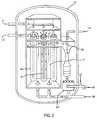
- FIG. 2illustrates an anode side start up heating according to one embodiment of the present invention.
- FIG. 3illustrates an example of indirect heating via a fuel burner.
- FIG. 4illustrates an example of an indirect heating via an electrical heater
- the present inventionprovides for an anode gas side heating during startup of a solid oxide fuel cell (SOFC) generator.
- SOFCsolid oxide fuel cell
- the start-up heaters of the prior artused hot air blown into the air feed tubes to heat the seal-less design SOFC generators. Unfortunately, this heats the generator very slowly since the thermal conductivity through the parts of the generator where the air comes into contact with are poor thermal conductors. Moreover, the air passes back over its own feed tube before being exhausted, which transfers a significant portion of the heat back to the used gas before it is exhausted.
- the present inventionheats the SOFC generator by circulating heated anode side gas.
- the anode gas flow pathis the fuel flow path.
- the major portion of the anode gas flowis recirculated spent fuel gas (about 3 ⁇ 4) with fresh fuel addition representing a minor portion. Therefore, when anode gas is heated prior to admission into the region containing fuel cells, it is quite easy to recirculate a large portion of the anode side gas using the existing ejector admitting air or some other gas as the primary fluid or a circulation pump in lieu of said ejector with the addition of make-up gas to compensate for that passing into the combustion zone and then exhausted at 12 .
- anode side heating of the SOFChas many advantages of the prior art cathode side air flow heating, and the two may be used in conjunction with one another.
- the gas on the anode side of the stackmay be heated in a variety of different ways. These are categorized as direct and indirect heating.
- the direct heatingindicates that a fuel burn is in direct contact with the gas flow, while with indirect heating the heat source has only thermal contact with the gas flow.
- the anode side of the generatoris made to handle fuel, adding a direct heating source can be accomplished without a large amount of modification.
- an addition to the systemis to add a burner. Although it does not necessarily have to produce flame, the burner will oxidize fuel with air to produce heat.
- the fuelcan be the normal hydrocarbon based SOFC fuel (e.g. natural gas).
- the fuelcan enter the system via its standard route, or a new fuel supply entrance can be positioned near the burner, as will be discussed.
- a direct heating sourceexposes the gas flow to the heating source, a portion of the fuel and by products will enter the stack and come into contact with metals such as nickel.
- nickelis at low (eg below 400° C.) temperatures, it is resistant to oxidization. Therefore, the anode gas at startup can be oxidizing without deleterious effect. This means that excess oxygen can be added to the burner to bring the generator to operating temperature more quickly.
- the stack temperatureexceeds about 400° C., metals such as nickel become susceptible to oxidization, which if allowed to occur is deleterious. Therefore, after the stack temperature reaches this point, the anode gas flow must be made chemically reducing.
- the anode gastypically contains a maximum of 5% hydrogen it will be chemically reducing without danger of flammability or explosion within the fuel cell stack.
- the fuel cell stack temperatureexceeds 600° C., the autoignition point for hydrogen in air, the hydrogen content of the anode gas can safely be increased.
- the anode gasmust be converted to start-up fuel with a higher hydrogen content, 40-50% hydrogen, and the fuel flow rate must be increased in proportion to the current extracted from the fuel cells until the stack achieves standard operating conditions consistent with the transition to normal fuel (e.g. natural gas).
- FIG. 2one embodiment of a direct burn using a single burner is shown.
- the heated air 2is channeled into capped fuel cells 6 via tubes 8 .
- the airthen passes back up the tubes, transferring heat along the cell until it enters the recuperator/combustion zone and is exhausted 12 .
- the heatpasses from the fuel cells 6 to the stack active/reformer area 17 . While the present invention also heats the reformer area 17 .
- the fuel used in the burnermay enter the system via the standard operating fuel pipe 14 , but in a particular embodiment the fuel enters 22 directly into the burner 24 which may also include an air flow source 26 .
- the gasAfter passing over the burner the gas is heated and combined with a supplemental gas flow 28 which primarily makes up for the gas that is not recirculated at 18 and lost to the exhaust 12 .
- the supplemental gas at 28can contain hydrogen so as to ensure a reducing environment for the fuel cells when required.
- the amount of the anode gas lost to the exhaustcan depend upon design details and the conditions, a loss of about 10-15% by volume can be expected for most embodiments.
- the burnermay use SOFC fuel to produce heat, but may then exhaust the gas rather than physically mix it with the anode gas flow.
- Thismay be a preferable embodiment where it is desired to control the heating of the anode gas distinctly from the chemistry.
- the redox considerations of the anode gaswarrant that certain mixtures of gas need to be maintained at different temperatures to achieve optimal heating with respect to reducing environments. To avoid this, indirect heating of the anode gas will allow separate and simpler control of the anode gas flow.
- FIG. 3illustrates an example of this where anode gas flow 30 passes over a thermal exchanger 31 within the burner 24 .
- the fuel 22 and air 26 that heat the burnerare then exhausted directly 32 rather than mixed with the anode gas flow 30 . Note that this exhaust may still contain useful heat and may be used, for example, to heat the cathode side air flow.
- an electric heater 34may be used.
- the start-up heating of the present inventionmay be used in conjunction with the air flow start-up heating of the prior art.
- the various direct and indirect heating embodiments of the present inventionmay be used in conjunction with each other as well. For example, a high oxygen direct heating fuel burn may take place when a generator is first being started up, but this will then be switched or tapered to an indirect heating as the temperatures increase.
- the present inventionprovides for an anode side gas flow heater for a fuel cell generator that comprises a recirculating anode gas flow, at least one burner, and an energy source.
- the energy sourceheats the burner, the anode gas flow passes over the burner and is heated, and the heated anode gas flow is then passed through the anode side of the fuel cell generator, where the fuel cell generator is heated.
- the burnerdirectly heats the recirculating anode gas flow
- the energy sourcemay be a fuel, such as the fuel for the fuel cell generator.
- the burnerhas multiple stages of burn which can increase the reducing properties of the anode gas flow. Multiple burners may be used, each of which has a burn characteristic that affects the reducing properties of the anode gas flow.
- the burnerindirectly heats the recirculating anode gas flow
- the energy sourceis a fuel.
- the fuelmay be fuel for the fuel cell generator, but may also be electrical.
- a plurality of burnersmay be present and at least one burner is directly heating and at least one burner is indirectly heating, and the directly heating burner is stopped from being used when temperatures within the fuel cell generator reach oxidizing conditions.
- approximately 10-15% of the recirculating anode gas flowis lost to exhaust.
- a supplemental gas flowmay be added to the recirculating anode gas flow to replace that lost to the exhaust.
- the supplemental gascontains approximately 5% hydrogen for the purpose of guaranteeing a reducing environment for the fuel cells.
- the fuel cell generatormay also be heated via a cathode side hot air flow. Exhaust from the burner may be used to heat the cathode side hot air flow.
- a solid oxide fuel cell generatorcomprises a recirculating anode side gas flow that passes over fuel cells in the generator, approximately 75-95% of the anode side gas flow is recirculated and the remaining portion is exhausted. Also there is at least one burner, the anode side gas flow passes over the burner prior to passing over the fuel cells, and a fuel source that enters the burner and mixes with an air flow and is burned by the burner producing heat that directly heats the anode side gas flow.
- a supplemental gas flow, the supplemental gas flow and the fuel source and the air flowequals the amount of anode side gas flow that is exhausted.
- the supplemental gas flowmay contain hydrogen to ensure a reducing bulk anode gas, and at least one of the burners may be adjusted when the generator reaches an oxidizing temperature to produce a more reducing anode side gas flow.
Landscapes
- Engineering & Computer Science (AREA)
- Chemical & Material Sciences (AREA)
- Life Sciences & Earth Sciences (AREA)
- Sustainable Development (AREA)
- Manufacturing & Machinery (AREA)
- Sustainable Energy (AREA)
- Chemical Kinetics & Catalysis (AREA)
- Electrochemistry (AREA)
- General Chemical & Material Sciences (AREA)
- Combustion & Propulsion (AREA)
- Fuel Cell (AREA)
- Resistance Heating (AREA)
Abstract
Description
Claims (7)
Priority Applications (8)
| Application Number | Priority Date | Filing Date | Title |
|---|---|---|---|
| US11/440,819US7951500B2 (en) | 2006-05-25 | 2006-05-25 | Anode gas stack start-up heater and purge gas generator |
| KR1020087029066AKR101496690B1 (en) | 2006-05-25 | 2006-11-30 | Anode gas stack start-up heater and purge gas generator |
| JP2009511999AJP2009538502A (en) | 2006-05-25 | 2006-11-30 | Stack start heater and purge gas generator with anode gas |
| CA2653046ACA2653046C (en) | 2006-05-25 | 2006-11-30 | Anode gas stack start-up heater and purge gas generator |
| AT06849908TATE459990T1 (en) | 2006-05-25 | 2006-11-30 | ANODE GAS STACK RUN-UP HEATER AND PUSH GAS GENERATOR |
| EP06849908AEP2027624B1 (en) | 2006-05-25 | 2006-11-30 | Anode gas stack start-up heater and purge gas generator |
| DE602006012744TDE602006012744D1 (en) | 2006-05-25 | 2006-11-30 | ANODENGAS STAPLE RISER HEATING ELEMENT AND RINSING GENERATOR |
| PCT/US2006/045838WO2007139583A1 (en) | 2006-05-25 | 2006-11-30 | Anode gas stack start-up heater and purge gas generator |
Applications Claiming Priority (1)
| Application Number | Priority Date | Filing Date | Title |
|---|---|---|---|
| US11/440,819US7951500B2 (en) | 2006-05-25 | 2006-05-25 | Anode gas stack start-up heater and purge gas generator |
Publications (2)
| Publication Number | Publication Date |
|---|---|
| US20070275282A1 US20070275282A1 (en) | 2007-11-29 |
| US7951500B2true US7951500B2 (en) | 2011-05-31 |
Family
ID=38529412
Family Applications (1)
| Application Number | Title | Priority Date | Filing Date |
|---|---|---|---|
| US11/440,819Expired - Fee RelatedUS7951500B2 (en) | 2006-05-25 | 2006-05-25 | Anode gas stack start-up heater and purge gas generator |
Country Status (8)
| Country | Link |
|---|---|
| US (1) | US7951500B2 (en) |
| EP (1) | EP2027624B1 (en) |
| JP (1) | JP2009538502A (en) |
| KR (1) | KR101496690B1 (en) |
| AT (1) | ATE459990T1 (en) |
| CA (1) | CA2653046C (en) |
| DE (1) | DE602006012744D1 (en) |
| WO (1) | WO2007139583A1 (en) |
Cited By (1)
| Publication number | Priority date | Publication date | Assignee | Title |
|---|---|---|---|---|
| US9222410B2 (en) | 2011-04-13 | 2015-12-29 | General Electric Company | Power plant |
Families Citing this family (10)
| Publication number | Priority date | Publication date | Assignee | Title |
|---|---|---|---|---|
| DE102004059494C5 (en)* | 2004-12-10 | 2008-07-24 | Baxi Innotech Gmbh | Method for determining an air ratio in a burner for a fuel cell heater and fuel cell heater |
| FI122476B (en)* | 2008-07-10 | 2012-02-15 | Waertsilae Finland Oy | Process and arrangement for reducing the consumption of shielding gas in a fuel cell system |
| FI120949B (en)* | 2008-07-10 | 2010-05-14 | Waertsilae Finland Oy | Method and arrangement for enhancing the preheating of the fuel cell system |
| GB2475495B (en)* | 2009-11-19 | 2011-10-12 | Alstom Technology Ltd | Fuel cell system and operating method |
| DE102010001260A1 (en) | 2010-01-27 | 2011-07-28 | Robert Bosch GmbH, 70469 | Fuel cell system with improved fuel gas circulation |
| US9620792B2 (en) | 2011-01-03 | 2017-04-11 | Audi Ag | Thermal energy recycling fuel cell arrangement |
| KR101223645B1 (en)* | 2011-03-28 | 2013-01-17 | 부산대학교 산학협력단 | Solid oxide fuel cell system fueled by natural gas |
| JP6090419B1 (en)* | 2015-12-22 | 2017-03-08 | 富士電機株式会社 | Fuel cell device |
| DE102021106295A1 (en) | 2021-03-16 | 2022-09-22 | Audi Aktiengesellschaft | Method of starting a solid oxide fuel cell device, solid oxide fuel cell device, and fuel cell vehicle |
| WO2024241387A1 (en)* | 2023-05-19 | 2024-11-28 | 日産自動車株式会社 | Control method for fuel cell system and control device for fuel cell system |
Citations (8)
| Publication number | Priority date | Publication date | Assignee | Title |
|---|---|---|---|---|
| EP0948070A1 (en) | 1998-02-17 | 1999-10-06 | Mitsubishi Heavy Industries, Ltd. | Solid electrolyte fuel cell power generating system |
| US20010014415A1 (en)* | 2000-02-16 | 2001-08-16 | Nissan Motor Co., Ltd. | Fuel cell system and method |
| DE10149014A1 (en) | 2001-09-28 | 2003-04-17 | Iav Gmbh | High temperature fuel cell system has oxide ceramic high temperature fuel cell whose residual anode gases are burnt in porous burner arranged after fuel cell. |
| US20040146763A1 (en)* | 2003-01-27 | 2004-07-29 | Pondo Joseph M. | Thermally integrated fuel cell power system |
| US20050084388A1 (en)* | 2003-07-17 | 2005-04-21 | Hayes Alan E. | Positive displacement liquid pump |
| US20050123808A1 (en)* | 2003-12-05 | 2005-06-09 | Siemens Westinghouse Power Corporation | Integral air preheater and start-up heating means for solid oxide fuel cell power generators |
| US20060093879A1 (en) | 2001-01-25 | 2006-05-04 | Deliang Yang | Procedure for starting up a fuel cell system having an anode exhaust recycle loop |
| US7276096B2 (en)* | 2003-06-27 | 2007-10-02 | Ultracell Corporation | Fuel processor dewar and methods |
Family Cites Families (9)
| Publication number | Priority date | Publication date | Assignee | Title |
|---|---|---|---|---|
| JPH01124962A (en)* | 1987-11-10 | 1989-05-17 | Fuji Electric Co Ltd | Alkaline electrolyte fuel cell device |
| JPH09293525A (en)* | 1996-04-30 | 1997-11-11 | Mitsubishi Heavy Ind Ltd | Solid electrolyte fuel cell power generation system |
| JP3989604B2 (en)* | 1997-12-02 | 2007-10-10 | 東京瓦斯株式会社 | Method for starting and stopping a solid electrolyte fuel cell |
| JP4519221B2 (en)* | 1999-07-13 | 2010-08-04 | 中部電力株式会社 | Solid oxide fuel cell |
| JP2001052727A (en)* | 1999-08-04 | 2001-02-23 | Mitsubishi Heavy Ind Ltd | Power generating system by fuel cell |
| JP3913008B2 (en)* | 2001-06-28 | 2007-05-09 | 三菱重工業株式会社 | Solid oxide fuel cell system |
| US6764784B2 (en) | 2001-09-17 | 2004-07-20 | Siemens Westinghouse Power Corporation | Standard package design for both atmospheric and pressurized SOFC power generation system |
| KR20040011289A (en)* | 2002-07-30 | 2004-02-05 | 엘지전자 주식회사 | Device for heating fuel/air of fuel cell |
| JP4654567B2 (en)* | 2003-05-01 | 2011-03-23 | 三菱マテリアル株式会社 | Solid oxide fuel cell and method of operating the same |
- 2006
- 2006-05-25USUS11/440,819patent/US7951500B2/ennot_activeExpired - Fee Related
- 2006-11-30WOPCT/US2006/045838patent/WO2007139583A1/enactiveApplication Filing
- 2006-11-30EPEP06849908Apatent/EP2027624B1/ennot_activeNot-in-force
- 2006-11-30KRKR1020087029066Apatent/KR101496690B1/ennot_activeExpired - Fee Related
- 2006-11-30DEDE602006012744Tpatent/DE602006012744D1/enactiveActive
- 2006-11-30ATAT06849908Tpatent/ATE459990T1/ennot_activeIP Right Cessation
- 2006-11-30JPJP2009511999Apatent/JP2009538502A/enactivePending
- 2006-11-30CACA2653046Apatent/CA2653046C/ennot_activeExpired - Fee Related
Patent Citations (8)
| Publication number | Priority date | Publication date | Assignee | Title |
|---|---|---|---|---|
| EP0948070A1 (en) | 1998-02-17 | 1999-10-06 | Mitsubishi Heavy Industries, Ltd. | Solid electrolyte fuel cell power generating system |
| US20010014415A1 (en)* | 2000-02-16 | 2001-08-16 | Nissan Motor Co., Ltd. | Fuel cell system and method |
| US20060093879A1 (en) | 2001-01-25 | 2006-05-04 | Deliang Yang | Procedure for starting up a fuel cell system having an anode exhaust recycle loop |
| DE10149014A1 (en) | 2001-09-28 | 2003-04-17 | Iav Gmbh | High temperature fuel cell system has oxide ceramic high temperature fuel cell whose residual anode gases are burnt in porous burner arranged after fuel cell. |
| US20040146763A1 (en)* | 2003-01-27 | 2004-07-29 | Pondo Joseph M. | Thermally integrated fuel cell power system |
| US7276096B2 (en)* | 2003-06-27 | 2007-10-02 | Ultracell Corporation | Fuel processor dewar and methods |
| US20050084388A1 (en)* | 2003-07-17 | 2005-04-21 | Hayes Alan E. | Positive displacement liquid pump |
| US20050123808A1 (en)* | 2003-12-05 | 2005-06-09 | Siemens Westinghouse Power Corporation | Integral air preheater and start-up heating means for solid oxide fuel cell power generators |
Cited By (1)
| Publication number | Priority date | Publication date | Assignee | Title |
|---|---|---|---|---|
| US9222410B2 (en) | 2011-04-13 | 2015-12-29 | General Electric Company | Power plant |
Also Published As
| Publication number | Publication date |
|---|---|
| EP2027624B1 (en) | 2010-03-03 |
| ATE459990T1 (en) | 2010-03-15 |
| KR20090014179A (en) | 2009-02-06 |
| CA2653046A1 (en) | 2007-12-06 |
| CA2653046C (en) | 2013-12-31 |
| DE602006012744D1 (en) | 2010-04-15 |
| JP2009538502A (en) | 2009-11-05 |
| WO2007139583A1 (en) | 2007-12-06 |
| KR101496690B1 (en) | 2015-03-02 |
| EP2027624A1 (en) | 2009-02-25 |
| US20070275282A1 (en) | 2007-11-29 |
Similar Documents
| Publication | Publication Date | Title |
|---|---|---|
| US7951500B2 (en) | Anode gas stack start-up heater and purge gas generator | |
| US8202656B2 (en) | Thermally integrated fuel cell system | |
| JP2001052727A (en) | Power generating system by fuel cell | |
| US10727510B2 (en) | Method of starting-up a fuel cell arrangement and fuel cell arrangement | |
| CN109964351B (en) | Integrated fuel cell block with modified fuel cell cycle for integrated reforming fuel cell | |
| JP2022507791A (en) | Fuel cell system, its use and method of operation | |
| CN117673403A (en) | Fuel cell system and start control method applied to fuel cell system | |
| JP2008234994A (en) | Fuel cell system | |
| JPWO2003038934A1 (en) | Fuel cell system | |
| JP2889807B2 (en) | Fuel cell system | |
| KR20190077051A (en) | Improved fuel cell cycle for block-fuel-cell reforming | |
| JP4342172B2 (en) | Co-energy system | |
| CN100533833C (en) | Apparatus and methods within a fuel cell device | |
| US8221928B2 (en) | Preheating arrangement in a fuel cell apparatus | |
| JP2003059519A (en) | Fuel cell system and cogeneration system | |
| JP2003132903A (en) | Combined system between industrial furnace and solid oxide fuel cell | |
| JP5000867B2 (en) | Fuel cell power generation system | |
| US9461328B1 (en) | Solid oxide fuel cell power plant having a bootstrap start-up system | |
| KR102695335B1 (en) | Direct hydrogen fuel cell system | |
| US20040241513A1 (en) | Integrated recupreator and burner for fuel cells | |
| JP5498552B2 (en) | Fuel cell system | |
| US10333160B2 (en) | Integrated fuel cell block with a revised fuel cell cycle for in block reforming fuel cells | |
| CN120345083A (en) | Fuel cell system and method | |
| WO2022215224A1 (en) | Fuel cell system | |
| CN120280522A (en) | SOFC system with high-temperature anode tail gas circulation and operation method |
Legal Events
| Date | Code | Title | Description |
|---|---|---|---|
| AS | Assignment | Owner name:SIEMENS POWER GENERATION, INC., FLORIDA Free format text:ASSIGNMENT OF ASSIGNORS INTEREST;ASSIGNORS:VEYO, STEPHEN E.;GEORGE, RAYMOND A.;REEL/FRAME:017932/0433 Effective date:20060523 | |
| AS | Assignment | Owner name:SIEMENS ENERGY, INC., FLORIDA Free format text:CHANGE OF NAME;ASSIGNOR:SIEMENS POWER GENERATION, INC.;REEL/FRAME:022488/0630 Effective date:20081001 Owner name:SIEMENS ENERGY, INC.,FLORIDA Free format text:CHANGE OF NAME;ASSIGNOR:SIEMENS POWER GENERATION, INC.;REEL/FRAME:022488/0630 Effective date:20081001 | |
| AS | Assignment | Owner name:U.S. DEPARTMENT OF ENERGY, DISTRICT OF COLUMBIA Free format text:CONFIRMATORY LICENSE;ASSIGNOR:SIMENS ENERGY, INC.;REEL/FRAME:025935/0072 Effective date:20100322 | |
| STCF | Information on status: patent grant | Free format text:PATENTED CASE | |
| FPAY | Fee payment | Year of fee payment:4 | |
| FEPP | Fee payment procedure | Free format text:MAINTENANCE FEE REMINDER MAILED (ORIGINAL EVENT CODE: REM.); ENTITY STATUS OF PATENT OWNER: LARGE ENTITY | |
| LAPS | Lapse for failure to pay maintenance fees | Free format text:PATENT EXPIRED FOR FAILURE TO PAY MAINTENANCE FEES (ORIGINAL EVENT CODE: EXP.); ENTITY STATUS OF PATENT OWNER: LARGE ENTITY | |
| STCH | Information on status: patent discontinuation | Free format text:PATENT EXPIRED DUE TO NONPAYMENT OF MAINTENANCE FEES UNDER 37 CFR 1.362 | |
| FP | Lapsed due to failure to pay maintenance fee | Effective date:20190531 |