US7951204B2 - Knee prosthesis with a rotational plate - Google Patents
Knee prosthesis with a rotational plateDownload PDFInfo
- Publication number
- US7951204B2 US7951204B2US11/143,742US14374205AUS7951204B2US 7951204 B2US7951204 B2US 7951204B2US 14374205 AUS14374205 AUS 14374205AUS 7951204 B2US7951204 B2US 7951204B2
- Authority
- US
- United States
- Prior art keywords
- base
- plate
- upstand
- rotation
- tibia
- Prior art date
- Legal status (The legal status is an assumption and is not a legal conclusion. Google has not performed a legal analysis and makes no representation as to the accuracy of the status listed.)
- Expired - Fee Related, expires
Links
- 210000003127kneeAnatomy0.000titleclaimsabstractdescription76
- 210000002303tibiaAnatomy0.000claimsabstractdescription116
- 239000002184metalSubstances0.000claimsabstractdescription88
- 229910052751metalInorganic materials0.000claimsabstractdescription88
- 238000004873anchoringMethods0.000claimsdescription17
- 230000002093peripheral effectEffects0.000claimsdescription16
- 210000002967posterior cruciate ligamentAnatomy0.000claimsdescription8
- 210000000988bone and boneAnatomy0.000claims2
- 238000000034methodMethods0.000claims2
- 238000002513implantationMethods0.000claims1
- 230000000694effectsEffects0.000description1
- 239000000463materialSubstances0.000description1
- 230000000284resting effectEffects0.000description1
Images


Classifications
- A—HUMAN NECESSITIES
- A61—MEDICAL OR VETERINARY SCIENCE; HYGIENE
- A61F—FILTERS IMPLANTABLE INTO BLOOD VESSELS; PROSTHESES; DEVICES PROVIDING PATENCY TO, OR PREVENTING COLLAPSING OF, TUBULAR STRUCTURES OF THE BODY, e.g. STENTS; ORTHOPAEDIC, NURSING OR CONTRACEPTIVE DEVICES; FOMENTATION; TREATMENT OR PROTECTION OF EYES OR EARS; BANDAGES, DRESSINGS OR ABSORBENT PADS; FIRST-AID KITS
- A61F2/00—Filters implantable into blood vessels; Prostheses, i.e. artificial substitutes or replacements for parts of the body; Appliances for connecting them with the body; Devices providing patency to, or preventing collapsing of, tubular structures of the body, e.g. stents
- A61F2/02—Prostheses implantable into the body
- A61F2/30—Joints
- A61F2/38—Joints for elbows or knees
- A61F2/3868—Joints for elbows or knees with sliding tibial bearing
- A—HUMAN NECESSITIES
- A61—MEDICAL OR VETERINARY SCIENCE; HYGIENE
- A61F—FILTERS IMPLANTABLE INTO BLOOD VESSELS; PROSTHESES; DEVICES PROVIDING PATENCY TO, OR PREVENTING COLLAPSING OF, TUBULAR STRUCTURES OF THE BODY, e.g. STENTS; ORTHOPAEDIC, NURSING OR CONTRACEPTIVE DEVICES; FOMENTATION; TREATMENT OR PROTECTION OF EYES OR EARS; BANDAGES, DRESSINGS OR ABSORBENT PADS; FIRST-AID KITS
- A61F2/00—Filters implantable into blood vessels; Prostheses, i.e. artificial substitutes or replacements for parts of the body; Appliances for connecting them with the body; Devices providing patency to, or preventing collapsing of, tubular structures of the body, e.g. stents
- A61F2/02—Prostheses implantable into the body
- A61F2/30—Joints
- A61F2/38—Joints for elbows or knees
- A61F2/389—Tibial components
- A—HUMAN NECESSITIES
- A61—MEDICAL OR VETERINARY SCIENCE; HYGIENE
- A61F—FILTERS IMPLANTABLE INTO BLOOD VESSELS; PROSTHESES; DEVICES PROVIDING PATENCY TO, OR PREVENTING COLLAPSING OF, TUBULAR STRUCTURES OF THE BODY, e.g. STENTS; ORTHOPAEDIC, NURSING OR CONTRACEPTIVE DEVICES; FOMENTATION; TREATMENT OR PROTECTION OF EYES OR EARS; BANDAGES, DRESSINGS OR ABSORBENT PADS; FIRST-AID KITS
- A61F2/00—Filters implantable into blood vessels; Prostheses, i.e. artificial substitutes or replacements for parts of the body; Appliances for connecting them with the body; Devices providing patency to, or preventing collapsing of, tubular structures of the body, e.g. stents
- A61F2/02—Prostheses implantable into the body
- A61F2/30—Joints
- A61F2002/30001—Additional features of subject-matter classified in A61F2/28, A61F2/30 and subgroups thereof
- A61F2002/30108—Shapes
- A61F2002/3011—Cross-sections or two-dimensional shapes
- A61F2002/30112—Rounded shapes, e.g. with rounded corners
- A61F2002/30125—Rounded shapes, e.g. with rounded corners elliptical or oval
- A—HUMAN NECESSITIES
- A61—MEDICAL OR VETERINARY SCIENCE; HYGIENE
- A61F—FILTERS IMPLANTABLE INTO BLOOD VESSELS; PROSTHESES; DEVICES PROVIDING PATENCY TO, OR PREVENTING COLLAPSING OF, TUBULAR STRUCTURES OF THE BODY, e.g. STENTS; ORTHOPAEDIC, NURSING OR CONTRACEPTIVE DEVICES; FOMENTATION; TREATMENT OR PROTECTION OF EYES OR EARS; BANDAGES, DRESSINGS OR ABSORBENT PADS; FIRST-AID KITS
- A61F2/00—Filters implantable into blood vessels; Prostheses, i.e. artificial substitutes or replacements for parts of the body; Appliances for connecting them with the body; Devices providing patency to, or preventing collapsing of, tubular structures of the body, e.g. stents
- A61F2/02—Prostheses implantable into the body
- A61F2/30—Joints
- A61F2002/30001—Additional features of subject-matter classified in A61F2/28, A61F2/30 and subgroups thereof
- A61F2002/30108—Shapes
- A61F2002/3011—Cross-sections or two-dimensional shapes
- A61F2002/30112—Rounded shapes, e.g. with rounded corners
- A61F2002/30133—Rounded shapes, e.g. with rounded corners kidney-shaped or bean-shaped
- A—HUMAN NECESSITIES
- A61—MEDICAL OR VETERINARY SCIENCE; HYGIENE
- A61F—FILTERS IMPLANTABLE INTO BLOOD VESSELS; PROSTHESES; DEVICES PROVIDING PATENCY TO, OR PREVENTING COLLAPSING OF, TUBULAR STRUCTURES OF THE BODY, e.g. STENTS; ORTHOPAEDIC, NURSING OR CONTRACEPTIVE DEVICES; FOMENTATION; TREATMENT OR PROTECTION OF EYES OR EARS; BANDAGES, DRESSINGS OR ABSORBENT PADS; FIRST-AID KITS
- A61F2/00—Filters implantable into blood vessels; Prostheses, i.e. artificial substitutes or replacements for parts of the body; Appliances for connecting them with the body; Devices providing patency to, or preventing collapsing of, tubular structures of the body, e.g. stents
- A61F2/02—Prostheses implantable into the body
- A61F2/30—Joints
- A61F2002/30001—Additional features of subject-matter classified in A61F2/28, A61F2/30 and subgroups thereof
- A61F2002/30108—Shapes
- A61F2002/3011—Cross-sections or two-dimensional shapes
- A61F2002/30138—Convex polygonal shapes
- A61F2002/30153—Convex polygonal shapes rectangular
- A—HUMAN NECESSITIES
- A61—MEDICAL OR VETERINARY SCIENCE; HYGIENE
- A61F—FILTERS IMPLANTABLE INTO BLOOD VESSELS; PROSTHESES; DEVICES PROVIDING PATENCY TO, OR PREVENTING COLLAPSING OF, TUBULAR STRUCTURES OF THE BODY, e.g. STENTS; ORTHOPAEDIC, NURSING OR CONTRACEPTIVE DEVICES; FOMENTATION; TREATMENT OR PROTECTION OF EYES OR EARS; BANDAGES, DRESSINGS OR ABSORBENT PADS; FIRST-AID KITS
- A61F2/00—Filters implantable into blood vessels; Prostheses, i.e. artificial substitutes or replacements for parts of the body; Appliances for connecting them with the body; Devices providing patency to, or preventing collapsing of, tubular structures of the body, e.g. stents
- A61F2/02—Prostheses implantable into the body
- A61F2/30—Joints
- A61F2002/30001—Additional features of subject-matter classified in A61F2/28, A61F2/30 and subgroups thereof
- A61F2002/30316—The prosthesis having different structural features at different locations within the same prosthesis; Connections between prosthetic parts; Special structural features of bone or joint prostheses not otherwise provided for
- A61F2002/30329—Connections or couplings between prosthetic parts, e.g. between modular parts; Connecting elements
- A61F2002/30331—Connections or couplings between prosthetic parts, e.g. between modular parts; Connecting elements made by longitudinally pushing a protrusion into a complementarily-shaped recess, e.g. held by friction fit
- A61F2002/30362—Connections or couplings between prosthetic parts, e.g. between modular parts; Connecting elements made by longitudinally pushing a protrusion into a complementarily-shaped recess, e.g. held by friction fit with possibility of relative movement between the protrusion and the recess
- A61F2002/30364—Rotation about the common longitudinal axis
- A61F2002/30365—Rotation about the common longitudinal axis with additional means for limiting said rotation
- A—HUMAN NECESSITIES
- A61—MEDICAL OR VETERINARY SCIENCE; HYGIENE
- A61F—FILTERS IMPLANTABLE INTO BLOOD VESSELS; PROSTHESES; DEVICES PROVIDING PATENCY TO, OR PREVENTING COLLAPSING OF, TUBULAR STRUCTURES OF THE BODY, e.g. STENTS; ORTHOPAEDIC, NURSING OR CONTRACEPTIVE DEVICES; FOMENTATION; TREATMENT OR PROTECTION OF EYES OR EARS; BANDAGES, DRESSINGS OR ABSORBENT PADS; FIRST-AID KITS
- A61F2/00—Filters implantable into blood vessels; Prostheses, i.e. artificial substitutes or replacements for parts of the body; Appliances for connecting them with the body; Devices providing patency to, or preventing collapsing of, tubular structures of the body, e.g. stents
- A61F2/02—Prostheses implantable into the body
- A61F2/30—Joints
- A61F2002/30001—Additional features of subject-matter classified in A61F2/28, A61F2/30 and subgroups thereof
- A61F2002/30316—The prosthesis having different structural features at different locations within the same prosthesis; Connections between prosthetic parts; Special structural features of bone or joint prostheses not otherwise provided for
- A61F2002/30329—Connections or couplings between prosthetic parts, e.g. between modular parts; Connecting elements
- A61F2002/30383—Connections or couplings between prosthetic parts, e.g. between modular parts; Connecting elements made by laterally inserting a protrusion, e.g. a rib into a complementarily-shaped groove
- A61F2002/30403—Longitudinally-oriented cooperating ribs and grooves on mating lateral surfaces of a mainly longitudinal connection
- A—HUMAN NECESSITIES
- A61—MEDICAL OR VETERINARY SCIENCE; HYGIENE
- A61F—FILTERS IMPLANTABLE INTO BLOOD VESSELS; PROSTHESES; DEVICES PROVIDING PATENCY TO, OR PREVENTING COLLAPSING OF, TUBULAR STRUCTURES OF THE BODY, e.g. STENTS; ORTHOPAEDIC, NURSING OR CONTRACEPTIVE DEVICES; FOMENTATION; TREATMENT OR PROTECTION OF EYES OR EARS; BANDAGES, DRESSINGS OR ABSORBENT PADS; FIRST-AID KITS
- A61F2/00—Filters implantable into blood vessels; Prostheses, i.e. artificial substitutes or replacements for parts of the body; Appliances for connecting them with the body; Devices providing patency to, or preventing collapsing of, tubular structures of the body, e.g. stents
- A61F2/02—Prostheses implantable into the body
- A61F2/30—Joints
- A61F2002/30001—Additional features of subject-matter classified in A61F2/28, A61F2/30 and subgroups thereof
- A61F2002/30316—The prosthesis having different structural features at different locations within the same prosthesis; Connections between prosthetic parts; Special structural features of bone or joint prostheses not otherwise provided for
- A61F2002/30329—Connections or couplings between prosthetic parts, e.g. between modular parts; Connecting elements
- A61F2002/30476—Connections or couplings between prosthetic parts, e.g. between modular parts; Connecting elements locked by an additional locking mechanism
- A61F2002/305—Snap connection
- A—HUMAN NECESSITIES
- A61—MEDICAL OR VETERINARY SCIENCE; HYGIENE
- A61F—FILTERS IMPLANTABLE INTO BLOOD VESSELS; PROSTHESES; DEVICES PROVIDING PATENCY TO, OR PREVENTING COLLAPSING OF, TUBULAR STRUCTURES OF THE BODY, e.g. STENTS; ORTHOPAEDIC, NURSING OR CONTRACEPTIVE DEVICES; FOMENTATION; TREATMENT OR PROTECTION OF EYES OR EARS; BANDAGES, DRESSINGS OR ABSORBENT PADS; FIRST-AID KITS
- A61F2/00—Filters implantable into blood vessels; Prostheses, i.e. artificial substitutes or replacements for parts of the body; Appliances for connecting them with the body; Devices providing patency to, or preventing collapsing of, tubular structures of the body, e.g. stents
- A61F2/02—Prostheses implantable into the body
- A61F2/30—Joints
- A61F2002/30001—Additional features of subject-matter classified in A61F2/28, A61F2/30 and subgroups thereof
- A61F2002/30316—The prosthesis having different structural features at different locations within the same prosthesis; Connections between prosthetic parts; Special structural features of bone or joint prostheses not otherwise provided for
- A61F2002/30535—Special structural features of bone or joint prostheses not otherwise provided for
- A—HUMAN NECESSITIES
- A61—MEDICAL OR VETERINARY SCIENCE; HYGIENE
- A61F—FILTERS IMPLANTABLE INTO BLOOD VESSELS; PROSTHESES; DEVICES PROVIDING PATENCY TO, OR PREVENTING COLLAPSING OF, TUBULAR STRUCTURES OF THE BODY, e.g. STENTS; ORTHOPAEDIC, NURSING OR CONTRACEPTIVE DEVICES; FOMENTATION; TREATMENT OR PROTECTION OF EYES OR EARS; BANDAGES, DRESSINGS OR ABSORBENT PADS; FIRST-AID KITS
- A61F2/00—Filters implantable into blood vessels; Prostheses, i.e. artificial substitutes or replacements for parts of the body; Appliances for connecting them with the body; Devices providing patency to, or preventing collapsing of, tubular structures of the body, e.g. stents
- A61F2/02—Prostheses implantable into the body
- A61F2/30—Joints
- A61F2002/30001—Additional features of subject-matter classified in A61F2/28, A61F2/30 and subgroups thereof
- A61F2002/30667—Features concerning an interaction with the environment or a particular use of the prosthesis
- A61F2002/30688—Means for allowing passage or sliding of tendons or ligaments
- A—HUMAN NECESSITIES
- A61—MEDICAL OR VETERINARY SCIENCE; HYGIENE
- A61F—FILTERS IMPLANTABLE INTO BLOOD VESSELS; PROSTHESES; DEVICES PROVIDING PATENCY TO, OR PREVENTING COLLAPSING OF, TUBULAR STRUCTURES OF THE BODY, e.g. STENTS; ORTHOPAEDIC, NURSING OR CONTRACEPTIVE DEVICES; FOMENTATION; TREATMENT OR PROTECTION OF EYES OR EARS; BANDAGES, DRESSINGS OR ABSORBENT PADS; FIRST-AID KITS
- A61F2/00—Filters implantable into blood vessels; Prostheses, i.e. artificial substitutes or replacements for parts of the body; Appliances for connecting them with the body; Devices providing patency to, or preventing collapsing of, tubular structures of the body, e.g. stents
- A61F2/02—Prostheses implantable into the body
- A61F2/30—Joints
- A61F2/30767—Special external or bone-contacting surface, e.g. coating for improving bone ingrowth
- A61F2/30771—Special external or bone-contacting surface, e.g. coating for improving bone ingrowth applied in original prostheses, e.g. holes or grooves
- A61F2002/3082—Grooves
- A—HUMAN NECESSITIES
- A61—MEDICAL OR VETERINARY SCIENCE; HYGIENE
- A61F—FILTERS IMPLANTABLE INTO BLOOD VESSELS; PROSTHESES; DEVICES PROVIDING PATENCY TO, OR PREVENTING COLLAPSING OF, TUBULAR STRUCTURES OF THE BODY, e.g. STENTS; ORTHOPAEDIC, NURSING OR CONTRACEPTIVE DEVICES; FOMENTATION; TREATMENT OR PROTECTION OF EYES OR EARS; BANDAGES, DRESSINGS OR ABSORBENT PADS; FIRST-AID KITS
- A61F2/00—Filters implantable into blood vessels; Prostheses, i.e. artificial substitutes or replacements for parts of the body; Appliances for connecting them with the body; Devices providing patency to, or preventing collapsing of, tubular structures of the body, e.g. stents
- A61F2/02—Prostheses implantable into the body
- A61F2/30—Joints
- A61F2/30767—Special external or bone-contacting surface, e.g. coating for improving bone ingrowth
- A61F2/30771—Special external or bone-contacting surface, e.g. coating for improving bone ingrowth applied in original prostheses, e.g. holes or grooves
- A61F2002/30878—Special external or bone-contacting surface, e.g. coating for improving bone ingrowth applied in original prostheses, e.g. holes or grooves with non-sharp protrusions, for instance contacting the bone for anchoring, e.g. keels, pegs, pins, posts, shanks, stems, struts
- A—HUMAN NECESSITIES
- A61—MEDICAL OR VETERINARY SCIENCE; HYGIENE
- A61F—FILTERS IMPLANTABLE INTO BLOOD VESSELS; PROSTHESES; DEVICES PROVIDING PATENCY TO, OR PREVENTING COLLAPSING OF, TUBULAR STRUCTURES OF THE BODY, e.g. STENTS; ORTHOPAEDIC, NURSING OR CONTRACEPTIVE DEVICES; FOMENTATION; TREATMENT OR PROTECTION OF EYES OR EARS; BANDAGES, DRESSINGS OR ABSORBENT PADS; FIRST-AID KITS
- A61F2220/00—Fixations or connections for prostheses classified in groups A61F2/00 - A61F2/26 or A61F2/82 or A61F9/00 or A61F11/00 or subgroups thereof
- A61F2220/0025—Connections or couplings between prosthetic parts, e.g. between modular parts; Connecting elements
- A61F2220/0033—Connections or couplings between prosthetic parts, e.g. between modular parts; Connecting elements made by longitudinally pushing a protrusion into a complementary-shaped recess, e.g. held by friction fit
- A—HUMAN NECESSITIES
- A61—MEDICAL OR VETERINARY SCIENCE; HYGIENE
- A61F—FILTERS IMPLANTABLE INTO BLOOD VESSELS; PROSTHESES; DEVICES PROVIDING PATENCY TO, OR PREVENTING COLLAPSING OF, TUBULAR STRUCTURES OF THE BODY, e.g. STENTS; ORTHOPAEDIC, NURSING OR CONTRACEPTIVE DEVICES; FOMENTATION; TREATMENT OR PROTECTION OF EYES OR EARS; BANDAGES, DRESSINGS OR ABSORBENT PADS; FIRST-AID KITS
- A61F2230/00—Geometry of prostheses classified in groups A61F2/00 - A61F2/26 or A61F2/82 or A61F9/00 or A61F11/00 or subgroups thereof
- A61F2230/0002—Two-dimensional shapes, e.g. cross-sections
- A61F2230/0004—Rounded shapes, e.g. with rounded corners
- A61F2230/0008—Rounded shapes, e.g. with rounded corners elliptical or oval
- A—HUMAN NECESSITIES
- A61—MEDICAL OR VETERINARY SCIENCE; HYGIENE
- A61F—FILTERS IMPLANTABLE INTO BLOOD VESSELS; PROSTHESES; DEVICES PROVIDING PATENCY TO, OR PREVENTING COLLAPSING OF, TUBULAR STRUCTURES OF THE BODY, e.g. STENTS; ORTHOPAEDIC, NURSING OR CONTRACEPTIVE DEVICES; FOMENTATION; TREATMENT OR PROTECTION OF EYES OR EARS; BANDAGES, DRESSINGS OR ABSORBENT PADS; FIRST-AID KITS
- A61F2230/00—Geometry of prostheses classified in groups A61F2/00 - A61F2/26 or A61F2/82 or A61F9/00 or A61F11/00 or subgroups thereof
- A61F2230/0002—Two-dimensional shapes, e.g. cross-sections
- A61F2230/0004—Rounded shapes, e.g. with rounded corners
- A61F2230/0015—Kidney-shaped, e.g. bean-shaped
- A—HUMAN NECESSITIES
- A61—MEDICAL OR VETERINARY SCIENCE; HYGIENE
- A61F—FILTERS IMPLANTABLE INTO BLOOD VESSELS; PROSTHESES; DEVICES PROVIDING PATENCY TO, OR PREVENTING COLLAPSING OF, TUBULAR STRUCTURES OF THE BODY, e.g. STENTS; ORTHOPAEDIC, NURSING OR CONTRACEPTIVE DEVICES; FOMENTATION; TREATMENT OR PROTECTION OF EYES OR EARS; BANDAGES, DRESSINGS OR ABSORBENT PADS; FIRST-AID KITS
- A61F2230/00—Geometry of prostheses classified in groups A61F2/00 - A61F2/26 or A61F2/82 or A61F9/00 or A61F11/00 or subgroups thereof
- A61F2230/0002—Two-dimensional shapes, e.g. cross-sections
- A61F2230/0017—Angular shapes
- A61F2230/0019—Angular shapes rectangular
- A—HUMAN NECESSITIES
- A61—MEDICAL OR VETERINARY SCIENCE; HYGIENE
- A61F—FILTERS IMPLANTABLE INTO BLOOD VESSELS; PROSTHESES; DEVICES PROVIDING PATENCY TO, OR PREVENTING COLLAPSING OF, TUBULAR STRUCTURES OF THE BODY, e.g. STENTS; ORTHOPAEDIC, NURSING OR CONTRACEPTIVE DEVICES; FOMENTATION; TREATMENT OR PROTECTION OF EYES OR EARS; BANDAGES, DRESSINGS OR ABSORBENT PADS; FIRST-AID KITS
- A61F2250/00—Special features of prostheses classified in groups A61F2/00 - A61F2/26 or A61F2/82 or A61F9/00 or A61F11/00 or subgroups thereof
- A61F2250/0058—Additional features; Implant or prostheses properties not otherwise provided for
- A—HUMAN NECESSITIES
- A61—MEDICAL OR VETERINARY SCIENCE; HYGIENE
- A61F—FILTERS IMPLANTABLE INTO BLOOD VESSELS; PROSTHESES; DEVICES PROVIDING PATENCY TO, OR PREVENTING COLLAPSING OF, TUBULAR STRUCTURES OF THE BODY, e.g. STENTS; ORTHOPAEDIC, NURSING OR CONTRACEPTIVE DEVICES; FOMENTATION; TREATMENT OR PROTECTION OF EYES OR EARS; BANDAGES, DRESSINGS OR ABSORBENT PADS; FIRST-AID KITS
- A61F2310/00—Prostheses classified in A61F2/28 or A61F2/30 - A61F2/44 being constructed from or coated with a particular material
- A61F2310/00005—The prosthesis being constructed from a particular material
- A61F2310/00011—Metals or alloys
Definitions
- the present inventionrelates to a knee prosthesis and more specifically to the device for assembling its tibia plate, which is made of plastic, on its metal base anchored beforehand into the tibia bone tissue.
- Knee prostheseswhich comprise a plastic tibia part which is free to rotate about the tibia bone axis with respect to the metal base secured to the tibia are known.
- This freedom of rotationis generally achieved via a male shaft integral with the plastic tibia part which engages with a bore made in the metal base.
- this freedom of rotationmay be achieved by a male shaft secured to the metal base which engages with a bore made in the plastic tibia part.
- the center of rotationis necessarily positioned at a point of the device or [sic] the bore can be made, that is to say in a part or [sic] there is enough material to make the said bore.
- This arrangement of the center of rotationis not strictly anatomical.
- the volume generated by the tibia bone axismay prevent a posterior cutout from being made in the plastic tibia plate or in the metal base to allow the posterior cruciate ligament to be kept.
- Knee prostheseswhich comprise a plastic tibia plate which slides freely over the flat surface of the metal base, and the movement of which is limited by one or more cylindrical studs integral with the base communicating with spaces made in the plastic plate are also known.
- This type of prosthesishas the drawback of not physically embodying an axis of rotation.
- the knee prosthesis according to the present inventionis intended to provide a plastic tibia plate which has a degree of freedom in rotation with respect to the metal base.
- the knee prosthesis in accordance with the present inventioncomprises a metal base and a tibia plate which are equipped with guide mechanism defining a center of rotation which may be offset from that of the tibia bone axis, so as to allow the tibia plated to slide in rotation over the base, the guide mechanism being positioned a certain distance away from the center of rotation.
- the knee prosthesishas guide mechanism which utilizes at least one upstand in the shape of an arc of a circle secured to the metal base and of a housing with the same radius of curvature made in the plastic tibia plate to allow the latter to slide in rotation about the center of rotation of the upstand.
- the knee prosthesis according to the present inventioncomprises guide mechanism which utilizes an upstand in the shape of an arc of a circle, which upstand is positioned in the anterior part of the metal base and oriented in a substantially medio-lateral direction.
- the knee prosthesis according to the present inventioncomprises additional guide mechanism which is positioned on or near to the center of rotation of the tibia plate on the metal base.
- the knee prosthesis according to the present inventioncomprises additional guide mechanism which is secured to a device making it possible to prevent the tibia plate from lifting from the metal base.
- the knee prosthesis in accordance with the present inventioncomprises guide mechanism which utilizes at least two pegs set out in an arc of a circle and defining a center of rotation, and of a housing of the same radius of curvature formed in the tibia plate.
- the knee prosthesis according to the present inventioncomprises a metal base which comprises an upstand in the shape of an arc of a circle having a central part secured to lateral edges which are not as tall as the said central part, while the tibia plate comprises, on its lower face, a housing in the shape of an arc of a circle.
- the knee prosthesis according to the present inventioncomprises an upstand which has a center of rotation which is borne by the tibia bone vertical axis, while the upstand is a certain distance away from its center of rotation.
- the knee prosthesis according to the present inventioncomprises an upstand which has a center of rotation which is offset from the tibia bone vertical axis, while the upstand is a certain distance away from its center of rotation.
- the knee prosthesis according to the present inventioncomprises a metal base which has two upstands in the shape of an arc of a circle, of constant height and having one and the same center of rotation, while the tibia plate comprises two housings in the shape of an arc of a circle.
- the knee prosthesis according to the present inventioncomprises upstands which are set out opposite one another, and have one and the same center of rotation.
- the knee prosthesis according to the present inventioncomprises a metal base which has, opposite the upstand, a retaining peg borne by a center of rotation so as to engage with a cutout formed in the tibia plate to prevent the latter from lifting off the base as the plate slides in rotation about its center of rotation.
- the knee prosthesis according to the present inventioncomprises a retaining peg which utilizes a cylindrical pin integral with a head which has a larger diameter than the pin so that the head engages with inclined faces made in the cutout.
- the knee prosthesis according to the present inventioncomprises a metal base which has, opposite the upstand, a centering peg borne by the center of rotation so as to engage with a blind hole formed in the tibia plate to guide the latter with respect to the base as the plate slides in rotation about its center of rotation.
- the knee prosthesis according to the present inventioncomprises a metal base and a tibia plate which respectively comprise a cutout through which the posterior cruciate ligament can pass.
- the knee prosthesis according to the present inventioncomprises a metal base which has two upstands in the shape of an arc of a circle curved in the same direction and centered about the same center of rotation, while the tibia plate comprises housings intended to receive the upstands respectively, so as to allow the plate to slide in rotation about the center of rotation.
- the knee prosthesis according to the present inventioncomprises an upstand which is integral with a flange which engages in a slot in the housing to prevent the tibia plate from lifting off the metal base as the plate slides in rotation about the center of rotation.
- the knee prosthesis according to the present inventioncomprises a metal base which comprises two upstands in the shape of an arc of a circle in opposite directions and centered about the same center of rotation, while the tibia plate comprises an element and a housing which are intended to receive the upstands respectively to allow the plate to slide in rotation about the center of rotation.
- the knee prosthesis according to the present inventioncomprises an upstand which is set out on the external periphery of the horizontal disk of the metal base so as to engage with a peripheral recess in the tibia plate.
- the knee prosthesis according to the present inventioncomprises an upstand which is offset from the center of rotation and comprises a flange which snap-fastens into the housing in the tibia plate to, on the one hand, guide the plate as it slides in rotation about its center and, on the other hand, retain the plate so that it does not lift off the metal base.
- the knee prosthesis according to the present inventioncomprises a metal base which comprises a peripheral upstand in the shape of an arc of a circle integral with a flange directed toward the tibia bone vertical axis and a housing set out in the region of the center of rotation, while the tibia plate has, on its external periphery, a recess in which there is formed a horizontal slot intended to receive the flange of the upstand and, on its lower face, a stub which engages with the housing.
- the knee prosthesis according to the present inventioncomprises a metal base which comprises three peripheral upstands extending vertically above the horizontal disk, while the tibia plate has, on its external periphery, three recesses intended to receive the upstands respectively to allow the plate to be guided as it slides in rotation about the center of rotation.
- the knee prosthesis according to the present inventioncomprises pegs which are set out in an arc of a circle about a center of rotation, while the tibia plate has a housing intended to receive the pegs.
- the knee prosthesis according to the present inventioncomprises pegs which have a center of rotation which is borne by the tibia bone vertical axis, while the peg is a certain distance away from its center of rotation.
- the knee prosthesis according to the present inventioncomprises pegs which have a center of rotation which is offset from the tibia bone vertical axis, while the peg is a certain distance away from its center of rotation.
- the knee prosthesis according to the present inventioncomprises a metal base which comprises at least one upstand or peg which engages with a housing of the tibia plate so that the plate can slide in rotation over the metal base only within the limit set by the difference in size between the upstand or peg and the corresponding housing.
- the knee prosthesis according to the present inventionhas a rotational travel between the tibia plate and the metal base which is reduced to zero when the dimensions of the housing are made so as to engage without clearance with the upstand.
- the knee prosthesis according to the present inventionhas a short height of the guide mechanism and of their anterior positioning on the metal base which allows the tibia plate to be mounted on the base via a strictly anterior approach, the plate requiring upward clearance only by the height of the guide mechanism.
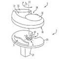
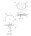
- FIG. 1is an exploded perspective view illustrating the knee prosthesis according to the present invention.
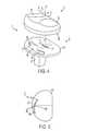
- FIGS. 2 and 3are side views showing the knee prosthesis before the plastic tibia plate is fitted on the metal base.
- FIGS. 4 and 5are views depicting a first alternative form of the knee prosthesis according to the invention.
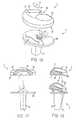
- FIGS. 6 , 7 and 8are views showing a second alternative form of the knee prosthesis in which the metal base has, on its axis of rotation, a peg for retaining the plastic tibia plate.
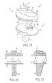
- FIGS. 9 , 10 and 11are views showing a third alternative form of the knee prosthesis in which the metal base has, on its axis of rotation, an additional peg for centering the plastic tibia plate.
- FIGS. 12 , 13 and 14are views depicting a fourth alternative form of the knee prosthesis which has a cutout through which the posterior cruciate ligament can pass.
- FIGS. 15 to 21are views illustrating alternative forms of the knee prosthesis in which the metal base has two opposed guide upstands but one of which is borne by the center of rotation of the second.
- FIGS. 22 to 24are views depicting other alternative forms of the knee prosthesis according to the present invention.
- FIGS. 25 and 26are views illustrating a guide mechanism set out at the periphery of the metal base and of the tibia plate of the knee prosthesis.
- FIGS. 27 to 29are views showing a guide mechanism utilizing at least two vertical pegs integral with the metal base and which engage with a housing formed in the tibia plate.
- FIGS. 1 to 3show a knee prosthesis 1 comprising a metal base 2 and a tibia plate 3 , whereas the femoral element is not depicted.
- the metal base 2consists of a horizontal disk 20 secured on one of its faces to an anchoring rod 21 allowing the base 2 to be fixed into the tibia of a patient.
- the horizontal disk 20comprises, on the opposite side to the rod 21 , a guide mechanism which utilizes an upstand 22 with an exterior profile in the shape of an arc of a circle.
- the center of rotation C of the upstand 22is borne by the tibia bone vertical axis YY′.
- the upstand 22 extending vertically above the horizontal disk 20has a central part 23 integral on each side with two vertical edges 24 and 25 which are not as tall as the central part 23 .
- the upstand 22is positioned on the horizontal disk 20 of the metal base 2 a certain distance away from the center of rotation C.
- the tibia plate 3which is made of plastic, has a flat lower face 30 arranged in a horizontal plane parallel to the plane containing the disk 20 of the metal base 2 .
- the tibia plate 3On the opposite side to the face 30 the tibia plate 3 has an upper face 31 with two tracks 32 and 33 of concave profile which are intended to receive the condyles of the femoral element, not depicted.
- the lower face 30is pierced with a housing 34 with the same radius of curvature as the upstand 22 secured to the metal plate 2 .
- the housing 34has cutaways 35 and 36 of a larger size which are intended to receive respectively the central part 23 and the lateral edges 24 and 25 of the upstand 22 .
- the tibia plate 3and more particularly its lower face 30 , is resting on the horizontal disk 20 of the metal base 2 , that the upstand 22 enters the housing 34 .
- the latterhas dimensions that exceed those of the upstand 22 so that the tibia plate 3 can slide freely in rotation about the center of rotation C of the upstand 22 in the direction of the arrow F illustrated in FIG. 1 .
- the upstand 22which is in the shape of an arc of a circle or curved, is positioned in the anterior part of the metal base 2 and oriented in a substantially medio-lateral direction.
- FIGS. 4 and 5show a first alternative form of the knee prosthesis 1 according to the present invention.
- the knee prosthesis 1is identical to the one described earlier, that is to say that it comprises a metal base 2 and a plastic tibia plate 3 .
- the metal base 2has, and this is what differentiates it from the one described above, the position of the guide mechanism on the horizontal disk 20 .
- the guide mechanismutilizes an upstand 22 in the shape of an arc of a circle and the profile of which is similar to the one described earlier, but the center of rotation C′ of which is offset from that C borne by the tibia bone vertical axis YY′.
- center of rotation C′can be positioned anywhere, either on the horizontal disk 20 or off it, while at the same time keeping the guide mechanism on the horizontal disk 20 and more specifically at a particular point.
- the upstand 22provided with its central part 23 and its lateral edges 24 and 25 enters the housing 34 formed in the lower face 30 of the plastic tibia plate 3 to allow the latter to slide in rotation over the metal base 2 and about the center of rotation C′ in the direction of the arrow F 1 in FIG. 4 .
- the upstand 22which is in the shape of an arc of a circle or curved, is positioned in the anterior part of the metal base 2 and oriented in a substantially medio-lateral direction.
- FIGS. 6-8illustrate a second alternative form of the knee prosthesis 1 according to the present invention.
- the knee prosthesis 1is identical to the one described in FIGS. 1 to 3 , namely it comprises a metal base 2 and a plastic tibia plate 3 .
- the metal base 2comprises, on its horizontal disk 20 , and on the opposite side to its anchoring rod 21 , guide mechanism which utilizes the upstand 22 formed from a central part 23 and of two lateral edges 24 and 25 .
- the horizontal disk 20comprises, at the center of rotation C of the upstand 22 which is borne by the tibia bone vertical axis YY′, a retaining peg 26 extending vertically above the said disk 20 .
- the retaining peg 26constitutes a guide means that is in addition to the guide means formed by the upstand 22 .
- the peg 26is positioned on the center of rotation C of the tibia plate 3 on the metal base 2 .
- the retaining peg 26consists of a cylindrical pin 27 integral with a head 28 whose outside diameter exceeds that of the pin.
- the additional guide mechanism or peg 26is an integral part of the pin 27 , 28 to prevent the tibia plate 3 from lifting off the metal base 2 when the prosthesis is in motion.
- the tibia plate 3has, on its lower face 30 , the housing 34 that receives the upstand 22 and a cutout 35 with inclined faces 36 .
- this cutoutengages with the retaining peg 26 so that the head 28 lies above the inclined faces 36 .
- the retaining peg 26when it engages with the cutout 35 , allows the tibia plate 3 to be prevented from lifting under a tensile force when the plate is sliding in rotation F 4 on the metal base 2 .
- FIGS. 9 to 11show a third alternative form of the knee prosthesis 1 according to the invention.
- the metal base 2comprises, opposite the upstand 22 , and in the region of the center of rotation C which is borne by the tibia bone vertical axis YY′, a centering peg 29 extending vertically above the horizontal disk 20 .
- the centering peg 29extends vertically above the horizontal disk 20 by a short height, constituting a guide mechanism that is in addition to the guide mechanism formed by the upstand 22 .
- the centering peg 29consists of a short cylindrical pin.
- the plastic tibia plate 3comprises, on its lower face 30 and opposite the housing 34 , a blind hole 37 intended to receive the centering peg 29 when the plate is fitted onto the metal base 2 .
- the centering peg 29provides a physical embodiment of the center of rotation C of the upstand 22 as the tibia plate 3 slides in rotation over the metal base 2 .
- the knee prosthesis 1 illustrated in FIGS. 12 to 14differs from the one shown in FIGS. 1 to 3 only in the fact that the metal base 2 and the plastic tibia plate 3 respectively comprise a cutout 4 and 38 for the passage of the posterior cruciate ligament.
- FIGS. 12 to 14works in the same way as the one described in FIGS. 1 to 3 .
- FIG. 15shows the knee prosthesis 1 equipped with its metal base 2 and with its tibia plate 3 .
- the metal base 2comprises, on its horizontal disk 20 , and more specifically on the opposite side to the anchoring rod 21 , an upstand 5 in the shape of an arc of a circle and of variable height.
- This upstandhas a profile which differs from those that make up the upstands described earlier.
- the upstands 5 and 6engage in housings, not depicted, but formed on the face 30 of the tibia plate 3 to allow the plate to be guided as it slides in rotation about the center of rotation C, as depicted by the arrow F 5 .
- the upstand 5in the shape of an arc of a circle or curved, is positioned in the anterior part of the metal base 2 and oriented in a substantially medio-lateral direction.
- the upstand 6constitutes a guide mechanism that is in addition to the guide mechanism formed by the upstand 5 .
- the upstand 6is positioned on the center of rotation C of the tibia plate 3 on the metal base 2 .
- FIGS. 16 to 18depict an alternative form of the knee prosthesis 1 shown in FIG. 15 , namely wherein the upstand 6 is integral with a flange 60 forming a kind of small plate set out in a horizontal plane parallel to the plane containing the disk 20 of the metal base 2 .
- the tibia plate 3has, on its face 30 , housings 7 and 8 intended to receive respectively the upstands 5 and 6 to allow the tibia plate 3 to slide in rotation over the metal base 2 above the center of rotation C and in the direction of the arrow F 5 .
- the housing 7has a profile essentially identical to that of the upstand 5 , and at the very least, in the shape of an arc of a circle for guiding the tibia plate 3 in its travel.
- the housing 8has a profile essentially identical to the flange 60 of the additional guide mechanism or upstand 6 for guiding the tibia plate 3 in its travel.
- the housing 8is pierced with an internal slot 80 intended to receive the flange 60 of the upstand 6 to achieve a kind of snap-fastening of the tibia plate 3 to the base 2 , so that the plate cannot lift under a tensile force.
- upstands 5 and 6 in the shape of an arc of a circleare curved in the same direction and about the same center of rotation C or C′ when the latter is offset from the tibia bone vertical axis YY′.
- the metal base 2 and the tibia plate 3may respectively comprise cutouts 4 and 38 for the passage of the posterior cruciate ligament.
- the knee prosthesis 1comprises, on its metal base 2 , a first upstand 5 ′ set out at the external periphery of the horizontal disk 20 .
- the horizontal disk 20is secured to another upstand 9 in the shape of an arc of a circle, but the radius of curvature of which is inverted compared with that of the upstand 5 ′.
- the upstand 5which is in the shape of an arc of a circle or curved, is positioned in the anterior part of the metal base 2 and oriented in a substantially medio-lateral direction.
- the upstand 9constitutes a guide mechanism that is in addition to the guide mechanism formed by the upstand 5 ′.
- the upstand 9is positioned on the center of rotation C of the tibia plate 3 on the metal base 2 .
- the upstand 9has the same center of rotation C as the upstand 5 ′, but the center may be offset, depending on the configuration of the knee prosthesis, from the tibia bone vertical axis YY′.
- the upstand 9is integral with a flange 90 , the function of which will be seen more clearly later.
- the tibia plate 3has, on its lower periphery, that is to say the one that lies between the faces 30 and 31 , a recess 10 receiving the upstand 5 ′ when the tibia plate 3 is fitted onto the metal base 2 .
- the lower face 30is pierced with a housing 12 into which the upstand 9 can be snap-fastened to, on the one hand, guide the plate 3 as it slides in rotation about its center C, and, on the other hand, retain the plate to prevent it from lifting off the metal base 2 .
- the knee prosthesis 1comprises the metal base 2 , the horizontal disk 20 of which has, on its external periphery, an upstand 13 in the shape of an arc of a circle integral with a flange 14 directed toward the tibia bone vertical axis YY′.
- the horizontal disk 20is pierced at the center of rotation C of the upstand 13 with a dish-shaped housing 15 which constitutes a guide mechanism that is in addition to the guide mechanism formed by the upstand 13 .
- This upstandwhich is in the shape of an arc of a circle or curved, is positioned in the anterior part of the metal base 2 and oriented in a substantially medio-lateral direction.
- the upstand 13 and the housing 15may comprise a center of rotation C which is offset from the tibia bone vertical axis YY′.
- the tibia plate 3On its external periphery and between the faces 30 and 31 , the tibia plate 3 has a recess 10 ′ in which there is formed a horizontal slot 16 intended to receive the flange 14 of the upstand 13 as the plate 3 slides in rotation over the metal base 2 .
- the lower face 30is integral with as stub 17 with a conical tapering profile capable of engaging with the housing 15 formed in the horizontal disk 20 of the metal base 2 .
- the upstand 13 equipped with its flange 14 , the housing 15 , the recess 10 ′ and its slot 16 , and the stub 17constitutes the mechanism of guiding the tibia plate 3 over the metal base 2 as the plate slides in rotation in the direction of the arrow F 5 .
- the metal base 2 of the knee prosthesis 1comprises, on its horizontal disk 20 , three peripheral upstands 50 , 51 and 52 extending vertically above the horizontal disk 20 .
- the tibia plate 3comprises, on its external periphery, three peripheral recesses 53 , 54 and 55 which are intended to receive the upstands 50 , 51 and 52 respectively to allow the plate to be guided as it slides in rotation about the center of rotation of the upstands, which is identical for all three.
- the upstand 51which is the shape of an arc of a circle or curved, is positioned in the anterior part of the metal base 2 and oriented in a substantially medio-lateral direction.
- the upstands 50 , 52 in the shape of an arc of a circleconstitute guide mechanism which are in addition to the guide mechanism formed by the upstand 51 .
- the upstands 50 , 52are positioned near the center of rotation C of the tibia plate 3 on the metal base 2 .
- the metal base 2 of the knee prosthesis 1comprises, on its horizontal disk 20 , vertical page 18 set out in an arc of a circle about a center of rotation C which may be either borne by or offset from the tibia bone vertical axis YY′.
- the pegs 18 set out in an arc of a circleare positioned in the anterior part of the metal base 2 and oriented in a substantially medio-lateral direction.
- the tibia plate 3is identical to the one described in FIGS. 1 to 3 , that is to say that its lower face 30 has a housing 34 intended to receive the pegs 18 for guiding the plate as it slides in rotation with respect to the metal base 2 .
- cutouts 4 and 38may or may not be provided for the passage of the posterior cruciate ligament.
- the short height of the upstand or of the pegs, and its anterior position on the metal base 2allows the plastic plate 3 to be fitted onto the base easily using a strictly anterior approach, the plate requiring upward clearance only by the height of the upstand or of the pegs as shown in FIG. 21 .
- plastic plate 3cannot slide in rotation over the metal base 2 except within the limits set by the difference in dimensions between the housing and the corresponding upstand or pegs, and this prevents any undesired excess movement.
- a plastic plate 3can be obtained in which the dimensions of the housing are identical to those of the upstand or of the corresponding pegs, so as to prevent any travel of the plate over the metal 2 . This allows the surgeon, according to the particular surgical case, to return to a knee prosthesis system with plastic plate which is fixed to the metal base 2 , without having to change the latter.
Landscapes
- Health & Medical Sciences (AREA)
- Orthopedic Medicine & Surgery (AREA)
- Physical Education & Sports Medicine (AREA)
- Cardiology (AREA)
- Oral & Maxillofacial Surgery (AREA)
- Transplantation (AREA)
- Engineering & Computer Science (AREA)
- Biomedical Technology (AREA)
- Heart & Thoracic Surgery (AREA)
- Vascular Medicine (AREA)
- Life Sciences & Earth Sciences (AREA)
- Animal Behavior & Ethology (AREA)
- General Health & Medical Sciences (AREA)
- Public Health (AREA)
- Veterinary Medicine (AREA)
- Prostheses (AREA)
Abstract
Description
Claims (17)
Priority Applications (1)
| Application Number | Priority Date | Filing Date | Title |
|---|---|---|---|
| US11/143,742US7951204B2 (en) | 1997-09-23 | 2005-06-03 | Knee prosthesis with a rotational plate |
Applications Claiming Priority (6)
| Application Number | Priority Date | Filing Date | Title |
|---|---|---|---|
| FR9712042 | 1997-09-23 | ||
| FRFR9712042 | 1997-09-23 | ||
| FR9712042AFR2768613B1 (en) | 1997-09-23 | 1997-09-23 | KNEE PROSTHESIS WITH ROTATABLE PLATFORM |
| US09/158,791US6299646B1 (en) | 1997-09-23 | 1998-09-23 | Knee prosthesis with a rotational plate |
| US09/832,874US20010014827A1 (en) | 1997-09-23 | 2001-04-12 | Knee prosthesis with a rotational plate |
| US11/143,742US7951204B2 (en) | 1997-09-23 | 2005-06-03 | Knee prosthesis with a rotational plate |
Related Parent Applications (1)
| Application Number | Title | Priority Date | Filing Date |
|---|---|---|---|
| US09/832,874ContinuationUS20010014827A1 (en) | 1997-09-23 | 2001-04-12 | Knee prosthesis with a rotational plate |
Publications (2)
| Publication Number | Publication Date |
|---|---|
| US20060015185A1 US20060015185A1 (en) | 2006-01-19 |
| US7951204B2true US7951204B2 (en) | 2011-05-31 |
Family
ID=9511543
Family Applications (3)
| Application Number | Title | Priority Date | Filing Date |
|---|---|---|---|
| US09/158,791Expired - LifetimeUS6299646B1 (en) | 1997-09-23 | 1998-09-23 | Knee prosthesis with a rotational plate |
| US09/832,874AbandonedUS20010014827A1 (en) | 1997-09-23 | 2001-04-12 | Knee prosthesis with a rotational plate |
| US11/143,742Expired - Fee RelatedUS7951204B2 (en) | 1997-09-23 | 2005-06-03 | Knee prosthesis with a rotational plate |
Family Applications Before (2)
| Application Number | Title | Priority Date | Filing Date |
|---|---|---|---|
| US09/158,791Expired - LifetimeUS6299646B1 (en) | 1997-09-23 | 1998-09-23 | Knee prosthesis with a rotational plate |
| US09/832,874AbandonedUS20010014827A1 (en) | 1997-09-23 | 2001-04-12 | Knee prosthesis with a rotational plate |
Country Status (5)
| Country | Link |
|---|---|
| US (3) | US6299646B1 (en) |
| EP (2) | EP1350487A1 (en) |
| DE (1) | DE69831116T2 (en) |
| ES (1) | ES2247669T3 (en) |
| FR (1) | FR2768613B1 (en) |
Cited By (23)
| Publication number | Priority date | Publication date | Assignee | Title |
|---|---|---|---|---|
| US20130184829A1 (en)* | 2007-09-28 | 2013-07-18 | Joseph G. Wyss | Fixed-bearing knee prosthesis having interchangeable components |
| US20130184830A1 (en)* | 2007-09-25 | 2013-07-18 | Stephen A. Hazebrouck | Fixed-bearing knee prosthesis having interchangeable components |
| US20130325130A1 (en)* | 2012-05-31 | 2013-12-05 | Howmedica Osteonics Corp. | Lateral entry insert for cup trial |
| US8906102B2 (en) | 2012-05-31 | 2014-12-09 | Howmedica Osteonics Corp. | Lateral entry insert for cup trial |
| US9011547B2 (en) | 2010-01-21 | 2015-04-21 | Depuy (Ireland) | Knee prosthesis system |
| US20150250472A1 (en)* | 2014-03-07 | 2015-09-10 | Arthrosurface Incorporated | Delivery System for Articular Surface Implant |
| US9421106B2 (en) | 2011-12-07 | 2016-08-23 | Howmedica Osteonics Corp. | Reverse shoulder baseplate with alignment guide for glenosphere |
| US9610168B2 (en) | 2014-05-12 | 2017-04-04 | Integra Lifesciences Corporation | Total ankle replacement prosthesis |
| US9681960B2 (en) | 2014-05-16 | 2017-06-20 | Howmedica Osteonics Corp. | Guides for fracture system |
| WO2019028344A1 (en)* | 2017-08-04 | 2019-02-07 | Arthrosurface Incorporated | Multicomponent articular surface implant |
| US10307172B2 (en) | 2012-07-03 | 2019-06-04 | Arthrosurface Incorporated | System and method for joint resurfacing and repair |
| US10390972B2 (en) | 2016-01-15 | 2019-08-27 | Howmedica Osteonics Corp. | Humeral trial adaptor |
| US10478200B2 (en) | 2009-04-17 | 2019-11-19 | Arthrosurface Incorporated | Glenoid resurfacing system and method |
| US10575968B2 (en) | 2014-05-16 | 2020-03-03 | Howmedica Osteonics Corp. | Guides for fracture system |
| US10624749B2 (en) | 2003-02-24 | 2020-04-21 | Arthrosurface Incorporated | Trochlear resurfacing system and method |
| US10624748B2 (en) | 2014-03-07 | 2020-04-21 | Arthrosurface Incorporated | System and method for repairing articular surfaces |
| US10624752B2 (en) | 2006-07-17 | 2020-04-21 | Arthrosurface Incorporated | Tibial resurfacing system and method |
| US10695096B2 (en) | 2013-04-16 | 2020-06-30 | Arthrosurface Incorporated | Suture system and method |
| US10945743B2 (en) | 2009-04-17 | 2021-03-16 | Arthrosurface Incorporated | Glenoid repair system and methods of use thereof |
| US10959740B2 (en) | 2006-12-11 | 2021-03-30 | Arthrosurface Incorporated | Retrograde resection apparatus and method |
| US11478358B2 (en) | 2019-03-12 | 2022-10-25 | Arthrosurface Incorporated | Humeral and glenoid articular surface implant systems and methods |
| US11607319B2 (en) | 2014-03-07 | 2023-03-21 | Arthrosurface Incorporated | System and method for repairing articular surfaces |
| US11712276B2 (en) | 2011-12-22 | 2023-08-01 | Arthrosurface Incorporated | System and method for bone fixation |
Families Citing this family (110)
| Publication number | Priority date | Publication date | Assignee | Title |
|---|---|---|---|---|
| FR2768613B1 (en)* | 1997-09-23 | 1999-12-17 | Tornier Sa | KNEE PROSTHESIS WITH ROTATABLE PLATFORM |
| CA2279660C (en)* | 1998-08-05 | 2004-02-24 | Biomedical Engineering Trust I | Knee joint prosthesis with spinout prevention |
| US6319283B1 (en)* | 1999-07-02 | 2001-11-20 | Bristol-Myers Squibb Company | Tibial knee component with a mobile bearing |
| FR2797178B1 (en)* | 1999-08-05 | 2002-02-22 | Tornier Sa | MALLEOLAR IMPLANT FOR PARTIAL OR TOTAL ANKLE PROSTHESIS AND ANCILLARY MATERIAL FOR PLACING SUCH AN IMPLANT |
| US6558426B1 (en) | 2000-11-28 | 2003-05-06 | Medidea, Llc | Multiple-cam, posterior-stabilized knee prosthesis |
| US6719800B2 (en) | 2001-01-29 | 2004-04-13 | Zimmer Technology, Inc. | Constrained prosthetic knee with rotating bearing |
| FR2824261B1 (en) | 2001-05-04 | 2004-05-28 | Ldr Medical | INTERVERTEBRAL DISC PROSTHESIS AND IMPLEMENTATION METHOD AND TOOLS |
| FR2826859B1 (en)* | 2001-07-09 | 2003-09-19 | Tornier Sa | ANCILLARY OF LAYING OF A HUMERAL COMPONENT OF ELBOW PROSTHESIS |
| FR2826860B1 (en)* | 2001-07-09 | 2004-03-05 | Tornier Sa | ANCILLARY OF POSITION OF A CUBITAL COMPONENT AND / OR A RADIAL COMPONENT OF ELBOW PROSTHESIS |
| FR2827500B1 (en)* | 2001-07-17 | 2004-04-02 | Tornier Sa | PLATE OF OSTEOSYNTHESIS OF THE UPPER END OF THE HUMERUS |
| FR2830435B1 (en) | 2001-10-10 | 2004-07-16 | Pierre Brugere | TIBIAL IMPLANT WITH MOBILE PLATE FOR KNEE PROSTHESIS |
| US6946001B2 (en)* | 2003-02-03 | 2005-09-20 | Zimmer Technology, Inc. | Mobile bearing unicompartmental knee |
| FR2846550B1 (en) | 2002-11-05 | 2006-01-13 | Ldr Medical | INTERVERTEBRAL DISC PROSTHESIS |
| FR2848183B1 (en)* | 2002-12-10 | 2006-01-27 | Tornier Sa | STERILE CONDITIONING METHOD OF A POLYETHYLENE PROTHETIC IMPLANT |
| FR2850010B1 (en)* | 2003-01-17 | 2005-12-02 | Tornier Sa | ANCILLARY FOR THE INSTALLATION OF A PROTHETIC COTYL FOR A HIP PROSTHESIS |
| US7033397B2 (en)* | 2003-02-03 | 2006-04-25 | Zimmer Technology, Inc. | Mobile bearing unicondylar tibial knee prosthesis |
| US8105386B2 (en)* | 2003-02-04 | 2012-01-31 | Zimmer, Inc. | Rotating/non-rotating tibia base plate/insert system |
| US7887544B2 (en) | 2003-03-10 | 2011-02-15 | Tornier Sas | Ancillary tool for positioning a glenoid implant |
| FR2854792B1 (en)* | 2003-05-12 | 2005-09-09 | Tornier Sa | GAME OF PROTHETIC ELEMENTS FOR A TIBIAL PROTHETIC SET |
| FR2855397B1 (en) | 2003-05-28 | 2005-07-15 | Tornier Sa | ELBOW PROSTHESIS |
| US7559931B2 (en) | 2003-06-09 | 2009-07-14 | OrthAlign, Inc. | Surgical orientation system and method |
| US7422605B2 (en)* | 2003-07-17 | 2008-09-09 | Exactech, Inc. | Mobile bearing knee prosthesis |
| US7708782B2 (en)* | 2003-07-17 | 2010-05-04 | Exactech, Inc. | Mobile bearing knee prosthesis |
| US7534270B2 (en)* | 2003-09-03 | 2009-05-19 | Integra Lifesciences Corporation | Modular total ankle prosthesis apparatuses and methods |
| US20050055100A1 (en)* | 2003-09-08 | 2005-03-10 | Lewis Ralph Harrison | Total knee replacement for dogs |
| WO2005055871A2 (en)* | 2003-12-03 | 2005-06-23 | Nebojsa Kovacevic | Prosthetic shock absorber |
| FR2863865B1 (en) | 2003-12-19 | 2006-10-06 | Tornier Sa | SHOULDER OR HIP PROSTHESIS AND METHOD OF MOUNTING |
| FR2865629B1 (en) | 2004-02-04 | 2007-01-26 | Ldr Medical | INTERVERTEBRAL DISC PROSTHESIS |
| EP2113227B1 (en) | 2004-02-04 | 2015-07-29 | LDR Medical | Intervertebral disc prosthesis |
| FR2865928B1 (en) | 2004-02-10 | 2006-03-17 | Tornier Sa | SURGICAL DEVICE FOR IMPLANTATION OF A TOTAL HIP PROSTHESIS |
| EP1574185B1 (en)* | 2004-03-09 | 2012-05-23 | Zimmer Technology, Inc. | Tibial knee component with a mobile bearing |
| FR2869528B1 (en) | 2004-04-28 | 2007-02-02 | Ldr Medical | INTERVERTEBRAL DISC PROSTHESIS |
| US8303665B2 (en) | 2004-06-15 | 2012-11-06 | Tornier Sas | Glenoidal component, set of such components and shoulder prosthesis incorporating such a glenoidal component |
| FR2871368B1 (en) | 2004-06-15 | 2006-08-25 | Tornier Sas | SET OF HUMERAL COMPONENTS FOR TOTAL SHOULDER PROSTHESIS |
| US7678150B2 (en) | 2004-06-15 | 2010-03-16 | Tornier Sas | Total shoulder prosthesis of an inverted type |
| FR2871371B1 (en) | 2004-06-15 | 2007-04-06 | Tornier Sas | GLENOIDAL COMPONENT OF SHOULDER PROSTHESIS, SET OF COMPONENT ELEMENTS OF SUCH COMPONENT AND TOTAL SHOULDER PROSTHESIS INCORPORATING SUCH COMPONENT |
| FR2872025B1 (en)* | 2004-06-28 | 2006-08-25 | Tornier Sas | PROSTHESIS OF SHOULDER OR HIP |
| EP1809209A2 (en)* | 2004-08-19 | 2007-07-25 | Kinetikos Medical Incorporated | Modular total ankle prosthesis apparatuses, systems and methods, and systems and methods for bone resection and prosthetic implantation |
| FR2879436B1 (en) | 2004-12-22 | 2007-03-09 | Ldr Medical | INTERVERTEBRAL DISC PROSTHESIS |
| FR2881340B1 (en)* | 2005-02-01 | 2008-01-11 | Tornier Sas | HUMERAL NUTS |
| FR2884408B1 (en)* | 2005-04-13 | 2007-05-25 | Tornier Sas | SURGICAL DEVICE FOR IMPLANTATION OF A PARTIAL OR TOTAL KNEE PROSTHESIS |
| FR2884407B1 (en)* | 2005-04-13 | 2007-05-25 | Tornier Sas | SURGICAL DEVICE FOR IMPLANTATION OF A PARTIAL OR TOTAL KNEE PROSTHESIS |
| FR2887435B1 (en)* | 2005-06-24 | 2007-10-05 | Abbott Spine Sa | INTERVERTEBRAL DISC PROSTHESIS |
| FR2887762B1 (en) | 2005-06-29 | 2007-10-12 | Ldr Medical Soc Par Actions Si | INTERVERTEBRAL DISC PROSTHESIS INSERTION INSTRUMENTATION BETWEEN VERTEBRATES |
| US7468077B2 (en)* | 2005-08-02 | 2008-12-23 | Tornier Sas | Patellar retractor and method of surgical procedure on knee |
| FR2891135B1 (en) | 2005-09-23 | 2008-09-12 | Ldr Medical Sarl | INTERVERTEBRAL DISC PROSTHESIS |
| EP1945151A4 (en)* | 2005-10-31 | 2009-09-09 | Depuy Products Inc | Modular fixed and mobile bearing prosthesis system |
| FR2893838B1 (en) | 2005-11-30 | 2008-08-08 | Ldr Medical Soc Par Actions Si | PROSTHESIS OF INTERVERTEBRAL DISC AND INSTRUMENTATION OF INSERTION OF THE PROSTHESIS BETWEEN VERTEBRATES |
| US8002841B2 (en)* | 2006-01-20 | 2011-08-23 | Synthes Usa, Llc | Method of preparing an ankle joint for replacement, joint prosthesis, and cutting alignment apparatus for use in performing an arthroplasty procedure |
| FR2896404B1 (en) | 2006-01-24 | 2008-02-29 | Tornier Sas | SURGICAL INSTRUMENTATION ASSEMBLY FOR POSTING AN ANKLE PROSTHESIS |
| FR2896684B1 (en)* | 2006-02-01 | 2008-09-26 | Tornier Soc Par Actions Simplifiee | TIBIAL IMPLANT WITH OFFSET SHAFT |
| EP1996122B1 (en)* | 2006-03-21 | 2012-11-21 | DePuy (Ireland) | Moment induced total arthroplasty prosthetic |
| CN104207863B (en)* | 2006-03-21 | 2018-09-07 | 德普伊爱尔兰无限公司 | Introduce the total joint replacement prosthese of torque |
| FR2899790B1 (en) | 2006-04-13 | 2008-06-13 | Tornier Sas | GLENOIDAL COMPONENT FOR TOTAL SHOULDER PROSTHESIS, SET OF SUCH COMPONENTS, AND TOTAL SHOULDER PROSTHESIS COMPRISING SUCH A COMPONENT |
| FR2900045B1 (en) | 2006-04-21 | 2009-01-16 | Tornier Sas | PROSTHESIS OF SHOULDER OR HIP |
| FR2901690B1 (en)* | 2006-06-01 | 2008-12-26 | Evolutis Sa | TOTAL SLIDING KNEE PROSTHESIS |
| US20080114463A1 (en)* | 2006-10-13 | 2008-05-15 | Auger Daniel D | Mobile/fixed prosthetic knee systems |
| FR2906999B1 (en) | 2006-10-13 | 2009-06-05 | Tornier Sas | PROTHETIC SET OF ANKLE |
| US7740662B2 (en)* | 2006-10-13 | 2010-06-22 | Depuy Products, Inc. | Mobile/fixed prosthetic knee systems |
| US20080091273A1 (en)* | 2006-10-13 | 2008-04-17 | Hazebrouck Stephen A | Mobile/fixed prosthetic knee systems |
| US20080091272A1 (en)* | 2006-10-13 | 2008-04-17 | Aram Luke J | Mobile/fixed prosthetic knee systems |
| WO2008058205A1 (en) | 2006-11-07 | 2008-05-15 | Biomedflex, Llc | Medical implants |
| US8512413B2 (en) | 2006-11-07 | 2013-08-20 | Biomedflex, Llc | Prosthetic knee joint |
| US8029574B2 (en)* | 2006-11-07 | 2011-10-04 | Biomedflex Llc | Prosthetic knee joint |
| US8070823B2 (en)* | 2006-11-07 | 2011-12-06 | Biomedflex Llc | Prosthetic ball-and-socket joint |
| US20110166671A1 (en) | 2006-11-07 | 2011-07-07 | Kellar Franz W | Prosthetic joint |
| US8308812B2 (en) | 2006-11-07 | 2012-11-13 | Biomedflex, Llc | Prosthetic joint assembly and joint member therefor |
| US9005307B2 (en) | 2006-11-07 | 2015-04-14 | Biomedflex, Llc | Prosthetic ball-and-socket joint |
| US8465546B2 (en) | 2007-02-16 | 2013-06-18 | Ldr Medical | Intervertebral disc prosthesis insertion assemblies |
| FR2916956B1 (en) | 2007-06-08 | 2012-12-14 | Ldr Medical | INTERSOMATIC CAGE, INTERVERTEBRAL PROSTHESIS, ANCHORING DEVICE AND IMPLANTATION INSTRUMENTATION |
| US8470047B2 (en)* | 2007-09-25 | 2013-06-25 | Depuy (Ireland) | Fixed-bearing knee prosthesis |
| US7628818B2 (en)* | 2007-09-28 | 2009-12-08 | Depuy Products, Inc. | Fixed-bearing knee prosthesis having interchangeable components |
| US20110035017A1 (en)* | 2007-09-25 | 2011-02-10 | Depuy Products, Inc. | Prosthesis with cut-off pegs and surgical method |
| US8715359B2 (en) | 2009-10-30 | 2014-05-06 | Depuy (Ireland) | Prosthesis for cemented fixation and method for making the prosthesis |
| US8128703B2 (en)* | 2007-09-28 | 2012-03-06 | Depuy Products, Inc. | Fixed-bearing knee prosthesis having interchangeable components |
| US20090088861A1 (en)* | 2007-09-27 | 2009-04-02 | Finsbury (Development) Limited | Prosthesis |
| ES2422584T3 (en)* | 2007-11-02 | 2013-09-12 | Biomet Uk Ltd | Prosthesis to stimulate natural kinematics |
| US9119723B2 (en) | 2008-06-30 | 2015-09-01 | Depuy (Ireland) | Posterior stabilized orthopaedic prosthesis assembly |
| US8828086B2 (en) | 2008-06-30 | 2014-09-09 | Depuy (Ireland) | Orthopaedic femoral component having controlled condylar curvature |
| US8236061B2 (en) | 2008-06-30 | 2012-08-07 | Depuy Products, Inc. | Orthopaedic knee prosthesis having controlled condylar curvature |
| US9168145B2 (en) | 2008-06-30 | 2015-10-27 | Depuy (Ireland) | Posterior stabilized orthopaedic knee prosthesis having controlled condylar curvature |
| US8206451B2 (en) | 2008-06-30 | 2012-06-26 | Depuy Products, Inc. | Posterior stabilized orthopaedic prosthesis |
| US8192498B2 (en) | 2008-06-30 | 2012-06-05 | Depuy Products, Inc. | Posterior cructiate-retaining orthopaedic knee prosthesis having controlled condylar curvature |
| US8187335B2 (en) | 2008-06-30 | 2012-05-29 | Depuy Products, Inc. | Posterior stabilized orthopaedic knee prosthesis having controlled condylar curvature |
| US8202323B2 (en)* | 2008-07-16 | 2012-06-19 | Depuy Products, Inc. | Knee prostheses with enhanced kinematics |
| US7981159B2 (en)* | 2008-07-16 | 2011-07-19 | Depuy Products, Inc. | Antero-posterior placement of axis of rotation for a rotating platform |
| AU2009273863B2 (en) | 2008-07-24 | 2014-12-18 | OrthAlign, Inc. | Systems and methods for joint replacement |
| AU2009291743B2 (en) | 2008-09-10 | 2015-02-05 | Orthalign, Inc | Hip surgery systems and methods |
| WO2010056962A1 (en)* | 2008-11-14 | 2010-05-20 | Barker Bretell | Transiently mobile tibial engagement |
| US8915965B2 (en) | 2009-05-07 | 2014-12-23 | Depuy (Ireland) | Anterior stabilized knee implant |
| US10869771B2 (en) | 2009-07-24 | 2020-12-22 | OrthAlign, Inc. | Systems and methods for joint replacement |
| US8118815B2 (en) | 2009-07-24 | 2012-02-21 | OrthAlign, Inc. | Systems and methods for joint replacement |
| US8900316B2 (en) | 2010-01-29 | 2014-12-02 | Smith & Nephew, Inc. | Cruciate-retaining knee prosthesis |
| CA2801253C (en)* | 2010-06-01 | 2018-06-26 | Smith & Nephew, Inc. | Orthopaedic implant system and fasteners for use therein |
| FR2966343B1 (en) | 2010-10-22 | 2012-12-07 | Tornier Sa | SET OF GLENOIDIAN COMPONENTS OF SHOULDER PROSTHESIS |
| US8617250B2 (en) | 2011-06-17 | 2013-12-31 | Biomet Manufacturing, Llc | Revision knee tibial locking mechanism |
| US9814584B2 (en) | 2011-09-28 | 2017-11-14 | Depuy Ireland Unlimited Company | Fixed-bearing knee prosthesis having a locking mechanism with a concave-to-convex mating interface |
| US9549742B2 (en) | 2012-05-18 | 2017-01-24 | OrthAlign, Inc. | Devices and methods for knee arthroplasty |
| US9649160B2 (en) | 2012-08-14 | 2017-05-16 | OrthAlign, Inc. | Hip replacement navigation system and method |
| FR2994644B1 (en)* | 2012-08-24 | 2014-08-29 | Anatomic | PROTHETIC TIBIAL PLUG AND TIBIAL PROTHETIC INSERT FOR IMMOBILIZATION ON SUCH PROTHETIC TIBIAL PLUG |
| GB2512609A (en)* | 2013-04-03 | 2014-10-08 | Fitzbionics Ltd | Total knee replacement prosthesis assembly |
| US10363149B2 (en) | 2015-02-20 | 2019-07-30 | OrthAlign, Inc. | Hip replacement navigation system and method |
| US10179052B2 (en) | 2016-07-28 | 2019-01-15 | Depuy Ireland Unlimited Company | Total knee implant prosthesis assembly and method |
| CN106264801A (en)* | 2016-08-03 | 2017-01-04 | 嘉思特华剑医疗器材(天津)有限公司 | Anatomical form asymmetric Double tabletop knee-joint prosthesis |
| CA3056495A1 (en) | 2017-03-14 | 2018-09-20 | OrthAlign, Inc. | Soft tissue measurement & balancing systems and methods |
| EP3595554A4 (en) | 2017-03-14 | 2021-01-06 | OrthAlign, Inc. | Hip replacement navigation systems and methods |
| US12121450B2 (en)* | 2018-01-17 | 2024-10-22 | Knollwood Orthopedic Innovations Llc | Reverse shoulder prosthesis |
| US10898338B1 (en)* | 2018-01-17 | 2021-01-26 | Matthew Budge | Reverse shoulder prosthesis |
| CN111991125A (en)* | 2020-09-16 | 2020-11-27 | 北京爱康宜诚医疗器材有限公司 | Knee joint prosthesis |
| CN114010375B (en)* | 2022-01-06 | 2022-06-14 | 北京爱康宜诚医疗器材有限公司 | Knee joint prosthesis and processing method thereof |
Citations (76)
| Publication number | Priority date | Publication date | Assignee | Title |
|---|---|---|---|---|
| GB2061730A (en) | 1979-10-26 | 1981-05-20 | Polyzoides A J | Endoprosthetic bone joint devices |
| US4714474A (en) | 1986-05-12 | 1987-12-22 | Dow Corning Wright Corporation | Tibial knee joint prosthesis with removable articulating surface insert |
| US4728332A (en) | 1984-11-28 | 1988-03-01 | Albrektsson Bjoern | Artificial menisco-tibial joint |
| EP0346183A1 (en) | 1988-05-31 | 1989-12-13 | Societe Civile D'etude Et De Recherche De Nouvelles Protheses (Scernp) | Sliding knee prothesis |
| US4950297A (en) | 1984-12-20 | 1990-08-21 | Chas F Thackray Limited | Knee prosthesis |
| US5171289A (en) | 1990-11-19 | 1992-12-15 | Etablissements Tornier | Femoral prosthesis with cement retaining seal |
| US5282868A (en) | 1991-06-17 | 1994-02-01 | Andre Bahler | Prosthetic arrangement for a complex joint, especially knee joint |
| US5314485A (en) | 1991-09-12 | 1994-05-24 | Etablissements Tornier | Total prosthesis of the wrist |
| US5326359A (en) | 1991-11-29 | 1994-07-05 | Etablissements Tornier | Knee prosthesis with adjustable centro-medullary stem |
| US5344460A (en) | 1992-10-30 | 1994-09-06 | Encore Orthopedics, Inc. | Prosthesis system |
| US5358526A (en) | 1991-12-27 | 1994-10-25 | Etablissements Tornier | Modular shoulder prosthesis |
| EP0634156A2 (en) | 1993-07-16 | 1995-01-18 | Peter Stanley Walker | Prosthesis for knee replacement |
| FR2707871A1 (en) | 1993-07-22 | 1995-01-27 | Serf | Bicondylar knee prosthesis of the sliding type |
| US5387240A (en)* | 1990-11-14 | 1995-02-07 | Arch Development Corporation | Floating bearing prosthetic knee |
| US5405399A (en) | 1992-05-25 | 1995-04-11 | Etablissements Tornier | Total prosthesis for the metacarpo-phalangeal joint |
| US5429639A (en) | 1993-05-17 | 1995-07-04 | Tornier S.A. | Spine fixator for holding a vertebral column |
| US5458650A (en) | 1993-03-30 | 1995-10-17 | Tornier S.A. | Elastically deformable cotyloidal prosthesis |
| US5505731A (en) | 1993-09-01 | 1996-04-09 | Tornier Sa | Screw for lumbar-sacral fixator |
| FR2735017A1 (en) | 1995-06-08 | 1996-12-13 | Groupe Lepine | Movable plate for knee prosthesis |
| US5591168A (en) | 1993-10-25 | 1997-01-07 | Tornier S.A. | Device for stabilizing fractures of the upper end of the femur |
| US5658342A (en) | 1992-11-16 | 1997-08-19 | Arch Development | Stabilized prosthetic knee |
| US5662651A (en) | 1994-09-15 | 1997-09-02 | Tornier S.A. | External or internal fixator for repairing fractures or arthroplasties of the skeleton |
| US5676702A (en) | 1994-12-16 | 1997-10-14 | Tornier S.A. | Elastic disc prosthesis |
| GB2312377A (en) | 1996-04-24 | 1997-10-29 | Roozbeh Shirandami | Three part prosthetic knee joint with anterior posterior sliding action |
| US5683468A (en) | 1995-03-13 | 1997-11-04 | Pappas; Michael J. | Mobile bearing total joint replacement |
| US5702447A (en) | 1995-11-30 | 1997-12-30 | Tornier S.A. | Device for the attachment of a glenoid prosthesis of the shoulder blade |
| US5702457A (en) | 1994-11-18 | 1997-12-30 | Tornier Sa | Humeral prosthesis incorporating a sphere |
| US5702478A (en) | 1995-06-16 | 1997-12-30 | Tornier Sa | Acetabular implant intended in particular for the iliac joint socket |
| US5766256A (en) | 1996-01-23 | 1998-06-16 | Tornier Sa | Tibial prosthesis |
| US5824106A (en) | 1996-04-11 | 1998-10-20 | Tornier Sa | Ankle prosthesis |
| US5871543A (en) | 1996-02-23 | 1999-02-16 | Hofmann; Aaron A. | Tibial prosthesis with mobile bearing member |
| US5879395A (en) | 1997-01-23 | 1999-03-09 | Tornier Sa | Total elbow prosthesis |
| US5879394A (en) | 1996-05-28 | 1999-03-09 | Howmedica International Inc. | Tibial element for a replacement knee prosthesis |
| US5951603A (en)* | 1997-09-25 | 1999-09-14 | Johnson & Johnson Professional, Inc. | Rotatable joint prosthesis with axial securement |
| US6162254A (en) | 1997-10-14 | 2000-12-19 | Tornier S.A. | Knee prosthesis |
| US6165224A (en) | 1997-10-01 | 2000-12-26 | Tornier Sa | Prosthesis intended to be anchored in a long bone |
| US6168629B1 (en) | 1997-10-14 | 2001-01-02 | Tornier S.A. | Femoral component for knee prosthesis |
| US6171341B1 (en) | 1996-08-02 | 2001-01-09 | Tornier Sa | Prosthesis for the upper extremity of the humerus |
| US6183519B1 (en) | 1997-03-10 | 2001-02-06 | Tornier Sa | Ankle prosthesis |
| US6206925B1 (en) | 1997-09-12 | 2001-03-27 | Tornier Sa | Elbow prosthesis with indexed sphere |
| US6299646B1 (en) | 1997-09-23 | 2001-10-09 | Tornier Sa | Knee prosthesis with a rotational plate |
| US6328758B1 (en) | 1998-04-21 | 2001-12-11 | Tornier Sa | Suture anchor with reversible expansion |
| US6334874B1 (en) | 1999-06-09 | 2002-01-01 | Tornier Sa | Humeral prosthesis |
| US6379387B1 (en) | 1999-05-14 | 2002-04-30 | Tornier Sa | Elbow prosthesis |
| US6454809B1 (en) | 1998-03-03 | 2002-09-24 | Tornier Sa | Modular acetabular or cotyloid implant |
| US6488712B1 (en) | 1999-08-05 | 2002-12-03 | Tornier Sa | Malleolar implant for partial or total ankle prosthesis |
| US20030009170A1 (en) | 2001-07-09 | 2003-01-09 | Alain Tornier | Ancillary tool for fitting an ulnar component and/or a radial component of an elbow prosthesis |
| US20030009171A1 (en) | 2001-07-09 | 2003-01-09 | Alain Tornier | Ancillary tool for fitting a humeral component of an elbow prosthesis |
| US6540770B1 (en) | 1998-04-21 | 2003-04-01 | Tornier Sa | Reversible fixation device for securing an implant in bone |
| US6582469B1 (en) | 1997-12-12 | 2003-06-24 | Tornier S.A. | Knee prosthesis |
| US6599295B1 (en) | 1998-04-21 | 2003-07-29 | Tornier Sa | Device for setting and removing an implant such as a suture anchor |
| US6626946B1 (en) | 1996-06-25 | 2003-09-30 | Tornier Sa | Shoulder prosthesis and humeral stems for such a prosthesis |
| US6761740B2 (en) | 2002-02-15 | 2004-07-13 | Tornier | Glenoid component of a shoulder prosthesis and complete shoulder prosthesis incorporating such a component |
| US20040134821A1 (en) | 2002-12-10 | 2004-07-15 | Alain Tornier | Process for the sterile packaging of a prosthetic implant made of polyethylene |
| US6802864B2 (en) | 2001-10-30 | 2004-10-12 | Toriner Sa | Patellar implant and knee prosthesis incorporating such an implant |
| US20040210220A1 (en) | 2001-07-17 | 2004-10-21 | Alain Tornier | Osteosynthesis plate for the upper end of the arm bone |
| US20040215200A1 (en) | 2003-01-17 | 2004-10-28 | Alain Tornier | Ancillary tool and method for positioning a prosthetic acetabulum of a hip prosthesis |
| US20040230197A1 (en) | 2003-03-10 | 2004-11-18 | Alain Tornier | Ancillary tool for positioning a glenoid implant |
| US20050049709A1 (en) | 2003-08-25 | 2005-03-03 | Alain Tornier | Glenoid component of a shoulder prosthesis and complete shoulder prosthesis incorporating such a component |
| US20050055102A1 (en) | 2003-05-12 | 2005-03-10 | Alain Tornier | Set of prosthetic elements for a tibial prosthetic assembly |
| US6890357B2 (en) | 2003-05-28 | 2005-05-10 | Tornier | Elbow prosthesis |
| US20050165490A1 (en) | 2003-12-19 | 2005-07-28 | Alain Tornier | Shoulder or hip prosthesis and process for fitting same |
| US20050203536A1 (en) | 2004-02-10 | 2005-09-15 | Philippe Laffargue | Surgical device for implanting a total hip prosthesis |
| US6969406B2 (en) | 2002-02-04 | 2005-11-29 | Tornier Sa | Prosthetic element comprising two components and process for assembling such a prosthetic element |
| US20050278030A1 (en) | 2004-06-15 | 2005-12-15 | Tornier | Glenoidal component, set of such components and shoulder prosthesis incorporating such a glenoidal component |
| US20050278033A1 (en) | 2004-06-15 | 2005-12-15 | Alain Tornier | Total shoulder prosthesis or inverted type |
| US20050278031A1 (en) | 2004-06-15 | 2005-12-15 | Tomier | Set of humeral components for total shoulder prosthesis |
| US20050278032A1 (en) | 2004-06-15 | 2005-12-15 | Tornier | Glenoidal component of a shoulder prosthesis, set of elements constituting such a component and total shoulder prosthesis incorporating such a component |
| US20050288791A1 (en) | 2004-06-28 | 2005-12-29 | Tornier | Shoulder or hip prosthesis |
| US7033396B2 (en) | 2002-07-05 | 2006-04-25 | Tornier | Shoulder or hip prosthesis facilitating abduction |
| US20060173457A1 (en) | 2005-02-01 | 2006-08-03 | Tornier | Humeral nail |
| US20060235538A1 (en) | 2005-04-13 | 2006-10-19 | Tornier | Surgical apparatus for implantation of a partial of total knee prosthesis |
| US20070043265A1 (en) | 2005-08-02 | 2007-02-22 | Tornier | Patellar retractor and method of surgical procedure on knee |
| US20070173947A1 (en) | 2006-01-24 | 2007-07-26 | Tornier | surgical instrumentation kit for inserting an ankle prosthesis |
| US20070179628A1 (en) | 2006-02-01 | 2007-08-02 | Tornier | Offset stem tibial implant |
| US20070270718A1 (en) | 2005-04-13 | 2007-11-22 | Tornier | Surgical apparatus for implantation of a partial or total knee prosthesis |
Family Cites Families (1)
| Publication number | Priority date | Publication date | Assignee | Title |
|---|---|---|---|---|
| GB9823759D0 (en)* | 1998-10-31 | 1998-12-23 | Rota Limited | A safety device |
- 1997
- 1997-09-23FRFR9712042Apatent/FR2768613B1/ennot_activeExpired - Fee Related
- 1998
- 1998-09-10DEDE69831116Tpatent/DE69831116T2/ennot_activeExpired - Lifetime
- 1998-09-10ESES98420154Tpatent/ES2247669T3/ennot_activeExpired - Lifetime
- 1998-09-10EPEP03015191Apatent/EP1350487A1/ennot_activeWithdrawn
- 1998-09-10EPEP98420154Apatent/EP0903126B8/ennot_activeExpired - Lifetime
- 1998-09-23USUS09/158,791patent/US6299646B1/ennot_activeExpired - Lifetime
- 2001
- 2001-04-12USUS09/832,874patent/US20010014827A1/ennot_activeAbandoned
- 2005
- 2005-06-03USUS11/143,742patent/US7951204B2/ennot_activeExpired - Fee Related
Patent Citations (79)
| Publication number | Priority date | Publication date | Assignee | Title |
|---|---|---|---|---|
| GB2061730A (en) | 1979-10-26 | 1981-05-20 | Polyzoides A J | Endoprosthetic bone joint devices |
| US4728332A (en) | 1984-11-28 | 1988-03-01 | Albrektsson Bjoern | Artificial menisco-tibial joint |
| US4950297A (en) | 1984-12-20 | 1990-08-21 | Chas F Thackray Limited | Knee prosthesis |
| US4714474A (en) | 1986-05-12 | 1987-12-22 | Dow Corning Wright Corporation | Tibial knee joint prosthesis with removable articulating surface insert |
| EP0346183A1 (en) | 1988-05-31 | 1989-12-13 | Societe Civile D'etude Et De Recherche De Nouvelles Protheses (Scernp) | Sliding knee prothesis |
| US5387240A (en)* | 1990-11-14 | 1995-02-07 | Arch Development Corporation | Floating bearing prosthetic knee |
| US5171289A (en) | 1990-11-19 | 1992-12-15 | Etablissements Tornier | Femoral prosthesis with cement retaining seal |
| US5282868A (en) | 1991-06-17 | 1994-02-01 | Andre Bahler | Prosthetic arrangement for a complex joint, especially knee joint |
| US5314485A (en) | 1991-09-12 | 1994-05-24 | Etablissements Tornier | Total prosthesis of the wrist |
| US5326359A (en) | 1991-11-29 | 1994-07-05 | Etablissements Tornier | Knee prosthesis with adjustable centro-medullary stem |
| US5358526A (en) | 1991-12-27 | 1994-10-25 | Etablissements Tornier | Modular shoulder prosthesis |
| US5405399A (en) | 1992-05-25 | 1995-04-11 | Etablissements Tornier | Total prosthesis for the metacarpo-phalangeal joint |
| US5344460A (en) | 1992-10-30 | 1994-09-06 | Encore Orthopedics, Inc. | Prosthesis system |
| US5658342A (en) | 1992-11-16 | 1997-08-19 | Arch Development | Stabilized prosthetic knee |
| US5458650A (en) | 1993-03-30 | 1995-10-17 | Tornier S.A. | Elastically deformable cotyloidal prosthesis |
| US5429639A (en) | 1993-05-17 | 1995-07-04 | Tornier S.A. | Spine fixator for holding a vertebral column |
| EP0634156A2 (en) | 1993-07-16 | 1995-01-18 | Peter Stanley Walker | Prosthesis for knee replacement |
| FR2707871A1 (en) | 1993-07-22 | 1995-01-27 | Serf | Bicondylar knee prosthesis of the sliding type |
| US5505731A (en) | 1993-09-01 | 1996-04-09 | Tornier Sa | Screw for lumbar-sacral fixator |
| US5591168A (en) | 1993-10-25 | 1997-01-07 | Tornier S.A. | Device for stabilizing fractures of the upper end of the femur |
| US5662651A (en) | 1994-09-15 | 1997-09-02 | Tornier S.A. | External or internal fixator for repairing fractures or arthroplasties of the skeleton |
| US5702457A (en) | 1994-11-18 | 1997-12-30 | Tornier Sa | Humeral prosthesis incorporating a sphere |
| US5676702A (en) | 1994-12-16 | 1997-10-14 | Tornier S.A. | Elastic disc prosthesis |
| US5683468A (en) | 1995-03-13 | 1997-11-04 | Pappas; Michael J. | Mobile bearing total joint replacement |
| FR2735017A1 (en) | 1995-06-08 | 1996-12-13 | Groupe Lepine | Movable plate for knee prosthesis |
| US5702478A (en) | 1995-06-16 | 1997-12-30 | Tornier Sa | Acetabular implant intended in particular for the iliac joint socket |
| US5702447A (en) | 1995-11-30 | 1997-12-30 | Tornier S.A. | Device for the attachment of a glenoid prosthesis of the shoulder blade |
| US5766256A (en) | 1996-01-23 | 1998-06-16 | Tornier Sa | Tibial prosthesis |
| US5871543A (en) | 1996-02-23 | 1999-02-16 | Hofmann; Aaron A. | Tibial prosthesis with mobile bearing member |
| US5824106A (en) | 1996-04-11 | 1998-10-20 | Tornier Sa | Ankle prosthesis |
| GB2312377A (en) | 1996-04-24 | 1997-10-29 | Roozbeh Shirandami | Three part prosthetic knee joint with anterior posterior sliding action |
| US5879394A (en) | 1996-05-28 | 1999-03-09 | Howmedica International Inc. | Tibial element for a replacement knee prosthesis |
| US6626946B1 (en) | 1996-06-25 | 2003-09-30 | Tornier Sa | Shoulder prosthesis and humeral stems for such a prosthesis |
| US6171341B1 (en) | 1996-08-02 | 2001-01-09 | Tornier Sa | Prosthesis for the upper extremity of the humerus |
| US5879395A (en) | 1997-01-23 | 1999-03-09 | Tornier Sa | Total elbow prosthesis |
| US6183519B1 (en) | 1997-03-10 | 2001-02-06 | Tornier Sa | Ankle prosthesis |
| US6206925B1 (en) | 1997-09-12 | 2001-03-27 | Tornier Sa | Elbow prosthesis with indexed sphere |
| US6299646B1 (en) | 1997-09-23 | 2001-10-09 | Tornier Sa | Knee prosthesis with a rotational plate |
| US5951603A (en)* | 1997-09-25 | 1999-09-14 | Johnson & Johnson Professional, Inc. | Rotatable joint prosthesis with axial securement |
| US6165224A (en) | 1997-10-01 | 2000-12-26 | Tornier Sa | Prosthesis intended to be anchored in a long bone |
| US6162254A (en) | 1997-10-14 | 2000-12-19 | Tornier S.A. | Knee prosthesis |
| US6168629B1 (en) | 1997-10-14 | 2001-01-02 | Tornier S.A. | Femoral component for knee prosthesis |
| US6582469B1 (en) | 1997-12-12 | 2003-06-24 | Tornier S.A. | Knee prosthesis |
| US6454809B1 (en) | 1998-03-03 | 2002-09-24 | Tornier Sa | Modular acetabular or cotyloid implant |
| US6599295B1 (en) | 1998-04-21 | 2003-07-29 | Tornier Sa | Device for setting and removing an implant such as a suture anchor |
| US6540770B1 (en) | 1998-04-21 | 2003-04-01 | Tornier Sa | Reversible fixation device for securing an implant in bone |
| US6328758B1 (en) | 1998-04-21 | 2001-12-11 | Tornier Sa | Suture anchor with reversible expansion |
| US6379387B1 (en) | 1999-05-14 | 2002-04-30 | Tornier Sa | Elbow prosthesis |
| US6767368B2 (en) | 1999-05-14 | 2004-07-27 | Tornier Sa | Elbow prosthesis |
| US6334874B1 (en) | 1999-06-09 | 2002-01-01 | Tornier Sa | Humeral prosthesis |
| US6824567B2 (en) | 1999-08-03 | 2004-11-30 | Tornier | Method of positioning a malleolar implant for partial or total ankle prosthesis |
| US6488712B1 (en) | 1999-08-05 | 2002-12-03 | Tornier Sa | Malleolar implant for partial or total ankle prosthesis |
| US20030028198A1 (en) | 1999-08-05 | 2003-02-06 | Alain Tornier | Tool for placing a malleolar implant for partial or total ankle prosthesis |
| US20030009170A1 (en) | 2001-07-09 | 2003-01-09 | Alain Tornier | Ancillary tool for fitting an ulnar component and/or a radial component of an elbow prosthesis |
| US20030009171A1 (en) | 2001-07-09 | 2003-01-09 | Alain Tornier | Ancillary tool for fitting a humeral component of an elbow prosthesis |
| US20040210220A1 (en) | 2001-07-17 | 2004-10-21 | Alain Tornier | Osteosynthesis plate for the upper end of the arm bone |
| US6802864B2 (en) | 2001-10-30 | 2004-10-12 | Toriner Sa | Patellar implant and knee prosthesis incorporating such an implant |
| US6969406B2 (en) | 2002-02-04 | 2005-11-29 | Tornier Sa | Prosthetic element comprising two components and process for assembling such a prosthetic element |
| US6761740B2 (en) | 2002-02-15 | 2004-07-13 | Tornier | Glenoid component of a shoulder prosthesis and complete shoulder prosthesis incorporating such a component |
| US7033396B2 (en) | 2002-07-05 | 2006-04-25 | Tornier | Shoulder or hip prosthesis facilitating abduction |
| US20040134821A1 (en) | 2002-12-10 | 2004-07-15 | Alain Tornier | Process for the sterile packaging of a prosthetic implant made of polyethylene |
| US20040215200A1 (en) | 2003-01-17 | 2004-10-28 | Alain Tornier | Ancillary tool and method for positioning a prosthetic acetabulum of a hip prosthesis |
| US20040230197A1 (en) | 2003-03-10 | 2004-11-18 | Alain Tornier | Ancillary tool for positioning a glenoid implant |
| US20050055102A1 (en) | 2003-05-12 | 2005-03-10 | Alain Tornier | Set of prosthetic elements for a tibial prosthetic assembly |
| US6890357B2 (en) | 2003-05-28 | 2005-05-10 | Tornier | Elbow prosthesis |
| US20050049709A1 (en) | 2003-08-25 | 2005-03-03 | Alain Tornier | Glenoid component of a shoulder prosthesis and complete shoulder prosthesis incorporating such a component |
| US20050165490A1 (en) | 2003-12-19 | 2005-07-28 | Alain Tornier | Shoulder or hip prosthesis and process for fitting same |
| US20050203536A1 (en) | 2004-02-10 | 2005-09-15 | Philippe Laffargue | Surgical device for implanting a total hip prosthesis |
| US20050278032A1 (en) | 2004-06-15 | 2005-12-15 | Tornier | Glenoidal component of a shoulder prosthesis, set of elements constituting such a component and total shoulder prosthesis incorporating such a component |
| US20050278031A1 (en) | 2004-06-15 | 2005-12-15 | Tomier | Set of humeral components for total shoulder prosthesis |
| US20050278033A1 (en) | 2004-06-15 | 2005-12-15 | Alain Tornier | Total shoulder prosthesis or inverted type |
| US20050278030A1 (en) | 2004-06-15 | 2005-12-15 | Tornier | Glenoidal component, set of such components and shoulder prosthesis incorporating such a glenoidal component |
| US20050288791A1 (en) | 2004-06-28 | 2005-12-29 | Tornier | Shoulder or hip prosthesis |
| US20060173457A1 (en) | 2005-02-01 | 2006-08-03 | Tornier | Humeral nail |
| US20060235538A1 (en) | 2005-04-13 | 2006-10-19 | Tornier | Surgical apparatus for implantation of a partial of total knee prosthesis |
| US20070270718A1 (en) | 2005-04-13 | 2007-11-22 | Tornier | Surgical apparatus for implantation of a partial or total knee prosthesis |
| US20070043265A1 (en) | 2005-08-02 | 2007-02-22 | Tornier | Patellar retractor and method of surgical procedure on knee |
| US20070173947A1 (en) | 2006-01-24 | 2007-07-26 | Tornier | surgical instrumentation kit for inserting an ankle prosthesis |
| US20070179628A1 (en) | 2006-02-01 | 2007-08-02 | Tornier | Offset stem tibial implant |
Non-Patent Citations (10)
| Title |
|---|
| Advisory Office Action mailed Feb. 20, 2001 from USPTO for U.S. Appl. No. 09/158,791, Issued Patent No. 6,299,646. |
| Advisory Office Action mailed Jan. 9, 2001 from USPTO for U.S. Appl. No. 09/158,791, Issued Patent No. 6,299,646. |
| Final Office Action mailed Oct. 12, 2000 from USPTO for U.S. Appl. No. 09/158,791, Issued Patent No. 6,299,646. |
| Non-Final Office Action mailed Apr. 24, 2000 from USPTO for U.S. Appl. No. 09/158,791, Issued Patent No. 6,299,646. |
| Notice of Allowance mailed Apr. 18, 2001 from USPTO for U.S. Appl. No. 09/158,791, Issued Patent No. 6,299,646. |
| Ratron, et al., U.S. Appl. No. 11/626,735, filed Jan. 24, 2007, file wrapper. |
| Restriction Requirement Office Action mailed Mar. 17, 2000 from USPTO for U.S. Appl. No. 09/158,791, Issued Patent No. 6,299,646. |
| Rochetin, et al., U.S. Appl. No. 11/401,415, filed Apr. 11, 2006, file wrapper. |
| Rochetin, U.S. Appl. No. 11/194,452, filed Aug. 2, 2005, file wrapper. |
| Rochetin, U.S. Appl. No. 11/670,274, filed Feb. 1, 2007, file wrapper. |
Cited By (41)
| Publication number | Priority date | Publication date | Assignee | Title |
|---|---|---|---|---|
| US10624749B2 (en) | 2003-02-24 | 2020-04-21 | Arthrosurface Incorporated | Trochlear resurfacing system and method |
| US11337819B2 (en) | 2003-02-24 | 2022-05-24 | Arthrosurface Incorporated | Trochlear resurfacing system and method |
| US10624752B2 (en) | 2006-07-17 | 2020-04-21 | Arthrosurface Incorporated | Tibial resurfacing system and method |
| US11471289B2 (en) | 2006-07-17 | 2022-10-18 | Arthrosurface Incorporated | Tibial resurfacing system and method |
| US10959740B2 (en) | 2006-12-11 | 2021-03-30 | Arthrosurface Incorporated | Retrograde resection apparatus and method |
| US20130184830A1 (en)* | 2007-09-25 | 2013-07-18 | Stephen A. Hazebrouck | Fixed-bearing knee prosthesis having interchangeable components |
| US9398956B2 (en)* | 2007-09-25 | 2016-07-26 | Depuy (Ireland) | Fixed-bearing knee prosthesis having interchangeable components |
| US9204967B2 (en)* | 2007-09-28 | 2015-12-08 | Depuy (Ireland) | Fixed-bearing knee prosthesis having interchangeable components |
| US20130184829A1 (en)* | 2007-09-28 | 2013-07-18 | Joseph G. Wyss | Fixed-bearing knee prosthesis having interchangeable components |
| US11478259B2 (en) | 2009-04-17 | 2022-10-25 | Arthrosurface, Incorporated | Glenoid resurfacing system and method |
| US10945743B2 (en) | 2009-04-17 | 2021-03-16 | Arthrosurface Incorporated | Glenoid repair system and methods of use thereof |
| US10478200B2 (en) | 2009-04-17 | 2019-11-19 | Arthrosurface Incorporated | Glenoid resurfacing system and method |
| US9011547B2 (en) | 2010-01-21 | 2015-04-21 | Depuy (Ireland) | Knee prosthesis system |
| US9421106B2 (en) | 2011-12-07 | 2016-08-23 | Howmedica Osteonics Corp. | Reverse shoulder baseplate with alignment guide for glenosphere |
| US11712276B2 (en) | 2011-12-22 | 2023-08-01 | Arthrosurface Incorporated | System and method for bone fixation |
| US8906102B2 (en) | 2012-05-31 | 2014-12-09 | Howmedica Osteonics Corp. | Lateral entry insert for cup trial |
| US8858641B2 (en) | 2012-05-31 | 2014-10-14 | Howmedica Osteonics Corp. | Lateral entry insert for cup trial |
| US8663334B2 (en)* | 2012-05-31 | 2014-03-04 | Howmedica Osteonics Corp. | Lateral entry insert for cup trial |
| US20130325130A1 (en)* | 2012-05-31 | 2013-12-05 | Howmedica Osteonics Corp. | Lateral entry insert for cup trial |
| US11191552B2 (en) | 2012-07-03 | 2021-12-07 | Arthrosurface, Incorporated | System and method for joint resurfacing and repair |
| US10307172B2 (en) | 2012-07-03 | 2019-06-04 | Arthrosurface Incorporated | System and method for joint resurfacing and repair |
| US10695096B2 (en) | 2013-04-16 | 2020-06-30 | Arthrosurface Incorporated | Suture system and method |
| US11648036B2 (en) | 2013-04-16 | 2023-05-16 | Arthrosurface Incorporated | Suture system and method |
| US10624754B2 (en) | 2014-03-07 | 2020-04-21 | Arthrosurface Incorporated | System and method for repairing articular surfaces |
| US11766334B2 (en) | 2014-03-07 | 2023-09-26 | Arthrosurface Incorporated | System and method for repairing articular surfaces |
| US10624748B2 (en) | 2014-03-07 | 2020-04-21 | Arthrosurface Incorporated | System and method for repairing articular surfaces |
| US10575957B2 (en) | 2014-03-07 | 2020-03-03 | Arthrosurface Incoporated | Anchor for an implant assembly |
| US20150250472A1 (en)* | 2014-03-07 | 2015-09-10 | Arthrosurface Incorporated | Delivery System for Articular Surface Implant |
| US11083587B2 (en) | 2014-03-07 | 2021-08-10 | Arthrosurface Incorporated | Implant and anchor assembly |
| US11607319B2 (en) | 2014-03-07 | 2023-03-21 | Arthrosurface Incorporated | System and method for repairing articular surfaces |
| US9610168B2 (en) | 2014-05-12 | 2017-04-04 | Integra Lifesciences Corporation | Total ankle replacement prosthesis |
| US10166110B2 (en) | 2014-05-12 | 2019-01-01 | Integra Lifesciences Corporation | Total ankle replacement prosthesis |
| US11369481B2 (en) | 2014-05-12 | 2022-06-28 | Smith & Nephew, Inc. | Total ankle replacement prosthesis |
| US10653528B2 (en) | 2014-05-12 | 2020-05-19 | Integra Lifesciences Corporation | Total ankle replacement prosthesis |
| US12251315B2 (en) | 2014-05-12 | 2025-03-18 | Smith & Nephew, Inc. | Total ankle replacement prosthesis |
| US9681960B2 (en) | 2014-05-16 | 2017-06-20 | Howmedica Osteonics Corp. | Guides for fracture system |
| US10575968B2 (en) | 2014-05-16 | 2020-03-03 | Howmedica Osteonics Corp. | Guides for fracture system |
| US10390972B2 (en) | 2016-01-15 | 2019-08-27 | Howmedica Osteonics Corp. | Humeral trial adaptor |
| WO2019028344A1 (en)* | 2017-08-04 | 2019-02-07 | Arthrosurface Incorporated | Multicomponent articular surface implant |
| US11160663B2 (en) | 2017-08-04 | 2021-11-02 | Arthrosurface Incorporated | Multicomponent articular surface implant |
| US11478358B2 (en) | 2019-03-12 | 2022-10-25 | Arthrosurface Incorporated | Humeral and glenoid articular surface implant systems and methods |
Also Published As
| Publication number | Publication date |
|---|---|
| EP0903126B1 (en) | 2005-08-10 |
| US20060015185A1 (en) | 2006-01-19 |
| DE69831116T2 (en) | 2006-06-29 |
| EP1350487A1 (en) | 2003-10-08 |
| ES2247669T3 (en) | 2006-03-01 |
| US6299646B1 (en) | 2001-10-09 |
| US20010014827A1 (en) | 2001-08-16 |
| DE69831116D1 (en) | 2005-09-15 |
| EP0903126A1 (en) | 1999-03-24 |
| FR2768613B1 (en) | 1999-12-17 |
| EP0903126B8 (en) | 2005-10-12 |
| FR2768613A1 (en) | 1999-03-26 |
Similar Documents
| Publication | Publication Date | Title |
|---|---|---|
| US7951204B2 (en) | Knee prosthesis with a rotational plate | |
| US6514287B2 (en) | Modular glenoid assembly having bearing insert | |
| US5928286A (en) | Tibial element for a replacement knee prosthesis | |
| US5755801A (en) | Prostheses for knee replacement | |
| EP0809987B1 (en) | Tibial element for a replacement knee prosthesis | |
| US6068658A (en) | Prosthesis for knee replacement | |
| EP1095639B1 (en) | Tibial knee component with a mobile bearing | |
| US4959071A (en) | Partially stabilized knee prosthesis | |
| AU2002346916B2 (en) | Intravertebral prosthesis | |
| JPH11313843A (en) | Acetabular prosthesis with ring-like lock mechanism | |
| ES2368422T3 (en) | ARTICULATION OF KNEE PROTESIC. | |
| US6443991B1 (en) | Posterior stabilized mobile bearing knee | |
| EP2042131B1 (en) | Fixed-bearing knee prosthesis | |
| EP2575690B1 (en) | Semi-constrained ankle prosthesis having a rotating bearing insert | |
| US5032132A (en) | Glenoid component | |
| EP1413264A2 (en) | Tibial knee component with a mobile bearing | |
| US5782926A (en) | Wrist prosthesis | |
| KR20030094367A (en) | Knee prosthesis with rotation bearing | |
| US20050256579A1 (en) | Intervertebral prosthesis | |
| EP0728450A2 (en) | Oval patellar prosthesis having dome shaped contact surface for trochlear groove | |
| EP0634155A2 (en) | Prosthesis for knee replacement |
Legal Events
| Date | Code | Title | Description |
|---|---|---|---|
| AS | Assignment | Owner name:TORNIER SA, FRANCE Free format text:ASSIGNMENT OF ASSIGNORS INTEREST;ASSIGNORS:CHAMBAT, PIERRE;DESCHAMPS, GERARD;JUDET, THIERRY;AND OTHERS;REEL/FRAME:020484/0343 Effective date:19980910 | |
| AS | Assignment | Owner name:TORNIER SAS, FRANCE Free format text:ASSIGNMENT OF ASSIGNORS INTEREST;ASSIGNOR:TORNIER SA;REEL/FRAME:020963/0611 Effective date:20080417 | |
| STCF | Information on status: patent grant | Free format text:PATENTED CASE | |
| FPAY | Fee payment | Year of fee payment:4 | |
| AS | Assignment | Owner name:CORIN FRANCE SAS, FRANCE Free format text:ASSIGNMENT OF ASSIGNORS INTEREST;ASSIGNOR:TORNIER SAS;REEL/FRAME:041009/0288 Effective date:20161021 | |
| AS | Assignment | Owner name:CORIN LIMITED, UNITED KINGDOM Free format text:ASSIGNMENT OF ASSIGNORS INTEREST;ASSIGNOR:CORIN FRANCE SAS;REEL/FRAME:041045/0311 Effective date:20161105 | |
| MAFP | Maintenance fee payment | Free format text:PAYMENT OF MAINTENANCE FEE, 8TH YEAR, LARGE ENTITY (ORIGINAL EVENT CODE: M1552); ENTITY STATUS OF PATENT OWNER: LARGE ENTITY Year of fee payment:8 | |
| FEPP | Fee payment procedure | Free format text:MAINTENANCE FEE REMINDER MAILED (ORIGINAL EVENT CODE: REM.); ENTITY STATUS OF PATENT OWNER: LARGE ENTITY | |
| LAPS | Lapse for failure to pay maintenance fees | Free format text:PATENT EXPIRED FOR FAILURE TO PAY MAINTENANCE FEES (ORIGINAL EVENT CODE: EXP.); ENTITY STATUS OF PATENT OWNER: LARGE ENTITY | |
| STCH | Information on status: patent discontinuation | Free format text:PATENT EXPIRED DUE TO NONPAYMENT OF MAINTENANCE FEES UNDER 37 CFR 1.362 | |
| FP | Lapsed due to failure to pay maintenance fee | Effective date:20230531 |