US7950833B1 - Splay frame luminaire - Google Patents
Splay frame luminaireDownload PDFInfo
- Publication number
- US7950833B1 US7950833B1US12/140,520US14052008AUS7950833B1US 7950833 B1US7950833 B1US 7950833B1US 14052008 AUS14052008 AUS 14052008AUS 7950833 B1US7950833 B1US 7950833B1
- Authority
- US
- United States
- Prior art keywords
- luminaire
- lens
- members
- frame
- housing
- Prior art date
- Legal status (The legal status is an assumption and is not a legal conclusion. Google has not performed a legal analysis and makes no representation as to the accuracy of the status listed.)
- Active, expires
Links
Images


Classifications
- F—MECHANICAL ENGINEERING; LIGHTING; HEATING; WEAPONS; BLASTING
- F21—LIGHTING
- F21S—NON-PORTABLE LIGHTING DEVICES; SYSTEMS THEREOF; VEHICLE LIGHTING DEVICES SPECIALLY ADAPTED FOR VEHICLE EXTERIORS
- F21S8/00—Lighting devices intended for fixed installation
- F21S8/02—Lighting devices intended for fixed installation of recess-mounted type, e.g. downlighters
- F—MECHANICAL ENGINEERING; LIGHTING; HEATING; WEAPONS; BLASTING
- F21—LIGHTING
- F21V—FUNCTIONAL FEATURES OR DETAILS OF LIGHTING DEVICES OR SYSTEMS THEREOF; STRUCTURAL COMBINATIONS OF LIGHTING DEVICES WITH OTHER ARTICLES, NOT OTHERWISE PROVIDED FOR
- F21V14/00—Controlling the distribution of the light emitted by adjustment of elements
- F21V14/06—Controlling the distribution of the light emitted by adjustment of elements by movement of refractors
- F—MECHANICAL ENGINEERING; LIGHTING; HEATING; WEAPONS; BLASTING
- F21—LIGHTING
- F21V—FUNCTIONAL FEATURES OR DETAILS OF LIGHTING DEVICES OR SYSTEMS THEREOF; STRUCTURAL COMBINATIONS OF LIGHTING DEVICES WITH OTHER ARTICLES, NOT OTHERWISE PROVIDED FOR
- F21V15/00—Protecting lighting devices from damage
- F21V15/01—Housings, e.g. material or assembling of housing parts
- F—MECHANICAL ENGINEERING; LIGHTING; HEATING; WEAPONS; BLASTING
- F21—LIGHTING
- F21V—FUNCTIONAL FEATURES OR DETAILS OF LIGHTING DEVICES OR SYSTEMS THEREOF; STRUCTURAL COMBINATIONS OF LIGHTING DEVICES WITH OTHER ARTICLES, NOT OTHERWISE PROVIDED FOR
- F21V5/00—Refractors for light sources
- F21V5/02—Refractors for light sources of prismatic shape
- F—MECHANICAL ENGINEERING; LIGHTING; HEATING; WEAPONS; BLASTING
- F21—LIGHTING
- F21V—FUNCTIONAL FEATURES OR DETAILS OF LIGHTING DEVICES OR SYSTEMS THEREOF; STRUCTURAL COMBINATIONS OF LIGHTING DEVICES WITH OTHER ARTICLES, NOT OTHERWISE PROVIDED FOR
- F21V7/00—Reflectors for light sources
- F21V7/04—Optical design
- F—MECHANICAL ENGINEERING; LIGHTING; HEATING; WEAPONS; BLASTING
- F21—LIGHTING
- F21Y—INDEXING SCHEME ASSOCIATED WITH SUBCLASSES F21K, F21L, F21S and F21V, RELATING TO THE FORM OR THE KIND OF THE LIGHT SOURCES OR OF THE COLOUR OF THE LIGHT EMITTED
- F21Y2103/00—Elongate light sources, e.g. fluorescent tubes
Definitions
- This inventionis related to fluorescent luminaires. More specifically, the invention is related to a fluorescent luminaire with a normally flat flexible lens which conforms to a curvature of a lens frame.
- Lightingcan be commonly provided by fluorescent lighting systems. These systems are capable of illuminating surfaces with a desirable brightness level necessary for productivity.
- Fluorescent luminairestypically have a housing, and a lens positioned within an opening of housing.
- the lensis typically flat extending across the housing opening.
- Some fluorescent luminairesprovide curved diffusers or lenses for use in these applications.
- the lensis typically extruded or vacuum formed into a curved shape for installation. Extrusion and vacuum forming processes cost more than flat lenses.
- a fluorescent luminairecomprises a luminaire housing, a lens frame positioned within the luminaire housing, the lens frame having a first side frame member and a second side frame member connected to a first end frame member and a second end frame member, a flexible plastic lens having a length, wherein a distance between the first and second side frames is less than the length of the plastic lens and, wherein the lens curves from the flat orientation to a curved orientation when seated between the first and second side frames corresponding to curvature of the first and second end frames.
- the fluorescent luminairewherein the first end frame member and the second end frame member each having a curved upper edge.
- the fluorescent luminairewherein the lens is positioned against the curved edges of the first and second end frame members.
- the fluorescent luminairewherein the first and second side frame members having a shoulder wherein the lens is seated.
- the fluorescent luminaire wherein the lensis convex curved.
- the fluorescent luminaire wherein the lensis seated within the lens frame and extends from a first end of the luminaire to a second end of the luminaire and from a first side to a second side.
- the fluorescent luminaire wherein the first and second end frame membersare disposed at an angle from the vertical.
- the fluorescent luminaire wherein the first and second side frame membersare disposed at an angle from the vertical.
- the fluorescent luminaire wherein the side membershave shoulders along an edge.
- the fluorescent luminaire wherein the side membersare angled.
- the fluorescent luminaire wherein an upper portion of the shoulderscaptures the lens.
- the fluorescent luminairecomprises a fluorescent housing having preselected opening shape, a first side frame member and an opposed side frame member connected to a first end frame member and a second end frame member, the side frame members and the end frame members defining a lens frame within the fluorescent housing, each of the end frame members having a curved upper edge and a lens seated therein, the lens extending between the side frame members and the end frame members and, wherein the lens is flat and flexibly seated within the curved portion to conform to the curvature of the curved portion.
- the fluorescent luminaire wherein the end frame membersare disposed at an angle.
- the fluorescent luminaire wherein the side frame membersare disposed at an angle.
- the fluorescent luminairefurther comprising a bar extending along an edge of the troffer body.
- the fluorescent luminairewherein the end frame members further comprising a leg portion along a lower edge of the end body members.
- the fluorescent luminairewherein side frame members having slots for receiving tabs extending from the end body members.
- the fluorescent luminairefurther comprising a leg along lower edges of the side frame members and the end frame members.
- the trofferwherein the body has a lower opening and the lens has a convex curvature.
- the fluorescent luminairewherein one of the first and second side frame members and the first and second end frame members has a shoulder for seating opposed edges of the lens and maintaining a curvature of the lens.
- a luminairecomprises a housing having opposed ends, opposed sides, an upper wall and a lower opening, opposed side members disposed within the housing adjacent the opposed sides, opposed end members connected to the opposed side members, the opposed end members having a curved edge and, wherein a lens extends between the opposed side members and is seated against the curved edge.
- the luminaire wherein the lensis formed of a flexible material.
- the luminairehas a convex curvature.
- the luminairefurther comprising a rear reflector within the housing and above the lens.
- the luminaire wherein the housingis positioned in a suspended ceiling structure.
- the luminairewherein the suspended ceiling structure formed of inverted T-grid members extending longitudinally and latitudinally.
- the luminairewherein the opposed side members and the opposed end members defining a lens frame.
- the luminaire wherein the lens frameis hingedly connected to the housing.
- a method of positioning a lens within a luminaire housingcomprises forming a luminaire housing, forming a lens frame, positioning the lens frame within the luminaire housing, positioning a flat lens in the lens frame and, bending the flat lens into a curved configuration wherein the frame retains the lens in the curved configuration.
- the methodfurther comprises using a spring force created by the bending of the lens to retain the lens in position in the lens frame.
- the methodfurther comprises hingedly positioning the lens frame and the luminaire housing.
- the methodfurther comprises latching the lens frame in a closed position within the luminaire housing.
- the methodfurther comprises forming the lens frame of at least two opposed members having a curvilinear edge.
- a method of forming a luminairecomprises forming a luminaire housing, forming a lens frame, positioning a flat lens in the lens frame, bending the flat lens into a curved configuration wherein the frame retains the lens in the curved configuration and, positioning the lens frame within the luminaire housing.
- the methodfurther comprising using a spring force created by the bending of the lens to retain the lens in position within the lens frame.
- the methodfurther comprising hingedly positioning the lens frame and the luminaire housing.
- the methodfurther comprising latching the lens frame in a closed position within the luminaire housing.
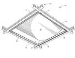
- FIG. 1depicts a lower perspective view of a fluorescent luminaire
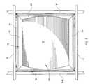
- FIG. 2depicts a bottom view of the fluorescent luminaire of FIG. 1 ;
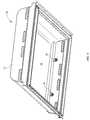
- FIG. 3depicts an upper perspective view of the fluorescent luminaire of FIG. 1 ;
- FIG. 4depicts a lower perspective view of fluorescent luminaire of FIG. 1 with the lens and lens frame removed;
- FIG. 5depicts a rear reflector which may be optionally used with the fluorescent luminaire
- FIG. 6depicts a perspective view of a side frame
- FIG. 7depicts a rear perspective view of an end frame
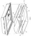
- FIG. 8depicts an exploded perspective view of the luminaire including a lens frame
- FIG. 9depicts a perspective view of the frame pivoted downwardly from the housing
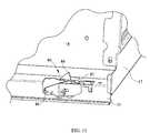
- FIG. 10depicts a detail perspective view of the latching mechanism in an opening position
- FIG. 11depicts a detail perspective view of the latching mechanism in a closed position
- FIG. 12depicts a detail perspective view of the hinge mechanism in a closed position and moving toward an open position
- FIG. 13depicts a flow chart describing methods of assembly for the luminaire.
- the splay frame luminaireutilizes a lens frame within the housing in order to retain a normally relaxed flat lens in a curvilinear shape without requiring the lens be formed in a more expensive manner, such as by extrusion or vacuum forming.
- FIG. 1a lower perspective view of a fluorescent luminaire splay frame assembly 10 is depicted.
- the luminaire assembly 10is positioned within a suspended ceiling 11 defined by longitudinal and latitudinal ceiling members 12 , 14 .
- the terms longitudinal and latitudinalare simply utilized to distinguish between the grid members which extend in perpendicular directions, but should not be considered limiting, wherein the term longitudinal corresponds to the direction a lamp tube extends through the luminaire 10 .
- the ceiling member 12 , 14are depicted as inverted T-grid structures, however slotted T-grid or other ceiling structures may be utilized.
- Each intersection of the longitudinal ceiling members 12 and latitudinal ceiling member 14defines a corner of an opening 19 wherein a troffer body 16 is positioned.
- a troffer body or housingis depicted, the luminaire is not limited to a troffer type luminaire.
- a lens 20is depicted.
- the lens 20is formed of plastic material.
- the lens 20may be formed of polycarbonate, acrylic, or like flexible material.
- the lens 20may have one prismatic surface or two surfaces for controlling dispersion of light.
- the flexible lens 20is formed flat, however the flexibility allows the lens to conform to the shape of the curved edge of the end members 40 .
- the convex shaped lens 20is depicted within the troffer body 16 extending between the side members 30 , 32 and between the end members 40 , 42 .
- FIG. 2a bottom view of the fluorescent luminaire assembly 10 is depicted.
- the assembly 10is bounded by the longitudinal ceiling members 12 and the latitudinal ceiling members 14 .
- the members 12 , 14define an opening wherein the luminaire assembly 10 is positioned.
- the opening defined by the members 12 , 14is square in shape corresponding to a preselected housing 16 shape, for example, 2′ ⁇ 2′ troffer. However, other preselected sizes and shapes may be used such as 1′ ⁇ 4′ and 2′ ⁇ 4′, and the like.
- the lens frame 70is seated within the luminaire housing 16 .
- the lens 20is seated in a frame 70 defined by first and second side frame members 30 , 32 and first and second end members 40 , 42 .
- the innermost surfaces of the members 30 , 32 , 40 , 42are angled with respect to a vertical plane.
- the luminaire assembly 10comprises the housing 16 which has an upper or top wall 18 which curves downwardly at sides of the fixture 10 .
- the troffer body 16further comprises end caps 17 connected to ends of the body.
- the troffer body 16may be formed of metal, for example aluminum, and may be painted at least internally with a reflective white paint or may be polished to a highly reflective mirror like finish.
- a lower edge of the troffer body 16defines an opening for light output.
- the opening in the lower portion of the troffer housing 16is clearly shown in FIG. 4 .
- the lamp sockets 19are positioned at opposite ends of the troffer housing 16 .
- the lamps (not shown) used with the luminaire 10are fluorescent tube lamps, such as T4, T5 or T8 lamps, for example. However, such should not be considered limiting as alternate lamps may be used.
- the exemplary lampsare available from various manufacturers including General Electric, Philips and Sylvania.
- the instant embodimentdepicts two sockets 19 , however various members of sockets may be utilized.
- the inside surface of the troffer bodymay be coated with a reflective surface coating or an internal reflector may be utilized.
- Within the troffer housing 16various components may be positioned but are not shown. For example, an electronic ballast, electronic fusing, or emergency battery packs may be stored in the body 16 .
- a rear reflector 60is depicted.
- the reflector 60is optional for use within the luminaire 10 and may be formed of high purity aluminum or other metal with a polished mirrored surface, or may be coated plastic and may be diffused, such as by painting white, texturing or both.
- the reflector 60is curvilinear wing-shaped, comprising twin parabolic curvilinear portions with notches 64 along two parallel edges. The notches 64 are cut out for the lamp sockets 19 .
- the reflector 60has a first substantially curvilinear portion 66 and a second substantially curvilinear portion 68 which are joined along a fold line 69 .
- the reflector 60is positioned with the troffer housing 16 adjacent the upper wall 18 .
- the axis of the substantially curvilinear portion 66 , 68are parallel to the direction of a lamp extending between the sockets 19 .
- the reflector 60when positioned in the troffer housing 16 , extends between the portions of the upper wall 18 , so that the notches 64 are aligned with the sockets 19 .
- the curvature of the reflector 60provides that the reflector ends are closer to the lens 20 . This has the result of providing substantially even lighting across the lens 20 . With or without the reflector 60 , the photometric performance of the luminaire assembly 10 is desirable for use.
- the reflector 60further comprises fastening apertures 62 along the latitudinal edges of the reflector wings 66 , 68 .
- the fastening apertures 62attach to the troffer body or housing 16 if the optional reflector 60 is utilized.
- the reflector 60comprises two longitudinal edges 61 and two latitudinal edges 63 which define the bounds of the reflector 60 .
- a center fold line 69extends in a longitudinal direction through the center of the reflector 60 and separates the first and second portion 66 , 68 .
- the side frame members 30 , 32are utilized to form the lens frame 70 .
- the side frame member 30is defined by a planar wall 30 a .
- the lower edge of the wallis defined by a bend line 34 from which a leg 36 extends.
- At ends of the wallare first and second upper slots 33 and first and second lower slots 35 .
- the slots 33 , 35receive tabs 43 extending from adjacent end frame members 40 ( FIG. 7 ).
- the slots 33 , 35are aligned at an angle from the vertical rear ends of the side frame members 30 , 32 .
- a shoulder 38is defined wherein the lens 20 is seated.
- the shoulder 38is generally L-shaped, so that the lens 20 is seated within the inside corner of the shoulder 38 .
- the member 30is positioned at an angle form the vertical. This positions the upper leg of the L at a position which is substantially perpendicular to the lens 20 inhibiting the lens 20 from inadvertently disengaging the shoulder 38 .
- the shoulders 38capture the lens 20 .
- apertures 39are spaced at ends so that the side members 30 and end members 40 may be clipped together to maintain a tight connection at lowermost ends of the frame members 30 , 40 .
- the end frame member 40is depicted in perspective view.
- the end framecomprises a planar wall 42 defined by end edges, a lower bend line 45 and an upper curvilinear edge 46 .
- the bend line 45defines an attachment location for a lower leg 47 , which extends between the edges 44 of the end member 40 .
- Extending from the edges 44are upper and lower tabs 43 which correspond to the slots 33 , 35 of the side members 30 .
- the tabs 43extend through the upper and lower slots 33 , 35 and may be folded or crimped in order to retain the side members 30 , 32 to the end members 40 , 42 .
- the leg 47includes fastening apertures 48 similar to the apertures 39 , which are utilized to connect the lower corners of the side members 30 , 32 and end members 40 , 42 .
- the lens frame 70is defined by the pair of end members 40 and pair of side members 30 , wherein the lens 20 may be seated.
- the frame 70is positioned within the troffer housing 16 using a method of hinge and latch devices.
- FIG. 8an exploded perspective view of the reflector 60 and frame 70 is depicted.
- the side members 30 , 32 and end members 40 , 42are assembled to define the frame 70 .
- the lens 20is seated within the curved portion of the end members 40 , and extends from one side member 30 to the opposite side member 30 .
- a horizontal dimension between the shoulders 38is less than the non-flexed horizontal length, lens 20 .
- the lens 20bends and conforms to the curved edge 46 of the end frame members 40 , 42 .
- the lens 20is captured between the shoulders 38 so that the lens 20 is captured between the shoulders 38 inhibiting the lens 20 from inadvertently dislodging from the frame 70 .
- FIGS. 9-12various views of the pivoting lens frame 70 are depicted with respect to the troffer housing 16 .
- the housing 16is depicted in perspective view.
- a hinge 90FIG. 12
- the hinge mechanism 90allows the lens 20 and frame 70 to pivot downwardly from and upwardly to the housing 16 . This allows access to the lamps within the housing 16 as well as the electronic ballast and other electrical components, which may need periodic maintenance or replacing.
- FIG. 10a detail perspective view of a corner of the luminaire 10 is depicted where the end cap 17 meets the upper wall 18 .
- the upper wall 18has a Z-shaped leg 21 extending along a lower edge of the wall between the end caps 17 .
- the legis Z-shaped, alternate structural shapes may be used and therefore such should not be limiting.
- a portion of the leg 21is cut away to depict a latching mechanism 80 .
- An upper surface of the leg 21includes an aperture 82 .
- a latch 84extends through the aperture when the lens frame 70 is in the full upright position for operation. As depicted in FIG.
- the latch 84is pivoted into the aperture 82 , so as to enable the latch to pass through the aperture 82 and so that the lens frame 70 , including lens 20 , may move downwardly, opening the interior portion of the housing 16 .
- Connected to the latch 84is a latch pull 86 .
- the latch pull 86 and latch 84are pivotally connected to some internal structure, so that the latch 84 pivots and extends over an edge of the aperture 82 when the frame 70 is in the fully upright position. Alternatively, the pull 86 may be forced upwardly causing the latch 84 to pivot into the aperture 82 as previously described.
- the latch mechanism 80may be spring biased to a normally closed position or may be actuated manually in one or both directions.
- the latch mechanism 80is shown in the upright position and locked corresponding to the lens frame 70 being in the closed position.
- the latch 84extends over an edge of the aperture 82 , so that the lens frame 70 cannot move downwardly through the aperture 82 .
- the latch pull 86is pushed upwardly, the latch 84 pivots into the aperture 82 and is clear of the edge of aperture 82 as depicted in FIG. 10 .
- a leg 21extends from the upper wall 18 between the end caps 17 .
- the leg 21defines an area for the hinge mechanism 90 .
- the hinge mechanism 90includes a pivot aperture 92 , and a pivot leg 94 having a catch 96 at an end of the leg 94 .
- the leg 94is connected to the lens frame 70 (not shown) so that as the lens frame 70 moves from the closed position to the open position, the pivot leg 94 and catch 96 move from the position shown in solid line to the position shown in broken line.
- the catch 96engages an edge of the pivot aperture 92 , so that the lens frame cannot fall from the leg 21 .
- the latching mechanism 80 and the pivot mechanism 90allow opening and closing of the lens frame 70 to access the interior portion of the luminaire 10 , and allow for locking of the lens frame in an upward position during operation once maintenance inside the luminaire 10 is completed.
- the luminaire housing 16is formed and positioned to receive the lens frame 70 .
- the lens frame 70is formed, and the lens frame 70 is positioned within the luminaire housing 16 .
- a flat lensis positioned within the lens frame.
- the flat lensis positioned by bending the flat lens into a curved configuration, wherein the frame retains the lens in this curved configuration.
- the flat lensmay be positioned in the lens frame prior to positioning of the lens frame within the luminaire housing. In either event, the bending of the flat lens creates a spring force, which retains the lens in position in the lens frame.
- the lens frame 70may be hingedly positioned within the luminaire housing 16 in order to allow opening and closing of the luminaire by lowering of the lens frame 70 and luminaire housing.
- the lens frame 70may also be latched in a closed position within the luminaire housing.
Landscapes
- Engineering & Computer Science (AREA)
- General Engineering & Computer Science (AREA)
- Securing Globes, Refractors, Reflectors Or The Like (AREA)
Abstract
Description
Claims (28)
Priority Applications (1)
| Application Number | Priority Date | Filing Date | Title |
|---|---|---|---|
| US12/140,520US7950833B1 (en) | 2008-06-17 | 2008-06-17 | Splay frame luminaire |
Applications Claiming Priority (1)
| Application Number | Priority Date | Filing Date | Title |
|---|---|---|---|
| US12/140,520US7950833B1 (en) | 2008-06-17 | 2008-06-17 | Splay frame luminaire |
Related Child Applications (1)
| Application Number | Title | Priority Date | Filing Date |
|---|---|---|---|
| US29/321,553ContinuationUSD602187S1 (en) | 2008-06-17 | 2008-07-18 | Luminaire |
Publications (1)
| Publication Number | Publication Date |
|---|---|
| US7950833B1true US7950833B1 (en) | 2011-05-31 |
Family
ID=44064042
Family Applications (1)
| Application Number | Title | Priority Date | Filing Date |
|---|---|---|---|
| US12/140,520Active2029-07-04US7950833B1 (en) | 2008-06-17 | 2008-06-17 | Splay frame luminaire |
Country Status (1)
| Country | Link |
|---|---|
| US (1) | US7950833B1 (en) |
Cited By (9)
| Publication number | Priority date | Publication date | Assignee | Title |
|---|---|---|---|---|
| USD660508S1 (en)* | 2010-03-25 | 2012-05-22 | Lg Innotek Co., Ltd. | Frame for a ceiling light |
| USD661422S1 (en)* | 2011-06-21 | 2012-06-05 | Focal Point, L.L.C. | Lighting fixture |
| USD661423S1 (en)* | 2011-06-21 | 2012-06-05 | Focal Point, L.L.C. | Lighting fixture |
| USD661424S1 (en)* | 2011-06-21 | 2012-06-05 | Focal Point, L.L.C. | Lighting fixture |
| USD679442S1 (en)* | 2012-04-03 | 2013-04-02 | Focal Point, L.L.C. | Lighting fixture |
| US20140146542A1 (en)* | 2012-11-28 | 2014-05-29 | Hubbell Incorporated | Light fixture assembly with pivoting reflector assembly and lens assembly |
| US20140168954A1 (en)* | 2012-12-14 | 2014-06-19 | David Gershaw | Led panel light fixture |
| USD729435S1 (en)* | 2011-12-20 | 2015-05-12 | Oldenburg Group Incorporated | Lighting unit |
| US10190750B1 (en)* | 2015-11-30 | 2019-01-29 | Cooper Technologies Company | Troffer luminaire with an arched lens |
Citations (157)
| Publication number | Priority date | Publication date | Assignee | Title |
|---|---|---|---|---|
| USRE17825E (en) | 1930-10-14 | And william john jarvis | ||
| US2800965A (en) | 1953-07-09 | 1957-07-30 | Benjamin Electric Mfg Co | Light-transmitting plastic sheet panels |
| US2817752A (en) | 1956-01-30 | 1957-12-24 | Lightolier Inc | Lighting system and ceiling panel |
| US2875323A (en) | 1955-01-28 | 1959-02-24 | Mc Graw Edison Co | Outdoor lighting luminaire |
| US2988633A (en) | 1958-09-11 | 1961-06-13 | Sunbeam Lighting Company | Fluorescent ceiling light fixture assembly |
| US2990470A (en) | 1958-03-10 | 1961-06-27 | Sunbeam Lighting Company | Reflecting fluorescent light fixture |
| US2998508A (en) | 1959-05-19 | 1961-08-29 | Sunbeam Lighting Company | Hospital service console and bedlight fixture combination |
| US3052372A (en) | 1960-02-29 | 1962-09-04 | Garcy Company Of Canada Ltd | Hinge structure |
| US3097903A (en) | 1960-06-27 | 1963-07-16 | Esquire Inc | Light fixture |
| US3099403A (en) | 1959-12-10 | 1963-07-30 | Raymond L Strawick | Light fixture |
| US3158327A (en) | 1961-09-15 | 1964-11-24 | Herst Lighting Corp | Fluorescent lighting unit |
| US3246137A (en) | 1966-04-12 | Air diffusing light fixture | ||
| US3299264A (en) | 1964-08-28 | 1967-01-17 | Willis L Lipscomb | End plate for lighting fixtures |
| US3349237A (en) | 1964-12-29 | 1967-10-24 | Sylvania Electric Prod | Strip lighting fixture and connector therefor |
| US3351409A (en) | 1963-06-12 | 1967-11-07 | Irvin H Mcguire | Light diffusion material, method of making and using same |
| US3375361A (en) | 1965-11-10 | 1968-03-26 | Chicago Aerial Ind Inc | Optical illumination system |
| US3384743A (en) | 1965-10-21 | 1968-05-21 | Holophane Co Inc | Desk lamp |
| US3426312A (en) | 1966-03-01 | 1969-02-04 | United Carr Inc | Fluorescent lamp holder |
| US3428799A (en) | 1965-04-12 | 1969-02-18 | Ermanno Bassani | Electricity distributing lines |
| US3483366A (en) | 1966-11-01 | 1969-12-09 | Holophane Co Inc | Luminaire lens |
| US3524050A (en) | 1967-08-08 | 1970-08-11 | Gen Electric | Busway-mounted multiple fixture lighting system with ready access |
| US3532876A (en) | 1963-10-17 | 1970-10-06 | Josef Muller | Light fitting having at least one tubular lamp and a transparent covering of synthetic resin glass with a prismatic surface |
| US3557359A (en) | 1968-01-22 | 1971-01-19 | Electro Systems Inc | Hospital light |
| US3671739A (en)* | 1970-12-08 | 1972-06-20 | Coleman Co | Lamp assembly |
| US3679893A (en) | 1970-09-03 | 1972-07-25 | Sylvan R Schemitz And Associat | Luminaire reflector comprising elliptical and parabolic segments |
| US3685003A (en) | 1970-08-20 | 1972-08-15 | Kenneth E Watt | Fluorescent lampholder |
| US3687055A (en) | 1970-12-15 | 1972-08-29 | Tempmaster Corp | Air vane and fire damper for integrated ceiling systems and the like |
| US3701895A (en) | 1971-06-30 | 1972-10-31 | Thomas Industries Inc | Combined lighting and ventilating fixture |
| US3701898A (en) | 1970-07-29 | 1972-10-31 | Esquire Inc | Light reflector system |
| US3721818A (en) | 1970-05-18 | 1973-03-20 | Ksh Inc | Ceiling mounted luminaire and light-transmitting enclosure therefor |
| US3780286A (en) | 1972-09-20 | 1973-12-18 | Armstrong Cork Co | Curved vault luminaire system |
| US3832540A (en) | 1973-04-13 | 1974-08-27 | Keene Corp | Lamp mounting for high intensity light fixture |
| US3902059A (en) | 1974-02-15 | 1975-08-26 | Esquire Inc | Light reflector system |
| US3909100A (en) | 1974-05-14 | 1975-09-30 | Jr Thomas Hodge | Mounting arrangement for a lamp |
| US3911265A (en) | 1971-11-16 | 1975-10-07 | Esquire Inc | Light fixture |
| US3928757A (en) | 1972-05-26 | 1975-12-23 | Paul Nelson | Spot light fixture |
| US3949214A (en) | 1974-03-05 | 1976-04-06 | The Lucas Electrical Company Limited | Vehicle lamp assembly |
| US3988609A (en) | 1975-03-14 | 1976-10-26 | K-S-H, Inc. | Lighting panel and luminaire using it |
| US4001571A (en) | 1974-07-26 | 1977-01-04 | National Service Industries, Inc. | Lighting system |
| US4054793A (en) | 1973-08-22 | 1977-10-18 | Sylvan R. Shemitz Associates, Inc. | Lighting system |
| US4065667A (en) | 1975-11-13 | 1977-12-27 | Donald L. Goulet | Indirect lighting fixture including improved reflector |
| US4070570A (en) | 1976-06-29 | 1978-01-24 | General Energy Development Corporation | Lighting apparatus |
| US4080978A (en) | 1974-05-26 | 1978-03-28 | Mccabe Francis J | Smoke, fire and air control damper |
| US4128333A (en) | 1977-07-05 | 1978-12-05 | Gte Sylvania Incorporated | Light exposure device including light diffusing and absorbing regions therein |
| US4153929A (en) | 1976-10-20 | 1979-05-08 | Meddev Corporation | Light assembly |
| US4157585A (en)* | 1977-04-14 | 1979-06-05 | Freeman Jerry H | Light fixture |
| USRE30204E (en) | 1975-09-18 | 1980-02-05 | Ruskin Manufacturing Company | Control damper |
| US4198108A (en) | 1978-02-27 | 1980-04-15 | Bassetto Mario F | Socket for fluorescent lamp |
| US4204274A (en) | 1977-06-25 | 1980-05-20 | Willi Luderitz | Wall light fixture, particularly for hospital rooms |
| US4233651A (en) | 1978-03-30 | 1980-11-11 | Keene Corporation | Work area lighting system |
| US4263930A (en) | 1978-04-14 | 1981-04-28 | Prefco Products, Inc. | Diffuser concealable, volume control, heat-responsive, semi-automatic resetting, butterfly damper and operator |
| US4277820A (en) | 1979-04-04 | 1981-07-07 | Bostonian Edward T | Method and apparatus for converting a ceiling light fixture having a plurality of fluorescent lamps into a single lamp, or two lamp, fixture |
| US4288846A (en) | 1979-12-17 | 1981-09-08 | General Electric Company | Floodlight |
| US4300185A (en) | 1979-12-07 | 1981-11-10 | C. W. Cole & Company, Inc. | Light fixture unit for open plan office |
| US4308573A (en) | 1978-06-12 | 1981-12-29 | Esquire, Inc. | Lamp fixture including diffused low angle reflective surfaces |
| US4322783A (en) | 1979-07-18 | 1982-03-30 | Gte Products Corporation | Lamp with improved mount |
| US4323953A (en) | 1980-05-19 | 1982-04-06 | National Service Industries, Inc. | Floodlight |
| US4338653A (en) | 1980-09-24 | 1982-07-06 | Louis Marrero | Versatile fluorescent lighting fixture |
| US4368504A (en) | 1980-09-22 | 1983-01-11 | Toshiba Electric Equipment Corporation | Task lighting apparatus |
| US4388675A (en) | 1980-12-15 | 1983-06-14 | Ian Lewin | Indirect lighting fixture |
| US4415957A (en) | 1981-02-13 | 1983-11-15 | Square D Company | Patient light with hanger and hinge arrangement for removal without tools |
| US4422712A (en) | 1980-10-28 | 1983-12-27 | Siemens Aktiengesellschaft | Housed contact arrangement for a tubular lamp |
| US4432044A (en) | 1981-03-26 | 1984-02-14 | Steelcase Inc. | Task lighting system |
| US4498126A (en) | 1981-06-15 | 1985-02-05 | Wide-Lite International Corporation | Lighting fixture with relamping socket apparatus |
| US4533851A (en) | 1982-10-01 | 1985-08-06 | Patent-Treuhand Gesellschaft | High-pressure electric discharge lamp with interfitting socket and support |
| US4536832A (en) | 1982-07-01 | 1985-08-20 | Altman Stage Lighting Co., Inc. | Replaceable light source assembly |
| US4542947A (en) | 1984-06-04 | 1985-09-24 | Midland-Ross Corporation | Locking assembly for fluorescent lamps |
| US4562515A (en) | 1984-05-23 | 1985-12-31 | Emerson Electric Co. | Calibrated area source task light |
| US4597035A (en) | 1981-06-23 | 1986-06-24 | Horst Lettenmeyer | Lamp structure |
| USD286206S (en) | 1983-08-25 | 1986-10-14 | U.S. Philips Corporation | Lighting fixture |
| US4627498A (en) | 1982-11-12 | 1986-12-09 | Halton Oy | Fuse design for fire limiters or other safety appliances in ventilation installations |
| US4636841A (en) | 1984-05-31 | 1987-01-13 | Rca Corporation | Field comb for luminance separation of NTSC signals |
| US4722039A (en) | 1986-02-06 | 1988-01-26 | Patent Treuhand Gesellschaft Fur Elektrische Gluhlampen Mbh | Shaded beam vehicular discharge-type head lamp |
| US4726781A (en) | 1987-05-05 | 1988-02-23 | Lightolier Incorporated | Connective mechanism for adjacent fluorescent fixtures |
| US4744767A (en) | 1985-01-09 | 1988-05-17 | Brokelmann, Jaeger & Busse Gmbh & Co. | Swingable socket for lamps |
| US4747027A (en) | 1986-05-22 | 1988-05-24 | Friedhelm Hirt Leuchten | Fluorescent lamp light unit |
| US4748547A (en) | 1987-02-06 | 1988-05-31 | Baker Glenn A | Uplight luminaire for achieving uniform illuminance across a ceiling |
| US4760505A (en) | 1987-05-04 | 1988-07-26 | Litecontrol Corporation | Indirect lighting fixture |
| US4796168A (en) | 1986-05-01 | 1989-01-03 | Petersen Jann | Lighting fixture for fluorescent lamps |
| US4803600A (en) | 1987-03-18 | 1989-02-07 | U.S. Philips Corporation | Luminaire for a rod-shaped fluorescent lamp |
| US4842535A (en) | 1988-06-28 | 1989-06-27 | Velke Sr David C | Gas tube electrode connector |
| US4849864A (en) | 1987-09-29 | 1989-07-18 | Louis Forrest | Adjustable lighting assembly |
| US4866583A (en) | 1987-09-01 | 1989-09-12 | Giampaolo Targetti | Sectional structure for mounting spot lights for fitting out of rooms and other |
| US4866584A (en) | 1988-05-27 | 1989-09-12 | Columbia Lighting, Inc. | Indirect luminaire |
| US4876633A (en) | 1986-12-23 | 1989-10-24 | Engel Hartmunt S | Lighting system |
| US4891737A (en) | 1988-12-09 | 1990-01-02 | Thin-Lite Corporation | Quick fit diffuser lens apparatus |
| US4924368A (en) | 1989-01-06 | 1990-05-08 | Duro-Test Corporation | Fluorescent lamp with protective shield |
| US4928209A (en) | 1988-08-31 | 1990-05-22 | Mirrorlite, Inc. | Lighting apparatus |
| US4939627A (en) | 1988-10-20 | 1990-07-03 | Peerless Lighting Corporation | Indirect luminaire having a secondary source induced low brightness lens element |
| US4958687A (en) | 1988-12-15 | 1990-09-25 | Daito Tech Kabushiki Kaisha | Fire damper |
| US4975812A (en) | 1987-05-04 | 1990-12-04 | Litecontrol | Indirect lighting fixture |
| US4980808A (en) | 1989-11-03 | 1990-12-25 | Nicholaos Lilos | Lighting fixture |
| US5006970A (en) | 1989-12-29 | 1991-04-09 | Kenall Manufacturing Company | Interlock electrical socket mount |
| US5038254A (en) | 1990-12-18 | 1991-08-06 | Keene Corporation | Integrated medical light system |
| US5086375A (en) | 1990-12-18 | 1992-02-04 | Keene Corporation | Modular medical light system |
| US5109323A (en) | 1990-11-21 | 1992-04-28 | Thomas Industries, Inc. | Shock resistant lighting fixture |
| US5113328A (en) | 1990-07-10 | 1992-05-12 | Foster Ronald A | Neon tube lighting system, support assembly and extrusion therefor |
| US5124896A (en) | 1991-09-04 | 1992-06-23 | Bentley Raymond B | Fluorescent lamp fixture |
| US5199786A (en) | 1991-06-12 | 1993-04-06 | Mardick Baliozian | Modular element for a lighting device |
| US5226724A (en) | 1992-06-17 | 1993-07-13 | Kanarek Shepard S | Modular, user-installed, surface-mounted, fluorescent lighting system |
| US5272608A (en) | 1992-09-21 | 1993-12-21 | Alkco Manufacturing Company | Hospital room lamp |
| US5272607A (en) | 1991-10-01 | 1993-12-21 | Thorn Licht Gmbh | Lighting fixture |
| US5291379A (en) | 1993-04-01 | 1994-03-01 | Jem Dong Lu | Protective lamp-shade |
| US5301092A (en)* | 1992-04-08 | 1994-04-05 | Anthony's Manufacturing Company, Inc. | Display case with lens lighting system |
| US5343373A (en) | 1993-02-19 | 1994-08-30 | Thomas Industries, Inc. | Suspended up/down light |
| US5371661A (en) | 1992-07-21 | 1994-12-06 | Simpson; Alexander L. | Retro-fit lighting fixture and method of retro-fitting |
| US5436816A (en) | 1994-09-19 | 1995-07-25 | Tivoli Industries, Inc. | Cove lighting apparatus |
| US5440466A (en) | 1994-02-07 | 1995-08-08 | Holophane Lighting, Inc. | Flourescent lighting fixture retrofit unit and method for installing same |
| US5479327A (en) | 1994-10-21 | 1995-12-26 | Chen; Kuo L. | Lighting fixture for aquariums |
| US5493482A (en) | 1994-05-27 | 1996-02-20 | Bowen; Donald A. | Enhanced portable fluorescent work light |
| US5521805A (en) | 1993-08-05 | 1996-05-28 | Lim; Young G. | Fluorescent lamp |
| US5536998A (en) | 1994-11-28 | 1996-07-16 | Royal Lite Manufacturing And Supply Corp. | Fluorescent lamp with a protective assembly |
| US5570947A (en) | 1994-11-08 | 1996-11-05 | Felland; Garold M. | Light fixture |
| US5658066A (en) | 1995-07-20 | 1997-08-19 | Linear Lighting Corp. | Joining system for sectional lighting assembly |
| US5658067A (en) | 1994-12-12 | 1997-08-19 | Munters Corporation | Modular light unit |
| US5702176A (en) | 1994-12-12 | 1997-12-30 | Jji Lighting Group, Inc. | Modular connector device |
| US5716123A (en) | 1996-04-24 | 1998-02-10 | Jji Lighting Group, Inc. | Elongated light tube |
| US5727870A (en) | 1996-05-01 | 1998-03-17 | Ledalite Architectural Products, Inc. | Indirect asymmetric luminaire assembly |
| US5746502A (en) | 1996-10-02 | 1998-05-05 | Huang; Tseng-Tsai | Receptacle structure for fluorescent lamp |
| US5800050A (en) | 1996-03-04 | 1998-09-01 | Nsi Enterprises, Inc. | Downlight and downlight wall wash reflectors |
| US5806967A (en) | 1997-02-12 | 1998-09-15 | Steelcase Inc. | Uplight with removable baffles |
| US5865528A (en) | 1997-03-13 | 1999-02-02 | Precision Architectural Lighting | Indirect light fixture |
| US5884994A (en) | 1996-02-28 | 1999-03-23 | Peerless Lighting Corporation | Direct-indirect luminaire with improved down light control |
| USD409325S (en)* | 1998-07-24 | 1999-05-04 | National Service Industries, Inc. | Recessed wall mounted lighting fixture |
| US5988836A (en) | 1996-07-31 | 1999-11-23 | Swarens; Ralph W. | Recessed indirect fluorescent light fixture with flexible reflector |
| US5988829A (en) | 1997-07-28 | 1999-11-23 | Nsi Enterprises, Inc. | Direct/indirect lighting fixtures |
| US6152573A (en)* | 1998-08-05 | 2000-11-28 | Mitchell; Cary L. | Lens retainer for lighted sign |
| US6155921A (en) | 1999-11-04 | 2000-12-05 | Alcatel Usa Sourcing L.P. | Air ramp |
| US6186642B1 (en) | 1999-03-12 | 2001-02-13 | Steelcase Inc. | On-site fabricated linear ambient lighting system |
| US6193394B1 (en) | 1995-03-09 | 2001-02-27 | Nsi Enterprises, Inc. | Direct-indirect luminaire having improved down light glare control |
| US6203421B1 (en) | 2000-01-29 | 2001-03-20 | Ervin H. Black | Safety ceiling vent |
| US6305816B1 (en) | 1999-03-12 | 2001-10-23 | Steelcase Development Corporation | On-site fabricated linear ambient lighting system |
| US20020003698A1 (en) | 2000-03-20 | 2002-01-10 | Engel Hartmut S. | Lamp cover |
| US6402345B1 (en) | 2001-07-17 | 2002-06-11 | Genlyte Thomas Group Llc | Louver assembly with translucent louver baffles |
| USD460575S1 (en) | 2001-01-19 | 2002-07-16 | Canlyte Inc. | Lighting fixture |
| US6422721B1 (en) | 2000-05-22 | 2002-07-23 | Genlyte Thomas Group Llc | Tube guard system |
| US6505953B1 (en) | 2000-04-06 | 2003-01-14 | Genlyte Thomas Group Llc | Luminaire optical system |
| US6530674B2 (en) | 1998-05-15 | 2003-03-11 | Dean Grierson | Method and apparatus for joining and aligning fixtures |
| US6568830B2 (en) | 2000-09-28 | 2003-05-27 | Canlyte Inc. | End cap joint for linear fixtures |
| USD477891S1 (en) | 2001-02-09 | 2003-07-29 | Zumtobel Staff Gmbh | Ceiling light |
| US6634772B2 (en) | 2000-09-28 | 2003-10-21 | Canlyte Inc. | Linear fixture suspension system |
| US6652113B2 (en)* | 2001-10-01 | 2003-11-25 | Robert J. Tant | Dual mode indirect fluorescent lighting fixture |
| US6655819B2 (en) | 2000-02-14 | 2003-12-02 | Zumtobel Staff Gmbh | Luminaire |
| US6733154B1 (en) | 2002-05-31 | 2004-05-11 | Genlyte Thomas Group Llc | Indirect luminaire |
| US6746325B2 (en) | 2002-02-06 | 2004-06-08 | Genlyte Thomas Group Llc | Heat distorting support clip for air handling luminaire |
| USD496121S1 (en) | 2004-02-03 | 2004-09-14 | Ledalite Architectural Products | Recessed fluorescent luminaire |
| US6817732B1 (en) | 2002-12-05 | 2004-11-16 | Genlyte Thomas Group Llc | Efficiency fluorescent lighting system |
| US6863420B1 (en) | 1999-11-18 | 2005-03-08 | Lid Light Design | Anti-dazzling transparent screen for illuminants |
| US7055982B2 (en) | 2000-09-28 | 2006-06-06 | Canlyte Inc. | Linear fixture assembly |
| US20060198134A1 (en)* | 2005-03-01 | 2006-09-07 | Fowler Wilton L Jr | Fluorescent wall wash luminaire with a sliding mechanism for adjusting lamp position |
| US7204603B1 (en) | 2004-01-29 | 2007-04-17 | Pent Technologies, Inc. | Method of beam and basket construction for linear lighting |
| USD545482S1 (en) | 2004-10-21 | 2007-06-26 | Acuity Brands, Inc. | Light fixture |
| USD545483S1 (en) | 2004-10-21 | 2007-06-26 | Acuity Brands, Inc. | Light fixture |
| USD545992S1 (en) | 2004-10-21 | 2007-07-03 | Acuity Brands, Inc. | Light fixture |
| USD545993S1 (en) | 2004-10-21 | 2007-07-03 | Acuity Brands, Inc. | Light fixture |
| USD556358S1 (en) | 2005-11-22 | 2007-11-27 | Ledalite Architectural Products | Recessed fluorescent luminaire |
| USD561383S1 (en) | 2006-07-20 | 2008-02-05 | Genlyte Thomas Group, Llc | Luminaire lens |
- 2008
- 2008-06-17USUS12/140,520patent/US7950833B1/enactiveActive
Patent Citations (161)
| Publication number | Priority date | Publication date | Assignee | Title |
|---|---|---|---|---|
| US3246137A (en) | 1966-04-12 | Air diffusing light fixture | ||
| USRE17825E (en) | 1930-10-14 | And william john jarvis | ||
| US2800965A (en) | 1953-07-09 | 1957-07-30 | Benjamin Electric Mfg Co | Light-transmitting plastic sheet panels |
| US2875323A (en) | 1955-01-28 | 1959-02-24 | Mc Graw Edison Co | Outdoor lighting luminaire |
| US2817752A (en) | 1956-01-30 | 1957-12-24 | Lightolier Inc | Lighting system and ceiling panel |
| US2990470A (en) | 1958-03-10 | 1961-06-27 | Sunbeam Lighting Company | Reflecting fluorescent light fixture |
| US2988633A (en) | 1958-09-11 | 1961-06-13 | Sunbeam Lighting Company | Fluorescent ceiling light fixture assembly |
| US2998508A (en) | 1959-05-19 | 1961-08-29 | Sunbeam Lighting Company | Hospital service console and bedlight fixture combination |
| US3099403A (en) | 1959-12-10 | 1963-07-30 | Raymond L Strawick | Light fixture |
| US3052372A (en) | 1960-02-29 | 1962-09-04 | Garcy Company Of Canada Ltd | Hinge structure |
| US3097903A (en) | 1960-06-27 | 1963-07-16 | Esquire Inc | Light fixture |
| US3158327A (en) | 1961-09-15 | 1964-11-24 | Herst Lighting Corp | Fluorescent lighting unit |
| US3351409A (en) | 1963-06-12 | 1967-11-07 | Irvin H Mcguire | Light diffusion material, method of making and using same |
| US3532876A (en) | 1963-10-17 | 1970-10-06 | Josef Muller | Light fitting having at least one tubular lamp and a transparent covering of synthetic resin glass with a prismatic surface |
| US3299264A (en) | 1964-08-28 | 1967-01-17 | Willis L Lipscomb | End plate for lighting fixtures |
| US3349237A (en) | 1964-12-29 | 1967-10-24 | Sylvania Electric Prod | Strip lighting fixture and connector therefor |
| US3428799A (en) | 1965-04-12 | 1969-02-18 | Ermanno Bassani | Electricity distributing lines |
| US3384743A (en) | 1965-10-21 | 1968-05-21 | Holophane Co Inc | Desk lamp |
| US3375361A (en) | 1965-11-10 | 1968-03-26 | Chicago Aerial Ind Inc | Optical illumination system |
| US3426312A (en) | 1966-03-01 | 1969-02-04 | United Carr Inc | Fluorescent lamp holder |
| US3483366A (en) | 1966-11-01 | 1969-12-09 | Holophane Co Inc | Luminaire lens |
| US3524050A (en) | 1967-08-08 | 1970-08-11 | Gen Electric | Busway-mounted multiple fixture lighting system with ready access |
| US3557359A (en) | 1968-01-22 | 1971-01-19 | Electro Systems Inc | Hospital light |
| US3721818A (en) | 1970-05-18 | 1973-03-20 | Ksh Inc | Ceiling mounted luminaire and light-transmitting enclosure therefor |
| US3701898A (en) | 1970-07-29 | 1972-10-31 | Esquire Inc | Light reflector system |
| US3685003A (en) | 1970-08-20 | 1972-08-15 | Kenneth E Watt | Fluorescent lampholder |
| US3679893A (en) | 1970-09-03 | 1972-07-25 | Sylvan R Schemitz And Associat | Luminaire reflector comprising elliptical and parabolic segments |
| US3671739A (en)* | 1970-12-08 | 1972-06-20 | Coleman Co | Lamp assembly |
| US3687055A (en) | 1970-12-15 | 1972-08-29 | Tempmaster Corp | Air vane and fire damper for integrated ceiling systems and the like |
| US3701895A (en) | 1971-06-30 | 1972-10-31 | Thomas Industries Inc | Combined lighting and ventilating fixture |
| US3911265A (en) | 1971-11-16 | 1975-10-07 | Esquire Inc | Light fixture |
| US3928757A (en) | 1972-05-26 | 1975-12-23 | Paul Nelson | Spot light fixture |
| US3780286A (en) | 1972-09-20 | 1973-12-18 | Armstrong Cork Co | Curved vault luminaire system |
| US3832540A (en) | 1973-04-13 | 1974-08-27 | Keene Corp | Lamp mounting for high intensity light fixture |
| US4054793A (en) | 1973-08-22 | 1977-10-18 | Sylvan R. Shemitz Associates, Inc. | Lighting system |
| US3902059A (en) | 1974-02-15 | 1975-08-26 | Esquire Inc | Light reflector system |
| US3949214A (en) | 1974-03-05 | 1976-04-06 | The Lucas Electrical Company Limited | Vehicle lamp assembly |
| US3909100A (en) | 1974-05-14 | 1975-09-30 | Jr Thomas Hodge | Mounting arrangement for a lamp |
| US4080978A (en) | 1974-05-26 | 1978-03-28 | Mccabe Francis J | Smoke, fire and air control damper |
| US4001571A (en) | 1974-07-26 | 1977-01-04 | National Service Industries, Inc. | Lighting system |
| US3988609A (en) | 1975-03-14 | 1976-10-26 | K-S-H, Inc. | Lighting panel and luminaire using it |
| USRE30204E (en) | 1975-09-18 | 1980-02-05 | Ruskin Manufacturing Company | Control damper |
| US4065667A (en) | 1975-11-13 | 1977-12-27 | Donald L. Goulet | Indirect lighting fixture including improved reflector |
| US4070570A (en) | 1976-06-29 | 1978-01-24 | General Energy Development Corporation | Lighting apparatus |
| US4153929A (en) | 1976-10-20 | 1979-05-08 | Meddev Corporation | Light assembly |
| US4157585A (en)* | 1977-04-14 | 1979-06-05 | Freeman Jerry H | Light fixture |
| US4204274A (en) | 1977-06-25 | 1980-05-20 | Willi Luderitz | Wall light fixture, particularly for hospital rooms |
| US4128333A (en) | 1977-07-05 | 1978-12-05 | Gte Sylvania Incorporated | Light exposure device including light diffusing and absorbing regions therein |
| US4198108A (en) | 1978-02-27 | 1980-04-15 | Bassetto Mario F | Socket for fluorescent lamp |
| US4233651A (en) | 1978-03-30 | 1980-11-11 | Keene Corporation | Work area lighting system |
| US4263930A (en) | 1978-04-14 | 1981-04-28 | Prefco Products, Inc. | Diffuser concealable, volume control, heat-responsive, semi-automatic resetting, butterfly damper and operator |
| US4308573A (en) | 1978-06-12 | 1981-12-29 | Esquire, Inc. | Lamp fixture including diffused low angle reflective surfaces |
| US4277820A (en) | 1979-04-04 | 1981-07-07 | Bostonian Edward T | Method and apparatus for converting a ceiling light fixture having a plurality of fluorescent lamps into a single lamp, or two lamp, fixture |
| US4322783A (en) | 1979-07-18 | 1982-03-30 | Gte Products Corporation | Lamp with improved mount |
| US4300185A (en) | 1979-12-07 | 1981-11-10 | C. W. Cole & Company, Inc. | Light fixture unit for open plan office |
| US4288846A (en) | 1979-12-17 | 1981-09-08 | General Electric Company | Floodlight |
| US4323953A (en) | 1980-05-19 | 1982-04-06 | National Service Industries, Inc. | Floodlight |
| US4368504A (en) | 1980-09-22 | 1983-01-11 | Toshiba Electric Equipment Corporation | Task lighting apparatus |
| US4338653A (en) | 1980-09-24 | 1982-07-06 | Louis Marrero | Versatile fluorescent lighting fixture |
| US4422712A (en) | 1980-10-28 | 1983-12-27 | Siemens Aktiengesellschaft | Housed contact arrangement for a tubular lamp |
| US4388675A (en) | 1980-12-15 | 1983-06-14 | Ian Lewin | Indirect lighting fixture |
| US4415957A (en) | 1981-02-13 | 1983-11-15 | Square D Company | Patient light with hanger and hinge arrangement for removal without tools |
| US4432044A (en) | 1981-03-26 | 1984-02-14 | Steelcase Inc. | Task lighting system |
| US4498126A (en) | 1981-06-15 | 1985-02-05 | Wide-Lite International Corporation | Lighting fixture with relamping socket apparatus |
| US4597035A (en) | 1981-06-23 | 1986-06-24 | Horst Lettenmeyer | Lamp structure |
| US4536832A (en) | 1982-07-01 | 1985-08-20 | Altman Stage Lighting Co., Inc. | Replaceable light source assembly |
| US4533851A (en) | 1982-10-01 | 1985-08-06 | Patent-Treuhand Gesellschaft | High-pressure electric discharge lamp with interfitting socket and support |
| US4627498A (en) | 1982-11-12 | 1986-12-09 | Halton Oy | Fuse design for fire limiters or other safety appliances in ventilation installations |
| USD286206S (en) | 1983-08-25 | 1986-10-14 | U.S. Philips Corporation | Lighting fixture |
| US4562515A (en) | 1984-05-23 | 1985-12-31 | Emerson Electric Co. | Calibrated area source task light |
| US4636841A (en) | 1984-05-31 | 1987-01-13 | Rca Corporation | Field comb for luminance separation of NTSC signals |
| US4542947A (en) | 1984-06-04 | 1985-09-24 | Midland-Ross Corporation | Locking assembly for fluorescent lamps |
| US4744767A (en) | 1985-01-09 | 1988-05-17 | Brokelmann, Jaeger & Busse Gmbh & Co. | Swingable socket for lamps |
| US4722039A (en) | 1986-02-06 | 1988-01-26 | Patent Treuhand Gesellschaft Fur Elektrische Gluhlampen Mbh | Shaded beam vehicular discharge-type head lamp |
| US4796168A (en) | 1986-05-01 | 1989-01-03 | Petersen Jann | Lighting fixture for fluorescent lamps |
| US4747027A (en) | 1986-05-22 | 1988-05-24 | Friedhelm Hirt Leuchten | Fluorescent lamp light unit |
| US4876633A (en) | 1986-12-23 | 1989-10-24 | Engel Hartmunt S | Lighting system |
| US4933820A (en) | 1986-12-23 | 1990-06-12 | Engel Hartmut S | Lighting system |
| US4748547A (en) | 1987-02-06 | 1988-05-31 | Baker Glenn A | Uplight luminaire for achieving uniform illuminance across a ceiling |
| US4803600A (en) | 1987-03-18 | 1989-02-07 | U.S. Philips Corporation | Luminaire for a rod-shaped fluorescent lamp |
| US4760505A (en) | 1987-05-04 | 1988-07-26 | Litecontrol Corporation | Indirect lighting fixture |
| US4975812A (en) | 1987-05-04 | 1990-12-04 | Litecontrol | Indirect lighting fixture |
| US4726781A (en) | 1987-05-05 | 1988-02-23 | Lightolier Incorporated | Connective mechanism for adjacent fluorescent fixtures |
| US4866583A (en) | 1987-09-01 | 1989-09-12 | Giampaolo Targetti | Sectional structure for mounting spot lights for fitting out of rooms and other |
| US4849864A (en) | 1987-09-29 | 1989-07-18 | Louis Forrest | Adjustable lighting assembly |
| US4866584A (en) | 1988-05-27 | 1989-09-12 | Columbia Lighting, Inc. | Indirect luminaire |
| US4842535A (en) | 1988-06-28 | 1989-06-27 | Velke Sr David C | Gas tube electrode connector |
| US4928209A (en) | 1988-08-31 | 1990-05-22 | Mirrorlite, Inc. | Lighting apparatus |
| US4939627A (en) | 1988-10-20 | 1990-07-03 | Peerless Lighting Corporation | Indirect luminaire having a secondary source induced low brightness lens element |
| US4891737A (en) | 1988-12-09 | 1990-01-02 | Thin-Lite Corporation | Quick fit diffuser lens apparatus |
| US4958687A (en) | 1988-12-15 | 1990-09-25 | Daito Tech Kabushiki Kaisha | Fire damper |
| US4924368A (en) | 1989-01-06 | 1990-05-08 | Duro-Test Corporation | Fluorescent lamp with protective shield |
| US4980808A (en) | 1989-11-03 | 1990-12-25 | Nicholaos Lilos | Lighting fixture |
| US5006970A (en) | 1989-12-29 | 1991-04-09 | Kenall Manufacturing Company | Interlock electrical socket mount |
| US5113328A (en) | 1990-07-10 | 1992-05-12 | Foster Ronald A | Neon tube lighting system, support assembly and extrusion therefor |
| US5109323A (en) | 1990-11-21 | 1992-04-28 | Thomas Industries, Inc. | Shock resistant lighting fixture |
| US5038254A (en) | 1990-12-18 | 1991-08-06 | Keene Corporation | Integrated medical light system |
| US5086375A (en) | 1990-12-18 | 1992-02-04 | Keene Corporation | Modular medical light system |
| US5160193A (en) | 1990-12-18 | 1992-11-03 | Keene Corporation | Modular medical light system |
| US5199786A (en) | 1991-06-12 | 1993-04-06 | Mardick Baliozian | Modular element for a lighting device |
| US5124896A (en) | 1991-09-04 | 1992-06-23 | Bentley Raymond B | Fluorescent lamp fixture |
| US5272607A (en) | 1991-10-01 | 1993-12-21 | Thorn Licht Gmbh | Lighting fixture |
| US5301092A (en)* | 1992-04-08 | 1994-04-05 | Anthony's Manufacturing Company, Inc. | Display case with lens lighting system |
| US5226724A (en) | 1992-06-17 | 1993-07-13 | Kanarek Shepard S | Modular, user-installed, surface-mounted, fluorescent lighting system |
| US5371661A (en) | 1992-07-21 | 1994-12-06 | Simpson; Alexander L. | Retro-fit lighting fixture and method of retro-fitting |
| US5272608A (en) | 1992-09-21 | 1993-12-21 | Alkco Manufacturing Company | Hospital room lamp |
| US5343373A (en) | 1993-02-19 | 1994-08-30 | Thomas Industries, Inc. | Suspended up/down light |
| US5291379A (en) | 1993-04-01 | 1994-03-01 | Jem Dong Lu | Protective lamp-shade |
| US5521805A (en) | 1993-08-05 | 1996-05-28 | Lim; Young G. | Fluorescent lamp |
| US5440466A (en) | 1994-02-07 | 1995-08-08 | Holophane Lighting, Inc. | Flourescent lighting fixture retrofit unit and method for installing same |
| US5493482A (en) | 1994-05-27 | 1996-02-20 | Bowen; Donald A. | Enhanced portable fluorescent work light |
| US5436816A (en) | 1994-09-19 | 1995-07-25 | Tivoli Industries, Inc. | Cove lighting apparatus |
| US5479327A (en) | 1994-10-21 | 1995-12-26 | Chen; Kuo L. | Lighting fixture for aquariums |
| US5570947A (en) | 1994-11-08 | 1996-11-05 | Felland; Garold M. | Light fixture |
| US5536998A (en) | 1994-11-28 | 1996-07-16 | Royal Lite Manufacturing And Supply Corp. | Fluorescent lamp with a protective assembly |
| US5658067A (en) | 1994-12-12 | 1997-08-19 | Munters Corporation | Modular light unit |
| US5702176A (en) | 1994-12-12 | 1997-12-30 | Jji Lighting Group, Inc. | Modular connector device |
| US6247828B1 (en) | 1995-03-09 | 2001-06-19 | Nsi Enterprises, Inc. | Unitary extruded housing for direct-indirect luminaire |
| US6193394B1 (en) | 1995-03-09 | 2001-02-27 | Nsi Enterprises, Inc. | Direct-indirect luminaire having improved down light glare control |
| US5658066A (en) | 1995-07-20 | 1997-08-19 | Linear Lighting Corp. | Joining system for sectional lighting assembly |
| US5884994A (en) | 1996-02-28 | 1999-03-23 | Peerless Lighting Corporation | Direct-indirect luminaire with improved down light control |
| US5800050A (en) | 1996-03-04 | 1998-09-01 | Nsi Enterprises, Inc. | Downlight and downlight wall wash reflectors |
| US5716123A (en) | 1996-04-24 | 1998-02-10 | Jji Lighting Group, Inc. | Elongated light tube |
| US5727870A (en) | 1996-05-01 | 1998-03-17 | Ledalite Architectural Products, Inc. | Indirect asymmetric luminaire assembly |
| US5988836A (en) | 1996-07-31 | 1999-11-23 | Swarens; Ralph W. | Recessed indirect fluorescent light fixture with flexible reflector |
| US5746502A (en) | 1996-10-02 | 1998-05-05 | Huang; Tseng-Tsai | Receptacle structure for fluorescent lamp |
| US5806967A (en) | 1997-02-12 | 1998-09-15 | Steelcase Inc. | Uplight with removable baffles |
| US5865528A (en) | 1997-03-13 | 1999-02-02 | Precision Architectural Lighting | Indirect light fixture |
| US5988829A (en) | 1997-07-28 | 1999-11-23 | Nsi Enterprises, Inc. | Direct/indirect lighting fixtures |
| US6530674B2 (en) | 1998-05-15 | 2003-03-11 | Dean Grierson | Method and apparatus for joining and aligning fixtures |
| USD409325S (en)* | 1998-07-24 | 1999-05-04 | National Service Industries, Inc. | Recessed wall mounted lighting fixture |
| US6152573A (en)* | 1998-08-05 | 2000-11-28 | Mitchell; Cary L. | Lens retainer for lighted sign |
| US6186642B1 (en) | 1999-03-12 | 2001-02-13 | Steelcase Inc. | On-site fabricated linear ambient lighting system |
| US6305816B1 (en) | 1999-03-12 | 2001-10-23 | Steelcase Development Corporation | On-site fabricated linear ambient lighting system |
| US6155921A (en) | 1999-11-04 | 2000-12-05 | Alcatel Usa Sourcing L.P. | Air ramp |
| US6863420B1 (en) | 1999-11-18 | 2005-03-08 | Lid Light Design | Anti-dazzling transparent screen for illuminants |
| US6203421B1 (en) | 2000-01-29 | 2001-03-20 | Ervin H. Black | Safety ceiling vent |
| US6655819B2 (en) | 2000-02-14 | 2003-12-02 | Zumtobel Staff Gmbh | Luminaire |
| US20020003698A1 (en) | 2000-03-20 | 2002-01-10 | Engel Hartmut S. | Lamp cover |
| US6523974B2 (en) | 2000-03-20 | 2003-02-25 | Hartmut S. Engel | Lamp cover |
| US6505953B1 (en) | 2000-04-06 | 2003-01-14 | Genlyte Thomas Group Llc | Luminaire optical system |
| US6422721B1 (en) | 2000-05-22 | 2002-07-23 | Genlyte Thomas Group Llc | Tube guard system |
| US6568830B2 (en) | 2000-09-28 | 2003-05-27 | Canlyte Inc. | End cap joint for linear fixtures |
| US6634772B2 (en) | 2000-09-28 | 2003-10-21 | Canlyte Inc. | Linear fixture suspension system |
| US7055982B2 (en) | 2000-09-28 | 2006-06-06 | Canlyte Inc. | Linear fixture assembly |
| USD460575S1 (en) | 2001-01-19 | 2002-07-16 | Canlyte Inc. | Lighting fixture |
| USD477891S1 (en) | 2001-02-09 | 2003-07-29 | Zumtobel Staff Gmbh | Ceiling light |
| US6402345B1 (en) | 2001-07-17 | 2002-06-11 | Genlyte Thomas Group Llc | Louver assembly with translucent louver baffles |
| US6652113B2 (en)* | 2001-10-01 | 2003-11-25 | Robert J. Tant | Dual mode indirect fluorescent lighting fixture |
| US6746325B2 (en) | 2002-02-06 | 2004-06-08 | Genlyte Thomas Group Llc | Heat distorting support clip for air handling luminaire |
| US6733154B1 (en) | 2002-05-31 | 2004-05-11 | Genlyte Thomas Group Llc | Indirect luminaire |
| US6817732B1 (en) | 2002-12-05 | 2004-11-16 | Genlyte Thomas Group Llc | Efficiency fluorescent lighting system |
| US7204603B1 (en) | 2004-01-29 | 2007-04-17 | Pent Technologies, Inc. | Method of beam and basket construction for linear lighting |
| USD496121S1 (en) | 2004-02-03 | 2004-09-14 | Ledalite Architectural Products | Recessed fluorescent luminaire |
| USD545482S1 (en) | 2004-10-21 | 2007-06-26 | Acuity Brands, Inc. | Light fixture |
| USD545483S1 (en) | 2004-10-21 | 2007-06-26 | Acuity Brands, Inc. | Light fixture |
| USD545992S1 (en) | 2004-10-21 | 2007-07-03 | Acuity Brands, Inc. | Light fixture |
| USD545993S1 (en) | 2004-10-21 | 2007-07-03 | Acuity Brands, Inc. | Light fixture |
| US20060198134A1 (en)* | 2005-03-01 | 2006-09-07 | Fowler Wilton L Jr | Fluorescent wall wash luminaire with a sliding mechanism for adjusting lamp position |
| USD556358S1 (en) | 2005-11-22 | 2007-11-27 | Ledalite Architectural Products | Recessed fluorescent luminaire |
| USD561383S1 (en) | 2006-07-20 | 2008-02-05 | Genlyte Thomas Group, Llc | Luminaire lens |
Cited By (14)
| Publication number | Priority date | Publication date | Assignee | Title |
|---|---|---|---|---|
| USD681872S1 (en) | 2010-03-25 | 2013-05-07 | Lg Innotek Co., Ltd. | Frame for a ceiling light |
| USD660508S1 (en)* | 2010-03-25 | 2012-05-22 | Lg Innotek Co., Ltd. | Frame for a ceiling light |
| USD661422S1 (en)* | 2011-06-21 | 2012-06-05 | Focal Point, L.L.C. | Lighting fixture |
| USD661423S1 (en)* | 2011-06-21 | 2012-06-05 | Focal Point, L.L.C. | Lighting fixture |
| USD661424S1 (en)* | 2011-06-21 | 2012-06-05 | Focal Point, L.L.C. | Lighting fixture |
| USD729435S1 (en)* | 2011-12-20 | 2015-05-12 | Oldenburg Group Incorporated | Lighting unit |
| USD679442S1 (en)* | 2012-04-03 | 2013-04-02 | Focal Point, L.L.C. | Lighting fixture |
| US20140146542A1 (en)* | 2012-11-28 | 2014-05-29 | Hubbell Incorporated | Light fixture assembly with pivoting reflector assembly and lens assembly |
| US9551482B2 (en)* | 2012-11-28 | 2017-01-24 | Hubbell Incorporated | Light fixture assembly with pivoting reflector assembly and lens assembly |
| US20170130938A1 (en)* | 2012-11-28 | 2017-05-11 | Hubbell Incorporated | Light fixture assembly with pivoting reflector assembly and lens assembly |
| US10247389B2 (en)* | 2012-11-28 | 2019-04-02 | Hubbell Incorporated | Light fixture assembly with pivoting reflector assembly and lens assembly |
| US20140168954A1 (en)* | 2012-12-14 | 2014-06-19 | David Gershaw | Led panel light fixture |
| US9182091B2 (en)* | 2012-12-14 | 2015-11-10 | Remphos Technologies Llc | LED panel light fixture |
| US10190750B1 (en)* | 2015-11-30 | 2019-01-29 | Cooper Technologies Company | Troffer luminaire with an arched lens |
Similar Documents
| Publication | Publication Date | Title |
|---|---|---|
| US7950833B1 (en) | Splay frame luminaire | |
| US8556453B1 (en) | Splay frame luminaire | |
| US8042977B1 (en) | Troffer luminaire | |
| US8882298B2 (en) | LED module for light distribution | |
| US7901105B2 (en) | Lighting device and lens assembly | |
| US7297870B1 (en) | Unitized fixture frame and junction box and method of forming same | |
| US7585088B2 (en) | Fluorescent lamp fixture | |
| US6234643B1 (en) | Lay-in/recessed lighting fixture having direct/indirect reflectors | |
| US9874320B2 (en) | Retrofit kit for drop ceiling lighting fixtures | |
| US7980735B1 (en) | Reflector assembly for a recessed luminaire | |
| US6210025B1 (en) | Lensed troffer lighting fixture | |
| US9182091B2 (en) | LED panel light fixture | |
| US20070297181A1 (en) | Louver assembly for a light fixture | |
| US20100277934A1 (en) | Retrofit kit and light assembly for troffer lighting fixtures | |
| US20180231198A1 (en) | Troffer lighting systems and methods for installing the same | |
| KR101281155B1 (en) | Led line bar attachment device | |
| US9028093B2 (en) | Retro-fit luminaire assembly | |
| US20090010007A1 (en) | Recessed Lighting Fixture | |
| US7175300B1 (en) | Side-entry lamping fixture | |
| US20050201075A1 (en) | Lighting fixture | |
| US11867384B2 (en) | Removable positioning of light fixtures | |
| CN215259458U (en) | Panel light | |
| KR100641816B1 (en) | Wiring duct with reflector | |
| CN215259457U (en) | Lamp clip structure | |
| CN218763068U (en) | Seamless concatenation formula contour light |
Legal Events
| Date | Code | Title | Description |
|---|---|---|---|
| AS | Assignment | Owner name:GENLYTE THOMAS GROUP LLC, KENTUCKY Free format text:ASSIGNMENT OF ASSIGNORS INTEREST;ASSIGNORS:CRANE, ROY;FABBRI, WILLIAM;REEL/FRAME:021106/0152 Effective date:20080612 | |
| STCF | Information on status: patent grant | Free format text:PATENTED CASE | |
| FPAY | Fee payment | Year of fee payment:4 | |
| AS | Assignment | Owner name:PHILIPS LIGHTING NORTH AMERICA CORPORATION, NEW JE Free format text:ASSIGNMENT OF ASSIGNORS INTEREST;ASSIGNOR:GENLYTE THOMAS GROUP LLC;REEL/FRAME:041085/0851 Effective date:20160810 | |
| MAFP | Maintenance fee payment | Free format text:PAYMENT OF MAINTENANCE FEE, 8TH YEAR, LARGE ENTITY (ORIGINAL EVENT CODE: M1552); ENTITY STATUS OF PATENT OWNER: LARGE ENTITY Year of fee payment:8 | |
| AS | Assignment | Owner name:SIGNIFY NORTH AMERICA CORPORATION, NETHERLANDS Free format text:CHANGE OF NAME;ASSIGNOR:PHILIPS LIGHTING NORTH AMERICA CORPORATION;REEL/FRAME:050836/0669 Effective date:20190128 | |
| MAFP | Maintenance fee payment | Free format text:PAYMENT OF MAINTENANCE FEE, 12TH YEAR, LARGE ENTITY (ORIGINAL EVENT CODE: M1553); ENTITY STATUS OF PATENT OWNER: LARGE ENTITY Year of fee payment:12 |