US7950585B2 - Protected contactless card - Google Patents
Protected contactless cardDownload PDFInfo
- Publication number
- US7950585B2 US7950585B2US11/741,255US74125507AUS7950585B2US 7950585 B2US7950585 B2US 7950585B2US 74125507 AUS74125507 AUS 74125507AUS 7950585 B2US7950585 B2US 7950585B2
- Authority
- US
- United States
- Prior art keywords
- shield
- tab
- contactless device
- rfid chip
- coupled
- Prior art date
- Legal status (The legal status is an assumption and is not a legal conclusion. Google has not performed a legal analysis and makes no representation as to the accuracy of the status listed.)
- Active, expires
Links
Images


Classifications
- G—PHYSICS
- G06—COMPUTING OR CALCULATING; COUNTING
- G06K—GRAPHICAL DATA READING; PRESENTATION OF DATA; RECORD CARRIERS; HANDLING RECORD CARRIERS
- G06K19/00—Record carriers for use with machines and with at least a part designed to carry digital markings
- G06K19/06—Record carriers for use with machines and with at least a part designed to carry digital markings characterised by the kind of the digital marking, e.g. shape, nature, code
- G06K19/067—Record carriers with conductive marks, printed circuits or semiconductor circuit elements, e.g. credit or identity cards also with resonating or responding marks without active components
- G06K19/07—Record carriers with conductive marks, printed circuits or semiconductor circuit elements, e.g. credit or identity cards also with resonating or responding marks without active components with integrated circuit chips
- G06K19/073—Special arrangements for circuits, e.g. for protecting identification code in memory
- G06K19/07309—Means for preventing undesired reading or writing from or onto record carriers
- G06K19/07318—Means for preventing undesired reading or writing from or onto record carriers by hindering electromagnetic reading or writing
- G06K19/07327—Passive means, e.g. Faraday cages
Definitions
- This disclosurerelates in general to contactless cards and, but not by way of limitation, to physical protection schemes for contactless cards and/or Smartcards amongst other things.
- Protected contactless cardsare perceived by some to have security vulnerabilities. Users may be concerned that someone may surreptitiously steal credit card information with a surveillance device. Users may also be concerned that they may inadvertently pay for another person's transaction by standing too close to a contactless card terminal reader. While these fears and others may be addressed by contactless card manufacturers and system administrators through other means, consumer perceptions of insecurity are a real issue. Accordingly, there is a need for security improvements that can be made to contactless cards that assuage the fears of consumers.
- the present disclosureprovides for a contactless device that includes a presentation instrument body, a shield coupled to the presentation instrument body, a tab moveably coupled with the presentation instrument body between at least a first position and a second position, and a radio frequency identification (RFID) chip coupled to the tab.
- the RFID chipmay be at least partially exposed when the tab is at the first position.
- the RFID chipis at least partially covered by the shield when the tab is at the second position.
- Embodiments of the inventionalso provide for a slideable and rotatable tab.
- the tabmay also include grip edges.
- the devicemay also include a spring coupled to the tab and the presentation instrument body that biases the tab in the second position.
- the presentation instrument bodymay include a magnetic stripe.
- the shieldmay include a material such as a metal mesh, a metal foil and/or a material coated with a metallic ink.
- the devicemay also include an electroluminescence material coupled with the presentation instrument body and electrically coupled with the RFID chip. The electroluminescence material emits light when the RFID chip has been read by an RFID terminal reader.
- the tabmay be circular.
- a contactless devicethat includes a presentation instrument body, an RFID chip coupled with the presentation instrument body, and a moveable shield coupled with the presentation instrument body.
- the shieldis moveable between at least a first position and a second position.
- the RFID chipis at least partially exposed when the moveable shield is at the first position.
- the RFID chipis at least partially covered by the moveable shield when the moveable shield is at the second position.
- Another embodiment of the inventionincludes a contactless device that includes a presentation instrument body, an RFID chip with an RFID inductor coupled with the presentation instrument body, and an electroluminescence material coupled with the presentation instrument body.
- the electroluminescence materialemits light when the RFID chip communicates with an RFID terminal reader.
- the electroluminescence materialis excited by the RFID chip when the chip has been read by an RFID terminal reader.
- the electroluminescence materialmay be a phosphor-based material.
- the electroluminescence materialmay be electrically coupled with the RFID inductor.
- the devicemay include a second RFID inductor coupled electrically with the electroluminescence material.
- Another embodiment of the inventionprovides for a method of personalizing a protected contactless device that comprises an radio-frequency device coupled with a tab that is coupled with the body of a contactless device.
- the methodincludes coupling the radio-frequency device into the tab, recording account information on the radio-frequency chip, coupling a shield with the body of the contactless device, printing the body of the contactless device, and coupling the tab with the body of the contactless device.
- the tabis moveable between at least a first position and a second position. The first position is such that a portion of the tab including the radio-frequency chip is covered by the shield. The second position is such that the portion of the tab including the radio-frequency chip is not covered by the shield.
- the personalizing the radio frequency chipmay include electromagnetically reading an identifier from the radio-frequency chip with a radio-frequency transceiver while the radio-frequency device is within the tab.
- personalizingmay also include electromagnetically writing personalization information onto the radio-frequency chip while the radio-frequency device is within the tab.
- Personalizingmay further include recording an association between the personalization information and the identifier on a storage device.
- a contactless devicein another embodiment, includes a presentation instrument body; an RFID chip coupled with the presentation instrument body, and a shield coupled with the presentation instrument body. At least one of the shield and the RFID is moveable relative each other to at least partially expose the chip.
- FIGS. 1A and 1Bshow a protected contactless card with a slideable tab 140 according to one embodiment of the invention.
- FIGS. 2A and 2Bshow a protected contactless card with a moveable shield according to one embodiment of the invention.
- FIGS. 3A and 3Bshow a protected contactless card with a rotatable tab 140 according to one embodiment of the invention.
- FIGS. 4A and 4Bshow a protected contactless card with a rotatable shield according to one embodiment of the invention.
- FIGS. 5A and 5Bshow a protected contactless card with an electroluminescence indicator according to one embodiment of the invention.
- FIG. 6shows a system for assembling protected contactless card according to one embodiment of the invention.
- FIG. 7shows a method for manufacturing a protected contactless device according to one embodiment of the invention.
- FIG. 8shows a method for manufacturing a protected contactless device according to one embodiment of the invention.
- an “RFID chip”is any microprocessor device configured to exchange data electromagnetically.
- the RFID chipmay include a radio frequency inductor, volatile or non-volatile memory storage, a microprocessor, circuitry logic, and/or an antenna. While it is generally anticipated that such electromagnetic data communications will take place at radio frequencies, this is not a requirement and the electromagnetic data exchanges may take place at any frequency.
- the present disclosureprovides for a protected contactless card.
- the protected contactless cardincludes an RFID chip and a shield.
- the shieldprotects the RFID chip from detection by an RFID reader.
- the shieldmay be moveable relative to the RFID chip and the card body in order to expose the RFID chip and permit access by an RFID reader.
- the shieldmay move laterally or rotate in order to expose the RFID chip.
- the present disclosureprovides for a protected contactless card with a shield and an RFID chip.
- the shieldmay be fixed and the RFID chip may be moveable relative to the shield and the card body in order to expose the RFID chip and permit access by an RFID reader.
- the RFID chipmay move laterally or rotate in order to expose the RFID chip.
- a protected contactless cardthat includes an electroluminescence material.
- the electroluminescence materialilluminates when the RFID chip on the protected contactless card communicates with an RFID terminal.
- the electroluminescence materialmay be electrically coupled with the RF inductor within the RFID chip such that when the RF inductor is activated by an RFID reader the RF inductor powers the electroluminescence material.
- the cardmay include a second RF inductor that is used to power the electroluminescence material.
- the protected contactless presentation instrument 100 -Amay be a credit card, debit card, charge card, access card, stored value card, transportation card, or the like.
- the protected contactless presentation instrument 100 -Aincludes a card body 110 and a shield 120 .
- the card body 110may be constructed of plastic, cardstock, etc.
- the shield 120includes a wire mesh of conductors. The shield may be applied to both sides of the contactless presentation instrument 100 -A.
- the protected contactless presentation instrumentmay 100 -A also include a moveable tab 140 with grip ridges 150 . A portion of the tab 140 is beneath the shield 120 .
- the portion of the tab 140 beneath the shield 120includes an RFID chip 130 (see FIG. 1B ).
- the shield 120 shown in FIG. 1Aincludes a wire mesh
- the shield 120may include a conductor, metal mesh, a metal foil, a metallic ink, etc. Any type of material that creates a Faraday cage that isolates the RFID chip from electromagnetic radiation, such as radio frequency radiation from an RFID terminal reader may be used.
- the shield 120may be constructed out of a metallic substance.
- the shield 120may include a metallic material embedded within other materials.
- the shield 120may include a copper wire mesh embedded in a mylar film. Other materials may also be used, such as plastics and polyesters.
- the tab 140is moveable relative to the card body 110 and the shield 120 .
- the tab 140also includes grip ridges 150 to allow for easier gripping of the tab 140 when a user is sliding the tab 140 .
- the tab 140moves between at least two main positions: an open position and a closed position.
- the tab 140 shown in FIG. 1Ais in the closed position. In this position the RFID chip 130 is shielded from radiation by the shield 120 .
- FIG. 1Bshows the tab 140 in the open position exposing the RFID chip 130 .
- a usersimply slides the tab 140 as shown to expose the RFID chip 130 and complete a transaction.
- the RFID chip 130When the tab 140 is in the closed position, the RFID chip 130 is shielded by the shield 120 and will not communicate with an RF reader.
- the RFID chip 130may be embedded within the tab 140 .
- the card body 110may include guides, groves and/or a slot within which the tab 140 may slide. Guides may also be placed beneath or within the shield 102 for lateral support. The guides, groves, and/or slots may hold the tab 140 from lateral movement as a user slides the tab from position to position.
- the tab 140is coupled to the card body 110 with a spring.
- the springis arranged such that when the tab 140 is in the open position, the spring exerts a force on the tab 140 .
- a usermust apply a counter force on the tab 140 in order to hold the tab 140 in the open position.
- the springpulls the tab 140 into the closed position. With a spring, the tab 140 cannot be opened exposing the RFID chip without user interaction.
- FIG. 2Ashows a protected contactless presentation instrument 100 -B according to another embodiment of the invention.
- the shield 120is moveable.
- FIG. 2Ashows the shield 120 in the closed position shielding the RFID chip 130 .
- FIG. 2Bshows the shield 120 in the open position exposing the RFID chip 130 .
- the shield 120includes a metallic foil and grip ridges.
- the shield 120may be embedded within the card body 110 .
- the card body 110may include grooves within which the shield 120 moves from position to position.
- the shield 120may also include a spring that is coupled to the card body 110 and keeps the shield 120 over the RFID chip 130 when not engaged by a user.
- FIG. 3Ashows a protected contactless presentation instrument 100 -C according to another embodiment of the invention.
- the tab 140 -Cin this embodiment, is circular and includes an RFID chip 130 on one portion of the circular tab 140 -C.
- the circular tab 140 -Cis positioned on the card body 110 in such away that a portion of the circular tab 140 is covered by a shield 120 .
- the circular tab 140 -Cmay be attached to the card body 110 through the center of the circular tab 140 -C so that the circular tab 140 -C may rotate.
- the RFID chip 130 in one positionis completely shielded by the shield 120 and may be exposed by rotating the circular tab 140 about one-hundred eighty degrees to expose the RFID chip 130 as shown in FIG. 3B .
- the circular tab 140 -Cmay include a spring, such as a torsion spring, that applies a force on the circular tab 140 -C to keep the RFID chip 130 shielded by the shield 120 .
- a shieldmay also be placed on the opposite side of the card.
- the shield on the opposite side of the cardmay cover the entire area of the card or may be limited to certain areas on the card.
- the shield on the opposite sidemay be similar to the shield on the side shown in the figure.
- FIG. 4Ashows a protected contactless presentation instrument 100 -D according to another embodiment of the invention.
- the shield 120 -Dis circular, moveable and includes an aperture.
- the RFID chip 130is secured directly to the card body 110 .
- the shield 120 -Dmay be rotated in such a way that the opening is over the RFID chip 130 exposing the RFID chip 130 as shown in FIG. 4B .
- the shield 120 in this embodimentalso includes small bumps 150 to aid a user in rotating the shield 120 .
- the shield 120may also include a spring to keep the shield 120 in position to shield 120 the RFID chip 130 until intervention by a user.
- the protected contactless presentation instruments discussed in embodiments of the inventionmay also include a tab 140 with one or more friction stubs that keep the tab 140 from freely sliding from position to position according to one embodiment of the invention.
- the friction stubsmay also provide resistance between the tab 140 and the card body 110 .
- the tab 140may include a stop. The stop is used to limit the position of the tab 140 in the open position and/or the closed position.
- the stop and friction stubsmay also be included on a moveable shield.
- FIG. 5Ashows a protected contactless presentation instrument 500 with an electroluminescence material 560 and an RFID chip 130 .
- the inductorpowers the RFID chip as well as the electroluminescence material 560 causing the electroluminescence material 560 to illuminate.
- This electroluminescence material 560alerts the user that the card has been activated and that card information may be transmitted from the RFID chip.
- the electroluminescence material 560may include a separate RF inductor that powers the electroluminescence material 560 .
- electroluminescence materialmaybe included on protected contactless cards employing the other embodiments of the invention.
- electroluminescence materialmay be included on protected contactless presentation instruments employing tabs and shields as described above.
- the electroluminescence material 560may include any available electroluminescence material 560 .
- the electroluminescence material 560may include a phosphor based material, Zinc-Sulfide doped with Copper, Zinc-Sulfide doped with Silver, Indium Phosphate, Gallium Arsenide, Gallium Nitride and/or any organic semiconductor.
- the electroluminescence materialmay include phosphor particles having a size between 10-25 microns dispersed within a polymeric binder, such as bisphenol-A epoxy. Other electroluminescence materials may be used.
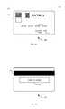
- a protected contactless credit cardmay also include an identification number 504 , a name of the cardholder 508 , and an expiration date 512 .
- the identification numbermay in turn comprise a Bank Identification Number (BIN) and primary account number (PAN) used to identify the issuer and a respective account that in used in support of transactions initiated with the card 500 .
- BINBank Identification Number
- PANprimary account number
- the first six through nine digits of the identification number 504comprise the BIN, but in other embodiments different portions of the identification number 504 comprise the BIN.
- the PANmay similarly by comprised by a subset of the digits of the identification number 504 .
- Other identification numbersmay also be used, such as, identification numbers for loyalty cards or stored value cards.
- FIG. 5Bshows an example of the back of protected contactless credit cards discussed in embodiments of the invention according to one embodiment of the invention.
- the back of these cardsmay include a magnetic stripe 516 and a signature space 520 to record the signature of the cardholders Data are stored on the magnetic stripe in accordance with standard protocols.
- the present disclosureprovides for a protected smartcard with a shield over the active chip of the smartcard.
- a shieldmay protect the chip from damage and/or wear and tear.
- a smartcard shieldmay be configured as in the embodiments shown throughout this disclosure. For instance, the shield may slide like the shield shown in FIGS. 2A and 2B . The shield may rotate as shown in FIGS. 4A and 4B . The smartcard chip may also be placed between a slideable shield that may slide when inserted into automated teller machine for example.
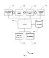
- FIG. 6shows a system for assembling protected contactless card according to one embodiment of the invention.
- the number of protected contactless cards to be assembledmay be large, and, therefore, a batch process may be used.
- a general overview of a system that includes a number of different devices used in coordinating the assemblyis illustrated in the figure.
- the systemincludes a controller 650 that implements methods of the invention and acts to control and coordinate the activities of other components comprised by the system.
- the controller 650is in communication with one or more databases 660 , within which information is stored or information is extracted as described below in coordinating assembly of the protected contactless card s.
- Other components of the systemthat may be provided in communication with and controlled by the controller 650 include an RFID chip optical scanner 670 .
- This deviceis capable of reading and decoding the optical indicia provided on the RFID chips for identification.
- the RFID chip optical scanner 670may comprise a standard bar-code reader.
- An RF transceiver 680provided in communication with the controller 650 permits the transponder within each of the RFID chips to be activated, enabling information to be read from or written to the RF chip within each RFID chip.
- the controller 650may also be provided in communication with one or more logical modules that include instructions for implementing methods of the invention.
- An RFID chip and tab 140 assembly module 610includes instructions for assembling an RFID chip with a tab 140 .
- the RFID chipis on the card itself. In such embodiments this module may include instructions for embedding the RFID chip with the card body.
- a pre-scan module 620includes instructions that permit the system to be used in generating preliminary information that is stored within the database(s) 660 to facilitate later functions.
- a personalization module 630includes instructions to enable personalization information to be encoded on an RFID chip.
- a tab 140 and card assembly module 640may also be included. This module combines the card body and the tab 140 . The module may also prepare a shield and if need attach the shield to the card body. The module may also require making cutouts within portions of the card body and may also include steps for assembling portions of the card body either before, after or while the tab 140 is being attached.
- a quality-assurance modulemay also be included.
- a quality assurance modulemay include instructions that permit checks to be made of individual protected contactless cards to ensure that the recipient identified on the card corresponds to the correct personalization information encoded on the RFID chip within that card. It is generally expected that such quality-assurance processes will be performed on randomly selected samples, with statistical techniques being used to evaluate the reliability of the packaging. In some embodiments, however, the quality-assurance module may be used routinely with every packaged RFID chip as an additional aspect of the process, thereby decreasing even further the risk of misidentification. In some embodiments, particularly after the reliability of the technique has been well established within a particular operational environment, the quality-assurance processes may be omitted.
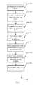
- FIG. 7shows a method for manufacturing a protected contactless device according to one embodiment of the invention. Further personalization methodologies are included in U.S. patent application Ser. No. 10/911,979, which is incorporated herein by reference in its entirety for all purposes.
- the methodbegins by inserting a radio-frequency device with in a tab 140 at block 710 .
- the RFID chip and tab 140 assembly modulemay provide the proper instructions for inserting the RFID chip within the tab 140 .
- the radio-frequency devicemay be inserted as part of a laminating process.
- the radio-frequency devicemay be adhered to a portion of a surface of the tab 140 .
- the radio-frequency devicemay be inserted within a cavity of the tab 140 .
- the identifier on the radio-frequency chipis electromagnetically read at block 720 using the pre-scan module 620 . If an optical code is provided on the RFID chip, this code is scanned with an RFID chip optical scanner and saved. The identifier from the RFID chip may then be extracted by having an RF transceiver activate the chip and return its identifier. Typically, the identifier is provided as a numerical value, but may more generally be provided as any alphanumeric string or other identification sequence that uniquely identifies the chip. A correspondence between the RFID chip optical code and the chip identifier may be recorded in a database. This information thus always allows specification of either the chip identifier or the optical code to be used to identify the other for any of the pre-scanned optical devices.
- Personalization informationis then written onto the radio-frequency chip at block 730 with instructions provided by the personalization module 630 .
- Personalization informationmay first be downloaded from a database.
- Such personalization informationmay generally be any information that is uniquely identified for each of a plurality of recipients of the RFID chips within a batch, but in a particular embodiment comprises magnetic-stripe information used in providing financial-account information for the recipients. Labels may also be printed that identify the recipients, and may include address information that allows the RFID chips to be mailed or otherwise delivered to the recipients.
- An association between the personalization information and the radio frequency device identifieris recorded at block 740 .
- the identifier for the RF chip within the RFID chipis read with an RF transceiver, a procedure that may be performed before or after the RFID chip is inserted within the tab 140 .
- a correspondence between the RFID chip and the personalization information to be encoded on itis recorded in a database(s).
- the database(s)When combined with the pre-scanning information, the database(s) thus includes a record of the personalization information, a record of the identifier of the chip within the RFID chip, and a record of the optical code on the RFID chip.
- the personalization informationis injected with the RF transceiver.
- the personalization informationmay be encrypted to provide security for the information, in which case relevant cryptographic keys may additionally be injected onto the chip with the RF transceiver.
- the cryptographic keysmay comprise data-encryption-standard (“DES”) keys.
- a batch of RFID chipsmay be personalized simultaneously for each RFID chip in the batch.
- the database(s)may contain comprehensive information correlating the RFID chips with the chips they contain and the tab 140 and/or cards within which they are deposited. A check is made at block whether all of the labels within a given batch have been processed in this way.
- the tab 140may then be assembled with the body of the protected contactless card at block 770 by using module 640 .
- the shieldmay also be coupled to the body of the contactless device at block 750 .
- the shieldmay be manufactured in a separate process that may include embedding a wire mesh into a thin plastic material, coating a thin plastic material with a metallic foil or painting a metallic ink on a thin material. Those skilled in the art will recognize other shielding techniques and processes for manufacturing the same.
- the body of the contactless devicemay then embossed at block 760 according to standard protocols.
- the tab 140may then be coupled to the contactless device at block 770 in such a way that the portion of the tab 140 with the RFID chip is shielded by the shield in one position and exposed in a second position.
- FIG. 8shows another method for manufacturing a protected contactless device according to one embodiment of the invention.
- the method of manufactureperforms the same function as shown in FIG. 7 , but in a different order.
- the methodbegins by inserting the RFID chip into the tab at block 710 .
- the shield and the tabare then coupled with the contactless device at blocks 750 , 770 .
- An identifieris then electromagnetically read from the RFID chip at block 720 .
- Personalization informationis then written to the RFID chip at block 730 .
- An association between the identifier and the personalizationis made at block 740 .
- the cardmay then be embossed at block 750 .
- FIGS. 6 , 7 and 8The disclosure in regard to FIGS. 6 , 7 and 8 , is not limited to assembly of protected contactless cards with moveable tab 140 s . Those skilled in the art will recognize simple mortifications that may be made to adapt the assembly process for protected contactless cards with moveable shields.
- RFID devicesmay include passports, identification devices, stored value cards, access cards, key cards, and transportation cards.
- FIG. 7provides a particular sequence that may be followed in particular embodiments of the invention. It should be understood, however, that this particular sequence is merely exemplary and that other sequences may be used in alternative embodiments. Furthermore, the specific identification of steps that are performed is not intended to be limiting; in some embodiments some of the steps for the exemplary embodiments may be omitted while in other embodiments additional steps may be performed.
Landscapes
- Engineering & Computer Science (AREA)
- Physics & Mathematics (AREA)
- Computer Hardware Design (AREA)
- Power Engineering (AREA)
- Electromagnetism (AREA)
- Computer Security & Cryptography (AREA)
- General Engineering & Computer Science (AREA)
- Microelectronics & Electronic Packaging (AREA)
- General Physics & Mathematics (AREA)
- Theoretical Computer Science (AREA)
- Credit Cards Or The Like (AREA)
Abstract
Description
Claims (28)
Priority Applications (2)
| Application Number | Priority Date | Filing Date | Title |
|---|---|---|---|
| US11/741,255US7950585B2 (en) | 2007-04-27 | 2007-04-27 | Protected contactless card |
| PCT/US2008/061589WO2008134520A1 (en) | 2007-04-27 | 2008-04-25 | Protected contactless card |
Applications Claiming Priority (1)
| Application Number | Priority Date | Filing Date | Title |
|---|---|---|---|
| US11/741,255US7950585B2 (en) | 2007-04-27 | 2007-04-27 | Protected contactless card |
Publications (2)
| Publication Number | Publication Date |
|---|---|
| US20080265039A1 US20080265039A1 (en) | 2008-10-30 |
| US7950585B2true US7950585B2 (en) | 2011-05-31 |
Family
ID=39885797
Family Applications (1)
| Application Number | Title | Priority Date | Filing Date |
|---|---|---|---|
| US11/741,255Active2030-02-28US7950585B2 (en) | 2007-04-27 | 2007-04-27 | Protected contactless card |
Country Status (2)
| Country | Link |
|---|---|
| US (1) | US7950585B2 (en) |
| WO (1) | WO2008134520A1 (en) |
Cited By (7)
| Publication number | Priority date | Publication date | Assignee | Title |
|---|---|---|---|---|
| US20110037607A1 (en)* | 2009-08-11 | 2011-02-17 | Oberthur Technologies | Microcircuit Card Comprising a Light-Emitting Diode |
| US20120007718A1 (en)* | 2010-07-09 | 2012-01-12 | Getac Technology Corporation | Radio frequency identification signal receiving device and positioning system using the same |
| US20170091494A1 (en)* | 2015-09-24 | 2017-03-30 | Advanced Digital Broadcast S.A. | System and method for selective access to rfid functionality |
| US10192159B1 (en) | 2018-08-10 | 2019-01-29 | Capital One Services, Llc | Contactless card with transmission blocking element |
| US10628722B2 (en) | 2018-03-23 | 2020-04-21 | International Business Machines Corporation | Method and apparatus to enhance the security of contact-less cards |
| US10755157B2 (en) | 2018-03-23 | 2020-08-25 | International Business Machines Corporation | Advance alert system against copy of contact-less card information |
| US11893439B2 (en) | 2022-05-09 | 2024-02-06 | Capital One Services, Llc | Systems and methods for a mechanical transaction card with privacy features |
Families Citing this family (21)
| Publication number | Priority date | Publication date | Assignee | Title |
|---|---|---|---|---|
| US8820639B2 (en)* | 2006-11-03 | 2014-09-02 | Assa Abloy Ab | Security feature RFID card |
| US10262167B2 (en) | 2008-01-31 | 2019-04-16 | Smartrac Technology Fletcher, Inc. | Detachable radio frequency identification switch tag |
| JP5114263B2 (en)* | 2008-03-26 | 2013-01-09 | 理想科学工業株式会社 | Open container with recording medium |
| IT1401521B1 (en) | 2010-08-11 | 2013-07-26 | St Microelectronics Srl | SAFETY SYSTEM FOR AT LEAST AN INTEGRATED CIRCUIT IC, SAFETY INTEGRATED CIRCUIT BOARD AND SAFETY WIRELESS COMMUNICATION METHOD. |
| US11948035B2 (en) | 2011-05-06 | 2024-04-02 | Neology, Inc. | RFID switch tag |
| US10102685B2 (en) | 2011-05-06 | 2018-10-16 | Neology, Inc. | Self declaring device for a vehicle using restrict traffic lanes |
| WO2012154605A2 (en) | 2011-05-06 | 2012-11-15 | Neology, Inc. | Rfid switch tag |
| US10885418B2 (en) | 2011-05-06 | 2021-01-05 | Neology, Inc. | Detachable radio frequency identification switch tag |
| US8649820B2 (en) | 2011-11-07 | 2014-02-11 | Blackberry Limited | Universal integrated circuit card apparatus and related methods |
| USD703208S1 (en)* | 2012-04-13 | 2014-04-22 | Blackberry Limited | UICC apparatus |
| US8936199B2 (en) | 2012-04-13 | 2015-01-20 | Blackberry Limited | UICC apparatus and related methods |
| USD701864S1 (en)* | 2012-04-23 | 2014-04-01 | Blackberry Limited | UICC apparatus |
| US9135548B2 (en)* | 2012-11-29 | 2015-09-15 | Paypal, Inc. | Portable mechanical switch for selective deactivation of radio frequency identification circuits |
| FR2999865B1 (en)* | 2012-12-19 | 2021-12-17 | Oberthur Technologies | ELECTRONIC ENTITY WITH ANTENNA AND INTEGRATED ELECTROMAGNETIC PROTECTION |
| USD776070S1 (en) | 2014-03-18 | 2017-01-10 | Sony Corporation | Non-contact type data carrier |
| DE102014112287A1 (en)* | 2014-08-27 | 2016-03-03 | Bundesdruckerei Gmbh | communication device |
| DE102014112290A1 (en)* | 2014-08-27 | 2016-03-03 | Bundesdruckerei Gmbh | communication device |
| US11403506B2 (en) | 2015-05-21 | 2022-08-02 | Neology, Inc. | Detachable radio frequency identification switch tag |
| EP3298544B1 (en) | 2015-05-21 | 2022-11-09 | Smartrac Technology Fletcher, Inc. | Multi-frequency radio frequency identification tag |
| JP2017215741A (en)* | 2016-05-31 | 2017-12-07 | 東芝テック株式会社 | RFID tag |
| US10482365B1 (en)* | 2017-11-21 | 2019-11-19 | Wells Fargo Bank, N.A. | Transaction instrument containing metal inclusions |
Citations (13)
| Publication number | Priority date | Publication date | Assignee | Title |
|---|---|---|---|---|
| US5151684A (en) | 1991-04-12 | 1992-09-29 | Johnsen Edward L | Electronic inventory label and security apparatus |
| US5218343A (en) | 1990-02-05 | 1993-06-08 | Anatoli Stobbe | Portable field-programmable detection microchip |
| US5971587A (en) | 1997-08-01 | 1999-10-26 | Kato; Kiroku | Package and mail delivery system |
| US6121544A (en) | 1998-01-15 | 2000-09-19 | Petsinger; Julie Ann | Electromagnetic shield to prevent surreptitious access to contactless smartcards |
| US6257486B1 (en) | 1998-11-23 | 2001-07-10 | Cardis Research & Development Ltd. | Smart card pin system, card, and reader |
| US6275745B1 (en) | 1999-08-11 | 2001-08-14 | Pitney Bowes Inc. | System and method for verifying the delivery of a mailing and the material contained within the mailing |
| US6557758B1 (en) | 1999-10-01 | 2003-05-06 | Moore North America, Inc. | Direct to package printing system with RFID write/read capability |
| US6863219B1 (en)* | 2001-08-17 | 2005-03-08 | Alien Technology Corporation | Apparatuses and methods for forming electronic assemblies |
| US20050099292A1 (en) | 2003-06-17 | 2005-05-12 | United Security Applications Id, Inc. | Electronic security system for monitoring and recording activity and data relating to cargo |
| US20060017570A1 (en) | 2004-07-26 | 2006-01-26 | Moskowitz Paul A | Enabling and disabling a wireless RFID portable transponder |
| US20060028319A1 (en) | 2004-08-04 | 2006-02-09 | First Data Corporation | Radio-frequency-device personalization |
| US20060187055A1 (en)* | 2005-02-07 | 2006-08-24 | Colby Steven M | Containers including radio frequency shielding |
| US20060290501A1 (en) | 2005-06-24 | 2006-12-28 | Visa U.S.A., Inc. | Apparatus and method to electromagnetically shield portable consumer devices |
- 2007
- 2007-04-27USUS11/741,255patent/US7950585B2/enactiveActive
- 2008
- 2008-04-25WOPCT/US2008/061589patent/WO2008134520A1/enactiveApplication Filing
Patent Citations (13)
| Publication number | Priority date | Publication date | Assignee | Title |
|---|---|---|---|---|
| US5218343A (en) | 1990-02-05 | 1993-06-08 | Anatoli Stobbe | Portable field-programmable detection microchip |
| US5151684A (en) | 1991-04-12 | 1992-09-29 | Johnsen Edward L | Electronic inventory label and security apparatus |
| US5971587A (en) | 1997-08-01 | 1999-10-26 | Kato; Kiroku | Package and mail delivery system |
| US6121544A (en) | 1998-01-15 | 2000-09-19 | Petsinger; Julie Ann | Electromagnetic shield to prevent surreptitious access to contactless smartcards |
| US6257486B1 (en) | 1998-11-23 | 2001-07-10 | Cardis Research & Development Ltd. | Smart card pin system, card, and reader |
| US6275745B1 (en) | 1999-08-11 | 2001-08-14 | Pitney Bowes Inc. | System and method for verifying the delivery of a mailing and the material contained within the mailing |
| US6557758B1 (en) | 1999-10-01 | 2003-05-06 | Moore North America, Inc. | Direct to package printing system with RFID write/read capability |
| US6863219B1 (en)* | 2001-08-17 | 2005-03-08 | Alien Technology Corporation | Apparatuses and methods for forming electronic assemblies |
| US20050099292A1 (en) | 2003-06-17 | 2005-05-12 | United Security Applications Id, Inc. | Electronic security system for monitoring and recording activity and data relating to cargo |
| US20060017570A1 (en) | 2004-07-26 | 2006-01-26 | Moskowitz Paul A | Enabling and disabling a wireless RFID portable transponder |
| US20060028319A1 (en) | 2004-08-04 | 2006-02-09 | First Data Corporation | Radio-frequency-device personalization |
| US20060187055A1 (en)* | 2005-02-07 | 2006-08-24 | Colby Steven M | Containers including radio frequency shielding |
| US20060290501A1 (en) | 2005-06-24 | 2006-12-28 | Visa U.S.A., Inc. | Apparatus and method to electromagnetically shield portable consumer devices |
Non-Patent Citations (1)
| Title |
|---|
| PCT International Search Report and Written Opinion mailed Aug. 21, 2008, International U.S. Appl. No. PCT/US2008/061589, 13 pages. |
Cited By (9)
| Publication number | Priority date | Publication date | Assignee | Title |
|---|---|---|---|---|
| US20110037607A1 (en)* | 2009-08-11 | 2011-02-17 | Oberthur Technologies | Microcircuit Card Comprising a Light-Emitting Diode |
| US8869380B2 (en)* | 2009-08-11 | 2014-10-28 | Oberthur Technologies | Microcircuit card comprising a light-emitting diode |
| US20120007718A1 (en)* | 2010-07-09 | 2012-01-12 | Getac Technology Corporation | Radio frequency identification signal receiving device and positioning system using the same |
| US20170091494A1 (en)* | 2015-09-24 | 2017-03-30 | Advanced Digital Broadcast S.A. | System and method for selective access to rfid functionality |
| US9633239B2 (en)* | 2015-09-24 | 2017-04-25 | Advanced Digital Broadcast S.A. | System and method for selective access to RFID functionality |
| US10628722B2 (en) | 2018-03-23 | 2020-04-21 | International Business Machines Corporation | Method and apparatus to enhance the security of contact-less cards |
| US10755157B2 (en) | 2018-03-23 | 2020-08-25 | International Business Machines Corporation | Advance alert system against copy of contact-less card information |
| US10192159B1 (en) | 2018-08-10 | 2019-01-29 | Capital One Services, Llc | Contactless card with transmission blocking element |
| US11893439B2 (en) | 2022-05-09 | 2024-02-06 | Capital One Services, Llc | Systems and methods for a mechanical transaction card with privacy features |
Also Published As
| Publication number | Publication date |
|---|---|
| WO2008134520A1 (en) | 2008-11-06 |
| US20080265039A1 (en) | 2008-10-30 |
Similar Documents
| Publication | Publication Date | Title |
|---|---|---|
| US7950585B2 (en) | Protected contactless card | |
| AU2005332555B2 (en) | Carrying devices for RF tokens | |
| EP1231562B1 (en) | Information input/output unit | |
| AU2007229728B2 (en) | A method for making a secure personal card and its working process | |
| US7156301B1 (en) | Foldable non-traditionally-sized RF transaction card system and method | |
| US7533826B2 (en) | Electronic wallet | |
| EP0905657B1 (en) | Currency note comprising an integrated circuit | |
| US8328106B1 (en) | Convertible transaction card | |
| US20160132761A1 (en) | Payment card having light-emitting diode indicators coordinated with stored payment applications | |
| US20090179744A1 (en) | Radio-frequency-device personalization | |
| EP1610263A1 (en) | Item carrying at least two data storage elements | |
| US20110215155A1 (en) | Variable thickness data card body | |
| CN101253750A (en) | Apparatus and method for electromagnetically shielding portable consumer devices | |
| US20070010213A1 (en) | Secure RFID Packaging | |
| US20080308640A1 (en) | Contactless stand-alone assembly | |
| US20100044442A1 (en) | Proximity identification card with optimally sized antenna and shielded label | |
| WO2010096625A1 (en) | Payment card having acceptance attributes on a single side | |
| US10628722B2 (en) | Method and apparatus to enhance the security of contact-less cards | |
| GB2379739A (en) | Labware with memory storage | |
| EP1675074A1 (en) | System and device for use with a proximity card in a transportation system | |
| Chirico | Smart card programming | |
| KR100794275B1 (en) | Card issuing system and method for issuing a card mounted with IC chip | |
| KR20080072469A (en) | Payment card with password input device | |
| JP2005242872A (en) | Noncontact ic structure with authentication label and reading authentication device | |
| Mackinnon et al. | Smart cards: A case study |
Legal Events
| Date | Code | Title | Description |
|---|---|---|---|
| AS | Assignment | Owner name:FIRST DATA CORPORATION, COLORADO Free format text:ASSIGNMENT OF ASSIGNORS INTEREST;ASSIGNORS:SKOWRONEK, DAN;COCKS, CHRISTOPHER T.;REEL/FRAME:019555/0640 Effective date:20070508 | |
| AS | Assignment | Owner name:CREDIT SUISSE, CAYMAN ISLANDS BRANCH, AS COLLATERA Free format text:SECURITY AGREEMENT;ASSIGNORS:FIRST DATA CORPORATION;CARDSERVICE INTERNATIONAL, INC.;FUNDSXPRESS, INC.;AND OTHERS;REEL/FRAME:020045/0165 Effective date:20071019 | |
| AS | Assignment | Owner name:WELLS FARGO BANK, NATIONAL ASSOCIATION, AS COLLATERAL AGENT, NEW YORK Free format text:SECURITY AGREEMENT;ASSIGNORS:DW HOLDINGS, INC.;FIRST DATA RESOURCES, INC. (K/N/A FIRST DATA RESOURCES, LLC);FUNDSXPRESS FINANCIAL NETWORKS, INC.;AND OTHERS;REEL/FRAME:025368/0183 Effective date:20100820 Owner name:WELLS FARGO BANK, NATIONAL ASSOCIATION, AS COLLATE Free format text:SECURITY AGREEMENT;ASSIGNORS:DW HOLDINGS, INC.;FIRST DATA RESOURCES, INC. (K/N/A FIRST DATA RESOURCES, LLC);FUNDSXPRESS FINANCIAL NETWORKS, INC.;AND OTHERS;REEL/FRAME:025368/0183 Effective date:20100820 | |
| AS | Assignment | Owner name:WELLS FARGO BANK, NATIONAL ASSOCIATION, AS COLLATERAL AGENT, NEW YORK Free format text:SECURITY AGREEMENT;ASSIGNORS:DW HOLDINGS, INC.;FIRST DATA RESOURCES, LLC;FUNDSXPRESS FINANCIAL NETWORKS, INC.;AND OTHERS;REEL/FRAME:025719/0590 Effective date:20101217 Owner name:WELLS FARGO BANK, NATIONAL ASSOCIATION, AS COLLATE Free format text:SECURITY AGREEMENT;ASSIGNORS:DW HOLDINGS, INC.;FIRST DATA RESOURCES, LLC;FUNDSXPRESS FINANCIAL NETWORKS, INC.;AND OTHERS;REEL/FRAME:025719/0590 Effective date:20101217 | |
| STCF | Information on status: patent grant | Free format text:PATENTED CASE | |
| CC | Certificate of correction | ||
| FPAY | Fee payment | Year of fee payment:4 | |
| MAFP | Maintenance fee payment | Free format text:PAYMENT OF MAINTENANCE FEE, 8TH YEAR, LARGE ENTITY (ORIGINAL EVENT CODE: M1552); ENTITY STATUS OF PATENT OWNER: LARGE ENTITY Year of fee payment:8 | |
| AS | Assignment | Owner name:LINKPOINT INTERNATIONAL, INC., CALIFORNIA Free format text:RELEASE BY SECURED PARTY;ASSIGNOR:CREDIT SUISSE AG, CAYMAN ISLANDS BRANCH;REEL/FRAME:049902/0919 Effective date:20190729 Owner name:TASQ TECHNOLOGY, INC., CALIFORNIA Free format text:RELEASE BY SECURED PARTY;ASSIGNOR:CREDIT SUISSE AG, CAYMAN ISLANDS BRANCH;REEL/FRAME:049902/0919 Effective date:20190729 Owner name:FIRST DATA CORPORATION, COLORADO Free format text:RELEASE BY SECURED PARTY;ASSIGNOR:CREDIT SUISSE AG, CAYMAN ISLANDS BRANCH;REEL/FRAME:049902/0919 Effective date:20190729 Owner name:INTELLIGENT RESULTS, INC., COLORADO Free format text:RELEASE BY SECURED PARTY;ASSIGNOR:CREDIT SUISSE AG, CAYMAN ISLANDS BRANCH;REEL/FRAME:049902/0919 Effective date:20190729 Owner name:SIZE TECHNOLOGIES, INC., COLORADO Free format text:RELEASE BY SECURED PARTY;ASSIGNOR:CREDIT SUISSE AG, CAYMAN ISLANDS BRANCH;REEL/FRAME:049902/0919 Effective date:20190729 Owner name:FUNDSXPRESS, INC., TEXAS Free format text:RELEASE BY SECURED PARTY;ASSIGNOR:CREDIT SUISSE AG, CAYMAN ISLANDS BRANCH;REEL/FRAME:049902/0919 Effective date:20190729 Owner name:DW HOLDINGS INC., COLORADO Free format text:RELEASE BY SECURED PARTY;ASSIGNOR:CREDIT SUISSE AG, CAYMAN ISLANDS BRANCH;REEL/FRAME:049902/0919 Effective date:20190729 Owner name:TELECHECK INTERNATIONAL, INC., TEXAS Free format text:RELEASE BY SECURED PARTY;ASSIGNOR:CREDIT SUISSE AG, CAYMAN ISLANDS BRANCH;REEL/FRAME:049902/0919 Effective date:20190729 Owner name:TELECHECK SERVICES, INC., TEXAS Free format text:RELEASE BY SECURED PARTY;ASSIGNOR:CREDIT SUISSE AG, CAYMAN ISLANDS BRANCH;REEL/FRAME:049902/0919 Effective date:20190729 Owner name:CARDSERVICE INTERNATIONAL, INC., CALIFORNIA Free format text:RELEASE BY SECURED PARTY;ASSIGNOR:CREDIT SUISSE AG, CAYMAN ISLANDS BRANCH;REEL/FRAME:049902/0919 Effective date:20190729 Owner name:FIRST DATA RESOURCES, LLC, COLORADO Free format text:RELEASE BY SECURED PARTY;ASSIGNOR:CREDIT SUISSE AG, CAYMAN ISLANDS BRANCH;REEL/FRAME:049902/0919 Effective date:20190729 | |
| AS | Assignment | Owner name:MONEY NETWORK FINANCIAL, LLC, NEW YORK Free format text:TERMINATION AND RELEASE OF SECURITY INTEREST IN PATENT RIGHTS;ASSIGNOR:WELLS FARGO BANK, NATIONAL ASSOCIATION;REEL/FRAME:050090/0060 Effective date:20190729 Owner name:SIZE TECHNOLOGIES, INC., NEW YORK Free format text:TERMINATION AND RELEASE OF SECURITY INTEREST IN PATENT RIGHTS;ASSIGNOR:WELLS FARGO BANK, NATIONAL ASSOCIATION;REEL/FRAME:050090/0060 Effective date:20190729 Owner name:TASQ TECHNOLOGY, INC., NEW YORK Free format text:TERMINATION AND RELEASE OF SECURITY INTEREST IN PATENT RIGHTS;ASSIGNOR:WELLS FARGO BANK, NATIONAL ASSOCIATION;REEL/FRAME:050090/0060 Effective date:20190729 Owner name:INTELLIGENT RESULTS, INC. (K/N/A FIRST DATA SOLUTI Free format text:TERMINATION AND RELEASE OF SECURITY INTEREST IN PATENT RIGHTS;ASSIGNOR:WELLS FARGO BANK, NATIONAL ASSOCIATION;REEL/FRAME:050090/0060 Effective date:20190729 Owner name:FIRST DATA RESOURCES, INC. (K/N/A FIRST DATA RESOU Free format text:TERMINATION AND RELEASE OF SECURITY INTEREST IN PATENT RIGHTS;ASSIGNOR:WELLS FARGO BANK, NATIONAL ASSOCIATION;REEL/FRAME:050090/0060 Effective date:20190729 Owner name:FUNDSXPRESS FINANCIAL NETWORKS, INC., NEW YORK Free format text:TERMINATION AND RELEASE OF SECURITY INTEREST IN PATENT RIGHTS;ASSIGNOR:WELLS FARGO BANK, NATIONAL ASSOCIATION;REEL/FRAME:050090/0060 Effective date:20190729 Owner name:TELECHECK INTERNATIONAL, INC., NEW YORK Free format text:TERMINATION AND RELEASE OF SECURITY INTEREST IN PATENT RIGHTS;ASSIGNOR:WELLS FARGO BANK, NATIONAL ASSOCIATION;REEL/FRAME:050090/0060 Effective date:20190729 Owner name:DW HOLDINGS, INC., NEW YORK Free format text:TERMINATION AND RELEASE OF SECURITY INTEREST IN PATENT RIGHTS;ASSIGNOR:WELLS FARGO BANK, NATIONAL ASSOCIATION;REEL/FRAME:050090/0060 Effective date:20190729 Owner name:FIRST DATA CORPORATION, NEW YORK Free format text:TERMINATION AND RELEASE OF SECURITY INTEREST IN PATENT RIGHTS;ASSIGNOR:WELLS FARGO BANK, NATIONAL ASSOCIATION;REEL/FRAME:050090/0060 Effective date:20190729 Owner name:LINKPOINT INTERNATIONAL, INC., NEW YORK Free format text:TERMINATION AND RELEASE OF SECURITY INTEREST IN PATENT RIGHTS;ASSIGNOR:WELLS FARGO BANK, NATIONAL ASSOCIATION;REEL/FRAME:050090/0060 Effective date:20190729 Owner name:FIRST DATA CORPORATION, NEW YORK Free format text:TERMINATION AND RELEASE OF SECURITY INTEREST IN PATENT RIGHTS;ASSIGNOR:WELLS FARGO BANK, NATIONAL ASSOCIATION;REEL/FRAME:050091/0474 Effective date:20190729 Owner name:DW HOLDINGS, INC., NEW YORK Free format text:TERMINATION AND RELEASE OF SECURITY INTEREST IN PATENT RIGHTS;ASSIGNOR:WELLS FARGO BANK, NATIONAL ASSOCIATION;REEL/FRAME:050091/0474 Effective date:20190729 Owner name:TELECHECK INTERNATIONAL, INC., NEW YORK Free format text:TERMINATION AND RELEASE OF SECURITY INTEREST IN PATENT RIGHTS;ASSIGNOR:WELLS FARGO BANK, NATIONAL ASSOCIATION;REEL/FRAME:050091/0474 Effective date:20190729 Owner name:LINKPOINT INTERNATIONAL, INC., NEW YORK Free format text:TERMINATION AND RELEASE OF SECURITY INTEREST IN PATENT RIGHTS;ASSIGNOR:WELLS FARGO BANK, NATIONAL ASSOCIATION;REEL/FRAME:050091/0474 Effective date:20190729 Owner name:FIRST DATA RESOURCES, LLC, NEW YORK Free format text:TERMINATION AND RELEASE OF SECURITY INTEREST IN PATENT RIGHTS;ASSIGNOR:WELLS FARGO BANK, NATIONAL ASSOCIATION;REEL/FRAME:050091/0474 Effective date:20190729 Owner name:TASQ TECHNOLOGY, INC., NEW YORK Free format text:TERMINATION AND RELEASE OF SECURITY INTEREST IN PATENT RIGHTS;ASSIGNOR:WELLS FARGO BANK, NATIONAL ASSOCIATION;REEL/FRAME:050091/0474 Effective date:20190729 Owner name:SIZE TECHNOLOGIES, INC., NEW YORK Free format text:TERMINATION AND RELEASE OF SECURITY INTEREST IN PATENT RIGHTS;ASSIGNOR:WELLS FARGO BANK, NATIONAL ASSOCIATION;REEL/FRAME:050091/0474 Effective date:20190729 Owner name:FIRST DATA SOLUTIONS, INC., NEW YORK Free format text:TERMINATION AND RELEASE OF SECURITY INTEREST IN PATENT RIGHTS;ASSIGNOR:WELLS FARGO BANK, NATIONAL ASSOCIATION;REEL/FRAME:050091/0474 Effective date:20190729 Owner name:FUNDSXPRESS FINANCIAL NETWORK, INC., NEW YORK Free format text:TERMINATION AND RELEASE OF SECURITY INTEREST IN PATENT RIGHTS;ASSIGNOR:WELLS FARGO BANK, NATIONAL ASSOCIATION;REEL/FRAME:050091/0474 Effective date:20190729 Owner name:MONEY NETWORK FINANCIAL, LLC, NEW YORK Free format text:TERMINATION AND RELEASE OF SECURITY INTEREST IN PATENT RIGHTS;ASSIGNOR:WELLS FARGO BANK, NATIONAL ASSOCIATION;REEL/FRAME:050091/0474 Effective date:20190729 Owner name:FIRST DATA CORPORATION, NEW YORK Free format text:TERMINATION AND RELEASE OF SECURITY INTEREST IN PATENT RIGHTS;ASSIGNOR:WELLS FARGO BANK, NATIONAL ASSOCIATION;REEL/FRAME:050094/0455 Effective date:20190729 Owner name:FIRST DATA RESOURCES, INC. (K/N/A FIRST DATA RESOURCES, LLC), NEW YORK Free format text:TERMINATION AND RELEASE OF SECURITY INTEREST IN PATENT RIGHTS;ASSIGNOR:WELLS FARGO BANK, NATIONAL ASSOCIATION;REEL/FRAME:050090/0060 Effective date:20190729 Owner name:INTELLIGENT RESULTS, INC. (K/N/A FIRST DATA SOLUTIONS, INC.), NEW YORK Free format text:TERMINATION AND RELEASE OF SECURITY INTEREST IN PATENT RIGHTS;ASSIGNOR:WELLS FARGO BANK, NATIONAL ASSOCIATION;REEL/FRAME:050090/0060 Effective date:20190729 | |
| MAFP | Maintenance fee payment | Free format text:PAYMENT OF MAINTENANCE FEE, 12TH YEAR, LARGE ENTITY (ORIGINAL EVENT CODE: M1553); ENTITY STATUS OF PATENT OWNER: LARGE ENTITY Year of fee payment:12 |