US7950038B2 - Transponder tuning and mapping - Google Patents
Transponder tuning and mappingDownload PDFInfo
- Publication number
- US7950038B2 US7950038B2US11/097,479US9747905AUS7950038B2US 7950038 B2US7950038 B2US 7950038B2US 9747905 AUS9747905 AUS 9747905AUS 7950038 B2US7950038 B2US 7950038B2
- Authority
- US
- United States
- Prior art keywords
- signal
- multiswitch
- ird
- interface
- signals
- Prior art date
- Legal status (The legal status is an assumption and is not a legal conclusion. Google has not performed a legal analysis and makes no representation as to the accuracy of the status listed.)
- Active, expires
Links
- 238000013507mappingMethods0.000titledescription3
- 206010065042Immune reconstitution inflammatory syndromeDiseases0.000claimsdescription77
- 208000008498Infantile Refsum diseaseDiseases0.000claimsdescription77
- 230000036593pulmonary vascular resistanceEffects0.000description22
- 238000009434installationMethods0.000description21
- 238000004891communicationMethods0.000description16
- 238000000034methodMethods0.000description13
- 238000010586diagramMethods0.000description12
- 230000010287polarizationEffects0.000description12
- 239000000243solutionSubstances0.000description10
- 238000013519translationMethods0.000description7
- 238000001514detection methodMethods0.000description4
- 238000013459approachMethods0.000description3
- 238000013475authorizationMethods0.000description3
- 230000008569processEffects0.000description3
- 238000011144upstream manufacturingMethods0.000description3
- 239000013078crystalSubstances0.000description2
- 238000013461designMethods0.000description2
- 230000006870functionEffects0.000description2
- 238000012423maintenanceMethods0.000description2
- 238000012986modificationMethods0.000description2
- 230000004048modificationEffects0.000description2
- 230000000737periodic effectEffects0.000description2
- 238000013024troubleshootingMethods0.000description2
- 230000008901benefitEffects0.000description1
- 230000033228biological regulationEffects0.000description1
- 230000005540biological transmissionEffects0.000description1
- 230000000903blocking effectEffects0.000description1
- 239000003990capacitorSubstances0.000description1
- 230000008859changeEffects0.000description1
- 230000001419dependent effectEffects0.000description1
- 230000004069differentiationEffects0.000description1
- 230000000694effectsEffects0.000description1
- 238000001914filtrationMethods0.000description1
- 238000002347injectionMethods0.000description1
- 239000007924injectionSubstances0.000description1
- 238000011900installation processMethods0.000description1
- 230000003993interactionEffects0.000description1
- 238000002955isolationMethods0.000description1
- 238000004519manufacturing processMethods0.000description1
- 230000007246mechanismEffects0.000description1
- 239000000203mixtureSubstances0.000description1
- 230000010355oscillationEffects0.000description1
- 230000010363phase shiftEffects0.000description1
- 230000002265preventionEffects0.000description1
- 238000012545processingMethods0.000description1
- 238000009877renderingMethods0.000description1
- 230000008439repair processEffects0.000description1
- 230000004044responseEffects0.000description1
- 230000011664signalingEffects0.000description1
- 238000013518transcriptionMethods0.000description1
- 230000035897transcriptionEffects0.000description1
Images


Classifications
- H—ELECTRICITY
- H04—ELECTRIC COMMUNICATION TECHNIQUE
- H04N—PICTORIAL COMMUNICATION, e.g. TELEVISION
- H04N7/00—Television systems
- H04N7/10—Adaptations for transmission by electrical cable
- H04N7/102—Circuits therefor, e.g. noise reducers, equalisers, amplifiers
- H04N7/104—Switchers or splitters
- H—ELECTRICITY
- H01—ELECTRIC ELEMENTS
- H01Q—ANTENNAS, i.e. RADIO AERIALS
- H01Q1/00—Details of, or arrangements associated with, antennas
- H01Q1/12—Supports; Mounting means
- H01Q1/125—Means for positioning
- H—ELECTRICITY
- H01—ELECTRIC ELEMENTS
- H01Q—ANTENNAS, i.e. RADIO AERIALS
- H01Q1/00—Details of, or arrangements associated with, antennas
- H01Q1/12—Supports; Mounting means
- H01Q1/22—Supports; Mounting means by structural association with other equipment or articles
- H01Q1/24—Supports; Mounting means by structural association with other equipment or articles with receiving set
- H01Q1/247—Supports; Mounting means by structural association with other equipment or articles with receiving set with frequency mixer, e.g. for direct satellite reception or Doppler radar
- H—ELECTRICITY
- H04—ELECTRIC COMMUNICATION TECHNIQUE
- H04H—BROADCAST COMMUNICATION
- H04H40/00—Arrangements specially adapted for receiving broadcast information
- H04H40/18—Arrangements characterised by circuits or components specially adapted for receiving
- H04H40/27—Arrangements characterised by circuits or components specially adapted for receiving specially adapted for broadcast systems covered by groups H04H20/53 - H04H20/95
- H04H40/90—Arrangements characterised by circuits or components specially adapted for receiving specially adapted for broadcast systems covered by groups H04H20/53 - H04H20/95 specially adapted for satellite broadcast receiving
- H—ELECTRICITY
- H04—ELECTRIC COMMUNICATION TECHNIQUE
- H04N—PICTORIAL COMMUNICATION, e.g. TELEVISION
- H04N7/00—Television systems
- H04N7/20—Adaptations for transmission via a GHz frequency band, e.g. via satellite
Definitions
- the present inventionrelates generally to a satellite receiver system, and in particular, to transponder tuning and mapping within such a network.
- Satellite broadcasting of communications signalshas become commonplace. Satellite distribution of commercial signals for use in television programming currently utilizes multiple feedhorns on a single Outdoor Unit (ODU) which supply signals to up to eight IRDs on separate cables from a multiswitch.
- ODUOutdoor Unit
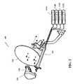
- FIG. 1illustrates a typical satellite television installation of the related art.
- System 100uses signals sent from Satellite A (SatA) 102 , Satellite B (SatB) 104 , and Satellite C (SatC) 106 that are directly broadcast to an Outdoor Unit (ODU) 108 that is typically attached to the outside of a house 110 .
- ODU 108receives these signals and sends the received signals to IRD 112 , which decodes the signals and separates the signals into viewer channels, which are then passed to television 114 for viewing by a user.
- IRD 112decodes the signals and separates the signals into viewer channels, which are then passed to television 114 for viewing by a user.
- Satellite uplink signals 116are transmitted by one or more uplink facilities 118 to the satellites 102 - 104 that are typically in geosynchronous orbit. Satellites 102 - 106 amplify and rebroadcast the uplink signals 116 , through transponders located on the satellite, as downlink signals 120 . Depending on the satellite 102 - 106 antenna pattern, the downlink signals 120 are directed towards geographic areas for reception by the ODU 108 .
- Each satellite 102 - 106broadcasts downlink signals 120 in typically thirty-two (32) different frequencies, which are licensed to various users for broadcasting of programming, which can be audio, video, or data signals, or any combination. These signals are typically located in the Ku-band of frequencies, i.e., 11-18 GHz. Future satellites will likely broadcast in the Ka-band of frequencies, i.e., 18-40 GHz, but typically 20-30 GHz.
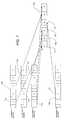
- FIG. 2illustrates a typical ODU of the related art.
- ODU 108typically uses reflector dish 122 and feedhorn assembly 124 to receive and direct downlink signals 120 onto feedhorn assembly 124 .
- Reflector dish 122 and feedhorn assembly 124are typically mounted on bracket 126 and attached to a structure for stable mounting.
- Feedhorn assembly 124typically comprises one or more Low Noise Block converters 128 , which are connected via wires or coaxial cables to a multiswitch, which can be located within feedhorn assembly 124 , elsewhere on the ODU 108 , or within house 110 .
- LNBstypically downconvert the FSS-band, Ku-band, and Ka-band downlink signals 120 into frequencies that are easily transmitted by wire or cable, which are typically in the L-band of frequencies, which typically ranges from 950 MHz to 2150 MHz. This downconversion makes it possible to distribute the signals within a home using standard coaxial cables.
- the multiswitchenables system 100 to selectively switch the signals from SatA 102 , SatB 104 , and SatC 106 , and deliver these signals via cables 124 to each of the IRDs 112 A-D located within house 110 .
- the multiswitchis a five-input, four-output (5 ⁇ 4) multiswitch, where two inputs to the multiswitch are from SatA 102 , one input to the multiswitch is from SatB 104 , and one input to the multiswitch is a combined input from SatB 104 and SatC 106 .
- the multiswitchcan be other sizes, such as a 6 ⁇ 8 multiswitch, if desired.
- SatB 104typically delivers local programming to specified geographic areas, but can also deliver other programming as desired.
- each broadcast frequencyis further divided into polarizations.
- Each LNB 128can only receive one polarization at time, so by aligning polarizations between the downlink polarization and the LNB 128 polarization, downlink signals 120 can be selectively filtered out from travelling through the system 100 to each IRD 112 A-D.
- IRDs 112 A-Dcurrently use a one-way communications system to control the multiswitch.
- Each IRD 112 A-Dhas a dedicated cable 124 connected directly to the multiswitch, and each IRD independently places a voltage and signal combination on the dedicated cable to program the multiswitch.
- IRD 112 Amay wish to view a signal that is provided by SatA 102 .
- IRD 112 Asends a voltage/tone signal on the dedicated cable back to the multiswitch, and the multiswitch delivers the SatA 102 signal to IRD 112 A on dedicated cable 124 .
- IRD 112 Bindependently controls the output port that IRD 112 B is coupled to, and thus may deliver a different voltage/tone signal to the multiswitch.
- the voltage/tone signaltypically comprises a 13 Volts DC (VDC) or 18 VDC signal, with or without a 22 kHz tone superimposed on the DC signal.
- VDC13 Volts DC
- 18 VDC signal13VDC without the 22 kHz tone would select one port
- 13VDC with the 22 kHz tonewould select another port of the multiswitch, etc.
- modulated tonetypically a 22 kHz tone, where the modulation schema can select one of any number of inputs based on the modulation scheme.
- outputs of the LNBs 128 present in the ODU 108can be combined, or “stacked,” depending on the ODU 108 design.
- the stacking of the LNB 128 outputsoccurs after the LNB has received and downconverted the input signal. This allows for multiple polarizations, one from each satellite 102 - 106 , to pass through each LNB 128 . So one LNB 128 can, for example, receive the Left Hand Circular Polarization (LHCP) signals from SatC 102 and SatB 104 , while another LNB receives the Right Hand Circular Polarization (RHCP) signals from SatB 104 , which allows for fewer wires or cables between the LNBs 128 and the multiswitch.
- LHCPLeft Hand Circular Polarization
- SatB 104receives the Right Hand Circular Polarization
- the Ka-band of downlink signals 120will be further divided into two bands, an upper band of frequencies called the “A” band and a lower band of frequencies called the “B” band.
- each LNB 128can deliver the signals from the Ku-band, the A band Ka-band, and the B band Ka-band signals for a given polarization to the multiswitch.
- current IRD 112 and system 100 designscannot tune across this entire frequency band, which limits the usefulness of this stacking feature.
- each LNB 128typically delivers 48 transponders of information to the multiswitch, but some LNBs 128 can deliver more or less in blocks of various size.
- the multiswitchallows each output of the multiswitch to receive every LNB 128 signal (which is an input to the multiswitch) without filtering or modifying that information, which allows for each IRD 112 to receive more data.
- current IRDs 112cannot use the information in some of the proposed frequencies used for downlink signals 120 , thus rendering useless the information transmitted in those downlink signals 120 .
- all inputs to the multiswitchare utilized by the current satellite 102 - 106 configuration, which prevents upgrades to the system 100 for additional satellite downlink signals 120 to be processed by the IRD 112 .
- adding another IRD 112 to a house 110requires a cabling run back to the ODU 108 .
- Such limitations on the related artmake it difficult and expensive to add new features, such as additional channels, high-definition programming, additional satellite delivery systems, etc., or to add new IRD 112 units to a given house 110 .
- An apparatus in accordance with the present inventioncomprises a receive antenna, including at least one low noise block amplifier (LNB); and a module, coupled to and proximate the receive antenna, the module comprising a multiswitch, coupled to the LNB, for directing the satellite signal received by the LNB to an output of the multiswitch, at least one tuner, coupled to the output of the multiswitch, for tuning to a specific portion of the satellite signal, the specific portion of the satellite signal selected based on commands received from a new Integrated Receiver Decoder (IRD), at least one demodulator, coupled to the at least one tuner, for demodulating the specific portion of the signal into a plurality of demodulated signals, and an interface for delivering a specific demodulated signal to the new IRD, wherein the specific demodulated signal is selected based on the commands received from the new IRD, and the
- IRDIntegrated Receiver Decoder
- the systemoptionally further comprises a way for the commands and the specific demodulated signal to be carried on a single connection between the at least one IRD and the interface, a plurality of new IRDs, wherein each IRD has a unique private channel number, and the interface delivers a combined signal comprising a plurality of specific demodulated signals, each demodulated signal selected based on commands received from each of the plurality of new IRDs, a controller, coupled to the interface, for controlling signal flow between the interface and the plurality of IRDs, and a second output of the multiswitch, wherein the second output is a legacy output that commands the multiswitch via a cable other than the single connection.
- the systemcan further include a network tuner, coupled between the multiswitch and the interface, wherein the network tuner is controlled by a service provider, allows for the controller to monitor signal strengths of the specific demodulated signals, and can also comprise an automatic gain controller, coupled between the multiswitch and the interface, for controlling the signal strengths of the specific demodulated signals.
- a network tunercoupled between the multiswitch and the interface, wherein the network tuner is controlled by a service provider, allows for the controller to monitor signal strengths of the specific demodulated signals
- an automatic gain controllercoupled between the multiswitch and the interface, for controlling the signal strengths of the specific demodulated signals.
- the modulecan also refuse commands from an IRD that requires a signals strength of the specific demodulated signal associated with that IRD that is larger than a predetermined amount.
- Another embodiment of the present inventioncomprises a multiswitch, for selectively directing the satellite video signals based on which satellite of the plurality of satellites broadcast the satellite video signal to an output of the multiswitch, at least one tuner, coupled to the output of the multiswitch, for tuning to a specific portion of the satellite video signal, the specific portion of the satellite signal selected based on a command received from the IRD, at least one demodulator, coupled to the at least one tuner in a respective fashion, for demodulating the specific portion of the signal into a plurality of demodulated signals, and an interface for delivering a specific demodulated signal to the IRD, wherein the specific demodulated signal is mapped to a new address based on a private channel number associated with the IRD.
- Optional items for this embodimentinclude an automatic gain controller, coupled between the multiswitch and the interface, for controlling the signal strengths of the specific demodulated signals, the specific demodulated signal being selected based on the command received from the IRD, a network tuner, coupled between the multiswitch and the interface, wherein the network tuner cannot be controlled by the IRD, a controller, coupled to the interface, for controlling signal flow between the interface and the plurality of IRDs, a second output of the multiswitch, wherein the second output is an output that commands the multiswitch via a connection other than the interface, the interface having an output comprising a combined signal, which comprises a plurality of individual signals, a first individual signal comprising an output of the network tuner, and additional individual signals comprising at least one specific demodulated signal, and the IRD receiving the entire combined signal and tunes to the individual signals based on the new address associated with the individual signal.
- an automatic gain controllercoupled between the multiswitch and the interface, for controlling the signal strengths of the specific demodulated
- Another embodiment of the present inventioncomprises a multiswitch, for selectively directing the satellite video signals based on which satellite of the plurality of satellites broadcast the satellite video signal to an output of the multiswitch, at least one tuner, coupled to the output of the multiswitch, for tuning to a specific portion of the satellite video signal, the specific portion of the satellite signal selected based on a command received from the IRD, and an interface for delivering the specific portion of the satellite signal to the IRD, wherein the portion is mapped to a new address based on a private channel number associated with the IRD.
- This embodimentcan also include the interface being a network interface, and an output of the interface being a combined signal, and the IRD selects a portion of the satellite signal based on the private channel number.
- FIG. 1illustrates a typical satellite television installation of the related art
- FIG. 2illustrates a typical ODU of the related art
- FIG. 3illustrates a system diagram of the present invention
- FIG. 4is a detailed block diagram of the frequency translation module of the present invention.
- FIG. 4Aillustrates a digital FTM solution in accordance with the present invention
- FIG. 5illustrates a typical home installation of the related art
- FIG. 6illustrates the general communication schema used within the present invention
- FIG. 7illustrates a typical remapped signal in accordance with the present invention
- FIG. 8Aillustrates an alternative block diagram of the frequency translation module of the present invention
- FIG. 8Billustrates a Shift Keyed Controller of the present invention
- FIG. 9illustrates a block diagram of a power injector in accordance with the present invention.
- FIG. 10is a block diagram of the power injector in accordance with the present invention.
- FIGS. 11 and 12illustrate signal splitters in accordance with the present invention.
- the HDTV signalscan be broadcast from the existing satellite constellation, or broadcast from the additional satellite(s) that will be placed in geosynchronous orbit.
- the orbital locations of the satellitesare fixed by regulation as being separated by nine degrees, so, for example, there is a satellite at 101 degrees West Longitude (WL), SatA 102 ; another satellite at 110 degrees WL, SatC 106 ; and another satellite at 119 degrees WL, SatB 104 .
- Satellitesmay be at other orbital slots, e.g., 72.5 degrees, 95 degrees, 99 degrees, and 103 degrees, and other orbital slots, without departing from the scope of the present invention.
- the satellitesare typically referred to by their orbital location, e.g., SatA 102 , the satellite at 101 WL, is typically referred to as “101.” Additional orbital slots, with one or more satellites per slot, are presently contemplated.
- the present inventionallows currently installed systems to continue receiving currently broadcast satellite signals, as well as allowing for expansion of additional signal reception and usage. Further, the present invention allows for the use of pre-existing cabling within a given home such that the signal distribution within a home can be done without large new cable runs from the external antenna to individual set-top boxes.
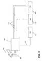
- FIG. 3illustrates a system diagram of the present invention.
- ODU 108is coupled to Frequency Translation Module (FTM) 300 .
- FTM 300is coupled to power injector 302 .
- FTM 300is able to directly support currently installed IRD 112 directly as shown via cable 124 , as described with respect to FIGS. 1 and 2 .
- the present inventionis also able to support new IRDs 308 , via a network of signal splitters 304 and 306 , and power injector 302 .
- New IRDs 308are able to perform two-way communication with FTM 300 , which assists IRDs 308 in the delivery of custom signals on private IRD selected channels via a single cable 310 .
- Each of the splitters 304 and 306can, in some installations, have intelligence in allowing messages to be sent from each IRD 308 to FTM 300 , and back from FTM 300 to IRDs 308 , where the intelligent or smart signal splitters 304 and 306 control access to the FTM 300 .
- the two-way communication between IRDs 308 and FTM 300can take place via cable 310 , or via other wiring, such as power distribution lines or phone lines that are present within house 110 .
- one or more possible communications schemacan take place between IRD 308 and FTM 300 such that existing wiring in a house 110 can be used to deliver satellite signals and control signals between IRD 308 and FTM 300 , such as an RF FSK approach or an RF ASK approach discussed herein.
- Such schemainclude, but are not limited to, a digital FTM solution, a remultiplexed (remux) FTM solution, an analog FTM solution, and a hybrid FTM solution.
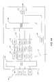
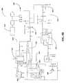
- FIG. 4is a detailed block diagram of the frequency translation module of the present invention.
- FTM 300shows multiple LNBs 128 coupled to multiswitch 400 .
- Multiswitch 400supports current IRDs 112 via cable 124 .
- Multiple cables 124are shown to illustrate that more than one current IRD 112 can be supported.
- the number of current IRDs 112 that can be supported by FTM 300can be more than two if desired without departing from the scope of the present invention.
- Multiswitch 400has several outputs coupled to individual tuners 402 .
- Each tuner 402can access any of the LNB 128 signals depending on the control signals sent to each tuner 402 .
- the output of each tuner 402is a selected transponder signal that is present in one of the downlink signals 120 . The method of selection of the transponder will be discussed in more detail below.
- each signalis then demodulated by individual demodulators 404 , and then demultiplexed by demultiplexers 406 .
- the outputs of each of the demultiplexers 406are a specific packet of information present on a given transponder for a given satellite 102 - 106 . These packets may have similar nomenclature or identification numbers associated with them, and, as such, to prevent the IRDs 308 from misinterpreting which packet of information to view, each packet of information is given a new identification code. This process is called re-mapping, and is performed by the SCID remappers 408 .
- the outputs of each of the SCID remappers 408are uniquely named packets of information that have been stripped from various transponders on various satellites 102 - 106 .
- remapped signalsare then multiplexed together by mux 410 , and remodulated via modulator 412 .
- An amplifier 414then amplifies this modulated signal and sends it out via cable 310 .
- the signal present on cable 310is generated by requests from the individual IRDs 308 and controlled by controller 416 .
- Controller 416receives the requests from IRDs 308 and controls tuners 402 in such a fashion to deliver only the selected transponder data (in an Analog FTM schema) or individualized packets of interest within a given transponder to all of the IRDs 308 in a given house 110 .
- each of the cables 124delivers sixteen (16) transponders, all at one polarization, from a satellite selected by IRD 112 .
- Each IRD 112is free to select any polarization and any satellite coupled to multiswitch 400 .
- the control of the multiswitch 400 by current IRDs 112along with limitations on the tuner bandwidth available within the IRDs 112 , provide difficult obstacles for distribution of signals within the current system 100 .
- the system of the present inventioncan provide a smaller subset of the available downlink signal 120 bandwidth to the input of the IRD 308 , making it easier for the IRD 308 to tune to a given viewer channel of interest. In essence, it adds additional stages of downlink signal 120 selection upstream of the IRD 308 , which provides additional flexibility and dynamic customization of the signal that is actually delivered to individual IRDs 308 .
- the FTM 300can tune to these signals using tuners 402 , and remodulate the specific transponder signals of interest within the Ka-band downlink signals 120 to individual IRDs 308 on cable 310 .
- the tuners present within each IRD 308are not required to tune over a large frequency range, and even though a larger frequency range is being transmitted via downlink signals 120 , the IRDs 308 can accept these signals via the frequency translation performed by FTM 300 .
- chain 418which comprises a tuner 402 , demodulator 404 , demultiplexer 406 , and SCID remapper 408 , is dedicated to a specific IRD 308 .
- each chain 418is tuned to a different downlink signal 120 , or to a different signal within a downlink signal 120 , to provide the given IRD 308 the channel of interest for that IRD 308 on the private channel.
- chain 418is shown with tuner 402 , demodulator 404 , demultiplexer 406 , and SCID remapper 408 , other combinations of functions or circuits can be used within the chain 418 to produce similar results without departing from the scope of the present invention.
- FIG. 4Aillustrates a digital FTM solution in accordance with the present invention.
- the digital FTM solutionsues a network interface 420 which can use standard network protocols to communicate between the FTM 300 and the IRD 308 , much like the interface between two computers in a network. Since the tuner 402 , demodulator 404 , and demultiplexer 406 have separated out the majority of the unnecessary signals from the downlink signal 120 , the signals from each chain 422 can be placed sequentially or in an encoded fashion through network interface 420 , and transmitted to each of the IRDs 308 coupled to FTM 300 . Controller 416 acts as a local processor to control the network traffic. Operation of the system is similar to that of the system described in FIG.
- each IRD 308 in a digital FTM solution as shown in FIG. 4Ano longer requires a tuner.
- the network interface 420is substantially repeated in each IRD 308 , and the digital information is transcribed into video format much like video transcription on computer networks.
- FIG. 5illustrates a typical home installation of the related art.
- ODU 108has cables 500 that couple LNBs 108 to multiswitch 502 .
- Multiswitch 502is used to distribute the satellite downlink signals 120 received at ODU 108 throughout house 110 .
- Multiswitch 502allows each IRD 112 , or Personal Video Recorder (PVR) 504 , access to the satellite downlink signals 120 via cables 124 .
- PVRPersonal Video Recorder
- Each tuner present in the systemmust have a dedicated cable 124 that runs from the IRD 112 or PVR 504 all the way to multiswitch 502 .
- Other configurationscan be envisioned, such as an IRD 112 with multiple inputs, PVRs 504 with more than two tuners, network tuner applications, etc., without departing from the scope of the present invention.
- Standard configurations of multiswitches 502accommodate the number of IRDs 112 and PVRs 504 present within a given installation or house 110 . These can be, for example, a 4 ⁇ 8 multiswitch, where four inputs from ODU 108 are distributed into eight outputs, where each output can deliver signals to the IRDs 112 and PVRs 504 . Although all multiswitches 502 have internal elements requiring power, the power can be drawn from the IRDs 112 , or from an external source.
- the multiswitch 502in current installations, is non-discriminatory; it provides all of the data present within a given polarization of a downlink signal 120 to the tuners within the IRDs 112 and PVRs 504 . This is sixteen times the amount of bandwidth necessary to drive the individual tuners within the IRDs 112 and PVRs 504 .
- FIG. 6illustrates the general communication schema used within the present invention.
- the present inventionsends communications in two directions between IRD 308 and FTM 300 .
- IRD 308After installation, IRD 308 sends a private IRD channel request 600 to the FTM 300 .
- This requestcan be sent when the IRD 308 is powered on, or at any time the IRD 308 is on and needs a new private channel. Such occurrences may take place after a periodic time, or during troubleshooting of the system, or at other desired times.
- FTM 300assigns an IRD private channel to the IRD 308 , and dedicates one of the chains 418 or 422 including tuner 402 , etc. to a specific IRD 308 .
- the channel information and decoding schema for the IRD private channel for each IRD 308is sent back as acknowledgement 602 from FTM 300 to IRD 308 .
- the specific data request 604is sent from IRD 308 to FTM 300 .
- FTM 300determines which downlink signal 120 has the requested data, uses the tuner 402 to tune to the downlink signal 120 of interest, demodulates and demultiplexes the downlink signal 120 of interest, and finds the data packet requested. This data is then given a specific identification tag that the IRD 308 was given during acknowledgement 602 . The data is then placed on the output of FTM 300 , and IRD 308 is sent a data request acknowledgement 606 from FTM 300 . Specific protocols are discussed hereinbelow, but the present invention is not limited to any specific protocol.
- FTM 300performs the same logical operations as described with respect to FIG. 6 for each IRD 308 .
- each IRD 308uses tuners 402 in FTM 300 to tune to specific data channels, and receives the data in the form of identified data packets on the cable 310 .
- the FTM 300assigns private channels to each requesting IRD 308 or PVR 504 , the tuners present in each IRD 308 or PVR 504 are able to receive the programming data on a single wire, and each tuner within the IRD 308 or PVR 504 can look for the private channel information present on the IRD selected channel signal. This eliminates the requirement of running multiple wires or cables from a PVR 504 to the multiswitch 502 as described in the prior art.
- the FTM 300is capable of manipulating the incoming downlink signals 120 , whereas the multiswitch 502 of the related art, standing alone, is not.
- This extra layer of signal discrimination and selectionenables the IRD 308 and PVR 504 to receive all of the requested signals on a single wire, with each IRD 308 and PVR 504 being able to view the signals of interest to a given IRD 308 and PVR 504 .
- FIG. 7illustrates a typical remapped signal in accordance with the present invention.
- each IRD 308 or PVR 504requests specific viewer channels for recording or viewing.
- packets of informationcan be filtered out as described above.
- IRDs 308 and PVR 504which request four different viewer channels or packets of information. These requests are sent from each IRD 308 and PVR 504 to the FTM 300 , which determines where those viewer channels are located on the downlink signals 120 .
- the FTM 300assigns one of the tuners 402 to tune to the transponder where the first requested information is located, a second tuner 402 to tune to the second transponder where the second requested information is located, etc. As shown by example in FIG. 7 , one of the tuners 402 is assigned to tune to transponder 1 , a second tuner 402 is assigned to tune to transponder 2 , a third tuner 402 is assigned to tune to transponder 3 , and a fourth tuner 402 is assigned to tune to transponder 16 .
- the transponderscan be from the same satellite downlink signal 120 , or from different satellite downlink signals 120 , since each tuner can request any satellite downlink signal 120 by proper application of voltage, tone, or modulated tone to the multiswitch as described herein.
- the FTM 300programs the demodulator 404 and demultiplexer 406 associated with each tuner to extract the desired packet information from the transponder data stream. So, continuing with the example of FIG. 7 , FTM 300 programs the first tuner 402 to tune to transponder 1 at 950 MHz, which will output transponder 1 signal 700 . The FTM 300 programs demodulator 404 and demultiplexer 406 to look for information in packet 1 (also called SCID 1 ) 702 of signal 700 , which will be the output of the demultiplexer 406 . Similarly, other tuners 402 are tuning to transponders 2 , 3 , and 16 , to generate signals 704 , 706 , and 708 , respectively.
- packet 1also called SCID 1
- SCID 2 710 informationhas been requested by one of the IRDs 308 or PVRs 504 , and FTM 300 programs the appropriate demodulator 404 and demultiplexer 406 to deliver that information.
- FTM 300programs the appropriate demodulator 404 and demultiplexer 406 to deliver SCID 1 712 from signal 706 and SCID 2 714 from signal 708 .
- the SCID 702 and 710 - 714 informationis then remultiplexed or otherwise combined onto a single signal 716 , which is distributed via cable 310 to all IRDs 308 and PVRs 504 .
- SCID informationthat has similar nomenclature, e.g., SCID 1 702 and SCID 1 712 both have a “1” as the packet number.
- SCID 1 702 and SCID 1 712 informationBefore the SCID 1 702 and SCID 1 712 information is placed into signal 716 , a renumbering or remapping of the information must take place, so that the individual IRDs 308 or PVRs 504 can determine which packet of information to tune to on signal 716 .
- SCID 1 702is renumbered or remapped as SCID 11 718
- SCID 2 710is renumbered or remapped as SCID 720
- SCID 1 712is renumbered or remapped as SCID 31 722
- SCID 2 714is renumbered or remapped as SCID 42 724 .
- Many other methods of remapping or renumberingare possible given the present invention, and the present invention is not limited to the remapping schema shown in FIG. 7 .
- each of the IRDs 308 or PVRs 504knows where to look for the viewer channel information that is of interest for any given IRD 308 or PVR 504 . So, for example, the first IRD 308 that requested information from FTM 300 is assigned to the first tuner 402 , and also is assigned private channel 1 , so that any SCID information on signal 716 will have a SCID identifier of “1x,” shown as SCID 11 718 . Similarly, the second IRD 308 or PVR 504 that requests information is assigned to the second tuner 402 , and is assigned private channel 2 , etc.
- each IRD 308 tuneris tuned to the same frequency, and are using different SCID maps to demodulate the signal 716 .
- An alternativeis to have different frequencies for the signal 716 , such that each IRD 308 tuner can tune to different frequencies and/or different SCID maps to find the signal assigned to that specific IRD 308 private channel. Any combination of frequency or remapping or other differentiation can be used to assign private channels to the various IRD 308 and PVR 504 connected to FTM 300 without departing from the scope of the present invention.
- the FTM 300can recognize that two identical information requests have been made and can temporarily reassign one of the IRDs 308 or PVRs 504 to view the already remapped information.
- the FTM 300can recognize that two identical information requests have been made and can temporarily reassign one of the IRDs 308 or PVRs 504 to view the already remapped information.
- one of the IRDs 308may want to switch viewer channels from the information present in SCID 31 722 to the information present in SCID 11 718 .
- the FTMcan re-assign the channel identifier to the IRD that was looking at SCID 31 722 to allow access to the information in SCID 11 718 .
- tuner 402there can be a tuner 402 within the FTM 300 that cannot be user controlled, e.g., by commanding the tuners by viewer channel request through the IRDs 308 and PVRs 504 .
- a tuner 402is commonly referred to as a “network tuner.”
- a network tuner 402is not meant to be under user control, but instead, is designed to be under service provider control.
- a network tuner 402would be available to all IRDs 308 and PVRs 504 regardless of the private channel allocations made by FTM 300 .
- the network tunermay have a “0x” designation, so any SCID 0x packets in the signal 716 can be viewed by any IRD 308 or PVR 504 connected to cable 310 and receiving signal 716 .
- a network tuner 402typically provides emergency audio/video information, or is otherwise a dedicated chain of tuner 402 , etc. that the service provider can use to provide information other than viewer channels to each IRD 308 and PVR 504 .
- a network tuner 402can be defined as an entire chain 418 or 422 , and can be present in either the FTM 300 or in the IRD 308 or PVR 504 without departing from the scope of the present invention.
- FIG. 8Aillustrates an alternative block diagram of the frequency translation module of the present invention.
- System 800shows multiple LNBs 128 coupled to FTM 300 .
- FTM 300Within FTM 300 is an automatic level controller 801 and multiswitch 802 , which accepts the inputs from the LNBs 128 and can deliver any one of the LNB 128 signals to any output of the multiswitch 802 as described earlier.
- the automatic level controller 801provides attenuation for high level downlink signals 120 or LNB 128 outputs, which allows for balanced signal levels being input to the multiswitch 802 .
- the automatic level controller 801reduces crosstalk within the multiswitch 802 , because the dynamic range of the multiswitch 802 is limited. By reducing the dynamic range of the signals entering the multiswitch 802 , the crosstalk and other interactions within the multiswitch are reduced.
- the automatic level controller 801can amplify weaker signals, but such an approach usually adds noise to the system 800 .
- the automatic level controllercan be used in either the analog FTM system 800 , or in a hybrid or digital FTM system as shown in FIGS. 4 and 4A .
- mixers 804 A through 804 ICoupled to the outputs of the multiswitch 802 are mixers 804 A through 804 I and corresponding Voltage Controlled Oscillators (VCOs) 806 A through 806 I.
- VCOsVoltage Controlled Oscillators
- Each mixer 804 and VCO 806 pairact as a tuner which tunes to a specific transponder of a given downlink signal 120 .
- the outputs of the mixers 804 A- 804 Iare individual transponder data streams 808 A- 808 I, such as those shown as signals 700 , 704 , 706 , and 708 in FIG. 7 .
- controller 810which is used to map the viewer channel requests sent by IRDs 308 and PVRs 504 into transponder locations for the data associated with each viewer channel request. So, for example, and not by way of limitation, if IRD 308 requests the assigned channel number that broadcasts Fox News Channel, this request is translated by FTM 300 , by way of a programmable look-up table or other methods, into the satellite 102 - 106 that is broadcasting Fox News Channel and the transponder on the satellite 102 - 106 that is broadcasting Fox News Channel.
- the request from IRD 308is translated by FTM 300 to provide SatA 102 downlink signal 120 to the mixer 804 A that has been assigned to IRD 308 , and a voltage is provided to VCO 806 A to tune to transponder 4 of the SatA 102 downlink signal 120 .
- VCO 806 Ato tune to transponder 4 of the SatA 102 downlink signal 120 .
- all of transponder 4 datawhich includes other viewer channels that have not been requested by IRD 308 , will be output from mixer 804 A.
- Other viewer channel requestsare handled in a similar manner by the other tuners 804 B-I and VCOs 806 B-I as controlled by controller 810 .
- viewer channel requestscould be made by single viewer channels, and mapped into the FTM 300 , or a port selection using an auto-discovery mode, with some raw commands, could be passed through to the FTM 300 , where the controller 416 is sued to decipher the commands and information.
- the present inventionis not limited by the methodology used to determine the contents of the private channel.
- Controller 810in a similar fashion to that described in the digital FTM 300 schema, has assigned a tuning frequency to each of the IRDs 308 and PVRs 504 , so that each IRD 308 and PVR 504 know where in data stream 812 their signal of interest is. This can be done by telling IRD 308 that is assigned to mixer 804 A that the signal 808 A will be centered on a specific frequency in the signal 812 , so that IRD 308 will center their tuning band at that specific frequency. Other methods can be used without departing from the scope of the present invention.
- the Automatic Gain Control (AGC) portionis used after the mixer 804 A and before combiner 814 .
- Each transponder on the satellitescan have an AGC to boost the signal for a specific IRD 308 .
- Each IRD 308typically is located at a different distance from the FTM 300 , and, as such, cable losses between the IRD 308 and FTM 300 will differ.
- the FTMcan control the gain of individual portions of the private channel signal to allow the portion of the private channel signal to be easily received at each IRD 308 in the system.
- the signal 812is translated into a frequency that can be understood by the IRDs 308 and PVRs 504 by modulator 816 .
- the modulator 816may not be necessary.
- the IRDs 308 and PVRs 504are connected to the FTM 300 via a single cable 310 as shown, with power injector 302 inserted between the FTM 300 and IRDs 304 to assist with the communication between FTM 300 and IRDs 308 . Further, splitters 304 are inserted as necessary to provide the signal to all IRDs 308 and PVRs 504 within a given installation.
- FIG. 8Billustrates a Shift Keyed Controller of the present invention.
- FIG. 8Billustrates the Shift Keyed Control (RF modem) 818 portion of IRD 308 .
- the output 820 of IRD 308is shown, along with oscillator 822 , crystal 823 , microcontroller 824 , transmit amplifier 826 , receive amplifier 828 , receive demodulator 830 , and network interface 832 .
- Microcontroller 824provides IRD 308 with an RF interface control which can be used to control the FTM 300 using commands which travel between FTM 300 and IRD 308 .
- Thiscan be done using a Frequency Shift Keyed (FSK) schema as shown herein, but other command schema, such as Amplitude Shift Keyed (ASK) or Phase Shift Keyed (PSK) schema can be utilized without departing from the scope of the present invention.
- FSKFrequency Shift Keyed
- ASKAmplitude Shift Keyed
- PSKPhase Shift Keyed
- the RF modem 818is implemented within the IRD 308 , but the RF modem 818 can be a stand-alone device if necessary to retrofit legacy IRDs 112 .
- the output 820is coupled to specific transmit and receive sections of the shift keyed control as described herein to allow for shift key control of the RF signals travelling between IRD 308 and FTM 300 .
- the microcontroller 824uses signals and interrupts to notify various portions of the RF modem 818 and the remainder of the IRD 308 , as well as the FTM 300 , that the IRD 308 wants to send commands to the FTM 300 and/or has received commands from the FTM 300 .
- signalsare typically SCL and SDA signals, and an interrupt signal from the microcontroller 824 to other microcontrollers within the system 100 , other signals and interrupts can be used without departing from the scope of the present invention.
- the RF modem 818 sectiontypically operates at a center frequency f 0 of 2.295 MHz, and uses a modulation schema of 2-FSK.
- the deviation from the center frequency ⁇ fis typically 40 kHz, where a “0” bit is defined as f 0 ⁇ f and a “1” bit is defined as f 0 + ⁇ f.
- Other definitions and frequency plansare possible within the scope of the present invention.
- the RF modem 818In transmit (TX) mode, the RF modem 818 translates the digital signals from the microcontroller 824 into RF signals.
- the signalsare typically modulated or demodulated using a 2-FSK schema on an RF carrier.
- Crystal 823sets a reference frequency which is supplied to oscillator 822 .
- the modulation voltageis also fed into oscillator 822 from microcontroller 824 via signal 834 .
- oscillator 822The output of oscillator 822 is selectively passed through filter 836 , based on inputs from microcontroller 824 , to block or pass the modulated signal output from oscillator 822 . This signal is then amplified by TX amplifier 828 and output from the RF modem 818 on output 820 .
- the RF modem 818In receive (RX) mode, the RF modem 818 translates the RF signals into digital signals for the microcontroller 824 . Signals enter through output 820 and are amplified by RX amplifier 826 . The amplified signal is bandpass filtered with filter 838 and amplified again. This twice amplified and filtered signal is then sent to demodulator 830 . The output from demodulator 830 is clamped by transistor 840 , and the command is sent to microcontroller 824 for further processing.
- RXreceive
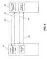
- FIG. 9illustrates a block diagram of the signal paths from the FTM to the IRD in accordance with the present invention.
- FTM 300is shown as having an interface 900 which is coupled to power injector 302 at interface 904 .
- power injector 302has an interface 906 coupled to splitter 306 at interface 908 .
- the other interfaces of splitter 306are coupled to other splitters 304 , which in turn are coupled to IRDs 308 .
- Each IRD 308 shown in FIG. 9can be a PVR 504 if desired.
- the cable 310contains the Radio Frequency (RF) signals that have been processed by the FTM 300 as described with respect to FIGS. 3 and 8 . These signals are then promulgated to the various IRDs 308 and PVRs 504 present in the system. Further, other interfaces 910 provide legacy IRDs 108 access to the LNB inputs 912 .
- RFRadio Frequency
- the same coaxial cable 310 that is used to promulgate the IRD requested signal 812also carries the IRD 308 generated requests for viewer channel information back to the FTM 300 .
- IRD 308 and power injector 302are both connected to house power lines at 110V, 60 Hz, power lines can be used to promulgate the commands between IRD 308 and power injector 302 .
- the splitters 304 and 306must be able to control the command path independent of the RF signal path, so that each IRD 308 continuously receives the IRD requested signal 812 or 416 , but has selective communication with FTM 300 .
- the selective communication pathis discussed with respect to the power injector 302 and splitters 304 and 306 below.
- FIG. 10is a block diagram of the power injector in accordance with the present invention.
- Power injector 302is coupled to FTM 300 by cable 302 and to IRD 308 by cable 1000 . Additional portions of the connection to IRD 308 are described in FIGS. 11 and 12 . Power injector 302 comprises a path that allows FTM 300 information to flow to IRDs 308 , e.g., satellite downlink signals 120 . Further, power injector 302 comprises a path for information to flow from IRDs 308 to FTM 300 , e.g., voltage and tone signals for selection of ports on the multiswitch. These paths, namely path 1002 from FTM 300 to IRD 308 , and path 1004 from IRD 308 to FTM 300 , are shown.
- the power injector 302typically uses a 24 V signal 1006 , which is also used to supply power to the circuits in the power injector 302 .
- Signal 1006may be at other voltages, e.g., 30 VDC, without departing from the scope of the present invention.
- Path 1004shows a voltage detection circuit at the IRD input 1000 , which needs to be capable of detecting signals with a frequency of 22 kHz up to 88 kHz, which are the signals used to select ports at the multiswitch.
- Path 1002shows a current detection circuit at the FTM output 310 , which needs to be capable of detecting signals with a frequency up to 88 KHz*4 and a detection circuit that can detect a delta current of 45 mA or higher.
- Paths 1002 and 1004are isolated, since if they are not isolated from each other, there is a substantial risk of oscillation. To obtain this isolation there is a blocking mechanism in both directions. If the DiSEqC signal travels from IRD 308 to FTM 300 , or vice versa, then one of the paths 1002 or 1004 is disabled by switches 1008 , 1010 , 1012 , and 1014 . As the present invention uses a half duplex system, there are no problems with disabling one direction while the other direction is active. The path 1002 or 1004 , whichever is first active, disables the other path.
- the power injector 302performs additional functions in the FTM 300 schema of the present invention.
- the power injector 302also translates voltages so that each control path 1002 and 1004 operates without collisions.
- the power injector 302can also send signals along the house's internal power lines to IRDs 308 .
- FIGS. 11 and 12illustrate signal splitters in accordance with the present invention.
- a block diagram of two-way splitter 304is shown, with the RF signal input 1100 and two RF signal outputs 1102 and 1104 .
- the RF signal input 1100is upstream of the RF signal outputs 1102 and 1104 for the satellite downlink signals 120 ; in other words, RF signal input is connected closer to the FTM 300 than the RF signal outputs 1102 and 1104 for a given two-way splitter 304 .
- RF signal input 1100may be coupled directly to FTM 300 , but RF signal input 1100 may also be connected to another two-way splitter 304 or four-way splitter 306 , in which case RF signal input 1100 would be coupled to an RF output 1104 .
- the RF signal outputs 1102 and 1104are also “reverse” inputs for commands that travel from the IRD 308 to the FTM 300 .
- the two-way splitter 304acts as a priority switch.
- both RF signal outputs 1102 and 1104have a DC voltage below 15 volts
- the highest voltage present on the RF signal outputs 1102 and 1104is transferred through switch 1106 to RF signal input 1100 .
- Thisallows power for other two-way splitters 304 or four-way splitters 306 that are coupled upstream (closer to the FTM 300 ) to be transferred for power needs of other splitters 304 or 306 .
- Microcontroller 1108polls RF signal outputs 1102 and 1104 for voltage and tone signals. This is typically done by looking for a voltage at junctions 1110 and 1112 , but can be performed in other ways without departing from the scope of the present invention.
- the microprocessor 1108detects a voltage above a certain threshold, then the microprocessor closes one of switches 1114 or 1116 .
- the thresholdis typically 16 volts, but can be a different voltage without departing from the scope of the present invention. For example, if microprocessor 1108 detects a voltage of 18 volts at junction 1110 , then microprocessor 1108 closes switch 1114 . Substantially at the same time, microprocessor 1108 opens switch 1106 to avoid the signal from charging capacitor 1118 .
- the microprocessor 1108If the microprocessor 1108 sees that the other RF signal output 1104 (as an example) also goes above a certain threshold, the microprocessor closes switch 1120 to inform the IRD 308 that is requesting FTM 300 attention that FTM 300 is busy. Once microprocessor 1108 sees that the voltage at junction 1110 has dropped below the threshold voltage, the microprocessor 1108 will open switch 1114 , close switch 1116 , and open switch 1120 to allow the IRD 308 coupled to RF signal output 1104 to communicate with FTM 300 .
- FIG. 12illustrates a four-way splitter 306 of the present invention, which operates similarly to the two-way splitter 304 described with respect to FIG. 11 , but has additional RF signal outputs 1200 and 1202 attached.
- the FTM 300allows for registration of the configuration of the house as installed by the installer, including the signal losses/AGC and time of transmission numbers, ODU 108 /IRD 308 /FTM 300 registration serial numbers, etc., which are all registered at the time of installation. If the phone line remains installed and connected to the IRD 308 and/or FTM 300 , the FTM 300 can verify the serial numbers, AGC and signal loss numbers, etc. and transmit these numbers to the service provider for use in troubleshooting and/or maintenance of the installed system. If there is a problem, or the installation configuration changes, the FTM 300 can detect this and attempt repairs and/or record new data for analysis. Such data may also be useful for fraud detection.
- IRD 308during initial setup, must determine if there is an FTM 300 installed in the system; otherwise, IRD 308 will not have a private channel and will be required to act as a legacy IRD 112 .
- a commandis sent that FTM 300 will understand (88 kHz, 1/0 format) that will not be understood by a non-FTM 300 system.
- IRD 308then waits for a specific amount of time, and either tries again (or x number of times) or performs a timeout routine. If a proper response is received, then IRD 308 knows there is an FTM 300 installed, and communication between IRD (with optional serial # encoding) and FTM (with optional serial # encoding) is established. Otherwise, no FTM 300 is present, and IRD 308 acts as a Legacy IRD 112 .
- associationsare created between ODU 108 , FTM 300 , and IRDs 308 such that each FTM 300 knows which IRDs 308 should be receiving signals.
- the data used to create these associationsare created during initial installation, or upgrades to the installation that are performed by customers or installation personnel.
- IRD 308is a valid IRD 308 for a given account after the initial registration process.
- the present inventionallows for additional checking to ensure that a given IRD 308 is receiving signals from the proper FTM 300 /ODU 108 pairing.
- a customercan purchase an IRD 308 and call the service provider for authorization to install the IRD 308 . Once installed, the IRD 308 must register through a specific FTM 300 . The association between that IRD 308 and that FTM 300 prevents the IRD 308 from being moved to a new FTM 300 at another location, because the authorization codes for the second FTM 300 do not authorize that FTM 300 to pass signals through to the moved IRD 308 .
- AGC changesmay alert the provider that a change in the in-home wiring has occurred.
- Some changesmay be authorized, e.g., a subscriber has been authorized to install another IRD 308 , or has moved an IRD 308 from one room to another.
- large deltas in AGCcan signal a possible fraudulent use situation. For example, and not by way of limitation, two neighbors can agree to use a single ODU 108 to feed one IRD 308 located in one house and another IRD 308 located in the neighbor's household.
- the cabling run to the house without the ODU 108will be much longer than the cable run into the first household, and thus, the AGC level required to drive the IRD 308 in the house without the ODU 108 will be much higher than the AGC level to drive the first IRD 308 .
- Such installationseven if authorized, can be a signal of possible fraudulent use. Time of travel over the cable wire, as well as signal loss (which AGC overcomes), and other methods can also be used during registration and/or modification of the system to determine possible fraudulent activity.
- the FTM 300 architecturenow only requires that one IRD 308 has access to a telephone line, rather then each IRD 308 .
- the phone line communications and authorizationscan be sent from one IRD 308 to the service provide because the FTM 300 can communicate with all IRDs 308 , and such data can be sent from the FTM 300 through any IRD 308 that has telephone connections.
- the FTM 300can stop delivery of signals to the IRDs 308 until there is a phone connection, which can be determined by the phone signaling voltages present on phone lines.
- the phone connectioncan be also checked on a periodic (random) basis, or can be verified via other methods, such as call in registration for services via IRD 308 , etc.
- the 13/18 VDC and 22/88 kHz protocol described hereinis only one protocol that can be used within the scope of the present invention.
- Other protocolse.g., ethernet, or other custom designed protocols, can be used without departing from the scope of the present invention.
- the 88 kHz signal(DiSeqC 1.0 uses 22 kHz) is just one example of a customized signal; other protocols, other bit patterns, other commands can be used instead.
- Phone linescan also be used for communication between IRDs/FTM or IRD-IRD directly.
- any IRD 308is interchangeable with PVR 504 in terms of commands and RF signal delivery.
- An apparatus in accordance with the present inventioncomprises a receive antenna, including at least one low noise block amplifier (LNB); and a module, coupled to and proximate the receive antenna, the module comprising a multiswitch, coupled to the LNB, for directing the satellite signal received by the LNB to an output of the multiswitch, at least one tuner, coupled to the output of the multiswitch, for tuning to a specific portion of the satellite signal, the specific portion of the satellite signal selected based on commands received from a new Integrated Receiver Decoder (IRD), at least one demodulator, coupled to the at least one tuner, for demodulating the specific portion of the signal into a plurality of demodulated signals, and an interface for delivering a specific demodulated signal to the new IRD, wherein the specific demodulated signal is selected based on the commands received from the new IRD, and the specific demodulated signal is mapped to a new address based on a private channel number associated with the new IRD
- the systemoptionally further comprises a way for the commands and the specific demodulated signal to be carried on a single connection between the at least one IRD and the interface, a plurality of new IRDs, wherein each IRD has a unique private channel number, and the interface delivers a combined signal comprising a plurality of specific demodulated signals, each demodulated signal selected based on commands received from each of the plurality of new IRDs, a controller, coupled to the interface, for controlling signal flow between the interface and the plurality of IRDs, and a second output of the multiswitch, wherein the second output is a legacy output that commands the multiswitch via a cable other than the single connection.
- the systemcan further include a network tuner, coupled between the multiswitch and the interface, wherein the network tuner is controlled by a service provider, allows for the controller to monitor signal strengths of the specific demodulated signals, and can also comprise an automatic gain controller, coupled between the multiswitch and the interface, for controlling the signal strengths of the specific demodulated signals.
- a network tunercoupled between the multiswitch and the interface, wherein the network tuner is controlled by a service provider, allows for the controller to monitor signal strengths of the specific demodulated signals
- an automatic gain controllercoupled between the multiswitch and the interface, for controlling the signal strengths of the specific demodulated signals.
- the modulecan also refuse commands from an IRD that requires a signals strength of the specific demodulated signal associated with that IRD that is larger than a predetermined amount.
- Another embodiment of the present inventioncomprises a multiswitch, for selectively directing the satellite video signals based on which satellite of the plurality of satellites broadcast the satellite video signal to an output of the multiswitch, at least one tuner, coupled to the output of the multiswitch, for tuning to a specific portion of the satellite video signal, the specific portion of the satellite signal selected based on a command received from the IRD, at least one demodulator, coupled to the at least one tuner in a respective fashion, for demodulating the specific portion of the signal into a plurality of demodulated signals, and an interface for delivering a specific demodulated signal to the IRD, wherein the specific demodulated signal is mapped to a new address based on a private channel number associated with the IRD.
- Optional items for this embodimentinclude an automatic gain controller, coupled between the multiswitch and the interface, for controlling the signal strengths of the specific demodulated signals, the specific demodulated signal being selected based on the command received from the IRD, a network tuner, coupled between the multiswitch and the interface, wherein the network tuner cannot be controlled by the IRD, a controller, coupled to the interface, for controlling signal flow between the interface and the plurality of IRDs, a second output of the multiswitch, wherein the second output is an output that commands the multiswitch via a connection other than the interface, the interface having an output comprising a combined signal, which comprises a plurality of individual signals, a first individual signal comprising an output of the network tuner, and additional individual signals comprising at least one specific demodulated signal, and the IRD receiving the entire combined signal and tunes to the individual signals based on the new address associated with the individual signal.
- an automatic gain controllercoupled between the multiswitch and the interface, for controlling the signal strengths of the specific demodulated
- Another embodiment of the present inventioncomprises a multiswitch, for selectively directing the satellite video signals based on which satellite of the plurality of satellites broadcast the satellite video signal to an output of the multiswitch, at least one tuner, coupled to the output of the multiswitch, for tuning to a specific portion of the satellite video signal, the specific portion of the satellite signal selected based on a command received from the IRD, and an interface for delivering the specific portion of the satellite signal to the IRD, wherein the portion is mapped to a new address based on a private channel number associated with the IRD.
- This embodimentcan also include the interface being a network interface, and an output of the interface being a combined signal, and the IRD selects a portion of the satellite signal based on the private channel number.
Landscapes
- Engineering & Computer Science (AREA)
- Signal Processing (AREA)
- Physics & Mathematics (AREA)
- Astronomy & Astrophysics (AREA)
- General Physics & Mathematics (AREA)
- Multimedia (AREA)
- Radar, Positioning & Navigation (AREA)
- Remote Sensing (AREA)
- Input Circuits Of Receivers And Coupling Of Receivers And Audio Equipment (AREA)
- Radio Relay Systems (AREA)
- Two-Way Televisions, Distribution Of Moving Picture Or The Like (AREA)
Abstract
Description
Claims (19)
Priority Applications (3)
| Application Number | Priority Date | Filing Date | Title |
|---|---|---|---|
| US11/097,479US7950038B2 (en) | 2005-04-01 | 2005-04-01 | Transponder tuning and mapping |
| EP06749163.9AEP1878246B1 (en) | 2005-04-01 | 2006-04-03 | Transponder tuning and mapping |
| PCT/US2006/012309WO2006107874A2 (en) | 2005-04-01 | 2006-04-03 | Transponder tuning and mapping |
Applications Claiming Priority (1)
| Application Number | Priority Date | Filing Date | Title |
|---|---|---|---|
| US11/097,479US7950038B2 (en) | 2005-04-01 | 2005-04-01 | Transponder tuning and mapping |
Publications (2)
| Publication Number | Publication Date |
|---|---|
| US20060225098A1 US20060225098A1 (en) | 2006-10-05 |
| US7950038B2true US7950038B2 (en) | 2011-05-24 |
Family
ID=37072165
Family Applications (1)
| Application Number | Title | Priority Date | Filing Date |
|---|---|---|---|
| US11/097,479Active2028-03-19US7950038B2 (en) | 2005-04-01 | 2005-04-01 | Transponder tuning and mapping |
Country Status (3)
| Country | Link |
|---|---|
| US (1) | US7950038B2 (en) |
| EP (1) | EP1878246B1 (en) |
| WO (1) | WO2006107874A2 (en) |
Cited By (1)
| Publication number | Priority date | Publication date | Assignee | Title |
|---|---|---|---|---|
| US20110151769A1 (en)* | 2008-09-26 | 2011-06-23 | John James Fitzpatrick | Method for controlling signal transmission for multiple devices |
Families Citing this family (21)
| Publication number | Priority date | Publication date | Assignee | Title |
|---|---|---|---|---|
| DE102005036810B4 (en)* | 2005-08-04 | 2007-09-06 | Kathrein-Werke Kg | HF socket |
| US8515342B2 (en)* | 2005-10-12 | 2013-08-20 | The Directv Group, Inc. | Dynamic current sharing in KA/KU LNB design |
| US7965977B2 (en)* | 2006-04-18 | 2011-06-21 | 2Wire, Inc. | Remote antenna system |
| US8520835B2 (en)* | 2006-04-18 | 2013-08-27 | 2Wire, Inc. | Method and apparatus for providing power to a network interface device via telephone lines |
| WO2007149414A2 (en)* | 2006-06-19 | 2007-12-27 | The Directv Group, Inc. | Dedicated tuner for network administration functions |
| US20080101415A1 (en)* | 2006-10-25 | 2008-05-01 | Microsoft Corporation | Private data transmission via an analog broadcast transmission |
| CN101689942B (en)* | 2007-03-26 | 2013-04-24 | 汤姆森特许公司 | Six port linear network single wire multi switch transceiver |
| US9247274B2 (en) | 2013-01-16 | 2016-01-26 | Maxlinear, Inc. | Flexible channel stacking |
| US8572661B2 (en) | 2009-06-17 | 2013-10-29 | Echostar Technologies L.L.C. | Satellite signal distribution |
| US9319644B2 (en)* | 2009-07-20 | 2016-04-19 | Bce Inc. | Automatic user band assignment in a satellite signal distribution environment |
| US8953802B2 (en)* | 2009-07-20 | 2015-02-10 | Bce Inc. | Signal security in a satellite signal distribution environment |
| US20110058518A1 (en)* | 2009-09-09 | 2011-03-10 | Comtech Ef Data Corp. | Multi-Channel Single Carrier Per Channel (SCPC) Systems and Related Methods |
| WO2011075811A1 (en) | 2009-12-21 | 2011-06-30 | Bce Inc. | Methods and systems for re-securing a compromised channel in a satellite signal distribution environment |
| US20110149171A1 (en)* | 2009-12-21 | 2011-06-23 | Cowley Nicholas P | Efficient tuning and demodulation techniques |
| US8639179B2 (en) | 2011-04-16 | 2014-01-28 | Entropic Communications, Inc. | Single-cable automatic IRD installation procedure |
| US8799964B2 (en)* | 2012-02-08 | 2014-08-05 | Maxlinear, Inc. | Method and system for integrated stacking for handling channel stacking or band stacking |
| US9160468B1 (en)* | 2012-06-15 | 2015-10-13 | Maxlinear, Inc. | Method and system for reconfigurable time-interleaved ADC for direct conversion K-band and L-band I/Q |
| US9924233B2 (en)* | 2015-04-22 | 2018-03-20 | The Directv Group, Inc. | Systems and methods for controlling a single-wire multiswitch device |
| DE102015011875A1 (en)* | 2015-09-10 | 2017-03-16 | Kathrein-Werke Kg | Device for transmitting and receiving mobile radio signals by means of a stationary antenna |
| US10070181B2 (en)* | 2016-07-20 | 2018-09-04 | Microelectronics Technology, Inc. | Power splitter and satellite signal reception system |
| CN106603089B (en)* | 2017-01-16 | 2018-10-16 | 北京星网卫通科技开发有限公司 | A kind of more local oscillator control method and device of more LNB |
Citations (213)
| Publication number | Priority date | Publication date | Assignee | Title |
|---|---|---|---|---|
| US3581209A (en) | 1968-09-17 | 1971-05-25 | Arie Zimmerman | Cable television program capacity enhancement |
| US3670275A (en) | 1970-03-20 | 1972-06-13 | Vaisala Oy | Electronic and automatic selector device connected to an antenna array formed by two or more antennas |
| US4064460A (en) | 1974-03-16 | 1977-12-20 | Communications Patents Limited | Coaxial wired broadcasting system with tone responsive program selectors |
| US4132952A (en) | 1975-11-11 | 1979-01-02 | Sony Corporation | Multi-band tuner with fixed broadband input filters |
| US4354167A (en) | 1980-12-08 | 1982-10-12 | 501 Centre De Recherche Industrielle Du Quebec | Multi-subscriber differentiation and distribution switching system having interchangeable differentiating circuits |
| US4382266A (en) | 1979-12-20 | 1983-05-03 | Siemens Aktiengesellschaft | Broad band switching system |
| US4397037A (en) | 1981-08-19 | 1983-08-02 | Rca Corporation | Diplexer for television tuning systems |
| US4403343A (en) | 1980-09-30 | 1983-09-06 | Clarion Co., Ltd. | Diversity receiver |
| GB2127257A (en) | 1982-08-17 | 1984-04-04 | Visionhire Cable Limited | Distribution apparatus |
| US4509198A (en) | 1981-10-19 | 1985-04-02 | Dx Antenna Company, Limited | Satellite broadcast signal receiving system |
| US4513315A (en) | 1981-06-25 | 1985-04-23 | U.S. Philips Corporation | Community antenna television arrangement for the reception and distribution of TV - and digital audio signals |
| US4530008A (en) | 1983-10-03 | 1985-07-16 | Broadband Technologies, Inc. | Secured communications system |
| US4532543A (en) | 1981-12-14 | 1985-07-30 | U.S. Philips Corporation | High channel density community antenna arrangement having low intermodulation products |
| US4538175A (en) | 1980-07-11 | 1985-08-27 | Microdyne Corporation | Receive only earth satellite ground station |
| US4545075A (en) | 1981-11-18 | 1985-10-01 | Times Fiber Communications, Inc. | Satellite block transmission using wideband fiber optic links |
| US4556988A (en) | 1982-09-27 | 1985-12-03 | Alps. Electric Co., Ltd. | Indoor unit of receiver for broadcasting satellite |
| US4592093A (en) | 1984-01-13 | 1986-05-27 | Sony Corporation | Super high frequency receiver |
| US4608710A (en) | 1982-07-15 | 1986-08-26 | Masprodenkoh Kabushikikaisha | Apparatus for receiving satellite broadcasts |
| US4628506A (en) | 1983-10-21 | 1986-12-09 | Ant Nachrichtentechnik Gmbh | Method for transmitting communications services via satellites |
| US4656486A (en) | 1985-07-12 | 1987-04-07 | Turner Allan L | Satellite TV dish antenna support |
| US4663513A (en) | 1985-11-26 | 1987-05-05 | Spectra-Physics, Inc. | Method and apparatus for monitoring laser processes |
| US4667243A (en) | 1985-10-31 | 1987-05-19 | Rca Corporation | Television receiver for direct broadcast satellite signals |
| US4672687A (en) | 1985-01-29 | 1987-06-09 | Satellite Technology Services, Inc. | Polarity switch for satellite television receiver |
| US4675732A (en) | 1984-12-19 | 1987-06-23 | Nordspace Aktiebolag | Satellite/hybrid television system |
| US4710972A (en) | 1985-10-21 | 1987-12-01 | Sony Corporation | SHF receiver |
| US4723320A (en) | 1985-03-28 | 1988-02-02 | Satellite Technology Services, Inc. | Dual communication link for satellite TV receiver |
| US4761825A (en) | 1985-10-30 | 1988-08-02 | Capetronic (Bsr) Ltd. | TVRO earth station receiver for reducing interference and improving picture quality |
| US4761827A (en) | 1984-09-17 | 1988-08-02 | Satellite Technology Services, Inc. | Polarity switch for satellite television receiver |
| US4785306A (en) | 1986-01-17 | 1988-11-15 | General Instrument Corporation | Dual frequency feed satellite antenna horn |
| US4802239A (en) | 1985-07-18 | 1989-01-31 | Kabushiki Kaisha Toshiba | Switch distributing apparatus for community reception |
| US4805014A (en) | 1983-11-07 | 1989-02-14 | Sony Corporation | Signal transmission system for a CATV system |
| US4813036A (en) | 1985-11-27 | 1989-03-14 | National Exchange, Inc. | Fully interconnected spot beam satellite communication system |
| US4823135A (en) | 1985-10-01 | 1989-04-18 | Matsushita Electric Industrial Co., Ltd. | Satellite receiver having improved polarization plane determination means |
| US4860021A (en) | 1985-06-28 | 1989-08-22 | Hitachi, Ltd. | Parabolic antenna |
| US4876736A (en) | 1987-09-23 | 1989-10-24 | A. C. Nielsen Company | Method and apparatus for determining channel reception of a receiver |
| US4885803A (en) | 1987-03-17 | 1989-12-05 | Lawrence W. Hermann | System and method for controlling a plurality of electronic entertainment devices |
| US4903031A (en) | 1985-03-26 | 1990-02-20 | Trio Kabushiki Kaisha | Satellite receiver |
| US4945410A (en) | 1987-02-09 | 1990-07-31 | Professional Satellite Imaging, Inc. | Satellite communications system for medical related images |
| US5010400A (en) | 1988-08-03 | 1991-04-23 | Kabushiki Kaisha Toshiba | Television tuner for receiving multiple band television signals |
| US5027430A (en) | 1987-07-24 | 1991-06-25 | Sharp Kabushiki Kaisha | Outdoor unit low noise converter for satellite broadcast reception use |
| US5068918A (en) | 1989-06-08 | 1991-11-26 | U.S. Philips Corporation | Receiver for terrestrial am and satellite fm-tv broadcasting signals |
| US5073930A (en) | 1989-10-19 | 1991-12-17 | Green James A | Method and system for receiving and distributing satellite transmitted television signals |
| US5119509A (en) | 1988-08-09 | 1992-06-02 | Samsung Electronics Co., Ltd. | Low noise block down converter (LNB) for the simultaneous receipt of C/Ku-band satellite-broadcasting |
| US5235619A (en) | 1990-03-20 | 1993-08-10 | Scientific-Atlanta, Inc. | Cable television radio frequency subscriber data transmission apparatus and rf return method |
| US5249043A (en) | 1990-07-30 | 1993-09-28 | Compagnie Generale De Videotechnique (C.G.V.) | Device for dispatching video and/or audio signals between several receivers |
| US5276904A (en) | 1989-07-04 | 1994-01-04 | Thomson Composants Microondes | System for receiving TV signals retransmitted by satellites |
| US5289272A (en) | 1992-02-18 | 1994-02-22 | Hughes Aircraft Company | Combined data, audio and video distribution system in passenger aircraft |
| EP0288928B1 (en) | 1987-04-27 | 1994-03-09 | EDICO S.r.l. | Disposition for satellite direct reception of television programmes |
| US5301352A (en) | 1991-07-04 | 1994-04-05 | Sony Corporation | Satellite broadcast receiving system and change-over divider for use in same |
| US5382971A (en) | 1992-08-19 | 1995-01-17 | U.S. Philips Corporation | Television signal cable distribution system and assembly of elements for constituting such a system |
| US5437051A (en) | 1991-09-19 | 1995-07-25 | Kabushiki Kaisha Toshiba | Broadband tuning circuit for receiving multi-channel signals over a broad frequency range |
| US5521631A (en) | 1994-05-25 | 1996-05-28 | Spectravision, Inc. | Interactive digital video services system with store and forward capabilities |
| US5572517A (en) | 1995-02-28 | 1996-11-05 | General Instrument Corporation | Configurable hybrid medium access control for cable metropolitan area networks |
| US5574964A (en) | 1995-05-30 | 1996-11-12 | Apple Computer, Inc. | Signal distribution system |
| US5587734A (en) | 1990-09-28 | 1996-12-24 | Ictv, Inc. | User interface for selecting television information services through pseudo-channel access |
| US5617107A (en) | 1995-09-01 | 1997-04-01 | Perfect Ten Antenna Co. Inc. | Heated microwave antenna |
| US5649318A (en) | 1995-03-24 | 1997-07-15 | Terrastar, Inc. | Apparatus for converting an analog c-band broadcast receiver into a system for simultaneously receiving analog and digital c-band broadcast television signals |
| US5675390A (en) | 1995-07-17 | 1997-10-07 | Gateway 2000, Inc. | Home entertainment system combining complex processor capability with a high quality display |
| US5708961A (en) | 1995-05-01 | 1998-01-13 | Bell Atlantic Network Services, Inc. | Wireless on-premises video distribution using digital multiplexing |
| US5734356A (en) | 1996-06-07 | 1998-03-31 | Rf-Link Systems, Inc. | Construction for portable disk antenna |
| US5748732A (en) | 1995-02-08 | 1998-05-05 | U.S. Philips Corporation | Pay TV method and device which comprise master and slave decoders |
| US5760822A (en) | 1996-01-30 | 1998-06-02 | Lucent Technologies Inc. | Central node converter for local network having single coaxial cable |
| US5760819A (en) | 1996-06-19 | 1998-06-02 | Hughes Electronics | Distribution of a large number of live television programs to individual passengers in an aircraft |
| US5787335A (en) | 1996-11-18 | 1998-07-28 | Ethnic-American Broadcasting Co, Lp | Direct broadcast satellite system for multiple dwelling units |
| US5790202A (en) | 1996-05-15 | 1998-08-04 | Echostar Communications Corporation | Integration of off-air and satellite TV tuners in a direct broadcast system |
| US5793413A (en) | 1995-05-01 | 1998-08-11 | Bell Atlantic Network Services, Inc. | Wireless video distribution |
| US5805806A (en) | 1995-12-18 | 1998-09-08 | Intel Corporation | Method and apparatus for providing interactive networking between televisions and personal computers |
| US5805975A (en) | 1995-02-22 | 1998-09-08 | Green, Sr.; James A. | Satellite broadcast receiving and distribution system |
| US5835128A (en) | 1996-11-27 | 1998-11-10 | Hughes Electronics Corporation | Wireless redistribution of television signals in a multiple dwelling unit |
| US5838740A (en) | 1996-04-17 | 1998-11-17 | Motorola, Inc. | Crosspole interference canceling receiver for signals with unrelated baud rates |
| US5848239A (en) | 1996-09-30 | 1998-12-08 | Victory Company Of Japan, Ltd. | Variable-speed communication and reproduction system |
| US5864747A (en) | 1995-08-24 | 1999-01-26 | General Dynamics Information Systems, Inc. | Data bridge |
| US5883677A (en) | 1995-03-13 | 1999-03-16 | Panasonic Technologies Inc. | Method and apparatus for managing multiple outside video service providers |
| US5886995A (en) | 1996-09-05 | 1999-03-23 | Hughes Electronics Corporation | Dynamic mapping of broadcast resources |
| US5898455A (en) | 1997-12-23 | 1999-04-27 | California Amplifier, Inc. | Interface modules and methods for coupling combined communication signals to communication receivers |
| US5905942A (en) | 1997-02-18 | 1999-05-18 | Lodgenet Entertainment Corporation | Multiple dwelling unit interactive audio/video distribution system |
| US5905941A (en) | 1995-12-20 | 1999-05-18 | U.S. Philips Corporation | Television signal cable distribution installation |
| US5923288A (en) | 1997-03-25 | 1999-07-13 | Sony Coporation | Antenna alignment indicator system for satellite receiver |
| US5936660A (en) | 1996-12-12 | 1999-08-10 | Rockwell Semiconductor System, Inc. | Digital video converter box for subscriber/home with multiple television sets |
| US5959592A (en) | 1996-03-18 | 1999-09-28 | Echostar Engineering Corporation | "IF" bandstacked low noise block converter combined with diplexer |
| US5970386A (en) | 1997-01-27 | 1999-10-19 | Hughes Electronics Corporation | Transmodulated broadcast delivery system for use in multiple dwelling units |
| US5982333A (en) | 1997-09-03 | 1999-11-09 | Qualcomm Incorporated | Steerable antenna system |
| US6005861A (en) | 1995-11-22 | 1999-12-21 | Samsung Electronics Co., Ltd. | Home multimedia network architecture |
| US6011597A (en) | 1996-06-08 | 2000-01-04 | Fujitsu Limited | Signal receiving apparatus and signal receiving system |
| US6023603A (en) | 1996-11-01 | 2000-02-08 | Masprodenkoh Kabushikikaisha | Satellite signal splitter |
| US6038425A (en) | 1998-08-03 | 2000-03-14 | Jeffrey; Ross A. | Audio/video signal redistribution system |
| US6100883A (en) | 1990-09-28 | 2000-08-08 | Ictv, Inc. | Home interface controller for providing interactive cable television |
| US6104908A (en) | 1997-02-28 | 2000-08-15 | Hughes Electronics Corporation | System for and method of combining signals of combining signals of diverse modulation formats for distribution in multiple dwelling units |
| US6147714A (en) | 1995-07-21 | 2000-11-14 | Sony Corporation | Control apparatus and control method for displaying electronic program guide |
| US6173164B1 (en) | 1997-09-15 | 2001-01-09 | Wireless Access | Method and apparatus for wide range automatic frequency control |
| US6188372B1 (en) | 1999-06-17 | 2001-02-13 | Channel Master Llc | Antenna with molded integral polarity plate |
| US6192399B1 (en) | 1997-07-11 | 2001-02-20 | Inline Connections Corporation | Twisted pair communication system |
| US6198479B1 (en) | 1997-06-25 | 2001-03-06 | Samsung Electronics Co., Ltd | Home network, browser based, command and control |
| US6198449B1 (en) | 1994-09-01 | 2001-03-06 | E*Star, Inc. | Multiple beam antenna system for simultaneously receiving multiple satellite signals |
| US6202211B1 (en) | 1998-02-06 | 2001-03-13 | Henry R. Williams, Jr. | Method and apparatus for providing television signals to multiple viewing systems on a network |
| JP2001231033A (en) | 2000-02-17 | 2001-08-24 | Dx Antenna Co Ltd | Joint receiving system and frequency conversion device for terminal thereof |
| JP2001237752A (en) | 1999-12-30 | 2001-08-31 | Itis | Transmission system having space diversity, time diversity, and frequency diversity |
| US6292567B1 (en) | 1997-08-26 | 2001-09-18 | Eagle Comtronics, Inc. | Sync suppression television security system with addressable sync restoration |
| US6304618B1 (en) | 1998-08-31 | 2001-10-16 | Ericsson Inc. | Methods and systems for reducing co-channel interference using multiple timings for a received signal |
| US20010055319A1 (en) | 1998-10-30 | 2001-12-27 | Broadcom Corporation | Robust techniques for optimal upstream communication between cable modem subscribers and a headend |
| US6340956B1 (en) | 1999-11-12 | 2002-01-22 | Leland H. Bowen | Collapsible impulse radiating antenna |
| US20020044614A1 (en) | 2000-09-12 | 2002-04-18 | Molnar Karl James | Methods and systems for reducing interference using co-channel interference mapping |
| US6397038B1 (en) | 1995-02-22 | 2002-05-28 | Global Communications, Inc. | Satellite broadcast receiving and distribution system |
| DE19749120C2 (en) | 1997-11-06 | 2002-07-18 | Kathrein Werke Kg | Satellite reception system and associated method for operating an antenna reception system |
| US6424817B1 (en) | 1998-02-04 | 2002-07-23 | California Amplifier, Inc. | Dual-polarity low-noise block downconverter systems and methods |
| US6430742B1 (en) | 1997-08-27 | 2002-08-06 | Koninklijke Philips Electronics N.V. | Device for distributing television signals by cable |
| US6430233B1 (en) | 1999-08-30 | 2002-08-06 | Hughes Electronics Corporation | Single-LNB satellite data receiver |
| US6441797B1 (en) | 2000-09-29 | 2002-08-27 | Hughes Electronics Corporation | Aggregated distribution of multiple satellite transponder signals from a satellite dish antenna |
| US6442148B1 (en) | 1998-12-23 | 2002-08-27 | Hughes Electronics Corporation | Reconfigurable multibeam communications satellite having frequency channelization |
| US6452991B1 (en) | 1998-12-30 | 2002-09-17 | Ericsson Inc. | Systems and methods for acquiring channel synchronization in time division multiple access communications systems using dual detection thresholds |
| US20020140617A1 (en) | 2001-03-12 | 2002-10-03 | Luly Robert A. | Multi-band antenna for bundled broadband satellite internet access and DBS television service |
| US6463266B1 (en) | 1999-08-10 | 2002-10-08 | Broadcom Corporation | Radio frequency control for communications systems |
| US20020152467A1 (en) | 2001-02-12 | 2002-10-17 | Rosario Fiallos | Automated generation of conditional access packets for IRD upgrades via radio frequency software download in satellite television systems |
| US20020154620A1 (en) | 2001-02-23 | 2002-10-24 | Yehuda Azenkot | Head end receiver for digital data delivery systems using mixed mode SCDMA and TDMA multiplexing |
| US20020154055A1 (en) | 2001-04-18 | 2002-10-24 | Robert Davis | LAN based satellite antenna/satellite multiswitch |
| US6486907B1 (en) | 1997-01-07 | 2002-11-26 | Foxcom Ltd. | Satellite distributed television |
| US20020178454A1 (en) | 2001-02-14 | 2002-11-28 | Antoine Mark J. | Broadcast television and satellite signal switching system and method for telephony signal insertion |
| US20020181604A1 (en) | 2001-04-27 | 2002-12-05 | Chen Ernest C. | Layered modulation for digital signals |
| US6493874B2 (en) | 1995-11-22 | 2002-12-10 | Samsung Electronics Co., Ltd. | Set-top electronics and network interface unit arrangement |
| US6510152B1 (en) | 1997-12-31 | 2003-01-21 | At&T Corp. | Coaxial cable/twisted pair fed, integrated residence gateway controlled, set-top box |
| US20030023978A1 (en) | 2001-07-25 | 2003-01-30 | Bajgrowicz Brian David | Satellite television system |
| US6549582B1 (en) | 1998-02-04 | 2003-04-15 | Virtual Satellite, Inc. | Method and apparatus for combining transponders on multiple satellites into virtual channels |
| CN1413021A (en) | 2002-08-27 | 2003-04-23 | 强海胜 | Multi-edition TV program satellite broadcast/automatic receiving, editing and recording transmission method |
| DE10155481A1 (en) | 2001-11-13 | 2003-05-28 | Fachhochschule Dortmund | Device for controlling/monitoring release of reception signals at domestic cable distribution system connection points has central control unit directly connected to connection points |
| US6574235B1 (en) | 1999-08-12 | 2003-06-03 | Ericsson Inc. | Methods of receiving co-channel signals by channel separation and successive cancellation and related receivers |
| US20030129960A1 (en) | 2002-01-07 | 2003-07-10 | Masahiro Kato | Satellite broadcast receiving converter with lower power consumption |
| US6598231B1 (en) | 1998-09-08 | 2003-07-22 | Asvan Technology, Llc | Enhanced security communications system |
| US6600730B1 (en) | 1998-08-20 | 2003-07-29 | Hughes Electronics Corporation | System for distribution of satellite signals from separate multiple satellites on a single cable line |
| US6600897B1 (en) | 1999-01-27 | 2003-07-29 | Alps Electric Co., Ltd. | Satellite-broadcasting receiving converter with a plurality of output terminals |
| GB2354650B (en) | 1999-06-25 | 2003-07-30 | Nec Corp | Automatic frequency control circuit |
| US6622307B1 (en)* | 1999-03-26 | 2003-09-16 | Hughes Electronics Corporation | Multiple-room signal distribution system |
| US20030185174A1 (en) | 1999-08-31 | 2003-10-02 | Currivan Bruce J. | Cancellation of interference in a communication system with application to S-CDMA |
| US20030217362A1 (en) | 2001-12-28 | 2003-11-20 | Summers Macy W. | Wideband direct-to-home broadcasting satellite communications system and method |
| US6653981B2 (en) | 2001-11-01 | 2003-11-25 | Tia Mobile, Inc. | Easy set-up, low profile, vehicle mounted, satellite antenna |
| US20030220072A1 (en) | 2002-05-22 | 2003-11-27 | Coffin Louis F | Satellite receiving system with transmodulating outdoor unit |
| JP2003339030A (en) | 2003-05-12 | 2003-11-28 | Matsushita Electric Ind Co Ltd | Program information creation transmission apparatus and method |
| US20040060065A1 (en)* | 2002-09-25 | 2004-03-25 | James Thomas H. | Direct broadcast signal distribution methods |
| US20040064689A1 (en) | 2002-09-27 | 2004-04-01 | Carr Jeffrey Douglas | System and method for securely handling control information |
| US20040068747A1 (en) | 2002-10-02 | 2004-04-08 | Robertson Neil C. | Networked multimedia system |
| US6728513B1 (en) | 1999-10-29 | 2004-04-27 | Sharp Kabushiki Kaisha | Receiving apparatus shared by multiple tuners |
| US6762727B2 (en) | 2001-10-09 | 2004-07-13 | Tyco Electronics Corporation | Quick-attach, single-sided automotive antenna attachment assembly |
| US20040136455A1 (en) | 2002-10-29 | 2004-07-15 | Akhter Mohammad Shahanshah | Efficient bit stream synchronization |
| US20040153942A1 (en) | 2003-01-24 | 2004-08-05 | Nathan Shtutman | Soft input soft output decoder for turbo codes |
| WO2004054128A3 (en) | 2002-12-11 | 2004-08-05 | R F Magic Inc | Integrated crosspoint switch with band translation |
| EP1447987A1 (en) | 2003-02-13 | 2004-08-18 | Broadcom Corporation | Communications signal transcoder |
| US20040184521A1 (en) | 2001-04-27 | 2004-09-23 | Chen Ernest C. | Equalizers for layered modulated and other signals |
| US20040192190A1 (en) | 2003-03-25 | 2004-09-30 | Sharp Kabushiki Kaisha | Low noise block down converter with reduced power consumption |
| US20040198237A1 (en) | 2001-06-19 | 2004-10-07 | Abutaleb Mohammed Gomma | Diplexer/switch circuit with modem capabilities |
| US20040203425A1 (en)* | 2002-06-27 | 2004-10-14 | Coffin Louis F. | Method and apparatus for adjusting signal component strength |
| US20040229583A1 (en) | 2003-02-19 | 2004-11-18 | Hitoshi Ogino | Digital broadcast receiving tuner and receiving device incorporating it |
| US20040244059A1 (en) | 2003-05-30 | 2004-12-02 | Lsi Logic Corporation | Digital set-top box transmodulator |
| US20040244044A1 (en) | 2001-04-18 | 2004-12-02 | Brommer Karl D | Bandwidth efficient cable network modem |
| US20040255229A1 (en) | 2003-06-13 | 2004-12-16 | Ba-Zhong Shen | Iterative metric updating when decoding LDPC (Low Density Parity Check) coded signals and LDPC coded modulation signals |
| US20040261110A1 (en)* | 2003-06-23 | 2004-12-23 | Lodgenet Entertainment Corporation | Lodging entertainment system with guest controlled integrated receiver decoder |
| GB2377111B (en) | 2001-04-03 | 2005-01-05 | Pace Micro Tech Plc | Secure operation of multiple set top boxes for broadcast data receivers |
| US20050002640A1 (en) | 2003-07-02 | 2005-01-06 | Daniel Putterman | Networked personal video recording system |
| US20050033846A1 (en) | 2000-05-02 | 2005-02-10 | Microsoft Corporation | Resource manager architecture |
| US6864855B1 (en) | 2003-09-11 | 2005-03-08 | Dx Antenna Company, Limited | Dish antenna rotation apparatus |
| US6865193B2 (en) | 1999-02-22 | 2005-03-08 | Neil D. Terk | Video transmission system and method utilizing phone lines in multiple unit dwellings |
| US20050052335A1 (en) | 2003-09-10 | 2005-03-10 | Shih-Hong Chen | Antenna and antenna adjustment structure |
| US20050054315A1 (en) | 2001-12-21 | 2005-03-10 | Bajgrowicz Brian David | Multiple rf signal switching apparatus |
| US20050060525A1 (en) | 2003-09-12 | 2005-03-17 | Schwartz James A. | Language for performing high level actions using hardware registers |
| US20050066367A1 (en) | 2003-09-19 | 2005-03-24 | Fyke Gregory James | Integrated receiver decoder for receiving digitally modulated signals from a satellite |
| US20050071882A1 (en) | 1999-06-11 | 2005-03-31 | Rodriguez Arturo A. | Systems and method for adaptive scheduling and dynamic bandwidth resource allocation management in a digital broadband delivery system |
| US6879301B2 (en) | 2001-10-09 | 2005-04-12 | Tyco Electronics Corporation | Apparatus and articles of manufacture for an automotive antenna mounting gasket |
| US6889385B1 (en) | 2000-01-14 | 2005-05-03 | Terayon Communication Systems, Inc | Home network for receiving video-on-demand and other requested programs and services |
| US20050118984A1 (en) | 2003-11-27 | 2005-06-02 | Hitoshi Akiyama | Receiving, displaying, and recording apparatus |
| US6906673B1 (en) | 2000-12-29 | 2005-06-14 | Bellsouth Intellectual Property Corporation | Methods for aligning an antenna with a satellite |
| US20050138663A1 (en) | 2003-12-19 | 2005-06-23 | Throckmorton John A. | Distributed video recording and playback |
| US20050184923A1 (en) | 2004-02-23 | 2005-08-25 | Mitsumi Electric Co. Ltd. | Fixing device for fixing an object to a fixing plate and antenna apparatus using the fixing device |
| US20050190777A1 (en) | 2003-06-30 | 2005-09-01 | Hess Kendal M. | Simultaneous multiple channel receiver |
| US20050193419A1 (en)* | 2003-06-30 | 2005-09-01 | Mats Lindstrom | Satellite multi-choice switch system |
| US6941576B2 (en) | 1999-04-12 | 2005-09-06 | Texas Instruments Incorporated | System and methods for home network communications |
| US20050198673A1 (en) | 2003-11-03 | 2005-09-08 | John Kit | Satellite TV security system |
| US6944878B1 (en) | 1999-07-19 | 2005-09-13 | Thomson Licensing S.A. | Method and apparatus for selecting a satellite signal |
| US20050204388A1 (en) | 1998-06-11 | 2005-09-15 | Knudson Edward B. | Series reminders and series recording from an interactive television program guide |
| US20050229206A1 (en) | 2002-05-10 | 2005-10-13 | Pugel Michael A | Television signal receiver capable of receiving emergency alert signals |
| US20050240969A1 (en) | 2003-02-06 | 2005-10-27 | Matsushita Electric Industrial Co., Ltd. | Antenna switching device and method thereof |
| US20050264395A1 (en) | 2004-02-23 | 2005-12-01 | Thierry Bassi | Method of communication between domestic appliances and appliances implementing the method |
| US20050289605A1 (en) | 2004-06-28 | 2005-12-29 | Samsung Electro-Mechanics Co., Ltd. | Intelligent low-noise block down-converter |
| US20060018345A1 (en) | 2004-07-26 | 2006-01-26 | Sbc Knowledge Ventures, Lp | System and method for distributing DBS content to multiple receivers in the home over a single coax |
| US20060030259A1 (en) | 2002-12-12 | 2006-02-09 | Herbert Hetzel | Dissemination system for satellite broadcasting |
| US20060041912A1 (en) | 2004-08-19 | 2006-02-23 | Kevin Kuhns | Method and apparatus for authorizing an additional set-top device in a satellite television network |
| WO2006015186A3 (en) | 2004-07-30 | 2006-03-09 | Matsushita Electric Industrial Co Ltd | System and method for distributed sharing and recording of live-tv |
| US7016643B1 (en) | 2003-01-10 | 2006-03-21 | The Directv Group, Inc. | Antenna positioning system and method for simultaneous reception of signals from a plurality of satellites |
| US7020081B1 (en) | 1998-07-10 | 2006-03-28 | Matsushita Electric Industrial Co., Ltd. | Stream distribution system |
| FR2861939B1 (en) | 2003-10-31 | 2006-03-31 | Neotion | SATELLITE RECEIVER BINDING UNIT. |
| US20060080707A1 (en) | 2001-05-24 | 2006-04-13 | Indra Laksono | Channel selection in a multimedia system |
| US7039169B2 (en) | 2002-09-25 | 2006-05-02 | Lsi Logic Corporation | Detection and authentication of multiple integrated receiver decoders (IRDs) within a subscriber dwelling |
| WO2005094075A3 (en) | 2004-04-30 | 2006-05-26 | Ucentric Holdings Inc | Centralized resource management and un-managed device support |
| US20060133612A1 (en) | 2004-12-21 | 2006-06-22 | Abedi Scott S | System and method of preventing alteration of data on a wireless device |
| US7069574B1 (en) | 1999-09-02 | 2006-06-27 | Broadlogic Network Technologies, Inc. | System time clock capture for computer satellite receiver |
| US7085529B1 (en) | 2001-10-24 | 2006-08-01 | The Directv Group, Inc. | Method and apparatus for determining a direct-to-home satellite receiver multi-switch type |
| US20060174282A1 (en) | 2005-01-31 | 2006-08-03 | Pro Brand International, Inc. | Bi-directional signal coupler |
| WO2006017218A3 (en) | 2004-07-13 | 2006-09-14 | Matsushita Electric Industrial Co Ltd | Tuner service and dtv receiver as a upnp device |
| US20060225104A1 (en) | 2005-04-01 | 2006-10-05 | James Thomas H | Power balancing signal combiner |
| US7130576B1 (en)* | 2001-11-07 | 2006-10-31 | Entropic Communications, Inc. | Signal selector and combiner for broadband content distribution |
| US20060259929A1 (en) | 2005-04-01 | 2006-11-16 | James Thomas H | Automatic level control for incoming signals of different signal strengths |
| US20060294512A1 (en) | 2005-06-22 | 2006-12-28 | Comcast Cable Holdings, Llc | System and method for generating a set top box code download step sequence |
| EP1207688B1 (en) | 2000-11-15 | 2007-01-24 | Pace Micro Technology PLC | Broadcast data receiver |
| US20070083898A1 (en) | 2005-10-12 | 2007-04-12 | John Norin | Band upconverter approach to Ka/Ku signal distribution |
| US7239285B2 (en) | 2004-05-18 | 2007-07-03 | Probrand International, Inc. | Circular polarity elliptical horn antenna |
| US7245671B1 (en) | 2001-04-27 | 2007-07-17 | The Directv Group, Inc. | Preprocessing signal layers in a layered modulation digital signal system to use legacy receivers |
| US7257638B2 (en) | 2001-12-20 | 2007-08-14 | Microsoft Corporation | Distributing network applications |
| US7260069B2 (en) | 2000-06-15 | 2007-08-21 | Gilat Satellite Networks, Inc. | System and method for satellite based controlled ALOHA |
| US20070202800A1 (en) | 1998-04-03 | 2007-08-30 | Roswell Roberts | Ethernet digital storage (eds) card and satellite transmission system |
| US20080064355A1 (en) | 2006-09-13 | 2008-03-13 | Ilan Sutskover | Method and apparatus for efficiently applying frequency correction |
| EP1331810B1 (en) | 2000-09-26 | 2008-11-12 | Matsushita Electric Industrial Co., Ltd. | Controlling a receiver |
| US7519680B1 (en) | 2001-07-16 | 2009-04-14 | At&T Corp. | Method for using scheduled hyperlinks to record multimedia content |
| US7522875B1 (en) | 2004-12-31 | 2009-04-21 | Entropic Communications Inc. | Signal selector and combiner system for broadband content distribution |
| US20090150937A1 (en) | 1998-07-14 | 2009-06-11 | United Video Properties, Inc. | Client-server based interactive television program guide system with remote server recording |
| US20090222875A1 (en) | 2002-04-18 | 2009-09-03 | Cheng David J | Distributed tuner allocation and conflict resolution |
| US20090252316A1 (en) | 2008-04-07 | 2009-10-08 | Kiril Ratmanski | Distributed Bridging |
Family Cites Families (2)
| Publication number | Priority date | Publication date | Assignee | Title |
|---|---|---|---|---|
| US6879696B1 (en)* | 2000-06-06 | 2005-04-12 | Phonak Ag | In-ear hearing aid and method for its manufacture |
| US7389113B2 (en)* | 2003-12-02 | 2008-06-17 | Intel Corporation | Roaming apparatus, systems, and methods with a plurality of receivers coupled to a first frequency reference to communicate with a first station and selectively coupling one receiver to a second frequency reference to communicate with a second station |
- 2005
- 2005-04-01USUS11/097,479patent/US7950038B2/enactiveActive
- 2006
- 2006-04-03WOPCT/US2006/012309patent/WO2006107874A2/enactiveApplication Filing
- 2006-04-03EPEP06749163.9Apatent/EP1878246B1/ennot_activeNot-in-force
Patent Citations (226)
| Publication number | Priority date | Publication date | Assignee | Title |
|---|---|---|---|---|
| US3581209A (en) | 1968-09-17 | 1971-05-25 | Arie Zimmerman | Cable television program capacity enhancement |
| US3670275A (en) | 1970-03-20 | 1972-06-13 | Vaisala Oy | Electronic and automatic selector device connected to an antenna array formed by two or more antennas |
| US4064460A (en) | 1974-03-16 | 1977-12-20 | Communications Patents Limited | Coaxial wired broadcasting system with tone responsive program selectors |
| US4132952A (en) | 1975-11-11 | 1979-01-02 | Sony Corporation | Multi-band tuner with fixed broadband input filters |
| US4382266A (en) | 1979-12-20 | 1983-05-03 | Siemens Aktiengesellschaft | Broad band switching system |
| US4538175A (en) | 1980-07-11 | 1985-08-27 | Microdyne Corporation | Receive only earth satellite ground station |
| US4403343A (en) | 1980-09-30 | 1983-09-06 | Clarion Co., Ltd. | Diversity receiver |
| US4354167A (en) | 1980-12-08 | 1982-10-12 | 501 Centre De Recherche Industrielle Du Quebec | Multi-subscriber differentiation and distribution switching system having interchangeable differentiating circuits |
| US4513315A (en) | 1981-06-25 | 1985-04-23 | U.S. Philips Corporation | Community antenna television arrangement for the reception and distribution of TV - and digital audio signals |
| US4397037A (en) | 1981-08-19 | 1983-08-02 | Rca Corporation | Diplexer for television tuning systems |
| US4509198A (en) | 1981-10-19 | 1985-04-02 | Dx Antenna Company, Limited | Satellite broadcast signal receiving system |
| US4545075A (en) | 1981-11-18 | 1985-10-01 | Times Fiber Communications, Inc. | Satellite block transmission using wideband fiber optic links |
| US4532543A (en) | 1981-12-14 | 1985-07-30 | U.S. Philips Corporation | High channel density community antenna arrangement having low intermodulation products |
| US4608710A (en) | 1982-07-15 | 1986-08-26 | Masprodenkoh Kabushikikaisha | Apparatus for receiving satellite broadcasts |
| GB2127257A (en) | 1982-08-17 | 1984-04-04 | Visionhire Cable Limited | Distribution apparatus |
| US4556988A (en) | 1982-09-27 | 1985-12-03 | Alps. Electric Co., Ltd. | Indoor unit of receiver for broadcasting satellite |
| US4530008A (en) | 1983-10-03 | 1985-07-16 | Broadband Technologies, Inc. | Secured communications system |
| US4628506A (en) | 1983-10-21 | 1986-12-09 | Ant Nachrichtentechnik Gmbh | Method for transmitting communications services via satellites |
| US4805014A (en) | 1983-11-07 | 1989-02-14 | Sony Corporation | Signal transmission system for a CATV system |
| US4592093A (en) | 1984-01-13 | 1986-05-27 | Sony Corporation | Super high frequency receiver |
| US4761827A (en) | 1984-09-17 | 1988-08-02 | Satellite Technology Services, Inc. | Polarity switch for satellite television receiver |
| US4675732A (en) | 1984-12-19 | 1987-06-23 | Nordspace Aktiebolag | Satellite/hybrid television system |
| US4866787A (en) | 1984-12-19 | 1989-09-12 | Lykke Olesen | Channel strip for use in a satellite/hybrid television system |
| US4672687A (en) | 1985-01-29 | 1987-06-09 | Satellite Technology Services, Inc. | Polarity switch for satellite television receiver |
| US4903031A (en) | 1985-03-26 | 1990-02-20 | Trio Kabushiki Kaisha | Satellite receiver |
| US4723320A (en) | 1985-03-28 | 1988-02-02 | Satellite Technology Services, Inc. | Dual communication link for satellite TV receiver |
| US4860021A (en) | 1985-06-28 | 1989-08-22 | Hitachi, Ltd. | Parabolic antenna |
| US4656486A (en) | 1985-07-12 | 1987-04-07 | Turner Allan L | Satellite TV dish antenna support |
| US4802239A (en) | 1985-07-18 | 1989-01-31 | Kabushiki Kaisha Toshiba | Switch distributing apparatus for community reception |
| US4823135A (en) | 1985-10-01 | 1989-04-18 | Matsushita Electric Industrial Co., Ltd. | Satellite receiver having improved polarization plane determination means |
| US4710972A (en) | 1985-10-21 | 1987-12-01 | Sony Corporation | SHF receiver |
| US4761825A (en) | 1985-10-30 | 1988-08-02 | Capetronic (Bsr) Ltd. | TVRO earth station receiver for reducing interference and improving picture quality |
| US4667243A (en) | 1985-10-31 | 1987-05-19 | Rca Corporation | Television receiver for direct broadcast satellite signals |
| US4663513A (en) | 1985-11-26 | 1987-05-05 | Spectra-Physics, Inc. | Method and apparatus for monitoring laser processes |
| US4813036A (en) | 1985-11-27 | 1989-03-14 | National Exchange, Inc. | Fully interconnected spot beam satellite communication system |
| US4785306A (en) | 1986-01-17 | 1988-11-15 | General Instrument Corporation | Dual frequency feed satellite antenna horn |
| US4945410A (en) | 1987-02-09 | 1990-07-31 | Professional Satellite Imaging, Inc. | Satellite communications system for medical related images |
| US4885803A (en) | 1987-03-17 | 1989-12-05 | Lawrence W. Hermann | System and method for controlling a plurality of electronic entertainment devices |
| EP0288928B1 (en) | 1987-04-27 | 1994-03-09 | EDICO S.r.l. | Disposition for satellite direct reception of television programmes |
| US5027430A (en) | 1987-07-24 | 1991-06-25 | Sharp Kabushiki Kaisha | Outdoor unit low noise converter for satellite broadcast reception use |
| US4876736A (en) | 1987-09-23 | 1989-10-24 | A. C. Nielsen Company | Method and apparatus for determining channel reception of a receiver |
| US5010400A (en) | 1988-08-03 | 1991-04-23 | Kabushiki Kaisha Toshiba | Television tuner for receiving multiple band television signals |
| US5119509A (en) | 1988-08-09 | 1992-06-02 | Samsung Electronics Co., Ltd. | Low noise block down converter (LNB) for the simultaneous receipt of C/Ku-band satellite-broadcasting |
| US5068918A (en) | 1989-06-08 | 1991-11-26 | U.S. Philips Corporation | Receiver for terrestrial am and satellite fm-tv broadcasting signals |
| US5276904A (en) | 1989-07-04 | 1994-01-04 | Thomson Composants Microondes | System for receiving TV signals retransmitted by satellites |
| US5073930A (en) | 1989-10-19 | 1991-12-17 | Green James A | Method and system for receiving and distributing satellite transmitted television signals |
| US5235619A (en) | 1990-03-20 | 1993-08-10 | Scientific-Atlanta, Inc. | Cable television radio frequency subscriber data transmission apparatus and rf return method |
| US5249043A (en) | 1990-07-30 | 1993-09-28 | Compagnie Generale De Videotechnique (C.G.V.) | Device for dispatching video and/or audio signals between several receivers |
| US6100883A (en) | 1990-09-28 | 2000-08-08 | Ictv, Inc. | Home interface controller for providing interactive cable television |
| US5587734A (en) | 1990-09-28 | 1996-12-24 | Ictv, Inc. | User interface for selecting television information services through pseudo-channel access |
| US5301352A (en) | 1991-07-04 | 1994-04-05 | Sony Corporation | Satellite broadcast receiving system and change-over divider for use in same |
| US5565805A (en) | 1991-07-04 | 1996-10-15 | Sony Corporation | Change-over divider for use in satellite broadcast receiving system |
| US5437051A (en) | 1991-09-19 | 1995-07-25 | Kabushiki Kaisha Toshiba | Broadband tuning circuit for receiving multi-channel signals over a broad frequency range |
| US5289272A (en) | 1992-02-18 | 1994-02-22 | Hughes Aircraft Company | Combined data, audio and video distribution system in passenger aircraft |
| US5382971A (en) | 1992-08-19 | 1995-01-17 | U.S. Philips Corporation | Television signal cable distribution system and assembly of elements for constituting such a system |
| US5521631A (en) | 1994-05-25 | 1996-05-28 | Spectravision, Inc. | Interactive digital video services system with store and forward capabilities |
| US6198449B1 (en) | 1994-09-01 | 2001-03-06 | E*Star, Inc. | Multiple beam antenna system for simultaneously receiving multiple satellite signals |
| US5748732A (en) | 1995-02-08 | 1998-05-05 | U.S. Philips Corporation | Pay TV method and device which comprise master and slave decoders |
| US6397038B1 (en) | 1995-02-22 | 2002-05-28 | Global Communications, Inc. | Satellite broadcast receiving and distribution system |
| US5805975A (en) | 1995-02-22 | 1998-09-08 | Green, Sr.; James A. | Satellite broadcast receiving and distribution system |
| US5572517A (en) | 1995-02-28 | 1996-11-05 | General Instrument Corporation | Configurable hybrid medium access control for cable metropolitan area networks |
| US5883677A (en) | 1995-03-13 | 1999-03-16 | Panasonic Technologies Inc. | Method and apparatus for managing multiple outside video service providers |
| US5649318A (en) | 1995-03-24 | 1997-07-15 | Terrastar, Inc. | Apparatus for converting an analog c-band broadcast receiver into a system for simultaneously receiving analog and digital c-band broadcast television signals |
| US5708961A (en) | 1995-05-01 | 1998-01-13 | Bell Atlantic Network Services, Inc. | Wireless on-premises video distribution using digital multiplexing |
| US5793413A (en) | 1995-05-01 | 1998-08-11 | Bell Atlantic Network Services, Inc. | Wireless video distribution |
| US5574964A (en) | 1995-05-30 | 1996-11-12 | Apple Computer, Inc. | Signal distribution system |
| US5675390A (en) | 1995-07-17 | 1997-10-07 | Gateway 2000, Inc. | Home entertainment system combining complex processor capability with a high quality display |
| US6147714A (en) | 1995-07-21 | 2000-11-14 | Sony Corporation | Control apparatus and control method for displaying electronic program guide |
| US5864747A (en) | 1995-08-24 | 1999-01-26 | General Dynamics Information Systems, Inc. | Data bridge |
| US5617107A (en) | 1995-09-01 | 1997-04-01 | Perfect Ten Antenna Co. Inc. | Heated microwave antenna |
| US6493874B2 (en) | 1995-11-22 | 2002-12-10 | Samsung Electronics Co., Ltd. | Set-top electronics and network interface unit arrangement |
| US6005861A (en) | 1995-11-22 | 1999-12-21 | Samsung Electronics Co., Ltd. | Home multimedia network architecture |
| US5805806A (en) | 1995-12-18 | 1998-09-08 | Intel Corporation | Method and apparatus for providing interactive networking between televisions and personal computers |
| US5905941A (en) | 1995-12-20 | 1999-05-18 | U.S. Philips Corporation | Television signal cable distribution installation |
| US5760822A (en) | 1996-01-30 | 1998-06-02 | Lucent Technologies Inc. | Central node converter for local network having single coaxial cable |
| US5959592A (en) | 1996-03-18 | 1999-09-28 | Echostar Engineering Corporation | "IF" bandstacked low noise block converter combined with diplexer |
| US5838740A (en) | 1996-04-17 | 1998-11-17 | Motorola, Inc. | Crosspole interference canceling receiver for signals with unrelated baud rates |
| US5790202A (en) | 1996-05-15 | 1998-08-04 | Echostar Communications Corporation | Integration of off-air and satellite TV tuners in a direct broadcast system |
| US5734356A (en) | 1996-06-07 | 1998-03-31 | Rf-Link Systems, Inc. | Construction for portable disk antenna |
| US6011597A (en) | 1996-06-08 | 2000-01-04 | Fujitsu Limited | Signal receiving apparatus and signal receiving system |
| US5760819A (en) | 1996-06-19 | 1998-06-02 | Hughes Electronics | Distribution of a large number of live television programs to individual passengers in an aircraft |
| US6501770B2 (en)* | 1996-09-05 | 2002-12-31 | Hughes Electronics Corporation | Dynamic mapping of broadcast resources |
| US5886995A (en) | 1996-09-05 | 1999-03-23 | Hughes Electronics Corporation | Dynamic mapping of broadcast resources |
| US5848239A (en) | 1996-09-30 | 1998-12-08 | Victory Company Of Japan, Ltd. | Variable-speed communication and reproduction system |
| US6023603A (en) | 1996-11-01 | 2000-02-08 | Masprodenkoh Kabushikikaisha | Satellite signal splitter |
| US5787335A (en) | 1996-11-18 | 1998-07-28 | Ethnic-American Broadcasting Co, Lp | Direct broadcast satellite system for multiple dwelling units |
| US5835128A (en) | 1996-11-27 | 1998-11-10 | Hughes Electronics Corporation | Wireless redistribution of television signals in a multiple dwelling unit |
| US5936660A (en) | 1996-12-12 | 1999-08-10 | Rockwell Semiconductor System, Inc. | Digital video converter box for subscriber/home with multiple television sets |
| US6486907B1 (en) | 1997-01-07 | 2002-11-26 | Foxcom Ltd. | Satellite distributed television |
| US6134419A (en) | 1997-01-27 | 2000-10-17 | Hughes Electronics Corporation | Transmodulated broadcast delivery system for use in multiple dwelling units |
| US6493873B1 (en) | 1997-01-27 | 2002-12-10 | Hughes Electronics Corporation | Transmodulator with dynamically selectable channels |
| US5970386A (en) | 1997-01-27 | 1999-10-19 | Hughes Electronics Corporation | Transmodulated broadcast delivery system for use in multiple dwelling units |
| US5905942A (en) | 1997-02-18 | 1999-05-18 | Lodgenet Entertainment Corporation | Multiple dwelling unit interactive audio/video distribution system |
| US6104908A (en) | 1997-02-28 | 2000-08-15 | Hughes Electronics Corporation | System for and method of combining signals of combining signals of diverse modulation formats for distribution in multiple dwelling units |
| US5923288A (en) | 1997-03-25 | 1999-07-13 | Sony Coporation | Antenna alignment indicator system for satellite receiver |
| US6198479B1 (en) | 1997-06-25 | 2001-03-06 | Samsung Electronics Co., Ltd | Home network, browser based, command and control |
| US6192399B1 (en) | 1997-07-11 | 2001-02-20 | Inline Connections Corporation | Twisted pair communication system |
| US6292567B1 (en) | 1997-08-26 | 2001-09-18 | Eagle Comtronics, Inc. | Sync suppression television security system with addressable sync restoration |
| US6430742B1 (en) | 1997-08-27 | 2002-08-06 | Koninklijke Philips Electronics N.V. | Device for distributing television signals by cable |
| US5982333A (en) | 1997-09-03 | 1999-11-09 | Qualcomm Incorporated | Steerable antenna system |
| US6173164B1 (en) | 1997-09-15 | 2001-01-09 | Wireless Access | Method and apparatus for wide range automatic frequency control |
| DE19749120C2 (en) | 1997-11-06 | 2002-07-18 | Kathrein Werke Kg | Satellite reception system and associated method for operating an antenna reception system |
| US5898455A (en) | 1997-12-23 | 1999-04-27 | California Amplifier, Inc. | Interface modules and methods for coupling combined communication signals to communication receivers |
| US6510152B1 (en) | 1997-12-31 | 2003-01-21 | At&T Corp. | Coaxial cable/twisted pair fed, integrated residence gateway controlled, set-top box |
| US6549582B1 (en) | 1998-02-04 | 2003-04-15 | Virtual Satellite, Inc. | Method and apparatus for combining transponders on multiple satellites into virtual channels |
| US6424817B1 (en) | 1998-02-04 | 2002-07-23 | California Amplifier, Inc. | Dual-polarity low-noise block downconverter systems and methods |
| US6202211B1 (en) | 1998-02-06 | 2001-03-13 | Henry R. Williams, Jr. | Method and apparatus for providing television signals to multiple viewing systems on a network |
| US20070202800A1 (en) | 1998-04-03 | 2007-08-30 | Roswell Roberts | Ethernet digital storage (eds) card and satellite transmission system |
| US20050204388A1 (en) | 1998-06-11 | 2005-09-15 | Knudson Edward B. | Series reminders and series recording from an interactive television program guide |
| US7020081B1 (en) | 1998-07-10 | 2006-03-28 | Matsushita Electric Industrial Co., Ltd. | Stream distribution system |
| US20090150937A1 (en) | 1998-07-14 | 2009-06-11 | United Video Properties, Inc. | Client-server based interactive television program guide system with remote server recording |
| US6038425A (en) | 1998-08-03 | 2000-03-14 | Jeffrey; Ross A. | Audio/video signal redistribution system |
| US6600730B1 (en) | 1998-08-20 | 2003-07-29 | Hughes Electronics Corporation | System for distribution of satellite signals from separate multiple satellites on a single cable line |
| US6304618B1 (en) | 1998-08-31 | 2001-10-16 | Ericsson Inc. | Methods and systems for reducing co-channel interference using multiple timings for a received signal |
| US6598231B1 (en) | 1998-09-08 | 2003-07-22 | Asvan Technology, Llc | Enhanced security communications system |
| US20010055319A1 (en) | 1998-10-30 | 2001-12-27 | Broadcom Corporation | Robust techniques for optimal upstream communication between cable modem subscribers and a headend |
| US6442148B1 (en) | 1998-12-23 | 2002-08-27 | Hughes Electronics Corporation | Reconfigurable multibeam communications satellite having frequency channelization |
| US6452991B1 (en) | 1998-12-30 | 2002-09-17 | Ericsson Inc. | Systems and methods for acquiring channel synchronization in time division multiple access communications systems using dual detection thresholds |
| US6600897B1 (en) | 1999-01-27 | 2003-07-29 | Alps Electric Co., Ltd. | Satellite-broadcasting receiving converter with a plurality of output terminals |
| US6865193B2 (en) | 1999-02-22 | 2005-03-08 | Neil D. Terk | Video transmission system and method utilizing phone lines in multiple unit dwellings |
| US6622307B1 (en)* | 1999-03-26 | 2003-09-16 | Hughes Electronics Corporation | Multiple-room signal distribution system |
| US6941576B2 (en) | 1999-04-12 | 2005-09-06 | Texas Instruments Incorporated | System and methods for home network communications |
| US20050071882A1 (en) | 1999-06-11 | 2005-03-31 | Rodriguez Arturo A. | Systems and method for adaptive scheduling and dynamic bandwidth resource allocation management in a digital broadband delivery system |
| US6188372B1 (en) | 1999-06-17 | 2001-02-13 | Channel Master Llc | Antenna with molded integral polarity plate |
| GB2354650B (en) | 1999-06-25 | 2003-07-30 | Nec Corp | Automatic frequency control circuit |
| US6944878B1 (en) | 1999-07-19 | 2005-09-13 | Thomson Licensing S.A. | Method and apparatus for selecting a satellite signal |
| US6463266B1 (en) | 1999-08-10 | 2002-10-08 | Broadcom Corporation | Radio frequency control for communications systems |
| US6574235B1 (en) | 1999-08-12 | 2003-06-03 | Ericsson Inc. | Methods of receiving co-channel signals by channel separation and successive cancellation and related receivers |
| US6430233B1 (en) | 1999-08-30 | 2002-08-06 | Hughes Electronics Corporation | Single-LNB satellite data receiver |
| US20030185174A1 (en) | 1999-08-31 | 2003-10-02 | Currivan Bruce J. | Cancellation of interference in a communication system with application to S-CDMA |
| US7069574B1 (en) | 1999-09-02 | 2006-06-27 | Broadlogic Network Technologies, Inc. | System time clock capture for computer satellite receiver |
| US6728513B1 (en) | 1999-10-29 | 2004-04-27 | Sharp Kabushiki Kaisha | Receiving apparatus shared by multiple tuners |
| US6340956B1 (en) | 1999-11-12 | 2002-01-22 | Leland H. Bowen | Collapsible impulse radiating antenna |
| JP2001237752A (en) | 1999-12-30 | 2001-08-31 | Itis | Transmission system having space diversity, time diversity, and frequency diversity |
| US6889385B1 (en) | 2000-01-14 | 2005-05-03 | Terayon Communication Systems, Inc | Home network for receiving video-on-demand and other requested programs and services |
| JP2001231033A (en) | 2000-02-17 | 2001-08-24 | Dx Antenna Co Ltd | Joint receiving system and frequency conversion device for terminal thereof |
| US20050033846A1 (en) | 2000-05-02 | 2005-02-10 | Microsoft Corporation | Resource manager architecture |
| US7260069B2 (en) | 2000-06-15 | 2007-08-21 | Gilat Satellite Networks, Inc. | System and method for satellite based controlled ALOHA |
| US20020044614A1 (en) | 2000-09-12 | 2002-04-18 | Molnar Karl James | Methods and systems for reducing interference using co-channel interference mapping |
| EP1331810B1 (en) | 2000-09-26 | 2008-11-12 | Matsushita Electric Industrial Co., Ltd. | Controlling a receiver |
| US6441797B1 (en) | 2000-09-29 | 2002-08-27 | Hughes Electronics Corporation | Aggregated distribution of multiple satellite transponder signals from a satellite dish antenna |
| EP1207688B1 (en) | 2000-11-15 | 2007-01-24 | Pace Micro Technology PLC | Broadcast data receiver |
| US6906673B1 (en) | 2000-12-29 | 2005-06-14 | Bellsouth Intellectual Property Corporation | Methods for aligning an antenna with a satellite |
| US20020152467A1 (en) | 2001-02-12 | 2002-10-17 | Rosario Fiallos | Automated generation of conditional access packets for IRD upgrades via radio frequency software download in satellite television systems |
| US20020178454A1 (en) | 2001-02-14 | 2002-11-28 | Antoine Mark J. | Broadcast television and satellite signal switching system and method for telephony signal insertion |
| US20020154620A1 (en) | 2001-02-23 | 2002-10-24 | Yehuda Azenkot | Head end receiver for digital data delivery systems using mixed mode SCDMA and TDMA multiplexing |
| US20020140617A1 (en) | 2001-03-12 | 2002-10-03 | Luly Robert A. | Multi-band antenna for bundled broadband satellite internet access and DBS television service |
| GB2377111B (en) | 2001-04-03 | 2005-01-05 | Pace Micro Tech Plc | Secure operation of multiple set top boxes for broadcast data receivers |
| US20040244044A1 (en) | 2001-04-18 | 2004-12-02 | Brommer Karl D | Bandwidth efficient cable network modem |
| US20020154055A1 (en) | 2001-04-18 | 2002-10-24 | Robert Davis | LAN based satellite antenna/satellite multiswitch |
| US20040184521A1 (en) | 2001-04-27 | 2004-09-23 | Chen Ernest C. | Equalizers for layered modulated and other signals |
| US20020181604A1 (en) | 2001-04-27 | 2002-12-05 | Chen Ernest C. | Layered modulation for digital signals |
| US7245671B1 (en) | 2001-04-27 | 2007-07-17 | The Directv Group, Inc. | Preprocessing signal layers in a layered modulation digital signal system to use legacy receivers |
| US20060080707A1 (en) | 2001-05-24 | 2006-04-13 | Indra Laksono | Channel selection in a multimedia system |
| US20040198237A1 (en) | 2001-06-19 | 2004-10-07 | Abutaleb Mohammed Gomma | Diplexer/switch circuit with modem capabilities |
| US7519680B1 (en) | 2001-07-16 | 2009-04-14 | At&T Corp. | Method for using scheduled hyperlinks to record multimedia content |
| US20030023978A1 (en) | 2001-07-25 | 2003-01-30 | Bajgrowicz Brian David | Satellite television system |
| US6762727B2 (en) | 2001-10-09 | 2004-07-13 | Tyco Electronics Corporation | Quick-attach, single-sided automotive antenna attachment assembly |
| US6879301B2 (en) | 2001-10-09 | 2005-04-12 | Tyco Electronics Corporation | Apparatus and articles of manufacture for an automotive antenna mounting gasket |
| US7085529B1 (en) | 2001-10-24 | 2006-08-01 | The Directv Group, Inc. | Method and apparatus for determining a direct-to-home satellite receiver multi-switch type |
| US6653981B2 (en) | 2001-11-01 | 2003-11-25 | Tia Mobile, Inc. | Easy set-up, low profile, vehicle mounted, satellite antenna |
| US7542715B1 (en) | 2001-11-07 | 2009-06-02 | Entropic Communications Inc. | Signal selector and combiner for broadband content distribution |
| US7130576B1 (en)* | 2001-11-07 | 2006-10-31 | Entropic Communications, Inc. | Signal selector and combiner for broadband content distribution |
| DE10155481A1 (en) | 2001-11-13 | 2003-05-28 | Fachhochschule Dortmund | Device for controlling/monitoring release of reception signals at domestic cable distribution system connection points has central control unit directly connected to connection points |
| US7257638B2 (en) | 2001-12-20 | 2007-08-14 | Microsoft Corporation | Distributing network applications |
| US7263469B2 (en) | 2001-12-21 | 2007-08-28 | Thomson Licensing | Multiple RF signal switching apparatus |
| US20050054315A1 (en) | 2001-12-21 | 2005-03-10 | Bajgrowicz Brian David | Multiple rf signal switching apparatus |
| US20030217362A1 (en) | 2001-12-28 | 2003-11-20 | Summers Macy W. | Wideband direct-to-home broadcasting satellite communications system and method |
| US20030129960A1 (en) | 2002-01-07 | 2003-07-10 | Masahiro Kato | Satellite broadcast receiving converter with lower power consumption |
| US20090222875A1 (en) | 2002-04-18 | 2009-09-03 | Cheng David J | Distributed tuner allocation and conflict resolution |
| US20050229206A1 (en) | 2002-05-10 | 2005-10-13 | Pugel Michael A | Television signal receiver capable of receiving emergency alert signals |
| US7010265B2 (en)* | 2002-05-22 | 2006-03-07 | Microsoft Corporation | Satellite receiving system with transmodulating outdoor unit |
| US20030220072A1 (en) | 2002-05-22 | 2003-11-27 | Coffin Louis F | Satellite receiving system with transmodulating outdoor unit |
| US20040203425A1 (en)* | 2002-06-27 | 2004-10-14 | Coffin Louis F. | Method and apparatus for adjusting signal component strength |
| CN1413021A (en) | 2002-08-27 | 2003-04-23 | 强海胜 | Multi-edition TV program satellite broadcast/automatic receiving, editing and recording transmission method |
| US7039169B2 (en) | 2002-09-25 | 2006-05-02 | Lsi Logic Corporation | Detection and authentication of multiple integrated receiver decoders (IRDs) within a subscriber dwelling |
| US20040060065A1 (en)* | 2002-09-25 | 2004-03-25 | James Thomas H. | Direct broadcast signal distribution methods |
| US20040064689A1 (en) | 2002-09-27 | 2004-04-01 | Carr Jeffrey Douglas | System and method for securely handling control information |
| US20040068747A1 (en) | 2002-10-02 | 2004-04-08 | Robertson Neil C. | Networked multimedia system |
| US20040136455A1 (en) | 2002-10-29 | 2004-07-15 | Akhter Mohammad Shahanshah | Efficient bit stream synchronization |
| WO2004054128A3 (en) | 2002-12-11 | 2004-08-05 | R F Magic Inc | Integrated crosspoint switch with band translation |
| US20040214537A1 (en) | 2002-12-11 | 2004-10-28 | Bargroff Keith P. | Signal distribution system cascadable AGC device and method |
| US20060030259A1 (en) | 2002-12-12 | 2006-02-09 | Herbert Hetzel | Dissemination system for satellite broadcasting |
| US7016643B1 (en) | 2003-01-10 | 2006-03-21 | The Directv Group, Inc. | Antenna positioning system and method for simultaneous reception of signals from a plurality of satellites |
| US20040153942A1 (en) | 2003-01-24 | 2004-08-05 | Nathan Shtutman | Soft input soft output decoder for turbo codes |
| US20050240969A1 (en) | 2003-02-06 | 2005-10-27 | Matsushita Electric Industrial Co., Ltd. | Antenna switching device and method thereof |
| EP1447987A1 (en) | 2003-02-13 | 2004-08-18 | Broadcom Corporation | Communications signal transcoder |
| US20040161031A1 (en) | 2003-02-13 | 2004-08-19 | Kwentus Alan Y. | Communications signal transcoder |
| US20040229583A1 (en) | 2003-02-19 | 2004-11-18 | Hitoshi Ogino | Digital broadcast receiving tuner and receiving device incorporating it |
| US20040192190A1 (en) | 2003-03-25 | 2004-09-30 | Sharp Kabushiki Kaisha | Low noise block down converter with reduced power consumption |
| JP2003339030A (en) | 2003-05-12 | 2003-11-28 | Matsushita Electric Ind Co Ltd | Program information creation transmission apparatus and method |
| US20040244059A1 (en) | 2003-05-30 | 2004-12-02 | Lsi Logic Corporation | Digital set-top box transmodulator |
| US20040255229A1 (en) | 2003-06-13 | 2004-12-16 | Ba-Zhong Shen | Iterative metric updating when decoding LDPC (Low Density Parity Check) coded signals and LDPC coded modulation signals |
| US20040261110A1 (en)* | 2003-06-23 | 2004-12-23 | Lodgenet Entertainment Corporation | Lodging entertainment system with guest controlled integrated receiver decoder |
| US20050193419A1 (en)* | 2003-06-30 | 2005-09-01 | Mats Lindstrom | Satellite multi-choice switch system |
| US20050190777A1 (en) | 2003-06-30 | 2005-09-01 | Hess Kendal M. | Simultaneous multiple channel receiver |
| US20050002640A1 (en) | 2003-07-02 | 2005-01-06 | Daniel Putterman | Networked personal video recording system |
| US7603022B2 (en) | 2003-07-02 | 2009-10-13 | Macrovision Corporation | Networked personal video recording system |
| US20050052335A1 (en) | 2003-09-10 | 2005-03-10 | Shih-Hong Chen | Antenna and antenna adjustment structure |
| US6864855B1 (en) | 2003-09-11 | 2005-03-08 | Dx Antenna Company, Limited | Dish antenna rotation apparatus |
| US20050057428A1 (en) | 2003-09-11 | 2005-03-17 | Kenichi Fujita | Dish antenna rotation apparatus |
| US20050060525A1 (en) | 2003-09-12 | 2005-03-17 | Schwartz James A. | Language for performing high level actions using hardware registers |
| US20050066367A1 (en) | 2003-09-19 | 2005-03-24 | Fyke Gregory James | Integrated receiver decoder for receiving digitally modulated signals from a satellite |
| FR2861939B1 (en) | 2003-10-31 | 2006-03-31 | Neotion | SATELLITE RECEIVER BINDING UNIT. |
| US20050198673A1 (en) | 2003-11-03 | 2005-09-08 | John Kit | Satellite TV security system |
| US20050118984A1 (en) | 2003-11-27 | 2005-06-02 | Hitoshi Akiyama | Receiving, displaying, and recording apparatus |
| US20050138663A1 (en) | 2003-12-19 | 2005-06-23 | Throckmorton John A. | Distributed video recording and playback |
| US20090013358A1 (en) | 2003-12-19 | 2009-01-08 | Throckmorton John A | Distributed video recording and playback |
| US20050184923A1 (en) | 2004-02-23 | 2005-08-25 | Mitsumi Electric Co. Ltd. | Fixing device for fixing an object to a fixing plate and antenna apparatus using the fixing device |
| US20050264395A1 (en) | 2004-02-23 | 2005-12-01 | Thierry Bassi | Method of communication between domestic appliances and appliances implementing the method |
| WO2005094075A3 (en) | 2004-04-30 | 2006-05-26 | Ucentric Holdings Inc | Centralized resource management and un-managed device support |
| US7239285B2 (en) | 2004-05-18 | 2007-07-03 | Probrand International, Inc. | Circular polarity elliptical horn antenna |
| US20050289605A1 (en) | 2004-06-28 | 2005-12-29 | Samsung Electro-Mechanics Co., Ltd. | Intelligent low-noise block down-converter |
| WO2006017218A3 (en) | 2004-07-13 | 2006-09-14 | Matsushita Electric Industrial Co Ltd | Tuner service and dtv receiver as a upnp device |
| US20060018345A1 (en) | 2004-07-26 | 2006-01-26 | Sbc Knowledge Ventures, Lp | System and method for distributing DBS content to multiple receivers in the home over a single coax |
| WO2006015186A3 (en) | 2004-07-30 | 2006-03-09 | Matsushita Electric Industrial Co Ltd | System and method for distributed sharing and recording of live-tv |
| US20060041912A1 (en) | 2004-08-19 | 2006-02-23 | Kevin Kuhns | Method and apparatus for authorizing an additional set-top device in a satellite television network |
| US20060133612A1 (en) | 2004-12-21 | 2006-06-22 | Abedi Scott S | System and method of preventing alteration of data on a wireless device |
| US7522875B1 (en) | 2004-12-31 | 2009-04-21 | Entropic Communications Inc. | Signal selector and combiner system for broadband content distribution |
| US20060174282A1 (en) | 2005-01-31 | 2006-08-03 | Pro Brand International, Inc. | Bi-directional signal coupler |
| US20060259929A1 (en) | 2005-04-01 | 2006-11-16 | James Thomas H | Automatic level control for incoming signals of different signal strengths |
| US20060225104A1 (en) | 2005-04-01 | 2006-10-05 | James Thomas H | Power balancing signal combiner |
| US20060294512A1 (en) | 2005-06-22 | 2006-12-28 | Comcast Cable Holdings, Llc | System and method for generating a set top box code download step sequence |
| US20070083898A1 (en) | 2005-10-12 | 2007-04-12 | John Norin | Band upconverter approach to Ka/Ku signal distribution |
| US20080064355A1 (en) | 2006-09-13 | 2008-03-13 | Ilan Sutskover | Method and apparatus for efficiently applying frequency correction |
| US20090252316A1 (en) | 2008-04-07 | 2009-10-08 | Kiril Ratmanski | Distributed Bridging |
Non-Patent Citations (199)
| Title |
|---|
| "Digital Satellite Equipment Control, Bus Functional Specification"; Bus Functional Specification; Eutelsat; Paris, France; Feb. 25, 1998; XP002348247; entire document. |
| Alaria, G.B. et al., "SS/TDMA satellie system with on board TST switching stage," Accession No. 2342421, CSELT Rapporti Tecnici, 12(3):247-55, Jun. 1984, Abstract Only. |
| Alper, A.T., "Capacity allocation in a multi-transponder communications satellite with a common reconfigurable multiple-beam antenna," Accession No. 1790796, IEEE 1981 International Conference on Communications, 54.5/1-5, vol. 3, 1981, Abstract Only. |
| Baker, S., "Eutelsat in the 90s," Accession No. 2569799, Cable & Satellite Europe, 7:9-12, Jul. 1985, Abstract Only. |
| Bava, G. et al., "Characteristics and structure of receivers for direct TV radiodiffusion by satellite in the 12 GHz band," Accession No. 1512676, Alta Frequenza, 48(12):714-25, Dec. 1979, Abstract Only. |
| Beach, M.A. et al., "An adaptive antenna array for future land mobile satellite terminals," Accession No. 3416971, Sixth International Conference on Antennas and Propagation (ICAP 89) (Conf. Publ. No. 301), 1:326-30, 1989, Abstract Only. |
| Beccari, C. et al, "All-pass networks with constant phase difference," Accession No. 980800, Elettronica e Telecomunicazioni, 25(3):117-22, May-Jun. 1976, Abstract Only. |
| Bertossi, A.A. et al., "Time Slot Assignment in SS/TDMA Systems with Intersatellite Links," IEEE Transactions on Communications, vol. Com-35, No. 6, 602-608, Jun. 1987. |
| Binder, R. et al., "Crosslink architectures for a multiple satellite system," Proceedings of the IEEE, vol. 75, No. 1: 74-82, Jan. 1987, Accession No. 2883355 (Abstract). |
| Binder, R. et al., "The multiple satellite system-low altitude survivable communications," Accession No. 3095999, MILCOM 87: 1987 IEEE Military Communications Conference. 'Crisis Communications: The Promise and Reality'. Conference Record (Cat. No. 87CH2493-5), 2:620-5, 1987, Abstract Only. |
| Bongiovanni, G., et al., "Optimal switching algorithm for multibeam satellite systems with variable bandwidth beams," Accession No. 2258153, IBM Technical Disclosure Bulletin, 26(8):4344-8, Jan. 1984, Abstract Only. |
| Bridle, M., "Satellite Broadcasting in Australia," IEEE Transactions on Broadcasting, vol. 34, No. 4, 425-429, Dec. 1988. |
| Buntschuh, R.F., "First-Generation RCA Direct Broadcast Satellites," IEEE Journal on Selected Areas in Communications, vol. SAC-3, No. 1, 126-134, Jan. 1985. |
| Carrillo, J.A. et al., "Stereophonic reception noise figure of 'pilot frequency' systems," Accession No. 22497, Elettronica e Telecomunicazioni, 17(5):162-6, Sep. 1968, Abstract Only. |
| Cartledge, J.C., "Outage Performance of QAM Digital Radio Using Adaptive Equalization and Switched Space Diversity Reception," IEEE Transactions on Communications, vol. Com-35, No. 2, 166-180, 1987. |
| Chakraborty, D., "Survivable Communication Concept Via Multiple Low Earth-Orbiting Satellites," IEEE Transactions on Aerospace and Electronic Systems, 25(6):879-889, Nov. 1989. |
| Chaplin, J.G. et al., "Satellite broadcast reception: the FM approach to signal distribution in individual and community antenna systems," EBU Review, Technical No. 202, Dec. 1983, 11 pgs. |
| Chaplin, J.G., et al., "Satellite broadcast reception: the FM approach to signal distribution in individual and community antenna systems," Accession No. 2241798, EBU Review, Technical No. 202:274-81, Dec. 1983-Abstract Only. |
| Chinese Office action dated Jun. 23, 2010 in Chinese Patent Application No. 200780029062.3 filed Jun. 7, 2007 by Hanno Basse et al. |
| Cimini, Jr., L.J., "Analysis and Simulation of a Digital Mobile Channel Using Orthogonal Frequency Division Multiplexing," IEEE Transactions on Communications, vol. Com-33, No. 7, 665-675, Jul. 1985. |
| Cominetti, M. et al., "Distribution of DBS signals of the MAC-family in collective antenna systems," Accession No. 3117800, New Systems and Services in Telecommunications, III: Networks, Cables, Satellites-The What, the How, the Why? Proceedings of the Third International Conference: 417-25, 1987, Abstract Only. |
| Cox, D.C., "Antenna Diversity Performance in Mitigating the Effects of Portable Radiotelephone Orientation and Multipath Propagation," IEEE Transactions on Communications, vol. Com-31, No. 5, 620-628, May 1983. |
| Davies, P.G. et al., "Measurements of SIRIO Transmissions near 11.6 GHz at Slough (UK)," Alta Frequenza, 332-158 E-338-164 E, 1979. |
| Davies, R. et al., "Packet communications in satellites with multiple-beam antennas and signal processing," Accession No. 1611382, AIAA 8th Communications Satellite Systems Conference, 378-85, 1980, Abstract Only. |
| Dement, D.K., "NASA's revitalized role in satellite communications," Accession No. 1527953, IEEE Communications Magazine, 18(1):37-41, Jan. 1980, Abstract Only. |
| Di Zenobio, D. et al., "A switching circuit scheme for a satellite site diversity system," Accession No. 3316999, 1988 IEEE International Symposium on Circuits and Systems. Proceedings (Cat. No. 88CH2458-8), 1:119-22, Abstract Only. |
| DiFonzo, D.F., "Antennas: Key to communications satellite growth," Accession No. 1279523, Microwave Systems News 8(6):83-5, 87, 90-1, Jun. 1, 1978, Abstract Only. |
| Dubrovnik, International Telecommunication Union, Recommendations and Reports of the CCIR, 1986, CCIR Report 473-4, pp. 190-211 (see 198-200, 204)—XVIth Plenary Assembly, 1986—vols. X and XI—Part 2, Broadcasting Satellite Service (Sound and Television). |
| EPO Communication dated Feb. 4, 2010 in European Patent Application No. 07809643.5 filed Jun. 18, 2007 by Hanno Basse et al. |
| EPO Communication dated Jun. 25, 2010 in European Patent Application No. 07815055.4 filed Jun. 7, 2007 by Hanno Basse et al. |
| EPO Communication dated Mar. 23, 2010 in European Patent Application No. 08767915.5 filed May 28, 2008 by John L. Norin. |
| EPO Communication dated Sep. 22, 2008 in European Application No. 06802627.7 filed Aug. 30, 2006 by Thomas James et al. |
| EPO Supplementary search report dated Aug. 16, 2010 in European Patent Application No. 06749160.5 filed Apr. 3, 2006 by Thomas H. James et al. |
| EPO Supplementary search report dated Aug. 19, 2010 in European Patent Application No. 06740394.9 filed Apr. 3, 2006 by Thomas H. James et al. |
| EPO Supplementary search report dated Aug. 19, 2010 in European Patent Application No. 06749155.5 filed Apr. 3, 2006 by Thomas H. James et al. |
| European Telecommunications Satellite Organization (EUTELSAT); "Digital Satellite Equipment Control (DiSEqC): Application Information for Tuner-Receivers/IRDS"; Apr. 12, 1996; pp. 1-25. |
| Extended European search report dated Mar. 4, 2010 in European Divisional Patent Application No. 09075217.1 filed Apr. 3, 2006 (parent filing date of European Patent Application No. 06749157.1) by Thomas H. James et al. |
| Extended European search report dated Mar. 4, 2010 in European Patent Application No. 06749157.1 filed Apr. 3, 2006 by Thomas H. James et al. |
| Extended European search report dated Mar. 4, 2010 in European Patent Application No. 06749162.1 filed Apr. 3, 2006 by Thomas H. James et al. |
| Extended European search report dated Mar. 4, 2010 in European Patent Application No. 06749163.9 filed Apr. 3, 2006 by Thomas H. James et al. |
| Extended European search report dated Mar. 4, 2010 in European Patent Application No. 0674918.9 filed Apr. 3, 2006 by Thomas H. James et al. |
| Farrell, P.G., "Modulation and coding," Accession No. 2464817, International Journal of Satellite Communications, 2(4):287-304, Oct.-Dec. 1984, Abstract Only. |
| Final Office Action dated Aug. 5, 2008 in U.S. Appl. No. 10/123,383, filed Apr. 15, 2002 by Robert Davis et al. |
| Final Office Action dated Jan. 25, 2008 in U.S. Appl. No. 10/255,344, filed Sep. 25, 2002. |
| Final Rejection dated Apr. 1, 2009 in U.S. Appl. No. 11/097,625, filed Apr. 1, 2005 by Thomas H. James et al. |
| Final Rejection dated Apr. 1, 2009 in U.S. Appl. No. 11/097,724, filed Apr. 1, 2005 by Thomas H. James et al. |
| Final Rejection dated Apr. 1, 2010 in U.S. Appl. No. 11/097,625, filed Apr. 1, 2005 by Thomas H. James et al. |
| Final Rejection dated Apr. 23, 2009 in U.S. Appl. No. 11/097,480, filed Apr. 1, 2005 by Thomas H. James et al. |
| Final Rejection dated Apr. 26, 2010 in U.S. Appl. No. 11/820,205, filed Jun. 18, 2007 by Hanno Basse et al. |
| Final Rejection dated Apr. 6, 2009 in U.S. Appl. No. 11/097,615, filed Apr. 1, 2005 by Thomas H. James et al. |
| Final Rejection dated Apr. 8, 2010 in U.S. Appl. No. 11/810,774, filed Jun. 7, 2007 by Hanno Basse et al. |
| Final Rejection dated Dec. 18, 2009 in U.S. Appl. No. 10/255,344, filed Sep. 25, 2002 by Thomas H. James et al. |
| Final Rejection dated Dec. 24, 2009 in U.S. Appl. No. 11/219,418, filed Sep. 2, 2005 by Thomas H. James et al. |
| Final Rejection dated Jan. 12, 2011 in U.S. Appl. No. 11/810,774 filed Jun. 7, 2007 by Hanno Basse et al. |
| Final Rejection dated Jan. 18, 2011 in U.S. Appl. No. 11/097,482 filed Apr. 1, 2005 by Thomas H. James et al. |
| Final Rejection dated Jan. 31, 2011 in U.S. Appl. No. 11/820,205 filed Jun. 18, 2007 by Hanno Basse et al. |
| Final Rejection dated Jan. 6, 2009 in U.S. Appl. No. 10/255,344, filed Sep. 25, 2002 by Thomas James et al. |
| Final Rejection dated Jul. 1, 2009 in U.S. Appl. No. 11/219,407, filed Sep. 2, 2005 by Thomas H. James et al. |
| Final Rejection dated Jul. 21, 2010 in U.S. Appl. No. 11/219,407, filed Sep. 2, 2005 by Thomas H. James et al. |
| Final Rejection dated Jul. 28, 2009 in U.S. Appl. No. 11/219,247, filed Sep. 2, 2005 by Thomas H. James et al. |
| Final Rejection dated Jun. 21, 2010 in U.S. Appl. No. 11/219,247, filed Sep. 2, 2005 by Thomas H. James et al. |
| Final Rejection dated Mar. 1, 2010 in U.S. Appl. No. 11/097,723, filed Apr. 1, 2005 by Thomas H. James et al. |
| Final Rejection dated Mar. 13, 2009 in U.S. Appl. No. 11/097,482, filed Apr. 1, 2005 by Thomas H. James et al. |
| Final Rejection dated Mar. 18, 2009 in U.S. Appl. No. 11/097,723, filed Apr. 1, 2005 by Thomas H. James et al. |
| Final Rejection dated Mar. 2, 2010 in U.S. Appl. No. 11/097,482, filed Apr. 1, 2005 by Thomas H. James et al. |
| Final Rejection dated Mar. 29, 2010 in U.S. Appl. No. 11/097,480, filed Apr. 1, 2005 by Thomas H. James et al. |
| Final Rejection dated Mar. 29, 2010 in U.S. Appl. No. 11/097,615 filed Apr. 1, 2005 by Thomas H. James et al. |
| Final Rejection dated Mar. 31, 2009 in U.S. Appl. No. 11/097,481, filed Apr. 1, 2005 by Thomas H. James et al. |
| Final Rejection dated May 27, 2009 in U.S. Appl. No. 10/123,383, filed Apr. 15, 2002 by Robert Davis et al. |
| Gandy, C., "Antenna requirements and design options for DBS domestic reception," Accession No. 2358182, IBC 84. International Broadcasting Convention (Proceedings No. 240): 251-3, 1984, Abstract Only. |
| Glance, B. et al., "Frequency-Selective Fading Effects in Digital Mobile Radio with Diversity Combining," IEEE Transactions on Communications, vol. Com-31, No. 9, 1085-1094, Sep. 1983. |
| Gole, P. et al., "Effect of Ice-Induced Cross-Polarization on Digital Earth-Space Links," IEEE Transactions on Communications, vol. Com-32, No. 1, 70-81, Jan. 1984. |
| Gopal, I.S. et al., "Point-to-Multipoint Communication Over Broadcast Links," IEEE Transactions on Communications, vol. Com-32, No. 9, 1034-1049, Sep. 1984. |
| Gopal, I.S., et al., "Scheduling in Multibeam Satellites with Interfering Zones," IEEE Transactions on Communications, vol. Com-31, No. 8, 941-951, Aug. 1983. |
| Granlund, J. et al., "Diversity Combining for Signals of Different Medians," IRE Transactions on Communications Systems, 138-145, 1961. |
| Grant, I. et al., "The Skyswitch project," Accession No. 2111056, Telecommunications, 17(1):80, 88, Jan. 1983, Abstract Only. |
| Greborio, G.B., "Direct Satellite Television: Distribution System for New Centralized Antenna Installations," Electronics and Telecommunications, 6:271-284, 1984. |
| Harvey, R.V., "Simplifying the planning of frequency assignments for satellite broadcasting," Accession No. 1069917, EBU Review, Technical 159:218-26, Oct. 1976, Abstract Only. |
| Hessenmuller, H., "The progress towards a unified colour television standard for satellite broadcasting in Europe," Accession No. 2569494, Femmelde-Ingenieur, 39(8):1-36, Aug. 1985, Abstract Only. |
| Holtstiege, H., "Satellite reception-tips and tricks of an expert," Accession No. 3132408, Funkschau, 4:57-8, 61-2, Feb. 12, 1988, Abstract Only. |
| Hori, T. et al., "Electronically steerable spherical array antenna for mobile earth station," Accession No. 2935203, Fifth International Conference on Antennas and Propagation (ICAP 87) (Conf. Publ. No. 274), 1:55-8, 1987, Abstract Only. |
| Inoue, T. et al., "30/20 GHz band SCPC satellite communication using small earth stations," Accession No. 2191343, IEEE Journal on Selected Areas in Communications, vol. SAC-1, No. 4:600-8, Sep. 1983, Abstract Only. |
| International Search Report and Written Opinion dated Apr. 23, 2010 in International Application No. PCT/US2010/020246 filed Jan. 6, 2010 by Robert F. Popoli. |
| International Search Report and Written Opinion dated Dec. 18, 2008 in International Application No. PCT/US2008/006750 filed May 28, 2008 by John L. Norin. |
| International Search Report and Written Opinion dated Dec. 30, 2008 in International Application No. PCT/US2007/013418 filed Jun. 7, 2007 by Hanno Basse et al. |
| International Search Report and Written Opinion dated Dec. 30, 2008 in International Application No. PCT/US2007/014234 filed Jun. 19, 2007 by Thomas H. James et al. |
| International Search Report and Written Opinion dated Feb. 12, 2008 in counterpart International Application No. PCT/US2006/012291 filed Apr. 3, 2006 of U.S. Appl. No. 11/097,723, filed Apr. 1, 2005. |
| International Search Report and Written Opinion dated Jan. 8, 2008 in counterpart International Application No. PCT/US06/12302 filed Apr. 3, 2006 of U.S. Appl. No. 11/097,480, filed Apr. 1, 2005. |
| Jacobs, I.M. et al., "Trends in military satellite communication networks," Accession No. 1611408, AIAA 8th Communications Satellite Systems Conference 762-5, 1980, Abstract Only. |
| Jacobs, I.M. et al., "Trends in Military Satellite Communication Networks," American Institute of Aeronautics and Astronautics, Inc., 762-765, 1980. |
| Jain, C.L. et al., "A Direct Reception System for Time Synchronization Via InSat-1," J. Instn. Electronics & Teleom. Engrs, 27(10):470-476, 1981. |
| Jeruchim, M.C., "On the Application of Importance Sampling to the Simulation of Digital Satellite and Multihop Links," IEEE Transactions on Communications, vol. Com-32, No. 10, 1088-1104, Oct. 1984. |
| Johannsen, K.G., "Ground station tracking of dual linearly polarized satellites," Accession No. 922037, IEEE Transactions on Aerospace and Electronic Systems, vol. AED-11, No. 6: 1333-45, Nov. 1975, Abstract Only. |
| Kalliomaki, K. et al., "Electronically tracking antenna system for satellite reception," Accession No. 150587, IEEE Transactions on Aerospace and Electronic Systems, vol. AES-6, No. 3:405-7, May 1970, Abstract Only. |
| Kavehrad, M., "Direct-Sequence Spread Spectrum with DPSK Modulation and Diversity for Indoor Wireless Communications," IEEE Transactions on Communications, vol. Com-35, No. 2, 224-241, Feb. 1987. |
| Keen, K.M. et al., "Techniques for the measurement of the cross-polarisation radiation patterns of linearly polarised, polarisation-diversity satellite ground-station antennas," Accession No. 1933335, IEE Proceedings H (Microwaves, Optics and Antennas) 129(3):103-8, Jun. 1982, Abstract Only. |
| Kennedy, W.A., "UHE airborne satcom antenna systems," Accession No. 2111199, Midcon/80 Conference Record: 8/1/1-6, 1980, Abstract Only. |
| King-tim, Ko et al., "A space-division multiple-access protocol for spot-beam antenna and satellite-switched communication network," Accession No. 2079577, IEEE Journal on Selected Areas in Communications, vol. SAC-1, No. 1:126-32, Jan. 1983, Abstract Only. |
| Kudrna, K. et al., "The Electronica Switching Spherical Array (ESSA) antenna for the Earth Radiation Budget Spacecraft (ERBS)," Accession No. 2148187, ITC/USA/'82. International Telemetering Conference, 271-88, 1982, Abstract Only. |
| Kudrna, K., "Preliminary test results of the electronic switching spherical array antenna," Accession No. 2324225, ITC/USA/'83. International Telemetering Conference: 11-17, 1983, Abstract Only. |
| Kudsia, C.M. et al., "RF channel characteristics and enhanced performance in future DBS satellites at 12 GHz in Region 2," Accession No. 2759373, AIAA 11th Communication Satellite Systems Conference. Collection of Technical Papers: 220-4, 1986, Abstract Only. |
| Kudsia, C.M., et al., "RF channel characteristics and enhanced performance in future DBS satellites at 12 GHz in Region 2," AIAA 11th Communication Satellite Systems Conference. Collection of Technical Papers: 220-4, 1986, Accession No. 2759373 (Abstract). |
| Kumagai, H. et al., "20 GHz band receiving facilities at sub-earth-station for CS site diversity switching experiments," Accession No. 2147104, Review of the Radio Research Laboratories, 28(147):553-60, Sep. 1982, Abstract Only. |
| Lee, L-S., "A Polarization Control System for Satellite Communications with Multiple Uplinks," IEEE Transactions on Communications, vol. Com-26, No. 8, 1201-1211, Aug. 1978. |
| Lenormand, R. et al., "CAD for HERMES antennas," Accession No. 3317368, AP-S Intenational Symposium 1988. 1988 International Symposium Digest: Antennas and Propagation (Cat. No. 88CH2563-5): 1:26-9, 1988, Abstract Only. |
| Lewis, V., "SMATV-Phase 1-updating MATV systems (UK)," Electronic Technology 23(1):10-15, Jan. 1989, Accession No. 3392948, Abstract Only. |
| Lowell, R.R. et al., "NASA's communication program examined for the 1980s and 1990s. I," Accession No. 2801869, MSN Microwave Systems News & Communications Technology, 16(9):79-81, 83-5, 87-8, 90, Aug. 1986, Abstract Only. |
| Matsushita, M. et al., "Some considerations on achieving optimum receiving systems for satellite broadcasting," Accession No. 306770, Proceedings of the 8th international symposium on space technology and science, 719-25, 1969, Abstract Only. |
| Mexican Office action dated Jul. 26, 2010 in Mexican Patent Application No. MX/a/2008/015659 filed Jun. 18, 2007 by Hanno Basse et al. |
| Mosely, J. et al., "A Class of Efficient Contention Resolution Algorithms for Multiple Access Channels," IEEE Transactions on Communications, vol. Com-33, No. 2, 145-151, Feb. 1985. |
| Muller, K.; "DisEqC-controlled Sat-Installations"; Huss Medien GMBH; Berlin, Germany; vol. 46, No. 5; May 1997; pp. 42-44; XP000731482 ISSN: 1436-1574. |
| Mussino, F. et al., "Stereophonic transmission system using double carrier modulation," Accession No. 208381, Proceedings of the 17th international congress on electronics, 415-21, 1970, Abstract Only. |
| Mussino, F., "A means of continuously varying phase," Accession No. 89438, Elettronica e Telecomunicazioni, 18(4):118-24, Jul. 1969, Abstract Only. |
| Mussino, F., "Antenna amplifier for field strength measurements on wide frequency band," Accession No. 544273, Elettronica e Telecomunicazioni, 22(2):49-52, Mar.-Apr. 1973, Abstract Only. |
| Mussino, F., "Cabled distribution systems: wide-band and channelized reception methods," Accession No. 2207325, Elettronica e Telecomunicazoni, 32(5):229-33, Sep.-Oct. 1983-Abstract Only. |
| Mussino, F., "Centralized aerial systems [cable TV]," Accession No. 2306051, Radioindustria Elettronica-Televizione, 7(11):491-4, Nov. 1983-Abstract Only. |
| Mussino, F., "Characteristics and problems with centralised antennae," Accession No. 1290455, Radioindustria Elettronica-Televizione 4:203-8, Apr. 1978, Abstract Only. |
| Mussino, F., "Characteristics of CATV systems proposed by IEC," Accession No. 909134, Elettronica e Telecomunicazioni, 24(6):243-5, Nov.-Dec. 1975, Abstract Only. |
| Mussino, F., "Coherent detection receivers for radio and television broadcasting," Accession No. 273689, Elettronica e Telecomunicazioni, 20(2):57-69, Mar.-Apr. 1971, Abstract Only. |
| Mussino, F., "EMC measurements on the electrical equipment of cars," Accession No. 1117953, 2nd symposium and technical exhibition on electromagnetic compatibility, 131-3, 1977, Abstract Only. |
| Mussino, F., "Evolution of the receiving and distribution installations of television signals: from terrestrial broadcasting to satellite broadcasting," Accession No. 2742699, Proc. Of the 32nd Congress on Electronics: Satellite Broadcasting, 243-50, 1985-Abstract Only. |
| Mussino, F., "FM receiver with coherent demodulation," Accession No. 320402, Elettronica e Telecomunicazioni, 20(4):133-7, 1971, Abstract Only. |
| Mussino, F., "Intermodulation characteristics of the television broadcast satellite receivers," Accession No. 2095285, Alta Frequenza, 52(2):118-25, Mar.-Apr. 1983, Abstract Only. |
| Mussino, F., "Measuring methods for CATV systems proposed by IEC," Accession No. 945815, Elettronica e Telecomunicazioni, 25(1):29-34, Jan.-Feb. 1976, Abstract Only. |
| Mussino, F., "Reception and distribution techniques for DBS signals in community antenna installations," Accession No. 2781941, Alta Frequenza, 55(2):105-11, Mar.-Apr. 1986. |
| Mussino, F., "RF impedance of the electrical network of cars," Accession No. 1000748, International Symposium on Electromagnetic Compatibility, 418-23, 1976, Abstract Only. |
| Mussino, F., "Some problems of television reception," Accession No. 1850235, Elettronica e Telecomunicazioni, 30(4):165-70, Jul.-Aug. 1981, Abstract Only. |
| Mussino, F., "Synchronous demodulator for television signals," Accession No. 1497282, Elettronica e Telecomunicazioni, 28(3):101-7, May-Jun. 1979, Abstract Only. |
| Mussino, F., "The reception of direct broadcast satellite TV signals in the 12 GHz band, using the C-MAC packet system," Accession No. 2325813, Elettronica e Telecomunicazioni, 33(3)117-30, May-Jun. 1984. |
| Mussino, F., "Windscreen antenna," Accession No. 1315746, Alta Frequenza, 47(10):720-7, Oct. 1978, Abstract Only. |
| Naderi, F.M., "ACTS: the first step toward a switchboard in the sky," Accession No. 3190134, Telematics and Informatics, 5(1):13-20, 1988, Abstract Only. |
| Naderi, F.M., "Advance Satellite Concepts for Future Generation VSAT Networks," IEEE Communications Magazine, Sep. 13-22, 1988. |
| Nakagawa, M., "Satellite broadcasting in Japan," Accession No. 3473565, AEU 3:50-3, 1989, Abstract Only. |
| Noda, H. et al., "Satellite TV receiving system," Accession No. 3152051, JRC Review, 26:45-50, 1988, Abstract Only. |
| Non-final Office action dated Aug. 13, 2010 in U.S. Appl. No. 11/820,205, filed Jun. 18, 2007 by Hanno Basse et al. |
| Non-final Office Action dated Aug. 17, 2009 in U.S. Appl. No. 11/097,615, filed Apr. 1, 2005 by Thomas H. James et al. |
| Non-final Office Action dated Aug. 19, 2009 in U.S. Appl. No. 11/097,482, filed Apr. 1, 2005 by Thomas H. James et al. |
| Non-final Office Action dated Aug. 20, 2009 in U.S. Appl. No. 11/097,723, filed Apr. 1, 2005 by Thomas H. James et al. |
| Non-final Office action dated Aug. 31, 2010 in U.S. Appl. No. 11/097,615 filed Apr. 1, 2005 by Thomas H. James et al. |
| Non-final Office action dated Aug. 4, 2010 in U.S. Appl. No. 11/097,480 filed Thomas H. James et al. |
| Non-final Office Action dated Dec. 23, 2008 in U.S. Appl. No. 11/219,247, filed Sep. 2, 2005 by Thomas James et al. |
| Non-final Office action dated Dec. 23, 2009 in U.S. Appl. No. 11/219,247, filed Sep. 2, 2005 by Thomas H. James et al. |
| Non-final Office action dated Dec. 23, 2009 in U.S. Appl. No. 11/219,407, filed Sep. 2, 2005 by Thomas H. James et al. |
| Non-final Office Action dated Dec. 24, 2008 in U.S. Appl. No. 11/219,407, filed Sep. 2, 2005 by Thomas James et al. |
| Non-final Office action dated Feb. 18, 2011 in U.S. Appl. No. 12/195,256 filed Aug. 20, 2008 by Robert F. Popoli. |
| Non-final Office Action dated Feb. 22, 2008 in U.S. Appl. No. 10/123,383, filed Apr. 15, 2002 by Robert Davis et al. |
| Non-final Office action dated Jul. 20, 2010 in U.S. Appl. No. 10/255,344, filed Sep. 25, 2002 by Thomas H. James et al. |
| Non-final Office action dated Jul. 20, 2010 in U.S. Appl. No. 11/097,482, filed Apr. 1, 2005 by Thomas H. James et al. |
| Non-final Office action dated Jul. 20, 2010 in U.S. Appl. No. 11/810,774, filed Jun. 7, 2007 by Hanno Basse et al. |
| Non-final Office Action dated Jun. 10, 2009 in U.S. Appl. No. 10/255,344, filed Sep. 25, 2002 by Thomas H. James et al. |
| Non-final Office Action dated Jun. 12, 2008 in U.S. Appl. No. 10/255,344, filed Sep. 25, 2002 by Thomas H. James et al. |
| Non-final Office Action dated Jun. 21, 2010 in U.S. Appl. No. 11/219,418, filed Sep. 2, 2005 by Thomas H. James et al. |
| Non-final Office action dated Jun. 23, 2010 in U.S. Appl. No. 11/820,446, filed Jun. 19, 2007 by Thomas H. James et al. |
| Non-final Office Action dated Jun. 26, 2009 in U.S. Appl. No. 11/219,418, filed Sep. 2, 2005 by Thomas H. James et al. |
| Non-final Office Action dated Jun. 27, 2008 in U.S. Appl. No. 11/219,247, filed Sep. 2, 2005 by Thomas H. James et al. |
| Non-final Office Action dated Jun. 27, 2008 in U.S. Appl. No. 11/219,407, filed Sep. 2, 2005 by Thomas H. James et al. |
| Non-final Office action dated Mar. 15, 2011 in U.S. Appl. No. 11/820,446 filed Jun. 19, 2007 by Thomas H. James et al. |
| Non-final Office Action dated Nov. 13, 2008 in U.S. Appl. No. 10/123,383, filed Apr. 15, 2002 by Robert Davis et al. |
| Non-final Office Action dated Oct. 1, 2008 in U.S. Appl. No. 11/097,482, filed Apr. 1, 2005 by Thomas H. James et al. |
| Non-final Office Action dated Oct. 15, 2008 in U.S. Appl. No. 11/097,480, filed Apr. 1, 2005 by Thomas H. James et al. |
| Non-final Office Action dated Oct. 15, 2008 in U.S. Appl. No. 11/097,615, filed Apr. 1, 2005 by Thomas H. James et al. |
| Non-final Office action dated Oct. 16, 2009 in U.S. Appl. No. 11/810,774, filed Jun. 7, 2007 by Hanno Basse et al. |
| Non-final Office action dated Oct. 26, 2009 in U.S. Appl. No. 11/820,205, filed Jun. 18, 2007 by Hanno Basse et al. |
| Non-final Office Action dated Oct. 27, 2008 in U.S. Appl. No. 11/097,487, filed Apr. 1, 2005 by Thomas H. James et al. |
| Non-final Office Action dated Oct. 28, 2008 in U.S. Appl. No. 11/097,625, filed Apr. 1, 2005 by Thomas H. James et al. |
| Non-final Office Action dated Oct. 3, 2008 in U.S. Appl. No. 11/097,723, filed Apr. 1, 2005 by Thomas H. James et al. |
| Non-final Office Action dated Oct. 9, 2008 in U.S. Appl. No. 11/097,724, filed Apr. 1, 2005 by Thomas H. James et al. |
| Non-final Office Action dated Sep. 14, 2009 in U.S. Appl. No. 11/097,480, filed Apr. 1, 2005 by Thomas H. James et al. |
| Non-final Office Action dated Sep. 28, 2009 in U.S. Appl. No. 11/097,625, filed Apr. 1, 2005 by Thomas H. James et al. |
| Notice of Allowance dated Dec. 23, 2010 in U.S. Appl. No. 11/219,418 filed Sep. 2, 2005 by Thomas H. James et al. |
| Notice of Allowance dated Feb. 17, 2011 in U.S. Appl. No. 11/097,615 filed Apr. 1, 2005 by Thomas H. James et al. |
| Notice of Allowance dated Feb. 2, 2011 in U.S. Appl. No. 11/097,480 filed Apr. 1, 2005 by Thomas H. James et al. |
| Notice of Allowance dated Jan. 20, 2011 in U.S. Appl. No. 10/255,344 filed Sep. 25, 2002 by Thomas H. James et al. |
| Notice of Allowance dated Sep. 16, 2010 in U.S. Appl. No. 11/097,625 filed Apr. 1, 2005 by Thomas H. James et al. |
| O'Neill, H.J. et al., "The distribution of C-MAC in cable systems," Accession No. 2856976, Cable Television Engineering, 13(7):294-301, Dec. 1986, Abstract Only. |
| Palumbo, B., "Dual polarized two-frequence slot array for a satellite electronically despun antenna," Accession No. 184451, 1969 European microwave conference: 147, 1970, Abstract Only. |
| Pennoni, G. et al., "An SS-TDMA satellite system incorporating an onboard time/space/time switching facility: overall system characteristics and equipment description," Links for the Future. Science, Systems & Services for Communications. Proceedings of the International Conference on Communications-ICC 84, 2:800-6, 1984, Abstract Only. |
| Pfund, E.T., "Direct Television Broadcasting with a Medium-Size Satellite," IEEE, 121-129, 1988. |
| Poulton, G.T. et al., "Earth-station antennas for multiple satellite access," Accession No. 3352237, Journal of Electrical and Electronics Engineering, Australia, 8(3):168-76, Sep. 1988, Abstract Only. |
| Raymond, H.G. et al., "An advanced mixed user domestic satellite system architecture," Accession No. 1611364, AIAA 8th Communications Satellite Systems Conference, 148-53, 1980, Abstract Only. |
| Renton, C., "RCA satcom Ku-band antenna system," Accession No. 2867860, AP-S International Symposium 1986. 1986 International Symposium Digest Antennas and Propagation (Cat. No. 86CH2325-9) 1:157-60, 1986, Abstract Only. |
| Saint-Andre, B.V., et al., "A multi-element primary feed system and associated switch device designed for TDMA communication satellites," Accession No. 2257271, GLOBECOM '83. IEEE Global Telecommunications Conference. Conference Record: 3:1645-9, 1983, Abstract Only. |
| Saleh, A.A.M. et al., "Distributed Antennas for Indoor Radio Communications," IEEE Transactions on Communications, vol. Com-35, No. 12, 1245-1251, Dec. 1987. |
| Schmidt, R.L. et al., "Transmission of Two NTSC Color Television Signals Over a Single Satellite Transponder Via Time-Frequency Multiplexing," IEEE Transactions on Communications, vol. Com-31, 11:1257-1266, Nov. 1983. |
| Seth, A.K., "Satellite Communication Experiments in the Country," J. Instn. Electronics & Telecom. Engrs., 28(5):199-207, 1982. |
| Sharifi, M.H. et al, "A Multiple Access Technique for Centralized Multiple Satellite Networking with On-Board Processing in the Central Node," IEEE, 1012-1021, 1988. |
| Spisz, E.W., "NASA development of a satellite switched SS-TDMA IF switch matrix," Accession No. 2241614, CECON '83 Record: Cleveland Electrical/Electronics Conference and Exposition 1983: Nov. 19-27, 1983, Abstract Only. |
| Stephens, G.M., "European DBS: On the Brink," Satellite Communications, Jul. 1988. |
| STMicroelectronics; "Extension of the DiseqC 1 Standard for Control of Satellite Channel Router Based One-Cable LNBs"; Application Note; Oct. 5, 2004; pp. 1-12; XP002399973. |
| Sultan, N. et al., "A reconfigurable multiple shaped beam reflector antenna for direct broadcast satellite," Accession No. 2079246, Third International Conference on Antennas and Propagation ICAP 83: 203-7, pt. 1, 1983, Abstract Only. |
| Sultan, N. et al., "Reconfigurable dual feed antenna for direct broadcast satellites," Accession No. 2496781, Acta Astronautica, 12(1):27-35, Jan. 1985, Abstract Only. |
| Supplementary European search report dated Jul. 6, 2010 in European Patent Application No. 06749159.7 filed Apr. 3, 2006 by Thomas H. James et al. |
| Tasaka, S., "The SRUC Protocol for Satellite Packet Communication-A Performance Analysis," IEEE Transactions on Communications, vol. Com-34, No. 9, 937-945, Sep. 1986. |
| Thurl, W. et al., "Satellite receiving station for TV programme distribution," Accession No. 2480868, Mikrowellen Magazin, 10(6):604-6, Dec. 1984, Abstract Only. |
| U.S. Appl. No. 10/255,344, filed Sep. 25, 2002, Thomas H. James, Non-final Communication dated Aug. 1, 2007. |
| Vidal Saint-Andre, B. et al., "A multi-element primary feed system and associated switch device designed for TDMA communication satellites," Accession No. 2290842, Annales des Telecommunications, 39(1-2):76-83, Jan.-Feb. 1984, Abstract Only. |
| Vuong, X.T. et al., "Some practical strategies for reducing intermodulation in satellite communications," Accession No. 3401833, IEEE Transactions on Aerospace and Electronica Systems, 24(6):755-65, Nov. 1988, Abstract Only. |
| Weinberg, A., "On the Passage of High-Level Pulsed Radio Frequency Interference Through a Nonlinear Satellite Transponder," IEEE Transactions on Communications, vol. Com-32, No. 1, Jan. 13-24, 1984. |
| Yamamoto, H. et al., "Communications equipment for multibeam satellites," Accession No. 2727289, Telecommunication technologies 1985/1986: 109-18, 1985, Abstract Only. |
Cited By (2)
| Publication number | Priority date | Publication date | Assignee | Title |
|---|---|---|---|---|
| US20110151769A1 (en)* | 2008-09-26 | 2011-06-23 | John James Fitzpatrick | Method for controlling signal transmission for multiple devices |
| US8903306B2 (en)* | 2008-09-26 | 2014-12-02 | Thomson Licensing | Method for controlling signal transmission for multiple devices |
Also Published As
| Publication number | Publication date |
|---|---|
| EP1878246A4 (en) | 2010-04-07 |
| EP1878246A2 (en) | 2008-01-16 |
| EP1878246B1 (en) | 2014-01-15 |
| WO2006107874A3 (en) | 2007-11-15 |
| WO2006107874B1 (en) | 2007-12-27 |
| US20060225098A1 (en) | 2006-10-05 |
| WO2006107874A2 (en) | 2006-10-12 |
Similar Documents
| Publication | Publication Date | Title |
|---|---|---|
| US8839312B1 (en) | Power balancing signal combiner | |
| EP1878246B1 (en) | Transponder tuning and mapping | |
| US8689263B2 (en) | Backwards-compatible frequency translation module for satellite video delivery | |
| US7958531B2 (en) | Automatic level control for incoming signals of different signal strengths | |
| EP1878245B1 (en) | System architecture for control and signal distribution on coaxial cable | |
| EP1875737B1 (en) | Narrow bandwidth signal delivery system | |
| US9936171B2 (en) | Network fraud prevention via registration and verification | |
| EP1932262A2 (en) | Frequency translation module discovery and configuration | |
| EP1878241A2 (en) | Intelligent two-way switching network | |
| EP1938607A2 (en) | Frequency shift key control in video delivery systems | |
| US8621525B2 (en) | Signal injection via power supply |
Legal Events
| Date | Code | Title | Description |
|---|---|---|---|
| AS | Assignment | Owner name:DIRECTV GROUP, INC., THE, CALIFORNIA Free format text:ASSIGNMENT OF ASSIGNORS INTEREST;ASSIGNORS:JAMES, THOMAS H.;SHAH, DIPAK M.;REEL/FRAME:016447/0747 Effective date:20050331 | |
| STCF | Information on status: patent grant | Free format text:PATENTED CASE | |
| FPAY | Fee payment | Year of fee payment:4 | |
| MAFP | Maintenance fee payment | Free format text:PAYMENT OF MAINTENANCE FEE, 8TH YEAR, LARGE ENTITY (ORIGINAL EVENT CODE: M1552); ENTITY STATUS OF PATENT OWNER: LARGE ENTITY Year of fee payment:8 | |
| AS | Assignment | Owner name:DIRECTV, LLC, CALIFORNIA Free format text:ASSIGNMENT OF ASSIGNORS INTEREST;ASSIGNOR:THE DIRECTV GROUP, INC.;REEL/FRAME:057020/0134 Effective date:20210728 | |
| AS | Assignment | Owner name:CREDIT SUISSE AG, CAYMAN ISLANDS BRANCH, AS COLLATERAL AGENT, NEW YORK Free format text:SECURITY AGREEMENT;ASSIGNOR:DIRECTV, LLC;REEL/FRAME:057695/0084 Effective date:20210802 | |
| AS | Assignment | Owner name:THE BANK OF NEW YORK MELLON TRUST COMPANY, N.A. AS COLLATERAL AGENT, TEXAS Free format text:SECURITY AGREEMENT;ASSIGNOR:DIRECTV, LLC;REEL/FRAME:058220/0531 Effective date:20210802 | |
| MAFP | Maintenance fee payment | Free format text:PAYMENT OF MAINTENANCE FEE, 12TH YEAR, LARGE ENTITY (ORIGINAL EVENT CODE: M1553); ENTITY STATUS OF PATENT OWNER: LARGE ENTITY Year of fee payment:12 | |
| AS | Assignment | Owner name:THE BANK OF NEW YORK MELLON TRUST COMPANY, N.A., AS COLLATERAL AGENT, TEXAS Free format text:SECURITY AGREEMENT;ASSIGNOR:DIRECTV, LLC;REEL/FRAME:066371/0690 Effective date:20240124 |