US7949422B1 - Machine tool control system - Google Patents
Machine tool control systemDownload PDFInfo
- Publication number
- US7949422B1 US7949422B1US11/767,184US76718407AUS7949422B1US 7949422 B1US7949422 B1US 7949422B1US 76718407 AUS76718407 AUS 76718407AUS 7949422 B1US7949422 B1US 7949422B1
- Authority
- US
- United States
- Prior art keywords
- sequence
- images
- machine tool
- operator
- screen
- Prior art date
- Legal status (The legal status is an assumption and is not a legal conclusion. Google has not performed a legal analysis and makes no representation as to the accuracy of the status listed.)
- Expired - Fee Related, expires
Links
- 230000006870functionEffects0.000claimsabstractdescription73
- 238000000034methodMethods0.000claimsdescription32
- 150000001875compoundsChemical class0.000claimsdescription22
- 238000003780insertionMethods0.000claimsdescription5
- 230000037431insertionEffects0.000claimsdescription5
- 238000004422calculation algorithmMethods0.000description11
- 238000003860storageMethods0.000description11
- 238000005520cutting processMethods0.000description5
- 238000000227grindingMethods0.000description5
- 238000012986modificationMethods0.000description5
- 230000004048modificationEffects0.000description5
- 230000033001locomotionEffects0.000description3
- 230000000007visual effectEffects0.000description3
- 230000008901benefitEffects0.000description2
- 230000008859changeEffects0.000description2
- 238000004590computer programMethods0.000description2
- 230000000694effectsEffects0.000description2
- 238000003801millingMethods0.000description2
- 230000008569processEffects0.000description2
- 238000012546transferMethods0.000description2
- 101100191136Arabidopsis thaliana PCMP-A2 geneProteins0.000description1
- 108091081062Repeated sequence (DNA)Proteins0.000description1
- 101100422768Saccharomyces cerevisiae (strain ATCC 204508 / S288c) SUL2 geneProteins0.000description1
- 101100048260Saccharomyces cerevisiae (strain ATCC 204508 / S288c) UBX2 geneProteins0.000description1
- 238000004458analytical methodMethods0.000description1
- 238000004364calculation methodMethods0.000description1
- 238000006243chemical reactionMethods0.000description1
- 239000003086colorantSubstances0.000description1
- 238000004891communicationMethods0.000description1
- 238000010276constructionMethods0.000description1
- 239000002826coolantSubstances0.000description1
- 238000001816coolingMethods0.000description1
- 238000013500data storageMethods0.000description1
- 230000007812deficiencyEffects0.000description1
- 238000009760electrical discharge machiningMethods0.000description1
- 230000003993interactionEffects0.000description1
- 238000012423maintenanceMethods0.000description1
- 238000004519manufacturing processMethods0.000description1
- 238000005259measurementMethods0.000description1
- 230000003287optical effectEffects0.000description1
- 230000008520organizationEffects0.000description1
- 239000004065semiconductorSubstances0.000description1
- 238000004088simulationMethods0.000description1
- 230000036962time dependentEffects0.000description1
- 238000012795verificationMethods0.000description1
Images


Classifications
- G—PHYSICS
- G05—CONTROLLING; REGULATING
- G05B—CONTROL OR REGULATING SYSTEMS IN GENERAL; FUNCTIONAL ELEMENTS OF SUCH SYSTEMS; MONITORING OR TESTING ARRANGEMENTS FOR SUCH SYSTEMS OR ELEMENTS
- G05B19/00—Programme-control systems
- G05B19/02—Programme-control systems electric
- G05B19/18—Numerical control [NC], i.e. automatically operating machines, in particular machine tools, e.g. in a manufacturing environment, so as to execute positioning, movement or co-ordinated operations by means of programme data in numerical form
- G05B19/409—Numerical control [NC], i.e. automatically operating machines, in particular machine tools, e.g. in a manufacturing environment, so as to execute positioning, movement or co-ordinated operations by means of programme data in numerical form characterised by using manual data input [MDI] or by using control panel, e.g. controlling functions with the panel; characterised by control panel details or by setting parameters
- G—PHYSICS
- G05—CONTROLLING; REGULATING
- G05B—CONTROL OR REGULATING SYSTEMS IN GENERAL; FUNCTIONAL ELEMENTS OF SUCH SYSTEMS; MONITORING OR TESTING ARRANGEMENTS FOR SUCH SYSTEMS OR ELEMENTS
- G05B19/00—Programme-control systems
- G05B19/02—Programme-control systems electric
- G05B19/04—Programme control other than numerical control, i.e. in sequence controllers or logic controllers
- G05B19/05—Programmable logic controllers, e.g. simulating logic interconnections of signals according to ladder diagrams or function charts
- G05B19/056—Programming the PLC
Definitions
- the present inventionrelates to a control system and method of controlling a machine tool.
- Computer numerically controlled (CNC) or other programmable machine toolshave long been know to machine parts based on programmed inputs.
- Such machine toolsgenerally employ grinding or cutting tools, and include grinders, lathes, broaches, drills, milling machines and the like.
- the operators of the machine toolsare required to input the specific information and commands that a machine tool is to execute to make a part.
- Prior art systems for input of such information and commandshave not been easy to use.
- Problemshave included the complexity of programs for inputting information and commands, the inability to access all of the devices on the machine tool, the lack of flexibility of pre-programmed cycles of commands, and the inability to use such systems on a variety of different machine tools. Because of the complexity and wide variety of programmable machine tools, there is a need to reduce the aforementioned problems.
- a further object of the inventionis to provide a machine tool control system that increases flexibility of programmed cycles of commands.
- the above and other objects, which will be apparent to those skilled in the art,are achieved in the present invention which is directed to a method of controlling a machine tool comprising providing a machine tool controller adapted to receive commands from an input source and provide control instructions to a machine tool based at least in part on the commands, and providing an operator interface for inputting commands to the controller.
- the interfaceincludes a display screen having images thereon of individual command functions, the images being selectable on the screen to place into a sequence of command functions selected by an operator.
- the interfacefurther includes a sequence generator to indicate sequential ordering of the command functions represented by the sequence of images on the screen.
- the methodthen includes selecting a plurality of images representing the command functions that the operator desires to have performed by the machine tool, and designating a sequence of the images on the screen representing the order in which the operator desires the machine tool to perform the selected command functions.
- the methodsubsequently includes translating the designated sequence of selected images into a sequence of commands and inputting the sequence of commands into the controller to control the machine tool to perform the selected command functions in the order designated by the operator.
- the images of individual command functionsare preferably initially provided in a menu visible on a portion of the display screen, and the method includes copying the selected images from the menu onto another portion of the screen.
- the operatorindicates on the display screen the designated order of the selected images in the order in which the operator desires the machine tool to perform the selected command functions.
- One or more of the operator interface imagesmay represent a plurality of individual command functions in a defined sequence.
- the methodpreferably further includes using the sequence generator to generate connector lines visible on the display screen connecting the sequence of selected images in the order designated by the operator.
- the connector lines visible on the display screenare preferably drawn to avoid images other than the selected images.
- the methodmay further include providing on the interface display screen a graphical display of one or more operations being executed by the machine, such that the graphical display of operation sequence is automatically scrolled on the display screen during programmed operation of the commands.
- the methodalso may include providing on the interface display screen a graphical display of multiple input parameters to the machine tool as a function of time of operation of the machine tool, such as a line or bar graph, with the time scale being adjustable by the operator.
- a compileris used to convert the sequence of commands to G-code usable by a numerical control module of the machine tool.
- the operator controller sequence generatormay translate the designated sequence of selected images into a sequence of commands off line from the machine tool.
- the designated sequence of selected images representing the sequence of commandsmay also be transmitted to the controller over a network.
- the present inventionmay also provide a method of controlling a machine tool comprising providing a machine tool controller adapted to receive commands from an input source and provide control instructions to a machine tool based at least in part on the commands, and providing an operator interface for inputting commands to the controller.
- the operator interfacemay create in a file a history log of machine operation or alarm events. The number and size of each history file are limited, as are the number of events stored in each history file. When the number of history files is exceeded, the method includes overwriting the oldest history file.
- the present inventionis directed to a control system for a machine tool comprising a machine tool controller adapted to receive commands from an input source and provide control instructions to a machine tool based at least in part on the commands, and an operator interface for inputting commands to the controller.
- the interfaceincludes a display screen having images thereon of individual command functions, the images being selectable on the screen to place into a sequence of command functions selected by an operator.
- the interfacefurther includes a sequence generator to indicate sequential ordering of the command functions represented by the sequence of images on the screen, such that a sequence of images on the screen selected by the operator is translated by the operator controller sequence generator into a sequence of commands to be inputted into the controller.
- the operator interfacemay include one or more images each representing a plurality of individual command functions in a defined sequence.
- the images of individual command functionsare initially provided in a menu visible on a portion of the display screen.
- the sequence generatoris further adapted to generate connector lines visible on the display screen connecting the images in the sequence selected by the operator.
- the connector lines visible on the display screenpreferably avoid images other than the selected images.
- the control systemis preferably adapted to provide on the interface display screen a graphical display one or more operations being executed by the machine, wherein the graphical display of operation sequence is automatically scrolled on the display screen during programmed operation of the commands.
- the control systemmay further provide on the interface display screen a graphical display, e.g., a line or bar graph, of multiple input parameters to the machine tool as a function of time of operation of the machine tool, wherein the time scale is adjustable by the operator.
- a graphical displaye.g., a line or bar graph
- the systemincludes a compiler adapted to convert the sequence of commands to G-code usable by a numerical control module of the machine tool.
- the operator controller sequence generatormay be adapted to translate the designated sequence of selected images into a sequence of commands off line from the machine tool.
- FIG. 1is a schematic view of the preferred machine tool operator interface or control system of the present invention.
- FIG. 2is a schematic view of additional components of the operator interface of FIG. 1 in conjunction with a numerically controlled machine tool.
- FIGS. 3-5are views of the preferred programmer screen for the operator interface showing icons representing types of commands for machine device operations in conjunction with a flowchart showing sequential ordering of the command functions, the insertion of a new icon into the flowchart, and the designation of the desired specific machine device operation for the icon.
- FIGS. 6-8are views of the programmer screen showing the insertion of a new icon into the flowchart, and the re-routing of a connector line from the new icon.
- FIG. 9is a view of the programmer screen showing the operation flowchart of a compound operation in the flowcharts of FIGS. 3-5 .
- FIG. 10is a view of the programmer screen showing the operation flowchart of a subroutine embodied in a single subroutine call icon in the flowchart of FIG. 8 .
- FIG. 11is a schematic view of the preferred client and server portions of the operator interface control system of the present invention.
- FIG. 12is a view of a portion of operator interface screen during running of the machine tool showing automatic scrolling of the machine operation sequence established by the flowchart created by the operator.
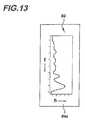
- FIG. 13is a view of a portion of operator interface screen during running of the machine tool showing time dependent values of a device on the machine tool.
- the machine tool control system 20includes an operator interface or control 80 with an operator user terminal 80 having an input device 82 and a visual display device 84 having a programmer screen, and a hard drive data storage device 22 .
- Storage device 22may comprise any device for storing electronic data (including computer programs), such as a semiconductor chip, a read-only memory, magnetic media such as a diskette or computer hard drive, or optical media such as a CD or DVD ROM.
- the storage devicemay be local to the operator interface 80 or may be available over a network.
- Operator interface control 24includes a microprocessor for executing programs and other operations described below, as well as any required memory for programs, data and other information required for executing its tasks.
- the control systemis connected to a machine tool 70 to be controlled.
- Such machine tool 70may be any computer numerically controlled (CNC) or otherwise programmable machine tools such as a grinder, lathe, broach, drill, gear shaper, hobbing machine, hone, milling machine, shaper, or any other machine tool that uses single or multiple edge cutting tools, grinding or electrical discharge machining (EDM).
- CNC machinesgenerally employ a programming language known as G-code to control the tool.
- the system 20preferably requires users to login on input device 82 with their name and password before the machine can be operated.
- Input device 82may include a keyboard terminal as well as a graphical user interface on a terminal display used with a mouse, touch pad or touch sensitive screen.
- a disk 22 filelists users, their passwords, and their access levels, which are transmitted to a user data memory section 28 accessed by a verification program 30 on interface controller 24 .
- the systemchecks user login information against the user, password and access level information from the disk file, and limits the operator's use of the available control functions according to the indicated access level.
- the systemthen outputs the time and aforementioned login data 34 to the user display 84 , and saves a history record of such time and login data to disk storage 22 .
- the system controlmay be configured for different user levels, such as machine tool operator, setup, maintenance, programmer, and engineer, with different restrictions on the types of functions or interactions permitted to each user level.
- disk storage 22Also available from disk storage 22 are configuration and setup files containing data on the machine tool 70 and the different devices thereon, which information may be transferred into memory 26 on interface control 24 at the time the system is started up. This data is then available during subsequent setup and running of the machine tool.
- system 20after login when system 20 initially starts it reads files on disk drive 22 to determine what information to display to the user relative to the machine tool 70 being controlled.
- the fileslist any hardware and software that were purchased with the machine tool, as well as features of the system that can be pre-configured by the user. Preferably, the system only displays information relating to the use of the purchased items as configured. In an automatic configuration mode, the system may also list the paths available on the machine (i.e., simultaneous separate sequences of operation of the different devices that are separately controllable), the different axes of the devices, and the units of measure to be used.
- the filesalso include the latest version of the part program, which includes the data for the part to be produced and the steps needed by the machine to make the part, and will be described further below.
- machine tool 70 controlled by the system of the present inventionis one that includes a numerical control (NC) module 50 and a programmable machine control (PMC) module 60 controlling the tool, such as those made under the Fanuc brand by General Electric Company of Fairfield, Conn.
- the PMC module 60accesses the drives that run the motors and moves the slides and other devices on the machine tool, and handles the digital and analog inputs and outputs to the different devices on the machine tool.
- the NC module 50contains the G-code interpreter that performs the calculations and interpolations and, in conjunction with the PMC module, commands the required movements on the machine tool.
- a library 38 stored on the operator interface control 24contains software routines that interface with and provide direction to the NC and PMC modules, 50 , 60 .
- the programmer software 42is an executable program when it is commanded by the operator interface 24 as a result of operator input via user terminal 80 .
- This programmer softwarewhose operation will be explained further below, enables the operator user to easily program the desired commands and their sequence into the machine tool. It does so by creating a part program, which is stored as a copy in the working program memory 35 . On start up, the latest version of the part program from disk storage 22 is loaded to both programmer software 42 and memory 35 .
- the programmer software 42(including the algorithm for drawing control lines described below) and part program, as well as the other methods for controlling a machine tool described herein, may be implemented by a computer program or software incorporating the process steps and instructions described above in otherwise conventional program code and stored on an otherwise conventional program storage device of the types described above.
- the working part program in memory 35may store modifications that can be transmitted to disk storage 22 , based on any changes permitted by the different user levels. Such modifications will also be transmitted to programmer software 42 with the remainder of the part program from disk 22 .
- Disk 22may store part manufacturing programs specific to the machine tool being used and to the part being machined, including the latest program previously received from the controller memory 35 . After the operator user inputs to the working program structure 35 such information as desired program name, such saved programs may then be loaded into the working program structure in memory 35 , and optionally renamed.
- Operation setup using the terminal 80requires input by the operator of the desired operations and sequence to be performed by machine tool 70 .
- Theseinclude per path cycle programs, i.e., sequence of operations, that command each different and separately programmable device (or path) available on the machine tool.
- Also inputis the particular device set up, and the operation setup for that device.
- the device or tool setupwould include establishing parameters for tool offsets; new wheel dressing; used wheel definition; manual operation of slides such as per axis reference setting, per axis slide jog, per axis handwheel jog and per axis incremental feed; and manual operation of devices such as dressing and loading.
- userscan manually move the axes of the machine to define exact positions at which selected operations will be required to execute during automatic operation.
- the operator userinputs to the working program structure 35 such information as verification of tool device positions.
- the program 35displays to the user on terminal 80 such information as cycle grid and selection, operation details table, position captures and simulation commands.
- selected cyclesusers are also able to set selected operations to be skipped in the sequence during automatic operation.
- the method and system of the present inventionfacilitate automatic machine control as groups of frequently repeated sequences of specific operations, referred to as cycles.
- cyclescollections of cycles required for the machine tool to produce particular parts are referred to as part programs.
- Information for automatic controlis organized in a hierarchical format.
- Part programsare typically made up of one or more cycles.
- Each of the sequence of operationscontains details defining what the machine is to do, when, how, and with what.
- the cycles needed, their respective sequences of operations, and all the operational detailsmay be entered into the control system 20 by the user, and saved on disk storage 22 for later use.
- the method and system of machine tool control of the present inventionsupports frequently used tool, operation and other setup functions via a graphical display of the sequence of operations contained in the currently selected cycle, along with a representation of the details associated with any selected function from the graphical or visual display 84 .
- the programmer software 42 loaded into working program structure 35accesses the configuration and setup files 26 containing the machine tool data ( FIG. 1 ) in the operator interface control 24 , and generates the flowchart images on programmer screen described below.
- the part program from disk 22 loaded into working program structure 35may be modified by the device set up, operation setup and other inputs from user terminal 80 in creating a desired part program for the machine tool. Any devices that are on the machine tool, or that are later added to the machine tool, can be accommodated by the control system of the present invention.
- the programmer screendisplays a menu of the devices available to be programmed on the machine tool.
- a menualso includes images of icons of templates of specific operations to be performed by the devices on the machine tool, or commands for cycles, i.e., often-repeated sequences of specific operations.
- These available listed command templatesmay be copied by the user from the menu portion of the display screen to the working portion in the desired sequence of the operations or cycles to create a part program for a selected machine tool device.
- the usermay also create custom-designed cycles designating new sequences of specific operations, and create command icons for such cycles. These commands are then selected along with the other listed commands.
- the operator userdesignates the sequence in which the commands for the part program are to be executed by the machine tool.
- the iconsmay be designated in a particular sequence even if they are not arranged in that sequence.
- FIGS. 3-5show a sequence of programmer screens illustrating creation and modification of a flowchart of operations to be programmed for execution by the machine tool.
- Screen 84has a left portion 84 a containing a “toolbox” menu 92 of icons representing types of machine device operations that can be inserted into the flowchart.
- Right screen portion 84 cshows a device operation data display 96 that includes a drop-down list of the types of machine tool devices available, and the particular instruction for the selected device, DEV 1 , DEV 2 , DEV 3 , . . . DEVN. Every device-type operation has a drop down list in its template. The contents of the drop down list comprise the various devices on the machine.
- toolbox menu 92lists icons representing machine operations time 92 a , event 92 b , route 92 c , decision 92 d , user 92 e , sub 92 f, toggle 92 g and spindle 92 h .
- Flowchart 94lists in sequence a series of icons representing operations to be performed by the machine tool, start retract 94 a , back off x-axis 94 b , shut off wheel 94 c , shut off cooling 94 d , move z-axis home 94 e and end retract 94 f.
- the userTo select the operation insertion point into the flowchart, for example, by adding another operation into the middle of the existing sequence of flowchart 96 , the user first highlights the operation to follow the new inserted operation, as shown in FIG. 3 by highlighted operation 94 e . As shown in FIG. 4 , the user selects a device type operation desired to be inserted, here toggle operation 92 g , for example by clicking a cursor over the icon in screen portion 84 a . A corresponding icon 94 g is then created in flowchart 96 between operations 94 d and 94 e , and the user is prompted to insert the device operation command. To do so, the user selects from device operation data menu 96 the desired specific operation to be performed by the specific device. In FIG.
- shut off dress coolant operationhere by cursor click selection from a drop-down menu in screen portion 84 c , and the copying of that operation into icon 96 g in flowchart 96 .
- the new sequence of operations represented in the modified flowchart 96may then be executed by the machine tool, as discussed further below.
- the system of the present inventionincludes a sequence generator algorithm or program to provide sequential ordering of the command functions.
- the sequence generator algorithmcreates on display screen 84 a visual part program flowchart for the operator user to see, which flowchart includes connector line generation to connect the desired sequence of commands. For example, the operator may select an icon to connect from, and another icon to connect to, and the algorithm creates the line connecting the two.
- Connector linesare dynamically generated between the selected commands without the need for the user to specify the path they take through the arrangement of icons on programmer screen 84 . These connector lines 66 are shown in FIGS. 3-5 .
- the path-finding algorithmconstructs connector lines that normally avoid the icon blocks themselves in the flowchart, so that the lines extend around the icons whenever possible. If necessary, the algorithm will reposition icons to facilitate drawing of the connector lines.
- FIGS. 6-8depict a programming sequence in conjunction with operation of the algorithm that creates the line connecting the command icons.
- flowchart 94 in screen working portion 84 bshows the sequence of icons 94 h - 94 s as connected by lines 66 .
- the userhas selected and highlighted decision operation 92 d in menu portion 84 a for insertion in front of highlighted operation 94 n .
- the drop-down list of registers available for switching program flowi.e., branching, is also drawn from the setup file at start up.
- the number of such registersis unlimited, and their kind is limited only in the requirement that they be tied to a PMC address so that their value can be read while the machine tool executes the part program.
- FIG. 1the drop-down list of registers available for switching program flow
- the programmer software 42has inserted the selected decision operation as icon 94 t between command icons 94 m and 94 n .
- the programmer softwarecauses both the true (T) 66 b and the false (F) 66 a connector line branches to point to the immediately following operation 94 n .
- the userwill typically want to change one of those branches to point to some other operation, as depicted below.
- the userwill fill in the data for their newly inserted decision operation 94 t by dropping down the selection box 96 , which in this case offers a selection of registers that depict binary data that can change or be changed as the machine runs, here shown as the state of selector switches SEL 1 , SEL 2 on the machine. Other kinds of registers may also be supported.
- one of the decision branches 66 a , 66 bneeds to be moved.
- the userhighlights a portion 65 of the connector line 66 b for the true (T) branch and clicks the delete soft key 92 h in menu portion 84 a , which causes the programmer software to delete the selected connector line 66 b .
- the userhighlights the decision operation 94 t where the new line connector is to start, then clicks the connect soft key 92 e in menu portion 84 a .
- the userclicks the destination operation 94 p , and the control line algorithm draws the connecting line 66 c from icon 94 t to icon 94 p .
- the algorithmdraws the connector line 66 c without crossing any icons.
- Line connectorscan route upward to earlier operations in the sequence as well as downward to later ones.
- the icon for operation command 94 ehas a plus sign 67 on it, indicating that it is a compound operation.
- the usermay click the plus sign to see the operations or sub-program that the compound operation icon 94 e represents.
- the userhas clicked on the plus sign, and causes the programmer software 42 to reveal that compound operation 94 e contains a short sub-program, i.e., a flowcharted sequence of icons 94 e 1 , 94 e 2 , 94 e 3 , 94 e 4 , representing operation commands.
- the dotted line 69 surrounding the sub-program sequence 94 eindicates the parent compound operation, and the operations 94 e 1 , 94 e 2 , 94 e 3 , 94 e 4 in the sub-program are the child operations.
- the previous plus signis now shown as a minus sign 67 ′ that can also be clicked to return to the previous view.
- subroutinesAnother way to employ sub-programs in the present invention is to write them as separate flowcharts, referred to as subroutines.
- operation 94 qis a subroutine call
- menu 96 on the right portion 84 c of the screenshows the name SUBR 1 of the subroutine cycle that is called.
- the usercan access the subroutine flowchart by selecting it from a list on a screen menu, and view the sequence of operation commands, as indicated by icons 94 u - 94 z in FIG. 10 .
- executionis transferred to the indicated sub-routine in FIG.
- the programmer screen 84therefore provides a selection grid of displayed icons in a flowchart, each with a scrollable operation sequence, operation details, and subprogram navigation. Users can navigate the graphically displayed designated sequence of icons by scrolling and clicking operations using a mouse or touch pad, by touching the touch-screen, or by any other input options available on user terminal 80 . Additionally, users can jump to and from pre-designated sub-cycles by hyperlinking icons on the screen.
- the programmer softwareincludes a sequence generator to indicate sequential ordering of the command functions represented by the sequence of images in the flowchart on the screen.
- the usermay simulate any manual motions of the machine tool, or any automatic cycle selected, prior to running the part program flowchart on the machine tool.
- Tool offset structurerefers to the portion of the machine tool, or tooling fixture that holds the workpiece. Machine tools may use different tooling fixtures with the same cutting or grinding tool, or different cutting or grinding tools with the same tooling fixture, and consequently relative positioning between the cutting or grinding tool may be different for each combination. These different positioning values are referred to as tool offsets.
- the tool offsetsmay be stored in a startup file on disk storage 22 a for subsequent reference.
- Final programming of the part program flowchartis performed by the working program structure 35 in controller 24 .
- programmingis accomplished with two modules, a client 46 and a server 48 .
- Both the client computer and the server computermay be located in the operator interface control 24 .
- Server-client communicationuses the http based XML-RPC protocol.
- the client computerruns the programmer software 42 that includes a connector line path find algorithm, and a connector line drawing algorithm, to presents the part program flowchart on the user terminal programmer screen, as described above.
- the client 46then forwards the sequence of user generated commands to the server 48 .
- the programmer software 42 on client computermay run independently from the remainder of the operator interface control 24 , and may access connections to and communicate with workstations via conventional Ethernet or other network connections, either at the facility running the machine tool or elsewhere via the Internet.
- the programmer software 42 that creates the part program to be run on the machine toolmay be run off line from the operator interface control 24 and machine tool, with or without the code conversion described below.
- An XML program file accessed by the serverknown as the template file 54 , contains descriptions of program elements that will be added to the program file. Templates are interpreted real time, and allow for dynamic construction of final program elements, depending on the contexts of elements already written and the configuration files 56 .
- the server 48then handles the assembling of the XML program 52 in a text format based on the sequenced graphical format based flowchart commands generated in the client.
- Compiler module 40takes the flowchart of sequenced commands from programmer screen 84 , which is in XML text format, and converts it to G-code for transfer to NC module 50 .
- the operator interface controller 24subsequently commands compiler 40 to transmit the translated XML program, now in G-Code or other machine language, to the NC module 50 by means of routines stored in library 38 .
- Tool offset datais also transferred to the NC module 50 by routines store in library 38 .
- routines from library 38transmit commands to the NC module 50 and PMC module 60 to operate and control machine tool 60 .
- NC module 50transfers position and other machine information to the operator interface 24 by means of routines from library 38 .
- the PMC moduletransmits machine status information to the operator interface 24 by means of routines in library 38 .
- the present machine tool control systempreferrably generates a relative position display consisting of a list of the axes on the machine and a number showing the position of each, visible on display 84 . Any one of these displayed positions can be selected, and then set by the user to any desired value. Subsequent movement of the axis, typically via manual commands from the user, are reflected by changes in the displayed number associated with said axis, such that the distance the slide moves is accurately indicated by the number. This permits the machine to be used as a sophisticated measuring device, accurate to the resolutions of the axis feedback.
- FIG. 12shows a portion 84 d of a programmer screen showing the operation sequence, established by the previously described flowchart, as it is run on the machine tool.
- the sequence of commands 98is shown on the screen as a stack of boxes OP 1 , OP 2 , OP 3 , OP 4 , OP 5 . . . OPN, with the currently executed operation OP 5 indicated by block 99 .
- the stack 98scrolls upward, as indicated by arrow 97 , so that the operations adjacent to the current operation are displayed.
- the displaywill show the operation sequence for each different path (i.e., device) simultaneously on the screen. Adjacent to the current operation is displayed a counter showing the time the operation has taken since it began. Also shown for each path is runtime data such as throughput (e.g., last and current elapsed cycle time, part counters (e.g., resettable and total), process data (e.g., feed rate, rate override, wheel remaining, dress counter), and spindle data (e.g., wheel speed, work speed, current wheel power).
- throughpute.g., last and current elapsed cycle time, part counters (e.g., resettable and total)
- process datae.g., feed rate, rate override, wheel remaining, dress counter
- spindle datae.g., wheel speed, work speed, current wheel power
- the present inventionalso preferably includes a strip chart-like display of a continuously scrolling rectangular field upon which there is drawn one or more lines or bars that reflect the changing values, compared to a horizontal scale, of data or corresponding inputs to the control.
- An example of the strip chart displayis shown in FIG. 13 .
- Programmer screen portion 84 gshows strip chart 90 showing values of spindle horsepower, for example, on the horizontal axis h as a function of time value t on the vertical axis.
- the effectis one of a time-based line or bar graph.
- the vertical scrolling speedis adjustable by the operator, in effect becoming an adjustment of the time scale of the graph.
- the strip chartcan be configured to display the values of various inputs, and its parameters, such as the horizontal and vertical scales, the background and foreground colors, or the type of line or bar, can all be adjusted by the user.
- the usermay utilize a size correcting function to offset the axis position(s) of specified operations so as to correct the resultant work-pieces back to within the specified limits.
- Any pertaining documentary files stored on storage disks accessible by the operator interface controlcan be viewed by users on the display screen, including text files and Auto-Cad drawings. These can be configured as hyperlink targets and accessed quickly from help screens available to the operator user on display 84 .
- the systemmay also display information related to the context from which the request is made, as well as a hyperlinking table of contents. When employed, the operator user is initially hyperlinked and zoomed in to the specific position in the file, to provide context sensitive help.
- Machine alarms indicating machine tool problemsmay be listed in a text file read by the operator interface control. As alarms occur they are displayed on the screen and appropriate options are made available to the user. All alarms are logged in a separate file, along with the time and date they occurred.
- the operator interface controlcan display this history log in a grid that allows sorting of the entries by alarm name, or by time or date of occurrence.
- a similar history logis created for cycle logs storing all of the past machine operations. So that the alarm and cycle histories do not use up excessive storage space, the operator user may limit the number and size of each history file and the number of alarms stored in each of the history files. When the number of history files is exceeded in each category, ie., alarm log or cycle log, the oldest history file is overwritten.
- the present inventionprovides a machine tool control system that reduces the complexity of programs required for inputting information and commands, and increases flexibility of creating and using programmed cycles of commands.
- the machine tool control systemis able to access substantially all of the devices on the machine tool, and is able to be used on a variety of different machine tools.
Landscapes
- Engineering & Computer Science (AREA)
- Physics & Mathematics (AREA)
- General Physics & Mathematics (AREA)
- Automation & Control Theory (AREA)
- Human Computer Interaction (AREA)
- Manufacturing & Machinery (AREA)
- Numerical Control (AREA)
Abstract
Description
Claims (25)
Priority Applications (1)
| Application Number | Priority Date | Filing Date | Title |
|---|---|---|---|
| US11/767,184US7949422B1 (en) | 2007-06-22 | 2007-06-22 | Machine tool control system |
Applications Claiming Priority (1)
| Application Number | Priority Date | Filing Date | Title |
|---|---|---|---|
| US11/767,184US7949422B1 (en) | 2007-06-22 | 2007-06-22 | Machine tool control system |
Publications (1)
| Publication Number | Publication Date |
|---|---|
| US7949422B1true US7949422B1 (en) | 2011-05-24 |
Family
ID=44022284
Family Applications (1)
| Application Number | Title | Priority Date | Filing Date |
|---|---|---|---|
| US11/767,184Expired - Fee RelatedUS7949422B1 (en) | 2007-06-22 | 2007-06-22 | Machine tool control system |
Country Status (1)
| Country | Link |
|---|---|
| US (1) | US7949422B1 (en) |
Cited By (26)
| Publication number | Priority date | Publication date | Assignee | Title |
|---|---|---|---|---|
| US20100063608A1 (en)* | 2008-09-11 | 2010-03-11 | Miller John W | Method and System for Programmable Numerical Control |
| US20100268357A1 (en)* | 2009-04-21 | 2010-10-21 | Foxnum Technology Co., Ltd. | Compiler for drilling machine |
| US20110191760A1 (en)* | 2010-01-29 | 2011-08-04 | Nathaniel Guy | Method and apparatus for enhancing comprehension of code time complexity and flow |
| US8061036B1 (en)* | 2010-07-23 | 2011-11-22 | Glasscraft Door Company | Method for making a window with a decorative security panel |
| US8141833B1 (en) | 2010-07-23 | 2012-03-27 | Glasscraft Door Company | Connector for connecting grilles to doors |
| US8146304B1 (en) | 2010-07-23 | 2012-04-03 | Glasscraft Door Company | Grille assembly for doors and method for making |
| US8171644B1 (en) | 2010-07-23 | 2012-05-08 | Glasscraft Door Company | Method for making a door with a decorative security panel |
| US8171643B1 (en) | 2010-07-23 | 2012-05-08 | Glasscraft Door Company | Method for making a decorative security panel for doors and windows |
| US20130166068A1 (en)* | 2011-12-22 | 2013-06-27 | Fanuc Robotics America Corporation | Numerical control program execution by robot |
| CN103186113A (en)* | 2011-12-28 | 2013-07-03 | 赐福科技股份有限公司 | Numerical control machine tool and control method thereof |
| US20130257738A1 (en)* | 2010-12-02 | 2013-10-03 | Mitsubishi Electric Corporation | Numerical control apparatus |
| US20130338815A1 (en)* | 2012-06-15 | 2013-12-19 | Fanuc Corporation | Numerical controller for displaying virtual control panel |
| WO2014146717A1 (en)* | 2013-03-21 | 2014-09-25 | Siemens Aktiengesellschaft | Configuration of an operational procedure of a process and/or production system |
| EP2790076A1 (en)* | 2013-04-10 | 2014-10-15 | Siemens Aktiengesellschaft | Method for operating a production or machine tool, computer program for implementing the method and operating device with such a computer program |
| US20150290759A1 (en)* | 2014-04-14 | 2015-10-15 | Nakamura-Tome Precision Industry Co., Ltd. | Machine state display device of composite lathe having a plurality of main spindles |
| US20160085235A1 (en)* | 2014-09-24 | 2016-03-24 | Fanuc Corporation | Numerical control device |
| US20160085418A1 (en)* | 2014-09-23 | 2016-03-24 | Environmental Intellect, Llc | Graphical User Interface Systems and Methods for Data Integration with Data-Driven Engineering Drawings |
| US20160246279A1 (en)* | 2013-11-20 | 2016-08-25 | Mitsubishi Electric Corporation | Sequence-program-creation supporting apparatus |
| US20160341076A1 (en)* | 2015-05-22 | 2016-11-24 | Kabushiki Kaisha Toshiba | Plant operation apparatus, plant operation method, and plant operation program |
| CN106502206A (en)* | 2016-12-16 | 2017-03-15 | 南京九致信息科技有限公司 | Digit Control Machine Tool and the method for operating numerical control lathe |
| EP3068038A4 (en)* | 2013-11-05 | 2017-12-20 | Kabushiki Kaisha Yaskawa Denki | Trace data collection system, controller, motor control device, operation terminal, and trace data collection method |
| US20190310815A1 (en)* | 2018-04-05 | 2019-10-10 | Fanuc Corporation | Display device |
| US10481582B2 (en)* | 2012-02-15 | 2019-11-19 | Citizen Watch Co., Ltd | Process for controlling a machine tool |
| US20200117161A1 (en)* | 2018-10-12 | 2020-04-16 | Industrial Technology Research Institute | Matching recognition method and system for nc program and corresponding cutting tools of machine tools |
| US11243676B2 (en)* | 2014-10-22 | 2022-02-08 | Okuma Corporation | Numerical control system for machine tool |
| US20220342374A1 (en)* | 2019-10-10 | 2022-10-27 | Siemens Aktiengesellschaft | Auto-Generated Modular Connectors For Automation Ecosystem Integration |
Citations (40)
| Publication number | Priority date | Publication date | Assignee | Title |
|---|---|---|---|---|
| US4455619A (en)* | 1980-05-30 | 1984-06-19 | Hitachi, Ltd. | Interactive equipment for computer programming by linkage of labeled block representations of arithmetic/logical subprograms |
| US4852047A (en)* | 1987-04-14 | 1989-07-25 | Universal Automation Inc. | Continuous flow chart, improved data format and debugging system for programming and operation of machines |
| US5437007A (en)* | 1992-11-10 | 1995-07-25 | Hewlett-Packard Company | Control sequencer in an iconic programming system |
| US5465215A (en)* | 1994-07-07 | 1995-11-07 | Cincinnati Milacron Inc. | Numerical control method and apparatus |
| US5485620A (en)* | 1994-02-25 | 1996-01-16 | Automation System And Products, Inc. | Integrated control system for industrial automation applications |
| US5619694A (en)* | 1993-08-26 | 1997-04-08 | Nec Corporation | Case database storage/retrieval system |
| US5715429A (en)* | 1991-09-13 | 1998-02-03 | Mitsubishi Denki Kabushiki Kaisha | Positioning and control apparatus that is interactively programmable using a display |
| US5732277A (en)* | 1986-10-24 | 1998-03-24 | National Instruments Corporation | Graphical system for modelling a process and associated method |
| US5862379A (en)* | 1995-03-07 | 1999-01-19 | International Business Machines Corporation | Visual programming tool for developing software applications |
| US5896290A (en)* | 1995-03-31 | 1999-04-20 | Toshiba Kikai Kabushiki Kaisha | Man-machine interface system for a process controller |
| US5933353A (en)* | 1997-09-16 | 1999-08-03 | New Focus, Inc. | Method and apparatus for computer aided machining |
| US5940294A (en)* | 1996-04-12 | 1999-08-17 | Fisher-Rosemont Systems, Inc. | System for assisting configuring a process control environment |
| US5940296A (en)* | 1995-11-06 | 1999-08-17 | Medar Inc. | Method and system for interactively developing a graphical control-flow structure and associated application software for use in a machine vision system |
| US6055369A (en)* | 1997-05-06 | 2000-04-25 | Hitachi Software Engineering Co., Ltd. | Apparatus for visual programming with screen flow |
| US6112133A (en)* | 1998-02-27 | 2000-08-29 | Imcs, Inc. | Visual system and method for generating a CNC program for machining parts with planar and curvilinear surfaces |
| US6236399B1 (en)* | 1997-02-26 | 2001-05-22 | Amada Company, Limited | Display method for information setting screen along process flow and a multi-window type NC apparatus having such function |
| US6298474B1 (en)* | 1999-04-30 | 2001-10-02 | Intergral Vision, Inc. | Method and system for interactively developing a graphical control-flow structure and associated application software for use in a machine vision system and computer-readable storage medium having a program for executing the method |
| US6366300B1 (en)* | 1997-03-11 | 2002-04-02 | Mitsubishi Denki Kabushiki Kaisha | Visual programming method and its system |
| US20020054099A1 (en)* | 2000-08-07 | 2002-05-09 | Regina Schmitt | Flowchart programming for industrial controllers, in particular motion controllers |
| US6421821B1 (en)* | 1999-03-10 | 2002-07-16 | Ronald J. Lavallee | Flow chart-based programming method and system for object-oriented languages |
| US6564368B1 (en)* | 1998-10-01 | 2003-05-13 | Call Center Technology, Inc. | System and method for visual application development without programming |
| US20030222912A1 (en)* | 2002-02-01 | 2003-12-04 | John Fairweather | System and method for managing dataflows |
| US6671572B1 (en)* | 2002-07-09 | 2003-12-30 | Agile Technology Partners, Llc | Method and computer program for automated design and manufacture of custom workholding fixtures requiring machining of substantially unique mounting geometries |
| US6671869B2 (en)* | 2001-12-12 | 2003-12-30 | Scott A. Davidson | Method and apparatus for graphically programming a programmable circuit |
| US6741905B1 (en)* | 2001-02-24 | 2004-05-25 | Imcs, Inc. | Visual system for programming of simultaneous and synchronous machining operations on lathes |
| US6779175B2 (en)* | 2001-05-22 | 2004-08-17 | Thermwood Corporation | Method and system for converting graphic databases into coded workpiece processing programs |
| US6784902B1 (en)* | 1999-09-04 | 2004-08-31 | National Instruments Corporation | Method for configuration and parameterization of a graphical computer program for the operation of a data processing system |
| US6795748B2 (en)* | 2000-04-10 | 2004-09-21 | Siemens Aktiengesellschaft | Input method for programming industrial controllers |
| US6802053B1 (en)* | 1997-08-18 | 2004-10-05 | National Instruments Corporation | Graphical programming system with distributed block diagram execution and front panel display |
| US20040210868A1 (en)* | 2003-02-27 | 2004-10-21 | Siemens Aktiengesellschaft | Icons and icon representation of process steps for graphic visualization of task-oriented steps |
| US6845275B2 (en)* | 2001-08-06 | 2005-01-18 | Entivity, Inc. | Flowchart-based control system with active diagnostic objects |
| US7076332B2 (en)* | 2002-01-18 | 2006-07-11 | National Instruments Corporation | System and method for invoking execution of a sequence of operations that includes motion control, machine vision, and data acquisition (DAQ) functionality |
| US7089531B2 (en)* | 2001-10-04 | 2006-08-08 | Dr. Johannes Heidenhain Gmbh | Method and device for generating or editing NC programs |
| US7155298B2 (en)* | 2001-11-23 | 2006-12-26 | Dr. Johannes Heidenhain Gmbh | Device and method for generating and/or editing NC programs or NC tables |
| US7159183B1 (en)* | 1999-08-19 | 2007-01-02 | National Instruments Corporation | System and method for programmatically creating a graphical program |
| US7308334B2 (en)* | 2001-08-23 | 2007-12-11 | Fei Company | Graphical automated machine control and metrology |
| US7340715B2 (en)* | 2004-03-10 | 2008-03-04 | Hanbai Liu | Visual programming method and system thereof |
| US7367017B2 (en)* | 2001-01-31 | 2008-04-29 | Hewlett-Packard Development Company, L.P. | Method and apparatus for analyzing machine control sequences |
| US7474925B2 (en)* | 2002-04-15 | 2009-01-06 | Peter Renner | System for automation of technical processes |
| US7505817B2 (en)* | 2000-03-06 | 2009-03-17 | Siemens Technology-To-Business Center, Llc | Programming automation by demonstration |
- 2007
- 2007-06-22USUS11/767,184patent/US7949422B1/ennot_activeExpired - Fee Related
Patent Citations (43)
| Publication number | Priority date | Publication date | Assignee | Title |
|---|---|---|---|---|
| US4455619A (en)* | 1980-05-30 | 1984-06-19 | Hitachi, Ltd. | Interactive equipment for computer programming by linkage of labeled block representations of arithmetic/logical subprograms |
| US5732277A (en)* | 1986-10-24 | 1998-03-24 | National Instruments Corporation | Graphical system for modelling a process and associated method |
| US4852047A (en)* | 1987-04-14 | 1989-07-25 | Universal Automation Inc. | Continuous flow chart, improved data format and debugging system for programming and operation of machines |
| US5715429A (en)* | 1991-09-13 | 1998-02-03 | Mitsubishi Denki Kabushiki Kaisha | Positioning and control apparatus that is interactively programmable using a display |
| US5437007A (en)* | 1992-11-10 | 1995-07-25 | Hewlett-Packard Company | Control sequencer in an iconic programming system |
| US5619694A (en)* | 1993-08-26 | 1997-04-08 | Nec Corporation | Case database storage/retrieval system |
| US5485620A (en)* | 1994-02-25 | 1996-01-16 | Automation System And Products, Inc. | Integrated control system for industrial automation applications |
| US5465215A (en)* | 1994-07-07 | 1995-11-07 | Cincinnati Milacron Inc. | Numerical control method and apparatus |
| US5862379A (en)* | 1995-03-07 | 1999-01-19 | International Business Machines Corporation | Visual programming tool for developing software applications |
| US5896290A (en)* | 1995-03-31 | 1999-04-20 | Toshiba Kikai Kabushiki Kaisha | Man-machine interface system for a process controller |
| US5940296A (en)* | 1995-11-06 | 1999-08-17 | Medar Inc. | Method and system for interactively developing a graphical control-flow structure and associated application software for use in a machine vision system |
| US5940294A (en)* | 1996-04-12 | 1999-08-17 | Fisher-Rosemont Systems, Inc. | System for assisting configuring a process control environment |
| US6236399B1 (en)* | 1997-02-26 | 2001-05-22 | Amada Company, Limited | Display method for information setting screen along process flow and a multi-window type NC apparatus having such function |
| US6366300B1 (en)* | 1997-03-11 | 2002-04-02 | Mitsubishi Denki Kabushiki Kaisha | Visual programming method and its system |
| US6055369A (en)* | 1997-05-06 | 2000-04-25 | Hitachi Software Engineering Co., Ltd. | Apparatus for visual programming with screen flow |
| US6802053B1 (en)* | 1997-08-18 | 2004-10-05 | National Instruments Corporation | Graphical programming system with distributed block diagram execution and front panel display |
| US5933353A (en)* | 1997-09-16 | 1999-08-03 | New Focus, Inc. | Method and apparatus for computer aided machining |
| US6112133A (en)* | 1998-02-27 | 2000-08-29 | Imcs, Inc. | Visual system and method for generating a CNC program for machining parts with planar and curvilinear surfaces |
| US6564368B1 (en)* | 1998-10-01 | 2003-05-13 | Call Center Technology, Inc. | System and method for visual application development without programming |
| US6421821B1 (en)* | 1999-03-10 | 2002-07-16 | Ronald J. Lavallee | Flow chart-based programming method and system for object-oriented languages |
| US6298474B1 (en)* | 1999-04-30 | 2001-10-02 | Intergral Vision, Inc. | Method and system for interactively developing a graphical control-flow structure and associated application software for use in a machine vision system and computer-readable storage medium having a program for executing the method |
| US7159183B1 (en)* | 1999-08-19 | 2007-01-02 | National Instruments Corporation | System and method for programmatically creating a graphical program |
| US6784902B1 (en)* | 1999-09-04 | 2004-08-31 | National Instruments Corporation | Method for configuration and parameterization of a graphical computer program for the operation of a data processing system |
| US7505817B2 (en)* | 2000-03-06 | 2009-03-17 | Siemens Technology-To-Business Center, Llc | Programming automation by demonstration |
| US6795748B2 (en)* | 2000-04-10 | 2004-09-21 | Siemens Aktiengesellschaft | Input method for programming industrial controllers |
| US7302676B2 (en)* | 2000-08-07 | 2007-11-27 | Siemens Aktiengesselschaft | Method for debugging flowchart programs for industrial controllers |
| US20020054099A1 (en)* | 2000-08-07 | 2002-05-09 | Regina Schmitt | Flowchart programming for industrial controllers, in particular motion controllers |
| US6981226B2 (en)* | 2000-08-07 | 2005-12-27 | Siemens Aktiengesellschaft | Flowchart programming for industrial controllers, in particular motion controllers |
| US7000191B2 (en)* | 2000-08-07 | 2006-02-14 | Siemens Aktiengesellschaft | Flowchart programming for industrial controllers, in particular motion controllers |
| US7367017B2 (en)* | 2001-01-31 | 2008-04-29 | Hewlett-Packard Development Company, L.P. | Method and apparatus for analyzing machine control sequences |
| US6741905B1 (en)* | 2001-02-24 | 2004-05-25 | Imcs, Inc. | Visual system for programming of simultaneous and synchronous machining operations on lathes |
| US6779175B2 (en)* | 2001-05-22 | 2004-08-17 | Thermwood Corporation | Method and system for converting graphic databases into coded workpiece processing programs |
| US6845275B2 (en)* | 2001-08-06 | 2005-01-18 | Entivity, Inc. | Flowchart-based control system with active diagnostic objects |
| US7308334B2 (en)* | 2001-08-23 | 2007-12-11 | Fei Company | Graphical automated machine control and metrology |
| US7089531B2 (en)* | 2001-10-04 | 2006-08-08 | Dr. Johannes Heidenhain Gmbh | Method and device for generating or editing NC programs |
| US7155298B2 (en)* | 2001-11-23 | 2006-12-26 | Dr. Johannes Heidenhain Gmbh | Device and method for generating and/or editing NC programs or NC tables |
| US6671869B2 (en)* | 2001-12-12 | 2003-12-30 | Scott A. Davidson | Method and apparatus for graphically programming a programmable circuit |
| US7076332B2 (en)* | 2002-01-18 | 2006-07-11 | National Instruments Corporation | System and method for invoking execution of a sequence of operations that includes motion control, machine vision, and data acquisition (DAQ) functionality |
| US20030222912A1 (en)* | 2002-02-01 | 2003-12-04 | John Fairweather | System and method for managing dataflows |
| US7474925B2 (en)* | 2002-04-15 | 2009-01-06 | Peter Renner | System for automation of technical processes |
| US6671572B1 (en)* | 2002-07-09 | 2003-12-30 | Agile Technology Partners, Llc | Method and computer program for automated design and manufacture of custom workholding fixtures requiring machining of substantially unique mounting geometries |
| US20040210868A1 (en)* | 2003-02-27 | 2004-10-21 | Siemens Aktiengesellschaft | Icons and icon representation of process steps for graphic visualization of task-oriented steps |
| US7340715B2 (en)* | 2004-03-10 | 2008-03-04 | Hanbai Liu | Visual programming method and system thereof |
Non-Patent Citations (4)
| Title |
|---|
| Julio Garrido Campos, Martin Hardwick, A traceability information model for CNC manufacturing, Computer-Aided Design, vol. 38, Issue 5, May 2006, pp. 540-551.* |
| Kolluri, S. P. and Tseng, A. A. 1989. Simulation of CNC controller features in graphics-based programming. Computers in Industry. 11, 2 (Jan. 1989), Abstract only.* |
| Mark Albert. (Nov. 1997). Software is the CNC. Modern Machine Shop, 70(6), 60.* |
| X.W. Xu, S.T. Newman, Making CNC machine tools more open, interoperable and intelligent-a review of the technologies, Computers in Industry, vol. 57, Issue 2, Feb. 2006, pp. 141-152.* |
Cited By (41)
| Publication number | Priority date | Publication date | Assignee | Title |
|---|---|---|---|---|
| US20100063608A1 (en)* | 2008-09-11 | 2010-03-11 | Miller John W | Method and System for Programmable Numerical Control |
| US8688258B2 (en)* | 2008-09-11 | 2014-04-01 | Rockwell Automation Technologies, Inc. | Method of controlling a machine tool |
| US9483043B2 (en) | 2008-09-11 | 2016-11-01 | Rockwell Automation Technologies, Inc. | Method and system for programmable numerical control |
| US20100268357A1 (en)* | 2009-04-21 | 2010-10-21 | Foxnum Technology Co., Ltd. | Compiler for drilling machine |
| US20110191760A1 (en)* | 2010-01-29 | 2011-08-04 | Nathaniel Guy | Method and apparatus for enhancing comprehension of code time complexity and flow |
| US8516467B2 (en)* | 2010-01-29 | 2013-08-20 | Nintendo Co., Ltd. | Method and apparatus for enhancing comprehension of code time complexity and flow |
| US8061036B1 (en)* | 2010-07-23 | 2011-11-22 | Glasscraft Door Company | Method for making a window with a decorative security panel |
| US8171643B1 (en) | 2010-07-23 | 2012-05-08 | Glasscraft Door Company | Method for making a decorative security panel for doors and windows |
| US8171644B1 (en) | 2010-07-23 | 2012-05-08 | Glasscraft Door Company | Method for making a door with a decorative security panel |
| US8146304B1 (en) | 2010-07-23 | 2012-04-03 | Glasscraft Door Company | Grille assembly for doors and method for making |
| US8141833B1 (en) | 2010-07-23 | 2012-03-27 | Glasscraft Door Company | Connector for connecting grilles to doors |
| US20130257738A1 (en)* | 2010-12-02 | 2013-10-03 | Mitsubishi Electric Corporation | Numerical control apparatus |
| US20130166068A1 (en)* | 2011-12-22 | 2013-06-27 | Fanuc Robotics America Corporation | Numerical control program execution by robot |
| US9063535B2 (en)* | 2011-12-22 | 2015-06-23 | Fanuc Robotics America Corporation | Numerical control program execution by robot |
| US20130173031A1 (en)* | 2011-12-28 | 2013-07-04 | Foxnum Technology Co., Ltd. | Computer numerical control machine and control method |
| CN103186113A (en)* | 2011-12-28 | 2013-07-03 | 赐福科技股份有限公司 | Numerical control machine tool and control method thereof |
| US10481582B2 (en)* | 2012-02-15 | 2019-11-19 | Citizen Watch Co., Ltd | Process for controlling a machine tool |
| US20130338815A1 (en)* | 2012-06-15 | 2013-12-19 | Fanuc Corporation | Numerical controller for displaying virtual control panel |
| WO2014146717A1 (en)* | 2013-03-21 | 2014-09-25 | Siemens Aktiengesellschaft | Configuration of an operational procedure of a process and/or production system |
| EP2790076A1 (en)* | 2013-04-10 | 2014-10-15 | Siemens Aktiengesellschaft | Method for operating a production or machine tool, computer program for implementing the method and operating device with such a computer program |
| US10248090B2 (en) | 2013-11-05 | 2019-04-02 | Kabushiki Kaisha Yaskawa Denki | Trace data collection system, controller, motor control device, operation terminal, and trace data collection method |
| EP3068038A4 (en)* | 2013-11-05 | 2017-12-20 | Kabushiki Kaisha Yaskawa Denki | Trace data collection system, controller, motor control device, operation terminal, and trace data collection method |
| US10203681B2 (en)* | 2013-11-20 | 2019-02-12 | Mistubishi Electric Corporation | Sequence-program-creation supporting apparatus |
| US20160246279A1 (en)* | 2013-11-20 | 2016-08-25 | Mitsubishi Electric Corporation | Sequence-program-creation supporting apparatus |
| US20150290759A1 (en)* | 2014-04-14 | 2015-10-15 | Nakamura-Tome Precision Industry Co., Ltd. | Machine state display device of composite lathe having a plurality of main spindles |
| US20160085418A1 (en)* | 2014-09-23 | 2016-03-24 | Environmental Intellect, Llc | Graphical User Interface Systems and Methods for Data Integration with Data-Driven Engineering Drawings |
| US10599307B2 (en)* | 2014-09-23 | 2020-03-24 | Environmental Intellect, Llc | Graphical user interface systems and methods for data integration with data-driven engineering drawings |
| US9811251B2 (en)* | 2014-09-23 | 2017-11-07 | Environmental Intellect, Llc | Graphical user interface systems and methods for data integration with data-driven engineering drawings |
| US20180121058A1 (en)* | 2014-09-23 | 2018-05-03 | Environmental Intellect, Llc | Graphical user interface systems and methods for data integration with data-driven engineering drawings |
| US20160085235A1 (en)* | 2014-09-24 | 2016-03-24 | Fanuc Corporation | Numerical control device |
| US10162334B2 (en)* | 2014-09-24 | 2018-12-25 | Fanuc Corporation | Numerical control device |
| US11243676B2 (en)* | 2014-10-22 | 2022-02-08 | Okuma Corporation | Numerical control system for machine tool |
| US20160341076A1 (en)* | 2015-05-22 | 2016-11-24 | Kabushiki Kaisha Toshiba | Plant operation apparatus, plant operation method, and plant operation program |
| JP2016218845A (en)* | 2015-05-22 | 2016-12-22 | 株式会社東芝 | PLANT OPERATION DEVICE, PLANT OPERATION METHOD, AND PLANT OPERATION PROGRAM |
| US10809684B2 (en)* | 2015-05-22 | 2020-10-20 | Kabushiki Kaisha Toshiba | Plant operation apparatus, plant operation method, and plant operation program |
| CN106502206A (en)* | 2016-12-16 | 2017-03-15 | 南京九致信息科技有限公司 | Digit Control Machine Tool and the method for operating numerical control lathe |
| US20190310815A1 (en)* | 2018-04-05 | 2019-10-10 | Fanuc Corporation | Display device |
| US10802781B2 (en)* | 2018-04-05 | 2020-10-13 | Fanuc Corporation | Display device |
| US20200117161A1 (en)* | 2018-10-12 | 2020-04-16 | Industrial Technology Research Institute | Matching recognition method and system for nc program and corresponding cutting tools of machine tools |
| US10705501B2 (en)* | 2018-10-12 | 2020-07-07 | Industrial Technology Research Institute | Matching recognition method and system for NC program and corresponding cutting tools of machine tools |
| US20220342374A1 (en)* | 2019-10-10 | 2022-10-27 | Siemens Aktiengesellschaft | Auto-Generated Modular Connectors For Automation Ecosystem Integration |
Similar Documents
| Publication | Publication Date | Title |
|---|---|---|
| US7949422B1 (en) | Machine tool control system | |
| US7076322B2 (en) | System and method for satisfying move constraints when performing a motion control sequence | |
| US8688258B2 (en) | Method of controlling a machine tool | |
| US8588955B2 (en) | Method and apparatus for optimizing, monitoring, or analyzing a process | |
| US4587608A (en) | Method of automatically creating numerical control data in one of a plurality of data formats | |
| JP5414948B1 (en) | Numerical controller | |
| US5321603A (en) | Programming apparatus for an industrial controller using two-dimensional graphic behavior profiles | |
| US11402818B2 (en) | Numerical controller and data structure | |
| JP6261613B2 (en) | Machine tool controller | |
| JP6549683B2 (en) | Control device | |
| US5315503A (en) | Numerical control apparatus having a teaching function and a method of teaching a machining program thereby | |
| KR20120085420A (en) | Cutting shape input apparatus and method using interactive program in computer numarical control machine tools | |
| JP2021043771A (en) | Information processing device | |
| JP6638979B2 (en) | Numerical control device with machining process management function and machining process management program | |
| CN112805638A (en) | NC program conversion processing method and conversion computer | |
| US7089531B2 (en) | Method and device for generating or editing NC programs | |
| KR20110137651A (en) | Part Programmer for Complex Lathe and Synchronization Program between Complex Processes | |
| JP7218459B1 (en) | Information processing equipment, machine tools and information processing programs | |
| JP2002529843A5 (en) | ||
| US20220342381A1 (en) | Managing a machine tool method, for example method of mapping toolpath data and machine code, a control device, and a machine tool | |
| Basheer et al. | CNC Software Control System Using Visual Basic | |
| Martinova et al. | Development of a cross-platform software application for programming CNC machine tools | |
| Dai et al. | PIN-a PC-based robot simulation and offline programming system using macro programming techniques | |
| US20250076853A1 (en) | Method for operating a numerically controlled machine tool | |
| KR102455108B1 (en) | Application recommendation methods for machine tools |
Legal Events
| Date | Code | Title | Description |
|---|---|---|---|
| AS | Assignment | Owner name:VERMONT MACHINE TOOL CORPORATION, VERMONT Free format text:ASSIGNMENT OF ASSIGNORS INTEREST;ASSIGNORS:LITTLE, ROBBY J.;RAMEN, JEFFREY P.;LAUZON, DAVID W.;AND OTHERS;SIGNING DATES FROM 20070626 TO 20070627;REEL/FRAME:019629/0058 | |
| STCF | Information on status: patent grant | Free format text:PATENTED CASE | |
| REMI | Maintenance fee reminder mailed | ||
| FPAY | Fee payment | Year of fee payment:4 | |
| SULP | Surcharge for late payment | ||
| AS | Assignment | Owner name:FIVES LANDIS CORP., MARYLAND Free format text:ASSIGNMENT OF ASSIGNORS INTEREST;ASSIGNOR:VERMONT MACHINE TOOL CORPORATION;REEL/FRAME:039981/0036 Effective date:20150717 | |
| MAFP | Maintenance fee payment | Free format text:PAYMENT OF MAINTENANCE FEE, 8TH YEAR, LARGE ENTITY (ORIGINAL EVENT CODE: M1552); ENTITY STATUS OF PATENT OWNER: LARGE ENTITY Year of fee payment:8 | |
| FEPP | Fee payment procedure | Free format text:MAINTENANCE FEE REMINDER MAILED (ORIGINAL EVENT CODE: REM.); ENTITY STATUS OF PATENT OWNER: LARGE ENTITY | |
| LAPS | Lapse for failure to pay maintenance fees | Free format text:PATENT EXPIRED FOR FAILURE TO PAY MAINTENANCE FEES (ORIGINAL EVENT CODE: EXP.); ENTITY STATUS OF PATENT OWNER: LARGE ENTITY | |
| STCH | Information on status: patent discontinuation | Free format text:PATENT EXPIRED DUE TO NONPAYMENT OF MAINTENANCE FEES UNDER 37 CFR 1.362 | |
| FP | Lapsed due to failure to pay maintenance fee | Effective date:20230524 |