US7948559B2 - Method and apparatus for lipsync measurement and correction - Google Patents
Method and apparatus for lipsync measurement and correctionDownload PDFInfo
- Publication number
- US7948559B2 US7948559B2US11/784,758US78475807AUS7948559B2US 7948559 B2US7948559 B2US 7948559B2US 78475807 AUS78475807 AUS 78475807AUS 7948559 B2US7948559 B2US 7948559B2
- Authority
- US
- United States
- Prior art keywords
- audio
- media program
- silence
- program signal
- signal
- Prior art date
- Legal status (The legal status is an assumption and is not a legal conclusion. Google has not performed a legal analysis and makes no representation as to the accuracy of the status listed.)
- Active, expires
Links
- 238000000034methodMethods0.000titleclaimsabstractdescription30
- 238000012937correctionMethods0.000titledescription3
- 238000005259measurementMethods0.000titledescription3
- 230000005236sound signalEffects0.000claimsdescription15
- 238000001914filtrationMethods0.000claimsdescription9
- 230000001755vocal effectEffects0.000claimsdescription6
- 238000010586diagramMethods0.000description6
- 230000008569processEffects0.000description5
- 238000012986modificationMethods0.000description3
- 230000004048modificationEffects0.000description3
- 230000003111delayed effectEffects0.000description2
- 238000001228spectrumMethods0.000description2
- 238000007619statistical methodMethods0.000description2
- 230000001360synchronised effectEffects0.000description2
- 238000009825accumulationMethods0.000description1
- 238000004458analytical methodMethods0.000description1
- 230000008901benefitEffects0.000description1
- 238000012512characterization methodMethods0.000description1
- 239000002131composite materialSubstances0.000description1
- 238000013461designMethods0.000description1
- 230000000694effectsEffects0.000description1
- 238000004519manufacturing processMethods0.000description1
- 239000000203mixtureSubstances0.000description1
Images


Classifications
- H—ELECTRICITY
- H04—ELECTRIC COMMUNICATION TECHNIQUE
- H04N—PICTORIAL COMMUNICATION, e.g. TELEVISION
- H04N21/00—Selective content distribution, e.g. interactive television or video on demand [VOD]
- H04N21/80—Generation or processing of content or additional data by content creator independently of the distribution process; Content per se
- H04N21/85—Assembly of content; Generation of multimedia applications
- H04N21/854—Content authoring
- H04N21/8547—Content authoring involving timestamps for synchronizing content
- H—ELECTRICITY
- H04—ELECTRIC COMMUNICATION TECHNIQUE
- H04N—PICTORIAL COMMUNICATION, e.g. TELEVISION
- H04N21/00—Selective content distribution, e.g. interactive television or video on demand [VOD]
- H04N21/40—Client devices specifically adapted for the reception of or interaction with content, e.g. set-top-box [STB]; Operations thereof
- H04N21/43—Processing of content or additional data, e.g. demultiplexing additional data from a digital video stream; Elementary client operations, e.g. monitoring of home network or synchronising decoder's clock; Client middleware
- H04N21/4302—Content synchronisation processes, e.g. decoder synchronisation
- H04N21/4305—Synchronising client clock from received content stream, e.g. locking decoder clock with encoder clock, extraction of the PCR packets
- H—ELECTRICITY
- H04—ELECTRIC COMMUNICATION TECHNIQUE
- H04N—PICTORIAL COMMUNICATION, e.g. TELEVISION
- H04N21/00—Selective content distribution, e.g. interactive television or video on demand [VOD]
- H04N21/40—Client devices specifically adapted for the reception of or interaction with content, e.g. set-top-box [STB]; Operations thereof
- H04N21/43—Processing of content or additional data, e.g. demultiplexing additional data from a digital video stream; Elementary client operations, e.g. monitoring of home network or synchronising decoder's clock; Client middleware
- H04N21/4302—Content synchronisation processes, e.g. decoder synchronisation
- H04N21/4307—Synchronising the rendering of multiple content streams or additional data on devices, e.g. synchronisation of audio on a mobile phone with the video output on the TV screen
- H04N21/43072—Synchronising the rendering of multiple content streams or additional data on devices, e.g. synchronisation of audio on a mobile phone with the video output on the TV screen of multiple content streams on the same device
- H—ELECTRICITY
- H04—ELECTRIC COMMUNICATION TECHNIQUE
- H04N—PICTORIAL COMMUNICATION, e.g. TELEVISION
- H04N21/00—Selective content distribution, e.g. interactive television or video on demand [VOD]
- H04N21/40—Client devices specifically adapted for the reception of or interaction with content, e.g. set-top-box [STB]; Operations thereof
- H04N21/43—Processing of content or additional data, e.g. demultiplexing additional data from a digital video stream; Elementary client operations, e.g. monitoring of home network or synchronising decoder's clock; Client middleware
- H04N21/439—Processing of audio elementary streams
- H04N21/4394—Processing of audio elementary streams involving operations for analysing the audio stream, e.g. detecting features or characteristics in audio streams
- H—ELECTRICITY
- H04—ELECTRIC COMMUNICATION TECHNIQUE
- H04N—PICTORIAL COMMUNICATION, e.g. TELEVISION
- H04N21/00—Selective content distribution, e.g. interactive television or video on demand [VOD]
- H04N21/40—Client devices specifically adapted for the reception of or interaction with content, e.g. set-top-box [STB]; Operations thereof
- H04N21/43—Processing of content or additional data, e.g. demultiplexing additional data from a digital video stream; Elementary client operations, e.g. monitoring of home network or synchronising decoder's clock; Client middleware
- H04N21/44—Processing of video elementary streams, e.g. splicing a video clip retrieved from local storage with an incoming video stream or rendering scenes according to encoded video stream scene graphs
- H—ELECTRICITY
- H04—ELECTRIC COMMUNICATION TECHNIQUE
- H04N—PICTORIAL COMMUNICATION, e.g. TELEVISION
- H04N5/00—Details of television systems
- H04N5/04—Synchronising
Definitions
- the present inventionrelates to systems and methods for transmitting data, and in particular to a system and method for measuring and correcting for audio to video synchronization errors.
- the present inventiondiscloses a method and apparatus for synchronizing audio and video portions of a media program signal.
- the methodcomprises the steps of detecting an audio event in the audio portion of the media program signal, measuring the timing interval from the audio event to a subsequent video synchronization pulse in the video portion of the media program signal, and storing the timing interval in a third portion of the media program signal.
- the apparatuscomprises an audio event detector for detecting an audio event in the audio portion of the media program signal, a timer for measuring the timing interval from the audio event to a subsequent video synchronization pulse in the video portion of the media program signal, and a processor for storing the timing interval in a third portion of the media program signal.
- the present inventionidentifies naturally occurring timing points within the audio program and marks the timing relationship to the video program in a third portion of the media program signal such as the portion used for closed captioning. After the video has been marked, it is transmitted to a receiver, where it is read and compared to the original timing marks.
- the present inventionuses the closed caption standard described in EIA 608/708, (e.g. ANSI/EIA/CEA-608-B, which is hereby incorporated by reference herein). Since the closed caption standard, EIA 608 is widely used, it is possible to measure, and correct errors at any point in the distribution chain, even in consumer equipment.
- FIG. 1is a diagram depicting a media distribution system
- FIG. 2is a block diagram depicting one embodiment of a synchronization encoder 108 ;
- FIGS. 3A and 3Bare flow charts depicting the synchronization encoding of the media program signal
- FIG. 4is a diagram depicting one example of how an audio event can be defined.
- FIG. 5is a flow chart illustrating exemplary method steps that can be used to decode and use the synchronization information.
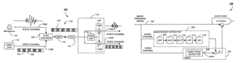
- FIG. 1is a diagram depicting a media distribution system 100 employing one embodiment of the present invention.
- a media program signal 102comprising an audio portion or channel 102 A and a video portion or channel 102 B is provided to a synchronization encoder 108 .
- the video portion 102 B of the media program signal 102includes video segments 104 having picture information such as video frames and non-video segments 106 .
- the non-video segments 106include, for example, the closed captioning information in line 21 of the media program signal, information in the vertical blanking interval (VBI), and/or other information.
- the synchronization encoder 108adds synchronization information in the to the media program signal 102 to generate a sync-encoded media program signal 120 .
- the synchronization information(conceptually illustrated by the asterisks 122 in FIG. 1 ) is added to the non-video segments 106 of the video portion 102 B of the media program signal 102 .
- the synchronization informationcan also be added to the video segments 104 in an unobtrusive manner, for example, by adding the information in the first line of active video in each frame of the video signal 102 B. Because the overwhelming majority of television sets are not aligned with sufficient precision to show the first video line, the synchronization information is virtually invisible to virtually all viewers.
- the sync-encoded media program signal 120is transmitted by transmitter 110 and received by receiver 112 .
- the received sync modified media program signal 120is provided to a synchronization decoder 114 .
- a synchronization detector 115detects the synchronization information in the sync modified media program signal 120 and uses that information to control a variable delay element 118 to synchronize the audio 124 A and video 124 B channels of the media program signal.
- the sync-encoded media program signal 120can be transmitted and received via satellite, cable, the Internet, land line, or other means.
- the media program signal 102may be a live broadcast such as a basketball game.
- the audio portion 102 A and video portions 102 B of the media program 102are provided to the synchronization encoder 108 , and the sync-encoded media program signal 120 provided via satellite or cable to a signal distributor, where additional program material (e.g. advertisements and other information) is added or the media program is edited, and thenceforth transmitted (again, via satellite, cable, or other means) to media program distributors such as satellite or cable distribution systems.
- the media program signal 102is a signal provided by a media program distributor.
- synchronization informationis added to the media program signal as described above to produce the sync-encoded media program signal 120 , and this signal is transmitted to customers having satellite, cable or broadcast television receivers.
- the television receiversdecode the sync-encoded media program signal 120 to recover the synchronization information, and correct for audio/video synchronization errors before presenting the media program to the viewer.
- the audio portion 102 Ais provided by a microphone
- the video portion 102 Bis provided by a video camera 112 .
- the synchronization encoder 108may also accept a composite signal including both the audio portion 102 A and video portion 102 B.
- the synchronization decoderdecodes the audio and video portions 102 A, 102 B of the media program signal 102 before encoding the synchronization information.
- the functionality implemented in the blocks depicted in FIG. 1can be implemented by one or more hardware modules, one or more software modules defining instructions performed by a processor, or a combination of both.
- FIG. 2is a block diagram depicting one embodiment of a synchronization encoder 108 .
- FIG. 2will be discussed with reference to FIGS. 3A and 3B , which present flowcharts describing exemplary process steps that can be used to practice one embodiment of the invention.
- the audio portion of the incoming media program signalis examined to detect an audio event. This is shown in block 302 . This can be performed, for example, by the audio event detector 202 shown in FIG. 2 .
- the audio eventcan be any identifiable pattern in the audio portion 102 A or the media program signal 102 .
- the audio eventcomprises a period of silence followed by an abrupt increase in audio signal intensity. This characteristic is hereinafter termed a “start of sentence” or SoS, but need not be in fact, the start of a sentence.
- the audio eventcomprises a significant increase in the signal intensity of the low frequency portion of the audio spectrum, such as a drum beat.
- the audio eventcomprises a significant increase in the signal intensity of a high-frequency portion of the audio spectrum, such as a cymbal crash.
- the audio eventcan also be determined from more than one measure. For example, two audio sub-events occurring at the same time, such as a musical chord having multiple notes played at the same time.
- the audio eventcan also be determined using speech processing software algorithms which identify words or phrases, particularly those associated with the start of a sentence.
- the audio event detector 202comprises a voice detector which detects the start of a sentence in the audio portion of the signal.
- synchronization informationsuch as a timing interval from the audio event to a datum is measured, as shown in block 304 . This can be performed, for example, by the timer 204 shown in FIG. 2 .
- the datumis the video synchronization pulse in the video portion 102 B of the media program signal 102 .
- the timing intervalis then stored in a third portion of the media program signal, as shown in block 306 .
- the synchronization informationis stored in a portion of the non-video segment 106 of the video portion 102 B of the media program signal 102 .
- the synchronization informationmay be stored in the portion of the media program signal 102 ordinarily dedicated to transmitting closed captioning information (e.g. line 21 ), as described further below.
- the synchronization informationmay also be transmitted in other lines (e.g. line 20 ), or even in part of a video segment 104 .
- the vast majority of televisionsare aligned so that many of the video lines around the edges of the picture are not displayed (this prevents alignment errors from causing black stripes on the periphery of the video image).
- the synchronization informationcan therefore be stored in one of the video lines near the periphery of the image without disturbing the presented video image in the overwhelming majority of television receivers.
- FIG. 3Bis a flow chart illustrating exemplary process steps that can be used to detect the audio event in the audio portion of the media program signal 102 .
- the audio portion of the media program signalmay be a stereo signal with right and left components or a multi-channel coded signal.
- a monaural version of the audio portion of the media program signalmay be generated, as shown in block 308 . While not necessary, this can improve the accuracy of the audio event determination.
- the back channel signalsare mixed to LT and RT, and a monaural channel is created by summing the LT and RT signals.
- the audio component of the media program signalis bandpass-filtered to a range.
- the bandpass filterapproximates that of the vocal bandpass range for human being. This is shown in block 308 and can be performed, for example, by the bandpass filter 208 shown in FIG. 2 . In one embodiment, this is performed by a Gaussian bandpass filter having ⁇ 3 dB points at 500 and 2200 Hz. The selection of this bandpass region passes most of the human voice, but rejects most system noise.
- the audio level of the audio portion of the media program signalis then normalized, as shown in block 312 .
- Thiscan be accomplished, for example, by the automatic gain control (AGC) module 210 shown in FIG. 2 .
- the attack and decay time of the AGCcan be varied to optimize performance.
- the signalis then rectified and low pass filtered, as shown in blocks 314 and 316 , respectively. These operations can be performed by the rectifier 212 and low pass filter (LPF) 214 shown in FIG. 2 .
- the resulting pre-processed signalis applied to a silence interval detector (SID) 216 which determines a silence interval t s , during which the pre-processed audio signal has an amplitude below the AGC threshold and identifies the end of the silence interval as the start of sentence time if the silence interval ts exceeds a silence interval threshold t s thresh .
- SIDsilence interval detector
- FIG. 4is a diagram illustrating one example of how a start of sentence (SoS) period can be defined.
- SoS periodis defined as a period of silence followed by a syllable (or abrupt increase in audio level).
- the start of the sentence periodis defined according to the set of rules. These rules make use of characterizations of the processed signal as being (1) silent, or a (2) syllable.
- the processed signalcan be characterized as “silent” when the amplitude of the processed signal is below a silence threshold T silence .
- the silence threshold T silenceis 26 dB below the AGC threshold.
- the processed signalcan be characterized as a syllable when the processed signal magnitude is above a syllable threshold T syllable .
- a silence interval ⁇ t silence 404 of the processed signalis a time interval when the processed signal remains silent for a minimum time period min ⁇ t silence .
- the signalis deemed to be silent when the processed signal remains at least 20 dB below the AGC threshold for at least 20 milliseconds.
- Time interval 404represents an exemplary silent period.
- a SoSis identified when the processed signal is at or below the silence threshold T silence for a minimum time period ⁇ t silence 404 , followed by an increase in the amplitude of the processed signal to at least the syllable threshold T syllable within a syllable rise time ⁇ t syllable 406 .
- a valid SoSmust have no false SoS designations in the within a period ⁇ t false 402 of the onset of the silence period ⁇ t silence .
- a false SoS designationis one in which there is ⁇ t silence of silence followed by a syllable, but the processed signal does not violate other timing constraints.
- An examples of one such timing constraintis a constraint which requires that there are no similarly identified events within a preceding time period (e.g. no SoS designations within a preceding period).
- representative values for ⁇ t false 402 , ⁇ t silence 404 , ⁇ t syllable 406 , and ⁇ t SoS 408are >250 milliseconds, >20 milliseconds, ⁇ 2 milliseconds, and >250 milliseconds, respectively.
- a timing interval ⁇ t SoS-sync 414 from the SoS timing reference 410 to the vertical sync pulse t V sync 412is determined.
- Vertical sync pulsesare described in “Digital Television Fundamentals, by Michael Robin and Michel Poulin, 1998, which is hereby incorporated by reference herein.
- the reference timing valueis determined by rounding to an integer number of milliseconds.
- a valid range for the timing interval ⁇ t SoS-sync 414is approximately zero to 17 milliseconds for 30 frame systems, and zero to 20 milliseconds for 25 frame systems. It is noted that the foregoing describes only one embodiment of the present invention. Given the teaching above, it is possible to define an operational system using different values for the parameters above. It should also be noted that the steps of generating a monaural signal, bandpass filtering to a vocal bandpass range, normalizing the signal with AGC, rectifying and further low pass filtering the signal are operations which improve the accuracy of the determination of the SoS, but may not be required to practice the present invention in some embodiments.
- the start of the sentencecan be determined by digital algorithmic techniques that do not involve low pass filtering.
- the combination of the multi-channel audio signal to a single monaural signalsimplifies the design and operation of the system, the information on such multiple channels may instead be used to improve the start of sentence determination.
- this third portionis the captioning portion of the media program signal.
- line 21 of the vertical blanking intervalis allocated to carry two bytes of closed captioning information.
- Closed captioning informationcan be included on line 21 of the first field of each video frame and/or on line 21 of the second field of the video frame.
- the first field of the video frameincludes CC1, CC2, Text 1 and Text 2 channels and the second field includes CC3, CC4, Text 3 and Text 4, and XDS channels.
- a plurality of special non-printing characterscan be used to represent the timing values. For example, a timing interval ⁇ t SoS-sync of 0 msec can be represented by a first non-printing character, a timing interval ⁇ t SoS-sync of 10 msec can be represented by a second non-printing character, and so on.
- the maximum rate at which the timing interval values ⁇ t SoS-sync 414 can be storedis approximately one every 500 milliseconds. It is preferable to retain any existing closed-captioning information in the signal.
- the timing interval value ⁇ t SoS-sync 414is transmitted in the form of two special characters. If there is CC1, CC3, Text 1 or Text 2 data already present on line 21 , the timing interval value ⁇ t SoS-sync 414 can be discarded, and the CC1 or CC3 data already present on line 21 is left undisturbed.
- line 21 of frame 2already includes closed captioning information (CC2, CC4, Text 3, Text 4, XDS data)
- this datamay be delayed until the next frame, and the timing interval value ⁇ t SoS-sync 414 inserted in its place.
- the closed captioning informationmay be simply overwritten.
- the synchronization informationis written using printing characters, but is written to closed captioning portions that are not ordinarily viewed by the user.
- any characterscan be used to store the synchronization information in the CC2, CC3, CC4, Text 1 or Text 2 channels, even by simply writing the synchronization information values directly.
- this informationwould be displayed in a closed captioning window, and may appear as random characters or numbers.
- the original closed captioning informationis still available and viewable, so long as the user commands the television receiver to display CC1 closed-captioning information.
- the estimate of when the SoS occurscan be improved by statistical analysis of the audio and/or video waveforms. Such techniques reduce the probability of errors in the SoS determination caused by imperfect audio measuring equipment and audio distortion. Such statistical analysis can be accomplished by generating a histogram of the results. Correct SoS data points are likely to be closely clustered together, while erroneous results are likely to be widely scattered. Using such analysis, such widely scattered timing references can be disregarded.
- the present inventioncan also be practiced with current and evolving digital television standards such as EIA-708.
- EIA-708offers an enhanced character set with more accented letters and non-English letters, and more special symbols, and higher bandwidth, as well as other improvements.
- the closed captioningmay be available in earlier embodiments of MPEG encoding of NTSC signals using captioning encoders, and that current and planned MPEG encoding make specific allowances to transmit closed captioning information.
- the present inventionmay be practiced by storing the timing reference information in the closed captioning portions of the media program signal supported by these formats.
- Lipsync timing errorstend to be fixed or to move very slowly. By accumulating data over a period of time and discarding erroneous samples, the timing error can be determined and the synchronization between the video and the audio portions of the media program can be re-established and maintained.
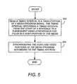
- FIG. 5is a flow chart illustrating exemplary method steps that can be used to decode and use the synchronization information.
- Synchronization informationsuch as a timing interval disposed in a third portion of a media program signal is read, as shown in block 502 .
- the audio and video portions of the media programcan then be synchronized using the timing interval, as shown in block 504 .
- the foregoing stepsare performed by the synchronizing detector 116 and the synchronizer 118 of the synchronizing decoder 114 shown in FIG. 1 .
- the sync-encoded media program signal 120is provided to the synchronizing detector 116 , which reads and processes the timing interval in a third portion of the media program signal.
- a communicatively coupled synchronizer 118accepts the timing interval uses the timing interval to synchronize the audio and video portions of the media program.
- this synchronizationis performed by delaying or advancing the audio portion of the media program relative to the video portion of the media program using audio delay element 118 A.
- the video portion of the media programcan be delayed or advanced using video delay element 118 B, while leaving the audio portion timing untouched, if desired. Further, both the audio and video portions of the media program can be adjusted, if desired.
- the synchronizing detector 116processes the timing interval in the third portion of the media program signal by generating a second timing reference, using techniques analogous to those outlined above.
- a valid value for the second timing referenceis between ⁇ 200 milliseconds and +217 milliseconds for 30 frame systems, and between ⁇ 200 and +220 milliseconds for 25 frame systems.
- the second timing referenceis compared to the timing reference ⁇ t SoS-sync 474 read from the third portion of the media program signal.
- the difference between the first and second timing referencesrepresents a lipsync error. Typically, the lipsync error is within ⁇ 200 milliseconds.
- the synchronizer 552adjusts the timing of the video or audio portions of the media program signal (or both) to account for this lipsync error.
Landscapes
- Engineering & Computer Science (AREA)
- Multimedia (AREA)
- Signal Processing (AREA)
- Computer Security & Cryptography (AREA)
- Television Receiver Circuits (AREA)
- Two-Way Televisions, Distribution Of Moving Picture Or The Like (AREA)
- Television Systems (AREA)
Abstract
Description
Claims (26)
Priority Applications (1)
| Application Number | Priority Date | Filing Date | Title |
|---|---|---|---|
| US11/784,758US7948559B2 (en) | 2002-09-09 | 2007-04-07 | Method and apparatus for lipsync measurement and correction |
Applications Claiming Priority (3)
| Application Number | Priority Date | Filing Date | Title |
|---|---|---|---|
| US40934602P | 2002-09-09 | 2002-09-09 | |
| US10/654,836US7212248B2 (en) | 2002-09-09 | 2003-09-04 | Method and apparatus for lipsync measurement and correction |
| US11/784,758US7948559B2 (en) | 2002-09-09 | 2007-04-07 | Method and apparatus for lipsync measurement and correction |
Related Parent Applications (1)
| Application Number | Title | Priority Date | Filing Date |
|---|---|---|---|
| US10/654,836ContinuationUS7212248B2 (en) | 2002-09-09 | 2003-09-04 | Method and apparatus for lipsync measurement and correction |
Publications (2)
| Publication Number | Publication Date |
|---|---|
| US20070201708A1 US20070201708A1 (en) | 2007-08-30 |
| US7948559B2true US7948559B2 (en) | 2011-05-24 |
Family
ID=32329011
Family Applications (2)
| Application Number | Title | Priority Date | Filing Date |
|---|---|---|---|
| US10/654,836Expired - Fee RelatedUS7212248B2 (en) | 2002-09-09 | 2003-09-04 | Method and apparatus for lipsync measurement and correction |
| US11/784,758Active2026-01-28US7948559B2 (en) | 2002-09-09 | 2007-04-07 | Method and apparatus for lipsync measurement and correction |
Family Applications Before (1)
| Application Number | Title | Priority Date | Filing Date |
|---|---|---|---|
| US10/654,836Expired - Fee RelatedUS7212248B2 (en) | 2002-09-09 | 2003-09-04 | Method and apparatus for lipsync measurement and correction |
Country Status (1)
| Country | Link |
|---|---|
| US (2) | US7212248B2 (en) |
Families Citing this family (27)
| Publication number | Priority date | Publication date | Assignee | Title |
|---|---|---|---|---|
| US9432555B2 (en)* | 2003-05-16 | 2016-08-30 | J. Carl Cooper | System and method for AV sync correction by remote sensing |
| US8133115B2 (en) | 2003-10-22 | 2012-03-13 | Sony Computer Entertainment America Llc | System and method for recording and displaying a graphical path in a video game |
| US20070223874A1 (en)* | 2004-04-07 | 2007-09-27 | Koninklijke Philips Electronics, N.V. | Video-Audio Synchronization |
| US7333150B2 (en)* | 2004-05-14 | 2008-02-19 | Pixel Instruments Corporation | Method, system, and program product for eliminating error contribution from production switchers with internal DVEs |
| JP4517727B2 (en)* | 2004-05-27 | 2010-08-04 | ヤマハ株式会社 | Audio / Video Amplifier |
| WO2006101504A1 (en)* | 2004-06-22 | 2006-09-28 | Sarnoff Corporation | Method and apparatus for measuring and/or correcting audio/visual synchronization |
| US20060071933A1 (en) | 2004-10-06 | 2006-04-06 | Sony Computer Entertainment Inc. | Application binary interface for multi-pass shaders |
| US7636126B2 (en) | 2005-06-22 | 2009-12-22 | Sony Computer Entertainment Inc. | Delay matching in audio/video systems |
| US7764713B2 (en)* | 2005-09-28 | 2010-07-27 | Avaya Inc. | Synchronization watermarking in multimedia streams |
| JP2007124090A (en)* | 2005-10-26 | 2007-05-17 | Renesas Technology Corp | Information apparatus |
| US7880746B2 (en) | 2006-05-04 | 2011-02-01 | Sony Computer Entertainment Inc. | Bandwidth management through lighting control of a user environment via a display device |
| US7965859B2 (en) | 2006-05-04 | 2011-06-21 | Sony Computer Entertainment Inc. | Lighting control of a user environment via a display device |
| US8363161B2 (en)* | 2006-05-26 | 2013-01-29 | Broadcom Corporation | Systems, methods, and apparatus for synchronization of audio and video signals |
| US7693190B2 (en)* | 2006-11-22 | 2010-04-06 | Cisco Technology, Inc. | Lip synchronization for audio/video transmissions over a network |
| JP2011504034A (en)* | 2007-11-14 | 2011-01-27 | コーニンクレッカ フィリップス エレクトロニクス エヌ ヴィ | How to determine the starting point of a semantic unit in an audiovisual signal |
| WO2009076723A1 (en)* | 2007-12-19 | 2009-06-25 | Colin Simon | Device and method for synchronisation of digital video and audio streams to media presentation devices |
| US8254355B2 (en) | 2008-09-17 | 2012-08-28 | Airhop Communications, Inc. | Method and apparatus for utilizing a second receiver to establish time and frequency |
| WO2010068151A1 (en)* | 2008-12-08 | 2010-06-17 | Telefonaktiebolaget L M Ericsson (Publ) | Device and method for synchronizing received audio data with video data |
| US8656432B2 (en)* | 2009-05-12 | 2014-02-18 | At&T Intellectual Property I, L.P. | Providing audio signals using a network back-channel |
| US8436939B2 (en)* | 2009-10-25 | 2013-05-07 | Tektronix, Inc. | AV delay measurement and correction via signature curves |
| WO2011071928A2 (en)* | 2009-12-07 | 2011-06-16 | Pixel Instruments Corporation | Dialogue detector and correction |
| US10786736B2 (en) | 2010-05-11 | 2020-09-29 | Sony Interactive Entertainment LLC | Placement of user information in a game space |
| US9342817B2 (en) | 2011-07-07 | 2016-05-17 | Sony Interactive Entertainment LLC | Auto-creating groups for sharing photos |
| US9972357B2 (en) | 2014-01-08 | 2018-05-15 | Adobe Systems Incorporated | Audio and video synchronizing perceptual model |
| US10311862B2 (en) | 2015-12-23 | 2019-06-04 | Rovi Guides, Inc. | Systems and methods for conversations with devices about media using interruptions and changes of subjects |
| TW201931863A (en)* | 2018-01-12 | 2019-08-01 | 圓剛科技股份有限公司 | Multimedia signal synchronization apparatus and synchronization method thereof |
| US11871068B1 (en)* | 2019-12-12 | 2024-01-09 | Amazon Technologies, Inc. | Techniques for detecting non-synchronization between audio and video |
Citations (45)
| Publication number | Priority date | Publication date | Assignee | Title |
|---|---|---|---|---|
| US4099202A (en) | 1977-05-02 | 1978-07-04 | Robot Research, Inc. | Multiplexed communication of voice signals and slow scan television signals over a common communication channel |
| US4218705A (en) | 1977-09-05 | 1980-08-19 | Nippon Electric Company, Ltd. | Delay compensator for a television signal |
| US4313135A (en) | 1980-07-28 | 1982-01-26 | Cooper J Carl | Method and apparatus for preserving or restoring audio to video synchronization |
| US4618890A (en) | 1985-01-22 | 1986-10-21 | Nec Corporation | Digital audio synchronizing system with mute time switching function |
| US4703355A (en) | 1985-09-16 | 1987-10-27 | Cooper J Carl | Audio to video timing equalizer method and apparatus |
| US4743981A (en) | 1986-01-31 | 1988-05-10 | Walt Disney Productions | System for synchronizing audiotape and videotape machines |
| US4851909A (en) | 1987-09-24 | 1989-07-25 | Robert Bosch Gmbh | Method and apparatus for maintaining audio/ video synchronism in a television signal read-out from a digital buffer memory by a reference signal |
| US4963967A (en) | 1989-03-10 | 1990-10-16 | Tektronix, Inc. | Timing audio and video signals with coincidental markers |
| US4969041A (en) | 1988-09-23 | 1990-11-06 | Dubner Computer Systems, Inc. | Embedment of data in a video signal |
| USRE33535E (en) | 1985-09-16 | 1991-02-12 | Audio to video timing equalizer method and apparatus | |
| US5091947A (en) | 1987-06-04 | 1992-02-25 | Ricoh Company, Ltd. | Speech recognition method and apparatus |
| US5243424A (en) | 1990-05-16 | 1993-09-07 | Thames Television Plc | Apparatus and method for the measurement of tuning delay between a video signal and an audio signal |
| US5365579A (en) | 1991-12-27 | 1994-11-15 | Lucasarts Entertainment Company | Method and apparatus for remote control and synchronization allowing for simultaneous remote collaboration |
| US5572261A (en) | 1995-06-07 | 1996-11-05 | Cooper; J. Carl | Automatic audio to video timing measurement device and method |
| US5642171A (en) | 1994-06-08 | 1997-06-24 | Dell Usa, L.P. | Method and apparatus for synchronizing audio and video data streams in a multimedia system |
| US5751368A (en) | 1994-10-11 | 1998-05-12 | Pixel Instruments Corp. | Delay detector apparatus and method for multiple video sources |
| US5818520A (en) | 1996-02-12 | 1998-10-06 | Tektronix, Inc. | Programmable instrument for automatic measurement of compressed video quality |
| US5880788A (en) | 1996-03-25 | 1999-03-09 | Interval Research Corporation | Automated synchronization of video image sequences to new soundtracks |
| US6097558A (en) | 1994-03-31 | 2000-08-01 | Sony Corporation | Digital audio signal transmission apparatus with data blocks of varying sizes |
| US6233389B1 (en) | 1998-07-30 | 2001-05-15 | Tivo, Inc. | Multimedia time warping system |
| US6246439B1 (en) | 1997-03-28 | 2001-06-12 | Tektronix, Inc. | Transparent embedment of data in a video signal |
| US6269122B1 (en) | 1998-01-02 | 2001-07-31 | Intel Corporation | Synchronization of related audio and video streams |
| US6330033B1 (en) | 1995-12-07 | 2001-12-11 | James Carl Cooper | Pulse detector for ascertaining the processing delay of a signal |
| US6373960B1 (en) | 1998-01-06 | 2002-04-16 | Pixel Tools Corporation | Embedding watermarks into compressed video data |
| US6407769B1 (en) | 1998-02-12 | 2002-06-18 | John Robert Emmett | Measurement of timing delay between associated signals or bitstreams |
| US6414960B1 (en) | 1998-12-29 | 2002-07-02 | International Business Machines Corp. | Apparatus and method of in-service audio/video synchronization testing |
| US20020140859A1 (en) | 2001-03-27 | 2002-10-03 | Takaki Kariatsumari | Digital broadcast receiving apparatus and control method thereof |
| US20020140857A1 (en) | 2001-03-30 | 2002-10-03 | Limaye Ajit M. | Audio/video processing engine |
| US6480902B1 (en) | 1999-05-25 | 2002-11-12 | Institute For Information Industry | Intermedia synchronization system for communicating multimedia data in a computer network |
| US20030122964A1 (en) | 2002-01-02 | 2003-07-03 | Sony Electronics Inc. | Synchronization network, system and method for synchronizing audio |
| US20030142232A1 (en) | 2002-01-31 | 2003-07-31 | Albean David Lawrence | Audio/video system providing variable delay |
| US6697120B1 (en) | 1999-06-24 | 2004-02-24 | Koninklijke Philips Electronics N.V. | Post-synchronizing an information stream including the replacement of lip objects |
| US6757300B1 (en) | 1998-06-04 | 2004-06-29 | Innes Corporation Pty Ltd | Traffic verification system |
| US20040179043A1 (en) | 2001-04-13 | 2004-09-16 | Serge Viellescaze | Method and system for animating a figure in three dimensions |
| US20040227856A1 (en) | 2003-05-16 | 2004-11-18 | Cooper J. Carl | Method and apparatus for determining relative timing of image and associated information |
| US6836295B1 (en) | 1995-12-07 | 2004-12-28 | J. Carl Cooper | Audio to video timing measurement for MPEG type television systems |
| US6906755B2 (en) | 2002-01-04 | 2005-06-14 | Microsoft Corporation | Method and apparatus for synchronizing audio and video data |
| US6912010B2 (en) | 2002-04-15 | 2005-06-28 | Tektronix, Inc. | Automated lip sync error correction |
| US6961512B1 (en) | 1999-12-27 | 2005-11-01 | Dvd Tech Co., Ltd. | Subtitle management method for digital video disk |
| US20060007356A1 (en) | 2002-10-24 | 2006-01-12 | Thomson Licensing S.A. | Method and system for maintaining lip synchronization |
| US7020894B1 (en) | 1998-07-24 | 2006-03-28 | Leeds Technologies Limited | Video and audio synchronization |
| US7030930B2 (en)* | 2001-03-06 | 2006-04-18 | Ati Technologies, Inc. | System for digitized audio stream synchronization and method thereof |
| US7043749B1 (en) | 1998-02-27 | 2006-05-09 | Tandberg Telecom As | Audio-video packet synchronization at network gateway |
| US7593061B2 (en) | 2004-06-22 | 2009-09-22 | Sarnoff Corporation | Method and apparatus for measuring and/or correcting audio/visual synchronization |
| US7692724B2 (en) | 2004-10-12 | 2010-04-06 | Samsung Electronics Co., Ltd. | Method and apparatus to synchronize audio and video |
- 2003
- 2003-09-04USUS10/654,836patent/US7212248B2/ennot_activeExpired - Fee Related
- 2007
- 2007-04-07USUS11/784,758patent/US7948559B2/enactiveActive
Patent Citations (47)
| Publication number | Priority date | Publication date | Assignee | Title |
|---|---|---|---|---|
| US4099202A (en) | 1977-05-02 | 1978-07-04 | Robot Research, Inc. | Multiplexed communication of voice signals and slow scan television signals over a common communication channel |
| US4218705A (en) | 1977-09-05 | 1980-08-19 | Nippon Electric Company, Ltd. | Delay compensator for a television signal |
| US4313135A (en) | 1980-07-28 | 1982-01-26 | Cooper J Carl | Method and apparatus for preserving or restoring audio to video synchronization |
| US4313135B1 (en) | 1980-07-28 | 1996-01-02 | J Carl Cooper | Method and apparatus for preserving or restoring audio to video |
| US4618890A (en) | 1985-01-22 | 1986-10-21 | Nec Corporation | Digital audio synchronizing system with mute time switching function |
| USRE33535E (en) | 1985-09-16 | 1991-02-12 | Audio to video timing equalizer method and apparatus | |
| US4703355A (en) | 1985-09-16 | 1987-10-27 | Cooper J Carl | Audio to video timing equalizer method and apparatus |
| US4743981A (en) | 1986-01-31 | 1988-05-10 | Walt Disney Productions | System for synchronizing audiotape and videotape machines |
| US5091947A (en) | 1987-06-04 | 1992-02-25 | Ricoh Company, Ltd. | Speech recognition method and apparatus |
| US4851909A (en) | 1987-09-24 | 1989-07-25 | Robert Bosch Gmbh | Method and apparatus for maintaining audio/ video synchronism in a television signal read-out from a digital buffer memory by a reference signal |
| US4969041A (en) | 1988-09-23 | 1990-11-06 | Dubner Computer Systems, Inc. | Embedment of data in a video signal |
| US4963967A (en) | 1989-03-10 | 1990-10-16 | Tektronix, Inc. | Timing audio and video signals with coincidental markers |
| US5243424A (en) | 1990-05-16 | 1993-09-07 | Thames Television Plc | Apparatus and method for the measurement of tuning delay between a video signal and an audio signal |
| US5365579A (en) | 1991-12-27 | 1994-11-15 | Lucasarts Entertainment Company | Method and apparatus for remote control and synchronization allowing for simultaneous remote collaboration |
| US6097558A (en) | 1994-03-31 | 2000-08-01 | Sony Corporation | Digital audio signal transmission apparatus with data blocks of varying sizes |
| US5642171A (en) | 1994-06-08 | 1997-06-24 | Dell Usa, L.P. | Method and apparatus for synchronizing audio and video data streams in a multimedia system |
| US5751368A (en) | 1994-10-11 | 1998-05-12 | Pixel Instruments Corp. | Delay detector apparatus and method for multiple video sources |
| US5572261A (en) | 1995-06-07 | 1996-11-05 | Cooper; J. Carl | Automatic audio to video timing measurement device and method |
| US6836295B1 (en) | 1995-12-07 | 2004-12-28 | J. Carl Cooper | Audio to video timing measurement for MPEG type television systems |
| US6330033B1 (en) | 1995-12-07 | 2001-12-11 | James Carl Cooper | Pulse detector for ascertaining the processing delay of a signal |
| US5818520A (en) | 1996-02-12 | 1998-10-06 | Tektronix, Inc. | Programmable instrument for automatic measurement of compressed video quality |
| US5880788A (en) | 1996-03-25 | 1999-03-09 | Interval Research Corporation | Automated synchronization of video image sequences to new soundtracks |
| US6246439B1 (en) | 1997-03-28 | 2001-06-12 | Tektronix, Inc. | Transparent embedment of data in a video signal |
| US6269122B1 (en) | 1998-01-02 | 2001-07-31 | Intel Corporation | Synchronization of related audio and video streams |
| US6373960B1 (en) | 1998-01-06 | 2002-04-16 | Pixel Tools Corporation | Embedding watermarks into compressed video data |
| US6407769B1 (en) | 1998-02-12 | 2002-06-18 | John Robert Emmett | Measurement of timing delay between associated signals or bitstreams |
| US7043749B1 (en) | 1998-02-27 | 2006-05-09 | Tandberg Telecom As | Audio-video packet synchronization at network gateway |
| US6757300B1 (en) | 1998-06-04 | 2004-06-29 | Innes Corporation Pty Ltd | Traffic verification system |
| US7020894B1 (en) | 1998-07-24 | 2006-03-28 | Leeds Technologies Limited | Video and audio synchronization |
| US6233389B1 (en) | 1998-07-30 | 2001-05-15 | Tivo, Inc. | Multimedia time warping system |
| US6414960B1 (en) | 1998-12-29 | 2002-07-02 | International Business Machines Corp. | Apparatus and method of in-service audio/video synchronization testing |
| US6480902B1 (en) | 1999-05-25 | 2002-11-12 | Institute For Information Industry | Intermedia synchronization system for communicating multimedia data in a computer network |
| US6697120B1 (en) | 1999-06-24 | 2004-02-24 | Koninklijke Philips Electronics N.V. | Post-synchronizing an information stream including the replacement of lip objects |
| US6961512B1 (en) | 1999-12-27 | 2005-11-01 | Dvd Tech Co., Ltd. | Subtitle management method for digital video disk |
| US7030930B2 (en)* | 2001-03-06 | 2006-04-18 | Ati Technologies, Inc. | System for digitized audio stream synchronization and method thereof |
| US20020140859A1 (en) | 2001-03-27 | 2002-10-03 | Takaki Kariatsumari | Digital broadcast receiving apparatus and control method thereof |
| US20020140857A1 (en) | 2001-03-30 | 2002-10-03 | Limaye Ajit M. | Audio/video processing engine |
| US20040179043A1 (en) | 2001-04-13 | 2004-09-16 | Serge Viellescaze | Method and system for animating a figure in three dimensions |
| US20030122964A1 (en) | 2002-01-02 | 2003-07-03 | Sony Electronics Inc. | Synchronization network, system and method for synchronizing audio |
| US20050238059A1 (en)* | 2002-01-04 | 2005-10-27 | Microsoft Corporation | Method and apparatus for synchronizing audio and video data |
| US6906755B2 (en) | 2002-01-04 | 2005-06-14 | Microsoft Corporation | Method and apparatus for synchronizing audio and video data |
| US20030142232A1 (en) | 2002-01-31 | 2003-07-31 | Albean David Lawrence | Audio/video system providing variable delay |
| US6912010B2 (en) | 2002-04-15 | 2005-06-28 | Tektronix, Inc. | Automated lip sync error correction |
| US20060007356A1 (en) | 2002-10-24 | 2006-01-12 | Thomson Licensing S.A. | Method and system for maintaining lip synchronization |
| US20040227856A1 (en) | 2003-05-16 | 2004-11-18 | Cooper J. Carl | Method and apparatus for determining relative timing of image and associated information |
| US7593061B2 (en) | 2004-06-22 | 2009-09-22 | Sarnoff Corporation | Method and apparatus for measuring and/or correcting audio/visual synchronization |
| US7692724B2 (en) | 2004-10-12 | 2010-04-06 | Samsung Electronics Co., Ltd. | Method and apparatus to synchronize audio and video |
Non-Patent Citations (3)
| Title |
|---|
| Non-final Office action dated Jul. 15, 2010 in U.S. Appl. No. 11/529,941, filed Sep. 29, 2006 by Leon J. Stanger et al. |
| Notice of Allowance dated Jan. 18, 2011 in U.S. Appl. No. 11/529,941, filed Sep. 29, 2006 by Leon J. Stanger et al. |
| Robin, Michael et al.; "Digital Television Fundamentals-Design and Installation of Video and Audio Systems"; McGraw-Hill; Chapter 8, title pages and pp. 345-425. |
Also Published As
| Publication number | Publication date |
|---|---|
| US20070201708A1 (en) | 2007-08-30 |
| US7212248B2 (en) | 2007-05-01 |
| US20040100582A1 (en) | 2004-05-27 |
Similar Documents
| Publication | Publication Date | Title |
|---|---|---|
| US7948559B2 (en) | Method and apparatus for lipsync measurement and correction | |
| US9692945B2 (en) | AV timing measurement and correction for digital television | |
| US7948558B2 (en) | Audio video timing measurement and synchronization | |
| US8363161B2 (en) | Systems, methods, and apparatus for synchronization of audio and video signals | |
| US4605964A (en) | Method and apparatus for editing the output of a television set | |
| US6690813B2 (en) | Method and apparatus for recording and reproducing electronic watermark information, and recording medium | |
| KR101741747B1 (en) | Apparatus and method for processing real time advertisement insertion on broadcast | |
| JP4448477B2 (en) | Delay control apparatus and delay control program for video signal with caption | |
| US8035741B2 (en) | Apparatus and method for detecting vertical blanking interval signals | |
| US5223930A (en) | Data recovery system using dot clock counting | |
| EP0472572B1 (en) | Data transmission in the active picture period | |
| HK1004053B (en) | Data transmission in the active picture period | |
| US6130718A (en) | Method and device for correcting errors in the opening of time windows for recovering data with horizontal synchronization pulses | |
| US7236686B2 (en) | Method and apparatus for transmitting a signal, method and apparatus for receiving a signal, VBI signal generating apparatus, video signal transmitting apparatus, video signal processing apparatus, video signal receiving apparatus, decoding apparatus, and recording medium for recording a video signal | |
| KR100299772B1 (en) | Method of adaptive control of the presence of a copy protection signal | |
| CN1176557A (en) | Subtitle signal playback method for viewer-selective subtitle playback | |
| JPH0888840A (en) | Teletext system discrimination device | |
| JPH02224487A (en) | Data signal sending device | |
| JP2009055280A (en) | Video signal processing unit | |
| JPS6130185A (en) | Chost removing device for character broadcasting |
Legal Events
| Date | Code | Title | Description |
|---|---|---|---|
| AS | Assignment | Owner name:THE DIRECTV GROUP, INC., CALIFORNIA Free format text:CHANGE OF NAME;ASSIGNOR:HUGHES ELECTRONICS CORPORATION;REEL/FRAME:025037/0783 Effective date:20040316 | |
| STCF | Information on status: patent grant | Free format text:PATENTED CASE | |
| FPAY | Fee payment | Year of fee payment:4 | |
| MAFP | Maintenance fee payment | Free format text:PAYMENT OF MAINTENANCE FEE, 8TH YEAR, LARGE ENTITY (ORIGINAL EVENT CODE: M1552); ENTITY STATUS OF PATENT OWNER: LARGE ENTITY Year of fee payment:8 | |
| AS | Assignment | Owner name:DIRECTV, LLC, CALIFORNIA Free format text:ASSIGNMENT OF ASSIGNORS INTEREST;ASSIGNOR:THE DIRECTV GROUP, INC.;REEL/FRAME:057033/0451 Effective date:20210728 | |
| AS | Assignment | Owner name:CREDIT SUISSE AG, CAYMAN ISLANDS BRANCH, AS COLLATERAL AGENT, NEW YORK Free format text:SECURITY AGREEMENT;ASSIGNOR:DIRECTV, LLC;REEL/FRAME:057695/0084 Effective date:20210802 | |
| AS | Assignment | Owner name:THE BANK OF NEW YORK MELLON TRUST COMPANY, N.A. AS COLLATERAL AGENT, TEXAS Free format text:SECURITY AGREEMENT;ASSIGNOR:DIRECTV, LLC;REEL/FRAME:058220/0531 Effective date:20210802 | |
| MAFP | Maintenance fee payment | Free format text:PAYMENT OF MAINTENANCE FEE, 12TH YEAR, LARGE ENTITY (ORIGINAL EVENT CODE: M1553); ENTITY STATUS OF PATENT OWNER: LARGE ENTITY Year of fee payment:12 | |
| AS | Assignment | Owner name:THE BANK OF NEW YORK MELLON TRUST COMPANY, N.A., AS COLLATERAL AGENT, TEXAS Free format text:SECURITY AGREEMENT;ASSIGNOR:DIRECTV, LLC;REEL/FRAME:066371/0690 Effective date:20240124 |