US7948558B2 - Audio video timing measurement and synchronization - Google Patents
Audio video timing measurement and synchronizationDownload PDFInfo
- Publication number
- US7948558B2 US7948558B2US11/529,941US52994106AUS7948558B2US 7948558 B2US7948558 B2US 7948558B2US 52994106 AUS52994106 AUS 52994106AUS 7948558 B2US7948558 B2US 7948558B2
- Authority
- US
- United States
- Prior art keywords
- video
- signal
- timing signal
- audio signal
- timing
- Prior art date
- Legal status (The legal status is an assumption and is not a legal conclusion. Google has not performed a legal analysis and makes no representation as to the accuracy of the status listed.)
- Active, expires
Links
- 238000005259measurementMethods0.000titledescription12
- 230000005236sound signalEffects0.000claimsabstractdescription96
- 238000000034methodMethods0.000claimsabstractdescription56
- 238000004458analytical methodMethods0.000claimsabstractdescription12
- 230000008859changeEffects0.000claimsdescription22
- 230000002123temporal effectEffects0.000claimsdescription9
- 230000001934delayEffects0.000claimsdescription8
- 238000010586diagramMethods0.000description13
- 238000012545processingMethods0.000description13
- 230000003190augmentative effectEffects0.000description9
- 238000009826distributionMethods0.000description9
- 238000012360testing methodMethods0.000description5
- 238000004519manufacturing processMethods0.000description4
- 230000003595spectral effectEffects0.000description4
- 238000001514detection methodMethods0.000description3
- 230000008569processEffects0.000description3
- 230000005540biological transmissionEffects0.000description2
- 230000006835compressionEffects0.000description2
- 238000007906compressionMethods0.000description2
- 238000012937correctionMethods0.000description2
- 230000003111delayed effectEffects0.000description2
- 238000003860storageMethods0.000description2
- 230000001960triggered effectEffects0.000description2
- 238000012935AveragingMethods0.000description1
- 238000013459approachMethods0.000description1
- 230000009286beneficial effectEffects0.000description1
- 230000008901benefitEffects0.000description1
- 239000003990capacitorSubstances0.000description1
- 230000015556catabolic processEffects0.000description1
- 238000006243chemical reactionMethods0.000description1
- 230000000295complement effectEffects0.000description1
- 239000002131composite materialSubstances0.000description1
- 230000003247decreasing effectEffects0.000description1
- 238000006731degradation reactionMethods0.000description1
- 230000000694effectsEffects0.000description1
- 238000005516engineering processMethods0.000description1
- 238000003780insertionMethods0.000description1
- 230000037431insertionEffects0.000description1
- 238000009434installationMethods0.000description1
- 239000000203mixtureSubstances0.000description1
- 238000012986modificationMethods0.000description1
- 230000004048modificationEffects0.000description1
- 235000012736patent blue VNutrition0.000description1
- 230000002085persistent effectEffects0.000description1
- 238000009877renderingMethods0.000description1
- 230000004044responseEffects0.000description1
- 238000007619statistical methodMethods0.000description1
- 230000001360synchronised effectEffects0.000description1
- 230000007704transitionEffects0.000description1
- 239000002699waste materialSubstances0.000description1
Images


Classifications
- H—ELECTRICITY
- H04—ELECTRIC COMMUNICATION TECHNIQUE
- H04N—PICTORIAL COMMUNICATION, e.g. TELEVISION
- H04N5/00—Details of television systems
- H04N5/04—Synchronising
- H04N5/06—Generation of synchronising signals
- H04N5/067—Arrangements or circuits at the transmitter end
- H—ELECTRICITY
- H04—ELECTRIC COMMUNICATION TECHNIQUE
- H04N—PICTORIAL COMMUNICATION, e.g. TELEVISION
- H04N21/00—Selective content distribution, e.g. interactive television or video on demand [VOD]
- H04N21/20—Servers specifically adapted for the distribution of content, e.g. VOD servers; Operations thereof
- H04N21/23—Processing of content or additional data; Elementary server operations; Server middleware
- H04N21/236—Assembling of a multiplex stream, e.g. transport stream, by combining a video stream with other content or additional data, e.g. inserting a URL [Uniform Resource Locator] into a video stream, multiplexing software data into a video stream; Remultiplexing of multiplex streams; Insertion of stuffing bits into the multiplex stream, e.g. to obtain a constant bit-rate; Assembling of a packetised elementary stream
- H04N21/2368—Multiplexing of audio and video streams
- H—ELECTRICITY
- H04—ELECTRIC COMMUNICATION TECHNIQUE
- H04N—PICTORIAL COMMUNICATION, e.g. TELEVISION
- H04N21/00—Selective content distribution, e.g. interactive television or video on demand [VOD]
- H04N21/40—Client devices specifically adapted for the reception of or interaction with content, e.g. set-top-box [STB]; Operations thereof
- H04N21/43—Processing of content or additional data, e.g. demultiplexing additional data from a digital video stream; Elementary client operations, e.g. monitoring of home network or synchronising decoder's clock; Client middleware
- H04N21/434—Disassembling of a multiplex stream, e.g. demultiplexing audio and video streams, extraction of additional data from a video stream; Remultiplexing of multiplex streams; Extraction or processing of SI; Disassembling of packetised elementary stream
- H04N21/4341—Demultiplexing of audio and video streams
- H—ELECTRICITY
- H04—ELECTRIC COMMUNICATION TECHNIQUE
- H04N—PICTORIAL COMMUNICATION, e.g. TELEVISION
- H04N21/00—Selective content distribution, e.g. interactive television or video on demand [VOD]
- H04N21/80—Generation or processing of content or additional data by content creator independently of the distribution process; Content per se
- H04N21/81—Monomedia components thereof
- H04N21/8106—Monomedia components thereof involving special audio data, e.g. different tracks for different languages
- H—ELECTRICITY
- H04—ELECTRIC COMMUNICATION TECHNIQUE
- H04N—PICTORIAL COMMUNICATION, e.g. TELEVISION
- H04N21/00—Selective content distribution, e.g. interactive television or video on demand [VOD]
- H04N21/80—Generation or processing of content or additional data by content creator independently of the distribution process; Content per se
- H04N21/85—Assembly of content; Generation of multimedia applications
- H04N21/854—Content authoring
- H04N21/8547—Content authoring involving timestamps for synchronizing content
Definitions
- the present inventionrelates to systems and methods for transmitting data, and in particular to a system and method for measuring and correcting for audio to video synchronization errors.
- Timing differences between the audio and video portions of a media programcan be caused by digital signal processing devices with unequal or separate audio and video time delays. Typically, video processing takes longer than audio processing, and the video signal is delayed from the audio signal. Such errors are most noticeable as lip synchronization (“lipsync”) errors when the media program displays someone speaking. Timing differences may occur in the production and distribution of programming during: initial production and mixing, editing and special effects, frame synchronization, compression for storage or transmission, and audio/video display or presentation. There are typically multiple problems and errors that may accumulate as a media program passes through different stages in the distribution chain. Added together, such errors can be objectionable to the viewer.
- TEKTRONIXalso developed a system (the AVDC100) for in-service timing measurements.
- the AVDC 100would make such measurements by carrying a replica of the audio signal in the active portion of the video signal in the form of a watermark. While effective, this approach was held proprietary and was not widely adopted, and the watermarking process lowers the signal to noise ratio (SNR) of the video and makes the video signal difficult to compress in MPEG systems, which causes a waste of precious bandwidth.
- SNRsignal to noise ratio
- U.S. Pat. No. 6,836,295discloses the use of audio events to mark video.
- this techniquerequires additional bandwidth or degradation of the video signal, and is not compatible across all television and film formats.
- This patentalso refers to U.S. Pat. No. 4,703,355, and indicates that this patent discloses the addition of adding an audio signal for timing purposes.
- this patentdiscloses that the added signal is continuous, thus again requiring additional bandwidth and potentially compromising the original audio signal.
- U.S. Pat. No. 5,243,424discloses a system that detects “vision cuts” in a video signal, and after a known delay, adds a marking signal to the audio channel.
- this systemrelies on attenuation of the marking signal to below that of the audio portion of the media program, and this is not practical in many applications.
- This systemis also incapable of precise synchronization, because no means is disclosed for determining the precise timing of the tone burst.
- U.S. Pat. No. 4,963,967discloses a system that generates a video test field and a pulse every N number of frames, and applies that pulse to add a distinctive video signal and an audio tone. This system is more complex than necessary, and adds information to both the video and audio signals, wasting bandwidth and unnecessarily increasing complexity.
- the present inventiondiscloses a method and apparatus for synchronizing audio and video portions of a media program signal by identifying naturally occurring timing points within the video program and marking the timing relationship to the audio program using a timing signal. After the media program has been marked, it is transmitted to a receiver, where the timing signal is detected and used to synchronize the video signal.
- the methodcomprises the steps of identifying a video event according to an video event discriminant in the video signal, and inserting a timing signal into the audio signal
- the apparatuscomprises a video analysis module for identifying a video event according to an video event discriminant in the video signal, a timing signal generator for generating a timing signal, and a mixer for inserting the timing signal into the audio signal of the identified video event.
- the apparatuscomprises a video analysis module for identifying a video event according to an video event discriminant in the video signal, a timing signal generator for generating a timing signal, and a mixer for inserting the timing signal into the audio signal of the identified video event.
- the methodcomprises the steps of receiving the video signal and the audio signal, the audio signal having a timing signal indicating a time of an identified video event in the video signal, detecting the video event in the received video signal, detecting the timing signal in the received audio signal, and synchronizing the video signal with the audio signal using the detected timing signal and the detected video event.
- the apparatuscomprises a receiver for receiving the video signal and the audio signal, the audio signal having a timing signal, a video event detector, for detecting a video event in the received video signal, a synchronization detector, for detecting the timing signal, and a synchronizer for synchronizing the video signal with the audio signal using the detected timing signal and the detected video event.
- FIG. 1is a diagram depicting a media distribution system
- FIG. 2is a diagram illustrating an embodiment of the media distribution system in which the timing signal is removed from the audio channel after it has been used for synchronization purposes;
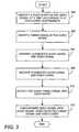
- FIG. 3is a diagram presenting a flow chart illustrating an exemplary technique for inserting and recovering synchronization information
- FIG. 4Ais a diagram illustrating exemplary video event discriminators and video events
- FIG. 4Bis a diagram illustrating a differential pulse used in selected embodiments.
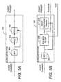
- FIGS. 5A and 5Bare diagrams illustrating two methods by which the timing signal 112 can be detected and extracted.
- FIG. 1is a diagram depicting a media distribution system 100 employing one embodiment of the present invention.
- a media program signal 106comprising an audio portion or signal 106 A and a video portion or signal 106 B is provided.
- the audio signal 106 Ais provided by an audio source 102 such as a microphone
- the video signal 106 Bis provided by a video source 104 .
- the video signal 106 B of the media program signal 106may include video segments 103 having picture information such as video frames and non-video segments 105 .
- the non-video segments 105include, for example, the closed captioning information in line 21 of the media program signal, information in the vertical blanking interval (VBI), and/or other information.
- VBIvertical blanking interval
- FIG. 1illustrates that the audio signal 106 A and the video signal 106 B may be in analog or digital form. If in analog form, the audio and video signals 106 A, 106 B may be passed through an analog-to-digital (A/D) converters 107 A and 107 B and thereafter digitally processed. Alternatively, the audio and video signals 106 A, 106 B may remain in analog form, and with further processing performed in the analog domain.
- A/Danalog-to-digital
- the video signal/data 106 B(hereinafter video signal 106 B) is provided to a video analysis module (VAM) 108 .
- the video analysis moduleidentifies video events occurring in the video signal at time t.
- the video eventcan be defined by one or more video event discriminants.
- the discriminantis a change in the luminance of all or a portion of the video signal from one frame to another frame (typically, the next frame), a temporal change in color between a portion of a video frame, or by determining a correlation (or lack of correlation) between corresponding data between a first frame and a second frame.
- the video analysis module 108provides an indication that a video event has occurred to the timing signal generator (TSG) 110 .
- the TSG 110accepts the event indication from the VAM 108 and generates a timing signal 112 in response thereto.
- the amplitude of the pulse generated by the TSG 110varies with the amplitude of the original audio signal.
- the (average) amplitude of the pulseis approximately 10-20 dB lower than the amplitude of the original audio signal.
- the VAM 108can identify different event types and provides an indicia of the event type to the TSG 110
- the TSG 110generates a timing signal having the characteristics associated with the video event type.
- the timing signal 112is provided to a mixer 114 , which adds the timing signal 112 to the audio signal 106 A to create an augmented audio signal.
- the composite audio signal and the video signalis then transmitted by the transmitter 116 , and received by receiver 118 .
- the augmented audio signalis provided to a synchronization detector 120 , which detects the timing signal.
- the video signalis provided to a second video analysis module 130 having a functionality complementary to that of the first video analysis module 108 (that is, the second video analysis module 130 , like the first video analysis module 108 accepts video data and identifies video events).
- the video eventsare provided to the synchronization detector 120 .
- the synchronization detector 120uses the video events from the second video analysis module and the detected timing signals to generate a measurement of the synchronization error, or ⁇ t, which is provided to the synchronizer 122 .
- the synchronization detector 120also determines the amplitude of the pulse.
- the synchronizer 122then delays the audio and/or video signals in accordance with the determined synchronization error as required to synchronize the audio and video signals.
- the synchronizer 122comprises a synchronization controller 128 and delay elements 124 A and 124 B.
- the synchronizer 122need have only one delay element 124 A to delay the audio signal the appropriate amount.
- the synchronizer 122need have only one delay element 124 B to delay the video signal the appropriate amount.
- the synchronizercomprises two delay elements 124 A and 124 B so that either channel may be delayed the appropriate amount.
- the delays implemented by delay elements 124 A and 124 Bcan also be used to account for any processing delays in generating, detecting, analyzing and/or using the timing signal.
- the synchronizer 122may also comprise a statistical analysis module (SAM) 132 .
- SAMstatistical analysis module
- the SAM 132collects information regarding the synchronization errors detected from the synchronization detector 120 , and uses this information to increase the accuracy or efficiency of the synchronizer.
- the SAM 132is programmed to correct for synchronization errors only when a sufficient number consecutive measurements of ⁇ t have been provided by the synchronization detector 120 .
- the SAM 132may be programmed to reject the measurements and command the synchronization controller 128 to do nothing, but if the estimated synchronization error measurements taken during another time about 15 seconds apart were 0.1, 0.2 and 0.1 seconds, the synchronization controller may be programmed to implement a suitable delay. That suitable delay could be 0.1 second (disregarding the 0.2 second data point), 0.13 second (averaging the data points), or a weighted average.
- FIG. 2is a diagram illustrating an embodiment of the media distribution system 100 in which the timing signal 112 is removed from the audio channel after it has been used for synchronization purpose and before the media program is displayed or otherwise presented to the user.
- FIG. 2also illustrates a system in which the VAM 108 also provides some indicia of the type of the video event that was detected to the TSG 110 . For example, if the discriminant was a scene change and a scene change event is detected, the VAM 108 may provide a pulse or other command to the TSG 110 at the time of the scene change, as well as information (perhaps in the form of one or more bits) to the TSG 110 to indicate that the video event that was detected was a scene change.
- the TSG 110can use this information to generate different timing signals 112 , each associated with one of the different video events.
- the different timing signalsare distinguishable from one another by the synchronization detector 120 , thus allowing the type of video event that triggered the generation of the timing signal to be recovered downstream and used for a variety of purposes.
- Thisallows use of one or more of a group of video discriminants, each having an associated timing signal.
- the timing signalis a low frequency sinusoidal pulse
- different video discriminantscan be associated with pulses of different fundamental frequencies. For example, pulses of 16, 18, 20, 22, and 24 Hz can be associated with different video discriminants.
- This informationcan be used to subtract the timing signal from the audio channel.
- the sync detector 120not only detects the presence of the timing signal 112 , but also analyzes the timing signal 112 and the video data to determine which kind of video event triggered the generation of the timing signal. This information can be used to more accurately determine the synchronization error or to generate a duplicate timing signal 112 D (using a second timing signal generator 202 ) that can be subtracted from audio signal by subtractor 204 . This effectively eliminates the timing signal 112 from the audio stream, thus rendering it either inaudible or at least, substantially reducing its audibility.
- FIG. 3is a diagram presenting a flow chart illustrating an exemplary technique for inserting and recovering synchronization information.
- a video signalis provided to the VAM 108 .
- the video signalhas at least one video event characterized by video event discriminant that takes place at time t.
- the video signalis analyzed and compared to the one or more video event discriminants to identify the video event(s).
- FIG. 4is a diagram illustrating exemplary video event discriminators and video events.
- One possible video event discriminatoris the magnitude of the luminance signal 402 .
- FIG. 4shows that a VAM 108 identifies video event 401 (indicated by the asterisk “*”) at time t when there is a temporal change in the luminance signal 402 (in the illustrated case, a rapid increase).
- FIG. 4also shows an embodiment in which video signal 106 B is characterized by a plurality of frames 404 (comprising frames 404 A- 404 D), and the video event 401 is defined as a change in the luminance of a portion 406 of the frames 404 .
- the measured luminance of portion 406 of the frame 404changes from a value of “1” to a “4” between frame 404 B and 404 C, thus indicating that a video event 401 has occurred.
- timing signal 112is in the form of a
- Video event discriminantscan be identified for different portions of the video frame as well. For example, since visible watermarks or “bugs” are often inserted by media program providers in the lower right hand corner of the frame, this portion of the video frame can be examined to identify video events 401 . For example, a persistent image in this portion of the video frame can be identified as a bug, and when that bug disappears, this may be an indication that the media program is being interrupted by a commercial or a change in programming. This may be used as a discriminant for a video event 401 . Video events 401 can also be defined using a combination of different discriminants in different portions of the frame.
- the video event 401is defined to have occurred at the end of the frame, but the video event 401 could have also been defined to be at the beginning of the frame, the beginning of the next frame, when the scanning of the portion 406 of the frame 404 in question is completed, or in the temporal center of the affected frame.
- FIG. 4also shows the application of another possible video event discriminant.
- each frame of the video signalis analyzed to determine a frame-to-frame correlation.
- the video event 401is identified. In the illustrated example, this occurs in frame 404 C. Again, the end of the frame was arbitrarily chosen as the time at which the video event 401 was identified.
- Another possible video event discriminantis a temporal change in color in a portion of a frame 404 (for example, from sky-blue to brown).
- the audio signal 106 Ais augmented with a timing signal 112 .
- the audio pulse 112is inserted at a defined time after the occurrence of the video event 401 . This is the case for at least two reasons.
- the identification of the video eventcannot occur instantaneously, as this process requires the completion of a processing algorithm or equivalent.
- the delay for such processingmust be accounted for when synchronizing the audio and video content.
- thisis accomplished by inserting the timing signal in the audio signal at a defined time that is offset from the video event. For example, if the processing were to take up to 0.05 seconds, the timing signal could be inserted into the audio signal 0.05 seconds in all cases, and the true time of the video event determined by the receiver by subtracting the 0.05 seconds from the time that the audio event is identified. This time can also be used to account for processing times required to identify and process the timing signal by the receiver.
- the timing signalbegins before it can be easily measured.
- the timing signalis in the form of a sin c pulse and the timing signal determined as the peak of the pulse.
- the audio pulse 112must begin before the peak of the audio pulse by a time t delay , which is a function of the fundamental frequency of the pulse 112 and the windowing used to create it. Since the peak occurs at a time after the pulse begins, this delay must be accounted for. This can be accomplished by inserting the timing signal at a determined time that is offset from the video event. Similar techniques are required to implement embodiments that use the differential sin c pulse for the timing signal, as described below.
- scene changes that occur faster than a pulse lengthcannot be adequately represented by the pulse, and should be ignored or processed with an audio signal with a suitably short pulse width. For example, if the audio signal is removed from the audio channel before providing it to be reproduced during viewing, a shorter (and hence, higher frequency and audible) pulse length can be used.
- block 302illustrates the insertion of a timing signal into the audio signal at a time corresponding to the identified video event 401 .
- the timing signalis provided by the timing signal generator 110 .
- the timing signalmay be generated in a number of ways, and may take a variety of forms. In one embodiment, the timing signal is a digital signal that is simply recalled from a storage. In another embodiment, the timing signal is an analog or digital signal that is generated each time it is required.
- the sinusoidal pulsemay take the form of a sin c( ⁇ t) (or
- timing signal 112it is desirable to use the timing signal 112 to reflect the relationship between the timing of the audio signal and the video signal as accurately possible, and this is best accomplished by marking the timing signal at a zero crossing rather than a peak value.
- the audio signalit is undesirable for the audio signal to include energy with significant very low frequency components (e.g. at or near DC or zero frequency). That is because few audio transmission/reproduction systems are capable of transmitting or reproducing such DC energy, as they use series-coupled capacitors that block DC energy.
- timing signalof the form of the derivative of the sin c( ⁇ t) pulse, which is defined as:
- ⁇is the selected fundamental frequency of the timing signal, which is preferably between 16 and 24 Hz.
- FIG. 4Bis a diagram showing a typical differential sin c pulse 450 .
- the differential sin c pulse 450comprises a zero crossing 454 and an amplitude peak 452 adjacent thereto.
- the spectral energy of the foregoing pulseis much like that of the sin c( ⁇ t) pulse, in that above a given cutoff frequency, there is zero energy.
- the energy in the derivative of the sin c( ⁇ t) pulsedrops off at 6 dB per octave below the cutoff frequency, and it has no DC components.
- the “peak” of its energyoccurs with a rapid transition through zero, making the peak easily detectable as a sign change adjacent one of the amplitude peaks or a sign change adjacent an energy peak.
- the differential sin c( ⁇ t) pulsestill has the disadvantage of requiring an infinitely long time to send the pulse. This can be remedied through the application of a window function to the sin c( ⁇ t) pulse.
- window functionscan be used, including rectangular, Gauss, Hamming, Hann, Bartlett, triangular, Bartlett-Hann, Blackman, Kaiser, Nuttall, Blackman-Nutall, Flat top, Bessel or Sine windows (see, for example, the windowing functions described in Wikipedia (http://en.wikipedia.org/wiki/Window_function#Hann_window) incorporated by reference herein.
- the raised cosine or Hann window functionis described in Wikipedia (http://en.wikipedia.org/wiki/Window_function#Hann_window) incorporated by reference herein.
- ⁇ ⁇ ( n )0.5 ⁇ ( 1 - cos ⁇ ( 2 ⁇ ⁇ ⁇ ⁇ ⁇ n N - 1 ) ) wherein N represents the width, in samples of a discrete-time window function, and n is an integer, with values 0 ⁇ n ⁇ N ⁇ 1.
- the pulse frequency and windowing functionmay be adjusted as desired to maximize detection while minimizing audibility. As the pulse frequency increase, the time over which the windowing function needs to be applied also increases.
- the pulsecan be of any suitable length, but must be long enough to be adequately detectable with sufficient accuracy by the synchronization detector 120 , yet short enough to allow use of the timing signal to correct errors without undue delay. In one embodiment, the pulse is between 100 milliseconds and 5 seconds in length.
- the audibility of the timing signalis reduced by applying a combination of sub-timing signals such that the sum of the sub-timing signals is zero.
- a left timing signalcan be used along with a complimentary right timing signal having the same amplitude but opposite phase of the left timing signal. Since the sum of the left and right channel signals is zero, and because low frequencies are typically not directional, the timing signal will be essentially inaudible to the user. The timing signal will also be inaudible in installations using satellite speaker and subwoofer technology because the lower frequencies are typically mixed down to monaural before being applied to the subwoofer. Also, the very low frequencies found in media programs are typically recorded in both the right and left channels in phase.
- timing signalSince the right and left channel information of the timing signal is recorded out of phase, to cancel each other out, detection of the timing signal itself may be simplified.
- Surround sound systemscomprising more than two channels can have timing signals of appropriate phase and amplitude applied to the various channels such that when summed to LT RT (left total, right total), then again to monaural, the timing signal will become inaudible.
- the augmented audio signal and video signalis transmitted by transmitter 116 , as shown in block 306 .
- the augmented audio signal and the video signalare received by the receiver 118 , as shown in block 308 .
- the video event 401is identified in the received video signal and compared to a timing signal 112 detected in the augmented audio signal as shown in block 310 , and these detected signals are used to synchronize the video signal, as shown in block 312 .
- FIGS. 5A and 5Bare diagrams illustrating two methods by which the timing signal 112 can be detected and extracted.
- a low frequency sinusoidal pulseis detected by passing the augmented audio signal through a bandpass or low-pass filter 502 having a bandpass approximating that of the timing signal's spectral content, and searching the bandfiltered signal for increased energy with a spectral density and duration matching that of the expected timing signals.
- the bandfiltered signalis then supplied to a rectifier 504 to produce a signal proportional to the absolute value of the bandfiltered signal, and thence to a processor 508 .
- the rectifier 504may, for example, be a device that determines the peak of the waveform provided by the BPF 502 and holds that value, similar to circuits that are used in power supplies, or may involve digital processing.
- the processordetermines when the timing signal energy is at its peak.
- the timing signalis a sin c(x) pulse, or other pulse having a central energy peak
- the synchronization detector 120provides an event indication when the peak is reached.
- the processorcomprises a peak and zero crossing detector, and the event indication is provided at the time as the bandfiltered signal crosses zero adjacent to the peak energy.
- FIG. 5Bis a diagram showing another embodiment of the synchronization detector 120 .
- the detectorcomprises an optional bandpass or low pass filter 502 , communicatively coupled to an optimal filter 508 such as a Kalman filter.
- the optimal filter 508is matched to the expected pulses, and is used to identify when the energy in the timing pulse is at its peak.
- Zero crossing detector 510determines the zero crossing of the timing signal nearest the point of peak energy.
- This embodiment of the synchronization detectormay also produce a value for the amplitude and type of the audio timing signal 122 , as shown. All of the foregoing operations of the sync converter 120 can also be performed by digitally using A/D converter and a digital signal processor as well.
- timing signal detection techniquescan be employed, depending on the timing signal that is used.
- the synchronization detector 120can include a corellator, which attempts to correlate the augmented audio signal with one or more known timing signals on a continuous basis. When the correlator identifies a high degree of correlation between the augmented audio signal and one of the timing signals, the synchronization detector 120 provides the event indication.
Landscapes
- Engineering & Computer Science (AREA)
- Multimedia (AREA)
- Signal Processing (AREA)
- Computer Security & Cryptography (AREA)
- Television Receiver Circuits (AREA)
Abstract
Description
(or sin c(x)) pulse, the peak of the pulse occurs at a time tdelayafter the
) pulse (where ω is the fundamental frequency of the pulse) rather than a simple sinusoid.
wherein ω is the selected fundamental frequency of the timing signal, which is preferably between 16 and 24 Hz.
wherein N represents the width, in samples of a discrete-time window function, and n is an integer, with values 0≦n≦N−1.
Claims (56)
Priority Applications (1)
| Application Number | Priority Date | Filing Date | Title |
|---|---|---|---|
| US11/529,941US7948558B2 (en) | 2006-09-29 | 2006-09-29 | Audio video timing measurement and synchronization |
Applications Claiming Priority (1)
| Application Number | Priority Date | Filing Date | Title |
|---|---|---|---|
| US11/529,941US7948558B2 (en) | 2006-09-29 | 2006-09-29 | Audio video timing measurement and synchronization |
Publications (2)
| Publication Number | Publication Date |
|---|---|
| US20080079851A1 US20080079851A1 (en) | 2008-04-03 |
| US7948558B2true US7948558B2 (en) | 2011-05-24 |
Family
ID=39260736
Family Applications (1)
| Application Number | Title | Priority Date | Filing Date |
|---|---|---|---|
| US11/529,941Active2030-02-10US7948558B2 (en) | 2006-09-29 | 2006-09-29 | Audio video timing measurement and synchronization |
Country Status (1)
| Country | Link |
|---|---|
| US (1) | US7948558B2 (en) |
Cited By (1)
| Publication number | Priority date | Publication date | Assignee | Title |
|---|---|---|---|---|
| US20100053340A1 (en)* | 2005-10-27 | 2010-03-04 | Hiroaki Ikeda | Method and device for accurately and easily measuring a time difference between video and audio |
Families Citing this family (27)
| Publication number | Priority date | Publication date | Assignee | Title |
|---|---|---|---|---|
| US8401336B2 (en) | 2001-05-04 | 2013-03-19 | Legend3D, Inc. | System and method for rapid image sequence depth enhancement with augmented computer-generated elements |
| US9286941B2 (en) | 2001-05-04 | 2016-03-15 | Legend3D, Inc. | Image sequence enhancement and motion picture project management system |
| US8897596B1 (en) | 2001-05-04 | 2014-11-25 | Legend3D, Inc. | System and method for rapid image sequence depth enhancement with translucent elements |
| WO2006101504A1 (en)* | 2004-06-22 | 2006-09-28 | Sarnoff Corporation | Method and apparatus for measuring and/or correcting audio/visual synchronization |
| US8363161B2 (en)* | 2006-05-26 | 2013-01-29 | Broadcom Corporation | Systems, methods, and apparatus for synchronization of audio and video signals |
| US8179475B2 (en)* | 2007-03-09 | 2012-05-15 | Legend3D, Inc. | Apparatus and method for synchronizing a secondary audio track to the audio track of a video source |
| US9083943B2 (en)* | 2007-06-04 | 2015-07-14 | Sri International | Method for generating test patterns for detecting and quantifying losses in video equipment |
| US8205148B1 (en)* | 2008-01-11 | 2012-06-19 | Bruce Sharpe | Methods and apparatus for temporal alignment of media |
| EP2346260A1 (en) | 2009-11-30 | 2011-07-20 | Alcatel Lucent | Method for monitoring the synchronization between a video stream and at least one audio stream of a multimedia content |
| WO2011071928A2 (en)* | 2009-12-07 | 2011-06-16 | Pixel Instruments Corporation | Dialogue detector and correction |
| US9736501B2 (en)* | 2010-03-09 | 2017-08-15 | Vijay Sathya | System and method and apparatus to detect the re-occurrence of an event and insert the most appropriate event sound |
| US8730232B2 (en) | 2011-02-01 | 2014-05-20 | Legend3D, Inc. | Director-style based 2D to 3D movie conversion system and method |
| US9241147B2 (en) | 2013-05-01 | 2016-01-19 | Legend3D, Inc. | External depth map transformation method for conversion of two-dimensional images to stereoscopic images |
| US9282321B2 (en) | 2011-02-17 | 2016-03-08 | Legend3D, Inc. | 3D model multi-reviewer system |
| US9288476B2 (en) | 2011-02-17 | 2016-03-15 | Legend3D, Inc. | System and method for real-time depth modification of stereo images of a virtual reality environment |
| US9407904B2 (en) | 2013-05-01 | 2016-08-02 | Legend3D, Inc. | Method for creating 3D virtual reality from 2D images |
| US9007365B2 (en) | 2012-11-27 | 2015-04-14 | Legend3D, Inc. | Line depth augmentation system and method for conversion of 2D images to 3D images |
| US9547937B2 (en) | 2012-11-30 | 2017-01-17 | Legend3D, Inc. | Three-dimensional annotation system and method |
| US9007404B2 (en) | 2013-03-15 | 2015-04-14 | Legend3D, Inc. | Tilt-based look around effect image enhancement method |
| US9438878B2 (en) | 2013-05-01 | 2016-09-06 | Legend3D, Inc. | Method of converting 2D video to 3D video using 3D object models |
| US10255947B2 (en)* | 2015-08-31 | 2019-04-09 | Netflix, Inc. | Mitigating drift in audiovisual assets |
| US9609307B1 (en) | 2015-09-17 | 2017-03-28 | Legend3D, Inc. | Method of converting 2D video to 3D video using machine learning |
| CN110267083B (en)* | 2019-06-18 | 2021-12-10 | 广州虎牙科技有限公司 | Audio and video synchronization detection method, device, equipment and storage medium |
| US11321904B2 (en) | 2019-08-30 | 2022-05-03 | Maxon Computer Gmbh | Methods and systems for context passing between nodes in three-dimensional modeling |
| US11714928B2 (en) | 2020-02-27 | 2023-08-01 | Maxon Computer Gmbh | Systems and methods for a self-adjusting node workspace |
| US11373369B2 (en) | 2020-09-02 | 2022-06-28 | Maxon Computer Gmbh | Systems and methods for extraction of mesh geometry from straight skeleton for beveled shapes |
| CN112188259B (en)* | 2020-09-29 | 2022-09-23 | 北京达佳互联信息技术有限公司 | Method and device for audio and video synchronization test and correction and electronic equipment |
Citations (45)
| Publication number | Priority date | Publication date | Assignee | Title |
|---|---|---|---|---|
| US4099202A (en) | 1977-05-02 | 1978-07-04 | Robot Research, Inc. | Multiplexed communication of voice signals and slow scan television signals over a common communication channel |
| US4218705A (en) | 1977-09-05 | 1980-08-19 | Nippon Electric Company, Ltd. | Delay compensator for a television signal |
| US4313135A (en) | 1980-07-28 | 1982-01-26 | Cooper J Carl | Method and apparatus for preserving or restoring audio to video synchronization |
| US4618890A (en) | 1985-01-22 | 1986-10-21 | Nec Corporation | Digital audio synchronizing system with mute time switching function |
| US4703355A (en) | 1985-09-16 | 1987-10-27 | Cooper J Carl | Audio to video timing equalizer method and apparatus |
| US4743981A (en) | 1986-01-31 | 1988-05-10 | Walt Disney Productions | System for synchronizing audiotape and videotape machines |
| US4851909A (en) | 1987-09-24 | 1989-07-25 | Robert Bosch Gmbh | Method and apparatus for maintaining audio/ video synchronism in a television signal read-out from a digital buffer memory by a reference signal |
| US4963967A (en) | 1989-03-10 | 1990-10-16 | Tektronix, Inc. | Timing audio and video signals with coincidental markers |
| US4969041A (en) | 1988-09-23 | 1990-11-06 | Dubner Computer Systems, Inc. | Embedment of data in a video signal |
| USRE33535E (en) | 1985-09-16 | 1991-02-12 | Audio to video timing equalizer method and apparatus | |
| US5091947A (en) | 1987-06-04 | 1992-02-25 | Ricoh Company, Ltd. | Speech recognition method and apparatus |
| US5243424A (en) | 1990-05-16 | 1993-09-07 | Thames Television Plc | Apparatus and method for the measurement of tuning delay between a video signal and an audio signal |
| US5365579A (en) | 1991-12-27 | 1994-11-15 | Lucasarts Entertainment Company | Method and apparatus for remote control and synchronization allowing for simultaneous remote collaboration |
| US5572261A (en) | 1995-06-07 | 1996-11-05 | Cooper; J. Carl | Automatic audio to video timing measurement device and method |
| US5642171A (en) | 1994-06-08 | 1997-06-24 | Dell Usa, L.P. | Method and apparatus for synchronizing audio and video data streams in a multimedia system |
| US5751368A (en) | 1994-10-11 | 1998-05-12 | Pixel Instruments Corp. | Delay detector apparatus and method for multiple video sources |
| US5818520A (en) | 1996-02-12 | 1998-10-06 | Tektronix, Inc. | Programmable instrument for automatic measurement of compressed video quality |
| US5880788A (en) | 1996-03-25 | 1999-03-09 | Interval Research Corporation | Automated synchronization of video image sequences to new soundtracks |
| US6097558A (en) | 1994-03-31 | 2000-08-01 | Sony Corporation | Digital audio signal transmission apparatus with data blocks of varying sizes |
| US6233389B1 (en) | 1998-07-30 | 2001-05-15 | Tivo, Inc. | Multimedia time warping system |
| US6246439B1 (en) | 1997-03-28 | 2001-06-12 | Tektronix, Inc. | Transparent embedment of data in a video signal |
| US6269122B1 (en) | 1998-01-02 | 2001-07-31 | Intel Corporation | Synchronization of related audio and video streams |
| US6330033B1 (en) | 1995-12-07 | 2001-12-11 | James Carl Cooper | Pulse detector for ascertaining the processing delay of a signal |
| US6373960B1 (en) | 1998-01-06 | 2002-04-16 | Pixel Tools Corporation | Embedding watermarks into compressed video data |
| US6407769B1 (en)* | 1998-02-12 | 2002-06-18 | John Robert Emmett | Measurement of timing delay between associated signals or bitstreams |
| US6414960B1 (en) | 1998-12-29 | 2002-07-02 | International Business Machines Corp. | Apparatus and method of in-service audio/video synchronization testing |
| US20020140859A1 (en) | 2001-03-27 | 2002-10-03 | Takaki Kariatsumari | Digital broadcast receiving apparatus and control method thereof |
| US20020140857A1 (en) | 2001-03-30 | 2002-10-03 | Limaye Ajit M. | Audio/video processing engine |
| US6480902B1 (en) | 1999-05-25 | 2002-11-12 | Institute For Information Industry | Intermedia synchronization system for communicating multimedia data in a computer network |
| US20030122964A1 (en) | 2002-01-02 | 2003-07-03 | Sony Electronics Inc. | Synchronization network, system and method for synchronizing audio |
| US20030142232A1 (en) | 2002-01-31 | 2003-07-31 | Albean David Lawrence | Audio/video system providing variable delay |
| US6697120B1 (en) | 1999-06-24 | 2004-02-24 | Koninklijke Philips Electronics N.V. | Post-synchronizing an information stream including the replacement of lip objects |
| US6757300B1 (en) | 1998-06-04 | 2004-06-29 | Innes Corporation Pty Ltd | Traffic verification system |
| US20040179043A1 (en) | 2001-04-13 | 2004-09-16 | Serge Viellescaze | Method and system for animating a figure in three dimensions |
| US20040227856A1 (en) | 2003-05-16 | 2004-11-18 | Cooper J. Carl | Method and apparatus for determining relative timing of image and associated information |
| US6836295B1 (en) | 1995-12-07 | 2004-12-28 | J. Carl Cooper | Audio to video timing measurement for MPEG type television systems |
| US6906755B2 (en) | 2002-01-04 | 2005-06-14 | Microsoft Corporation | Method and apparatus for synchronizing audio and video data |
| US6912010B2 (en) | 2002-04-15 | 2005-06-28 | Tektronix, Inc. | Automated lip sync error correction |
| US6961512B1 (en) | 1999-12-27 | 2005-11-01 | Dvd Tech Co., Ltd. | Subtitle management method for digital video disk |
| US20060007356A1 (en) | 2002-10-24 | 2006-01-12 | Thomson Licensing S.A. | Method and system for maintaining lip synchronization |
| US7020894B1 (en) | 1998-07-24 | 2006-03-28 | Leeds Technologies Limited | Video and audio synchronization |
| US7030930B2 (en) | 2001-03-06 | 2006-04-18 | Ati Technologies, Inc. | System for digitized audio stream synchronization and method thereof |
| US7043749B1 (en) | 1998-02-27 | 2006-05-09 | Tandberg Telecom As | Audio-video packet synchronization at network gateway |
| US7593061B2 (en)* | 2004-06-22 | 2009-09-22 | Sarnoff Corporation | Method and apparatus for measuring and/or correcting audio/visual synchronization |
| US7692724B2 (en)* | 2004-10-12 | 2010-04-06 | Samsung Electronics Co., Ltd. | Method and apparatus to synchronize audio and video |
- 2006
- 2006-09-29USUS11/529,941patent/US7948558B2/enactiveActive
Patent Citations (47)
| Publication number | Priority date | Publication date | Assignee | Title |
|---|---|---|---|---|
| US4099202A (en) | 1977-05-02 | 1978-07-04 | Robot Research, Inc. | Multiplexed communication of voice signals and slow scan television signals over a common communication channel |
| US4218705A (en) | 1977-09-05 | 1980-08-19 | Nippon Electric Company, Ltd. | Delay compensator for a television signal |
| US4313135A (en) | 1980-07-28 | 1982-01-26 | Cooper J Carl | Method and apparatus for preserving or restoring audio to video synchronization |
| US4313135B1 (en) | 1980-07-28 | 1996-01-02 | J Carl Cooper | Method and apparatus for preserving or restoring audio to video |
| US4618890A (en) | 1985-01-22 | 1986-10-21 | Nec Corporation | Digital audio synchronizing system with mute time switching function |
| USRE33535E (en) | 1985-09-16 | 1991-02-12 | Audio to video timing equalizer method and apparatus | |
| US4703355A (en) | 1985-09-16 | 1987-10-27 | Cooper J Carl | Audio to video timing equalizer method and apparatus |
| US4743981A (en) | 1986-01-31 | 1988-05-10 | Walt Disney Productions | System for synchronizing audiotape and videotape machines |
| US5091947A (en) | 1987-06-04 | 1992-02-25 | Ricoh Company, Ltd. | Speech recognition method and apparatus |
| US4851909A (en) | 1987-09-24 | 1989-07-25 | Robert Bosch Gmbh | Method and apparatus for maintaining audio/ video synchronism in a television signal read-out from a digital buffer memory by a reference signal |
| US4969041A (en) | 1988-09-23 | 1990-11-06 | Dubner Computer Systems, Inc. | Embedment of data in a video signal |
| US4963967A (en) | 1989-03-10 | 1990-10-16 | Tektronix, Inc. | Timing audio and video signals with coincidental markers |
| US5243424A (en) | 1990-05-16 | 1993-09-07 | Thames Television Plc | Apparatus and method for the measurement of tuning delay between a video signal and an audio signal |
| US5365579A (en) | 1991-12-27 | 1994-11-15 | Lucasarts Entertainment Company | Method and apparatus for remote control and synchronization allowing for simultaneous remote collaboration |
| US6097558A (en) | 1994-03-31 | 2000-08-01 | Sony Corporation | Digital audio signal transmission apparatus with data blocks of varying sizes |
| US5642171A (en) | 1994-06-08 | 1997-06-24 | Dell Usa, L.P. | Method and apparatus for synchronizing audio and video data streams in a multimedia system |
| US5751368A (en) | 1994-10-11 | 1998-05-12 | Pixel Instruments Corp. | Delay detector apparatus and method for multiple video sources |
| US5572261A (en) | 1995-06-07 | 1996-11-05 | Cooper; J. Carl | Automatic audio to video timing measurement device and method |
| US6836295B1 (en) | 1995-12-07 | 2004-12-28 | J. Carl Cooper | Audio to video timing measurement for MPEG type television systems |
| US6330033B1 (en) | 1995-12-07 | 2001-12-11 | James Carl Cooper | Pulse detector for ascertaining the processing delay of a signal |
| US5818520A (en) | 1996-02-12 | 1998-10-06 | Tektronix, Inc. | Programmable instrument for automatic measurement of compressed video quality |
| US5880788A (en) | 1996-03-25 | 1999-03-09 | Interval Research Corporation | Automated synchronization of video image sequences to new soundtracks |
| US6246439B1 (en) | 1997-03-28 | 2001-06-12 | Tektronix, Inc. | Transparent embedment of data in a video signal |
| US6269122B1 (en) | 1998-01-02 | 2001-07-31 | Intel Corporation | Synchronization of related audio and video streams |
| US6373960B1 (en) | 1998-01-06 | 2002-04-16 | Pixel Tools Corporation | Embedding watermarks into compressed video data |
| US6407769B1 (en)* | 1998-02-12 | 2002-06-18 | John Robert Emmett | Measurement of timing delay between associated signals or bitstreams |
| US7043749B1 (en) | 1998-02-27 | 2006-05-09 | Tandberg Telecom As | Audio-video packet synchronization at network gateway |
| US6757300B1 (en) | 1998-06-04 | 2004-06-29 | Innes Corporation Pty Ltd | Traffic verification system |
| US7020894B1 (en) | 1998-07-24 | 2006-03-28 | Leeds Technologies Limited | Video and audio synchronization |
| US6233389B1 (en) | 1998-07-30 | 2001-05-15 | Tivo, Inc. | Multimedia time warping system |
| US6414960B1 (en) | 1998-12-29 | 2002-07-02 | International Business Machines Corp. | Apparatus and method of in-service audio/video synchronization testing |
| US6480902B1 (en) | 1999-05-25 | 2002-11-12 | Institute For Information Industry | Intermedia synchronization system for communicating multimedia data in a computer network |
| US6697120B1 (en) | 1999-06-24 | 2004-02-24 | Koninklijke Philips Electronics N.V. | Post-synchronizing an information stream including the replacement of lip objects |
| US6961512B1 (en) | 1999-12-27 | 2005-11-01 | Dvd Tech Co., Ltd. | Subtitle management method for digital video disk |
| US7030930B2 (en) | 2001-03-06 | 2006-04-18 | Ati Technologies, Inc. | System for digitized audio stream synchronization and method thereof |
| US20020140859A1 (en) | 2001-03-27 | 2002-10-03 | Takaki Kariatsumari | Digital broadcast receiving apparatus and control method thereof |
| US20020140857A1 (en) | 2001-03-30 | 2002-10-03 | Limaye Ajit M. | Audio/video processing engine |
| US20040179043A1 (en) | 2001-04-13 | 2004-09-16 | Serge Viellescaze | Method and system for animating a figure in three dimensions |
| US20030122964A1 (en) | 2002-01-02 | 2003-07-03 | Sony Electronics Inc. | Synchronization network, system and method for synchronizing audio |
| US20050238059A1 (en) | 2002-01-04 | 2005-10-27 | Microsoft Corporation | Method and apparatus for synchronizing audio and video data |
| US6906755B2 (en) | 2002-01-04 | 2005-06-14 | Microsoft Corporation | Method and apparatus for synchronizing audio and video data |
| US20030142232A1 (en) | 2002-01-31 | 2003-07-31 | Albean David Lawrence | Audio/video system providing variable delay |
| US6912010B2 (en) | 2002-04-15 | 2005-06-28 | Tektronix, Inc. | Automated lip sync error correction |
| US20060007356A1 (en) | 2002-10-24 | 2006-01-12 | Thomson Licensing S.A. | Method and system for maintaining lip synchronization |
| US20040227856A1 (en) | 2003-05-16 | 2004-11-18 | Cooper J. Carl | Method and apparatus for determining relative timing of image and associated information |
| US7593061B2 (en)* | 2004-06-22 | 2009-09-22 | Sarnoff Corporation | Method and apparatus for measuring and/or correcting audio/visual synchronization |
| US7692724B2 (en)* | 2004-10-12 | 2010-04-06 | Samsung Electronics Co., Ltd. | Method and apparatus to synchronize audio and video |
Non-Patent Citations (2)
| Title |
|---|
| Notice of Allowance dated Jan. 26, 2011 in U.S. Appl. No. 11/784,758 filed Apr. 7, 2007 by Leon J. Stanger. |
| Robin, Michael et al.; "Digital Television Fundamentals-Design and Installation of Video and Audio Systems"; McGraw-Hill; Chapter 8; title page and pp. 345-425. |
Cited By (2)
| Publication number | Priority date | Publication date | Assignee | Title |
|---|---|---|---|---|
| US20100053340A1 (en)* | 2005-10-27 | 2010-03-04 | Hiroaki Ikeda | Method and device for accurately and easily measuring a time difference between video and audio |
| US8358375B2 (en)* | 2005-10-27 | 2013-01-22 | National University Corporation Chiba University | Method and device for accurately and easily measuring a time difference between video and audio |
Also Published As
| Publication number | Publication date |
|---|---|
| US20080079851A1 (en) | 2008-04-03 |
Similar Documents
| Publication | Publication Date | Title |
|---|---|---|
| US7948558B2 (en) | Audio video timing measurement and synchronization | |
| US8363161B2 (en) | Systems, methods, and apparatus for synchronization of audio and video signals | |
| US7593061B2 (en) | Method and apparatus for measuring and/or correcting audio/visual synchronization | |
| KR100694060B1 (en) | Audio video synchronization device and method | |
| CN100456818C (en) | Apparatus and method for testing lip synchronization of digital television receiver | |
| US7948559B2 (en) | Method and apparatus for lipsync measurement and correction | |
| US9692945B2 (en) | AV timing measurement and correction for digital television | |
| KR0168860B1 (en) | Automatic cm recognition device | |
| US20050219366A1 (en) | Digital audio-video differential delay and channel analyzer | |
| CN102084416B (en) | Audio visual signature, method of deriving a signature, and method of comparing audio-visual data | |
| US9111580B2 (en) | Time alignment of recorded audio signals | |
| US20070245222A1 (en) | Lip synchronization system and method | |
| MXPA03004846A (en) | Apparatus and method for measuring tuning of a digital broadcast receiver. | |
| AU5050199A (en) | Video and audio synchronisation | |
| EP4029243B1 (en) | Signal delay measurement | |
| JP2003259314A (en) | Video and audio synchronization method and system | |
| US8358375B2 (en) | Method and device for accurately and easily measuring a time difference between video and audio | |
| CN116248940A (en) | Method and system for detecting audio-video dyssynchrony of main and standby channel programs | |
| JP3944329B2 (en) | Apparatus and method for controlling and detecting alignment of composite video color frame | |
| JP5852304B2 (en) | Signature curve generating apparatus and method | |
| EP0921695B1 (en) | Video alignement using a selected partial picture | |
| EP2575371A1 (en) | Method and measurement system for evaluating a delay between audio and video signals in an audio/video stream | |
| US6407769B1 (en) | Measurement of timing delay between associated signals or bitstreams | |
| JP2662849B2 (en) | Measuring method of delay between video and audio signals by transmission path of television signal | |
| Terry et al. | Detection and correction of lip-sync errors using audio and video fingerprints |
Legal Events
| Date | Code | Title | Description |
|---|---|---|---|
| AS | Assignment | Owner name:DIRECTV GROUP, INC., THE, CALIFORNIA Free format text:ASSIGNMENT OF ASSIGNORS INTEREST;ASSIGNORS:STANGER, LEON J.;MICHENER, JAMES A.;REEL/FRAME:018493/0869;SIGNING DATES FROM 20060926 TO 20060927 Owner name:DIRECTV GROUP, INC., THE, CALIFORNIA Free format text:ASSIGNMENT OF ASSIGNORS INTEREST;ASSIGNORS:STANGER, LEON J.;MICHENER, JAMES A.;SIGNING DATES FROM 20060926 TO 20060927;REEL/FRAME:018493/0869 | |
| STCF | Information on status: patent grant | Free format text:PATENTED CASE | |
| FPAY | Fee payment | Year of fee payment:4 | |
| MAFP | Maintenance fee payment | Free format text:PAYMENT OF MAINTENANCE FEE, 8TH YEAR, LARGE ENTITY (ORIGINAL EVENT CODE: M1552); ENTITY STATUS OF PATENT OWNER: LARGE ENTITY Year of fee payment:8 | |
| AS | Assignment | Owner name:DIRECTV, LLC, CALIFORNIA Free format text:ASSIGNMENT OF ASSIGNORS INTEREST;ASSIGNOR:THE DIRECTV GROUP, INC.;REEL/FRAME:057020/0134 Effective date:20210728 | |
| AS | Assignment | Owner name:CREDIT SUISSE AG, CAYMAN ISLANDS BRANCH, AS COLLATERAL AGENT, NEW YORK Free format text:SECURITY AGREEMENT;ASSIGNOR:DIRECTV, LLC;REEL/FRAME:057695/0084 Effective date:20210802 | |
| AS | Assignment | Owner name:THE BANK OF NEW YORK MELLON TRUST COMPANY, N.A. AS COLLATERAL AGENT, TEXAS Free format text:SECURITY AGREEMENT;ASSIGNOR:DIRECTV, LLC;REEL/FRAME:058220/0531 Effective date:20210802 | |
| MAFP | Maintenance fee payment | Free format text:PAYMENT OF MAINTENANCE FEE, 12TH YEAR, LARGE ENTITY (ORIGINAL EVENT CODE: M1553); ENTITY STATUS OF PATENT OWNER: LARGE ENTITY Year of fee payment:12 | |
| AS | Assignment | Owner name:THE BANK OF NEW YORK MELLON TRUST COMPANY, N.A., AS COLLATERAL AGENT, TEXAS Free format text:SECURITY AGREEMENT;ASSIGNOR:DIRECTV, LLC;REEL/FRAME:066371/0690 Effective date:20240124 |