US7947000B2 - Cannula system for free-space navigation and method of use - Google Patents
Cannula system for free-space navigation and method of useDownload PDFInfo
- Publication number
- US7947000B2 US7947000B2US11/479,704US47970406AUS7947000B2US 7947000 B2US7947000 B2US 7947000B2US 47970406 AUS47970406 AUS 47970406AUS 7947000 B2US7947000 B2US 7947000B2
- Authority
- US
- United States
- Prior art keywords
- serial links
- distal
- links
- sheath
- core
- Prior art date
- Legal status (The legal status is an assumption and is not a legal conclusion. Google has not performed a legal analysis and makes no representation as to the accuracy of the status listed.)
- Expired - Lifetime, expires
Links
- 238000000034methodMethods0.000titleclaimsabstractdescription18
- 230000003068static effectEffects0.000claimsdescription24
- 230000003134recirculating effectEffects0.000claimsdescription23
- 230000033001locomotionEffects0.000claimsdescription20
- 230000003213activating effectEffects0.000claims2
- 238000003780insertionMethods0.000abstractdescription9
- 230000037431insertionEffects0.000abstractdescription9
- 239000000463materialSubstances0.000description34
- 239000011149active materialSubstances0.000description18
- 230000007246mechanismEffects0.000description16
- 230000006835compressionEffects0.000description13
- 238000007906compressionMethods0.000description13
- 229920001746electroactive polymerPolymers0.000description12
- 239000012530fluidSubstances0.000description11
- 230000002452interceptive effectEffects0.000description10
- 210000001519tissueAnatomy0.000description10
- 230000008859changeEffects0.000description9
- 238000006073displacement reactionMethods0.000description8
- 230000002040relaxant effectEffects0.000description8
- 238000004904shorteningMethods0.000description7
- 230000005291magnetic effectEffects0.000description6
- 239000002245particleSubstances0.000description6
- 210000003484anatomyAnatomy0.000description5
- 230000009977dual effectEffects0.000description5
- 230000000694effectsEffects0.000description5
- 238000010438heat treatmentMethods0.000description5
- 230000001965increasing effectEffects0.000description5
- 238000012546transferMethods0.000description5
- 230000007704transitionEffects0.000description5
- 210000001072colonAnatomy0.000description4
- 230000007480spreadingEffects0.000description4
- 229910045601alloyInorganic materials0.000description3
- 239000000956alloySubstances0.000description3
- 210000004556brainAnatomy0.000description3
- 238000006243chemical reactionMethods0.000description3
- 239000011248coating agentSubstances0.000description3
- 238000000576coating methodMethods0.000description3
- 238000010276constructionMethods0.000description3
- 230000001939inductive effectEffects0.000description3
- 230000008569processEffects0.000description3
- 239000000523sampleSubstances0.000description3
- 210000002784stomachAnatomy0.000description3
- 238000013459approachMethods0.000description2
- 230000036760body temperatureEffects0.000description2
- 239000004020conductorSubstances0.000description2
- 238000010586diagramMethods0.000description2
- 230000005684electric fieldEffects0.000description2
- 230000006870functionEffects0.000description2
- 239000007788liquidSubstances0.000description2
- 230000007935neutral effectEffects0.000description2
- 229910001000nickel titaniumInorganic materials0.000description2
- 239000004033plasticSubstances0.000description2
- 229920003023plasticPolymers0.000description2
- 229920000642polymerPolymers0.000description2
- 230000002829reductive effectEffects0.000description2
- 230000000284resting effectEffects0.000description2
- 229920000431shape-memory polymerPolymers0.000description2
- 210000004872soft tissueAnatomy0.000description2
- 239000007787solidSubstances0.000description2
- 229920001169thermoplasticPolymers0.000description2
- 239000004416thermosoftening plasticSubstances0.000description2
- 238000002627tracheal intubationMethods0.000description2
- 206010003658Atrial FibrillationDiseases0.000description1
- 241001631457CannulaSpecies0.000description1
- JOYRKODLDBILNP-UHFFFAOYSA-NEthyl urethaneChemical compoundCCOC(N)=OJOYRKODLDBILNP-UHFFFAOYSA-N0.000description1
- 239000002033PVDF binderSubstances0.000description1
- FAPWRFPIFSIZLT-UHFFFAOYSA-MSodium chlorideChemical compound[Na+].[Cl-]FAPWRFPIFSIZLT-UHFFFAOYSA-M0.000description1
- HZEWFHLRYVTOIW-UHFFFAOYSA-N[Ti].[Ni]Chemical compound[Ti].[Ni]HZEWFHLRYVTOIW-UHFFFAOYSA-N0.000description1
- 210000001015abdomenAnatomy0.000description1
- 210000000683abdominal cavityAnatomy0.000description1
- 238000002679ablationMethods0.000description1
- 230000004308accommodationEffects0.000description1
- 230000004913activationEffects0.000description1
- 230000002411adverseEffects0.000description1
- 238000013019agitationMethods0.000description1
- 206010003119arrhythmiaDiseases0.000description1
- 210000001367arteryAnatomy0.000description1
- 238000005452bendingMethods0.000description1
- 238000001574biopsyMethods0.000description1
- 239000008280bloodSubstances0.000description1
- 210000004369bloodAnatomy0.000description1
- 210000004204blood vesselAnatomy0.000description1
- 210000001124body fluidAnatomy0.000description1
- 239000010839body fluidSubstances0.000description1
- 210000000621bronchiAnatomy0.000description1
- 210000005242cardiac chamberAnatomy0.000description1
- 239000000919ceramicSubstances0.000description1
- 210000000275circle of willisAnatomy0.000description1
- 238000002052colonoscopyMethods0.000description1
- 230000008878couplingEffects0.000description1
- 238000010168coupling processMethods0.000description1
- 238000005859coupling reactionMethods0.000description1
- 238000013461designMethods0.000description1
- 239000003989dielectric materialSubstances0.000description1
- 239000012777electrically insulating materialSubstances0.000description1
- 230000007831electrophysiologyEffects0.000description1
- 238000002001electrophysiologyMethods0.000description1
- 230000003511endothelial effectEffects0.000description1
- 239000004794expanded polystyreneSubstances0.000description1
- 239000003302ferromagnetic materialSubstances0.000description1
- 210000003811fingerAnatomy0.000description1
- 229920002313fluoropolymerPolymers0.000description1
- 239000002783friction materialSubstances0.000description1
- 210000004247handAnatomy0.000description1
- 210000002837heart atriumAnatomy0.000description1
- 210000001308heart ventricleAnatomy0.000description1
- 229920001903high density polyethylenePolymers0.000description1
- 239000004700high-density polyethyleneSubstances0.000description1
- 230000006698inductionEffects0.000description1
- 230000002401inhibitory effectEffects0.000description1
- 239000011810insulating materialSubstances0.000description1
- 239000012212insulatorSubstances0.000description1
- 210000004072lungAnatomy0.000description1
- 210000002751lymphAnatomy0.000description1
- 238000013507mappingMethods0.000description1
- 230000013011matingEffects0.000description1
- 239000000203mixtureSubstances0.000description1
- 210000003205muscleAnatomy0.000description1
- 229920000620organic polymerPolymers0.000description1
- 229920006254polymer filmPolymers0.000description1
- 239000004810polytetrafluoroethyleneSubstances0.000description1
- 229920001343polytetrafluoroethylenePolymers0.000description1
- 210000003492pulmonary veinAnatomy0.000description1
- 230000002441reversible effectEffects0.000description1
- 239000004576sandSubstances0.000description1
- 238000007789sealingMethods0.000description1
- 238000000926separation methodMethods0.000description1
- 239000012781shape memory materialSubstances0.000description1
- 229910001285shape-memory alloyInorganic materials0.000description1
- 239000000126substanceSubstances0.000description1
- 238000001356surgical procedureMethods0.000description1
- 210000003813thumbAnatomy0.000description1
- 238000002604ultrasonographyMethods0.000description1
- 210000004291uterusAnatomy0.000description1
- 229920001285xanthan gumPolymers0.000description1
- 229940082509xanthan gumDrugs0.000description1
- 235000010493xanthan gumNutrition0.000description1
- 239000000230xanthan gumSubstances0.000description1
Images


Classifications
- A—HUMAN NECESSITIES
- A61—MEDICAL OR VETERINARY SCIENCE; HYGIENE
- A61M—DEVICES FOR INTRODUCING MEDIA INTO, OR ONTO, THE BODY; DEVICES FOR TRANSDUCING BODY MEDIA OR FOR TAKING MEDIA FROM THE BODY; DEVICES FOR PRODUCING OR ENDING SLEEP OR STUPOR
- A61M25/00—Catheters; Hollow probes
- A61M25/01—Introducing, guiding, advancing, emplacing or holding catheters
- A61M25/0105—Steering means as part of the catheter or advancing means; Markers for positioning
- A—HUMAN NECESSITIES
- A61—MEDICAL OR VETERINARY SCIENCE; HYGIENE
- A61M—DEVICES FOR INTRODUCING MEDIA INTO, OR ONTO, THE BODY; DEVICES FOR TRANSDUCING BODY MEDIA OR FOR TAKING MEDIA FROM THE BODY; DEVICES FOR PRODUCING OR ENDING SLEEP OR STUPOR
- A61M25/00—Catheters; Hollow probes
- A61M25/0021—Catheters; Hollow probes characterised by the form of the tubing
- A—HUMAN NECESSITIES
- A61—MEDICAL OR VETERINARY SCIENCE; HYGIENE
- A61M—DEVICES FOR INTRODUCING MEDIA INTO, OR ONTO, THE BODY; DEVICES FOR TRANSDUCING BODY MEDIA OR FOR TAKING MEDIA FROM THE BODY; DEVICES FOR PRODUCING OR ENDING SLEEP OR STUPOR
- A61M25/00—Catheters; Hollow probes
- A61M25/01—Introducing, guiding, advancing, emplacing or holding catheters
- A61M25/0105—Steering means as part of the catheter or advancing means; Markers for positioning
- A61M25/0133—Tip steering devices
- A61M25/0138—Tip steering devices having flexible regions as a result of weakened outer material, e.g. slots, slits, cuts, joints or coils
- A—HUMAN NECESSITIES
- A61—MEDICAL OR VETERINARY SCIENCE; HYGIENE
- A61M—DEVICES FOR INTRODUCING MEDIA INTO, OR ONTO, THE BODY; DEVICES FOR TRANSDUCING BODY MEDIA OR FOR TAKING MEDIA FROM THE BODY; DEVICES FOR PRODUCING OR ENDING SLEEP OR STUPOR
- A61M25/00—Catheters; Hollow probes
- A61M25/01—Introducing, guiding, advancing, emplacing or holding catheters
- A61M25/0105—Steering means as part of the catheter or advancing means; Markers for positioning
- A61M25/0133—Tip steering devices
- A61M25/0147—Tip steering devices with movable mechanical means, e.g. pull wires
- A—HUMAN NECESSITIES
- A61—MEDICAL OR VETERINARY SCIENCE; HYGIENE
- A61M—DEVICES FOR INTRODUCING MEDIA INTO, OR ONTO, THE BODY; DEVICES FOR TRANSDUCING BODY MEDIA OR FOR TAKING MEDIA FROM THE BODY; DEVICES FOR PRODUCING OR ENDING SLEEP OR STUPOR
- A61M25/00—Catheters; Hollow probes
- A61M25/01—Introducing, guiding, advancing, emplacing or holding catheters
- A61M25/0105—Steering means as part of the catheter or advancing means; Markers for positioning
- A61M25/0133—Tip steering devices
- A61M25/0158—Tip steering devices with magnetic or electrical means, e.g. by using piezo materials, electroactive polymers, magnetic materials or by heating of shape memory materials
Definitions
- the present inventionrelates to devices, systems, and processes useful for exploration of hollow body structures, particularly those areas accessed through a tortuous, unsupported path. More particularly, the present invention relates to a shape-transferring cannula device that creates a custom-contoured access port for insertion and removal of diagnostic, surgical, or interventional instruments to and from a site within the body to which the physician does not have line-of-sight access.
- Surgical cannulasare well known in the art. Such devices generally include tube-like members that are inserted into openings made in the body so as to line the openings and maintain them against closure. Surgical cannulae can be used for a wide variety of purposes, and their particular construction tends to vary accordingly (see, e.g., U.S. Pat. No. 5,911,714). Flexible endoscopes, endovascular catheters and guidewires, and trocar cannulae such as those used in laparascopic surgery, are examples of such devices. Several U.S. patents recite such devices. See, for example, U.S. Pat. Nos. 5,482,029; 5,681,260; 5,766,163; 5,820,623; 5,921,915; 5,976,074; 5,976,146; 6,007,519; 6,071,234; and 6,206,872.
- the endoscopeis either significantly stiffer than the body cavity tissue it is being guided through or, as is the case for the stomach or an insufflated abdomen, the body cavity is sufficiently spacious that the endoscope has no walls at all to guide it.
- the endoscopeforces the anatomy to take painful, unnatural shapes.
- the endoscopebuckles and forms “loops” when the colonoscopist attempts to traverse tight corners. Pushing on the end of the flexible endoscope tends to grow the loop rather than advance the endoscope. “Pushing through the loop” relies on the colon to absorb potentially damaging shapes of force to advance the endoscope.
- the endoscopemay not reach its intended target at all, leaving the patient at risk of undiagnosed and potentially cancerous polyps.
- Endovascular cathetershave drawbacks as well. While generally flexible enough to avoid seriously damaging the vessel's endothelial surface, guidewires are difficult to guide into small side branches of large vessels such as the coronary ostia or into relatively small vessels connecting to relatively large chambers such as the pulmonary veins. Catheters are even more limited in their ability to deal with greatly tortuous vessel anatomy such as the vessels radiating from the brain's so-called Circle of Willis.
- U.S. Pat. No. 5,251,611discloses the use of one or more rigidizable conduits for conducting exploratory procedures.
- a particular rigidizable conduit disclosed by Zehelincludes a series of nested segments that are traversed by a plurality of cables or wires. Tension is applied to the wires to press the segments together, thereby producing a stiffened conduit. A side effect of the compression reaction to the applied tension is a shortening of the conduit as the segments are pressed together. For procedures involving an instrument that is inserted in the conduit, the shortening of the conduit will result in a change in the relative position of the instrument and the conduit. This change in relative position may have an adverse effect on the placement or use of the instrument.
- Ablation and EKG mapping catheters used in cardiological electrophysiologyfind their intended targets chiefly by trial and error insertion and twisting of a guidewire/catheter accompanied by gross motions of the entire catheter.
- cannula systemsthat can follow a tortuous path through hollow soft-tissue structures without relying on the surrounding tissue to mechanically support and guide its insertion and may be steered and advanced directly to an anatomical point of interest.
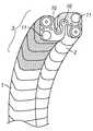
- FIG. 1is a diagrammatic sectional view of the shape transferring cannula system illustrating the major components.
- FIGS. 2A-2Dillustrate diagrammatic sectional representations of a sequence of rigidizing structure stiffening, relaxing, and advancement that enables guiding of the shape transferring cannula.
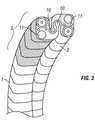
- FIG. 3is a perspective view of an embodiment of laterally parallel rigidizing core and sheath linkage structures.
- FIGS. 4A and 4Billustrate perspective views of captured-link rigidizing linkages.
- FIG. 5is a perspective view of a cable-rigidized core linkage.
- FIG. 6shows perspective and sectional views of a cable-rigidized sheath linkage.
- FIG. 7is a sectional view of an off-axis tensioning mechanism for a cable-rigidized sheath linkage.
- FIG. 8is a perspective view of an alternate embodiment of a laterally parallel sheath linkage.
- FIG. 9is a sectional view of a laterally parallel sheath linkage.
- FIG. 10shows perspective and end views of an open-sided sheath linkage.
- FIG. 11is a perspective view of a laterally parallel sheath linkage with compliant elements.
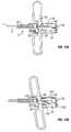
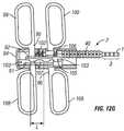
- FIGS. 12A-12Hillustrate various views of an alternating advancement mechanism in accordance with the present invention.
- FIGS. 13A-13Cis a perspective view of a rotating link cannula structure
- FIGS. 14A-14Cis a diagrammatic view of a cannula structure including a passive element.
- FIG. 15is a sectional view of a continuous stiffening cannula structure.
- FIG. 16is a perspective view of a cannula structure formed with normally-rigid, thermally relaxing materials.
- FIGS. 17A and 17Billustrate sectional views of vacuum-stiffening cannula structure elements.
- FIG. 18is a sectional view of a pressure-stiffening cannula structure.
- FIGS. 19A and 19Bshow a sectional view of normally-rigid, vibrationally relaxing cannula structure elements.
- FIGS. 20A and 20Billustrate sectional views of a cannula structure including active material elements.
- FIG. 21is a perspective view of two-axis pivoting links.
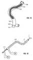
- FIG. 22depicts a catheter with a shape-transferring section.
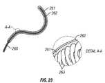
- FIG. 23depicts a thermally relaxing normally-rigid structure.
- FIG. 24depicts a motorized advancement mechanism.
- FIG. 25depicts a rigidizable cannula with distal recirculation.
- FIG. 26depicts a rigidizable cannula with proximal recirculation.
- FIG. 27depicts a rigidizable cannula with dual recirculation.
- FIG. 28depicts a rigidizable cannula wiper tip with distal recirculation.
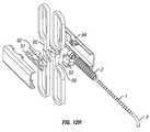
- FIG. 29depicts a dual cannula system with an endoscope liner and external cover.
- FIG. 30Adepicts an endoscope with handle and actuators for dual cannula system in an extended configuration.
- FIG. 30Bdepicts an endoscope with handle and actuators for dual cannula system in a retracted configuration.
- FIG. 31Adepicts a cannula system with an endoscope and reference frame handle in a relaxed configuration.
- FIG. 31Bdepicts a cannula system with an endoscope and reference frame handle in a rigidized configuration.
- FIG. 32depicts a flow diagram of a method embodiment in accordance with the present invention.
- FIG. 33Adepicts an endoscope with a cannula system including a distal inflatable balloon.
- FIG. 33Bdepicts an endoscope with an inflatable balloon and a cannula system with a distal inflatable balloon.
- the present inventionis directed to a novel shape-transferring cannula system, which provides access to tortuous and unsupported paths.
- the shape-transferring cannula system and methodenables exploration of hollow body structures, and creates a custom-contoured access port for insertion and removal of, for example, diagnostic, surgical, or interventional instruments to and from a site within the body to which the physician does not have line-of-sight access.
- the shape-transferring cannulacan follow a tortuous path through hollow soft-tissue structures without relying on the surrounding tissue to mechanically support and guide its insertion.
- the systemincludes two parallel rigidizing sections that alternatingly stiffen and relax with respect to one another and alternatingly transfer the path shape traced-out by the articulating tip to one another.
- a steerable articulated tipis attached to one of the rigidizing sections.
- the cannula's custom shapeis formed by guiding the articulated tip along a desired path direction, stiffening the attached rigidizing section, and advancing the other rigidizing section along the stiffened section.
- the end of the shape-transferring cannulamay be steered and advanced directly to an anatomical point of interest.
- the usertraces a path for the shape-transferring cannula with the steerable tip and in doing so defines the longitudinal shape assumed by the cannula, thus directing the working end of the cannula to a target site without substantially disturbing the length of cannula behind it.
- the ability to localize movements to the user-controlled tip of the cannulais especially valuable when working within particularly sensitive open structures such as the ventricles of the brain or loosely supported, tortuous structures such as the colon that provide very little mechanical support for intubation around corners.
- the shape-transferring cannula systemassumes the shape traced by the path of the articulating tip in an incremental fashion, with the core and sheath rigidizing structures transferring the traced path shape back and forth to each other. Having reached the target site, the external sheath can be made flexible and slid out over the rigidized central core. Unlike the lengthy re-intubation procedure for a conventional flexible endoscope, returning to the target site is simply a matter of sliding the sheath or surgical instruments over the core that now acts as a guidewire. Alternately, the sheath may be left rigid and in place once having reached the target site and the core may be made flexible and removed. This leaves the shaped sheath to act as a cannula through which surgical instruments such as snares, ultrasound probes, biopsy probes and other diagnostic devices, electrocautery tools, and the like may be transferred to and from the target site.
- surgical instrumentssuch as snares, ultrasound probes, biopsy probes and other diagnostic devices, electrocautery tools,
- the rigidizing sheath structuremay be used on its own as a rigidizing cannula when introduced to a target site by a conventional guidewire, flexible endoscope, or similar introduction element.
- the rigidizing cannuladoes not have a predetermined longitudinal shape.
- the rigidizing cannulamay support reaction forces like a rigid cannula when tools are run down its length, thus protecting sensitive tissue structures.
- FIG. 1depicts a preferred embodiment of a shape-transferring cannula system Id having two parallel rigidizing core 1 and sheath 2 structures, a steerable articulated tip 3 attached to one of the rigidizing structures, a proximal end 1 a , a distal end 1 b and a lumen 1 c through which surgical tools may be introduced or through which the target site may be irrigated or suctioned.
- the core 1 and sheath 2are parallel structures that can be coaxial or side-by-side and that may be made rigid or flexible with respect to one another.
- the core and sheath structuresmay be unitary materials or continuous structures, or they can be formed of individual, flexibly connected rigid links.
- the core and sheath structureemploys rigidizing cables which, when put into tension, pull the links together to increase friction between links and prevent relative motion between the links.
- the core's rigidizing structureis built-up of links such that a convex spherical surface on one link engages a concave surface on an adjacent link.
- the core's rigidizing cableruns through each core link's central orifice, connecting the entire core rigidizing structure.
- the core link's central orificehas a diameter D 1 that is in the range from about 0.5 mm to about 30 mm.
- a typical endoscope employing structures in accordance with the present inventionmay have an inner diameter from about 1 ⁇ 4 inch to about 1 ⁇ 2 inch, although larger or smaller sizes may also be suitable.
- the systememploys a method of incremental advancement to deliver the distal end 1 b of the cannula to a target site.
- the core 1 and sheath 2 rigidizing structuresare alternatingly advanced, one structure past the other, the stationary structure being made rigid and acting as a guide for the advancing flexible structure.
- the steerable tip assembly 3is located on the end of at least one of the two rigidizing structures such as the core 1 as depicted in FIG. 1 .
- the steerable tip 3may be actuated via cables or other tension members, magnetostrictive materials, bimetallic strips or other flexing elements, piezoelectric polymer films or ceramics, shape memory materials such as nickel-titanium shape memory alloys or shape memory polymers, electroactive artificial muscle polymers, or the like.
- the length of the steerable tip 3 and the length L, described elsewhere herein,are preferably mutually selected to be about the same length, so that the cannula can follow and track the steerable tip (see FIG. 12G ).
- the overall length of the cannulawill vary according to the particular hollow body structure for which it is intended.
- the shape-transfer cannula lengthmight range from 100 cm to 180 cm.
- the shape-transfer cannula lengthmight range from about 30 cm to about 100 cm.
- the rigidizing core 1 and sheath 2 components of a shape-transfer cannulamight be limited to a relatively small section of the entire catheter length, as depicted in FIG. 22 .
- the core 1 and sheath 2can be provided only at the distalmost end of the device or apparatus that is intended to be steered.
- the majority of the cannula's lengthmight include “passive” conventional extruded catheter material 251 and a non-rigidizing section of core 252 .
- the extra control provided by the shape-transferring core 1 and sheath 2 componentsmight only be needed within the ventricles themselves so the length of the rigidizing section R, need only be sufficient to navigate within the ventricles themselves.
- the distal, steerable portion of the apparatushas a shape-transforming length L and an outer diameter D, with the ratio L/D being at least about 5 (L/D>5), so that there is enough longitudinal length of the shape-transforming portion of the device or apparatus to track the steerable tip 3 .
- FIG. 2illustrates by way of example a sequence in which the core 1 and sheath 2 alternate sequentially between rigid and flexible such that the entire structure takes the shape traced by the steerable tip 3 as the shape-transferring cannula is inserted into a hollow body structure such as the colon, stomach, lung bronchi, uterus, abdominal cavity, brain ventricle, heart chamber, blood vessel, or the like.
- the sheath 2is rigid and the core 1 with steerable tip 3 is flexible.
- the steerable tip 3initially lies within and is approximately flush with the distal end 1 b of the sheath 2 such that both the sheath 2 and core 1 assume the same longitudinal shape whether curved or straight.
- the core 1is advanced distally through the rigidized sheath 2 , exposing the length of the steerable tip 3 .
- the userthen directs the exposed steerable tip 3 in the desired direction of insertion and advances the structure with, for example, a squeeze advancement mechanism (which will be discussed later herein) or through a cam mechanism or through any other structure or mechanism that rigidizes and relaxes the core 1 and sheath 2 in proper sequence.
- a squeeze advancement mechanismwhich will be discussed later herein
- cam mechanismor through any other structure or mechanism that rigidizes and relaxes the core 1 and sheath 2 in proper sequence.
- the sheathis advanced over the core 1 and steerable tip 3 .
- the longitudinal relative motion between the two rigidizing elementsi.e. core 1 and sheath 2
- the sheath 2is then made rigid and the core 1 is relaxed and advanced to re-expose the steerable tip 3 .
- the rigidizing structure portion of the shape-transferring cannula 1 dtakes the shape of the path traced by the steerable tip 3 as guided by the user.
- the sheath 2 and core 1may be normally-stiff structures that momentarily become flexible at appropriate times in the shape-transferring cannula advancement sequence.
- the sheath 2 and core 1may be normally-flexible structures that momentarily become rigid at appropriate times to complete the advancement sequence.
- the core 1 and sheath 2may both include a steerable tip 3 providing each structure with both directional control and the momentary rigidity necessary for shape-transference
- FIG. 3depicts an alternative embodiment of a shape-transferring cannula system in accordance with the present invention.
- the shape-transferring core 1 and sheath 2are not necessarily coaxial structures and may be laterally parallel structures that slidably engage each other longitudinally via engagement features 10 .
- engagement features in accordance with the present inventioninclude structures that permit the core 1 and sheath 2 to slide or otherwise move longitudinally relative to each other.
- One aspect of engagement features in accordance with the present inventionthat one of the core 1 and sheath 2 provides a rail for advancement of the other of the core and sheath relative thereto.
- At least one of the shape-transferring structuresincludes a steerable tip 3 with which to guide advancement of the system.
- Either or both of the shape-transferring structurescan contain accessory lumens 11 through which surgical tools may be introduced or through which the target site may be irrigated or suctioned.
- the engagement feature 10 of either structurecan be used as a guide for withdrawing samples or inserting tools that won't fit through the accessory lumen 11 .
- Outsized toolsmay be provided with compatible engagement features such that they track along the guide formed by the rigidizing structure's engagement features.
- the user's selection of an advancement direction and his actuation of the systemcauses the entire cycle of core rigidization, sheath relaxation, sheath advancement, sheath rigidization, and core relaxation to occur such that the structure is returned to its initial state with a new longitudinal shape.
- the core and sheath structuresmay be unitary materials or continuous structures that can be transformed between relatively rigid and relatively flexible or they can be formed of individual, flexibly connected rigid links which become substantially locked together to rigidize the structure.
- the sheath and core linkage structuresare rigidized by temporarily preventing, by any suitable mechanism, substantial relative motion between the links.
- motion between linksmay be temporarily stopped or substantially reduced by tightening a tension cable to put the linkage into longitudinal compression, by electrostatic or magnetic forces, by hydraulic or pneumatic actuation, by changes in viscous coupling as with electrorheological or magnetorheological materials, or through any friction modulating means.
- Linkagesmay be held together by a flexible internal cable or external covering, or by attaching the links to each other while leaving enough freedom of rotation to make the structure longitudinally flexible. More specifically as shown in FIGS. 4A and 4B , the links may be loosely captured by overlapping ball and cup features in adjacent links such that the cup features 22 overlap past the equators of the adjacent ball features 23 . This arrangement allows two-axis pivoting between links while keeping the linkage intact.
- FIG. 4Aillustrates a specific example of a rigidizing mechanism where sheath and core rigidizing linkage structures may include a compression element 20 in each link, such as a loop of nickel-titanium alloy wire or shape memory polymer whose shape-memory transition temperature is higher than normal body temperatures.
- a slot 24 in the cup 22may facilitate compression of the cup against the ball 23 when the compression element 20 is actuated.
- the compression elements 20 in the linksmay be actuated through electrical or inductive heating or through any suitable means to activate the shape-memory effect such that the compression elements reduce their unstressed diameters, creating local compression between ball and cup, and thus increasing friction between links.
- FIG. 4Billustrates another example of a rigidizing mechanism employing the same type of captured-link linkage configuration as the previous example.
- either the ball 23 or the cup 22can include active material components 25 made of materials such as electroactive polymer (EAP) that change shape when energized.
- the active material componentsmay be oriented to expand radially when energized, causing interference between the ball and cup of adjacent links.
- the active material components 25may be oriented to contract radially when energized, relieving interference between the ball and cup features of adjacent links.
- linkages built of links made of dielectric materialsmay be rigidized electrostatically by building attractive or repulsive charges between links and increasing friction between links.
- inducing magnetic attraction or repulsion between links containing ferromagnetic materialscan stiffen a rigidizing linkage by increasing friction between the links.
- linkages built with links made of conductive materialsmay be rigidized by inducing eddy currents that attract links to each other and increase friction between links.
- FIGS. 5 and 6illustrate a linkage embodiment of parallel rigidizing sheath and core structure that employs rigidizing wires or cables 34 and 40 , which go through the core 1 and sheath 2 respectively. These cables, when put into tension, pull the links together to increase friction between the links and thus prevent relative motion between the links. When not in tension, the rigidizing cables serve to hold the individual links in the rigidizing assembly together.
- the core's rigidizing structure 30is built-up of links such that a convex spherical surface 31 on one link engages a concave surface 32 on the adjacent link.
- FIG. 5shows cup-like nesting links 33 with a spherical ball-joint-like interface that allows two-axis pivoting between abutting links, thus making the linkage longitudinally flexible.
- the core's rigidizing cable 34runs through each core link's central orifice 35 , connecting the entire core rigidizing structure 30 .
- the steerable tip 3 control cables 36may also run through each link's central orifice 35 .
- the control cables 36may be mechanical cables transmitting tension or compression, or electrical connections transmitting power or signal to actuate or control the steerable tip 3 .
- the rigidizing cable 34 and tip-steering cable 36may be contained within individual lumens of a multilumen housing or within individual housings, keeping them separated and keeping the tip-steering cables 36 from binding when the rigidizing cable 34 is tensioned to stiffen the core structure.
- the housing materialmay be chosen for low friction cable movement.
- One lumen of the multilumen housingmight also serve to guide the core 1 along a conventional guidewire for rapid insertion into guidewire accessible anatomy such as the atria and ventricles of the heart.
- links 240 with male 241 and female 242 pivot features that each rotate on only one axiscan be alternated and mounted within each other, within the rigidizing structure, with adjacent pivot features having axes perpendicular to one another.
- each pair of links 240provides two orthogonal pivoting axes to the linkage structure.
- FIG. 6illustrates a linkage embodiment of the sheath 2 in which the sheath links include a hollow central orifice 41 and pivot on spherical ball joint like ball 48 and cup 47 surfaces for two-axis pivoting.
- the sheath's rigidizing cable 40runs outside each sheath 2 link's central orifice 41 allowing the assembled links to form a hollow central lumen 42 that can be occupied by the core 1 structure during cannula advancement as well as by items such as surgical instruments which the sheath lumen 42 can guide to a surgical or diagnostic site.
- the link's central orifice 41has a diameter D 2 that is substantially similar to diameter Dl, described above.
- the rigidizing sheath links 45may include at least two cable-guiding features 44 external to the central lumen 42 .
- the cable 40 and cable-guiding features 44are configured for low friction sliding. Friction may be further reduced by encasing the cable in a cable housing formed of a material with low-friction properties, such as PTFE, HDPE, and the like, thus separating it from the cable-guiding features 44 .
- the cable-guiding featuresthemselves could be manufactured from low friction materials different from that of the rest of the links.
- cables 40do not run down the central axis of the sheath 2 , cables running on opposite sides of the sheath 2 must effectively change length when the sheath 2 bends. Cable segments closer to the center of curvature relative to the structure's neutral axis will have to shorten. Likewise, cable segments further from the center of curvature relative to the sheath's 2 neutral axis will have to lengthen.
- An embodiment of a linkage sheath with two cable-guiding channels an equal radial distance from the sheath's central axismay employ the single cable 40 wrapping around a pulley 43 , which may be a rotating component, sliding surface, or the like, to run back and forth along the length of both cable-guiding channels.
- a pulley 43which may be a rotating component, sliding surface, or the like.
- the inner cable pathwill shorten the same amount as the outer cable path lengthens and cable length will move from the shortening side around the pulley 43 to the lengthening side.
- Tension on the pulley 43 with respect to the linkage structure 46tightens the entire cable 40 and stiffens the sheath 2 by increasing friction between the links. Referring to FIG.
- the sheath's tensioning pulley 43may be positioned off-axis such that the sheath central lumen 42 is clear and able to receive the core 1 or surgical instruments.
- a cable-guiding element 50 at the base of the sheath 2acts to redirect the tensioning cable 40 to an off-axis pulley 43 and away from the sheath's central lumen 42 .
- the sheath rigidizing linkage structure 60may run parallel to the core 1 without being coaxial with it.
- Each linkmay include dedicated rigidizing features 61 through which a rigidizing cable 62 may run and at least one lateral orifice 62 which, when multiply assembled in the complete linkage, form a laterally parallel segmented lumen through which the core 1 or surgical tools may run.
- the lateral orifice 62has a diameter D 3 , which is substantially similar to diameter D 1 , described above.
- FIG. 9depicts a laterally parallel sheath linkage.
- the laterally parallel sheath 60 amay form a lateral lumen 70 capable of forming varying radii of curvature by nesting conical shapes that form the lateral lumen 70 , leaving sufficient mechanical clearance 71 to accommodate an angle ⁇ between adjacent links.
- the angle ⁇is preferably in the range from about zero degrees to about 90 degrees.
- the lateral lumen diameter D 4is substantially similar to diameter D 1 , described above.
- FIG. 10depicts an alternate embodiment of a linkage.
- Linkage 82 with the parallel lateral lumen 70may include an open side 80 such that objects 81 larger than the lumen diameter D 4 may be introduced to and withdrawn from the surgical or diagnostic site using the combinations of the open sides 80 to retain therein a matching portion 83 on the object 81 .
- FIG. 11depicts another alternate embodiment of a linkage.
- Linkage 82 a with the parallel lateral lumen 70may employ flexible elements 90 in the lumen portion of each link that partially overlap each adjacent link.
- the flexible elementsserve to form a smoother and larger segmented lumen than would be formed by purely rigid links by flexing when formed into a radius rather than requiring clearance for the entire range of motion between the links.
- a mechanism for advancing parallel rigidizing elementsmay include two opposing racks 91 and 92 that alternatingly advance relative to each other.
- the maximum amount of incremental advancement, length ‘L’is ideally limited to the length of cannula having the steerable tip 3 .
- a linearly sliding shuttle 93supports one rack and a housing 94 supports the other rack.
- the core actuation handle 95(not shown for clarity in FIG. 12A and FIG. 12B ) and core rack 91 are each pivotally attached to the housing 94 .
- the sheath actuation handle 96 and sheath rack 92are each pivotally attached to the shuttle 93 .
- the core and sheath actuation handles 95 and 96are attached to the rigidizing cables 40 and 34 of the sheath 2 and core 1 , respectively. Upon actuation by the user, these handles rotate on their pivots 97 and 98 to first relax their respective rigidizing structure, disengage their respective rack from the other, which remains temporarily fixed, and transmit the force which slides the housing 94 and shuttle 93 with respect to one another to advance the shape-transferring cannula.
- the sheath rack 92is rotated away from the core rack 91 by the force of the sheath rack lifter 115 , which extends from the sheath handle 96 , acting against the rack's lift tab 117 .
- An initial gap between the sheath rack lifter 115 and rack's lift tab 117allows the sheath handle 96 to rotate enough to compress the sheath rigidizing spring 106 and relax the sheath 2 before the sheath rack 92 is disengaged from the core rack 91 .
- continued spreading of the actuation handles 95 and 96with racks 91 and 92 disengaged, translates the handles apart from each other and advances the shuttle 93 and sheath 2 relative to the housing 94 and core 1 .
- releasing the handle spreading pressureallows the sheath rigidizing spring 106 to rotate the sheath handle 96 back to its resting position and re-stiffen the sheath 2 by tensioning the sheath rigidizing cable 40 .
- the rotation of the sheath handle 96rotates the sheath rack lifter 115 away from the sheath rack 92 , allowing the sheath rack bias spring 113 to rotate the sheath rack 92 towards the core rack 91 .
- Re-engagement of the rackslocks the mechanism in a sheath-forward position shown in FIG. 12D .
- the core rack 91is rotated away from the sheath rack 92 by the force of the core rack lifter 114 , which extends from the core handle 95 , acting against the rack's lift tab 116 .
- An initial gap between the lifter 114 and lift tab 116allows the core handle 95 to rotate enough to compress the core rigidizing spring 102 and relax the core 1 before the core rack 91 is disengaged from the sheath rack 92 .
- the racks 91 and 92being disengaged from each other, continued squeezing as shown in FIG. 12F translates the handles 95 and 96 closer together by advancing the housing 94 and core 1 relative to the shuttle 93 and sheath 2 .
- the difference in engaged length of the racks 91 and 92 between the sheath-back position and the sheath-forward position, length ‘L’, as well as the position of the sliding stop structures 110 and 111 in the housing 94 and shuttle 93define the maximum relative motion for incremental advancement between the sheath 2 and core 1 elements.
- the amount of incremental advancement, length ‘L’,is preferably limited to the length of the steerable tip 3 .
- Rack features 107such as teeth define the increments in which the shape-transferring cannula may be mechanically advanced or retracted.
- the rack features 107may be configured to allow only integral advancement of units the length of the entire steerable tip 3 as shown in FIG. 12G or, alternately, may be configured allow units of advancement fractions of that length.
- the rack mechanism described abovemay also withdraw the shape-transferring cannula in controlled increments through a process reversing the advancement sequence.
- Withdrawal of hand-holds 108 and 109 on the ends of the handles 95 and 96 opposite the advancement endsactuate the mechanism in reverse using the same gripping and spreading finger/thumb motions used to advance the cannula.
- FIGS. 20A and 20Bdepict rigidizing structures including inner and outer concentric tubes, 221 and 222 respectively, separated by short segments of materials 223 that change shape when energized, such as electroactive polymer (EAP), which changes shape when exposed to electric fields.
- EAPelectroactive polymer
- the inner tube 221may or may not have an open lumen.
- the active material componentsare oriented to contract longitudinally and expand radially when energized.
- the active material componentsmay be employed in a normally-non-interfering configuration or a normally-interfering configuration.
- the active material components 223are each attached to one of the concentric tubes 221 or 222 such that they do not contact the other tube, as shown in FIG. 20A , when not energized.
- the radial expansion of the active material components 223causes mechanical interference with the other tube, as in FIG. 20B , thus preventing motion between the opposed surfaces 224 and 225 and effectively locking-in the curvature of the rigidizing structure.
- onemay substitute materials that change shape when exposed to electric current, magnetic fields, light, or other energy sources.
- the same rigidizing effectmay be achieved by replacing normally-non-interfering active material components 223 with non-interfering balloons expandable by gas or liquid fluid pressure.
- such materialsmay be placed in a normally-interfering configuration between concentric tubes 221 and 222 such that they interfere, as in FIG. 20B when not energized and contract radially to the state depicted in FIG. 20A when energized.
- a normally-rigid structure made stiff by normally-interfering EAP components 223may be made flexible by applying a voltage to the EAP components such that they contract radially to the non-interfering state depicted in FIG. 20A , relieving the mechanical interference and allowing relative motion between the opposed surfaces 224 and 225 of the concentric tubes 221 and 222 .
- normally-interfering balloons replacing normally-interfering active material components 223may be collapsed by applying a relative vacuum.
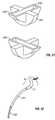
- the rigidizing sheath 2can include rotating wedge links 130 .
- the wedge links 130have hollow central axes 131 that form the sheath's lumen 42 as well as two interface features 132 angled with respect to one another.
- the angle between the linkscan be between about zero degrees and about 90 degrees.
- the perpendicular centerlines 133 of the interface surfacesdefine axes of rotation between the links.
- the wedge links 130 in a sample starting position in FIG. 13Brotate with respect to neighboring links 134 at the connecting interface 132 between links. This rotation forms curves as shown in FIG.
- the wedge links 130may be formed as sections of spheres as shown in FIG. 13A to avoid creating sharp corners when curves are formed, leaving a relatively smooth and atraumatic outer surface.
- FIGS. 14A-14Cdepict another embodiment of the invention in which one of the two parallel elements in the shape-transferring cannula is passive.
- the passive elementis more rigid than the relaxed rigidizing structure and more flexible than the stiffened rigidizing structure.
- the passive elementis less mechanically complex than an equivalent rigidizing structure, not requiring rigidizing cables 34 and 40 or other mechanisms to serve the shape-transfer function.
- a shaped cannula assembly with a passive sheathmay be narrower in cross-section than an assembly formed of two rigidizing structures.
- the core 1is relaxed such that it is more flexible than the sheath 2 and has been advanced such that the steerable tip 3 protrudes ahead of the sheath 2 .
- FIG. 14Athe core 1 is relaxed such that it is more flexible than the sheath 2 and has been advanced such that the steerable tip 3 protrudes ahead of the sheath 2 .
- FIG. 14Athe core 1 is relaxed such that it is more flexible than the sheath 2 and has been advanced such that the steerable tip 3
- the core 1is stiffened such that it is more rigid than the sheath 2 and the user deflects the steerable tip 3 towards the direction of intended cannula advancement.
- FIG. 14Cthe core 1 remains stiffened such that it is more rigid than the sheath 2 and the sheath is then advanced over the core and its steerable tip 3 .
- the sheath 2assumes the core's longitudinal shape including the new bend introduced by the user through the deflected steerable tip 3 .
- Elements of a passive link structurecould be mechanically energized to encourage them to move relative to one another when being advanced past a relatively rigid structure. Mechanical energizing can be achieved by vibrating the passive structure with any suitable device, such as a piezoelectric transducer, voicecoil, or eccentrically weighted motor.
- Embodiments of the invention that employ continuous, non-segmented, parallel core and sheath structurescan be made smaller in cross-section than mechanically-stiffened linkage structures.
- Such structuresmay be constructed such that they become relatively rigid when energized or become relatively flexible when energized.
- FIG. 15depicts a continuous, parallel shape-transferring core and sheath structure.
- the core 1 and sheath 2 structurescan each include inner 151 and outer 152 flexible tubes containing stiffening material 153 that increases in viscosity or otherwise stiffens when energized. Examples of such substances are electrorheological fluid, which stiffens upon exposure to electrical potential, and magnetorheological fluid, which stiffens upon exposure to magnetic fields.
- a rigidizing structure configured as a core or as a sheathmay be built-up of inner 151 and outer 152 containment tubes with stiffening material 153 sandwiched in between.
- the inner tubemay be a solid element such as plastic monofilament, lacking a lumen.
- flexible electrical contactsmay line the length of each containment tube or the tube itself may be made of electrically-conductive plastic or other similar material.
- a section of electrically insulating material 154may connect the tubes 151 and 152 at their proximal and distal ends, mechanically connecting the tubes 151 and 152 and sealing the electrorheological fluid within.
- a woven mesh or other similar separating material 155 sandwiched with the electrorheological fluid between the tubes 151 and 152may act as a baffle, restricting the flow of viscous fluid so as to increase the rigidity of the structure when energized, and as an insulator when an electrical potential is used to energize the elements.
- the tubes 151 and 152themselves may contain baffling features such as grooves or threads and may also contain a layer of insulating material, obviating the need for a separating material 155 .
- a similar structure employing magnetorheological fluidcould be constructed with at least one containment tube containing electrical conductors arranged in such a manner as to generate a magnetic field sufficient to rigidize the structure.
- a shape-transferring cannula structuremay be constructed of normally-rigid core 1 and sheath 2 elements which, in proper sequence, become flexible when energized and re-stiffen when they return to an un-energized state. Each element can become flexible enough, when energized, to be advanced along a relatively rigid mating structure and then, when de-energized, become rigid enough to mechanically support the advancement of an energized parallel structure.
- parallel normally-rigid core 1 and sheath 2 elementsmay include in their construction thermoplastic, thermoplastic alloys such as KydexTM (acrylic-PVC alloy), urethane alloys, or similar materials that soften to a flexible state when heated above a transition temperature by embedded heating elements 171 and 172 or any suitable mechanism.
- the transition temperaturecan be selected through design and material composition to be somewhat higher than normal body temperatures.
- the normally-rigid parallel structuresmay contain heating elements that momentarily increase their temperatures above the flexibility transition temperature. Surrounding body fluid such as blood, saline solution, or lymph can serve as a heat sink to quickly draw heat away and re-stiffen the structures when the momentary heating is ceased.
- normally-rigid core 1 or sheath 2 structurecan include a guidewire 260 with wirewound coils in its construction.
- the coils 263can be at least partially potted in a low-temperature flowing material 261 such as wax or polymer which adheres to the coils.
- the low-temperature flowing material 261may be contained within a compliant cover 262 .
- the flowing material 261In an un-energized state the flowing material 261 is relatively solid and prevents the coils 263 from moving substantially with respect to one another, thus substantially locking-in the curvature of the structure.
- the flowing material 261softens sufficiently to allow relative motion between coils 263 , thus relaxing the structure.
- shape-transferring cannulacan be built of normally-rigid core 1 and sheath 2 structures, each including flexible tubes 212 and 214 respectively, containing substantially stiff materials 213 that relax upon vibration.
- Such materialscan include interlocking particles like sand grains or normally-viscous fluid, such as xanthan gum that becomes less viscous upon agitation.
- Vibrating each structurefor example with a vibrating element 215 such as a piezoelectric transducer, a voicecoil, or a motor with an eccentrically mounted weight, could temporarily relax it to a flexible state by loosening the interlocking particles or by causing the contained fluid to transition to a less viscous state.
- the containment tubes 212 and 214themselves could be constructed of or contain a piezoelectric material such as PVDF (polyvinylidene fluoride) along their length such that each entire tube could actively vibrate when energized with an alternating voltage V.
- PVDFpolyvinylidene fluoride
- FIGS. 20A and 20Bdepict rigidizing structures including inner and outer concentric tubes, 221 and 222 respectively, separated by short segments of materials 223 that change shape when energized, such as electroactive polymer (EAP), which changes shape when exposed to electric fields.
- EAPelectroactive polymer
- the inner tube 221may or may not have an open lumen.
- the active material componentsare oriented to contract longitudinally and expand radially when energized.
- the active material componentsmay be employed in a normally-non-interfering configuration or a normally-interfering configuration.
- the active material components 223are each attached to one of the concentric tubes 221 or 222 such that they do not contact the other tube, as shown in FIG. 20A , when not energized.
- the radial expansion of the active material components 223causes mechanical interference with the other tube, as illustrated in FIG. 20B , thus inhibiting or preventing motion between the opposed surfaces 224 and 225 and effectively locking-in the curvature of the rigidizing structure.
- the same inventionmay substitute materials that change shape when exposed to electric current, magnetic fields, light, or other energy sources.
- the same rigidizing effectmay be achieved by replacing normally-non-interfering active material components 223 with non-interfering balloons expandable by gas or liquid fluid pressure.
- such materialsmay be placed in a normally-interfering configuration between concentric tubes 221 and 222 such that they interfere, as in FIG. 20B when not energized and contract radially to the state depicted in FIG. 20A when energized.
- a normally-rigid structure made stiff by normally-interfering EAP components 223may be made flexible by applying a voltage to the EAP components such that they contract radially to the non-interfering state depicted in FIG. 20A , relieving the mechanical interference and allowing relative motion between the opposed surfaces 224 and 225 of the concentric tubes 221 and 222 .
- normally-interfering balloons replacing normally-interfering active material components 223may be collapsed by applying a relative vacuum.
- core and sheath rigidizing 180 structurescan include compliant inner and outer tubes, 181 and 182 , containing compression-stiffening particles 183 in the annular space between the opposing tube surfaces.
- the compression stiffening particles 183are made of materials such as expanded polystyrene that interlock and form a substantially rigid structure when compressed. Such compression can occur when the space containing the compression-stiffening particles is placed under a relative vacuum P.
- external pressuremay be applied to the material in the annular inter-tubal space to compress and stiffen it.
- pressuremay be applied to the internal concentric tube such that it expands and presses compression-stiffening material in the inter-tube space against the external concentric tube.
- core 1 structurecan include a compliant tube 184 containing compression-stiffening particles 183 . The structure may be stiffened by putting the tube's interior under relative vacuum P.
- a core 1 or sheath 2 structure including links 191may be rigidized or relaxed via pressure P which can be either positive pressure or relative vacuum.
- pressure Pcan be either positive pressure or relative vacuum.
- a compliant cover 192the length of the structure can be stretched taut against the movable links 191 in an equalized pressure environment.
- the tight covering 192keeps the links from moving substantially relative to one another, making the rigidizing structure stiff.
- Application of pressure P underneath the compliant cover 192expands the cover, allowing the links 191 to rotate relative to one another thereby relaxing the structure.
- the compliant cover 192can loosely cover the links 191 in an equalized pressure environment such that the links can rotate relative to one another. Applying a relative vacuum P inside the compliant cover 192 causes it to compress against the movable links 191 , preventing their rotation relative to one another thereby stiffening the structure.
- the rigidizing structures described above as a paired systemmay be also employed singly as an alternatingly rigid and compliant support for a steerable catheter such as an endovascular catheter or flexible endoscope.
- a steerable cathetersuch as an endovascular catheter or flexible endoscope.
- the rigidized structureprovides support for the catheter to round corners without the possibility of looping because the flexible element is advanced only when the supporting structure is rigid.
- the relaxed rigidizing supportis advanced only along the length of the catheter, using it as a guidewire.
- a steerable cathetersuch as an endovascular catheter or flexible endoscope may be aided in advancing around tight corners through alternating between advancement of two parallel structures, using the relatively rigid steerable bending section at the tip to advance through a tight anatomical turn without looping.
- the sheathis rigidized and the core with an articulating tip is made flexible.
- the coreis advanced and then rigidized.
- the articulating tipis pointed in the desired direction of path creation.
- the sheathis relaxed and advanced over the rigid core.
- FIG. 24illustrates that the handholds, such as handholds 99 , 100 , 108 , 109 illustrated in FIGS. 12A-12H , can optionally be replaced with a semi- or fully automated systems, to permit the practitioner's hands to be used for other tasks during the particular procedure performed on a patient.
- a rack 302 having teeth 304is pivotally mounted to the arm 306 at a pivot 308 , to which handhold 100 is attached in the embodiment illustrated in FIG. 12G .
- rotation of pinion 310such as by a rotary motor 318 or the like, causes arm 306 to move in direction X, while the arm 312 can be separately or simultaneously moved along direction X by pulling or pushing on the arm 312 , or the motor 318 , with a suitable linear actuator or motor (not illustrated).
- the activation of the actuators or motors, including motor 318can be automated by controlling them using an automatic controller 320 .
- controller 320can be a general purpose computer having a memory 322 in which the logic of the sequence of movements of the arms 306 , 312 can reside.
- controller 320can be a PLC controller or other controller as will be readily appreciated by those of skill in the art, which can automatically control the movements of the arms 306 , 312 .
- FIG. 25shows a cross-sectional view of an embodiment of a cannula system 2500 with a rigidizable structure and distal tensioning-cable recirculation.
- a static tension anchor 2505is coupled to a tensioning element 2510 .
- the tensioning element 2510may be a wire, filament, or multi-stranded cable.
- the tensioning elementmay also have a sheath or coating to improve its lubricity (e.g., fluorocarbon polymer).
- the tensioning elementpasses through a dynamic tensioning anchor 2515 , nested links 2520 , terminal link 2525 , and a recirculating guide 2530 ; thus linking them together.
- the tensioning element 2510is attached to the static tensioning anchor 2505 at two points, but it is able to slide freely through the dynamic tensioning anchor 2515 , nested links 2520 , terminal link 2525 , and a recirculating guide 2530 .
- the cannula system 2500is rigidized by holding the static tension anchor 2505 in a fixed position while the dynamic tension anchor 2515 is moved to compress the array of nested links 2520 . Since the tensioning element 2510 forms a loop through the recirculating guide 2530 , the displacement of the recirculating guide 2530 and the terminal link 2525 is not a function of the compression of the nested links 2520 . The rigidization of the cannula system 2500 and the accommodation of the shortening of the cannula system 2500 due to compression is accomplished through the displacement of the dynamic tension anchor 2515 .
- the distal recirculating guide 2530will have a displacement that is governed primarily by the pretension slack and stretching of the tensioning element 2510 .
- the distal displacementis considerably smaller in magnitude than the change in length of the cannula system when rigidized.
- the distal recirculating architectureincreases the effective flexibility of the distal linkage by minimizing the length of cable that must be slid through the cable channels when the distal linkage is put into a turn (e.g., by being slid over an endoscope steering tip).
- FIG. 26shows a cross-sectional view of an embodiment of a cannula system 2600 with a rigidizable structure and proximal recirculation.
- a static tension anchor 2605is coupled to a proximal recirculation guide 2630 that houses a tensioning element 2610 .
- the tensioning element 2610may be a wire, filament, or multi-stranded cable.
- the tensioning elementmay also have a sheath or coating to improve its lubricity.
- the tensioning elementpasses through a dynamic tensioning anchor 2615 , nested links 2620 , and is attached to terminal link 2625 ; thus linking them together.
- the tensioning element 2610is attached to the terminal link 2625 at two points, but it is able to slide freely through the dynamic tensioning anchor 2615 , nested links 2620 , and proximal recirculating guide 2630 .
- the cannula system 2600is rigidized in a manner similar to that described for the cannula system 2500 .
- the static tension anchor 2605is held in a fixed position while the dynamic tension anchor 2615 is moved to compress the array of nested links 2620 .
- Displacement of the distal end (terminal link 2625 )is governed primarily by the elasticity and slack of the tensioning element 2610 , whereas the shortening of the cannula system due to interlink gap closure and link deformation is accommodated by the displacement of the dynamic tension anchor 2615 .
- This configurationcreates a more flexible proximal section as the least length of tensioning wire is required to circulate for a proximal bend (whereas the entire wire would have to recirculate for a distal bend).
- FIG. 27shows a cross-sectional view of an embodiment of a cannula system 2700 with a rigidizable structure and dual recirculation.
- a static tension anchor 2705is coupled to a proximal recirculation guide 2735 that houses a tensioning element 2710 .
- the tensioning element 2710may be a wire, filament, or multi-stranded cable.
- the tensioning elementmay also have a sheath or coating to improve its lubricity.
- the tensioning elementpasses through a dynamic tensioning anchor 2715 , nested links 2720 , terminal link 2725 , and a recirculating guide 2730 ; thus linking them together.
- the tensioning element 2710is not attached to any of the components of the cannula system 2700 and is able to slide freely through the dynamic tensioning anchor 2715 , nested links 2720 , proximal recirculating guide 2735 , and distal recirculating guide 2730 .
- This configurationcreates the most flexible linkage as it shortens the recirculation distance for the tensioning cables to no more than 1 ⁇ 2 the length of the linkage.
- the cannula system 2700is rigidized in a manner similar to that described for the cannula systems 2500 and 2600 .
- the static tension anchor 2705is held in a fixed position while the dynamic tension anchor 27615 is moved to compress the array of nested links 2720 .
- Displacement of the distal end (distal recirculating guide 2730 )is governed primarily by the elasticity and slack of the tensioning element 2710 , whereas the shortening of the cannula system due to interlink gap closure and link deformation is accommodated by the displacement of the dynamic tension anchor 2715 .
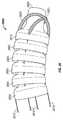
- FIG. 28shows the distal end 2800 of an embodiment of a rigidizable cannula system similar to the cannula system 2500 of FIG. 25 .
- a tensioning element 2815 and a tensioning element 2816traverse nested links 2805 , wiper link 2810 and distal recirculating guides 2820 and 2821 .
- Wiper link 2810has a distal aperture 2825 that is narrower than that of the nested links 2805 .
- the narrow aperture 2825 of the wiper link 2810provides a close tolerance clearance for an inserted instrument that helps prevent the induction of material into the gap between the wiper link 2810 and an inserted instrument.
- the narrow aperturealso provides better direction control over the tip of an inserted instrument as it is advanced.
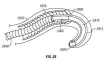
- FIG. 29shows an inner rigidizable linkage 2940 providing a conduit for an endoscope 2905 with a steerable tip 2910 coupled an endoscope tip liner 2915 by a gasket 2920 .
- the endoscope tip liner 2915provides a surface that allows the endoscope tip 2915 to slide freely within an outer rigidizable linkage 2935 .
- the endoscope tip liner 2915is constructed from helical mesh.
- the endoscope tip linermay be sized so that it fits within and fills a gap between a wiper link 2930 and the endoscope 2905 .
- the gasket 2920may also couple an external cover 2925 to the steerable tip 2910 .
- FIG. 30Ashows an embodiment of a cannula system 3000 having an endoscope 3001 coupled to handles 3002 and 3010 that serve as support for two independent actuating systems.
- Handle 3010supports static plate 3011 that is similar to static tension anchor 2505 of FIG. 25 .
- Dynamic plate 3012is similar to dynamic tension anchor 2515 of FIG. 25 , and is coupled to static plate 3011 by actuators 3013 and 3014 (e.g., air cylinders).
- Dynamic plate 3012is coupled to, and serves to compress an outer linkage 3020 that runs concentrically over rigidizable linkage 3015 .
- Actuators 3013 and 3014serve to axially separate static plate 3011 and dynamic plate 3012 , thus providing the operation as described with respect to FIG. 25 .
- Handle 3002supports static plate 3004 , which is in turn coupled to dynamic plate 3003 by actuators 3005 and 3006 (e.g., air cylinders). Actuators 3005 and 3006 serve to axially separate static plate 3004 and dynamic plate 3003 , thus providing the operation as described with respect to FIG. 25 .
- a cannula 3008 that includes a rigidizable linkage 3015 similar to 2520 of FIG. 25is attached to dynamic plate 3003 .
- FIG. 30Bshows the cannula system 3000 of FIG. 30A in a retracted configuration.
- Handle 3003has been displaced with respect to handle 3010 so that a greater portion of the rigidizable linkage 3015 resides within outer linkage 3020 .
- FIG. 31Ashows an embodiment of a cannula system 3100 .
- a reference frame handle 3105supports a static anchor plate 3125 that is coupled to actuators 3110 and 3115 (e.g., air cylinders).
- a rigidizable linkage 3130is coupled to dynamic anchor plate 3120 .
- Cannula system 3100is similar to system 2500 of FIG. 25 .
- Actuators 3110 and 3115are inactive and the rigidizable linkage 3130 is in a relaxed state.
- FIG. 31Bshows the cannula system 3100 of FIG. 31A in a rigidized configuration. Actuators 3110 and 3115 are active, and the separation between static anchor plate 3125 and dynamic anchor plate 3120 is increased, thereby rigidizing the rigidizable linkage 3130 .
- the reference frame handle 3105allows a user to establish the relative position of the endoscope 3101 and the rigidizable linkage 3130 to expose a length L 1 of the tip of the endoscope 3101 .
- L 2is the distance from the tip of the rigidizable linkage 3130 to the handle.
- L 2is essentially constant, whether the rigidizable linkage 3130 is in a relaxed or rigidized state.
- the rigidizable linkage 3130may be rigidized without substantially altering L 2 , while essentially maintaining the exposed tip length L 1 without having to adjust the position of endoscope 3101 during the rigidization process.
- FIG. 32depicts a flow diagram of a method for rigidizing a cannula system in conjunction with an endoscope.
- an endoscopeis axially displaced with respect to a surrounding rigidizable cannula to expose a specific length of a tip of the endoscope.
- a relative position between a handle of the cannula system and the endoscopeis established.
- actuatorsare activated to rigidize a cannula while maintaining the previously established exposed length of the endoscope tip and relative position between the handle of the cannula system and the endoscope.
- FIG. 33Ashows an embodiment of a cannula system 3300 similar to that shown in FIG. 31A .
- a handle 3305is coupled to a rigidizable linkage 3310 that acts as a conduit for an endoscope 3301 .
- An inflatable balloon 3315is coupled to the distal tip of rigidizable linkage 3310 . While linkage 3310 is rigidized to support advancement of the endoscope 3301 , the balloon 3315 may be inflated such that it engages a lumen, especially in mobile tissue such as the small bowel, so as to locally immobilize it such that endoscope 3301 may advance through the lumen efficiently. Balloon 3315 may then be deflated to advance linkage 3310 along endoscope 3301 . Alternately, balloon 3315 may be used to hold the position of linkage 3310 relative to mobile tissue when linkage 3310 is relaxed for repositioning (e.g. for scope “straightening”).
- FIG. 33Bshows an embodiment of a cannula system 3302 that is similar to the cannula system 3300 shown in FIG. 33A , but whose rigidizable linkage 3330 serves as a conduit for endoscope 3320 that includes an inflatable balloon 3345 .
- a balloon 3335is coupled to the distal tip of the rigidizable linkage 3330 and a balloon 3345 is coupled to the endoscope 3320 proximal to the steering tip 3340 .
- Balloon 3345may be inflated to engage a lumen and hold position of mobile tissue such as the small bowel while the rigidizable linkage 3330 is made flexible and advanced over the endoscope 3320 .
Landscapes
- Health & Medical Sciences (AREA)
- Life Sciences & Earth Sciences (AREA)
- Engineering & Computer Science (AREA)
- Biomedical Technology (AREA)
- Pulmonology (AREA)
- Anesthesiology (AREA)
- Biophysics (AREA)
- Heart & Thoracic Surgery (AREA)
- Hematology (AREA)
- Animal Behavior & Ethology (AREA)
- General Health & Medical Sciences (AREA)
- Public Health (AREA)
- Veterinary Medicine (AREA)
- Mechanical Engineering (AREA)
- Surgical Instruments (AREA)
Abstract
Description
Claims (14)
Priority Applications (3)
| Application Number | Priority Date | Filing Date | Title |
|---|---|---|---|
| US11/479,704US7947000B2 (en) | 2003-09-12 | 2006-06-30 | Cannula system for free-space navigation and method of use |
| US13/087,156US9808597B2 (en) | 2002-09-12 | 2011-04-14 | Shape-transferring cannula system and method of use |
| US15/701,417US20180064904A1 (en) | 2002-09-12 | 2017-09-11 | Shape-transferring cannula system and method of use |
Applications Claiming Priority (2)
| Application Number | Priority Date | Filing Date | Title |
|---|---|---|---|
| US10/661,159US8298161B2 (en) | 2002-09-12 | 2003-09-12 | Shape-transferring cannula system and method of use |
| US11/479,704US7947000B2 (en) | 2003-09-12 | 2006-06-30 | Cannula system for free-space navigation and method of use |
Related Parent Applications (1)
| Application Number | Title | Priority Date | Filing Date |
|---|---|---|---|
| US10/661,159Continuation-In-PartUS8298161B2 (en) | 2002-09-12 | 2003-09-12 | Shape-transferring cannula system and method of use |
Related Child Applications (2)
| Application Number | Title | Priority Date | Filing Date |
|---|---|---|---|
| US13/087,156Continuation-In-PartUS9808597B2 (en) | 2002-09-12 | 2011-04-14 | Shape-transferring cannula system and method of use |
| US13/087,156ContinuationUS9808597B2 (en) | 2002-09-12 | 2011-04-14 | Shape-transferring cannula system and method of use |
Publications (2)
| Publication Number | Publication Date |
|---|---|
| US20080091170A1 US20080091170A1 (en) | 2008-04-17 |
| US7947000B2true US7947000B2 (en) | 2011-05-24 |
Family
ID=39303933
Family Applications (1)
| Application Number | Title | Priority Date | Filing Date |
|---|---|---|---|
| US11/479,704Expired - LifetimeUS7947000B2 (en) | 2002-09-12 | 2006-06-30 | Cannula system for free-space navigation and method of use |
Country Status (1)
| Country | Link |
|---|---|
| US (1) | US7947000B2 (en) |
Cited By (91)
| Publication number | Priority date | Publication date | Assignee | Title |
|---|---|---|---|---|
| US20080287739A1 (en)* | 2007-05-18 | 2008-11-20 | Syntheon Llc | Torque-Transmitting, Locking Instrument Holder and Method for Operating the Instrument Holder |
| US20100036392A1 (en)* | 2006-05-05 | 2010-02-11 | Zoran Milijasevic | Modular catheter assembly |
| US20100137955A1 (en)* | 2006-08-04 | 2010-06-03 | Cathrx Ltd. | Catheter handle assembly |
| US20100152537A1 (en)* | 2008-12-17 | 2010-06-17 | Eiichi Kobayashi | Guide tube, guide tube apparatus, endoscope system, and method for self-propelling guide tube |
| US20110253865A1 (en)* | 2006-10-20 | 2011-10-20 | Carnegie Mellon University | Apparatus for positioning a device |
| US8070759B2 (en) | 2008-05-30 | 2011-12-06 | Ethicon Endo-Surgery, Inc. | Surgical fastening device |
| US8075572B2 (en) | 2007-04-26 | 2011-12-13 | Ethicon Endo-Surgery, Inc. | Surgical suturing apparatus |
| US8114119B2 (en) | 2008-09-09 | 2012-02-14 | Ethicon Endo-Surgery, Inc. | Surgical grasping device |
| US8114072B2 (en) | 2008-05-30 | 2012-02-14 | Ethicon Endo-Surgery, Inc. | Electrical ablation device |
| US8157834B2 (en) | 2008-11-25 | 2012-04-17 | Ethicon Endo-Surgery, Inc. | Rotational coupling device for surgical instrument with flexible actuators |
| US8172772B2 (en) | 2008-12-11 | 2012-05-08 | Ethicon Endo-Surgery, Inc. | Specimen retrieval device |
| US8211125B2 (en) | 2008-08-15 | 2012-07-03 | Ethicon Endo-Surgery, Inc. | Sterile appliance delivery device for endoscopic procedures |
| US8241204B2 (en) | 2008-08-29 | 2012-08-14 | Ethicon Endo-Surgery, Inc. | Articulating end cap |
| US8252057B2 (en) | 2009-01-30 | 2012-08-28 | Ethicon Endo-Surgery, Inc. | Surgical access device |
| US8262563B2 (en) | 2008-07-14 | 2012-09-11 | Ethicon Endo-Surgery, Inc. | Endoscopic translumenal articulatable steerable overtube |
| US8262680B2 (en) | 2008-03-10 | 2012-09-11 | Ethicon Endo-Surgery, Inc. | Anastomotic device |
| US8262655B2 (en) | 2007-11-21 | 2012-09-11 | Ethicon Endo-Surgery, Inc. | Bipolar forceps |
| US8317806B2 (en) | 2008-05-30 | 2012-11-27 | Ethicon Endo-Surgery, Inc. | Endoscopic suturing tension controlling and indication devices |
| US8337394B2 (en) | 2008-10-01 | 2012-12-25 | Ethicon Endo-Surgery, Inc. | Overtube with expandable tip |
| US8353487B2 (en) | 2009-12-17 | 2013-01-15 | Ethicon Endo-Surgery, Inc. | User interface support devices for endoscopic surgical instruments |
| US8361112B2 (en) | 2008-06-27 | 2013-01-29 | Ethicon Endo-Surgery, Inc. | Surgical suture arrangement |
| US8403926B2 (en) | 2008-06-05 | 2013-03-26 | Ethicon Endo-Surgery, Inc. | Manually articulating devices |
| US8409200B2 (en) | 2008-09-03 | 2013-04-02 | Ethicon Endo-Surgery, Inc. | Surgical grasping device |
| US20130096377A1 (en)* | 2011-10-14 | 2013-04-18 | Intuitive Surgical Operations, Inc. | Catheter with removable vision probe |
| US8425505B2 (en) | 2007-02-15 | 2013-04-23 | Ethicon Endo-Surgery, Inc. | Electroporation ablation apparatus, system, and method |
| US8480657B2 (en) | 2007-10-31 | 2013-07-09 | Ethicon Endo-Surgery, Inc. | Detachable distal overtube section and methods for forming a sealable opening in the wall of an organ |
| US8480689B2 (en) | 2008-09-02 | 2013-07-09 | Ethicon Endo-Surgery, Inc. | Suturing device |
| US8496574B2 (en) | 2009-12-17 | 2013-07-30 | Ethicon Endo-Surgery, Inc. | Selectively positionable camera for surgical guide tube assembly |
| US8506564B2 (en) | 2009-12-18 | 2013-08-13 | Ethicon Endo-Surgery, Inc. | Surgical instrument comprising an electrode |
| US8529563B2 (en) | 2008-08-25 | 2013-09-10 | Ethicon Endo-Surgery, Inc. | Electrical ablation devices |
| US8568410B2 (en) | 2007-08-31 | 2013-10-29 | Ethicon Endo-Surgery, Inc. | Electrical ablation surgical instruments |
| US8579897B2 (en) | 2007-11-21 | 2013-11-12 | Ethicon Endo-Surgery, Inc. | Bipolar forceps |
| US8608652B2 (en) | 2009-11-05 | 2013-12-17 | Ethicon Endo-Surgery, Inc. | Vaginal entry surgical devices, kit, system, and method |
| US8652150B2 (en) | 2008-05-30 | 2014-02-18 | Ethicon Endo-Surgery, Inc. | Multifunction surgical device |
| US8679003B2 (en) | 2008-05-30 | 2014-03-25 | Ethicon Endo-Surgery, Inc. | Surgical device and endoscope including same |
| US8771260B2 (en) | 2008-05-30 | 2014-07-08 | Ethicon Endo-Surgery, Inc. | Actuating and articulating surgical device |
| US8828031B2 (en) | 2009-01-12 | 2014-09-09 | Ethicon Endo-Surgery, Inc. | Apparatus for forming an anastomosis |
| US8888792B2 (en) | 2008-07-14 | 2014-11-18 | Ethicon Endo-Surgery, Inc. | Tissue apposition clip application devices and methods |
| US8906035B2 (en) | 2008-06-04 | 2014-12-09 | Ethicon Endo-Surgery, Inc. | Endoscopic drop off bag |
| US8939897B2 (en) | 2007-10-31 | 2015-01-27 | Ethicon Endo-Surgery, Inc. | Methods for closing a gastrotomy |
| US8986199B2 (en) | 2012-02-17 | 2015-03-24 | Ethicon Endo-Surgery, Inc. | Apparatus and methods for cleaning the lens of an endoscope |
| US9005198B2 (en) | 2010-01-29 | 2015-04-14 | Ethicon Endo-Surgery, Inc. | Surgical instrument comprising an electrode |
| US9011431B2 (en) | 2009-01-12 | 2015-04-21 | Ethicon Endo-Surgery, Inc. | Electrical ablation devices |
| US9028483B2 (en) | 2009-12-18 | 2015-05-12 | Ethicon Endo-Surgery, Inc. | Surgical instrument comprising an electrode |
| US9049987B2 (en) | 2011-03-17 | 2015-06-09 | Ethicon Endo-Surgery, Inc. | Hand held surgical device for manipulating an internal magnet assembly within a patient |
| US9078662B2 (en) | 2012-07-03 | 2015-07-14 | Ethicon Endo-Surgery, Inc. | Endoscopic cap electrode and method for using the same |
| US9226772B2 (en) | 2009-01-30 | 2016-01-05 | Ethicon Endo-Surgery, Inc. | Surgical device |
| US9233241B2 (en) | 2011-02-28 | 2016-01-12 | Ethicon Endo-Surgery, Inc. | Electrical ablation devices and methods |
| US9254169B2 (en) | 2011-02-28 | 2016-02-09 | Ethicon Endo-Surgery, Inc. | Electrical ablation devices and methods |
| US9277957B2 (en) | 2012-08-15 | 2016-03-08 | Ethicon Endo-Surgery, Inc. | Electrosurgical devices and methods |
| US9314620B2 (en) | 2011-02-28 | 2016-04-19 | Ethicon Endo-Surgery, Inc. | Electrical ablation devices and methods |
| US9387048B2 (en) | 2011-10-14 | 2016-07-12 | Intuitive Surgical Operations, Inc. | Catheter sensor systems |
| US9427255B2 (en) | 2012-05-14 | 2016-08-30 | Ethicon Endo-Surgery, Inc. | Apparatus for introducing a steerable camera assembly into a patient |
| US9439693B2 (en) | 2013-02-01 | 2016-09-13 | DePuy Synthes Products, Inc. | Steerable needle assembly for use in vertebral body augmentation |
| US9545290B2 (en) | 2012-07-30 | 2017-01-17 | Ethicon Endo-Surgery, Inc. | Needle probe guide |
| US9572623B2 (en) | 2012-08-02 | 2017-02-21 | Ethicon Endo-Surgery, Inc. | Reusable electrode and disposable sheath |
| US9610083B2 (en)* | 2011-08-09 | 2017-04-04 | DePuy Synthes Products, Inc. | Articulated cavity creator |
| US9808597B2 (en) | 2002-09-12 | 2017-11-07 | Intuitive Surgical Operations, Inc. | Shape-transferring cannula system and method of use |
| WO2017200991A3 (en)* | 2016-05-16 | 2017-12-28 | President And Fellows Of Harvard College | Soft actuators for pop-up laminate structures |
| US20180064908A1 (en)* | 2015-03-26 | 2018-03-08 | SPIRATION, INC., d/b/a OLYMPUS RESPIRATORY AMERICA | Variable stiffness medical device |
| US10092291B2 (en) | 2011-01-25 | 2018-10-09 | Ethicon Endo-Surgery, Inc. | Surgical instrument with selectively rigidizable features |
| US10098527B2 (en) | 2013-02-27 | 2018-10-16 | Ethidcon Endo-Surgery, Inc. | System for performing a minimally invasive surgical procedure |
| US10143362B2 (en) | 2002-09-12 | 2018-12-04 | Intuitive Surgical Operations, Inc. | Shape-transferring cannula system and method of use |
| WO2019018682A1 (en)* | 2017-07-20 | 2019-01-24 | Neptune Medical Inc. | Dynamically rigidizing overtube |
| US10238837B2 (en) | 2011-10-14 | 2019-03-26 | Intuitive Surgical Operations, Inc. | Catheters with control modes for interchangeable probes |
| US10299812B2 (en) | 2015-06-05 | 2019-05-28 | Cook Medical Technologies Llc | Medical device snare |
| US10314649B2 (en) | 2012-08-02 | 2019-06-11 | Ethicon Endo-Surgery, Inc. | Flexible expandable electrode and method of intraluminal delivery of pulsed power |
| US10682070B2 (en) | 2011-10-14 | 2020-06-16 | Intuitive Surgical Operations, Inc. | Electromagnetic sensor with probe and guide sensing elements |
| US10779882B2 (en) | 2009-10-28 | 2020-09-22 | Ethicon Endo-Surgery, Inc. | Electrical ablation devices |
| US11122971B2 (en) | 2016-08-18 | 2021-09-21 | Neptune Medical Inc. | Device and method for enhanced visualization of the small intestine |
| US11135398B2 (en) | 2018-07-19 | 2021-10-05 | Neptune Medical Inc. | Dynamically rigidizing composite medical structures |
| US11219351B2 (en) | 2015-09-03 | 2022-01-11 | Neptune Medical Inc. | Device for endoscopic advancement through the small intestine |
| US11282251B2 (en) | 2018-05-02 | 2022-03-22 | Covidien Lp | System and method for constructing virtual radial ultrasound images from CT data and performing a surgical navigation procedure using virtual ultrasound images |
| US11529190B2 (en) | 2017-01-30 | 2022-12-20 | Covidien Lp | Enhanced ablation and visualization techniques for percutaneous surgical procedures |
| US11701179B2 (en) | 2018-07-26 | 2023-07-18 | Covidien Lp | Modeling a collapsed lung using CT data |
| US11701492B2 (en) | 2020-06-04 | 2023-07-18 | Covidien Lp | Active distal tip drive |
| US11744443B2 (en) | 2020-03-30 | 2023-09-05 | Neptune Medical Inc. | Layered walls for rigidizing devices |
| US11793392B2 (en) | 2019-04-17 | 2023-10-24 | Neptune Medical Inc. | External working channels |
| US11918338B2 (en) | 2015-09-23 | 2024-03-05 | Coviden Lp | Elongated catheter having sensor and an extended working channel |
| US11937778B2 (en) | 2022-04-27 | 2024-03-26 | Neptune Medical Inc. | Apparatuses and methods for determining if an endoscope is contaminated |
| US11975157B2 (en) | 2019-04-12 | 2024-05-07 | Covidien Lp | Method of manufacturing an elongated catheter having multiple sensors for three-dimensional location of the catheter |
| US12059128B2 (en) | 2018-05-31 | 2024-08-13 | Neptune Medical Inc. | Device and method for enhanced visualization of the small intestine |
| US12064191B2 (en) | 2020-06-03 | 2024-08-20 | Covidien Lp | Surgical tool navigation using sensor fusion |
| US12121677B2 (en) | 2021-01-29 | 2024-10-22 | Neptune Medical Inc. | Devices and methods to prevent inadvertent motion of dynamically rigidizing apparatuses |
| US12161309B2 (en) | 2020-09-24 | 2024-12-10 | Covidien Lp | Articulating mechanism for the laparoscopic ablation device for blunt dissection |
| US12185974B2 (en) | 2019-10-17 | 2025-01-07 | Intuitive Surgical Operations, Inc. | Surgical tool with nested shaft tubes |
| US12256923B2 (en) | 2020-08-13 | 2025-03-25 | Covidien Lp | Endoluminal robotic systems and methods for suturing |
| US12303220B2 (en) | 2022-01-26 | 2025-05-20 | Covidien Lp | Autonomous endobronchial access with an EM guided catheter |
| US12329473B2 (en) | 2019-04-17 | 2025-06-17 | Neptune Medical Inc. | Dynamically rigidizing composite medical structures |
| US12330292B2 (en) | 2023-09-28 | 2025-06-17 | Neptune Medical Inc. | Telescoping robot |
| US12383352B2 (en) | 2020-08-13 | 2025-08-12 | Covidien Lp | Endoluminal robotic (ELR) systems and methods |
Families Citing this family (45)
| Publication number | Priority date | Publication date | Assignee | Title |
|---|---|---|---|---|
| CH696424A5 (en)* | 2002-10-15 | 2007-06-15 | Alexander Von Weymarn Schaerli | Guide device, in particular for positioning catheters in a body passage. |
| US7771411B2 (en) | 2004-09-24 | 2010-08-10 | Syntheon, Llc | Methods for operating a selective stiffening catheter |
| US7930065B2 (en) | 2005-12-30 | 2011-04-19 | Intuitive Surgical Operations, Inc. | Robotic surgery system including position sensors using fiber bragg gratings |
| US9962066B2 (en) | 2005-12-30 | 2018-05-08 | Intuitive Surgical Operations, Inc. | Methods and apparatus to shape flexible entry guides for minimally invasive surgery |
| US8092374B2 (en) | 2006-03-02 | 2012-01-10 | Kevin Smith | Variably flexible insertion device and method for variably flexing an insertion device |
| US9814372B2 (en)* | 2007-06-27 | 2017-11-14 | Syntheon, Llc | Torque-transmitting, variably-flexible, locking insertion device and method for operating the insertion device |
| US7988621B2 (en)* | 2006-08-10 | 2011-08-02 | Syntheon, Llc | Torque-transmitting, variably-flexible, corrugated insertion device and method for transmitting torque and variably flexing a corrugated insertion device |
| US9155451B2 (en) | 2006-03-02 | 2015-10-13 | Syntheon, Llc | Variably flexible insertion device and method for variably flexing an insertion device |
| US10123683B2 (en) | 2006-03-02 | 2018-11-13 | Syntheon, Llc | Variably flexible insertion device and method for variably flexing an insertion device |
| CA2650474A1 (en) | 2006-04-24 | 2007-11-08 | Synecor, Llc | Natural orifice surgical system |
| US8518024B2 (en)* | 2006-04-24 | 2013-08-27 | Transenterix, Inc. | System and method for multi-instrument surgical access using a single access port |
| KR101477133B1 (en) | 2006-06-13 | 2014-12-29 | 인튜어티브 서지컬 인코포레이티드 | Minimally invasive surgical system |
| US9096033B2 (en) | 2007-06-13 | 2015-08-04 | Intuitive Surgical Operations, Inc. | Surgical system instrument sterile adapter |
| US20110060183A1 (en)* | 2007-09-12 | 2011-03-10 | Salvatore Castro | Multi-instrument access devices and systems |
| WO2009035663A2 (en)* | 2007-09-12 | 2009-03-19 | Synecor, Llc | Multi-instrument access devices and systems |
| US8172189B2 (en)* | 2007-09-18 | 2012-05-08 | Civco Medical Instruments Co., Inc. | Device for precision positioning of instruments at a MRI scanner |
| US20090228020A1 (en)* | 2008-03-06 | 2009-09-10 | Hansen Medical, Inc. | In-situ graft fenestration |
| US8496648B2 (en)* | 2008-05-27 | 2013-07-30 | Intuitive Surgical Operations, Inc. | Stiffening assembly |
| CN104887170B (en) | 2008-09-05 | 2017-06-09 | 卡内基梅隆大学 | More piece endoscopic apparatus with spherical distal ends component |
| WO2011007351A1 (en)* | 2009-07-13 | 2011-01-20 | Fund For Medical Research - Rambam Medical Center | Surgical stapler assembly |
| US20110184231A1 (en)* | 2009-07-28 | 2011-07-28 | Page Brett M | Deflectable instrument ports |
| US20110071541A1 (en) | 2009-09-23 | 2011-03-24 | Intuitive Surgical, Inc. | Curved cannula |
| WO2011060031A1 (en) | 2009-09-23 | 2011-05-19 | Intuitive Surgical Operations, Inc. | Curved cannula surgical system |
| US8545515B2 (en) | 2009-09-23 | 2013-10-01 | Intuitive Surgical Operations, Inc. | Curved cannula surgical system |
| US8623028B2 (en) | 2009-09-23 | 2014-01-07 | Intuitive Surgical Operations, Inc. | Surgical port feature |
| US8888789B2 (en) | 2009-09-23 | 2014-11-18 | Intuitive Surgical Operations, Inc. | Curved cannula surgical system control |
| US8465476B2 (en) | 2009-09-23 | 2013-06-18 | Intuitive Surgical Operations, Inc. | Cannula mounting fixture |
| US20110308835A1 (en)* | 2010-06-16 | 2011-12-22 | Piekny Mark G | Self-coiling apparatus |
| CN102770061B (en)* | 2010-09-30 | 2014-11-12 | 奥林巴斯医疗株式会社 | Insertion aid, and endoscope device |
| US9055960B2 (en) | 2010-11-15 | 2015-06-16 | Intuitive Surgical Operations, Inc. | Flexible surgical devices |
| US20120277757A1 (en)* | 2011-04-13 | 2012-11-01 | Curax, Llc | Multi-function cannulated surgical device |
| US9283019B2 (en) | 2011-06-08 | 2016-03-15 | Warsaw Orthopedic, Inc. | Flexible guide wire |
| WO2013067582A1 (en) | 2011-11-08 | 2013-05-16 | Resmed Limited | Electrically stimulated respiratory assistance components |
| US9901707B2 (en)* | 2012-05-23 | 2018-02-27 | Integra Lifesciences Switzerland Sàrl | Catheter curvature braces and methods of using same |
| US20140142497A1 (en)* | 2012-08-13 | 2014-05-22 | Michael Esposito | Bowed tip for laparoscopic surgery |
| US10383648B2 (en) | 2013-02-17 | 2019-08-20 | Human Extensions Ltd. | Steerable medical device |
| WO2015077584A2 (en) | 2013-11-22 | 2015-05-28 | Massachusetts Institute Of Technology | Steering techniques for surgical instruments |
| WO2016076964A2 (en)* | 2014-09-30 | 2016-05-19 | Massachusetts Institute Of Technology | Instruments for minimally invasive surgical procedures |
| JP7252894B2 (en)* | 2017-02-28 | 2023-04-05 | ボストン サイエンティフィック サイムド,インコーポレイテッド | articulating needle |
| US10751507B2 (en) | 2017-04-10 | 2020-08-25 | Syn Variflex, Llc | Thermally controlled variable-flexibility catheters and methods of manufacturing same |
| CN107789100B (en)* | 2017-12-08 | 2024-04-12 | 河北瑞鹤医疗器械有限公司 | Fusion device pusher |
| US11717322B2 (en) | 2020-08-17 | 2023-08-08 | Covidien Lp | Flexible cannula having selective rigidity |
| CN112957590B (en)* | 2020-12-31 | 2022-09-27 | 杭州德诺电生理医疗科技有限公司 | Ablation system, ablation device and bendable catheter |
| CN119255741A (en)* | 2022-03-25 | 2025-01-03 | 海王星医疗公司 | Method and apparatus for navigation using a pair of rigidified devices |
| CN119998001A (en)* | 2022-10-07 | 2025-05-13 | 苏黎世联邦理工学院 | Steerable device for use in mammals |
Citations (16)
| Publication number | Priority date | Publication date | Assignee | Title |
|---|---|---|---|---|
| US616672A (en) | 1898-12-27 | kelling | ||
| US2421279A (en) | 1943-03-25 | 1947-05-27 | Emanuel Merian | Body with movable parts |
| US3096962A (en) | 1960-02-04 | 1963-07-09 | Meijs Pieter Johannes | Locking device for a measuring apparatus or the like |
| US5251611A (en)* | 1991-05-07 | 1993-10-12 | Zehel Wendell E | Method and apparatus for conducting exploratory procedures |
| US5482029A (en) | 1992-06-26 | 1996-01-09 | Kabushiki Kaisha Toshiba | Variable flexibility endoscope system |
| US5681260A (en) | 1989-09-22 | 1997-10-28 | Olympus Optical Co., Ltd. | Guiding apparatus for guiding an insertable body within an inspected object |
| US5766163A (en) | 1996-07-03 | 1998-06-16 | Eclipse Surgical Technologies, Inc. | Controllable trocar for transmyocardial revascularization (TMR) via endocardium method and apparatus |
| US5820163A (en) | 1996-07-08 | 1998-10-13 | Ford Global Technologies, Inc. | Tilting, telescoping and energy absorbing steering column |
| US5911714A (en) | 1994-02-23 | 1999-06-15 | Mitek Surgical Products, Inc. | Surgical cannula system |
| US5921915A (en) | 1997-04-30 | 1999-07-13 | C.R. Bard, Inc. | Directional surgical device for use with endoscope, gastroscope, colonoscope or the like |
| US5976146A (en) | 1997-07-11 | 1999-11-02 | Olympus Optical Co., Ltd. | Surgical operation system and method of securing working space for surgical operation in body |
| US5976074A (en) | 1995-09-29 | 1999-11-02 | Olympus Optical Co., Ltd. | Endoscope provided with function of being locked to flexibility of insertion part which is set by flexibility modifying operation member |
| US6007519A (en) | 1997-07-30 | 1999-12-28 | Rosselli; Matteo | Central access cannulation device |
| US6071234A (en) | 1998-06-03 | 2000-06-06 | Takada; Masazumi | Self-propelled colonoscope |
| US6206872B1 (en) | 1996-06-24 | 2001-03-27 | Karl Storz Gmbh & Co. Kg | Endoscopic instrument which can be bent |
| US6581889B2 (en)* | 2000-01-10 | 2003-06-24 | Medivas, Llc | Flexible stabilizer arm for forcibly holding an object against a surface |
- 2006
- 2006-06-30USUS11/479,704patent/US7947000B2/ennot_activeExpired - Lifetime
Patent Citations (16)
| Publication number | Priority date | Publication date | Assignee | Title |
|---|---|---|---|---|
| US616672A (en) | 1898-12-27 | kelling | ||
| US2421279A (en) | 1943-03-25 | 1947-05-27 | Emanuel Merian | Body with movable parts |
| US3096962A (en) | 1960-02-04 | 1963-07-09 | Meijs Pieter Johannes | Locking device for a measuring apparatus or the like |
| US5681260A (en) | 1989-09-22 | 1997-10-28 | Olympus Optical Co., Ltd. | Guiding apparatus for guiding an insertable body within an inspected object |
| US5251611A (en)* | 1991-05-07 | 1993-10-12 | Zehel Wendell E | Method and apparatus for conducting exploratory procedures |
| US5482029A (en) | 1992-06-26 | 1996-01-09 | Kabushiki Kaisha Toshiba | Variable flexibility endoscope system |
| US5911714A (en) | 1994-02-23 | 1999-06-15 | Mitek Surgical Products, Inc. | Surgical cannula system |
| US5976074A (en) | 1995-09-29 | 1999-11-02 | Olympus Optical Co., Ltd. | Endoscope provided with function of being locked to flexibility of insertion part which is set by flexibility modifying operation member |
| US6206872B1 (en) | 1996-06-24 | 2001-03-27 | Karl Storz Gmbh & Co. Kg | Endoscopic instrument which can be bent |
| US5766163A (en) | 1996-07-03 | 1998-06-16 | Eclipse Surgical Technologies, Inc. | Controllable trocar for transmyocardial revascularization (TMR) via endocardium method and apparatus |
| US5820163A (en) | 1996-07-08 | 1998-10-13 | Ford Global Technologies, Inc. | Tilting, telescoping and energy absorbing steering column |
| US5921915A (en) | 1997-04-30 | 1999-07-13 | C.R. Bard, Inc. | Directional surgical device for use with endoscope, gastroscope, colonoscope or the like |
| US5976146A (en) | 1997-07-11 | 1999-11-02 | Olympus Optical Co., Ltd. | Surgical operation system and method of securing working space for surgical operation in body |
| US6007519A (en) | 1997-07-30 | 1999-12-28 | Rosselli; Matteo | Central access cannulation device |
| US6071234A (en) | 1998-06-03 | 2000-06-06 | Takada; Masazumi | Self-propelled colonoscope |
| US6581889B2 (en)* | 2000-01-10 | 2003-06-24 | Medivas, Llc | Flexible stabilizer arm for forcibly holding an object against a surface |
Cited By (145)
| Publication number | Priority date | Publication date | Assignee | Title |
|---|---|---|---|---|
| US10143362B2 (en) | 2002-09-12 | 2018-12-04 | Intuitive Surgical Operations, Inc. | Shape-transferring cannula system and method of use |
| US9808597B2 (en) | 2002-09-12 | 2017-11-07 | Intuitive Surgical Operations, Inc. | Shape-transferring cannula system and method of use |
| US11395580B2 (en) | 2002-09-12 | 2022-07-26 | Intuitive Surgical Operations, Inc. | Shape-transferring cannula system and method of use |
| US10314465B2 (en) | 2002-09-12 | 2019-06-11 | Intuitive Surgical Operations, Inc. | Shape-transferring cannula system and method of use |
| US9642982B2 (en) | 2006-05-05 | 2017-05-09 | Cathrx Ltd. | Modular catheter assembly |
| US20100036392A1 (en)* | 2006-05-05 | 2010-02-11 | Zoran Milijasevic | Modular catheter assembly |
| US9008795B2 (en)* | 2006-08-04 | 2015-04-14 | Cathrx Ltd | Catheter handle assembly |
| US20100137955A1 (en)* | 2006-08-04 | 2010-06-03 | Cathrx Ltd. | Catheter handle assembly |
| US20110253865A1 (en)* | 2006-10-20 | 2011-10-20 | Carnegie Mellon University | Apparatus for positioning a device |
| US8919710B2 (en) | 2006-10-20 | 2014-12-30 | Carnegie Mellon University | Apparatus for positioning a device |
| US8444096B2 (en)* | 2006-10-20 | 2013-05-21 | Carnegie Mellon University | Apparatus for positioning a device |
| US8449538B2 (en) | 2007-02-15 | 2013-05-28 | Ethicon Endo-Surgery, Inc. | Electroporation ablation apparatus, system, and method |
| US9375268B2 (en) | 2007-02-15 | 2016-06-28 | Ethicon Endo-Surgery, Inc. | Electroporation ablation apparatus, system, and method |
| US10478248B2 (en) | 2007-02-15 | 2019-11-19 | Ethicon Llc | Electroporation ablation apparatus, system, and method |
| US8425505B2 (en) | 2007-02-15 | 2013-04-23 | Ethicon Endo-Surgery, Inc. | Electroporation ablation apparatus, system, and method |
| US8075572B2 (en) | 2007-04-26 | 2011-12-13 | Ethicon Endo-Surgery, Inc. | Surgical suturing apparatus |
| US20080287739A1 (en)* | 2007-05-18 | 2008-11-20 | Syntheon Llc | Torque-Transmitting, Locking Instrument Holder and Method for Operating the Instrument Holder |
| US9707376B2 (en)* | 2007-05-18 | 2017-07-18 | Syntheon, Llc | Torque-transmitting, locking instrument holder and method for operating the instrument holder |
| US10004876B2 (en)* | 2007-05-18 | 2018-06-26 | Syntheon, Llc | Torque-transmitting, locking instrument holder and method for operating the instrument holder |
| US8568410B2 (en) | 2007-08-31 | 2013-10-29 | Ethicon Endo-Surgery, Inc. | Electrical ablation surgical instruments |
| US8939897B2 (en) | 2007-10-31 | 2015-01-27 | Ethicon Endo-Surgery, Inc. | Methods for closing a gastrotomy |
| US8480657B2 (en) | 2007-10-31 | 2013-07-09 | Ethicon Endo-Surgery, Inc. | Detachable distal overtube section and methods for forming a sealable opening in the wall of an organ |
| US8262655B2 (en) | 2007-11-21 | 2012-09-11 | Ethicon Endo-Surgery, Inc. | Bipolar forceps |
| US8579897B2 (en) | 2007-11-21 | 2013-11-12 | Ethicon Endo-Surgery, Inc. | Bipolar forceps |
| US8262680B2 (en) | 2008-03-10 | 2012-09-11 | Ethicon Endo-Surgery, Inc. | Anastomotic device |
| US8317806B2 (en) | 2008-05-30 | 2012-11-27 | Ethicon Endo-Surgery, Inc. | Endoscopic suturing tension controlling and indication devices |
| US8771260B2 (en) | 2008-05-30 | 2014-07-08 | Ethicon Endo-Surgery, Inc. | Actuating and articulating surgical device |
| US8114072B2 (en) | 2008-05-30 | 2012-02-14 | Ethicon Endo-Surgery, Inc. | Electrical ablation device |
| US8679003B2 (en) | 2008-05-30 | 2014-03-25 | Ethicon Endo-Surgery, Inc. | Surgical device and endoscope including same |
| US8070759B2 (en) | 2008-05-30 | 2011-12-06 | Ethicon Endo-Surgery, Inc. | Surgical fastening device |
| US8652150B2 (en) | 2008-05-30 | 2014-02-18 | Ethicon Endo-Surgery, Inc. | Multifunction surgical device |
| US8906035B2 (en) | 2008-06-04 | 2014-12-09 | Ethicon Endo-Surgery, Inc. | Endoscopic drop off bag |
| US8403926B2 (en) | 2008-06-05 | 2013-03-26 | Ethicon Endo-Surgery, Inc. | Manually articulating devices |
| US8361112B2 (en) | 2008-06-27 | 2013-01-29 | Ethicon Endo-Surgery, Inc. | Surgical suture arrangement |
| US8262563B2 (en) | 2008-07-14 | 2012-09-11 | Ethicon Endo-Surgery, Inc. | Endoscopic translumenal articulatable steerable overtube |
| US8888792B2 (en) | 2008-07-14 | 2014-11-18 | Ethicon Endo-Surgery, Inc. | Tissue apposition clip application devices and methods |
| US11399834B2 (en) | 2008-07-14 | 2022-08-02 | Cilag Gmbh International | Tissue apposition clip application methods |
| US10105141B2 (en) | 2008-07-14 | 2018-10-23 | Ethicon Endo-Surgery, Inc. | Tissue apposition clip application methods |
| US8211125B2 (en) | 2008-08-15 | 2012-07-03 | Ethicon Endo-Surgery, Inc. | Sterile appliance delivery device for endoscopic procedures |
| US8529563B2 (en) | 2008-08-25 | 2013-09-10 | Ethicon Endo-Surgery, Inc. | Electrical ablation devices |
| US8241204B2 (en) | 2008-08-29 | 2012-08-14 | Ethicon Endo-Surgery, Inc. | Articulating end cap |
| US8480689B2 (en) | 2008-09-02 | 2013-07-09 | Ethicon Endo-Surgery, Inc. | Suturing device |
| US8409200B2 (en) | 2008-09-03 | 2013-04-02 | Ethicon Endo-Surgery, Inc. | Surgical grasping device |
| US8114119B2 (en) | 2008-09-09 | 2012-02-14 | Ethicon Endo-Surgery, Inc. | Surgical grasping device |
| US8337394B2 (en) | 2008-10-01 | 2012-12-25 | Ethicon Endo-Surgery, Inc. | Overtube with expandable tip |
| US9220526B2 (en) | 2008-11-25 | 2015-12-29 | Ethicon Endo-Surgery, Inc. | Rotational coupling device for surgical instrument with flexible actuators |
| US10314603B2 (en) | 2008-11-25 | 2019-06-11 | Ethicon Llc | Rotational coupling device for surgical instrument with flexible actuators |
| US8157834B2 (en) | 2008-11-25 | 2012-04-17 | Ethicon Endo-Surgery, Inc. | Rotational coupling device for surgical instrument with flexible actuators |
| US8172772B2 (en) | 2008-12-11 | 2012-05-08 | Ethicon Endo-Surgery, Inc. | Specimen retrieval device |
| US20100152537A1 (en)* | 2008-12-17 | 2010-06-17 | Eiichi Kobayashi | Guide tube, guide tube apparatus, endoscope system, and method for self-propelling guide tube |
| US8491465B2 (en)* | 2008-12-17 | 2013-07-23 | Olympus Corporation | Guide tube, guide tube apparatus, endoscope system, and method for self-propelling guide tube |
| US10004558B2 (en) | 2009-01-12 | 2018-06-26 | Ethicon Endo-Surgery, Inc. | Electrical ablation devices |
| US8828031B2 (en) | 2009-01-12 | 2014-09-09 | Ethicon Endo-Surgery, Inc. | Apparatus for forming an anastomosis |
| US9011431B2 (en) | 2009-01-12 | 2015-04-21 | Ethicon Endo-Surgery, Inc. | Electrical ablation devices |
| US9226772B2 (en) | 2009-01-30 | 2016-01-05 | Ethicon Endo-Surgery, Inc. | Surgical device |
| US8252057B2 (en) | 2009-01-30 | 2012-08-28 | Ethicon Endo-Surgery, Inc. | Surgical access device |
| US10779882B2 (en) | 2009-10-28 | 2020-09-22 | Ethicon Endo-Surgery, Inc. | Electrical ablation devices |
| US8608652B2 (en) | 2009-11-05 | 2013-12-17 | Ethicon Endo-Surgery, Inc. | Vaginal entry surgical devices, kit, system, and method |
| US8496574B2 (en) | 2009-12-17 | 2013-07-30 | Ethicon Endo-Surgery, Inc. | Selectively positionable camera for surgical guide tube assembly |
| US8353487B2 (en) | 2009-12-17 | 2013-01-15 | Ethicon Endo-Surgery, Inc. | User interface support devices for endoscopic surgical instruments |
| US9028483B2 (en) | 2009-12-18 | 2015-05-12 | Ethicon Endo-Surgery, Inc. | Surgical instrument comprising an electrode |
| US10098691B2 (en) | 2009-12-18 | 2018-10-16 | Ethicon Endo-Surgery, Inc. | Surgical instrument comprising an electrode |
| US8506564B2 (en) | 2009-12-18 | 2013-08-13 | Ethicon Endo-Surgery, Inc. | Surgical instrument comprising an electrode |
| US9005198B2 (en) | 2010-01-29 | 2015-04-14 | Ethicon Endo-Surgery, Inc. | Surgical instrument comprising an electrode |
| US10092291B2 (en) | 2011-01-25 | 2018-10-09 | Ethicon Endo-Surgery, Inc. | Surgical instrument with selectively rigidizable features |
| US10258406B2 (en) | 2011-02-28 | 2019-04-16 | Ethicon Llc | Electrical ablation devices and methods |
| US10278761B2 (en) | 2011-02-28 | 2019-05-07 | Ethicon Llc | Electrical ablation devices and methods |
| US9314620B2 (en) | 2011-02-28 | 2016-04-19 | Ethicon Endo-Surgery, Inc. | Electrical ablation devices and methods |
| US9254169B2 (en) | 2011-02-28 | 2016-02-09 | Ethicon Endo-Surgery, Inc. | Electrical ablation devices and methods |
| US9233241B2 (en) | 2011-02-28 | 2016-01-12 | Ethicon Endo-Surgery, Inc. | Electrical ablation devices and methods |
| US9883910B2 (en) | 2011-03-17 | 2018-02-06 | Eticon Endo-Surgery, Inc. | Hand held surgical device for manipulating an internal magnet assembly within a patient |
| US9049987B2 (en) | 2011-03-17 | 2015-06-09 | Ethicon Endo-Surgery, Inc. | Hand held surgical device for manipulating an internal magnet assembly within a patient |
| US9610083B2 (en)* | 2011-08-09 | 2017-04-04 | DePuy Synthes Products, Inc. | Articulated cavity creator |
| US9452276B2 (en)* | 2011-10-14 | 2016-09-27 | Intuitive Surgical Operations, Inc. | Catheter with removable vision probe |
| US10238837B2 (en) | 2011-10-14 | 2019-03-26 | Intuitive Surgical Operations, Inc. | Catheters with control modes for interchangeable probes |
| US11918340B2 (en) | 2011-10-14 | 2024-03-05 | Intuitive Surgical Opeartions, Inc. | Electromagnetic sensor with probe and guide sensing elements |
| US10653866B2 (en) | 2011-10-14 | 2020-05-19 | Intuitive Surgical Operations, Inc. | Catheter with removable vision probe |
| US10682070B2 (en) | 2011-10-14 | 2020-06-16 | Intuitive Surgical Operations, Inc. | Electromagnetic sensor with probe and guide sensing elements |
| US12127797B2 (en) | 2011-10-14 | 2024-10-29 | Intuitive Surgical Operations, Inc. | Catheter sensor systems |
| US10568700B2 (en) | 2011-10-14 | 2020-02-25 | Intuitive Surgical Operations, Inc. | Catheter sensor systems |
| US12390618B2 (en)* | 2011-10-14 | 2025-08-19 | Intuitive Surgical Operations, Inc. | Catheters with control modes for interchangeable probes |
| US9387048B2 (en) | 2011-10-14 | 2016-07-12 | Intuitive Surgical Operations, Inc. | Catheter sensor systems |
| US20130096377A1 (en)* | 2011-10-14 | 2013-04-18 | Intuitive Surgical Operations, Inc. | Catheter with removable vision probe |
| US20210016061A1 (en)* | 2011-10-14 | 2021-01-21 | Intuitive Surgical Operations, Inc. | Catheters with control modes for interchangeable probes |
| US10744303B2 (en) | 2011-10-14 | 2020-08-18 | Intuitive Surgical Operations, Inc. | Catheters with control modes for interchangeable probes |
| US11684758B2 (en) | 2011-10-14 | 2023-06-27 | Intuitive Surgical Operations, Inc. | Catheter with removable vision probe |
| US8986199B2 (en) | 2012-02-17 | 2015-03-24 | Ethicon Endo-Surgery, Inc. | Apparatus and methods for cleaning the lens of an endoscope |
| US9427255B2 (en) | 2012-05-14 | 2016-08-30 | Ethicon Endo-Surgery, Inc. | Apparatus for introducing a steerable camera assembly into a patient |
| US10206709B2 (en) | 2012-05-14 | 2019-02-19 | Ethicon Llc | Apparatus for introducing an object into a patient |
| US11284918B2 (en) | 2012-05-14 | 2022-03-29 | Cilag GmbH Inlernational | Apparatus for introducing a steerable camera assembly into a patient |
| US9078662B2 (en) | 2012-07-03 | 2015-07-14 | Ethicon Endo-Surgery, Inc. | Endoscopic cap electrode and method for using the same |
| US9788888B2 (en) | 2012-07-03 | 2017-10-17 | Ethicon Endo-Surgery, Inc. | Endoscopic cap electrode and method for using the same |
| US10492880B2 (en) | 2012-07-30 | 2019-12-03 | Ethicon Llc | Needle probe guide |
| US9545290B2 (en) | 2012-07-30 | 2017-01-17 | Ethicon Endo-Surgery, Inc. | Needle probe guide |
| US10314649B2 (en) | 2012-08-02 | 2019-06-11 | Ethicon Endo-Surgery, Inc. | Flexible expandable electrode and method of intraluminal delivery of pulsed power |
| US9572623B2 (en) | 2012-08-02 | 2017-02-21 | Ethicon Endo-Surgery, Inc. | Reusable electrode and disposable sheath |
| US10342598B2 (en) | 2012-08-15 | 2019-07-09 | Ethicon Llc | Electrosurgical system for delivering a biphasic waveform |
| US9277957B2 (en) | 2012-08-15 | 2016-03-08 | Ethicon Endo-Surgery, Inc. | Electrosurgical devices and methods |
| US9788885B2 (en) | 2012-08-15 | 2017-10-17 | Ethicon Endo-Surgery, Inc. | Electrosurgical system energy source |
| US9439693B2 (en) | 2013-02-01 | 2016-09-13 | DePuy Synthes Products, Inc. | Steerable needle assembly for use in vertebral body augmentation |
| US11484191B2 (en) | 2013-02-27 | 2022-11-01 | Cilag Gmbh International | System for performing a minimally invasive surgical procedure |
| US10098527B2 (en) | 2013-02-27 | 2018-10-16 | Ethidcon Endo-Surgery, Inc. | System for performing a minimally invasive surgical procedure |
| US20180064908A1 (en)* | 2015-03-26 | 2018-03-08 | SPIRATION, INC., d/b/a OLYMPUS RESPIRATORY AMERICA | Variable stiffness medical device |
| US10350383B2 (en)* | 2015-03-26 | 2019-07-16 | Spiration, Inc. | Variable stiffness medical device |
| US10299812B2 (en) | 2015-06-05 | 2019-05-28 | Cook Medical Technologies Llc | Medical device snare |
| US11219351B2 (en) | 2015-09-03 | 2022-01-11 | Neptune Medical Inc. | Device for endoscopic advancement through the small intestine |
| US12082776B2 (en) | 2015-09-03 | 2024-09-10 | Neptune Medical Inc. | Methods for advancing a device through a gastrointestinal tract |
| US11918338B2 (en) | 2015-09-23 | 2024-03-05 | Coviden Lp | Elongated catheter having sensor and an extended working channel |
| WO2017200991A3 (en)* | 2016-05-16 | 2017-12-28 | President And Fellows Of Harvard College | Soft actuators for pop-up laminate structures |
| US11944277B2 (en) | 2016-08-18 | 2024-04-02 | Neptune Medical Inc. | Device and method for enhanced visualization of the small intestine |
| US12336695B2 (en) | 2016-08-18 | 2025-06-24 | Neptune Medical Inc. | Device and method for enhanced visualization of the small intestine |
| US11122971B2 (en) | 2016-08-18 | 2021-09-21 | Neptune Medical Inc. | Device and method for enhanced visualization of the small intestine |
| US11529190B2 (en) | 2017-01-30 | 2022-12-20 | Covidien Lp | Enhanced ablation and visualization techniques for percutaneous surgical procedures |
| WO2019018682A1 (en)* | 2017-07-20 | 2019-01-24 | Neptune Medical Inc. | Dynamically rigidizing overtube |
| US12295550B2 (en) | 2017-07-20 | 2025-05-13 | Neptune Medical Inc. | Dynamically rigidizing overtube |
| US11282251B2 (en) | 2018-05-02 | 2022-03-22 | Covidien Lp | System and method for constructing virtual radial ultrasound images from CT data and performing a surgical navigation procedure using virtual ultrasound images |
| US12059128B2 (en) | 2018-05-31 | 2024-08-13 | Neptune Medical Inc. | Device and method for enhanced visualization of the small intestine |
| US11478608B2 (en) | 2018-07-19 | 2022-10-25 | Neptune Medical Inc. | Dynamically rigidizing composite medical structures |
| US11135398B2 (en) | 2018-07-19 | 2021-10-05 | Neptune Medical Inc. | Dynamically rigidizing composite medical structures |
| US20230001135A1 (en)* | 2018-07-19 | 2023-01-05 | Neptune Medical Inc. | Rigidizing devices |
| US20240408352A1 (en)* | 2018-07-19 | 2024-12-12 | Neptune Medical Inc. | Rigidizing overtube |
| US12285571B2 (en) | 2018-07-19 | 2025-04-29 | Neptune Medical Inc. | Methods of performing vascular procedures using a rigidizing device |
| US11554248B1 (en)* | 2018-07-19 | 2023-01-17 | Neptune Medical Inc. | Rigidizing devices |
| US12311122B2 (en)* | 2018-07-19 | 2025-05-27 | Neptune Medical Inc. | Rigidizing overtube with hemostasis valve |
| US11724065B2 (en) | 2018-07-19 | 2023-08-15 | Neptune Medical Inc. | Nested rigidizing devices |
| US11701179B2 (en) | 2018-07-26 | 2023-07-18 | Covidien Lp | Modeling a collapsed lung using CT data |
| US12004815B2 (en) | 2018-07-26 | 2024-06-11 | Covidien Lp | Modeling a collapsed lung using CT data |
| US11975157B2 (en) | 2019-04-12 | 2024-05-07 | Covidien Lp | Method of manufacturing an elongated catheter having multiple sensors for three-dimensional location of the catheter |
| US12329473B2 (en) | 2019-04-17 | 2025-06-17 | Neptune Medical Inc. | Dynamically rigidizing composite medical structures |
| US11793392B2 (en) | 2019-04-17 | 2023-10-24 | Neptune Medical Inc. | External working channels |
| US12193637B2 (en) | 2019-04-17 | 2025-01-14 | Neptune Medical Inc. | External working channels |
| US12185974B2 (en) | 2019-10-17 | 2025-01-07 | Intuitive Surgical Operations, Inc. | Surgical tool with nested shaft tubes |
| US11744443B2 (en) | 2020-03-30 | 2023-09-05 | Neptune Medical Inc. | Layered walls for rigidizing devices |
| US12064191B2 (en) | 2020-06-03 | 2024-08-20 | Covidien Lp | Surgical tool navigation using sensor fusion |
| US12208220B2 (en) | 2020-06-04 | 2025-01-28 | Covidien Lp | Active distal tip drive |
| US11701492B2 (en) | 2020-06-04 | 2023-07-18 | Covidien Lp | Active distal tip drive |
| US12256923B2 (en) | 2020-08-13 | 2025-03-25 | Covidien Lp | Endoluminal robotic systems and methods for suturing |
| US12383352B2 (en) | 2020-08-13 | 2025-08-12 | Covidien Lp | Endoluminal robotic (ELR) systems and methods |
| US12161309B2 (en) | 2020-09-24 | 2024-12-10 | Covidien Lp | Articulating mechanism for the laparoscopic ablation device for blunt dissection |
| US12121677B2 (en) | 2021-01-29 | 2024-10-22 | Neptune Medical Inc. | Devices and methods to prevent inadvertent motion of dynamically rigidizing apparatuses |
| US12303220B2 (en) | 2022-01-26 | 2025-05-20 | Covidien Lp | Autonomous endobronchial access with an EM guided catheter |
| US12324565B2 (en) | 2022-04-27 | 2025-06-10 | Neptune Medical Inc. | Methods of attaching a rigidizing sheath to an endoscope |
| US12102289B2 (en) | 2022-04-27 | 2024-10-01 | Neptune Medical Inc. | Methods of attaching a rigidizing sheath to an endoscope |
| US11937778B2 (en) | 2022-04-27 | 2024-03-26 | Neptune Medical Inc. | Apparatuses and methods for determining if an endoscope is contaminated |
| US12330292B2 (en) | 2023-09-28 | 2025-06-17 | Neptune Medical Inc. | Telescoping robot |
Also Published As
| Publication number | Publication date |
|---|---|
| US20080091170A1 (en) | 2008-04-17 |
Similar Documents
| Publication | Publication Date | Title |
|---|---|---|
| US11395580B2 (en) | Shape-transferring cannula system and method of use | |
| US7947000B2 (en) | Cannula system for free-space navigation and method of use | |
| US9808597B2 (en) | Shape-transferring cannula system and method of use | |
| US11974718B2 (en) | Guide tube systems and methods | |
| US10729885B2 (en) | Articulating mechanism with flex-hinged links | |
| JP5188811B2 (en) | Manual device for remote control of gripping tools | |
| EP2249690B1 (en) | A segmented instrument having braking capabilities | |
| US8512228B2 (en) | Rigidizable linkage mechanisms and systems for modifying an articulating force | |
| JP4680917B2 (en) | Joint mechanism for remote control of surgical instruments and diagnostic instruments | |
| EP1487318B1 (en) | Endoscope with guiding apparatus | |
| EP3614901A1 (en) | Hybrid fluid/mechanical actuation and transseptal systems for catheters and other uses | |
| WO2019143775A1 (en) | Fluid-actuated displacement for catheters, continuum manipulators, and other uses | |
| US20110028991A1 (en) | Cardiac Tissue Ablation Instrument with Flexible Wrist | |
| US20050182298A1 (en) | Cardiac tissue ablation instrument with flexible wrist | |
| WO2011085180A2 (en) | Improved catheter | |
| Li et al. | A novel endoscope design using spiral technique for robotic-assisted endoscopy insertion |
Legal Events
| Date | Code | Title | Description |
|---|---|---|---|
| AS | Assignment | Owner name:INTUITIVE SURGICAL, INC., CALIFORNIA Free format text:ASSIGNMENT OF ASSIGNORS INTEREST;ASSIGNOR:ENDONAV, INC;REEL/FRAME:020171/0939 Effective date:20071108 Owner name:ENDONAV, INC, CALIFORNIA Free format text:ASSIGNMENT OF ASSIGNORS INTEREST;ASSIGNOR:BERGGREN, SCOTT;REEL/FRAME:020171/0902 Effective date:20071024 Owner name:INTUITIVE SURGICAL, INC, CALIFORNIA Free format text:ASSIGNMENT OF ASSIGNORS INTEREST;ASSIGNOR:VARGAS, JAMES;REEL/FRAME:020171/0810 Effective date:20071029 | |
| AS | Assignment | Owner name:ENDONAV, INC., CALIFORNIA Free format text:CORRECTIVE ASSIGNMENT TO CORRECT THE ASSIGNOR NAME AND ASSIGNEE NAME PREVIOUSLY RECORDED ON REEL 020171 FRAME 0902;ASSIGNOR:BERGGREN, SCOTT R.;REEL/FRAME:020204/0254 Effective date:20071024 Owner name:INTUITIVE SURGICAL, INC., CALIFORNIA Free format text:CORRECTIVE ASSIGNMENT TO CORRECT THE ASSIGNOR NAME AND ASSIGNEE NAME PREVIOUSLY RECORDED ON REEL 020171 FRAME 0810;ASSIGNOR:VARGAS, JAIME;REEL/FRAME:020204/0261 Effective date:20071029 Owner name:ENDONAV, INC., CALIFORNIA Free format text:CORRECTIVE ASSIGNMENT TO CORRECT THE ASSIGNOR NAME AND ASSIGNEE NAME PREVIOUSLY RECORDED ON REEL 020171 FRAME 0902. ASSIGNOR(S) HEREBY CONFIRMS THE REGULAR ASSIGNMENT;ASSIGNOR:BERGGREN, SCOTT R.;REEL/FRAME:020204/0254 Effective date:20071024 Owner name:INTUITIVE SURGICAL, INC., CALIFORNIA Free format text:CORRECTIVE ASSIGNMENT TO CORRECT THE ASSIGNOR NAME AND ASSIGNEE NAME PREVIOUSLY RECORDED ON REEL 020171 FRAME 0810. ASSIGNOR(S) HEREBY CONFIRMS THE REGULAR ASSIGNMENT;ASSIGNOR:VARGAS, JAIME;REEL/FRAME:020204/0261 Effective date:20071029 | |
| FEPP | Fee payment procedure | Free format text:PAYOR NUMBER ASSIGNED (ORIGINAL EVENT CODE: ASPN); ENTITY STATUS OF PATENT OWNER: LARGE ENTITY | |
| AS | Assignment | Owner name:INTUITIVE SURGICAL OPERATIONS, INC., CALIFORNIA Free format text:ASSIGNMENT OF ASSIGNORS INTEREST;ASSIGNOR:INTUITIVE SURGICAL, INC.;REEL/FRAME:026128/0272 Effective date:20100219 | |
| STCF | Information on status: patent grant | Free format text:PATENTED CASE | |
| FPAY | Fee payment | Year of fee payment:4 | |
| MAFP | Maintenance fee payment | Free format text:PAYMENT OF MAINTENANCE FEE, 8TH YEAR, LARGE ENTITY (ORIGINAL EVENT CODE: M1552); ENTITY STATUS OF PATENT OWNER: LARGE ENTITY Year of fee payment:8 | |
| MAFP | Maintenance fee payment | Free format text:PAYMENT OF MAINTENANCE FEE, 12TH YEAR, LARGE ENTITY (ORIGINAL EVENT CODE: M1553); ENTITY STATUS OF PATENT OWNER: LARGE ENTITY Year of fee payment:12 |