US7946997B2 - Measurement system to measure a physiological condition in a body - Google Patents
Measurement system to measure a physiological condition in a bodyDownload PDFInfo
- Publication number
- US7946997B2 US7946997B2US11/707,278US70727807AUS7946997B2US 7946997 B2US7946997 B2US 7946997B2US 70727807 AUS70727807 AUS 70727807AUS 7946997 B2US7946997 B2US 7946997B2
- Authority
- US
- United States
- Prior art keywords
- sensor
- transceiver unit
- communication
- measurement system
- unit
- Prior art date
- Legal status (The legal status is an assumption and is not a legal conclusion. Google has not performed a legal analysis and makes no representation as to the accuracy of the status listed.)
- Expired - Fee Related, expires
Links
- 238000005259measurementMethods0.000titleclaimsabstractdescription38
- 230000004962physiological conditionEffects0.000titleclaimsabstractdescription16
- 230000006854communicationEffects0.000claimsabstractdescription108
- 238000004891communicationMethods0.000claimsabstractdescription108
- 230000003287optical effectEffects0.000claimsabstractdescription48
- 238000012546transferMethods0.000claimsabstractdescription7
- 230000004913activationEffects0.000claimsdescription12
- 238000000034methodMethods0.000claimsdescription10
- 230000003750conditioning effectEffects0.000claimsdescription7
- 230000008569processEffects0.000claimsdescription6
- 238000012545processingMethods0.000claimsdescription5
- 238000003780insertionMethods0.000claimsdescription4
- 230000037431insertionEffects0.000claimsdescription4
- 239000003990capacitorSubstances0.000claimsdescription3
- 230000007175bidirectional communicationEffects0.000claims1
- 230000005284excitationEffects0.000description13
- 230000036772blood pressureEffects0.000description8
- 239000012530fluidSubstances0.000description8
- 230000035479physiological effects, processes and functionsEffects0.000description7
- 238000010586diagramMethods0.000description6
- 230000005540biological transmissionEffects0.000description4
- 238000012806monitoring deviceMethods0.000description3
- 230000004044responseEffects0.000description3
- 230000006978adaptationEffects0.000description2
- 230000008901benefitEffects0.000description2
- 230000001143conditioned effectEffects0.000description2
- 238000005516engineering processMethods0.000description2
- 239000011810insulating materialSubstances0.000description2
- 238000012544monitoring processMethods0.000description2
- 239000004065semiconductorSubstances0.000description2
- 230000035945sensitivityEffects0.000description2
- 230000035939shockEffects0.000description2
- 230000003213activating effectEffects0.000description1
- 210000001367arteryAnatomy0.000description1
- 239000008280bloodSubstances0.000description1
- 210000004369bloodAnatomy0.000description1
- 230000017531blood circulationEffects0.000description1
- 210000004204blood vesselAnatomy0.000description1
- 239000004020conductorSubstances0.000description1
- 238000010276constructionMethods0.000description1
- 230000001419dependent effectEffects0.000description1
- 238000013461designMethods0.000description1
- 238000005265energy consumptionMethods0.000description1
- 230000036541healthEffects0.000description1
- 230000002706hydrostatic effectEffects0.000description1
- 238000012623in vivo measurementMethods0.000description1
- 238000009413insulationMethods0.000description1
- 238000004519manufacturing processMethods0.000description1
- 239000000463materialSubstances0.000description1
- 239000012528membraneSubstances0.000description1
- 239000002184metalSubstances0.000description1
- 238000012986modificationMethods0.000description1
- 230000004048modificationEffects0.000description1
- 210000000056organAnatomy0.000description1
- 229920001296polysiloxanePolymers0.000description1
- 238000003825pressingMethods0.000description1
- 230000001681protective effectEffects0.000description1
- 230000001105regulatory effectEffects0.000description1
- 238000003860storageMethods0.000description1
- 210000001519tissueAnatomy0.000description1
Images


Classifications
- A—HUMAN NECESSITIES
- A61—MEDICAL OR VETERINARY SCIENCE; HYGIENE
- A61B—DIAGNOSIS; SURGERY; IDENTIFICATION
- A61B5/00—Measuring for diagnostic purposes; Identification of persons
- A61B5/02—Detecting, measuring or recording for evaluating the cardiovascular system, e.g. pulse, heart rate, blood pressure or blood flow
- A61B5/021—Measuring pressure in heart or blood vessels
- A61B5/0215—Measuring pressure in heart or blood vessels by means inserted into the body
- A—HUMAN NECESSITIES
- A61—MEDICAL OR VETERINARY SCIENCE; HYGIENE
- A61B—DIAGNOSIS; SURGERY; IDENTIFICATION
- A61B5/00—Measuring for diagnostic purposes; Identification of persons
- A61B5/68—Arrangements of detecting, measuring or recording means, e.g. sensors, in relation to patient
- A61B5/6846—Arrangements of detecting, measuring or recording means, e.g. sensors, in relation to patient specially adapted to be brought in contact with an internal body part, i.e. invasive
- A61B5/6847—Arrangements of detecting, measuring or recording means, e.g. sensors, in relation to patient specially adapted to be brought in contact with an internal body part, i.e. invasive mounted on an invasive device
- A61B5/6851—Guide wires
- A—HUMAN NECESSITIES
- A61—MEDICAL OR VETERINARY SCIENCE; HYGIENE
- A61B—DIAGNOSIS; SURGERY; IDENTIFICATION
- A61B2560/00—Constructional details of operational features of apparatus; Accessories for medical measuring apparatus
- A61B2560/02—Operational features
- A61B2560/0223—Operational features of calibration, e.g. protocols for calibrating sensors
- A—HUMAN NECESSITIES
- A61—MEDICAL OR VETERINARY SCIENCE; HYGIENE
- A61B—DIAGNOSIS; SURGERY; IDENTIFICATION
- A61B2560/00—Constructional details of operational features of apparatus; Accessories for medical measuring apparatus
- A61B2560/02—Operational features
- A61B2560/0266—Operational features for monitoring or limiting apparatus function
- A61B2560/0271—Operational features for monitoring or limiting apparatus function using a remote monitoring unit
- A—HUMAN NECESSITIES
- A61—MEDICAL OR VETERINARY SCIENCE; HYGIENE
- A61B—DIAGNOSIS; SURGERY; IDENTIFICATION
- A61B2560/00—Constructional details of operational features of apparatus; Accessories for medical measuring apparatus
- A61B2560/04—Constructional details of apparatus
- A61B2560/0443—Modular apparatus
- A61B2560/045—Modular apparatus with a separable interface unit, e.g. for communication
- A—HUMAN NECESSITIES
- A61—MEDICAL OR VETERINARY SCIENCE; HYGIENE
- A61B—DIAGNOSIS; SURGERY; IDENTIFICATION
- A61B2562/00—Details of sensors; Constructional details of sensor housings or probes; Accessories for sensors
- A61B2562/22—Arrangements of medical sensors with cables or leads; Connectors or couplings specifically adapted for medical sensors
- A61B2562/225—Connectors or couplings
- A—HUMAN NECESSITIES
- A61—MEDICAL OR VETERINARY SCIENCE; HYGIENE
- A61B—DIAGNOSIS; SURGERY; IDENTIFICATION
- A61B5/00—Measuring for diagnostic purposes; Identification of persons
- A61B5/0002—Remote monitoring of patients using telemetry, e.g. transmission of vital signals via a communication network
- A61B5/0015—Remote monitoring of patients using telemetry, e.g. transmission of vital signals via a communication network characterised by features of the telemetry system
- A61B5/0017—Remote monitoring of patients using telemetry, e.g. transmission of vital signals via a communication network characterised by features of the telemetry system transmitting optical signals
- A—HUMAN NECESSITIES
- A61—MEDICAL OR VETERINARY SCIENCE; HYGIENE
- A61M—DEVICES FOR INTRODUCING MEDIA INTO, OR ONTO, THE BODY; DEVICES FOR TRANSDUCING BODY MEDIA OR FOR TAKING MEDIA FROM THE BODY; DEVICES FOR PRODUCING OR ENDING SLEEP OR STUPOR
- A61M25/00—Catheters; Hollow probes
- A61M25/01—Introducing, guiding, advancing, emplacing or holding catheters
- A61M25/09—Guide wires
Definitions
- the present inventionrelates to a measurement system comprising a transceiver unit and a communication unit for measuring a physiological condition in a body of a patient, according to the preamble of the independent claim.
- physiological conditionsthat are present within a body cavity of a patient.
- physiological conditionsare typically physical in nature—such as pressure, temperature, rate-of-fluid flow—and provide the physician or medical technician with critical information as to the status of a patient's condition.
- physician or medical technicianwith critical information as to the status of a patient's condition.
- the manner by which these types of parameters are measured and monitoredmust be safe, accurate and reliable.
- a blood pressure transducersenses the magnitude of a patient's blood pressure, and converts it into a representative electrical signal. This electrical signal is then supplied to a patient monitor that displays, records or otherwise monitors the magnitude of the patient's blood pressure.
- a blood pressure transducerhas consisted of a pressure responsive diaphragm that is mechanically coupled to piezoresistive elements connected in a Wheatstone Bridge-type circuit arrangement.
- a body cavitysuch as within the arterial or venous system
- pressure induced deflections of the diaphragmcause the resistive elements to be stretched (or compressed, depending on their orientation). According to well-known principles, this alters the resistance of the elements in a manner that is proportional to the applied pressure.
- the magnitude of the applied pressurecan thus be detected by applying an excitation power signal (usually in the form of a voltage) to the inputs of the Wheatstone bridge circuit, and by simultaneously monitoring the bridge output signal. The magnitude of that signal reflects the amount by which the bridge resistance has changed, according to Ohm's law.
- an electrical cableconnects the Wheatstone bridge portion of the transducer sensor to a transducer amplifier circuit contained within the patient monitor.
- This amplifier circuitsupplies the excitation power signal to the Wheatstone bridge, and simultaneously monitors the bridge output signal.
- the excitation power signalis typically in the form of a voltage and, depending on the monitor type and manufacturer, can have varying magnitudes and formats, both time-varying (sinusoidal, square-waved and pulsed) and time independent (DC).
- transducer amplifier circuits in most patient monitorshave been designed to expect a sensor output signal having a magnitude that is proportional to the magnitude of the excitation power signal and also proportional to the magnitude of the sensed pressure. Because different monitors supply excitation power signals having different magnitudes and/or frequencies, standard proportionality constants have been developed. These proportionality standards allow any sensor to be readily adapted for use with any patient monitor also calibrated to adhere to the proportionality standard.
- Blood pressure transducerscould be used interchangeably with patient monitors from different manufacturers. As such, medical personnel were not required to select a specific transducer for use with a specific monitor. Further, hospital investments in pre-existing patient monitors were preserved, thereby reducing costs. As a consequence, vital signs monitors adhering to these proportionality standards have achieved almost universal acceptance in medical environments.
- the blood pressure transducers and monitors that have been previously used, and the resulting standards that have evolved,are not without drawbacks.
- the sensors used in these systemswere typically positioned external to the patient's body and placed in fluid communication with the body cavity via a fluid-filled catheter line. Pressure variations within the body cavity are then indirectly communicated to the diaphragm by way of fluid contained with the catheter line. As such, the accuracy of such systems has suffered due to variations in hydrostatic pressure and other inconsistencies associated with the fluid column.
- transducer sensorsare extremely accurate, inexpensive and still utilize the well known Wheatstone bridge-type of circuit arrangement, which typically, at least partly, is fabricated directly on a silicone diaphragm. Further, the sensors are sufficiently small such that they can actually be placed on the tip of an insertable guide wire, or catheter, and reside directly within the arteries, tissues or organs of the patient. This eliminates the need for a fluid line because the fluid pressure is communicated directly to the transducer diaphragm. As a result, these sensors—often referred to as guide wire-tipped, or catheter-tipped, transducers—provide a much more accurate measurement of the patient's blood pressure.
- miniaturized semiconductor sensorsare not always compatible with the transducer amplifiers in existing patient monitors.
- the miniaturized sensorsoften cannot operate over the entire range of excitation signal magnitudes and frequencies found among the various types of patient monitors. Thus, they cannot be connected directly to many of the patient monitors already in use.
- a specialized interfacemust be placed between the sensor and the monitor. Such an arrangement necessitates additional circuitry on the interface and, because existing monitors have been designed to provide only limited amounts of power, the additional circuitry may require an independent source of electrical power.
- use of the newer miniaturized sensorsoften adds cost and complexity to the overall system.
- these sensorsmust often be configured to generate an output signal which is proportional to the pressure sensed, but that is not related to the excitation signal, supplied to the sensor by the monitor, in a way that is directly usable by the physiology monitor, e.g. the sensitivity may be different. As discussed, this does not conform to the electrical format required by the many monitors that are commercially available and already in widespread use. As such, the newer sensors can only be used with specific monitor types, thereby requiring additional, and often redundant, equipment to be purchased. This is especially undesirable given the cost sensitivities so prevalent in today's health care environment.
- AAMIAdvanced Medical Instrumentation
- ANSIAmerican National Standards Institute
- BP22BP22-1994
- an input/output connector arranged at the proximal end of a five line connector cableincludes a pair of differential output signal lines.
- the output signal linesare driven by a sensor adapting circuitry's output digital to analog converters.
- the differential output signaloperates at 5 ⁇ V/mmHg/V EXC .
- An operation range of ⁇ 150 ⁇ V/V to 1650 ⁇ AV/Vtherefore represents a sensed pressure range of ⁇ 30 to 330 mmHg.
- An exemplary resolution (minimum step) for the differential output signalis 0.2 mmHg.
- U.S. Pat. No. 5,568,815discloses an interface circuit for interfacing a sensor to a patient monitor.
- the interface circuitincludes a power supply circuit that receives an excitation power signal generated by the patient monitor, and derives therefrom unregulated and regulated supply voltages for use by the electrical components on the interface circuit. Further, the power supply circuit generates an appropriate sensor excitation signal.
- the interface circuitfurther includes receiving circuitry for receiving a sensor output signal generated by the sensor.
- a scaling circuitthen scales that signal into a parameter signal that is proportional to the physiological condition detected by the sensor, and that is also proportional to the excitation power signal generated by the patient monitor.
- the general object of the present inventionis to achieve an improved device being smaller and lighter and more user-friendly than the presently available systems, and also being even safer than today's systems when used in connection when a defibrillation procedure is performed.
- the present inventionobviates the need of a physical galvanic connection between the patient and the monitoring device by arranging a physical optical link connection between an easy-to-use transceiver unit and a communication unit, and in particular that the measured pressure data is received by the transceiver unit where it preferably is processed and then transferred to the communication unit as a output signal.
- the transceiver unitwhen receiving sensor data from the sensor, is adapted to self-contained, directly or at a later time, generate an optical transmission of data to the communication unit.
- the transceiver unitis provided with an energy means adapted to energize the sensor, the transceiver unit and also the optical communication link, thereby obviating any energy transfer from the communication unit to the transceiver unit.
- the optical communication linkensures that the transceiver unit is completely galvanically isolated from the communication unit.
- the communication unitis adapted to be connected to an external device by a standard input/output connector in accordance with an established standard or in accordance with relevant parts of an established standard, e.g. BP22 or USB, as briefly discussed in the background section.
- a standard input/output connectorin accordance with an established standard or in accordance with relevant parts of an established standard, e.g. BP22 or USB, as briefly discussed in the background section.
- equipment used for in-vivo measurementsis that it safely can be used in a patient during external defibrillation and that the external device (e.g. the monitor) is protected against defibrillation shocks.
- the external devicee.g. the monitor
- the guide wireis electrically insulated from the external monitor (equipment).
- a major advantage of the present inventionis that no user input is required in order to use the system, instead it is ready to plug-in and directly use and that the sensor signal adapting circuitry then automatically adapts the output to the applied sensor signal.
- FIG. 1shows an exemplifying sensor mounted on a guide wire in accordance with prior art and which is applicable herein.
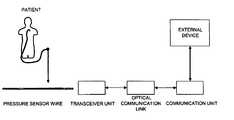
- FIG. 2schematically illustrates a measurement system according to the present invention.
- FIG. 3shows a block diagram schematically illustrating a transceiver unit according to a preferred embodiment of the present invention.
- FIG. 4shows a block diagram schematically illustrating a transceiver unit including a sensor signal adapting circuitry according a preferred embodiment of the present invention.
- FIG. 5shows a block diagram schematically illustrating the optical communication link according to the present invention.
- FIG. 6shows a block diagram schematically illustrating a communication unit according to an alternative embodiment of the present invention.
- a sensor guide wiretypically comprises a core wire, leads and a protective tubing.
- FIG. 1shows an exemplifying sensor mounted on a guide wire in accordance with conventional design which is applicable for the present invention.
- the sensor guide wire 101comprises a hollow tube 102 , a core wire 103 , a first spiral portion 104 , a second spiral portion 105 , a jacket or sleeve 106 , a dome-shaped tip 107 , a sensor element or chip 108 , and one or several electrical leads 109 .
- the tube 102has typically been treated to give the sensor guide construction a smooth outer surface with low friction.
- the proximal end of the first spiral portion 104is attached to the distal end of the hollow tube 102 , while the distal end of the first spiral portion 104 is attached to the proximal end of the jacket 106 .
- the proximal end of the second spiral portion 105is connected to the distal end of the jacket 106 , and the dome-shaped tip 107 is attached to the distal end of the second spiral portion 105 .
- the core wire 103is at least partly disposed inside the hollow tube 102 such that the distal portion of the core wire 103 extends out of the hollow tube 102 and into the second spiral portion 105 .
- the sensor element 108is mounted on the core wire 103 at the position of the jacket 106 , and is connected to an external physiology monitor (not shown in the FIG. 1 ) via the electrical leads 109 .
- the sensor element 108comprises a pressure sensitive device in the form of a membrane (not shown in the FIG. 1 ), which through an aperture 110 in the jacket 106 is in contact with a medium, such as blood, surrounding the distal portion of the sensor guide wire 101 .
- FIG. 2is a schematic overview illustrating the application of the present invention.
- the measurement systemaccording to the present invention comprises a sensor wire with a sensor to measure a physiological condition, e.g. pressure, inside a patient, and to provide measured data to an external device.
- the sensor wireis adapted to be connected, at its proximal end, to a transceiver unit adapted to optically communicate via an optical signal with a communication unit arranged in connection with an external device (also referred to as external physiology monitor), in order to transfer measured data to the external device.
- an external devicealso referred to as external physiology monitor
- the external devicemay be a dedicated device, i.e. a patient monitoring device, preferably provided with a monitor, or a PC provided with relevant software and external connections to receive and to process the measured data from the measurement system.
- a dedicated devicei.e. a patient monitoring device, preferably provided with a monitor, or a PC provided with relevant software and external connections to receive and to process the measured data from the measurement system.
- FIG. 3shows a block diagram schematically illustrating the transceiver unit according to the present invention.
- the transceiver unitis adapted to be connected to the proximal end of a sensor wire provided, at its distal end, with a sensor to measure a physiological condition, e.g. pressure, inside a patient.
- the transceiver unitcomprises a sensor signal adapting circuitry 2 , which will be described in greater detail below, a communication module 4 , connected to the adapting circuitry 2 , that will handle the communication with the communication unit.
- Both one-way and both-way communicationmay be used.
- the measured datais independently generated by the transceiver unit and transferred as an output signal to the communication unit in a prescribed format, to be further discussed below.
- the output signalis preferably in a digital form, i.e. as data packets, where the data is encoded such that the measured values are retrievable to be available and presented by the external device.
- the transmissionmay be an analogue data transmission.
- the sensor wireis adapted to be inserted into an elongated aperture 8 of the transceiver unit.
- the apertureis at its inner surface provided with a number of electrical connecting surfaces (not shown) to be connected to electrode surfaces at the proximal end of the sensor wire when inserted into the aperture 8 .
- the transceiver unitis further provided with wire fastening means (not shown) to firmly fixate the wire when correctly inserted into the aperture.
- the transceiver unitis adapted to receive the proximal end to the sensor wire having an outer diameter of 0.35 mm, i.e. the inner diameter of the elongated aperture 8 must be slightly larger than 0.35 mm.
- U.S. Pat. No. 5,938,624relates to a male connector with a continuous surface for a guide wire which preferably is applied as male connector for the proximal end of the sensor wire to be connected to a transceiver unit according to the present invention.
- the male connectorincludes a core wire, and conductive members spaced apart longitudinally along the core wire.
- a continuous insulating materialis disposed between the guide wire and the conductive members and the insulating material having an outer surface coextensive with outer surfaces of the conductive members.
- the transceiver unit according to the present inventionis provided with a fastening means to fasten the proximal end of the wire to the transceiver unit.
- the fastening meansmay be a female connector of the type disclosed in U.S. Pat. No. 6,428,336 into which a male connector of the kind described above may be inserted and secured to provide electrical contact with contact surfaces of the male connector.
- the female connectorcomprises an insulating hollow housing containing three hollow contact members to make contact with the conductive members of the male connector. At the distal end of the female connector the fastening means for securing the male connector in the female connector are provided.
- the male connector of the sensor wire used in respect of the present inventionis preferably compatible with the female connector disclosed in U.S. Pat. No. 6,428,336.
- the unitWhen the sensor wire is fixated to the transceiver unit the unit may be used as a “handle” when guiding the sensor wire during insertion into a patient.
- the transceiver unitis provided with guiding means 10 , e.g. in the form of one or many elongated ribs on the outer surface of the transceiver unit, or by providing the transceiver unit with a roughened surface.
- the sensor wiremay be fixated to the transceiver unit such that as the transceiver unit is rotated along its longitudinal axis the sensor wire is also rotated, which often is necessary in order to guide the sensor wire during the insertion procedure.
- the sensor wireis fixated to the transceiver unit in such way that the sensor wire may be rotated in relation to the transceiver unit. The rotation of the sensor wire is then achieved by firmly holding the transceiver unit by one hand and by rotating the sensor wire by the other hand.
- the transceiver unitis preferably activated and initiated via an activation button 12 arranged at the housing of the unit.
- the activation buttonis preferably mechanically activated.
- the transceiver unitis activated and initiated when the proximal end to the sensor wire is correctly inserted into the unit. This may e.g. be achieved by arranging a push button at the bottom of the cavity into which the wire is inserted.
- the transceiver unitis activated and initiated when electrical connections are established between corresponding electrical contact surfaces of the female and male connectors, respectively.
- the transceiver unitis activated and initiated by a remote signal generated from the communication unit in response of a command from the monitoring device.
- the transceiver unitcomprises energy means to energize the transceiver unit, the circuitry of the connected sensor wire and the optical communication link, more precisely the distal part of the optical communication link.
- the energy meansis preferably a battery or a capacitor that e.g. may be included in the sensor signal adapting circuitry.
- the sensor wire as well as the transceiver unitare preferably disposable units that must be able to sterilise prior use.
- FIG. 4shows a block diagram schematically illustrating the transceiver unit according to the present invention.
- the sensor wirecomprises a sensor element for measuring the variable and to generate a sensor signal in response of said variable, a guide wire having said sensor element at its distal portion, preferably close to its distal end, and adapted to be inserted into the body in order to position the sensor element within the body.
- the transceiver unitcomprises the sensor signal adapting circuitry ( FIG. 4 ), wherein the sensor signal is applied to the adapting circuitry that is adapted to generate an output signal, related to the sensor signal, in a format such that the measured variable is retrievable by an external device.
- the sensor signal adapting circuitrycomprises a programmable sensor conditioning means, a calibration means, being a storage means into which calibration data may be supplied, stored and altered, e.g. an electrically erasable programmable read-only memory (EEPROM), energy means and an output amplifying means.
- EEPROMelectrically erasable programmable read-only memory
- the programmable sensor conditioning meansis preferably a PGA309 programmable analog sensor conditioner (available from Texas Instruments Inc.) specifically designed for bridge sensors.
- the external devicesupplies the sensor signal adapting circuitry with a reference voltage value optically via the optical connector link and the corresponding voltage is applied from the energy means in the transceiver unit.
- the signal adapting circuitrywill process the signal from the sensor element such that an adapted signal in accordance with the standard expected by the monitor may be optically sent back to the external device.
- the transceiver unitis connected to the optical connector link that in turn is connected to the communication unit.
- the optical connector linkcomprises a first communication means electrically connected to the transceiver unit to handle the communication to and from the transceiver unit, i.e. to convert an electrical signal from the transceiver unit to an optical signal and vice versa.
- the optical connector linkalso comprises a second communication means electrically connected to the communication unit to handle the communication to and from the communication unit, i.e. to convert an optical signal from the transceiver unit to an electrical signal and vice versa.
- the first communication meansis energized by the energy means arranged in the transceiver unit.
- the optical connector linkis realized by at least one commercially available optocoupler, e.g. a high speed optocoupler by Hewlett-Packard having the product number 6N137, HCPL-26XX/06XX/4661 or HCNW137/26X1 that are optically coupled gates that combine a GaAsP light emitting diode and an integrated high gain photo detector.
- optocouplere.g. a high speed optocoupler by Hewlett-Packard having the product number 6N137, HCPL-26XX/06XX/4661 or HCNW137/26X1 that are optically coupled gates that combine a GaAsP light emitting diode and an integrated high gain photo detector.
- an analogue optical transmissionmay be used.
- Examples of available analogue optocouplersare e.g. 6N135, HCPL-0500 and CNW135 by Agilent Technologies. The necessary changes of the circuitry when using this type of optocouplers are obvious to a person skilled in the art.
- the energy consumption of the optocoupleris an important parameter to consider.
- the optocouplerensures that no galvanic connection between the distal part and the proximal part of the measurement system is present.
- the communicationis a one-way communication from the transceiver unit (and the sensor) to the communication unit (and external device).
- the light emitting diodeis arranged at the side facing the transceiver unit and the photo detector faces the communication unit.
- the communicationis a both-way communication, and in that case two optocouplers are arranged enabling communication in both directions.
- more than one optocouplermay be arranged in either direction to provide redundancy for the optical communication link.
- the transceiver unitBy e.g. pressing the activation button on, or by activating the transceiver in another way, the transceiver unit it is activated and will then try to establish an optical connection with the communication unit via the optical connector link. This is preferably performed by a conventional handshake procedure in order to identify the transceiver unit. The system is now ready to receive measured sensor data.
- the sensor valuesis preferably A/D converted and supplied to the optical communication link as a pulse train.
- the programmable sensor conditioning meansis preferably implemented by means of a PGA309 programmable analog sensor conditioner.
- the PGA309is particularly designed for resistive bridge sensor applications and contains three main gain blocks for scaling differential input bridge sensor signals.
- a signal representing the measured physiological variablemay be adapted such that a signal in a format expected by the monitor is provided.
- This signal formatis determined by the reference voltage supplied to the sensor signal adapting circuitry and the actual value of the signal measured by the sensor.
- the PGA309can be configured for use with an internal or external voltage reference. According to the present invention, an internal reference voltage of e.g. +2.5V is supplied to the PGA309 from the energy means.
- the conditioner meansgenerates an analog output voltage signal related to the sensor signal such that the measured physiological variable, i.e. the pressure, may be retrieved by the external device.
- each sensor assemblycomprises a calibration means, preferably an electrically erasable programmable read-only memory (EEPROM) which contains individual calibration data obtained during calibration of the sensor element performed for each individual sensor wire assembly.
- the calibrationis performed in connection with manufacture of the sensor wire. Calibration data takes into account parameters such as voltage offsets and temperature drift, etc.
- the bridge sensoris preferably energized from the PGA309 via an excitation voltage V EXC , generated by the PGA309 circuit, that in turn is energized by the energy source.
- the sensormay be energized from a separate energy source, e.g. a battery or a capacitor means, arranged in the transceiver unit.
- the output voltage (V IN1 -V IN2 ) of the bridgeis a voltage proportional to the physiological condition, e.g. pressure, applied to the sensor.
- the sensor output voltage (V IN1 -V IN2 ) (sensor signal in FIG. 4 ) of the bridgeis proportional to the e.g. pressure applied to the sensor, which for a given pressure will vary with the applied excitation voltage.
- This sensor output voltageis preferably compensated for temperature variation at the site of the sensor and is applied to the PGA309 circuit.
- the PGA309 circuitalso includes gain blocks for adjusting the output signal from that circuit and used in addition to the output amplifying means mentioned above.
- a processing meanspreferably a microprocessor (e.g. a PIC16C770 or a nRF24E1, shown with dashed lines in FIG. 4 ) may further be employed to process and adapt the analog output voltage V OUT of the conditioned sensor, which output voltage is supplied via the PGA309 programmable analog sensor conditioner.
- the analog output signal from the PGA309 circuitis A/D-converted prior it is applied to the processing means.
- DACmultiplying digital-analog converter
- the resulting productis sent via the optical communication link and communication unit to the external device and is proportional to the measured sensor signal and the reference voltage.
- the adaptation of the sensor signal to the standardis performed in the transceiver unit, and in particular in the sensor signal adapting circuitry.
- this adaptationin its entirety or only in parts, may, as an alternative, instead be performed by a corresponding circuitry arranged in the communication unit.
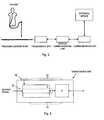
- This embodimentis schematically illustrated in FIG. 6 .
- the transmitted sensor valueswould then be in the form of “raw” measured data that would be conditioned by a processing and conditioning means in the communication unit in order to be in a correct format to be supplied to the external system according to a prescribed standard format.
- the transceiver unit, the optical communication link and the communication unitmay preferably be arranged within a common enclosure, e.g. made from a plastic material, and an electrical wire connection connects the communication unit to the external device.
Landscapes
- Health & Medical Sciences (AREA)
- Life Sciences & Earth Sciences (AREA)
- Heart & Thoracic Surgery (AREA)
- Medical Informatics (AREA)
- Physics & Mathematics (AREA)
- Veterinary Medicine (AREA)
- Biophysics (AREA)
- Pathology (AREA)
- Engineering & Computer Science (AREA)
- Biomedical Technology (AREA)
- Cardiology (AREA)
- Public Health (AREA)
- Molecular Biology (AREA)
- Surgery (AREA)
- Animal Behavior & Ethology (AREA)
- General Health & Medical Sciences (AREA)
- Physiology (AREA)
- Vascular Medicine (AREA)
- Measuring Pulse, Heart Rate, Blood Pressure Or Blood Flow (AREA)
- Measuring And Recording Apparatus For Diagnosis (AREA)
- Electrotherapy Devices (AREA)
Abstract
Description
Claims (26)
Priority Applications (4)
| Application Number | Priority Date | Filing Date | Title |
|---|---|---|---|
| US11/707,278US7946997B2 (en) | 2007-02-16 | 2007-02-16 | Measurement system to measure a physiological condition in a body |
| PCT/SE2008/050111WO2008100208A1 (en) | 2007-02-16 | 2008-01-29 | Measurement system to measure a physiological condition in a body |
| JP2009549556AJP5475468B2 (en) | 2007-02-16 | 2008-01-29 | Device for measuring the physiological state of the body |
| EP08705376AEP2129282A4 (en) | 2007-02-16 | 2008-01-29 | Measurement system to measure a physiological condition in a body |
Applications Claiming Priority (1)
| Application Number | Priority Date | Filing Date | Title |
|---|---|---|---|
| US11/707,278US7946997B2 (en) | 2007-02-16 | 2007-02-16 | Measurement system to measure a physiological condition in a body |
Publications (2)
| Publication Number | Publication Date |
|---|---|
| US20080200770A1 US20080200770A1 (en) | 2008-08-21 |
| US7946997B2true US7946997B2 (en) | 2011-05-24 |
Family
ID=39690340
Family Applications (1)
| Application Number | Title | Priority Date | Filing Date |
|---|---|---|---|
| US11/707,278Expired - Fee RelatedUS7946997B2 (en) | 2007-02-16 | 2007-02-16 | Measurement system to measure a physiological condition in a body |
Country Status (4)
| Country | Link |
|---|---|
| US (1) | US7946997B2 (en) |
| EP (1) | EP2129282A4 (en) |
| JP (1) | JP5475468B2 (en) |
| WO (1) | WO2008100208A1 (en) |
Cited By (132)
| Publication number | Priority date | Publication date | Assignee | Title |
|---|---|---|---|---|
| US20100286536A1 (en)* | 2006-11-20 | 2010-11-11 | St. Jude Medical Systems Ab | Transceiver unit in a measurement system |
| US20110178413A1 (en)* | 2010-01-19 | 2011-07-21 | Schmitt Joseph M | Intravascular optical coherence tomography system with pressure monitoring interface and accessories |
| US20120203118A1 (en)* | 2006-11-20 | 2012-08-09 | St. Jude Medical Systems Ab | Transceiver unit in a measurement system |
| US8926520B2 (en) | 2012-07-20 | 2015-01-06 | Endophys Holdings, Llc | Transducer interface system and method |
| US9167973B2 (en) | 2010-03-08 | 2015-10-27 | Pulsion Medical Systems Se | Portable sensor device and patient monitor |
| US9429713B2 (en) | 2014-04-17 | 2016-08-30 | Boston Scientific Scimed, Inc. | Self-cleaning optical connector |
| US9526909B2 (en) | 2014-08-28 | 2016-12-27 | Cardiac Pacemakers, Inc. | Medical device with triggered blanking period |
| US9592391B2 (en) | 2014-01-10 | 2017-03-14 | Cardiac Pacemakers, Inc. | Systems and methods for detecting cardiac arrhythmias |
| US9669230B2 (en) | 2015-02-06 | 2017-06-06 | Cardiac Pacemakers, Inc. | Systems and methods for treating cardiac arrhythmias |
| US9694189B2 (en) | 2014-08-06 | 2017-07-04 | Cardiac Pacemakers, Inc. | Method and apparatus for communicating between medical devices |
| US9757570B2 (en) | 2014-08-06 | 2017-09-12 | Cardiac Pacemakers, Inc. | Communications in a medical device system |
| US9775523B2 (en) | 2013-10-14 | 2017-10-03 | Boston Scientific Scimed, Inc. | Pressure sensing guidewire and methods for calculating fractional flow reserve |
| US9782129B2 (en) | 2014-08-01 | 2017-10-10 | Boston Scientific Scimed, Inc. | Pressure sensing guidewires |
| US9795307B2 (en) | 2014-12-05 | 2017-10-24 | Boston Scientific Scimed, Inc. | Pressure sensing guidewires |
| US9808631B2 (en) | 2014-08-06 | 2017-11-07 | Cardiac Pacemakers, Inc. | Communication between a plurality of medical devices using time delays between communication pulses to distinguish between symbols |
| US9853743B2 (en) | 2015-08-20 | 2017-12-26 | Cardiac Pacemakers, Inc. | Systems and methods for communication between medical devices |
| US9877660B2 (en) | 2013-11-14 | 2018-01-30 | Medtronic Vascular Galway | Systems and methods for determining fractional flow reserve without adenosine or other pharmalogical agent |
| US9913585B2 (en) | 2014-01-15 | 2018-03-13 | Medtronic Vascular, Inc. | Catheter for providing vascular pressure measurements |
| US9956414B2 (en) | 2015-08-27 | 2018-05-01 | Cardiac Pacemakers, Inc. | Temporal configuration of a motion sensor in an implantable medical device |
| US9968787B2 (en) | 2015-08-27 | 2018-05-15 | Cardiac Pacemakers, Inc. | Spatial configuration of a motion sensor in an implantable medical device |
| US10029107B1 (en) | 2017-01-26 | 2018-07-24 | Cardiac Pacemakers, Inc. | Leadless device with overmolded components |
| US10028666B2 (en) | 2013-03-15 | 2018-07-24 | Boston Scientific Scimed, Inc. | Pressure sensing guidewire |
| US10046167B2 (en) | 2015-02-09 | 2018-08-14 | Cardiac Pacemakers, Inc. | Implantable medical device with radiopaque ID tag |
| US10050700B2 (en) | 2015-03-18 | 2018-08-14 | Cardiac Pacemakers, Inc. | Communications in a medical device system with temporal optimization |
| US10065041B2 (en) | 2015-10-08 | 2018-09-04 | Cardiac Pacemakers, Inc. | Devices and methods for adjusting pacing rates in an implantable medical device |
| US10092760B2 (en) | 2015-09-11 | 2018-10-09 | Cardiac Pacemakers, Inc. | Arrhythmia detection and confirmation |
| US10130269B2 (en) | 2013-11-14 | 2018-11-20 | Medtronic Vascular, Inc | Dual lumen catheter for providing a vascular pressure measurement |
| US10137305B2 (en) | 2015-08-28 | 2018-11-27 | Cardiac Pacemakers, Inc. | Systems and methods for behaviorally responsive signal detection and therapy delivery |
| US10159842B2 (en) | 2015-08-28 | 2018-12-25 | Cardiac Pacemakers, Inc. | System and method for detecting tamponade |
| US10183170B2 (en) | 2015-12-17 | 2019-01-22 | Cardiac Pacemakers, Inc. | Conducted communication in a medical device system |
| US10194812B2 (en) | 2014-12-12 | 2019-02-05 | Medtronic Vascular, Inc. | System and method of integrating a fractional flow reserve device with a conventional hemodynamic monitoring system |
| US10201284B2 (en) | 2014-06-16 | 2019-02-12 | Medtronic Vascular Inc. | Pressure measuring catheter having reduced error from bending stresses |
| US10213610B2 (en) | 2015-03-18 | 2019-02-26 | Cardiac Pacemakers, Inc. | Communications in a medical device system with link quality assessment |
| US10220213B2 (en) | 2015-02-06 | 2019-03-05 | Cardiac Pacemakers, Inc. | Systems and methods for safe delivery of electrical stimulation therapy |
| US10226631B2 (en) | 2015-08-28 | 2019-03-12 | Cardiac Pacemakers, Inc. | Systems and methods for infarct detection |
| US10258240B1 (en) | 2014-11-24 | 2019-04-16 | Vascular Imaging Corporation | Optical fiber pressure sensor |
| US10278594B2 (en) | 2014-06-04 | 2019-05-07 | Boston Scientific Scimed, Inc. | Pressure sensing guidewire systems with reduced pressure offsets |
| US10307070B2 (en) | 2014-04-04 | 2019-06-04 | St. Jude Medical Coordination Center Bvba | Intravascular pressure and flow data diagnostic systems, devices, and methods |
| US10328272B2 (en) | 2016-05-10 | 2019-06-25 | Cardiac Pacemakers, Inc. | Retrievability for implantable medical devices |
| US10327645B2 (en) | 2013-10-04 | 2019-06-25 | Vascular Imaging Corporation | Imaging techniques using an imaging guidewire |
| US10350423B2 (en) | 2016-02-04 | 2019-07-16 | Cardiac Pacemakers, Inc. | Delivery system with force sensor for leadless cardiac device |
| US10357159B2 (en) | 2015-08-20 | 2019-07-23 | Cardiac Pacemakers, Inc | Systems and methods for communication between medical devices |
| US10391319B2 (en) | 2016-08-19 | 2019-08-27 | Cardiac Pacemakers, Inc. | Trans septal implantable medical device |
| US10413733B2 (en) | 2016-10-27 | 2019-09-17 | Cardiac Pacemakers, Inc. | Implantable medical device with gyroscope |
| US10426962B2 (en) | 2016-07-07 | 2019-10-01 | Cardiac Pacemakers, Inc. | Leadless pacemaker using pressure measurements for pacing capture verification |
| US10434314B2 (en) | 2016-10-27 | 2019-10-08 | Cardiac Pacemakers, Inc. | Use of a separate device in managing the pace pulse energy of a cardiac pacemaker |
| US10434317B2 (en) | 2016-10-31 | 2019-10-08 | Cardiac Pacemakers, Inc. | Systems and methods for activity level pacing |
| US10463305B2 (en) | 2016-10-27 | 2019-11-05 | Cardiac Pacemakers, Inc. | Multi-device cardiac resynchronization therapy with timing enhancements |
| US10499820B2 (en) | 2013-05-22 | 2019-12-10 | Boston Scientific Scimed, Inc. | Pressure sensing guidewire systems including an optical connector cable |
| US10506934B2 (en) | 2012-05-25 | 2019-12-17 | Phyzhon Health Inc. | Optical fiber pressure sensor |
| US10512784B2 (en) | 2016-06-27 | 2019-12-24 | Cardiac Pacemakers, Inc. | Cardiac therapy system using subcutaneously sensed P-waves for resynchronization pacing management |
| US10537255B2 (en) | 2013-11-21 | 2020-01-21 | Phyzhon Health Inc. | Optical fiber pressure sensor |
| US10548489B2 (en) | 2014-10-31 | 2020-02-04 | Lake Region Medical, Inc. | Fiber Bragg grating multi-point pressure sensing guidewire with birefringent component |
| US10561330B2 (en) | 2016-10-27 | 2020-02-18 | Cardiac Pacemakers, Inc. | Implantable medical device having a sense channel with performance adjustment |
| US10583303B2 (en) | 2016-01-19 | 2020-03-10 | Cardiac Pacemakers, Inc. | Devices and methods for wirelessly recharging a rechargeable battery of an implantable medical device |
| US10582860B2 (en) | 2012-08-27 | 2020-03-10 | Boston Scientific Scimed, Inc. | Pressure-sensing medical devices and medical device systems |
| US10583301B2 (en) | 2016-11-08 | 2020-03-10 | Cardiac Pacemakers, Inc. | Implantable medical device for atrial deployment |
| US10617874B2 (en) | 2016-10-31 | 2020-04-14 | Cardiac Pacemakers, Inc. | Systems and methods for activity level pacing |
| US10632313B2 (en) | 2016-11-09 | 2020-04-28 | Cardiac Pacemakers, Inc. | Systems, devices, and methods for setting cardiac pacing pulse parameters for a cardiac pacing device |
| US10639486B2 (en) | 2016-11-21 | 2020-05-05 | Cardiac Pacemakers, Inc. | Implantable medical device with recharge coil |
| US10648918B2 (en) | 2011-08-03 | 2020-05-12 | Lightlab Imaging, Inc. | Systems, methods and apparatus for determining a fractional flow reserve (FFR) based on the minimum lumen area (MLA) and the constant |
| US10646122B2 (en) | 2017-04-28 | 2020-05-12 | Medtronic Vascular, Inc. | FFR catheter with covered distal pressure sensor and method of manufacture |
| US10668294B2 (en) | 2016-05-10 | 2020-06-02 | Cardiac Pacemakers, Inc. | Leadless cardiac pacemaker configured for over the wire delivery |
| US10688304B2 (en) | 2016-07-20 | 2020-06-23 | Cardiac Pacemakers, Inc. | Method and system for utilizing an atrial contraction timing fiducial in a leadless cardiac pacemaker system |
| US10702162B2 (en) | 2010-11-09 | 2020-07-07 | Opsens Inc. | Guidewire with internal pressure sensor |
| US10722720B2 (en) | 2014-01-10 | 2020-07-28 | Cardiac Pacemakers, Inc. | Methods and systems for improved communication between medical devices |
| US10737102B2 (en) | 2017-01-26 | 2020-08-11 | Cardiac Pacemakers, Inc. | Leadless implantable device with detachable fixation |
| US10758724B2 (en) | 2016-10-27 | 2020-09-01 | Cardiac Pacemakers, Inc. | Implantable medical device delivery system with integrated sensor |
| US10758737B2 (en) | 2016-09-21 | 2020-09-01 | Cardiac Pacemakers, Inc. | Using sensor data from an intracardially implanted medical device to influence operation of an extracardially implantable cardioverter |
| US10765871B2 (en) | 2016-10-27 | 2020-09-08 | Cardiac Pacemakers, Inc. | Implantable medical device with pressure sensor |
| US10780278B2 (en) | 2016-08-24 | 2020-09-22 | Cardiac Pacemakers, Inc. | Integrated multi-device cardiac resynchronization therapy using P-wave to pace timing |
| US10821288B2 (en) | 2017-04-03 | 2020-11-03 | Cardiac Pacemakers, Inc. | Cardiac pacemaker with pacing pulse energy adjustment based on sensed heart rate |
| US10835753B2 (en) | 2017-01-26 | 2020-11-17 | Cardiac Pacemakers, Inc. | Intra-body device communication with redundant message transmission |
| US10835182B2 (en) | 2013-08-14 | 2020-11-17 | Boston Scientific Scimed, Inc. | Medical device systems including an optical fiber with a tapered core |
| US10870008B2 (en) | 2016-08-24 | 2020-12-22 | Cardiac Pacemakers, Inc. | Cardiac resynchronization using fusion promotion for timing management |
| US10874861B2 (en) | 2018-01-04 | 2020-12-29 | Cardiac Pacemakers, Inc. | Dual chamber pacing without beat-to-beat communication |
| US10881863B2 (en) | 2016-11-21 | 2021-01-05 | Cardiac Pacemakers, Inc. | Leadless cardiac pacemaker with multimode communication |
| US10881869B2 (en) | 2016-11-21 | 2021-01-05 | Cardiac Pacemakers, Inc. | Wireless re-charge of an implantable medical device |
| US10894163B2 (en) | 2016-11-21 | 2021-01-19 | Cardiac Pacemakers, Inc. | LCP based predictive timing for cardiac resynchronization |
| US10905889B2 (en) | 2016-09-21 | 2021-02-02 | Cardiac Pacemakers, Inc. | Leadless stimulation device with a housing that houses internal components of the leadless stimulation device and functions as the battery case and a terminal of an internal battery |
| US10905872B2 (en) | 2017-04-03 | 2021-02-02 | Cardiac Pacemakers, Inc. | Implantable medical device with a movable electrode biased toward an extended position |
| US10905886B2 (en) | 2015-12-28 | 2021-02-02 | Cardiac Pacemakers, Inc. | Implantable medical device for deployment across the atrioventricular septum |
| US10918875B2 (en) | 2017-08-18 | 2021-02-16 | Cardiac Pacemakers, Inc. | Implantable medical device with a flux concentrator and a receiving coil disposed about the flux concentrator |
| US10932679B2 (en) | 2014-03-18 | 2021-03-02 | Boston Scientific Scimed, Inc. | Pressure sensing guidewires and methods of use |
| US10973418B2 (en) | 2014-06-16 | 2021-04-13 | Medtronic Vascular, Inc. | Microcatheter sensor design for minimizing profile and impact of wire strain on sensor |
| US10994145B2 (en) | 2016-09-21 | 2021-05-04 | Cardiac Pacemakers, Inc. | Implantable cardiac monitor |
| US11052258B2 (en) | 2017-12-01 | 2021-07-06 | Cardiac Pacemakers, Inc. | Methods and systems for detecting atrial contraction timing fiducials within a search window from a ventricularly implanted leadless cardiac pacemaker |
| US11058307B2 (en) | 2016-02-23 | 2021-07-13 | Boston Scientific Scimed, Inc. | Pressure sensing guidewire systems including an optical connector cable |
| US11058880B2 (en) | 2018-03-23 | 2021-07-13 | Medtronic, Inc. | VFA cardiac therapy for tachycardia |
| US11065459B2 (en) | 2017-08-18 | 2021-07-20 | Cardiac Pacemakers, Inc. | Implantable medical device with pressure sensor |
| US11071870B2 (en) | 2017-12-01 | 2021-07-27 | Cardiac Pacemakers, Inc. | Methods and systems for detecting atrial contraction timing fiducials and determining a cardiac interval from a ventricularly implanted leadless cardiac pacemaker |
| US11076765B2 (en) | 2013-07-26 | 2021-08-03 | Boston Scientific Scimed, Inc. | FFR sensor head design that minimizes stress induced pressure offsets |
| US11116988B2 (en) | 2016-03-31 | 2021-09-14 | Cardiac Pacemakers, Inc. | Implantable medical device with rechargeable battery |
| US11147979B2 (en) | 2016-11-21 | 2021-10-19 | Cardiac Pacemakers, Inc. | Implantable medical device with a magnetically permeable housing and an inductive coil disposed about the housing |
| US11185703B2 (en) | 2017-11-07 | 2021-11-30 | Cardiac Pacemakers, Inc. | Leadless cardiac pacemaker for bundle of his pacing |
| US11185244B2 (en) | 2018-08-13 | 2021-11-30 | Medtronic Vascular, Inc. | FFR catheter with suspended pressure sensor |
| US11207532B2 (en) | 2017-01-04 | 2021-12-28 | Cardiac Pacemakers, Inc. | Dynamic sensing updates using postural input in a multiple device cardiac rhythm management system |
| US11207527B2 (en) | 2016-07-06 | 2021-12-28 | Cardiac Pacemakers, Inc. | Method and system for determining an atrial contraction timing fiducial in a leadless cardiac pacemaker system |
| US11213676B2 (en) | 2019-04-01 | 2022-01-04 | Medtronic, Inc. | Delivery systems for VfA cardiac therapy |
| US11219741B2 (en) | 2017-08-09 | 2022-01-11 | Medtronic Vascular, Inc. | Collapsible catheter and method for calculating fractional flow reserve |
| US11235161B2 (en) | 2018-09-26 | 2022-02-01 | Medtronic, Inc. | Capture in ventricle-from-atrium cardiac therapy |
| US11235124B2 (en) | 2017-08-09 | 2022-02-01 | Medtronic Vascular, Inc. | Collapsible catheter and method for calculating fractional flow reserve |
| US11235163B2 (en) | 2017-09-20 | 2022-02-01 | Cardiac Pacemakers, Inc. | Implantable medical device with multiple modes of operation |
| US11234650B2 (en) | 2006-11-20 | 2022-02-01 | St. Jude Medical Coordination Center Bvba | Measurement system |
| US11235159B2 (en) | 2018-03-23 | 2022-02-01 | Medtronic, Inc. | VFA cardiac resynchronization therapy |
| US11241154B2 (en) | 2011-05-31 | 2022-02-08 | Lightlab Imaging, Inc. | Multimodal imaging system, apparatus, and methods |
| US11260216B2 (en) | 2017-12-01 | 2022-03-01 | Cardiac Pacemakers, Inc. | Methods and systems for detecting atrial contraction timing fiducials during ventricular filling from a ventricularly implanted leadless cardiac pacemaker |
| US11272850B2 (en) | 2016-08-09 | 2022-03-15 | Medtronic Vascular, Inc. | Catheter and method for calculating fractional flow reserve |
| US11285326B2 (en) | 2015-03-04 | 2022-03-29 | Cardiac Pacemakers, Inc. | Systems and methods for treating cardiac arrhythmias |
| US11305127B2 (en) | 2019-08-26 | 2022-04-19 | Medtronic Inc. | VfA delivery and implant region detection |
| US11311196B2 (en) | 2018-02-23 | 2022-04-26 | Boston Scientific Scimed, Inc. | Methods for assessing a vessel with sequential physiological measurements |
| US11330989B2 (en) | 2014-06-16 | 2022-05-17 | Medtronic Vascular, Inc. | Microcatheter sensor design for mounting sensor to minimize induced strain |
| US11330994B2 (en) | 2017-03-08 | 2022-05-17 | Medtronic Vascular, Inc. | Reduced profile FFR catheter |
| US11400296B2 (en) | 2018-03-23 | 2022-08-02 | Medtronic, Inc. | AV synchronous VfA cardiac therapy |
| US11529523B2 (en) | 2018-01-04 | 2022-12-20 | Cardiac Pacemakers, Inc. | Handheld bridge device for providing a communication bridge between an implanted medical device and a smartphone |
| US11559213B2 (en) | 2018-04-06 | 2023-01-24 | Boston Scientific Scimed, Inc. | Medical device with pressure sensor |
| US11564581B2 (en) | 2017-08-03 | 2023-01-31 | Boston Scientific Scimed, Inc. | Methods for assessing fractional flow reserve |
| US11666232B2 (en) | 2018-04-18 | 2023-06-06 | Boston Scientific Scimed, Inc. | Methods for assessing a vessel with sequential physiological measurements |
| US11679265B2 (en) | 2019-02-14 | 2023-06-20 | Medtronic, Inc. | Lead-in-lead systems and methods for cardiac therapy |
| US11697025B2 (en) | 2019-03-29 | 2023-07-11 | Medtronic, Inc. | Cardiac conduction system capture |
| US11712188B2 (en) | 2019-05-07 | 2023-08-01 | Medtronic, Inc. | Posterior left bundle branch engagement |
| US11813463B2 (en) | 2017-12-01 | 2023-11-14 | Cardiac Pacemakers, Inc. | Leadless cardiac pacemaker with reversionary behavior |
| US11813466B2 (en) | 2020-01-27 | 2023-11-14 | Medtronic, Inc. | Atrioventricular nodal stimulation |
| US11813464B2 (en) | 2020-07-31 | 2023-11-14 | Medtronic, Inc. | Cardiac conduction system evaluation |
| US11850073B2 (en) | 2018-03-23 | 2023-12-26 | Boston Scientific Scimed, Inc. | Medical device with pressure sensor |
| US11911168B2 (en) | 2020-04-03 | 2024-02-27 | Medtronic, Inc. | Cardiac conduction system therapy benefit determination |
| US11951313B2 (en) | 2018-11-17 | 2024-04-09 | Medtronic, Inc. | VFA delivery systems and methods |
| US12029533B2 (en) | 2013-07-18 | 2024-07-09 | Endophys Holdings, Llc | Blood pressure analysis system and method |
| US12087000B2 (en) | 2021-03-05 | 2024-09-10 | Boston Scientific Scimed, Inc. | Systems and methods for vascular image co-registration |
| US12296177B2 (en) | 2018-12-21 | 2025-05-13 | Medtronic, Inc. | Delivery systems and methods for left ventricular pacing |
| US12310704B2 (en) | 2019-09-13 | 2025-05-27 | Endophys Holdings, Llc | Blood pressure monitoring with zero function system and method |
| US12383246B2 (en) | 2020-10-12 | 2025-08-12 | Abbott Cardiovascular Systems, Inc. | Vessel closure device with improved safety and tract hemostasis |
Families Citing this family (51)
| Publication number | Priority date | Publication date | Assignee | Title |
|---|---|---|---|---|
| US7998089B2 (en)* | 2007-11-08 | 2011-08-16 | Radi Medical Systems Ab | Method of making a guide wire based assembly and reusing an energy source |
| US9095685B2 (en)* | 2008-01-23 | 2015-08-04 | Mediguide Ltd. | Sensor mounted flexible guidewire |
| US9788790B2 (en) | 2009-05-28 | 2017-10-17 | Avinger, Inc. | Optical coherence tomography for biological imaging |
| US8062316B2 (en) | 2008-04-23 | 2011-11-22 | Avinger, Inc. | Catheter system and method for boring through blocked vascular passages |
| US8696695B2 (en) | 2009-04-28 | 2014-04-15 | Avinger, Inc. | Guidewire positioning catheter |
| US9125562B2 (en) | 2009-07-01 | 2015-09-08 | Avinger, Inc. | Catheter-based off-axis optical coherence tomography imaging system |
| WO2011003006A2 (en) | 2009-07-01 | 2011-01-06 | Avinger, Inc. | Atherectomy catheter with laterally-displaceable tip |
| US9301699B2 (en) | 2009-09-18 | 2016-04-05 | St. Jude Medical Coordination Center Bvba | Device for acquiring physiological variables measured in a body |
| SE1050086A1 (en)* | 2010-01-27 | 2011-06-28 | St Jude Medical Systems Ab | Sensor control wire device and system for intravascular measurements of a physiological variable |
| SE535022C2 (en) | 2010-06-30 | 2012-03-20 | St Jude Medical Systems Ab | Sensor guide wire comprising a multi-hole sensor capsule |
| US11382653B2 (en) | 2010-07-01 | 2022-07-12 | Avinger, Inc. | Atherectomy catheter |
| US10548478B2 (en) | 2010-07-01 | 2020-02-04 | Avinger, Inc. | Balloon atherectomy catheters with imaging |
| WO2014039096A1 (en) | 2012-09-06 | 2014-03-13 | Avinger, Inc. | Re-entry stylet for catheter |
| US9345510B2 (en) | 2010-07-01 | 2016-05-24 | Avinger, Inc. | Atherectomy catheters with longitudinally displaceable drive shafts |
| US8814792B2 (en) | 2010-07-27 | 2014-08-26 | Carefusion 303, Inc. | System and method for storing and forwarding data from a vital-signs monitor |
| US9420952B2 (en) | 2010-07-27 | 2016-08-23 | Carefusion 303, Inc. | Temperature probe suitable for axillary reading |
| US9615792B2 (en) | 2010-07-27 | 2017-04-11 | Carefusion 303, Inc. | System and method for conserving battery power in a patient monitoring system |
| US9055925B2 (en) | 2010-07-27 | 2015-06-16 | Carefusion 303, Inc. | System and method for reducing false alarms associated with vital-signs monitoring |
| US9585620B2 (en) | 2010-07-27 | 2017-03-07 | Carefusion 303, Inc. | Vital-signs patch having a flexible attachment to electrodes |
| US9357929B2 (en) | 2010-07-27 | 2016-06-07 | Carefusion 303, Inc. | System and method for monitoring body temperature of a person |
| US9017255B2 (en) | 2010-07-27 | 2015-04-28 | Carefusion 303, Inc. | System and method for saving battery power in a patient monitoring system |
| US20120030547A1 (en)* | 2010-07-27 | 2012-02-02 | Carefusion 303, Inc. | System and method for saving battery power in a vital-signs monitor |
| SE537180C2 (en)* | 2010-11-12 | 2015-02-24 | St Jude Medical Systems Ab | Extracorporeal interface unit for an intravascular measurement system |
| US9949754B2 (en) | 2011-03-28 | 2018-04-24 | Avinger, Inc. | Occlusion-crossing devices |
| EP2691038B1 (en) | 2011-03-28 | 2016-07-20 | Avinger, Inc. | Occlusion-crossing devices, imaging, and atherectomy devices |
| EP3653151A1 (en) | 2011-10-17 | 2020-05-20 | Avinger, Inc. | Atherectomy catheters and non-contact actuation mechanism for catheters |
| US9345406B2 (en) | 2011-11-11 | 2016-05-24 | Avinger, Inc. | Occlusion-crossing devices, atherectomy devices, and imaging |
| EP2844135B1 (en)* | 2012-05-03 | 2022-06-29 | St. Jude Medical Coordination Center BVBA | Tube and sensor guide wire comprising tube |
| US9557156B2 (en) | 2012-05-14 | 2017-01-31 | Avinger, Inc. | Optical coherence tomography with graded index fiber for biological imaging |
| EP2849660B1 (en) | 2012-05-14 | 2021-08-25 | Avinger, Inc. | Atherectomy catheter drive assemblies |
| WO2013172970A1 (en) | 2012-05-14 | 2013-11-21 | Avinger, Inc. | Atherectomy catheters with imaging |
| US11284916B2 (en) | 2012-09-06 | 2022-03-29 | Avinger, Inc. | Atherectomy catheters and occlusion crossing devices |
| US9498247B2 (en) | 2014-02-06 | 2016-11-22 | Avinger, Inc. | Atherectomy catheters and occlusion crossing devices |
| JP2016501674A (en)* | 2012-12-28 | 2016-01-21 | ヴォルカノ コーポレイションVolcano Corporation | Intravascular device, system, and method with information stored in the intravascular device and / or wireless communication capability with associated devices |
| CN105228514B (en)* | 2013-03-15 | 2019-01-22 | 阿维格公司 | Optical Pressure Sensor Assembly |
| US11096717B2 (en) | 2013-03-15 | 2021-08-24 | Avinger, Inc. | Tissue collection device for catheter |
| WO2014143064A1 (en) | 2013-03-15 | 2014-09-18 | Avinger, Inc. | Chronic total occlusion crossing devices with imaging |
| EP3019096B1 (en) | 2013-07-08 | 2023-07-05 | Avinger, Inc. | System for identification of elastic lamina to guide interventional therapy |
| JP6568056B2 (en)* | 2013-10-14 | 2019-08-28 | ボルケーノ コーポレイション | Intravascular device, system, and method |
| JP6395826B2 (en) | 2013-10-25 | 2018-09-26 | セント ジュード メディカル コーディネイション センター ベーファウベーアー | SENSOR GUIDE WIRE DEVICE AND SYSTEM WITH SENSOR GUIDE WIRE DEVICE |
| MX2016010141A (en) | 2014-02-06 | 2017-04-06 | Avinger Inc | Atherectomy catheters and occlusion crossing devices. |
| US10357277B2 (en) | 2014-07-08 | 2019-07-23 | Avinger, Inc. | High speed chronic total occlusion crossing devices |
| US10898090B2 (en) | 2015-02-26 | 2021-01-26 | St. Jude Medical Coordination Center Bvba | Pressure sensor and guide wire with self wetting tube |
| US10568520B2 (en) | 2015-07-13 | 2020-02-25 | Avinger, Inc. | Micro-molded anamorphic reflector lens for image guided therapeutic/diagnostic catheters |
| JP6927986B2 (en) | 2016-01-25 | 2021-09-01 | アビンガー・インコーポレイテッドAvinger, Inc. | OCT imaging catheter with delay compensation |
| EP3435892B1 (en) | 2016-04-01 | 2024-04-03 | Avinger, Inc. | Atherectomy catheter with serrated cutter |
| US11344327B2 (en) | 2016-06-03 | 2022-05-31 | Avinger, Inc. | Catheter device with detachable distal end |
| WO2018006041A1 (en) | 2016-06-30 | 2018-01-04 | Avinger, Inc. | Atherectomy catheter with shapeable distal tip |
| US10699559B2 (en) | 2016-09-02 | 2020-06-30 | Koninklijke Philips N.V. | Optical transceiver, optical system, interventional device and method for supplying energy and returning data |
| US12167867B2 (en) | 2018-04-19 | 2024-12-17 | Avinger, Inc. | Occlusion-crossing devices |
| CN114746033B (en) | 2019-10-18 | 2025-01-10 | 阿维格公司 | Blocking crossing device |
Citations (13)
| Publication number | Priority date | Publication date | Assignee | Title |
|---|---|---|---|---|
| US5498261A (en)* | 1991-12-20 | 1996-03-12 | Advanced Cardiovascular Systems, Inc. | Thermal angioplasty system |
| EP0712603A2 (en) | 1994-11-21 | 1996-05-22 | Becton, Dickinson and Company | A self-powered interface circuit for use with a transducer sensor |
| WO1998042253A1 (en) | 1997-03-25 | 1998-10-01 | Radi Medical Systems Ab | Device for pressure measurements |
| US5938624A (en) | 1997-09-10 | 1999-08-17 | Radi Medical Systems Ab | Male connector with a continous surface for a guide wire and method therefor |
| US6167763B1 (en) | 1995-06-22 | 2001-01-02 | Radi Medical Systems Ab | Pressure sensor and guide wire assembly for biological pressure measurements |
| WO2001018835A1 (en) | 1999-09-08 | 2001-03-15 | Endosonics Corporation | Medical device having precision interconnect |
| US20010021799A1 (en) | 2000-03-09 | 2001-09-13 | Siemens Elema Ab | Interface unit for an electrophysiological monitoring system |
| US6428336B1 (en) | 1997-03-25 | 2002-08-06 | Radi Medical Systems Ab | Female connector |
| US20020173724A1 (en) | 2001-05-18 | 2002-11-21 | Dorando Dale Gene | Signal conditioning device for interfacing intravascular sensors having varying operational characteristics to a physiology monitor |
| US6565514B2 (en) | 2000-08-25 | 2003-05-20 | Radi Medical Systems Ab | Method and system for determining physiological variables |
| US6615067B2 (en) | 2000-03-21 | 2003-09-02 | Radi Medical Systems Ab | Method and device for measuring physical characteristics in a body |
| US6618603B2 (en)* | 2000-05-08 | 2003-09-09 | Menarini Industrie Farmaceutiche Riunite S.R.L. | Apparatus for measurement and control of the content of glucose, lactate or other metabolites in biological fluids |
| EP1616521B1 (en) | 2004-07-12 | 2007-11-21 | Radi Medical Systems Ab | Wireless communication of physiological variables |
Family Cites Families (13)
| Publication number | Priority date | Publication date | Assignee | Title |
|---|---|---|---|---|
| US4858617A (en)* | 1987-09-10 | 1989-08-22 | Ith, Inc. | Cardiac probe enabling use of personal computer for monitoring heart activity or the like |
| US4903340A (en)* | 1988-03-23 | 1990-02-20 | Spacelabs, Inc. | Optical data connector having magnetic interconnect sensor |
| JPH0268033A (en)* | 1988-09-02 | 1990-03-07 | Aisin Seiki Co Ltd | In vivo information transmitting device and in vivo information monitoring device |
| US5215523A (en)* | 1991-05-30 | 1993-06-01 | Eli Williams | Balloon catheter inflation syringe with remote display |
| DE69534748T2 (en)* | 1994-09-02 | 2006-11-02 | Volcano Corp. (n.d, Ges.d.Staates Delaware), Rancho Cordova | ULTRAMINIATUR PRESSURE SENSOR AND GUIDE WIRE THEREFORE |
| JPH0970392A (en)* | 1995-07-04 | 1997-03-18 | Tokai Rika Co Ltd | Living body pressure measuring apparatus |
| JPH09187428A (en)* | 1996-01-04 | 1997-07-22 | Aloka Co Ltd | Medical electronic apparatus |
| JPH1033488A (en)* | 1996-07-26 | 1998-02-10 | Tokai Rika Co Ltd | Pressure sensor |
| JP3460600B2 (en)* | 1998-11-20 | 2003-10-27 | 松下電器産業株式会社 | Non-invasive continuous sphygmomanometer |
| SG152019A1 (en)* | 2003-01-29 | 2009-05-29 | Healthstats Int Pte Ltd | Noninvasive blood pressure monitoring system |
| JP4449055B2 (en)* | 2003-11-27 | 2010-04-14 | 日本光電工業株式会社 | Biological signal data transmission / reception system and biological signal data transmission / reception method |
| JP2006026406A (en)* | 2004-07-12 | 2006-02-02 | Radi Medical Systems Ab | Radio communication for physiological variable |
| DE102005003171A1 (en)* | 2005-01-19 | 2006-08-03 | Biotronik Crm Patent Ag | Medical catheter has an integral power supply and a wireless data transfer interface for the transmission of medical data and measurements to an external diagnosis and control device |
- 2007
- 2007-02-16USUS11/707,278patent/US7946997B2/ennot_activeExpired - Fee Related
- 2008
- 2008-01-29EPEP08705376Apatent/EP2129282A4/ennot_activeWithdrawn
- 2008-01-29WOPCT/SE2008/050111patent/WO2008100208A1/enactiveApplication Filing
- 2008-01-29JPJP2009549556Apatent/JP5475468B2/ennot_activeExpired - Fee Related
Patent Citations (14)
| Publication number | Priority date | Publication date | Assignee | Title |
|---|---|---|---|---|
| US5498261A (en)* | 1991-12-20 | 1996-03-12 | Advanced Cardiovascular Systems, Inc. | Thermal angioplasty system |
| EP0712603A2 (en) | 1994-11-21 | 1996-05-22 | Becton, Dickinson and Company | A self-powered interface circuit for use with a transducer sensor |
| US5568815A (en) | 1994-11-21 | 1996-10-29 | Becton Dickinson And Company | Self-powered interface circuit for use with a transducer sensor |
| US6167763B1 (en) | 1995-06-22 | 2001-01-02 | Radi Medical Systems Ab | Pressure sensor and guide wire assembly for biological pressure measurements |
| US6428336B1 (en) | 1997-03-25 | 2002-08-06 | Radi Medical Systems Ab | Female connector |
| WO1998042253A1 (en) | 1997-03-25 | 1998-10-01 | Radi Medical Systems Ab | Device for pressure measurements |
| US5938624A (en) | 1997-09-10 | 1999-08-17 | Radi Medical Systems Ab | Male connector with a continous surface for a guide wire and method therefor |
| WO2001018835A1 (en) | 1999-09-08 | 2001-03-15 | Endosonics Corporation | Medical device having precision interconnect |
| US20010021799A1 (en) | 2000-03-09 | 2001-09-13 | Siemens Elema Ab | Interface unit for an electrophysiological monitoring system |
| US6615067B2 (en) | 2000-03-21 | 2003-09-02 | Radi Medical Systems Ab | Method and device for measuring physical characteristics in a body |
| US6618603B2 (en)* | 2000-05-08 | 2003-09-09 | Menarini Industrie Farmaceutiche Riunite S.R.L. | Apparatus for measurement and control of the content of glucose, lactate or other metabolites in biological fluids |
| US6565514B2 (en) | 2000-08-25 | 2003-05-20 | Radi Medical Systems Ab | Method and system for determining physiological variables |
| US20020173724A1 (en) | 2001-05-18 | 2002-11-21 | Dorando Dale Gene | Signal conditioning device for interfacing intravascular sensors having varying operational characteristics to a physiology monitor |
| EP1616521B1 (en) | 2004-07-12 | 2007-11-21 | Radi Medical Systems Ab | Wireless communication of physiological variables |
Cited By (177)
| Publication number | Priority date | Publication date | Assignee | Title |
|---|---|---|---|---|
| US11813086B2 (en) | 2006-11-20 | 2023-11-14 | St. Jude Medical Coordination Center Bvba | Measurement system |
| US9585566B2 (en) | 2006-11-20 | 2017-03-07 | St. Jude Medical Coordination Center Bvba | Transceiver unit in a measurement system |
| US20120203118A1 (en)* | 2006-11-20 | 2012-08-09 | St. Jude Medical Systems Ab | Transceiver unit in a measurement system |
| US8410940B2 (en)* | 2006-11-20 | 2013-04-02 | St. Jude Medical Systems Ab | Transceiver unit in a measurement system |
| US8461997B2 (en) | 2006-11-20 | 2013-06-11 | St. Jude Medical Systems Ab | Transceiver unit in a measurement system |
| US11234650B2 (en) | 2006-11-20 | 2022-02-01 | St. Jude Medical Coordination Center Bvba | Measurement system |
| US20100286536A1 (en)* | 2006-11-20 | 2010-11-11 | St. Jude Medical Systems Ab | Transceiver unit in a measurement system |
| US8698638B2 (en) | 2006-11-20 | 2014-04-15 | St. Jude Medical Systems Ab | Transceiver unit in a measurement system |
| US10314488B2 (en) | 2006-11-20 | 2019-06-11 | St. Jude Medical Coordination Center Bvba | Measurement system |
| US9888848B2 (en) | 2006-11-20 | 2018-02-13 | St. Jude Medical Coordination Center Bvba | Measurement system |
| US10736573B2 (en) | 2006-11-20 | 2020-08-11 | St. Jude Medical Coordination Center Bvba | Measurement system |
| US9220461B2 (en) | 2006-11-20 | 2015-12-29 | St. Jude Medical Coordination Center Bvba | Transceiver unit in a measurement system |
| US8676299B2 (en) | 2010-01-19 | 2014-03-18 | Lightlab Imaging, Inc. | Method of determining pressure in a vessel as measured by an optical pressure transducer in an optical coherence tomography system |
| US20110178413A1 (en)* | 2010-01-19 | 2011-07-21 | Schmitt Joseph M | Intravascular optical coherence tomography system with pressure monitoring interface and accessories |
| US11058308B2 (en) | 2010-01-19 | 2021-07-13 | Lightlab Imaging, Inc. | Intravascular pressure sensing devices and methods |
| US8478384B2 (en) | 2010-01-19 | 2013-07-02 | Lightlab Imaging, Inc. | Intravascular optical coherence tomography system with pressure monitoring interface and accessories |
| US9167973B2 (en) | 2010-03-08 | 2015-10-27 | Pulsion Medical Systems Se | Portable sensor device and patient monitor |
| US10750949B2 (en) | 2010-11-09 | 2020-08-25 | Opsens Inc. | Guidewire with internal pressure sensor |
| US11786130B2 (en) | 2010-11-09 | 2023-10-17 | Opsens Inc. | Guidewire with internal pressure sensor |
| US10702162B2 (en) | 2010-11-09 | 2020-07-07 | Opsens Inc. | Guidewire with internal pressure sensor |
| US11241154B2 (en) | 2011-05-31 | 2022-02-08 | Lightlab Imaging, Inc. | Multimodal imaging system, apparatus, and methods |
| US10648918B2 (en) | 2011-08-03 | 2020-05-12 | Lightlab Imaging, Inc. | Systems, methods and apparatus for determining a fractional flow reserve (FFR) based on the minimum lumen area (MLA) and the constant |
| US10506934B2 (en) | 2012-05-25 | 2019-12-17 | Phyzhon Health Inc. | Optical fiber pressure sensor |
| US11172833B2 (en) | 2012-05-25 | 2021-11-16 | Phyzhon Health Inc. | Optical fiber pressure sensor guidewire |
| US12053266B2 (en) | 2012-07-20 | 2024-08-06 | Endophys Holdings, Inc. | Transducer interface system and method |
| US12186061B2 (en) | 2012-07-20 | 2025-01-07 | Endophys Holdings, Llc | Transducer interface system and method |
| US8926520B2 (en) | 2012-07-20 | 2015-01-06 | Endophys Holdings, Llc | Transducer interface system and method |
| US10582860B2 (en) | 2012-08-27 | 2020-03-10 | Boston Scientific Scimed, Inc. | Pressure-sensing medical devices and medical device systems |
| US10028666B2 (en) | 2013-03-15 | 2018-07-24 | Boston Scientific Scimed, Inc. | Pressure sensing guidewire |
| US10499820B2 (en) | 2013-05-22 | 2019-12-10 | Boston Scientific Scimed, Inc. | Pressure sensing guidewire systems including an optical connector cable |
| US12029533B2 (en) | 2013-07-18 | 2024-07-09 | Endophys Holdings, Llc | Blood pressure analysis system and method |
| US11076765B2 (en) | 2013-07-26 | 2021-08-03 | Boston Scientific Scimed, Inc. | FFR sensor head design that minimizes stress induced pressure offsets |
| US10835182B2 (en) | 2013-08-14 | 2020-11-17 | Boston Scientific Scimed, Inc. | Medical device systems including an optical fiber with a tapered core |
| US10327645B2 (en) | 2013-10-04 | 2019-06-25 | Vascular Imaging Corporation | Imaging techniques using an imaging guidewire |
| US11298026B2 (en) | 2013-10-04 | 2022-04-12 | Phyzhon Health Inc. | Imaging techniques using an imaging guidewire |
| US9775523B2 (en) | 2013-10-14 | 2017-10-03 | Boston Scientific Scimed, Inc. | Pressure sensing guidewire and methods for calculating fractional flow reserve |
| US10499817B2 (en) | 2013-10-14 | 2019-12-10 | Boston Scientific Scimed, Inc. | Pressure sensing guidewire and methods for calculating fractional flow reserve |
| US9877660B2 (en) | 2013-11-14 | 2018-01-30 | Medtronic Vascular Galway | Systems and methods for determining fractional flow reserve without adenosine or other pharmalogical agent |
| US10130269B2 (en) | 2013-11-14 | 2018-11-20 | Medtronic Vascular, Inc | Dual lumen catheter for providing a vascular pressure measurement |
| US11696692B2 (en) | 2013-11-21 | 2023-07-11 | Phyzhon Health Inc. | Optical fiber pressure sensor |
| US10537255B2 (en) | 2013-11-21 | 2020-01-21 | Phyzhon Health Inc. | Optical fiber pressure sensor |
| US10722720B2 (en) | 2014-01-10 | 2020-07-28 | Cardiac Pacemakers, Inc. | Methods and systems for improved communication between medical devices |
| US9592391B2 (en) | 2014-01-10 | 2017-03-14 | Cardiac Pacemakers, Inc. | Systems and methods for detecting cardiac arrhythmias |
| US9913585B2 (en) | 2014-01-15 | 2018-03-13 | Medtronic Vascular, Inc. | Catheter for providing vascular pressure measurements |
| US10932679B2 (en) | 2014-03-18 | 2021-03-02 | Boston Scientific Scimed, Inc. | Pressure sensing guidewires and methods of use |
| US10307070B2 (en) | 2014-04-04 | 2019-06-04 | St. Jude Medical Coordination Center Bvba | Intravascular pressure and flow data diagnostic systems, devices, and methods |
| US11559218B2 (en) | 2014-04-04 | 2023-01-24 | St. Jude Medical Coordination Center Bvba | Intravascular pressure and flow data diagnostic systems, devices, and methods |
| US9563023B2 (en) | 2014-04-17 | 2017-02-07 | Boston Scientific Scimed, Inc. | Self-cleaning optical connector |
| US9429713B2 (en) | 2014-04-17 | 2016-08-30 | Boston Scientific Scimed, Inc. | Self-cleaning optical connector |
| US10278594B2 (en) | 2014-06-04 | 2019-05-07 | Boston Scientific Scimed, Inc. | Pressure sensing guidewire systems with reduced pressure offsets |
| US11701012B2 (en) | 2014-06-16 | 2023-07-18 | Medtronic Vascular, Inc. | Microcatheter sensor design for minimizing profile and impact of wire strain on sensor |
| US11850030B2 (en) | 2014-06-16 | 2023-12-26 | Medtronic Vascular, Inc. | Pressure measuring catheter having reduced error from bending stresses |
| US10973418B2 (en) | 2014-06-16 | 2021-04-13 | Medtronic Vascular, Inc. | Microcatheter sensor design for minimizing profile and impact of wire strain on sensor |
| US12053265B2 (en) | 2014-06-16 | 2024-08-06 | Medtronic Vascular, Inc. | Microcatheter sensor design for mounting sensor to minimize induced strain |
| US11330989B2 (en) | 2014-06-16 | 2022-05-17 | Medtronic Vascular, Inc. | Microcatheter sensor design for mounting sensor to minimize induced strain |
| US10201284B2 (en) | 2014-06-16 | 2019-02-12 | Medtronic Vascular Inc. | Pressure measuring catheter having reduced error from bending stresses |
| US9782129B2 (en) | 2014-08-01 | 2017-10-10 | Boston Scientific Scimed, Inc. | Pressure sensing guidewires |
| US9808631B2 (en) | 2014-08-06 | 2017-11-07 | Cardiac Pacemakers, Inc. | Communication between a plurality of medical devices using time delays between communication pulses to distinguish between symbols |
| US10912943B2 (en) | 2014-08-06 | 2021-02-09 | Cardiac Pacemakers, Inc. | Communications between a plurality of medical devices using time delays between communication pulses between symbols |
| US9757570B2 (en) | 2014-08-06 | 2017-09-12 | Cardiac Pacemakers, Inc. | Communications in a medical device system |
| US9694189B2 (en) | 2014-08-06 | 2017-07-04 | Cardiac Pacemakers, Inc. | Method and apparatus for communicating between medical devices |
| US9526909B2 (en) | 2014-08-28 | 2016-12-27 | Cardiac Pacemakers, Inc. | Medical device with triggered blanking period |
| US10548489B2 (en) | 2014-10-31 | 2020-02-04 | Lake Region Medical, Inc. | Fiber Bragg grating multi-point pressure sensing guidewire with birefringent component |
| US11291376B2 (en) | 2014-10-31 | 2022-04-05 | Lake Region Manufacturing, Inc. | Fiber bragg grating multi-point pressure sensing guidewire with birefringent component |
| US10258240B1 (en) | 2014-11-24 | 2019-04-16 | Vascular Imaging Corporation | Optical fiber pressure sensor |
| US9795307B2 (en) | 2014-12-05 | 2017-10-24 | Boston Scientific Scimed, Inc. | Pressure sensing guidewires |
| US10194812B2 (en) | 2014-12-12 | 2019-02-05 | Medtronic Vascular, Inc. | System and method of integrating a fractional flow reserve device with a conventional hemodynamic monitoring system |
| US10238882B2 (en) | 2015-02-06 | 2019-03-26 | Cardiac Pacemakers | Systems and methods for treating cardiac arrhythmias |
| US9669230B2 (en) | 2015-02-06 | 2017-06-06 | Cardiac Pacemakers, Inc. | Systems and methods for treating cardiac arrhythmias |
| US11020595B2 (en) | 2015-02-06 | 2021-06-01 | Cardiac Pacemakers, Inc. | Systems and methods for treating cardiac arrhythmias |
| US11224751B2 (en) | 2015-02-06 | 2022-01-18 | Cardiac Pacemakers, Inc. | Systems and methods for safe delivery of electrical stimulation therapy |
| US10220213B2 (en) | 2015-02-06 | 2019-03-05 | Cardiac Pacemakers, Inc. | Systems and methods for safe delivery of electrical stimulation therapy |
| US10046167B2 (en) | 2015-02-09 | 2018-08-14 | Cardiac Pacemakers, Inc. | Implantable medical device with radiopaque ID tag |
| US11020600B2 (en) | 2015-02-09 | 2021-06-01 | Cardiac Pacemakers, Inc. | Implantable medical device with radiopaque ID tag |
| US11285326B2 (en) | 2015-03-04 | 2022-03-29 | Cardiac Pacemakers, Inc. | Systems and methods for treating cardiac arrhythmias |
| US10946202B2 (en) | 2015-03-18 | 2021-03-16 | Cardiac Pacemakers, Inc. | Communications in a medical device system with link quality assessment |
| US10050700B2 (en) | 2015-03-18 | 2018-08-14 | Cardiac Pacemakers, Inc. | Communications in a medical device system with temporal optimization |
| US11476927B2 (en) | 2015-03-18 | 2022-10-18 | Cardiac Pacemakers, Inc. | Communications in a medical device system with temporal optimization |
| US10213610B2 (en) | 2015-03-18 | 2019-02-26 | Cardiac Pacemakers, Inc. | Communications in a medical device system with link quality assessment |
| US9853743B2 (en) | 2015-08-20 | 2017-12-26 | Cardiac Pacemakers, Inc. | Systems and methods for communication between medical devices |
| US10357159B2 (en) | 2015-08-20 | 2019-07-23 | Cardiac Pacemakers, Inc | Systems and methods for communication between medical devices |
| US10709892B2 (en) | 2015-08-27 | 2020-07-14 | Cardiac Pacemakers, Inc. | Temporal configuration of a motion sensor in an implantable medical device |
| US9968787B2 (en) | 2015-08-27 | 2018-05-15 | Cardiac Pacemakers, Inc. | Spatial configuration of a motion sensor in an implantable medical device |
| US9956414B2 (en) | 2015-08-27 | 2018-05-01 | Cardiac Pacemakers, Inc. | Temporal configuration of a motion sensor in an implantable medical device |
| US10159842B2 (en) | 2015-08-28 | 2018-12-25 | Cardiac Pacemakers, Inc. | System and method for detecting tamponade |
| US10137305B2 (en) | 2015-08-28 | 2018-11-27 | Cardiac Pacemakers, Inc. | Systems and methods for behaviorally responsive signal detection and therapy delivery |
| US10589101B2 (en) | 2015-08-28 | 2020-03-17 | Cardiac Pacemakers, Inc. | System and method for detecting tamponade |
| US10226631B2 (en) | 2015-08-28 | 2019-03-12 | Cardiac Pacemakers, Inc. | Systems and methods for infarct detection |
| US10092760B2 (en) | 2015-09-11 | 2018-10-09 | Cardiac Pacemakers, Inc. | Arrhythmia detection and confirmation |
| US10065041B2 (en) | 2015-10-08 | 2018-09-04 | Cardiac Pacemakers, Inc. | Devices and methods for adjusting pacing rates in an implantable medical device |
| US10933245B2 (en) | 2015-12-17 | 2021-03-02 | Cardiac Pacemakers, Inc. | Conducted communication in a medical device system |
| US10183170B2 (en) | 2015-12-17 | 2019-01-22 | Cardiac Pacemakers, Inc. | Conducted communication in a medical device system |
| US10905886B2 (en) | 2015-12-28 | 2021-02-02 | Cardiac Pacemakers, Inc. | Implantable medical device for deployment across the atrioventricular septum |
| US10583303B2 (en) | 2016-01-19 | 2020-03-10 | Cardiac Pacemakers, Inc. | Devices and methods for wirelessly recharging a rechargeable battery of an implantable medical device |
| US10350423B2 (en) | 2016-02-04 | 2019-07-16 | Cardiac Pacemakers, Inc. | Delivery system with force sensor for leadless cardiac device |
| US11058307B2 (en) | 2016-02-23 | 2021-07-13 | Boston Scientific Scimed, Inc. | Pressure sensing guidewire systems including an optical connector cable |
| US11116988B2 (en) | 2016-03-31 | 2021-09-14 | Cardiac Pacemakers, Inc. | Implantable medical device with rechargeable battery |
| US10328272B2 (en) | 2016-05-10 | 2019-06-25 | Cardiac Pacemakers, Inc. | Retrievability for implantable medical devices |
| US10668294B2 (en) | 2016-05-10 | 2020-06-02 | Cardiac Pacemakers, Inc. | Leadless cardiac pacemaker configured for over the wire delivery |
| US11497921B2 (en) | 2016-06-27 | 2022-11-15 | Cardiac Pacemakers, Inc. | Cardiac therapy system using subcutaneously sensed p-waves for resynchronization pacing management |
| US10512784B2 (en) | 2016-06-27 | 2019-12-24 | Cardiac Pacemakers, Inc. | Cardiac therapy system using subcutaneously sensed P-waves for resynchronization pacing management |
| US11207527B2 (en) | 2016-07-06 | 2021-12-28 | Cardiac Pacemakers, Inc. | Method and system for determining an atrial contraction timing fiducial in a leadless cardiac pacemaker system |
| US10426962B2 (en) | 2016-07-07 | 2019-10-01 | Cardiac Pacemakers, Inc. | Leadless pacemaker using pressure measurements for pacing capture verification |
| US10688304B2 (en) | 2016-07-20 | 2020-06-23 | Cardiac Pacemakers, Inc. | Method and system for utilizing an atrial contraction timing fiducial in a leadless cardiac pacemaker system |
| US11272850B2 (en) | 2016-08-09 | 2022-03-15 | Medtronic Vascular, Inc. | Catheter and method for calculating fractional flow reserve |
| US10391319B2 (en) | 2016-08-19 | 2019-08-27 | Cardiac Pacemakers, Inc. | Trans septal implantable medical device |
| US10870008B2 (en) | 2016-08-24 | 2020-12-22 | Cardiac Pacemakers, Inc. | Cardiac resynchronization using fusion promotion for timing management |
| US11464982B2 (en) | 2016-08-24 | 2022-10-11 | Cardiac Pacemakers, Inc. | Integrated multi-device cardiac resynchronization therapy using p-wave to pace timing |
| US10780278B2 (en) | 2016-08-24 | 2020-09-22 | Cardiac Pacemakers, Inc. | Integrated multi-device cardiac resynchronization therapy using P-wave to pace timing |
| US10994145B2 (en) | 2016-09-21 | 2021-05-04 | Cardiac Pacemakers, Inc. | Implantable cardiac monitor |
| US10758737B2 (en) | 2016-09-21 | 2020-09-01 | Cardiac Pacemakers, Inc. | Using sensor data from an intracardially implanted medical device to influence operation of an extracardially implantable cardioverter |
| US10905889B2 (en) | 2016-09-21 | 2021-02-02 | Cardiac Pacemakers, Inc. | Leadless stimulation device with a housing that houses internal components of the leadless stimulation device and functions as the battery case and a terminal of an internal battery |
| US10561330B2 (en) | 2016-10-27 | 2020-02-18 | Cardiac Pacemakers, Inc. | Implantable medical device having a sense channel with performance adjustment |
| US10434314B2 (en) | 2016-10-27 | 2019-10-08 | Cardiac Pacemakers, Inc. | Use of a separate device in managing the pace pulse energy of a cardiac pacemaker |
| US11305125B2 (en) | 2016-10-27 | 2022-04-19 | Cardiac Pacemakers, Inc. | Implantable medical device with gyroscope |
| US10463305B2 (en) | 2016-10-27 | 2019-11-05 | Cardiac Pacemakers, Inc. | Multi-device cardiac resynchronization therapy with timing enhancements |
| US10765871B2 (en) | 2016-10-27 | 2020-09-08 | Cardiac Pacemakers, Inc. | Implantable medical device with pressure sensor |
| US10758724B2 (en) | 2016-10-27 | 2020-09-01 | Cardiac Pacemakers, Inc. | Implantable medical device delivery system with integrated sensor |
| US10413733B2 (en) | 2016-10-27 | 2019-09-17 | Cardiac Pacemakers, Inc. | Implantable medical device with gyroscope |
| US10434317B2 (en) | 2016-10-31 | 2019-10-08 | Cardiac Pacemakers, Inc. | Systems and methods for activity level pacing |
| US10617874B2 (en) | 2016-10-31 | 2020-04-14 | Cardiac Pacemakers, Inc. | Systems and methods for activity level pacing |
| US10583301B2 (en) | 2016-11-08 | 2020-03-10 | Cardiac Pacemakers, Inc. | Implantable medical device for atrial deployment |
| US10632313B2 (en) | 2016-11-09 | 2020-04-28 | Cardiac Pacemakers, Inc. | Systems, devices, and methods for setting cardiac pacing pulse parameters for a cardiac pacing device |
| US11147979B2 (en) | 2016-11-21 | 2021-10-19 | Cardiac Pacemakers, Inc. | Implantable medical device with a magnetically permeable housing and an inductive coil disposed about the housing |
| US10881869B2 (en) | 2016-11-21 | 2021-01-05 | Cardiac Pacemakers, Inc. | Wireless re-charge of an implantable medical device |
| US10639486B2 (en) | 2016-11-21 | 2020-05-05 | Cardiac Pacemakers, Inc. | Implantable medical device with recharge coil |
| US10881863B2 (en) | 2016-11-21 | 2021-01-05 | Cardiac Pacemakers, Inc. | Leadless cardiac pacemaker with multimode communication |
| US10894163B2 (en) | 2016-11-21 | 2021-01-19 | Cardiac Pacemakers, Inc. | LCP based predictive timing for cardiac resynchronization |
| US11207532B2 (en) | 2017-01-04 | 2021-12-28 | Cardiac Pacemakers, Inc. | Dynamic sensing updates using postural input in a multiple device cardiac rhythm management system |
| US11590353B2 (en) | 2017-01-26 | 2023-02-28 | Cardiac Pacemakers, Inc. | Intra-body device communication with redundant message transmission |
| US10737102B2 (en) | 2017-01-26 | 2020-08-11 | Cardiac Pacemakers, Inc. | Leadless implantable device with detachable fixation |
| US10835753B2 (en) | 2017-01-26 | 2020-11-17 | Cardiac Pacemakers, Inc. | Intra-body device communication with redundant message transmission |
| US10029107B1 (en) | 2017-01-26 | 2018-07-24 | Cardiac Pacemakers, Inc. | Leadless device with overmolded components |
| US11330994B2 (en) | 2017-03-08 | 2022-05-17 | Medtronic Vascular, Inc. | Reduced profile FFR catheter |
| US10905872B2 (en) | 2017-04-03 | 2021-02-02 | Cardiac Pacemakers, Inc. | Implantable medical device with a movable electrode biased toward an extended position |
| US10821288B2 (en) | 2017-04-03 | 2020-11-03 | Cardiac Pacemakers, Inc. | Cardiac pacemaker with pacing pulse energy adjustment based on sensed heart rate |
| US10646122B2 (en) | 2017-04-28 | 2020-05-12 | Medtronic Vascular, Inc. | FFR catheter with covered distal pressure sensor and method of manufacture |
| US11564581B2 (en) | 2017-08-03 | 2023-01-31 | Boston Scientific Scimed, Inc. | Methods for assessing fractional flow reserve |
| US11219741B2 (en) | 2017-08-09 | 2022-01-11 | Medtronic Vascular, Inc. | Collapsible catheter and method for calculating fractional flow reserve |
| US11235124B2 (en) | 2017-08-09 | 2022-02-01 | Medtronic Vascular, Inc. | Collapsible catheter and method for calculating fractional flow reserve |
| US11065459B2 (en) | 2017-08-18 | 2021-07-20 | Cardiac Pacemakers, Inc. | Implantable medical device with pressure sensor |
| US10918875B2 (en) | 2017-08-18 | 2021-02-16 | Cardiac Pacemakers, Inc. | Implantable medical device with a flux concentrator and a receiving coil disposed about the flux concentrator |
| US12151116B2 (en) | 2017-08-18 | 2024-11-26 | Cardiac Pacemakers, Inc. | Implantable medical device with pressure sensor |
| US11235163B2 (en) | 2017-09-20 | 2022-02-01 | Cardiac Pacemakers, Inc. | Implantable medical device with multiple modes of operation |
| US11185703B2 (en) | 2017-11-07 | 2021-11-30 | Cardiac Pacemakers, Inc. | Leadless cardiac pacemaker for bundle of his pacing |
| US11813463B2 (en) | 2017-12-01 | 2023-11-14 | Cardiac Pacemakers, Inc. | Leadless cardiac pacemaker with reversionary behavior |
| US11052258B2 (en) | 2017-12-01 | 2021-07-06 | Cardiac Pacemakers, Inc. | Methods and systems for detecting atrial contraction timing fiducials within a search window from a ventricularly implanted leadless cardiac pacemaker |
| US11071870B2 (en) | 2017-12-01 | 2021-07-27 | Cardiac Pacemakers, Inc. | Methods and systems for detecting atrial contraction timing fiducials and determining a cardiac interval from a ventricularly implanted leadless cardiac pacemaker |
| US11260216B2 (en) | 2017-12-01 | 2022-03-01 | Cardiac Pacemakers, Inc. | Methods and systems for detecting atrial contraction timing fiducials during ventricular filling from a ventricularly implanted leadless cardiac pacemaker |
| US10874861B2 (en) | 2018-01-04 | 2020-12-29 | Cardiac Pacemakers, Inc. | Dual chamber pacing without beat-to-beat communication |
| US11529523B2 (en) | 2018-01-04 | 2022-12-20 | Cardiac Pacemakers, Inc. | Handheld bridge device for providing a communication bridge between an implanted medical device and a smartphone |
| US12369800B2 (en) | 2018-02-23 | 2025-07-29 | Boston Scientific Scimed, Inc. | Methods for assessing a vessel with sequential physiological measurements |
| US11311196B2 (en) | 2018-02-23 | 2022-04-26 | Boston Scientific Scimed, Inc. | Methods for assessing a vessel with sequential physiological measurements |
| US11819699B2 (en) | 2018-03-23 | 2023-11-21 | Medtronic, Inc. | VfA cardiac resynchronization therapy |
| US11850073B2 (en) | 2018-03-23 | 2023-12-26 | Boston Scientific Scimed, Inc. | Medical device with pressure sensor |
| US11058880B2 (en) | 2018-03-23 | 2021-07-13 | Medtronic, Inc. | VFA cardiac therapy for tachycardia |
| US11235159B2 (en) | 2018-03-23 | 2022-02-01 | Medtronic, Inc. | VFA cardiac resynchronization therapy |
| US11400296B2 (en) | 2018-03-23 | 2022-08-02 | Medtronic, Inc. | AV synchronous VfA cardiac therapy |
| US11559213B2 (en) | 2018-04-06 | 2023-01-24 | Boston Scientific Scimed, Inc. | Medical device with pressure sensor |
| US12268482B2 (en) | 2018-04-18 | 2025-04-08 | Boston Scientific Scimed, Inc. | Methods for assessing a vessel with sequential physiological measurements |
| US11666232B2 (en) | 2018-04-18 | 2023-06-06 | Boston Scientific Scimed, Inc. | Methods for assessing a vessel with sequential physiological measurements |
| US11185244B2 (en) | 2018-08-13 | 2021-11-30 | Medtronic Vascular, Inc. | FFR catheter with suspended pressure sensor |
| US12172021B2 (en) | 2018-09-26 | 2024-12-24 | Medtronic, Inc. | Capture in ventricle-from-atrium cardiac therapy |
| US11235161B2 (en) | 2018-09-26 | 2022-02-01 | Medtronic, Inc. | Capture in ventricle-from-atrium cardiac therapy |
| US11951313B2 (en) | 2018-11-17 | 2024-04-09 | Medtronic, Inc. | VFA delivery systems and methods |
| US12296177B2 (en) | 2018-12-21 | 2025-05-13 | Medtronic, Inc. | Delivery systems and methods for left ventricular pacing |
| US11679265B2 (en) | 2019-02-14 | 2023-06-20 | Medtronic, Inc. | Lead-in-lead systems and methods for cardiac therapy |
| US11697025B2 (en) | 2019-03-29 | 2023-07-11 | Medtronic, Inc. | Cardiac conduction system capture |
| US11213676B2 (en) | 2019-04-01 | 2022-01-04 | Medtronic, Inc. | Delivery systems for VfA cardiac therapy |
| US11712188B2 (en) | 2019-05-07 | 2023-08-01 | Medtronic, Inc. | Posterior left bundle branch engagement |
| US11305127B2 (en) | 2019-08-26 | 2022-04-19 | Medtronic Inc. | VfA delivery and implant region detection |
| US12310704B2 (en) | 2019-09-13 | 2025-05-27 | Endophys Holdings, Llc | Blood pressure monitoring with zero function system and method |
| US11813466B2 (en) | 2020-01-27 | 2023-11-14 | Medtronic, Inc. | Atrioventricular nodal stimulation |
| US11911168B2 (en) | 2020-04-03 | 2024-02-27 | Medtronic, Inc. | Cardiac conduction system therapy benefit determination |
| US11813464B2 (en) | 2020-07-31 | 2023-11-14 | Medtronic, Inc. | Cardiac conduction system evaluation |
| US12383246B2 (en) | 2020-10-12 | 2025-08-12 | Abbott Cardiovascular Systems, Inc. | Vessel closure device with improved safety and tract hemostasis |
| US12087000B2 (en) | 2021-03-05 | 2024-09-10 | Boston Scientific Scimed, Inc. | Systems and methods for vascular image co-registration |
Also Published As
| Publication number | Publication date |
|---|---|
| WO2008100208A1 (en) | 2008-08-21 |
| EP2129282A4 (en) | 2013-01-23 |
| JP2010518900A (en) | 2010-06-03 |
| US20080200770A1 (en) | 2008-08-21 |
| JP5475468B2 (en) | 2014-04-16 |
| EP2129282A1 (en) | 2009-12-09 |
Similar Documents
| Publication | Publication Date | Title |
|---|---|---|
| US7946997B2 (en) | Measurement system to measure a physiological condition in a body | |
| US10736573B2 (en) | Measurement system | |
| US7724148B2 (en) | Transceiver unit in a pressure measurement system | |
| US8461997B2 (en) | Transceiver unit in a measurement system | |
| US8187195B2 (en) | Sensor wire assembly | |
| EP1922988B1 (en) | Transceiver unit in a pressure measurement system | |
| EP1774905B1 (en) | Sensor wire assembly | |
| US11813086B2 (en) | Measurement system |
Legal Events
| Date | Code | Title | Description |
|---|---|---|---|
| AS | Assignment | Owner name:RADI MEDICAL SYSTEMS AB, SWEDEN Free format text:ASSIGNMENT OF ASSIGNORS INTEREST;ASSIGNOR:HUBINETTE, ULRIK;REEL/FRAME:019326/0744 Effective date:20070417 | |
| FEPP | Fee payment procedure | Free format text:PAYOR NUMBER ASSIGNED (ORIGINAL EVENT CODE: ASPN); ENTITY STATUS OF PATENT OWNER: LARGE ENTITY | |
| STCF | Information on status: patent grant | Free format text:PATENTED CASE | |
| FPAY | Fee payment | Year of fee payment:4 | |
| AS | Assignment | Owner name:ST. JUDE MEDICAL SYSTEMS AB, SWEDEN Free format text:CHANGE OF NAME;ASSIGNOR:RADI MEDICAL SYSTEMS AB;REEL/FRAME:034796/0153 Effective date:20091127 | |
| AS | Assignment | Owner name:ST. JUDE MEDICAL COORDINATION CENTER BVBA, BELGIUM Free format text:ASSIGNMENT OF ASSIGNORS INTEREST;ASSIGNOR:ST. JUDE MEDICAL SYSTEMS AB;REEL/FRAME:035169/0705 Effective date:20140923 | |
| FEPP | Fee payment procedure | Free format text:MAINTENANCE FEE REMINDER MAILED (ORIGINAL EVENT CODE: REM.); ENTITY STATUS OF PATENT OWNER: LARGE ENTITY | |
| LAPS | Lapse for failure to pay maintenance fees | Free format text:PATENT EXPIRED FOR FAILURE TO PAY MAINTENANCE FEES (ORIGINAL EVENT CODE: EXP.); ENTITY STATUS OF PATENT OWNER: LARGE ENTITY | |
| STCH | Information on status: patent discontinuation | Free format text:PATENT EXPIRED DUE TO NONPAYMENT OF MAINTENANCE FEES UNDER 37 CFR 1.362 | |
| FP | Lapsed due to failure to pay maintenance fee | Effective date:20190524 |