US7946975B2 - Fluid reservoir for penile implant devices - Google Patents
Fluid reservoir for penile implant devicesDownload PDFInfo
- Publication number
- US7946975B2 US7946975B2US11/279,035US27903506AUS7946975B2US 7946975 B2US7946975 B2US 7946975B2US 27903506 AUS27903506 AUS 27903506AUS 7946975 B2US7946975 B2US 7946975B2
- Authority
- US
- United States
- Prior art keywords
- shell
- reservoir
- fluid reservoir
- fluid
- neck portion
- Prior art date
- Legal status (The legal status is an assumption and is not a legal conclusion. Google has not performed a legal analysis and makes no representation as to the accuracy of the status listed.)
- Active, expires
Links
Images


Classifications
- A—HUMAN NECESSITIES
- A61—MEDICAL OR VETERINARY SCIENCE; HYGIENE
- A61F—FILTERS IMPLANTABLE INTO BLOOD VESSELS; PROSTHESES; DEVICES PROVIDING PATENCY TO, OR PREVENTING COLLAPSING OF, TUBULAR STRUCTURES OF THE BODY, e.g. STENTS; ORTHOPAEDIC, NURSING OR CONTRACEPTIVE DEVICES; FOMENTATION; TREATMENT OR PROTECTION OF EYES OR EARS; BANDAGES, DRESSINGS OR ABSORBENT PADS; FIRST-AID KITS
- A61F2/00—Filters implantable into blood vessels; Prostheses, i.e. artificial substitutes or replacements for parts of the body; Appliances for connecting them with the body; Devices providing patency to, or preventing collapsing of, tubular structures of the body, e.g. stents
- A61F2/02—Prostheses implantable into the body
- A61F2/26—Penis implants
Definitions
- the present inventionrelates generally to surgical implant devices for containing fluid. More particularly, the present invention relates to fluid reservoirs for use with penile implant devices and related methods for implantation of such reservoirs.
- a particular type of penile implant devicecommonly known as a three-piece device, includes a pair of inflatable cylindrical prostheses that are implanted into the corpus cavernosae of the penis.
- the cylindrical prosthesesare connected to a fluid-filled reservoir through a pump and valve assembly.
- a pump and valve assemblyis typically implanted into the scrotum of the patient, while the reservoir is implanted in the abdomen.
- Tubingis used to connect each penile prosthesis to the pump, and additional tubing is used to connect the pump to the reservoir.
- the patientcan typically actuate the pump using one of a variety of methods that cause fluid to be transferred from the reservoir through the pump and into the prostheses. This results in the inflation of the prostheses and produces rigidity for a normal erection. Then, when the patient desires to deflate the prostheses, a valve assembly within the pump in such a manner that the fluid in the prostheses is released back into the reservoir. Additional manipulation of the cylindrical prostheses may also be required. This removal of fluid from the cylindrical prostheses returns the penis to a flaccid state while simultaneously refilling the reservoir with fluid.
- the reservoir used in these three-piece systemsis usually in the form of a flexible bag or bladder that can expand and contract in volume with movement of fluid to and from the reservoir.
- the reservoiris relatively spherical in shape, which requires placement of the reservoir in a location in the patient's body where there is sufficient space to allow the system to operate properly and to keep the reservoir from causing a visible protrusion outside the patient's body.
- spherical reservoirsare often placed below the puborectalis muscle during surgical implantation of the penile implant device, which requires a “blind” approach. This approach can be relatively difficult, particularly for less experienced surgeons.
- the inventionrelates to devices and methods that overcome certain shortcomings of the prior fluid reservoirs fro penile implant devices.
- the inventionprovides fluid reservoirs with a design that eliminates the requirement for placement below the puborectalis muscle, anterior to the transversalis fascia.
- the inventionprovides fluid reservoirs having sufficiently small depth that enables them to be implanted submuscularly in the lower abdomen where they will be virtually undetectable from outside the patient's body.
- the reservoir length and widthare designed and/or chose so that the reservoir can fit in the patient lateral to the midline of the lower abdomen. This location can be relatively easy for the surgeon to reach during implantation of the device, and provides for a less intrusive device implantation than the surgery required for some other reservoirs.
- FIG. 1is a top view of a three piece implantable prosthesis device having a pair of penile prostheses, a pump, and a reservoir of the present invention
- FIG. 2is a perspective view of the preferred embodiment of the reservoir of the present invention.
- FIG. 3is a cross-sectional view of the reservoir taken along line 3 - 3 of FIG. 2 ;
- FIG. 4is a cross-sectional view of the reservoir taken along line 4 - 4 of FIG. 3 ;
- FIG. 5is a cross-sectional view of the reservoir taken along line 5 - 5 of FIG. 3 ;
- FIG. 6 aan exploded view of the portion of FIG. 3 designated by circle 6 .
- FIG. 7is a perspective view of the reservoir of FIG. 2 with hidden lines showing the contours of the reservoir;
- FIG. 8is a side view of the reservoir of FIG. 2 , showing a reservoir shell attached to a support structure or device of an adapter, and a tube attached to the adapter at a sleeve;
- FIG. 9is a perspective view of one embodiment of a reservoir of the invention.
- FIG. 10is a top view of the reservoir of FIG. 9 ;
- FIG. 11is a side view of the reservoir of FIG. 9 as viewed from the neck opening side of the reservoir;
- FIG. 12is perspective view of another embodiment of a reservoir of the invention.
- FIG. 13is a top view of the reservoir of FIG. 12 ;
- FIG. 14is a side view of the reservoir of FIG. 12 as viewed from the neck opening side of the reservoir.
- FIG. 15depicts the reservoir implanted in a patient in a location that is posterior to the puborectalis muscle and anterior to the abdominal fascia.
- FIG. 16is a perspective view of an embodiment of a reservoir of the invention.
- FIG. 17is a top view of the reservoir of FIG. 16 .
- FIG. 18is a partially cut-away perspective view of the reservoir of FIG. 16 .
- device 10generally includes first and second inflatable penile cylinders 12 and 14 , respectively, a pump 16 , and a reservoir 18 in accordance with the invention.
- First penile cylinder 12is fluidly coupled to pump 16 by a tube 20
- second penile cylinder 14is fluidly coupled to pump 16 by a tube 22 .
- Pump 126is fluidly coupled to reservoir 18 by tube 24 .
- cylinders 12 and 14are surgically located in the corpus cavernosa regions of a penis and pump 16 is located within the scrotum of a patient, while reservoir 18 is located within the abdominal area of the patient.
- the patientcan activate pump 16 in some manner (e.g., squeezing the body or other portion of pump 16 in a particular way to open the valve) to move fluid from reservoir 18 to inflate penile cylinders 12 and 14 and provide an erection.
- the patientcan activate pump 16 in some manner to return fluid to reservoir 18 and thereby deflate penile cylinders 12 and 14 and return the cylinders to a flaccid condition.
- a wide variety of configurations of penile prosthesis devicesmay utilize a reservoir 18 of the type described here, and any of the alternative reservoirs described herein, wherein device 10 of FIG. 1 is intended to illustrate only representative system in which a reservoir 18 may be used.
- a number of different types of pump configurationsmay be used, such as those that require very little manipulation to move fluid between the reservoir and cylinders, or those that instead require the user to repeatedly squeeze the pump body to cause fluid transfer within the penile prosthesis device or system.
- devices having greater or fewer components than the number that are used in a three-piece designcan utilize the advantages of the reservoirs of the present invention.
- FIGS. 2 through 8further illustrate the preferred embodiment of reservoir 18 of the present invention, which generally includes a shell 26 having an interior space 28 and an opening 30 at one end.
- a neck portion 34extends from shell 26 at opening 30 for connection with a tube, such as tube 24 of prosthesis device 10 .
- Neck portion 34may be directly connected to tube 24 or another component, or an adapter or other device can be used between neck portion 34 and tube 24 to provide a smooth transition between these two components.
- Any additional devices or adapters that are provided between tube 24 and neck portion 34may be directly molded to one or both components, or may be adhered or otherwise attached to one or both components to prevent fluid leakage and allow for smooth fluid flow. In any case, the transitions between tube 24 and neck portion 34 should not inhibit the flow of fluid to and from interior space 28 of reservoir 18 .
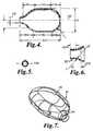
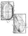
- reservoir 18is generally provided in an exemplary flat, elongated shape as illustrated, which includes shell 26 having a length 100 , a width 102 , and a depth or thickness 106 .
- Reservoir 18is preferably symmetrical or generally symmetrical about its centerline 130 , shown in FIG. 4 .
- Width 102is preferably relatively constant along at least a portion of length 100 and is more preferably relatively constant along at least half of the length 100 of shell 26 , although it is possible that width is constant along less than half of the length 100 of shell 26 .
- a straight portion 114 of one edge of shell 26is located between curved portions 116 and 118 .
- Curved portion 116which is shown on the top edge of shell 26 in FIG. 4 , has a corresponding mirror image curved portion 116 a on the opposite or bottom edge of shell 26 .
- Curved portions 116 and 116 aprovide the outside boundary for a portion of shell 26 that decreases in width from width 102 at straight portions 114 and 114 a down toward a diameter 104 of neck portion 34 , see also the section provided in FIG. 5 depicting the diameter 104 of neck portion 34 .
- the angle of transition from the neck portion 34 to the shell portion 26is approximately angle A.
- FIG. 6further details the transition area 33 from neck portion 34 to shell 26 . As shown, the transition area 33 is provided with an inner radius B and an outer radius C. Additionally, neck portion 34 is defined by a neck portion length 107 and a transition area length 109
- Curved portion 118which is shown on the top edge of shell 26 in FIG. 4 , is a curved edge that extends from straight portion 114 on one edge of shell 26 to the centerline 130 of shell 26 . Curved portion 118 a continues from curved portion 118 around the bottom edge of shell 26 and around to the straight portion 114 a of shell 26 . In this preferred embodiment. length 100 has a greater length than width 102 , and both length 100 and width 102 are greater in length than thickness or depth 106 .
- the thickness 111 of the wall 113 of the shell 26can be appreciated.
- the thickness 111 of the wall 113smoothly blends to the reduced thickness 115 of the neck portion wall 117 , e.g., from a thickness of 0.040 inches in the shell to a thickness of 0.030 inches in the neck portion.
- the thickness 111 of the wall 113is preferably of a substantially consistent thickness, however, the thickness can vary without departing from the spirit or scope of the invention.
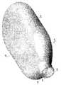
- the contours of the reservoirmay be observed in FIG. 7 .
- Additional featuresmay be added to the reservoir to maintain the integrity of the shell shape.
- the internal or external supportmay be a wire, such as may be constructed of nitinol, and may be shaped to generally match the outer shape of the reservoir.
- the wire or other supportmay be molded as part of the construction of the reservoir after it is formed.
- the wire or other supportmay also extend along the top and/or bottom surfaces of the shell.
- ribs or corrugationscan extend in any desired direction along these surfaces, and can be of varying lengths, depths, and/or widths.
- One or more such ribs or corrugationscan be used, where the ribs on a single shell may be the same or different from each other.
- the ribscan also be useful in the molding manufacture of the part. That is, although the shell can be made by dipping or molding, the addition of one or more ribs will particularly be beneficial in a molding process.
- the ribs or corrugationscan help direct fluid flow and maintain patency.
- length 100 of reservoir 18is about 3.85 inches (9.78 cm), width 102 is about 2.30 inches (5.84 cm), depth 106 is about 1.00 inches (2.54 cm), and neck diameter 104 is about 0.57 inches (1.45 cm).
- the angle of transition Ais about 44 degrees
- the inner radius B of transition area 33is about 0.235 inches (0.61 cm)
- the outer radius C of transition area 33is about 0.229
- the neck portion length 107is about 0.22 inches (0.56 cm)
- the transition area lengthis about 0.22 inches (0.56 cm).
- thickness 111 of the wall 113is about 0.40 inches (1.02 cm) while thickness 115 of the neck portion wall 117 is about 0.3 inches (0.76 cm).
- Reservoir 18 in this preferred embodimentis designed to hold about 85-ml of fluid. However, it is understood that reservoir 18 can be designed to have different dimensions to hold varying capacities of fluid, including capacities of 65-ml and 100-ml, along with other desired volumes.
- the depth of a reservoir of the inventionsuch as depth 106 of reservoir 18 , should be small enough that it can be implanted submuscularly in the lower abdomen of the patient and remain virtually undetectable from outside the patient's body. Further, the length 100 and width 102 are selected to fit into the patient lateral to the midline of the lower abdomen.
- tube 24is shown as having an adapter 36 between neck portion 34 and tube 24 , although tube 24 and adapter 36 are not the only types of devices that can extend from reservoir 18 for fluid communication between reservoir 18 and other adjacent devices or components.
- additional or different adapters or devicesmay be connected directly to one end of neck portion 34 , in which case any tubing used may optionally be attached to the configuration at some other point distal from shell 26 and neck portion 34 .
- the tubepreferably includes an inner fluid passage extending along its length through which fluid can move to and from shell 26 .
- tube 24is a separate component that is sealed to either adapter 36 or neck portion 34 during a molding process as described below.
- tube 24may be molded as part of the neck portion or otherwise fused or bonded directly to neck portion 34 with an appropriate technique.
- an exemplary adapter 36is illustrated with additional detail, which includes a body portion 38 and annular flange 40 .
- annular flange 40increases in diameter from the area of tube 24 toward the end of flange 40 .
- Body portion 38also includes an annular groove 42 that is at the end of flange 40 .
- Body portion 38also includes an annular groove 42 that is at least partially defined by flange 40 and body portion 38 , as illustrated.
- the width of groove 42is preferably designed to accept the free edge of shell 26 . This is, neck portion 34 is designed to fit into annular groove 42 .
- Flange 40is preferably flexible enough that it can conform generally to the outside shape of shell 26 in both its expanded and collapsed conditions.
- the inside surface of flange 40may be adhered or otherwise bonded to the outside surface of shell 26 at or adjacent to neck portion 34 .
- an outside surface of body portion 38may be bonded to an inside surface of annular neck portion 34 in order to secure shell 26 to adapter 34 .
- the inside surface of flange 40may also be adhered to a portion of shell 26 beyond neck portion 34 , such as where the diameter of shell 26 increases and beyond the area where neck portion 34 is positioned within annular flange 40 . It is contemplated that the thickness of the neck portion may vary and/or the width of the annular gap may change along its length.
- any medical grade adhesive, insert molded bonding technology or method, or the likemay be used.
- shell 26When a penile prosthesis device utilizing a reservoir of the invention is implanted in a user, shell 26 may be repeatedly deflated and inflated. During deflation, the shell 26 can collapse inwardly on itself at least slightly, which may also cause it to flex at neck portion 34 (as well as other parts of shell 26 ). Such repeated flexing could cause fatigue at neck portion 34 , which could cause a gradual thinning of the wall and eventual failure (e.g., leakage) between shell 26 and flange 40 .
- flange 40is desirably configured to provide additional support at neck portion 34 while also providing a smooth transition from body portion 38 of adapter 36 to shell 26 and minimizing areas of stress concentration.
- Adapter 36may also include a wide variety of other features, such as the support structures or elements designed to minimize or prevent fluid flow blockage caused by the collapse of an attached reservoir, such as the type described in U.S. patent application Ser. No. 10/957,190, entitled “Fluid Reservoirs for Penile Implant Devices and Method of Manufacturing”, which is also commonly owned by the assignee of the present invention, the entire contents of which are hereby incorporated by reference.
- a lubricity enhancing coatingsuch as a parylene coating or the like may be applied to at least a portion of an inside surface of a reservoir, in U.S. Pat. No. 6,558,315 (Kuyava) and U.S. Patent Application Publication No. 2003/0220540 (Kuyava), both of which are commonly owned by the assignee of the present invention
- a lubricity enhancing coatingsuch as a parylene coating or the like
- a parylene coatingmay be applied by using conventionally known techniques such as vapor deposition or the like, for example.
- a lubricity enhancing coatingcan improve the frictional characteristics of an inside surface of a reservoir and the durability of the reservoir. This can improve reliability of a reservoir by controlling the frictional effects on an inside surface of a reservoir that can result during inflation and deflation of such reservoirs.
- At least some of the components of the penile implant devicescan be treated on their outer surfaces with an antimicrobial agent, including the cylinders, pump and/or reservoir.
- an antimicrobial agentincluding the cylinders, pump and/or reservoir.
- Examples of treating antimicrobial agents on implantable medical devicesare described, for example, in U.S. Pat. No. 6,534,112 (Bouchier et al) and U.S. Patent Application Publication No. 2004/0040500 (Bouchier et al.) both of which are commonly owned by the assignee of the present invention.
- the configurationmay be formed by injection molding, which can use liquid silicone rubber, for example, or by compression molding, which may use gum rubber or high compression rubber, such as silicone, for example.
- Methods of injection moldingmay include the use of a flowable material (e.g., thermoplastic or thermosetting), such as a polymeric material, and a mold.
- the flowable materialis placed at a desired temperature (e.g., by heating) and is injected into a cavity to produce a molded component (here, a fluid reservoir).
- the moldis then opened, optionally after cooling, and the molded component can be removed from the mold and optionally cured.
- a reservoircan be prepared by injection molding methods.
- the reservoirmay be molded to become attached to a tube at the exit orifice of the reservoir shell.
- an elongated tubesuch as tube 24
- the tubecan be positioned onto a mandrel of a mold.
- a relatively spherical, solid mold core pinis also included, which a form of the inside of the reservoir. Outer sections of the mold that define the outer surfaces of the reservoir are then placed around the core pin to thereby create a cavity that is the size and shape of the fluid reservoir.
- the entire moldis then brought to a processing temperature, and then a predetermined amount of a desired material is injected into the mold over the tube and the spherical mode core pin to fill the cavity.
- a predetermined timethe mold is opened and the reservoir with the attached tube is removed from the mold, with the sleeve thereby becoming molded around the outside diameter of the tube as the sleeve body portions of the reservoir are formed.
- the reservoirbeing of a flexible material ca be removed from around the core pin following cooling or curing of the flexible material as necessary. Removal of the reservoir from the core pin can be done by stretching the reservoir material around the core pin.
- water, soap, air, or a combination of thesecan be used to separate the inside surface of the reservoir from the core pin.
- One especially convenient and effective way to introduce any materials such as water, soap and air, to the space between the core pin and the inside of the reservoir,is to inject any one or more of these through the tube connected to the reservoir.
- a plastic fixture or removal toolis placed over the mandrel, which is slightly larger than the shape of the shell, after the silicone has been molded over the mandrel that ‘grabs’ the air-inflated shell. In this way, the fixture with the inflated shell is pulled off the mandrel.
- a reservoirmay be made from liquid silicone rubber, such as a high consistency gum rubber silicone.
- a mold temperaturein the range of 250 deg. F. (121 deg. C.) to 275 deg. F. (135 deg. C.) may be used.
- a molding time of approximately 2.5 minutesmay be used.
- the reservoirmay be made from any other useful, flexible medical or industrial material that is biologically inert and non-reactive with the inflating fluid that will be contained by the reservoir.
- the materialmay be a thermoset or thermoplastic. Specific examples of useful materials can include thermosetting silicone rubber (e.g., polydimethyl siloxane), thermosetting or thermoplastic urethanes, C-flex, santoprene thermoplastics, and the like.
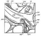
- FIG. 15depicts an example of the reservoir 18 implanted within a patient, tube 24 is also depicted.
- the pertinent anatomyis identified as follows: (1) transverse abdominis muscle 130 ; (2) internal oblique muscle 132 ; (3) orthotopic bladder 134 ; (4) transversalis fascia or abdominal fascia 136 ; (5) rectus abdominis muscle or puborectalis muscle 138 ; (6) external oblique muscle 130 ; (7) linea alba 142 ; (8) pubic ramus 144 ; (9) spermatic cord 146 ; (10) external inguinal ring 148 ; (11) pubic tubercle 150 ; and (12) symphysis pubis 152 .
- FIGS. 9 through 11further illustrate one exemplary embodiment of reservoir 218 of the present invention, which generally includes a shell 226 having an interior space 228 and an opening 230 at one end.
- a neck portion 234extends from shell 226 at opening 230 for connection with a tube, such as tube 224 of prosthesis device 210 .
- Neck portion 234may be directly connected to tube 224 or another component, or an adapter or other device can be used between neck portion 234 and tube 224 to provide a smooth transition between these two components.
- Such an adaptermay be particularly useful, for example, when the neck portion has a different cross-sectional shape (e.g., elliptical) than the cross-sectional shape (e.g., circular) of the tube to which the neck portion is attached.
- any additional devices or adapters that are provided between tube 224 and neck portion 234may be directly molded to one or both components, or may be adhered or otherwise attached to one or both components to prevent fluid leakage and allow for smooth fluid flow. In any case, the transitions between tube 224 and neck portion 234 should not inhibit the flow of fluid to and from interior space 228 of reservoir 218 .
- Reservoir 218is generally provided in a relatively flat, circular shape as illustrated, which includes shell 226 that is shaped as a relatively flat disc. Reservoir 218 is preferably symmetrical or generally symmetrical about its centerline 310 , with shell 226 having a diameter 300 and a depth or thickness 302 .
- Neck portion 234extends from shell 226 at one end, and is generally oval or elliptical in shape. Neck portion 234 has a width 304 and a depth 312 that is equal to or at least slightly smaller than depth or thickness 302 of shell 226 .
- neck portion 234has a material thickness 306 . The material from which the remainder of reservoir 218 is made may be the same or a different thickness than material thickness 306 .
- a small curved portion 314 that curves in the opposite direction of the outer periphery of shell 226can be provided in the transition area between shell 226 and neck portion 234 .
- Shell 226also includes a slight curvature relative to the neck portion 234 or as compared to a planar device, which is most visible in FIG. 11 .
- This curvaturehas a radius 308 when viewed from the bottom or neck area 234 of shell 226 .
- the center of a circle that defines the radius 308would include an axis that extends in the same direction as centerline 310 .
- neck portion 234is not shown as following the same curvature as shell 226 , it is understood that neck portion 234 may also have a radius that is similar to radius 308 (i.e., neck portion 234 may follow the same curvature as shell 226 ), or neck portion 234 may alternatively have a radius that is smaller or larger than radius 308 .
- shell 226includes a top surface 320 and an opposite bottom surface 322 that is spaced from top surface 320 by a distance equal to depth 302 .
- a curved edge surface 324extends between top surface 320 and bottom surface 322 along most of the peripheral edge of shell 226 , except in the area of opening 230 .
- Top surface 320is preferably a slightly curved surface that is generally parallel to bottom surface 322 , which is a surface that has a similar curve. However, it is possible that these surfaces 320 , 322 are angled relative to each other such that depth 302 varies within the interior portion of shell 226 .
- the curved edge surface 324 between top surface 320 and bottom surface 322can be provided with a material thickness that is greater than the material thickness of either or both of top and bottom surfaces 320 , 322 .
- the material thickness of curved edge surface 324can be less than or the same as the material thickness of top and bottom surfaces 320 , 322 .
- curved edge surface 324is shaped and sized to promote the integrity of the shape of shell 226 . This feature is particularly advantageous to maintain the shape of reservoir 218 when the reservoir is subjected to external pressures cause by the patient's internal organs and bodily fluids after it is implanted in the body.
- diameter 300 of shell 226is about 3.30 inches (8.38 cm)
- thickness 102is about 0.50 inches (1.27 cm)
- width 304 of neck portion 234is about 0.75 inches (1.91 cm).
- the thickness of top and bottom surfaces 320 , 322is about 0.025 inches (0.064 cm) and thickness 306 of neck portion 234 is about 0.025 inches (0.064 cm).
- the internal volume of reservoir 218 in this embodimentis about 3.63 in 3 (59.49 cm 3 ).
- reservoir 218can be designed to have different wall thickness and overall dimensions to hold varying capacities of fluid, including capacities of 65-ml and 100-ml, along with other desired volumes.
- the depth of a reservoir of the inventionshould be small enough that the reservoir can be implanted submuscularly in the lower abdomen of the patient and remain virtually undetectable from outside the patient's body.
- the diameter 300is also selected to fit into the patient lateral to the midline of the lower abdomen.
- the curvature of shell 226 of this exemplary embodimenthas a radius 308 of about 6 inches (15.24 cm); however, radius 308 can be chosen to be any appropriate size that allows placement of shell 226 submuscularly in the lower abdomen.
- FIGS. 12 through 14further illustrate another exemplary embodiment of reservoir 418 of the present invention, which generally includes a shell 426 having an interior space 428 and an opening 430 at one end.
- a neck portion 434extends from shell 426 at opening 430 for connection with a tube, such as tube 24 of prosthesis device 10 .
- Neck portion 434may be directly connected to tube 24 or another component in a prosthesis device, or an adapter or other device can be used between neck portion 434 and tube 24 to provide a smooth transition between these two components.
- Such an adaptermay be particularly useful, for example, when the neck portion has a different cross-sectional shape (e.g., elliptical) than the cross-sectional shape (e.g., circular) of the tube to which the neck portion is attached.
- any additional devices or adapters that are provided between tube 24 and neck portion 434may be directly molded to one or both components, or may be adhered or otherwise attached to one or both components to prevent fluid leakage and allow for smooth fluid flow. In any case, the transitions between tube 24 and neck portion 434 should not inhibit the flow of fluid to and from interior space 428 of reservoir 418 .
- Reservoir 418is generally provided in a relatively flat, oval-like shape as illustrated, which includes shell 426 having a height 450 , a width 452 , and a depth or thickness 454 . Height 450 is shorter than width 452 , thereby creating the non-circular or oval-like shape of shell 426 .
- Reservoir 418is preferably symmetrical or generally symmetrical about a centerline 456 that extends from the shell throughout the center of neck portion 434 , as shown in FIG. 13 .
- Shell 426(not including neck portion 434 ) is preferably symmetrical or generally symmetrical about a centerline 458 that is perpendicular to centerline 456 .
- Neck portion 434extends from shell 426 at one end, and is generally oval or elliptical in shape.
- the outer periphery of reservoir 418includes shell 426 having two curved edge portions 460 and 462 , where edge portion 460 extends from centerline 456 at the top of shell 426 around the left side of shell 426 to neck portion 434 , and edge portion 462 extends from centerline 456 at the top of shell 426 around the right side of shell 426 to neck portion 434 .
- Curved edge portions 460 , 462provide the outside boundary for a portion of shell 426 that decreases in height 450 when moving away from centerline 456 , and which also decreases in width 452 when moving away from centerline 458 .
- a small curved portion 464 that curves in the opposite direction of the outer periphery of shell 426can be provided in the transition area between shell 426 and neck portion 434 .
- Neck portion 434has a width 436 and a depth 438 that is equal to or at least slightly smaller than depth or thickness 454 of shell 426 .
- neck portion 434has a material thickness 440 .
- the material from which the remainder of reservoir 418 is mademay be the same or a different thickness than material thickness 440 .
- Shell 426also includes a slight curvature relative to the neck portion 434 or as compared to a planar device, which is most visible in FIG. 14 .
- This curvaturehas a radius 442 when viewed from the bottom or neck area 434 of shell 426 .
- neck portion 434is not shown as following the same curvature as shell 426 , it is understood that neck portion 434 may also have a radius that is similar to radius 442 (i.e., neck portion 434 may follow the same curvature as shell 426 ), or neck portion 434 may alternatively have a radius that is smaller or larger than radius 442 .
- shell 426includes a top surface 444 and an opposite bottom surface 446 that is spaced from top surface 444 by a distance equal to depth 454 .
- a curved edge surface 448extends between top surface 444 and bottom surface 446 along most of the peripheral edge of shell 426 , except in the area of opening 430 .
- Top surface 444is preferably a slightly curved surface that is generally parallel to bottom surface 446 , which is a surface that has a similar curve, although it is possible that these surfaces 444 , 446 are angled relative to each other such that depth 454 varies within the interior portion of shell 426 . It is also possible that surfaces 444 , 446 have different curvatures relative to each other or that one of the surfaces is generally straight. Surfaces 444 , 446 may also curve in opposite directions from each other.
- the curved edge surface 448 between top surface 444 and bottom surface 446can be provided with a material thickness that is greater than the material thickness of either or both of top and bottom surfaces 444 , 446 .
- the material thickness of curved edge surface 448can be less than or the same as the material thickness of top and bottom surfaces 444 , 446 .
- curved edge surface 248is shaped and sized to promote the integrity of the shape of shell 426 . This feature is particularly advantageous to maintain the shape of reservoir 418 when the reservoir is subjected to external pressures cause by the patient's internal organs and bodily fluids after it is implanted in the body.
- edge surface 448could be more square or angular in shape, where it is contemplated that the outside surface of edge surface 448 can be more squared than the portion of surface opposite edge surface that faces the inside of the shell, which may be curved, for example.
- width 452 of shell 426is about 4.50 inches (11.43 cm)
- height 450is about 2.50 inches (6.35 cm)
- depth 454is about 0.50 inches (1.27 cm)
- width 436 of neck portion 434is about 1.00 inches (2.54 cm).
- the thickness of top and bottom surfaces 444 , 446is about 0.025 inches (0.064 cm) and thickness 440 of neck portion 434 is about 0.025 inches (0.064 cm).
- the internal volume of reservoir 418 in this embodimentis about 3.80 in 3 (62.27 cm 3 ).
- reservoir 418can be designed to have different dimensions to hold varying capacities of fluid, including capacities of 65-ml and 100-ml, along with other desired volumes.
- the depth of a reservoir of the inventionshould be small enough that the reservoir can be implanted submuscularly in the lower abdomen of the patient and remain virtually undetectable from outside the patient's body.
- the curvature of shell 426 of this exemplary embodimenthas a radius 442 of about 6 inches (15.24 cm); however, radius 442 can be chosen to be any appropriate size that allows placement of shell 426 submuscularly in the lower abdomen.
- FIGS. 16 through 18further illustrate one exemplary embodiment of reservoir 518 of the present invention, which generally includes a shell 526 having an interior space 528 and an opening 530 at one end.
- a neck portion 534extends from shell 526 at opening 530 for connection with a tube, such as tube 24 of prosthesis device 10 .
- Neck portion 534may be directly connected to tube 24 or another component, or an adapter or other device can be used between neck portion 534 and tube 24 to provide a smooth transition between these two components.
- Any additional devices or adapters that are provided between tube 24 and neck portion 534may be directly molded to one or both components, or may be adhered or otherwise attached to one or both components to prevent fluid leakage and allow for smooth fluid flow. In any case, the transitions between tube 24 and neck portion 534 should not inhibit the flow of fluid to and from interior space 528 of reservoir 518 .
- reservoir 518is generally provided in an exemplary flat, elongated shape as illustrated, which includes shell 526 having a length 600 , a width 602 , and a depth or thickness 606 .
- Reservoir 518is preferably symmetrical or generally symmetrical about its centerline 630 , shown in FIG. 17 .
- Width 602is preferably relatively constant along at least a portion of length 600 , and is more preferably relatively constant along at least half of the length 600 of shell 526 , although it is possible that the width 602 is constant along less than half of the length 600 of shell 526 .
- a straight portion 614 of one edge of shell 526is located between curved portions 616 and 618 .
- Curved portion 616which is shown on the top edge of shell 526 in FIG. 17 , has a corresponding (i.e., mirror image) curved portion 616 a on the opposite or bottom edge of shell 526 .
- Curved portions 616 and 616 aprovide the outside boundary for a portion of shell 526 that decreases in width from width 602 at straight portions 614 and 614 a down toward a diameter 604 of neck portion 534 .
- a small curved portion that curves in the opposite direction of portion 616can be provided in the transition area between portion 616 and neck portion 534 .
- Curved portion 618which is shown on the top edge of shell 526 in FIG.
- length 600has a greater length than width 602 , and both length 600 and width 602 are greater in length than thickness or depth 606 .
- Shell 526includes a top surface 620 and an opposite bottom surface 622 that is spaced from top surface 620 by a distance equal to depth 606 .
- a curved edge surface 624extends between top surface 620 and bottom surface 622 along most of the peripheral edge of shell 526 , except in the area of opening 630 .
- Top surface 620is preferably a planar surface that is generally parallel to bottom surface 622 , although it is possible that these surfaces 620 , 622 are angled relative to each other such that depth 606 varies within the interior portion of shell 526 .
- Top surface 620 and bottom surface 622have a thickness 608
- neck portion 534has a thickness 612
- curved edge surface 624has a thickness 610 .
- Thickness 608is preferably generally the same as or slightly greater than thickness 612 .
- Thickness 610is preferably greater than thicknesses 608 and 612 to promote the integrity of the shape of shell 526 .
- thickness 610can be less than or the same as thicknesses 608 and 612 .
- This featureis particularly advantageous to maintain the shape of reservoir 518 when the reservoir is subjected to external pressures cause by the patient's internal organs and bodily fluids after it is implanted in the body. More preferably, thickness 610 is about twice as large as thicknesses 608 and 612 .
- the increase in thickness from either of the top and bottom surfaces 620 , 622 to curved edge surface 624is preferably a gradual increase in the form of a tapered change in thickness between the various surfaces of reservoir 518 .
- An additional way to maintain the integrity of the shell shapeis to provide an internal or external support material that is attached to or otherwise situated relative to the shell.
- a wiresuch as may be constructed of nitinol, may be shaped to generally match the outer shape of the reservoir.
- the wire or other supportmay be molded as part of the construction of the reservoir, or may alternatively be inserted or otherwise attached to the reservoir after it is formed.
- the wire or other supportmay also extend along the top and/or bottom surfaces of the shell.
- ribs or corrugationscan extend in any desired direction along these surfaces, and can be of varying lengths, depths, and/or widths.
- One or more such ribs or corrugationscan be used, where the ribs on a single shell may be the same or different from each other.
- the ribscan also be useful in the molding manufacture of the part. That is, although the shell can be made by either dipping or molding, the addition of one or more ribs will particularly be beneficial in a molding process.
- the ribs or corrugationscan help direct fluid flow and maintain patency.
- length 600 of reservoir 518is about 3.75 inches (9.53 cm), width 602 is about 2.25 inches (5.72 cm), depth 606 is about 0.75 inches (1.91 cm), and neck diameter 604 is about 0.50 inches (1.27 cm).
- thickness 610 of curved portion 624is about 0.080 inches (0.203 cm)
- thickness 608 of top and bottom surfaces 620 and 622is about 0.040 inches (0.102 cm)
- thickness 612 of neck 534is about 0.040 inches (0.102 cm).
- the internal volume of reservoir 518 in this embodimentis about 3.92 in 3 (64.24 cm 3 ).
- reservoir 518can be designed to have different dimensions to hold varying capacities of fluid, including capacities of 65-ml and 100-ml, along with other desired volumes.
- the depth of a reservoir of the inventionsuch as depth 606 of reservoir 518 , should be small enough that it can be implanted submuscularly in the lower abdomen of the patient and remain virtually undetectable from outside the patient's body.
- the length 600 and width 602are selected to fit into the patient lateral to the midline of the lower abdomen.
Landscapes
- Health & Medical Sciences (AREA)
- Reproductive Health (AREA)
- Cardiology (AREA)
- Oral & Maxillofacial Surgery (AREA)
- Transplantation (AREA)
- Engineering & Computer Science (AREA)
- Biomedical Technology (AREA)
- Heart & Thoracic Surgery (AREA)
- Vascular Medicine (AREA)
- Life Sciences & Earth Sciences (AREA)
- Animal Behavior & Ethology (AREA)
- General Health & Medical Sciences (AREA)
- Public Health (AREA)
- Veterinary Medicine (AREA)
- Prostheses (AREA)
Abstract
Description
Claims (25)
Priority Applications (1)
| Application Number | Priority Date | Filing Date | Title |
|---|---|---|---|
| US11/279,035US7946975B2 (en) | 2005-04-08 | 2006-04-07 | Fluid reservoir for penile implant devices |
Applications Claiming Priority (3)
| Application Number | Priority Date | Filing Date | Title |
|---|---|---|---|
| US66967305P | 2005-04-08 | 2005-04-08 | |
| US66942705P | 2005-04-08 | 2005-04-08 | |
| US11/279,035US7946975B2 (en) | 2005-04-08 | 2006-04-07 | Fluid reservoir for penile implant devices |
Publications (2)
| Publication Number | Publication Date |
|---|---|
| US20060235267A1 US20060235267A1 (en) | 2006-10-19 |
| US7946975B2true US7946975B2 (en) | 2011-05-24 |
Family
ID=37109433
Family Applications (1)
| Application Number | Title | Priority Date | Filing Date |
|---|---|---|---|
| US11/279,035Active2030-02-21US7946975B2 (en) | 2005-04-08 | 2006-04-07 | Fluid reservoir for penile implant devices |
Country Status (1)
| Country | Link |
|---|---|
| US (1) | US7946975B2 (en) |
Cited By (12)
| Publication number | Priority date | Publication date | Assignee | Title |
|---|---|---|---|---|
| US8491462B2 (en) | 2011-08-08 | 2013-07-23 | Coloplast A/S | Penile prosthetic deflation assembly having a palpatable activation surface |
| US8523761B2 (en) | 2011-08-24 | 2013-09-03 | Coloplast A/S | Penile prosthetic reservoir |
| US8684910B2 (en) | 2011-08-08 | 2014-04-01 | Coloplast A/S | Method of implanting a penile prosthetic deflation assembly having a palpatable activation surface |
| US8939889B1 (en) | 2013-08-22 | 2015-01-27 | Coloplast A/S | Pump bulb for an implantable penile prosthetic |
| US9308088B2 (en) | 2011-08-08 | 2016-04-12 | Coloplast A/S | Artificial urinary sphincter system deflation assembly |
| US9554937B2 (en) | 2014-06-16 | 2017-01-31 | Coloplast A/S | Penile prosthetic pump having an inlet valve with a lockout flange |
| US9649217B2 (en) | 2014-07-08 | 2017-05-16 | Coloplast A/S | Implantable penile prosthetic lockout valve assembly |
| US9724182B2 (en) | 2014-10-17 | 2017-08-08 | Coloplast A/S | Connector cuff |
| US9964850B2 (en) | 2014-07-31 | 2018-05-08 | Taiwan Semiconductor Manufacturing Company, Ltd. | Method to mitigate defect printability for ID pattern |
| US9987136B2 (en) | 2016-09-09 | 2018-06-05 | Coloplast A/S | Penile prosthetic pump with an inflation assembly including a rotary valve |
| US11311382B2 (en) | 2018-11-27 | 2022-04-26 | Boston Scientific Scimed, Inc. | Pump assembly having a push valve for a penile prosthesis |
| US12083016B2 (en) | 2020-10-15 | 2024-09-10 | Boston Scientific Scimed, Inc. | Pump assembly for a penile prosthesis |
Families Citing this family (14)
| Publication number | Priority date | Publication date | Assignee | Title |
|---|---|---|---|---|
| US8911350B2 (en) | 2007-10-23 | 2014-12-16 | Ams Research Corporation | Malleable prosthesis with enhanced concealability |
| US8114011B2 (en) | 2007-10-23 | 2012-02-14 | Ams Research Corporation | Corrugated inflatable penile prosthesis cylinder |
| US8123674B2 (en)* | 2007-11-12 | 2012-02-28 | Ams Research Corporation | Corrugated expansion-constraining sleeve for an inflatable penile prosthesis cylinder |
| WO2009124554A1 (en)* | 2008-04-07 | 2009-10-15 | Coloplast A/S | Implantable fluid devices |
| US7833149B2 (en)* | 2008-04-29 | 2010-11-16 | Coloplast A/S | Low profile rear tip for inflatable penile prostheses |
| US8241203B2 (en)* | 2010-02-12 | 2012-08-14 | Fogarty Terence M | Inflatable penile prosthesis with spool valve |
| US9161751B2 (en) | 2010-12-02 | 2015-10-20 | Coloplast A/S | Suture system and assembly |
| US9474610B2 (en) | 2010-12-21 | 2016-10-25 | Boston Scientific Scimed, Inc. | Adjustable length rear tip extender for penile prosthesis |
| US8568428B2 (en) | 2011-01-05 | 2013-10-29 | Coloplast A/S | Suture system and assembly including a tubular leader having a clasp |
| US9220495B2 (en) | 2011-02-10 | 2015-12-29 | Coloplast A/S | Suture system and assembly including a suture clip |
| US8591528B2 (en) | 2011-02-24 | 2013-11-26 | Coloplast A/S | Suture system and assembly including a suture cap formed around a tubular sleeve |
| US9084678B2 (en) | 2012-01-20 | 2015-07-21 | Ams Research Corporation | Automated implantable penile prosthesis pump system |
| US10765520B2 (en) | 2017-04-05 | 2020-09-08 | Coloplast A/S | Penile implant with a length-adjustable tube |
| US20200397583A1 (en)* | 2019-06-19 | 2020-12-24 | Boston Scientific Scimed, Inc. | Attachment plates and implants for penile construction |
Citations (148)
| Publication number | Priority date | Publication date | Assignee | Title |
|---|---|---|---|---|
| US988120A (en) | 1910-02-15 | 1911-03-28 | John B Lott | Dilator. |
| US1863057A (en) | 1930-03-03 | 1932-06-14 | George A Innes | Surgical drain |
| US2586575A (en) | 1949-05-31 | 1952-02-19 | Pyrene Mfg Co | Fire-extinguishing apparatus |
| US2786718A (en) | 1955-07-11 | 1957-03-26 | William F Middlestadt | Dispensing attachment for a liquid container |
| US3228731A (en) | 1962-04-23 | 1966-01-11 | Bendix Westinghouse Automotive | Variable pressure ratio valve |
| US3312215A (en) | 1963-08-02 | 1967-04-04 | Max N Silber | Uterocervical cannula |
| US3344791A (en) | 1965-02-12 | 1967-10-03 | John W Foderick | Bulbous urinary catheter with axial extension means |
| US3397699A (en) | 1966-05-05 | 1968-08-20 | Gerald C. Kohl | Retaining catheter having resiliently biased wing flanges |
| US3503400A (en) | 1967-07-12 | 1970-03-31 | Sven M Osthagen | Urethral valve |
| US3510029A (en) | 1968-03-11 | 1970-05-05 | Sterling Drug Inc | Over-cap with molded trigger and air seal cap for the spray orifice |
| US3642004A (en) | 1970-01-05 | 1972-02-15 | Life Support Equipment Corp | Urethral valve |
| US3731670A (en) | 1971-05-03 | 1973-05-08 | David Roy Pressman | Corporeal fluid control using bistable magnetic duct valve |
| US3797478A (en) | 1972-07-11 | 1974-03-19 | M Walsh | Multi-functional valve for use in the urethra |
| US3812841A (en) | 1972-08-21 | 1974-05-28 | L Isaacson | Urethra magnetic valve structure |
| US3853122A (en) | 1973-10-12 | 1974-12-10 | B Strauch | Method and device for achieving a penile erection |
| US3954102A (en)* | 1974-07-19 | 1976-05-04 | American Medical Systems, Inc. | Penile erection system and methods of implanting and using same |
| US4009711A (en) | 1976-03-17 | 1977-03-01 | Uson Aurelio C | Penile prosthesis for the management of erectile impotence |
| DE2537506A1 (en) | 1975-08-22 | 1977-03-03 | Hennig Gerhard | Bladder outlet valve for incontinent people - has magnet cone embedded in magnet ring seat with powerful external opening magnet |
| US4201202A (en) | 1978-09-25 | 1980-05-06 | Medical Engineering Corp. | Penile implant |
| US4204530A (en) | 1979-03-29 | 1980-05-27 | Medical Engineering Corp. | Sleeve implant |
| US4222377A (en) | 1977-06-27 | 1980-09-16 | American Medical Systems, Inc. | Pressure regulated artificial sphincter systems |
| US4224934A (en) | 1979-04-11 | 1980-09-30 | American Medical Systems, Inc. | Medical prosthetic pull valve and system for using same |
| US4235227A (en) | 1978-11-08 | 1980-11-25 | Hideo Yamanaka | Artificial corpus cavernosum device |
| US4256093A (en) | 1978-10-12 | 1981-03-17 | The United States Of America As Represented By The Administrator Of The National Aeronautics And Space Administration | Prosthetic urinary sphincter |
| US4267829A (en) | 1979-04-11 | 1981-05-19 | American Medical Systems, Inc. | Penile prosthesis |
| US4318396A (en) | 1980-05-15 | 1982-03-09 | Medical Engineering Corporation | Penile prosthesis |
| US4342308A (en) | 1980-10-02 | 1982-08-03 | Medical Engineering Corporation | Penile erectile system |
| US4344434A (en) | 1981-06-01 | 1982-08-17 | Santa Barbara Medical Foundation Clinic | Ileostomy appliance and method for implanting the same |
| US4353360A (en) | 1980-10-31 | 1982-10-12 | Medical Engineering Corporation | Penile erectile system |
| US4360010A (en) | 1980-05-15 | 1982-11-23 | Medical Engineering Corporation | Penile prosthesis |
| US4364379A (en) | 1980-05-15 | 1982-12-21 | Finney Roy P | Penile erectile system |
| US4369771A (en) | 1981-09-24 | 1983-01-25 | Medical Engineering Corporation | Penile erectile system |
| US4378792A (en) | 1980-05-15 | 1983-04-05 | Medical Engineering Corporation | Penile prosthesis |
| US4399812A (en) | 1981-12-31 | 1983-08-23 | Whitehead Edgar D | Penile prosthetic device |
| US4399811A (en) | 1981-08-04 | 1983-08-23 | Medical Engineering Corporation | Implantable penile erectile system |
| US4404968A (en) | 1982-04-07 | 1983-09-20 | Evans Sr Alvin S | Pump and valve assembly for penile implant |
| US4407278A (en) | 1981-05-15 | 1983-10-04 | American Medical Systems, Inc. | Penile prosthesis with improved fluid control |
| US4412530A (en) | 1981-09-21 | 1983-11-01 | American Medical Systems, Inc. | Dual-mode valve pressure regulating system |
| US4424807A (en) | 1981-10-20 | 1984-01-10 | Evans Sr Alvin S | Penile implant |
| US4437457A (en) | 1982-04-27 | 1984-03-20 | Medical Engineering Corporation | Artificial sphincter with improved pressure control valve |
| US4441491A (en) | 1982-08-13 | 1984-04-10 | Evans Sr Alvin S | Pressure relief valve system for penile implant device |
| US4449520A (en) | 1982-09-02 | 1984-05-22 | Palomar Juan M | Penile prosthesis device |
| US4453536A (en) | 1980-11-03 | 1984-06-12 | Abild Robert N | Body channel occluder |
| US4457335A (en) | 1981-09-24 | 1984-07-03 | Medical Engineering Corporation | Penile erectile system |
| US4489732A (en) | 1982-09-20 | 1984-12-25 | Hasson Harrith M | Gynecological instrument |
| US4523584A (en) | 1983-03-04 | 1985-06-18 | Medical Engineering Corporation | Penile erectile system |
| US4532920A (en) | 1980-05-15 | 1985-08-06 | Medical Engineering Corporation | Penile implant |
| US4537183A (en) | 1983-04-08 | 1985-08-27 | Mentor Corporation | Connector device for connecting elastic tubing of an implantable device |
| US4550719A (en) | 1981-08-04 | 1985-11-05 | Medical Engineering Corporation | Implantable penile erectile system |
| US4550720A (en) | 1983-11-15 | 1985-11-05 | Medical Engineering Corporation | Capacitance device for medical implant |
| US4553959A (en) | 1982-01-27 | 1985-11-19 | The Victoria University Of Manchester | Urethral catheter |
| US4558693A (en) | 1983-08-29 | 1985-12-17 | Harvey Lash | Penile implant |
| US4559931A (en) | 1983-03-21 | 1985-12-24 | Fischell Robert | Manually actuated fully implantable penile erection device |
| US4566446A (en) | 1983-04-08 | 1986-01-28 | Mentor Corporation | Penile prosthesis device |
| US4571241A (en) | 1983-12-16 | 1986-02-18 | Christopher T Graham | Urinary catheter with collapsible urethral tube |
| US4572168A (en) | 1983-12-20 | 1986-02-25 | Fischell Robert | Fully implantable vapor pressure actuated penile erection device and method |
| US4574792A (en) | 1981-09-24 | 1986-03-11 | Medical Engineering Corporation | Penile erectile system |
| US4587954A (en) | 1983-12-29 | 1986-05-13 | Habley Medical Technology Corporation | Elastomeric prosthetic sphincter |
| US4590927A (en) | 1985-02-25 | 1986-05-27 | American Medical Systems, Inc. | Unitary, inflatable penile prosthesis system |
| US4596242A (en)* | 1983-08-26 | 1986-06-24 | Fischell Robert | Method and apparatus for achieving penile erection in a human male |
| US4602625A (en) | 1983-03-04 | 1986-07-29 | Medical Engineering Corporation | Penile erectile system |
| US4604994A (en) | 1985-06-24 | 1986-08-12 | Repro-Med Systems, Inc. | Implantable medical prosthesis for obviating male impotency |
| US4611584A (en) | 1980-05-15 | 1986-09-16 | Medical Engineering Corp. | Expandable penile implant |
| US4622958A (en) | 1984-12-12 | 1986-11-18 | Medical Engineering Corporation | Penile implant with accumulator |
| US4632435A (en) | 1984-12-27 | 1986-12-30 | American Medical Systems, Inc. | Tubing connector system |
| US4651721A (en) | 1985-04-10 | 1987-03-24 | American Medical Systems, Inc. | Penile prosthesis system |
| US4653485A (en) | 1984-07-23 | 1987-03-31 | Fishell Robert E | Penile erection device stiffener cylinder and implantation method |
| US4664100A (en) | 1984-11-19 | 1987-05-12 | Rudloff David A C | Penile implant |
| US4665903A (en) | 1981-12-31 | 1987-05-19 | Whitehead Edgar D | Penile prosthetic device |
| US4671261A (en)* | 1986-01-24 | 1987-06-09 | Fischell Robert | Penile erection device with valving in the penile cylinder |
| US4682583A (en) | 1984-04-13 | 1987-07-28 | Burton John H | Inflatable artificial sphincter |
| US4682589A (en) | 1980-05-15 | 1987-07-28 | Medical Engineering Corporation | Penile prosthesis |
| US4710169A (en) | 1983-12-16 | 1987-12-01 | Christopher T Graham | Urinary catheter with collapsible urethral tube |
| US4718410A (en) | 1978-08-02 | 1988-01-12 | Hakky Said I | Surgical implants |
| US4724830A (en) | 1986-02-24 | 1988-02-16 | Fischell Robert | Flow control device for an implantable prosthesis |
| US4726360A (en) | 1986-07-17 | 1988-02-23 | Medical Engineering Corporation | Penile prosthesis |
| US4730607A (en) | 1984-08-20 | 1988-03-15 | Fischell Robert | Stiffener cylinder for an inflatable penile erection device |
| US4766889A (en) | 1986-06-26 | 1988-08-30 | Medical Engineering Corporation | Infusion erectile system |
| US4773403A (en) | 1987-08-17 | 1988-09-27 | Medical Engineering Corporation | Penile prosthesis |
| US4782826A (en) | 1987-05-21 | 1988-11-08 | Mentor Corporation | Penile prosthesis |
| US4790298A (en) | 1987-08-05 | 1988-12-13 | Medical Engineering Corporation | Penile prosthesis and method |
| US4791917A (en) | 1981-10-22 | 1988-12-20 | Medical Engineering Corporation | Penile prosthesis |
| US4807608A (en) | 1987-07-22 | 1989-02-28 | American Medical Systems | Mechanical penile prosthesis |
| US4829990A (en) | 1987-06-25 | 1989-05-16 | Thueroff Joachim | Implantable hydraulic penile erector |
| US4829991A (en) | 1987-01-06 | 1989-05-16 | Medical Engineering Corp. | Method and device for stimulating an erection |
| US4850963A (en) | 1986-06-11 | 1989-07-25 | Utah Bioresearch, Inc. | Apparatus and methods for achieving urinary continence |
| US4881530A (en)* | 1988-01-19 | 1989-11-21 | Medical Engineering Corporation | Penile prosthesis |
| US4895139A (en) | 1988-08-29 | 1990-01-23 | American Medical Systems, Inc. | Inflatable penile prosthesis with bend release valve |
| US4917110A (en) | 1986-07-17 | 1990-04-17 | Medical Engineering Corporation | Penile prosthesis |
| US4932938A (en) | 1989-05-05 | 1990-06-12 | Medical Engineering Corporation | Urethral indwelling catheter with incontinence control |
| US4944732A (en) | 1988-08-15 | 1990-07-31 | Sandoz Nutrition Corporation | Gastrostomy feeding port |
| US4958630A (en) | 1989-10-06 | 1990-09-25 | Advanced Surgical Intervention, Inc. | Method and apparatus for treating impotence |
| US4968294A (en) | 1989-02-09 | 1990-11-06 | Salama Fouad A | Urinary control valve and method of using same |
| US4988357A (en) | 1983-12-08 | 1991-01-29 | Industriestrasse | Penis prosthesis |
| US5010882A (en) | 1989-11-13 | 1991-04-30 | American Medical Systems, Inc. | Implantable penile prosthesis |
| US5030199A (en) | 1989-12-11 | 1991-07-09 | Medical Engineering Corporation | Female incontinence control device with magnetically operable valve and method |
| US5034009A (en) | 1987-11-03 | 1991-07-23 | Mouchel Jack A P | Instrument for locating the proximal end of the urethra |
| US5041092A (en) | 1989-08-29 | 1991-08-20 | Medical Engineering Corporation | Urethral indwelling catheter with magnetically controlled drainage valve and method |
| US5048511A (en) | 1989-10-06 | 1991-09-17 | Advanced Surgical Intervention, Inc. | Method and apparatus for treating impotence |
| US5048510A (en) | 1988-08-29 | 1991-09-17 | American Medical Systems, Inc. | Inflatable penile prosthesis with satellite reservoir |
| US5052383A (en) | 1989-03-21 | 1991-10-01 | La Spirotechnique Industrielle Et Commerciale | Device for supplying breathing gas to a diver |
| US5062417A (en) | 1990-10-10 | 1991-11-05 | Mentor Corporation | Prosthesis with improved pump |
| US5062416A (en) | 1988-12-01 | 1991-11-05 | Stucks Albert A | Penile erection system |
| US5063914A (en) | 1990-05-30 | 1991-11-12 | Mentor Corporation | Penile prosthesis |
| US5067485A (en) | 1990-05-14 | 1991-11-26 | Mentor Corporation | Corpus cavernosum implant device |
| US5074849A (en) | 1990-01-22 | 1991-12-24 | Sachse Hans Ernst | Ureter drainage tube with fixable auxiliary tube |
| US5085650A (en) | 1989-10-20 | 1992-02-04 | Giglio Frank A | Gynecological urethral suppository |
| US5088980A (en) | 1990-05-31 | 1992-02-18 | The United States Of America As Represented By The Department Of Health And Human Services | Intra-urethral valve with integral spring |
| US5090424A (en) | 1990-12-31 | 1992-02-25 | Uromed Corporation | Conformable urethral plug |
| US5101813A (en) | 1986-07-17 | 1992-04-07 | Medical Engineering Corporation | Penile erectile system and method for sterilization |
| US5112295A (en) | 1990-04-20 | 1992-05-12 | Zinner Norman R | Penile prosthesis and method |
| US5114398A (en) | 1990-02-27 | 1992-05-19 | Medical Engineering Corporation | Female incontinence control device with mechanically operable valve |
| US5129880A (en) | 1990-02-09 | 1992-07-14 | Hans Grundei | Penis prosthesis |
| US5131906A (en) | 1988-10-20 | 1992-07-21 | Chen Fusen H | Incontinence device |
| US5141509A (en) | 1991-08-06 | 1992-08-25 | American Medical Systems, Inc. | Penile prosthesis having means for preventing spontaneous inflation |
| US5158111A (en) | 1991-12-13 | 1992-10-27 | Quality Machine & Supply, Inc. | Pilot valve for pneumatic control systems with improved poppet |
| US5167611A (en) | 1991-07-22 | 1992-12-01 | Mentor Corporation | Penile implant with lengthening cylinder |
| US5171272A (en) | 1990-09-24 | 1992-12-15 | American Medical Systems, Inc. | Fluid pump for penile prosthesis |
| US5186180A (en) | 1989-08-07 | 1993-02-16 | Bellas Gabriel A S | Intra-vaginal prolapse diagnostic instrument |
| US5250020A (en) | 1991-09-12 | 1993-10-05 | Mentor Corporation | Unitary inflatable penile prosthesis |
| US5263981A (en) | 1992-04-24 | 1993-11-23 | American Medical Systems, Inc. | Implantable penile prosthesis |
| US5328293A (en) | 1990-12-20 | 1994-07-12 | Keefe-Dickson Corporation Inc. | Tactile tile |
| US5344388A (en) | 1991-05-01 | 1994-09-06 | Maxwell G Patrick | Textured surface prosthetic device |
| US5433694A (en) | 1993-09-28 | 1995-07-18 | Lim; Seung-Hyun | Penile elevator |
| EP0682923A1 (en) | 1994-05-19 | 1995-11-22 | George Patrick Maxwell | Textured surface penile prosthetic device |
| US5518499A (en) | 1995-06-06 | 1996-05-21 | Aghr; Arif H. | Intracavernous vasoactive pharmacological pump |
| US5595331A (en) | 1994-08-30 | 1997-01-21 | Leistner; Corinna | Clamping coat hanger for garments |
| US5678768A (en) | 1995-03-15 | 1997-10-21 | H.D. Hudson Manufacturing Company | Shroud with cartridge based shut-off for sprayers |
| US5851176A (en) | 1996-07-29 | 1998-12-22 | Mentor Corporation | Pressure-responsive lockout valve and method of use |
| US5893826A (en) | 1997-08-14 | 1999-04-13 | Salama; Fouad A. | Artificial sphincter urinary control system |
| US5895424A (en) | 1996-11-12 | 1999-04-20 | Mentor Corporation | Prosthesis having an alignment indicator and method of using same |
| EP0925764A1 (en) | 1997-12-19 | 1999-06-30 | Marco Grasso | Semi-rigid dynamic anti erosion silicone penile prostehesis |
| US20020033564A1 (en) | 1999-05-06 | 2002-03-21 | Ilya Koyfman | Method of controlling penile prosthetic expansion |
| US20020082709A1 (en) | 2000-12-27 | 2002-06-27 | American Medical Systems | Penile pump with side release mechanism |
| US20020082473A1 (en) | 2000-12-27 | 2002-06-27 | American Medical Systems | Pressure based spontaneous inflation inhibitor with penile pump improvements |
| US20020091302A1 (en) | 2000-12-27 | 2002-07-11 | American Medical Systems, Inc. | Diaphragm based spontaneous inflation inhibitor in a pump for an inflatable prosthesis |
| US6443887B1 (en) | 2000-12-27 | 2002-09-03 | American Medical Systems Inc. | Switch based spontaneous inflation inhibitor in a pump for an inflation prosthesis |
| US20030028076A1 (en) | 2000-03-15 | 2003-02-06 | Kuyava Charles C. | Parylene coated components for artificial sphincters |
| US6558315B1 (en) | 2000-03-15 | 2003-05-06 | Ams Research Corporation | Parylene-coated components for inflatable penile prosthesis |
| US20040220447A1 (en) | 2003-03-10 | 2004-11-04 | Morningstar Randy L. | Implantable penile prosthesis pump |
| US6929599B2 (en) | 2002-05-14 | 2005-08-16 | Ams Research Corporation | Implantable penile prosthesis fluid transfer systems and methods |
| US20050250982A1 (en) | 2002-12-02 | 2005-11-10 | Kuyava Charles C | Implantable pump |
| US20060135845A1 (en) | 2004-12-17 | 2006-06-22 | Ams Research Corporation | Implantable penile prosthesis pump |
| US7066878B2 (en) | 2002-11-14 | 2006-06-27 | Ams Research Corporation | Penile prosthesis and surgical instruments for implantation of penile prostheses |
| US7169103B2 (en) | 2003-04-25 | 2007-01-30 | Ams Research Corporation | Penile prosthesis with improved tubing junction |
| US7250026B2 (en) | 2003-10-02 | 2007-07-31 | Ams Research Corporation | Implantable penile prosthesis pump |
| US7390296B2 (en) | 2003-06-06 | 2008-06-24 | Ams Research Corporation | Inflatable penile prosthesis with volume displacement materials and devices |
| US7491164B2 (en) | 2005-03-08 | 2009-02-17 | Ss Clinic Corp. | Inflatable prosthesis for aiding penile erection and augmentation |
- 2006
- 2006-04-07USUS11/279,035patent/US7946975B2/enactiveActive
Patent Citations (169)
| Publication number | Priority date | Publication date | Assignee | Title |
|---|---|---|---|---|
| US988120A (en) | 1910-02-15 | 1911-03-28 | John B Lott | Dilator. |
| US1863057A (en) | 1930-03-03 | 1932-06-14 | George A Innes | Surgical drain |
| US2586575A (en) | 1949-05-31 | 1952-02-19 | Pyrene Mfg Co | Fire-extinguishing apparatus |
| US2786718A (en) | 1955-07-11 | 1957-03-26 | William F Middlestadt | Dispensing attachment for a liquid container |
| US3228731A (en) | 1962-04-23 | 1966-01-11 | Bendix Westinghouse Automotive | Variable pressure ratio valve |
| US3312215A (en) | 1963-08-02 | 1967-04-04 | Max N Silber | Uterocervical cannula |
| US3344791A (en) | 1965-02-12 | 1967-10-03 | John W Foderick | Bulbous urinary catheter with axial extension means |
| US3397699A (en) | 1966-05-05 | 1968-08-20 | Gerald C. Kohl | Retaining catheter having resiliently biased wing flanges |
| US3503400A (en) | 1967-07-12 | 1970-03-31 | Sven M Osthagen | Urethral valve |
| US3510029A (en) | 1968-03-11 | 1970-05-05 | Sterling Drug Inc | Over-cap with molded trigger and air seal cap for the spray orifice |
| US3642004A (en) | 1970-01-05 | 1972-02-15 | Life Support Equipment Corp | Urethral valve |
| US3731670A (en) | 1971-05-03 | 1973-05-08 | David Roy Pressman | Corporeal fluid control using bistable magnetic duct valve |
| US3797478A (en) | 1972-07-11 | 1974-03-19 | M Walsh | Multi-functional valve for use in the urethra |
| US3812841A (en) | 1972-08-21 | 1974-05-28 | L Isaacson | Urethra magnetic valve structure |
| US3853122A (en) | 1973-10-12 | 1974-12-10 | B Strauch | Method and device for achieving a penile erection |
| US3954102A (en)* | 1974-07-19 | 1976-05-04 | American Medical Systems, Inc. | Penile erection system and methods of implanting and using same |
| DE2537506A1 (en) | 1975-08-22 | 1977-03-03 | Hennig Gerhard | Bladder outlet valve for incontinent people - has magnet cone embedded in magnet ring seat with powerful external opening magnet |
| US4009711A (en) | 1976-03-17 | 1977-03-01 | Uson Aurelio C | Penile prosthesis for the management of erectile impotence |
| US4222377A (en) | 1977-06-27 | 1980-09-16 | American Medical Systems, Inc. | Pressure regulated artificial sphincter systems |
| US4718410A (en) | 1978-08-02 | 1988-01-12 | Hakky Said I | Surgical implants |
| US4201202A (en) | 1978-09-25 | 1980-05-06 | Medical Engineering Corp. | Penile implant |
| US4256093A (en) | 1978-10-12 | 1981-03-17 | The United States Of America As Represented By The Administrator Of The National Aeronautics And Space Administration | Prosthetic urinary sphincter |
| US4235227A (en) | 1978-11-08 | 1980-11-25 | Hideo Yamanaka | Artificial corpus cavernosum device |
| US4204530A (en) | 1979-03-29 | 1980-05-27 | Medical Engineering Corp. | Sleeve implant |
| US4267829A (en) | 1979-04-11 | 1981-05-19 | American Medical Systems, Inc. | Penile prosthesis |
| US4224934A (en) | 1979-04-11 | 1980-09-30 | American Medical Systems, Inc. | Medical prosthetic pull valve and system for using same |
| US5704895A (en) | 1979-12-28 | 1998-01-06 | American Medical Systems, Inc. | Implantable penile prosthetic cylinder with inclusive fluid reservoir |
| US4383525A (en) | 1979-12-28 | 1983-05-17 | American Medical Systems, Inc. | Implantable penile prosthetic cylinder with inclusive fluid reservoir |
| US4360010A (en) | 1980-05-15 | 1982-11-23 | Medical Engineering Corporation | Penile prosthesis |
| US4364379A (en) | 1980-05-15 | 1982-12-21 | Finney Roy P | Penile erectile system |
| US4318396A (en) | 1980-05-15 | 1982-03-09 | Medical Engineering Corporation | Penile prosthesis |
| US4378792A (en) | 1980-05-15 | 1983-04-05 | Medical Engineering Corporation | Penile prosthesis |
| US4682589A (en) | 1980-05-15 | 1987-07-28 | Medical Engineering Corporation | Penile prosthesis |
| US4611584A (en) | 1980-05-15 | 1986-09-16 | Medical Engineering Corp. | Expandable penile implant |
| US4532920A (en) | 1980-05-15 | 1985-08-06 | Medical Engineering Corporation | Penile implant |
| US4342308A (en) | 1980-10-02 | 1982-08-03 | Medical Engineering Corporation | Penile erectile system |
| EP0051420B1 (en) | 1980-10-31 | 1984-06-27 | Medical Engineering Corporation | Penile erectile system |
| US4353360A (en) | 1980-10-31 | 1982-10-12 | Medical Engineering Corporation | Penile erectile system |
| US4453536A (en) | 1980-11-03 | 1984-06-12 | Abild Robert N | Body channel occluder |
| US4407278A (en) | 1981-05-15 | 1983-10-04 | American Medical Systems, Inc. | Penile prosthesis with improved fluid control |
| EP0065853B1 (en) | 1981-05-15 | 1985-09-18 | American Medical Systems, Inc. | Penile prosthesis with improved fluid control |
| US4344434A (en) | 1981-06-01 | 1982-08-17 | Santa Barbara Medical Foundation Clinic | Ileostomy appliance and method for implanting the same |
| US4399811A (en) | 1981-08-04 | 1983-08-23 | Medical Engineering Corporation | Implantable penile erectile system |
| US4550719A (en) | 1981-08-04 | 1985-11-05 | Medical Engineering Corporation | Implantable penile erectile system |
| US4412530A (en) | 1981-09-21 | 1983-11-01 | American Medical Systems, Inc. | Dual-mode valve pressure regulating system |
| US4457335A (en) | 1981-09-24 | 1984-07-03 | Medical Engineering Corporation | Penile erectile system |
| US4369771A (en) | 1981-09-24 | 1983-01-25 | Medical Engineering Corporation | Penile erectile system |
| US4574792A (en) | 1981-09-24 | 1986-03-11 | Medical Engineering Corporation | Penile erectile system |
| US4424807A (en) | 1981-10-20 | 1984-01-10 | Evans Sr Alvin S | Penile implant |
| US4791917A (en) | 1981-10-22 | 1988-12-20 | Medical Engineering Corporation | Penile prosthesis |
| US4665903A (en) | 1981-12-31 | 1987-05-19 | Whitehead Edgar D | Penile prosthetic device |
| US4399812A (en) | 1981-12-31 | 1983-08-23 | Whitehead Edgar D | Penile prosthetic device |
| US4553959A (en) | 1982-01-27 | 1985-11-19 | The Victoria University Of Manchester | Urethral catheter |
| US4404968A (en) | 1982-04-07 | 1983-09-20 | Evans Sr Alvin S | Pump and valve assembly for penile implant |
| US4437457A (en) | 1982-04-27 | 1984-03-20 | Medical Engineering Corporation | Artificial sphincter with improved pressure control valve |
| US4441491A (en) | 1982-08-13 | 1984-04-10 | Evans Sr Alvin S | Pressure relief valve system for penile implant device |
| US4449520A (en) | 1982-09-02 | 1984-05-22 | Palomar Juan M | Penile prosthesis device |
| US4489732A (en) | 1982-09-20 | 1984-12-25 | Hasson Harrith M | Gynecological instrument |
| US4602625A (en) | 1983-03-04 | 1986-07-29 | Medical Engineering Corporation | Penile erectile system |
| US4523584A (en) | 1983-03-04 | 1985-06-18 | Medical Engineering Corporation | Penile erectile system |
| US4559931A (en) | 1983-03-21 | 1985-12-24 | Fischell Robert | Manually actuated fully implantable penile erection device |
| US4566446A (en) | 1983-04-08 | 1986-01-28 | Mentor Corporation | Penile prosthesis device |
| US4537183A (en) | 1983-04-08 | 1985-08-27 | Mentor Corporation | Connector device for connecting elastic tubing of an implantable device |
| US4596242A (en)* | 1983-08-26 | 1986-06-24 | Fischell Robert | Method and apparatus for achieving penile erection in a human male |
| US4558693A (en) | 1983-08-29 | 1985-12-17 | Harvey Lash | Penile implant |
| US4550720A (en) | 1983-11-15 | 1985-11-05 | Medical Engineering Corporation | Capacitance device for medical implant |
| US4988357A (en) | 1983-12-08 | 1991-01-29 | Industriestrasse | Penis prosthesis |
| US4571241A (en) | 1983-12-16 | 1986-02-18 | Christopher T Graham | Urinary catheter with collapsible urethral tube |
| US4710169A (en) | 1983-12-16 | 1987-12-01 | Christopher T Graham | Urinary catheter with collapsible urethral tube |
| US4572168A (en) | 1983-12-20 | 1986-02-25 | Fischell Robert | Fully implantable vapor pressure actuated penile erection device and method |
| US4587954A (en) | 1983-12-29 | 1986-05-13 | Habley Medical Technology Corporation | Elastomeric prosthetic sphincter |
| US4682583A (en) | 1984-04-13 | 1987-07-28 | Burton John H | Inflatable artificial sphincter |
| GB2160777B (en) | 1984-06-26 | 1987-12-31 | Bristol Myers Co | Penila implant |
| US4653485A (en) | 1984-07-23 | 1987-03-31 | Fishell Robert E | Penile erection device stiffener cylinder and implantation method |
| US4730607A (en) | 1984-08-20 | 1988-03-15 | Fischell Robert | Stiffener cylinder for an inflatable penile erection device |
| US4664100A (en) | 1984-11-19 | 1987-05-12 | Rudloff David A C | Penile implant |
| US4622958A (en) | 1984-12-12 | 1986-11-18 | Medical Engineering Corporation | Penile implant with accumulator |
| US4632435A (en) | 1984-12-27 | 1986-12-30 | American Medical Systems, Inc. | Tubing connector system |
| US4590927A (en) | 1985-02-25 | 1986-05-27 | American Medical Systems, Inc. | Unitary, inflatable penile prosthesis system |
| US4651721A (en) | 1985-04-10 | 1987-03-24 | American Medical Systems, Inc. | Penile prosthesis system |
| US4604994A (en) | 1985-06-24 | 1986-08-12 | Repro-Med Systems, Inc. | Implantable medical prosthesis for obviating male impotency |
| US4671261A (en)* | 1986-01-24 | 1987-06-09 | Fischell Robert | Penile erection device with valving in the penile cylinder |
| US4724830A (en) | 1986-02-24 | 1988-02-16 | Fischell Robert | Flow control device for an implantable prosthesis |
| US4850963A (en) | 1986-06-11 | 1989-07-25 | Utah Bioresearch, Inc. | Apparatus and methods for achieving urinary continence |
| US4766889A (en) | 1986-06-26 | 1988-08-30 | Medical Engineering Corporation | Infusion erectile system |
| US4917110A (en) | 1986-07-17 | 1990-04-17 | Medical Engineering Corporation | Penile prosthesis |
| US5101813A (en) | 1986-07-17 | 1992-04-07 | Medical Engineering Corporation | Penile erectile system and method for sterilization |
| GB2192546B (en) | 1986-07-17 | 1990-07-11 | Bristol Myers Co | Penile prosthesis |
| US4726360A (en) | 1986-07-17 | 1988-02-23 | Medical Engineering Corporation | Penile prosthesis |
| US4829991A (en) | 1987-01-06 | 1989-05-16 | Medical Engineering Corp. | Method and device for stimulating an erection |
| US4782826A (en) | 1987-05-21 | 1988-11-08 | Mentor Corporation | Penile prosthesis |
| US4829990A (en) | 1987-06-25 | 1989-05-16 | Thueroff Joachim | Implantable hydraulic penile erector |
| US4807608A (en) | 1987-07-22 | 1989-02-28 | American Medical Systems | Mechanical penile prosthesis |
| US4790298A (en) | 1987-08-05 | 1988-12-13 | Medical Engineering Corporation | Penile prosthesis and method |
| US4773403A (en) | 1987-08-17 | 1988-09-27 | Medical Engineering Corporation | Penile prosthesis |
| US5034009A (en) | 1987-11-03 | 1991-07-23 | Mouchel Jack A P | Instrument for locating the proximal end of the urethra |
| US4881530A (en)* | 1988-01-19 | 1989-11-21 | Medical Engineering Corporation | Penile prosthesis |
| US4944732A (en) | 1988-08-15 | 1990-07-31 | Sandoz Nutrition Corporation | Gastrostomy feeding port |
| US4895139A (en) | 1988-08-29 | 1990-01-23 | American Medical Systems, Inc. | Inflatable penile prosthesis with bend release valve |
| US5048510A (en) | 1988-08-29 | 1991-09-17 | American Medical Systems, Inc. | Inflatable penile prosthesis with satellite reservoir |
| US5131906A (en) | 1988-10-20 | 1992-07-21 | Chen Fusen H | Incontinence device |
| US5062416A (en) | 1988-12-01 | 1991-11-05 | Stucks Albert A | Penile erection system |
| US4968294A (en) | 1989-02-09 | 1990-11-06 | Salama Fouad A | Urinary control valve and method of using same |
| US5052383A (en) | 1989-03-21 | 1991-10-01 | La Spirotechnique Industrielle Et Commerciale | Device for supplying breathing gas to a diver |
| US4932938A (en) | 1989-05-05 | 1990-06-12 | Medical Engineering Corporation | Urethral indwelling catheter with incontinence control |
| US5186180A (en) | 1989-08-07 | 1993-02-16 | Bellas Gabriel A S | Intra-vaginal prolapse diagnostic instrument |
| US5041092A (en) | 1989-08-29 | 1991-08-20 | Medical Engineering Corporation | Urethral indwelling catheter with magnetically controlled drainage valve and method |
| US4958630A (en) | 1989-10-06 | 1990-09-25 | Advanced Surgical Intervention, Inc. | Method and apparatus for treating impotence |
| US5048511A (en) | 1989-10-06 | 1991-09-17 | Advanced Surgical Intervention, Inc. | Method and apparatus for treating impotence |
| US5085650A (en) | 1989-10-20 | 1992-02-04 | Giglio Frank A | Gynecological urethral suppository |
| US5010882A (en) | 1989-11-13 | 1991-04-30 | American Medical Systems, Inc. | Implantable penile prosthesis |
| US5030199A (en) | 1989-12-11 | 1991-07-09 | Medical Engineering Corporation | Female incontinence control device with magnetically operable valve and method |
| US5074849A (en) | 1990-01-22 | 1991-12-24 | Sachse Hans Ernst | Ureter drainage tube with fixable auxiliary tube |
| US5129880A (en) | 1990-02-09 | 1992-07-14 | Hans Grundei | Penis prosthesis |
| US5114398A (en) | 1990-02-27 | 1992-05-19 | Medical Engineering Corporation | Female incontinence control device with mechanically operable valve |
| US5112295A (en) | 1990-04-20 | 1992-05-12 | Zinner Norman R | Penile prosthesis and method |
| US5067485A (en) | 1990-05-14 | 1991-11-26 | Mentor Corporation | Corpus cavernosum implant device |
| US5063914A (en) | 1990-05-30 | 1991-11-12 | Mentor Corporation | Penile prosthesis |
| US5088980A (en) | 1990-05-31 | 1992-02-18 | The United States Of America As Represented By The Department Of Health And Human Services | Intra-urethral valve with integral spring |
| US5171272A (en) | 1990-09-24 | 1992-12-15 | American Medical Systems, Inc. | Fluid pump for penile prosthesis |
| US5062417A (en) | 1990-10-10 | 1991-11-05 | Mentor Corporation | Prosthesis with improved pump |
| US5328293A (en) | 1990-12-20 | 1994-07-12 | Keefe-Dickson Corporation Inc. | Tactile tile |
| US5090424A (en) | 1990-12-31 | 1992-02-25 | Uromed Corporation | Conformable urethral plug |
| US5344388A (en) | 1991-05-01 | 1994-09-06 | Maxwell G Patrick | Textured surface prosthetic device |
| US5167611A (en) | 1991-07-22 | 1992-12-01 | Mentor Corporation | Penile implant with lengthening cylinder |
| US5141509A (en) | 1991-08-06 | 1992-08-25 | American Medical Systems, Inc. | Penile prosthesis having means for preventing spontaneous inflation |
| US5141509B1 (en) | 1991-08-06 | 1996-01-23 | American Med Syst | Penile prosthesis having means for preventing spontaneous inflation |
| US5250020A (en) | 1991-09-12 | 1993-10-05 | Mentor Corporation | Unitary inflatable penile prosthesis |
| US5158111A (en) | 1991-12-13 | 1992-10-27 | Quality Machine & Supply, Inc. | Pilot valve for pneumatic control systems with improved poppet |
| US5263981A (en) | 1992-04-24 | 1993-11-23 | American Medical Systems, Inc. | Implantable penile prosthesis |
| US5433694A (en) | 1993-09-28 | 1995-07-18 | Lim; Seung-Hyun | Penile elevator |
| EP0682923A1 (en) | 1994-05-19 | 1995-11-22 | George Patrick Maxwell | Textured surface penile prosthetic device |
| US5595331A (en) | 1994-08-30 | 1997-01-21 | Leistner; Corinna | Clamping coat hanger for garments |
| US5678768A (en) | 1995-03-15 | 1997-10-21 | H.D. Hudson Manufacturing Company | Shroud with cartridge based shut-off for sprayers |
| US5518499A (en) | 1995-06-06 | 1996-05-21 | Aghr; Arif H. | Intracavernous vasoactive pharmacological pump |
| US6171233B1 (en) | 1996-07-29 | 2001-01-09 | Mentor Corporation | Pressure-responsive lockout valve and method of use |
| US5851176A (en) | 1996-07-29 | 1998-12-22 | Mentor Corporation | Pressure-responsive lockout valve and method of use |
| US5895424A (en) | 1996-11-12 | 1999-04-20 | Mentor Corporation | Prosthesis having an alignment indicator and method of using same |
| US5893826A (en) | 1997-08-14 | 1999-04-13 | Salama; Fouad A. | Artificial sphincter urinary control system |
| EP0925764A1 (en) | 1997-12-19 | 1999-06-30 | Marco Grasso | Semi-rigid dynamic anti erosion silicone penile prostehesis |
| US20020033564A1 (en) | 1999-05-06 | 2002-03-21 | Ilya Koyfman | Method of controlling penile prosthetic expansion |
| US6733527B2 (en) | 1999-05-06 | 2004-05-11 | Ams Research Corporation | Method of controlling penile prosthetic expansion |
| US20030028076A1 (en) | 2000-03-15 | 2003-02-06 | Kuyava Charles C. | Parylene coated components for artificial sphincters |
| US7066877B2 (en) | 2000-03-15 | 2006-06-27 | Ams Research Corporation | Parylene-coated components for inflatable penile prosthesis |
| US6558315B1 (en) | 2000-03-15 | 2003-05-06 | Ams Research Corporation | Parylene-coated components for inflatable penile prosthesis |
| US6730017B2 (en) | 2000-12-27 | 2004-05-04 | Ams Research Corporation | Pressure based spontaneous inflation inhibitor with penile pump improvements |
| US20040220448A1 (en) | 2000-12-27 | 2004-11-04 | Henkel Gregory J | Pressure based spontaneous inflation inhibitor with penile pump improvements |
| US6443887B1 (en) | 2000-12-27 | 2002-09-03 | American Medical Systems Inc. | Switch based spontaneous inflation inhibitor in a pump for an inflation prosthesis |
| US6723042B2 (en) | 2000-12-27 | 2004-04-20 | Ams Research Corporation | Penile pump with side release mechanism |
| US20020091302A1 (en) | 2000-12-27 | 2002-07-11 | American Medical Systems, Inc. | Diaphragm based spontaneous inflation inhibitor in a pump for an inflatable prosthesis |
| US20020082473A1 (en) | 2000-12-27 | 2002-06-27 | American Medical Systems | Pressure based spontaneous inflation inhibitor with penile pump improvements |
| US20040193005A1 (en) | 2000-12-27 | 2004-09-30 | Almli John G. | Penile pump with side release mechanism |
| US20020082709A1 (en) | 2000-12-27 | 2002-06-27 | American Medical Systems | Penile pump with side release mechanism |
| US7438682B2 (en) | 2000-12-27 | 2008-10-21 | Ams Research Corporation | Pressure based spontaneous inflation inhibitor with penile pump improvements |
| US7350538B2 (en) | 2000-12-27 | 2008-04-01 | Ams Research Corporation | Method of preventing inadvertent inflation of an inflatable prosthesis |
| US6935847B2 (en) | 2000-12-27 | 2005-08-30 | Ams Research Corporation | Spontaneous inflation inhibitor for inflatable prosthesis |
| US6533719B2 (en) | 2000-12-27 | 2003-03-18 | Ams Research Corporation | Diaphragm based spontaneous inflation inhibitor in a pump for an inflatable prosthesis |
| US6929599B2 (en) | 2002-05-14 | 2005-08-16 | Ams Research Corporation | Implantable penile prosthesis fluid transfer systems and methods |
| US7066878B2 (en) | 2002-11-14 | 2006-06-27 | Ams Research Corporation | Penile prosthesis and surgical instruments for implantation of penile prostheses |
| US20050250982A1 (en) | 2002-12-02 | 2005-11-10 | Kuyava Charles C | Implantable pump |
| US6991601B2 (en) | 2002-12-02 | 2006-01-31 | Ams Research Corporation | Implantable pump |
| US7244227B2 (en) | 2003-03-10 | 2007-07-17 | Ams Research Corporation | Implantable penile prosthesis pump |
| US20040220447A1 (en) | 2003-03-10 | 2004-11-04 | Morningstar Randy L. | Implantable penile prosthesis pump |
| US7169103B2 (en) | 2003-04-25 | 2007-01-30 | Ams Research Corporation | Penile prosthesis with improved tubing junction |
| US7390296B2 (en) | 2003-06-06 | 2008-06-24 | Ams Research Corporation | Inflatable penile prosthesis with volume displacement materials and devices |
| US7250026B2 (en) | 2003-10-02 | 2007-07-31 | Ams Research Corporation | Implantable penile prosthesis pump |
| US20060135845A1 (en) | 2004-12-17 | 2006-06-22 | Ams Research Corporation | Implantable penile prosthesis pump |
| US7637861B2 (en) | 2004-12-17 | 2009-12-29 | Ams Research Corporation | Implantable penile prosthesis pump |
| US7491164B2 (en) | 2005-03-08 | 2009-02-17 | Ss Clinic Corp. | Inflatable prosthesis for aiding penile erection and augmentation |
Non-Patent Citations (52)
| Title |
|---|
| "Parylene Micro Coating" AMS Brochure, 4 pgs. 2000. |
| Abouassaly, R. et al, "Antibiotic-coated medical devices: with an emphasis on inflatable penile prosthesis", Asian J Androl. Sep. 2004; 6: 249-57. |
| Agrawal, V. et al. "An audit of implanted penile prostheses in the UK", BJU International 98, 293-295 (2006). |
| Akin-Olugbade, O. et al, "Determinants of Patient Satisfaction Following Penile Prosthesis Surgery", J Sex Med 2006; 3: 743-48. |
| Al-Najar, A. et al, "Should being aged over 70 years hinder penile prosthesis implantation?", BJU International 2009 1-4. |
| AMS (Brochure) 700 Series Tactile (Pump 2 pages) 2004. |
| AMS (Brochure) Ultrex/Ultrex Plus (10 Pages)(1998). |
| AMS 700 CX Penile Prosthesis (Brochure)2 pages 1999. |
| AMS 700 Inflatable Penile Prosthesis Product Line 45 pages (1992). |
| AMS Ambicor Penile Prosthesis (Brochure) 1996. |
| Candela, J. et al "Three-piece inflatable penile prosthesis implantation: . . ." J La State Med Soc 148:296-301 (1996). |
| Chang, Yao-Jen, et al "Penile Prosthesis Implantation" eMedicine http://www.emedicine.com/med/topic3047.htm 19 pages (2003). |
| Daitch, J. et al, "Long-Term Mechanical Reliability of AMS 700 Series Inflatable Penile Prostheses: Comparison . . ." J. Urol. 158: 1400-1402; Oct. 1997. |
| Delk, J. "Early Experience with the American Medical Systems New Tactile Pump: Results of a Multicenter Study" J Sex med 2005; 2: 266-271. |
| Deuk Choi, Y. et al. "Mechanical Reliability of the AMS 700CXM Inflatable Penile Prosthesis for the Treatment of Male Erectile Dysfunction" J. Urol 168, 822-824, Mar. 2001. |
| Deveci, S. et al "Penile Length Alterations following Penile Prosthesis Surgery" European Urol. 51 (2007) 1128-31. |
| Garber, B. "Inflatable penile prostheses for the treatment of erectile dysfunction." Exper Rev. Med. Devices 2(3), 341-50 (2005). |
| Gefen, A et al. "A biomechanical model of Peyronie's disease" J. Biomech.33 (2000) 1739-44. |
| Gefen, A et al. "Optimization of Design and Surgical Positioning of Inflatable Penile Prostheses" Annals of Biomed. Eng. 28 (2000) 619-28. |
| Gefen, A. "Stresses in the normal and diabetic human penis following implantation of an inflatable prosthesis." Med. Biol. Eng. Comput., 1999, 37, 625-31. |
| Gregory, J., et al., "The Inflatable Penile Prosthesis: Failure of the Rear Tip Extender in Reducing the Incidence of Cylinder Leakage" J Urol. vol. 131 668-669 (1984). |
| Hellstrom, WJG, "Three-piece inflatable penile prosthesis components (surgical pearls on reservoirs, pumps, and rear-tip extenders)" International Journal of Impotence Research (2003) 15, Suppl 5, S136-S138. |
| Henry, G "Advances in Penile Prosthesis Design", Current Sexual Health Reports 2007, 4:15-19. |
| InhibiZone Antibiotic Surface Treatment, (AMS Brochure) 4pgs 2001. |
| Joseph, D., et al., "Bilateral Dislocating of Rear Tip Extenders from the Inflatable Penile Prosthesis" J Urol vol. 128, Dec. 1982 1317-1318. |
| Kadioglu, A. et al. "Surgical Treatment of Peyronie's Disease: A Critical Analysis" European urology 50 ( 2 0 0 6 ) 235-248. |
| Kava, B et al "Efficacy and Patient Satisfaction Associated with Penile Prosthesis Revision Surgery" J Sex Med 2007;4:509-518. |
| Kim, Sae-Chui, "Mechanical Reliability of AMS Hydraulic Penile Prostheses" J. of Korean Med. Sci. 10(6); 422-425, Dec. 1995. |
| Lazarou, S., et al, "Technical Advances in Penile Prostheses" J Long-Term Effects of Med. Imp. 16(3):235-247 (2006). |
| Levine, L et al, "Mechanical Reliability and Safety of, and Patient Satisfaction With the Ambicor Inflatable Penile Prosthesis: Results of a 2 Center Study" J Urol vol. 166, 932-937, Sep. 2001. |
| Lumen, N. "Phalloplasty: A Valuable Treatment for Males with Penile Insufficiency", Urology 71 (2), 2008 272-276. |
| Lux, M. et al. "Outcomes and Satisfaction Rates for the Redesigned 2-Piece Penile Prosthesis" J Urol. vol. 177, 262-266, Jan. 2007. |
| Malloy, T., et al., "Improved Mechanical Survival with Revised Model Inflatable Penile Prosthesis Using Rear-Tip Extenders", J Urol. 128 Sep. 1982 489-491. |
| Mentor Alpha I Inflatable Penile Prosthesis (Brochure) 2 pgs Jul. 1996. |
| Mentor New from Mentor Urology Alpha I Narrow-Base (Brochure) 2pgs 1996. |
| Mentor Patient Guide for Alpha I Inflatable Penile Implant (Brochure) 2pgs 1997. |
| Mentor Surgical Protocol Alpha I Inflatable Penile Prosthesis 15pgs 1998. |
| Mentor Surgical Protocol Alpha I Inflatable Penile Prosthesis 17pgs May 1998. |
| Mentor Urology Products, (Brochure), Mentor, 20 pages (1998). |
| Merino, G. Atienza, "Penile Prosthesis for the treatment of erectile dysfunction" Actas Urol Esp. 2006; 30(2): 159-69. |
| Montague, D., "Penile Prosthesis Implantation for End-Stage Erectile Dysfunction After Radical Prostatectomy" Reviews in Urol. vol. 7 Suppl. 2 2005 S51-S57. |
| Montague, DK "Cylinder Sizing: less is more" International Journal of Impotence Research (2003) 15, Suppl 5, S132-S133. |
| Montague, DK et al, "Penile Prosthesis Infections" International Journal of Impotence Research (2001) 13, 326-328. |
| Montague, DK et al. "AMS 3-Piece Inflatable Penile Prosthesis Implantation in Men with Peyronie's Disease: Comparison of Cx and Ultrex Cylinders" J. Urol. 156, 1633-1635, Nov. 1996. |
| Montague, DK., "Early Experience with the Controlled Girth and Length Expanding Cylinder of the American Medical Systems Ultrex Penile Prosthesis", J. Urol. 148; 1444-1446, Nov. 1992. |
| Mooreville, M. et al "Implantation of Inflatable Penile Prosthesis in Patients With Severe Corporeal Fibrosis: Introduction of a New Penile Cavernotome" J. Urol 162, 2054-2057, Dec. 1999. |
| Mulcahy, J. "Distal Corporoplasty for Lateral Extrusion of Penile Prosthesis Cylinders" J. Urol. vol. 161, 193-195 Jan. 1999. |
| Murphy, AM., et al. "Failure of the Ambicors inflatable penile prosthesis to deflate" International Journal of Impotence Research (2005) 17, 291-292. |
| Sadeghi-Nejad, H. "Penile Prosthesis Surgery: A Review of Prosthetic Devices and Associated Complications" J Sex Med 2007;4:296-309. |
| Scarzella, IG,. et al. "Use of Ambicor Penile Prosthesis in Peyronie's Disease and as Replacement for Malfunctioning AMS 700 Devices", J Sex Med 2004; Suppl. 1. |
| Ultrex Plus Penile Prosthesis (AMS Advertisement) 1 pg (1992). |
| Wang, Shyh-Jen, et al "Hardness evaluation of penile prostheses" International Journal of Urology (2006) 13, 569-572. |
Cited By (20)
| Publication number | Priority date | Publication date | Assignee | Title |
|---|---|---|---|---|
| US9308088B2 (en) | 2011-08-08 | 2016-04-12 | Coloplast A/S | Artificial urinary sphincter system deflation assembly |
| US8684910B2 (en) | 2011-08-08 | 2014-04-01 | Coloplast A/S | Method of implanting a penile prosthetic deflation assembly having a palpatable activation surface |
| US8491462B2 (en) | 2011-08-08 | 2013-07-23 | Coloplast A/S | Penile prosthetic deflation assembly having a palpatable activation surface |
| US8523761B2 (en) | 2011-08-24 | 2013-09-03 | Coloplast A/S | Penile prosthetic reservoir |
| US8641601B2 (en) | 2011-08-24 | 2014-02-04 | Coloplast A/S | Method of implanting a penile prosthetic reservoir with concave major surfaces |
| US20140228630A1 (en)* | 2011-08-24 | 2014-08-14 | Coloplast A/S | Empty reservoir empty of liquid and configured for use with an implantable penile prosthetic |
| US8951186B2 (en)* | 2011-08-24 | 2015-02-10 | Coloplast A/S | Empty reservoir empty of liquid and configured for use with an implantable penile prosthetic |
| US8939889B1 (en) | 2013-08-22 | 2015-01-27 | Coloplast A/S | Pump bulb for an implantable penile prosthetic |
| USD725777S1 (en)* | 2013-08-22 | 2015-03-31 | Coloplast A/S | Pump bulb with three lobes and three multi-concavity faces for an implantable penile prosthetic |
| USD739530S1 (en)* | 2013-08-22 | 2015-09-22 | Coloplast A/S | Pump bulb with multi-concavity faces for an implantable penile prosthetic |
| USD725271S1 (en)* | 2013-08-22 | 2015-03-24 | Coloplast A/S | Pump bulb with three lobes for an implantable penile prosthetic |
| US9554937B2 (en) | 2014-06-16 | 2017-01-31 | Coloplast A/S | Penile prosthetic pump having an inlet valve with a lockout flange |
| US9649217B2 (en) | 2014-07-08 | 2017-05-16 | Coloplast A/S | Implantable penile prosthetic lockout valve assembly |
| US9964850B2 (en) | 2014-07-31 | 2018-05-08 | Taiwan Semiconductor Manufacturing Company, Ltd. | Method to mitigate defect printability for ID pattern |
| US10684552B2 (en) | 2014-07-31 | 2020-06-16 | Taiwan Semiconductor Manufacturing Company, Ltd. | Method to mitigate defect printability for ID pattern |
| US11086227B2 (en) | 2014-07-31 | 2021-08-10 | Taiwan Semiconductor Manufacturing Company, Ltd. | Method to mitigate defect printability for ID pattern |
| US9724182B2 (en) | 2014-10-17 | 2017-08-08 | Coloplast A/S | Connector cuff |
| US9987136B2 (en) | 2016-09-09 | 2018-06-05 | Coloplast A/S | Penile prosthetic pump with an inflation assembly including a rotary valve |
| US11311382B2 (en) | 2018-11-27 | 2022-04-26 | Boston Scientific Scimed, Inc. | Pump assembly having a push valve for a penile prosthesis |
| US12083016B2 (en) | 2020-10-15 | 2024-09-10 | Boston Scientific Scimed, Inc. | Pump assembly for a penile prosthesis |
Also Published As
| Publication number | Publication date |
|---|---|
| US20060235267A1 (en) | 2006-10-19 |
Similar Documents
| Publication | Publication Date | Title |
|---|---|---|
| US7946975B2 (en) | Fluid reservoir for penile implant devices | |
| AU2010201368B2 (en) | Fluid reservoirs for penile implant devices and methods of manufacturing | |
| US7491164B2 (en) | Inflatable prosthesis for aiding penile erection and augmentation | |
| US8951186B2 (en) | Empty reservoir empty of liquid and configured for use with an implantable penile prosthetic | |
| EP2793753B1 (en) | Penile prosthesis | |
| US20090105530A1 (en) | Corrugated Inflatable Penile Prosthesis Cylinder | |
| US7867162B2 (en) | Implantable fluid devices | |
| CN110891528B (en) | Inflatable penile prosthesis with reinforced barrel | |
| KR102672283B1 (en) | Penile erection assist cylinder | |
| CN118973521A (en) | Implantable expandable device | |
| JPS5825156A (en) | Implantable artificial penis |
Legal Events
| Date | Code | Title | Description |
|---|---|---|---|
| AS | Assignment | Owner name:AMS RESEARCH CORPORATION, MINNESOTA Free format text:ASSIGNMENT OF ASSIGNORS INTEREST;ASSIGNORS:GEORGE, STEPHANIE A.;ALBRECHT, JON D.;RYKHUS, ROBERT L.;AND OTHERS;SIGNING DATES FROM 20060610 TO 20060614;REEL/FRAME:017782/0539 Owner name:AMS RESEARCH CORPORATION, MINNESOTA Free format text:ASSIGNMENT OF ASSIGNORS INTEREST;ASSIGNORS:GEORGE, STEPHANIE A.;ALBRECHT, JON D.;RYKHUS, ROBERT L.;AND OTHERS;REEL/FRAME:017782/0539;SIGNING DATES FROM 20060610 TO 20060614 | |
| STCF | Information on status: patent grant | Free format text:PATENTED CASE | |
| AS | Assignment | Owner name:MORGAN STANLEY SENIOR FUNDING, INC., AS ADMINISTRA Free format text:SECURITY AGREEMENT;ASSIGNOR:AMS RESEARCH CORPORATION;REEL/FRAME:026632/0535 Effective date:20110617 | |
| AS | Assignment | Owner name:AMS RESEARCH CORPORATION, MINNESOTA Free format text:RELEASE OF PATENT SECURITY INTEREST;ASSIGNOR:MORGAN STANLEY SENIOR FUNDING, INC., AS ADMINISTRATIVE AGENT;REEL/FRAME:032380/0053 Effective date:20140228 | |
| AS | Assignment | Owner name:DEUTSCHE BANK AG NEW YORK BRANCH, AS COLLATERAL AGENT, NEW YORK Free format text:GRANT OF SECURITY INTEREST IN PATENTS;ASSIGNORS:ENDO PHARMACEUTICALS SOLUTIONS, INC.;ENDO PHARMACEUTICALS, INC.;AMS RESEARCH CORPORATION;AND OTHERS;REEL/FRAME:032491/0440 Effective date:20140228 Owner name:DEUTSCHE BANK AG NEW YORK BRANCH, AS COLLATERAL AG Free format text:GRANT OF SECURITY INTEREST IN PATENTS;ASSIGNORS:ENDO PHARMACEUTICALS SOLUTIONS, INC.;ENDO PHARMACEUTICALS, INC.;AMS RESEARCH CORPORATION;AND OTHERS;REEL/FRAME:032491/0440 Effective date:20140228 | |
| FPAY | Fee payment | Year of fee payment:4 | |
| AS | Assignment | Owner name:AMERICAN MEDICAL SYSTEMS, LLC, MINNESOTA Free format text:RELEASE BY SECURED PARTY;ASSIGNOR:DEUTSCHE BANK AG NEW YORK BRANCH;REEL/FRAME:036285/0146 Effective date:20150803 Owner name:AMS RESEARCH, LLC, MINNESOTA Free format text:RELEASE BY SECURED PARTY;ASSIGNOR:DEUTSCHE BANK AG NEW YORK BRANCH;REEL/FRAME:036285/0146 Effective date:20150803 Owner name:LASERSCOPE, CALIFORNIA Free format text:RELEASE BY SECURED PARTY;ASSIGNOR:DEUTSCHE BANK AG NEW YORK BRANCH;REEL/FRAME:036285/0146 Effective date:20150803 | |
| AS | Assignment | Owner name:BOSTON SCIENTIFIC SCIMED, INC., MINNESOTA Free format text:ASSIGNMENT OF ASSIGNORS INTEREST;ASSIGNOR:AMERICAN MEDICAL SYSTEMS, LLC;REEL/FRAME:037901/0883 Effective date:20151210 Owner name:BOSTON SCIENTIFIC SCIMED, INC., MINNESOTA Free format text:ASSIGNMENT OF ASSIGNORS INTEREST;ASSIGNOR:AMS RESEARCH, LLC;REEL/FRAME:037901/0941 Effective date:20151210 | |
| MAFP | Maintenance fee payment | Free format text:PAYMENT OF MAINTENANCE FEE, 8TH YEAR, LARGE ENTITY (ORIGINAL EVENT CODE: M1552); ENTITY STATUS OF PATENT OWNER: LARGE ENTITY Year of fee payment:8 | |
| MAFP | Maintenance fee payment | Free format text:PAYMENT OF MAINTENANCE FEE, 12TH YEAR, LARGE ENTITY (ORIGINAL EVENT CODE: M1553); ENTITY STATUS OF PATENT OWNER: LARGE ENTITY Year of fee payment:12 |