US7946120B2 - High capacity thermoelectric temperature control system - Google Patents
High capacity thermoelectric temperature control systemDownload PDFInfo
- Publication number
- US7946120B2 US7946120B2US11/829,832US82983207AUS7946120B2US 7946120 B2US7946120 B2US 7946120B2US 82983207 AUS82983207 AUS 82983207AUS 7946120 B2US7946120 B2US 7946120B2
- Authority
- US
- United States
- Prior art keywords
- thermoelectric
- heat transfer
- elements
- working fluid
- thermoelectric elements
- Prior art date
- Legal status (The legal status is an assumption and is not a legal conclusion. Google has not performed a legal analysis and makes no representation as to the accuracy of the status listed.)
- Expired - Fee Related, expires
Links
Images


Classifications
- F—MECHANICAL ENGINEERING; LIGHTING; HEATING; WEAPONS; BLASTING
- F02—COMBUSTION ENGINES; HOT-GAS OR COMBUSTION-PRODUCT ENGINE PLANTS
- F02G—HOT GAS OR COMBUSTION-PRODUCT POSITIVE-DISPLACEMENT ENGINE PLANTS; USE OF WASTE HEAT OF COMBUSTION ENGINES; NOT OTHERWISE PROVIDED FOR
- F02G1/00—Hot gas positive-displacement engine plants
- F02G1/04—Hot gas positive-displacement engine plants of closed-cycle type
- F02G1/043—Hot gas positive-displacement engine plants of closed-cycle type the engine being operated by expansion and contraction of a mass of working gas which is heated and cooled in one of a plurality of constantly communicating expansible chambers, e.g. Stirling cycle type engines
- F—MECHANICAL ENGINEERING; LIGHTING; HEATING; WEAPONS; BLASTING
- F25—REFRIGERATION OR COOLING; COMBINED HEATING AND REFRIGERATION SYSTEMS; HEAT PUMP SYSTEMS; MANUFACTURE OR STORAGE OF ICE; LIQUEFACTION SOLIDIFICATION OF GASES
- F25B—REFRIGERATION MACHINES, PLANTS OR SYSTEMS; COMBINED HEATING AND REFRIGERATION SYSTEMS; HEAT PUMP SYSTEMS
- F25B21/00—Machines, plants or systems, using electric or magnetic effects
- F25B21/02—Machines, plants or systems, using electric or magnetic effects using Peltier effect; using Nernst-Ettinghausen effect
- F25B21/04—Machines, plants or systems, using electric or magnetic effects using Peltier effect; using Nernst-Ettinghausen effect reversible
- H—ELECTRICITY
- H10—SEMICONDUCTOR DEVICES; ELECTRIC SOLID-STATE DEVICES NOT OTHERWISE PROVIDED FOR
- H10N—ELECTRIC SOLID-STATE DEVICES NOT OTHERWISE PROVIDED FOR
- H10N10/00—Thermoelectric devices comprising a junction of dissimilar materials, i.e. devices exhibiting Seebeck or Peltier effects
- H—ELECTRICITY
- H10—SEMICONDUCTOR DEVICES; ELECTRIC SOLID-STATE DEVICES NOT OTHERWISE PROVIDED FOR
- H10N—ELECTRIC SOLID-STATE DEVICES NOT OTHERWISE PROVIDED FOR
- H10N10/00—Thermoelectric devices comprising a junction of dissimilar materials, i.e. devices exhibiting Seebeck or Peltier effects
- H10N10/10—Thermoelectric devices comprising a junction of dissimilar materials, i.e. devices exhibiting Seebeck or Peltier effects operating with only the Peltier or Seebeck effects
- H10N10/13—Thermoelectric devices comprising a junction of dissimilar materials, i.e. devices exhibiting Seebeck or Peltier effects operating with only the Peltier or Seebeck effects characterised by the heat-exchanging means at the junction
- H—ELECTRICITY
- H10—SEMICONDUCTOR DEVICES; ELECTRIC SOLID-STATE DEVICES NOT OTHERWISE PROVIDED FOR
- H10N—ELECTRIC SOLID-STATE DEVICES NOT OTHERWISE PROVIDED FOR
- H10N10/00—Thermoelectric devices comprising a junction of dissimilar materials, i.e. devices exhibiting Seebeck or Peltier effects
- H10N10/10—Thermoelectric devices comprising a junction of dissimilar materials, i.e. devices exhibiting Seebeck or Peltier effects operating with only the Peltier or Seebeck effects
- H10N10/17—Thermoelectric devices comprising a junction of dissimilar materials, i.e. devices exhibiting Seebeck or Peltier effects operating with only the Peltier or Seebeck effects characterised by the structure or configuration of the cell or thermocouple forming the device
- F—MECHANICAL ENGINEERING; LIGHTING; HEATING; WEAPONS; BLASTING
- F25—REFRIGERATION OR COOLING; COMBINED HEATING AND REFRIGERATION SYSTEMS; HEAT PUMP SYSTEMS; MANUFACTURE OR STORAGE OF ICE; LIQUEFACTION SOLIDIFICATION OF GASES
- F25B—REFRIGERATION MACHINES, PLANTS OR SYSTEMS; COMBINED HEATING AND REFRIGERATION SYSTEMS; HEAT PUMP SYSTEMS
- F25B2321/00—Details of machines, plants or systems, using electric or magnetic effects
- F25B2321/02—Details of machines, plants or systems, using electric or magnetic effects using Peltier effects; using Nernst-Ettinghausen effects
- F25B2321/021—Control thereof
- F—MECHANICAL ENGINEERING; LIGHTING; HEATING; WEAPONS; BLASTING
- F25—REFRIGERATION OR COOLING; COMBINED HEATING AND REFRIGERATION SYSTEMS; HEAT PUMP SYSTEMS; MANUFACTURE OR STORAGE OF ICE; LIQUEFACTION SOLIDIFICATION OF GASES
- F25B—REFRIGERATION MACHINES, PLANTS OR SYSTEMS; COMBINED HEATING AND REFRIGERATION SYSTEMS; HEAT PUMP SYSTEMS
- F25B33/00—Boilers; Analysers; Rectifiers
Definitions
- This disclosurerelates to improved configurations for solid-state cooling, heating and power generation systems.
- thermoelectric devicesutilize the properties of certain materials to develop a temperature gradient across the material in the presence of current flow.
- Conventional thermoelectric devicesutilize P-type and N-type semiconductors as the thermoelectric material within the device. These are physically and electrically configured in such a manner that the desired function of heating or cooling is obtained.
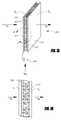
- thermoelectric devices todayThe most common configuration used in thermoelectric devices today is illustrated in FIG. 1A .
- P-type and N-type thermoelectric elements 102are arrayed in a rectangular assembly 100 between two substrates 104 .
- a current, Ipasses through both element types.
- the elementsare connected in series via copper shunts 106 saddled to the ends of the elements 102 .
- a DC voltage 108when applied, creates a temperature gradient across the TE elements.
- TEsare commonly used to cool liquids, gases and solid objects.
- Solid-state cooling, heating and power generation (SSCHP) systemshave been in use since the 1960's for military and aerospace instrumentation, temperature control and power generation applications. Commercial usage has been limited because such systems have been too costly for the function performed, and have low power density so SSCHP systems are larger, more costly, less efficient and heavier than has been commercially acceptable.
- Equation (3)The term on the right side of Equation (3) in brackets is independent of the size (or dimensions) of the TE system, and so the amount of cooling q OPT is only a function of material properties and K.
- Kcan be written as:
- K⁇ ⁇ ⁇ A C L C , ( 4 ) where ⁇ is the average thermal conductivity of the N & P materials; A C is the area of the elements; and L is the length of each element.
- thermoelectric systemsit is advantageous to make a device smaller for the same cooling output.
- An important limitation in thermoelectric systemsis that as, for example, the length L C is decreased for fixed A C , the ratio of the parasitic resistive losses to TE material losses, ⁇ C becomes relatively large:
- FIG. 1Cdepicts a typical TE couple. While several parasitic losses occur, one of the largest for a well-designed TE is that from shunt 106 .
- the resistance of shunt 106 per TE element 102is approximately,
- the resistance for a TE elementis:
- R OCP TE ⁇ L C B C ⁇ W C , ( 8 ) where L c is the TE element length.
- thermoelectric systemcomprises a first plurality of thermoelectric elements and a second plurality of thermoelectric elements.
- the thermoelectric systemfurther comprises a plurality of heat transfer devices.
- Each heat transfer devicehas a first side in thermal communication with two or more thermoelectric elements of the first plurality of thermoelectric elements and a second side in thermal communication with one or more thermoelectric elements of the second plurality of thermoelectric elements, so as to form a stack of thermoelectric elements and heat transfer devices.
- the two or more thermoelectric elements of the first plurality of thermoelectric elementsare in parallel electrical communication with one another, and the two or more thermoelectric elements of the first plurality of thermoelectric elements are in series electrical communication with the one or more thermoelectric elements of the second plurality of thermoelectric elements.
- thermoelectric systemcomprises a plurality of thermoelectric modules and a plurality of heat transfer devices.
- Each heat transfer devicecomprises a housing and one or more heat exchanger elements inside the housing.
- Each heat transfer deviceaccepts a working fluid to flow therethrough.
- At least some of the heat transfer devicesare in thermal communication with and sandwiched between at least two thermoelectric modules of the plurality of thermoelectric modules so as to form a stack of alternating thermoelectric modules and heat transfer devices arranged to provide thermal isolation along a direction of a working medium movement.
- thermoelectric systemcomprises a plurality of thermoelectric modules and a plurality of heat transfer devices. Each heat transfer device accepts a working fluid to flow therethrough. At least some of the heat transfer devices are in thermal communication with and sandwiched between at least two thermoelectric modules of the plurality of thermoelectric modules so as to form a stack of alternating thermoelectric modules and heat transfer devices arranged to provide thermal isolation along a direction of a working medium movement. A first working fluid is cooled by flowing through a first set of the heat transfer devices and a second working fluid is heated by flowing through a second set of the heat transfer devices.
- FIG. 1A-1Bdepicts a conventional TE module.
- FIG. 1Cdepicts a conventional TE couple.
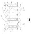
- FIG. 2depicts a general arrangement of a SSCHP system with thermal isolation and counter flow movement of its working media.
- FIG. 3depicts the temperature changes that occur in the media, as the working media progress through the system.
- FIGS. 4A-4Bdepict a system with three TE modules, four fin heat exchangers, and liquid-working media.
- FIGS. 5A-5Bdepict a system with two TE modules, a segmented heat exchanger to achieve a degree of thermal isolation with a single heat exchanger, and counter flow of the liquid media
- FIG. 6depicts and gaseous media system with two TE modules and ducted fans to control fluid flow.
- FIGS. 7A-7Ddepict a solid media system with counter flow to further enhance performance.
- the TE elementsutilize a high length to thickness ratio to achieve added thermal isolation.
- FIG. 8depicts a system with TE elements arranged so that current passes directly through the array and thereby lowers cost, weight and size while providing improved performance.
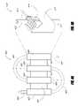
- FIG. 9depicts a system with TE elements, heat pipes and heat exchangers that is simple and low cost.
- the hot side and cold sideare separated by thermal transport through heat pipes.
- FIG. 10depicts a fluid system in which the fluid is pumped through the heat exchanger and TE module array so as to achieve a low temperature at one end to condense moisture out of a gas or a precipitate from a liquid or gas.
- the systemhas provisions to shunt working fluid flow to improve efficiency by lowering the temperature differential across portions of the array.
- FIG. 11depicts an array in which working fluid enters and exits at a variety of locations, and in which part of the system operates in counter flow and part in parallel flow modes.
- FIG. 12depicts a stack TE system with reduced parasitic electrical resistive losses.
- FIG. 13Adepicts details of a TE element and heat exchange member in a preferred embodiment for a stack system.
- FIG. 13Bdepicts a section of a stack system constructed from elements shown in FIG. 13A .
- FIG. 14depicts another TE element and heat exchanger configuration.
- FIG. 15depicts yet another TE element and heat exchanger configuration.
- FIG. 16depicts a stack configuration with two vertical rows of TE elements electrically in parallel.
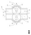
- FIG. 17depicts a cooling/heating assembly with two rows of TE elements electrically in parallel.
- FIG. 18depicts another configuration with two TE elements electrically in parallel.
- FIG. 19depicts a heat exchanger element with one portion electrically isolated from another portion.
- FIG. 20depicts another configuration of a heat exchanger element with one portion electrically isolated from another portion.
- FIG. 21depicts yet another configuration of a heat exchanger with one portion electrically isolated from another portion.
- FIG. 22depicts a heat exchanger segment configured in an array of electrically and thermally isolated portions.
- FIG. 23depicts a cooler/heater constructed in accordance with the concepts of FIG. 22 .
- FIG. 24Adepicts a heat exchange segment with TE elements aligned in the direction of fluid flow.
- FIG. 24Bdepicts segments of FIG. 24A configured as an isolated element heat exchanger array in which electrical current flows generally parallel to working medium flow.
- FIG. 25Adepicts segments of a design configured as an isolated element heat exchanger array in which electrical current flows generally perpendicular to the direction of current flow.
- FIG. 25Bdepicts a plan view of the assembly in FIG. 25A .
- FIG. 26Adepicts a TE heat exchanger module with reduced parasitic electrical resistance, which operates at relatively high voltage.
- FIG. 26Bdepicts a plan view of a heat exchanger array that uses TE modules of FIG. 26A .
- FIG. 27depicts an isolated element and stack configuration with heat transfer to moving solid members.
- FIG. 28depicts an isolated element stack array with heat transfer between a liquid and a gas.
- FIG. 29depicts a heat exchanger module with low parasitic electrical resistance for use in the stack array of FIG. 28 .
- FIG. 30depicts a segment of an isolated element heat exchanger with solid heat sink and moving gaseous working fluid.
- FIG. 31Adepicts a heat exchanger element with TE elements generally in the center to about double heat transfer from the element.
- FIG. 31Bdepicts another heat transfer element generally for liquids with the TE element generally in the center.
- FIG. 31Cdepicts yet another heat exchanger with the TE element generally in the center.
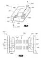
- FIG. 32schematically illustrates a partial cut-away view of an example heat transfer device in accordance with certain embodiments described herein.
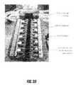
- FIG. 33is a view of an example thermoelectric system subassembly compatible with certain embodiments described herein.
- FIG. 34schematically illustrates the working fluid paths and the electrical connections of a heat exchanger subassembly or stack of an example thermoelectric system compatible with certain embodiments described herein.
- FIG. 35illustrates an example subassembly mounted in a test fixture.
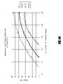
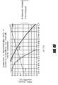
- FIG. 36shows a comparison of the measured performance results of the testing of the subassembly of FIG. 33 with simulated model results.
- FIG. 38shows a thermoelectric device with a plurality of subassemblies (front cover and insulation removed for illustration).
- FIG. 39shows a comparison of the measured experimental results for the device of FIG. 38 with computed model results.
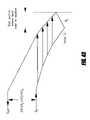
- FIG. 40schematically illustrates the temperature profiles of three thermoelectric systems as the working fluid circumnavigates the thermoelectric system.
- FIG. 42shows an example thermoelectric system used to validate the model under various conditions.
- FIG. 43shows the maximum ⁇ T C achievable for various numbers of thermal isolation stages.
- FIG. 44shows the effect of thermal isolation on maximum power.
- FIG. 45schematically illustrates a configuration utilizing the cross connection of fluids compatible with certain embodiments described herein.
- FIG. 46schematically illustrates the effect of introduction of moderate temperature fluid into the heated side where its temperature matches that of the original flow in accordance with certain embodiments described herein.
- FIG. 47shows an example temperature profile for an example thermoelectric system for removing vapor from a gas (e.g., dehumidification of air) in accordance with certain embodiments described herein.
- a gase.g., dehumidification of air
- FIG. 48shows the relative abilities of a conventional thermoelectric system and of a thermoelectric system utilizing thermal isolation to remove water from the air stream.
- FIG. 49shows a comparison of dehumidification ability of a scaled-up conventional thermoelectric system and a scaled-up thermally isolated thermoelectric system.
- thermoelectric module and TE moduleare used in the broad sense of their ordinary and accustomed meaning, which is (1) conventional thermoelectric modules, such as those produced by Hi Z Technologies, Inc. of San Diego, Calif., (2) quantum tunneling converters, (3) thermionic modules, (4) magneto caloric modules, (5) elements utilizing one, or any combination of thermoelectric, magneto caloric, quantum, tunneling and thermionic effects, (6) any combination, array, assembly and other structure of (1) through (6) above.
- thermoelectric elementis more specific to indicate an individual element that operates using thermoelectric, thermionic, quantum, tunneling, and any combination of these effects.
- thermoelectric or SSCHP systemsare described by way of example. Nevertheless, it is intended that such technology and descriptions encompass all SSCHP systems.
- thermoelectric element or array or modulemay be at ambient temperature with the “cold,” side at a cooler temperature than the ambient. The converse may also be true. Thus, the terms are relative to each other to indicate that one side of the thermoelectric is at a higher or lower temperature than the counter-designated temperature side.
- this disclosuredescribes a new family of SSCHP configurations. These configurations achieve compact, high-efficiency energy conversion and can be relatively low cost.
- TE elements or modulesare sandwiched between heat exchangers.
- the TE elementsare advantageously oriented such that for any two elements sandwiching a heat exchanger, the same temperature type side faces the heat exchanger.
- the cooler side of each of the TE elements sandwiching a heat exchangerface the same heat exchanger or shunt, and thus each other.
- at least one working mediumis passed sequentially through at least two heat exchangers so that the cooling or heating provided is additive on the working medium.
- a TE deviceachieves increased or improved efficiency by subdividing the overall assembly of TE elements into thermally isolated subassemblies or sections.
- the heat exchangersmay be subdivided so as to provide thermal isolation in the direction of working medium flow.
- a TE systemhas a plurality of TE elements forming a TE array with a cooling side and a heating side, wherein the plurality of TE elements are substantially isolated from each other in at least one direction across the array.
- the thermal isolationis in the direction of the working media flow.
- This thermal isolationcan be provided by having a heat exchanger configured in sections such that the heat exchanger has portions which are thermally isolated in the direction of working fluid flow.
- heat exchangers of the same temperature type for the working fluidprovides a type of thermal isolation in itself.
- the heat exchangers or the TE elements, or TE modules or any combinationmay be configured to provide thermal isolation in the direction of the working fluid flow over and above the thermal isolation provided by having a series or sequence of heat exchangers through which at least one working fluid passes in sequence.
- cooling and/or heating applicationsare equally applicable to power generation applications, and any configuration, design detail, and analogous part that may be combined in any way to produce an assembly for power generation, is also applicable.
- the systemmay be tuned in a manner to maximize the efficiency for the given application, but the general principles apply.
- thermoelectric systemhaving a plurality of N-type thermoelectric elements and a plurality of P-type thermoelectric elements.
- a plurality of first shunts and a plurality of second shuntsare provided. At least some of the first shunts are sandwiched between at least one N-type thermoelectric element and at least one P-type thermoelectric element, and at least some of the second shunts sandwiched between at least one P-type thermoelectric element and at least one N-type thermoelectric elements, so as to form a stack of thermoelectric elements, with alternating first and second shunts, wherein at least some of the first shunts and at least some of the second shunts project away from the stack in differing directions.
- thermoelectric elementsare constructed to be quite thin, such as from 5 microns, to 1.2 mm, from 20 microns to 200 microns for superlattice and heterostructure thermoelectric designs, and in another embodiment from 100 to 600 microns. These designs provide for significant reduction in the usage of thermoelectric material.
- thermoelectric systemfurther comprises a current source electrically coupled to the stack, the drive current traversing through the heat transfer devices and thermoelectric elements in series.
- the heat transfer devicesthermally isolate at least some of the P-type thermoelectric elements from at least some of the N-type thermoelectric elements.
- the heat transfer devicesaccept a working fluid to flow through them in a defined direction.
- the heat transfer devicesare heat exchangers and may have a housing with one or more heat exchanger elements inside.
- At least some of the first shuntsare constructed of a first electrode portion electrically isolated from and thermally coupled to a second shunt portion.
- FIG. 2illustrates a first generalized embodiment of an advantageous arrangement for a thermoelectric array 200 .
- the array 200has a plurality of TE modules 201 , 211 , 212 , 213 , 218 in good thermal communication with a plurality of first side heat exchangers 202 , 203 , 205 and a plurality of second side heat exchangers 206 , 207 209 .
- the designation first side heat exchanger and second side heat exchangerdoes not implicate or suggest that the heat exchangers are on one side or the other side of the entire SSCHP system, but merely that they are in thermal communication with either the colder side or the hotter side of the thermoelectric modules.
- thermoelectric modulesare actually sandwiched between thermoelectric modules. In that sense, they are in thermal communication with a first side or a second side of the thermoelectric modules.
- the colder side of a first TE module 201is in thermal contact with a first side heat exchanger 205 and the hot side of the TE module 201 is in thermal contact with an inlet second side heat exchanger 206 .
- a second working media 215such as a fluid, enters the array 200 in the upper right hand corner of FIG. 2 through the inlet second side heat exchange 206 , and exits near the lower left from a final or outlet second side heat exchanger 209 .
- a first working media 216enters at the upper left through an inlet first side heat exchanger 202 and exits near the lower right from a final or outlet first side heat exchanger 205 .
- Electrical wires 210(and similarly for other TE Modules) connected to a power supply, not shown, connect to each TE module 201 .
- First conduits 208represented as lines on FIG. 2 , convey the second working media 215 and second conduits 204 convey the first working media 216 sequentially through various heat exchangers 202 , 203 , 205 , 206 , 207 and 209 as depicted.
- the second working media 215absorbs heat from the TE module 201 as it passes downward through the inlet second side heat exchanger 206 .
- the second working media 215passes through conduit 208 and upwards into and through the second side heat exchanger 207 .
- In good thermal communication with the heat exchanger 207are the hotter sides of the TE modules 211 and 212 , which have been configured so that their respective hotter sides face toward one another to sandwich the second side heat exchanger 207 .
- the second side working media 215is further heated as it passes through the second side heat exchanger 207 .
- the second side working media 215next passes through the second side heat exchanger 209 , where again, the hotter sides of the TE modules 213 and 218 sandwich and transfer heat to the second side heat exchanger 209 , further heating the second side working media 215 . From the heat exchanger 209 , the second working media 215 exits the array 200 from the outlet or final second side heat exchange 209 .
- the first working media 216enters the inlet first side heat exchanger 202 at the upper left corner of FIG. 2 .
- This heat exchanger 202is in good thermal communication with the colder side of the TE module 218 .
- the first working media 216is cooled as it passes through the inlet first side heat exchanger 202 , on through another first side exchanger 203 and finally through the outlet first side heat exchanger 205 , where it exits as colder working media 217 .
- thermoelectric cooling and heatingis provided by electrical power through wiring 210 into TE module 218 , and similarly into all the other TE modules.
- working mediais placed in good thermal contact with the cold side of the TE module at the left hand side of the array, so that heat is extracted from the media.
- the mediathen contacts a second and third TE module where additional heat is extracted, further cooling the media.
- the process of incremental coolingcontinues, as the media progresses to the right through the desired number of stages.
- the mediaexits at the right, after being cooled the appropriate amount.
- a second mediaenters the system at the far right and is incrementally heated as it passes through the first stage. It then enters the next stage where it is further heated, and so on.
- the heat input at a stageis the resultant of the heat extracted from the adjacent TE modules' cold sides, and the electrical power into those modules.
- the hot side mediais progressively heated as it moves in a general right to left direction.
- the systemprovides benefit if both media enter at the same temperature and progressively get hotter and colder.
- the mediacan be removed from or added to the cool or hot side at any location within the array.
- the arrayscan be of any useful number of segments such as 5, 7, 35, 64 and larger numbers of segments.
- the systemcan also be operated by reversing the process with hot and cold media in contact with TE modules, and with the hot and cold media moving from opposite ends (as in FIG. 2 but with the hot media entering as media 216 and the cold media entering as media 215 ).
- the temperature gradient so induced across the TE modulesproduces an electric current and voltage, thus converting thermal power to electrical power. All of these modes of operation and those described in the text that follows are part of the inventions.
- the progressive heating and cooling of media in a counter flow configuration as described in FIG. 2can produce higher thermodynamic efficiency than under the same conditions in a single TE module without the benefit of the thermal isolation.
- the configuration shown in FIG. 2thus presents an SSCHP system 200 that obtains thermal isolation through the segments or stages of heat exchangers sandwiched between thermoelectric modules in a compact easily producible design.
- thermoelectric modulesthemselves may be constructed to provide thermal isolation in the direction of media flow and each heat exchanger or some of the heat exchangers may be configured to provide thermal isolation in a individual heat exchanger through a configuration as will be described further in FIG. 5 or other appropriate configurations.
- the heat exchangercould be segmented in the direction of flow to provide increased thermal isolation along the flow of a single TE module such as the TE module 218 and the inlet heat exchanger 202 .
- FIG. 3depicts an array 300 of the same general design as in FIG. 2 , consisting of a plurality of TE modules 301 and colder side heat exchangers 302 , 305 , and 307 connected so that a first working medium 315 follows the sequential heat exchanger to heat exchanger path shown.
- a plurality of hot side heat exchangers 309 , 311 and 313convey a hotter side working medium 317 in a sequential or staged manner in the direction shown by the arrows.
- the TE modules 301are arranged and electrically powered as in the description of FIG. 2 .
- the lower half of FIG. 3depicts the cold side temperatures or temperature changes 303 , 304 , 306 , 308 of the colder side working medium and hot side temperatures 310 , 312 , 314 of the hotter side working medium.
- the colder side working medium 315enters and passes through an inlet colder side heat exchanger 302 .
- the working medium's temperature drop 303 in passing through the inlet colder side heat exchanger 302is indicated by the drop 303 in the cold side temperature curve Tc.
- the colder side working medium 315is further cooled as it passes through the next stage colder side heat exchanger 305 , as indicated by a temperature drop 304 and again as it passes through a third colder side heat exchanger 307 , with an accompanying temperature drop 306 .
- the colder side working medium 315exits as colder fluids 316 at temperature 308 .
- the hotter side working medium 317enters a first or inlet hotter side heat exchanger 309 and exits at a first temperature 310 as indicated by the hotter side temperature curve T H in the FIG. 3 .
- the hotter side working mediumprogresses through the array 300 in stages as noted in FIG. 2 , getting progressively hotter, finally exiting after passing through outlet hotter side heat exchanger 313 as hotter working fluid at 318 and at a hotter temperature 314 .
- stagesthat is TE modules and heat exchangers
- efficiencyalso can increase with more stages, albeit at a diminishing rate.
- FIG. 4Adepicts an array 400 with three TE modules 402 , four heat exchangers 403 and two conduits 405 configured as described in FIGS. 2 and 3 .
- Colder and hotter side working fluidsenters at a colder side inlet 404 and a hotter side inlet 407 , respectively and exit respectively at a colder side exit 406 and a hotter side exit 408 .
- FIG. 4Bis a more detailed view of one embodiment of a heat exchanger 403 . It is shown as a type suitable for fluid media.
- the heat exchanger assembly 403has consists of an outer housing 412 with an inlet 410 and an exit 411 , heat exchanger fins 414 , and fluid distribution manifolds 413 .
- the operation of array 400is essentially the same as described in FIGS. 2 and 3 .
- the number of the TE modules 402is three in FIG. 4 , but could be any number.
- the housing 412is thermally conductive, being made from a suitable material such as corrosion protected copper or aluminum.
- heat exchanger fins 414advantageously are folded copper, or aluminum soldered or braised to the housing 412 , so as to achieve good thermal conductivity across the interface to the TE Module.
- the Fins 414can be of any form, but preferably of a design well suited to achieve the heat transfer properties desired for the system. Detailed design guidelines can be found in “Compact Heat Exchangers”, Third Edition by W. M. Kays and A. L. London.
- any other suitable heat exchangerscan be used, such as perforated fins, parallel plates, louvered fins, wire mesh and the like. Such configurations are known to the art, and can be used in any of the configurations in any of FIGS. 2 through 11 .
- FIG. 5Adepicts an alternative configuration to that of FIG. 4 for the conduit connections to provide flow from heat exchanger stage to heat exchanger.
- the array 500has first and second TE modules 501 and 510 , three heat exchangers 502 , 503 and 506 , and a conduit 504 .
- the particular number of two first side heat exchangers 502 , 503 and one second side heat exchanger 506is not restrictive and other numbers could be provided.
- FIG. 5Billustrates an enlarged view of a preferred embodiment for the heat exchangers 502 , 503 , 506 .
- This heat exchanger configuration as shown in FIG. 5Bwould be appropriate for the other embodiments and can be used in any of the configuration in FIGS. 2-8 and FIG. 11 .
- This advantageous embodiment for one or more of the heat exchangers in such configurationshas an outer housing 516 with segmented heat exchanger fins 511 separated by gaps 513 .
- Working fluidenters through an inlet 505 and exits through exit 508 .
- the heat exchangercould be made so that it is anisotropic such that it is thermally conductive for a section and non-thermally conductive for another section rather than having actual physical gaps between heat exchanger fins.
- thermal isolationto be obtained between stages of an individual heat exchanger segment and another individual heat exchanger segment in the direction of flow. This would be thermal isolation provided in addition to the thermal isolation provided by having stages of heat exchangers in the embodiments described in FIGS. 2-5 .
- a first working fluid 507which, for example is to be heated, enters an inlet 505 and passes downward through an inlet or first heat exchanger 502 in thermal communication with a first TE module 501 .
- the working fluid 507exits at the bottom and is conducted to subsequent heat exchanger 503 through conduit 504 , where it again passes in a downward direction past a second TE module 510 and exits through as a hotter working 508 .
- a second working fluid 517enters from the bottom of FIG. 5A through inlet 518 and travels upward through a third heat exchanger 506 past the colder sides (in the present example) of TE modules 501 and 510 .
- the heat exchanger 506is in good thermal communication with the colder sides of the TE modules 501 and 510 .
- the working fluids 507 and 517form a counter flow system in accordance with the teaching of U.S. Pat. No. 6,539,725 referenced above.
- the heat exchangers 502 , 503 and 506are constructed to have high thermal conductivity from the faces of the TE modules 501 , 510 , 510 , through the housing 516 and to the heat exchanger fins 511 (depicted in four isolated segments).
- FIG. 6depicts yet another heater/cooler system 600 that is designed to operate beneficially with working gases.
- the heater/cooler 600has TE modules 601 , 602 in good thermal communication with first side heat exchangers 603 , 605 and second side heat exchangers 604 .
- a first working fluid, such as air or other gases 606is contained by ducts 607 , 708 , 610 and a second working fluid 616 is contained by ducts 615 , 613 .
- Fans or pumps 609 , 614are mounted within ducts 608 , 615 .
- the first working fluid 606enters the system 600 through an inlet duct 607 .
- the working fluid 606passes through a first heat exchanger 603 where, for example, it is heated (or cooled).
- the working fluid 606then passes through the fan 609 which acts to pump the working fluid 606 through the duct 608 , and through the second heat exchanger 605 , where it is further heated (or cooled), and out an exit duct 610 .
- a working fluidsuch as air or another gas, enters through an inlet duct 615 . It is pushed by a second fan or pump 614 through a third heat exchanger 604 where, in this example, it is cooled (or heated).
- the cooled (or heated) working fluid 616exits through an exit duct 613 .
- the system 600can have multiple segments consisting of additional TE modules and heat exchangers and isolated, segmented heat exchangers as described in FIG. 5B . It can also have multiple fans or pumps to provide additional pumping force.
- one ductfor example 607 , 608 , can have one fluid and the other duct 613 , 615 a second type of gas. Alternately, one side may have a liquid working fluid and the other a gas. Thus, the system is not restricted to whether a working medium is a fluid or a liquid.
- the exit duct 613could be routed around the fan duct 609 .
- FIG. 7Adepicts a heating and cooling system 700 for beneficial use with a fluid.
- the assemblyhas a plurality of TE modules 701 with a plurality of first side working media 703 and a plurality of second side working media 704 .
- both the first side working media 703 and the second side working media 704form disks.
- the first side working media 703are attached to a first side shaft 709
- the second side working media 704are attached to a second side shaft 708 .
- the shafts 708 , 709are in turn attached to first side motor 706 and second side motor 705 , respectively, and to corresponding bearings 707 .
- the preferred direction of motor rotationis indicated by arrows 710 and 711 .
- a separator 717both divides the array into two portions and positions the TE modules 701 .
- the TE modules 701held in position by the separator 717 , are spaced so as to alternately sandwich a first side working medium 703 and a second side working medium 704 .
- the modulesare oriented such that their cold sides and hot sides face each other as in the previous embodiments.
- the working media 703 , 704are in good thermal communication with the TE elements 701 .
- Thermal grease or the likeis advantageously provided at the interface between the thermoelectric element 701 and the working media 703 , 704 . The purpose of the grease becomes apparent in the discussion below regarding the operation of the working media 703 , 704 .
- a first side housing section 714 and second side housing section 715contain fluid conditioned by the system 700 . Electrical wires 712 , 713 connect to the TE modules 701 to provide drive current for the TE modules.
- FIG. 7Bis a cross sectional view 7 B- 7 B through a portion of the system 700 of FIG. 7A .
- a first fluid 721 and a second fluid 723are represented along with their direction of flow by arrows 721 and 723 .
- the first fluidexits as represented by the arrow 722 and a second exits as represented by the arrow 724 .
- the system 700operates by passing current through electrical wires 712 and 713 to TE modules 701 .
- the TE modules 701have their cold and hot sides facing each other, arranged in the fashion as described in FIGS. 2 and 3 . For example, their adjacent cold sides both face the first side working media 703 and their hot sides face the second side working media 704 .
- the Separator 717serves the dual function of positioning the TE modules 701 and separating the hot side from the cooled side of the array 700 .
- a second fluid 723is to be cooled.
- the coolingoccurs by thermal exchange with second side media 704 .
- the second side media 704rotate, the portion of their surface in contact with the colder side of the TE modules 701 at any given time is cooled.
- the second media 704cool the second side fluid that then exits at exit 724 .
- the second fluidis confined within the array 700 by the housing section 715 and the separator 717 .
- first fluid 721is heated by the first side media 703 in thermal contact with the hotter side of the TE modules 701 .
- Rotation(indicated by arrow 711 ) moves the heated portion of first media 703 to where the first fluid 721 can pass through them and be heated via thermal contact.
- the first fluid 721is contained between the housing 714 and the separator 717 and exits at exit 722 .
- thermally conductive grease or liquid metal such as mercurycan be used to provide good thermal contact between the TE modules 701 and the media 703 , 704 at the region of contact.
- FIGS. 7A and 7Bmay also be advantageously used to cool or heat external components such as microprocessors, laser diodes and the like.
- the diskswould contact the part using the thermal grease or liquid metal or the like to transfer the heat to or from the part.
- FIG. 7Cdepicts a modified version of the system 700 in which the TE modules 701 are segmented to achieve thermal isolation.
- FIG. 7Cshows a detailed view of the portion of array 700 in which TE modules 701 and 702 transfer thermal power to heat moving media 704 and 703 (the rotating discs in this example).
- the moving media 704 and 703rotate about axes 733 and 734 , respectively.
- the working media 704 and 703rotate in opposite directions as indicated by arrows 710 and 711 .
- moving media 704 , 703rotate, heat transfer from different sections of TE modules 701 and 702 come into thermal contact with them and incrementally change the temperature of the moving media 704 , 703 .
- a first TE module 726heats moving medium 704 at a particular location.
- the material of the moving media 704 at that locationmoves into contact with a second TE module 725 as moving medium 704 rotates counter clockwise.
- the same portion of moving medium 704then moves on to additional TE module segments 701 .
- the opposite actionoccurs as moving medium 703 rotates counterclockwise and engages TE modules 701 and then subsequently TE modules 725 and 726 .
- moving media 704 , 703have good thermal conductivity in the radial and axial directions, and poor thermal conductivity in their angular direction, that is, the direction of motion. With this characteristic, the heat transfer from one TE module 725 to another TE module 726 by conductivity through the moving media 704 and 708 is minimized, thereby achieving effective thermal isolation.
- TE elements 701are very thin compared to their length in the direction of motion of moving media 704 , 703 , and have relatively poor thermal conductivity in that direction, they will exhibit effective thermal isolation over their length. They will conduct heat and thus respond thermally as if they were constructed of separate TE modules 701 .
- This characteristic in combination with low thermal conductivity in the direction of motion within the moving media 704 , 703can achieve effective thermal isolation and thereby provides performance enhancements.
- FIG. 7Ddepicts an alternative configuration for moving media 704 , 703 in which the media are constructed in the shape of wheels 729 and 732 with spokes 727 and 731 . In the spaces between spokes 727 and 731 and in good thermal contact with them, are heat exchanger material 728 and 730 .
- the system 700can operate in yet another mode that is depicted in FIG. 7D .
- working fluid(not shown) moves axially along the axes of the array 700 passing through moving media 704 , 703 sequentially from one medium 704 to the next moving medium 704 , and so on in an axial direction until it passes through the last medium 704 and exits.
- a separate working fluidpasses through individual moving medium 703 axially through array 700 .
- the ducts 714 and 715 and separator 717are shaped to form a continuous ring surrounding moving media 704 , 703 and separating medium 704 from medium 703 .
- the hot side working fluidpasses through heat exchanger 728 , moves through the array 700 in the opposite direction of the working fluid moving through heat exchanger 730 .
- the array 700acts as a counterflow heat exchanger, and a succession of sequential heat exchangers 728 and 730 incrementally heat and cool the respective working fluids that pass through them.
- the thermally active componentscan be TE modules 701 that can be constructed so as to have effective thermal isolation in the direction of motion of the moving media 704 , 703 .
- the TE modules 701 and 702can be segments as described in FIG.
- the thermal conductivity of the moving media 704 , 703is further advantageous for the thermal conductivity of the moving media 704 , 703 to be low in the direction of motion so as to thermally isolate portions of the outer discs 729 and 732 of the moving media 704 , 703 .
- the designcould be further contain radial slots (not shown) in the sections 729 and 732 that are subject to heat transfer from TE modules 701 and 702 to achieve thermal isolation in the direction of motion.
- FIG. 8depicts another embodiment of a thermoelectric system an 800 having a plurality of TE elements 801 (hatched) and 802 (unhatched) between first side heat exchangers 803 and second side heat exchangers 808 .
- a power supply 805provides current 804 and is connected to heat exchangers 808 via wires 806 , 807 .
- the system 800has conduits and pumps or fans (not shown) to move hot and cold side working media through the array 800 as described, for example, in FIGS. 2 , 3 , 4 , 5 , 6 and 7 .
- TE modules(having many TE elements) are replaced by TE elements 801 and 802 .
- hatched TE elements 801may be N-type TE elements and unhatched TE elements 802 may be P-type TE elements.
- heat exchangers 803 and 808it is advantageous to configure heat exchangers 803 and 808 so that they have very high electrical conductivity.
- the housing of the heat exchangers 803 , 808 and their internal fins or other types of heat exchanger memberscan be made of copper or other highly thermal and electrical conductive material.
- the heat exchangers 803 and 808can be in very good thermal communication with the TE elements 801 and 802 , but electrically isolated.
- electrical shuntscan be connected to the faces of TE elements 801 and 802 to electrically connect them in a fashion similar to that shown in FIG. 1 , but with the shunts looped past heat exchangers 803 and 808 .
- DC current 804 passing from N-type 801 to P-type TE elements 802will, for example, cool the first side heat exchanger 803 sandwiched between them, and current 804 passing from P-type TE elements 802 to N-type TE elements 801 will then heat the second side heat exchanger 808 sandwiched between them.
- the Array 800can exhibit minimal size and thermal losses since the shunts, substrates and multiple electric connector wires of standard TE modules can be eliminated or reduced. Further, TE elements 801 and 802 can be heterostructures that accommodate high currents if the components are designed to have high electrical conductivity and capacity. In such a configuration, the array 800 can produce high thermal power densities.
- FIG. 9depicts a thermoelectric system 900 of the same general type as described in FIG. 8 , with P-type TE elements 901 and N-type TE elements 902 between, and in good thermal contact with first side heat transfer members 903 and second side heat transfer members 905 .
- the heat transfer members 903 and 905have the form of thermally conductive rods or heat pipes. Attached to, and in good thermal communication with the heat transfer members 903 and 905 are heat exchanger fins 904 , 906 , or the like.
- a first conduit 907confines the flow of a first working medium 908 and 909 and a second conduit 914 confines the flow of a second working fluid 910 and 911 .
- Electrical connectors 912 and 913conduct current to the stack of alternating P-type and N-type TE elements 901 , 902 , as described in FIG. 8 .
- the first working media 908becomes progressively hotter as it is heated by conduction from heat transfer fins 904 , which in turn have been heated by conduction through the first heat transfer members 903 .
- the first conduit 907surrounds and confines a first working media 908 so it exits at a changed temperature as working fluid 909 .
- Portions of the first conduit 907thermally insulate the TE elements 901 and 902 and the second side heat transfer members 905 from the first (hot in this case) working media 908 and 909 .
- the second working media 910enters through the second conduit 914 , is cooled (in this example) as it passes through the second side heat exchangers 906 and exits as cooled fluid 911 .
- the TE elements 901 , 902provide cooling to the second side heat transfer members 905 and hence, to heat exchanger fins 906 .
- the second side conduit 914acts to confine the second (cooled in this example) working media 910 , and to insulate it from other parts of array 900 .
- TE modulesmay be substituted for the TE elements 901 , 902 .
- the heat exchangers 904 , 906can be of any design that is advantageous to the function of the system.
- FIGS. 8 and 9provide a relatively easily manufacturable system that also provides enhanced efficiency from thermal isolation. For example, in FIG.
- the heat exchangers 808 , 803which alternate between P-type and N-type thermal electric elements, will either be of the colder or hotter heat exchanger type, but will be reasonably thermally isolated from each other and cause the thermoelectric elements of the P and N type to be reasonably thermally isolated from one another.
- FIG. 10depicts another thermoelectric array system ( 1000 ) that provides thermal isolation.
- this configurationmay perform the function of a system that utilizes cooling and heating of the same medium to dehumidify, or remove precipitates, mist, condensable vapors, reaction products and the like and return the medium to somewhat above its original temperature.
- the system 1000consists of a stack of alternating P-type TE elements 1001 and N-type TE elements 1002 with interspersed cold side heat transfer elements 1003 and hot side heat transfer elements 1004 .
- heat exchanger fins 1005 , 1006are provided for both the colder side heat transfer elements 1003 and the hotter side heat transfer elements 1004 .
- a colder side conduit 1018 and a hotter side conduit 1019direct working fluid 1007 , 1008 and 1009 within the array 1000 .
- a fan 1010pulls the working fluid 1007 , 1008 and 1009 through the array 1000 .
- colder side insulation 1012thermally isolates the working fluid 1007 while travelling through the colder side from the TE element stack and hotter side insulation 1020 preferably isolates the working fluid while travelling through the hotter side from the TE element stack.
- a baffle 1010 or the likeseparates the colder and hotter sides.
- the baffle 1010has passages 1010 for working fluids 1021 to pass through.
- fluid passages 1017allow fluid 1016 to enter the hot side flow passage.
- a screen 1011 or other porous working fluid flow restrictorseparates the colder from the hotter side of array 1000 .
- Condensate, solid precipitate, liquids and the like 1013accumulate at the bottom of the array 1000 , and can pass through a valve 1014 and out a spout 1015 .
- some of the working fluid 1021can be passed from the colder to the hotter side through bypass passages 1020 .
- the flow restrictor 1011may also act as a filter to remove precipitates from liquid or gaseous working fluids 1008 , or mist or fog from gaseous working fluids 1008 .
- additional hotter side coolant 1016can enter array 1000 through side passages 1017 , also for the purpose of reducing the hotter side working fluid temperature or increasing array 1000 efficiency.
- This configurationcan produce very cold conditions at the flow restrictor 1011 , so that working fluid 1008 can have substantial amounts of precipitate, condensate or moisture removal capability.
- power to the fan 1010can be reversed and the system operated so as to heat the working fluid and return it to a cool state.
- Thiscan be advantageous for removing reaction products, precipitates, condensates, moisture and the like that is formed by the heating process.
- flow restrictor 1011 , and/or heat exchangers 1005 and 1006can have catalytic properties to enhance, modify, enable, prevent or otherwise affect processes that could occur in the system.
- one or more pumpscan replace fan/motor 1010 to achieve advantageous performance.
- FIG. 11depicts a thermoelectric array 1100 similar in design to that of FIGS. 2 and 3 , but in which working media has alternate paths through the system.
- the array 1100has TE modules 1101 interdispersed between heat exchangers 1102 .
- a plurality of inlet ports 1103 , 1105 and 1107conduct working media through the array 1100 .
- a plurality of exit ports 1104 , 1106 and 1108conduct working media from the array 1100 .
- working media to be cooledenters at a first inlet port 1103 and passes through several of the heat exchangers 1102 , thereby progressively cooling (in this example), and exits through a first exit port 1104 .
- a portion of the working media that removes heat from array 1100enters through a second inlet port 1105 , passes through heat exchangers 1102 , is progressively heated in the process, and exits through a second exit port 1106 .
- a second portion of working media to remove heatenters a third inlet port 1107 , is heated as it passes through some of the heat exchangers 1102 and exits through a third exit port 1108 .
- This designallows the cool side working media which passes from the first inlet port 1103 to the first exit port 1104 to be efficiently cooled, since the hot side working media enters at two locations in this example, and the resultant temperature differential across the TE modules 1101 can be on average lower than if working media entered at a single port. If the average temperature gradient is lower on average, then under most circumstances, the resultant system efficiency will be higher.
- the relative flow rates through the second and third inlet port 1105 and 1107can be adjusted to achieve desired performance or to respond to changing external conditions.
- thermoelectric 100The basic underlying connections for a conventional thermoelectric 100 are shown in additional detail in FIG. 1C .
- a P-type element 110 and an N-type element 112are of the type well known to the art.
- Shunts 106are attached to, and in good electrical connection with, P-type and N-type TE elements 110 and 112 .
- large numbers of such TE elements and shuntsare connected together to form a TE module, as shown in FIG. 1A .
- the length of TE elements 110 , 112 in the direction of current flowis L C 116 ; their breadth is B C 117 ; their width is W C 118 , and their distance apart is G C 120 .
- the thickness of shunts 106is T C 109 .
- the dimensions B C , W C , and L C , along with the TE material's figure of merit, Z, the current 122 and the operating temperaturesdetermine the amount of cooling, heating or electrical power produced, as is well known to the art (See Angrist, S .W. “Direct Energy Conversion” 3 rd Ed. 1977 Ch. 4, for example).
- a TE configuration 1200has a plurality of first side TE elements 1201 , 1202 of alternating conductivity types sandwiched in series between shunts 1203 and a plurality of second side shunts 1204 , so that a current 1209 passes perpendicular to the breadth B B and width W B of the shunts rather than generally parallel to the breadth as in FIG. 1C .
- the ratio, ⁇ B of R PB to R OBis:
- R PBP SB ⁇ T B B B ⁇ W B ( 11 )
- R OBP TE ⁇ L B B B ⁇ W B ⁇ ⁇ so , ( 12 ) ⁇ B ⁇ ( T B B B ) ⁇ ( P SB P TE ) ( 13 )
- thermoelectric modulesFor today's typical thermoelectric modules
- the volume of the new configurationcan be compared to that of FIG. 1C .
- the area ratiomust remain the same, so;
- thermoelectric materialA C L C (20)
- V BA B L B (21) and
- V B V C⁇ ( A B A C ) ⁇ ( L B L C ) ⁇ ⁇ 1 6.4 2 ⁇ 1 41 ( 22 ) ( 23 )
- the TE stack configuration 1200 of FIG. 12has P-type TE elements 1201 and N-type TE elements 1202 of length L B 1205 .
- the direction of current flowis indicated by the arrow 1209 .
- the TE elementshave a breadth B B and a width W B .
- PN shuntsBetween N-type 1202 and P-type 1201 elements, in the direction of current flow, are the first side shunts 1203 (“NP shunts”).
- the PN shunts 1204extend generally in the opposite direction from the stack 1200 than the NP shunts 1203 . Angles other than 180° are also advantageous.
- NP shunts 1203are cooled and PN shunts 1204 are heated.
- the parasitic electrical resistance losses for the configuration 1200are lower typically than for the conventional configuration 100 of FIG. 1 for the same TE element dimensions.
- the TE length L B 1205is reduced to equate the ratio of parasitic electrical losses in the two configurations, the TE length L B 1205 will be smaller, and the configuration of FIG. 12 advantageously can operate at higher power density than that of FIG. 1 .
- the configuration 1200 of FIG. 12also uses less thermoelectric material, and can be more compact than in the conventional design of FIG. 1 .
- the shunts 1203 , 1204can serve the dual function of transmitting thermal power away from the TE elements 1201 , 1202 and exchange thermal power with an external object or medium, such as a working fluid.
- FIG. 13AAn illustration of a preferred embodiment 1300 of a shunt combined to form a heat exchanger 1302 is depicted in FIG. 13A .
- at least one TE element 1301is electrically connected, such as with solder, to a raised electrode surface 1303 of a heat exchange shunt 1302 .
- the shunt 1302can be constructed primarily of a good thermal conductor, such as aluminum, and have integral clad overlay material 1304 , 1305 , made of a high-electrical conductivity material, such as copper, to facilitate TE element 1301 attachment and current flow at low resistance.
- FIG. 13Bdepicts a detailed side view of a portion of a stack thermoelectric assembly 1310 made up of the thermoelectric shunts 1302 and TE elements 1301 of FIG. 13A .
- a plurality of shunts 1302 with raised electrode surfaces 1303are electrically connected in series to TE elements 1301 of alternating conductivity types.
- the shunts 1302will be alternately heated and cooled when an appropriate current is applied.
- the thermal power producedis transported away from the TE elements 1301 by the shunts 1302 .
- the raised electrodes 1303facilitate reliable, low-cost, stable surfaces to which to attach the TE elements 1301 .
- a stack of a plurality of these assemblies 1310may be provided. An array of stacks could also be used which also further facilitates thermal isolation.
- the electrodes 1303advantageously can be shaped to prevent solder from shorting out the TE elements 1301 . Also, the electrodes 1303 advantageously can be shaped to control the contact area and hence, current density, through the TE elements 1301 .
- FIG. 14An example of a portion of a shunt heat exchanger 1400 is depicted in FIG. 14 .
- This portion 1400has increased surface area to aid heat transfer.
- a TE element 1401is attached to a shunt 1402 , preferably constructed as depicted in FIG. 13A , or as in other embodiments in this application.
- Heat exchangers 1403 , 1404such as fins, are attached with good thermal contact, such as by brazing, to the shunt 1402 .
- a working fluid 1405passes through the heat exchangers 1403 , 1404 .
- the shunt portion 1400is configured so that as the working fluid 1405 passes through the heat exchangers 1403 , 1404 , thermal power is transferred efficiently.
- the size of materials and proportions of the shunt 1402 and heat exchangers 1403 , 1404are designed to optimize operating efficiency when combined into a stack such as described in FIGS. 12 and 13B .
- the heat exchangers 1403 , 1404can be louvered, porous or be replaced by any other heat exchanger design that accomplishes the stated purposes such as those described in “Compact Heat Exchangers”, Third Edition, by W. M. Kays and A. L. London.
- the heat exchangers 1403 , 1404can be attached to the shunt 1402 by epoxy, solder, braze, weld or any other attachment method that provides good thermal contact.
- FIG. 15Another example of a shunt segment 1500 is depicted in FIG. 15 .
- the shunt segment 1500is constructed of multiple shunt elements 1501 , 1502 , 1503 and 1504 .
- the shunt elements 1501 , 1502 , 1503 and 1504may be folded over, brazed, riveted to each other or connected in any other way that provides a low electrical resistance path for a current 1507 to pass and to provide low thermal resistance from a TE element 1506 to the shunts 1501 , 1502 , 1503 and 1504 .
- the TE element 1506is advantageously attached to segment 1500 at or near a base portion 1505 .
- the shunt segment 1500depicts a design alternative to the shunt segment 1400 of FIG. 14 , and can be configured in stacks as depicted in FIGS. 12 and 13 , and then in arrays of stacks if desired. Both the configurations in FIGS. 14 and 15 can be automatically assembled to lower the labor cost of the TE systems made from these designs.
- Shunt segmentscan also be formed into stack assemblies 1600 as depicted in FIG. 16 .
- Center shunts 1602have first side TE elements 1601 of the same conductivity type at each end on a first side and second side TE elements 1605 of the opposite conductivity type at each end of the opposite side of the center shunts 1602 .
- Between each center shunt 1602 to form a stack of shunts 1602is placed a right shunt 1603 and a left shunt 1604 , as depicted in FIG. 16 .
- the right shunts 1603are placed such that the left end is sandwiched between, the TE elements 1601 , 1605 in good thermal and electrical contact.
- the left side shunts 1604are positioned such that the right end is sandwiched between TE elements 1601 , 1605 , and are in good thermal and electrical contact.
- the shunts 1602 , 1603 and 1604are alternately stacked and electrically connected to form a shunt stack 1600 .
- a first working fluid 1607 and a second working fluid 1608pass through the assembly 1600 .
- the stackmay be, and likely will, consist of many additional shunt elements in the stack.
- the small portions of a stack assembly 1600are merely depicted to provide the reader with an understanding. Further replication of such stacks is clear from the figures.
- additional stacksthermally isolated in a direction of working fluid flow could be provided.
- the stack assembly 1600forms a solid-state heat pump for conditioning fluids. It is important to note that the stack 1600 can have few or many segments and can thereby operate at different power levels, depending on the amount of current and voltage applied, component dimensions and the number of segments incorporated into the assembly. Arrays of such stacks may also be advantageous. In a situation where arrays of such stacks 1600 are used, it would be preferable to provide thermal isolation in the direction of fluid flow as described in U.S. Pat. No. 6,539,725 for improved efficiency.
- shunts 1602 , 1603 , 1604can be replaced by other shapes such as, but not limited to, those depicted in FIGS. 14 and 15 , to improve performance.
- FIG. 17A variation to the stack assembly 1600 depicted in FIG. 16 is illustrated in FIG. 17 .
- a TE assembly 1700is constructed of right side shunts 1703 and left side shunts 1704 to form a generally circular shape.
- the right side shunts 1703are advantageously configured to form a partial circle as are the left side shunts 1704 .
- the shunts which become cold during operationmay be either larger or smaller than the shunts that become hot, depending on the particular goals of the device.
- the substantially circular configurationis not necessary, and other configurations of the shunt segments shown in FIG. 17 to create a center flow portion could be used.
- the right side shuntscould be half rectangles or half squares
- the left side shunts 1704could be half rectangles or squares.
- one sidecould be multi-sided and one side could be arcuate.
- the particular shape of the shuntsare changeable.
- the TE elements 1701 and 1702of alternating conductivity type, as discussed for FIG. 16 , are electrically connected in series in the stack assembly 1700 .
- a fluid 1712passes into the central region formed by the shunts 1703 , 1704 .
- a first portion 1707 of the fluid 1712passes between the right side shunts 1703 and a second portion 1706 of the working fluid 1712 passes between the left side shunts 1704 .
- a power supply 1708is electrically connected to the TE elements by wires 1712 , 1713 that are connected to the stack at connections 1710 and 1711 .
- a fan 1709may be attached to one (or both) ends of the stack.
- a pump, blower, or the likecould be used as well.
- the fan 1709When power is applied to the fan 1709 , it pumps the working fluid 1712 through the assembly 1700 .
- the first fluid portion 1707 of working fluid 1712is cooled as it passes through them.
- the second portion 1706 of working fluidis heated as it passes through heated left side shunts 1704 .
- the assembly 1700forms a simple, compact cooler/heater with a capacity and overall size that can be adjusted by the number of shunts 1703 , 1704 utilized in its construction. It is apparent that the shunts 1703 , 1704 could be angular, oval or of any other advantageous shape. Further, the shunts can be of the designs depicted in FIGS. 14 , 15 or any other useful configuration.
- thermoelectric system of FIGS. 12 , 14 , 15 , 16 and 17more than one TE element can be used in one or more portions of an array as is depicted in FIG. 18 .
- TE elements 1801 , 1804are connected to raised electrode surfaces 1804 on each side of shunts 1802 , 1803 .
- a number of TE elements 1801electrically in parallel, can increase mechanical stability, better distribute thermal power and add electrical redundancy to the system. More than two TE elements 1801 can be used in parallel.
- FIGS. 12-13it is desirable to have exposed portions of shunts in accordance with FIGS. 12-13 electrically isolated from an electrode portion.
- FIG. 19One example of such a shunt is depicted in FIG. 19 .
- an electrical insulation 1905isolates an electrode portion 1903 of a shunt 1900 from a heat exchange portion 1904 of the shunt 1900 .
- TE elements 1901 , 1902are preferably mounted on the electrode portion 1903 .
- the electrical insulation 1905is a very good thermal conductor such as alumina, thermally conductive epoxy or the like.
- the interface shape formed by electrical insulation 1905is a shallow “V” shape to minimize thermal resistance. Any other shape and material combination that has suitably low interfacial thermal resistance can be used as well.
- a stack of such shunts 1900can be used as described previously.
- FIG. 20An alternate form of electrical isolation is shown in another shunt segment 2000 assembly depicted in top view in FIG. 20 .
- First TE elements 2001are connected to a left shunt 2003 of shunt segment array 2000
- second TE elements 2002are connected to a right shunt 2004 of shunt segment array 2000 .
- Electrical insulation 2005is positioned between left side shunt segments 2003 and right side shunt segments 2004 .
- the configuration depicted in FIG. 20provides electrical isolation between TE elements 2001 and 2002 while retaining mechanical integrity of the overall shunt 2000 .
- the electrical insulation 2005need not provide particularly good thermal conductivity since the sources of thermal power, the TE elements 2001 and 2002 , can cool or heat the left and right shunt segments 2003 , 2004 , at different levels, provided electrical insulation 2005 is on average centered between the TE elements 2001 and 2002 .
- two TE elements 2001 and two second TE elements 2002are depicted, a larger TE element or a larger number of TE elements on each side could be utilized.
- Two first TE elements 2001 and two second TE elements 2002are merely selected for illustration of a good stable mechanical structure.
- the first TE element 2001 and the second TE elements 2002need not be, but may be, of differing conductivity types.
- FIG. 21An alternate method of achieving electrical isolation within a shunt 2100 is depicted in FIG. 21 .
- a shunt portion 2103 with two first TE elements 2101is mechanically attached to a second shunt portion 2104 with two second TE elements 2102 .
- Electrical insulation 2106mechanically attaches shunt portions 2103 and 2104 , which are also separated from one another by a gap 2105 .
- the electrical insulation 2106need not be a good thermal conductor.
- the TE elements 2101 and 2102each provide thermal power to the respective shunt portions 2103 and 2104 .
- Electrical insulation 2106can be adhesive-backed Kapton tape, injection molded plastic, hot melt adhesive or any other suitable material. As shown in plan view in FIG. 21 , the shunt portions 2103 2104 do not overlap to form a lap joint. Such a joint, with epoxy or other electrically insulating bonding agent could also be used.
- Another shunt segment array 2200has electrically isolated shunt segments in a rectangular TE array 2200 .
- First TE elements 2201are thermally connected to first shunt portions 2202
- second TE elements 2203are thermally connected to second shunt portions 2204 .
- Each shunt portionis separated electrically from the other shunt portions by gaps 2210 , 2211 .
- Electrical insulation 2208 at the left side of the assembly, insulation 2207 in the middle and insulation 2209 on the right sideare preferably provided.
- An arrow 2212indicates working fluid flow direction. This configuration can be operated at higher voltage and lower current than a similar array without electrical isolation.
- first TE elements 2201 and second TE elements 2203need not, but may be, of differing conductivity types. This will depend on the direction of desired current flow.
- the TE elements 2202 , 2203may, however, be at different potentials.
- the gaps 2210serve to effectively thermally isolate first shunt portions 2202 from each other, and second shunt portions 2204 from each other.
- the side insulation 2208 , 2209provide both thermal and electrical isolation while mechanically attaching the shunts together.
- Center insulation 2207provides electrical insulation and thermal isolation along its length.
- array 2200is constructed to produce thermal isolation in the direction of arrow 2212 as described in U.S. Pat. No. 6,539,725. This configuration can be operated at higher voltage and lower current than a similar array without electrical isolation.
- FIG. 23A cooling system 2300 that employs shunt segment arrays generally of the type described in FIG. 22 , is depicted in FIG. 23 .
- the cooling system 2300has inner shunt segments 2301 , 2302 connected mechanically by electrically insulating material 2320 such as tape.
- the inner shunt segments 2302are mechanically connected by electrically and thermally insulating material 2321 .
- the inner segments 2301are mechanically connected by electrically and thermally insulating material 2307 .
- the inner shunt segments 2301 , 2302separately are connected to TE elements at the ends (not shown) in a manner described for FIG. 22 .
- the TEsare sandwiched in the stack between inner shunt segments 2301 , 2302 and respective outer shunt segments 2303 , 2305 .
- the center shunt segments 2301separately are connected to outer left shunt segments 2305
- the inner shunt segments 2302are connected to right outer shunt segments 2303 .
- the right outer shunt segments 2303are similarly mechanically connected by electrically and thermally insulating material 2322 which is similar to electrically insulating material 2321 connecting the inner shunt segments 2302 .
- the left outer shunt segments 2305are similarly mechanically connected.
- a housing 2311holds a stack array of shunt segments and TEs.
- Terminal posts 2312 and 2314are electrically connected to inner segments 2301 .
- terminals 2315 and 2316connect to inner shunt segments 2302 .
- thermally and electrically insulating spacers 2309 , 2310are positioned between each inner and outer segment.
- a first working fluid 2317passes through the inner region and a second working fluid 2318 , 2319 passes through the outer regions.
- the inner shunt segments 2301 , 2302are cooled.
- the outer shunt segments 2303 , 2305are heated.
- the working fluid 2317 passing through the inner regionis cooled, and the working fluid 2318 , 2319 passing through the outer shunt segments 2303 , 2305 is heated.
- the housing 2311 and the insulators 2309 , 2310contain and separate the cooled fluid 2317 from the heated fluid 2318 , 2319 .
- each stack in the system 2300can be in series to operate at high voltage, in series/parallel to operate at about half the voltage or in parallel to operate at about 1 ⁇ 4 the voltage.
- Polaritycould be reversed to heat the inner working fluid 2317 and cool the outer working fluids 2318 , 2319 .
- More segmentscould be utilized in the direction of working fluids 2317 , 2318 , 2319 flow to operate at even higher voltage and to achieve higher efficiency from the resultant more effective thermal isolation.
- FIGS. 24A and 24BAnother compact design that achieves enhanced performance from thermal isolation uses combined shunt and heat transfer segments 2400 as depicted in FIGS. 24A and 24B .
- This designis very similar to that of FIG. 14 , but with TE elements 2401 , 2402 aligned in the general direction of fluid flow.
- the TE elements 2401 , 2402 of opposite conductivity typeare connected to an extension 2403 of a shunt 2404 .
- heat exchangers 2405 , 2406such as fins, are in good thermal contact with the shunt 2404 .
- a working fluid 2409is heated or cooled as it passes through heat exchanger fins 2405 , and 2406 , depending on the direction of current flow.
- FIG. 24Bdepicts a portion of a stack 2410 consisting of TE shunt segments 2400 as shown in FIG. 24A .
- Current 2417flows in the direction indicated by the arrow.
- a plurality of first side shunts 2400 and a plurality of second side shunts 2400 aare connected to TE elements 2411 .
- a first working fluid 2418flows along the lower portion of stack 2410 through the heat exchangers on the second side shunts 2400 a in FIG. 24 a , and a working fluid 2419 flows advantageously in the opposite direction through the heat exchangers of first side shunts 2400 .
- the upper portion of the stack 2410progressively cools fluid 2419 as it passes from one segment to the next, and the lower portion progressively heats fluid 2418 as it passes from one shunt 2400 a to the next.
- FIG. 25AAn alternative TE stack configuration 2500 is depicted in FIG. 25A .
- This TE stackachieves the benefits of thermal isolation with a working fluid 2513 flowing generally perpendicular to the direction of current flow 2512 .
- a first shunt 2502is connected electrically to a first TE element 2501 and is in good thermal contact with heat exchangers 2503 , 2504 .
- a second first side shunt 2506is similarly in good thermal contact with its heat exchangers 2508
- a third first side shunt 2505is in good thermal contact with its heat exchangers 2507 .
- first side shunt 2502 , 2506 and 2505Interspersed between each first side shunt 2502 , 2506 and 2505 are TE elements 2501 of alternating type and second side shunts 2509 , 2510 and 2511 projecting generally in the opposite direction, as with FIG. 12 .
- Second side shunts 2509 , 2510 and 2511are generally of the same shape and bear the same spatial relationship as first side shunts 2502 , 2506 and 2505 .
- a working fluid 2513passes through the stack assembly in the direction indicated by the arrow. When suitable current is applied vertically through the TE elements, first side shunts 2502 , 2505 and 2506 are heated and second side shunts 2509 , 2510 and 2511 are cooled.
- a full stack assemblyhas repeated sections of the array 2500 , in the direction of current flow, assembled so that the top of heat exchanger 2503 would be spaced closely to the bottom of the next sequential heat exchanger 2504 of another array portion.
- the thermal isolation in the direction of working fluid 2513 flowis readily apparent.
- FIG. 25Bis a plan view of the array portion 2500 depicted in FIG. 25A .
- the cooling of a plurality of TE elements 2501are interspersed with the plurality of first side shunts 2502 , 2506 , 2505 , and a plurality of second side shunts 2511 , 2509 and 2510 , so that the first side shunts 2502 , 2506 and 2505 alternate with the second side shunts 2511 , 2509 and 2510 .
- the shuntsare separated by gaps 2534 and are in good thermal contact with heat exchangers for each shunt.
- a first working fluid 2531passes along the upper section from right to left and a working fluid 2532 passes advantageously from left to right along the lower section.
- Thermal and electrical insulation 2533is preferably provided between each pair of shunts, except where the electrical current flows through the TEs and shunts.
- the working fluid 2531is progressively heated and the working fluid 2532 is progressively cooled.
- the insulation 2533prevents unnecessary thermal losses and also prevents the working fluids 2531 , 2532 from mixing.
- the array 2500operates in counter flow mode, and employs thermal isolation to enhance performance.
- the same array 2500can operate with the working fluids 2531 , 2532 moving in the same direction in parallel flow mode, and still have the benefits of thermal isolation to enhance performance.
- the TE elements 2521are not all of the same resistance, but have resistances that vary depending on the temperature and power differentials between individual TE elements, as described in U.S. Pat. No. 6,539,735.
- FIG. 26AAnother TE module 2600 is depicted in FIG. 26A , that uses the principles discussed in the present description to achieve operation at higher voltages and possible other benefits such as higher power density, compact size, ruggedness, higher efficiency.
- a first TE element 2601is sandwiched between a first end shunt 2603 and a second shunt 2604 .
- a second TE element 2602of opposite conductivity type is sandwiched between the second shunt 2604 and a third shunt 2605 . This pattern is continued to final end shunt 2606 .
- a current 2607flows into final end shunt 2606 , through the TE modules and out the first end shunt 2603 , as indicated by arrows 2608 and 2609 .
- Gaps 2611prevent electrical conduction and reduce thermal conduction between adjacent shunts.
- the first end shunt 2603 and the final end shunt 2606have an electrode surface 2612 .
- the other shuntshave shunt surfaces 2614 that are thermally conductive but electrically insulating from the body of the shunts.
- suitable current 2608passes through the TE module 2600 heating the upper surface and cooling the lower surface (or vice versa).
- the TE module 2600 depicted in FIG. 26Aconsists of five TE elements and six shunts.
- any odd number of TE elementscan be employed, spaced alternately with shunts as depicted.
- more than one TE element(of the same type as explained for FIG. 18 ) may be connected in parallel between each pair of shunts.
- an even number of TEscan be used, such as to have electrical power confined to electrically isolated portions of one surface.
- FIG. 26BAn array 2620 of TE modules 2600 is depicted in FIG. 26B .
- FIG. 26Bdepicts two TE modules 2600 , of the type shown in FIG. 26A , stacked on top of each other with a center heat transfer member 2635 sandwiched between first side shunts 2604 .
- Outer heat transfer members 2632 and 2636are thermally coupled to second side shunts 2605 .
- the shunt and heat transfer memberscan also be of any other suitable types, for example, the types presented in FIGS. 14 and 15 .
- a first end shunt 2603 of a first TE moduleis electrically connected to the outer heat transfer members 2632 .
- the other end shunt 2606 of the first or upper TE moduleis electrically connected to the center heat transfer member 2635 .
- a second end shunt 2606 a of the second TE moduleis electrically coupled to the center heat transfer member 2635 and the first end shunt 2603 a of the second TE module is electrically coupled to the outer heat transfer member 2636 on the bottom of FIG. 26B .
- the other shunts 2604 , 2605have electrical insulation 2612 that is thermally conductive.
- the shuntshave gaps 2611 to electrically isolate them from one another. Current flow is indicated by the arrows 2628 , 2629 , 2630 , 2631 and 2637 .
- the TE elements 2601 , 2602alternate in conductivity type.
- second side shunts 2605 and the outer heat transfer members 2632 and 2636are heated.
- the first side shunts 2604 and center heat transfer member 2635are cooled.
- the oppositeis true for reversed current.
- the operating currentcan be adjusted along with the corresponding voltage by adjusting the dimensions and number of TE elements 2601 , 2602 .
- power densitycan be adjusted.
- a larger number of shunts and TE elementscould be used, which would widen the configuration shown in FIG. 26B .
- further TE modules 2600could be stacked in a vertical direction.
- an array of such stacks into or out of the plane of FIG. 26Bcould be provided or any combination of the above could be utilized.
- thermal isolation principles in the direction of heat transfer or working fluid flowcould be utilized in accordance with the description in U.S. Pat. No. 6,539,725.
- FIG. 27An alternative embodiment of a TE module 2700 , similar in type to the TE module 2600 of FIG. 26A , is illustrated in FIG. 27 .
- End shunts 2705 , 2704are electrically connected to a power source 2720 and ground 2709 .
- TE elements 2701 , 2702are electrically connected to between the series of shunts 2703 , 2704 , 2705 , 2706 .
- all shunts 2703 , 2704 , 2705 , 2706are electrically isolated by insulation 2711 from first and second heat transfer members 2707 , 2708 .
- the shuntsare in good thermal contact with the heat transfer members 2707 , 2708 .
- First side heat transfer member 2708moves in the direction indicated by an arrow 2712 .
- the second side heat transfer member 2707moves in the opposite direction, as indicated by an arrow 2710 .
- the second side heat transfer member 2707When suitable current is applied to the TE module 2700 , the second side heat transfer member 2707 is cooled and the first side heat transfer member 2708 is heated. Operation is similar to that associated with the description of FIGS. 7A , 7 B, 7 C, and 7 D. It should be noted that the first and second heat transfer members 2707 , 2708 , need not be rectangular in shape as might be inferred from FIG. 27 , but may be disk shaped or any other advantageous shape, such as those discussed in FIG. 7A . With effective design, the TE module 2700 can also achieve the performance benefits associated with thermal isolation as discussed in U.S. Pat. No. 6,539,725.
- heat transfer components 2707 and 2708do not move.
- the TE module 2700is similar to a standard module as depicted in FIG. 1 , but can operate with a high power density and utilize relative thin TE elements 2701 , 2702 .
- the TE module 2700induces low shear stresses on the TE elements 2701 , 2702 that are produced by thermal expansion differences between the first side and second side shunts, for example. Because shear is generated in the TE module 2700 by the temperature differential across TE elements 2701 , 2702 , and is proportional to the width dimension, it can be much less than the shear in a standard TE module, in which the shear is proportional to the overall module width.
- FIG. 12The differences can be seen from a comparison of FIG. 12 with a standard module depicted in FIG. 1 .
- Standard modules with more than two TE elements of the same dimensions as those in the configuration of FIG. 12will exhibit disadvantageously high shear stresses. Such stresses limit thermal cycling durability and module size.
- FIG. 27also provides a good illustration to describe how the embodiments described in this specification can be used for power generation as well.
- the terminals 2709 , 2720are connected to a load rather than a power source in order to provide power to a load.
- the heat transfer members 2708 , 2707provide thermal power in the form of a temperature gradient.
- the temperature gradient between the first heat transfer member 2708 and second heat transfer member 2707causes the thermoelectric system 2700 to generate a current at terminals 2709 , 2720 , which in turn would connect to a load or a power storage system.
- the system 2700could operate as a power generator.
- the other configurations depicted in this descriptioncould also be coupled in similar manners to provide a power generation system by applying a temperature gradient and deriving a current.
- a TE heat transfer system 2800is depicted in FIG. 28 that uses a gas working fluid 2810 , and a liquid working fluid 2806 .
- first side shunt heat exchangers 2803are of construction depicted in FIG. 24A and FIG. 24B .
- the shunt heat exchangers 2803transfer thermal power with the gaseous working media 2810 .
- second side shunts heat exchanger 2804 , 2805transfer thermal power with liquid working media 2806 .
- a plurality of TE elements 2801 of opposite conductivity typesare sandwiched between second side shunts 2804 , 2805 and the shunt heat exchanger 2803 .
- the second side shunt heat exchangers 2804 , 2805are similarly sandwiched between TE elements 2801 of alternating conductivity type.
- a current 2812 , 2813passes through the system 2800 as represented by the arrows 2812 , 2813 .
- tubes 2814 , 2815pass the liquid working media 2806 from one shunt heat exchanger 2804 , 2805 to the next one.
- Operation of the TE heat transfer system 2800is similar to that of the description of FIG. 24B , with one working fluid 2810 being gaseous and the other 2806 being liquid.
- the benefits of thermal isolation as described in U.S. Pat. No. 6,539,725are also achieved with the design depicted in system 2800 .
- FIG. 29depicts details of a shunt heat exchanger 2900 .
- the assemblyadvantageously has a container 2901 constructed of very good thermally conductive material, an electrode 2902 constructed of very good electrically conductive material, and heat transfer fins 2905 and 2906 in good thermal contact with the top and bottom surfaces of container 2901 .
- the container 2901 and the electrode 2902are constructed of a single material, and could be unitary in construction.
- an interface 2904 between the bottom surface of container 2901 and electrode 2902has very low electrical resistance. Fluid 2909 passes through the shunt heat exchanger 2900 .
- TE elementsare electrically connected to the top and bottom portions of the electrode 2902 .
- the container 2901 and the fins 2905 , 2906are heated or cooled.
- the working fluid 2909 passing through the shunt heat exchanger 2900is heated or cooled by the heat exchange 2900 .
- the shunt heat exchanger 2900is of sufficiently good electrical conductivity that it does not contribute significantly to parasitic losses. Such losses can be made smaller by minimizing the current path length through electrode 2902 , maximizing electrical conductivity throughout the current path, and increasing electrode 2902 cross sectional area.
- the container 2901 top and bottom surfaces, and fins 2905 and 2906provide sufficient electrical conductivity in the direction of current flow, that the solid electrode body 2902 can be reduced in cross sectional area or completely eliminated as shown in the embodiment in FIG. 4B .
- a heat sink and fluid system 3000is depicted in FIG. 30 .
- TE elements 3001 of alternating conductivity typesare interspersed between fluid heat exchanges 3004 , each having shunt portions 3003 , and shunts 3002 and 3005 .
- Current 3006 , 3007flows through the shunt portions 3003 , the shunts 3002 and 3005 and the TE elements 3001 .
- a working fluid 3009flows as indicated by the arrow.
- Heat sinks 3010 , 3011are in good thermal contact with and electrically insulated from the shunts 3002 , 3005 .
- electrical insulation 3008 , 3012that advantageously has good thermal conductance confines the current flow 3001 , 3007 to the circuit path indicated.
- thermal poweris transferred to the heat sinks 3010 , 3011 and from the working fluid 3009 .
- the shunt heat transfer members 3004are thermally isolated from one another so that performance gains from thermal isolation are achieved with this embodiment.
- FIG. 31AAn alternative shunt heat exchanger embodiment 3100 is depicted in FIG. 31A .
- a shunt portion 3101has electrodes 3102 for connection to TE elements (not shown) and heat transfer extensions 3108 in good thermal contact with heat exchangers 3103 , such as fins.
- a fluid 3107passes through the heat exchangers 3103 .
- the shunt heat exchanger 3100preferably has electrodes 3102 located generally centered between heat transfer extensions 3108 .
- thermal powercan flow into and out of the TE assemblies in two directions, and thus can increase heat transfer capacity by about a factor of two per TE element in comparison to the embodiment depicted in FIG. 24A .
- the shunt sidemay have increased heat transfer characteristics such as by incorporation heat pipes, convective heat flow, or by utilizing any other method of enhancing heat transfer.
- FIG. 31Bdepicts a heat transfer shunt assembly 3110 with a shunt 3111 , electrodes 3112 and influent fluid ports 3113 , 3114 , and effluent fluid ports 3115 , 3116 .
- the heat transfer shunt assembly 3110can have increased heat transfer capacity per TE element and more fluid transport capacity than the system depicted in FIG. 29 .
- FIG. 31Cdepicts a shunt assembly 3120 with shunt member 3121 , electrodes 3122 and heat exchange surfaces 3123 , 3124 .
- the shunt assembly 3120can have approximately two times the heat transfer capacity per TE assembly as the embodiment depicted in FIGS. 26A and 26B .
- stacks of shunt assemblies 3120would alternate at approximately right angles to one another and the surfaces 3123 , 3124 opposite one another would both be heated, for example, and the next pair of surfaces in the stack at about a right angle to the heated pair, would be cooled.
- the surfaces 3123 , 3214could be at other angles such as 120° and be interdispersed with shunts 2604 as depicted in FIG. 26 . Any combination of multisided shunts is part of the inventions.
- thermoelectric elements discussed hereinmay be as thin as 5 microns to 1.2 mm in one general embodiment.
- thermoelectric elementsmay be between 20 microns and 300 microns thick, more preferably from 20 microns to 200 microns, and even from 20 microns to 100 microns.
- the thickness of the thermoelectric elementsis between 100 microns and 600 microns. These thicknesses for the thermoelectric elements are substantially thinner than conventional thermoelectric systems.
- TE elementsdo not necessarily require the TE elements to be assembled into arrays or modules.
- TE elementsare advantageously attached directly to heat transfer members, thereby reducing system complexity and cost.
- the features described abovemay be combined in any advantageous way without departing from the invention.
- the TE elementsare shown in the various figures to appear to be of similar sizes, the TE elements could vary in size across the array or stack, the end type TE elements could be of different size and shape than the P-type TE elements, some TE elements could be hetero structures while others could be non-hetero structure in design.
- the systems described in these figuresdo operate in both cooling/heating and power generation modes.
- specific changescan be implemented to optimize performance for cooling, heating or power generation.
- large temperature differentials200 to 2000° F.
- small temperature differentials(10 to 60° F.) are characteristic of cooling and heating systems.
- Large temperature differentialsrequire different construction materials and possibly TE modules and elements of different design dimensions and materials. Nevertheless, the basic concept remains the same for the different modes of operation.
- the designs described in FIGS. 5 , 8 and 9are advantageous for power generation because they offer the potential to fabricate simple, rugged, low-cost designs. However, all of the above mentioned designs can have merit for specific power generation applications and cannot be excluded.
- Thermoelectric cooling, heating and temperature control deviceshave important features that make them of great interest for use in several growing market sectors. For example, increased cooling capacity requirements for electronic chasses use small cooling systems with form factors not easily achieved with two-phase compressor systems. Similarly, local cooling and heating systems, quiet room heat pumps, and other applications could benefit by conversion from two-phase compressor-based technology to quiet, vibration-free solid-state solutions.
- adapting the technologyhas been slow, in part due to three deficiencies of such solid-state systems:
- thermoelectric designsadvantageously optimize alternative thermodynamic cycles capable of approximately doubling efficiency in important applications.
- the improvements in efficiency of certain embodimentsare associated with working fluid movement, such as found in HVAC and temperature control systems. Results have been experimentally verified in air- and liquid-based devices.
- high power density thermoelectric designsreduce thermoelectric material usage to a practical minimum, subject to the limitations of present thermoelectric material fabrication and heat transfer technology. Material use reduction has been enabled in certain embodiments described herein by improved heat transfer technology and more accurate modeling software. Certain embodiments described herein employ these technological advances and achieve substantial material reduction.
- Certain embodiments described hereinhave been accurately and comprehensively modeled with simultaneous, multidimensional optimization algorithms that efficiently optimize complex designs.
- the modelsallow design input variables to be constrained to ranges suitable for ease of manufacture, and other purposes. Also, design output can be constrained by imposing limits on volume, pressure drop, flow rate and other parameters.
- thermoelectric-based solid-state cooling, heating and temperature control systemswith 80 watts and 3500 watts of thermal power output.
- Certain other embodiments described hereinprovide thermoelectric systems with other ranges of thermal power output.
- Certain embodiments described hereincomprise a liquid-based heating, cooling, and temperature control system. Certain embodiments described herein include one or more of the following specific technical design objectives:
- FIG. 32schematically illustrates a partial cut-away view of an example heat transfer device 3200 in accordance with certain embodiments described herein and FIG. 33 is a view of an example thermoelectric system subassembly 3300 compatible with certain embodiments described herein.
- the thermoelectric systemcomprises a plurality of thermoelectric modules (not visible in FIG. 33 ) and a plurality of heat transfer devices 3200 .
- Each heat transfer device 3200comprises a housing 3210 and one or more heat exchanger elements 3220 inside the housing 3210 .
- Each heat transfer device 3200accepts a working fluid to flow therethrough.
- At least some of the heat transfer devices 3200are in thermal communication with and sandwiched between at least two thermoelectric modules of the plurality of thermoelectric modules so as to form a stack of alternating thermoelectric modules and heat transfer devices 3200 .
- the stackis arranged to provide thermal isolation in the direction of a working medium movement.
- the subassembly 3300is compressively loaded to assure mechanical stability.
- the housing 3210comprises copper and the one or more heat exchanger elements 3220 comprises copper fins.
- the housing 3210 of certain embodimentscomprises a plurality of portions (e.g., two drawn copper shells) which are fitted together to form the housing 3210 .
- the housing 3210is unitary in construction, with bends, folds, and/or removed material to define a volume through which the working fluid can flow.
- the heat exchanger elements 3220comprise a plurality of copper fins.
- the heat exchanger elements 3220 of a heat transfer device 3200in certain embodiments are unitary in construction, with bends, folds, and/or removed material to form a portion across which the working fluid can flow to transfer heat between the heat exchanger elements 3220 and the working fluid.
- the heat exchanger elements 3220can comprise folded copper fins positioned within the copper shells of the housing 3210 .
- the heat exchanger elements 3220comprise two or more fin assemblies, as schematically illustrated by FIG. 32 .
- the housing 3210 and the one or more heat exchanger elements 3220are unitary in construction, with bends, folds, and/or removed material to form the heat transfer device 3200 .
- the housing 3210comprises a first surface 3212 and a second surface 3214 generally parallel to the first surface 3212 .
- first surface 3212is in thermal communication and in electrical communication with at least a first thermoelectric module of the plurality of thermoelectric modules.
- second surface 3214is in thermal communication and in electrical communication with at least a second thermoelectric module of the plurality of thermoelectric modules. This second thermoelectric module is also in thermal communication and in electrical communication with at least a second thermoelectric module.
- alternate N- and P-type thermoelectric elementsare soldered or brazed directly to the first surface 3212 and the second surface 3214 , respectively, of the heat transfer device 3200 .
- the alternate N- and P-type thermoelectric elementsare also soldered or brazed directly to the neighboring heat transfer devices 3200 of the thermoelectric system.
- each heat transfer device 3200comprises an inlet 3230 through which the working fluid enters the heat transfer device 3200 and an outlet 3240 through which the working fluid exits the heat transfer device 3200 .
- the working fluidin certain embodiments flows through the inlet 3230 in a direction generally perpendicular to the first surface 3212 and flows through the outlet 3240 in a direction generally perpendicular to the second surface 3214 .
- the outlet 3240 of a heat transfer device 3200is fluidically coupled (e.g., by a fluid duct or conduit 3250 ) to the inlet 3230 of another heat transfer device 3200 .
- the two heat transfer devices 3200 fluidically coupled to one another by the fluid conduit 3250are spaced apart by a thermoelectric module, another heat transfer device 3200 , and another thermoelectric module, such that the working fluids move in a counter-flow pattern, with each fluid passing through every second heat transfer device 3200 .
- FIG. 34schematically illustrates the working fluid paths and the electrical connections of a heat exchanger subassembly 3300 (e.g., the stack) of an example thermoelectric system compatible with certain embodiments described herein.
- the currentflows along the length of the heat exchanger subassembly (e.g., the stack) 3300 .
- the subassembly 3300achieves a degree of electrical redundancy by incorporating electrical circuits through parallel thermoelectric elements.
- the series parallel redundancy shown in FIG. 34can advantageously add to device ruggedness, stability, and reliability of the thermoelectric system.
- the thermoelectric system of certain embodimentscomprises a first plurality of thermoelectric elements 3410 , a second plurality of thermoelectric elements 3420 , and a plurality of heat transfer devices 3200 .
- Each heat transfer device 3200has a first side 3432 in thermal communication with two or more thermoelectric elements 3410 of the first plurality of thermoelectric elements 3410 and a second side 3434 in thermal communication with one or more thermoelectric elements 3420 of the second plurality of thermoelectric elements 3420 , so as to form a stack of thermoelectric elements and heat transfer devices.
- the two or more thermoelectric elements 3410 of the first plurality of thermoelectric elements 3410are in parallel electrical communication with one another.
- thermoelectric elements 3410 of the first plurality of thermoelectric elements 3410are in series electrical communication with the one or more thermoelectric elements 3420 of the second plurality of thermoelectric elements 3420 .
- the one or more thermoelectric elements 3420 of the second plurality of thermoelectric elements 3420comprises two or more thermoelectric elements 3420 that are in parallel electrical communication with one another.
- thermoelectric elements 3410 of the first plurality of thermoelectric elements 3410are P-type, and in certain such embodiments, the thermoelectric elements 3420 of the second plurality of thermoelectric elements 3420 are N-type.
- Each heat transfer device 3200in certain embodiments thermally isolates the two or more thermoelectric elements 3410 of the first plurality of thermoelectric elements 3410 from the two or more thermoelectric elements 3420 of the second plurality of thermoelectric elements 3420 .
- the stackis arranged to provide thermal isolation in the direction of a working medium movement.
- each heat transfer device 3200accepts a working fluid to flow therethrough in a general direction of the heat transfer device 3200 .
- the general directions of two or more heat transfer devices 3200 of the plurality of heat transfer devices 3200are substantially parallel to one another.
- the arrows of the heat transfer devices 3200 in FIG. 34show the general directions for fluid flow of the heat transfer devices 3200 .
- the general directions of at least two heat transfer devices 3200 of the plurality of heat transfer devices 3200are substantially opposite to one another.
- the outlet 3240 of a heat transfer device 3430is fluidically coupled to the inlet 3230 of another heat transfer device 3430 .
- a first working fluid 3440is cooled by flowing through a first set of the heat transfer devices 3200 and a second working fluid 3450 is heated by flowing through a second set of the heat transfer devices 3200 .
- the first working fluid 3440flows generally along the stack in a first direction and the second working fluid 3450 flows generally along the stack in a second direction.
- the first direction and the second directionare generally parallel to one another. In certain embodiments, the first direction and the second direction are generally opposite to one another. In the example configuration of FIG.
- the working fluidsmove in a counter-flow pattern, with each fluid passing through every second heat transfer device 3200 .
- the thermoelectric elements 3410 , 3420 of certain embodimentsare alternately P- and N-type in the direction of current flow, such that alternate heat transfer devices 3200 are heat sources and heat sinks.
- the cooled working fluid 3440is thereby progressively cooled as it passes through the heat transfer devices 3200
- the heated working fluid 3450is thereby progressively heated as it passes through the heat transfer devices 3200 .
- the working fluids 3440 , 3450can flow in opposite directions, as shown schematically in FIG. 34 .
- the working fluids 3440 , 3450can flow in the same direction and can achieve similar improvements in performance compared to operation with the standard thermodynamic cycle. Under certain conditions, such as very small temperature differentials, efficiency can be slightly greater than that achieved with opposing flow. In certain embodiments, this geometry satisfies the basic condition of thermal isolation without the addition of extra components, and in practice, can reduce the total number of components used to achieve the intended performance characteristics.
- the example breadboard subassembly 3300 shown in FIG. 33was constructed in accordance with the model outputs for the optimized design.
- the example subassembly 3300is 87 mm by 39 mm by 15 mm.
- Each thermoelectric section sandwiched between two heat transfer devices 3200has four thermoelectric elements, each 4 mm by 3 mm in cross-sectional area and a thickness of 0.6 mm in the direction of current flow.
- the four thermoelectric elementsare electrically in parallel with one another between adjacent heat transfer devices 3200 .
- waterwas used as the working fluid.
- the uniformity of heat transfer and heat capacity propertiesfacilitated repeatable measurement of flow rates and the inlet and outlet temperatures. Thermal heat exchange with the environment and other sources of experimental inaccuracies were addressed and minimized. Test results were analyzed for accuracy by computing performance using two independent computational methods for the power input to the device, Q in .
- Test methodologieswere developed so that the test values as measured by the two methods were within at least 5% of one another.
- the subassembly 3300was mounted in a test fixture as shown in FIG. 35 .
- the subassembly 3300was mounted between two electrodes maintained at the inlet water temperature. Interfacial electrical and thermal losses were minimized by using liquid metal (GaInSn) external electrical interfaces to simulate solder (PbSn) electrical connection of an example complete system.
- the subassembly 3300was placed in a foam insulation structure to reduce heat exchange with ambient.
- FIG. 36shows a comparison of the measured performance results of the testing of the subassembly 3300 with simulated model results. These results show good correlation over a broad range of operating parameters. Accuracy of the model results were within 4% for operating conditions at and to the right (higher currents) of the point of peak COP for all of the temperature differentials tested. Test points to the left of the peak COP have not been included in the accuracy analysis. Such operating conditions are not typically of interest since they represent operating conditions that use much bulkier and more costly devices than those operating at the same COP on the right side of the peak. In addition, the very large slopes associated with this operating regime introduce both test errors and operating instabilities.
- the parameter, epsilonis the ratio of current I to I max , the calculated current for maximum cooling power.
- I max440 amperes.
- the subassembly 3300was tested at input currents from 30 to 150 amperes. Heated side to cooled side outlet temperature differentials ranged from 15° C. to 55° C. Input electrical power to the subassembly 3300 varied from 4.89 to 87.49 watts.
- thermoelectric module constructionBased on the calculated results for standard TE module systems and the stack design, comparisons of sizes, weights, columns and power of the standard thermoelectric module construction and the example subassembly 3300 in accordance with certain embodiments described herein are presented in Table 1. As shown in Table 1, in addition to the COP (efficiency) improvements of about 91%, the subassembly 3300 exhibits substantial volume, weight, and cost reductions compared to standard thermoelectric module designs. Thermoelectric subassembly volume and weight are reduced about 15% and 70%, respectively; thermoelectric material usage, and hence, material cost, is about one-fourth, and specific power increased by about a factor of 3.3.
- thermoelectric elementswere changed to three elements per layer, each 12 mm by 3 mm in cross-sectional area and 0.6 mm thick, thereby increasing the area of each thermoelectric layer. This was done to meet the need for a particular application in which the temperature differential was lower, by advantageously using more thermoelectric area per stage. As shown by comparing the results of FIGS. 36 and 37 , the device was predicted to have slightly higher efficiency than the thermoelectric subassembly 3300 under the specific operating condition plotted.
- the devicewas constructed in a 9 ⁇ 3 array with 1.5 mm semi-rigid insulation between thermoelectric subassemblies, so that the core thermoelectric assembly was compact.
- Ancillary partswere spaced apart with gaps filled with insulation, so as to allow access for thermocouples and other monitoring devices.
- the ancillary partsincluded: fluid manifolds, electrical connections between subassemblies, and springs to uniformly compress the subassemblies. No attempt was made to minimize weight or volume of the ancillary parts.
- the device of FIG. 38has the following nominal design properties:
- FIG. 39shows a comparison of the measured experimental results with the computed model results. The experimental results are in good agreement with the predicted results, based on simulations using the design modeling tool.
- Tests of the completed device of FIG. 38show comparable accuracy to that of the example thermoelectric subassembly 3300 , but testing was limited to fewer operating conditions because of power supply and working fluid flow rate capabilities of the test equipment used. Over the range of conditions tested, results did validate the model's performance perditions. Further, since the performance of the completed device and thermoelectric subassembly each agreed with the same predicted results for the subassembly, system level losses were shown to be sufficiently small so as to not invalidate the predicted performance at the system level. Hence, results for the completed device follow the predicted performance for the thermoelectric subassembly.
- thermoelectric cooler compatible with certain embodiments described herein with liquid working fluidcan have a high COP.
- thermal power levelsbetween 50 and 3,500 watts, such systems are viable candidates for liquid-based cooling applications. Since multiple identical subassemblies were used to demonstrate operation at 3,500 watts, it can be expected that very similar results would be observed for devices of at least 5,000 watt thermal capacity. Further, similar performance and model accuracy is obtained for operation in heating mode.
- a class of cooling, heating and temperature control applicationscan be targets for the TE technology of certain embodiments described herein.
- At least a portion of a single working fluidis circulated on both the heated and cooled sides of a thermoelectric system utilizing thermal isolation in the direction of flow.
- the working fluidis cooled, and is re-heated to somewhat above its original temperature during the return pass on the heated side.
- the thermal conductivity of the substrate and the heat exchange members on which the thermoelectric circuitry is mountedtends to make the temperature rather uniform over the entire surface of the device.
- thermoelectric deviceminimizes the thermal conductivity in the direction of flow, then by cooling the heat transfer fluid as it flows over the first side, and then heating it again by flowing it in counter-flow on the other side, the temperature difference across any part of the thermoelectric device is advantageously made smaller, resulting in large improvements in COP, ⁇ T, or both.
- FIG. 4Aschematically illustrates an example thermoelectric system 400 compatible with certain embodiments described herein.
- the thermoelectric system 400comprises a plurality of thermoelectric modules 402 and a plurality of heat transfer devices 403 .
- Each heat transfer device 403accepts a working fluid to flow therethrough.
- At least some of the heat transfer devices 403are in thermal communication with and sandwiched between at least two thermoelectric modules 402 of the plurality of thermoelectric modules 402 so as to form a stack of alternating thermoelectric modules 402 and heat transfer devices 403 .
- the stackis arranged to provide thermal isolation along a direction of a working medium movement.
- FIG. 33shows an example subassembly 3300 compatible with certain embodiments described herein.
- FIG. 40schematically illustrates the temperature profiles of three thermoelectric systems as the working fluid circumnavigates the thermoelectric system.
- the second working fluidcomprises the first working fluid after having flowed through the first set of heat transfer devices.
- the first working fluidreceives an increase in temperature at the cold end from the load due to Q L .
- the first working fluidis then fed back into the heated side as the second working fluid and exits at a temperature raised from the inlet temperature due to the sum of the input power, IV, and the load power Q L .
- the temperature at which the first working fluid is fed back into the heated sidedepends upon the relative sizes of the heat load and the ability of the coldest stage of the device to pump heat.
- the three profiles in FIG. 40show a range of possibilities for (i) small or no heat load, (ii) moderate heat load, and (iii) large heat load.
- the first working fluidis introduced to the cooled side at an inlet temperature T IN and is progressively cooled as it flows through along the cooled side to an end section where a heat load is applied.
- the first working fluidis heated by the heat load and is introduced as the second working fluid to the heated side and is progressively heated further as it flows along the heated side to the outlet.
- the outlet temperature T OUT of the second working fluidis higher than the inlet temperature T IN of the first working fluid.
- thermoelectric devicesA computer model for liquid-to-liquid thermoelectric devices was used to compare the performance of a conventional thermoelectric device to a device utilizing thermal isolation and the same working fluid on both sides of the device in accordance with certain embodiments described herein.
- FIG. 42shows an example thermoelectric system 4200 used to validate the model under various conditions.
- the thermoelectric system 4200comprises an inlet 4210 in fluidic communication with the cooled side of the thermoelectric system 4200 , a heater 4220 attached to the cooled end 4230 to provide a heat load, an outlet 4240 in fluidic communication with the heated side of the thermoelectric system 4200 , and a pair of electrodes 4250 to apply a current to the thermoelectric elements of the thermoelectric system 4200 .
- Insulating foamis used to insulate the thermoelectric system 4200 from ambient.
- FIG. 43shows the effect of thermal isolation on maximum ⁇ T C by plotting the maximum ⁇ T C achievable for various numbers of thermal isolation stages.
- FIG. 44shows the effect of thermal isolation on maximum power.
- Nis used for the number of stages of thermal isolation present in the thermoelectric system.
- the second working fluidcomprises one or more portions of the first working fluid after having flowed through one or more portions of the first set of heat transfer devices.
- the one or more portions of the first working fluidcomprise a plurality of portions of the first working fluid after having flowed through a plurality of portions of the first set of heat transfer devices.
- FIG. 45schematically illustrates a configuration utilizing the cross connection of fluids compatible with certain embodiments described herein. Multiple portions of the first working fluid are diverted from the cooled side to the second working fluid on the heated side at several points along the thermally isolated stack. This configuration results in high flows at the inlet and outlet and low flows at the cold end. The smaller temperature difference across the high flow end is the factor improving performance.
- the second working fluidcomprises a portion of the first working fluid that does not flow through at least a portion of the first set of heat transfer devices.
- FIG. 46schematically illustrates the effect of introduction of moderate temperature fluid into the heated side where its temperature matches that of the original flow in accordance with certain embodiments described herein. This introduction of a moderate temperature first working fluid into the second working fluid effectively removes the restriction of equal flows.
- the benefit of the use of the cooled flow in certain embodimentsis to make use of the cool fluid to further enhance the performance above that of one with simply independent flows.
- the thermoelectric systemprovides increased cooling capacity at large temperature differential from ambient, in a way that is much more efficient than that achieved with the conventional cascade geometry.
- the waste heat from each colder devicemust be passed through all of the higher temperature supporting devices, thus placing additional heat removal burdens on them over and above the heat removal from the cold surface of the coldest one.
- the wast heatdoes not accumulate as it passes from one set of thermoelectric elements to the next. Since the use of the same fluid on both sides of the thermoelectric system removes the degree of freedom associated with differing flow rates, there is advantageously an external reason for applying this restriction. In certain embodiments, this reason can be due to the nature of the working fluid, the pumping means, the efficiency or cost of pumping, or the nature of the necessary containment of the fluid, as well as others.
- FIG. 47shows an example temperature profile for an example thermoelectric system for removing vapor from a gas (e.g., dehumidification of air) in accordance with certain embodiments described herein.
- FIG. 47illustrates an example in which a first working fluid comprises vapor at a temperature above a condensation point of the vapor.
- the first working fluidis cooled to a temperature below the condensation point by flowing through at least a portion of the first set of heat transfer devices (e.g., the cooled side of the thermoelectric system) such that at least a portion of the vapor condenses to a liquid.
- the second working fluidcomprises the first working fluid without the at least a portion of the vapor.
- the first working fluid of humid airis introduced to the inlet of the thermoelectric system at a temperature T IN .
- the humid airflows through the cooled side of the thermoelectric system, it is cooled to the condensation point or dew point of the water vapor to be removed.
- the condensation pointis reached, the humidity is then 100% and beginning there, the thermoelectric system not only advantageously cools the air, but also removes enough heat to condense at least a portion of the water vapor out from the air.
- the desired concentration of water vaporis achieved and the now dehumidified air (without a portion of the water vapor) is ducted to the heated side of the thermoelectric system to return to a higher temperature (e.g., warm up as less humid air).
- the exit air temperature T OUTis elevated above the inlet air temperature T IN , for example to provide the warmth needed for typical defogging and demisting applications.
- gases and vaporsare also compatible with certain embodiments described herein.
- thermoelectric systemwas simulated as both a conventional thermoelectric system and as one with thermal isolation.
- a particular scenariowas chosen as an example of the analysis, namely to determine the reduction in the relative humidity from 90% in 40° C. air. Current and flow rate were varied to optimize the power available to cool and condense the moisture.
- FIG. 48shows the relative abilities of a conventional thermoelectric system and of a thermoelectric system utilizing thermal isolation to remove water from the air stream.
Landscapes
- Engineering & Computer Science (AREA)
- Mechanical Engineering (AREA)
- General Engineering & Computer Science (AREA)
- Physics & Mathematics (AREA)
- Thermal Sciences (AREA)
- Chemical & Material Sciences (AREA)
- Combustion & Propulsion (AREA)
- Cooling Or The Like Of Semiconductors Or Solid State Devices (AREA)
Abstract
Description
qCOPT=IOPTαC−½I2OPTR−KΔT, (1)
where:
- qCOPTis the optimum cooling thermal power;
- IOPTis the optimum current;
- α is the Seebeck Coefficient;
- R is the system electrical resistance;
- K is the system thermal conductance;
- ΔT is the difference between the hot and cold side temperatures; and
- TCis the cold side temperature.
Further, from Goldsmid's:
where:
- Z is the material thermoelectric figure of merit;
- TAVEis the average of the hot and cold side temperatures; and
- M=√{square root over (ZTAVE+1)}.
Substitution Equation (2) into (1) yields:
where λ is the average thermal conductivity of the N & P materials; ACis the area of the elements; and L is the length of each element.
where ρTEis the intrinsic average resistivity of the TE elements; ROCis the TE material resistance; and RPCis parasitic resistances.
where GCis the gap between the TE elements; BCis the TE element and shunt breadth; WCis the TE element and shunt width; TCis the shunt thickness; and PSCis the shunt resistivity.
where Lcis the TE element length.
Thus, using Equations (7) and (8) in (6):
Where;
Where
- TBis the shunt thickness
- LBis the TE element length
- ρSBis the shunt resistivity
- BBis the TE element and shunt active breadth
- WBis the TE elements and shunt active width
φC=φB (14)
or using Equations (9 and 12) in B;
- BC≈1.6 mm.
- WC≈1.6 mm.
- GC≈1.6 mm.
- TC≈0.4 mm.
and assume; - TB≈2 mm.
- PSB≈PSC
then,
and since;
AC=6.4AB. (19)
VC=ACLC (20)
VB=ABLB (21)
and;
- TE devices are generally about ¼ as efficient as two-phase compressor-based cooling systems, resulting in 4 times the operating costs and larger heat rejection components;
- Projected initial costs are at least double the cost of competitive systems; and
- Simulation tools that are capable of optimizing TE system design for cost, efficiency, size and other important parameters have not been available.
- Operating efficiencies at least 50% greater than that with conventional thermoelectric technology;
- Thermoelectric material usage less than 25% of commercial thermoelectric modules with the same thermal output;
- Readily manufactured and have the prospect of being low cost, compact, and minimum weight;
- Incorporate electrical redundancy;
- Nominal thermal pumping capacity of 3,500 watts in cooling mode; and
- Scalable to larger and smaller sizes between 50 and 5,000 watt thermal capacity.
- Area, thickness, and number of the thermoelectric elements;
- Number of thermally isolated segments in the direction of flow;
- Shell thickness, length, width, and construction material of the heat transfer device;
- Fin thickness, length, width, spacing, and construction material of the heat transfer device;
- Number of parallel thermoelectric segments;
- Thickness and material properties of braze joints of the heat transfer device;
- Thickness and material properties of solder layers; and
- Electrical and thermal interfacial properties of the thermoelectric electrodes.
The first four parameters listed above (except construction materials) were simultaneously optimized to yield the design parameters described below. Constraints were placed on the material thicknesses and spacing parameters to assure manufacturability. Liquid flow rates and temperature changes were fixed, and hence, were constraints applied during the optimization procedure to optimize the coefficient of performance (COP). Outputs of the simulations included: operating current and voltage, liquid pressure drops, number of thermoelectric elements, volume of thermoelectric material, and device weight and volume (excluding: manifolds, electrical and mechanical interface components, external insulation, and mounting brackets).
| TABLE 1 | ||
| Standard | ||
| Parameter | Design | |
| 3300 | ||
| Thermal cooling power at ΔTc= 10° C.; | 65.10 | 65.10 |
| ΔTh= 5° C. (watts) | ||
| Thermoelectric material weight (grams) | 48.37 | 11.34 |
| Heat transfer device weight (grams) | 290.0 | 129.4 |
| Weight of other materials (shunts, substrates, | 146.9 | 6.1 |
| sealants, wiring) (grams) | ||
| Total subassembly weight (grams) | 485.3 | 146.8 |
| Volume (liters) | 0.0616 | 0.0521 |
| Power density (watts/liter) | 1057 | 1250 |
| Specific cooling power (watts/gram) | 0.134 | 0.443 |
| Peak efficiency (COP) | 2.25 | 4.20 |
- Current: 86 amperes;
- Voltage: 8.7 volts;
- Thermal cooling power: 3500 watts;
- Liquid flow rate: 0.16 liters/second;
- Thermoelectric material weight: 306 grams;
- Device volume: 1.59 liters; and
- Device dry weight: 4.33 kilograms.
The thermoelectric subassemblies (see, e.g.,FIG. 33 ) were connected in parallel for fluid flow and in series for current flow. Manifolds to direct the fluid flow also acted as top and bottom structural members. The manifolds also housed the electrical connections.
Claims (33)
Priority Applications (2)
| Application Number | Priority Date | Filing Date | Title |
|---|---|---|---|
| US11/829,832US7946120B2 (en) | 2001-02-09 | 2007-07-27 | High capacity thermoelectric temperature control system |
| US13/089,681US20110209740A1 (en) | 2002-08-23 | 2011-04-19 | High capacity thermoelectric temperature control systems |
Applications Claiming Priority (9)
| Application Number | Priority Date | Filing Date | Title |
|---|---|---|---|
| US26765701P | 2001-02-09 | 2001-02-09 | |
| US09/844,818US6539725B2 (en) | 2001-02-09 | 2001-04-27 | Efficiency thermoelectrics utilizing thermal isolation |
| US10/227,398US7231772B2 (en) | 2001-02-09 | 2002-08-23 | Compact, high-efficiency thermoelectric systems |
| US40300103A | 2003-03-31 | 2003-03-31 | |
| US10/642,773US6959555B2 (en) | 2001-02-09 | 2003-08-18 | High power density thermoelectric systems |
| US11/136,334US7587902B2 (en) | 2001-02-09 | 2005-05-24 | High power density thermoelectric systems |
| US83400506P | 2006-07-28 | 2006-07-28 | |
| US83400706P | 2006-07-28 | 2006-07-28 | |
| US11/829,832US7946120B2 (en) | 2001-02-09 | 2007-07-27 | High capacity thermoelectric temperature control system |
Related Parent Applications (1)
| Application Number | Title | Priority Date | Filing Date |
|---|---|---|---|
| US11/136,334Continuation-In-PartUS7587902B2 (en) | 2001-02-09 | 2005-05-24 | High power density thermoelectric systems |
Related Child Applications (1)
| Application Number | Title | Priority Date | Filing Date |
|---|---|---|---|
| US13/089,681ContinuationUS20110209740A1 (en) | 2002-08-23 | 2011-04-19 | High capacity thermoelectric temperature control systems |
Publications (2)
| Publication Number | Publication Date |
|---|---|
| US20080245398A1 US20080245398A1 (en) | 2008-10-09 |
| US7946120B2true US7946120B2 (en) | 2011-05-24 |
Family
ID=46329059
Family Applications (1)
| Application Number | Title | Priority Date | Filing Date |
|---|---|---|---|
| US11/829,832Expired - Fee RelatedUS7946120B2 (en) | 2001-02-09 | 2007-07-27 | High capacity thermoelectric temperature control system |
Country Status (1)
| Country | Link |
|---|---|
| US (1) | US7946120B2 (en) |
Cited By (33)
| Publication number | Priority date | Publication date | Assignee | Title |
|---|---|---|---|---|
| US20100031988A1 (en)* | 2001-02-09 | 2010-02-11 | Bell Lon E | High power density thermoelectric systems |
| US20100207653A1 (en)* | 2009-02-17 | 2010-08-19 | Yang Jaehyun | Apparatus for testing semiconductor device |
| US20100274396A1 (en)* | 2009-04-24 | 2010-10-28 | Gm Global Technology Operations, Inc. | Thermoelectric climate control |
| US20110024401A1 (en)* | 2008-03-12 | 2011-02-03 | Trumpf Werkzeugmaschinen Gmbh + Co. Kg | Recovery of Energy from a Laser Machining System |
| US20110054703A1 (en)* | 2009-08-31 | 2011-03-03 | Fisher-Rosemount Systems, Inc. | Heat exchange network heat recovery optimization in a process plant |
| US20110162389A1 (en)* | 2001-02-09 | 2011-07-07 | Bsst, Llc | Thermoelectrics utilizing convective heat flow |
| US8069674B2 (en) | 2001-08-07 | 2011-12-06 | Bsst Llc | Thermoelectric personal environment appliance |
| US20120042661A1 (en)* | 2008-12-11 | 2012-02-23 | Lamos Inc. | Split thermo-electric cycles for simultaneous cooling, heating, and temperature control |
| US20120047912A1 (en)* | 2008-12-11 | 2012-03-01 | Lamos Inc. | Split thermo-electric cycles for simultaneous cooling, heating, and temperature control |
| US20130145775A1 (en)* | 2011-12-08 | 2013-06-13 | Peter Milon Orem | Gas fraction extractor utilizing direct thermoelectric converters |
| US8495884B2 (en) | 2001-02-09 | 2013-07-30 | Bsst, Llc | Thermoelectric power generating systems utilizing segmented thermoelectric elements |
| US20140190185A1 (en)* | 2012-12-28 | 2014-07-10 | Gentherm Incorporated | System and method for preventing overheating or excessive backpressure in thermoelectric systems |
| US20140252851A1 (en)* | 2011-10-12 | 2014-09-11 | Daimler Ag | Method and Device for Generating Electrical Energy in a Motor Vehicle |
| US9006557B2 (en) | 2011-06-06 | 2015-04-14 | Gentherm Incorporated | Systems and methods for reducing current and increasing voltage in thermoelectric systems |
| US9103573B2 (en) | 2006-08-02 | 2015-08-11 | Gentherm Incorporated | HVAC system for a vehicle |
| US9293680B2 (en) | 2011-06-06 | 2016-03-22 | Gentherm Incorporated | Cartridge-based thermoelectric systems |
| US9306143B2 (en) | 2012-08-01 | 2016-04-05 | Gentherm Incorporated | High efficiency thermoelectric generation |
| US9310112B2 (en) | 2007-05-25 | 2016-04-12 | Gentherm Incorporated | System and method for distributed thermoelectric heating and cooling |
| US9590282B2 (en) | 2013-10-29 | 2017-03-07 | Gentherm Incorporated | Battery thermal management systems including heat spreaders with thermoelectric devices |
| US9666914B2 (en) | 2009-05-18 | 2017-05-30 | Gentherm Incorporated | Thermoelectric-based battery thermal management system |
| US9671142B2 (en) | 2011-07-11 | 2017-06-06 | Gentherm Incorporated | Thermoelectric-based thermal management of electrical devices |
| US9719701B2 (en) | 2008-06-03 | 2017-08-01 | Gentherm Incorporated | Thermoelectric heat pump |
| US9863672B2 (en) | 2005-04-08 | 2018-01-09 | Gentherm Incorporated | Thermoelectric-based air conditioning system |
| US10106011B2 (en) | 2009-05-18 | 2018-10-23 | Gentherm Incorporated | Temperature control system with thermoelectric device |
| US10170811B2 (en) | 2013-01-14 | 2019-01-01 | Gentherm Incorporated | Thermoelectric-based thermal management of electrical devices |
| US10270141B2 (en) | 2013-01-30 | 2019-04-23 | Gentherm Incorporated | Thermoelectric-based thermal management system |
| US10603976B2 (en) | 2014-12-19 | 2020-03-31 | Gentherm Incorporated | Thermal conditioning systems and methods for vehicle regions |
| US10625566B2 (en) | 2015-10-14 | 2020-04-21 | Gentherm Incorporated | Systems and methods for controlling thermal conditioning of vehicle regions |
| US10700393B2 (en) | 2014-09-12 | 2020-06-30 | Gentherm Incorporated | Graphite thermoelectric and/or resistive thermal management systems and methods |
| US10910962B2 (en) | 2012-10-19 | 2021-02-02 | University Of Southern California | Pervasive power generation system |
| US10991869B2 (en) | 2018-07-30 | 2021-04-27 | Gentherm Incorporated | Thermoelectric device having a plurality of sealing materials |
| US11152557B2 (en) | 2019-02-20 | 2021-10-19 | Gentherm Incorporated | Thermoelectric module with integrated printed circuit board |
| US11993132B2 (en) | 2018-11-30 | 2024-05-28 | Gentherm Incorporated | Thermoelectric conditioning system and methods |
Families Citing this family (22)
| Publication number | Priority date | Publication date | Assignee | Title |
|---|---|---|---|---|
| US7946120B2 (en) | 2001-02-09 | 2011-05-24 | Bsst, Llc | High capacity thermoelectric temperature control system |
| US8490412B2 (en)* | 2001-08-07 | 2013-07-23 | Bsst, Llc | Thermoelectric personal environment appliance |
| US20110209740A1 (en)* | 2002-08-23 | 2011-09-01 | Bsst, Llc | High capacity thermoelectric temperature control systems |
| EP2282357B1 (en) | 2005-06-28 | 2015-12-02 | Gentherm Incorporated | Thermoelectric power generator for variable thermal power source |
| US7870745B2 (en) | 2006-03-16 | 2011-01-18 | Bsst Llc | Thermoelectric device efficiency enhancement using dynamic feedback |
| US10161657B2 (en)* | 2008-01-28 | 2018-12-25 | Ambassador Asset Management Limited Partnership | Thermo-electric heat pump systems |
| US8677767B2 (en)* | 2008-01-28 | 2014-03-25 | Tayfun Ilercil | Thermo-electric heat pump systems |
| WO2010048575A1 (en) | 2008-10-23 | 2010-04-29 | Bsst Llc | Multi-mode hvac system with thermoelectric device |
| US8359871B2 (en)* | 2009-02-11 | 2013-01-29 | Marlow Industries, Inc. | Temperature control device |
| DE102009058550A1 (en)* | 2009-07-21 | 2011-01-27 | Emcon Technologies Germany (Augsburg) Gmbh | Thermoelectric module for use in thermoelectric generator unit for coupling to exhaust gas line device of vehicle, has compensating element exerting force on thermoelectric elements and extended from inner side to other inner side of plates |
| TWI443882B (en) | 2010-11-15 | 2014-07-01 | Ind Tech Res Inst | Thermoelectric apparatus and method of fabricating the same |
| FR2970778B1 (en)* | 2011-01-21 | 2015-08-07 | Commissariat Energie Atomique | DEVICE FOR MEASURING OR DETERMINING A CHARACTERISTIC OF A THERMAL FLOW EXCHANGE BETWEEN A FIRST MEDIUM AND A SECOND MEDIUM |
| FR2977373B1 (en)* | 2011-06-30 | 2013-12-20 | Valeo Systemes Thermiques | METHOD FOR MANUFACTURING A THERMO-ELECTRICAL DEVICE, IN PARTICULAR FOR GENERATING AN ELECTRICAL CURRENT IN A MOTOR VEHICLE, AND THERMO-ELECTRIC DEVICE OBTAINED BY SUCH A METHOD |
| KR102158578B1 (en)* | 2014-01-08 | 2020-09-22 | 엘지이노텍 주식회사 | Thermoelectric moudule and device using the same |
| DE102014203176A1 (en)* | 2014-02-21 | 2015-09-10 | MAHLE Behr GmbH & Co. KG | Thermoelectric device, in particular thermoelectric generator or heat pump |
| JP6391264B2 (en)* | 2014-03-20 | 2018-09-19 | 住友精密工業株式会社 | Heat exchanger |
| GB2531260B (en)* | 2014-10-13 | 2019-08-14 | Bae Systems Plc | Peltier effect heat transfer system |
| KR102330197B1 (en)* | 2014-10-15 | 2021-11-23 | 엘지이노텍 주식회사 | Device using thermoelectric moudule |
| US10147860B2 (en) | 2015-04-19 | 2018-12-04 | Reebeez, Inc. | Lightweight thermionic microengines for aerial vehicles |
| US11249522B2 (en)* | 2016-06-30 | 2022-02-15 | Intel Corporation | Heat transfer apparatus for a computer environment |
| US12313306B1 (en) | 2022-01-25 | 2025-05-27 | Ambassador Asset Management Limited | Portable thermoelectric adaptive environment system with intelligent power management |
| CN114710926B (en)* | 2022-03-18 | 2024-05-07 | 西安电子科技大学 | A thermoelectric-liquid cooling combined heat dissipation method and heat dissipation device |
Citations (199)
| Publication number | Priority date | Publication date | Assignee | Title |
|---|---|---|---|---|
| US1120781A (en) | 1912-04-03 | 1914-12-15 | Waldemar Willy Edmund Altenkirch | Thermo-electric heating and cooling body. |
| GB231192A (en) | 1924-03-21 | 1926-05-06 | Alice Sandberg | Improvements in regenerative preheaters for air or other media |
| US2027534A (en) | 1933-08-05 | 1936-01-14 | Charles B Ingersoll | Stud bolt wrench |
| US2362259A (en) | 1943-03-27 | 1944-11-07 | Eaton Mfg Co | Heating apparatus and starting means therefor |
| US2363168A (en) | 1942-10-08 | 1944-11-21 | Eaton Mfg Co | Heater |
| US2519241A (en) | 1946-07-05 | 1950-08-15 | Eaton Mfg Co | Thermoelectric generator and burner therefor |
| GB817077A (en) | 1956-08-22 | 1959-07-22 | Gen Electric | Improvements in or relating to thermoelectric cooling units |
| US2944404A (en) | 1957-04-29 | 1960-07-12 | Minnesota Mining & Mfg | Thermoelectric dehumidifying apparatus |
| US2949014A (en) | 1958-06-02 | 1960-08-16 | Whirlpool Co | Thermoelectric air conditioning apparatus |
| US2984077A (en) | 1958-10-24 | 1961-05-16 | Collins Radio Co | Method of using the peltier effect for cooling equipment |
| US3004393A (en) | 1960-04-15 | 1961-10-17 | Westinghouse Electric Corp | Thermoelectric heat pump |
| US3006979A (en) | 1959-04-09 | 1961-10-31 | Carrier Corp | Heat exchanger for thermoelectric apparatus |
| FR1280711A (en) | 1960-11-23 | 1962-01-08 | Csf | Improvements to thermoelectric refrigeration devices |
| US3019609A (en) | 1960-12-21 | 1962-02-06 | Gen Electric | Thermoelectric air conditioning arrangement |
| US3071495A (en) | 1958-01-17 | 1963-01-01 | Siemens Ag | Method of manufacturing a peltier thermopile |
| US3085405A (en) | 1961-04-06 | 1963-04-16 | Westinghouse Electric Corp | Thermoelectric air conditioning apparatus for a protective garment |
| GB952678A (en) | 1961-01-23 | 1964-03-18 | Wfstinghouse Electric Corp | Composite thermoelectric elements and devices |
| US3125860A (en) | 1962-07-12 | 1964-03-24 | Thermoelectric cooling system | |
| US3126116A (en) | 1964-03-24 | Check valveb nipple | ||
| US3129116A (en) | 1960-03-02 | 1964-04-14 | Westinghouse Electric Corp | Thermoelectric device |
| US3137142A (en) | 1962-09-24 | 1964-06-16 | Borg Warner | Heat transfer system as it pertains to thermoelectrics |
| US3178895A (en) | 1963-12-20 | 1965-04-20 | Westinghouse Electric Corp | Thermoelectric apparatus |
| US3197342A (en) | 1961-09-26 | 1965-07-27 | Jr Alton Bayne Neild | Arrangement of thermoelectric elements for improved generator efficiency |
| US3212275A (en) | 1964-08-20 | 1965-10-19 | American Radiator & Standard | Thermoelectric heat pump |
| US3213630A (en) | 1964-12-18 | 1965-10-26 | Westinghouse Electric Corp | Thermoelectric apparatus |
| US3252504A (en) | 1964-12-30 | 1966-05-24 | Borg Warner | Thermoelectric air conditioning systems |
| GB1040485A (en) | 1962-06-28 | 1966-08-24 | Licentia Gmbh | Improvements relating to refrigerating equipment |
| US3391727A (en) | 1966-11-14 | 1968-07-09 | Ford Motor Co | Disc type rotary heat exchanger |
| DE1301454B (en) | 1962-03-07 | 1969-08-21 | Eigner Otto | Room cooling unit |
| US3505728A (en) | 1967-09-01 | 1970-04-14 | Atomic Energy Authority Uk | Method of making thermoelectric modules |
| US3527621A (en) | 1964-10-13 | 1970-09-08 | Borg Warner | Thermoelectric assembly |
| SE329870B (en) | 1967-10-31 | 1970-10-26 | Asea Ab | |
| SE337227B (en) | 1969-11-24 | 1971-08-02 | Asea Ab | |
| US3599437A (en) | 1970-03-03 | 1971-08-17 | Us Air Force | Thermoelectric cooling device |
| US3607444A (en) | 1966-12-06 | 1971-09-21 | Siemens Ag | Thermoelectric assembly |
| US3626704A (en) | 1970-01-09 | 1971-12-14 | Westinghouse Electric Corp | Thermoelectric unit |
| US3635037A (en) | 1969-09-02 | 1972-01-18 | Buderus Eisenwerk | Peltier-effect heat pump |
| US3663307A (en) | 1968-02-14 | 1972-05-16 | Westinghouse Electric Corp | Thermoelectric device |
| US3681929A (en) | 1969-12-10 | 1972-08-08 | Hans Schering | Thermoelectric device |
| LU66619A1 (en) | 1971-12-10 | 1973-02-08 | ||
| US3779814A (en) | 1972-12-26 | 1973-12-18 | Monsanto Co | Thermoelectric devices utilizing electrically conducting organic salts |
| US3817043A (en) | 1972-12-07 | 1974-06-18 | Petronilo C Constantino & Ass | Automobile air conditioning system employing thermoelectric devices |
| US3859143A (en) | 1970-07-23 | 1975-01-07 | Rca Corp | Stable bonded barrier layer-telluride thermoelectric device |
| US4038831A (en) | 1975-06-27 | 1977-08-02 | Air Industrie | Thermoelectric installations |
| US4055053A (en) | 1975-12-08 | 1977-10-25 | Elfving Thore M | Thermoelectric water cooler or ice freezer |
| US4065936A (en) | 1976-06-16 | 1978-01-03 | Borg-Warner Corporation | Counter-flow thermoelectric heat pump with discrete sections |
| US4125122A (en) | 1975-08-11 | 1978-11-14 | Stachurski John Z O | Direct energy conversion device |
| US4281516A (en) | 1979-03-26 | 1981-08-04 | Compagnie Europeenne Pour L'equipement Menager "Cepem" | Thermoelectric heat exchanger including a liquid flow circuit |
| US4297849A (en) | 1979-06-22 | 1981-11-03 | Air Industrie | Heat exchangers for thermo-electric installations comprising thermo-elements |
| US4297841A (en) | 1979-07-23 | 1981-11-03 | International Power Technology, Inc. | Control system for Cheng dual-fluid cycle engine system |
| GB2027534B (en) | 1978-07-11 | 1983-01-19 | Air Ind | Thermoelectric heat exchangers |
| US4420940A (en) | 1980-12-23 | 1983-12-20 | Air Industrie | Thermo-electric installations |
| US4494380A (en) | 1984-04-19 | 1985-01-22 | Bilan, Inc. | Thermoelectric cooling device and gas analyzer |
| US4499329A (en) | 1983-03-17 | 1985-02-12 | Air Industrie | Thermoelectric installation |
| US4665707A (en) | 1985-08-26 | 1987-05-19 | Hamilton A C | Protection system for electronic apparatus |
| US4731338A (en) | 1986-10-09 | 1988-03-15 | Amoco Corporation | Method for selective intermixing of layered structures composed of thin solid films |
| US4730459A (en) | 1984-09-12 | 1988-03-15 | Air Industrie | Thermoelectric modules, used in thermoelectric apparatus and in thermoelectric devices using such thermoelectric modules |
| US4823554A (en) | 1987-04-22 | 1989-04-25 | Leonard Trachtenberg | Vehicle thermoelectric cooling and heating food and drink appliance |
| US4858069A (en) | 1988-08-08 | 1989-08-15 | Gte Spacenet Corporation | Electronic housing for a satellite earth station |
| US4905475A (en) | 1989-04-27 | 1990-03-06 | Donald Tuomi | Personal comfort conditioner |
| US4988847A (en) | 1986-09-02 | 1991-01-29 | Argos Harry J | Electrically heated air blower unit for defogging bathroom mirrors |
| US4989626A (en) | 1988-11-11 | 1991-02-05 | Hitachi, Ltd. | Apparatus for and method of controlling the opening and closing of channel for liquid |
| US5006178A (en) | 1988-04-27 | 1991-04-09 | Theodorus Bijvoets | Thermo-electric device with each element containing two halves and an intermediate connector piece of differing conductivity |
| US5029446A (en) | 1989-08-15 | 1991-07-09 | Kabushiki Kaisha B & D Japan | Electronic compact refrigerator |
| US5038569A (en)* | 1989-04-17 | 1991-08-13 | Nippondenso Co., Ltd. | Thermoelectric converter |
| US5092129A (en) | 1989-03-20 | 1992-03-03 | United Technologies Corporation | Space suit cooling apparatus |
| US5097829A (en) | 1990-03-19 | 1992-03-24 | Tony Quisenberry | Temperature controlled cooling system |
| US5111664A (en) | 1989-05-29 | 1992-05-12 | Samsung Electronics Co., Ltd. | Portable refrigerating/heating apparatus |
| US5193347A (en) | 1992-06-19 | 1993-03-16 | Apisdorf Yair J | Helmet-mounted air system for personal comfort |
| US5228923A (en) | 1991-12-13 | 1993-07-20 | Implemed, Inc. | Cylindrical thermoelectric cells |
| US5232516A (en) | 1991-06-04 | 1993-08-03 | Implemed, Inc. | Thermoelectric device with recuperative heat exchangers |
| US5254178A (en) | 1990-10-30 | 1993-10-19 | Nippondenso Co., Ltd. | Thermoelectric transducer apparatus comprising N- and P-type semiconductors and having electronic control capabilities |
| GB2267338A (en) | 1992-05-21 | 1993-12-01 | Chang Pen Yen | Thermoelectric air conditioning |
| EP0272937B1 (en) | 1986-12-24 | 1994-03-02 | Canon Kabushiki Kaisha | Switching device |
| DE4329816A1 (en) | 1992-09-08 | 1994-03-10 | Agency Ind Science Techn | Thermo-element plate with multi-layer structures - which contain numerous thermo-elements between insulating films |
| US5300197A (en) | 1989-12-12 | 1994-04-05 | Hitachi, Ltd. | Distillation apparatus with porous membrane and heat pump |
| US5385020A (en) | 1992-11-27 | 1995-01-31 | Pneumo Abex Corporation | Thermoelectric air cooling method with individual control of multiple thermoelectric devices |
| US5419780A (en) | 1994-04-29 | 1995-05-30 | Ast Research, Inc. | Method and apparatus for recovering power from semiconductor circuit using thermoelectric device |
| US5429680A (en) | 1993-11-19 | 1995-07-04 | Fuschetti; Dean F. | Thermoelectric heat pump |
| US5448891A (en) | 1993-03-10 | 1995-09-12 | Matsushita Electric Industrial Co., Ltd. | Dehumidifier |
| US5499504A (en) | 1991-03-19 | 1996-03-19 | Scots Pine Enterprises Ltd., C/O Perly-Robertson Panet, Hill & Mcdougall | Desk mounted personal environment system |
| US5544487A (en) | 1991-01-15 | 1996-08-13 | Hydrocool Pty Ltd | Thermoelectric heat pump w/hot & cold liquid heat exchange circutis |
| US5561981A (en) | 1993-10-05 | 1996-10-08 | Quisenberry; Tony M. | Heat exchanger for thermoelectric cooling device |
| US5584183A (en) | 1994-02-18 | 1996-12-17 | Solid State Cooling Systems | Thermoelectric heat exchanger |
| US5592363A (en) | 1992-09-30 | 1997-01-07 | Hitachi, Ltd. | Electronic apparatus |
| US5594609A (en) | 1994-04-23 | 1997-01-14 | Lin; Wei T. | Thermoelectric couple device |
| US5605047A (en) | 1994-01-12 | 1997-02-25 | Owens-Corning Fiberglas Corp. | Enclosure for thermoelectric refrigerator and method |
| RU2092753C1 (en) | 1996-06-13 | 1997-10-10 | Григорий Арамович Аракелов | Thermoelectric refrigerating unit |
| US5682748A (en) | 1995-07-14 | 1997-11-04 | Thermotek, Inc. | Power control circuit for improved power application and temperature control of low voltage thermoelectric devices |
| RU2099642C1 (en) | 1996-03-26 | 1997-12-20 | Акционерное общество закрытого типа "СЭП-Россия" ("Системы Преобразования Энергии-Россия") | Heat power generator |
| US5724818A (en)* | 1995-07-27 | 1998-03-10 | Aisin Seiki Kabushiki Kaisha | Thermoelectric cooling module and method for manufacturing the same |
| EP0834421A1 (en) | 1996-10-07 | 1998-04-08 | JC Associates Co., Ltd. | Vehicle seat |
| JPH10163538A (en) | 1996-12-04 | 1998-06-19 | Ngk Insulators Ltd | Thermoelectric converter for heat exchanger |
| US5802856A (en) | 1996-07-31 | 1998-09-08 | Stanford University | Multizone bake/chill thermal cycling module |
| US5822993A (en) | 1994-05-13 | 1998-10-20 | Hydrocool Pty Limited | Cooling apparatus |
| US5860472A (en) | 1997-09-03 | 1999-01-19 | Batchelder; John Samual | Fluid transmissive apparatus for heat transfer |
| US5867990A (en) | 1997-12-10 | 1999-02-09 | International Business Machines Corporation | Thermoelectric cooling with plural dynamic switching to isolate heat transport mechanisms |
| US5900071A (en) | 1993-01-12 | 1999-05-04 | Massachusetts Institute Of Technology | Superlattice structures particularly suitable for use as thermoelectric materials |
| JPH11182907A (en) | 1997-12-22 | 1999-07-06 | Matsushita Electric Works Ltd | Ventilator |
| US5921088A (en) | 1994-07-01 | 1999-07-13 | Komatsu Ltd. | Air conditioning apparatus |
| US5955772A (en) | 1996-12-17 | 1999-09-21 | The Regents Of The University Of California | Heterostructure thermionic coolers |
| US5959341A (en) | 1996-07-26 | 1999-09-28 | Technova Inc. And Engineering Advancement Association Of Japan | Thermoelectric semiconductor having a sintered semiconductor layer and fabrication process thereof |
| US5966941A (en) | 1997-12-10 | 1999-10-19 | International Business Machines Corporation | Thermoelectric cooling with dynamic switching to isolate heat transport mechanisms |
| US5975856A (en) | 1997-10-06 | 1999-11-02 | The Aerospace Corporation | Method of pumping a fluid through a micromechanical valve having N-type and P-type thermoelectric elements for heating and cooling a fluid between an inlet and an outlet |
| US5987890A (en) | 1998-06-19 | 1999-11-23 | International Business Machines Company | Electronic component cooling using a heat transfer buffering capability |
| CN1236429A (en) | 1996-11-08 | 1999-11-24 | 松下冷机株式会社 | Thermoelectric cooling system |
| RU2142178C1 (en) | 1997-06-04 | 1999-11-27 | Ооо Мак-Бэт | Liquid heating and cooling apparatus |
| US6000225A (en) | 1998-04-27 | 1999-12-14 | International Business Machines Corporation | Two dimensional thermoelectric cooler configuration |
| CN1249067A (en) | 1997-12-25 | 2000-03-29 | 株式会社21世纪生态学 | Thermoelectric converter |
| US6050326A (en) | 1998-05-12 | 2000-04-18 | International Business Machines Corporation | Method and apparatus for cooling an electronic device |
| JP2000185542A (en) | 1998-12-22 | 2000-07-04 | Nissan Shatai Co Ltd | Refrigerating and heating cabinet for vehicle |
| US6082445A (en) | 1995-02-22 | 2000-07-04 | Basf Corporation | Plate-type heat exchangers |
| US6084172A (en) | 1997-03-27 | 2000-07-04 | Seiko Instruments R&D Center Inc. | Thermoelectric conversion component |
| US6096966A (en) | 1996-07-26 | 2000-08-01 | Honda Giken Kogyo Kabushiki Kaisha | Tubular thermoelectric module |
| RU2154875C2 (en) | 1998-10-28 | 2000-08-20 | Общество с ограниченной ответственностью МАК-БЭТ | Gear to heat and cool liquid |
| US6119463A (en) | 1998-05-12 | 2000-09-19 | Amerigon | Thermoelectric heat exchanger |
| JP2000274874A (en) | 1999-03-26 | 2000-10-06 | Yamaha Corp | Thermoelectric cooler |
| JP2000274871A (en) | 1999-03-19 | 2000-10-06 | Matsushita Refrig Co Ltd | Thermoelectric unit and thermoelectric manifold |
| JP2000286469A (en) | 1999-03-30 | 2000-10-13 | Nissan Motor Co Ltd | Thermoelectric generator |
| JP2000323759A (en) | 1999-05-07 | 2000-11-24 | Hitachi Metals Ltd | Thermoelectric power generation system |
| GB2333352B (en) | 1997-08-22 | 2000-12-27 | Icee Ltd | A heat exchange unit |
| US6213198B1 (en) | 1995-12-13 | 2001-04-10 | Denso Corporation | Air conditioning apparatus for vehicle with thermoelectric dehumidifier in a double layer system |
| US20010005990A1 (en) | 1999-12-23 | 2001-07-05 | Kim Cheol Min | Air conditioner for individual cooling/heating |
| JP2001210879A (en) | 1999-11-17 | 2001-08-03 | Sumitomo Metal Ind Ltd | High output porous thermoelectric conversion element |
| US6274802B1 (en) | 1996-09-13 | 2001-08-14 | Komatsu Ltd. | Thermoelectric semiconductor material, manufacture process therefor, and method of hot forging thermoelectric module using the same |
| US6282907B1 (en) | 1999-12-09 | 2001-09-04 | International Business Machines Corporation | Thermoelectric cooling apparatus and method for maximizing energy transport |
| JP2001267642A (en) | 2000-03-14 | 2001-09-28 | Nissan Motor Co Ltd | Manufacturing method of thermoelectric conversion module |
| RU2174475C2 (en) | 1999-05-07 | 2001-10-10 | Миасский машиностроительный завод | Thermoelectric liquid-type generator for generation of cold or heat |
| US20010029974A1 (en) | 2000-01-07 | 2001-10-18 | Cohen Adam L. | Microcombustor and combustion-based thermoelectric microgenerator |
| US6319744B1 (en) | 1999-06-03 | 2001-11-20 | Komatsu Ltd. | Method for manufacturing a thermoelectric semiconductor material or element and method for manufacturing a thermoelectric module |
| JP2001336853A (en) | 2000-05-31 | 2001-12-07 | Rkc Instrument Inc | Peltier element operation detection device |
| US6334311B1 (en) | 1999-03-05 | 2002-01-01 | Samsung Electronics Co., Ltd. | Thermoelectric-cooling temperature control apparatus for semiconductor device fabrication facility |
| US20020014261A1 (en) | 2000-01-19 | 2002-02-07 | Thierry Caillat | Thermoelectric unicouple used for power generation |
| US6346668B1 (en) | 1999-10-13 | 2002-02-12 | Mcgrew Stephen P. | Miniature, thin-film, solid state cryogenic cooler |
| US6347521B1 (en) | 1999-10-13 | 2002-02-19 | Komatsu Ltd | Temperature control device and method for manufacturing the same |
| US6359725B1 (en) | 1998-06-16 | 2002-03-19 | Xtera Communications, Inc. | Multi-stage optical amplifier and broadband communication system |
| US6366832B2 (en) | 1998-11-24 | 2002-04-02 | Johnson Controls Technology Company | Computer integrated personal environment system |
| US6367261B1 (en) | 2000-10-30 | 2002-04-09 | Motorola, Inc. | Thermoelectric power generator and method of generating thermoelectric power in a steam power cycle utilizing latent steam heat |
| US6401462B1 (en) | 2000-03-16 | 2002-06-11 | George Bielinski | Thermoelectric cooling system |
| US6412287B1 (en) | 2000-12-21 | 2002-07-02 | Delphi Technologies, Inc. | Heated/cooled console storage unit and method |
| JP2002199761A (en) | 2000-12-27 | 2002-07-12 | Kawasaki Heavy Ind Ltd | Thermoelectric generator |
| JP2002232028A (en) | 2000-12-01 | 2002-08-16 | Yamaha Corp | Thermoelectric module |
| WO2002065029A1 (en) | 2001-02-09 | 2002-08-22 | Bsst, Llc | Improved efficiency thermoelectrics utilizing convective heat flow |
| WO2002065030A1 (en) | 2001-02-09 | 2002-08-22 | Bsst, Llc | Improved efficiency thermoelectrics utilizing thermal isolation |
| US6446442B1 (en) | 1999-10-07 | 2002-09-10 | Hydrocool Pty Limited | Heat exchanger for an electronic heat pump |
| US6477844B2 (en) | 2000-11-13 | 2002-11-12 | Komatsu Ltd. | Thermoelectric conversion device and method of manufacturing the same |
| US6481213B2 (en) | 2000-10-13 | 2002-11-19 | Instatherm Company | Personal thermal comfort system using thermal storage |
| US6510696B2 (en) | 1998-06-15 | 2003-01-28 | Entrosys Ltd. | Thermoelectric air-condition apparatus |
| US20030024565A1 (en) | 2001-08-03 | 2003-02-06 | Guy James Kevan | Apparatus and methods for thermoelectric heating and cooling |
| US20030029175A1 (en) | 2001-07-20 | 2003-02-13 | Lee Jae Hyuk | Air conditioner with heat pipe |
| US6530920B1 (en) | 1998-04-09 | 2003-03-11 | Coolanalgesia Limited | Laser treatment cooling head |
| US6530231B1 (en) | 2000-09-22 | 2003-03-11 | Te Technology, Inc. | Thermoelectric assembly sealing member and thermoelectric assembly incorporating same |
| US6530842B1 (en) | 2000-10-17 | 2003-03-11 | Igt | Electronic gaming machine with enclosed seating unit |
| US6539729B2 (en) | 2001-01-05 | 2003-04-01 | General Electric Company | Refrigerator airflow distribution system and method |
| US6560968B2 (en) | 2000-12-29 | 2003-05-13 | Lg Electronics Inc. | Thermoelectric cooler |
| US20030094265A1 (en) | 2001-11-16 | 2003-05-22 | Rencai Chu | Heat exchanger |
| USRE38128E1 (en) | 1993-11-22 | 2003-06-03 | Amerigon Inc. | Variable temperature seat climate control system |
| US6598405B2 (en) | 2001-02-09 | 2003-07-29 | Bsst Llc | Thermoelectric power generation utilizing convective heat flow |
| US6598403B1 (en) | 2002-04-11 | 2003-07-29 | International Business Machines Corporation | Nanoscopic thermoelectric refrigerators |
| US6606866B2 (en) | 1998-05-12 | 2003-08-19 | Amerigon Inc. | Thermoelectric heat exchanger |
| US6625990B2 (en) | 2001-02-09 | 2003-09-30 | Bsst Llc | Thermoelectric power generation systems |
| US6637210B2 (en) | 2001-02-09 | 2003-10-28 | Bsst Llc | Thermoelectric transient cooling and heating systems |
| US6650968B2 (en) | 2000-12-27 | 2003-11-18 | Plug Power Inc. | Technique to regulate an efficiency of a fuel cell system |
| US6653002B1 (en) | 1997-05-09 | 2003-11-25 | Ronald J. Parise | Quick charge battery with thermal management |
| US20040076214A1 (en) | 2001-02-09 | 2004-04-22 | Bell Lon K | High power density thermoelectric systems |
| US20040177876A1 (en) | 2003-03-10 | 2004-09-16 | Enhanced Energy Systems, Inc. | Spatially optimized thermoelectric module |
| US6812395B2 (en) | 2001-10-24 | 2004-11-02 | Bsst Llc | Thermoelectric heterostructure assemblies element |
| US20040261831A1 (en) | 2003-04-18 | 2004-12-30 | Kabushiki Kaisha Toshiba | On-board generation system |
| CN1195090C (en) | 2003-04-03 | 2005-03-30 | 上海交通大学 | Mixed salt process to preparing in-situ reinforced Mg-based composite material |
| US20050194034A1 (en) | 2004-03-04 | 2005-09-08 | Hiroo Yamaguchi | Thermoelectric generator |
| JP2005317648A (en) | 2004-04-27 | 2005-11-10 | Sumitomo Metal Electronics Devices Inc | Thermoelectric conversion module |
| US20060005548A1 (en) | 2004-07-08 | 2006-01-12 | Keith Ruckstuhl | Countertop thermoelectric assembly |
| US6986247B1 (en) | 1997-05-09 | 2006-01-17 | Parise Ronald J | Thermoelectric catalytic power generator with preheat |
| EP1641067A1 (en) | 2004-09-23 | 2006-03-29 | Samsung SDI Co., Ltd. | System for controlling temperature of a secondary battery module |
| US20060075758A1 (en) | 2004-10-07 | 2006-04-13 | Tigerone Development, Llc; | Air-conditioning and heating system utilizing thermo-electric solid state devices |
| US20060130888A1 (en) | 2004-12-22 | 2006-06-22 | Denso Corporation | Thermoelectric generator |
| US20060150657A1 (en) | 2005-01-10 | 2006-07-13 | Caterpillar Inc. | Thermoelectric enhanced HVAC system and method |
| US20060157102A1 (en) | 2005-01-12 | 2006-07-20 | Showa Denko K.K. | Waste heat recovery system and thermoelectric conversion system |
| US20060174633A1 (en) | 2003-02-27 | 2006-08-10 | Beckley Daniel V | Thermoelectric pump assembly |
| JP2006214350A (en) | 2005-02-03 | 2006-08-17 | Toyota Motor Corp | Thermoelectric generator |
| US20060188418A1 (en) | 2005-02-22 | 2006-08-24 | Daewoo Electronics Corporation | Multi-functional child care storage |
| US7100369B2 (en) | 2003-05-06 | 2006-09-05 | Denso Corporation | Thermoelectric generating device |
| US20070000255A1 (en) | 2005-05-27 | 2007-01-04 | Valeo Systemes Thermiques S.A.S. | Autonomous air-conditioning module intended particularly for the thermal treatment of an area of a vehicle cabin |
| US20070033951A1 (en) | 2005-07-19 | 2007-02-15 | Visteon Global Technologies, Inc. | Thermoelectric based heating and cooling system for a hybrid-electric vehicle |
| US7231772B2 (en) | 2001-02-09 | 2007-06-19 | Bsst Llc. | Compact, high-efficiency thermoelectric systems |
| US7273981B2 (en) | 2001-02-09 | 2007-09-25 | Bsst, Llc. | Thermoelectric power generation systems |
| US20070220902A1 (en) | 2004-05-31 | 2007-09-27 | Denso Corporation | Thermoelectric Converter |
| US20070272290A1 (en) | 2006-05-24 | 2007-11-29 | Sims Joseph P | Regulating vehicle cabin environment and generating supplemental electrical current from waste heat |
| JP2008042994A (en) | 2006-08-02 | 2008-02-21 | Toyota Motor Corp | Thermoelectric generator |
| US20080173342A1 (en) | 2001-02-09 | 2008-07-24 | Bell Lon E | Thermoelectric power generating systems utilizing segmented thermoelectric elements |
| US7426835B2 (en) | 2001-08-07 | 2008-09-23 | Bsst, Llc | Thermoelectric personal environment appliance |
| US20080245398A1 (en) | 2001-02-09 | 2008-10-09 | Bell Lon E | High capacity thermoelectric temperature control system |
| US20080289677A1 (en) | 2007-05-25 | 2008-11-27 | Bsst Llc | Composite thermoelectric materials and method of manufacture |
| US20080307796A1 (en) | 2001-08-07 | 2008-12-18 | Bell Lon E | Thermoelectric personal environment appliance |
| US20090000310A1 (en) | 2007-05-25 | 2009-01-01 | Bell Lon E | System and method for distributed thermoelectric heating and cooling |
| US20090007952A1 (en) | 2004-10-18 | 2009-01-08 | Yoshiomi Kondoh | Structure of Peltier Element or Seebeck Element and Its Manufacturing Method |
| US20090139556A1 (en) | 2005-06-28 | 2009-06-04 | Bell Lon E | Thermoelectric power generator with intermediate loop |
| US20100024859A1 (en) | 2008-07-29 | 2010-02-04 | Bsst, Llc. | Thermoelectric power generator for variable thermal power source |
| US20100031987A1 (en) | 2008-08-01 | 2010-02-11 | Bell Lon E | Enhanced thermally isolated thermoelectrics |
- 2007
- 2007-07-27USUS11/829,832patent/US7946120B2/ennot_activeExpired - Fee Related
Patent Citations (231)
| Publication number | Priority date | Publication date | Assignee | Title |
|---|---|---|---|---|
| US3126116A (en) | 1964-03-24 | Check valveb nipple | ||
| US1120781A (en) | 1912-04-03 | 1914-12-15 | Waldemar Willy Edmund Altenkirch | Thermo-electric heating and cooling body. |
| GB231192A (en) | 1924-03-21 | 1926-05-06 | Alice Sandberg | Improvements in regenerative preheaters for air or other media |
| US2027534A (en) | 1933-08-05 | 1936-01-14 | Charles B Ingersoll | Stud bolt wrench |
| US2363168A (en) | 1942-10-08 | 1944-11-21 | Eaton Mfg Co | Heater |
| US2362259A (en) | 1943-03-27 | 1944-11-07 | Eaton Mfg Co | Heating apparatus and starting means therefor |
| US2519241A (en) | 1946-07-05 | 1950-08-15 | Eaton Mfg Co | Thermoelectric generator and burner therefor |
| GB817077A (en) | 1956-08-22 | 1959-07-22 | Gen Electric | Improvements in or relating to thermoelectric cooling units |
| US2944404A (en) | 1957-04-29 | 1960-07-12 | Minnesota Mining & Mfg | Thermoelectric dehumidifying apparatus |
| US3071495A (en) | 1958-01-17 | 1963-01-01 | Siemens Ag | Method of manufacturing a peltier thermopile |
| US2949014A (en) | 1958-06-02 | 1960-08-16 | Whirlpool Co | Thermoelectric air conditioning apparatus |
| US2984077A (en) | 1958-10-24 | 1961-05-16 | Collins Radio Co | Method of using the peltier effect for cooling equipment |
| US3006979A (en) | 1959-04-09 | 1961-10-31 | Carrier Corp | Heat exchanger for thermoelectric apparatus |
| US3129116A (en) | 1960-03-02 | 1964-04-14 | Westinghouse Electric Corp | Thermoelectric device |
| US3004393A (en) | 1960-04-15 | 1961-10-17 | Westinghouse Electric Corp | Thermoelectric heat pump |
| FR1280711A (en) | 1960-11-23 | 1962-01-08 | Csf | Improvements to thermoelectric refrigeration devices |
| US3019609A (en) | 1960-12-21 | 1962-02-06 | Gen Electric | Thermoelectric air conditioning arrangement |
| GB952678A (en) | 1961-01-23 | 1964-03-18 | Wfstinghouse Electric Corp | Composite thermoelectric elements and devices |
| US3085405A (en) | 1961-04-06 | 1963-04-16 | Westinghouse Electric Corp | Thermoelectric air conditioning apparatus for a protective garment |
| US3197342A (en) | 1961-09-26 | 1965-07-27 | Jr Alton Bayne Neild | Arrangement of thermoelectric elements for improved generator efficiency |
| DE1301454B (en) | 1962-03-07 | 1969-08-21 | Eigner Otto | Room cooling unit |
| GB1040485A (en) | 1962-06-28 | 1966-08-24 | Licentia Gmbh | Improvements relating to refrigerating equipment |
| US3125860A (en) | 1962-07-12 | 1964-03-24 | Thermoelectric cooling system | |
| US3137142A (en) | 1962-09-24 | 1964-06-16 | Borg Warner | Heat transfer system as it pertains to thermoelectrics |
| US3178895A (en) | 1963-12-20 | 1965-04-20 | Westinghouse Electric Corp | Thermoelectric apparatus |
| US3212275A (en) | 1964-08-20 | 1965-10-19 | American Radiator & Standard | Thermoelectric heat pump |
| US3527621A (en) | 1964-10-13 | 1970-09-08 | Borg Warner | Thermoelectric assembly |
| US3213630A (en) | 1964-12-18 | 1965-10-26 | Westinghouse Electric Corp | Thermoelectric apparatus |
| US3252504A (en) | 1964-12-30 | 1966-05-24 | Borg Warner | Thermoelectric air conditioning systems |
| US3391727A (en) | 1966-11-14 | 1968-07-09 | Ford Motor Co | Disc type rotary heat exchanger |
| US3607444A (en) | 1966-12-06 | 1971-09-21 | Siemens Ag | Thermoelectric assembly |
| US3505728A (en) | 1967-09-01 | 1970-04-14 | Atomic Energy Authority Uk | Method of making thermoelectric modules |
| SE329870B (en) | 1967-10-31 | 1970-10-26 | Asea Ab | |
| US3663307A (en) | 1968-02-14 | 1972-05-16 | Westinghouse Electric Corp | Thermoelectric device |
| US3635037A (en) | 1969-09-02 | 1972-01-18 | Buderus Eisenwerk | Peltier-effect heat pump |
| SE337227B (en) | 1969-11-24 | 1971-08-02 | Asea Ab | |
| US3681929A (en) | 1969-12-10 | 1972-08-08 | Hans Schering | Thermoelectric device |
| US3626704A (en) | 1970-01-09 | 1971-12-14 | Westinghouse Electric Corp | Thermoelectric unit |
| US3599437A (en) | 1970-03-03 | 1971-08-17 | Us Air Force | Thermoelectric cooling device |
| US3859143A (en) | 1970-07-23 | 1975-01-07 | Rca Corp | Stable bonded barrier layer-telluride thermoelectric device |
| LU66619A1 (en) | 1971-12-10 | 1973-02-08 | ||
| US3817043A (en) | 1972-12-07 | 1974-06-18 | Petronilo C Constantino & Ass | Automobile air conditioning system employing thermoelectric devices |
| US3779814A (en) | 1972-12-26 | 1973-12-18 | Monsanto Co | Thermoelectric devices utilizing electrically conducting organic salts |
| US4038831A (en) | 1975-06-27 | 1977-08-02 | Air Industrie | Thermoelectric installations |
| US4125122A (en) | 1975-08-11 | 1978-11-14 | Stachurski John Z O | Direct energy conversion device |
| US4055053A (en) | 1975-12-08 | 1977-10-25 | Elfving Thore M | Thermoelectric water cooler or ice freezer |
| US4065936A (en) | 1976-06-16 | 1978-01-03 | Borg-Warner Corporation | Counter-flow thermoelectric heat pump with discrete sections |
| GB2027534B (en) | 1978-07-11 | 1983-01-19 | Air Ind | Thermoelectric heat exchangers |
| US4281516A (en) | 1979-03-26 | 1981-08-04 | Compagnie Europeenne Pour L'equipement Menager "Cepem" | Thermoelectric heat exchanger including a liquid flow circuit |
| US4297849A (en) | 1979-06-22 | 1981-11-03 | Air Industrie | Heat exchangers for thermo-electric installations comprising thermo-elements |
| US4297841A (en) | 1979-07-23 | 1981-11-03 | International Power Technology, Inc. | Control system for Cheng dual-fluid cycle engine system |
| US4420940A (en) | 1980-12-23 | 1983-12-20 | Air Industrie | Thermo-electric installations |
| US4499329A (en) | 1983-03-17 | 1985-02-12 | Air Industrie | Thermoelectric installation |
| US4494380A (en) | 1984-04-19 | 1985-01-22 | Bilan, Inc. | Thermoelectric cooling device and gas analyzer |
| US4730459A (en) | 1984-09-12 | 1988-03-15 | Air Industrie | Thermoelectric modules, used in thermoelectric apparatus and in thermoelectric devices using such thermoelectric modules |
| US4665707A (en) | 1985-08-26 | 1987-05-19 | Hamilton A C | Protection system for electronic apparatus |
| US4988847A (en) | 1986-09-02 | 1991-01-29 | Argos Harry J | Electrically heated air blower unit for defogging bathroom mirrors |
| US4731338A (en) | 1986-10-09 | 1988-03-15 | Amoco Corporation | Method for selective intermixing of layered structures composed of thin solid films |
| EP0272937B1 (en) | 1986-12-24 | 1994-03-02 | Canon Kabushiki Kaisha | Switching device |
| US4823554A (en) | 1987-04-22 | 1989-04-25 | Leonard Trachtenberg | Vehicle thermoelectric cooling and heating food and drink appliance |
| US5006178A (en) | 1988-04-27 | 1991-04-09 | Theodorus Bijvoets | Thermo-electric device with each element containing two halves and an intermediate connector piece of differing conductivity |
| US4858069A (en) | 1988-08-08 | 1989-08-15 | Gte Spacenet Corporation | Electronic housing for a satellite earth station |
| US4989626A (en) | 1988-11-11 | 1991-02-05 | Hitachi, Ltd. | Apparatus for and method of controlling the opening and closing of channel for liquid |
| US5092129A (en) | 1989-03-20 | 1992-03-03 | United Technologies Corporation | Space suit cooling apparatus |
| US5038569A (en)* | 1989-04-17 | 1991-08-13 | Nippondenso Co., Ltd. | Thermoelectric converter |
| US4905475A (en) | 1989-04-27 | 1990-03-06 | Donald Tuomi | Personal comfort conditioner |
| US5111664A (en) | 1989-05-29 | 1992-05-12 | Samsung Electronics Co., Ltd. | Portable refrigerating/heating apparatus |
| US5029446A (en) | 1989-08-15 | 1991-07-09 | Kabushiki Kaisha B & D Japan | Electronic compact refrigerator |
| US5300197A (en) | 1989-12-12 | 1994-04-05 | Hitachi, Ltd. | Distillation apparatus with porous membrane and heat pump |
| US5097829A (en) | 1990-03-19 | 1992-03-24 | Tony Quisenberry | Temperature controlled cooling system |
| US5254178A (en) | 1990-10-30 | 1993-10-19 | Nippondenso Co., Ltd. | Thermoelectric transducer apparatus comprising N- and P-type semiconductors and having electronic control capabilities |
| US5544487A (en) | 1991-01-15 | 1996-08-13 | Hydrocool Pty Ltd | Thermoelectric heat pump w/hot & cold liquid heat exchange circutis |
| US5499504A (en) | 1991-03-19 | 1996-03-19 | Scots Pine Enterprises Ltd., C/O Perly-Robertson Panet, Hill & Mcdougall | Desk mounted personal environment system |
| US5232516A (en) | 1991-06-04 | 1993-08-03 | Implemed, Inc. | Thermoelectric device with recuperative heat exchangers |
| US5228923A (en) | 1991-12-13 | 1993-07-20 | Implemed, Inc. | Cylindrical thermoelectric cells |
| GB2267338A (en) | 1992-05-21 | 1993-12-01 | Chang Pen Yen | Thermoelectric air conditioning |
| USRE36242E (en) | 1992-06-19 | 1999-06-29 | Apisdorf; Yair J. | Helmet-mounted air system for personal comfort |
| US5193347A (en) | 1992-06-19 | 1993-03-16 | Apisdorf Yair J | Helmet-mounted air system for personal comfort |
| DE4329816A1 (en) | 1992-09-08 | 1994-03-10 | Agency Ind Science Techn | Thermo-element plate with multi-layer structures - which contain numerous thermo-elements between insulating films |
| US5592363A (en) | 1992-09-30 | 1997-01-07 | Hitachi, Ltd. | Electronic apparatus |
| US5385020A (en) | 1992-11-27 | 1995-01-31 | Pneumo Abex Corporation | Thermoelectric air cooling method with individual control of multiple thermoelectric devices |
| US5900071A (en) | 1993-01-12 | 1999-05-04 | Massachusetts Institute Of Technology | Superlattice structures particularly suitable for use as thermoelectric materials |
| US5448891A (en) | 1993-03-10 | 1995-09-12 | Matsushita Electric Industrial Co., Ltd. | Dehumidifier |
| US5561981A (en) | 1993-10-05 | 1996-10-08 | Quisenberry; Tony M. | Heat exchanger for thermoelectric cooling device |
| US5429680A (en) | 1993-11-19 | 1995-07-04 | Fuschetti; Dean F. | Thermoelectric heat pump |
| USRE38128E1 (en) | 1993-11-22 | 2003-06-03 | Amerigon Inc. | Variable temperature seat climate control system |
| US5605047A (en) | 1994-01-12 | 1997-02-25 | Owens-Corning Fiberglas Corp. | Enclosure for thermoelectric refrigerator and method |
| US5584183A (en) | 1994-02-18 | 1996-12-17 | Solid State Cooling Systems | Thermoelectric heat exchanger |
| US5594609A (en) | 1994-04-23 | 1997-01-14 | Lin; Wei T. | Thermoelectric couple device |
| US5419780A (en) | 1994-04-29 | 1995-05-30 | Ast Research, Inc. | Method and apparatus for recovering power from semiconductor circuit using thermoelectric device |
| US5822993A (en) | 1994-05-13 | 1998-10-20 | Hydrocool Pty Limited | Cooling apparatus |
| US5921088A (en) | 1994-07-01 | 1999-07-13 | Komatsu Ltd. | Air conditioning apparatus |
| US6082445A (en) | 1995-02-22 | 2000-07-04 | Basf Corporation | Plate-type heat exchangers |
| US5682748A (en) | 1995-07-14 | 1997-11-04 | Thermotek, Inc. | Power control circuit for improved power application and temperature control of low voltage thermoelectric devices |
| US5724818A (en)* | 1995-07-27 | 1998-03-10 | Aisin Seiki Kabushiki Kaisha | Thermoelectric cooling module and method for manufacturing the same |
| US6213198B1 (en) | 1995-12-13 | 2001-04-10 | Denso Corporation | Air conditioning apparatus for vehicle with thermoelectric dehumidifier in a double layer system |
| RU2099642C1 (en) | 1996-03-26 | 1997-12-20 | Акционерное общество закрытого типа "СЭП-Россия" ("Системы Преобразования Энергии-Россия") | Heat power generator |
| RU2092753C1 (en) | 1996-06-13 | 1997-10-10 | Григорий Арамович Аракелов | Thermoelectric refrigerating unit |
| US5959341A (en) | 1996-07-26 | 1999-09-28 | Technova Inc. And Engineering Advancement Association Of Japan | Thermoelectric semiconductor having a sintered semiconductor layer and fabrication process thereof |
| US6096966A (en) | 1996-07-26 | 2000-08-01 | Honda Giken Kogyo Kabushiki Kaisha | Tubular thermoelectric module |
| US5802856A (en) | 1996-07-31 | 1998-09-08 | Stanford University | Multizone bake/chill thermal cycling module |
| US6274802B1 (en) | 1996-09-13 | 2001-08-14 | Komatsu Ltd. | Thermoelectric semiconductor material, manufacture process therefor, and method of hot forging thermoelectric module using the same |
| EP0834421A1 (en) | 1996-10-07 | 1998-04-08 | JC Associates Co., Ltd. | Vehicle seat |
| CN1236429A (en) | 1996-11-08 | 1999-11-24 | 松下冷机株式会社 | Thermoelectric cooling system |
| JPH10163538A (en) | 1996-12-04 | 1998-06-19 | Ngk Insulators Ltd | Thermoelectric converter for heat exchanger |
| US5955772A (en) | 1996-12-17 | 1999-09-21 | The Regents Of The University Of California | Heterostructure thermionic coolers |
| US6084172A (en) | 1997-03-27 | 2000-07-04 | Seiko Instruments R&D Center Inc. | Thermoelectric conversion component |
| US6986247B1 (en) | 1997-05-09 | 2006-01-17 | Parise Ronald J | Thermoelectric catalytic power generator with preheat |
| US6653002B1 (en) | 1997-05-09 | 2003-11-25 | Ronald J. Parise | Quick charge battery with thermal management |
| RU2142178C1 (en) | 1997-06-04 | 1999-11-27 | Ооо Мак-Бэт | Liquid heating and cooling apparatus |
| GB2333352B (en) | 1997-08-22 | 2000-12-27 | Icee Ltd | A heat exchange unit |
| US5860472A (en) | 1997-09-03 | 1999-01-19 | Batchelder; John Samual | Fluid transmissive apparatus for heat transfer |
| US5975856A (en) | 1997-10-06 | 1999-11-02 | The Aerospace Corporation | Method of pumping a fluid through a micromechanical valve having N-type and P-type thermoelectric elements for heating and cooling a fluid between an inlet and an outlet |
| US5966941A (en) | 1997-12-10 | 1999-10-19 | International Business Machines Corporation | Thermoelectric cooling with dynamic switching to isolate heat transport mechanisms |
| US5867990A (en) | 1997-12-10 | 1999-02-09 | International Business Machines Corporation | Thermoelectric cooling with plural dynamic switching to isolate heat transport mechanisms |
| JPH11182907A (en) | 1997-12-22 | 1999-07-06 | Matsushita Electric Works Ltd | Ventilator |
| CN1249067A (en) | 1997-12-25 | 2000-03-29 | 株式会社21世纪生态学 | Thermoelectric converter |
| US6530920B1 (en) | 1998-04-09 | 2003-03-11 | Coolanalgesia Limited | Laser treatment cooling head |
| US6000225A (en) | 1998-04-27 | 1999-12-14 | International Business Machines Corporation | Two dimensional thermoelectric cooler configuration |
| US20040055312A1 (en) | 1998-05-12 | 2004-03-25 | Bell Lon E. | Thermoelectric heat exchanger |
| US6119463A (en) | 1998-05-12 | 2000-09-19 | Amerigon | Thermoelectric heat exchanger |
| US6907739B2 (en) | 1998-05-12 | 2005-06-21 | Lon E. Bell | Thermoelectric heat exchanger |
| US6606866B2 (en) | 1998-05-12 | 2003-08-19 | Amerigon Inc. | Thermoelectric heat exchanger |
| US6223539B1 (en) | 1998-05-12 | 2001-05-01 | Amerigon | Thermoelectric heat exchanger |
| US6050326A (en) | 1998-05-12 | 2000-04-18 | International Business Machines Corporation | Method and apparatus for cooling an electronic device |
| US6510696B2 (en) | 1998-06-15 | 2003-01-28 | Entrosys Ltd. | Thermoelectric air-condition apparatus |
| US6359725B1 (en) | 1998-06-16 | 2002-03-19 | Xtera Communications, Inc. | Multi-stage optical amplifier and broadband communication system |
| US5987890A (en) | 1998-06-19 | 1999-11-23 | International Business Machines Company | Electronic component cooling using a heat transfer buffering capability |
| RU2154875C2 (en) | 1998-10-28 | 2000-08-20 | Общество с ограниченной ответственностью МАК-БЭТ | Gear to heat and cool liquid |
| US6366832B2 (en) | 1998-11-24 | 2002-04-02 | Johnson Controls Technology Company | Computer integrated personal environment system |
| JP2000185542A (en) | 1998-12-22 | 2000-07-04 | Nissan Shatai Co Ltd | Refrigerating and heating cabinet for vehicle |
| US6334311B1 (en) | 1999-03-05 | 2002-01-01 | Samsung Electronics Co., Ltd. | Thermoelectric-cooling temperature control apparatus for semiconductor device fabrication facility |
| JP2000274871A (en) | 1999-03-19 | 2000-10-06 | Matsushita Refrig Co Ltd | Thermoelectric unit and thermoelectric manifold |
| CN1343294A (en) | 1999-03-19 | 2002-04-03 | 松下冷机株式会社 | Thermoelectric device and thermoelectric manifold |
| JP2000274874A (en) | 1999-03-26 | 2000-10-06 | Yamaha Corp | Thermoelectric cooler |
| JP2000286469A (en) | 1999-03-30 | 2000-10-13 | Nissan Motor Co Ltd | Thermoelectric generator |
| JP2000323759A (en) | 1999-05-07 | 2000-11-24 | Hitachi Metals Ltd | Thermoelectric power generation system |
| RU2174475C2 (en) | 1999-05-07 | 2001-10-10 | Миасский машиностроительный завод | Thermoelectric liquid-type generator for generation of cold or heat |
| US6319744B1 (en) | 1999-06-03 | 2001-11-20 | Komatsu Ltd. | Method for manufacturing a thermoelectric semiconductor material or element and method for manufacturing a thermoelectric module |
| US6446442B1 (en) | 1999-10-07 | 2002-09-10 | Hydrocool Pty Limited | Heat exchanger for an electronic heat pump |
| US6347521B1 (en) | 1999-10-13 | 2002-02-19 | Komatsu Ltd | Temperature control device and method for manufacturing the same |
| US6346668B1 (en) | 1999-10-13 | 2002-02-12 | Mcgrew Stephen P. | Miniature, thin-film, solid state cryogenic cooler |
| JP2001210879A (en) | 1999-11-17 | 2001-08-03 | Sumitomo Metal Ind Ltd | High output porous thermoelectric conversion element |
| US6282907B1 (en) | 1999-12-09 | 2001-09-04 | International Business Machines Corporation | Thermoelectric cooling apparatus and method for maximizing energy transport |
| US20010005990A1 (en) | 1999-12-23 | 2001-07-05 | Kim Cheol Min | Air conditioner for individual cooling/heating |
| US6393842B2 (en) | 1999-12-23 | 2002-05-28 | Lg Electronics Inc. | Air conditioner for individual cooling/heating |
| US20010029974A1 (en) | 2000-01-07 | 2001-10-18 | Cohen Adam L. | Microcombustor and combustion-based thermoelectric microgenerator |
| US20020014261A1 (en) | 2000-01-19 | 2002-02-07 | Thierry Caillat | Thermoelectric unicouple used for power generation |
| US6563039B2 (en) | 2000-01-19 | 2003-05-13 | California Institute Of Technology | Thermoelectric unicouple used for power generation |
| JP2001267642A (en) | 2000-03-14 | 2001-09-28 | Nissan Motor Co Ltd | Manufacturing method of thermoelectric conversion module |
| US6401462B1 (en) | 2000-03-16 | 2002-06-11 | George Bielinski | Thermoelectric cooling system |
| JP2001336853A (en) | 2000-05-31 | 2001-12-07 | Rkc Instrument Inc | Peltier element operation detection device |
| US6530231B1 (en) | 2000-09-22 | 2003-03-11 | Te Technology, Inc. | Thermoelectric assembly sealing member and thermoelectric assembly incorporating same |
| US6481213B2 (en) | 2000-10-13 | 2002-11-19 | Instatherm Company | Personal thermal comfort system using thermal storage |
| US6530842B1 (en) | 2000-10-17 | 2003-03-11 | Igt | Electronic gaming machine with enclosed seating unit |
| US6367261B1 (en) | 2000-10-30 | 2002-04-09 | Motorola, Inc. | Thermoelectric power generator and method of generating thermoelectric power in a steam power cycle utilizing latent steam heat |
| US6477844B2 (en) | 2000-11-13 | 2002-11-12 | Komatsu Ltd. | Thermoelectric conversion device and method of manufacturing the same |
| JP2002232028A (en) | 2000-12-01 | 2002-08-16 | Yamaha Corp | Thermoelectric module |
| US6412287B1 (en) | 2000-12-21 | 2002-07-02 | Delphi Technologies, Inc. | Heated/cooled console storage unit and method |
| US6650968B2 (en) | 2000-12-27 | 2003-11-18 | Plug Power Inc. | Technique to regulate an efficiency of a fuel cell system |
| JP2002199761A (en) | 2000-12-27 | 2002-07-12 | Kawasaki Heavy Ind Ltd | Thermoelectric generator |
| US6560968B2 (en) | 2000-12-29 | 2003-05-13 | Lg Electronics Inc. | Thermoelectric cooler |
| US6539729B2 (en) | 2001-01-05 | 2003-04-01 | General Electric Company | Refrigerator airflow distribution system and method |
| US7587902B2 (en) | 2001-02-09 | 2009-09-15 | Bsst, Llc | High power density thermoelectric systems |
| US20050263177A1 (en) | 2001-02-09 | 2005-12-01 | Bell Lon E | High power density thermoelectric systems |
| US20100031988A1 (en) | 2001-02-09 | 2010-02-11 | Bell Lon E | High power density thermoelectric systems |
| US6539725B2 (en) | 2001-02-09 | 2003-04-01 | Bsst Llc | Efficiency thermoelectrics utilizing thermal isolation |
| US6625990B2 (en) | 2001-02-09 | 2003-09-30 | Bsst Llc | Thermoelectric power generation systems |
| US6637210B2 (en) | 2001-02-09 | 2003-10-28 | Bsst Llc | Thermoelectric transient cooling and heating systems |
| US7231772B2 (en) | 2001-02-09 | 2007-06-19 | Bsst Llc. | Compact, high-efficiency thermoelectric systems |
| US7273981B2 (en) | 2001-02-09 | 2007-09-25 | Bsst, Llc. | Thermoelectric power generation systems |
| US6672076B2 (en) | 2001-02-09 | 2004-01-06 | Bsst Llc | Efficiency thermoelectrics utilizing convective heat flow |
| WO2002065030A1 (en) | 2001-02-09 | 2002-08-22 | Bsst, Llc | Improved efficiency thermoelectrics utilizing thermal isolation |
| US20040076214A1 (en) | 2001-02-09 | 2004-04-22 | Bell Lon K | High power density thermoelectric systems |
| JP2009247206A (en) | 2001-02-09 | 2009-10-22 | Bsst Llc | Improved efficiency thermoelectrics utilizing convective heat flow |
| US20080035195A1 (en) | 2001-02-09 | 2008-02-14 | Bell Lon E | Thermoelectric power generation systems |
| US7111465B2 (en) | 2001-02-09 | 2006-09-26 | Bsst Llc | Thermoelectrics utilizing thermal isolation |
| US6598405B2 (en) | 2001-02-09 | 2003-07-29 | Bsst Llc | Thermoelectric power generation utilizing convective heat flow |
| US20080173342A1 (en) | 2001-02-09 | 2008-07-24 | Bell Lon E | Thermoelectric power generating systems utilizing segmented thermoelectric elements |
| EP1366328B1 (en) | 2001-02-09 | 2008-08-13 | Bsst, Llc | Improved efficiency thermoelectrics utilizing thermal isolation |
| WO2002065029A1 (en) | 2001-02-09 | 2002-08-22 | Bsst, Llc | Improved efficiency thermoelectrics utilizing convective heat flow |
| US20090007572A1 (en) | 2001-02-09 | 2009-01-08 | Bell Lon E | Thermoelectrics utilizing convective heat flow |
| US6948321B2 (en) | 2001-02-09 | 2005-09-27 | Bsst Llc | Efficiency thermoelectrics utilizing convective heat flow |
| US6959555B2 (en) | 2001-02-09 | 2005-11-01 | Bsst Llc | High power density thermoelectric systems |
| US20080245398A1 (en) | 2001-02-09 | 2008-10-09 | Bell Lon E | High capacity thermoelectric temperature control system |
| US7421845B2 (en) | 2001-02-09 | 2008-09-09 | Bsst Llc | Thermoelectrics utilizing convective heat flow |
| JP4460219B2 (en) | 2001-02-09 | 2010-05-12 | ビーエスエスティー エルエルシー | Thermoelectric generator and method for improving efficiency in a system of a thermoelectric generator |
| US6807811B2 (en) | 2001-07-20 | 2004-10-26 | Jae Hyuk Lee | Air conditioner with heat pipe |
| US20030029175A1 (en) | 2001-07-20 | 2003-02-13 | Lee Jae Hyuk | Air conditioner with heat pipe |
| US6580025B2 (en) | 2001-08-03 | 2003-06-17 | The Boeing Company | Apparatus and methods for thermoelectric heating and cooling |
| US20030024565A1 (en) | 2001-08-03 | 2003-02-06 | Guy James Kevan | Apparatus and methods for thermoelectric heating and cooling |
| US7426835B2 (en) | 2001-08-07 | 2008-09-23 | Bsst, Llc | Thermoelectric personal environment appliance |
| US20080250794A1 (en) | 2001-08-07 | 2008-10-16 | Bell Lon E | Thermoelectric personal environment appliance |
| US20080307796A1 (en) | 2001-08-07 | 2008-12-18 | Bell Lon E | Thermoelectric personal environment appliance |
| US20040261829A1 (en) | 2001-10-24 | 2004-12-30 | Bell Lon E. | Thermoelectric heterostructure assemblies element |
| US6812395B2 (en) | 2001-10-24 | 2004-11-02 | Bsst Llc | Thermoelectric heterostructure assemblies element |
| US20030094265A1 (en) | 2001-11-16 | 2003-05-22 | Rencai Chu | Heat exchanger |
| US6598403B1 (en) | 2002-04-11 | 2003-07-29 | International Business Machines Corporation | Nanoscopic thermoelectric refrigerators |
| KR100972545B1 (en) | 2002-08-23 | 2010-07-28 | 비에스에스티, 엘엘씨 | Compact, high performance thermoelectric system |
| US20060174633A1 (en) | 2003-02-27 | 2006-08-10 | Beckley Daniel V | Thermoelectric pump assembly |
| US20040177876A1 (en) | 2003-03-10 | 2004-09-16 | Enhanced Energy Systems, Inc. | Spatially optimized thermoelectric module |
| CN1195090C (en) | 2003-04-03 | 2005-03-30 | 上海交通大学 | Mixed salt process to preparing in-situ reinforced Mg-based composite material |
| US20040261831A1 (en) | 2003-04-18 | 2004-12-30 | Kabushiki Kaisha Toshiba | On-board generation system |
| US7100369B2 (en) | 2003-05-06 | 2006-09-05 | Denso Corporation | Thermoelectric generating device |
| US20050194034A1 (en) | 2004-03-04 | 2005-09-08 | Hiroo Yamaguchi | Thermoelectric generator |
| JP2005317648A (en) | 2004-04-27 | 2005-11-10 | Sumitomo Metal Electronics Devices Inc | Thermoelectric conversion module |
| US20070220902A1 (en) | 2004-05-31 | 2007-09-27 | Denso Corporation | Thermoelectric Converter |
| US20060005548A1 (en) | 2004-07-08 | 2006-01-12 | Keith Ruckstuhl | Countertop thermoelectric assembly |
| EP1641067A1 (en) | 2004-09-23 | 2006-03-29 | Samsung SDI Co., Ltd. | System for controlling temperature of a secondary battery module |
| US20060075758A1 (en) | 2004-10-07 | 2006-04-13 | Tigerone Development, Llc; | Air-conditioning and heating system utilizing thermo-electric solid state devices |
| US20090007952A1 (en) | 2004-10-18 | 2009-01-08 | Yoshiomi Kondoh | Structure of Peltier Element or Seebeck Element and Its Manufacturing Method |
| US20060130888A1 (en) | 2004-12-22 | 2006-06-22 | Denso Corporation | Thermoelectric generator |
| US20060150657A1 (en) | 2005-01-10 | 2006-07-13 | Caterpillar Inc. | Thermoelectric enhanced HVAC system and method |
| US20060157102A1 (en) | 2005-01-12 | 2006-07-20 | Showa Denko K.K. | Waste heat recovery system and thermoelectric conversion system |
| JP2006214350A (en) | 2005-02-03 | 2006-08-17 | Toyota Motor Corp | Thermoelectric generator |
| US20060188418A1 (en) | 2005-02-22 | 2006-08-24 | Daewoo Electronics Corporation | Multi-functional child care storage |
| US20070000255A1 (en) | 2005-05-27 | 2007-01-04 | Valeo Systemes Thermiques S.A.S. | Autonomous air-conditioning module intended particularly for the thermal treatment of an area of a vehicle cabin |
| US7608777B2 (en) | 2005-06-28 | 2009-10-27 | Bsst, Llc | Thermoelectric power generator with intermediate loop |
| US20100236595A1 (en) | 2005-06-28 | 2010-09-23 | Bell Lon E | Thermoelectric power generator for variable thermal power source |
| US20100095996A1 (en) | 2005-06-28 | 2010-04-22 | Bsst, Llc | Thermoelectric power generator with intermediate loop |
| US20090139556A1 (en) | 2005-06-28 | 2009-06-04 | Bell Lon E | Thermoelectric power generator with intermediate loop |
| US7246496B2 (en) | 2005-07-19 | 2007-07-24 | Visteon Global Technologies, Inc. | Thermoelectric based heating and cooling system for a hybrid-electric vehicle |
| US20070033951A1 (en) | 2005-07-19 | 2007-02-15 | Visteon Global Technologies, Inc. | Thermoelectric based heating and cooling system for a hybrid-electric vehicle |
| US20070272290A1 (en) | 2006-05-24 | 2007-11-29 | Sims Joseph P | Regulating vehicle cabin environment and generating supplemental electrical current from waste heat |
| JP2008042994A (en) | 2006-08-02 | 2008-02-21 | Toyota Motor Corp | Thermoelectric generator |
| US20080289677A1 (en) | 2007-05-25 | 2008-11-27 | Bsst Llc | Composite thermoelectric materials and method of manufacture |
| US20100052374A1 (en) | 2007-05-25 | 2010-03-04 | Bsst Llc | System and method for climate control within a passenger compartment of a vehicle |
| CN101720414A (en) | 2007-05-25 | 2010-06-02 | Bsst有限责任公司 | System and method for distributed thermoelectric heating and cooling |
| US20090000310A1 (en) | 2007-05-25 | 2009-01-01 | Bell Lon E | System and method for distributed thermoelectric heating and cooling |
| US20100024859A1 (en) | 2008-07-29 | 2010-02-04 | Bsst, Llc. | Thermoelectric power generator for variable thermal power source |
| US20100031987A1 (en) | 2008-08-01 | 2010-02-11 | Bell Lon E | Enhanced thermally isolated thermoelectrics |
Non-Patent Citations (63)
| Title |
|---|
| Angrist, S. W., "Direct Energy Conversion," 32 Ed. Ally & Bacon (1976). |
| Bass, J.C. et al., "Performance of the 1 kW Thermoelectric Generator for Diesel Engines", American Institute of Physics, 1995, p. 295-298. |
| Bell, L.E., "Alternate Thermoelectric Thermodynamic Cycles with Improved Power Generation Efficiencies," 2003 Twenty-Second International Conference on Thermoelectrics-ICT LA Grande Motte, France, Aug. 17-21, 2003, Piscataway, NJ, USA, IEEE, Aug. 17, 2003, pp. 558-562, XP010697375, ISBN: 0-7803-8301-X. |
| Bell, L.E., "Increased Thermoelectric System Thermodynamic Efficiency by Use of Convective Heat Transport," 2002 Proceedings IT '02, Twenty-First International Conference on Thermoelectrics, Aug. 25-29, 2002, Piscataway, NJ, USA, IEEE, Aug. 25, 2002, pp. 488-499, XP010637529, ISBN: 0-7803-7683-8. |
| Bell, L.E., "Increased Thermoelectric System Thermodynamic Efficiency by Use of Convective Heat Transport," Thermoelectrics, 2002. Proceedings IT '02. Twenty-First International Conference on Aug. 25-29, 2002, Piscataway, NJ, USA, IEEE, Aug. 25, 2002, pp. 488-499, XP010637529, ISBN: 0-7803-7683-8. |
| Bell, L.E., "Use of Thermal Isolation to Improve Thermoelectric system Operating Efficiency," 2002 Proceedings ICT '02, Twenty-First International Conference on Thermoelectrics, Aug. 25, 2002, Piscataway, NJ, USA, IEEE, Aug. 25, 2002, pp. 477-487, XPO10637528, ISBN: 0-7803-7683-8. |
| Bell, L.E., "Use of Thermal Isolation to Improve Thermoelectric system Operating Efficiency," Thermoelectrics, 2002. Proceedings ICT '02. Twenty-First International Conference on Aug. 25, 2002, Piscataway, NJ, USA, IEEE, Aug. 25, 2002, pp. 477-487, XPO10637528, ISBN: 0-7803-7683-8. |
| Bell, Lon E., "High Power Density Thermoelectric Systems", BSST LLC, Irwindale, CA, 23rd International Conference on Thermoelectronics, Adelaide, Australia, Jul. 2004. |
| Birkholz, Ulrich et al., "Conversion of Waste Exhaust Heat in Automobiles Using FeSi2-Thermoelements,"7th International Conference on TE Energy Conversion, p. 124-128. |
| BSST LLC, "Freedom Car & Vehicle Technologies Program, BSST LLC Project Phase 1 Report: High Efficiency Thermoelectric Waste Energy Recovery System for Passenger Vehicle Application", U.S. Department of Energy, Jun. 1, 2005, p. 1-95. |
| Buist, R., et al., "Theoretical Analysis of Thermoelectric Cooling Performance Enhancement Via Thermal and Electrical Pulsing," Journal of Thermolectricity, No. 4, 1996. |
| Buist, R.J., et al., "A New Concept for Improving Thermoelectric Heat Pump Efficiency," Borg-Warner, Thermoelectrics, Wolf and Algonquin Road, pp. 60-63, 1976. |
| Cobble, Milan H., "Calculations of Generator Performance", CRC Press, Inc. 1995, p. 489. |
| Crane et al. "Progress Towards Maximizing the Performance of a Thermoelectric Power Generator," Thermoelectrics, 2006, ICT '06, 25th International Conference ON, IEEE, PI, Aug. 1, 2006, pp. 11-16. |
| Crane, D. T., "Modeling High-Power Density Thermoelectric Assemblies Which Use Thermal Isolation," BSST LLC, Irwindale, CA, 23rd International Conference of Thermoelectronics, Adelaide, Australia, Jul. 2004. |
| Crane, Douglas T., "Optimizing Thermoelectric Waste Heat Recovery From An Automobile Cooling System, Dissertation" submitted to the Faculty of Graduate School of the University of Maryland, 2003. |
| CRC Handbook of Thermoelectrics, ed. D.M. Rowe, Chapter 54, Medium-Scale Cooling: Thermoelectric Technology and Chapter 55, Modeling of Thermoelectric Cooling Systems, (ISBN: 0-8493-0146-7), Jul. 1995, pp. 667-683. |
| Database WPI Week 198227 Thomson Scientific, London, GB, AN 1982-J1035E, XP002485188 & SU 861 869 B (Bochin G V) Sep. 7, 1981 & SU 861 869 A1 (Bochin German V [SU]; Butyrskij Velentin; Kochkarev Vladimir; Kubalov) Sep. 7, 1981. |
| Derwent-ACC-No. 1998-283540, Kwon, H et al., Hyundai Motor Co., corresponding to KR 97026106 A, published Jun. 24, 1997 (2 pages). |
| Diller, R. W., et al., "Experimental results confirming improved performance of systems using thermal isolation," 2002 Proceedings ICT '02, Twenty-First International Conference on Thermoelectrics, Aug. 25-29, 2002, Piscataway, NJ USA, IEEE, Aug. 25, 2002, pp. 548-550, XP010637541 ISBN: 0-7803-7683-8. |
| Diller, R.W., et al., "Experimental Results Confirming Improved Efficiency of Thermoelectric Power Generation Systems with Alternate Thermodynamic Cycles," 22nd International Conference on Thermoelectrics, 2003, pp. 571-573. |
| European Examination Report re EP 04 781 451.2, dated May 26, 2010. |
| Fleurial et al. "Development of Segmented Thermoelectric Multicouple Converter Technology," Aerospace Conference, 2006 IEEE Big Sky, MT, US Mar. 4-11, 2006, Piscataway, NH, USA, IEEE, Mar. 4, 2006, pp. 1-10. |
| Goldsmid, H.J., "Electronic Refrigeration," Pion Ltd, 207 Brondesbury Park, London (1986). |
| Hendricks, Terry et al., "Advanced Thermoelectric Power System Investigations for Light-Duty and Heavy Duty Applications," National Renewable Energy Laboratory, Center for Transportation Technology & Systems, Colorado, 2002. |
| Hsu, Kuei Fang et al., Cubic AgPbmSbTe2+m: Bulk Thermoelectric Materials with High Figure of Merit, Science, Feb. 6, 2004, p. 818-821, vol. 303. |
| Ikoma, K., et al., "Thermoelectric Module and Generator for Gasoline Engine Vehicles," 17th Int'l Conf. on Thermoelectrics, Nagoya, Japan, pp. 464-467 (1998). |
| International "Supplemental European" Search Report for EPO Application No. EP 02 72 937; dated May 3, 2005 in 3 pgs. |
| International Partial Search Report (included with Invitation to pay) for PCT/US2010/035321, mailed Aug. 3, 2010. |
| International Preliminary Report on Patentability for PCT/US2007/016924 (BSST.1HPC2) mailed Jan. 20, 2009. |
| International Preliminary Report on Patentability for PCT/US2008/066208, completion date Sep. 15, 2009, in 15 pgs. |
| International Search and Written Opinion Report for PCT/US2009/045693, mailed Jul. 27, 2010. |
| International Search Report and Written Opinion for PCT/US2007/016873 (BSST.1HPC1) mailed Mar. 30, 2009. |
| International Search Report and Written Opinion for PCT/US2007/016924 (BSST.1HPC2) mailed Jul. 4, 2008. |
| International Search Report and Written Opinion for PCT/US2009/046166, mailed Mar. 23, 2010 in 21 pages. |
| International Search Report for Application No. EP 02 72 937: Applicant: BSST, LLC, dated Jun. 13, 2005. |
| International Search Report for PCT/US 02/03654 mailed on Jun. 12, 2002 (completion date May 20, 2002). |
| International Search Report for PCT/US 02/03659 mailed on Aug. 6, 2002 (completion date Jul. 9, 2002). |
| International Search Report for PCT/US 02/06285 mailed on Jun. 12, 2002 (completion date May 11, 2002). |
| International Search Report for PCT/US 02/25233 mailed on Nov. 29, 2002 (completion date Sep. 24, 2002). |
| International Search Report for PCT/US 03/026560 mailed on Nov. 17, 2004. |
| International Search Report for PCT/US 03/17834 mailed on Sep. 2, 2003 (completion date Jul. 29, 2003). |
| International Search Report for PCT/US02/03772, dated Jul. 11, 2002. |
| International Search Report for PCT/US03/24899, dated May 18, 2005. |
| International Search Report for PCT/US04/026560; dated Nov. 25, 2004. |
| International Search Report for PCT/US04/026757, dated Apr. 7, 2005. |
| International Search Report for PCT/US2006/025330, mailed Jul. 11, 2007 (completion date Oct. 29, 2007). |
| International Search Report for PCT/US2008/064763, mailed Dec. 5, 2008. |
| International Search Report for PCT/US2009/061944, dated Jan. 1, 2010. |
| Japanese 2nd Office Action re JP Patent Application No. 200480026626.4 issued on Feb. 5, 2010. |
| Japanese 3rd Office Action re JP Patent Application No. 200480026626.4 issued on Jul. 1, 2010. |
| Japanese Decision on Appeal re JP Patent Application No. 2003519322, dated Feb. 17, 2010. |
| Japanese Office Action re JP Patent Application No. 2003-519322, dated Feb. 1, 2008. |
| Japanese Office Action re JP Patent Application No. 2006-523963 mailed Jan. 6, 2010. |
| JP 2001-267642 A, Derwent abstract of Kushibiki et al., patent published Sep. 28, 2001. |
| Korean Office Action re KR Patent Application No. 10-2005-7002550, dated Feb. 25, 2010. |
| Lofy, John et al., "Thermoelectrics for Environmental Control Automobiles," 21st International Conference on Thermoelectronics, 2002, p. 471-476. |
| Menchen, William R., et al., "Thermoelectric Conversion to Recover Heavy Duty Diesel Exhaust Energy," Teledyne Energy Systems, Timonium, MD 1990. |
| Miner, A., et al., "Thermo-Electro-Mechanical Refrigeration Based on Transient Thermoelectric Effects," Applied Physics Letters, vol. 75, pp. 1176-1178 (1999). |
| Snyder, G. Jeffrey, et al., "Thermoelectric Efficiency and Compatibility," The American Physical Society, October 2, 2003, vol. 91, No. 14. |
| Snyder, Jeffrey G. "Application of the compatibility factor to the design of segmented and cascaded thermoelectric generators," Applied Physics Letters, AIP, American Institute of Physics, Melville, NY, vol. 84, No. 13, Mar. 29, 2004, pp. 2436-2438. |
| Tada, S., et al., "A New Concept of Porous Thermoelectric Module Using a Reciprocating Flow for Cooling/Heating Systems (Numerical Analysis for Heating Systems)," 16th International Conference on Thermoelectrics (1977). |
| Ursell, T.S. et al., "Compatibility of Segmented Thermoelectric Generators," 21st International Conference on Thermoelectronics, 2002, p. 412-417. |
Cited By (51)
| Publication number | Priority date | Publication date | Assignee | Title |
|---|---|---|---|---|
| US20110162389A1 (en)* | 2001-02-09 | 2011-07-07 | Bsst, Llc | Thermoelectrics utilizing convective heat flow |
| US8495884B2 (en) | 2001-02-09 | 2013-07-30 | Bsst, Llc | Thermoelectric power generating systems utilizing segmented thermoelectric elements |
| US20100031988A1 (en)* | 2001-02-09 | 2010-02-11 | Bell Lon E | High power density thermoelectric systems |
| US8375728B2 (en) | 2001-02-09 | 2013-02-19 | Bsst, Llc | Thermoelectrics utilizing convective heat flow |
| US8079223B2 (en) | 2001-02-09 | 2011-12-20 | Bsst Llc | High power density thermoelectric systems |
| US8069674B2 (en) | 2001-08-07 | 2011-12-06 | Bsst Llc | Thermoelectric personal environment appliance |
| US9863672B2 (en) | 2005-04-08 | 2018-01-09 | Gentherm Incorporated | Thermoelectric-based air conditioning system |
| US9103573B2 (en) | 2006-08-02 | 2015-08-11 | Gentherm Incorporated | HVAC system for a vehicle |
| US9366461B2 (en) | 2007-05-25 | 2016-06-14 | Gentherm Incorporated | System and method for climate control within a passenger compartment of a vehicle |
| US9310112B2 (en) | 2007-05-25 | 2016-04-12 | Gentherm Incorporated | System and method for distributed thermoelectric heating and cooling |
| US10464391B2 (en) | 2007-05-25 | 2019-11-05 | Gentherm Incorporated | System and method for distributed thermoelectric heating and cooling |
| US10158207B2 (en)* | 2008-03-12 | 2018-12-18 | Trumpf Werkzeugmaschinen Gmbh + Co. Kg | Recovery of energy from a laser machining system |
| US20110024401A1 (en)* | 2008-03-12 | 2011-02-03 | Trumpf Werkzeugmaschinen Gmbh + Co. Kg | Recovery of Energy from a Laser Machining System |
| US9719701B2 (en) | 2008-06-03 | 2017-08-01 | Gentherm Incorporated | Thermoelectric heat pump |
| US10473365B2 (en) | 2008-06-03 | 2019-11-12 | Gentherm Incorporated | Thermoelectric heat pump |
| US20120042661A1 (en)* | 2008-12-11 | 2012-02-23 | Lamos Inc. | Split thermo-electric cycles for simultaneous cooling, heating, and temperature control |
| US20120047912A1 (en)* | 2008-12-11 | 2012-03-01 | Lamos Inc. | Split thermo-electric cycles for simultaneous cooling, heating, and temperature control |
| US8248089B2 (en)* | 2009-02-17 | 2012-08-21 | Samsung Electronics Co., Ltd. | Apparatus for testing a semiconductor device |
| US20100207653A1 (en)* | 2009-02-17 | 2010-08-19 | Yang Jaehyun | Apparatus for testing semiconductor device |
| US20100274396A1 (en)* | 2009-04-24 | 2010-10-28 | Gm Global Technology Operations, Inc. | Thermoelectric climate control |
| US10106011B2 (en) | 2009-05-18 | 2018-10-23 | Gentherm Incorporated | Temperature control system with thermoelectric device |
| US11203249B2 (en) | 2009-05-18 | 2021-12-21 | Gentherm Incorporated | Temperature control system with thermoelectric device |
| US9666914B2 (en) | 2009-05-18 | 2017-05-30 | Gentherm Incorporated | Thermoelectric-based battery thermal management system |
| US11264655B2 (en) | 2009-05-18 | 2022-03-01 | Gentherm Incorporated | Thermal management system including flapper valve to control fluid flow for thermoelectric device |
| US8452459B2 (en)* | 2009-08-31 | 2013-05-28 | Fisher-Rosemount Systems, Inc. | Heat exchange network heat recovery optimization in a process plant |
| US20110054703A1 (en)* | 2009-08-31 | 2011-03-03 | Fisher-Rosemount Systems, Inc. | Heat exchange network heat recovery optimization in a process plant |
| US9293680B2 (en) | 2011-06-06 | 2016-03-22 | Gentherm Incorporated | Cartridge-based thermoelectric systems |
| US9006557B2 (en) | 2011-06-06 | 2015-04-14 | Gentherm Incorporated | Systems and methods for reducing current and increasing voltage in thermoelectric systems |
| US9671142B2 (en) | 2011-07-11 | 2017-06-06 | Gentherm Incorporated | Thermoelectric-based thermal management of electrical devices |
| US10337770B2 (en) | 2011-07-11 | 2019-07-02 | Gentherm Incorporated | Thermoelectric-based thermal management of electrical devices |
| US9680400B2 (en)* | 2011-10-12 | 2017-06-13 | Daimler Ag | Method and device for generating electrical energy in a motor vehicle |
| US20140252851A1 (en)* | 2011-10-12 | 2014-09-11 | Daimler Ag | Method and Device for Generating Electrical Energy in a Motor Vehicle |
| US20130145775A1 (en)* | 2011-12-08 | 2013-06-13 | Peter Milon Orem | Gas fraction extractor utilizing direct thermoelectric converters |
| US9306143B2 (en) | 2012-08-01 | 2016-04-05 | Gentherm Incorporated | High efficiency thermoelectric generation |
| US10910962B2 (en) | 2012-10-19 | 2021-02-02 | University Of Southern California | Pervasive power generation system |
| US20140190185A1 (en)* | 2012-12-28 | 2014-07-10 | Gentherm Incorporated | System and method for preventing overheating or excessive backpressure in thermoelectric systems |
| US10170811B2 (en) | 2013-01-14 | 2019-01-01 | Gentherm Incorporated | Thermoelectric-based thermal management of electrical devices |
| US10686232B2 (en) | 2013-01-14 | 2020-06-16 | Gentherm Incorporated | Thermoelectric-based thermal management of electrical devices |
| US10270141B2 (en) | 2013-01-30 | 2019-04-23 | Gentherm Incorporated | Thermoelectric-based thermal management system |
| US10784546B2 (en) | 2013-01-30 | 2020-09-22 | Gentherm Incorporated | Thermoelectric-based thermal management system |
| US10236547B2 (en) | 2013-10-29 | 2019-03-19 | Gentherm Incorporated | Battery thermal management systems including heat spreaders with thermoelectric devices |
| US9590282B2 (en) | 2013-10-29 | 2017-03-07 | Gentherm Incorporated | Battery thermal management systems including heat spreaders with thermoelectric devices |
| US10700393B2 (en) | 2014-09-12 | 2020-06-30 | Gentherm Incorporated | Graphite thermoelectric and/or resistive thermal management systems and methods |
| US10603976B2 (en) | 2014-12-19 | 2020-03-31 | Gentherm Incorporated | Thermal conditioning systems and methods for vehicle regions |
| US11358433B2 (en) | 2014-12-19 | 2022-06-14 | Gentherm Incorporated | Thermal conditioning systems and methods for vehicle regions |
| US10625566B2 (en) | 2015-10-14 | 2020-04-21 | Gentherm Incorporated | Systems and methods for controlling thermal conditioning of vehicle regions |
| US11075331B2 (en) | 2018-07-30 | 2021-07-27 | Gentherm Incorporated | Thermoelectric device having circuitry with structural rigidity |
| US10991869B2 (en) | 2018-07-30 | 2021-04-27 | Gentherm Incorporated | Thermoelectric device having a plurality of sealing materials |
| US11223004B2 (en) | 2018-07-30 | 2022-01-11 | Gentherm Incorporated | Thermoelectric device having a polymeric coating |
| US11993132B2 (en) | 2018-11-30 | 2024-05-28 | Gentherm Incorporated | Thermoelectric conditioning system and methods |
| US11152557B2 (en) | 2019-02-20 | 2021-10-19 | Gentherm Incorporated | Thermoelectric module with integrated printed circuit board |
Also Published As
| Publication number | Publication date |
|---|---|
| US20080245398A1 (en) | 2008-10-09 |
Similar Documents
| Publication | Publication Date | Title |
|---|---|---|
| US7946120B2 (en) | High capacity thermoelectric temperature control system | |
| US20110209740A1 (en) | High capacity thermoelectric temperature control systems | |
| CN101517764B (en) | High capacity thermoelectric temperature control systems | |
| US8079223B2 (en) | High power density thermoelectric systems | |
| US8495884B2 (en) | Thermoelectric power generating systems utilizing segmented thermoelectric elements | |
| EP2070129B1 (en) | Thermoelectric power generating systems utilizing segmented thermoelectric elements | |
| US7231772B2 (en) | Compact, high-efficiency thermoelectric systems | |
| US3899359A (en) | Thermoelectric generator | |
| US6658860B2 (en) | Counter-flow heat pump | |
| US20130213449A1 (en) | Thermoelectric plate and frame exchanger | |
| WO1994012833A1 (en) | Thermoelectric device for heating and cooling air for human use | |
| JP2008528912A (en) | Counterflow thermoelectric configuration using heat transfer fluid in a closed cycle | |
| US20070084497A1 (en) | Solid state direct heat to cooling converter | |
| JPH01164079A (en) | Thermoelectric device | |
| SHAMSUDIN | Power Generation From Excess Heat Using Thermoelectric Material |
Legal Events
| Date | Code | Title | Description |
|---|---|---|---|
| AS | Assignment | Owner name:BSST LLC., CALIFORNIA Free format text:ASSIGNMENT OF ASSIGNORS INTEREST;ASSIGNORS:BELL, LON E.;DILLER, ROBERT;CRANE, DOUGLAS;REEL/FRAME:020588/0191;SIGNING DATES FROM 20071121 TO 20071122 Owner name:BSST LLC., CALIFORNIA Free format text:ASSIGNMENT OF ASSIGNORS INTEREST;ASSIGNORS:BELL, LON E.;DILLER, ROBERT;CRANE, DOUGLAS;SIGNING DATES FROM 20071121 TO 20071122;REEL/FRAME:020588/0191 | |
| STCF | Information on status: patent grant | Free format text:PATENTED CASE | |
| CC | Certificate of correction | ||
| AS | Assignment | Owner name:BANK OF AMERICA, N.A., TEXAS Free format text:SECURITY AGREEMENT;ASSIGNORS:AMERIGON INCORPORATED;BSST LLC;ZT PLUS, LLC;REEL/FRAME:028192/0016 Effective date:20110330 | |
| FPAY | Fee payment | Year of fee payment:4 | |
| AS | Assignment | Owner name:GENTHERM INCORPORATED, MICHIGAN Free format text:ASSIGNMENT OF ASSIGNORS INTEREST;ASSIGNOR:BSST LLC;REEL/FRAME:034925/0240 Effective date:20141112 | |
| FEPP | Fee payment procedure | Free format text:MAINTENANCE FEE REMINDER MAILED (ORIGINAL EVENT CODE: REM.); ENTITY STATUS OF PATENT OWNER: LARGE ENTITY | |
| AS | Assignment | Owner name:BANK OF AMERICA, N.A., AS ADMINISTRATIVE AGENT, NO Free format text:NOTICE OF GRANT OF SECURITY INTEREST IN PATENTS;ASSIGNOR:GENTHERM INCORPORATED;REEL/FRAME:049627/0311 Effective date:20190627 Owner name:BANK OF AMERICA, N.A., AS ADMINISTRATIVE AGENT, NORTH CAROLINA Free format text:NOTICE OF GRANT OF SECURITY INTEREST IN PATENTS;ASSIGNOR:GENTHERM INCORPORATED;REEL/FRAME:049627/0311 Effective date:20190627 | |
| LAPS | Lapse for failure to pay maintenance fees | Free format text:PATENT EXPIRED FOR FAILURE TO PAY MAINTENANCE FEES (ORIGINAL EVENT CODE: EXP.); ENTITY STATUS OF PATENT OWNER: LARGE ENTITY | |
| STCH | Information on status: patent discontinuation | Free format text:PATENT EXPIRED DUE TO NONPAYMENT OF MAINTENANCE FEES UNDER 37 CFR 1.362 | |
| FP | Lapsed due to failure to pay maintenance fee | Effective date:20190524 |