US7945212B2 - Network overlay geo-location system with smart antennas and method of operation - Google Patents
Network overlay geo-location system with smart antennas and method of operationDownload PDFInfo
- Publication number
- US7945212B2 US7945212B2US10/531,040US53104003AUS7945212B2US 7945212 B2US7945212 B2US 7945212B2US 53104003 AUS53104003 AUS 53104003AUS 7945212 B2US7945212 B2US 7945212B2
- Authority
- US
- United States
- Prior art keywords
- mobile
- location
- appliance
- geo
- sensors
- Prior art date
- Legal status (The legal status is an assumption and is not a legal conclusion. Google has not performed a legal analysis and makes no representation as to the accuracy of the status listed.)
- Expired - Fee Related, expires
Links
- 238000000034methodMethods0.000titleclaimsabstractdescription77
- 238000004891communicationMethods0.000claimsabstractdescription51
- 238000013442quality metricsMethods0.000claimsdescription5
- 230000006872improvementEffects0.000claimsdescription4
- 230000002596correlated effectEffects0.000claims4
- 238000005259measurementMethods0.000description9
- 238000012545processingMethods0.000description5
- 239000004165Methyl ester of fatty acidsSubstances0.000description3
- 230000003044adaptive effectEffects0.000description3
- 230000008901benefitEffects0.000description3
- 230000008859changeEffects0.000description3
- 230000008569processEffects0.000description3
- 230000005540biological transmissionEffects0.000description2
- 230000000694effectsEffects0.000description2
- 238000005516engineering processMethods0.000description2
- 238000012986modificationMethods0.000description2
- 230000004048modificationEffects0.000description2
- 238000012544monitoring processMethods0.000description2
- XLYOFNOQVPJJNP-UHFFFAOYSA-NwaterSubstancesOXLYOFNOQVPJJNP-UHFFFAOYSA-N0.000description2
- 230000003466anti-cipated effectEffects0.000description1
- 238000013459approachMethods0.000description1
- 238000003491arrayMethods0.000description1
- 230000003190augmentative effectEffects0.000description1
- 230000000903blocking effectEffects0.000description1
- 238000004364calculation methodMethods0.000description1
- 239000002131composite materialSubstances0.000description1
- 238000013480data collectionMethods0.000description1
- 230000007812deficiencyEffects0.000description1
- 230000002708enhancing effectEffects0.000description1
- 238000010295mobile communicationMethods0.000description1
- 230000011664signalingEffects0.000description1
- 238000012876topographyMethods0.000description1
- 238000012549trainingMethods0.000description1
Images


Classifications
- H—ELECTRICITY
- H04—ELECTRIC COMMUNICATION TECHNIQUE
- H04W—WIRELESS COMMUNICATION NETWORKS
- H04W64/00—Locating users or terminals or network equipment for network management purposes, e.g. mobility management
- G—PHYSICS
- G01—MEASURING; TESTING
- G01S—RADIO DIRECTION-FINDING; RADIO NAVIGATION; DETERMINING DISTANCE OR VELOCITY BY USE OF RADIO WAVES; LOCATING OR PRESENCE-DETECTING BY USE OF THE REFLECTION OR RERADIATION OF RADIO WAVES; ANALOGOUS ARRANGEMENTS USING OTHER WAVES
- G01S5/00—Position-fixing by co-ordinating two or more direction or position line determinations; Position-fixing by co-ordinating two or more distance determinations
- G01S5/02—Position-fixing by co-ordinating two or more direction or position line determinations; Position-fixing by co-ordinating two or more distance determinations using radio waves
- G01S5/0205—Details
- G01S5/021—Calibration, monitoring or correction
- G—PHYSICS
- G01—MEASURING; TESTING
- G01S—RADIO DIRECTION-FINDING; RADIO NAVIGATION; DETERMINING DISTANCE OR VELOCITY BY USE OF RADIO WAVES; LOCATING OR PRESENCE-DETECTING BY USE OF THE REFLECTION OR RERADIATION OF RADIO WAVES; ANALOGOUS ARRANGEMENTS USING OTHER WAVES
- G01S5/00—Position-fixing by co-ordinating two or more direction or position line determinations; Position-fixing by co-ordinating two or more distance determinations
- G01S5/02—Position-fixing by co-ordinating two or more direction or position line determinations; Position-fixing by co-ordinating two or more distance determinations using radio waves
- G01S5/0257—Hybrid positioning
- G01S5/0268—Hybrid positioning by deriving positions from different combinations of signals or of estimated positions in a single positioning system
- H—ELECTRICITY
- H04—ELECTRIC COMMUNICATION TECHNIQUE
- H04B—TRANSMISSION
- H04B1/00—Details of transmission systems, not covered by a single one of groups H04B3/00 - H04B13/00; Details of transmission systems not characterised by the medium used for transmission
- H04B1/06—Receivers
- H04B1/10—Means associated with receiver for limiting or suppressing noise or interference
- H04B1/1081—Reduction of multipath noise
- H—ELECTRICITY
- H04—ELECTRIC COMMUNICATION TECHNIQUE
- H04B—TRANSMISSION
- H04B17/00—Monitoring; Testing
- H04B17/30—Monitoring; Testing of propagation channels
- H04B17/309—Measuring or estimating channel quality parameters
- H04B17/318—Received signal strength
- H—ELECTRICITY
- H04—ELECTRIC COMMUNICATION TECHNIQUE
- H04B—TRANSMISSION
- H04B7/00—Radio transmission systems, i.e. using radiation field
- H04B7/02—Diversity systems; Multi-antenna system, i.e. transmission or reception using multiple antennas
- H04B7/04—Diversity systems; Multi-antenna system, i.e. transmission or reception using multiple antennas using two or more spaced independent antennas
- H04B7/08—Diversity systems; Multi-antenna system, i.e. transmission or reception using multiple antennas using two or more spaced independent antennas at the receiving station
- H04B7/0837—Diversity systems; Multi-antenna system, i.e. transmission or reception using multiple antennas using two or more spaced independent antennas at the receiving station using pre-detection combining
- H04B7/0842—Weighted combining
- H04B7/0848—Joint weighting
- H—ELECTRICITY
- H04—ELECTRIC COMMUNICATION TECHNIQUE
- H04B—TRANSMISSION
- H04B7/00—Radio transmission systems, i.e. using radiation field
- H04B7/02—Diversity systems; Multi-antenna system, i.e. transmission or reception using multiple antennas
- H04B7/04—Diversity systems; Multi-antenna system, i.e. transmission or reception using multiple antennas using two or more spaced independent antennas
- H04B7/08—Diversity systems; Multi-antenna system, i.e. transmission or reception using multiple antennas using two or more spaced independent antennas at the receiving station
- H04B7/0891—Space-time diversity
- H—ELECTRICITY
- H04—ELECTRIC COMMUNICATION TECHNIQUE
- H04W—WIRELESS COMMUNICATION NETWORKS
- H04W24/00—Supervisory, monitoring or testing arrangements
- H—ELECTRICITY
- H04—ELECTRIC COMMUNICATION TECHNIQUE
- H04B—TRANSMISSION
- H04B7/00—Radio transmission systems, i.e. using radiation field
- H04B7/02—Diversity systems; Multi-antenna system, i.e. transmission or reception using multiple antennas
- H04B7/04—Diversity systems; Multi-antenna system, i.e. transmission or reception using multiple antennas using two or more spaced independent antennas
- H04B7/08—Diversity systems; Multi-antenna system, i.e. transmission or reception using multiple antennas using two or more spaced independent antennas at the receiving station
- H04B7/0837—Diversity systems; Multi-antenna system, i.e. transmission or reception using multiple antennas using two or more spaced independent antennas at the receiving station using pre-detection combining
- H04B7/0842—Weighted combining
- H04B7/0848—Joint weighting
- H04B7/0854—Joint weighting using error minimizing algorithms, e.g. minimum mean squared error [MMSE], "cross-correlation" or matrix inversion
- H—ELECTRICITY
- H04—ELECTRIC COMMUNICATION TECHNIQUE
- H04B—TRANSMISSION
- H04B7/00—Radio transmission systems, i.e. using radiation field
- H04B7/02—Diversity systems; Multi-antenna system, i.e. transmission or reception using multiple antennas
- H04B7/04—Diversity systems; Multi-antenna system, i.e. transmission or reception using multiple antennas using two or more spaced independent antennas
- H04B7/08—Diversity systems; Multi-antenna system, i.e. transmission or reception using multiple antennas using two or more spaced independent antennas at the receiving station
- H04B7/0837—Diversity systems; Multi-antenna system, i.e. transmission or reception using multiple antennas using two or more spaced independent antennas at the receiving station using pre-detection combining
- H04B7/0842—Weighted combining
- H04B7/086—Weighted combining using weights depending on external parameters, e.g. direction of arrival [DOA], predetermined weights or beamforming
- H—ELECTRICITY
- H04—ELECTRIC COMMUNICATION TECHNIQUE
- H04L—TRANSMISSION OF DIGITAL INFORMATION, e.g. TELEGRAPHIC COMMUNICATION
- H04L25/00—Baseband systems
- H04L25/02—Details ; arrangements for supplying electrical power along data transmission lines
- H04L25/0202—Channel estimation
- H04L25/0204—Channel estimation of multiple channels
Definitions
- Applicant's disclosureis directed to a wireless communications network overlay for determining the location of mobile appliances.
- wireless telecommunications providersare developing location-enabled services for their subscribers including roadside assistance, turn-by-turn driving directions, concierge services, location-specific billing rates and location-specific advertising.
- the providers of wireless communication servicesare installing mobile appliance location capabilities into their networks.
- these network overlay location systemstake measurements on RF transmissions from mobile appliances at base station locations surrounding the mobile appliance, and estimate the location of the mobile appliance with respect to the base stations. Because the geographic location of the base stations is known, the determination of the location of the mobile appliance with respect to the base station permits the geographic location of the mobile appliance to be determined.
- the RF measurements of the transmitted signal at the base stationscan include the time of arrival, the angle of arrival, the signal power, or the unique/repeatable radio propagation path (radio fingerprinting) derivable features.
- the geo-location systemscan also use collateral information, e.g., information other than that derived for the RF measurement to assist in the geo-location of the mobile appliance, i.e., location of roads, dead-reckoning, topography, map matching etc.
- collateral informatione.g., information other than that derived for the RF measurement to assist in the geo-location of the mobile appliance, i.e., location of roads, dead-reckoning, topography, map matching etc.
- the mobile appliance to be locatedis typically identified and radio channel assignments determined by (a) monitoring the control information transmitted on radio channel or wire line interface for telephone calls being placed by the mobile appliance to detect calls of interest, i.e., 911, (b) a location request provided by a non-mobile appliance source, i.e., an enhanced services provider.
- a location requestprovided by a non-mobile appliance source, i.e., an enhanced services provider.
- the monitoring of the RF transmissions from the mobile appliance or wire line interface to identify calls of interestis known as “tipping”, and generally involves recognizing a call of interest being made from a mobile appliance and collecting the call setup information. Once the mobile appliance is identified and the call setup information is collected, the location determining system can be tasked to geo-locate the mobile appliance.
- FIG. 1shows a conventional mobile-appliance communication system having a mobile switch controller 45 connected to base stations 10 for communicating with a mobile appliance 20 .
- Each base station 10contains signal processing equipment and an antenna for transmitting to and receiving signals from the mobile appliance as well as other base stations and centrally located control and processing stations.
- a mobile appliance location determining sensor 30may be positioned at some or all of the base stations 10 to determine the location a mobile-appliance within the signal coverage area of the communication system.
- the antennamay be a multi-element antenna.
- a network overlay systemis generally composes of two main components, one that resides at the base station that makes measurements on the RF signal emanating from the wireless device, the wireless location sensor 30 and one that resides at the mobile switch that tasks the wireless location sensor groups to collect data and then uses the data to compute a location estimate, this component generally referred to as the Geolocation Control System (GCS) 50 .
- GCSGeolocation Control System
- the GCSis tasked by an outside entity to generate a location estimate on a particular mobile appliance.
- the taskingis accompanied by information on the mobile of interest including the serving base station and sector for the call and the RF channel (frequency, time slot, CDMA code, etc.) being used by the wireless communications network to complete the wireless connection.
- the GCSreceives this tasking, based on the serving sector, it tasks a set of WLS units to make measurement on the RF emission of the mobile.
- the WLS unitsmake the measurements, and report them to the GCS.
- the GCSthen computes a location estimate using some mathematical or data matching algorithm.
- RF or wired links containing control channels used to set up calls in the wireless networkcan be scanned to detect the placement of a call of interest.
- the signaling that occurs on an RF control channelcan be used to determine location, or RF traffic channel parameters can be extracted from the control channel messaging to determine which traffic channel to use for location related measurements
- the signal reception area of a base stationis generally divided into sectors of various orientations depending on the type of antenna configuration and signal processing equipment.
- FIG. 2shows a typical base station coverage area divided by sectors each with a 120 degree bandwidth.
- the mobile appliance communication systemis designed so that the mobile appliance preferably has the capability to communicate with at least one base station while in the coverage area.
- the capability of the base stations to receive signals from the mobile applianceis base on a number of factors such as geographic location of the base station with respect to the location of the mobile appliance, the height of the antenna, the number of sectors and the orientation of the sectors.
- some cellsmay have sectors that are fully loaded and where traffic is blocking up, while other sectors of the same cell are well below peak loading and have spare capacity,
- high traffic areassuch as highway interchanges, urban centers and shopping centers create hot spots that strain capacity even while other network resources go unused in low-traffic areas. This variability in the traffic density creates network inefficiencies which have economic effects on the wireless operators.
- a relatively narrow beam width 30 degrees to 60 degrees horizontalmight cover a heavy handoff area or a highway corridor, while a moderate beam width 90 degrees horizontal might serve a suburban or light urban area.
- antennas with wider bandwidthscan provide the most effective use of network resources.
- Operatorsalso can use smart antennas to respond quickly to time varying traffic patterns. Using the system's operation and administration software, operators can adjust sector configurations on demand and within minutes. As a result, operators can modify a cell's operation based on the time of day or day of the week, or to accommodate and anticipated surge in call volume from a sporting or community event.
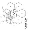
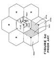
- FIG. 2where conventional sectors are illustrated and FIGS. 3 a and 3 b illustrating the controllable sectors enabled with the use of a smart antenna.
- traffic loads across the three sectors 200vary greatly, with a single sector 201 handling traffic for the office park 211 and most of the residential area 212 .
- the cell's sectors 300 in FIGS. 3 a and 3 bhave been resized and reoriented to the traffic load is more evenly distributed among the three sectors.
- Each sector's beam widthhas been altered to best accommodate the peak traffic load in that sector.
- the narrow sector 301 covering the office park 211maximizes capacity for a high traffic area, while the relatively wide sector 303 covering the water 214 provides adequate capacity for a low-traffic area.
- the sectorscan be redefined to provide narrow sector 303 coverage to the football stadium 215 when a large event is taking place.
- Smart antennasrefer to antennas that spatially steer or switch beams or nulls, or dynamically reallocate available RF channels to different sectors in a base station. In general, they do this as a function of the loading on the base station, or based on the direction of arrival of the RF energy from mobile appliances. The purpose of these functions as discussed above is to extend base station range, improve signal quality, and/or increase the number of users served by the base station. Smart antennas are generally made up of antenna arrays, and accompanying electronics boxes.
- FIG. 4shows the principal system elements of a smart antenna.
- the smart antenna 400typically consists of a sensor array 401 (antenna array), a pattern-forming network 410 and the adaptive processor 413 .
- the pattern-forming network 410 and the adaptive processor 413make up the electronic box referred to earlier.
- the antenna array 401consists of N antennas 402 designed to receive (and transmit) signals.
- the physical arrangement of the array(linear, circular, etc.) is arbitrary, however, the physical arrangement fundamentally dictates the capability of the smart antenna 400 .
- the output of each of the N antenna element 402is fed into the pattern-forming network 410 , where the outputs are processed by filters 411 . These filters determine the directional pattern of the smart antenna.
- the outputs of the filters 411are then summed 412 to form the overall output y(t).
- the complex weights of the filters 411are determined by the adaptive processor 413 .
- Smart antennascan operate on either the forward link, reverse link, or both. Smart antennas can be a part of the base station hardware supplied by the infrastructure vendor, or an appliqué supplied by a third part vendor. In general, the operation of the smart antenna (null/beam steering/switching or channel sector switching) is not known to the rest of the host base station or the wireless infrastructure.
- Network overlay location systemstypically locate a mobile appliance on the traffic channels of a wireless network.
- the systemtypically uses sensors employing techniques of time difference of arrival (TDOA) supplemented with Angle of Arrival (AOA) in some cases to perform a multi-site location computation.
- TDOAtime difference of arrival
- AOAAngle of Arrival
- the traffic channel assignment informationis provided through a separate process, with one option being a wire line interface between the MPC 40 and the GCS 50 ( FIG. 1 ) providing MOBINFO (IS-41 Mobile information) parameters passed by the Mobile Positioning Center (MPC) 40 ( FIG. 1 ) as part of the GPOSREQ (J-STD-036 Geolocation Position Request) message.
- MOBINFOIS-41 Mobile information
- GPOSREQJ-STD-036 Geolocation Position Request
- Geolocation systemslocate the transmitter using the corresponding MOBINFO parameters passed from the MPC 40 .
- information provided to the location system by the MPC on the serving sectormay or may not be accurate.
- the smart antennamay have moved the RF channel from the original serving sector to another to accommodate current traffic needs, or could have spatially steered a beam or null that moves the original coverage of area of a sector to a new geographic area.
- the overall affect of these smart antenna functionsis that the mobile of interest may or may not be in the original geographic area defined by the sector communicated to the location system by the MPC 40 which can frustrate the geo-location process.
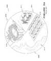
- FIG. 5 ashows a communication system with 7 base stations and their associated overage areas 501 .
- a base station 510is designated to operate in a three-sector mode (A 511 , B 512 , and C 513 ).
- the infrastructure equipment(mobile switch, not shown) contains data that indicates what RF channels are mapped to what sectors at the base station 510 .
- channels u and v, w and x and y and zare mapped (assigned) to sectors A 511 , B 512 and C 513 respectively.
- the sector serving the mobilewould be known by the mobile switch (sector A 511 ) based on the assigned RF channel/traffic channel (channel v).
- the geo-location systemwould task sensors in the vicinity of the serving A sector area, namely sensors in sector 523 of base station 520 , and sector 533 of base station 530 to locate the mobile.
- Other sectorscan also be tasked on their vicinity to the serving sector, however only the two closest are shown for clarity of illustration.
- a smart antennais operating at base station 510 , then the smart antenna can move the assigned RF channel, z from sector C 513 to another sector A 511 through an RF switch in the smart antenna to accommodate extra traffic seen on the A sector 511 for this time of day (perhaps a major commuter route is served by the A sector 511 , and additional RF channels are allocated to serve it by taking channels from the C sector 513 ).
- Prior art geo-location systemsattempt to locate the mobile by tasking sensors around the C sector 513 , since z is mapped to C, and the smart antenna and its dynamic allocation of channels and variations in sectors is invisible to the base station and the MPC.
- the sensors in sector 542 of base station 540 and sector 551 of base station 550 as shown in FIG. 5 bwould be tasked to locate the mobile 500 . Thus a poor or perhaps no location would be estimated because the sensors tasked are not the one in proximity to the actual location of the mobile appliance.
- the RF signals from the mobilemust pass through the smart antenna array and the accompanying electronics. These entities add delay to the time of arrival of the RF when compared to the normal path delay that would be encountered at the base station without a smart antenna present and thus can lead to inaccurate location results when time-based location techniques such as TDOA are used.
- the wireless systemincludes plural base stations and a MPC, each of the base stations include pre-assigned sectors defining a coverage area.
- One of the base stationsincludes a smart antenna.
- the methodincludes the steps of determining the serving sector from the pre-assigned sectors and using a database to determine if the serving sector's base station has a smart antenna.
- the methodinvolves scanning antennas elements of the serving sector's base station, prior to pattern forming, for the target mobile appliance's signal to find the actual sector for the mobile appliance.
- the systemthen tasks sensors in proximity of the actual sector to locate the mobile appliance.
- the host systemincludes a several base stations including sectors defining a coverage area, and one of the base stations employs a smart antenna.
- the host systemalso includes a mobile positioning center which provides the geo-location system with information parameters to assist in the location acquisition of the wireless appliance.
- the methoddetermines a sector of interest from the information parameters and tasks sensors near each sector of the sector of interest base station to locate the mobile appliance.
- the wireless communication systemhaving a network overlay geo-location system including plural base stations and an MPC.
- the base stationshaving assigned channels for each sector representing a coverage area, and one or more of the base stations include smart antennas for adapting the sectors within the coverage area including reassignment of channels.
- the methodentails tasking plural geo-location sensors in the geo-location system to search for the signal and selecting a set of sensors based on the mobile appliance's signal parameters at each sensor and locating the mobile appliance with the set of sensors.
- the methodincluding receiving mobile information from a MPC, including information for determining an assigned sector, and tasking geo-location sensors proximate to a search area to locate the mobile appliance.
- the improvementincludes for each antenna output associated with the assigned sector's base station, measuring a parameter of the mobile appliance's signal; and, selecting the search area based on the measured parameters.
- the methodincluding determining from a database which geo-location sensors are located at base stations with smart antennas; adjusting the measured parameters from geo-location sensors located at base stations with smart antenna; and, determining the location of the mobile appliance from the adjusted measured parameter.
- the systemincludes a base station with a smart antenna, the smart antenna having an antenna array and a pattern-forming network.
- the systemalso has a mobile positioning center in communicational connection with the network overlay geo-location system.
- the sensors of the network overlay geo-location systembeing connected to the smart antenna at an interface between the antenna array and the pattern-forming network.
- the smart antennaincluding an antenna array and a pattern-forming network and the sensors are connected to the smart antenna at an interface between the antenna array and the pattern forming network.
- the methodincludes the steps of: retrieving serving sector information from the mobile position center, determining from a database if the serving sector is at a base station with a smart antenna and switching a network overlay geo-location system to a selected one of two different operating modes based on the determination.
- FIG. 1is an illustration of a standard network overlay geo-location system with host wireless communication system.
- FIG. 2is a representation of a typical base stations sectorized coverage area.
- FIGS. 3 a and 3 bis a representation of a sectorized coverage area of a base station utilizing a smart antenna.
- FIG. 4is a representation of a smart antenna.
- FIG. 5 ais a representation of cells in a communication system, illustrating the selection of proximate sectors.
- FIG. 5 bis a representation of cells in a communication system with base stations using smart antennas switching channel assignments, illustrating the selection of proximate sectors.
- FIG. 5 cis a representation of cells in communication system with base station using smart antennas changing sector beam width and orientation, illustrating the selection of proximate sectors.
- FIG. 6is a representation of a network overlay geo-location system with host wireless communication system according to an embodiment of the disclosed subject matter.
- FIG. 7is a representation of a network overlay geo-location system with host wireless communication system according to another embodiment of the disclosed subject matter.
- FIG. 8is a flow chart of the operation of the geo-location system according to an embodiment of the disclosed subject matter.
- FIG. 9is a representation of cells in a communication system locating a mobile according to the embodiment of FIG. 8 .
- FIG. 10is a flow chart of the operation of a geo-location system according to another embodiment of the disclosed subject matter.
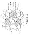
- FIG. 11is a representation of cells in a communication system locating a mobile appliance according to the embodiment of FIG. 10 .
- FIG. 12is a flow chart of the operation of a geo-location system according to yet another embodiment of the disclosed subject matter.
- FIG. 13is a representation of cells in a communication system locating a mobile appliance according to the embodiment of FIG. 12 .
- FIG. 6is an embodiment 600 of a wireless communication system with a network overlay geo-location system that accounts for the sector and channel variations presented by the use of a smart antenna in locating a target mobile appliance.
- the host wireless communication systemincludes a plurality of base stations 601 - 604 and a mobile positioning center (MPC) 605 ( FIG. 1 ).
- MPCmobile positioning center
- One of the base stations 601 in FIG. 6is shown with a smart antenna 610 .
- the smart antenna 610contains the same features with the same reference numerals as described previously in FIG. 4 .
- the network overlay geo-location systemis formed by a central processing unit, GCS 650 and a plurality of sensors ( 621 - 624 ) located at the base stations.
- a configuration database 640which includes the wireless system configuration information, including channel assignment, sector size and sector orientation as originally configured or amended.
- the configuration databasereflects the set parameters, not necessarily the current base station parameter.
- the configuration database 640 in the embodiment of FIG. 6also includes an extra field beyond the prior art. This additional field simply contains information designating which base stations within the communication system have or use smart antennas. This information regarding the presence of smart antennas at the base stations can alternatively be contained in a database accessible to the geo-location system located other than at the GCS, likewise in the embodiment shown, the database need not be contained in the GCS since only access is required.
- the system configuration databasecan also be augmented with a field to indicate which sensors are located at smart antennas, rather than which base stations have smart antennas.
- the information contained in the extra fieldcan be used as a key reference for the geo-location system in determining the manner in which sensors are selected to locate the target mobile appliance. Specifically, this field can be used to select a mode of operation of the geo-location system. In one mode, where no smart antennas are present, the ordinary method of selecting sensors is implemented since the information provided by the MPC and which the selection is based are most likely valid. In another mode the geo-location system proceeds with the selection of neighboring sectors while recognizing the possible reallocation of the sector configuration enabled by the smart antennas and accounting for such possible changes.
- the geo-location sensors 607 or wireless location sensorsare specifically connected to the smart antenna by an interface between the antenna array 401 of the smart antenna 610 and the pattern-forming network 410 with interface 608 .
- the location of the geo-location sensors 621 interface 608 to the smart antenna/base station equipmentensures its antenna feeds are not affected by the dynamic spatial patterns of the smart antenna 610 , while the embodiment shows a single WLS 621 and interface 608 , multiple sensors and interfaces are equally functional, for clarity, a composite sensor is shown. Interfaces that meet these criteria include after the antenna array 401 , or after the antenna array and fixed beam formers 615 or switches (not shown) in the RF chain in the smart antenna 610 .
- both of these interfacesare before the dynamic beam/null/sector steering/switching apparatus (i.e. pattern-forming network 410 ) in the smart antenna 610 .
- the output of the pattern-forming network of a smart antennais indistinguishable in regards to channel assignment and other sector characteristics from the antenna output in conventional fixed channel fixed sector antennas, even though the sector characteristics may be entirely different.
- the embodiment shown in FIG. 6includes a fixed beam former 615 which is commonly used in standard base stations for several known reasons that will not be further expanded here. As stated above the fixed beam former 615 does not act to dynamically change or alter the sector/channel characteristics from that presumed in the system configuration database.
- the embodiment 700 shown in FIG. 7also includes another database or database fields which include time adjustments for sensors attached to smart antennas.
- the additional time delay elements in the RF path between the antenna array 401 and the location sensor (WLS)exist due to the processing in the pattern forming network.
- the sensorsare located in the receive path after the pattern-forming network.
- These time adjustmentsare stored in the auxiliary database 641 and are sensor specific.
- the time delay adjustmentscan be empirically or experimentally determined. In this way, the time delay for these elements can be compensated for in the time difference of arrival calculation.
- the keycan also trigger the execution of other function at the sensors as described below.
- the sensor at the base stations with smart antennascan operate in a mode where the mobile appliance of interest is not located within the sector coverage area as indicated by the tasking parameters, but instead in the sector where it actually resides.
- the unique operation in the network overlay location equipment to accommodate this situationis necessary, so as to not rely on the serving sector information provided when a smart antenna is operating at the base station, but instead to rapidly scan all of the antenna outputs provided to the location system to find the antenna that best receives the mobile in question.
- the sensors in the proximity of the actual mobile's positioncan be switched to the proper antenna elements, and tasked to provide time or angle data on the mobile to determine a position.
- power levelcan be used.
- Existing radio assets and antenna switches in the sensors (WLS)can be used to perform the scanning function.
- FIG. 8is a representative flow chart of the operation of the geo-location system for locating a mobile appliance in a wireless communication system employing smart antenna at one or more of its base stations.
- the MPCgenerates the mobile information, including the serving sector from information provided by the wireless network, and this information is relayed to the geo-location system.
- the geo-location system in block 802accesses a database 803 which includes the extra field that indicates which sectors employ smart antennas.
- the geo-location systemscans antenna elements of all the sectors in the serving sectors base station and may also scan antenna elements in neighboring base stations as shown in block 804 .
- a parametersuch as received signal strength, or a quality metric formed from a cross correlation of known features of the target mobile signal, such as a training sequence pattern, pilot signal or other known data, is estimated or measured for each of the antennas scan in block 805 .
- the geo-location system using the received signal strengths or other suitable signal parameterdetermines or selects the actual geographic sector serving the mobile appliance as indicated in Block 806 and determines sector sensors (WLS) in the vicinity of the actual serving sector in block 807 which are tasked to determine the time of arrival of the mobile appliances signal in block 808 .
- WLSsector sensors
- the geo-location systemlocates the mobile appliances by the time-of-arrival at the selected sector sensors using time-difference-of-arrival or angle-of-arrival in blocks 809 , 810 . Since the actual sector is determined and used to identify sensors in the vicinity, the accuracy of the information provided by the MPC will not affect the accuracy of the determined location.
- the mobile appliance's signalis typically a traffic channel, however, reverse pilot signals available in 3rd Generation CDMA systems can also be used in the geo-location system.
- FIG. 9is a representation of the process used to address the situation presented in FIG. 5 b .
- a smart antenna operating at base station 910reassigns RF channel, z from sector C 913 to sector A 911 through an RF switch in the smart antenna to accommodate extra traffic seen on the A sector 911 .
- the MPCrelays mobile information to the geo-location system, including information designating sector C 913 as the serving sectors.
- the geo-location systemaccesses a database, or a field in the system configuration database indicating the serving sector C 913 is at a base station with a smart antenna.
- the geo-location systemscans all the antenna elements of sectors 911 , 912 and 913 and measures the received signal strength of the mobile signal.
- the measurementsindicate the strongest signal from an antenna element located in the A sector 911 and thus tasks the sensors (WLS) in sectors proximate to the actual sector A 911 , namely the sensor at sector 932 of base station 930 and sector 923 of base station 920 to record the time of arrival of the mobiles signal.
- WLSsensors
- Other sensors in the vicinity of the actual sectorcan also be tasked to locate the mobile appliance, however are not shown for clarity.
- the geo-location systemuses these times of arrival to calculate time difference of arrival, angle of arrival or other known means to locate the mobile appliance 900 .
- the results of the described methodwhen compared with that shown in FIG. 5B is clearly advantageous. The similarly advantageous sensor selection and geo-location would result if the operation was applied to the example demonstrated in FIG. 5 c.
- FIG. 10is a representative flow chart of an embodiment of the disclosed subject matter.
- the MPCprovides mobile information including a sector of interest for the targeted mobile appliance.
- the database or database field 1003is accessed to determine whether the sector of interest's base station uses a smart antenna in block 1002 .
- the geo-location systemselects sector sensors proximate to all of the sectors associated with the sector of interest's base station. The geo-location system then uses the time of arrival at the selected sector sensors to determine the location of the mobile appliance using TDOA or AOA or other known methods.
- FIG. 11shows the selection of sector sensors in neighboring base stations for the method shown in FIG. 10 .
- FIG. 11duplicates the smart antenna scenario described with respect to FIG. 5 b and FIG. 9 previously.
- the geo-location systemupon identifying sector 1111 as the sector of interest for mobile appliance 1100 tasks all the sector sensors proximate to each sector (A, B and C) of the sector or interest's base station 1110 to locate the mobile appliances signal.
- sensors located in sectors 1123 , 1132 , 1142 , 1151 , 1161 , and 1173 of base stations 1120 , 1130 , 1140 , 1150 , 1160 and 1170respectively are used to locate the mobile stations.
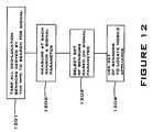
- FIG. 12is a flow chart of another embodiment of the disclosed subject manner.
- the geo-location systemtasks sensors at more than one base stations in the communication system to search for the mobiles signals.
- the tasked sensorsmeasure received signal strength of the mobile signal, block 1202 , and the geo-location system selects a set of the sensors in block 1203 to locate the mobile based on the measured received strength of the signal. In this manner, the actual sector of the mobile appliance is not needed.
- the sensors selected to locate the mobileare selected on the basis of their actual ability to receive the signal, therefore their vicinity is irrelevant.
- the geo-location systemuses TDOA, and/or AOA of the signal at the selected sensors to locate the mobile in block 1204 .
- FIG. 13shows a representation of the operation of the location system for FIG. 12 in the scenario presented in FIG. 5 b.
- each of the sectors 1323 , 1332 , 1342 , 1351 , 1361 , 1373searches for the signal.
- Sectors 1332 , 1342 , 1361 and 1373received the signal at a sufficient high signal strength and thus are identified and participate in the determination of a location of the mobile 1300 .
- sector 1323would normally also be selected, however, because of other factors such as geography, or antenna height or localized interferers, the signal was not received with a high signal strength. Nonetheless, the geo-location system, since it does not rely on the sector information from the MPC, was able to locate the mobile 1300 .
Landscapes
- Engineering & Computer Science (AREA)
- Computer Networks & Wireless Communication (AREA)
- Signal Processing (AREA)
- Physics & Mathematics (AREA)
- Radar, Positioning & Navigation (AREA)
- Remote Sensing (AREA)
- General Physics & Mathematics (AREA)
- Quality & Reliability (AREA)
- Electromagnetism (AREA)
- Mobile Radio Communication Systems (AREA)
- Position Fixing By Use Of Radio Waves (AREA)
- Variable-Direction Aerials And Aerial Arrays (AREA)
- Radar Systems Or Details Thereof (AREA)
- Radio Transmission System (AREA)
Abstract
Description
Claims (51)
Priority Applications (1)
| Application Number | Priority Date | Filing Date | Title |
|---|---|---|---|
| US10/531,040US7945212B2 (en) | 2002-10-16 | 2003-10-16 | Network overlay geo-location system with smart antennas and method of operation |
Applications Claiming Priority (3)
| Application Number | Priority Date | Filing Date | Title |
|---|---|---|---|
| US41834202P | 2002-10-16 | 2002-10-16 | |
| US10/531,040US7945212B2 (en) | 2002-10-16 | 2003-10-16 | Network overlay geo-location system with smart antennas and method of operation |
| PCT/US2003/032578WO2004036934A1 (en) | 2002-10-16 | 2003-10-16 | Network overlay geo-location system with smart antennas |
Publications (2)
| Publication Number | Publication Date |
|---|---|
| US20100178929A1 US20100178929A1 (en) | 2010-07-15 |
| US7945212B2true US7945212B2 (en) | 2011-05-17 |
Family
ID=32107918
Family Applications (7)
| Application Number | Title | Priority Date | Filing Date |
|---|---|---|---|
| US10/531,044Expired - LifetimeUS7429951B2 (en) | 2002-10-16 | 2003-10-16 | System and method for enhancing the accuracy of a location estimate |
| US10/531,039Expired - LifetimeUS7379757B2 (en) | 2002-10-16 | 2003-10-16 | System and method for estimating the multi-path delays in a signal using a spatially blind antenna array |
| US10/531,040Expired - Fee RelatedUS7945212B2 (en) | 2002-10-16 | 2003-10-16 | Network overlay geo-location system with smart antennas and method of operation |
| US10/531,042Expired - Fee RelatedUS7200392B2 (en) | 2002-10-16 | 2003-10-16 | Wireless communication network measurement data collection using infrastructure overlay-based handset location systems |
| US10/531,041Expired - LifetimeUS7627327B2 (en) | 2002-10-16 | 2003-10-16 | Network overlay location system and method for air interface with frequency hopping |
| US12/078,471Expired - LifetimeUS7778608B2 (en) | 2002-10-16 | 2008-03-31 | System and method for estimating the multi-path delays in a signal using a spatially blind antenna array |
| US12/122,942Expired - Fee RelatedUS7911384B2 (en) | 2002-10-16 | 2008-05-19 | System and method for enhancing the accuracy of a location estimate |
Family Applications Before (2)
| Application Number | Title | Priority Date | Filing Date |
|---|---|---|---|
| US10/531,044Expired - LifetimeUS7429951B2 (en) | 2002-10-16 | 2003-10-16 | System and method for enhancing the accuracy of a location estimate |
| US10/531,039Expired - LifetimeUS7379757B2 (en) | 2002-10-16 | 2003-10-16 | System and method for estimating the multi-path delays in a signal using a spatially blind antenna array |
Family Applications After (4)
| Application Number | Title | Priority Date | Filing Date |
|---|---|---|---|
| US10/531,042Expired - Fee RelatedUS7200392B2 (en) | 2002-10-16 | 2003-10-16 | Wireless communication network measurement data collection using infrastructure overlay-based handset location systems |
| US10/531,041Expired - LifetimeUS7627327B2 (en) | 2002-10-16 | 2003-10-16 | Network overlay location system and method for air interface with frequency hopping |
| US12/078,471Expired - LifetimeUS7778608B2 (en) | 2002-10-16 | 2008-03-31 | System and method for estimating the multi-path delays in a signal using a spatially blind antenna array |
| US12/122,942Expired - Fee RelatedUS7911384B2 (en) | 2002-10-16 | 2008-05-19 | System and method for enhancing the accuracy of a location estimate |
Country Status (3)
| Country | Link |
|---|---|
| US (7) | US7429951B2 (en) |
| AU (5) | AU2003277379A1 (en) |
| WO (5) | WO2004036525A2 (en) |
Cited By (4)
| Publication number | Priority date | Publication date | Assignee | Title |
|---|---|---|---|---|
| US20110087639A1 (en)* | 2009-10-12 | 2011-04-14 | Motorola, Inc. | Method and apparatus for automatically ensuring consistency among multiple spectrum databases |
| US20110117834A1 (en)* | 2007-05-22 | 2011-05-19 | Telstra Corporation Limited | Repeater system for extended cell coverage |
| US20120009949A1 (en)* | 2009-05-12 | 2012-01-12 | Andrew, Llc | System and method for locating wimax or lte subscriber stations |
| US9173058B2 (en) | 2008-05-23 | 2015-10-27 | Commscope Technologies Llc | System and method for locating WiMAX or LTE subscriber stations |
Families Citing this family (115)
| Publication number | Priority date | Publication date | Assignee | Title |
|---|---|---|---|---|
| US7429951B2 (en)* | 2002-10-16 | 2008-09-30 | Andrew Corporation | System and method for enhancing the accuracy of a location estimate |
| EP1614238A2 (en)* | 2003-04-17 | 2006-01-11 | QUALCOMM Incorporated | Method and apparatus for determining repeater use in wireless communications |
| US7623872B2 (en)* | 2003-06-24 | 2009-11-24 | Andrew Corporation | Method for sparse network deployment accuracy enhancements |
| JP2005039649A (en)* | 2003-07-17 | 2005-02-10 | Hitachi Ltd | Base station apparatus and radio communication system |
| ATE360969T1 (en)* | 2003-09-16 | 2007-05-15 | Research In Motion Ltd | METHOD FOR PERFORMING RADIATION TESTS OF WIRELESS DEVICES |
| DE10345224B4 (en)* | 2003-09-29 | 2005-12-01 | Siemens Ag | Method for position estimation of a subscriber station of a radio communication system and network device |
| WO2005060669A2 (en)* | 2003-12-19 | 2005-07-07 | Kennedy Joseph P | E-otd augmentation to u-tdoa location system |
| US7409444B2 (en)* | 2004-05-10 | 2008-08-05 | Bdna Corporation | Method and apparatus for managing business cell phone usage |
| CN100433878C (en)* | 2004-07-27 | 2008-11-12 | 中兴通讯股份有限公司 | Wired connection method for measuring time period of CDMA mobile terminal in stood by state |
| KR100676506B1 (en)* | 2004-09-20 | 2007-01-31 | 김기종 | F Wireless Radio Environment Measurement Method |
| US7277712B2 (en)* | 2004-11-17 | 2007-10-02 | At&T Mobility Ii, Llc | Method and system for providing location information for emergency services |
| US8364185B2 (en)* | 2005-04-18 | 2013-01-29 | Samsung Electronics Co., Ltd. | Method and system for synchronizing a clock for an adjacent network to a clock for an overlay network |
| EP1882374A4 (en)* | 2005-05-17 | 2008-05-21 | Andrew Corp | Method and apparatus for determining coupled path loss |
| US7630327B2 (en)* | 2005-07-13 | 2009-12-08 | Andrew Llc | Method for data maintenance and integration including interpolation |
| US7529236B2 (en)* | 2005-08-15 | 2009-05-05 | Technocom Corporation | Embedded wireless location validation benchmarking systems and methods |
| US20070117573A1 (en)* | 2005-11-04 | 2007-05-24 | Kennedy Joseph P Jr | System and method for generating geocoded data for network optimization under different network architectures and location technology conditions |
| US7535420B2 (en)* | 2005-12-22 | 2009-05-19 | L-3 Communications Integrated Systems L.P. | Method and apparatus for signal tracking utilizing universal algorithm |
| US7456788B2 (en)* | 2005-12-22 | 2008-11-25 | L-3 Communications Integrated Systems L.P. | Method and apparatus for reducing geolocation ambiguity in signal tracking |
| US7551138B2 (en)* | 2005-12-22 | 2009-06-23 | L3 Communications Integrated Systems, L.P. | Method and apparatus for signal tracking utilizing universal algorithm |
| US8588220B2 (en)* | 2005-12-30 | 2013-11-19 | L-3 Communications Corporation | Method and apparatus for mitigating port swapping during signal tracking |
| US7734249B1 (en)* | 2006-03-01 | 2010-06-08 | Sprint Spectrum L.P. | Method and system for reporting usage of a repeater in wireless communications |
| EP1835774A1 (en)* | 2006-03-13 | 2007-09-19 | Siemens Aktiengesellschaft | Method and node for distributing information to a plurality of nodes in a communications network |
| GB0607864D0 (en)* | 2006-04-20 | 2006-05-31 | Ubisense Ltd | Calibration Of A Location System |
| US8000701B2 (en)* | 2006-05-16 | 2011-08-16 | Andrew, Llc | Correlation mechanism to communicate in a dual-plane architecture |
| US8000702B2 (en)* | 2006-05-16 | 2011-08-16 | Andrew, Llc | Optimizing location services performance by combining user plane and control plane architectures |
| US8019339B2 (en) | 2006-05-16 | 2011-09-13 | Andrew Llc | Using serving area identification in a mixed access network environment |
| US7574221B2 (en) | 2006-08-03 | 2009-08-11 | Ntt Docomo, Inc. | Method for estimating jointly time-of-arrival of signals and terminal location |
| JP4952135B2 (en)* | 2006-08-17 | 2012-06-13 | 富士通株式会社 | Wireless terminal, relay station, wireless base station, and communication method |
| US8873585B2 (en) | 2006-12-19 | 2014-10-28 | Corning Optical Communications Wireless Ltd | Distributed antenna system for MIMO technologies |
| US7515104B2 (en)* | 2007-01-23 | 2009-04-07 | The Boeing Company | Structured array geolocation |
| US7471245B2 (en)* | 2007-01-31 | 2008-12-30 | L3 Communications Integrated Systems, L.P. | Method and apparatus for estimating geolocations |
| EP2118810B1 (en) | 2007-02-05 | 2012-08-15 | Andrew Corporation | System and method for optimizing location estimate of mobile unit |
| CN100466554C (en)* | 2007-02-08 | 2009-03-04 | 华为技术有限公司 | Communication adaptation layer system and method for acquiring network element information |
| US20080191941A1 (en)* | 2007-02-12 | 2008-08-14 | Mobileaccess Networks Ltd. | Indoor location determination |
| KR100896680B1 (en)* | 2007-04-13 | 2009-05-14 | 에스케이 텔레콤주식회사 | Method and system for providing network-based location positioning to mobile communication terminals according to location using G-pCell database |
| US7933610B2 (en) | 2007-05-21 | 2011-04-26 | Andrew Llc | Method and apparatus to select an optimum site and/or sector to provide geo-location data |
| US8032183B2 (en)* | 2007-07-16 | 2011-10-04 | Alcatel Lucent | Architecture to support network-wide multiple-in-multiple-out wireless communication |
| US8170585B2 (en) | 2007-11-14 | 2012-05-01 | Andrew, Llc | Ranging in UMTS networks |
| US8447319B2 (en)* | 2007-11-15 | 2013-05-21 | Andrew Llc | System and method for locating UMTS user equipment using measurement reports |
| TWI358925B (en)* | 2007-12-06 | 2012-02-21 | Ind Tech Res Inst | System and method for locating a mobile node in a |
| US7800530B2 (en) | 2007-12-07 | 2010-09-21 | Andrew, Llc | Method and system for providing assistance data for A-GPS location of handsets in wireless networks |
| US8140076B2 (en)* | 2007-12-17 | 2012-03-20 | Motorola Mobility, Inc. | Method for facilitating a mobile station to perform a fast handoff |
| US8718712B2 (en)* | 2008-03-24 | 2014-05-06 | Nec Corporation | Base station configuration design support system, and base station configuration design support method and program |
| US8213955B2 (en) | 2008-05-01 | 2012-07-03 | Andrew, Llc | Network measurement report caching for location of mobile devices |
| US8193987B2 (en)* | 2008-08-25 | 2012-06-05 | DRS Soneticom. Inc. | Apparatus and method for determining signal quality in a geolocation system |
| US8073463B2 (en) | 2008-10-06 | 2011-12-06 | Andrew, Llc | System and method of UMTS UE location using uplink dedicated physical control channel and downlink synchronization channel |
| US8762519B2 (en)* | 2008-10-28 | 2014-06-24 | Andrew Llc | System and method for providing location services for multiple access networks from a single location server |
| US8035557B2 (en)* | 2008-11-24 | 2011-10-11 | Andrew, Llc | System and method for server side detection of falsified satellite measurements |
| US8380222B2 (en) | 2008-11-26 | 2013-02-19 | Andrew Llc | System and method for multiple range estimation location |
| US8249622B2 (en) | 2008-11-26 | 2012-08-21 | Andrew, Llc | System and method for multiple range estimation location |
| US8160609B2 (en)* | 2008-11-26 | 2012-04-17 | Andrew Llc | System and method for multiple range estimation location |
| US7916071B2 (en) | 2008-12-23 | 2011-03-29 | Andrew, Llc | System and method for determining a reference location of a mobile device |
| US8391884B2 (en) | 2009-03-26 | 2013-03-05 | Andrew Llc | System and method for managing created location contexts in a location server |
| US8416710B2 (en) | 2009-03-30 | 2013-04-09 | At&T Mobility Ii Llc | Indoor competitive survey of wireless networks |
| US8290510B2 (en)* | 2009-06-11 | 2012-10-16 | Andrew Llc | System and method for SUPL held interworking |
| US8787942B2 (en) | 2009-08-05 | 2014-07-22 | Andrew Llc | System and method for hybrid location in an LTE network |
| US8217832B2 (en)* | 2009-09-23 | 2012-07-10 | Andrew, Llc | Enhancing location accuracy using multiple satellite measurements based on environment |
| US8289210B2 (en) | 2009-10-15 | 2012-10-16 | Andrew Llc | Location measurement acquisition adaptive optimization |
| US8188920B2 (en) | 2009-10-15 | 2012-05-29 | Andrew, Llc | Location measurement acquisition optimization with Monte Carlo simulation |
| US8565096B2 (en) | 2009-10-18 | 2013-10-22 | Locus Location Systems, Llc | Method and system for analyzing radio performance during over-the-air operation |
| US8600371B2 (en) | 2009-10-18 | 2013-12-03 | Locus Location Systems Llc | Method and system for diagnosing radio performance during functional over-the-air operation |
| US9331798B2 (en)* | 2010-01-08 | 2016-05-03 | Commscope Technologies Llc | System and method for mobile location by proximity detection |
| KR101637110B1 (en)* | 2010-01-08 | 2016-07-06 | 인터디지탈 패튼 홀딩스, 인크 | Method and apparatus for collecting and transmitting data |
| US8718673B2 (en) | 2010-05-21 | 2014-05-06 | Maple Acquisition Llc | System and method for location assurance of a mobile device |
| US8810452B2 (en)* | 2010-05-24 | 2014-08-19 | Trueposition, Inc. | Network location and synchronization of peer sensor stations in a wireless geolocation network |
| JP5679410B2 (en)* | 2010-05-27 | 2015-03-04 | 京セラ株式会社 | Wireless communication system, wireless base station, and communication control method |
| US9638786B2 (en)* | 2010-07-22 | 2017-05-02 | Mobixity, Inc. | System and method for locating a mobile terminal in a finite location |
| US8958754B2 (en) | 2010-09-29 | 2015-02-17 | Andrew, Llc | System and method for sub-coherent integration for geo-location using weak or intermittent signals |
| US8489122B2 (en) | 2010-12-09 | 2013-07-16 | Andrew Llc | System and method for total flight time ratio pattern matching |
| US9933525B2 (en) | 2010-12-30 | 2018-04-03 | Telcom Ventures, Llc | Systems and methods for a terrestrial-based positioning beacon network |
| US8620239B2 (en)* | 2011-01-14 | 2013-12-31 | Qualcomm Incorporated | Dynamic DC-offset determination for proximity sensing |
| WO2012112555A1 (en) | 2011-02-14 | 2012-08-23 | Andrew Llc | Method for mobile location by dynamic clustering |
| US20120269095A1 (en)* | 2011-04-20 | 2012-10-25 | Nokia Siemens Networks Oy | Method and apparatus for providing a network search function |
| US8774837B2 (en) | 2011-04-30 | 2014-07-08 | John Anthony Wright | Methods, systems and apparatuses of emergency vehicle locating and the disruption thereof |
| US8825042B2 (en) | 2011-05-12 | 2014-09-02 | Lows Location Systems, LLC | Network diagnostic system for analyzing the performance of a radio network during functional over-the-air operation |
| CN102223191B (en)* | 2011-06-02 | 2014-11-05 | 电信科学技术研究院 | Method and equipment for acquiring idle spectrum |
| US9715001B2 (en) | 2011-06-13 | 2017-07-25 | Commscope Technologies Llc | Mobile location in a remote radio head environment |
| EP2595436B1 (en)* | 2011-11-15 | 2016-03-16 | Telefonaktiebolaget LM Ericsson (publ) | A method and a network node for localization of a user equipment |
| US9413805B2 (en)* | 2011-12-15 | 2016-08-09 | Geocomply Global Inc. | Geolocation engine |
| US9423508B2 (en) | 2012-01-12 | 2016-08-23 | Commscope Technologies Llc | Autonomous Transmit Chain Delay Measurements |
| US8897813B2 (en) | 2012-02-03 | 2014-11-25 | Andrew Llc | LTE user equipment positioning system and method |
| EP2832012A1 (en) | 2012-03-30 | 2015-02-04 | Corning Optical Communications LLC | Reducing location-dependent interference in distributed antenna systems operating in multiple-input, multiple-output (mimo) configuration, and related components, systems, and methods |
| CN104335631B (en)* | 2012-04-09 | 2018-06-19 | 瑞典爱立信有限公司 | For enhancing the method and apparatus of network positions measurement performance by management uncertain measurement opportunity |
| US9913147B2 (en) | 2012-10-05 | 2018-03-06 | Andrew Wireless Systems Gmbh | Capacity optimization sub-system for distributed antenna system |
| CN105308876B (en) | 2012-11-29 | 2018-06-22 | 康宁光电通信有限责任公司 | Remote unit antennas in distributing antenna system combines |
| US9220022B2 (en)* | 2013-03-13 | 2015-12-22 | Alcatel Lucent | LTE user presence detection for small cell placement |
| US9686765B2 (en) | 2013-04-12 | 2017-06-20 | Hewlett Packard Enterprise Development Lp | Determining an angle of direct path of a signal |
| EP2984882A4 (en)* | 2013-04-12 | 2016-11-09 | Hewlett Packard Entpr Dev Lp | DETERMINING THE LOCATION OF A MOBILE DEVICE |
| US20140333482A1 (en)* | 2013-05-10 | 2014-11-13 | Telcom Ventures, Llc | Methods of position-location determination using a high-confidence range, and related systems and devices |
| EP2852207B1 (en)* | 2013-07-22 | 2016-10-26 | Huawei Technologies Co., Ltd. | Fault diagnosis method and apparatus for wireless network |
| US9521520B2 (en)* | 2013-11-13 | 2016-12-13 | Cisco Technology, Inc. | Distributed-input OFDM angle-of-arrival scheme for location determination |
| DE102013021966A1 (en)* | 2013-12-20 | 2015-06-25 | Giesecke & Devrient Gmbh | A method and apparatus for providing a subscription for communication over a cellular network |
| US9270493B2 (en)* | 2014-02-26 | 2016-02-23 | Telefonaktiebolaget L M Ericsson (Publ) | Scalable estimation ring |
| US9525472B2 (en) | 2014-07-30 | 2016-12-20 | Corning Incorporated | Reducing location-dependent destructive interference in distributed antenna systems (DASS) operating in multiple-input, multiple-output (MIMO) configuration, and related components, systems, and methods |
| US9967003B2 (en) | 2014-11-06 | 2018-05-08 | Commscope Technologies Llc | Distributed antenna system with dynamic capacity allocation and power adjustment |
| US9706514B2 (en) | 2014-12-02 | 2017-07-11 | Cisco Technology, Inc. | Wideband angle-of-arrival location determination using bandwidth partitioning |
| US9729267B2 (en) | 2014-12-11 | 2017-08-08 | Corning Optical Communications Wireless Ltd | Multiplexing two separate optical links with the same wavelength using asymmetric combining and splitting |
| US9719787B2 (en)* | 2015-02-26 | 2017-08-01 | Invensense, Inc. | Method and system for multiple pass smoothing |
| US9363784B1 (en) | 2015-04-30 | 2016-06-07 | Mist Systems Inc. | Methods and apparatus relating to the use of real and/or virtual beacons |
| US9743254B2 (en) | 2015-04-30 | 2017-08-22 | Mist Systems, Inc. | Methods and apparatus relating to the use of received signals to determine wireless terminal location and/or refine location determination models |
| US9967803B2 (en) | 2015-04-30 | 2018-05-08 | Mist Systems, Inc. | Dynamic virtual beacon methods and apparatus |
| US10219166B2 (en) | 2015-04-30 | 2019-02-26 | Mist Systems, Inc. | Methods and apparatus for generating, transmitting and/or using beacons |
| US20160327628A1 (en)* | 2015-05-07 | 2016-11-10 | Alcatel-Lucent Usa Inc. | Method And Apparatus For Determining Non-Line Of Sight Bias Estimation |
| US9848301B2 (en) | 2015-11-20 | 2017-12-19 | At&T Intellectual Property I, L.P. | Facilitation of mobile device geolocation |
| US9998876B2 (en) | 2016-07-27 | 2018-06-12 | At&T Intellectual Property I, L.P. | Inferring user equipment location data based on sector transition |
| CA2988895A1 (en)* | 2016-12-16 | 2018-06-16 | Comcast Cable Communications, Llc | Systems and methods for improved geolocation in a low power wide area network |
| US10330770B2 (en) | 2017-11-09 | 2019-06-25 | Cisco Technology, Inc. | Channel estimation in OFDMA for switched antenna array based angle-of-arrival location |
| WO2020043592A1 (en) | 2018-08-27 | 2020-03-05 | Signify Holding B.V. | Determining a suitability of network nodes for rf-based presence and/or location detection |
| US10705178B2 (en)* | 2018-10-03 | 2020-07-07 | Bastille Networks, Inc. | Localization calibration and refinement in high-speed mobile wireless systems |
| US11188493B2 (en)* | 2019-01-18 | 2021-11-30 | Tektronix, Inc. | Bus decode and triggering on digital down converted data in a test and measurement instrument |
| US11902874B2 (en)* | 2019-02-15 | 2024-02-13 | Signify Holding B.V. | Determining a network route which avoids nodes with a RF-based presence and/or location detection function |
| EP3973726A4 (en)* | 2019-05-20 | 2023-05-31 | Saankhya Labs Pvt. Ltd. | Radio mapping architecture for applying machine learning techniques to wireless radio access networks |
| CN111896914B (en)* | 2020-04-10 | 2025-08-01 | 中兴通讯股份有限公司 | Co-location method, device, equipment and storage medium |
| US11860289B2 (en) | 2021-09-14 | 2024-01-02 | At&T Intellectual Property I, L.P. | Moving user equipment geolocation |
| US11863968B2 (en)* | 2021-09-14 | 2024-01-02 | At&T Intellectual Property I, L.P. | Static user equipment geolocation |
Citations (28)
| Publication number | Priority date | Publication date | Assignee | Title |
|---|---|---|---|---|
| US4783744A (en) | 1986-12-08 | 1988-11-08 | General Dynamics, Pomona Division | Self-adaptive IRU correction loop design interfacing with the target state estimator for multi-mode terminal handoff |
| US5317323A (en) | 1993-03-05 | 1994-05-31 | E-Systems, Inc. | Passive high accuracy geolocation system and method |
| US5465289A (en) | 1993-03-05 | 1995-11-07 | E-Systems, Inc. | Cellular based traffic sensor system |
| US5506863A (en) | 1993-08-25 | 1996-04-09 | Motorola, Inc. | Method and apparatus for operating with a hopping control channel in a communication system |
| US5870029A (en) | 1996-07-08 | 1999-02-09 | Harris Corporation | Remote mobile monitoring and communication system |
| US6144711A (en) | 1996-08-29 | 2000-11-07 | Cisco Systems, Inc. | Spatio-temporal processing for communication |
| US6188351B1 (en) | 1998-08-13 | 2001-02-13 | Ericsson Inc. | Method for improving signal acquistion in a global positioning system receiver |
| US6212391B1 (en) | 1997-12-01 | 2001-04-03 | Motorola, Inc. | Method for positioning gsm mobile station |
| US6295455B1 (en) | 1999-06-11 | 2001-09-25 | Telefonaktiebolaget Lm Ericsson (Publ) | Methods and arrangements for locating a mobile telecommunications station |
| US6311043B1 (en) | 1998-10-27 | 2001-10-30 | Siemens Aktiengesellschaft | Method and measurement configuration for measuring the characteristics of radio channels |
| US6334059B1 (en) | 1999-01-08 | 2001-12-25 | Trueposition, Inc. | Modified transmission method for improving accuracy for e-911 calls |
| US20020094821A1 (en) | 2000-12-11 | 2002-07-18 | Kennedy Joseph P. | Pseudolite positioning system and method |
| US6470195B1 (en) | 2000-10-31 | 2002-10-22 | Raytheon Company | Method and apparatus for modeling a smart antenna in a network planning tool |
| US6477161B1 (en) | 1998-12-21 | 2002-11-05 | Nortel Networks Limited | Downlink beamforming approach for frequency division duplex cellular systems |
| US6501955B1 (en) | 2000-06-19 | 2002-12-31 | Intel Corporation | RF signal repeater, mobile unit position determination system using the RF signal repeater, and method of communication therefor |
| US6553322B1 (en) | 1999-09-29 | 2003-04-22 | Honeywell International Inc. | Apparatus and method for accurate pipeline surveying |
| US20030190919A1 (en) | 2000-08-22 | 2003-10-09 | Jarko Niemenmaa | Method for positioning a mobile station |
| US20040043775A1 (en) | 2002-08-29 | 2004-03-04 | Kennedy Joseph P. | Tasking and reporting method and implementation for wireless appliance location systems |
| US6782264B2 (en) | 1999-01-08 | 2004-08-24 | Trueposition, Inc. | Monitoring of call information in a wireless location system |
| US6834234B2 (en) | 2000-11-22 | 2004-12-21 | Trimble Navigation, Limited | AINS land surveyor system with reprocessing, AINS-LSSRP |
| US6845240B2 (en) | 2000-12-11 | 2005-01-18 | Grayson Wireless | System and method for analog cellular radio geolocation |
| US6922170B2 (en) | 2002-01-24 | 2005-07-26 | Motorola, Inc. | Methods and apparatus for determining a direction of arrival in a wireless communication system |
| US20080107155A1 (en)* | 2004-02-02 | 2008-05-08 | Andrew Corporation | Method for calibrating an aoa location system for all frequencies in a frequency hopping signal |
| US20080194207A1 (en)* | 2002-10-16 | 2008-08-14 | Andrew Corporation | System and method for estimating the multi-path delays in a signal using a spatially blind antenna array |
| US20080200184A1 (en)* | 2003-01-31 | 2008-08-21 | Kennedy Joseph P | Method for angle of arrival determination on frequency hopping air interfaces |
| US20080293435A1 (en)* | 2007-05-21 | 2008-11-27 | George Maher | Method and apparatus to select an optimum site and/or sector to provide geo-location data |
| US20090186632A1 (en)* | 2002-10-16 | 2009-07-23 | Kennedy Jr Joseph P | System and method of operation for network overlay geolocation sysem with repeaters |
| US20090286551A1 (en)* | 2003-12-19 | 2009-11-19 | Kennedy Joseph P | E-otd augmentation to u-tdoa location system |
Family Cites Families (29)
| Publication number | Priority date | Publication date | Assignee | Title |
|---|---|---|---|---|
| US190919A (en)* | 1877-05-15 | Improvement in effluvia-ejectors for water-closets | ||
| US94821A (en)* | 1869-09-14 | Improvement in water-wheels | ||
| US43775A (en)* | 1864-08-09 | Improvement in construction of round and half-round files | ||
| US531732A (en)* | 1895-01-01 | Machine for manufacturing plate-glass | ||
| US3975731A (en)* | 1974-12-10 | 1976-08-17 | Grumman Aerospace Corporation | Airborne positioning system |
| US4144571A (en)* | 1977-03-15 | 1979-03-13 | E-Systems, Inc. | Vehicle guidance system |
| US4520445A (en)* | 1981-03-30 | 1985-05-28 | E-Systems, Inc. | Method of determining the position and velocity of a vehicle |
| US4954837A (en)* | 1989-07-20 | 1990-09-04 | Harris Corporation | Terrain aided passive range estimation |
| JP2751768B2 (en)* | 1991-12-18 | 1998-05-18 | 住友化学工業株式会社 | Fiber-reinforced thermoplastic resin molded article and molding method thereof |
| JP2630200B2 (en) | 1993-06-07 | 1997-07-16 | 日本電気株式会社 | Orientation measuring method and apparatus |
| US5960355A (en)* | 1996-02-16 | 1999-09-28 | Telefonaktiebolaget Lm Ericsson | Method and an arrangement relating to telecommunication systems |
| US7714778B2 (en)* | 1997-08-20 | 2010-05-11 | Tracbeam Llc | Wireless location gateway and applications therefor |
| FR2771517B1 (en)* | 1997-11-27 | 2001-12-14 | Dassault Electronique | ELECTRO-OPTICAL DEVICE, PARTICULARLY FOR OPTICAL DISTRIBUTION |
| US6468814B1 (en)* | 1998-07-24 | 2002-10-22 | Leybold Inficon, Inc. | Detection of nontransient processing anomalies in vacuum manufacturing process |
| US6198935B1 (en)* | 1998-11-17 | 2001-03-06 | Ericsson Inc. | System and method for time of arrival positioning measurements based upon network characteristics |
| US6166691A (en) | 1998-12-21 | 2000-12-26 | Telefonaktiebolaget Lm Ericsson (Publ) | Self-calibrating reference terminal |
| US6298092B1 (en)* | 1999-12-15 | 2001-10-02 | Iospan Wireless, Inc. | Methods of controlling communication parameters of wireless systems |
| US6377819B1 (en)* | 2000-04-06 | 2002-04-23 | Iospan Wireless, Inc. | Wireless communication system using joined transmit and receive processing |
| US7006821B2 (en)* | 2000-12-04 | 2006-02-28 | Denso Corporation | Method and apparatus for dynamically determining a mobile station's active set during a connection rescue procedure |
| US6920329B2 (en)* | 2001-01-16 | 2005-07-19 | Allen Telecom | Method and system for applying wireless geolocation technology |
| US7715849B2 (en)* | 2001-02-28 | 2010-05-11 | Nokia Corporation | User positioning |
| GB2373966B (en)* | 2001-03-30 | 2003-07-09 | Toshiba Res Europ Ltd | Mode monitoring & identification through distributed radio |
| US6570529B2 (en)* | 2001-05-24 | 2003-05-27 | Lucent Technologies Inc. | Autonomous calibration of a wireless-global positioning system |
| US6560532B2 (en)* | 2001-05-25 | 2003-05-06 | Regents Of The University Of California, The | Method and system for electronically determining dynamic traffic information |
| US6832090B2 (en)* | 2001-09-10 | 2004-12-14 | Qualcomm Incorporated | System and method for identification of transmitters with limited information |
| US6871077B2 (en) | 2001-10-09 | 2005-03-22 | Grayson Wireless | System and method for geolocating a wireless mobile unit from a single base station using repeatable ambiguous measurements |
| US7623824B2 (en)* | 2002-12-16 | 2009-11-24 | Nokia Corporation | Broadcast media bookmarks |
| US7244175B2 (en)* | 2002-08-29 | 2007-07-17 | De La Rue Cash Systems Inc. | Coin recycling machine and method |
| US6996392B2 (en)* | 2002-09-03 | 2006-02-07 | Trueposition, Inc. | E911 overlay solution for GSM, for use in a wireless location system |
- 2003
- 2003-10-16USUS10/531,044patent/US7429951B2/ennot_activeExpired - Lifetime
- 2003-10-16WOPCT/US2003/032585patent/WO2004036525A2/enactiveSearch and Examination
- 2003-10-16USUS10/531,039patent/US7379757B2/ennot_activeExpired - Lifetime
- 2003-10-16AUAU2003277379Apatent/AU2003277379A1/ennot_activeAbandoned
- 2003-10-16WOPCT/US2003/032583patent/WO2004036361A2/ennot_activeApplication Discontinuation
- 2003-10-16USUS10/531,040patent/US7945212B2/ennot_activeExpired - Fee Related
- 2003-10-16USUS10/531,042patent/US7200392B2/ennot_activeExpired - Fee Related
- 2003-10-16AUAU2003277375Apatent/AU2003277375A1/ennot_activeAbandoned
- 2003-10-16WOPCT/US2003/032579patent/WO2004036935A1/ennot_activeApplication Discontinuation
- 2003-10-16AUAU2003277380Apatent/AU2003277380A1/ennot_activeAbandoned
- 2003-10-16WOPCT/US2003/032578patent/WO2004036934A1/enactiveApplication Filing
- 2003-10-16AUAU2003298598Apatent/AU2003298598A1/ennot_activeAbandoned
- 2003-10-16WOPCT/US2003/032584patent/WO2004036924A2/ennot_activeApplication Discontinuation
- 2003-10-16AUAU2003277376Apatent/AU2003277376A1/ennot_activeAbandoned
- 2003-10-16USUS10/531,041patent/US7627327B2/ennot_activeExpired - Lifetime
- 2008
- 2008-03-31USUS12/078,471patent/US7778608B2/ennot_activeExpired - Lifetime
- 2008-05-19USUS12/122,942patent/US7911384B2/ennot_activeExpired - Fee Related
Patent Citations (31)
| Publication number | Priority date | Publication date | Assignee | Title |
|---|---|---|---|---|
| US4783744A (en) | 1986-12-08 | 1988-11-08 | General Dynamics, Pomona Division | Self-adaptive IRU correction loop design interfacing with the target state estimator for multi-mode terminal handoff |
| US5317323A (en) | 1993-03-05 | 1994-05-31 | E-Systems, Inc. | Passive high accuracy geolocation system and method |
| US5465289A (en) | 1993-03-05 | 1995-11-07 | E-Systems, Inc. | Cellular based traffic sensor system |
| US5506863A (en) | 1993-08-25 | 1996-04-09 | Motorola, Inc. | Method and apparatus for operating with a hopping control channel in a communication system |
| US5870029A (en) | 1996-07-08 | 1999-02-09 | Harris Corporation | Remote mobile monitoring and communication system |
| US6144711A (en) | 1996-08-29 | 2000-11-07 | Cisco Systems, Inc. | Spatio-temporal processing for communication |
| US6212391B1 (en) | 1997-12-01 | 2001-04-03 | Motorola, Inc. | Method for positioning gsm mobile station |
| US6188351B1 (en) | 1998-08-13 | 2001-02-13 | Ericsson Inc. | Method for improving signal acquistion in a global positioning system receiver |
| US6311043B1 (en) | 1998-10-27 | 2001-10-30 | Siemens Aktiengesellschaft | Method and measurement configuration for measuring the characteristics of radio channels |
| US6477161B1 (en) | 1998-12-21 | 2002-11-05 | Nortel Networks Limited | Downlink beamforming approach for frequency division duplex cellular systems |
| US6334059B1 (en) | 1999-01-08 | 2001-12-25 | Trueposition, Inc. | Modified transmission method for improving accuracy for e-911 calls |
| US6782264B2 (en) | 1999-01-08 | 2004-08-24 | Trueposition, Inc. | Monitoring of call information in a wireless location system |
| US6295455B1 (en) | 1999-06-11 | 2001-09-25 | Telefonaktiebolaget Lm Ericsson (Publ) | Methods and arrangements for locating a mobile telecommunications station |
| US6553322B1 (en) | 1999-09-29 | 2003-04-22 | Honeywell International Inc. | Apparatus and method for accurate pipeline surveying |
| US6501955B1 (en) | 2000-06-19 | 2002-12-31 | Intel Corporation | RF signal repeater, mobile unit position determination system using the RF signal repeater, and method of communication therefor |
| US6839539B2 (en) | 2000-06-19 | 2005-01-04 | Intel Corporation | RF signal repeater in mobile communications systems |
| US20030190919A1 (en) | 2000-08-22 | 2003-10-09 | Jarko Niemenmaa | Method for positioning a mobile station |
| US6470195B1 (en) | 2000-10-31 | 2002-10-22 | Raytheon Company | Method and apparatus for modeling a smart antenna in a network planning tool |
| US6834234B2 (en) | 2000-11-22 | 2004-12-21 | Trimble Navigation, Limited | AINS land surveyor system with reprocessing, AINS-LSSRP |
| US6845240B2 (en) | 2000-12-11 | 2005-01-18 | Grayson Wireless | System and method for analog cellular radio geolocation |
| US20020094821A1 (en) | 2000-12-11 | 2002-07-18 | Kennedy Joseph P. | Pseudolite positioning system and method |
| US6922170B2 (en) | 2002-01-24 | 2005-07-26 | Motorola, Inc. | Methods and apparatus for determining a direction of arrival in a wireless communication system |
| US20040043775A1 (en) | 2002-08-29 | 2004-03-04 | Kennedy Joseph P. | Tasking and reporting method and implementation for wireless appliance location systems |
| US20080194207A1 (en)* | 2002-10-16 | 2008-08-14 | Andrew Corporation | System and method for estimating the multi-path delays in a signal using a spatially blind antenna array |
| US20080238777A1 (en)* | 2002-10-16 | 2008-10-02 | Andrew Corporation | System and method for enhancin the accuracy of a location estimate |
| US20100178929A1 (en)* | 2002-10-16 | 2010-07-15 | Andrew Corporation | Network Overlay Geo-Location System with Smart Antennas and Method of Operation |
| US20090186632A1 (en)* | 2002-10-16 | 2009-07-23 | Kennedy Jr Joseph P | System and method of operation for network overlay geolocation sysem with repeaters |
| US20080200184A1 (en)* | 2003-01-31 | 2008-08-21 | Kennedy Joseph P | Method for angle of arrival determination on frequency hopping air interfaces |
| US20090286551A1 (en)* | 2003-12-19 | 2009-11-19 | Kennedy Joseph P | E-otd augmentation to u-tdoa location system |
| US20080107155A1 (en)* | 2004-02-02 | 2008-05-08 | Andrew Corporation | Method for calibrating an aoa location system for all frequencies in a frequency hopping signal |
| US20080293435A1 (en)* | 2007-05-21 | 2008-11-27 | George Maher | Method and apparatus to select an optimum site and/or sector to provide geo-location data |
Non-Patent Citations (19)
| Title |
|---|
| Caffery, J., Jr., "A New Approach to the Geometry of TOA Location," IEEE, VTC 2000, pp. 1943-1949. |
| Caffery, J., Jr., et al., "Subscriber Location in CDMA Cellular Networks," IEEE Transactions on Vehicular Technology, vol. 47, No. 2, May 1998. |
| D.J. Torrieri. "Statistical Theory of Passive Location Systems", IEEE Trans. Aerosp. Electron. Syst. AES-20, No. 2 (Mar. 1984), 183-198. |
| Haardt, Brunner and Nossek "Joint Estimation of 2-D Arrival Angles, Propagation Delays, and Doppler Frequencies in Wireless Communications, Proc. IEEE Digital Signal Processing Workshop, vol. 1, pp. 1-4, Bryce Canyon National Park, Utah, Aug. 1998. |
| L.Cong and W.Xuang, "Non-Line-of-Sight Error Mitigation in TDOA mobile location" Proc. IEEE Global Telecommunications conference vol. 1 (2001), 680-684. |
| Leshem, et al., "Array Calibration in the Presence of Multipath," IEEE Transactions of Signal Processing, vol. 48, No. 1, pp. 53-59, Jan. 1, 2000. |
| M.P. Wylie and J. Houtzman, "The non-line of sight problem in mobile location estimation". Proc. IEEE 5thIinternational Conf. on Universal Personal Communications, vol. 2 (Oct. 1996), 827-831. |
| M.Wax, "Position location from sensors with position uncertainty", IEEE Trans. Aero., Elect. Syst. AES-19, No. 2 (Sep. 1983), 658-662. |
| N.J. Thomas, D.G.M. Cruickshank and D.I.Laurenson, "Performance of a TDOA-AOA hybrid mobile location system" 3G Mobile Communication Technologies Conf. Proc. 1 (Mar. 2001), 216-220. |
| P.C. Chen, "A non-line-of-sight error mitigation algorithm in location estimating" Proc. IEEE Conf. on wireless Communications Networking, vol. 1 (1999), 316-320. |
| Paulraj, A.J., Papadias, C.B., "Space-Time Signal Processing for Wireless Communications", IEEE Signal Processing Magazine, vol. 11 (Nov. 1997), 49-83. |
| Paulraj, A.J., Papadias, C.B., "Space-Time Signal Processing for Wireless Communications: A Survey" Information System Laboratory, Stanford University. |
| R.G. Stansfield, "Statistical theory of DF fixing", Journ. IEE 94, part IIIa (Oct. 1947), 762-770. |
| Schmidt, R.O. "Multiple emitter location and signal parameter estimation" Proc. RADC Spectrum Estimation Workshop, (Mar. 1999), 243-258. |
| Van Der Veen, M, Papadias, C. B., Paulraj, A.J., "Joint angle and delay estimation" IEEE Communications Letters vol. 1-1 (Jan. 1997), 12-14. |
| W.H. Foy. "Position location solutions by Taylor series estimation", IEEE trans Aerosp. Electron. System AES-12, No. 2 (Mar. 1976), 187-194. |
| Y.T. Chan and K.C. Ho, "A simple and efficient estimator for hyperbolic location", IEEE Trans. Signal Proc. 42, No. 8 (Aug. 1994), 1905-1915. |
| Young-Fang Chen, Michael D. Zoltowski "Joint Angle and Delay estimation of DS-CDMA communication systems with Application to Reduced Dimension Space-time 2D Rake Receivers", IEEE Transactions on Signal Processing. |
| Ziskind, I., Wax, M., "Maximum likelihood localization of multiple sources by alternating projection", IEEE Trans. Acoust., Speech, Signal Process. vol. 36, No. 2 (Oct. 1988), 1553-1560. |
Cited By (7)
| Publication number | Priority date | Publication date | Assignee | Title |
|---|---|---|---|---|
| US20110117834A1 (en)* | 2007-05-22 | 2011-05-19 | Telstra Corporation Limited | Repeater system for extended cell coverage |
| US9002260B2 (en)* | 2007-05-22 | 2015-04-07 | Telstra Corporation Limited | Repeater system for extended cell coverage |
| US9173058B2 (en) | 2008-05-23 | 2015-10-27 | Commscope Technologies Llc | System and method for locating WiMAX or LTE subscriber stations |
| US20120009949A1 (en)* | 2009-05-12 | 2012-01-12 | Andrew, Llc | System and method for locating wimax or lte subscriber stations |
| US8548492B2 (en)* | 2009-05-12 | 2013-10-01 | Andrew Llc | System and method for locating WiMAX or LTE subscriber stations |
| US20110087639A1 (en)* | 2009-10-12 | 2011-04-14 | Motorola, Inc. | Method and apparatus for automatically ensuring consistency among multiple spectrum databases |
| US8589359B2 (en)* | 2009-10-12 | 2013-11-19 | Motorola Solutions, Inc. | Method and apparatus for automatically ensuring consistency among multiple spectrum databases |
Also Published As
| Publication number | Publication date |
|---|---|
| US7200392B2 (en) | 2007-04-03 |
| AU2003277376A1 (en) | 2004-05-04 |
| AU2003277379A8 (en) | 2004-05-04 |
| US20060125695A1 (en) | 2006-06-15 |
| US20100178929A1 (en) | 2010-07-15 |
| WO2004036924A3 (en) | 2005-06-30 |
| US20060116130A1 (en) | 2006-06-01 |
| US20060141998A1 (en) | 2006-06-29 |
| US7627327B2 (en) | 2009-12-01 |
| US20060154607A1 (en) | 2006-07-13 |
| US20080194207A1 (en) | 2008-08-14 |
| AU2003277379A1 (en) | 2004-05-04 |
| US7911384B2 (en) | 2011-03-22 |
| WO2004036361A3 (en) | 2004-07-08 |
| AU2003298598A8 (en) | 2004-05-04 |
| US7778608B2 (en) | 2010-08-17 |
| WO2004036924A2 (en) | 2004-04-29 |
| WO2004036361A2 (en) | 2004-04-29 |
| WO2004036935A1 (en) | 2004-04-29 |
| AU2003277380A1 (en) | 2004-05-04 |
| WO2004036525A3 (en) | 2009-06-18 |
| WO2004036525A2 (en) | 2004-04-29 |
| US7429951B2 (en) | 2008-09-30 |
| AU2003277375A1 (en) | 2004-05-04 |
| US7379757B2 (en) | 2008-05-27 |
| US20080238777A1 (en) | 2008-10-02 |
| AU2003298598A1 (en) | 2004-05-04 |
| WO2004036934A1 (en) | 2004-04-29 |
| AU2003277380A8 (en) | 2009-07-30 |
Similar Documents
| Publication | Publication Date | Title |
|---|---|---|
| US7945212B2 (en) | Network overlay geo-location system with smart antennas and method of operation | |
| KR100924887B1 (en) | Wireless terminal location using apparatus and methods employing carrier diversity | |
| US7162252B2 (en) | Method and apparatus for supporting multiple wireless carrier mobile station location requirements with a common network overlay location system | |
| US5842130A (en) | Method for identifying a mobile unit in a wireless communication system | |
| CA2047253C (en) | Method of locating a mobile station | |
| US7668552B2 (en) | Method and system for applying wireless geolocation technology | |
| CA2308171C (en) | Selection of positioning handover candidates based on angle | |
| EP1380851B1 (en) | Position calculation method of a mobile terminal | |
| US20040203921A1 (en) | Sub-sector timing advance positions determinations | |
| CN103635826A (en) | Method and apparatus for geo-locating mobile station | |
| KR20010050257A (en) | System for determining wireless coverage using location information for a wireless unit | |
| CA2314099C (en) | Selection of positioning handover candidates based on path loss | |
| KR100346223B1 (en) | Method for automatic creating of home-zone list in mobile telecommunication system | |
| US20060142016A1 (en) | Method for operating a mobile radio telephone system, mobile radio telephone system, mobile station and device for determining a sub-group of adjacent radio cells in a mobile radio telephone system | |
| JP2001211474A (en) | Network expansion by utilization of geographic position information | |
| US7738880B2 (en) | Provision of location service apparatus | |
| KR20000062551A (en) | Method of making downlink operational measurments in a wireless communication system | |
| CN112566178A (en) | OTDOA-based terminal positioning method and device | |
| JP3836668B2 (en) | Zone control method and system | |
| Louvros | Hybrid TOA� AOA Location Positioning Techniques in GSM Networks |
Legal Events
| Date | Code | Title | Description |
|---|---|---|---|
| AS | Assignment | Owner name:ANDREW CORPORATION, VIRGINIA Free format text:ASSIGNMENT OF ASSIGNORS INTEREST;ASSIGNORS:KENNEDY, JR., JOSEPH P.;GRAVELY, THOMS B.;BECK, ANDREW;AND OTHERS;REEL/FRAME:017539/0038 Effective date:20051010 | |
| AS | Assignment | Owner name:ANDREW CORPORATION, VIRGINIA Free format text:CORRECTIVE ASSIGNMENT TO CORRECT THE ASSIGNOR: THOMAS B. GRAVELY PREVIOUSLY RECORDED ON REEL 017539 FRAME 0038. ASSIGNOR(S) HEREBY CONFIRMS THE ASSIGNMENT;ASSIGNORS:KENNEDY,, JR., JOSEPH P.;GRAVELY, THOMAS B.;BECK, ANDREW;AND OTHERS;REEL/FRAME:017571/0838 Effective date:20051010 | |
| AS | Assignment | Owner name:BANK OF AMERICA, N.A., AS ADMINISTRATIVE AGENT, CA Free format text:SECURITY AGREEMENT;ASSIGNORS:COMMSCOPE, INC. OF NORTH CAROLINA;ALLEN TELECOM, LLC;ANDREW CORPORATION;REEL/FRAME:020362/0241 Effective date:20071227 | |
| AS | Assignment | Owner name:ANDREW LLC (F/K/A ANDREW CORPORATION), NORTH CAROL Free format text:PATENT RELEASE;ASSIGNOR:BANK OF AMERICA, N.A., AS ADMINISTRATIVE AGENT;REEL/FRAME:026039/0005 Effective date:20110114 Owner name:COMMSCOPE, INC. OF NORTH CAROLINA, NORTH CAROLINA Free format text:PATENT RELEASE;ASSIGNOR:BANK OF AMERICA, N.A., AS ADMINISTRATIVE AGENT;REEL/FRAME:026039/0005 Effective date:20110114 Owner name:ALLEN TELECOM LLC, NORTH CAROLINA Free format text:PATENT RELEASE;ASSIGNOR:BANK OF AMERICA, N.A., AS ADMINISTRATIVE AGENT;REEL/FRAME:026039/0005 Effective date:20110114 | |
| AS | Assignment | Owner name:ANDREW, LLC, NORTH CAROLINA Free format text:ASSIGNMENT OF ASSIGNORS INTEREST;ASSIGNOR:ANDREW CORPORATION;REEL/FRAME:026079/0423 Effective date:20080828 | |
| AS | Assignment | Owner name:JPMORGAN CHASE BANK, N.A., AS COLLATERAL AGENT, NE Free format text:SECURITY AGREEMENT;ASSIGNORS:ALLEN TELECOM LLC, A DELAWARE LLC;ANDREW LLC, A DELAWARE LLC;COMMSCOPE, INC. OF NORTH CAROLINA, A NORTH CAROLINA CORPORATION;REEL/FRAME:026276/0363 Effective date:20110114 | |
| AS | Assignment | Owner name:JPMORGAN CHASE BANK, N.A., AS COLLATERAL AGENT, NE Free format text:SECURITY AGREEMENT;ASSIGNORS:ALLEN TELECOM LLC, A DELAWARE LLC;ANDREW LLC, A DELAWARE LLC;COMMSCOPE, INC OF NORTH CAROLINA, A NORTH CAROLINA CORPORATION;REEL/FRAME:026272/0543 Effective date:20110114 | |
| REMI | Maintenance fee reminder mailed | ||
| LAPS | Lapse for failure to pay maintenance fees | ||
| STCH | Information on status: patent discontinuation | Free format text:PATENT EXPIRED DUE TO NONPAYMENT OF MAINTENANCE FEES UNDER 37 CFR 1.362 | |
| FP | Lapsed due to failure to pay maintenance fee | Effective date:20150517 | |
| AS | Assignment | Owner name:WILMINGTON TRUST, NATIONAL ASSOCIATION, AS COLLATERAL AGENT, CONNECTICUT Free format text:SECURITY INTEREST;ASSIGNORS:ALLEN TELECOM LLC;COMMSCOPE TECHNOLOGIES LLC;COMMSCOPE, INC. OF NORTH CAROLINA;AND OTHERS;REEL/FRAME:036201/0283 Effective date:20150611 Owner name:WILMINGTON TRUST, NATIONAL ASSOCIATION, AS COLLATE Free format text:SECURITY INTEREST;ASSIGNORS:ALLEN TELECOM LLC;COMMSCOPE TECHNOLOGIES LLC;COMMSCOPE, INC. OF NORTH CAROLINA;AND OTHERS;REEL/FRAME:036201/0283 Effective date:20150611 | |
| AS | Assignment | Owner name:ALLEN TELECOM LLC, NORTH CAROLINA Free format text:RELEASE OF SECURITY INTEREST PATENTS (RELEASES RF 036201/0283);ASSIGNOR:WILMINGTON TRUST, NATIONAL ASSOCIATION;REEL/FRAME:042126/0434 Effective date:20170317 Owner name:COMMSCOPE TECHNOLOGIES LLC, NORTH CAROLINA Free format text:RELEASE OF SECURITY INTEREST PATENTS (RELEASES RF 036201/0283);ASSIGNOR:WILMINGTON TRUST, NATIONAL ASSOCIATION;REEL/FRAME:042126/0434 Effective date:20170317 Owner name:COMMSCOPE, INC. OF NORTH CAROLINA, NORTH CAROLINA Free format text:RELEASE OF SECURITY INTEREST PATENTS (RELEASES RF 036201/0283);ASSIGNOR:WILMINGTON TRUST, NATIONAL ASSOCIATION;REEL/FRAME:042126/0434 Effective date:20170317 Owner name:REDWOOD SYSTEMS, INC., NORTH CAROLINA Free format text:RELEASE OF SECURITY INTEREST PATENTS (RELEASES RF 036201/0283);ASSIGNOR:WILMINGTON TRUST, NATIONAL ASSOCIATION;REEL/FRAME:042126/0434 Effective date:20170317 | |
| AS | Assignment | Owner name:COMMSCOPE TECHNOLOGIES LLC, NORTH CAROLINA Free format text:RELEASE BY SECURED PARTY;ASSIGNOR:JPMORGAN CHASE BANK, N.A.;REEL/FRAME:048840/0001 Effective date:20190404 Owner name:ALLEN TELECOM LLC, ILLINOIS Free format text:RELEASE BY SECURED PARTY;ASSIGNOR:JPMORGAN CHASE BANK, N.A.;REEL/FRAME:048840/0001 Effective date:20190404 Owner name:REDWOOD SYSTEMS, INC., NORTH CAROLINA Free format text:RELEASE BY SECURED PARTY;ASSIGNOR:JPMORGAN CHASE BANK, N.A.;REEL/FRAME:048840/0001 Effective date:20190404 Owner name:COMMSCOPE, INC. OF NORTH CAROLINA, NORTH CAROLINA Free format text:RELEASE BY SECURED PARTY;ASSIGNOR:JPMORGAN CHASE BANK, N.A.;REEL/FRAME:048840/0001 Effective date:20190404 Owner name:ANDREW LLC, NORTH CAROLINA Free format text:RELEASE BY SECURED PARTY;ASSIGNOR:JPMORGAN CHASE BANK, N.A.;REEL/FRAME:048840/0001 Effective date:20190404 Owner name:COMMSCOPE TECHNOLOGIES LLC, NORTH CAROLINA Free format text:RELEASE BY SECURED PARTY;ASSIGNOR:JPMORGAN CHASE BANK, N.A.;REEL/FRAME:049260/0001 Effective date:20190404 Owner name:ALLEN TELECOM LLC, ILLINOIS Free format text:RELEASE BY SECURED PARTY;ASSIGNOR:JPMORGAN CHASE BANK, N.A.;REEL/FRAME:049260/0001 Effective date:20190404 Owner name:ANDREW LLC, NORTH CAROLINA Free format text:RELEASE BY SECURED PARTY;ASSIGNOR:JPMORGAN CHASE BANK, N.A.;REEL/FRAME:049260/0001 Effective date:20190404 Owner name:REDWOOD SYSTEMS, INC., NORTH CAROLINA Free format text:RELEASE BY SECURED PARTY;ASSIGNOR:JPMORGAN CHASE BANK, N.A.;REEL/FRAME:049260/0001 Effective date:20190404 Owner name:COMMSCOPE, INC. OF NORTH CAROLINA, NORTH CAROLINA Free format text:RELEASE BY SECURED PARTY;ASSIGNOR:JPMORGAN CHASE BANK, N.A.;REEL/FRAME:049260/0001 Effective date:20190404 |