US7942847B2 - Multi-layer balloons for medical applications and methods for manufacturing the same - Google Patents
Multi-layer balloons for medical applications and methods for manufacturing the sameDownload PDFInfo
- Publication number
- US7942847B2 US7942847B2US11/611,748US61174806AUS7942847B2US 7942847 B2US7942847 B2US 7942847B2US 61174806 AUS61174806 AUS 61174806AUS 7942847 B2US7942847 B2US 7942847B2
- Authority
- US
- United States
- Prior art keywords
- balloon
- layer
- catheter
- balloons
- layers
- Prior art date
- Legal status (The legal status is an assumption and is not a legal conclusion. Google has not performed a legal analysis and makes no representation as to the accuracy of the status listed.)
- Active, expires
Links
Images


Classifications
- A—HUMAN NECESSITIES
- A61—MEDICAL OR VETERINARY SCIENCE; HYGIENE
- A61M—DEVICES FOR INTRODUCING MEDIA INTO, OR ONTO, THE BODY; DEVICES FOR TRANSDUCING BODY MEDIA OR FOR TAKING MEDIA FROM THE BODY; DEVICES FOR PRODUCING OR ENDING SLEEP OR STUPOR
- A61M25/00—Catheters; Hollow probes
- A61M25/10—Balloon catheters
- A61M25/1027—Making of balloon catheters
- A61M25/1036—Making parts for balloon catheter systems, e.g. shafts or distal ends
- A—HUMAN NECESSITIES
- A61—MEDICAL OR VETERINARY SCIENCE; HYGIENE
- A61M—DEVICES FOR INTRODUCING MEDIA INTO, OR ONTO, THE BODY; DEVICES FOR TRANSDUCING BODY MEDIA OR FOR TAKING MEDIA FROM THE BODY; DEVICES FOR PRODUCING OR ENDING SLEEP OR STUPOR
- A61M25/00—Catheters; Hollow probes
- A61M25/10—Balloon catheters
- A61M25/1002—Balloon catheters characterised by balloon shape
- A61M2025/1004—Balloons with folds, e.g. folded or multifolded
- A—HUMAN NECESSITIES
- A61—MEDICAL OR VETERINARY SCIENCE; HYGIENE
- A61M—DEVICES FOR INTRODUCING MEDIA INTO, OR ONTO, THE BODY; DEVICES FOR TRANSDUCING BODY MEDIA OR FOR TAKING MEDIA FROM THE BODY; DEVICES FOR PRODUCING OR ENDING SLEEP OR STUPOR
- A61M25/00—Catheters; Hollow probes
- A61M25/10—Balloon catheters
- A61M2025/1043—Balloon catheters with special features or adapted for special applications
- A61M2025/1075—Balloon catheters with special features or adapted for special applications having a balloon composed of several layers, e.g. by coating or embedding
- Y—GENERAL TAGGING OF NEW TECHNOLOGICAL DEVELOPMENTS; GENERAL TAGGING OF CROSS-SECTIONAL TECHNOLOGIES SPANNING OVER SEVERAL SECTIONS OF THE IPC; TECHNICAL SUBJECTS COVERED BY FORMER USPC CROSS-REFERENCE ART COLLECTIONS [XRACs] AND DIGESTS
- Y10—TECHNICAL SUBJECTS COVERED BY FORMER USPC
- Y10T—TECHNICAL SUBJECTS COVERED BY FORMER US CLASSIFICATION
- Y10T156/00—Adhesive bonding and miscellaneous chemical manufacture
- Y10T156/10—Methods of surface bonding and/or assembly therefor
- Y10T156/1002—Methods of surface bonding and/or assembly therefor with permanent bending or reshaping or surface deformation of self sustaining lamina
- Y10T156/1007—Running or continuous length work
- Y10T156/1008—Longitudinal bending
- Y10T156/101—Prior to or during assembly with additional lamina
- Y—GENERAL TAGGING OF NEW TECHNOLOGICAL DEVELOPMENTS; GENERAL TAGGING OF CROSS-SECTIONAL TECHNOLOGIES SPANNING OVER SEVERAL SECTIONS OF THE IPC; TECHNICAL SUBJECTS COVERED BY FORMER USPC CROSS-REFERENCE ART COLLECTIONS [XRACs] AND DIGESTS
- Y10—TECHNICAL SUBJECTS COVERED BY FORMER USPC
- Y10T—TECHNICAL SUBJECTS COVERED BY FORMER US CLASSIFICATION
- Y10T428/00—Stock material or miscellaneous articles
- Y10T428/13—Hollow or container type article [e.g., tube, vase, etc.]
- Y10T428/131—Glass, ceramic, or sintered, fused, fired, or calcined metal oxide or metal carbide containing [e.g., porcelain, brick, cement, etc.]
- Y10T428/1317—Multilayer [continuous layer]
Definitions
- Embodiments of this inventionrelate generally to balloon catheters and methods for making balloon catheters for medical applications.
- embodiments of this inventionrelate to multi-layer balloon catheters having at least two structural layers and at least one lubricating layer that can be formed through a nesting method.
- An increasing number of surgical proceduresinvolve percutaneously inserted devices that employ an inflatable thin wall polymer balloon attached to the distal end of a small diameter hollow shaft called a catheter.
- the devicecan be advanced to the treatment site via an artery, vein, urethra, or other available passage beneath the skin.
- the shaftusually exceeds 130 cm in length so that the balloon can be positioned deep within the patient's body.
- the opposite (proximal) end of the shafttypically having an inflation connector, remains external to the patient.
- the balloonWhen a balloon is advanced to a treatment site, the balloon is deflated and tightly wrapped around the shaft to minimize its cross-section and facilitate easy insertion and navigation through the passage. After reaching the desired location, the balloon is slowly inflated with a high pressure saline solution. The balloon walls unfold and expand radially. During this process a substantial radial force can be exerted by or on the balloon walls.
- This hydraulically generated radial forcecan be utilized for a number of different medical procedures such as, for example, vessel dilation, stent deployment, passage occlusion, and bone compression or distraction (such as distraction of vertebrae in the spinal column).
- a balloon can exert while within a patientcan limit the force a balloon can exert while within a patient.
- the design of a balloon, the material used to construct the balloon, and the structural integrity of a ballooncan limit the force a balloon can exert without failing (e.g., bursting).
- Minimizing the risk of balloon burstingcan be important in many medical procedures because, upon bursting, balloon debris may become lodged within a patient causing potentially severe trauma. Additional, higher pressures may be needed to affect the treatment.
- the hydraulically generated pressuretypically exerts two types of stress on the balloon. Radial stress (or hoop stress) pushes a cylindrically-shaped balloon radially outward. Radial stress can lead to axial bursting of the balloon parallel to its longitudinal axis. Axial stress, on the other hand, pushes a cylindrically-shaped balloon axially outward. Axial stress can lead to radial bursting of the balloon somewhere along the balloon's circumference (e.g., complete fracture of the balloon).
- both radial stress and axial stresshave a linear relationship in pressure to the balloon's wall thickness and the ratio of the balloon's diameter to the balloon's wall thickness.
- any increase in pressure or diameter sizerequires an equally proportional increase in the balloon's thickness to avoid a critical pressure level (i.e., burst pressure) that will cause the balloon to burst.
- burst pressurea critical pressure level
- radial stressis twice as large as axial stress, so balloons will frequently burst axially absent some deformity or preprocessing.
- a balloonmay burst radially. Such a radial bursting could disadvantageously leave separated sections of the balloon inside the patient after the catheter is removed.
- Increasing balloon wall thicknessalso increases the cross-section of the balloon when deflated and wrapped for insertion. Consequently, a balloon having an increased balloon wall thickness might have limited access to certain areas in a patient due to the balloon's increased size.
- the balloon's stiffnessvaries as a cube of the balloon's thickness. For example, doubling the balloon's wall thickness results in doubling the burst pressure or the balloon diameter without bursting, but also increases the stiffness by a factor of eight. This added wall stiffness impairs one's ability to tightly wrap the balloon around the catheter shaft, which is necessary to limit the size of the balloon's cross-sectional area. If the balloon is bent too much beyond its stiffness, undesirable deformities may result. Usually, a balloon having a wall thickness of less than 0.0022 inches must be used to avoid the above-mentioned problems.
- Balloon deformitiescan be caused in many situations such as during formation, by scratching, by stretching, or by bending. These deformities lead to a concentration of stress when the balloon is subject to pressure, which can lead to further deformation and ultimately a lower critical burst pressure. Scratching of the balloon by a device attached to the catheter, such as a stent, is a relatively common concern.
- a number of techniquesare being used to modify balloon properties in order to improve balloon functionality. These techniques include blending different types of polymers, adding plasticizers to balloons, and modifying parameters of the balloon forming process. These methods are often not entirely successful in creating a more desirable balloon with improved mechanical characteristics. Typically, these known techniques improve one balloon performance parameter while deteriorating another parameter.
- One aspect of embodiments of the present inventioninvolves creating multi-layer balloons where each layer is made from tubing that optimizes the inner wall stretch thus providing maximum balloon strength.
- the multi-layer balloonshave very high pressure ratings and toughness, yet excellent folding characteristics. Methods for producing such multi-layer balloons using existing balloon forming equipment are also provided.
- Another aspectcomprises a balloon with two structural layers having a slip layer disposed between the structural layers.
- the slip layeradvantageously allows sliding between adjacent layers.
- flexibility of the multi-layer balloonis increased over single layer balloons having an equal wall thickness.
- Other aspectsinvolve a different number of structural layers and lubricating layers, such as, for example, three structural layers and two lubricating layers, four structural layers and three lubricating layers, and five structural layers and four lubricating layers.
- each balloon layerhas the same size (e.g., diameter and/or wall thickness), is comprised of the same material or materials having substantially identical mechanical properties, and has the same degree of molecular orientation in the body portion of the balloon. It will be apparent that in some situations it will be desirable to have some balloon layers having different sizes, materials, and/or degree of molecular orientations upon deflation, while at the same time having equivalent size, mechanical properties, and/or orientation upon inflation. For other applications, it will be apparent that one can vary size, material, and/or orientation to at least some degree while still remaining within the spirit of the invention.
- Another aspectcomprises a balloon with a plurality of layers, wherein at least one structural layer has low friction surfaces. It will be apparent that further variations are possible involving different combinations of lubricating layers and structural layers. These lubricating and structural layers need not be in an alternating configuration.
- structural layerscan be polyamides, polyesters, polyethylenes, polyurethanes and their co-polymers. It will be apparent that further variations are possible involving structural layers of other material or chemical composition.
- the layerscan be adapted to the particular stresses, pressures, and deformities to which they might be vulnerable.
- the top layermight be exposed to sharp objects (such as stents, calcified plaque, bone, or other natural protrusions within a patient's body)
- the top layercould be made from a more compliant material that is scratch resistant.
- the inner layers of the multi-layer balloonwhich are generally not exposed to sharp objects, could be made from a less compliant material with a higher burst strength. It will be apparent that further variations are possible, depending on which stresses, pressures, and deformities the layers must withstand in a particular medical application.
- lubricating layerscan be silicon oil, “bucky balls” (carbon nanopowder), high-density polyethylene, tetrafluoroethylene, or a mixture thereof. It will be apparent that further variations are possible involving lubricating layers of other material or chemical composition.
- Another aspectinvolves a method for creating multi-layer balloons with low friction interfaces by nesting multiple balloons or by nesting co-extruded tubing. It will be apparent that these methods can be combined with each other and other balloon forming methods to produce larger multi-layer balloons.
- the bodies of the balloonscan be extruded separately on the same mold to ensure that they have equivalent, or substantially equivalent, size.
- the necksmight need to be different sizes to ensure optimal welding and/or attachment to the catheter. It will be apparent that other methods can be used to obtain approximately equivalent sized balloons. It will also be apparent that similar results can be achieved by making the outer balloon wider than the inner balloon.
- separately formed balloonscan be nested after altering the orientation of one balloon to make it thinner, facilitating insertion.
- One way to accomplish thisis by axial stretching. It will be apparent that other methods can be used to make a balloon thinner.
- already nested balloonscan be heated, stretched, and inflated simultaneously to achieve optimal molecular alignment. It will be apparent that this need not be done simultaneously, especially when nesting can be done after the balloons are heated, stretched, and inflated to equivalent size and orientation. Similarly, it will be apparent that the balloons need not be formed and processed identically to obtain equivalent burst strengths, sizes, and/or molecular orientations. This is especially true for balloons of different materials. Other suitable methods can also be used to achieve uniform molecular alignment among the balloon layers.
- lubricantcan be added at any stage of the multi-layer balloon forming process.
- the lubricantcan be co-extruded onto or between balloon layers, applied to balloon layers after extrusion but before nesting, or injected between balloon layers after nesting.
- lubricantcan be kept separate from certain regions of the balloon. This can be valuable to promote friction in that area if desired. This can also be valuable if the lubricant interferes with welding the balloon layers to each other or to the catheter.
- lubricantcan be distributed between the balloon layers before or after balloon welding. It will be apparent that this can be accomplished under a wide variety of methods.
- already nested or co-extruded balloonscan be treated as a single balloon in the context of this invention.
- onecan manufacture balloons with a greater numbers of layers than those specifically disclosed herein.
- tubing for the outer ballooncan be co-extruded with a lubricious layer on its inside wall.
- Tubing for the inner balloonwhich would not possess a lubricious layer, can be stretch longitudinally to fit within the tube for the outer balloon. This nested tube arrangement can then be used to blow a balloon in a single process. Note that longitudinal stretch does not affect the tubing's radial stretch. This embodiment is an important consideration because trying to longitudinally stretch a tube with a co-extruded lubricious layer, such as by stretching a tube with a lubricious outer layer to nest within another tube, would result in sagging or separation of the lubricious layer.
- FIG. 1Ais a perspective view of an exemplary prior art balloon catheter.
- FIG. 1Bis an enlarged perspective view of a cross-section of a prior art balloon catheter shaft.
- FIG. 2is a perspective view of a balloon catheter having a plurality of flutes.
- FIG. 3Ais a cross-sectional view of a fluted balloon catheter before wrapping has been performed.
- FIG. 3Bis a cross-sectional view of a fluted balloon catheter after wrapping.
- FIGS. 3C through 3Eare enlarged cross-sectional views of three different fluted balloon catheters after wrapping.
- FIG. 3Fis an enlarged cross-sectional view of a fluted balloon catheter after wrapping and compression.
- FIG. 4is an enlarged cross-sectional view of a fluted balloon catheter that has developed a crack deformity upon wrapping.
- FIG. 5is a perspective view of a balloon catheter that has developed a scratch deformity.
- FIG. 6is a perspective view of a balloon catheter that has developed a cat-eye deformity.
- FIG. 7Ais an enlarged cross-sectional view of a fluted multi-layer balloon catheter after wrapping.
- FIG. 7Bis an enlarged cross-sectional view of a fluted single layer balloon catheter after wrapping.
- FIG. 8Ais a cross-sectional view of a multi-layer balloon catheter after inflation.
- FIG. 8Bis a cross-sectional view of a single layer balloon catheter after inflation.
- FIG. 9is a schematic showing the stretching of polymers to align their molecular chains through a blow molding process.
- FIG. 10is a stress-strain curve with strain, or the amount that a balloon will stretch, on the x-axis and stress, or the applied pressure, on the y-axis.
- FIG. 10shows that once optimal stretch is achieved, a balloon material will have its greatest strength and will resist further growth.
- FIG. 11is a diagram illustrating the inner diameter stretch and the outer diameter stretch of single-layer balloon tubing when expanded and showing that the outer diameter stretch is less than the inner diameter stretch.
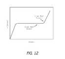
- FIG. 12is a stress-strain curve showing that when the inner wall stretch of single-layer balloon tubing is optimized, the outer wall stretch is sub-optimal and will continue to expand when applied pressure is increased.
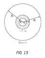
- FIG. 13is a diagram illustrating the inner and outer radii of single-layer balloon tubing in an unexpanded and an expanded state.
- FIG. 14is a graph showing single-layer balloon catheters having diameters of 2 mm, 4 mm, and 6 mm, with wall thickness on the x-axis and the ratio of inner wall stretch to outer wall stretch on the y-axis.
- FIG. 15is a schematic showing the wall profile of a single-layer balloon catheter that is represented in the graph of FIG. 16 .
- FIG. 16is a graph of a single-layer balloon catheter showing the relative stretch ratio as a function of wall slice with wall position on the x-axis and percentage of inner balloon stretch on the y-axis.
- FIG. 17is a graph of a single-layer balloon catheter and a two-layer balloon catheter manufactured from co-extruded tubing.
- FIG. 17shows the inner stretch of wall slices of the two-layer balloon relative to the inner stretch of corresponding wall slices of the single-layer balloon.
- FIG. 18is a graph of a single-layer balloon catheter and two-layer balloon catheter manufactured from tubing in which the inner wall stretch has been optimized for maximum strength.
- FIG. 18shows the inner stretch of wall slices of each layer of the two-layer balloon relative to the inner stretch of corresponding wall slices of the single-layer balloon.
- FIG. 19Ais a perspective view of a balloon catheter having an element shown aligned in a longitudinal direction and in a lateral direction.
- FIG. 19Bis an enlarged perspective view of the longitudinally-aligned element of the balloon catheter as shown in FIG. 19A .
- FIG. 20Ais a diagram of a single layer element with a small thickness bending like a cantilevered beam shown with an applied force and a maximum deflection.
- FIG. 20Bis a diagram of a single layer element with a large thickness bending like a cantilevered beam shown with an applied force and a maximum deflection.
- FIG. 20Cis a diagram of a multi-layer element with three layers each having small thicknesses bending like a cantilevered beam shown with an applied force and a maximum deflection.
- FIG. 20Dis an enlarged side elevational view of the multi-layer element shown in FIG. 20C .
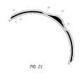
- FIG. 21is a cross-sectional view of a portion of a multi-layer balloon having a discontinuous lubricating layer.
- FIG. 22Ais a side elevational view of an inner balloon used in a method for nesting balloons to form a multi-layer balloon.
- FIG. 22Bis a side elevational view of the inner balloon after heating and stretching of the method for nesting multi-layer balloons of FIG. 22A .
- FIG. 22Cis a side elevational view of the inner balloon after fluting of the method for nesting multi-layer balloons of FIG. 22A .
- FIG. 22Dis a side elevational view of the heated, stretched, and fluted inner balloon and an outer balloon used in the method for nesting multi-layer balloons of FIG. 22A .
- FIG. 22Eis a side elevational view of a multi-layer balloon where lubrication is being applied between the inner balloon and the outer balloon of the method for nesting multi-layer balloons of FIG. 22D .
- FIG. 22Fis a side elevational view of the multi-layer balloon after heating, stretching, and inflating so that the inner balloon and the outer balloon have the same, or a substantially similar, degree of molecular alignment of the method for nesting multi-layer balloons of FIG. 22D .
- FIG. 22Gis a side elevational view of the multi-layer balloon after fluting of the method for nesting multi-layer balloons of FIG. 22D .
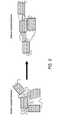
- FIG. 23Ais a side elevational view of a three layer balloon and a two layer balloon used in a method for co-extruding balloons to form a multi-layer balloon.
- FIG. 23Bis a side elevational view of the three layer balloon after heating and stretching so as to the decrease the diameter of the three layer balloon prior to insertion into the two layer balloon of the method for co-extruding multi-layer balloons of FIG. 23A .
- FIG. 23Cis a side elevational view of the three layer balloon having a decreased diameter being inserted into the two layer balloon having its original diameter of the method for co-extruding multi-layer balloons of FIG. 23A .
- FIG. 23Dis a side elevational view of a multi-layer balloon having five layers after heating, stretching, and inflating so that the three layer balloon component and the two layer balloon component have the same, or a substantially similar, degree of molecular alignment of the method for co-extruding multi-layer balloons of FIG. 23A .
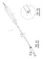
- FIG. 24Ais a side elevational view of a multi-layer balloon formed using the methods disclosed showing a method for welding the necks of the multi-layer balloon in order to securely attach the balloon layers to each other.
- FIG. 24Bis a side elevational view of the multi-layer balloon having its necks welded of FIG. 24A .
- FIG. 25Ais a side elevational view of a single-layer tubular extrusion without a slip layer and a single-layer tubular extrusion of the same size having a slip layer on its inner surface used in a method to form a two-layer high pressure balloon.
- FIG. 25Bis a side elevational view of the single-layer tubing without a slip layer after axial stretching to decrease its diameter prior to insertion into the single-layer extrusion having a slip layer on its inner surface in the method for nesting two-layer balloons of FIG. 25A .
- FIG. 25Cis a side elevational view of the single-layer extrusion having a decreased diameter being inserted into the single-layer extrusion having its original diameter in the method for nesting two-layer balloons of FIG. 25A .
- FIG. 25Dis a side elevational view of a two-layer parison comprising a first balloon layer, a slip layer, and a second balloon layer such that the first balloon layer and the second balloon layer have the same, or a substantially similar, degree of molecular alignment in the method for nesting two-layer balloons of FIG. 25A .
- FIGS. 1A and 1Bshow an exemplary embodiment of a prior art balloon catheter system 1 .
- a balloon 2is attached to the distal end of a catheter shaft 3 and is inflated through an inflation lumen 4 .
- a guide wire lumen 5is provided on the catheter system 1 , which allows for external control of the balloon 2 and the catheter 3 when the system 1 is disposed within a patient. It should be noted that further variations (e.g., rapid exchange, concentric lumen, etc.) are possible for this structure.
- FIG. 2illustrates a perspective view of an embodiment of a prior art catheter balloon 2 in an unwrapped and deflated configuration.
- the balloon 2is folded into a plurality of flutes 6 , typically ranging from three to eight flutes.
- the plurality of flutes 6are formed in a direction substantially parallel to a longitudinal direction of the balloon 7 .
- the plurality of flutes 6are folded with a slight curvature in order to facilitate subsequently wrapping the fluted balloon 2 around the catheter shaft 3 (as shown in FIG. 1A ).
- the balloon 2attaches to the catheter shaft 3 both at a proximal neck of the balloon 50 and at a distal neck of the balloon 51 .
- the balloon 2also includes a body portion 52 , which can be inflated and deflated when the balloon 2 is disposed within the body of a patient during a particular medical procedure.
- FIG. 3Ashows a cross-section of an embodiment of a prior art fluted balloon 2 on a catheter shaft 3 .
- the fluted balloon 2has a plurality of flutes 6 .
- the plurality of flutes 6comprises six flutes.
- the deflated fluted balloon 2has a relatively small cross-sectional area, but can have a relatively wide diameter because the thin flutes 6 stretch radially outward from the catheter shaft 3 .
- the balloon 2can expand to have a much larger diameter and cross-sectional area 8 , as shown in the circular phantom lines in FIG. 3A .
- FIG. 3Bshows a cross-section of an embodiment of a prior art fluted balloon 2 after it has been wrapped.
- the plurality of flutes 6are folded down and about the catheter shaft 3 such that they are in close contact with each other and the catheter shaft 3 .
- the deflated balloon's diameter and cross-sectional area 9(sometimes referred to as the crossing profile) is much smaller than the inflated balloon's diameter and cross-sectional area 8 (as seen in the circular phantom lines in FIG. 3B ). Having a balloon 2 with a small diameter and cross-sectional area 9 allows the catheter 2 to be guided through smaller passageways within a patient's body.
- Inflating the balloon 2 to have a larger diameter and cross-sectional area 8advantageously allows for the placement of a larger stent, occlusion of a larger passageway, and generally greater versatility once the catheter 2 has reached a particular treatment site within a patient's body.
- FIGS. 3C through 3Egenerally illustrate enlarged views of several configurations of balloon folding patterns.
- FIG. 3Cillustrates an enlarged side elevational view of a cross-section of a prior art fluted balloon 2 c after wrapping.
- the reduction in size of the wrapped balloon 2 c about the catheter shaft 3is limited by the balloon's bend radius 10 c .
- a balloon's bend radiusincreases with the thickness and toughness of the balloon, as can be seen by comparing FIG. 3C with FIGS. 3D and 3E .
- FIG. 3Dshows a balloon 2 d that is thicker than the balloon 2 c shown in FIG. 3C .
- FIG. 3Dshows a balloon 2 d that is thicker than the balloon 2 c shown in FIG. 3C .
- the bend radius 10 d for the thicker balloon 2 dis larger than the bend radius of the balloon 2 c in FIG. 3C .
- FIG. 3Eshows a balloon 2 e having the same thickness as the balloon 2 c of FIG. 3C , but being composed of a tougher material than that of the balloon in FIG. 3C .
- the bend radius 10 e for the tougher balloon 2 eis also larger than the bend radius of the balloon 2 c in FIG. 3C . Accordingly, both a thicker balloon 2 d and a tougher balloon 2 e typically cannot be folded into as small a cross-section as the balloon 2 c of FIG. 3C .
- the bend radius of a balloonis important because bending a balloon beyond its bend radius can cause deformities which will lower the balloon's resistance to bursting when inflated.
- FIG. 3Fshows a balloon 2 f wrapped about a catheter shaft 3 .
- the balloon 2 fhas a negligible bend radius and can, therefore, be tightly wrapped about the catheter shaft 3 without any protrusions developing on the outer surface of the folded and wrapped balloon 2 f .
- this configurationpermits the diameter and the cross-section of the balloon 2 f to be minimized prior to, and during, insertion of the balloon catheter system into a patient's body.
- this configurationminimizes failure of the balloon 2 f during a medical application due to a deformity developing on the balloon's outer surface.
- FIGS. 4 through 6generally show deformities that can develop on a balloon's outer surface.
- a wrapped balloon 2is folded and compressed beyond its bend radius 10 creating a crack 11 in the outer surface of the wrapped balloon 2 near the site of a fold.
- Such crackingis more likely for less compliant materials, which also generally have higher burst strengths.
- burst strengththere is a general trade off between burst strength and flexibility.
- FIG. 5shows another deformity that occurs in balloons.
- a medical devicesuch as a stent
- itcan create a scratch 12 .
- the scratch 12generally extends in the longitudinal direction of the balloon 2 . Again, the likelihood of scratching can be minimized by using a more compliant material, which also has a lower burst strength.
- stresswill concentrate near the scratch 12 when the balloon 2 is inflated, causing the scratch 12 to expand and ultimately causing failure of the balloon 2 (e.g., by bursting).
- FIG. 6illustrates yet another type of deformity.
- a balloonWhen a balloon is formed, there may be regions of low molecular density or imperfections in the molecular lattice. As a result, a small hole 13 can form upon stretching the balloon 2 . The hole 13 can grow as the balloon 2 is stretched further, often resembling a “cat-eye.” Stress concentrates near the edges of the cat-eye deformity 13 . Since the balloon 2 is stretched during inflation, this can also lead to failure of the balloon 2 (e.g., by bursting).
- FIGS. 7A and 8Ashow an enlarged cross-section of an embodiment of a multi-layer balloon 2 having a first layer 20 , a second layer 22 , and a third layer 24 .
- the multi-layer balloon 2comprises a balloon having three structural layers
- the first layer 20comprises a top layer of the multi-layer balloon
- the second layer 22comprises a middle layer of the multi-layer balloon
- the third layer 24comprises a bottom layer of the multi-layer balloon.
- the multi-layer balloon 2is shown in the wrapped position, similar to position illustrated in FIG. 3C .
- the first layer 20 of the multi-layer balloonhas a thickness that is approximately one-third the thickness of the single-layer balloon shown in FIG. 3C .
- the second layer 22 and the third layer 24also each have a thickness that is approximately one-third the thickness of the single-layer balloon shown in FIG. 3C . Because each layer 20 , 22 , 24 is thinner than the single-layer balloon of FIG. 3C , the bend radius 10 is smaller for an equal cumulative thickness 3 t . Because the cumulative thickness of the multi-layer balloon 2 of FIG. 7A is substantially the same as the thickness of the single-layer balloon of FIG. 3C , the burst pressure P will also be the substantially the same as long as adjacent balloon layers of the multi-layer balloon can slide relative to each other.
- a balloon 2 with a single layerhas a total thickness 3 t that is equivalent the thickness of the multi-layer balloon 2 shown in FIGS. 7A and 8A .
- the thicker balloon 2has a larger bend radius 10 , and thus cannot be folded as closely to the catheter shaft 3 . If a scratch develops on the first layer 20 of the multi-layer balloon during the crimping and wrapping process, the first layer 20 could burst while, at the same time, the other balloon layers 22 , 24 retain their structural integrity. More generally, a single balloon layer 20 , 22 , 24 might fail as a result of a deformity, such as those shown in FIGS.
- the multi-layer designprovides redundancy that could be valuable in certain medical procedures. Furthermore, because the multi-layer design is more flexible, as discussed below, deformities as shown in FIG. 4 are less likely to occur. Meanwhile, the burst pressure P for a multi-layer balloon is substantially the same as that for an equivalent thickness single layer balloon, as can be seen by comparing FIG. 8A with FIG. 8B . It will be apparent that similar effects can be achieved by varying the material in each balloon layer, varying the number of balloon layers, and varying other aspects of this embodiment.
- the first layer 20 of the multi-layer balloonis made of a soft material that is preferably scratch and puncture resistant.
- a devicesuch as a stent is applied to the catheter system, it is typically crimped onto the balloon 2 .
- the applied crimping forceshould be such as to provide a sufficiently strong attachment force, yet it should also not scratch, pierce, or otherwise damage the balloon wall.
- a softer first layer 20which can comprise an outer layer of the multi-layer balloon), the risk of failure due to scratching can be decreased.
- the second layer 22 and the third layer 24(which can comprise inner layers of the multi-layer balloon) can be made of a tougher material that is less scratch resistant, but able to withstand higher applied pressures. These layers 22 , 24 can be protected from scratching by the soft outer layer 20 , but still can provide additional strength to the multi-layer balloon. It should be noted that the above-described effects need not always be achieved simultaneously, and they are not necessarily sensitive to the number of layers, composition of other layers, form of device carried by the catheter, or other aspects of this embodiment.
- each layer 20 , 22 , 24may be equally sized and shaped in the body portion 52 , in order to optimize the burst characteristics of the balloon in accordance with the present invention.
- each layeris stretched, causing the thickness to shrink. This causes the third balloon layer 24 to stretch approximately as far as the first balloon layer 20 . If the third balloon layer 24 begins with a smaller diameter than that of the first layer 20 , then the third layer 24 must stretch an additional amount to match the size of the first balloon layer 20 . This can cause the inner balloon layers 22 , 24 to burst before the outer balloon layer 20 , which can limit the multi-layer balloon's maximum inflation to a level that inflates the larger outer balloon layer 20 below its optimal inflation level.
- each balloon layerhave a substantially similar burst pressure, ensuring that they burst substantially simultaneously and reducing the possibility of sub-optimal inflation of any layer 20 , 22 , 24 of the multi-layer balloon.
- balloons of different materialmay require different sizes and shapes to achieve this effect.
- the interior balloon layerbursts prior to exterior balloon layers because the multi-layer balloon does not comprise layers having uniform burst strengths. This is primarily a result of not taking into account the confounding effect of radial expansion on achieving optimal radial stretch during the balloon blow molding process.
- an objective of blow molding in balloon formationis to stretch the polymer material in order to achieve maximum strength and semi-compliance. This is done by aligning the molecular chains as shown in FIG. 9 . During the stretching process, the material will grow until the polymer chains are aligned. Once the polymer chains are aligned, the material resists further growth and provides maximum strength. This is shown on the idealized stress-strain curve in FIG. 10 . In response to the strain caused by stretching, the material exhibits relatively even stress. Once the polymer chains are aligned, the material resists further growth as shown by an increase in stress. In the ideal cases, all polymer chains will be uniformly stretched. Various polymer materials will have different ideal stretch ratios in order to achieve uniform molecular alignment.
- Optimum stretch for a multi-layer, high-pressure, balloonis dependent upon a number of variables. For a given material, there is a calculated optimum stretch that provides optimum strength of the multi-layer balloon. The calculated optimum stretch is dependent upon, for example, the diameter of the balloon and the thickness of the layers which comprise the multi-layer, high-pressure, balloon. Practically, it is very difficult to stretch a balloon to its exact optimum stretch. Thus, for most applications, stretching a material to within 15% of its optimum stretch, and preferably to within less than 10%, will provide optimum balloon strength.
- the polymer materialis stretched both radially and longitudinally in order to achieve biaxial orientation of the polymer chains.
- radial stressis twice that of longitudinal stress.
- optimizing the radial stretchis more important to burst resistance than longitudinal stretch.
- radial stretchconfounds the goal to achieve a uniform stretch of the polymer material.
- the reason for thisis that balloons are blow molded from tubing having thicker walls.
- the stretch of the inner wall of the initial tubing to that of the balloonwill be greater than that of the respective outer wall stretch.
- a problem encountered in the artis optimizing the radial stretch of the balloon tubing. If the outer wall stretch be optimized, then the inner wall becomes over-stretched. Consequently, the inner wall will develop micro-tears which can lead to premature failure of the balloon tubing. Therefore, a feasible solution to this problem is to optimize the radial stretch based on the inner wall rather than the outer wall.
- the outer wallis under-stretched when optimizing radial stretch based upon the inner wall of the balloon.
- the inner wallachieves optimal alignment of its polymer chains, as shown on the stress-strain curve, the outer wall has not yet reached optimal alignment of its polymer chains, as shown by being further down the stress-strain curve of FIG. 12 . If the inner portion of the balloon wall fails, the outer portion will continue to stretch thus providing no additional strength to the balloon wall.
- the relative under-stretching of the outer wallcan be substantial. This can be shown using a mathematical model relating the radial expansion of a smaller-diameter hollow cylinder with a given wall thickness (the initial extruded tube) to a hollow cylinder with a larger diameter and thinner walls (the blow molded balloon body).
- FIG. 13shows the various radii to be taken into account from a cross section of the tube and balloon.
- S iR i /r i
- S oR o /r o
- S iR i /r o
- Formula Ishows the equation for the mass (M) of a hollow cylinder based on its radius (r), length (L) and density ( ⁇ ).
- Mmass of a hollow cylinder based on its radius (r), length (L) and density ( ⁇ ).
- rradius
- Llength
- ⁇density
- ⁇density
- S o and S ican be calculated and the confounding effect of radial stretch shown.
- r o⁇ square root over (S L ⁇ (2 R o W B ⁇ W B 2 )+( R o ⁇ W B ) 2 /S i 2 ) ⁇ square root over (S L ⁇ (2 R o W B ⁇ W B 2 )+( R o ⁇ W B ) 2 /S i 2 ) ⁇ III.
- FIG. 14shows the ratio of S o /S i as a function of wall thickness for a number of different balloon diameters.
- the relative under-stretching of the outer wallcan be substantial.
- the outer wall for a 2 mm balloon with a wall thickness of 0.001 incheshas been stretched less than 40% relative to the inner wall. Any increase in wall thickness to try to strengthen the wall shows a further decrease in relative stretching.
- the same 2 mm balloon with a 0.002 inch wall thicknessshows a relative wall stretch of less than 30%.
- FIGS. 15 and 16the confounding effect of radial stretch can be shown in more detail by examining the distribution of relative stretch within the wall. This can be done by “mapping” the respective wall slice in the tube to that of the balloon.
- FIG. 15shows such a map in which the inner wall has a position of 0% and the outer wall has a position of 100%.
- the distribution of relative radial stretchcan be shown.
- FIG. 16shows a graph of a representative balloon with the relative stretch ratio as a function of wall slice. As can be seen, the fall off in relative stretch is not proportional and in fact falls off more quickly from the inner wall.
- the problem of inner balloon burstingis particularly common for co-extruded multi-layer balloons because the interior balloon necessarily has a more optimized inner wall stretch compared to that of outer layers. This is shown in detail on FIG. 17 , in which the relative stretch of the wall slices of a dual layer balloon made from co-extruded tubing is shown relative to a single wall balloon having the same overall wall thickness.
- Known methods of creating multi-layer balloonsprimarily focus on co-extruding balloon elements in order to create a multi-layer balloon. Known methods do not typically involve nesting balloons nor has the confounding effect of radial stretch been considered. Even so, in the case of nesting balloons, the interior balloon occasionally is made smaller to facilitate insertion into the exterior balloon, so the problem of varying stretching remains.
- each balloon layeris molded from tubing in which in the inner wall stretch has been optimized for maximum strength.
- FIG. 18shows the relative stretch of wall slices for such a balloon having two layers. As can been seen, the relative amount of optimally stretched material is greater than that afforded by co-extrusion.
- each layeris made such that the inner wall has been stretched for maximum strength, with the stretch ratio specific for that particular material.
- the inner wallshould be stretched to within about 15% of its optimal stretch and, in some applications, preferably to within less than 10% of its optimal stretch.
- the burst pressurewill be higher than that for any individual layer. Once the burst pressure is reached, all layers will fail.
- the compliance characteristics for the layerswill preferably be equivalent.
- FIGS. 19A and 19Billustrate a balloon wall element 14 of a multi-layer balloon catheter 2 .
- This element 14has a thickness t equal to that of the balloon 2 , or balloon layers 20 , 22 , 24 , and a small width b and a length 1 .
- the element 14can be configured either axially or radially. Taking one end of the element 14 as fixed, the element 14 can be viewed as a cantilevered beam for analytical purposes, as described below in FIGS. 20A through 20D .
- FIG. 20Ashows the balloon element 14 as a single layer of thickness t.
- a balloon element 14 with thickness trequires a force F 1 to bend the element 14 a set distance y.
- FIG. 20Bshows the balloon wall element 14 as a single layer of thickness 3 t .
- This thicker element 14requires a force F 2 , which is twenty-seven times larger than F 1 , to bend the element 14 the same distance y as the element 14 in FIG. 20A (that is, because the force required varies as a cube of the element thickness).
- FIG. 20Cshows a multi-layer element 14 comprised of a first element 15 , a second element 16 , and a third element 17 . Each of the elements 15 , 16 , and 17 has an individual thickness t.
- the multi-layer balloon element 14has a cumulative thickness 3 t .
- Each sub-element 15 , 16 , and 17is individually as thick as the balloon element 14 in FIG. 20A , but collectively as thick as the balloon element 14 in FIG. 20B .
- Each individual element in FIG. 20Crequires a force F 1 to bend a single balloon element a given distance y.
- the multi-layer balloon element 14requires a force F 3 to bend the element 14 a given distance y, which is three times as large as the force in FIG. 20A , but only one third as large as the force in FIG. 20B . As shown in FIG.
- each balloon element layer 15 , 16 , and 17preferably slides relative to the other layers a distance ⁇ 1 . If the balloon element layers 15 , 16 , and 17 are not permitted to slide, then the multi-layered balloon 14 will likely be equivalent to the equally thick balloon in FIG. 20B .
- lubricating layers 18 , 19can be added in between structural layer 15 , 16 , and 17 .
- the lubricating layers 18 , 19can be made of any suitable substance, nonexclusively including high density polyethylene, silicon oil, and carbon nanopowder, but in many medical applications should be biocompatible. It should be noted that lubricating layers are not necessary when friction between structural layers is allowable and, in some applications, desirable.
- lubricantshould be distributed so as to substantially cover the entire surface area between adjacent balloon layers.
- the consequences of not having lubricant covering substantially the entire surface areaare demonstrated in FIG. 21 .
- an abnormally loose region 64can form between the gaps 60 , 62 with abnormally stretched regions adjacent the loose region 64 .
- This unequal distribution of stresscan cause a multi-layer balloon to burst prematurely.
- spreading lubricantwill be less of a concern. For example, low pressure applications and balloon regions with low stress may not require uniform spreading of a lubricious layer between adjacent balloon layers. It should be note that similar problems can develop between any two adjacent balloon layers if lubricant is not evenly distributed.
- Embodiments of the multi-layer balloon disclosed hereincan provide a significant performance improvement over current high pressure balloons.
- the disclosed embodimentsallow for balloon catheters to be used in new applications.
- multi-layer balloonscan be used in ultra high pressure applications such as 50 atmospheres or more for up to 10 mm diameter balloons, and for high pressure applications for very large balloons such as 12 atmospheres or more for up to 30 mm diameter balloons.
- the advantages provided by the multi-layer balloons disclosed hereincan be attributed, at least in part, to forming each layer from tubing where the inner wall stretch has been optimized for maximum strength.
- FIGS. 22A through 22Ggenerally depict a method for nesting balloons to form a multi-layer balloon.
- an inner balloon 30is provided having a proximal neck 50 A and a distal neck 51 A.
- the inner balloon 30is then heated and stretched so that the diameter and cross-sectional area of the inner balloon 30 is decreased, while the length of the inner balloon 30 is at least partially increased, as shown in FIG. 22B . Heating and stretching the inner balloon 30 in this manner typically alters the alignment of the polymer molecules comprising the body of the balloon 30 .
- the inner balloon 30is then fluted using known fluting methods so that the balloon 30 comprises a plurality of flutes.
- the inner balloon 30is then wrapped about a catheter shaft.
- the fluted and wrapped inner balloon 30is illustrated in FIG. 22C .
- the balloon 30can be fluted and wrapped, for example, using known fluting and wrapping machines. Embodiments of such machines can be found in U.S. patent application Ser. No. 11/303,546, filed Dec. 16, 2005 and entitled “Balloon Catheter Folding and Wrapping Devices and Methods,” the contents of which are hereby incorporated by reference in their entirety. Other suitable balloon fluting and wrapping devices, however, can also be used.
- the fluted and wrapped inner balloon 30can be inserted into an outer balloon 31 .
- the outer balloon 31preferably has properties that are substantially similar, or in some cases identical, to those properties of the unstretched and unheated inner balloon 30 described with reference to FIG. 22A .
- the balloons 30 , 31are comprised of tube stock that optimizes the inner wall stretch of the balloons 30 , 31 .
- the outer balloon 31has a proximal neck 50 B and a distal neck 51 B.
- the proximal neck 50 B and the distal neck 51 B of the outer balloon 31have larger diameters than the proximal neck 50 A and distal neck 51 A of the inner balloon 30 .
- the inner balloon 30can be inserted into the outer balloon 31 by drawing it through the outer balloon 31 such that the inner balloon 30 is substantially contained within the outer balloon 31 .
- Other suitable methodscan also be used to insert the inner balloon 30 into the outer balloon 31 .
- the inner balloon 30 and the outer balloon 31are blow-molded on the same mold (but preferably at separate times) so that the balloons 30 , 31 have a substantially similar shape and size along a body portion of the balloons 30 , 31 .
- the balloons 30 , 31preferably have proximal and distal necks having different sizes, as illustrated in FIGS. 22A and 22D . That is, the proximal and distal necks 50 A, 51 A of the inner balloon 30 have a smaller diameter than the proximal and distal necks 50 B, 51 B of the outer balloon 31 .
- lubrication 32can be added to a space disposed between the inner balloon 30 and the outer balloon 31 .
- the lubrication 32comprises silicon oil. It should be noted that lubrication 32 can be added either before the insertion step shown in FIG. 22D , during the insertion step shown in FIG. 22D , or after the insertion step shown in FIG. 22D . In the illustrated balloon nesting method, as shown in FIG. 22E , lubrication 32 is added after the insertion step in FIG. 22D .
- the nested balloons 30 , 31are next heated, stretched, and inflated to bring the respective body portions of the inner balloon 30 and the outer balloon 31 into the same, or a substantially similar, molecular alignment.
- Embodiments of devices capable of inflating and heating a ballooncan be found in U.S. patent application Ser. No. 11/303,545, filed Dec. 16, 2005 and entitled “Measurement Apparatus and Methods for Balloon Catheters,” the contents of which are hereby incorporated by reference in its entirety.
- the embodiments presentedcan be modified to stretch the balloon as well, and also can be used to verify that the balloons have been stretched to an optimal size and shape.
- Other embodimentscan be used to heat, stretch, and inflate the multi-layer balloons disclosed herein.
- Inflation of the ballooncan commence when approximately thirty percent of the stretching remains to be completed.
- the balloonsare preferably stretched to four to five times their initial length. This amount of stretching is meant to optimize biaxial molecular alignment, and it will be apparent that a different method will be suitable for different applications.
- a containing apparatus 61can be used to prevent the lubrication 32 from reaching a welding zone 40 .
- a lubricating layer 32can be distributed evenly by mechanical means, if it is not sufficiently distributed during inflation.
- the multi-layer balloon comprising the inner balloon 30 and the outer balloon 31can be fluted and wrapped in preparation for attachment to a catheter shaft.
- the multi-layer balloonis fluted and wrapped in preparation for insertion into another balloon.
- the multi-layer balloonis fluted and wrapped in preparation for having another balloon inserted into a cavity defined by the multi-layer balloon.
- the above-disclosed nesting methodis particularly suitable for ultra high pressure balloons having large neck diameters relative to their body size. Further variations to the nesting method are possible such as, for example, repetition of this process to produce many-layered balloons, use of non-identically sized or shaped balloons, omission of lubricating layers for certain interfaces, and other suitable methods and processes.
- the above-disclosed methodcomprising independent formation of an inner balloon and an outer balloon and then nesting the balloons allows for a variety of balloon sizes and shapes at each layer. Therefore, this method typically allows for ideal balloon parameters at each layer.
- independent formation of balloon layerscould be a slower and more costly process, particularly for balloons with small necks relative to their bodies.
- the body of the balloonis wider than its neck.
- the body of the inner balloonshould still be capable of fitting through the neck of the outer balloon.
- the body of a ballooncan be narrowed by heating, stretching, fluting, and wrapping.
- the neck of a ballooncan possibly be widened by heating and inflating or stretching the balloon radially, but these methods are limited.
- balloonsAs a result, it is often practical to form balloons independently and then nest them to create multi-layer balloons with a balloon body diameter to neck diameter ratio of 4 to 1 or less. For larger diameter-to-neck ratios, co-extrusion of some balloon layers might be preferable.
- co-extrusionIn the co-extrusion method, as discussed in further detail below with reference to FIGS. 23A through 23D , one avoids the difficulty of nesting balloons. However, the process of co-extrusion limits one's control over the size and shape of each balloon layer, potentially causing some of the problems discussed above, as well as others due to the general lost design freedom. In general, co-extrusion is more efficient than nesting in manufacturing larger multi-layer balloons, in the range above approximately 12 mm in diameter.
- FIGS. 23A through 23Dshow one embodiment of forming multi-layer balloons using a co-extrusion method.
- a three layer balloon 26 and a two layer balloon 27are provided.
- the three layer balloon 26preferably has two structural layers 22 , 24 and one lubricating layer 23 .
- the two layer balloon 27preferably has one structural layer 20 and one lubricating layer 21 .
- the three layer balloon 26 and the two layer balloon 27are both co-extruded.
- the structural layerscomprise a polyamide such as Nylon 12.
- the lubricating layerscomprise 0.0001 to 0.00015 inch high-density polyethylene and/or carbon nanopowder filler.
- the three layer balloon 26is then processed to reduce its diameter and cross-sectional area in a manner similar to that disclosed above with respect to FIG. 22B of the nesting method. That is, the three layer balloon 26 can be heated and stretched so that the diameter and cross-sectional area of the three layer balloon 26 is decreased, while the length of the balloon 26 is at least partially increased. Heating and stretching the three layer balloon 26 in this manner typically alters the alignment of the molecules comprising the body of the balloon 26 .
- the three layer co-extruded and stretched balloon 26(having a decreased diameter) can then be inserted into the two layer co-extruded balloon 27 .
- the three layer balloon 26can simply be slid inside the two layer balloon 27 .
- the lubricating layer 21 of the two layer balloon 27(which can be disposed on an inner surface of the two layer balloon 27 ) facilitates relatively easy insertion of the three layer balloon 26 into the two layer balloon 27 because it reduces friction between the balloons when a structural layer 22 of the three layer balloon 26 (which can be disposed on an outer surface of the three layer balloon 26 ) contacts an inner surface of the two layer balloon 27 .
- the newly-formed five layer multi-layer balloon 25can be heated, stretched, and inflated such that the inner balloon 26 alters its molecular orientation to an orientation that the inner balloon 26 had prior to the heating and stretching step of FIG. 23B (i.e., its original molecular orientation).
- the molecular orientation of the inner balloon 26becomes substantially similar to, or the same as, the molecular orientation of the outer balloon 27 because these balloons had substantially similar, or the same, molecular orientations after co-extrusion (the step of FIG. 23A ) and before drawing down the inner balloon 26 (the step of FIG. 23B ).
- this co-extrusion methodis possible such as, for example, repeating the method steps to create additional balloon layers, using additional co-extruded balloon layers, combining co-extrusion with balloon nesting, using alternative methods to achieve molecular alignment among the balloon layers, and other suitable variations.
- the structural layers of the balloonare typically welded together.
- the lubricating layerspreferably are kept away from a welding zone 40 of the multi-layer balloon.
- a lubricating layeris not co-extruded, it can be injected relatively far from the welding zone and then mechanically dispersed, as shown and described above with respect to FIG. 22E .
- FIGS. 24A and 24Ban analogous process is shown for a co-extruded lubricating layer 42 (as opposed to applying a lubricating layer in a nesting method for creating multi-layer balloons).
- extrusion of the lubricating layer 42is periodically halted to make a lubricating layer-free welding zone 40 .
- thisis accomplished with a diverter valve.
- Use of the diverter valvecan be adjusted to create a balloon parison of appropriate length.
- the structural layers 41 , 43 of the multi-layer co-extruded ballooncan then be welded together in welding zone 40 .
- Other suitable variationscan also be used to separate the lubricating layers from the welding zones.
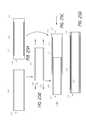
- FIGS. 25A through 25Dshow an embodiment of a method for forming two-layer balloons with each layer made from tubing that optimizes inner wall stretch for maximized balloon strength.
- a single-layer extrusion or tube stock 100 and a single-layer extrusion having a slip layer 110are provided.
- the single-layer extrusion 100preferably has a single, structural side wall 102 .
- the single layer tube stock having a slip layer 110preferably has a single, structural side wall 112 and a slip layer 114 disposed on the inner surface of the side wall 112 .
- the tube stock with a slip layer 110has a bonding zone 116 at each end of the tube stock 110 .
- the bonding zone 116defines an area of the tube stock 110 between the longitudinal ends of the side wall 112 and the ends of the slip layer 114 .
- the bonding zone 116provides an area free from lubrication, which allows the tube stock without a slip layer 100 to be bonded with the tube stock with a slip layer 110 .
- the single-layer tube stock 100 and the single-layer tube stock having a slip layer 110are preferably formed from tubing that optimizes the inner wall stretch thus providing optimum balloon strength.
- the extrusions 100 , 110may be formed from the same material and are preferably formed from the same, or a substantially similar, diameter of tube stock such that the degree of biaxial molecular orientation between the balloons 100 , 110 is substantially similar. If the tube stocks 100 , 110 are composed of the same material, then the diameters of the tube stock should be within about 10% of each other in order to provide balloon layers having a substantially similar degree of biaxial molecular orientation.
- the side walls 102 , 112comprise a polyamide such as Nylon 12.
- the slip layer 114comprises a layer composed of 0.0001 to 0.00015 inch high-density polyethylene and/or carbon nanopowder filler (i.e., “bucky balls” or graphite nanocarbon particles).
- a tubing size of 0.090 inches by 0.056 inchesmay be used.
- the slip layerpreferably will, at a minimum, cover a substantial portion of the main body of the balloon comprising the cylindrical portion of the balloon. However, in some applications, the slip layer may extend beyond the body of the balloon to cover at least a portion of the conical section of the balloon.
- the single-layer extrusion 100is then processed to reduce its diameter and cross-sectional area in a manner similar to that disclosed above with respect to FIGS. 22B and 23B . That is, the single-layer tube stock 100 can be heated and stretched axially so that its diameter and cross-sectional area are at least partially decreased, while the length of the extrusion 100 is at least partially increased. Heating and axial stretching the single-layer extrusion 100 in this manner typically alters the axial alignment of the molecules comprising the body of the extrusion 100 , but induces little or no change to the radial or circumferential alignment.
- the single-layer tube stock 100(having a decreased diameter) can then be inserted into the single-layer tube stock having a slip layer 110 (having its original, unaltered diameter).
- the single-layer extrusion 100can simply be slid concentrically inside the single-layer extrusion having a slip layer 110 .
- the slip layer 114 of the single-layer tube stock 110facilitates relatively easy insertion of the single-layer tube stock 100 into the single layer tube stock having a slip layer 110 because it reduces friction between the balloons when the side wall 102 of the single-layer extrusion 100 contacts an inner surface of the single-layer extrusion having a slip layer 110 .
- the newly-formed two-layer balloon stock or parison 120can be heated, stretched, and inflated such that the inner tube stock 100 alters its molecular orientation to an orientation that the inner tube stock 100 had prior to the heating and stretching step of FIG. 25B (i.e., its original molecular orientation).
- the degree of biaxial molecular orientation of the inner tube stock 100becomes substantially similar to, or the same as, the degree of biaxial molecular orientation of the outer tube stock 110 because these balloons had substantially similar, or the same, molecular orientations at the beginning of the above-described process (the step of FIG. 25A ) and before drawing down the inner tube stock 100 (the step of FIG. 25B ).
- the multi-layer parisondoes not necessarily have lubricating or slip layers.
- the two-layer parison 120 of FIGS. 25A through 25Dcan simply comprise two single-layer extrusions formed from a substantially similar sized tube stock without having a slip layer disposed between the two side walls of the two-layer balloon stock 120 .
- the results of the experimentindicate that a bi-layer balloon with both balloons having maximized radial expansion (i.e., Balloon Design 1) has a 12% greater burst strength and can be subjected to 46% more fatigue cycles than a bi-layer balloon with balloons having different expansion ratios (i.e., Balloon Design 2).
- the resultsalso demonstrate that a bi-layer balloon with both balloons having maximized radial expansion (i.e., Balloon Design 1) has a 14% greater burst strength and can be subjected to 68% more fatigue cycles than a single layer balloon having a thick wall (i.e., Balloon Design 3).
- Fatigue Testing 316085 & 316085-X1 Fatigue Sample 316086(Telescoped 316085-X2 (number of cycles at (Nested tubing w/o (Thick wall fail) Balloons) necking) tubing) Fatigue Pressure (atm) 27 27 27 1 45 41 20 2 71 37 32 3 53 57 25 4 134 64 28 5 150 48 13 6 101 67 24 7 81 38 30 8 82 47 32 9 42 32 32 10 119 41 45 Average Cycle Number 88 47 28 Standard Deviation 37 12 9 % St. Dev. 42.7% 25.1% 30.4% Relative Average 88 (Standard) 49 30 Description of Balloon Failure:
- Balloon Design 1a bi-layer balloon constructed with two balloons with the same expansion ratios (i.e., Balloon Design 1) proves to have superior burst strength and cycle fatigue resistance when compared to a bi-layer balloon with balloons having different expansion ratios (i.e., Balloon Design 2) and to a single layer balloon having a thick wall (i.e., Balloon Design 3).
Landscapes
- Health & Medical Sciences (AREA)
- Life Sciences & Earth Sciences (AREA)
- Heart & Thoracic Surgery (AREA)
- Biomedical Technology (AREA)
- Biophysics (AREA)
- Pulmonology (AREA)
- Engineering & Computer Science (AREA)
- Anesthesiology (AREA)
- Child & Adolescent Psychology (AREA)
- Hematology (AREA)
- Animal Behavior & Ethology (AREA)
- General Health & Medical Sciences (AREA)
- Public Health (AREA)
- Veterinary Medicine (AREA)
- Media Introduction/Drainage Providing Device (AREA)
- Materials For Medical Uses (AREA)
Abstract
Description
M=π(ro2−ri2)Lρ I.
π(ro2−ri2)Ltρt=π(Ro2−Ri2)LBρB II.
ro=√{square root over (SLρ(2RoWB−WB2)+(Ro−WB)2/Si2)}{square root over (SLρ(2RoWB−WB2)+(Ro−WB)2/Si2)} III.
- Create and test multiple variations of plausible, high pressure,
Nylon 12 balloon designs. - Challenge the theory that two nested balloons with maximized expansion ratios is superior to nested balloons with different expansion ratios and thick single walled balloons.
Tools and Equipment: - All burst, compliance, and fatigue testing were completed with the following machines:
- PT-3070 (Pressure Regulation): IA Asset 620
- Laser Measurement System: IA Asset 326
- Temperature Control System: IA Asset 519
- Wall Thickness Measurement Tool:
- Mitutoyo Blade Micrometer: IA Asset 173
- Balloon Blowing Equipment:
- Balloon Forming Machine: 2210H/110V
- Computerized Double End Stretcher: CJS-3X12/110V
- Center Mold: 316061-408
- Distal End Plug: 502155-35
- Proximal End Plug: 502155-34
Part Number and Description of the Balloons Used for Patent Testing:
- 1. 511023 (Balloon Design 1): Multilayer balloon with both balloons having maximized radial expansion.
- a. Inner and outer balloon extrusion part number: 315284-08
- b. Inner and outer balloon extrusion dimensions: 0.090″×0.056″
- 2. 316085-X1 (Balloon Design 2): Multilayer balloon created from nested extrusion.
- a. Inner extrusion part number: 315284-08
- b. Inner extrusion dimensions: 0.090″×0.056″
- c. Outer extrusion part number: 315284-X1
- d. Outer extrusion dimensions: 0.126″×0.092″
- 3. 316085-X2 (Balloon Design 3): Thick, single layer balloon.
- a. Extrusion part number: 315284-X2
- b. Extrusion dimensions: 0.124″×0.056″
- 4. 316085-X3: Multilayer balloon created from nested extrusion. The inner layer extrusion is the same part number as the outer and is drawn down through a hot die so the outer diameter is slightly smaller than the inner diameter of the original tubing size.
- a. Extrusion part number: 315284-08
- b. Extrusion dimensions: 0.090″×0.056″
Description of the Testing Requirements:
- 1. Burst and Compliance Testing: 10 samples per balloon part number.
- While being submerged in 37° C. water, the balloon diameter is measured and recorded while being stepped in 2 ATM increments. The pressure is stepped and recorded until the balloon bursts. Compliance percentage, average burst, and minimum burst strength (“MBS”) are calculated.
- 2. Fatigue Testing: 10 samples per balloon part number.
- Once the different balloons have been burst tested, the least MBS calculated will be used for fatigue testing.
- Each balloon will undergo cycles from 0 to MBS until the balloon bursts. The number of cycles will be recorded and an average will be calculated.
Balloon Development Notes:
- 1. Balloon part numbers 511023, 316085-X1, and 316085-X2 were formed using usual balloon blowing techniques.
- 2. Balloon part number 316085-X3 was not able to be formed.
- To start the development, the necked down inner tubing was solely used to form the 8 mm balloon.
- The logic used was if the inner balloon was not able to be formed, the nested extrusion will also not be able to be formed.
- The extrusion was not able to expand to the walls of the mold due to an inner expansion ratio of approximately 14:1.
Results:
- Create and test multiple variations of plausible, high pressure,
| Balloon Wall Thickness Measurements |
| 316085-X1 | |||
| 316085 & | (Telescoped | 316085-X2 | |
| 316086 | tubing w/o | (Thick | |
| (Standard) | necking) | wall tubing) |
| Double Wall Thickness Measurement (Inches) | ||
| 1 | 0.0062 | 0.0065 | 0.0068 |
| 2 | 0.0062 | 0.0063 | 0.0069 |
| 3 | 0.0064 | 0.0063 | 0.0067 |
| 4 | 0.0063 | 0.0068 | 0.0067 |
| 5 | 0.0064 | 0.0064 | 0.0069 |
| 6 | 0.0062 | 0.0070 | 0.0069 |
| 7 | 0.0063 | 0.0065 | 0.0068 |
| 8 | 0.0064 | 0.0065 | 0.0069 |
| 9 | 0.0064 | 0.0069 | 0.0068 |
| 10 | 0.0064 | 0.0063 | 0.0068 |
| Average Double Wall | 0.0063 | 0.0066 | 0.0068 |
| Thickness (In) | |||
| St. Dev. | 0.0001 | 0.0003 | 0.0001 |
| % St. Dev. | 1.5% | 4.0% | 1.2 |
| Relative Difference | |||
| 0% | 3.6% | 7.9% | |
| 1 | 0.0064 | 0.0066 | 0.0068 |
| 2 | 0.0064 | 0.0065 | 0.0067 |
| 3 | 0.0064 | 0.0065 | 0.0067 |
| 4 | 0.0063 | 0.0063 | 0.0068 |
| 5 | 0.0064 | 0.0068 | 0.0069 |
| 6 | 0.0063 | 0.0066 | 0.0069 |
| 7 | 0.0065 | 0.0067 | 0.0069 |
| 8 | 0.0064 | 0.0067 | 0.0069 |
| 9 | 0.0063 | 0.0068 | 0.0068 |
| 10 | 0.0064 | 0.0067 | 0.0068 |
| Average Double Wall | 0.0064 | 0.0066 | 0.0068 |
| Thickness (In) | |||
| St. Dev. | 0.0001 | 0.0002 | 0.0001 |
| % St. Dev. | 1.0% | 2.3% | 1.2 |
| Relative Difference | |||
| 0% | 3.8% | 6.9% | |
| Burst Testing |
| 316085-X1 | |||
| 316085 & | (Telescoped | 316085-X2 | |
| 316086 | tubing w/o | (Thick wall | |
| Burst Sample Number | (Standard) | necking) | tubing) |
| 1 | 40.04 | 39.46 | 36.09 |
| 2 | 41.38 | 40.03 | 35.94 |
| 3 | 40.27 | 37.85 | 36.08 |
| 4 | 42.19 | 36.22 | 35.94 |
| 5 | 42.21 | 34.03 | 37.37 |
| 6 | 40.03 | 37.89 | 35.94 |
| 7 | 43.76 | 38.12 | 36.14 |
| 8 | 40.03 | 37.4 | 36.76 |
| 9 | 44.34 | 34.04 | 37.85 |
| 10 | 42.75 | 37.78 | 35.94 |
| Average Burst (atm) | 41.70 | 37.28 | 36.41 |
| Relative Burst (atm) | Standard | 35.93 | 33.52 |
| St. Dev. | 1.609 | 2.005 | 0.690 |
| % St. Dev. | 3.9% | 5.4% | 1.9% |
| K-Factor | 5.203 | 5.203 | 5.203 |
| MBS = fatigue pressure | 33.33 | 26.85 | 32.81 |
| Relative MBS | 33.33 (Standard) | 25.87 | 30.22 |
| Minimum (atm) | 40.03 | 34.03 | 35.94 |
| Maximum (atm) | 44.34 | 40.03 | 37.85 |
| Fatigue Testing |
| 316085 & | 316085-X1 | ||
| Fatigue Sample | 316086 | (Telescoped | 316085-X2 |
| (number of cycles at | (Nested | tubing w/o | (Thick wall |
| fail) | Balloons) | necking) | tubing) |
| Fatigue Pressure (atm) | 27 | 27 | 27 |
| 1 | 45 | 41 | 20 |
| 2 | 71 | 37 | 32 |
| 3 | 53 | 57 | 25 |
| 4 | 134 | 64 | 28 |
| 5 | 150 | 48 | 13 |
| 6 | 101 | 67 | 24 |
| 7 | 81 | 38 | 30 |
| 8 | 82 | 47 | 32 |
| 9 | 42 | 32 | 32 |
| 10 | 119 | 41 | 45 |
| Average Cycle Number | 88 | 47 | 28 |
| Standard Deviation | 37 | 12 | 9 |
| % St. Dev. | 42.7% | 25.1% | 30.4% |
| Relative Average | 88 (Standard) | 49 | 30 |
Description of Balloon Failure:
- 511023:
- 12% higher burst and 46% more fatigue cycles than 316085-X1.
- 14% higher burst and 68% more fatigue cycles than 316085-X2.
- The superiority of the nested balloons is due to both balloons having the identical inner and outer expansion ratios.
- The stresses caused by inflation and deflation are the same for each balloon when both have the same inner and outer expansion ratios. When the stresses are the same, the balloons will burst at the same time which ensures maximized burst strength.
- 316085-X1:
- The lower burst strength and fatigue cycles of this balloon are due to the nested tubing having different expansion ratios.
- The outer extrusion has a medium expansion ratio of 2.9:1 while the inner extrusion has 4.4:1.
- Due to the expansion ratio difference, the balloon layers are undergoing different stresses while being inflated and deflated.
- During the burst test, two distinctive “pops” can be heard. The first rupture is the inner balloon and the second rupture is the outer balloon.
- Due to the outer balloons lower expansion ratio, it can withstand more pressure and fatigue cycles than the inner balloon.
- Once the inner balloon bursts, the second balloon immediately ruptures because the pressure is no longer contained by two layers.
- 318085-X2:
- The lower burst strength and fatigue cycles of the thick walled balloon are caused by the same concept of a balloon with nested tubing having different expansion ratios.
- The outer expansion ratio is 2.6:1 while the inner expansion ratio is 5.75:1. The inner diameter has to expand approximately 2.2 times farther than the outer diameter.
- During the burst and fatigue testing, the inner surface of the balloon begins to fracture before the outer surface. This is due to the inner surface reaching its maximum expansion while the outer surface proceeds to grow.
- Once a fracture begins on the inner surface of the balloon, it quickly tears through the entire wall of the balloon causing premature bursts.
- 511023:
Claims (16)
Priority Applications (6)
| Application Number | Priority Date | Filing Date | Title |
|---|---|---|---|
| US11/611,748US7942847B2 (en) | 2005-12-16 | 2006-12-15 | Multi-layer balloons for medical applications and methods for manufacturing the same |
| US13/108,868US8568648B2 (en) | 2005-12-16 | 2011-05-16 | Methods for manufacturing multi-layer balloons for medical applications |
| US14/065,243US9833600B2 (en) | 2005-12-16 | 2013-10-28 | Methods for manufacturing multi-layer balloons for medical applications |
| US15/701,839US10835720B2 (en) | 2005-12-16 | 2017-09-12 | Methods for manufacturing multi-layer balloons for medical applications |
| US17/095,100US11311702B2 (en) | 2005-12-16 | 2020-11-11 | Methods for manufacturing multi-layer balloons for medical applications |
| US17/702,072US20220347442A1 (en) | 2005-12-16 | 2022-03-23 | Methods for manufacturing multi-layer balloons for medical applications |
Applications Claiming Priority (3)
| Application Number | Priority Date | Filing Date | Title |
|---|---|---|---|
| US75101405P | 2005-12-16 | 2005-12-16 | |
| US83152906P | 2006-07-18 | 2006-07-18 | |
| US11/611,748US7942847B2 (en) | 2005-12-16 | 2006-12-15 | Multi-layer balloons for medical applications and methods for manufacturing the same |
Related Child Applications (1)
| Application Number | Title | Priority Date | Filing Date |
|---|---|---|---|
| US13/108,868DivisionUS8568648B2 (en) | 2005-12-16 | 2011-05-16 | Methods for manufacturing multi-layer balloons for medical applications |
Publications (2)
| Publication Number | Publication Date |
|---|---|
| US20070167973A1 US20070167973A1 (en) | 2007-07-19 |
| US7942847B2true US7942847B2 (en) | 2011-05-17 |
Family
ID=38218513
Family Applications (6)
| Application Number | Title | Priority Date | Filing Date |
|---|---|---|---|
| US11/611,748Active2027-10-22US7942847B2 (en) | 2005-12-16 | 2006-12-15 | Multi-layer balloons for medical applications and methods for manufacturing the same |
| US13/108,868ActiveUS8568648B2 (en) | 2005-12-16 | 2011-05-16 | Methods for manufacturing multi-layer balloons for medical applications |
| US14/065,243ActiveUS9833600B2 (en) | 2005-12-16 | 2013-10-28 | Methods for manufacturing multi-layer balloons for medical applications |
| US15/701,839Active2027-10-09US10835720B2 (en) | 2005-12-16 | 2017-09-12 | Methods for manufacturing multi-layer balloons for medical applications |
| US17/095,100ActiveUS11311702B2 (en) | 2005-12-16 | 2020-11-11 | Methods for manufacturing multi-layer balloons for medical applications |
| US17/702,072AbandonedUS20220347442A1 (en) | 2005-12-16 | 2022-03-23 | Methods for manufacturing multi-layer balloons for medical applications |
Family Applications After (5)
| Application Number | Title | Priority Date | Filing Date |
|---|---|---|---|
| US13/108,868ActiveUS8568648B2 (en) | 2005-12-16 | 2011-05-16 | Methods for manufacturing multi-layer balloons for medical applications |
| US14/065,243ActiveUS9833600B2 (en) | 2005-12-16 | 2013-10-28 | Methods for manufacturing multi-layer balloons for medical applications |
| US15/701,839Active2027-10-09US10835720B2 (en) | 2005-12-16 | 2017-09-12 | Methods for manufacturing multi-layer balloons for medical applications |
| US17/095,100ActiveUS11311702B2 (en) | 2005-12-16 | 2020-11-11 | Methods for manufacturing multi-layer balloons for medical applications |
| US17/702,072AbandonedUS20220347442A1 (en) | 2005-12-16 | 2022-03-23 | Methods for manufacturing multi-layer balloons for medical applications |
Country Status (5)
| Country | Link |
|---|---|
| US (6) | US7942847B2 (en) |
| EP (1) | EP1968686B1 (en) |
| JP (1) | JP2009519770A (en) |
| CA (1) | CA2633578A1 (en) |
| WO (1) | WO2007075585A2 (en) |
Cited By (32)
| Publication number | Priority date | Publication date | Assignee | Title |
|---|---|---|---|---|
| US20100042199A1 (en)* | 2008-08-18 | 2010-02-18 | Burton David G | Dilation balloon catheter and methods of use thereof |
| US20100042198A1 (en)* | 2008-08-18 | 2010-02-18 | Burton David G | Single piece double wall dilation balloon catheter |
| US20100249841A1 (en)* | 2006-04-28 | 2010-09-30 | Warsaw Orthopedic, Inc. | Multi-chamber expandable interspinous process spacer |
| US20110022150A1 (en)* | 2005-12-20 | 2011-01-27 | Durcan Jonathan P | Non-compliant multilayered balloon for a catheter |
| US20110152788A1 (en)* | 2009-12-17 | 2011-06-23 | Tyco Healthcare Group Lp | Access assembly with dual anchor and seal capabilities |
| US20110214802A1 (en)* | 2005-12-16 | 2011-09-08 | Interface Associates, Inc. | Methods for manufacturing multi-layer balloons for medical applications |
| US8114136B2 (en) | 2008-03-18 | 2012-02-14 | Warsaw Orthopedic, Inc. | Implants and methods for inter-spinous process dynamic stabilization of a spinal motion segment |
| US8118844B2 (en) | 2006-04-24 | 2012-02-21 | Warsaw Orthopedic, Inc. | Expandable device for insertion between anatomical structures and a procedure utilizing same |
| US8147526B2 (en)* | 2010-02-26 | 2012-04-03 | Kyphon Sarl | Interspinous process spacer diagnostic parallel balloon catheter and methods of use |
| US8252031B2 (en) | 2006-04-28 | 2012-08-28 | Warsaw Orthopedic, Inc. | Molding device for an expandable interspinous process implant |
| US8317831B2 (en) | 2010-01-13 | 2012-11-27 | Kyphon Sarl | Interspinous process spacer diagnostic balloon catheter and methods of use |
| US20130253466A1 (en)* | 2011-06-23 | 2013-09-26 | Carey V. Campbell | Controllable inflation profile balloon cover apparatus and methods |
| US8703260B2 (en) | 2010-09-14 | 2014-04-22 | Abbott Cardiovascular Systems Inc. | Catheter balloon and method for forming same |
| US8708955B2 (en) | 2008-06-02 | 2014-04-29 | Loma Vista Medical, Inc. | Inflatable medical devices |
| US20140194885A1 (en)* | 2013-01-07 | 2014-07-10 | Kyphon Sarl | Catheter with integrated cement delivery balloon |
| US9132259B2 (en) | 2012-11-19 | 2015-09-15 | Abbott Cardiovascular Systems Inc. | Multilayer balloon for a catheter |
| US9174020B2 (en) | 2013-05-08 | 2015-11-03 | Embolx, Inc. | Device and methods for transvascular tumor embolization with integrated flow regulation |
| US9550046B1 (en) | 2016-02-16 | 2017-01-24 | Embolx, Inc. | Balloon catheter and methods of fabrication and use |
| US9592119B2 (en) | 2010-07-13 | 2017-03-14 | C.R. Bard, Inc. | Inflatable medical devices |
| US9844383B2 (en) | 2013-05-08 | 2017-12-19 | Embolx, Inc. | Devices and methods for low pressure tumor embolization |
| US9907684B2 (en) | 2013-05-08 | 2018-03-06 | Aneuclose Llc | Method of radially-asymmetric stent expansion |
| US10166372B2 (en) | 2014-06-06 | 2019-01-01 | Cook Medical Technologies Llc | Angioplasty balloon improved with graphene |
| US10188436B2 (en) | 2010-11-09 | 2019-01-29 | Loma Vista Medical, Inc. | Inflatable medical devices |
| US10188273B2 (en) | 2007-01-30 | 2019-01-29 | Loma Vista Medical, Inc. | Biological navigation device |
| US20190060527A1 (en)* | 2017-08-22 | 2019-02-28 | Cook Medical Technologies Llc | Medical balloons with nanoplatelet composite materials and method of making the same |
| US10286115B2 (en)* | 2008-09-03 | 2019-05-14 | Boston Scientific Scimed, Inc. | Multilayer medical balloon |
| US10350382B1 (en) | 2018-06-08 | 2019-07-16 | Embolx, Inc. | High torque catheter and methods of manufacture |
| US10350395B2 (en) | 2017-06-23 | 2019-07-16 | Cook Medical Technologies Llc | Introducer for lumen support or dilation |
| US11464948B2 (en) | 2016-02-16 | 2022-10-11 | Embolx, Inc. | Balloon catheters and methods of manufacture and use |
| US11623072B2 (en)* | 2014-10-16 | 2023-04-11 | W. L. Gore & Associates, Inc. | Blow molded composite devices and method |
| US12268824B2 (en) | 2018-07-27 | 2025-04-08 | Embolx, Inc. | Shaped catheter tip for tracking over a guidewire through turns in the vasculature |
| US12409298B2 (en) | 2019-08-20 | 2025-09-09 | Embolx, Inc. | Catheters and methods of manufacture and use |
Families Citing this family (37)
| Publication number | Priority date | Publication date | Assignee | Title |
|---|---|---|---|---|
| US6863678B2 (en) | 2001-09-19 | 2005-03-08 | Advanced Cardiovascular Systems, Inc. | Catheter with a multilayered shaft section having a polyimide layer |
| US7727191B2 (en)* | 2005-05-13 | 2010-06-01 | Medtronic Cryocath Lp | Compliant balloon catheter |
| WO2007020087A1 (en)* | 2005-08-19 | 2007-02-22 | Abbott Laboratories Vascular Enterprises Limited | Method of producing a balloon of a balloon catheter |
| US7906066B2 (en) | 2006-06-30 | 2011-03-15 | Abbott Cardiovascular Systems, Inc. | Method of making a balloon catheter shaft having high strength and flexibility |
| US8382738B2 (en) | 2006-06-30 | 2013-02-26 | Abbott Cardiovascular Systems, Inc. | Balloon catheter tapered shaft having high strength and flexibility and method of making same |
| US20140051968A1 (en)* | 2007-01-16 | 2014-02-20 | Radiadyne, Llc | Rectal balloon with sensor cable |
| PL2124831T3 (en) | 2007-03-15 | 2017-03-31 | Ortho-Space Ltd. | Prosthetic devices |
| US8349417B2 (en)* | 2007-11-22 | 2013-01-08 | Stephen Thomas Heffernan | Self-sealing inflatable article |
| US8403885B2 (en) | 2007-12-17 | 2013-03-26 | Abbott Cardiovascular Systems Inc. | Catheter having transitioning shaft segments |
| US7828767B2 (en)* | 2008-05-29 | 2010-11-09 | Boston Scientific Scimed, Inc. | Balloon design and weld design to increase ease of re-wrapping and decrease withdrawal force |
| US8758422B2 (en)* | 2008-06-11 | 2014-06-24 | Boston Scientific Scimed, Inc. | Edge protection via tapered balloon wrap |
| US8444608B2 (en) | 2008-11-26 | 2013-05-21 | Abbott Cardivascular Systems, Inc. | Robust catheter tubing |
| US8070719B2 (en)* | 2008-11-26 | 2011-12-06 | Abbott Cardiovascular Systems, Inc. | Low compliant catheter tubing |
| US8052638B2 (en) | 2008-11-26 | 2011-11-08 | Abbott Cardiovascular Systems, Inc. | Robust multi-layer balloon |
| CN107007921B (en) | 2011-05-26 | 2020-01-21 | 雅培心血管系统有限公司 | Through tip of catheter |
| US9289307B2 (en) | 2011-10-18 | 2016-03-22 | Ortho-Space Ltd. | Prosthetic devices and methods for using same |
| TWI469761B (en)* | 2012-05-23 | 2015-01-21 | Advanced Medical Design Internat Llc | An endo-safe-bag-gasless support system |
| CN103462655A (en)* | 2012-06-06 | 2013-12-25 | 仁齐企业有限公司 | Non-inflatable balloon suspension system |
| US8684963B2 (en) | 2012-07-05 | 2014-04-01 | Abbott Cardiovascular Systems Inc. | Catheter with a dual lumen monolithic shaft |
| US20140018836A1 (en)* | 2012-07-13 | 2014-01-16 | Top-Bound Enterprise Co., Ltd | Endo-Safe-Bag-Gasless support system |
| US20180360586A9 (en) | 2013-03-07 | 2018-12-20 | Merit Medical Systems, Inc. | Embolic filter balloon |
| ES2929182T3 (en)* | 2013-03-12 | 2022-11-25 | Terumo Corp | Balloon and production method thereof |
| US20140277211A1 (en)* | 2013-03-14 | 2014-09-18 | Kyphon Sarl | Device for performing a surgical procedure and method |
| JPWO2014162499A1 (en)* | 2013-04-02 | 2017-02-16 | テルモ株式会社 | Implant assembly |
| WO2015088793A2 (en)* | 2013-12-12 | 2015-06-18 | Mirizzi Michael S | Multiple chamber, expandable therapeutic agent delivery device |
| US20160008589A1 (en)* | 2014-07-10 | 2016-01-14 | Interface Associates, Inc. | Nested balloons for medical applications and methods for manufacturing the same |
| CN106573130B (en)* | 2014-09-04 | 2020-01-24 | 泰尔茂株式会社 | Catheter tube |
| US20160067461A1 (en)* | 2014-09-10 | 2016-03-10 | Daniel Gelbart | Controlled Burst Flexible Medical Balloon with Axially Constant Radial Pressure |
| CA2956128C (en)* | 2014-09-25 | 2023-02-21 | Merit Medical Systems, Inc. | Coated balloons and coated balloon assemblies and related methods of use and manufacture |
| JP6898232B2 (en)* | 2014-10-27 | 2021-07-07 | コンフルエント メディカル テクノロジーズ インコーポレイテッドConfluent Medical Technologies, Inc. | How to make a nested balloon using pressure restraint annealing |
| WO2017046647A1 (en) | 2015-09-18 | 2017-03-23 | Ortho-Space Ltd. | Intramedullary fixated subacromial spacers |
| US10576254B2 (en) | 2016-08-05 | 2020-03-03 | Covidien Lp | Medical balloon having a plurality of structural layers |
| EP3573806A4 (en) | 2017-01-30 | 2019-12-11 | Ortho-Space Ltd. | Processing machine and methods for processing dip-molded articles |
| EP3395379A1 (en) | 2017-04-24 | 2018-10-31 | Biotronik AG | Balloon for a balloon catheter and method for production of such a balloon |
| US10596773B2 (en)* | 2017-05-11 | 2020-03-24 | Medtronic Vascular, Inc. | Multilayer balloons |
| CN118044875A (en)* | 2017-09-07 | 2024-05-17 | 波士顿科学医学有限公司 | Cryoballoon with greater size adjustability at lower ablation pressures |
| CN116211429A (en)* | 2023-03-28 | 2023-06-06 | 深圳市益心达医学新技术有限公司 | A kind of manufacturing method of balloon component, vertebral body balloon catheter and balloon component |
Citations (59)
| Publication number | Priority date | Publication date | Assignee | Title |
|---|---|---|---|---|
| US4327736A (en) | 1979-11-20 | 1982-05-04 | Kanji Inoue | Balloon catheter |
| US4637396A (en) | 1984-10-26 | 1987-01-20 | Cook, Incorporated | Balloon catheter |
| US4651721A (en) | 1985-04-10 | 1987-03-24 | American Medical Systems, Inc. | Penile prosthesis system |
| US4702252A (en) | 1983-10-13 | 1987-10-27 | Smiths Industries Public Limited Company | Catheters |
| JPH02119874A (en) | 1988-10-28 | 1990-05-07 | Kanji Inoue | Balloon catheter |
| US4932956A (en) | 1988-05-10 | 1990-06-12 | American Medical Systems, Inc. | Prostate balloon dilator |
| US4932958A (en) | 1988-05-10 | 1990-06-12 | American Medical Systems, Inc. | Prostate balloon dilator |
| EP0421031A1 (en) | 1989-10-03 | 1991-04-10 | American Medical Systems, Inc. | Prostate balloon dilator |
| US5195969A (en) | 1991-04-26 | 1993-03-23 | Boston Scientific Corporation | Co-extruded medical balloons and catheter using such balloons |
| US5207700A (en) | 1988-08-08 | 1993-05-04 | Scimed Life Systems, Inc. | Polyimide balloon catheter and method of forming a balloon therefor |
| US5270086A (en) | 1989-09-25 | 1993-12-14 | Schneider (Usa) Inc. | Multilayer extrusion of angioplasty balloons |
| US5342305A (en) | 1992-08-13 | 1994-08-30 | Cordis Corporation | Variable distention angioplasty balloon assembly |
| US5344401A (en) | 1991-12-20 | 1994-09-06 | Interventional Technologies Inc. | Catheter balloon formed from a polymeric composite |
| US5358487A (en) | 1993-10-15 | 1994-10-25 | Cordis Corporation | Frangible balloon catheter |
| US5358486A (en) | 1987-01-09 | 1994-10-25 | C. R. Bard, Inc. | Multiple layer high strength balloon for dilatation catheter |
| US5478320A (en) | 1989-11-29 | 1995-12-26 | Cordis Corporation | Puncture resistant balloon catheter and method of manufacturing |
| US5512051A (en)* | 1993-02-16 | 1996-04-30 | Boston Scientific Corporation | Slip-layered catheter balloon |
| US5514092A (en) | 1994-08-08 | 1996-05-07 | Schneider (Usa) Inc. | Drug delivery and dilatation-drug delivery catheters in a rapid exchange configuration |
| US5587125A (en) | 1994-08-15 | 1996-12-24 | Schneider (Usa) Inc. | Non-coextrusion method of making multi-layer angioplasty balloons |
| US5613979A (en) | 1989-11-29 | 1997-03-25 | Cordis Corporation | Puncture resistant balloon catheter |
| US5693014A (en) | 1993-08-23 | 1997-12-02 | Boston Scientific Corporation | Balloon catheter |
| US5746745A (en) | 1993-08-23 | 1998-05-05 | Boston Scientific Corporation | Balloon catheter |
| US5797877A (en) | 1993-10-01 | 1998-08-25 | Boston Scientific Corporation | Medical device balloons containing thermoplastic elastomers |
| US5868776A (en) | 1996-09-03 | 1999-02-09 | Ideas For Medicine, Inc. | Overlay dual balloon catheter and method for use thereof |
| US5879369A (en) | 1995-10-11 | 1999-03-09 | Terumo Kabushiki Kaisha | Catheter balloon and balloon catheter |
| US5908406A (en) | 1996-01-31 | 1999-06-01 | E. I. Du Pont De Nemours And Company | Dilatation catheter balloons with improved puncture resistance |
| US6004289A (en) | 1990-05-15 | 1999-12-21 | Medtronic Ave, Inc. | Multiple layer high strength balloon for dilatation catheter |
| US6024722A (en) | 1994-01-06 | 2000-02-15 | Scimed Life Systems, Inc. | Thermoplastic polyimide balloon catheter construction |
| US6124007A (en) | 1996-03-06 | 2000-09-26 | Scimed Life Systems Inc | Laminate catheter balloons with additive burst strength and methods for preparation of same |
| US6136011A (en) | 1998-07-14 | 2000-10-24 | Advanced Cardiovascular Systems, Inc. | Stent delivery system and method of use |
| US6242063B1 (en) | 1997-09-10 | 2001-06-05 | Scimed Life Systems, Inc. | Balloons made from liquid crystal polymer blends |
| US6293959B1 (en) | 1998-11-16 | 2001-09-25 | Cordis Corporation | Balloon catheter and stent delivery system having enhanced stent retention and method |
| WO2001089619A1 (en) | 2000-05-26 | 2001-11-29 | Wallsten Medical S.A. | Balloon catheter |
| US6358227B1 (en) | 1997-09-10 | 2002-03-19 | Scimed Life Systems, Inc. | Dilatation catheter balloon made from pen based homopolymer or random copolymer |
| US20020165523A1 (en) | 2000-03-02 | 2002-11-07 | Chin Albert C. C. | Multilayer medical device |
| US20020177866A1 (en) | 2001-04-19 | 2002-11-28 | Stuart Weikel | Inflatable device and method for reducing fractures in bone and in treating the spine |
| US6506202B1 (en) | 2000-07-10 | 2003-01-14 | Advanced Cardiovascular Systems, Inc. | Expandable stent dimensional retention system and method |
| US20030093107A1 (en) | 2001-09-28 | 2003-05-15 | Edward Parsonage | Medical devices comprising nanocomposites |
| US20040006359A1 (en) | 2002-07-02 | 2004-01-08 | Laguna Alvaro J. | Balloon catheter and treatment |
| US20040078052A1 (en) | 2002-10-21 | 2004-04-22 | St. Pierre Ernest J. | Multilayer medical device |
| US20040098021A1 (en) | 2002-07-02 | 2004-05-20 | Sentient Engineering & Technology, L.L.C. | Balloon catheter and treatment apparatus |
| US6756094B1 (en) | 2000-02-28 | 2004-06-29 | Scimed Life Systems, Inc. | Balloon structure with PTFE component |
| US20040181252A1 (en) | 1999-11-19 | 2004-09-16 | Boyle Christopher T. | Balloon catheter having metal balloon and method of making same |
| US20050008560A1 (en)* | 2003-05-20 | 2005-01-13 | Futaba Corporation | Ultra-dispersed nanocarbon and method for preparing the same |
| US20050015105A1 (en) | 2003-07-18 | 2005-01-20 | Scimed Life Systems, Inc. | Protective coatings for medical devices |
| US20050015047A1 (en) | 2003-07-18 | 2005-01-20 | Shah Tilak M. | Inflatable dual balloon catheter |
| US6872215B2 (en) | 1994-02-24 | 2005-03-29 | Adiance Medical Systems, Inc. | Focalized stent implantation |
| US20050113856A1 (en) | 2003-10-15 | 2005-05-26 | Epstein Adam S. | Method of joining materials |
| US6902571B2 (en) | 2002-08-29 | 2005-06-07 | Advanced Cardiovascular Systems, Inc. | Compacted catheter balloon and method of incremental compaction |
| US20050137619A1 (en) | 2003-12-19 | 2005-06-23 | Scott Schewe | Molds and related methods and articles |
| US6911017B2 (en) | 2001-09-19 | 2005-06-28 | Advanced Cardiovascular Systems, Inc. | MRI visible catheter balloon |
| US6946173B2 (en) | 2002-03-21 | 2005-09-20 | Advanced Cardiovascular Systems, Inc. | Catheter balloon formed of ePTFE and a diene polymer |
| US20050209629A1 (en) | 2001-04-19 | 2005-09-22 | Kerr Sean H | Resorbable containment device and process for making and using same |
| US20050231721A1 (en) | 2002-06-06 | 2005-10-20 | Masamichi Inenaga | Wafer pre-alignment apparatus and method |
| US20050261721A1 (en) | 2004-05-24 | 2005-11-24 | Radisch Herbert R Jr | Medical device systems |
| US20050266109A1 (en) | 2003-01-27 | 2005-12-01 | Scimed Life Systems, Inc., A Delaware Corporation | Multilayer balloon catheter |
| US6972024B1 (en) | 2001-12-21 | 2005-12-06 | Advanced Cardiovascular Systems, Inc. | Method of treating vulnerable plaque |
| US7025745B2 (en) | 2002-10-07 | 2006-04-11 | Advanced Cardiovascular Systems, Inc. | Method of making a catheter balloon using a tapered mandrel |
| US20060085023A1 (en) | 2004-10-15 | 2006-04-20 | Davies William F Jr | Medical balloon having strengthening rods |
Family Cites Families (186)
| Publication number | Priority date | Publication date | Assignee | Title |
|---|---|---|---|---|
| US1051777A (en) | 1911-07-22 | 1913-01-28 | Albert J St Mars | Tube-swage. |
| US1210895A (en) | 1914-10-15 | 1917-01-02 | Baltimore Tube Company Inc | Apparatus for and method of corrugating metal tubes. |
| US1894800A (en) | 1930-03-27 | 1933-01-17 | American Brass Co | Feed mechanism for swaging machines |
| US2030803A (en) | 1931-08-18 | 1936-02-11 | Robert Temple Inc | Compressing device |
| US2617319A (en) | 1949-02-24 | 1952-11-11 | United States Steel Corp | Apparatus for cold-reducing tubular metal stock |
| US3044326A (en) | 1959-10-16 | 1962-07-17 | Ribback Erich | Apparatus for cold-reducing elongated metallic shock |
| US3273367A (en) | 1964-03-04 | 1966-09-20 | Hallden Machine Company | Rotary swager |
| US3374651A (en) | 1965-10-23 | 1968-03-26 | Barber Colman Co | Machine for forming gears |
| LU57123A1 (en) | 1967-11-09 | 1969-01-27 | ||
| US3668915A (en) | 1969-04-28 | 1972-06-13 | Bernd Ribback | Machine tool for plastic shaping or fashioning |
| AT289513B (en) | 1969-06-27 | 1971-04-26 | Ges Fertigungstechnik & Maschb | Forging machine |
| AT289514B (en) | 1969-07-02 | 1971-04-26 | Ges Fertigungstechnik & Maschb | Additional device for processing tubular workpieces in forging machines |
| US3845650A (en) | 1973-01-19 | 1974-11-05 | B Romanov | Machine for manufacturing a coil of a pipe by bending it |
| GB1526221A (en) | 1975-08-04 | 1978-09-27 | Ccl Systems Ltd | Swaging press |
| AT348094B (en) | 1977-02-17 | 1979-01-25 | Hanecka Lubomir Dipl Ing | BALLOON CATHETER |
| US4418458A (en) | 1978-08-09 | 1983-12-06 | Hunter John J | Apparatus for making pipe coupling joint |
| US4384470A (en) | 1981-04-13 | 1983-05-24 | Joseph Fiore | Method and apparatus for testing blood vessel catheters |
| AT376589B (en) | 1982-02-04 | 1984-12-10 | Karl Sauder | DEVICE FOR COMPRESSING TUBULAR PARTS |
| US4685447A (en) | 1985-03-25 | 1987-08-11 | Pmt Corporation | Tissue expander system |
| US4651738A (en) | 1985-08-02 | 1987-03-24 | Baylor College Of Medicine | Method and device for performing transluminal angioplasty |
| US4781192A (en) | 1986-12-22 | 1988-11-01 | Baylor College Of Medicine | Balloon dilation apparatus |
| US4932658A (en)* | 1987-03-12 | 1990-06-12 | Antonious A J | Golf club head |
| US5499980A (en) | 1988-08-08 | 1996-03-19 | Scimed Life Systems, Inc. | Polyimide balloon catheter and method of making same |
| US4891877A (en) | 1989-03-20 | 1990-01-09 | Dino Talavera | Portable tool for compressing a fitting on a hose |
| JP2545981B2 (en) | 1989-05-09 | 1996-10-23 | 東レ株式会社 | Balloon catheter |
| JPH0312106U (en) | 1989-06-21 | 1991-02-07 | ||
| JP2706998B2 (en)* | 1990-08-03 | 1998-01-28 | 信越化学工業株式会社 | Polyamic acid copolymer and method for producing the same |
| US5142160A (en) | 1990-08-31 | 1992-08-25 | Frank Storbeck | Method and device for determining the volume of an object on a flat background |
| IS1666B (en) | 1991-02-19 | 1997-11-14 | Marel Hf | Method and apparatus for determining the volume, shape and weight of fish or other parts |
| CA2043346A1 (en) | 1991-05-27 | 1992-11-28 | Robina Bernard | Apparatus for measuring inflated balloons |
| US5171299A (en) | 1991-08-02 | 1992-12-15 | Baxter International Inc. | Balloon catheter inflation pressure and diameter display apparatus and method |
| JPH05192408A (en) | 1991-09-06 | 1993-08-03 | C R Bard Inc | Production of expansion balloon |
| EP0569263B1 (en) | 1992-04-06 | 1997-07-02 | Terumo Kabushiki Kaisha | Balloon catheter |
| US5447497A (en) | 1992-08-06 | 1995-09-05 | Scimed Life Systems, Inc | Balloon catheter having nonlinear compliance curve and method of using |
| US5500180A (en) | 1992-09-30 | 1996-03-19 | C. R. Bard, Inc. | Method of making a distensible dilatation balloon using a block copolymer |
| US6896842B1 (en) | 1993-10-01 | 2005-05-24 | Boston Scientific Corporation | Medical device balloons containing thermoplastic elastomers |
| US5445646A (en) | 1993-10-22 | 1995-08-29 | Scimed Lifesystems, Inc. | Single layer hydraulic sheath stent delivery apparatus and method |
| US5350361A (en) | 1993-11-10 | 1994-09-27 | Medtronic, Inc. | Tri-fold balloon for dilatation catheter and related method |
| US5718861A (en) | 1993-12-20 | 1998-02-17 | C. R. Bard, Incorporated | Method of forming intra-aortic balloon catheters |
| JP3548913B2 (en)* | 1993-12-28 | 2004-08-04 | ボストン サイエンティフィック コーポレーション | Slip layered balloon and method for producing the same |
| ES2107901T3 (en) | 1994-01-18 | 1997-12-01 | Gfm Fertigungstechnik | FORGING MACHINE. |
| US5538510A (en) | 1994-01-31 | 1996-07-23 | Cordis Corporation | Catheter having coextruded tubing |
| US5833657A (en) | 1995-05-30 | 1998-11-10 | Ethicon, Inc. | Single-walled balloon catheter with non-linear compliance characteristic |
| US5647848A (en) | 1995-06-07 | 1997-07-15 | Meadox Medicals, Inc. | High strength low compliance composite balloon for balloon catheters |
| US20060271091A1 (en) | 1995-09-18 | 2006-11-30 | Campbell Carey V | Balloon catheter device |
| US5868704A (en) | 1995-09-18 | 1999-02-09 | W. L. Gore & Associates, Inc. | Balloon catheter device |
| US5752934A (en) | 1995-09-18 | 1998-05-19 | W. L. Gore & Associates, Inc. | Balloon catheter device |
| US5807327A (en) | 1995-12-08 | 1998-09-15 | Ethicon, Inc. | Catheter assembly |
| US5681522A (en) | 1996-04-01 | 1997-10-28 | Schneider (Usa) Inc. | Method and apparatus for annealing angioplasty balloons to improve re-wrappability thereof |
| ATE327797T1 (en) | 1996-04-26 | 2006-06-15 | Schneider Europ Gmbh | INTERVENTION CATHETER |
| JP3968444B2 (en) | 1996-08-23 | 2007-08-29 | ボストン サイエンティフィック サイムド,インコーポレイテッド | Stent delivery mechanism with stent fixation device |
| US6123712A (en) | 1996-08-23 | 2000-09-26 | Scimed Life Systems, Inc. | Balloon catheter with stent securement means |
| JP3309743B2 (en) | 1996-11-27 | 2002-07-29 | 富士ゼロックス株式会社 | Shape measuring method and device |
| US5843027A (en) | 1996-12-04 | 1998-12-01 | Cardiovascular Dynamics, Inc. | Balloon sheath |
| US5841541A (en) | 1996-12-31 | 1998-11-24 | Pitney Bowes Inc. | Apparatus and method for dimensional weighing utilizing a rotating sensor |
| US5879282A (en) | 1997-01-21 | 1999-03-09 | Cordis A Johnson And Johnson Company | Catheter having an expandable radioactive source |
| CA2232250C (en) | 1997-05-14 | 2007-06-26 | Navius Corporation | Balloon for a dilation catheter and method for manufacturing a balloon |
| US5810873A (en) | 1997-07-15 | 1998-09-22 | Advanced Cardiovascular Systems, Inc. | Stent crimping tool and method of use |
| DE19738977A1 (en) | 1997-09-05 | 1999-03-18 | Blum Novotest Gmbh | Measuring device for scanning dimensions, in particular diameters |
| WO1999013924A2 (en) | 1997-09-17 | 1999-03-25 | Advanced Cardiovascular Systems, Inc. | Polyether block amide catheter balloons |
| DE59703151D1 (en) | 1997-11-13 | 2001-04-19 | Gfm Beteiligungs & Man Gmbh | Rotary kneading machine |
| US6296633B1 (en) | 1998-01-09 | 2001-10-02 | Schneider (Usa) Inc. | Medical device tubing assembly and method of making the same |
| DE69914882T2 (en) | 1998-03-04 | 2004-12-16 | Boston Scientific Ltd., St. Michael | COMPOSITION AND METHOD FOR PRODUCING PBT CATHETER BALLOONS |
| US6024752A (en) | 1998-05-11 | 2000-02-15 | Scimed Life Systems, Inc. | Soft flexible tipped balloon |
| US6036697A (en) | 1998-07-09 | 2000-03-14 | Scimed Life Systems, Inc. | Balloon catheter with balloon inflation at distal end of balloon |
| AT407618B (en) | 1998-12-07 | 2001-05-25 | Gfm Beteiligungs & Man Gmbh | ROUND KNOWING MACHINE |
| US6395208B1 (en) | 1999-01-25 | 2002-05-28 | Atrium Medical Corporation | Method of making an expandable fluoropolymer device |
| US6955661B1 (en) | 1999-01-25 | 2005-10-18 | Atrium Medical Corporation | Expandable fluoropolymer device for delivery of therapeutic agents and method of making |
| US7637886B2 (en) | 1999-01-25 | 2009-12-29 | Atrium Medical Corporation | Expandable fluoropolymer device and method of making |
| US6283959B1 (en)* | 1999-08-23 | 2001-09-04 | Cyrocath Technologies, Inc. | Endovascular cryotreatment catheter |
| DE29915724U1 (en) | 1999-09-07 | 1999-12-23 | Angiomed GmbH & Co. Medizintechnik KG, 76227 Karlsruhe | Stent delivery system |
| US6695809B1 (en) | 1999-09-13 | 2004-02-24 | Advanced Cardiovascular Systems, Inc. | Catheter balloon with a discontinuous elastomeric outer layer |
| JP3823635B2 (en) | 1999-09-21 | 2006-09-20 | 日本精工株式会社 | Method and apparatus for evaluating surface shape of ball bearing ball |
| US6360577B2 (en) | 1999-09-22 | 2002-03-26 | Scimed Life Systems, Inc. | Apparatus for contracting, or crimping stents |
| US6481262B2 (en) | 1999-12-30 | 2002-11-19 | Advanced Cardiovascular Systems, Inc. | Stent crimping tool |
| US6461326B1 (en) | 2000-10-26 | 2002-10-08 | Scimed Life Systems, Inc. | Fluorescent dyed adhesive for bonding various components in a medical device |
| US7229518B1 (en) | 2000-11-02 | 2007-06-12 | Nike, Inc. | Process for improving interfacial adhesion in a laminate |
| US6547768B2 (en) | 2000-12-14 | 2003-04-15 | Cordis Corporation | Medical devices with reduced friction polyamides, and method |
| US6869653B2 (en)* | 2001-01-08 | 2005-03-22 | Baxter International Inc. | Port tube closure assembly |
| JP3647378B2 (en) | 2001-03-02 | 2005-05-11 | キヤノン株式会社 | Shape measuring apparatus and measuring method using multiprobe |
| WO2002076700A1 (en) | 2001-03-26 | 2002-10-03 | Machine Solutions, Inc. | Balloon folding technology |
| DE10125998A1 (en) | 2001-05-18 | 2002-11-21 | Nils Kucher | Catheter for treating massive lung embolism incorporates main catheter body, impeller, rinsing and suction tubes, and protective sleeve |
| US20030009151A1 (en)* | 2001-07-03 | 2003-01-09 | Scimed Life Systems, Inc. | Biaxially oriented multilayer polymer tube for medical devices |
| CA2463691C (en) | 2001-10-19 | 2008-06-17 | Kuraray Co., Ltd. | Layered product and medical supply comprising the layered product |
| US7914486B2 (en) | 2001-12-20 | 2011-03-29 | Boston Scientific Scimed, Inc. | Catheter having an improved balloon-to-catheter bond |
| US6923787B2 (en) | 2001-12-20 | 2005-08-02 | Scimed Life Systems, Inc. | Catheter having an improved balloon-to-catheter bond |
| US7037562B2 (en) | 2002-01-14 | 2006-05-02 | Vascon Llc | Angioplasty super balloon fabrication with composite materials |
| US7985234B2 (en) | 2002-02-27 | 2011-07-26 | Boston Scientific Scimed, Inc. | Medical device |
| US7314461B2 (en) | 2002-04-23 | 2008-01-01 | Wilson-Cook Medical, Inc. | Precalibrated inflation device for balloon catheter |
| DK1521603T3 (en) | 2002-07-12 | 2011-04-18 | Cook Inc | Coated medical device |
| US7449010B1 (en) | 2002-07-15 | 2008-11-11 | Motoya Hayase | Material removal catheter and method |
| JP4351832B2 (en) | 2002-08-05 | 2009-10-28 | テルモ株式会社 | Balloon catheter |
| US6931899B2 (en) | 2002-08-16 | 2005-08-23 | Machine Solutions, Inc. | Swaging technology |
| US7323233B2 (en) | 2002-09-26 | 2008-01-29 | Scimed Life Systems, Inc. | Sheath materials and processes |
| US7105013B2 (en) | 2002-09-30 | 2006-09-12 | Advanced Cardiovascular Systems, Inc. | Protective sleeve assembly for a balloon catheter |
| AU2003300202A1 (en) | 2003-01-02 | 2004-07-29 | Novoste Corporation | Drug delivery balloon catheter |
| US7010953B2 (en) | 2003-02-04 | 2006-03-14 | Interface Associates, Inc. | Swaging machine and method of use |
| US6993953B2 (en) | 2003-02-04 | 2006-02-07 | Interface Associates, Inc. | Swaging die and method of use |
| US7314480B2 (en) | 2003-02-27 | 2008-01-01 | Boston Scientific Scimed, Inc. | Rotating balloon expandable sheath bifurcation delivery |
| US7367989B2 (en) | 2003-02-27 | 2008-05-06 | Scimed Life Systems, Inc. | Rotating balloon expandable sheath bifurcation delivery |
| JP4617070B2 (en) | 2003-07-29 | 2011-01-19 | テルモ株式会社 | Catheter with expansion body |
| US9180620B2 (en) | 2003-08-21 | 2015-11-10 | Boston Scientific Scimed, Inc. | Medical balloons |
| US20050075711A1 (en) | 2003-10-03 | 2005-04-07 | Neary Anthony J. | Balloon catheter with selectable diameter and expandable length |
| ATE475448T1 (en) | 2003-10-03 | 2010-08-15 | Medtronic Inc | EXPANDABLE GUIDE LOCK AND DEVICE |
| FR2863785B1 (en) | 2003-12-11 | 2006-04-28 | Airbus France | DEVICE FOR CRIMPING A CONTACT ON A CABLE |
| US20050177104A1 (en) | 2004-01-22 | 2005-08-11 | Rochester Medical Corporation | Cuff resistant foley catheter |
| US7713233B2 (en) | 2004-04-12 | 2010-05-11 | Boston Scientific Scimed, Inc. | Balloons having a crosslinkable layer |
| US7659000B2 (en) | 2004-04-12 | 2010-02-09 | Boston Scientific Scimed, Inc. | Adhesion technique for incompatible polymers using modified polymer tie layers |
| WO2005107641A2 (en) | 2004-05-03 | 2005-11-17 | Fulfillium, Inc. | Method and system for gastric volume control |
| US8353867B2 (en) | 2004-05-04 | 2013-01-15 | Boston Scientific Scimed, Inc. | Medical devices |
| US7126694B1 (en) | 2004-05-14 | 2006-10-24 | Artium Technologies, Inc. | Compact apparatus providing multi-dimensional characterization of spherical objects using coherent light |
| US7758572B2 (en) | 2004-05-20 | 2010-07-20 | Boston Scientific Scimed, Inc. | Medical devices and methods including cooling balloons having nanotubes |
| US7758892B1 (en) | 2004-05-20 | 2010-07-20 | Boston Scientific Scimed, Inc. | Medical devices having multiple layers |
| US20050281721A1 (en)* | 2004-06-21 | 2005-12-22 | Maxwell Hsu | Standby current generator for an ozonizer |
| US7389670B1 (en) | 2004-07-26 | 2008-06-24 | Abbott Laboratories | Stent crimping system |
| US7641688B2 (en) | 2004-09-16 | 2010-01-05 | Evera Medical, Inc. | Tissue augmentation device |
| US20060079922A1 (en) | 2004-10-12 | 2006-04-13 | Brian Creston | Balloon anchored surgical apparatus, its use and manufacture |
| US7309324B2 (en) | 2004-10-15 | 2007-12-18 | Futuremed Interventional, Inc. | Non-compliant medical balloon having an integral woven fabric layer |
| US7682335B2 (en) | 2004-10-15 | 2010-03-23 | Futurematrix Interventional, Inc. | Non-compliant medical balloon having an integral non-woven fabric layer |
| US20090089079A1 (en) | 2004-11-09 | 2009-04-02 | The Brigham And Women's Hospital, Inc. | System and method for determining whether to issue an alert to consider prophylaxis for a risk condition |
| US7578165B1 (en) | 2004-12-17 | 2009-08-25 | Interface Associates, Inc. | Measurement apparatus and methods for balloon catheters |
| US7762804B1 (en) | 2004-12-17 | 2010-07-27 | Interface Associates, Inc. | Balloon catheter folding and wrapping devices and methods |
| JP4535868B2 (en) | 2004-12-28 | 2010-09-01 | テルモ株式会社 | catheter |
| US20060165926A1 (en) | 2005-01-27 | 2006-07-27 | Jan Weber | Medical devices including nanocomposites |
| US8048028B2 (en) | 2005-02-17 | 2011-11-01 | Boston Scientific Scimed, Inc. | Reinforced medical balloon |
| US20060182873A1 (en) | 2005-02-17 | 2006-08-17 | Klisch Leo M | Medical devices |
| US20080228138A1 (en) | 2005-03-31 | 2008-09-18 | Van Sloten Leonard A | Catheter with balloon having visual marker |
| EP2823907A3 (en) | 2005-04-15 | 2015-07-29 | Machine Solutions, Inc. | Swaging technology |
| US7290352B2 (en) | 2005-05-16 | 2007-11-06 | Tenneco Automotive Operating Company Inc. | measurement device for a support land for a valve disc |
| US7628800B2 (en) | 2005-06-03 | 2009-12-08 | Warsaw Orthopedic, Inc. | Formed in place corpectomy device |
| US8034066B2 (en) | 2005-09-15 | 2011-10-11 | Boston Scientific Scimed, Inc. | Multi-layer medical balloons |
| EP1948286B1 (en) | 2005-11-14 | 2016-12-07 | SIS Medical AG | Balloon catheter |
| US20070142772A1 (en) | 2005-12-16 | 2007-06-21 | Medtronic Vascular, Inc. | Dual-Layer Medical Balloon |
| JP2009519770A (en) | 2005-12-16 | 2009-05-21 | インターフェイス・アソシエイツ・インコーポレーテッド | Medical multilayer balloon and method for producing the same |
| US7828766B2 (en) | 2005-12-20 | 2010-11-09 | Advanced Cardiovascular Systems, Inc. | Non-compliant multilayered balloon for a catheter |
| US8388599B2 (en) | 2006-05-05 | 2013-03-05 | Abbott Laboratories | Method with balloon catheter having first and second inflatable elements |
| EP2029215B1 (en) | 2006-06-07 | 2019-03-13 | SIS Medical AG | Monorail catheter |
| US20080125711A1 (en) | 2006-08-07 | 2008-05-29 | Alpini Alfred A | Catheter balloons with integrated non-distensible seals |
| US8460240B2 (en) | 2006-08-07 | 2013-06-11 | W. L. Gore & Associates, Inc. | Inflatable toroidal-shaped balloons |
| US7785290B2 (en) | 2006-08-07 | 2010-08-31 | Gore Enterprise Holdings, Inc. | Non-shortening high angle wrapped balloons |
| US9592369B2 (en) | 2006-08-21 | 2017-03-14 | Kaneka Corporation | Balloon catheter |
| US20080051707A1 (en) | 2006-08-25 | 2008-02-28 | Phan Christopher U | Apparatus and methods for use of expandable members in surgical applications |
| US8216267B2 (en) | 2006-09-12 | 2012-07-10 | Boston Scientific Scimed, Inc. | Multilayer balloon for bifurcated stent delivery and methods of making and using the same |
| US7864968B2 (en)* | 2006-09-25 | 2011-01-04 | Advanced Bionics, Llc | Auditory front end customization |
| US7641844B2 (en) | 2006-12-11 | 2010-01-05 | Cook Incorporated | Method of making a fiber-reinforced medical balloon |
| EP2767304B1 (en) | 2006-12-18 | 2017-02-01 | C.R. Bard, Inc. | Balloon with dividing fabric layers and method for braiding over three-dimensional forms |
| DE102007003184A1 (en) | 2007-01-22 | 2008-07-24 | Orlowski, Michael, Dr. | Method for loading structured surfaces |
| EP2166941A2 (en) | 2007-07-09 | 2010-03-31 | Sis-Medical Ag | Method and system to detect neointima coverage of a stent |
| US8002744B2 (en) | 2007-08-06 | 2011-08-23 | Bard Peripheral Vascular, Inc | Non-compliant medical balloon |
| US7976497B2 (en) | 2007-09-25 | 2011-07-12 | Polyzen Inc. | Multi-layer film welded articulated balloon |
| CA2845188A1 (en) | 2007-10-29 | 2009-05-07 | Schwager Medica Ag | Catheter |
| US8992471B2 (en) | 2007-11-05 | 2015-03-31 | Nanocopoeia, Inc. | Coated devices and method of making coated devices that reduce smooth muscle cell proliferation and platelet activity |
| EP2095795A1 (en) | 2007-12-21 | 2009-09-02 | Abbott Laboratories Vascular Enterprises Limited | Double layered balloons in medical devices |
| EP2106820A1 (en) | 2008-03-31 | 2009-10-07 | Torsten Heilmann | Expansible biocompatible coats comprising a biologically active substance |
| US8771332B2 (en) | 2008-05-29 | 2014-07-08 | Boston Scientific Scimed, Inc. | Multi-layer balloon design for use in combination with catheter assemblies, and methods of making the same |
| US20090299374A1 (en) | 2008-06-02 | 2009-12-03 | Loma Vista Medical, Inc. | Inflatable medical devices |
| CH699220A1 (en) | 2008-07-16 | 2010-01-29 | Schwager Medica | A method for connecting plastic tubes. |
| US8372332B2 (en) | 2008-08-11 | 2013-02-12 | Abbott Cardiovascular Systems Inc. | Fabricating an implantable medical device from an amorphous or very low crystallinity polymer construct |
| US20100042199A1 (en) | 2008-08-18 | 2010-02-18 | Burton David G | Dilation balloon catheter and methods of use thereof |
| US9265918B2 (en) | 2008-09-03 | 2016-02-23 | Boston Scientific Scimed, Inc. | Multilayer medical balloon |
| CA2736084C (en) | 2008-09-05 | 2018-01-02 | Richard Elton | Balloon with radiopaque adhesive |
| US8092822B2 (en) | 2008-09-29 | 2012-01-10 | Abbott Cardiovascular Systems Inc. | Coatings including dexamethasone derivatives and analogs and olimus drugs |
| US8162969B2 (en) | 2008-10-16 | 2012-04-24 | Obalon Therapeutics, Inc. | Intragastric device |
| US8992568B2 (en) | 2008-10-20 | 2015-03-31 | Neil Duggal | Systems and methods for cerebrospinal fluid repair |
| JP2012507372A (en) | 2008-10-30 | 2012-03-29 | アール4 バスキュラー インコーポレイテッド | Fracture resistant compliant radiopaque catheter balloon and method for using it in endovascular surgical procedures |
| US7951110B2 (en) | 2008-11-10 | 2011-05-31 | Onset Medical Corporation | Expandable spinal sheath and method of use |
| US8070719B2 (en) | 2008-11-26 | 2011-12-06 | Abbott Cardiovascular Systems, Inc. | Low compliant catheter tubing |
| US8444608B2 (en) | 2008-11-26 | 2013-05-21 | Abbott Cardivascular Systems, Inc. | Robust catheter tubing |
| US8052638B2 (en) | 2008-11-26 | 2011-11-08 | Abbott Cardiovascular Systems, Inc. | Robust multi-layer balloon |
| CH700478A1 (en) | 2009-02-27 | 2010-08-31 | Schwager Medica | Catheter. |
| US8864786B2 (en) | 2009-04-09 | 2014-10-21 | Medtronic Vascular, Inc. | Dual-layer medical balloon and process of making |
| CH701913A1 (en) | 2009-09-30 | 2011-03-31 | Schwager Medica | Guidewire. |
| US8440090B2 (en) | 2010-04-29 | 2013-05-14 | Abbott Cardiovascular Systems Inc. | Apparatus and method of making a variable stiffness multilayer catheter tubing |
| US8752261B2 (en) | 2010-07-07 | 2014-06-17 | Abbott Cardiovascular Systems Inc. | Mounting stents on stent delivery systems |
| US8703260B2 (en) | 2010-09-14 | 2014-04-22 | Abbott Cardiovascular Systems Inc. | Catheter balloon and method for forming same |
| EP2832396A4 (en) | 2012-03-28 | 2015-11-04 | Terumo Corp | BALLOON FOR CATHETER AND BALLOON CATHETER |
| US8684963B2 (en) | 2012-07-05 | 2014-04-01 | Abbott Cardiovascular Systems Inc. | Catheter with a dual lumen monolithic shaft |
| ES2929182T3 (en) | 2013-03-12 | 2022-11-25 | Terumo Corp | Balloon and production method thereof |
| EP2968681A1 (en) | 2013-03-15 | 2016-01-20 | Abbott Cardiovascular Systems Inc. | Catheter shaft and method of forming same |
| WO2014179505A1 (en) | 2013-04-30 | 2014-11-06 | Interface Associates, Inc. | Gripping system for straightening a balloon catheter during fluting |
| US20150073468A1 (en) | 2013-06-20 | 2015-03-12 | Covidien Lp | Balloon for medical device |
| CA2924824C (en) | 2013-10-15 | 2019-03-26 | Boston Scientific Scimed, Inc. | High pressure tear resistant balloon |
| US20160008589A1 (en) | 2014-07-10 | 2016-01-14 | Interface Associates, Inc. | Nested balloons for medical applications and methods for manufacturing the same |
| JP6898232B2 (en) | 2014-10-27 | 2021-07-07 | コンフルエント メディカル テクノロジーズ インコーポレイテッドConfluent Medical Technologies, Inc. | How to make a nested balloon using pressure restraint annealing |
| EP3701996B1 (en) | 2019-02-28 | 2023-06-07 | SMD Swiss Medical Devices AG | Catheter with a balloon and a separate inflation lumen and a method of its manufacturing |
| EP3701995A1 (en) | 2019-02-28 | 2020-09-02 | SIS Medical AG | Balloon catheter |
- 2006
- 2006-12-15JPJP2008545887Apatent/JP2009519770A/enactivePending
- 2006-12-15CACA002633578Apatent/CA2633578A1/ennot_activeAbandoned
- 2006-12-15USUS11/611,748patent/US7942847B2/enactiveActive
- 2006-12-15WOPCT/US2006/048268patent/WO2007075585A2/enactiveApplication Filing
- 2006-12-15EPEP06845731.6Apatent/EP1968686B1/enactiveActive
- 2011
- 2011-05-16USUS13/108,868patent/US8568648B2/enactiveActive
- 2013
- 2013-10-28USUS14/065,243patent/US9833600B2/enactiveActive
- 2017
- 2017-09-12USUS15/701,839patent/US10835720B2/enactiveActive
- 2020
- 2020-11-11USUS17/095,100patent/US11311702B2/enactiveActive
- 2022
- 2022-03-23USUS17/702,072patent/US20220347442A1/ennot_activeAbandoned
Patent Citations (74)
| Publication number | Priority date | Publication date | Assignee | Title |
|---|---|---|---|---|
| US4327736A (en) | 1979-11-20 | 1982-05-04 | Kanji Inoue | Balloon catheter |
| US4702252A (en) | 1983-10-13 | 1987-10-27 | Smiths Industries Public Limited Company | Catheters |
| US4637396A (en) | 1984-10-26 | 1987-01-20 | Cook, Incorporated | Balloon catheter |
| US4651721A (en) | 1985-04-10 | 1987-03-24 | American Medical Systems, Inc. | Penile prosthesis system |
| US5755690A (en) | 1987-01-09 | 1998-05-26 | C. R. Bard | Multiple layer high strength balloon for dilatation catheter |
| US5358486A (en) | 1987-01-09 | 1994-10-25 | C. R. Bard, Inc. | Multiple layer high strength balloon for dilatation catheter |
| US4932956A (en) | 1988-05-10 | 1990-06-12 | American Medical Systems, Inc. | Prostate balloon dilator |
| US4932958A (en) | 1988-05-10 | 1990-06-12 | American Medical Systems, Inc. | Prostate balloon dilator |
| US5207700A (en) | 1988-08-08 | 1993-05-04 | Scimed Life Systems, Inc. | Polyimide balloon catheter and method of forming a balloon therefor |
| JPH02119874A (en) | 1988-10-28 | 1990-05-07 | Kanji Inoue | Balloon catheter |
| US5270086A (en) | 1989-09-25 | 1993-12-14 | Schneider (Usa) Inc. | Multilayer extrusion of angioplasty balloons |
| US20040207127A1 (en) | 1989-09-25 | 2004-10-21 | Schneider (Usa) Inc., A Corporation | Method of making multilayer angioplasty catheter balloon |
| US6132824A (en) | 1989-09-25 | 2000-10-17 | Schneider (Usa) Inc. | Multilayer catheter balloon |
| EP0421031A1 (en) | 1989-10-03 | 1991-04-10 | American Medical Systems, Inc. | Prostate balloon dilator |
| US5478320A (en) | 1989-11-29 | 1995-12-26 | Cordis Corporation | Puncture resistant balloon catheter and method of manufacturing |
| US5613979A (en) | 1989-11-29 | 1997-03-25 | Cordis Corporation | Puncture resistant balloon catheter |
| US6004289A (en) | 1990-05-15 | 1999-12-21 | Medtronic Ave, Inc. | Multiple layer high strength balloon for dilatation catheter |
| US20050238833A1 (en) | 1991-04-26 | 2005-10-27 | Boston Scientific Corporation, A Delaware Corporation | Co-extruded medical balloon |
| US5195969A (en) | 1991-04-26 | 1993-03-23 | Boston Scientific Corporation | Co-extruded medical balloons and catheter using such balloons |
| US6482348B1 (en) | 1991-04-26 | 2002-11-19 | Boston Scientific Corporation | Method of forming a co-extruded balloon for medical purposes |
| US6136258A (en) | 1991-04-26 | 2000-10-24 | Boston Scientific Corporation | Method of forming a co-extruded balloon for medical purposes |
| US5344401A (en) | 1991-12-20 | 1994-09-06 | Interventional Technologies Inc. | Catheter balloon formed from a polymeric composite |
| US5342305A (en) | 1992-08-13 | 1994-08-30 | Cordis Corporation | Variable distention angioplasty balloon assembly |
| US5512051A (en)* | 1993-02-16 | 1996-04-30 | Boston Scientific Corporation | Slip-layered catheter balloon |
| US5693014A (en) | 1993-08-23 | 1997-12-02 | Boston Scientific Corporation | Balloon catheter |
| US5746745A (en) | 1993-08-23 | 1998-05-05 | Boston Scientific Corporation | Balloon catheter |
| US6010480A (en) | 1993-08-23 | 2000-01-04 | Boston Scientific Corporation | Balloon catheter |
| US6086556A (en) | 1993-10-01 | 2000-07-11 | Boston Scientific Corporation | Medical device balloons containing thermoplastic elastomers |
| US5797877A (en) | 1993-10-01 | 1998-08-25 | Boston Scientific Corporation | Medical device balloons containing thermoplastic elastomers |
| US5358487A (en) | 1993-10-15 | 1994-10-25 | Cordis Corporation | Frangible balloon catheter |
| US6024722A (en) | 1994-01-06 | 2000-02-15 | Scimed Life Systems, Inc. | Thermoplastic polyimide balloon catheter construction |
| US6872215B2 (en) | 1994-02-24 | 2005-03-29 | Adiance Medical Systems, Inc. | Focalized stent implantation |
| US5514092A (en) | 1994-08-08 | 1996-05-07 | Schneider (Usa) Inc. | Drug delivery and dilatation-drug delivery catheters in a rapid exchange configuration |
| US5587125A (en) | 1994-08-15 | 1996-12-24 | Schneider (Usa) Inc. | Non-coextrusion method of making multi-layer angioplasty balloons |
| EP1611917A1 (en) | 1995-10-11 | 2006-01-04 | Terumo Kabushiki Kaisha | Catheter balloon and balloon catheter |
| US5879369A (en) | 1995-10-11 | 1999-03-09 | Terumo Kabushiki Kaisha | Catheter balloon and balloon catheter |
| US5908406A (en) | 1996-01-31 | 1999-06-01 | E. I. Du Pont De Nemours And Company | Dilatation catheter balloons with improved puncture resistance |
| US6124007A (en) | 1996-03-06 | 2000-09-26 | Scimed Life Systems Inc | Laminate catheter balloons with additive burst strength and methods for preparation of same |
| US5868776A (en) | 1996-09-03 | 1999-02-09 | Ideas For Medicine, Inc. | Overlay dual balloon catheter and method for use thereof |
| US6242063B1 (en) | 1997-09-10 | 2001-06-05 | Scimed Life Systems, Inc. | Balloons made from liquid crystal polymer blends |
| US20020122903A1 (en) | 1997-09-10 | 2002-09-05 | Scimed Life Systems, Inc. | Dilatation catheter balloon made from pen based homopolymer or random copolymer |
| US6358227B1 (en) | 1997-09-10 | 2002-03-19 | Scimed Life Systems, Inc. | Dilatation catheter balloon made from pen based homopolymer or random copolymer |
| US7026026B2 (en) | 1997-09-10 | 2006-04-11 | Boston Scientific Scimed, Inc. | Balloons made from liquid crystal polymer blends |
| US6866649B2 (en) | 1997-09-10 | 2005-03-15 | Boston Scientific Scimed, Inc. | Dilation catheter balloon made from pen based homopolymer or random copolymer |
| US6585688B2 (en) | 1997-09-10 | 2003-07-01 | Scimed Life Systems, Inc. | Dilatation catheter balloon made from PEN based homopolymer or random copolymer |
| US20040019362A1 (en) | 1997-09-10 | 2004-01-29 | Scimed Life Systems, Inc. | Dilation catheter balloon made from pen based homopolymer or random copolymer |
| US6136011A (en) | 1998-07-14 | 2000-10-24 | Advanced Cardiovascular Systems, Inc. | Stent delivery system and method of use |
| US6293959B1 (en) | 1998-11-16 | 2001-09-25 | Cordis Corporation | Balloon catheter and stent delivery system having enhanced stent retention and method |
| US20040181252A1 (en) | 1999-11-19 | 2004-09-16 | Boyle Christopher T. | Balloon catheter having metal balloon and method of making same |
| US6756094B1 (en) | 2000-02-28 | 2004-06-29 | Scimed Life Systems, Inc. | Balloon structure with PTFE component |
| US20020165523A1 (en) | 2000-03-02 | 2002-11-07 | Chin Albert C. C. | Multilayer medical device |
| WO2001089619A1 (en) | 2000-05-26 | 2001-11-29 | Wallsten Medical S.A. | Balloon catheter |
| US20030149468A1 (en)* | 2000-05-26 | 2003-08-07 | Wallsten Hans I | Balloon catheter |
| US6506202B1 (en) | 2000-07-10 | 2003-01-14 | Advanced Cardiovascular Systems, Inc. | Expandable stent dimensional retention system and method |
| US20020177866A1 (en) | 2001-04-19 | 2002-11-28 | Stuart Weikel | Inflatable device and method for reducing fractures in bone and in treating the spine |
| US20050209629A1 (en) | 2001-04-19 | 2005-09-22 | Kerr Sean H | Resorbable containment device and process for making and using same |
| US6911017B2 (en) | 2001-09-19 | 2005-06-28 | Advanced Cardiovascular Systems, Inc. | MRI visible catheter balloon |
| US20030093107A1 (en) | 2001-09-28 | 2003-05-15 | Edward Parsonage | Medical devices comprising nanocomposites |
| US6972024B1 (en) | 2001-12-21 | 2005-12-06 | Advanced Cardiovascular Systems, Inc. | Method of treating vulnerable plaque |
| US6946173B2 (en) | 2002-03-21 | 2005-09-20 | Advanced Cardiovascular Systems, Inc. | Catheter balloon formed of ePTFE and a diene polymer |
| US20050231721A1 (en) | 2002-06-06 | 2005-10-20 | Masamichi Inenaga | Wafer pre-alignment apparatus and method |
| US20040098021A1 (en) | 2002-07-02 | 2004-05-20 | Sentient Engineering & Technology, L.L.C. | Balloon catheter and treatment apparatus |
| US20040006359A1 (en) | 2002-07-02 | 2004-01-08 | Laguna Alvaro J. | Balloon catheter and treatment |
| US6902571B2 (en) | 2002-08-29 | 2005-06-07 | Advanced Cardiovascular Systems, Inc. | Compacted catheter balloon and method of incremental compaction |
| US7025745B2 (en) | 2002-10-07 | 2006-04-11 | Advanced Cardiovascular Systems, Inc. | Method of making a catheter balloon using a tapered mandrel |
| US20040078052A1 (en) | 2002-10-21 | 2004-04-22 | St. Pierre Ernest J. | Multilayer medical device |
| US20050266109A1 (en) | 2003-01-27 | 2005-12-01 | Scimed Life Systems, Inc., A Delaware Corporation | Multilayer balloon catheter |
| US20050008560A1 (en)* | 2003-05-20 | 2005-01-13 | Futaba Corporation | Ultra-dispersed nanocarbon and method for preparing the same |
| US20050015047A1 (en) | 2003-07-18 | 2005-01-20 | Shah Tilak M. | Inflatable dual balloon catheter |
| US20050015105A1 (en) | 2003-07-18 | 2005-01-20 | Scimed Life Systems, Inc. | Protective coatings for medical devices |
| US20050113856A1 (en) | 2003-10-15 | 2005-05-26 | Epstein Adam S. | Method of joining materials |
| US20050137619A1 (en) | 2003-12-19 | 2005-06-23 | Scott Schewe | Molds and related methods and articles |
| US20050261721A1 (en) | 2004-05-24 | 2005-11-24 | Radisch Herbert R Jr | Medical device systems |
| US20060085023A1 (en) | 2004-10-15 | 2006-04-20 | Davies William F Jr | Medical balloon having strengthening rods |
Non-Patent Citations (1)
| Title |
|---|
| International Search Report with Written Opinion of the International Searching Authority dated Jul. 2, 2008, for corresponding International Application No. PCT/US06/48268, filing date Dec. 15, 2006. |
Cited By (66)
| Publication number | Priority date | Publication date | Assignee | Title |
|---|---|---|---|---|
| US11311702B2 (en) | 2005-12-16 | 2022-04-26 | Confluent Medical Technologies, Inc. | Methods for manufacturing multi-layer balloons for medical applications |
| US10835720B2 (en) | 2005-12-16 | 2020-11-17 | Confluent Medical Technologies, Inc. | Methods for manufacturing multi-layer balloons for medical applications |
| US9833600B2 (en) | 2005-12-16 | 2017-12-05 | Interface Associates, Inc. | Methods for manufacturing multi-layer balloons for medical applications |
| US8568648B2 (en) | 2005-12-16 | 2013-10-29 | Interface Associates, Inc. | Methods for manufacturing multi-layer balloons for medical applications |
| US20110214802A1 (en)* | 2005-12-16 | 2011-09-08 | Interface Associates, Inc. | Methods for manufacturing multi-layer balloons for medical applications |
| US9211392B2 (en) | 2005-12-20 | 2015-12-15 | Abbott Cardiovascular Systems Inc. | Non-compliant multilayered balloon for a catheter |
| US9707381B2 (en)* | 2005-12-20 | 2017-07-18 | Abbott Cardiovascular Systems Inc. | Non-compliant multilayered balloon for a catheter |
| US20160058981A1 (en)* | 2005-12-20 | 2016-03-03 | Abbott Cardiovascular Systems Inc. | Non-compliant multilayered balloon for a catheter |
| US20150290435A1 (en)* | 2005-12-20 | 2015-10-15 | Abbott Cardiovascular Systems Inc. | Non-compliant multilayered balloon for a catheter |
| US10166371B2 (en)* | 2005-12-20 | 2019-01-01 | Abbott Cardiovascular Systems Inc. | Non-compliant multilayered balloon for a catheter |
| US20110022150A1 (en)* | 2005-12-20 | 2011-01-27 | Durcan Jonathan P | Non-compliant multilayered balloon for a catheter |
| US9095689B2 (en) | 2005-12-20 | 2015-08-04 | Abbott Cardiovascular Systems Inc. | Non-compliant multilayered balloon for a catheter |
| US8394055B2 (en)* | 2005-12-20 | 2013-03-12 | Abbott Cardiovascular Systems Inc. | Non-compliant multilayered balloon for a catheter |
| US8118844B2 (en) | 2006-04-24 | 2012-02-21 | Warsaw Orthopedic, Inc. | Expandable device for insertion between anatomical structures and a procedure utilizing same |
| US20110213418A1 (en)* | 2006-04-28 | 2011-09-01 | Warsaw Orthopedic, Inc. | Multi-chamber expandable interspinous process spacer |
| US8252031B2 (en) | 2006-04-28 | 2012-08-28 | Warsaw Orthopedic, Inc. | Molding device for an expandable interspinous process implant |
| US8221465B2 (en) | 2006-04-28 | 2012-07-17 | Warsaw Orthopedic, Inc. | Multi-chamber expandable interspinous process spacer |
| US20100249841A1 (en)* | 2006-04-28 | 2010-09-30 | Warsaw Orthopedic, Inc. | Multi-chamber expandable interspinous process spacer |
| US10188273B2 (en) | 2007-01-30 | 2019-01-29 | Loma Vista Medical, Inc. | Biological navigation device |
| US8114136B2 (en) | 2008-03-18 | 2012-02-14 | Warsaw Orthopedic, Inc. | Implants and methods for inter-spinous process dynamic stabilization of a spinal motion segment |
| US8708955B2 (en) | 2008-06-02 | 2014-04-29 | Loma Vista Medical, Inc. | Inflatable medical devices |
| US9504811B2 (en) | 2008-06-02 | 2016-11-29 | Loma Vista Medical, Inc. | Inflatable medical devices |
| US9186488B2 (en) | 2008-06-02 | 2015-11-17 | Loma Vista Medical, Inc. | Method of making inflatable medical devices |
| US9084875B2 (en) | 2008-08-18 | 2015-07-21 | Cook Medical Technologies Llc | Single piece double wall dilation balloon catheter |
| US20100042199A1 (en)* | 2008-08-18 | 2010-02-18 | Burton David G | Dilation balloon catheter and methods of use thereof |
| US20100042198A1 (en)* | 2008-08-18 | 2010-02-18 | Burton David G | Single piece double wall dilation balloon catheter |
| US10286115B2 (en)* | 2008-09-03 | 2019-05-14 | Boston Scientific Scimed, Inc. | Multilayer medical balloon |
| US11357892B2 (en) | 2008-09-03 | 2022-06-14 | Boston Scientific Scimed, Inc. | Multilayer medical balloon |
| US20160256193A1 (en)* | 2009-12-17 | 2016-09-08 | Covidien Lp | Access assembly with dual anchor and seal capabilities |
| US20110152788A1 (en)* | 2009-12-17 | 2011-06-23 | Tyco Healthcare Group Lp | Access assembly with dual anchor and seal capabilities |
| US9364257B2 (en) | 2009-12-17 | 2016-06-14 | Covidien Lp | Access assembly with dual anchor and seal capabilities |
| US8926508B2 (en)* | 2009-12-17 | 2015-01-06 | Covidien Lp | Access assembly with dual anchor and seal capabilities |
| US9642647B2 (en)* | 2009-12-17 | 2017-05-09 | Covidien Lp | Access assembly with dual anchor and seal capabilities |
| US8317831B2 (en) | 2010-01-13 | 2012-11-27 | Kyphon Sarl | Interspinous process spacer diagnostic balloon catheter and methods of use |
| US8840617B2 (en) | 2010-02-26 | 2014-09-23 | Warsaw Orthopedic, Inc. | Interspinous process spacer diagnostic parallel balloon catheter and methods of use |
| US8147526B2 (en)* | 2010-02-26 | 2012-04-03 | Kyphon Sarl | Interspinous process spacer diagnostic parallel balloon catheter and methods of use |
| US9592119B2 (en) | 2010-07-13 | 2017-03-14 | C.R. Bard, Inc. | Inflatable medical devices |
| US9579492B2 (en) | 2010-09-14 | 2017-02-28 | Abbott Cardiovascular Systems Inc. | Method for forming catheter balloon |
| US9352135B2 (en) | 2010-09-14 | 2016-05-31 | Abbott Cardiovascular Systems Inc. | Method for forming catheter balloon |
| US8703260B2 (en) | 2010-09-14 | 2014-04-22 | Abbott Cardiovascular Systems Inc. | Catheter balloon and method for forming same |
| US10188436B2 (en) | 2010-11-09 | 2019-01-29 | Loma Vista Medical, Inc. | Inflatable medical devices |
| US10016579B2 (en)* | 2011-06-23 | 2018-07-10 | W.L. Gore & Associates, Inc. | Controllable inflation profile balloon cover apparatus |
| US11173286B2 (en) | 2011-06-23 | 2021-11-16 | W. L. Gore & Associates, Inc. | Controllable inflation profile balloon cover methods |
| US20130253466A1 (en)* | 2011-06-23 | 2013-09-26 | Carey V. Campbell | Controllable inflation profile balloon cover apparatus and methods |
| US9821147B2 (en) | 2012-11-19 | 2017-11-21 | Abbott Cardiovascular Systems Inc. | Multilayer balloon for a catheter |
| US9132259B2 (en) | 2012-11-19 | 2015-09-15 | Abbott Cardiovascular Systems Inc. | Multilayer balloon for a catheter |
| US20140194885A1 (en)* | 2013-01-07 | 2014-07-10 | Kyphon Sarl | Catheter with integrated cement delivery balloon |
| US9387030B2 (en)* | 2013-01-07 | 2016-07-12 | Kyphon SÀRL | Catheter with integrated cement delivery balloon |
| US10130762B2 (en) | 2013-05-08 | 2018-11-20 | Embolx, Inc. | Device and methods for transvascular tumor embolization with integrated flow regulation |
| US9205226B2 (en) | 2013-05-08 | 2015-12-08 | Embolx, Inc. | Device and methods for transvascular tumor embolization with integrated flow regulation |
| US9907684B2 (en) | 2013-05-08 | 2018-03-06 | Aneuclose Llc | Method of radially-asymmetric stent expansion |
| US9844383B2 (en) | 2013-05-08 | 2017-12-19 | Embolx, Inc. | Devices and methods for low pressure tumor embolization |
| US9174020B2 (en) | 2013-05-08 | 2015-11-03 | Embolx, Inc. | Device and methods for transvascular tumor embolization with integrated flow regulation |
| US11123482B2 (en) | 2013-05-08 | 2021-09-21 | Embolx, Inc. | Device and methods for transvascular tumor embolization |
| US10667822B2 (en) | 2013-05-08 | 2020-06-02 | Embolx, Inc. | Devices and methods for low pressure tumor embolization |
| US10166372B2 (en) | 2014-06-06 | 2019-01-01 | Cook Medical Technologies Llc | Angioplasty balloon improved with graphene |
| US11623072B2 (en)* | 2014-10-16 | 2023-04-11 | W. L. Gore & Associates, Inc. | Blow molded composite devices and method |
| US10786660B2 (en) | 2016-02-16 | 2020-09-29 | Embolx, Inc. | Occlusion balloon catheter and methods of fabrication and use |
| US10780252B2 (en) | 2016-02-16 | 2020-09-22 | Embolx, Inc. | Catheter with inflatable balloon |
| US9550046B1 (en) | 2016-02-16 | 2017-01-24 | Embolx, Inc. | Balloon catheter and methods of fabrication and use |
| US11464948B2 (en) | 2016-02-16 | 2022-10-11 | Embolx, Inc. | Balloon catheters and methods of manufacture and use |
| US10350395B2 (en) | 2017-06-23 | 2019-07-16 | Cook Medical Technologies Llc | Introducer for lumen support or dilation |
| US20190060527A1 (en)* | 2017-08-22 | 2019-02-28 | Cook Medical Technologies Llc | Medical balloons with nanoplatelet composite materials and method of making the same |
| US10350382B1 (en) | 2018-06-08 | 2019-07-16 | Embolx, Inc. | High torque catheter and methods of manufacture |
| US12268824B2 (en) | 2018-07-27 | 2025-04-08 | Embolx, Inc. | Shaped catheter tip for tracking over a guidewire through turns in the vasculature |
| US12409298B2 (en) | 2019-08-20 | 2025-09-09 | Embolx, Inc. | Catheters and methods of manufacture and use |
Also Published As
| Publication number | Publication date |
|---|---|
| US20210128892A1 (en) | 2021-05-06 |
| CA2633578A1 (en) | 2007-07-05 |
| EP1968686A4 (en) | 2009-12-09 |
| US9833600B2 (en) | 2017-12-05 |
| US8568648B2 (en) | 2013-10-29 |
| US20180064917A1 (en) | 2018-03-08 |
| US20140116606A1 (en) | 2014-05-01 |
| WO2007075585A3 (en) | 2008-12-24 |
| EP1968686A2 (en) | 2008-09-17 |
| EP1968686B1 (en) | 2019-05-08 |
| US20220347442A1 (en) | 2022-11-03 |
| WO2007075585A2 (en) | 2007-07-05 |
| US11311702B2 (en) | 2022-04-26 |
| US20110214802A1 (en) | 2011-09-08 |
| US20070167973A1 (en) | 2007-07-19 |
| JP2009519770A (en) | 2009-05-21 |
| US10835720B2 (en) | 2020-11-17 |
Similar Documents
| Publication | Publication Date | Title |
|---|---|---|
| US11311702B2 (en) | Methods for manufacturing multi-layer balloons for medical applications | |
| US12017021B2 (en) | Non-shortening wrapped balloon | |
| US20160008589A1 (en) | Nested balloons for medical applications and methods for manufacturing the same | |
| US20220161008A1 (en) | Methods of manufacturing nested balloons utilizing pressurized constrained annealing | |
| US9821147B2 (en) | Multilayer balloon for a catheter | |
| US9861796B2 (en) | Production method for expansion balloon | |
| US20170354524A1 (en) | Multilayer balloons | |
| JP4713057B2 (en) | Catheter balloon and method for manufacturing the same | |
| JP2004298356A (en) | Inflation balloon and balloon catheter having the same | |
| JP2005323714A (en) | Catheter balloon for medical use | |
| JP2005319289A (en) | Catheter balloon | |
| EP4319850A1 (en) | Catheter assembly with stiffener | |
| WO2022215000A1 (en) | Catheter assembly with stiffener | |
| EP4319851A1 (en) | Catheter assembly including extruded polymer material for stiffness | |
| EP3200845B1 (en) | Dual-layer balloon design and method of making the same | |
| JP2006129978A (en) | Method for manufacturing catheter balloon |
Legal Events
| Date | Code | Title | Description |
|---|---|---|---|
| AS | Assignment | Owner name:INTERFACE ASSOCIATES, INC., CALIFORNIA Free format text:ASSIGNMENT OF ASSIGNORS INTEREST;ASSIGNORS:STUPECKY, JOSEF J.;MABRY, ERIC;REEL/FRAME:021635/0176 Effective date:20080917 | |
| STCF | Information on status: patent grant | Free format text:PATENTED CASE | |
| FPAY | Fee payment | Year of fee payment:4 | |
| AS | Assignment | Owner name:REGIONS BANK, AS ADMINISTRATIVE AGENT AND COLLATER Free format text:SECURITY INTEREST;ASSIGNOR:NITINOL DEVICES AND COMPONENTS, INC.;REEL/FRAME:036309/0279 Effective date:20150803 | |
| AS | Assignment | Owner name:CONFLUENT MEDICAL TECHNOLOGIES, INC., CALIFORNIA Free format text:ASSIGNMENT OF ASSIGNORS INTEREST;ASSIGNOR:INTERFACE ASSOCIATES, INC.;REEL/FRAME:045163/0316 Effective date:20171214 | |
| FEPP | Fee payment procedure | Free format text:ENTITY STATUS SET TO UNDISCOUNTED (ORIGINAL EVENT CODE: BIG.); ENTITY STATUS OF PATENT OWNER: LARGE ENTITY | |
| MAFP | Maintenance fee payment | Free format text:PAYMENT OF MAINTENANCE FEE, 8TH YEAR, LARGE ENTITY (ORIGINAL EVENT CODE: M1552); ENTITY STATUS OF PATENT OWNER: LARGE ENTITY Year of fee payment:8 | |
| AS | Assignment | Owner name:REGIONS BANK AS ADMINISTRATIVE AGENT AND COLLATERAL AGENT, TENNESSEE Free format text:SECURITY INTEREST;ASSIGNOR:CONFLUENT MEDICAL TECHNOLOGIES, INC.;REEL/FRAME:047671/0199 Effective date:20181203 Owner name:REGIONS BANK AS ADMINISTRATIVE AGENT AND COLLATERA Free format text:SECURITY INTEREST;ASSIGNOR:CONFLUENT MEDICAL TECHNOLOGIES, INC.;REEL/FRAME:047671/0199 Effective date:20181203 | |
| AS | Assignment | Owner name:CONFLUENT MEDICAL TECHNOLOGIES, INC., ARIZONA Free format text:TERMINATION AND RELEASE OF SECURITY INTEREST IN INTELLECTUAL PROPERTY;ASSIGNOR:REGIONS BANK, AS ADMINISTRATIVE AGENT;REEL/FRAME:051867/0779 Effective date:20200210 Owner name:CONFLUENT MEDICAL TECHNOLOGIES, INC. (F/K/A NITINOL DEVICES AND COMPONENTS, INC.), ARIZONA Free format text:TERMINATION AND RELEASE OF SECURITY INTEREST IN INTELLECTUAL PROPERTY;ASSIGNOR:REGIONS BANK, AS ADMINISTRATIVE AGENT;REEL/FRAME:051867/0807 Effective date:20200210 | |
| AS | Assignment | Owner name:REGIONS BANK, AS ADMINISTRATIVE AGENT, GEORGIA Free format text:NOTICE OF GRANT OF SECURITY INTEREST IN PATENTS;ASSIGNOR:CONFLUENT MEDICAL TECHNOLOGIES, INC.;REEL/FRAME:051882/0328 Effective date:20200210 | |
| AS | Assignment | Owner name:CONFLUENT MEDICAL TECHNOLOGIES, INC., ARIZONA Free format text:RELEASE (REEL 051882 / FRAME 0328);ASSIGNOR:REGIONS BANK;REEL/FRAME:059129/0578 Effective date:20220216 | |
| AS | Assignment | Owner name:JPMORGAN CHASE BANK, N.A., AS COLLATERAL AGENT, ILLINOIS Free format text:SECURITY AGREEMENT;ASSIGNOR:CONFLUENT MEDICAL TECHNOLOGIES, INC.;REEL/FRAME:059172/0759 Effective date:20220216 | |
| AS | Assignment | Owner name:OWL ROCK CAPITAL CORPORATION, AS COLLATERAL AGENT, NEW YORK Free format text:SECURITY INTEREST;ASSIGNOR:CONFLUENT MEDICAL TECHNOLOGIES, INC.;REEL/FRAME:061599/0663 Effective date:20220216 | |
| MAFP | Maintenance fee payment | Free format text:PAYMENT OF MAINTENANCE FEE, 12TH YEAR, LARGE ENTITY (ORIGINAL EVENT CODE: M1553); ENTITY STATUS OF PATENT OWNER: LARGE ENTITY Year of fee payment:12 | |
| AS | Assignment | Owner name:CONFLUENT MEDICAL TECHNOLOGIES, INC., ARIZONA Free format text:RELEASE OF SECURITY INTEREST IN PATENTS - 2L (R/F 061599/0663);ASSIGNOR:BLUE OWL CAPITAL CORPORATION (F/K/A/ OWL ROCK CAPITAL CORPORATION);REEL/FRAME:066948/0945 Effective date:20240315 |