US7942826B1 - Insulated pedicle access system and related methods - Google Patents
Insulated pedicle access system and related methodsDownload PDFInfo
- Publication number
- US7942826B1 US7942826B1US11/448,237US44823706AUS7942826B1US 7942826 B1US7942826 B1US 7942826B1US 44823706 AUS44823706 AUS 44823706AUS 7942826 B1US7942826 B1US 7942826B1
- Authority
- US
- United States
- Prior art keywords
- cannula
- needle
- handle
- needle element
- insulative sheath
- Prior art date
- Legal status (The legal status is an assumption and is not a legal conclusion. Google has not performed a legal analysis and makes no representation as to the accuracy of the status listed.)
- Active, expires
Links
- 0CCC*1CCCC1Chemical compoundCCC*1CCCC10.000description1
Images


Classifications
- A—HUMAN NECESSITIES
- A61—MEDICAL OR VETERINARY SCIENCE; HYGIENE
- A61B—DIAGNOSIS; SURGERY; IDENTIFICATION
- A61B5/00—Measuring for diagnostic purposes; Identification of persons
- A61B5/24—Detecting, measuring or recording bioelectric or biomagnetic signals of the body or parts thereof
- A61B5/25—Bioelectric electrodes therefor
- A61B5/279—Bioelectric electrodes therefor specially adapted for particular uses
- A61B5/296—Bioelectric electrodes therefor specially adapted for particular uses for electromyography [EMG]
- A—HUMAN NECESSITIES
- A61—MEDICAL OR VETERINARY SCIENCE; HYGIENE
- A61B—DIAGNOSIS; SURGERY; IDENTIFICATION
- A61B17/00—Surgical instruments, devices or methods
- A61B17/16—Instruments for performing osteoclasis; Drills or chisels for bones; Trepans
- A61B17/1662—Instruments for performing osteoclasis; Drills or chisels for bones; Trepans for particular parts of the body
- A61B17/1671—Instruments for performing osteoclasis; Drills or chisels for bones; Trepans for particular parts of the body for the spine
- A—HUMAN NECESSITIES
- A61—MEDICAL OR VETERINARY SCIENCE; HYGIENE
- A61B—DIAGNOSIS; SURGERY; IDENTIFICATION
- A61B17/00—Surgical instruments, devices or methods
- A61B17/34—Trocars; Puncturing needles
- A61B17/3417—Details of tips or shafts, e.g. grooves, expandable, bendable; Multiple coaxial sliding cannulas, e.g. for dilating
- A61B17/3421—Cannulas
- A—HUMAN NECESSITIES
- A61—MEDICAL OR VETERINARY SCIENCE; HYGIENE
- A61B—DIAGNOSIS; SURGERY; IDENTIFICATION
- A61B17/00—Surgical instruments, devices or methods
- A61B17/34—Trocars; Puncturing needles
- A61B17/3468—Trocars; Puncturing needles for implanting or removing devices, e.g. prostheses, implants, seeds, wires
- A—HUMAN NECESSITIES
- A61—MEDICAL OR VETERINARY SCIENCE; HYGIENE
- A61B—DIAGNOSIS; SURGERY; IDENTIFICATION
- A61B17/00—Surgical instruments, devices or methods
- A61B17/34—Trocars; Puncturing needles
- A61B17/3472—Trocars; Puncturing needles for bones, e.g. intraosseus injections
- A—HUMAN NECESSITIES
- A61—MEDICAL OR VETERINARY SCIENCE; HYGIENE
- A61B—DIAGNOSIS; SURGERY; IDENTIFICATION
- A61B5/00—Measuring for diagnostic purposes; Identification of persons
- A61B5/05—Detecting, measuring or recording for diagnosis by means of electric currents or magnetic fields; Measuring using microwaves or radio waves
- A—HUMAN NECESSITIES
- A61—MEDICAL OR VETERINARY SCIENCE; HYGIENE
- A61B—DIAGNOSIS; SURGERY; IDENTIFICATION
- A61B5/00—Measuring for diagnostic purposes; Identification of persons
- A61B5/24—Detecting, measuring or recording bioelectric or biomagnetic signals of the body or parts thereof
- A—HUMAN NECESSITIES
- A61—MEDICAL OR VETERINARY SCIENCE; HYGIENE
- A61B—DIAGNOSIS; SURGERY; IDENTIFICATION
- A61B5/00—Measuring for diagnostic purposes; Identification of persons
- A61B5/24—Detecting, measuring or recording bioelectric or biomagnetic signals of the body or parts thereof
- A61B5/316—Modalities, i.e. specific diagnostic methods
- A61B5/389—Electromyography [EMG]
- A—HUMAN NECESSITIES
- A61—MEDICAL OR VETERINARY SCIENCE; HYGIENE
- A61B—DIAGNOSIS; SURGERY; IDENTIFICATION
- A61B5/00—Measuring for diagnostic purposes; Identification of persons
- A61B5/48—Other medical applications
- A61B5/4887—Locating particular structures in or on the body
- A61B5/4893—Nerves
- A—HUMAN NECESSITIES
- A61—MEDICAL OR VETERINARY SCIENCE; HYGIENE
- A61B—DIAGNOSIS; SURGERY; IDENTIFICATION
- A61B17/00—Surgical instruments, devices or methods
- A61B17/56—Surgical instruments or methods for treatment of bones or joints; Devices specially adapted therefor
- A61B17/58—Surgical instruments or methods for treatment of bones or joints; Devices specially adapted therefor for osteosynthesis, e.g. bone plates, screws or setting implements
- A61B17/68—Internal fixation devices, including fasteners and spinal fixators, even if a part thereof projects from the skin
- A61B17/70—Spinal positioners or stabilisers, e.g. stabilisers comprising fluid filler in an implant
- A—HUMAN NECESSITIES
- A61—MEDICAL OR VETERINARY SCIENCE; HYGIENE
- A61B—DIAGNOSIS; SURGERY; IDENTIFICATION
- A61B17/00—Surgical instruments, devices or methods
- A61B2017/0046—Surgical instruments, devices or methods with a releasable handle; with handle and operating part separable
- A—HUMAN NECESSITIES
- A61—MEDICAL OR VETERINARY SCIENCE; HYGIENE
- A61B—DIAGNOSIS; SURGERY; IDENTIFICATION
- A61B17/00—Surgical instruments, devices or methods
- A61B2017/0046—Surgical instruments, devices or methods with a releasable handle; with handle and operating part separable
- A61B2017/00469—Surgical instruments, devices or methods with a releasable handle; with handle and operating part separable for insertion of instruments, e.g. guide wire, optical fibre
- A—HUMAN NECESSITIES
- A61—MEDICAL OR VETERINARY SCIENCE; HYGIENE
- A61B—DIAGNOSIS; SURGERY; IDENTIFICATION
- A61B17/00—Surgical instruments, devices or methods
- A61B17/34—Trocars; Puncturing needles
- A61B2017/347—Locking means, e.g. for locking instrument in cannula
- A—HUMAN NECESSITIES
- A61—MEDICAL OR VETERINARY SCIENCE; HYGIENE
- A61B—DIAGNOSIS; SURGERY; IDENTIFICATION
- A61B5/00—Measuring for diagnostic purposes; Identification of persons
- A61B5/45—For evaluating or diagnosing the musculoskeletal system or teeth
- A61B5/4504—Bones
- A—HUMAN NECESSITIES
- A61—MEDICAL OR VETERINARY SCIENCE; HYGIENE
- A61B—DIAGNOSIS; SURGERY; IDENTIFICATION
- A61B90/00—Instruments, implements or accessories specially adapted for surgery or diagnosis and not covered by any of the groups A61B1/00 - A61B50/00, e.g. for luxation treatment or for protecting wound edges
- A61B90/04—Protection of tissue around surgical sites against effects of non-mechanical surgery, e.g. laser surgery
- A—HUMAN NECESSITIES
- A61—MEDICAL OR VETERINARY SCIENCE; HYGIENE
- A61N—ELECTROTHERAPY; MAGNETOTHERAPY; RADIATION THERAPY; ULTRASOUND THERAPY
- A61N1/00—Electrotherapy; Circuits therefor
- A61N1/02—Details
- A61N1/04—Electrodes
- A61N1/05—Electrodes for implantation or insertion into the body, e.g. heart electrode
- A61N1/0551—Spinal or peripheral nerve electrodes
Definitions
- the present inventionrelates to a system and methods aimed at accessing a pedicle in preparation for the placement of pedicle screws.
- Some attempts to minimize the risk of a pedicle breachinvolve capitalizing on the insulating characteristics of bone and the conductivity of the exiting nerve roots themselves to perform pedicle integrity assessments. That is, if the wall of the pedicle is breached, a stimulation signal applied to the pedicle screw and/or the pilot hole (prior to screw introduction) will cause the various muscle groups coupled to the exiting nerve roots to contract. If the pedicle wall has not been breached, the insulating nature of the pedicle will prevent the stimulation signal from innervating the given nerve roots such that the associated muscle groups will twitch at a higher stimulation level. Traditional EMG monitoring systems may be employed to augment the ability to detect such innervation.
- initial access to a pediclemay be achieved by inserting a needle to the target site and driving the needle point into the pedicle, creating a pilot hole. Due to the size and shape of the typical needle, however, manipulation and maneuvering of the needle may be awkward or difficult, increasing the risk of complication. Additionally, the pedicle may be breached and nerve damage done during the initial drive of the needle into the pedicle, before a pedicle integrity test assessment may be performed.
- an electrified needlemay exhibit a threshold stimulation of approximately 5-6 mA, while a bone screw placed in the same location may exhibit a threshold stimulation of approximately 16-20 mA. This can be problematic in that an electrified needle may tend to indicate a breach in the pedicle wall when in fact the pedicle wall is intact.
- the present inventionis directed at eliminating, or at least improving upon, the shortcomings of the prior art.
- the present inventionprovides a pedicle access system that facilitates ease of handling and can achieve dynamic pedicle integrity testing while forming a pilot hole.
- the pedicle access systemincludes a cannula, a stylet, and a removable T-handle.
- the pedicle access system of the present inventionmay be used to percutaneously approach the pedicle, initiate pilot hole formation, and conduct a stimulation signal to the target site for the purposes of performing a pedicle integrity assessment during the pilot hole formation.
- the cannula and styletare locked in combination and inserted through an operating corridor to the pedicle target site, using the T-handle to facilitate easy movement and positioning of the cannula/stylet combination.
- a stimulation signalmay be applied during pilot hole formation to conduct the pedicle integrity assessment.
- the T-handlemay be detached from the cannula/stylet combination to facilitate the use of various surgical tools as necessary.
- the cannulaincludes a coupling element and an elongated shaft.
- An interior lumenextends through the cannula from a first opening in the coupling element to a second opening in the distal region of the elongated shaft.
- the elongated shaftmay be composed of a conductive material, such as metal.
- a polymeric coatingblankets or otherwise encapsulates a majority of the exterior surface of the elongated shaft, such that the elongated shaft includes an insulated region and an uninsulated region.
- the elongated shaftmay incorporate one or more diameter changes along its length.
- the coupling elementcomprises three sections.
- a proximal regionis dimensioned to engage with the stylet.
- the proximal regionmay also include at least one tab member protruding in a generally lateral direction. The tab member functions to lock the cannula and stylet in position together.
- a center sectionis dimensioned to engage with the T-handle. At least one cutout may be provided in the exterior surface of the center section. The cutout functions to secure the T-handle to the cannula/stylet combination, or optionally to the cannula only.
- the styletcomprises a locking cap and a needle element.
- the locking caphas a similar size and shape as the center section.
- the locking capcontains a generally cylindrical aperture dimensioned to receive the generally cylindrical top section of the cannula.
- the locking capincludes at least one longitudinal channel and at least one lateral channel that interact with the tab member as a means to secure the stylet and cannula in place.
- the longitudinal channelhas a length dimension corresponding to the length of the generally cylindrical aperture and a width dimension sufficient to accommodate the length of the tab member.
- the lateral channelextends generally perpendicularly from the proximal end of the longitudinal channel, such that together the channels form a generally half-T shape.
- the longitudinal channel and the lateral channel, along with a ridge positioned on at least one edge of the lateral channelinteract with the tab member on the cannula to lock the stylet and cannula together.
- the locking capmay include a ramped surface to facilitate engagement with the T-handle.
- the proximal portion of the needle elementmay be attached to the interior of the locking cap.
- the elongated shaft of the needle elementextends distally from the proximal portion, with a significant portion protruding from the opening of the generally cylindrical aperture.
- the needle elementis dimensioned to be inserted through the interior lumen of the cannula. When fully inserted, a distal portion of the needle element may protrude slightly from the bottom opening of the cannula.
- the needle elementmay be composed of a conductive material, such as metal, or a non-conductive material with one or more embedded conductive elements at or near the distal end capable of being communicatively linked with a pedicle integrity testing system.
- the needle elementis inserted into the interior lumen of the cannula through the opening in the coupling element.
- the locking capis positioned such that its longitudinal channels are aligned with the tab members of the cannula.
- the proximal region of the cannulais received into the aperture on the locking cap, and the tab members pass through the longitudinal channels. Insertion is complete when the proximal region is fully received by the aperture, leaving the locking cap in an “unlocked” position.
- the tab membersare positioned at the proximal ends of the longitudinal channels. In this position the locking cap and center section of the cannula are not aligned.
- the locking capis rotated until it is aligned with the center section.
- the ridgesmay be deformed when they contact the tab members.
- the ridgesmay clear the tab members and regain their original forms, thereby preventing inadvertent rotation back to the unlocked position.
- the T-handleincludes a grip region, an aperture for engaging the cannula or cannula/stylet combination, and a locking mechanism for securing the T-handle to the cannula.
- the T-handle apertureis dimensioned to snugly receive both the locking cap and the center section of the cannula when they are aligned in the locked position.
- the locking mechanismpreferably comprises a lever having one end integrated into the aperture wall and a free end extending therefrom. The majority of the lever (excluding the free end) may be the same thickness as the aperture wall and does not protrude, interiorly or exteriorly, from the aperture wall. In its “natural” state, the free end does protrude into the aperture space.
- the free endis dimensioned to engage the cutout in the center section of the cannula.
- the interior surface of the free endmay be slightly ramped.
- the ramped portionworks in concert with the ramped surface of the locking cap to force the free end out of its natural state so the locking cap and the center section can fit into the T-handle aperture.
- the locking mechanismaligns with the cutout in the cannula, returns to its natural state, and locks the T-handle to the cannula.
- the T-handlemay be cannulated.
- the pedicle access systemmay be provided with a stylet, a cannula and a lock collar. Any part of the stylet and/or cannula may be coated with a nonconductive insulative coating to prevent shunting of electrical current.
- the pedicle access systemmay be provided with a retractable insulation sheath dimensioned to cover the electrically conductive cannula and stylet needle.
- the retractable insulation sheathis adapted to electrically insulate the pedicle access system as it is advanced along an operative corridor to a bony structure.
- the insulation sheathretracts to remain outside the bone and prevent electrical current intended for the pilot hole from shunting to surrounding tissue.
- the pedicle access systemmay be used in combination with neurophysiology monitoring systems and methods to conduct pedicle integrity assessments while achieving initial access to the pedicle and forming a pilot hole.
- the neurophysiology systemperforms pedicle integrity assessments by determining the amount of electrical communication between a stimulation signal and the adjacent nerve root.
- the pedicle access systemmay be coupled with the neurophysiology system by attaching an electric coupling device to the uninsulated region of the cannula.
- the pedicle access systemmay be used in cooperation with spinal fixation systems that require access to pedicle target sites and need pilot holes, as the cannula may be used to guide parts of the surgical fixation system to the target site.
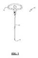
- FIG. 1is a plan view of an example of a pedicle access system according to one embodiment of the present invention
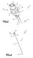
- FIG. 2is a perspective view of a cannula forming part of the pedicle access system of FIG. 1 ;
- FIG. 3is a perspective view of a coupling element forming part of the cannula of FIG. 2 ;
- FIG. 4is a perspective view of a stylet forming part of the pedicle access system of FIG. 1 ;
- FIG. 5is a perspective view of a locking cap forming part of the stylet of FIG. 4 ;
- FIG. 6is a perspective view of the distal portion of the stylet of FIG. 4 protruding from the distal region of the cannula of FIG. 2 ;
- FIG. 7is a perspective view of the distal portion of the stylet of FIG. 4 protruding from the distal region of the cannula of FIG. 2 , with the distal region of the cannula having an non-insulated portion;
- FIG. 8is a perspective view of the distal portion of the stylet of FIG. 4 protruding from the distal region of the cannula of FIG. 2 , with the distal region of the cannula having a directional electrode;
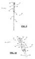
- FIGS. 9-10are plan and perspective views, respectively, of the stylet of FIG. 4 partially inserted into the cannula of FIG. 2 ;
- FIG. 11is a is a plan view of the stylet of FIG. 4 fully inserted into the cannula of FIG. 2 in an unlocked position;
- FIG. 12is perspective view of the locking cap of the fully inserted stylet of FIG. 11 , shown in an unlocked position;
- FIG. 13is a perspective view of the cannula and stylet combination in the unlocked position of FIG. 11 ;
- FIGS. 14-15are perspective and plan views, respectively, of the cannula and stylet combination of FIG. 13 in the locked position;
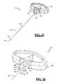
- FIGS. 16-17are perspective views of a T-handle forming part of the pedicle access system of FIG. 1 ;
- FIG. 18is a perspective view of the pedicle access system of FIG. 1 with the cannula and stylet combination of FIG. 13 fully inserted and locked in the T-handle;
- FIG. 19is an exploded perspective view of a pedicle access system according to an alternative embodiment of the present invention.
- FIG. 20is a perspective view of the assembled pedicle access system of FIG. 19 ;
- FIGS. 21-22are plan and perspective views, respectively, of a cannula forming part of the pedicle access system of FIG. 20 ;
- FIGS. 23-24are plan and perspective views, respectively, of a coupling element forming part of the cannula of FIG. 21 ;
- FIG. 25is a perspective view of a stylet forming part of the pedicle access system of FIG. 20 ;
- FIG. 26is a perspective view of a handle forming part of the stylet of FIG. 25 ;
- FIG. 27is a perspective view of the pedicle access system of FIG. 20 including an enlarged view of a distal region thereof;
- FIGS. 28-30are perspective, top plan and bottom plan views, respectively, of a lock collar forming part of the pedicle access system of FIG. 20 ;
- FIG. 31is an exploded perspective view of a pedicle access system according to a further alternative embodiment of the present invention.
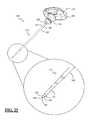
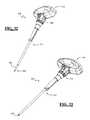
- FIGS. 32-33are perspective views of an assembled pedicle access system of FIG. 31 ;
- FIG. 34is a front view of the pedicle access system of FIG. 32 ;
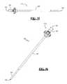
- FIGS. 35-36are side and perspective views, respectively, of a cannula forming part of the pedicle access system of FIG. 31 ;
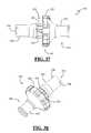
- FIGS. 37-38are side and perspective views, respectively, of a coupling element forming part of the cannula of FIG. 35 ;
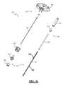
- FIG. 39is a perspective view of a stylet forming part of the pedicle access system of FIG. 31 ;
- FIG. 40is a perspective view of a needle forming part of the stylet of FIG. 39 ;
- FIGS. 41-42are perspective and plan views, respectively, of a handle forming part of the stylet of FIG. 39 ;
- FIGS. 43-44are perspective and plan views, respectively, of a lock collar forming part of the pedicle access system of FIG. 31 ;
- FIG. 45is a bottom plan view of a handle of FIG. 46 in engagement with a lock collar of FIG. 43 ;
- FIG. 46is a perspective view of a retractable insulation sheath forming part of the pedicle access system of FIG. 31 ;
- FIG. 47is a perspective view of an insulation tube forming part of the retractable insulation sheath of FIG. 46 ;
- FIG. 48is a perspective view of a retraction tube forming part of the retractable insulation sheath of FIG. 46 ;
- FIGS. 49-50are perspective views of a sheath attachment element forming part of the pedicle access system of FIG. 31 ;
- FIG. 51is an exploded perspective view of a pedicle access system according to a further alternative embodiment of the present invention providing directionality during use;
- FIGS. 52-53are side and perspective views, respectively, of a cannula forming part of the pedicle access system of FIG. 51 ;
- FIG. 53Aare cross-sectional views taken along lines 53 A- 53 A in FIG. 53 illustrating the relative size of the insulated and non-insulated regions of the cannula of FIGS. 51-53 ;
- FIG. 54is a perspective view of an example of a neurophysiology system capable of connecting to the pedicle access systems of FIGS. 1 , 19 and 31 to conduct pedicle integrity tests.
- FIG. 1illustrates an example of a pedicle access system 10 according to one embodiment of the present invention.
- the pedicle access system 10includes a cannula 12 , a stylet 14 , and a T-handle 16 .
- the pedicle access system 10may be used in conjunction with a neurophysiologic monitoring system (as described herein or otherwise commercially available) to percutaneously approach the pedicle, initiate pilot hole formation, and conduct a stimulation signal to the target site for the purposes of performing a pedicle integrity assessment during formation of the pilot hole.
- the cannula 12 and stylet 14may be lockingly mated to form a cannula/stylet combination 15 (e.g. FIG.
- the T-handle 16may be detached from the cannula/stylet combination 15 to facilitate the use of various surgical tools (such as by way of example only a forceps, mallet, or needle driver) after proper positioning of the cannula 12 and stylet 14 .
- the cannula 12 and stylet 14are generally cylindrical in shape. However, it should be understood that cannula 12 and stylet 14 may be provided in any suitable shape having any suitable cross-section (e.g. generally oval or polygonal) without deviating from the scope of the present invention.
- FIG. 2illustrates an example of a cannula 12 forming part of pedicle access system 10 .
- Cannula 12includes a coupling element 18 and an elongated shaft 20 .
- An interior lumenextends through the cannula 12 from a first opening 22 located at a proximal region 30 of the coupling element 18 to a second opening 24 located at a distal end 21 of the elongated shaft 20 .
- Elongated shaft 20may be composed of any conductive material such as (by way of example only) metal.
- a polymeric coatingis provided on a substantial portion of the exterior surface of elongated shaft 20 such that elongated shaft 20 comprises an insulated portion 26 and an uninsulated portion 28 .
- elongated shaft 20is shown having a single uniform diameter, it will be appreciated that one or more diameter changes may be incorporated along the elongated shaft 20 without deviating from the scope of the present invention.
- coupling element 18comprises a proximal region 30 , a center section 32 , and a base portion 34 .
- Proximal region 30is dimensioned to engage with the stylet 14 (described below).
- Proximal region 30may include at least one tab member 36 that protrudes in a generally lateral direction from the proximal region 30 .
- proximal region 30includes two tab members 36 positioned opposite one another and adjacent to first opening 22 .
- tab members 36function to lock the cannula 12 and stylet 14 together.
- Center section 32is dimensioned to be received within T-handle aperture 66 ( FIG. 16 ) as described in further detail below.
- Center section 32may be provided with at least one cutout 38 dimensioned to receive a locking mechanism 68 ( FIG. 16 ) incorporated into T-handle 16 to secure the T-handle 16 to the cannula/stylet combination 15 , or optionally to the cannula 12 only.
- the base 34has a circumference that is greater than the circumference of center section 32 , such that a ledge 39 is formed at the interface of center section 32 and the base portion 34 .
- the ledge 39engages the rim 72 of T-handle 16 so as to minimize potential stress on a T-handle locking mechanism 68 discussed below.
- FIG. 4illustrates an example of a stylet 14 forming part of the pedicle access system 10 .
- Stylet 14includes a locking cap 40 and a needle element 42 .
- Locking cap 40has a similar size and shape to center section 32 , and is similarly dimensioned to be received within T-handle aperture 66 , discussed below.
- Locking cap 40includes a distal end 44 and a proximal end 46 .
- locking cap 40includes a generally cylindrical aperture 48 having an opening at distal end 44 and extending in a proximal direction at least partially the length of locking cap 40 .
- Generally cylindrical aperture 48is dimensioned to receive the generally cylindrical proximal region 30 of cannula 12 .
- locking cap 40includes at least one longitudinal channel 50 (defined by an axis extending through the proximal and distal ends 46 , 44 respectively) and at least one lateral channel 52 extending generally perpendicularly from longitudinal channel 50 .
- Longitudinal channel 50 and lateral channel 52each extend from an exterior surface 54 through an interior surface 56 into aperture 48 .
- the number of longitudinal channels 50 and lateral channels 52correspond to the number of tab members 36 on cannula 12 .
- cannula 12includes two tab members 36 and stylet 14 includes two longitudinal channels 50 and two lateral channels 52 .
- Longitudinal channel 50initiates at the distal end 46 and has a length corresponding to the length of the generally cylindrical 48 .
- Lateral channel 52initiates at the proximal end of longitudinal channel 50 and extends generally perpendicularly therefrom such that together the longitudinal and lateral channels 50 , 52 form a generally half-T shape.
- Longitudinal channel 50 and lateral channel 52function to interact with the tab 36 on cannula 12 , so as to lock the stylet 14 and cannula 12 together.
- Longitudinal channel 50has a width dimension sufficient to accommodate the length of tab member 36 and lateral channel 52 has a height dimension sufficient to accommodate the height of tab member 36 (best viewed in FIG. 12 ).
- a ridge 58(shown in FIG.
- a portion of exterior surface 54 adjacent to proximal end 46may comprise a ramped surface 49 such that the circumference of distal end 44 is slightly greater than the circumference of proximal end 46 , so as to facilitate engagement with the T-handle 16 .
- the needle element 42comprises an elongated shaft 41 having a proximal region 43 and a distal region 45 .
- the proximal region 43may be attached to the interior of locking cap 40 between proximal end 46 and aperture 48 .
- Elongated shaft 41extends distally from proximal region 43 with a significant portion protruding generally perpendicularly from the opening of aperture 48 .
- Needle element 42is dimensioned to be inserted through the interior lumen of cannula 12 .
- the distal region 45generally includes a distal portion of elongated shaft 41 and a shaped tip 47 having any form or shape capable of being driven into the pedicle to create a pilot hole.
- shaped tip 47may have a beveled or double diamond form. As illustrated in FIG. 6 , when needle element 42 is fully inserted into cannula 12 , at least a portion of distal region 45 (including shaped tip 47 ) may protrude slightly from the second opening 24 of cannula 12 . Due to the insulated nature of cannula 12 , the portion of needle element 42 that protrudes from cannula 12 effectively constitutes a stimulation region 60 .
- the stimulation region 60may include the distal region 45 and/or the shaped tip 47 .
- any part of the needle element 42may be provided with a coating to insulate and therefore limit or reduce the stimulation region 60 to a desired configuration.
- the distal tip 47may have an insulation coating to effectuate a stimulation region 60 consisting of the portion of the distal region 45 of the needle element 42 between the insulated cannula 12 and the insulated distal tip 47 .
- the entirety of needle element 42may be provided with an insulative coating and the distal region 21 of cannula 12 may be provided with (for example) one or more non-insulated portions 29 ( FIG.
- Needle element 42may be composed of a conductive material, such as metal.
- needle element 42may be composed of a non-conductive material with one or more embedded conductive elements at or near the distal end (e.g. distal region 45 and/or shaped tip 47 ) capable of being communicatively linked with a pedicle integrity testing system.
- FIGS. 9-15illustrate the formation of the cannula/stylet combination 15 .
- stylet 14is introduced into cannula 12 .
- Needle element 42 of stylet 14is inserted into the interior lumen of cannula 12 through the first opening 22 of coupling element 18 .
- the locking cap 40 of stylet 14is positioned such that its longitudinal channels 50 are aligned with the tab members 36 of cannula 12 .
- the proximal region 30 of cannula 12is received into the aperture 48 of locking cap 40 , and the tab members 36 pass through the longitudinal channels 50 as insertion of needle element 42 progresses.
- Insertionis complete when the proximal portion 30 is fully received by aperture 48 , leaving the locking cap 40 in the “unlocked” position illustrated in FIGS. 11-13 .
- the distal region 45 of needle element 42 including shaped tip 47 (and the stimulation region 60 )may protrude from the second opening 24 of the elongated shaft 20 of cannula 12 when stylet 14 is fully inserted, shown in FIG. 11 .
- tab members 36are positioned at the proximal end of longitudinal channels 50 where the channels intersect lateral channels 52 .
- the corresponding shapes of the locking cap 40 of stylet 14 and center section 32 of cannula 12are out of alignment.
- the locking cap 40is rotated until it is aligned with the center section 32 as illustrated in FIGS. 14-15 .
- ridges 58come into contact with the tab members 36 .
- the ridgesmay not pass the tab members 36 if the locking cap 40 is not rotated with enough force to deform the ridges 58 .
- the rotationmay continue towards the final position.
- the locking cap 40 and center section 32become aligned and the ridges 58 may clear the tab members 36 and regain their original forms, thereby preventing inadvertent rotation of the locking cap 40 back to the unlocked position.
- FIG. 16illustrates an example of a T-handle 16 forming part of the pedicle access system 10 .
- T-handle 16includes a grip region 64 , an aperture 66 for engaging the cannula 12 or cannula/stylet combination 15 , and a locking mechanism 68 for securing the T-handle to the cannula 12 .
- Grip region 64may be provided in any number of suitable shapes and sizes that may aid the user in holding and manipulating the pedicle access system 10 during use.
- the T-handle aperture 66is dimensioned to snugly receive both the locking cap 40 and center section 32 when they are aligned in the locked position as described above.
- the locking mechanism 68preferably comprises a lever having one end that is integrated into the aperture wall and a free end 70 extending therefrom.
- the majority of the locking mechanism 68(excluding free end 70 ) may comprise the same thickness as the aperture wall and does not protrude, interiorly or exteriorly, from the aperture wall.
- the interior surface of free end 70protrudes into the aperture 66 space.
- the interior surface of free end 70is dimensioned to engage the cutout 38 in the center section 32 of cannula 12 .
- the interior surface of free end 70may be slightly ramped, such that the edge further from the aperture opening protrudes further into the aperture than the edge closer to the aperture opening.
- the ramped portionworks in concert with the ramped surface 49 at the proximal end 46 of locking cap 40 to force the free end 70 out of its natural state as the locking cap 40 of stylet 14 and center section 32 of cannula 12 are received into the T-handle aperture 66 .
- the interior surface of free end 70aligns with the cutout 38 in the center section 32 and free end 70 returns to its natural state, thus locking the T-handle 16 to the cannula 12 .
- the ledge 39engages the rim 72 .
- T-handle 16This interaction functions to minimize potential stress on the T-handle locking mechanism 68 by increasing the surface area that receives force applied by the user.
- the free end 70may be lifted to disengage with the cutout 38 , and the T-handle may be pulled off.
- T-handle 16may be cannulated (not shown) such that an interior lumen extends from an opening on the top of the handle into the aperture 66 .
- FIGS. 19-20illustrate an example of a pedicle access system 110 according to an alternative embodiment of the present invention.
- the pedicle access system 110includes a cannula 112 , a stylet 114 , and a lock collar 116 .
- pedicle access system 110may be used to percutaneously approach the pedicle, initiate pilot hole formation, and conduct a stimulation signal to the target site for the purposes of performing a pedicle integrity assessment during formation of the pilot hole.
- the cannula 112 and stylet 114may be lockingly mated and inserted through an operating corridor to the pedicle target site, using the handle portion 140 of the stylet 114 to facilitate easy movement and positioning of pedicle access system 110 .
- the pedicle access system 110may be driven into the bone at the target site to form a pilot hole while a stimulation signal is applied and conducted to the target site to assess the integrity of the pedicle during hole formation.
- the cannula 112 and stylet 114are generally cylindrical in shape. However, it should be understood that cannula 112 and stylet 114 may be provided in any suitable shape having any suitable cross-section (e.g. generally oval or polygonal) without deviating from the scope of the present invention.
- FIGS. 21-22illustrate an example of a cannula 112 forming part of pedicle access system 110 .
- Cannula 112includes a coupling element 118 and an elongated shaft 120 .
- An interior lumenextends through the cannula 112 from a first opening 122 located at a proximal region 130 of the coupling element 118 to a second opening 124 located at a distal end 121 of the elongated shaft 120 .
- Elongated shaft 120may be composed of any conductive material such as metal, for example.
- a polymeric coatingmay be provided on a substantial portion of the exterior surface of elongated shaft 120 such that elongated shaft 120 comprises an insulated portion 126 and an non-insulated portion 128 (the edge of the coating and thus the boundary between portions 126 , 128 represented by callout 127 in FIGS. 21-22 ).
- Elongated shaft 120may include any number of diameter changes incorporated along its length without deviating from the scope of the present invention. In the alternative, elongated shaft 120 may be provided with a uniform diameter along its length.
- coupling element 118comprises a proximal region 130 , a center section 132 , and a distal portion 134 .
- Proximal region 130includes an engagement region 131 dimensioned to engage with the handle portion 140 of the stylet 114 (as described in further detail below).
- the engagement region 121may be provided in any suitable geometric configuration to allow for secure mating with the engagement tabs 144 of the handle 140 .
- the coupling element 118is shown in FIGS. 23-24 having a hexagonal engagement region 131 , however other shapes are possible.
- Proximal region 130may include at least one tab member 136 that protrudes in a generally lateral direction from the proximal region 130 .
- proximal region 130includes two tab members 136 positioned opposite one another and adjacent to first opening 122 .
- Tab members 136may be utilized to attach supplemental instruments and/or apparatuses to the cannula 112 .
- Center section 132may be provided with a diameter that is larger than the diameters of the proximal region 130 and distal portion 134 , and may be provided with a plurality of ridges 133 and/or other features for the purpose of providing a suitable gripping area for a user.
- the distal portion 134is dimensioned to engage with the elongated shaft 120 of the cannula 112 .
- FIG. 25illustrates an example of a stylet 114 forming part of the pedicle access system 110 .
- Stylet 114includes a handle portion 140 and a needle element 142 .
- Handle portion 140may (by way of example) resemble a T-handle for providing a user with a suitable gripping means.
- Handle portion 140may be provided with a pair of engagement tabs 144 extending distally from handle portion 140 .
- Engagement tabs 144extend generally perpendicularly from the handle 140 and generally parallel to one another such that the engagement tabs 144 collectively form an interior space 146 .
- Interior space 146is dimensioned to receive the proximal region 130 of the coupling element 118 of the cannula 112 .
- Each engagement tab 144is provided with a medial (inwardly-facing) indentation 148 and a lateral (outwardly-facing) indentation 150 .
- Medial indentations 148are dimensioned to engage the engagement region 131 of the coupling element 118 , described above.
- the medial indentations 148may be provided with any geometry complementary to the shape of the engagement region 131 such that when mated, the engagement tabs 144 (via the medial indentations 148 ) will prevent movement of the engagement region 131 , in effect locking the cannula 112 in place relative to the stylet 114 .
- the lateral indentations 150are dimensioned to interact with the first and second protrusions 170 , 172 of the lock collar 116 described in further detail below.
- the needle element 142comprises an elongated shaft 152 having a proximal region 154 and a distal region 156 .
- the proximal region 154may be attached to the interior of handle portion 140 .
- Elongated shaft 152extends distally from proximal region 154 and generally perpendicularly from the handle 140 .
- Needle element 142is dimensioned to be inserted through the interior lumen of cannula 112 .
- the distal region 156generally includes a distal portion of elongated shaft 152 and a shaped tip 158 having any form or shape capable of being driven into the pedicle to create a pilot hole.
- shaped tip 158may have a beveled or double diamond form. As illustrated in FIG.
- distal region 156when needle element 142 is fully inserted into cannula 112 , at least a portion of distal region 156 (including shaped tip 158 ) may protrude slightly from the second opening 124 of cannula 112 . Due to the insulated nature of cannula 112 , the portion of needle element 142 that protrudes from cannula 112 effectively constitutes a stimulation region 160 .
- the stimulation region 160may include the distal region 152 and/or the shaped tip 158 .
- any part of the needle element 142may be provided with a coating to insulate and therefore limit or reduce the stimulation region 160 to a desired configuration.
- the distal tip 158may have an insulation coating to effectuate a stimulation region 160 consisting of the portion of the distal region 156 of the needle element 142 between the insulated cannula 112 and the insulated distal tip 158 .
- This coatingserves to mitigate an apparent phenomenon in which certain geometries (e.g. points and edges) tend to generate significantly higher current densities and therefore are much more efficient at exciting a nearby nerve, even through bone tissue.
- Needle element 142may be composed of any conductive material, such as metal.
- needle element 142may be composed of a non-conductive material with one or more embedded conductive elements at or near the distal end (e.g. distal region 156 and/or shaped tip 158 ) capable of being communicatively linked with a pedicle integrity testing system.
- Lock collar 116is provided to lockingly mate the cannula 112 and the stylet 114 .
- Lock collar 116has a generally cylindrical overall shape, and includes a proximal portion 162 , a distal portion 164 and an interior lumen 166 extending therethrough.
- the proximal portion 162may have a diameter greater than that of the distal portion 164 and is provided with a plurality of friction elements 168 to allow a user to grasp and turn the lock collar 116 .
- the distal portion 164includes a generally oval-shaped opening 170 providing access to the lumen 166 .
- the opening 170further includes a pair of opposing first protrusions 172 and a pair of opposing second protrusions 174 located along the inside edge of opening 170 .
- First protrusions 172are located 180° from one another and are positioned at the long ends of the oval-shaped opening 170 .
- Second protrusions 174are positioned at the narrow sides of the oval-shaped opening 170 (and thus are located at 90° intervals from the first protrusions 172 and 180° from one another).
- First and second protrusions 172 , 174are each dimensioned to engage the lateral indentations 150 provided on the engagement tabs 144 of the handle 140 , described above.
- the interior lumen 166is dimensioned to receive both of the engagement tabs 144 of the handle 140 .
- the pedicle access system 110 of the present inventionmay be provided with the locking collar 116 attached to the stylet 114 in an initial position. This initial position is defined by the first protrusions 172 resting in the lateral indentations 150 of the engagement tabs 144 of the handle 140 .
- the distal region 130 of the coupling element 118 of cannula 112will enter the space 146 of the handle 140 such that the medial indentations 148 are aligned with (but not yet engaging) the engagement region 131 of the coupling element 118 .
- FIGS. 31-34illustrate an example of a pedicle access system 210 according to a further alternative embodiment of the present invention.
- the pedicle access system 210includes a cannula 212 , a stylet 214 , a lock collar 216 and a retractable insulation sheath 217 .
- pedicle access system 210may be used to percutaneously approach the pedicle, initiate pilot hole formation, and conduct a stimulation signal to the target site for the purposes of performing a pedicle integrity assessment during formation of the pilot hole.
- the cannula 212 and stylet 214may be lockingly mated and inserted through an operating corridor to the pedicle target site, using the handle portion 240 of the stylet 214 to facilitate easy movement and positioning of pedicle access system 210 .
- the pedicle access system 210may be driven into the bone at the target site to form a pilot hole while a stimulation signal is applied and conducted to the target site to assess the integrity of the pedicle during pilot hole formation.
- the retractable insulation sheath 217functions to ensure maximum efficiency of the stimulation signal as by limiting or preventing shunting of the signal during pilot hole formation.
- the cannula 212 , stylet 214 and retractable insulation sheath 217are generally cylindrical in shape. However, it should be understood that cannula 212 , stylet 214 and sheath 217 may be provided in any suitable shape having any suitable cross-section (e.g. generally oval or polygonal) without deviating from the scope of the present invention.
- the retractable insulation sheath 217functions to ensure maximum efficiency of the stimulation signal as by limiting or preventing shunting of the signal during pilot hole formation. With specific reference to FIGS. 32-34 , this is accomplished by providing a tubular insulation member 274 slidably mated with a housing member 276 described in greater detail below. In an initial position (shown in FIGS. 33-34 ), the tubular insulation member 274 is fully extended such that it extends at least to the tip 258 of the stylet 214 . Upon formation of a pilot hole in a pedicle (or other piece of bone), the stylet 214 will advance into the bone while the insulation sheath remains outside the bone (a position shown by way of example in FIG. 32 ).
- the electrical current when suppliedwill be directed into the pilot hole by the non-insulated portion of the cannula 212 and stylet 214 while prevented from shunting outside of the hole by the sheath 217 .
- Thishas the effect of reducing the current density of the applied stimulation signal as the exposed surface area of the non-insulated portion of the cannula 212 and the stylet 214 increases during introduction.
- FIGS. 35-36illustrate an example of a cannula 212 forming part of pedicle access system 210 of the present invention.
- Cannula 212includes a coupling element 218 and an elongated shaft 220 .
- An interior lumenextends through the cannula 212 from a first opening 222 located at a proximal region 230 of the coupling element 218 to a second opening 224 located at a distal end 221 of the elongated shaft 220 .
- Elongated shaft 220may be composed of any conductive material such as metal, for example.
- Elongated shaft 220may include any number of diameter changes incorporated along its length without deviating from the scope of the present invention. In the alternative, elongated shaft 220 may be provided with a uniform diameter along its length.
- coupling element 218comprises a proximal region 230 , a center section 232 , and a distal portion 234 .
- Proximal region 230includes an engagement region 231 dimensioned to engage with the handle portion 240 of the stylet 214 (as described in further detail below).
- the engagement region 231may be provided in any suitable geometric configuration to allow for secure mating with the engagement tabs 144 of the handle 140 .
- the coupling element 218is shown in FIGS. 37-38 having a plurality of triangular-shaped indentations 233 , however other shapes are possible.
- Proximal region 230may include at least one tab member 236 that protrudes in a generally lateral direction from the proximal region 230 .
- proximal region 230includes two tab members 236 positioned opposite one another and adjacent to first opening 222 .
- Tab members 236may be utilized to attach supplemental instruments and/or apparatuses to the cannula 212 .
- Center section 232may be provided with a diameter that is larger than the diameters of the proximal region 230 and distal portion 234 , and may be provided with a plurality of ridges 235 and/or other features for the purpose of providing a suitable gripping area for a user.
- the distal portion 234is dimensioned to engage with the elongated shaft 220 of the cannula 212 and may further be provided with a recess 237 for engagement with the sheath attachment element 292 , described in further detail below.
- FIG. 39illustrates an example of a stylet 214 forming part of the pedicle access system 210 .
- Stylet 214includes a handle portion 240 and a needle element 242 .
- the handle portion 240may (by way of example) resemble a T-handle for providing a user with a suitable gripping means.
- the handle portion 240may have a substantially hollow interior that is not fully enclosed.
- Handle portion 240includes an aperture 243 and a pair of engagement tabs 244 extending distally from handle portion 240 .
- Aperture 243is dimensioned to allow passage of the needle element 242 from the handle portion 240 .
- Engagement tabs 244extend generally perpendicularly from the handle 240 and generally parallel to one another such that the engagement tabs 244 collectively form an interior space 246 .
- Interior space 246is dimensioned to receive the proximal region 1230 of the coupling element 218 of the cannula 212 .
- Each engagement tab 244is provided with a medial (inwardly-facing) protrusion 248 .
- Medial protrusions 248are dimensioned to engage the engagement region 231 of the coupling element 218 , described above.
- the medial protrusions 248may be provided with any geometry complementary to the shape of the engagement region 231 such that when mated, the engagement tabs 244 (via the medial protrusions 248 ) will prevent movement of the engagement region 231 , in effect locking the cannula 212 in place relative to the stylet 214 .
- the needle element 242comprises an elongated shaft 252 having a proximal region 254 and a distal region 256 .
- the proximal region 254includes an attachment element 257 configured to attach to the interior of handle portion 240 .
- the attachment element 257is configured to provide a point of contact for an instrument, including but not limited to a clip attached to an electrical source and/or a device capable of detecting the position (e.g. tilt) of the assembly 210 during use.
- a tilt sensoris shown and described in co-pending and commonly owned U.S. Provisional Patent Application No.
- the attachment element 257may also include a ring element 261 located (by way of example only) at its proximal end.
- the ring element 261does not extend around the entire periphery of the attachment element 257 and thereby forms a notch 259 .
- the notch 259is adapted to receive a male mating feature provided on the instrument (e.g. clip for attachment to electrical stimulation source and/or “tilt sensor”) for the purpose of maintaining the instrument and the assembly 210 in a fixed position relative to one another.
- Elongated shaft 252extends distally from proximal region 254 and generally perpendicularly from the handle 240 (and through aperture 243 ). Needle element 242 is dimensioned to be inserted through the interior lumen of cannula 212 .
- the distal region 256generally includes a distal portion of elongated shaft 252 and a shaped tip 258 having any form or shape capable of being driven into the pedicle to create a pilot hole.
- shaped tip 258may have a beveled or double diamond form.
- distal region 256may protrude slightly from the second opening 224 of cannula 212 .
- Needle element 242may be composed of any conductive material, such as metal.
- needle element 242may be composed of a non-conductive material with one or more embedded conductive elements at or near the distal end (e.g. distal region 256 and/or shaped tip 258 ) capable of being communicatively linked with a pedicle integrity testing system.
- the stylet 214is preferably provided as a single unit, with the needle element 242 and attachment element 257 molded in place in the handle 240 .
- Lock collar 216is provided to lockingly mate the cannula 212 and the stylet 214 .
- Lock collar 216has a generally cylindrical overall shape, and includes a proximal portion 262 , a distal portion 264 and an interior lumen 266 extending therethrough.
- the proximal portion 262may have a diameter greater than that of the distal portion 264 and is provided with a plurality of friction elements 268 to allow a user to grasp and turn the lock collar 216 .
- the distal portion 264includes a generally oval-shaped opening 270 providing access to the lumen 266 .
- the opening 270further includes a pair of opposing protrusions 272 located along the inside edge of opening 270 .
- Protrusions 272are located 180° from one another and are positioned approximately midway between the “long ends” and the “narrow sides” of the oval-shaped opening 270 . Protrusions 272 are dimensioned to engage the sides of engagement tabs 244 of the handle 240 , described above.
- the interior lumen 266is dimensioned to receive both of the engagement tabs 244 of the handle 240 .
- the pedicle access system 210 of the present inventionmay be provided with the locking collar 216 attached to the stylet 214 in an initial position. This initial position is defined by the protrusions 272 resting alongside the engagement tabs 244 of the handle 240 .
- the engagement tabs 244 at this pointare disposed in the “long ends” of the oval-shaped opening 270 .
- the distal region 230 of the coupling element 218 of cannula 212will enter the space 246 of the handle 240 such that the medial protrusions 248 are aligned with (but not yet engaging) the engagement region 231 of the coupling element 218 .
- a userwould then rotate the lock collar 216 90° to a second position such that the protrusions 272 rest in against the engagement tabs 244 and the engagement tabs 244 rest in the “narrow sides” of the oval-shaped opening 270 , as shown in FIG. 45 .
- the engagement tabs 244will be forced toward one another, and the medial protrusions 248 will come in contact with and positively engage the engagement region 231 . As noted previously, this positive engagement prevents the cannula 212 from moving.
- the lock collar 216serves to lock the engagement tabs 214 in place, effectively locking the cannula 212 and the stylet 214 together.
- the pedicle access system 210is now ready for use.
- the insulation tubecomprises a cannulated, elongated and generally cylindrical member having a proximal end 278 and a distal end 280 .
- the proximal end 278includes at least one tab 282 configured to slidably engage the housing member 276 as set forth below.
- the insulation tube 274includes a pair of tabs 282 positioned opposite one another, however any number of tabs 282 may be provided without departing from the scope of the invention.
- the distal end 280may be provided with a generally tapered surface 284 to allow for an improved interface with the bone.
- the housing member 276comprises an elongated generally cylindrical member having a proximal end 286 , a distal end 287 and an interior lumen 288 .
- the proximal end 286includes a shaped engagement feature 289 (e.g. a recess as shown) dimensioned to engage a sheath attachment element 292 described in further detail below.
- the housing member 276further includes at least one elongated track 290 in the form of a cutout section extending substantially the length of the housing member 276 .
- the track 290is dimensioned to slidably receive the tabs 282 of the insulation tube 274 such that the insulation tube 274 is allowed to migrate within the lumen 288 .
- the sheath attachment element 292may be provided as a generally cylindrical member having an interior lumen 293 .
- Sheath attachment element 292is dimensioned to provide a snap-fit engagement with both the housing member 276 and the coupling element 218 of cannula 212 .
- the lumen 293is provided with a first ridge 294 near a distal end for secure engagement with recess 289 of the housing member 276 .
- the lumen 293is provided with a second ridge (not shown) near a proximal end for engagement with recess 237 of the coupling element 218 ( FIG. 37 ).
- the retractable insulation sheath 217may be provided with the sheath attachment element 292 mated to the housing member 276 .
- the cannula 212is then inserted into the insulation sheath 217 and sheath attachment element 292 will then engage the coupling element 218 , thus securely attaching the insulation sheath 217 to the pedicle access system 210 .
- the pedicle access system 210is provided with the insulation tube 274 in a first, fully extended position (e.g. FIG. 33 ).
- the insulation tube 274will remain in this position as the pedicle access system 210 is advanced through an operative corridor to a bony target site (e.g. a pedicle).
- a bony target sitee.g. a pedicle.
- the tip 258 of the needle element 242 and the distal end 280 of the insulation tube 274may contact the bone at approximately the same time.
- the usermay want to begin monitoring the integrity of the pilot hole formation by using a stimulation signal as described below.
- the distal end 280remains engaged to the outside surface of the bone.
- the proximal end 278 (including tabs 282 ) of the insulation tubewill advance proximally along the track 290 of the housing member 276 .
- the portion of needle element 242 and cannula 212 that protrude from insulation tube 274effectively constitute a stimulation region 260 ( FIG. 32 ).
- the stimulation region 260becomes larger.
- the needle 242 and cannula 212are withdrawn from the bony structure, and the pedicle access system 210 may be removed from the operative corridor.
- a spring(not shown) or other control mechanism may be provided to limit the extent of migration of the insulation tube 274 and/or provide a means for the insulation tube 274 to bias toward returning to the fully extended position upon removal of the needle 242 from the pilot hole in the pedicle.
- the tubular insulation member 274may be biased into an “automatically extended” manner, such as providing a spring member 219 (shown in FIG. 31 ) in between a proximal end member 278 of the tubular insulation member 274 and the housing member 276 , both of which will be described in greater detail below.
- a spring member 219shown in FIG. 31
- the distal end of the spring member 219will abut into the tab elements 282 ( FIG. 47 ) while the proximal end of the spring member 219 will abut a portion within the housing member 276 (preferably at or near the proximal region of the housing member 276 ). This will, in turn, automatically force the tubular insulation member 274 away from housing member 276 .
- the spring member 219preferably has a suitable modulus of elasticity such that it will readily compress to allow the tubular insulation member 274 to be received within the housing member 276 while the stylet 242 is being advanced into the target bone, and expand to its original shape to allow the tubular insulation member 274 to again fully extend from the housing member 276 when the stylet 242 is being withdrawn from the target bone.
- the elongated shaft 220 of the cannula 212is provided with an insulated region 263 and a non-insulated region 265 to provide directionality during use. More specifically, the non-insulated region 265 is conductive during use and transmits the stimulation signal to the surrounding tissue (e.g. bone), while the insulated region 263 is non-conductive and does not transmit the stimulation signal during use. A user may rotate the elongated shaft 220 during stimulation and, by knowing the location of the non-insulated region 265 , gauge the location of any potential breach.
- the readings from the neurophysiologic monitoring systemwill decrease as the non-insulated region 265 is pointed in the direction of the medial wall and will increase as the non-insulated region 265 is pointed away from the medial wall.
- the directionality of this embodimentmay also be used to detect the location of the elongated shaft 220 within the pedicle itself (e.g. whether it's centered or not) using the same principle. That is, if the neurophysiologic readings are approximately equal as the non-insulated region 265 is rotated during stimulation, it would indicate that the elongated shaft 220 is generally centered within the pedicle.
- the non-insulated region 265be provided having any number of different sizes relative to the overall circumference of the elongated shaft 220 , such as a fraction (top of FIG. 53A ), approximately half (middle of FIG. 53A ) or a majority (bottom of FIG. 53A ).
- the pedicle access systems 10 , 110 and 210 described abovemay be used in combination with neurophysiology monitoring systems and methods to conduct pedicle integrity assessments while achieving initial access to the pedicle.
- the pedicle access systems 10 , 110 and 210may be used in combination with the system and methods shown and described in commonly owned and co-pending Int'l Patent App. Ser. No. PCT/US02/22247, filed on Jul. 11, 2002, the contents of which are hereby incorporated by reference into this disclosure as set forth herein in its entirety.
- an example of one such neurophysiology system 300includes a display 301 , a control unit 302 , a patient module 304 , an EMG harness 306 , including eight pairs of EMG electrodes 308 and a return electrode 310 coupled to the patient module 304 , and a host of surgical accessories 312 , including an electric coupling device 316 capable of being coupled to the patient module 304 via one or more accessory cables 314 .
- the neurophysiology system 300performs pedicle integrity assessments by determining the amount of electrical communication between a stimulation signal and the adjacent nerve root. To do this, a stimulation signal is applied to the pilot hole or pedicle screw via one of the surgical accessories 312 .
- the EMG electrodes 308positioned over the appropriate muscles, measure the EMG responses corresponding to the stimulation signal. The relationship between the EMG response and the stimulation signal is then analyzed by the system and the results are conveyed to the user on the display 301 .
- the basic theory underlying the pedicle integrity testis that given the insulating character of bone, a higher stimulation current (or current density) is required to evoke an EMG response when the stimulation signal is applied to an intact pedicle as opposed to a breached pedicle.
- the neurophysiology systemmay be provided with software capable of compensating for multiple safe stimulation thresholds based on different current densities being applied to the pedicle by certain geometries of different instruments.
- the pedicle access systems 10 , 110 and 210 described abovemay be combined to and used in conjunction with the neurophysiology system 300 by attaching (not shown) the electric coupling device 314 to (for example) the non-insulated region 28 of the cannula 12 of pedicle access system 10 .
- the electric coupling device 314may comprise a number of possible embodiments which permit the device to attach and hold a surgical tool (such as the pedicle access system 10 ) while allowing transmission of a stimulation signal to the tool.
- One such electric coupling device 314utilizes a spring-loaded plunger to hold the surgical tool and transmit the stimulation signal.
- the plunger 318is composed of a conductive material such as metal.
- a nonconductive housing 320partially encases the plunger rod 318 about its center.
- Extending from the housing 320is an end plate 324 .
- An electrical cable 326connects the electric coupling device 314 to neurophysiology system 300 .
- a spring(not shown) is disposed within the housing 320 such that in a natural or “closed” state the plunger 318 is situated in close proximity to the endplate 324 . Exerting a compressive force on the spring (such as by pulling the cable 326 while holding the housing 320 ) causes a gap between the end plate 324 and the plunger 318 to widen to an “open” position, thereby allowing insertion of a surgical tool between the end plate 324 and plunger 318 .
- Releasing the cable 326allows the spring to return to a “closed” position, causing the plunger 318 to move laterally back towards the endplate such that a force is exerted upon the surgical tool and thereby holds it in place between the endplate 324 and the plunger 318 . Thereafter the electrical stimulus may be passed from the neurophysiology system 300 through the cable 326 and plunger 318 to the surgical tool.
- the electrical coupling devicemay be embodied in the form of a clip 328 .
- the clip 328is comprised of two prongs hingedly coupled at a coupling point 330 such that the clip 328 includes an attachment end 332 and a non-attachment end 334 .
- a stimulation electrode 336is disposed on the attachment end 332 and communicates with an electric cable 326 extending from the non-attachment end 334 to the neurophysiology system 300 .
- the prong ends at the attachment end 332touch. Depressing the prongs at the non-attachment end 334 in a direction towards each other causes a gap to form between the prong ends at the attachment end 332 .
- the pedicle access system 10may thus be used to safely access the pedicle and safely form a pilot hole.
- the cannula 12 , stylet 14 , and T-handle 16are preferably all combined and locked together as described above.
- the surgeonmay position the stimulation point on the desired target site.
- the electric coupling device 116may be attached to the uninsulated region 28 of cannula 12 and the T-handle 16 may be removed to facilitate the use of a tool such as a needle driver.
- Stimulation signalsare delivered to the pedicle access system 10 and emitted from the stimulation region 60 as it is being driven in to the bone, forming the pilot hole.
- pilot hole formationmay be halted and any steps deemed to be necessary by the surgeon, based on his or her professional judgment, may be taken to correct the problem.
- the electric coupling device 316may be attached before positioning the pedicle access system 10 , and the neurophysiology system 300 may be employed to monitor the proximity of any nerves during positioning.
- the pedicle access system 10may be used in conjunction with spinal fixation systems that require access to pedicle target sites and need pilot holes, including but not limited to those systems shown and described in commonly owned and co-pending U.S. patent application Ser. No. 11/031,506 filed Jan. 6, 2005, and commonly owned and co-pending Int'l Patent App. Ser. No. PCT/US05/032300 filed Sep. 8, 2005.
- the T-handle 16 and stylet 14may be unlocked and removed from the cannula 12 , leaving the cannula 12 positioned in the pilot hole.
- Guide wires subsequently used by the spinal fixation systemsmay then be safely deployed to the pilot hole through the cannula 12 . Once the guide wire is in position the cannula 12 may be removed from the target site and the surgeon may commence use of the surgical fixation system.
Landscapes
- Health & Medical Sciences (AREA)
- Life Sciences & Earth Sciences (AREA)
- Surgery (AREA)
- Veterinary Medicine (AREA)
- Public Health (AREA)
- General Health & Medical Sciences (AREA)
- Animal Behavior & Ethology (AREA)
- Engineering & Computer Science (AREA)
- Biomedical Technology (AREA)
- Heart & Thoracic Surgery (AREA)
- Molecular Biology (AREA)
- Medical Informatics (AREA)
- Pathology (AREA)
- Biophysics (AREA)
- Physics & Mathematics (AREA)
- Nuclear Medicine, Radiotherapy & Molecular Imaging (AREA)
- Neurology (AREA)
- Orthopedic Medicine & Surgery (AREA)
- Radiology & Medical Imaging (AREA)
- Dentistry (AREA)
- Oral & Maxillofacial Surgery (AREA)
- Surgical Instruments (AREA)
- Rheumatology (AREA)
Abstract
Description
Claims (31)
Priority Applications (5)
| Application Number | Priority Date | Filing Date | Title |
|---|---|---|---|
| US11/448,237US7942826B1 (en) | 2005-06-06 | 2006-06-06 | Insulated pedicle access system and related methods |
| US13/109,981US8784330B1 (en) | 2005-06-06 | 2011-05-17 | Insulated pedicle access system and related methods |
| US14/338,154US10517502B1 (en) | 2005-06-06 | 2014-07-22 | Insulated pedicle access system and related methods |
| US15/786,760US11213236B2 (en) | 2005-06-06 | 2017-10-18 | Insulated pedicle access system and related methods |
| US17/532,161US20220079495A1 (en) | 2005-06-06 | 2021-11-22 | Insulated Pedicle Access System and Related Methods |
Applications Claiming Priority (2)
| Application Number | Priority Date | Filing Date | Title |
|---|---|---|---|
| US68794705P | 2005-06-06 | 2005-06-06 | |
| US11/448,237US7942826B1 (en) | 2005-06-06 | 2006-06-06 | Insulated pedicle access system and related methods |
Related Child Applications (1)
| Application Number | Title | Priority Date | Filing Date |
|---|---|---|---|
| US13/109,981ContinuationUS8784330B1 (en) | 2005-06-06 | 2011-05-17 | Insulated pedicle access system and related methods |
Publications (1)
| Publication Number | Publication Date |
|---|---|
| US7942826B1true US7942826B1 (en) | 2011-05-17 |
Family
ID=43981518
Family Applications (5)
| Application Number | Title | Priority Date | Filing Date |
|---|---|---|---|
| US11/448,237Active2029-08-26US7942826B1 (en) | 2005-06-06 | 2006-06-06 | Insulated pedicle access system and related methods |
| US13/109,981ActiveUS8784330B1 (en) | 2005-06-06 | 2011-05-17 | Insulated pedicle access system and related methods |
| US14/338,154ActiveUS10517502B1 (en) | 2005-06-06 | 2014-07-22 | Insulated pedicle access system and related methods |
| US15/786,760Active2028-10-21US11213236B2 (en) | 2005-06-06 | 2017-10-18 | Insulated pedicle access system and related methods |
| US17/532,161PendingUS20220079495A1 (en) | 2005-06-06 | 2021-11-22 | Insulated Pedicle Access System and Related Methods |
Family Applications After (4)
| Application Number | Title | Priority Date | Filing Date |
|---|---|---|---|
| US13/109,981ActiveUS8784330B1 (en) | 2005-06-06 | 2011-05-17 | Insulated pedicle access system and related methods |
| US14/338,154ActiveUS10517502B1 (en) | 2005-06-06 | 2014-07-22 | Insulated pedicle access system and related methods |
| US15/786,760Active2028-10-21US11213236B2 (en) | 2005-06-06 | 2017-10-18 | Insulated pedicle access system and related methods |
| US17/532,161PendingUS20220079495A1 (en) | 2005-06-06 | 2021-11-22 | Insulated Pedicle Access System and Related Methods |
Country Status (1)
| Country | Link |
|---|---|
| US (5) | US7942826B1 (en) |
Cited By (54)
| Publication number | Priority date | Publication date | Assignee | Title |
|---|---|---|---|---|
| US20080108991A1 (en)* | 2006-11-08 | 2008-05-08 | General Electric Company | Method and apparatus for performing pedicle screw fusion surgery |
| US20090105788A1 (en)* | 2007-10-18 | 2009-04-23 | Innovative Surgical Solutions, Llc | Minimally invasive nerve monitoring device and method |
| US20090125072A1 (en)* | 2007-11-13 | 2009-05-14 | Neubardt Seth L | Surgical bone screw construction |
| US20100094115A1 (en)* | 2005-01-31 | 2010-04-15 | Pond Jr John D | Electrically insulated surgical needle assembly |
| US20110230783A1 (en)* | 2007-10-18 | 2011-09-22 | Innovative Surgical Solutions, Llc | Neural event detection |
| US20110230785A1 (en)* | 2010-03-16 | 2011-09-22 | ProNerve, LLC | Somatosensory Evoked Potential (SSEP) Automated Alert System |
| US20110230782A1 (en)* | 2007-10-18 | 2011-09-22 | Innovative Surgical Solutions, Llc | Neural monitoring sensor |
| US20110237974A1 (en)* | 2007-10-18 | 2011-09-29 | Innovative Surgical Solutions, Llc | Neural monitoring system |
| US20120010643A1 (en)* | 2009-04-03 | 2012-01-12 | Weixing Shao | Puncture needle for orthopedic operation |
| US20120330241A1 (en)* | 2006-05-04 | 2012-12-27 | Haddock Sean M | Method for using retractable stylet and cannula combination to form an opening in bone |
| US20130046200A1 (en)* | 2011-08-18 | 2013-02-21 | Marshall Ephraim Stauber | Instrument For Concurrent Injection Of Anesthesia And Removal Of Specimens From A Body |
| US20130116556A1 (en)* | 2011-11-05 | 2013-05-09 | Custom Medical Applications | Neural safety injection system and related methods |
| US20140276596A1 (en)* | 2010-11-01 | 2014-09-18 | Biomet Manufacturing, Llc | Cannulated syringe |
| US8855822B2 (en) | 2012-03-23 | 2014-10-07 | Innovative Surgical Solutions, Llc | Robotic surgical system with mechanomyography feedback |
| US8892259B2 (en) | 2012-09-26 | 2014-11-18 | Innovative Surgical Solutions, LLC. | Robotic surgical system with mechanomyography feedback |
| US8936626B1 (en) | 2012-02-17 | 2015-01-20 | Nuvasive, Inc. | Bi-cortical screw fixation |
| WO2015006876A1 (en)* | 2013-07-19 | 2015-01-22 | Startech Engineering Ag | Coupling device for medical instrument or medical power-tool chuck |
| US8983593B2 (en) | 2011-11-10 | 2015-03-17 | Innovative Surgical Solutions, Llc | Method of assessing neural function |
| US9039630B2 (en) | 2012-08-22 | 2015-05-26 | Innovative Surgical Solutions, Llc | Method of detecting a sacral nerve |
| US9084550B1 (en) | 2007-10-18 | 2015-07-21 | Innovative Surgical Solutions, Llc | Minimally invasive nerve monitoring device and method |
| US9278214B2 (en) | 2007-04-30 | 2016-03-08 | Warsaw Orhtopedic, Inc. | Deformity correction using neural integrity monitoring |
| US9301711B2 (en) | 2011-11-10 | 2016-04-05 | Innovative Surgical Solutions, Llc | System and method for assessing neural health |
| US9427558B2 (en) | 2014-03-17 | 2016-08-30 | Arkis Biosciences | Tunneling guidewire |
| US9622684B2 (en) | 2013-09-20 | 2017-04-18 | Innovative Surgical Solutions, Llc | Neural locating system |
| USD786433S1 (en) | 2016-01-29 | 2017-05-09 | Arkis Biosciences Inc. | Trocar |
| US9681889B1 (en) | 2015-06-09 | 2017-06-20 | Surgentec, Llc | Depth controlled needle assembly |
| US20170238788A1 (en)* | 2015-09-17 | 2017-08-24 | Avery M. Jackson, III | Illuminated Endoscopic Pedicle Probe With Dynamic Real Time Monitoring For Proximity To Nerves |
| US9750508B1 (en)* | 2009-11-11 | 2017-09-05 | Nuvasive, Inc. | Insulated pedicle access system and related methods |
| US9801668B1 (en)* | 2003-05-08 | 2017-10-31 | Nuvasive, Inc. | Neurophysiological apparatus and procedures |
| US9968373B1 (en) | 2014-02-21 | 2018-05-15 | Surgentec, Llc | Handles for needle assemblies |
| USD822830S1 (en) | 2017-04-20 | 2018-07-10 | Arkis Biosciences Inc. | Catheter retention device |
| USD835777S1 (en)* | 2016-10-27 | 2018-12-11 | Arkis Biosciences Inc. | Guidewire stylette |
| US10321833B2 (en) | 2016-10-05 | 2019-06-18 | Innovative Surgical Solutions. | Neural locating method |
| CN110074842A (en)* | 2018-01-25 | 2019-08-02 | 美敦力控股有限责任公司 | It is used together with driver, drill bit and casing to pierce the adapter in bone |
| US10376209B2 (en) | 2013-09-20 | 2019-08-13 | Innovative Surgical Solutions, Llc | Neural locating method |
| US10376208B2 (en) | 2013-09-20 | 2019-08-13 | Innovative Surgical Solutions, Llc | Nerve mapping system |
| US10449002B2 (en) | 2013-09-20 | 2019-10-22 | Innovative Surgical Solutions, Llc | Method of mapping a nerve |
| US10478096B2 (en) | 2013-08-13 | 2019-11-19 | Innovative Surgical Solutions. | Neural event detection |
| US10478097B2 (en) | 2013-08-13 | 2019-11-19 | Innovative Surgical Solutions | Neural event detection |
| CN110547795A (en)* | 2018-05-30 | 2019-12-10 | 张霞玲 | Spinal probe for spinal surgery |
| US10512413B2 (en) | 2014-08-26 | 2019-12-24 | Avent, Inc. | Method and system for identification of source of chronic pain and treatment |
| US10517502B1 (en)* | 2005-06-06 | 2019-12-31 | Nuvasive, Inc. | Insulated pedicle access system and related methods |
| US10751137B2 (en)* | 2013-03-06 | 2020-08-25 | Stryker European Operations Holdings Llc | Modular navigable probe |
| US10870002B2 (en) | 2018-10-12 | 2020-12-22 | DePuy Synthes Products, Inc. | Neuromuscular sensing device with multi-sensor array |
| US10869616B2 (en) | 2018-06-01 | 2020-12-22 | DePuy Synthes Products, Inc. | Neural event detection |
| US10912483B2 (en) | 2018-03-05 | 2021-02-09 | Edge Surgical, Inc. | Handheld devices for use in medical procedures |
| US11168966B2 (en) | 2016-11-03 | 2021-11-09 | Edge Surgical, Inc. | Surgical depth instrument having neuromonitoring capabilities |
| WO2021231130A1 (en)* | 2020-05-11 | 2021-11-18 | Alphatec Spine, Inc | Stimulating targeting needle |
| US11191592B2 (en) | 2007-10-24 | 2021-12-07 | Nuvasive, Inc. | Surgical monitoring system and related methods for spinal pedicle screw alignment |
| CN114191054A (en)* | 2022-02-16 | 2022-03-18 | 真健康(北京)医疗科技有限公司 | Puncture needle clamp and puncture robot |
| US11399777B2 (en) | 2019-09-27 | 2022-08-02 | DePuy Synthes Products, Inc. | Intraoperative neural monitoring system and method |
| US11564719B2 (en) | 2017-06-14 | 2023-01-31 | Edge Surgical, Inc. | Devices for minimally invasive procedures |
| US20230389966A1 (en)* | 2015-05-21 | 2023-12-07 | Nuvasive, Inc. | Methods and instruments for performing leveraged reduction during single position spine surgery |
| US11992227B2 (en) | 2018-03-05 | 2024-05-28 | Edge Surgical, Inc. | Handheld devices for use in medical procedures |
Families Citing this family (9)
| Publication number | Priority date | Publication date | Assignee | Title |
|---|---|---|---|---|
| US9962211B2 (en) | 2015-12-03 | 2018-05-08 | Amendia, Inc. | Handheld instrument assembly |
| US10064632B2 (en) | 2016-02-19 | 2018-09-04 | Rajiv D. Pandya | System and technique for accessing extra articular lesions or abnormalities or intra osseous lesions or bone marrow lesions |
| AU2017340607B2 (en) | 2016-10-05 | 2022-10-27 | Nuvasive, Inc. | Surgical navigation system and related methods |
| US11135089B2 (en)* | 2018-03-09 | 2021-10-05 | Aquesys, Inc. | Intraocular shunt inserter |
| US11612440B2 (en) | 2019-09-05 | 2023-03-28 | Nuvasive, Inc. | Surgical instrument tracking devices and related methods |
| KR20220097901A (en) | 2019-10-08 | 2022-07-08 | 칼튼 이. 스핀들 | Instrument Handles Used in Instrument Alignment Feedback Systems and Methods |
| AU2022242717A1 (en) | 2021-03-22 | 2023-09-07 | Nuvasive, Inc. | Multi-user surgical cart |
| US11931052B2 (en) | 2021-10-08 | 2024-03-19 | Nuvasive, Inc. | Assemblies, systems, and methods for a neuromonitoring drill bit |
| WO2025072668A1 (en)* | 2023-09-29 | 2025-04-03 | Checkpoint Surgical, Inc. | Minimally invasive nerve regeneration systems and method |
Citations (84)
| Publication number | Priority date | Publication date | Assignee | Title |
|---|---|---|---|---|
| US3540447A (en) | 1967-09-29 | 1970-11-17 | Becton Dickinson Co | Spinal needle |
| US3595230A (en) | 1968-07-25 | 1971-07-27 | Abbott Lab | Intravenous catheter placement unit with tubular guide sheath |
| US3598108A (en) | 1969-02-28 | 1971-08-10 | Khosrow Jamshidi | Biopsy technique and biopsy device |
| US3850158A (en) | 1973-07-09 | 1974-11-26 | E Elias | Bone biopsy instrument and method |
| US4230123A (en) | 1978-10-31 | 1980-10-28 | Hawkins Jr Irvin F | Needle sheath complex and process for decompression and biopsy |
| US4256119A (en) | 1979-09-17 | 1981-03-17 | Gauthier Industries, Inc. | Biopsy needle |
| US4262676A (en) | 1979-08-24 | 1981-04-21 | Khosrow Jamshidi | Biopsy needle having integral stylet locking device |
| US4266555A (en) | 1979-11-09 | 1981-05-12 | Khosrow Jamshidi | Biopsy needle with stylet and cannula orientation |
| US4314565A (en) | 1978-03-03 | 1982-02-09 | Lee Peter F | Biopsy and aspiration needle unit |
| US4356828A (en) | 1980-03-03 | 1982-11-02 | Khosrow Jamshidi | Bone marrow aspiration needle |
| US4592369A (en) | 1982-07-12 | 1986-06-03 | National Research Development Corp. | Method and apparatus for use in temporal analysis of waveforms |
| US4609370A (en) | 1983-06-20 | 1986-09-02 | Morrison Peter C | Surgical needle assembly and apparatus for attachment on a surgical needle assembly |
| US4630616A (en) | 1984-06-15 | 1986-12-23 | Berkley And Company, Inc. | Bone marrow needle |
| US4702738A (en) | 1986-05-22 | 1987-10-27 | Spencer Treesa A | Disposable hypodermic syringe and needle combination having retractable, accident preventing sheath |
| US4759377A (en) | 1986-11-26 | 1988-07-26 | Regents Of The University Of Minnesota | Apparatus and method for mechanical stimulation of nerves |
| US4775369A (en)* | 1986-09-09 | 1988-10-04 | Boris Schwartz | Automatically actionable sharpened needle-tip protection |
| US4793363A (en) | 1986-09-11 | 1988-12-27 | Sherwood Medical Company | Biopsy needle |
| US4838282A (en) | 1987-02-26 | 1989-06-13 | Manan Manufacturing Co., Inc. | Bone biopsy needle assembly |
| US4964411A (en) | 1989-07-13 | 1990-10-23 | Empi, Inc. | Evoked EMG signal processing |
| US5147327A (en) | 1990-01-10 | 1992-09-15 | Johnson Gerald W | Hypodermic needle with protective sheath |
| US5151089A (en) | 1990-05-16 | 1992-09-29 | Kirk Iii William D | Retractable protective needle sheath |
| US5196015A (en) | 1992-04-30 | 1993-03-23 | Neubardt Seth L | Procedure for spinal pedicle screw insertion |
| US5201721A (en) | 1991-06-28 | 1993-04-13 | Lee Chooi T | Medical safety needle and method |
| US5242418A (en) | 1992-05-22 | 1993-09-07 | Weinstein James D | Protective means for a needle or similar cannula medical device |
| US5279584A (en) | 1991-12-09 | 1994-01-18 | Square One Medical, Lp | Rotary lock for needle sheaths |
| EP0607688A1 (en) | 1992-12-21 | 1994-07-27 | Seth Lowell Dr. Neubardt | Procedure and system for spinal pedicle screw insertion |
| US5357974A (en) | 1993-03-04 | 1994-10-25 | Thomas F. Robinson | Bone marrow biopsy instrument |
| US5368046A (en) | 1992-09-09 | 1994-11-29 | Symbiosis Corporation | Bone marrow needle assembly |
| US5415645A (en) | 1994-04-29 | 1995-05-16 | Friend; John M. | Retractable sheath for hypodermic needle |
| US5474558A (en) | 1992-04-30 | 1995-12-12 | Neubardt; Seth L. | Procedure and system for spinal pedicle screw insertion |
| US5480440A (en) | 1991-08-15 | 1996-01-02 | Smith & Nephew Richards, Inc. | Open surgical technique for vertebral fixation with subcutaneous fixators positioned between the skin and the lumbar fascia of a patient |
| US5549656A (en) | 1993-08-16 | 1996-08-27 | Med Serve Group, Inc. | Combination neuromuscular stimulator and electromyograph system |
| EP0754431A1 (en) | 1995-07-19 | 1997-01-22 | Medical Biopsy Inc. | Biopsy needle |
| US5645076A (en) | 1991-08-14 | 1997-07-08 | Yoon; Inbae | Automatic retractable safety penetrating instrument |
| US5758655A (en) | 1994-07-21 | 1998-06-02 | Allegiance Corporation | Needle device with improved handle |
| US5928162A (en) | 1995-02-15 | 1999-07-27 | Symbiosis Corporation | Tissue core biopsy cannula |
| US5928163A (en) | 1995-03-31 | 1999-07-27 | Boston Scientific Corporation | Biopsy sampler |
| WO1999056631A1 (en) | 1998-05-07 | 1999-11-11 | Cedars-Sinai Medical Center | Bone marrow aspirator and method therefor |
| US6033369A (en) | 1998-09-23 | 2000-03-07 | Goldenberg; Alec | Disposable handle and needle assembly |
| US6038477A (en) | 1998-12-23 | 2000-03-14 | Axon Engineering, Inc. | Multiple channel nerve stimulator with channel isolation |
| US6063037A (en)* | 1998-08-21 | 2000-05-16 | Manan Medical Products, Inc. | Bone marrow biopsy needle |
| US6104960A (en) | 1998-07-13 | 2000-08-15 | Medtronic, Inc. | System and method for providing medical electrical stimulation to a portion of the nervous system |
| US6110128A (en) | 1998-12-11 | 2000-08-29 | Andelin; John B. | Bone marrow biopsy needle and method for using the same |
| US6181961B1 (en) | 1997-12-16 | 2001-01-30 | Richard L. Prass | Method and apparatus for an automatic setup of a multi-channel nerve integrity monitoring system |
| US6221029B1 (en) | 1999-05-13 | 2001-04-24 | Stryker Corporation | Universal biopsy system |
| WO2001037728A1 (en) | 1999-11-24 | 2001-05-31 | Nuvasive, Inc. | Electromyography system |
| US6261241B1 (en) | 1998-03-03 | 2001-07-17 | Senorx, Inc. | Electrosurgical biopsy device and method |
| US20010029387A1 (en) | 1993-09-07 | 2001-10-11 | Wolf Philip L. | Safety shielded, reusable trocar |
| US6302852B1 (en) | 2000-04-25 | 2001-10-16 | Manan Medical Products, Inc. | Bone marrow biopsy device |
| US6306100B1 (en) | 1997-12-16 | 2001-10-23 | Richard L. Prass | Intraoperative neurophysiological monitoring system |
| US6312394B1 (en) | 2000-04-25 | 2001-11-06 | Manan Medical Products, Inc. | Bone marrow biopsy device |
| US6340351B1 (en) | 1997-09-17 | 2002-01-22 | Alec Goldenberg | Connector for a replaceable biopsy needle |
| US20020072688A1 (en) | 1998-03-03 | 2002-06-13 | Senorx, Inc. | Breast biopsy system and methods |
| US6468279B1 (en) | 1998-01-27 | 2002-10-22 | Kyphon Inc. | Slip-fit handle for hand-held instruments that access interior body regions |
| US6475190B2 (en) | 2001-01-23 | 2002-11-05 | Ispg, Inc. | Needle assembly including a retractable sheath |
| US6554778B1 (en) | 2001-01-26 | 2003-04-29 | Manan Medical Products, Inc. | Biopsy device with removable handle |
| WO2003037170A2 (en)* | 2001-10-30 | 2003-05-08 | Nuvasive, Inc. | System and methods for performing percutaneous pedicle integrity assessments |
| US6579244B2 (en) | 2001-10-24 | 2003-06-17 | Cutting Edge Surgical, Inc. | Intraosteal ultrasound during surgical implantation |
| US6623437B2 (en) | 2001-08-28 | 2003-09-23 | Rex Medical, L.P. | Tissue biopsy apparatus |
| US20030191414A1 (en) | 1999-10-19 | 2003-10-09 | Kyphon Inc. | Hand-held instruments that access interior body regions |
| US6719692B2 (en) | 1999-05-07 | 2004-04-13 | Aesculap Ag & Co. Kg | Rotating surgical tool |
| USD489456S1 (en) | 2002-10-22 | 2004-05-04 | Allegiance Corporation | Biopsy device handle assembly |
| US6796985B2 (en) | 1999-07-01 | 2004-09-28 | Spinevision S.A. | Method for drilling bone, in particular for setting a pedicle screw, equipment, instrument and control device for implementing said method |
| US20040225228A1 (en) | 2003-05-08 | 2004-11-11 | Ferree Bret A. | Neurophysiological apparatus and procedures |
| US6819956B2 (en) | 1998-08-05 | 2004-11-16 | Dilorenzo Daniel J. | Optimal method and apparatus for neural modulation for the treatment of neurological disease, particularly movement disorders |
| US20050033380A1 (en) | 2003-08-04 | 2005-02-10 | Philip Tanner | Method and device for stimulating the brain |
| US6855105B2 (en) | 2001-07-11 | 2005-02-15 | Jackson, Iii Avery M. | Endoscopic pedicle probe |
| WO2005013805A2 (en)* | 2003-08-05 | 2005-02-17 | Nuvasive, Inc. | Systemand methods for performing dynamic pedicle integrity assessments |
| US6875183B2 (en) | 1999-03-19 | 2005-04-05 | Paul Laurence Cervi | Biopsy needle |
| US6929606B2 (en) | 2001-01-29 | 2005-08-16 | Depuy Spine, Inc. | Retractor and method for spinal pedicle screw placement |
| US20050192575A1 (en) | 2004-02-20 | 2005-09-01 | Pacheco Hector O. | Method of improving pedicle screw placement in spinal surgery |
| US20050203441A1 (en) | 2004-03-12 | 2005-09-15 | Voegele James W. | Electrode sleeve for biopsy device |
| US7018343B2 (en) | 2002-04-05 | 2006-03-28 | Allegiance Corporation | Biopsy needle and biopsy device containing the same |
| US7081123B2 (en) | 2002-06-18 | 2006-07-25 | Musculoskeletal Transplant Foundation | Bone marrow aspiration instrument |
| US20060173521A1 (en)* | 2005-01-31 | 2006-08-03 | Pond John D Jr | Electrically insulated surgical needle assembly |
| US7089059B1 (en) | 2000-11-03 | 2006-08-08 | Pless Benjamin D | Predicting susceptibility to neurological dysfunction based on measured neural electrophysiology |
| US20070083167A1 (en) | 2001-03-15 | 2007-04-12 | Specialized Health Products Inc. | Resettable safety shield for medical needles |
| US20070260255A1 (en) | 2006-05-04 | 2007-11-08 | Sdgi Holdings, Inc. | Method for using retractable stylet and cannula combination to form an opening in bone |
| US20070260184A1 (en) | 2006-05-04 | 2007-11-08 | Sdgi Holdings, Inc. | Retractable stylet and cannula combination |
| US20080071302A1 (en) | 2005-06-18 | 2008-03-20 | Hector Castillo | Pedicle punch with cannula |
| US20080228104A1 (en) | 2004-03-11 | 2008-09-18 | Uber Arthur E | Energy Assisted Medical Devices, Systems and Methods |
| US7468042B2 (en) | 2002-04-16 | 2008-12-23 | Vivant Medical, Inc. | Localization element with energized tip |
| US7468041B2 (en) | 2003-06-26 | 2008-12-23 | Depuy Products, Inc. | Modular surgical instrument with reciprocable implement |
| US20090194446A1 (en) | 2006-09-12 | 2009-08-06 | Miller Larry J | Vertebral Access System and Methods |
Family Cites Families (11)
| Publication number | Priority date | Publication date | Assignee | Title |
|---|---|---|---|---|
| DK0479130T3 (en)* | 1990-10-05 | 1995-02-20 | United States Surgical Corp | Safety pads |
| US5474539A (en)* | 1991-02-07 | 1995-12-12 | Origin Medsystems, Inc. | Trocar with retracting tip |
| DE4312147C2 (en)* | 1992-04-14 | 1996-01-25 | Olympus Optical Co | Trocar |
| US6575969B1 (en)* | 1995-05-04 | 2003-06-10 | Sherwood Services Ag | Cool-tip radiofrequency thermosurgery electrode system for tumor ablation |
| US7081122B1 (en) | 1999-10-19 | 2006-07-25 | Kyphon Inc. | Hand-held instruments that access interior body regions |
| US6558353B2 (en) | 2001-01-25 | 2003-05-06 | Walter A. Zohmann | Spinal needle |
| EP1417000B1 (en)* | 2001-07-11 | 2018-07-11 | Nuvasive, Inc. | System for determining nerve proximity during surgery |
| US7582058B1 (en)* | 2002-06-26 | 2009-09-01 | Nuvasive, Inc. | Surgical access system and related methods |
| USD482787S1 (en)* | 2002-09-04 | 2003-11-25 | Kyphon Inc. | Hand held surgical instrument |
| US7473267B2 (en)* | 2003-04-25 | 2009-01-06 | Warsaw Orthopedic, Inc. | System and method for minimally invasive posterior fixation |
| US7942826B1 (en)* | 2005-06-06 | 2011-05-17 | Nuvasive, Inc. | Insulated pedicle access system and related methods |
- 2006
- 2006-06-06USUS11/448,237patent/US7942826B1/enactiveActive
- 2011
- 2011-05-17USUS13/109,981patent/US8784330B1/enactiveActive
- 2014
- 2014-07-22USUS14/338,154patent/US10517502B1/enactiveActive
- 2017
- 2017-10-18USUS15/786,760patent/US11213236B2/enactiveActive
- 2021
- 2021-11-22USUS17/532,161patent/US20220079495A1/enactivePending
Patent Citations (91)
| Publication number | Priority date | Publication date | Assignee | Title |
|---|---|---|---|---|
| US3540447A (en) | 1967-09-29 | 1970-11-17 | Becton Dickinson Co | Spinal needle |
| US3595230A (en) | 1968-07-25 | 1971-07-27 | Abbott Lab | Intravenous catheter placement unit with tubular guide sheath |
| US3598108A (en) | 1969-02-28 | 1971-08-10 | Khosrow Jamshidi | Biopsy technique and biopsy device |
| US3850158A (en) | 1973-07-09 | 1974-11-26 | E Elias | Bone biopsy instrument and method |
| US4314565A (en) | 1978-03-03 | 1982-02-09 | Lee Peter F | Biopsy and aspiration needle unit |
| US4230123A (en) | 1978-10-31 | 1980-10-28 | Hawkins Jr Irvin F | Needle sheath complex and process for decompression and biopsy |
| US4262676A (en) | 1979-08-24 | 1981-04-21 | Khosrow Jamshidi | Biopsy needle having integral stylet locking device |
| US4256119A (en) | 1979-09-17 | 1981-03-17 | Gauthier Industries, Inc. | Biopsy needle |
| US4266555A (en) | 1979-11-09 | 1981-05-12 | Khosrow Jamshidi | Biopsy needle with stylet and cannula orientation |
| US4356828A (en) | 1980-03-03 | 1982-11-02 | Khosrow Jamshidi | Bone marrow aspiration needle |
| US4592369A (en) | 1982-07-12 | 1986-06-03 | National Research Development Corp. | Method and apparatus for use in temporal analysis of waveforms |
| US4609370A (en) | 1983-06-20 | 1986-09-02 | Morrison Peter C | Surgical needle assembly and apparatus for attachment on a surgical needle assembly |
| US4630616A (en) | 1984-06-15 | 1986-12-23 | Berkley And Company, Inc. | Bone marrow needle |
| US4702738A (en) | 1986-05-22 | 1987-10-27 | Spencer Treesa A | Disposable hypodermic syringe and needle combination having retractable, accident preventing sheath |
| US4775369A (en)* | 1986-09-09 | 1988-10-04 | Boris Schwartz | Automatically actionable sharpened needle-tip protection |
| US4793363A (en) | 1986-09-11 | 1988-12-27 | Sherwood Medical Company | Biopsy needle |
| US4759377A (en) | 1986-11-26 | 1988-07-26 | Regents Of The University Of Minnesota | Apparatus and method for mechanical stimulation of nerves |
| US4838282A (en) | 1987-02-26 | 1989-06-13 | Manan Manufacturing Co., Inc. | Bone biopsy needle assembly |
| US4964411A (en) | 1989-07-13 | 1990-10-23 | Empi, Inc. | Evoked EMG signal processing |
| US5147327A (en) | 1990-01-10 | 1992-09-15 | Johnson Gerald W | Hypodermic needle with protective sheath |
| US5151089A (en) | 1990-05-16 | 1992-09-29 | Kirk Iii William D | Retractable protective needle sheath |
| US5201721A (en) | 1991-06-28 | 1993-04-13 | Lee Chooi T | Medical safety needle and method |
| US5645076A (en) | 1991-08-14 | 1997-07-08 | Yoon; Inbae | Automatic retractable safety penetrating instrument |
| US5480440A (en) | 1991-08-15 | 1996-01-02 | Smith & Nephew Richards, Inc. | Open surgical technique for vertebral fixation with subcutaneous fixators positioned between the skin and the lumbar fascia of a patient |
| US5279584A (en) | 1991-12-09 | 1994-01-18 | Square One Medical, Lp | Rotary lock for needle sheaths |
| US5196015A (en) | 1992-04-30 | 1993-03-23 | Neubardt Seth L | Procedure for spinal pedicle screw insertion |
| US5474558A (en) | 1992-04-30 | 1995-12-12 | Neubardt; Seth L. | Procedure and system for spinal pedicle screw insertion |
| US5242418A (en) | 1992-05-22 | 1993-09-07 | Weinstein James D | Protective means for a needle or similar cannula medical device |
| US5368046A (en) | 1992-09-09 | 1994-11-29 | Symbiosis Corporation | Bone marrow needle assembly |
| EP0607688A1 (en) | 1992-12-21 | 1994-07-27 | Seth Lowell Dr. Neubardt | Procedure and system for spinal pedicle screw insertion |
| US5357974A (en) | 1993-03-04 | 1994-10-25 | Thomas F. Robinson | Bone marrow biopsy instrument |
| US5549656A (en) | 1993-08-16 | 1996-08-27 | Med Serve Group, Inc. | Combination neuromuscular stimulator and electromyograph system |
| US20010029387A1 (en) | 1993-09-07 | 2001-10-11 | Wolf Philip L. | Safety shielded, reusable trocar |
| US5415645A (en) | 1994-04-29 | 1995-05-16 | Friend; John M. | Retractable sheath for hypodermic needle |
| US5758655A (en) | 1994-07-21 | 1998-06-02 | Allegiance Corporation | Needle device with improved handle |
| US5928162A (en) | 1995-02-15 | 1999-07-27 | Symbiosis Corporation | Tissue core biopsy cannula |
| US5928163A (en) | 1995-03-31 | 1999-07-27 | Boston Scientific Corporation | Biopsy sampler |
| EP0754431A1 (en) | 1995-07-19 | 1997-01-22 | Medical Biopsy Inc. | Biopsy needle |
| US5807275A (en) | 1995-07-19 | 1998-09-15 | Medical Biopsy, Inc. | Biopsy needle |
| US6340351B1 (en) | 1997-09-17 | 2002-01-22 | Alec Goldenberg | Connector for a replaceable biopsy needle |
| US6181961B1 (en) | 1997-12-16 | 2001-01-30 | Richard L. Prass | Method and apparatus for an automatic setup of a multi-channel nerve integrity monitoring system |
| US6306100B1 (en) | 1997-12-16 | 2001-10-23 | Richard L. Prass | Intraoperative neurophysiological monitoring system |
| US7063703B2 (en) | 1998-01-27 | 2006-06-20 | Kyphon Inc. | Slip-fit handle for hand-held instruments that access interior body regions |
| US6468279B1 (en) | 1998-01-27 | 2002-10-22 | Kyphon Inc. | Slip-fit handle for hand-held instruments that access interior body regions |
| US6261241B1 (en) | 1998-03-03 | 2001-07-17 | Senorx, Inc. | Electrosurgical biopsy device and method |
| US20020072688A1 (en) | 1998-03-03 | 2002-06-13 | Senorx, Inc. | Breast biopsy system and methods |
| WO1999056631A1 (en) | 1998-05-07 | 1999-11-11 | Cedars-Sinai Medical Center | Bone marrow aspirator and method therefor |
| US6104960A (en) | 1998-07-13 | 2000-08-15 | Medtronic, Inc. | System and method for providing medical electrical stimulation to a portion of the nervous system |
| US6819956B2 (en) | 1998-08-05 | 2004-11-16 | Dilorenzo Daniel J. | Optimal method and apparatus for neural modulation for the treatment of neurological disease, particularly movement disorders |
| US6063037A (en)* | 1998-08-21 | 2000-05-16 | Manan Medical Products, Inc. | Bone marrow biopsy needle |
| US6033369A (en) | 1998-09-23 | 2000-03-07 | Goldenberg; Alec | Disposable handle and needle assembly |
| US6110128A (en) | 1998-12-11 | 2000-08-29 | Andelin; John B. | Bone marrow biopsy needle and method for using the same |
| US6038477A (en) | 1998-12-23 | 2000-03-14 | Axon Engineering, Inc. | Multiple channel nerve stimulator with channel isolation |
| US6875183B2 (en) | 1999-03-19 | 2005-04-05 | Paul Laurence Cervi | Biopsy needle |
| US6719692B2 (en) | 1999-05-07 | 2004-04-13 | Aesculap Ag & Co. Kg | Rotating surgical tool |
| US6221029B1 (en) | 1999-05-13 | 2001-04-24 | Stryker Corporation | Universal biopsy system |
| US6796985B2 (en) | 1999-07-01 | 2004-09-28 | Spinevision S.A. | Method for drilling bone, in particular for setting a pedicle screw, equipment, instrument and control device for implementing said method |
| US20030191414A1 (en) | 1999-10-19 | 2003-10-09 | Kyphon Inc. | Hand-held instruments that access interior body regions |
| US7399306B2 (en) | 1999-10-19 | 2008-07-15 | Kyphon Inc. | Hand-held instruments that access interior body regions |
| US20070197935A1 (en) | 1999-10-19 | 2007-08-23 | Kyphon Inc. | Hand-held instruments that access interior body regions |
| WO2001037728A1 (en) | 1999-11-24 | 2001-05-31 | Nuvasive, Inc. | Electromyography system |
| US7470236B1 (en) | 1999-11-24 | 2008-12-30 | Nuvasive, Inc. | Electromyography system |
| US6312394B1 (en) | 2000-04-25 | 2001-11-06 | Manan Medical Products, Inc. | Bone marrow biopsy device |
| US6302852B1 (en) | 2000-04-25 | 2001-10-16 | Manan Medical Products, Inc. | Bone marrow biopsy device |
| US7089059B1 (en) | 2000-11-03 | 2006-08-08 | Pless Benjamin D | Predicting susceptibility to neurological dysfunction based on measured neural electrophysiology |
| US6475190B2 (en) | 2001-01-23 | 2002-11-05 | Ispg, Inc. | Needle assembly including a retractable sheath |
| US6554778B1 (en) | 2001-01-26 | 2003-04-29 | Manan Medical Products, Inc. | Biopsy device with removable handle |
| US6929606B2 (en) | 2001-01-29 | 2005-08-16 | Depuy Spine, Inc. | Retractor and method for spinal pedicle screw placement |
| US20070083167A1 (en) | 2001-03-15 | 2007-04-12 | Specialized Health Products Inc. | Resettable safety shield for medical needles |
| US6855105B2 (en) | 2001-07-11 | 2005-02-15 | Jackson, Iii Avery M. | Endoscopic pedicle probe |
| US6623437B2 (en) | 2001-08-28 | 2003-09-23 | Rex Medical, L.P. | Tissue biopsy apparatus |
| US6849047B2 (en) | 2001-10-24 | 2005-02-01 | Cutting Edge Surgical, Inc. | Intraosteal ultrasound during surgical implantation |
| US6579244B2 (en) | 2001-10-24 | 2003-06-17 | Cutting Edge Surgical, Inc. | Intraosteal ultrasound during surgical implantation |
| WO2003037170A2 (en)* | 2001-10-30 | 2003-05-08 | Nuvasive, Inc. | System and methods for performing percutaneous pedicle integrity assessments |
| US7018343B2 (en) | 2002-04-05 | 2006-03-28 | Allegiance Corporation | Biopsy needle and biopsy device containing the same |
| US7468042B2 (en) | 2002-04-16 | 2008-12-23 | Vivant Medical, Inc. | Localization element with energized tip |
| US7081123B2 (en) | 2002-06-18 | 2006-07-25 | Musculoskeletal Transplant Foundation | Bone marrow aspiration instrument |
| USD489456S1 (en) | 2002-10-22 | 2004-05-04 | Allegiance Corporation | Biopsy device handle assembly |
| US20040225228A1 (en) | 2003-05-08 | 2004-11-11 | Ferree Bret A. | Neurophysiological apparatus and procedures |
| US7468041B2 (en) | 2003-06-26 | 2008-12-23 | Depuy Products, Inc. | Modular surgical instrument with reciprocable implement |
| US20050033380A1 (en) | 2003-08-04 | 2005-02-10 | Philip Tanner | Method and device for stimulating the brain |
| WO2005013805A2 (en)* | 2003-08-05 | 2005-02-17 | Nuvasive, Inc. | Systemand methods for performing dynamic pedicle integrity assessments |
| US20060025703A1 (en)* | 2003-08-05 | 2006-02-02 | Nuvasive, Inc. | System and methods for performing dynamic pedicle integrity assessments |
| US20050192575A1 (en) | 2004-02-20 | 2005-09-01 | Pacheco Hector O. | Method of improving pedicle screw placement in spinal surgery |
| US20080228104A1 (en) | 2004-03-11 | 2008-09-18 | Uber Arthur E | Energy Assisted Medical Devices, Systems and Methods |
| US20050203441A1 (en) | 2004-03-12 | 2005-09-15 | Voegele James W. | Electrode sleeve for biopsy device |
| US20060173521A1 (en)* | 2005-01-31 | 2006-08-03 | Pond John D Jr | Electrically insulated surgical needle assembly |
| US20080071302A1 (en) | 2005-06-18 | 2008-03-20 | Hector Castillo | Pedicle punch with cannula |
| US20070260184A1 (en) | 2006-05-04 | 2007-11-08 | Sdgi Holdings, Inc. | Retractable stylet and cannula combination |
| US20070260255A1 (en) | 2006-05-04 | 2007-11-08 | Sdgi Holdings, Inc. | Method for using retractable stylet and cannula combination to form an opening in bone |
| US20090194446A1 (en) | 2006-09-12 | 2009-08-06 | Miller Larry J | Vertebral Access System and Methods |
Non-Patent Citations (21)
| Title |
|---|
| "Brackman II EMG System", Medical Electronics, 1994, 4pages. |
| "Neurovision SE Nerve Locator /Monitor", RLN Systems. Inc. Operators Manual, 1999, 22 pages. |
| "NIM-Spine System Neural Integrity Monitor," Medtronic Sofamor Danek USA, 2004, 2 pages. |
| "The Brackman II EMG Monitoring System", Medical Electronics Co. Operator's Manual Version 1.1, 1995, 50 pages. |
| "The Nicolet Viking IV", Nicolet Biomedical Products 1999, 6 pages. |
| Anderson, D. G. et al., "Pedicle screws with high electrical resistance: a potential source of error with stimulus-evoked EMG", Spine. 27(14): Department of Orthopaedic Surgery, University of Virginia Jul. 15, 2002, 1577-1581. |
| Bose, Bikash et al., "Neurophysiologic Monitoring of Spinal Nerve Root Function During Instrumented Posterior Lumbar Spine Surgery", Spine, 27(13) 2002, 1444-1450. |
| Calancie, Blair et al.,"Stimulus-Evoked EMG Monitoring During Transpedicular Lumbosacral Spine Instrumentation", Spine, 19(24), 1994, pp. 2780-2786. |
| Clements, David et al., "Evoked and Spontaneous Electromyography to Evaluate Lumbosacral Pedicle Screw Placement", Spine, 21(5),1996, 600-604. |
| Danesh-Clough, T. et al., "The use of evoked EMG in detecting misplaced thoracolumbar pedicle screws", Spine. 26(12) Orthopaedic Department, Dunedin Hospital Jun. 15, 2001, 1313-1316. |
| Darden, B. V. et al., "A comparison of impedance and electromyogram measurements in detecting the presence of pedicle wall breakthrough", Spine. 23(2) Charlotte Spine Center, North Carolina Jan. 15, 1998, 256-262. |
| Ebraheim, N. A. et al., "Anatomic relations between the lumbar pedicle and the adjacent neural structures", Spine. 22(20) Department of Orthopaedic Surgery, Medical College of Ohio, Oct. 15, 1997, 2338-2341. |
| Glassman, Steven et al., "A Prospective Analysis of Intraoperative Electromyographic Monitoring of Pedicle Screw placement With Computed Tomographic Scan Confirmation", Spine, 20(12) 1995, 1375-1379. |
| Holland, N. R. et al., "Higher electrical stimulus intensities are required to activate chronically compressed nerve roots. Implications for intraoperative electromyographic pedicle screw testing", Spine. 23(2) Department of Neurology, Johns Hopkins University School of Medicine Jan. 15, 1998, 224-227. |
| Holland, Neil et al., "Intraoperative Electromyography During Thoracolumbar Spinal Surgery", Spine, 23(17) 1998, 1915-1922. |
| Journee, H. L. et al., "System for Intra-Operative Monitoring of the Cortical Integrity of the Pedicle During Screw Placement in Low-Back Surgery: Design and Clinical Results", Sensory and neuromuscular diagnostic instrumentation and data analysis, 18th Annual international Conference on Engineering in Medicine and Biology Society, 1(31) Oct. 1996, 144-145. |
| Lenke, Lawrence et al., "Triggered Electromyographic Threshold for Accuracy of Pedicle Screw Placement", Spine, 20 (14) 1995, 1585-1591. |
| Maguire, J. et al., "Evaluation of Intrapedicular Screw Position Using Intraoperative Evoked Electromyography", Spine, 20(9) 1995, 1068-1074. |
| Minahan, R. E. et al., "The effect of neuromuscular blockade on pedicle screw stimulation thresholds", Spine. 25(19) Department of Neurology, Johns Hopkins University, School of Medicine, Oct. 1, 2000, 2526-2530. |
| Toleikis, J. et al., "The Usefulness of Electrical Stimulation for Assessing Pedicle Screw Replacements", Journal of Spinal Disorder, 13(4) 2000, 283-289. |
| Welch et al., "Evalution with evoked and spontaneous electromyography during lumbar instrumentation : a prospective study", J. Neurosurg 87 Sep. 1997, 397-402. |
Cited By (82)
| Publication number | Priority date | Publication date | Assignee | Title |
|---|---|---|---|---|
| US9801668B1 (en)* | 2003-05-08 | 2017-10-31 | Nuvasive, Inc. | Neurophysiological apparatus and procedures |
| US8425430B2 (en) | 2005-01-31 | 2013-04-23 | Warsaw Orthopedic, Inc. | Electrically insulated surgical needle assembly |
| US20100094115A1 (en)* | 2005-01-31 | 2010-04-15 | Pond Jr John D | Electrically insulated surgical needle assembly |
| US10517502B1 (en)* | 2005-06-06 | 2019-12-31 | Nuvasive, Inc. | Insulated pedicle access system and related methods |
| US11213236B2 (en) | 2005-06-06 | 2022-01-04 | Nuvasive, Inc. | Insulated pedicle access system and related methods |
| US8888780B2 (en)* | 2006-05-04 | 2014-11-18 | Warsaw Orthopedic, Inc. | Method for using retractable stylet and cannula combination to form an opening in bone |
| US20120330241A1 (en)* | 2006-05-04 | 2012-12-27 | Haddock Sean M | Method for using retractable stylet and cannula combination to form an opening in bone |
| US20080108991A1 (en)* | 2006-11-08 | 2008-05-08 | General Electric Company | Method and apparatus for performing pedicle screw fusion surgery |
| US10524718B2 (en) | 2007-04-30 | 2020-01-07 | Warsaw Orthopedic, Inc. | Deformity correction using neural integrity monitoring |
| US9278214B2 (en) | 2007-04-30 | 2016-03-08 | Warsaw Orhtopedic, Inc. | Deformity correction using neural integrity monitoring |
| US8343065B2 (en) | 2007-10-18 | 2013-01-01 | Innovative Surgical Solutions, Llc | Neural event detection |
| US20090105788A1 (en)* | 2007-10-18 | 2009-04-23 | Innovative Surgical Solutions, Llc | Minimally invasive nerve monitoring device and method |
| US9084550B1 (en) | 2007-10-18 | 2015-07-21 | Innovative Surgical Solutions, Llc | Minimally invasive nerve monitoring device and method |
| US20110230783A1 (en)* | 2007-10-18 | 2011-09-22 | Innovative Surgical Solutions, Llc | Neural event detection |
| US8343079B2 (en) | 2007-10-18 | 2013-01-01 | Innovative Surgical Solutions, Llc | Neural monitoring sensor |
| US20110230782A1 (en)* | 2007-10-18 | 2011-09-22 | Innovative Surgical Solutions, Llc | Neural monitoring sensor |
| US8942797B2 (en) | 2007-10-18 | 2015-01-27 | Innovative Surgical Solutions, Llc | Neural monitoring system |
| US20110237974A1 (en)* | 2007-10-18 | 2011-09-29 | Innovative Surgical Solutions, Llc | Neural monitoring system |
| US8882679B2 (en) | 2007-10-18 | 2014-11-11 | Innovative Surgical Solutions, Llc | Neural monitoring system |
| US11191592B2 (en) | 2007-10-24 | 2021-12-07 | Nuvasive, Inc. | Surgical monitoring system and related methods for spinal pedicle screw alignment |
| US20090125072A1 (en)* | 2007-11-13 | 2009-05-14 | Neubardt Seth L | Surgical bone screw construction |
| US8348983B2 (en) | 2007-11-13 | 2013-01-08 | Warsaw Orthopedic, Inc. | Surgical bone screw construction |
| US20120010643A1 (en)* | 2009-04-03 | 2012-01-12 | Weixing Shao | Puncture needle for orthopedic operation |
| US9750508B1 (en)* | 2009-11-11 | 2017-09-05 | Nuvasive, Inc. | Insulated pedicle access system and related methods |
| US20110230785A1 (en)* | 2010-03-16 | 2011-09-22 | ProNerve, LLC | Somatosensory Evoked Potential (SSEP) Automated Alert System |
| US20140276596A1 (en)* | 2010-11-01 | 2014-09-18 | Biomet Manufacturing, Llc | Cannulated syringe |
| US10413326B2 (en)* | 2010-11-01 | 2019-09-17 | Biomet Manufacturing, Llc | Cannulated syringe |
| US20130046200A1 (en)* | 2011-08-18 | 2013-02-21 | Marshall Ephraim Stauber | Instrument For Concurrent Injection Of Anesthesia And Removal Of Specimens From A Body |
| US20130116556A1 (en)* | 2011-11-05 | 2013-05-09 | Custom Medical Applications | Neural safety injection system and related methods |
| US8983593B2 (en) | 2011-11-10 | 2015-03-17 | Innovative Surgical Solutions, Llc | Method of assessing neural function |
| US9301711B2 (en) | 2011-11-10 | 2016-04-05 | Innovative Surgical Solutions, Llc | System and method for assessing neural health |
| US8936626B1 (en) | 2012-02-17 | 2015-01-20 | Nuvasive, Inc. | Bi-cortical screw fixation |
| US8855822B2 (en) | 2012-03-23 | 2014-10-07 | Innovative Surgical Solutions, Llc | Robotic surgical system with mechanomyography feedback |
| US9039630B2 (en) | 2012-08-22 | 2015-05-26 | Innovative Surgical Solutions, Llc | Method of detecting a sacral nerve |
| US8892259B2 (en) | 2012-09-26 | 2014-11-18 | Innovative Surgical Solutions, LLC. | Robotic surgical system with mechanomyography feedback |
| US10751137B2 (en)* | 2013-03-06 | 2020-08-25 | Stryker European Operations Holdings Llc | Modular navigable probe |
| US11911121B2 (en) | 2013-03-06 | 2024-02-27 | Stryker European Operations Holdings Llc | Modular navigable probe |
| US20160157871A1 (en)* | 2013-07-19 | 2016-06-09 | Startech Engineering Ag | Coupling device for medical instrument or medical power-tool chuck |
| WO2015006876A1 (en)* | 2013-07-19 | 2015-01-22 | Startech Engineering Ag | Coupling device for medical instrument or medical power-tool chuck |
| US10092302B2 (en)* | 2013-07-19 | 2018-10-09 | 41 medical AG | Coupling device for medical instrument or medical power-tool chuck |
| US10478097B2 (en) | 2013-08-13 | 2019-11-19 | Innovative Surgical Solutions | Neural event detection |
| US10478096B2 (en) | 2013-08-13 | 2019-11-19 | Innovative Surgical Solutions. | Neural event detection |
| US9622684B2 (en) | 2013-09-20 | 2017-04-18 | Innovative Surgical Solutions, Llc | Neural locating system |
| US10376209B2 (en) | 2013-09-20 | 2019-08-13 | Innovative Surgical Solutions, Llc | Neural locating method |
| US10376208B2 (en) | 2013-09-20 | 2019-08-13 | Innovative Surgical Solutions, Llc | Nerve mapping system |
| US10449002B2 (en) | 2013-09-20 | 2019-10-22 | Innovative Surgical Solutions, Llc | Method of mapping a nerve |
| US10335194B2 (en) | 2014-02-21 | 2019-07-02 | Surgentec, Llc | Handles for needle assemblies |
| US20240216011A1 (en)* | 2014-02-21 | 2024-07-04 | Surgentec, Llc | Handles for needle assemblies |
| US11771459B2 (en)* | 2014-02-21 | 2023-10-03 | Surgentec, Llc | Handles for needle assemblies |
| US20200352593A1 (en)* | 2014-02-21 | 2020-11-12 | Surgentec, Llc | Handles for needle assemblies |
| US9968373B1 (en) | 2014-02-21 | 2018-05-15 | Surgentec, Llc | Handles for needle assemblies |
| US10660668B2 (en) | 2014-02-21 | 2020-05-26 | Surgentec, Llc | Handles for needle assemblies |
| US9682221B2 (en) | 2014-03-17 | 2017-06-20 | Arkis Biosciences Inc. | Tunneling guidewire |
| US9427558B2 (en) | 2014-03-17 | 2016-08-30 | Arkis Biosciences | Tunneling guidewire |
| US10512413B2 (en) | 2014-08-26 | 2019-12-24 | Avent, Inc. | Method and system for identification of source of chronic pain and treatment |
| US11826154B2 (en) | 2014-08-26 | 2023-11-28 | Avent, Inc. | Method and system for identification of source of chronic pain and treatment |
| US20230389966A1 (en)* | 2015-05-21 | 2023-12-07 | Nuvasive, Inc. | Methods and instruments for performing leveraged reduction during single position spine surgery |
| US9681889B1 (en) | 2015-06-09 | 2017-06-20 | Surgentec, Llc | Depth controlled needle assembly |
| US20170238788A1 (en)* | 2015-09-17 | 2017-08-24 | Avery M. Jackson, III | Illuminated Endoscopic Pedicle Probe With Dynamic Real Time Monitoring For Proximity To Nerves |
| USD786433S1 (en) | 2016-01-29 | 2017-05-09 | Arkis Biosciences Inc. | Trocar |
| US12109042B2 (en) | 2016-10-05 | 2024-10-08 | Innovative Surgical Solutions, Llc | Neural locating system and method |
| US10321833B2 (en) | 2016-10-05 | 2019-06-18 | Innovative Surgical Solutions. | Neural locating method |
| US11311222B2 (en) | 2016-10-05 | 2022-04-26 | Innovative Surgical Solutions | Neural locating system |
| USD835777S1 (en)* | 2016-10-27 | 2018-12-11 | Arkis Biosciences Inc. | Guidewire stylette |
| US11168967B2 (en) | 2016-11-03 | 2021-11-09 | Edge Surgical, Inc. | Surgical depth instrument having neuromonitoring capabilities |
| US11168966B2 (en) | 2016-11-03 | 2021-11-09 | Edge Surgical, Inc. | Surgical depth instrument having neuromonitoring capabilities |
| USD822830S1 (en) | 2017-04-20 | 2018-07-10 | Arkis Biosciences Inc. | Catheter retention device |
| US11564719B2 (en) | 2017-06-14 | 2023-01-31 | Edge Surgical, Inc. | Devices for minimally invasive procedures |
| CN110074842A (en)* | 2018-01-25 | 2019-08-02 | 美敦力控股有限责任公司 | It is used together with driver, drill bit and casing to pierce the adapter in bone |
| US11992227B2 (en) | 2018-03-05 | 2024-05-28 | Edge Surgical, Inc. | Handheld devices for use in medical procedures |
| US10912483B2 (en) | 2018-03-05 | 2021-02-09 | Edge Surgical, Inc. | Handheld devices for use in medical procedures |
| CN110547795A (en)* | 2018-05-30 | 2019-12-10 | 张霞玲 | Spinal probe for spinal surgery |
| US10869616B2 (en) | 2018-06-01 | 2020-12-22 | DePuy Synthes Products, Inc. | Neural event detection |
| US10870002B2 (en) | 2018-10-12 | 2020-12-22 | DePuy Synthes Products, Inc. | Neuromuscular sensing device with multi-sensor array |
| US12090320B2 (en) | 2018-10-12 | 2024-09-17 | DePuy Synthes Products, Inc. | Neuromuscular sensing device with multi-sensor array |
| US11399777B2 (en) | 2019-09-27 | 2022-08-02 | DePuy Synthes Products, Inc. | Intraoperative neural monitoring system and method |
| US12303301B2 (en) | 2019-09-27 | 2025-05-20 | DePuy Synthes Products, Inc. | Intraoperative neural monitoring system and method |
| US11819254B2 (en) | 2020-05-11 | 2023-11-21 | Alphatec Spine, Inc. | Stimulating targeting needle |
| WO2021231130A1 (en)* | 2020-05-11 | 2021-11-18 | Alphatec Spine, Inc | Stimulating targeting needle |
| US11246637B2 (en) | 2020-05-11 | 2022-02-15 | Alphatec Spine, Inc. | Stimulating targeting needle |
| US12201336B2 (en) | 2020-05-11 | 2025-01-21 | Alphatec Spine, Inc. | Stimulating targeting needle |
| CN114191054A (en)* | 2022-02-16 | 2022-03-18 | 真健康(北京)医疗科技有限公司 | Puncture needle clamp and puncture robot |
Also Published As
| Publication number | Publication date |
|---|---|
| US20220079495A1 (en) | 2022-03-17 |
| US11213236B2 (en) | 2022-01-04 |
| US10517502B1 (en) | 2019-12-31 |
| US20180035906A1 (en) | 2018-02-08 |
| US8784330B1 (en) | 2014-07-22 |
Similar Documents
| Publication | Publication Date | Title |
|---|---|---|
| US20220079495A1 (en) | Insulated Pedicle Access System and Related Methods | |
| US9750508B1 (en) | Insulated pedicle access system and related methods | |
| EP1848359B1 (en) | Electrically insulated surgical needle assembly | |
| US11179084B2 (en) | Stimulation needle apparatus and method | |
| AU2006218387B2 (en) | Instruments and methods for nerve monitoring in spinal surgical procedures | |
| US12201336B2 (en) | Stimulating targeting needle | |
| US8255044B2 (en) | System and methods for performing dynamic pedicle integrity assessments | |
| JP7202694B2 (en) | Handheld device for use in medical procedures | |
| JP6928216B2 (en) | Multi-channel clip device and how to use | |
| US8137285B1 (en) | Monopolar stimulation probe system |
Legal Events
| Date | Code | Title | Description |
|---|---|---|---|
| AS | Assignment | Owner name:NUVASIVE, INC., CALIFORNIA Free format text:ASSIGNMENT OF ASSIGNORS INTEREST;ASSIGNORS:SCHOLL, THOMAS;KIM, ALBERT;ARAMBULA, JARED;AND OTHERS;SIGNING DATES FROM 20060620 TO 20061011;REEL/FRAME:018418/0367 | |
| STCF | Information on status: patent grant | Free format text:PATENTED CASE | |
| FPAY | Fee payment | Year of fee payment:4 | |
| AS | Assignment | Owner name:BANK OF AMERICA, N.A., AS ADMINISTRATIVE AGENT, CALIFORNIA Free format text:NOTICE OF GRANT OF SECURITY INTEREST IN PATENTS;ASSIGNORS:NUVASIVE, INC.;IMPULSE MONITORING, INC.;REEL/FRAME:040634/0404 Effective date:20160208 Owner name:BANK OF AMERICA, N.A., AS ADMINISTRATIVE AGENT, CA Free format text:NOTICE OF GRANT OF SECURITY INTEREST IN PATENTS;ASSIGNORS:NUVASIVE, INC.;IMPULSE MONITORING, INC.;REEL/FRAME:040634/0404 Effective date:20160208 | |
| AS | Assignment | Owner name:BANK OF AMERICA, N.A., AS ADMINISTRATIVE AGENT, TE Free format text:NOTICE OF GRANT OF SECURITY INTEREST IN PATENTS;ASSIGNORS:NUVASIVE, INC.;BIOTRONIC NATIONAL, LLC;NUVASIVE CLINICAL SERVICES MONITORING, INC.;AND OTHERS;REEL/FRAME:042490/0236 Effective date:20170425 Owner name:BANK OF AMERICA, N.A., AS ADMINISTRATIVE AGENT, TEXAS Free format text:NOTICE OF GRANT OF SECURITY INTEREST IN PATENTS;ASSIGNORS:NUVASIVE, INC.;BIOTRONIC NATIONAL, LLC;NUVASIVE CLINICAL SERVICES MONITORING, INC.;AND OTHERS;REEL/FRAME:042490/0236 Effective date:20170425 | |
| MAFP | Maintenance fee payment | Free format text:PAYMENT OF MAINTENANCE FEE, 8TH YEAR, LARGE ENTITY (ORIGINAL EVENT CODE: M1552); ENTITY STATUS OF PATENT OWNER: LARGE ENTITY Year of fee payment:8 | |
| AS | Assignment | Owner name:BANK OF AMERICA, N.A., AS ADMINISTRATIVE AGENT, NORTH CAROLINA Free format text:SECURITY INTEREST;ASSIGNORS:NUVASIVE, INC.;NUVASIVE CLINICAL SERVICES MONITORING, INC.;NUVASIVE CLINICAL SERVICES, INC.;AND OTHERS;REEL/FRAME:052918/0595 Effective date:20200224 | |
| MAFP | Maintenance fee payment | Free format text:PAYMENT OF MAINTENANCE FEE, 12TH YEAR, LARGE ENTITY (ORIGINAL EVENT CODE: M1553); ENTITY STATUS OF PATENT OWNER: LARGE ENTITY Year of fee payment:12 |