US7942793B2 - Adjustable resistance exercise device - Google Patents
Adjustable resistance exercise deviceDownload PDFInfo
- Publication number
- US7942793B2 US7942793B2US12/605,612US60561209AUS7942793B2US 7942793 B2US7942793 B2US 7942793B2US 60561209 AUS60561209 AUS 60561209AUS 7942793 B2US7942793 B2US 7942793B2
- Authority
- US
- United States
- Prior art keywords
- resistance
- cable receiving
- cable
- receiving spool
- spool
- Prior art date
- Legal status (The legal status is an assumption and is not a legal conclusion. Google has not performed a legal analysis and makes no representation as to the accuracy of the status listed.)
- Expired - Fee Related
Links
Images


Classifications
- A—HUMAN NECESSITIES
- A63—SPORTS; GAMES; AMUSEMENTS
- A63B—APPARATUS FOR PHYSICAL TRAINING, GYMNASTICS, SWIMMING, CLIMBING, OR FENCING; BALL GAMES; TRAINING EQUIPMENT
- A63B21/00—Exercising apparatus for developing or strengthening the muscles or joints of the body by working against a counterforce, with or without measuring devices
- A63B21/15—Arrangements for force transmissions
- A63B21/151—Using flexible elements for reciprocating movements, e.g. ropes or chains
- A63B21/153—Using flexible elements for reciprocating movements, e.g. ropes or chains wound-up and unwound during exercise, e.g. from a reel
- A—HUMAN NECESSITIES
- A63—SPORTS; GAMES; AMUSEMENTS
- A63B—APPARATUS FOR PHYSICAL TRAINING, GYMNASTICS, SWIMMING, CLIMBING, OR FENCING; BALL GAMES; TRAINING EQUIPMENT
- A63B21/00—Exercising apparatus for developing or strengthening the muscles or joints of the body by working against a counterforce, with or without measuring devices
- A63B21/00058—Mechanical means for varying the resistance
- A63B21/00069—Setting or adjusting the resistance level; Compensating for a preload prior to use, e.g. changing length of resistance or adjusting a valve
- A—HUMAN NECESSITIES
- A63—SPORTS; GAMES; AMUSEMENTS
- A63B—APPARATUS FOR PHYSICAL TRAINING, GYMNASTICS, SWIMMING, CLIMBING, OR FENCING; BALL GAMES; TRAINING EQUIPMENT
- A63B21/00—Exercising apparatus for developing or strengthening the muscles or joints of the body by working against a counterforce, with or without measuring devices
- A63B21/012—Exercising apparatus for developing or strengthening the muscles or joints of the body by working against a counterforce, with or without measuring devices using frictional force-resisters
- A63B21/015—Exercising apparatus for developing or strengthening the muscles or joints of the body by working against a counterforce, with or without measuring devices using frictional force-resisters including rotating or oscillating elements rubbing against fixed elements
- A—HUMAN NECESSITIES
- A63—SPORTS; GAMES; AMUSEMENTS
- A63B—APPARATUS FOR PHYSICAL TRAINING, GYMNASTICS, SWIMMING, CLIMBING, OR FENCING; BALL GAMES; TRAINING EQUIPMENT
- A63B23/00—Exercising apparatus specially adapted for particular parts of the body
- A63B23/035—Exercising apparatus specially adapted for particular parts of the body for limbs, i.e. upper or lower limbs, e.g. simultaneously
- A63B23/0355—A single apparatus used for either upper or lower limbs, i.e. with a set of support elements driven either by the upper or the lower limb or limbs
- A—HUMAN NECESSITIES
- A63—SPORTS; GAMES; AMUSEMENTS
- A63B—APPARATUS FOR PHYSICAL TRAINING, GYMNASTICS, SWIMMING, CLIMBING, OR FENCING; BALL GAMES; TRAINING EQUIPMENT
- A63B71/00—Games or sports accessories not covered in groups A63B1/00 - A63B69/00
- A63B71/02—Games or sports accessories not covered in groups A63B1/00 - A63B69/00 for large-room or outdoor sporting games
- A63B71/023—Supports, e.g. poles
- A63B2071/026—Supports, e.g. poles stabilised by weight
- A63B2071/027—Supports, e.g. poles stabilised by weight using player's own weight, e.g. on a platform
- A—HUMAN NECESSITIES
- A63—SPORTS; GAMES; AMUSEMENTS
- A63B—APPARATUS FOR PHYSICAL TRAINING, GYMNASTICS, SWIMMING, CLIMBING, OR FENCING; BALL GAMES; TRAINING EQUIPMENT
- A63B21/00—Exercising apparatus for developing or strengthening the muscles or joints of the body by working against a counterforce, with or without measuring devices
- A63B21/02—Exercising apparatus for developing or strengthening the muscles or joints of the body by working against a counterforce, with or without measuring devices using resilient force-resisters
- A63B21/023—Wound springs
- A63B21/025—Spiral springs with turns lying substantially in plane surfaces
- A—HUMAN NECESSITIES
- A63—SPORTS; GAMES; AMUSEMENTS
- A63B—APPARATUS FOR PHYSICAL TRAINING, GYMNASTICS, SWIMMING, CLIMBING, OR FENCING; BALL GAMES; TRAINING EQUIPMENT
- A63B2208/00—Characteristics or parameters related to the user or player
- A63B2208/02—Characteristics or parameters related to the user or player posture
- A63B2208/0204—Standing on the feet
- A—HUMAN NECESSITIES
- A63—SPORTS; GAMES; AMUSEMENTS
- A63B—APPARATUS FOR PHYSICAL TRAINING, GYMNASTICS, SWIMMING, CLIMBING, OR FENCING; BALL GAMES; TRAINING EQUIPMENT
- A63B2208/00—Characteristics or parameters related to the user or player
- A63B2208/02—Characteristics or parameters related to the user or player posture
- A63B2208/0214—Kneeling
- A—HUMAN NECESSITIES
- A63—SPORTS; GAMES; AMUSEMENTS
- A63B—APPARATUS FOR PHYSICAL TRAINING, GYMNASTICS, SWIMMING, CLIMBING, OR FENCING; BALL GAMES; TRAINING EQUIPMENT
- A63B2208/00—Characteristics or parameters related to the user or player
- A63B2208/02—Characteristics or parameters related to the user or player posture
- A63B2208/0228—Sitting on the buttocks
- A63B2208/0238—Sitting on the buttocks with stretched legs, like on a bed
Definitions
- the present inventionrelates to exercise devices and more particularly, to adjustable resistance exercise devices.
- Physical exerciseis widely recognized as an important component of maintaining physical fitness and overall health.
- One type of physical exerciseoften referred to as resistance training, uses the resistance to muscular contraction to build the strength, anaerobic endurance and size of skeletal muscles.
- Various types of exercise deviceshave been developed to provide such resistance for use in resistance training.
- a usergrabs a handle connected to a cable and an opposing resistance force is applied to the cable to resist the user pulling the cable.
- Such resistance exercise devicesoften allow the user to adjust the opposing resistance force that is applied against the cable.
- the resistance forceis often the same as the retraction force used to cause the cable to retract into the exercise device.
- changing the resistance forcealso results in a corresponding change in the retraction force used to retract the cable.
- the higher retraction forces resulting from higher resistance forcesmay cause an undesirable jerking action when using the exercise device.
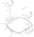
- FIG. 1is a perspective view of an adjustable resistance exercise device, consistent with an embodiment of the present disclosure.
- FIGS. 2A and 2Bare side views of the adjustable resistance exercise device shown in FIG. 1 with the handles in seated and partially retracted positions, respectively.
- FIG. 3is a top cross-sectional view of the adjustable resistance exercise device taken along line 3 - 3 in FIG. 2A .
- FIG. 4is a side cross-sectional view of the adjustable resistance exercise device taken along line 4 - 4 in FIG. 2B .
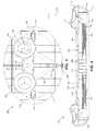
- FIG. 5is an exploded view of the adjustable resistance exercise device shown in FIG. 1 .
- FIG. 6is an exploded view of one embodiment of the adjustable resistance and retraction mechanism used to provide independent resistance forces and retraction forces on the cables in the adjustable resistance exercise device.
- FIG. 7is a cross-sectional perspective view of a resistance wheel selectively engaged with a cable receiving spool using a locking cam gear mechanism, consistent with an embodiment.
- FIG. 8is an exploded cross-sectional perspective view of the locking cam gear mechanism shown in FIG. 7 .
- FIG. 9is a top view of the locking cam gear mechanism shown in FIGS. 7 and 8 .
- FIG. 10is an exploded perspective view of another embodiment of the adjustable resistance exercise device.
- FIG. 11is a cross-sectional view of the adjustable resistance exercise device shown in FIG. 10 .
- FIG. 12is an exploded view of another embodiment of an adjustable resistance and retraction mechanism.
- FIG. 13is a perspective view of the adjustable resistance and retraction mechanism shown in FIG. 12 .
- FIG. 14is an exploded view of an adjustment mechanism in the adjustable resistance and retraction mechanism shown in FIG. 13 .
- FIG. 15is a bottom view of the adjustment mechanism in the adjustable resistance and retraction mechanism shown in FIG. 13 .
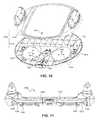
- FIG. 16is an exploded perspective view of another embodiment of the adjustable resistance exercise device.
- FIG. 17is a cross-sectional view of the adjustable resistance exercise device shown in FIG. 16 .
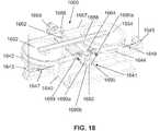
- FIG. 18is a perspective view of the adjustable resistance and retraction mechanism.
- FIG. 19is another perspective view of the adjustable resistance and retraction mechanism of FIG. 18 .
- FIG. 20is a cross-sectional view of an embodiment of a handle that may be used in an adjustable resistance exercise device.
- FIG. 21is a perspective view of the handle shown in FIG. 20 .
- FIG. 22is a front view of an embodiment of a handle that may be used in an adjustable resistance exercise device.
- FIG. 23is a perspective view of the handle shown in FIG. 22 with the housing and handle grip removed.
- a resistance exercise devicein general, enables resistance training by using one or more retractable cables that provide resistance to the user when the user pulls on the cable(s).
- the resistance exercise deviceprovides a retraction force to retract the cable(s), which is independent of a resistance force applied to the cable(s).
- the resistance exercise devicemay thus allow adjustment of the resistance force without affecting the retraction force.
- the resistance exercise deviceincludes a portable exercise platform with two independently functioning cables; however, the concept of providing a retraction force independent of a resistance force may be used in other types of resistance exercise devices.
- an embodiment of an adjustable resistance exercise device 100generally includes a platform 110 and handles 122 , 124 coupled to cables 132 , 134 that extend from and retract into the platform 110 .
- the cables 132 , 134may be understood to include one or more wires, ropes, belts or resistance bands. In one embodiment, where more than one wire, rope, belt or band may be present the wire, rope, belt or band may be bonded, twisted or braided together.
- the cablemay be formed from reinforced cord, climbing rope, textured belt, etc. Furthermore, the cable may be formed from metals or metal alloys, polymer materials including synthetic rubber or synthetic fibers, natural fibers, or combinations thereof.
- the platform 110may generally include a housing 111 enclosing a resistance and retraction mechanism (not shown) for providing the resistance and retraction forces to the cables 132 , 134 , as will be described in greater detail below.
- the platform 110may also include handle engaging regions 112 , 114 that receive the handles 122 , 124 and a surface 116 , such as a flat surface, that receives a part of the user's body, such as the user's feet, to stabilize the platform 110 as the user grips the handles 122 , 124 and pulls the cables 132 , 134 from the platform 110 .
- the surface 116may include a rubber mat and the bottom of the housing 111 may include one or more rubber feet (not shown).
- the illustrated embodimenthas a platform 110 and handles 122 , 124 of a particular shape, various other shapes and configurations may be used.
- the platform 110may be shaped or designed to receive other parts of the user's body (e.g., the knees, back, buttocks) and/or the handles 122 , 124 may be shaped to be engaged by other parts of the user's body (e.g., the feet).
- the platform 110is shown as a portable platform, the platform may be integrated in an exercise device that is fixed or the cables 132 , 134 may extend from an exercise device without a platform.
- An exercise device implementing the concepts described hereinmay also include only one cable and handle or more than two cables and handles.
- FIGS. 2A and 2Billustrate a handle 124 in a retracted position and partially extended position, respectively.
- the handle 124engages the handle engaging region 114 .
- the handle 124may be seated in the handle engaging region 114 .
- the handle 124is removed from the handle engaging region 114 and a portion of the cable 134 extends from the platform 110 .
- a resistance force F RSis applied to the cable 134 to resist muscular contraction of the user pulling the cable 134 via the handle 124 .
- a retraction force F RTis applied to the cable 134 to cause retraction of the cable 134 into the platform 110 .
- the retraction force F RTis applied independently of the resistance force F RS in that the resistance force F RS is not applied when the cable 134 is retracted.
- the illustrated embodiment of the exercise device 100generally includes a support frame 140 and cable receiving spools 142 , 144 rotatably coupled to the support frame 140 and coupled to the respective cables 132 , 134 (only cable 134 is shown).
- the cable receiving spools 142 , 144each rotate independently in a winding direction (as indicated by arrow 106 ) when the respective cable is being retracted and in an unwinding direction (as indicated by arrow 108 ) when the respective cable is being extended.
- Pulleys 143 , 145may also be rotatably mounted to the support frame 140 to receive and guide the respective cables 132 , 134 to the respective cable receiving spools 142 , 144 .
- the pulleys 143 , 145may each have an axis of rotation that is generally orthogonal to an axis of rotation of the respective cable receiving spools 142 , 144 such that the spools 142 , 144 can lie flat within the housing 111 of the platform 110 with the cables 132 , 134 extending generally orthogonally from the platform 110 .
- the housing 111 of the platform 110may include first and second housing portions 111 a , 111 b .
- One of the housing portions 111 a(e.g., an upper housing portion) may include the surface 116 and the handle engaging regions 112 , 114 .
- One of the housing portions 111 b(e.g., a lower housing portion) may be designed to receive and secure the frame 140 .
- One or both of the housing portions 111 a , 111 bmay include reinforcing structures 113 , such as walls, that reinforce the housing 111 to withstand the forces applied to the platform 110 when using the exercise device 100 .
- the frame 140is shown separately from the housing portions 111 a , 111 b , the frame 140 may be integrated with or one-piece with the either of the housing portions 111 a , 111 b.
- the exercise device 100may include a resistance and retraction mechanism 150 that is operably coupled to the cable receiving spools 142 , 144 to apply the resistance forces and to apply the retraction forces independent of the resistance forces.
- the resistance and retraction mechanism 150applies the resistance force to resist rotation of the cable receiving spools 142 , 144 in the unwinding direction.
- the resistance forceis then transferred to the respective cables 132 , 134 to resist extension of the cables 132 , 134 toward the extended position when the respective cable receiving spools are rotating in the unwinding direction.
- the resistance and retraction mechanism 150applies the retraction force to cause the cable receiving spools 142 , 144 to rotate in the winding direction.
- the retraction forceis then transferred to the respective cables 132 , 134 to retract the cables toward the retracted position when the respective cable receiving spools are rotating in the winding direction.
- the exemplary embodiment of the resistance and retraction mechanism 150applies the resistance forces only when the respective cable receiving spools 142 , 144 are rotating in the unwinding direction.
- the resistance and retraction mechanism 150may provide an adjustable resistance force, as described in greater detail below, such that the resistance force may be changed without changing the retraction force.
- an embodiment of the resistance and retraction mechanism 150may include resistance wheels 152 , 154 rotatably coupled to the support frame 140 and one or more rotation resistance members 156 that engage the resistance wheels 152 , 154 to resist rotation of the resistance wheels 152 , 154 .
- the resistance wheels 152 , 154may be selectively engaged with the respective cable receiving spools 142 , 144 such that the cable receiving spools 142 , 144 cause the respective resistance wheels 152 , 154 to rotate when the respective cable receiving spools 142 , 144 rotate in the unwinding direction (i.e., engaged) and the respective cable receiving spools 142 , 144 rotate independently in the winding direction (i.e., disengaged).
- resistance forcesare applied by the resistance wheels 152 , 154 only when the cable receiving spools 142 , 144 are rotating in the unwinding direction, as will be described in greater detail below.
- the rotation resistance member 156is a resistance belt 157 wrapped around both resistance wheels 152 , 154 and engaging at least a portion of an annular surface of the resistance wheels 152 , 154 .
- the resistance forceis the friction force that results from rotating the resistance wheels 152 , 154 against the resistance belt 157 .
- Guides 153 , 155may be mounted to the frame 140 and may guide the rotation resistance belt 157 around a desired portion of the resistance wheels 152 , 154 .
- the amount of surface area of the resistance belt 157 in contact with the annular surface of the resistance wheels 152 , 154 (and thus the friction force)depends on the location of the guides 153 , 155 relative to the resistance wheels 152 , 154 .
- the amount of surface area of the resistance belt 157 in contact with the resistance wheels 152 , 154also affects the adjustability of the resistance force by changing the tension in the resistance belt 157 , as described below.
- the guides 153 , 155are located such that the resistance belt 157 contacts between about 1 ⁇ 2 and 3 ⁇ 4 of the circumference of the resistance wheels 152 , 154 .
- the resistance mechanismmay be capable of providing a total of 140 lbs. of resistance force (e.g., 70 lbs. on each side).
- the rotation resistance belt 157may be made of woven nylon or another suitable material that provides a similar coefficient of friction and that is sufficiently durable when subjected to the friction, as well as stainless steel or other metals or metal alloys.
- the surface area of the resistance belt 157 in contact with the resistance wheels 152 , 154also depends on the width of the resistance belt 157 .
- the resistance belt 157may have a width in a range of about 1 ⁇ 2 inches to 3 inches.
- the rotation resistance member(s) 156may also include separate resistance belts wrapped around each of the resistance wheels 152 , 154 or may include other friction generating members that contact the resistance wheels 152 , 154 to cause a friction force when the resistance wheels are rotated.
- the resistance and retraction mechanism 150may further include a resistance force adjustment mechanism 160 that adjusts the resistance force, for example, by adjusting the friction force generated by the resistance wheels 152 , 154 rotating against the resistance member(s) 156 .
- the resistance force adjustment mechanism 160includes a threaded adjustment rod 162 threadably engaged with a sliding block 164 , or similar structure, coupled to the resistance belt 157 . Turning the threaded adjustment rod 162 (e.g., using an adjustment knob 168 ) causes the block 164 to move and changes the tension in the resistance belt 157 , which changes the force applied by the resistance belt 157 against the resistance wheels 152 , 154 and the resulting friction force.
- a movement of the threaded adjustment rod 162 of about 1 inchallows an adjustment from 5 lbs. to 70 lbs. of resistance force applied by each of the resistance wheels 152 , 154 .
- Other resistance force adjusting mechanisms capable of increasing or decreasing the friction forcemay also be used.
- the exemplary embodiment of the resistance and retraction mechanism 150also includes radial springs 158 (only one is shown in FIG. 6 ) that engage the cable receiving spools 142 , 144 to apply the retraction forces.
- the radial spring 158is wound when the respective cable receiving spool 142 are rotated in the unwinding direction by the respective cable 132 moving toward the extended position (i.e., when the user pulls on the cables).
- the force stored in the wound radial spring 158provides the retraction force that causes the cable receiving spool 142 to rotate in the winding direction, thereby winding and retracting the cable 132 .
- the resistance and retraction mechanism 150may also be used in the resistance and retraction mechanism 150 to generate the retraction forces. Because the resistance wheel 152 is disengaged from the cable receiving spool 142 during rotation in the winding direction, the radial spring 158 generates the retraction force independent of the resistance force generated by the resistance wheel 152 .
- a locking cam gear mechanism 170may be used to selectively engage the cable receiving spools 142 , 144 and the resistance wheels 152 , 154 .
- the locking cam gear mechanism 170is fixedly engaged to the resistance wheel 152 , for example, using one or more pins 171 , and is selectively engaged to the cable receiving spool 142 .
- the cable receiving spool 142includes a recessed region formed by an annular surface 141 and the locking cam gear mechanism 170 is received in the recessed region.
- An embodiment of the locking cam gear mechanism 170includes a cam gear 172 and one or more lock bearings 173 that engage the cam gear 172 .
- the cam gear 172includes one or more cam surfaces 175 and bearing surfaces 177 that form one or more teeth 176 .
- the lock bearings 173are located between the teeth 176 such that the cam surface(s) 173 engage the lock bearings 173 when the cam gear 172 rotates in one direction (as indicated by arrow 106 ) and engage the bearing surface(s) 177 when the cam gear 172 rotates in the opposite direction (as indicated by arrow 108 ).
- the cam surface 175forms an acute angle relative to the annular surface 141 such that the lock bearing 173 wedges between the cam surface 175 and the annular surface 141 when rotating in the direction of arrow 106 .
- the bearing surface 177forms a generally perpendicular angle relative to the annular surface 141 such that the lock bearing 173 rolls against the annular surface 141 when pushed by the bearing surface 177 .
- the cam gear 172 and the lock bearings 173lock against the annular surface 141 of the cable receiving spool 142 when rotating in the direction of arrow 106 (i.e., the unwinding direction) and rotate freely with respect to the annular surface 141 when rotating in the direction of arrow 108 (i.e., the winding direction).
- One or more bearings 179such as thrust bearings, may be used to facilitate rotation of the cable receiving spool 142 and the locking cam gear mechanism 170 .
- the locking cam gear 172may also be fixedly secured to the resistance wheel 152 using other structures or by forming the cam gear 172 as one piece with the resistance wheel 152 .
- the locking cam gear mechanism 170may be fixedly engaged to the cable receiving spool 142 and selectively engaged with the resistance wheel 152 .
- the lock bearings 173are shown as rods, they may also be balls or similar structures that will move with the cam gear 172 in one direction of rotation and lock with the cam gear 172 in the other direction of rotation. Further embodiments may use other types of mechanisms, such as ratchet mechanisms, that provide selective engagement in different directions of rotation.
- the adjustable resistance exercise device 1000includes cable receiving spools 1042 , 1044 and a resistance and retraction mechanism 1050 including resistance wheels 1052 , 1054 located closer to an adjustment mechanism 1060 .
- the adjustable resistance exercise device 1000also includes cable pulleys 1043 , 1045 that guide cables 1032 , 1034 to and from the cable receiving spools 1042 , 1044 .
- the cable receiving spools 1042 , 1044rotate in winding and unwinding directions that are opposite the winding and unwinding directions in the embodiment described above.
- the cable receiving spools 1042 , 1044 , pulleys 1043 , 1045 and resistance and retraction mechanism 1050are mounted to a frame 1040 and provided within a platform 1010 , for example, as described above.
- the adjustment mechanism 1060includes a gauge 1061 that allows a user to gauge the resistance adjustment.
- the gauge 1061may be visible through an aperture 1017 in the platform 1010 .
- the gauge 1061may be calibrated to indicate the approximate resistance (e.g., in pounds) applied to one or both sides of the exercise device 1000 .
- the adjustment mechanism 1060also includes a threaded adjustment rod 1062 that threadably engages a slider 1064 , which is coupled to a tensioning wheel 1066 or similar structure.
- the tensioning wheel 1066receives a resistance belt 1057 and moves the resistance belt 1057 to adjust the tension thereof and the resistance applied to the resistance wheels 1052 , 1054 .
- the gauge 1061may include a dial 1063 located in the aperture 1017 of the platform 1010 and a pointer fixed to the slider 1064 and moving relative to the dial 1063 .
- the dial 1063may include one or more markings or indicia to indicate a relative position of the slider 1064 and thus the relative resistance applied by the resistance belt 1057 .
- the slider 1064may be received in a guide portion 1041 extending from the frame 1040 , and a bolt 1065 or similar structure may extend from the slider 1064 to engage and move the tensioning wheel 1066 .
- a belt securing member 1067may secure the resistance belt 1057 against a portion 1069 of the tensioning wheel 1066 to prevent the resistance belt 1057 from sliding when the resistance wheels 1052 , 1054 rotate against the resistance belt 1057 .
- a tension belt 1357is coupled to a tensioning wheel 1366 or similar structure using hardware such as a nut 1367 and threaded fastener 1368 (e.g., a bolt or socket head cap screw).
- the nut 1367is held captive in a slot 1369 in the tensioning wheel 1366 and the threaded fastener 1368 extends through the belt 1357 and into the slot 1369 to threadably engage the nut 1367 .
- the adjustment mechanism 1360also includes a slider 1364 coupled to the tensioning wheel 1366 as described above (see FIG. 15 ).
- the slider 1364may be made of a plastic material with a steel insert 1361 forming the threaded portion that receives the threaded rod.
- the slider 1364may also be hollow with ribs 1363 ( FIG. 15 ) or may be solid.
- the cable pulleys 1343 , 1345may be secured to the frame 1340 using fasteners, such as socket head cap screws, which may pass through the frame 1340 and the bottom of the platform.
- the adjustable resistance exercise device 1600includes cable receiving spools 1642 , 1644 and a resistance and retraction mechanism 1650 including resistance wheels 1652 , 1654 located close to or on either side of a tension adjustment mechanism 1660 .
- the adjustable resistance exercise device 1600also includes cable pulleys 1643 , 1645 that guide cables 1632 , 1634 to and from the cable receiving spools 1642 , 1644 .
- one or more eyelets 1647 , 1649FIG.
- the cable pulleys 1643 , 1645 and cable receiving spools 1642 , 1644may also be provided between the cable pulleys 1643 , 1645 and cable receiving spools 1642 , 1644 to help guide the cables 1632 , 1634 and prevent the cables from becoming dislodged from either the cable pulleys 1643 , 1645 or cable receiving spools 1642 , 1644 .
- the cable receiving spools 1642 , 1644 , pulleys 1643 , 1645 and resistance and retraction mechanism 1650are mounted to a frame 1640 and provided within a platform 1610 , for example, as described above.
- the frame 1640may be formed of a single piece or a number of pieces held together by mechanical fasteners such as nuts and bolts or rivets.
- a support member 1680may be provided, extending between the resistance wheels 1652 , 1654 .
- the support member 1680may include a channel shaped cross-section, which may provide a recess to accommodate the fasteners, retain the resistance wheels 1652 , 1654 in place and/or provide support for the platform 1610 .
- Additional support members 1682 , 1683 , 1684may be provided in the housing 1611 , either on the upper or lower portions of the housing 1611 a , 1611 b , to prevent or reduce flexion of the platform 1610 or housing 1611 .
- Such support membersmay include one or more bosses 1682 , blocks 1683 , ribs 1684 , as well as other support members. It may be appreciated that the support bar and or support members may exhibit other geometries as well, such as rectangular, oval, square, etc.
- the support members including the bosses, blocks, ribs, etc.may be present alone or in combination.
- the adjustment mechanism 1660also includes a threaded adjustment rod 1662 .
- the threaded adjustment rod 1662may include at least two sets of threads that run opposing directions. Stated another way, the threads may run in a right handed direction relative to each end 1686 a , 1686 b of the threaded adjustment rod 1662 and may meet at or near the middle 1688 of the adjustment rod 1662 .
- the threadsmay begin at a distance from each end 1686 a , 1686 b of the adjustment rod 1662 (at the same or different locations between each end 1686 a , 1686 b and the middle 1688 ), providing for other features that may be located proximal to the ends 1686 a , 1686 b of the adjustment rod 1662 .
- the threaded adjustment rodmay threadably engage at least two sliding blocks 1664 , 1666 which may ride in a guide portion 1641 that may include a tension adjustment track 1690 .
- the tension adjustment track 1690may prevent the rotation of the sliding blocks 1664 , 1666 relative to the frame 1640 and the sliding blocks 1664 , 1666 may move in opposing directions along the tension adjustment track 1690 when the threaded adjustment rod 1662 is rotated.
- the tension adjustment track 1690may be a unitary track or may be formed from an upper adjustment track 1690 a and a lower adjustment track 1690 b . In some embodiments, the tension adjustment track 1690 may be integrated into the support frame 1640 .
- the tension adjustment track 1690may define openings 1692 , 1694 on either side of the track 1690 to accommodate the threaded adjustment rod 1662 .
- the threaded adjustment rodmay also include a lip 1696 , 1698 ( FIG. 19 ) formed around at least a portion of the threaded adjustment rod 1662 located at or near the end portions 1686 a , 1686 b of the threaded adjustment rod 1662 to position the threaded adjustment rod 1662 within the tension adjustment track 1690 .
- the resistance belt 1657may be affixed to each sliding blocks 1664 , 1666 and motion of the sliding blocks 1664 , 1666 along tension adjustment track 1690 moves the resistance belt 1657 to further engage or disengage the resistance belt 1657 with the resistance wheels 1652 , 1654 .
- the resistance beltmay be formed from stainless steel, which may reduce fatigue and prevent stretching or deformation of the belt over time.
- the resistance beltmay also be formed from a band composed of fibers including synthetic or natural fibers, or a polymeric sheet, or a metal or metal alloys, as well as combinations thereof.
- Engagement or disengagement of the resistance belt 1657adjusts the resistance force applied to the resistance wheels 1652 , 1654 .
- movement of the sliding blocks 1664 , 1666 of about 1 ⁇ 2 inchallows an adjustment from 5 lbs. to 70 lbs. of resistance force applied by each of the resistance wheels.
- motion of the sliding blocks 1664 , 1666 towards each otherincreases contact area of the resistance belt 1657 on the resistance wheels 1652 , 1654 thereby increasing the resistance force applied to the resistance wheels 1652 , 1654 .
- motion of the sliding blocks 1664 , 1666 away from each otherreduces the contact area of the resistance belt 1657 on the resistance wheels 1652 , 1654 thereby decreasing the resistance force applied to the resistance wheels 1652 , 1654 .
- the resistance beltmay be affixed to one of the sliding blocks 1664 by tension adjustment springs 1693 , 1695 ( FIG. 19 ). It may be appreciated that in some embodiments, the resistance belt may be affixed to both sliding blocks 1664 , 1666 with tension adjustments springs 1693 , 1695 . It may further be appreciated that the tension adjustment springs 1693 , 1695 may aid in assembly of the device and/or may provide some amount of pre-load or tension to the resistance wheels 1652 , 1654 , which may prevent slack from forming in the resistance belt 1657 .
- the tension adjustment springs 1693 , 1695may be affixed to the resistance belt 1657 by a mechanical fastener such as a bolt 1697 and nut 1699 or by a rivet.
- a handle 2020may include a strength member 2021 and a housing 2023 that encloses at least a portion of the strength member 2021 .
- the strength member 2021is coupled to a cable 2030 , for example, through a cable coupling portion 2031 extending through a bottom of the handle 2020 .
- the strength member 2021may be made of a metal or other suitable material capable of withstanding the forces applied to the handle 2020 during use.
- the housing 2023may be made of a plastic or other suitable material and may include ribs 2027 that provide reinforcement.
- a handle grip 2025may be rotatably mounted on the strength member 2021 such that the grip 2025 rotates when the user pulls on the handle 2020 .
- a handle 2220may include a housing 2223 and a handle grip 2225 covering at least a portion of the housing 2223 .
- At least one strap 2226may be affixed to the housing 2223 by clips 2227 , 2229 , to which the strap 2226 may be adhered or otherwise affixed.
- the strap 2226may be formed from natural or synthetic fibers woven together to form a belt, formed from a polymeric sheet or tube, or formed from coated wires, reinforced cords, etc.
- the clips 2227 , 2229may be affixed to the housing 2223 by bolts 2231 , 2233 , which may pass through the clips 2227 , 2229 and threadably engage nuts 2235 , 2237 affixed to the housing 2223 .
- the clips 2227 , 2229may be held to the housing 2223 by other mechanical fasteners such as by pins, which may form an interference fit with the housing, or by stakes welded to the housing.
- the bolts 2231 , 2233 or other fastenersmay include a rounded head portion as illustrated, however other geometries may be used as well.
- the strap 2226may be affixed to the cable 2232 (representing, for example, cables 1632 , 1634 of FIGS. 16 through 19 or cables 132 , 134 illustrated in FIGS. 1 through 9 , etc.) by a handle fastener 2228 .
- the handle fastener 2228may define a slot 2230 through which the strap 2226 may pass.
- the strap 2226may move freely back and forth through the slot 2230 or may be affixed once positioned in the slot 2230 by staking, welding, or by a mechanical fastener such as a screw.
- the handle fastener 2228may be affixed to the cable 2232 .
- the handle fastener 2228may be molded directly over and onto the cable 2232 , or the cable 2232 may be threaded through the fastener 2228 and locked into place by a knot, clip or other mechanical fastener or affixed by application of an adhesive.
- the adjustable exercise deviceuses a resistance and retraction mechanism that provides a retraction force (when retracting a cable) independent of a resistance force (when extending a cable).
- a resistance and retraction mechanismthat provides a retraction force (when retracting a cable) independent of a resistance force (when extending a cable).
- the resistance forcecan be adjusted without changing the retraction force.
- an adjustable resistance exercise deviceincludes a support frame, at least one cable receiving spool rotatably coupled to the support frame, and at least one cable coupled to the cable receiving spool, wherein a length of the cable is coiled around the cable receiving spool in a retracted position and wherein the length of the cable extends from the cable receiving spool in an extended position, wherein the cable receiving spool is rotatable in a winding direction when the cable is being retracted toward the retracted position, and wherein the cable receiving spool is rotatable in an unwinding direction when the cable is being extended toward the extended position.
- the adjustable resistance exercise devicealso includes at least one adjustable resistance and retraction mechanism operably coupled to the cable receiving spool to apply an adjustable resistance force to the cable receiving spool and to apply a retraction force to the cable receiving spool independent of the adjustable resistance force, wherein the resistance force resists rotation of the cable receiving spool in the unwinding direction to resist extension of the cable toward the extended position when the cable receiving spool is rotating in the unwinding direction, wherein the resistance force is applied only when the cable receiving spool is rotating in the unwinding direction, and wherein the retraction force causes the cable receiving spool to rotate in the winding direction to retract the cable toward the retracted position when the cable receiving spool is rotating in the winding direction.
- the at least one adjustable resistance and retraction mechanismincludes a rotation resistance member operably coupled to the cable receiving spool to apply the adjustable resistance force to the cable receiving spool and a tension adjustment member operably coupled to the resistance member to adjust the resistance force applied to the cable receiving spool.
- a resistance exercise deviceincludes a support frame, at least one resistance wheel rotatably coupled to the support frame, at least one cable receiving spool rotatably coupled to the support frame and selectively engaged with the resistance wheel such that rotation of the cable receiving spool in an unwinding direction causes the resistance wheel to rotate and rotation of the cable receiving spool in a winding direction is independent of the resistance wheel and at least one cable coupled to the cable receiving spool, wherein a length of the cable is coiled around the cable receiving spool in a retracted position and wherein the length of the cable extends from the cable receiving spool in an extended position.
- the resistance exercise devicealso includes at least one resistance member engaging the resistance wheel to resist rotation of the resistance wheel in the unwinding direction such that the cable resists extension toward the extended position and at least one tension adjusting member operably coupled to the resistance member such that the tension adjusting member increases or decreases the engagement of the resistance member with the resistance wheel.
- an adjustable resistance exercise deviceincludes a support frame, first and second cable receiving spools rotatably coupled to the support frame and first and second cables coupled to the cable receiving spools, respectively, wherein a length of each of the cables is coiled around the respective cable receiving spools in a retracted position and wherein the lengths of each of the cables extend from the respective cable receiving spools in an extended position.
- each of the cable receiving spoolsis rotatable in a winding direction when the respective cable is being retracted toward the retracted position, and each of the cable receiving spools is rotatable in an unwinding direction when the respective cable is being extended toward the extended position.
- the adjustable resistance exercise devicealso includes at least one adjustable resistance and retraction mechanism including first and second resistance wheels rotatably coupled to the support frame and selectively engaged with the respective first and second cable receiving spools such that the cable receiving spools and the resistance wheels are engaged when the respective cable receiving spools rotate in the unwinding direction to apply adjustable resistance forces to the cables and the cable receiving spools and the resistance wheels are disengaged when the respective cable receiving spools rotate in the winding direction.
- the adjustable resistance and retraction mechanismalso includes at least one rotation resistance member engaging the first and second resistance wheels, respectively, to resist rotation of the resistance wheels, and a tension adjustment member operably coupled to the rotation resistance member to adjust the degree of engagement between the resistance member and the first and second resistance wheels.
Landscapes
- Health & Medical Sciences (AREA)
- Orthopedic Medicine & Surgery (AREA)
- General Health & Medical Sciences (AREA)
- Physical Education & Sports Medicine (AREA)
- Life Sciences & Earth Sciences (AREA)
- Biophysics (AREA)
- Rehabilitation Tools (AREA)
Abstract
Description
Claims (19)
Priority Applications (1)
| Application Number | Priority Date | Filing Date | Title |
|---|---|---|---|
| US12/605,612US7942793B2 (en) | 2009-02-12 | 2009-10-26 | Adjustable resistance exercise device |
Applications Claiming Priority (2)
| Application Number | Priority Date | Filing Date | Title |
|---|---|---|---|
| US12/369,917US7909745B2 (en) | 2009-02-12 | 2009-02-12 | Adjustable resistance exercise device |
| US12/605,612US7942793B2 (en) | 2009-02-12 | 2009-10-26 | Adjustable resistance exercise device |
Related Parent Applications (1)
| Application Number | Title | Priority Date | Filing Date |
|---|---|---|---|
| US12/369,917Continuation-In-PartUS7909745B2 (en) | 2009-02-12 | 2009-02-12 | Adjustable resistance exercise device |
Publications (2)
| Publication Number | Publication Date |
|---|---|
| US20100204024A1 US20100204024A1 (en) | 2010-08-12 |
| US7942793B2true US7942793B2 (en) | 2011-05-17 |
Family
ID=42540904
Family Applications (1)
| Application Number | Title | Priority Date | Filing Date |
|---|---|---|---|
| US12/605,612Expired - Fee RelatedUS7942793B2 (en) | 2009-02-12 | 2009-10-26 | Adjustable resistance exercise device |
Country Status (1)
| Country | Link |
|---|---|
| US (1) | US7942793B2 (en) |
Cited By (32)
| Publication number | Priority date | Publication date | Assignee | Title |
|---|---|---|---|---|
| US20110207580A1 (en)* | 2009-08-26 | 2011-08-25 | Ken Wright | Exercise device |
| US20120245004A1 (en)* | 2011-03-25 | 2012-09-27 | Jon Bremer | Personal stretching device |
| WO2013033757A1 (en)* | 2011-09-05 | 2013-03-14 | Powell Stewart William | Exercise device and method of use |
| US20130231228A1 (en)* | 2012-03-02 | 2013-09-05 | Maurice Wyatt | Multi-functional exercise apparatus |
| US20140155232A1 (en)* | 2012-12-05 | 2014-06-05 | Edward Anthony Wolan | Portable resistance band exercise machine |
| US8876666B1 (en) | 2012-03-20 | 2014-11-04 | Brent M. Palmer | Exercising assembly |
| US9199114B1 (en) | 2013-11-25 | 2015-12-01 | Vincent Santoro | Harness with upper body exerciser |
| US20150352396A1 (en)* | 2014-06-09 | 2015-12-10 | Icon Health & Fitness, Inc. | Cable System Incorporated Into a Treadmill |
| US20160082306A1 (en)* | 2014-09-18 | 2016-03-24 | Otis Williams | Exercise System |
| US9387354B1 (en) | 2015-08-04 | 2016-07-12 | Vincent Santoro | Harness with upper body exerciser |
| US9463347B2 (en)* | 2008-11-03 | 2016-10-11 | David Kristiansen | Ergonomic pull handle and associated exercise methods |
| USD776767S1 (en) | 2015-01-26 | 2017-01-17 | Erica Gay Randleman | Exercise platform |
| US10188890B2 (en) | 2013-12-26 | 2019-01-29 | Icon Health & Fitness, Inc. | Magnetic resistance mechanism in a cable machine |
| US20190060695A1 (en)* | 2017-03-23 | 2019-02-28 | Evan Weisz | Exercise case with an adjustable resistance band system |
| US10252109B2 (en) | 2016-05-13 | 2019-04-09 | Icon Health & Fitness, Inc. | Weight platform treadmill |
| US10279212B2 (en) | 2013-03-14 | 2019-05-07 | Icon Health & Fitness, Inc. | Strength training apparatus with flywheel and related methods |
| US10293211B2 (en) | 2016-03-18 | 2019-05-21 | Icon Health & Fitness, Inc. | Coordinated weight selection |
| US10343006B2 (en) | 2016-06-23 | 2019-07-09 | Spiraflex Inc. | Exercise device and preloaded resistance pack |
| US10441840B2 (en) | 2016-03-18 | 2019-10-15 | Icon Health & Fitness, Inc. | Collapsible strength exercise machine |
| US10449416B2 (en) | 2015-08-26 | 2019-10-22 | Icon Health & Fitness, Inc. | Strength exercise mechanisms |
| US10569121B2 (en) | 2016-12-05 | 2020-02-25 | Icon Health & Fitness, Inc. | Pull cable resistance mechanism in a treadmill |
| US10661114B2 (en) | 2016-11-01 | 2020-05-26 | Icon Health & Fitness, Inc. | Body weight lift mechanism on treadmill |
| US10668320B2 (en) | 2016-12-05 | 2020-06-02 | Icon Health & Fitness, Inc. | Tread belt locking mechanism |
| US10940360B2 (en) | 2015-08-26 | 2021-03-09 | Icon Health & Fitness, Inc. | Strength exercise mechanisms |
| TWI723863B (en)* | 2020-01-21 | 2021-04-01 | 肯尼實業有限公司 | Portable fitness device |
| US10981032B2 (en) | 2018-12-10 | 2021-04-20 | Erica Randleman | Mobile exercise platform |
| USD930093S1 (en)* | 2020-07-23 | 2021-09-07 | Dongchun Lyu | Portable fitness platform |
| US11298577B2 (en) | 2019-02-11 | 2022-04-12 | Ifit Inc. | Cable and power rack exercise machine |
| US11338167B2 (en) | 2019-12-02 | 2022-05-24 | Richard Gonsalves Balelo, JR. | Exercise device and method of use |
| USD973154S1 (en)* | 2020-09-14 | 2022-12-20 | Guangzhou Rantion Technology Co., Ltd | Exercise board |
| US11872438B2 (en) | 2021-04-14 | 2024-01-16 | John Hubble | Exercise device incorporating gyroscopic initiated dynamic resistance |
| US20250144462A1 (en)* | 2023-11-07 | 2025-05-08 | Paul S. Pflum | Compact exercise apparatus |
Families Citing this family (24)
| Publication number | Priority date | Publication date | Assignee | Title |
|---|---|---|---|---|
| USD682374S1 (en)* | 2010-09-11 | 2013-05-14 | William T. Wilkinson | Exercise resistance device |
| US8597164B2 (en)* | 2011-09-10 | 2013-12-03 | Spiraflex, Inc. | Personal exercise device |
| ITMI20120337A1 (en)* | 2012-03-05 | 2013-09-06 | Milano Politecnico | TRAINING DEVICE WITH VARIABLE RESISTANCE |
| ES1078354Y (en)* | 2012-12-07 | 2013-04-04 | Saez Juan Moya | BANK OF FOLDING STRUCTURE ROLLERS |
| US9409047B2 (en)* | 2013-02-14 | 2016-08-09 | Vitalika Inc | Exercise apparatus |
| GB201314362D0 (en)* | 2013-08-11 | 2013-09-25 | Bowles Robert G | Exercise devise |
| US10436545B2 (en) | 2015-07-20 | 2019-10-08 | AccuBow LLC | Adjustable archery training bow |
| US10281232B2 (en) | 2015-07-20 | 2019-05-07 | AccuBow LLC | Virtual reality archery training system |
| ES2588949B2 (en)* | 2016-07-29 | 2017-04-24 | Universidad De Jaén | Muscle training device |
| US10556143B2 (en) | 2017-01-27 | 2020-02-11 | Keph SHERIN | Constant force resistance cable retractor |
| IT201700065174A1 (en)* | 2017-06-13 | 2018-12-13 | Simon Sparber | Additional handle for fitness and similar equipment and / or tools |
| USD842398S1 (en)* | 2017-08-05 | 2019-03-05 | Zhejiang Raytheon Technology Co., Ltd. | Body shaping equipment with cord |
| US10857408B2 (en) | 2017-12-11 | 2020-12-08 | Fariba Miri-Ghomizadeh | Body roller sleeve |
| JP1708263S (en)* | 2021-03-23 | 2022-02-24 | Training equipment | |
| CN112915460B (en)* | 2021-04-16 | 2024-06-28 | 湖州艾先特电子科技有限公司 | Adjustable pulling force detection module and contain detection device of this module |
| US11400332B1 (en)* | 2021-05-11 | 2022-08-02 | Luke Alford | Resistance band apparatus, method, and system |
| TWI758189B (en)* | 2021-05-17 | 2022-03-11 | 昌祐科技國際股份有限公司 | Rally fitness equipment |
| IL284597A (en)* | 2021-07-04 | 2023-02-01 | Tayar Eliahu | Fitness device |
| WO2023212392A1 (en) | 2022-04-30 | 2023-11-02 | AccuBow, LLC | Ar/vr crossbow system |
| USD1088147S1 (en)* | 2023-07-26 | 2025-08-12 | Xiamen Renhe Sports Equipment Co., Ltd. | Exercise platform |
| US20250090893A1 (en)* | 2023-09-14 | 2025-03-20 | I-Tech Usa, Inc. | Electric full body fitness equipment |
| CN116942234B (en)* | 2023-09-20 | 2023-12-19 | 泓欣科创(北京)科技有限公司 | Tension controller for automatic wire winding |
| USD1095706S1 (en)* | 2024-01-25 | 2025-09-30 | Hefei Xuanjie Fitness Equipment Technology Co., Ltd. | Resistance band foot plate |
| USD1088151S1 (en)* | 2025-03-21 | 2025-08-12 | Dong Sy Nguyen | Resistance band foot plate |
Citations (45)
| Publication number | Priority date | Publication date | Assignee | Title |
|---|---|---|---|---|
| US2959414A (en) | 1958-06-23 | 1960-11-08 | Saltz Bernard | Exerciser |
| US3610617A (en) | 1967-07-24 | 1971-10-05 | Apollo Distributors Ltd | Exercising device |
| US3764132A (en)* | 1972-05-18 | 1973-10-09 | Adrian Poppel M | Friction type exercising apparatus |
| US4138106A (en)* | 1977-08-15 | 1979-02-06 | Micro Circuits Company | Weight training apparatus |
| US4235439A (en) | 1979-05-21 | 1980-11-25 | Super Stretch Co., Ltd. | Friction type exercising device |
| US4403773A (en) | 1980-03-10 | 1983-09-13 | Swann David T | Exercising apparatus |
| US4625961A (en) | 1982-12-30 | 1986-12-02 | Brand Dieter C H | Transportable home energy training device and sprocket |
| US4944511A (en)* | 1989-01-23 | 1990-07-31 | Paul S. Francis | Adjustable resilient reel exerciser |
| US5133545A (en)* | 1990-06-26 | 1992-07-28 | Moschetti Mitchell R | Progressive accommodating resistance exercise device |
| US5147265A (en) | 1990-03-28 | 1992-09-15 | Nordictrack, Inc. | Rotation-activated resistance device |
| US5178596A (en) | 1991-12-13 | 1993-01-12 | Mcintire Nora L | Exercise apparatus |
| US5352176A (en) | 1993-09-24 | 1994-10-04 | Huang Ming Chih | Mutipurpose, spring-supported exercising machine |
| USD353419S (en) | 1993-07-26 | 1994-12-13 | Sprague Edwin J | Aerobic exercise platform |
| USD355458S (en) | 1993-07-28 | 1995-02-14 | Far Great Plastics Industrial Co., Ltd. | Multi-function physical exerciser |
| US5492517A (en) | 1992-05-01 | 1996-02-20 | Nordictrack, Inc. | Exercise device |
| USD371177S (en) | 1995-02-07 | 1996-06-25 | Pius Efobi | Aerobic exercise mat |
| US5540642A (en)* | 1993-08-12 | 1996-07-30 | Sprague; Edwin J. | Aerobic exercise device |
| US5580338A (en) | 1995-03-06 | 1996-12-03 | Scelta; Anthony | Portable, upper body, exercise machine |
| US5643153A (en) | 1993-01-27 | 1997-07-01 | Nordic Track, Inc. | Flywheel resistance mechanism for exercise equipment |
| US5810698A (en) | 1996-04-19 | 1998-09-22 | Nordic Track Inc | Exercise method and apparatus |
| US6030321A (en)* | 1995-03-27 | 2000-02-29 | Fuentes; Joe A. | Kicking exerciser for martial arts |
| US6149559A (en) | 1999-06-16 | 2000-11-21 | Mackey; Teri R | Variable resistance exercise device |
| US6280366B1 (en) | 1999-12-28 | 2001-08-28 | Jung-Pao Hsieh | Multi-purpose sliding exerciser |
| US6299569B1 (en) | 1992-12-28 | 2001-10-09 | Retrograce Systems Inc. | Exercisers and exercise methods |
| US6315701B1 (en) | 1998-11-20 | 2001-11-13 | Tessema Dosho Shifferaw | Portable exercise machine |
| US6328677B1 (en)* | 2000-04-05 | 2001-12-11 | Raoul East Drapeau | Simulated-kayak, upper-body aerobic exercise machine |
| USD467632S1 (en) | 2001-10-10 | 2002-12-24 | Gt Merchandising & Licensing Corp. | Exercise device |
| US20030013585A1 (en)* | 2001-07-13 | 2003-01-16 | Chen Chin Hsiang | Exerciser |
| US20030153441A1 (en)* | 2001-10-26 | 2003-08-14 | Jeffrey Berns | Platform-based cable exercise device and method |
| USD482748S1 (en) | 2002-04-05 | 2003-11-25 | Powerbase Fitness, Llc | Exercise platform |
| US6659922B1 (en) | 2003-04-21 | 2003-12-09 | Jao-Hsing Tsai | Resistance adjustment mechanism for easy pull exerciser |
| US6685607B1 (en) | 2003-01-10 | 2004-02-03 | Icon Ip, Inc. | Exercise device with resistance mechanism having a pivoting arm and a resistance member |
| US6740014B2 (en)* | 2002-09-25 | 2004-05-25 | Jao Hsing Tsai | Body exerciser having a reset adjustment function |
| US6790163B1 (en)* | 2000-08-10 | 2004-09-14 | Keith Van De Laarschot | Swim stroke exercise device |
| USD500101S1 (en) | 2002-12-18 | 2004-12-21 | Bmr Research & Development Limited | Exercise device |
| USD505460S1 (en) | 2000-12-15 | 2005-05-24 | Reebok International Ltd. | Exercise device |
| US6939275B2 (en) | 2002-11-12 | 2005-09-06 | Bmr Research & Development Limited | Controllable load apparatus |
| US7025713B2 (en) | 2003-10-13 | 2006-04-11 | Icon Ip, Inc. | Weight lifting system with internal cam mechanism |
| US7025710B2 (en) | 1998-07-23 | 2006-04-11 | Unisen, Inc. | Elliptical exercise device and arm linkage |
| US7087001B1 (en) | 2002-12-24 | 2006-08-08 | Ihli Stephen P | Portable handheld exercise apparatus which can be attached to a multiplicity of body parts |
| US7250021B2 (en)* | 2004-08-27 | 2007-07-31 | Leight Howard S | Adjustable pull-rope exercise device |
| USD557757S1 (en) | 2006-03-03 | 2007-12-18 | Greenhouse International Llc | Exercise support device |
| US7357757B2 (en) | 2005-12-16 | 2008-04-15 | Brown George T | Self-regulating endless climbing wall |
| US7364538B2 (en) | 2005-07-13 | 2008-04-29 | Aucamp Fredrick P | Mobile exercise equipment |
| US7601107B2 (en)* | 2004-08-09 | 2009-10-13 | Tate Maloy | Training device for exercising muscle groups of the entire body |
- 2009
- 2009-10-26USUS12/605,612patent/US7942793B2/ennot_activeExpired - Fee Related
Patent Citations (45)
| Publication number | Priority date | Publication date | Assignee | Title |
|---|---|---|---|---|
| US2959414A (en) | 1958-06-23 | 1960-11-08 | Saltz Bernard | Exerciser |
| US3610617A (en) | 1967-07-24 | 1971-10-05 | Apollo Distributors Ltd | Exercising device |
| US3764132A (en)* | 1972-05-18 | 1973-10-09 | Adrian Poppel M | Friction type exercising apparatus |
| US4138106A (en)* | 1977-08-15 | 1979-02-06 | Micro Circuits Company | Weight training apparatus |
| US4235439A (en) | 1979-05-21 | 1980-11-25 | Super Stretch Co., Ltd. | Friction type exercising device |
| US4403773A (en) | 1980-03-10 | 1983-09-13 | Swann David T | Exercising apparatus |
| US4625961A (en) | 1982-12-30 | 1986-12-02 | Brand Dieter C H | Transportable home energy training device and sprocket |
| US4944511A (en)* | 1989-01-23 | 1990-07-31 | Paul S. Francis | Adjustable resilient reel exerciser |
| US5147265A (en) | 1990-03-28 | 1992-09-15 | Nordictrack, Inc. | Rotation-activated resistance device |
| US5133545A (en)* | 1990-06-26 | 1992-07-28 | Moschetti Mitchell R | Progressive accommodating resistance exercise device |
| US5178596A (en) | 1991-12-13 | 1993-01-12 | Mcintire Nora L | Exercise apparatus |
| US5492517A (en) | 1992-05-01 | 1996-02-20 | Nordictrack, Inc. | Exercise device |
| US6299569B1 (en) | 1992-12-28 | 2001-10-09 | Retrograce Systems Inc. | Exercisers and exercise methods |
| US5643153A (en) | 1993-01-27 | 1997-07-01 | Nordic Track, Inc. | Flywheel resistance mechanism for exercise equipment |
| USD353419S (en) | 1993-07-26 | 1994-12-13 | Sprague Edwin J | Aerobic exercise platform |
| USD355458S (en) | 1993-07-28 | 1995-02-14 | Far Great Plastics Industrial Co., Ltd. | Multi-function physical exerciser |
| US5540642A (en)* | 1993-08-12 | 1996-07-30 | Sprague; Edwin J. | Aerobic exercise device |
| US5352176A (en) | 1993-09-24 | 1994-10-04 | Huang Ming Chih | Mutipurpose, spring-supported exercising machine |
| USD371177S (en) | 1995-02-07 | 1996-06-25 | Pius Efobi | Aerobic exercise mat |
| US5580338A (en) | 1995-03-06 | 1996-12-03 | Scelta; Anthony | Portable, upper body, exercise machine |
| US6030321A (en)* | 1995-03-27 | 2000-02-29 | Fuentes; Joe A. | Kicking exerciser for martial arts |
| US5810698A (en) | 1996-04-19 | 1998-09-22 | Nordic Track Inc | Exercise method and apparatus |
| US7025710B2 (en) | 1998-07-23 | 2006-04-11 | Unisen, Inc. | Elliptical exercise device and arm linkage |
| US6315701B1 (en) | 1998-11-20 | 2001-11-13 | Tessema Dosho Shifferaw | Portable exercise machine |
| US6149559A (en) | 1999-06-16 | 2000-11-21 | Mackey; Teri R | Variable resistance exercise device |
| US6280366B1 (en) | 1999-12-28 | 2001-08-28 | Jung-Pao Hsieh | Multi-purpose sliding exerciser |
| US6328677B1 (en)* | 2000-04-05 | 2001-12-11 | Raoul East Drapeau | Simulated-kayak, upper-body aerobic exercise machine |
| US6790163B1 (en)* | 2000-08-10 | 2004-09-14 | Keith Van De Laarschot | Swim stroke exercise device |
| USD505460S1 (en) | 2000-12-15 | 2005-05-24 | Reebok International Ltd. | Exercise device |
| US20030013585A1 (en)* | 2001-07-13 | 2003-01-16 | Chen Chin Hsiang | Exerciser |
| USD467632S1 (en) | 2001-10-10 | 2002-12-24 | Gt Merchandising & Licensing Corp. | Exercise device |
| US20030153441A1 (en)* | 2001-10-26 | 2003-08-14 | Jeffrey Berns | Platform-based cable exercise device and method |
| USD482748S1 (en) | 2002-04-05 | 2003-11-25 | Powerbase Fitness, Llc | Exercise platform |
| US6740014B2 (en)* | 2002-09-25 | 2004-05-25 | Jao Hsing Tsai | Body exerciser having a reset adjustment function |
| US6939275B2 (en) | 2002-11-12 | 2005-09-06 | Bmr Research & Development Limited | Controllable load apparatus |
| USD500101S1 (en) | 2002-12-18 | 2004-12-21 | Bmr Research & Development Limited | Exercise device |
| US7087001B1 (en) | 2002-12-24 | 2006-08-08 | Ihli Stephen P | Portable handheld exercise apparatus which can be attached to a multiplicity of body parts |
| US6685607B1 (en) | 2003-01-10 | 2004-02-03 | Icon Ip, Inc. | Exercise device with resistance mechanism having a pivoting arm and a resistance member |
| US6659922B1 (en) | 2003-04-21 | 2003-12-09 | Jao-Hsing Tsai | Resistance adjustment mechanism for easy pull exerciser |
| US7025713B2 (en) | 2003-10-13 | 2006-04-11 | Icon Ip, Inc. | Weight lifting system with internal cam mechanism |
| US7601107B2 (en)* | 2004-08-09 | 2009-10-13 | Tate Maloy | Training device for exercising muscle groups of the entire body |
| US7250021B2 (en)* | 2004-08-27 | 2007-07-31 | Leight Howard S | Adjustable pull-rope exercise device |
| US7364538B2 (en) | 2005-07-13 | 2008-04-29 | Aucamp Fredrick P | Mobile exercise equipment |
| US7357757B2 (en) | 2005-12-16 | 2008-04-15 | Brown George T | Self-regulating endless climbing wall |
| USD557757S1 (en) | 2006-03-03 | 2007-12-18 | Greenhouse International Llc | Exercise support device |
Non-Patent Citations (1)
| Title |
|---|
| 4 Weeks Makeover Kit Instruction Booklet for "Cable Gym". |
Cited By (48)
| Publication number | Priority date | Publication date | Assignee | Title |
|---|---|---|---|---|
| US9463347B2 (en)* | 2008-11-03 | 2016-10-11 | David Kristiansen | Ergonomic pull handle and associated exercise methods |
| US20110207580A1 (en)* | 2009-08-26 | 2011-08-25 | Ken Wright | Exercise device |
| US8784269B2 (en)* | 2009-08-26 | 2014-07-22 | Ken Wright | Exercise device |
| US20120245004A1 (en)* | 2011-03-25 | 2012-09-27 | Jon Bremer | Personal stretching device |
| US8641586B2 (en)* | 2011-03-25 | 2014-02-04 | Jon Bremer | Personal stretching device |
| WO2013033757A1 (en)* | 2011-09-05 | 2013-03-14 | Powell Stewart William | Exercise device and method of use |
| US9795818B2 (en)* | 2011-09-05 | 2017-10-24 | Stewart William Powell | Exercise device and method of use |
| US20140228181A1 (en)* | 2011-09-05 | 2014-08-14 | Stewart William Powell | Exercise device and method of use |
| US9649522B2 (en)* | 2012-03-02 | 2017-05-16 | Maurice Wyatt | Multi-functional exercise apparatus |
| US20130231228A1 (en)* | 2012-03-02 | 2013-09-05 | Maurice Wyatt | Multi-functional exercise apparatus |
| US8876666B1 (en) | 2012-03-20 | 2014-11-04 | Brent M. Palmer | Exercising assembly |
| US9259606B2 (en)* | 2012-12-05 | 2016-02-16 | Edward Anthony Wolan | Portable resistance band exercise machine |
| US20140155232A1 (en)* | 2012-12-05 | 2014-06-05 | Edward Anthony Wolan | Portable resistance band exercise machine |
| US10709925B2 (en) | 2013-03-14 | 2020-07-14 | Icon Health & Fitness, Inc. | Strength training apparatus |
| US11338169B2 (en) | 2013-03-14 | 2022-05-24 | IFIT, Inc. | Strength training apparatus |
| US10953268B1 (en) | 2013-03-14 | 2021-03-23 | Icon Health & Fitness, Inc. | Strength training apparatus |
| US10279212B2 (en) | 2013-03-14 | 2019-05-07 | Icon Health & Fitness, Inc. | Strength training apparatus with flywheel and related methods |
| US9199114B1 (en) | 2013-11-25 | 2015-12-01 | Vincent Santoro | Harness with upper body exerciser |
| US11794052B2 (en) | 2013-12-26 | 2023-10-24 | Ifit Inc. | Cable exercise machine |
| US10188890B2 (en) | 2013-12-26 | 2019-01-29 | Icon Health & Fitness, Inc. | Magnetic resistance mechanism in a cable machine |
| US10758767B2 (en) | 2013-12-26 | 2020-09-01 | Icon Health & Fitness, Inc. | Resistance mechanism in a cable exercise machine |
| US10967214B1 (en) | 2013-12-26 | 2021-04-06 | Icon Health & Fitness, Inc. | Cable exercise machine |
| US20150352396A1 (en)* | 2014-06-09 | 2015-12-10 | Icon Health & Fitness, Inc. | Cable System Incorporated Into a Treadmill |
| US10426989B2 (en)* | 2014-06-09 | 2019-10-01 | Icon Health & Fitness, Inc. | Cable system incorporated into a treadmill |
| US9873013B2 (en)* | 2014-09-18 | 2018-01-23 | Otis Williams | Exercise system |
| US20160082306A1 (en)* | 2014-09-18 | 2016-03-24 | Otis Williams | Exercise System |
| USD776767S1 (en) | 2015-01-26 | 2017-01-17 | Erica Gay Randleman | Exercise platform |
| US9387354B1 (en) | 2015-08-04 | 2016-07-12 | Vincent Santoro | Harness with upper body exerciser |
| US10449416B2 (en) | 2015-08-26 | 2019-10-22 | Icon Health & Fitness, Inc. | Strength exercise mechanisms |
| US10940360B2 (en) | 2015-08-26 | 2021-03-09 | Icon Health & Fitness, Inc. | Strength exercise mechanisms |
| US10441840B2 (en) | 2016-03-18 | 2019-10-15 | Icon Health & Fitness, Inc. | Collapsible strength exercise machine |
| US10293211B2 (en) | 2016-03-18 | 2019-05-21 | Icon Health & Fitness, Inc. | Coordinated weight selection |
| US10252109B2 (en) | 2016-05-13 | 2019-04-09 | Icon Health & Fitness, Inc. | Weight platform treadmill |
| US10343006B2 (en) | 2016-06-23 | 2019-07-09 | Spiraflex Inc. | Exercise device and preloaded resistance pack |
| US10661114B2 (en) | 2016-11-01 | 2020-05-26 | Icon Health & Fitness, Inc. | Body weight lift mechanism on treadmill |
| US10668320B2 (en) | 2016-12-05 | 2020-06-02 | Icon Health & Fitness, Inc. | Tread belt locking mechanism |
| US10569121B2 (en) | 2016-12-05 | 2020-02-25 | Icon Health & Fitness, Inc. | Pull cable resistance mechanism in a treadmill |
| US10953260B2 (en)* | 2017-03-23 | 2021-03-23 | Evan Weisz | Exercise case with an adjustable resistance band system |
| US20190060695A1 (en)* | 2017-03-23 | 2019-02-28 | Evan Weisz | Exercise case with an adjustable resistance band system |
| US10981032B2 (en) | 2018-12-10 | 2021-04-20 | Erica Randleman | Mobile exercise platform |
| US11298577B2 (en) | 2019-02-11 | 2022-04-12 | Ifit Inc. | Cable and power rack exercise machine |
| US11452903B2 (en) | 2019-02-11 | 2022-09-27 | Ifit Inc. | Exercise machine |
| US11338167B2 (en) | 2019-12-02 | 2022-05-24 | Richard Gonsalves Balelo, JR. | Exercise device and method of use |
| TWI723863B (en)* | 2020-01-21 | 2021-04-01 | 肯尼實業有限公司 | Portable fitness device |
| USD930093S1 (en)* | 2020-07-23 | 2021-09-07 | Dongchun Lyu | Portable fitness platform |
| USD973154S1 (en)* | 2020-09-14 | 2022-12-20 | Guangzhou Rantion Technology Co., Ltd | Exercise board |
| US11872438B2 (en) | 2021-04-14 | 2024-01-16 | John Hubble | Exercise device incorporating gyroscopic initiated dynamic resistance |
| US20250144462A1 (en)* | 2023-11-07 | 2025-05-08 | Paul S. Pflum | Compact exercise apparatus |
Also Published As
| Publication number | Publication date |
|---|---|
| US20100204024A1 (en) | 2010-08-12 |
Similar Documents
| Publication | Publication Date | Title |
|---|---|---|
| US7942793B2 (en) | Adjustable resistance exercise device | |
| US7909745B2 (en) | Adjustable resistance exercise device | |
| US6770014B2 (en) | Resistance type exercise device | |
| US4944511A (en) | Adjustable resilient reel exerciser | |
| US20020160891A1 (en) | Portable exercise station with variable resistance band | |
| US9393454B2 (en) | Exercise machine tension system | |
| US4685670A (en) | Elastic tension exercising apparatus with multiple pass cable and pulley | |
| EP1629867B1 (en) | Adjustable pull-rope exercise device | |
| US20090118108A1 (en) | Exercise apparatus with a pull cord central pulley attached to a carriage and a pulley locking mechanism | |
| US5733231A (en) | Exercise device with variable resistance | |
| US4090706A (en) | Belt tension exerciser | |
| US20090143201A1 (en) | Exercise apparatus with a pull cord looped about a central pulley and first and second free pulleys | |
| EP2181734B1 (en) | Exercise apparatus | |
| US6860841B1 (en) | Exercise device with integrated handle and stopping device | |
| US20040204294A2 (en) | Exercise device for exercising upper body simultaneously with lower body exercise | |
| US8663074B2 (en) | Exercise apparatus with a pull cord central pulley attached to a carriage and a pulley locking mechanism | |
| US5352172A (en) | Rope exerciser | |
| MXPA03006551A (en) | Resistance devices, total-body exercise machines outfitted therewith, and exercise methods using such devices and machines. | |
| US7955239B2 (en) | Portable exercise apparatus | |
| US10286251B2 (en) | Load distributing grip handle | |
| EP3763423B1 (en) | Cable-tensioning system strap | |
| US9855456B2 (en) | Interchangeable rotating free-motion fitness handle system | |
| US11779796B2 (en) | Portable exercise device | |
| US20120108401A1 (en) | Exercise apparatus with a pull cord looped about a central pulley and first and second free pulleys | |
| US3550449A (en) | Exercising device for isometric and isotonic exercises |
Legal Events
| Date | Code | Title | Description |
|---|---|---|---|
| AS | Assignment | Owner name:BROOKSTONE PURCHASING, INC., NEW HAMPSHIRE Free format text:ASSIGNMENT OF ASSIGNORS INTEREST;ASSIGNORS:MILLS, STEPHEN B.;TOM, STEVENSON;REEL/FRAME:023422/0690 Effective date:20091026 | |
| AS | Assignment | Owner name:BANK OF AMERICA, N.A., AS COLLATERAL AGENT, MASSAC Free format text:SECURITY AGREEMENT;ASSIGNORS:BROOKSTONE COMPANY, INC.;BROOKSTONE INTERNATIONAL HOLDINGS, INC.;BROOKSTONE HOLDINGS, INC.;AND OTHERS;REEL/FRAME:024320/0649 Effective date:20100416 | |
| AS | Assignment | Owner name:WELLS FARGO BANK, N.A., AS COLLATERAL AGENT, NEW Y Free format text:SECURITY AGREEMENT;ASSIGNORS:BROOKSTONE, INC.;BROOKSTONE COMPANY, INC.;BROOKSTONE INTERNATIONAL HOLDINGS, INC.;AND OTHERS;REEL/FRAME:025326/0911 Effective date:20101026 | |
| AS | Assignment | Owner name:WELLS FARGO BANK, NATIONAL ASSOCIATION, MASSACHUSE Free format text:SECURITY AGREEMENT;ASSIGNORS:BROOKSTONE, INC.;BROOKSTONE COMPANY, INC.;BROOKSTONE INTERNATIONAL HOLDINGS, INC.;AND OTHERS;REEL/FRAME:027463/0537 Effective date:20111230 | |
| AS | Assignment | Owner name:BROOKSTONE MILITARY SALES, INC., NEW HAMPSHIRE Free format text:RELEASE BY SECURED PARTY;ASSIGNOR:BANK OF AMERICA, N.A.;REEL/FRAME:027468/0495 Effective date:20111230 Owner name:BROOKSTONE PURCHASING, INC., NEW HAMPSHIRE Free format text:RELEASE BY SECURED PARTY;ASSIGNOR:BANK OF AMERICA, N.A.;REEL/FRAME:027468/0495 Effective date:20111230 Owner name:BROOKSTONE, INC., NEW HAMPSHIRE Free format text:RELEASE BY SECURED PARTY;ASSIGNOR:BANK OF AMERICA, N.A.;REEL/FRAME:027468/0495 Effective date:20111230 Owner name:BIG BLUE AUDIO, LLC, NEW HAMPSHIRE Free format text:RELEASE BY SECURED PARTY;ASSIGNOR:BANK OF AMERICA, N.A.;REEL/FRAME:027468/0495 Effective date:20111230 Owner name:ADVANCED AUDIO CONCEPTS, LTD., NEW HAMPSHIRE Free format text:RELEASE BY SECURED PARTY;ASSIGNOR:BANK OF AMERICA, N.A.;REEL/FRAME:027468/0495 Effective date:20111230 Owner name:BROOKSTONE PUERTO RICO, INC., NEW HAMPSHIRE Free format text:RELEASE BY SECURED PARTY;ASSIGNOR:BANK OF AMERICA, N.A.;REEL/FRAME:027468/0495 Effective date:20111230 Owner name:BROOKSTONE INTERNATIONAL HOLDINGS, INC., NEW HAMPS Free format text:RELEASE BY SECURED PARTY;ASSIGNOR:BANK OF AMERICA, N.A.;REEL/FRAME:027468/0495 Effective date:20111230 Owner name:BROOKSTONE PROPERTIES, INC., NEW HAMPSHIRE Free format text:RELEASE BY SECURED PARTY;ASSIGNOR:BANK OF AMERICA, N.A.;REEL/FRAME:027468/0495 Effective date:20111230 Owner name:GARDENERS EDEN INC., NEW HAMPSHIRE Free format text:RELEASE BY SECURED PARTY;ASSIGNOR:BANK OF AMERICA, N.A.;REEL/FRAME:027468/0495 Effective date:20111230 Owner name:BNM, LLC, NEW HAMPSHIRE Free format text:RELEASE BY SECURED PARTY;ASSIGNOR:BANK OF AMERICA, N.A.;REEL/FRAME:027468/0495 Effective date:20111230 Owner name:BROOKSTONE HOLDINGS, INC., NEW HAMPSHIRE Free format text:RELEASE BY SECURED PARTY;ASSIGNOR:BANK OF AMERICA, N.A.;REEL/FRAME:027468/0495 Effective date:20111230 Owner name:BROOKSTONE COMPANY, INC., NEW HAMPSHIRE Free format text:RELEASE BY SECURED PARTY;ASSIGNOR:BANK OF AMERICA, N.A.;REEL/FRAME:027468/0495 Effective date:20111230 Owner name:BROOKSTONE STORES, INC., NEW HAMPSHIRE Free format text:RELEASE BY SECURED PARTY;ASSIGNOR:BANK OF AMERICA, N.A.;REEL/FRAME:027468/0495 Effective date:20111230 | |
| AS | Assignment | Owner name:BROOKSTONE HOLDINGS, INC., NEW HAMPSHIRE Free format text:RELEASE OF SECURITY INTEREST;ASSIGNOR:WELLS FARGO BANK;REEL/FRAME:033282/0721 Effective date:20140707 Owner name:GARDENERS EDEN, INC., NEW HAMPSHIRE Free format text:RELEASE OF SECURITY INTEREST;ASSIGNOR:WELLS FARGO BANK;REEL/FRAME:033282/0721 Effective date:20140707 Owner name:BROOKSTONE PROPERTIES, INC., NEW HAMPSHIRE Free format text:RELEASE OF SECURITY INTEREST;ASSIGNOR:WELLS FARGO BANK;REEL/FRAME:033282/0721 Effective date:20140707 Owner name:BROOKSTONE COMPANY, INC., NEW HAMPSHIRE Free format text:RELEASE OF SECURITY INTEREST;ASSIGNOR:WELLS FARGO BANK;REEL/FRAME:033282/0721 Effective date:20140707 Owner name:BIG BLUE AUDIO LLC, NEW HAMPSHIRE Free format text:RELEASE OF SECURITY INTEREST;ASSIGNOR:WELLS FARGO BANK;REEL/FRAME:033282/0721 Effective date:20140707 Owner name:BROOKSTONE MILITARY SALES, INC., NEW HAMPSHIRE Free format text:RELEASE OF SECURITY INTEREST;ASSIGNOR:WELLS FARGO BANK;REEL/FRAME:033282/0721 Effective date:20140707 Owner name:BROOKSTONE INTERNATIONAL HOLDINGS, INC., NEW HAMPS Free format text:RELEASE OF SECURITY INTEREST;ASSIGNOR:WELLS FARGO BANK;REEL/FRAME:033282/0721 Effective date:20140707 Owner name:BROOKSTONE PUERTO RICO, INC., NEW HAMPSHIRE Free format text:RELEASE OF SECURITY INTEREST;ASSIGNOR:WELLS FARGO BANK;REEL/FRAME:033282/0721 Effective date:20140707 Owner name:BROOKSTONE STORES, INC., NEW HAMPSHIRE Free format text:RELEASE OF SECURITY INTEREST;ASSIGNOR:WELLS FARGO BANK;REEL/FRAME:033282/0721 Effective date:20140707 Owner name:BROOKSTONE, INC., NEW HAMPSHIRE Free format text:RELEASE OF SECURITY INTEREST;ASSIGNOR:WELLS FARGO BANK;REEL/FRAME:033282/0721 Effective date:20140707 Owner name:BNM, LLC, NEW HAMPSHIRE Free format text:RELEASE OF SECURITY INTEREST;ASSIGNOR:WELLS FARGO BANK;REEL/FRAME:033282/0721 Effective date:20140707 Owner name:BROOKSTONE PURCHASING, INC., NEW HAMPSHIRE Free format text:RELEASE OF SECURITY INTEREST;ASSIGNOR:WELLS FARGO BANK;REEL/FRAME:033282/0721 Effective date:20140707 Owner name:GENERAL ELECTRIC CAPITAL CORPORATION, ILLINOIS Free format text:SECURITY INTEREST;ASSIGNORS:BIG BLUE AUDIO LLC;BROOKSTONE COMPANY, INC.;BROOKSTONE PURCHASING, INC.;REEL/FRAME:033282/0664 Effective date:20140707 | |
| REMI | Maintenance fee reminder mailed | ||
| LAPS | Lapse for failure to pay maintenance fees | ||
| STCH | Information on status: patent discontinuation | Free format text:PATENT EXPIRED DUE TO NONPAYMENT OF MAINTENANCE FEES UNDER 37 CFR 1.362 | |
| FP | Lapsed due to failure to pay maintenance fee | Effective date:20150517 | |
| AS | Assignment | Owner name:WELLS FARGO BANK, NATIONAL ASSOCIATION, MASSACHUSE Free format text:ASSIGNMENT OF SECURITY AGREEMENT FOR PATENTS;ASSIGNOR:GENERAL ELECTRIC CAPITAL CORPORATION;REEL/FRAME:039669/0205 Effective date:20160301 | |
| AS | Assignment | Owner name:SANPOWER (HONG KONG) COMPANY LIMITED, CHINA Free format text:SECURITY INTEREST;ASSIGNORS:BROOKSTONE COMPANY, INC.;BROOKSTONE PURCHASING, INC.;BIG BLUE AUDIO LLC;REEL/FRAME:046539/0357 Effective date:20180706 | |
| AS | Assignment | Owner name:WELLS FARGO BANK, NATIONAL ASSOCIATION, AS AGENT, Free format text:PATENT SECURITY AGREEMENT;ASSIGNORS:BIG BLUE AUDIO LLC;BROOKSTONE COMPANY, INC.;BROOKSTONE PURCHASING, INC.;REEL/FRAME:047570/0677 Effective date:20180829 | |
| AS | Assignment | Owner name:BROOKSTONE COMPANY, INC., NEW HAMPSHIRE Free format text:TERMINATION AND RELEASE OF SECURITY INTEREST IN PATENTS RECORDED AT REEL 33282/FRAME 664, REEL 36992/FRAME 599, REEL 37333/FRAME 878, AND REEL 39669/FRAME 0205;ASSIGNOR:WELLS FARGO BANK, NATIONAL ASSOCIATION;REEL/FRAME:047296/0766 Effective date:20181019 Owner name:BROOKSTONE PURCHASING, INC., NEW HAMPSHIRE Free format text:TERMINATION AND RELEASE OF SECURITY INTEREST IN PATENTS RECORDED AT REEL 33282/FRAME 664, REEL 36992/FRAME 599, REEL 37333/FRAME 878, AND REEL 39669/FRAME 0205;ASSIGNOR:WELLS FARGO BANK, NATIONAL ASSOCIATION;REEL/FRAME:047296/0766 Effective date:20181019 Owner name:BIG BLUE AUDIO, LLC, NEW HAMPSHIRE Free format text:TERMINATION AND RELEASE OF SECURITY INTEREST IN PATENTS RECORDED AT REEL 33282/FRAME 664, REEL 36992/FRAME 599, REEL 37333/FRAME 878, AND REEL 39669/FRAME 0205;ASSIGNOR:WELLS FARGO BANK, NATIONAL ASSOCIATION;REEL/FRAME:047296/0766 Effective date:20181019 | |
| AS | Assignment | Owner name:BIG BLUE AUDIO, LLC, NEW HAMPSHIRE Free format text:TERMINATION AND RELEASE OF SECUIRTY INTEREST IN INTELLECTUAL PROPERTY RECORDED AT REEL 046539/FRAME 0357;ASSIGNOR:SANPOWER (HONG KONG) COMPANY LIMITED;REEL/FRAME:047597/0847 Effective date:20181019 Owner name:BROOKSTONE PURCHASING, INC., NEW HAMPSHIRE Free format text:TERMINATION AND RELEASE OF SECUIRTY INTEREST IN INTELLECTUAL PROPERTY RECORDED AT REEL 046539/FRAME 0357;ASSIGNOR:SANPOWER (HONG KONG) COMPANY LIMITED;REEL/FRAME:047597/0847 Effective date:20181019 Owner name:BROOKSTONE COMPANY, INC., NEW HAMPSHIRE Free format text:TERMINATION AND RELEASE OF SECUIRTY INTEREST IN INTELLECTUAL PROPERTY RECORDED AT REEL 046539/FRAME 0357;ASSIGNOR:SANPOWER (HONG KONG) COMPANY LIMITED;REEL/FRAME:047597/0847 Effective date:20181019 |