US7942445B2 - Personal mobility vehicle with anti-tip suspension - Google Patents
Personal mobility vehicle with anti-tip suspensionDownload PDFInfo
- Publication number
- US7942445B2 US7942445B2US12/505,696US50569609AUS7942445B2US 7942445 B2US7942445 B2US 7942445B2US 50569609 AUS50569609 AUS 50569609AUS 7942445 B2US7942445 B2US 7942445B2
- Authority
- US
- United States
- Prior art keywords
- suspension
- personal mobility
- pair
- mobility vehicle
- frame
- Prior art date
- Legal status (The legal status is an assumption and is not a legal conclusion. Google has not performed a legal analysis and makes no representation as to the accuracy of the status listed.)
- Active, expires
Links
- 239000000725suspensionSubstances0.000titleclaimsabstractdescription84
- 230000000712assemblyEffects0.000claimsabstractdescription10
- 238000000429assemblyMethods0.000claimsabstractdescription10
- 230000006835compressionEffects0.000claimsdescription11
- 238000007906compressionMethods0.000claimsdescription11
- 125000006850spacer groupChemical group0.000claimsdescription6
- 230000001174ascending effectEffects0.000abstractdescription3
- 230000008901benefitEffects0.000description4
- 230000007423decreaseEffects0.000description3
- 230000000670limiting effectEffects0.000description2
- 210000001364upper extremityAnatomy0.000description2
- 208000034819Mobility LimitationDiseases0.000description1
- 241001272996Polyphylla fulloSpecies0.000description1
- 239000002253acidSubstances0.000description1
- 230000002457bidirectional effectEffects0.000description1
- 238000002485combustion reactionMethods0.000description1
- 230000000694effectsEffects0.000description1
- 238000003780insertionMethods0.000description1
- 230000037431insertionEffects0.000description1
- 230000001788irregularEffects0.000description1
- 230000036961partial effectEffects0.000description1
- 230000002829reductive effectEffects0.000description1
- 230000000717retained effectEffects0.000description1
- 230000002441reversible effectEffects0.000description1
Images


Classifications
- B—PERFORMING OPERATIONS; TRANSPORTING
- B62—LAND VEHICLES FOR TRAVELLING OTHERWISE THAN ON RAILS
- B62K—CYCLES; CYCLE FRAMES; CYCLE STEERING DEVICES; RIDER-OPERATED TERMINAL CONTROLS SPECIALLY ADAPTED FOR CYCLES; CYCLE AXLE SUSPENSIONS; CYCLE SIDE-CARS, FORECARS, OR THE LIKE
- B62K5/00—Cycles with handlebars, equipped with three or more main road wheels
- B62K5/003—Cycles with four or more wheels, specially adapted for disabled riders, e.g. personal mobility type vehicles with four wheels
- B62K5/007—Cycles with four or more wheels, specially adapted for disabled riders, e.g. personal mobility type vehicles with four wheels power-driven
- A—HUMAN NECESSITIES
- A61—MEDICAL OR VETERINARY SCIENCE; HYGIENE
- A61G—TRANSPORT, PERSONAL CONVEYANCES, OR ACCOMMODATION SPECIALLY ADAPTED FOR PATIENTS OR DISABLED PERSONS; OPERATING TABLES OR CHAIRS; CHAIRS FOR DENTISTRY; FUNERAL DEVICES
- A61G5/00—Chairs or personal conveyances specially adapted for patients or disabled persons, e.g. wheelchairs
- A61G5/10—Parts, details or accessories
- A61G5/1089—Anti-tip devices
- B—PERFORMING OPERATIONS; TRANSPORTING
- B62—LAND VEHICLES FOR TRAVELLING OTHERWISE THAN ON RAILS
- B62H—CYCLE STANDS; SUPPORTS OR HOLDERS FOR PARKING OR STORING CYCLES; APPLIANCES PREVENTING OR INDICATING UNAUTHORIZED USE OR THEFT OF CYCLES; LOCKS INTEGRAL WITH CYCLES; DEVICES FOR LEARNING TO RIDE CYCLES
- B62H1/00—Supports or stands forming part of or attached to cycles
- B62H1/10—Supports or stands forming part of or attached to cycles involving means providing for a stabilised ride
- B62H1/12—Supports or stands forming part of or attached to cycles involving means providing for a stabilised ride using additional wheels
- B—PERFORMING OPERATIONS; TRANSPORTING
- B62—LAND VEHICLES FOR TRAVELLING OTHERWISE THAN ON RAILS
- B62K—CYCLES; CYCLE FRAMES; CYCLE STEERING DEVICES; RIDER-OPERATED TERMINAL CONTROLS SPECIALLY ADAPTED FOR CYCLES; CYCLE AXLE SUSPENSIONS; CYCLE SIDE-CARS, FORECARS, OR THE LIKE
- B62K5/00—Cycles with handlebars, equipped with three or more main road wheels
- B62K5/02—Tricycles
- B62K5/023—Tricycles specially adapted for disabled riders, e.g. personal mobility type vehicles with three wheels
- B62K5/025—Tricycles specially adapted for disabled riders, e.g. personal mobility type vehicles with three wheels power-driven
- B—PERFORMING OPERATIONS; TRANSPORTING
- B60—VEHICLES IN GENERAL
- B60G—VEHICLE SUSPENSION ARRANGEMENTS
- B60G2300/00—Indexing codes relating to the type of vehicle
- B60G2300/24—Wheelchairs
- B—PERFORMING OPERATIONS; TRANSPORTING
- B62—LAND VEHICLES FOR TRAVELLING OTHERWISE THAN ON RAILS
- B62K—CYCLES; CYCLE FRAMES; CYCLE STEERING DEVICES; RIDER-OPERATED TERMINAL CONTROLS SPECIALLY ADAPTED FOR CYCLES; CYCLE AXLE SUSPENSIONS; CYCLE SIDE-CARS, FORECARS, OR THE LIKE
- B62K15/00—Collapsible or foldable cycles
- B62K2015/005—Collapsible or foldable cycles having additional wheels for use when folded or collapsed
- Y—GENERAL TAGGING OF NEW TECHNOLOGICAL DEVELOPMENTS; GENERAL TAGGING OF CROSS-SECTIONAL TECHNOLOGIES SPANNING OVER SEVERAL SECTIONS OF THE IPC; TECHNICAL SUBJECTS COVERED BY FORMER USPC CROSS-REFERENCE ART COLLECTIONS [XRACs] AND DIGESTS
- Y10—TECHNICAL SUBJECTS COVERED BY FORMER USPC
- Y10S—TECHNICAL SUBJECTS COVERED BY FORMER USPC CROSS-REFERENCE ART COLLECTIONS [XRACs] AND DIGESTS
- Y10S180/00—Motor vehicles
- Y10S180/907—Motorized wheelchairs
Definitions
- the present inventionrelates generally to personal mobility vehicles (PMVs), and in particular to a PMV with a suspension providing control and tipping resistance over a wide variety of indoor and outdoor operating conditions.
- PMVspersonal mobility vehicles
- suspensionproviding control and tipping resistance over a wide variety of indoor and outdoor operating conditions.
- PMVswhich are also referred to as scooters, are becoming increasingly popular as mobility assistance devices for individuals with limited ambulatory function. They provide a number of advantages for users, some of whom might otherwise be forced to depend on others for assistance or use wheelchairs, walkers, canes, etc., all of which have significant mobility limitations. PMVs, on the other hand, are typically self-propelled and tend to liberate their riders, who can thereby enjoy relatively wide freedom of mobility, particularly in facilities that are compliant with the Americans with Disabilities Act (ADA) and other applicable codes, rules, etc.
- ADAAmericans with Disabilities Act
- PMVstend to function best on flat, level surfaces, their operators commonly encounter sloping (inclined, declined and side-to-side), convex, concave and otherwise uneven surface conditions. Moreover, their riders often require both indoor and outdoor mobility. For example, PMVs are frequently used away from home for access to areas, activities and events, which otherwise might be inaccessible to individuals with reduced ambulatory function. They are often transported in van-type vehicles and are therefore subject to space limitations while in transit. A dual-purpose indoor/outdoor PMV would therefore be preferable for ease of transportation.
- PMVindoor and outdoor
- Another PMV design criteriarelates to disassembly into major components. Partially disassembled PMVs tend to be easier to store, transport and service. For example, separating the major components facilitates lifting and handling. Compact designs are often desirable for purposes of accessibility and for providing tighter turning radii. However, larger PMVs tend to be more stable. Therefore, PMV designs typically represent compromises involving such design criteria as size, stability, performance and maneuverability.
- a common problem and concern with PMVsrelates to stability and resistance to tipping.
- PMVs with larger wheel basestend to be more stable, but less maneuverable.
- a partial solutionis to provide a relatively short wheelbase from a steering front wheel to the main wheels for maneuverability, and to provide anti-tip trailing wheels, which are located behind the main wheels, for stability. Such trailing wheels tend to resist backwards tipping.
- the Lo U.S. Pat. No. 6,896,084shows a wheeled vehicle with a detachable rear frame including anti-tip wheels.
- Degonda et al.U.S. Pat. No. 5,964,473 show trailing wheels mounted on a wheelchair.
- PMV design issuerelates to weight distribution.
- Five-wheel PMVshave steering front wheels, main wheels (at least one of which is driven) and anti-tip trailing wheels. Ideally most of the combined weight of the vehicle and the rider is on the main wheels for traction. However, the steering front wheel must also support a portion of the total load for control purposes. The proportional weight distribution, particularly on the main wheels, justly should remain relatively constant with riders of different sizes for maintaining traction and control.
- a PMVincluding a frame with a pivotally-mounted, anti-tip suspension adapted for rotation about a transverse, pivotal axis.
- the framemounts a steering front wheel, which is controlled by a tiller.
- the anti-tip suspensionmounts a drivetrain and includes trailing arms mounting trailing wheels.
- a counter-rotating spring mechanismis connected to the suspension and is adapted for applying a counter-rotational force around a transverse, pivotal axis whereby the front and trailing wheels are maintained in contact with various travel surfaces, which can be flat and level, sloping in either an ascending or a descending direction, convex or concave.
- Relatively constant proportional weight distributionis provided throughout a range of different rider loads by placing the rider center of mass relatively close to the main wheel rotational axis.
- the suspension pivotal axisis slightly behind the main wheel rotational axis, and the trailing wheel rotational axis is spaced considerably further aft.
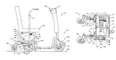
- FIG. 1is a side elevational view of a PMV embodying an aspect of the present invention, shown on a level surface.
- FIG. 2is a side elevational view thereof, shown tipping backwards on an inclined, sloping surface.
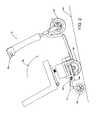
- FIG. 3is an upper, front, left side perspective view of the PMV, particularly showing a flame thereof.
- FIG. 4is a top plan view thereof
- FIG. 5is a left side elevational view thereof.
- FIG. 6is a rear elevational view thereof.
- FIG. 7is an upper, left side perspective view thereof.
- FIG. 8is an enlarged, fragmentary, detailed view of an anti-tip spring mechanism thereof.
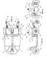
- FIG. 9is an upper, front, left side perspective view of a rear subframe and an anti-tip suspension thereof.
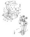
- FIG. 10is an upper, right side perspective view thereof.
- FIG. 11is a right side elevational view of the PMV on a convex surface.
- FIG. 12is a right side elevational view of the PMV on a declined sloping surface.
- FIG. 13is a right side elevational view of the PMV on a concave surface.
- FIG. 14is a fragmentary, right side elevational view of a PMV embodying another aspect of the invention with a modified rear subframe and a modified anti-tip suspension, shown on a level surface.
- FIG. 15is a fragmentary, right side elevational view thereof, showing the rear subframe tipping backwards and resisted by the anti-tip suspension.
- FIG. 16is a fragmentary, right side elevational view of a PMV embodying another aspect of the invention.
- the reference numeral 2generally designates a personal mobility vehicle (PMV) embodying the present invention.
- PMVpersonal mobility vehicle
- the PMV 2generally includes a frame 4 , an anti-tip suspension 5 , a steering mechanism 7 and a drivetrain 9 .
- the frame 4includes front and rear frame ends 6 , 8 and opposite frame sides 10 .
- the frame 4optionally includes front and rear subframes 12 , 14 , which can be releasably interconnected by a tongue-and-socket connection 16 , which is locked by a removable retaining pin 18 ( FIG. 3 ) accessible to the user.
- a seat 24is mounted on a tubular column 26 extending upwardly from the rear subframe 14 . The weight of the rider generally exerts a downward vertical (Z direction) gravitational force F Z through the column 26 to the frame 4 .
- the rear subframe 14includes a front leg 28 , which can comprise a channel section.
- a tongue 29is mounted on and extends forwardly from the front leg 28 for selective insertion in a socket in the front subframe 12 to form the tongue-and-socket connection 16 .
- the rear subframe 14further includes a top platform 30 with front and rear transverse angle sections 32 , 34 defining a battery tray 35 therebetween and a pair of suspension mounts comprising rear support legs 36 with rear support leg upper ends 38 affixed to the rear angle section 34 .
- the rear support legs 36depend downwardly from the rear angle section 34 and terminate at support leg lower ends 40 . Stop rods 42 are attached to the support legs 36 and extend laterally outwardly therefrom.
- a pair of adjustable-height spacers 43are mounted on the rear of the front subframe 12 and include height adjustment bolts 44 adapted to selectively engage the rear subframe top platform 30 .
- the height adjustment bolts 44are adapted for fine adjustments to level the top platform 30 relative to the front subframe 12 . Such adjustments may be necessary to vertically align, plumb and level the tiller 20 , the seat column 26 and other components of the PMV 2 .
- the anti-tip suspension 5includes a pair of trailing arms 46 .
- Each trailing arm 46includes front and rear sections 48 , 50 terminating at front and rear ends 52 , 54 respectively.
- An offset intermediate section 56extends generally upwardly and rearwardly from each trailing arm front section 48 to its respective rear section 50 whereby the trailing arm rear sections 50 are positioned generally parallel to and above the trailing arm front sections 48 .
- the underside of each trailing arm front section 48mounts an axle bushing 58 , which can include a suitable rubber vibration-dampening spacer 60 .
- a rear leg pivotal connection and bushing 62is also mounted on the underside of each trailing arm front section 48 and is located rearwardly from a respective axle bushing 58 .
- the rear leg connections/bushings 62define a transverse (X direction, see FIG. 3 ) pivotal axis for the suspension 5 .
- a counter-rotation mechanismcomprising an anti-tip resilient or spring assembly 64 ( FIG. 8 ) is mounted on each trailing arm intermediate section 56 by a mounting plate 66 , which is attached (e.g., welded) to the intermediate section 56 and extends transversely inwardly therefrom.
- a bolt 68includes a head 70 positioned behind the mounting plate 66 , a shaft 72 extending therethrough and a distal end 74 .
- the bolt shaft 72is received in a compression member 76 , such as a spring, which is retained between the mounting plate 66 at one end and a washer 78 and a compression-adjusting lock nut 80 at the other end.
- the distal end 74is preferably spaced a short distance (typically a fraction of an inch) from a respective rear leg 36 . Such spacing defines a resilient assembly clearance C ( FIG. 8 ), which accommodates a limited amount of suspension 5 rotation before the resilient assembly 64 engages a respective rear support leg 36 . Tightening the lock nut 80 on the bolt 68 compresses the spring 76 and thereby increases the anti-tip, counter-rotating force F Y exerted by the resilient assembly 64 as a function of the applicable spring constant K.
- Other suitable mechanical fastenerscan be used in place of the bolt 68 .
- a pair of anti-tip trailing wheels 82are swivel-mounted on respective trailing arm rear ends 54 .
- Other suitable ground-engaging componentssuch as rollers, skids and the like, can used in place of the trailing wheels 82 .
- Such larger-diameter wheelstend to handle obstacles better than smaller-diameter wheels, because the former are generally better able to roll over larger obstacles.
- Such obstacle-handling capabilitiescan be particularly useful outdoors, where many obstacles, both natural and man-made, are commonly encountered. Without compromising the maneuverability advantage attributable to a relatively short wheelbase (i.e. distance from the front wheel 22 to main wheels 88 ), the anti-tip suspension 5 , the large trailing wheels 82 and other features of the unique suspension 5 enable the PMV 2 to effectively negotiate a relatively wide variety of field conditions.
- the front subframe 12mounts the steering mechanism 7 including a tiller 20 , which mounts a steering front wheel 22 .
- the tiller 20can be equipped with various controls for convenient access by the operator. Such controls can optionally include speed control (e.g. throttle or potentiometer), directional control (e.g., forward and reverse), lights, horn, brakes, etc.
- the tiller 20can be adjustable fore-and-aft and otherwise in order to accommodate various operators.
- the drivetrain 9includes a bidirectional, electric motor 84 drivingly connected to a transaxle 86 , which extends through the axle bushings 58 and mounts the main wheels 88 , one or both of which are preferably driven.
- the vehicle 2could be provided with a pair of motors each driving a respective main wheel 88 , a front-mounted motor driving the steering front wheel 22 or a manual propulsion system.
- the transaxle 86defines a transverse (X direction) main or drive wheel rotational axis.
- an electric motor 84is shown, one or more other suitable motors, including internal combustion, can be utilized.
- One or more (two are shown) batteries 90are located in the battery tray 35 and are electrically connected to the motor 84 through suitable connections and controls.
- a pair of battery spacers 91are mounted in the top platform angle sections 32 , 34 and separate the batteries 90 .
- theycan comprise, for example, AGM-type gel sealed lead acid batteries, which can be laid on their sides in the battery tray 35 .
- the PMV 2can be equipped with suitable driving and parking brake systems.
- a brake release 85is shown for releasing a parking brake mechanism in the motor 84 .
- the anti-tip suspension 5accommodates a variety of operators of different sizes while traversing various surface and terrain conditions, which can be encountered both indoors and out.
- stability and anti-tip functionalityare achieved by maintaining all five wheels in ground contact under operating conditions, which can include incline and decline sloping surfaces.
- FIG. 1shows the PMV 2 on a flat, level surface 92 .
- the spring assemblies 64are disengaged at clearances C, i.e. the bolt distal ends 74 are in spaced relation from the rear support legs 36 ( FIG. 8 ).
- the suspension 5distributes the vehicle and operator loads over all of the wheels, with the majority being placed on the main wheels 88 as a function of the proximity of the rider gravitational load F Z to the transaxle 86 rotational axis, as indicated by the dimension Y. 1 ( FIG. 1 ).
- Dimension Y. 2represents the longitudinal distance between the transaxle 86 /main wheel 88 and suspension 5 rotational axes, and is also relatively short.
- Dimension Y. 3represents the distance between the suspension 5 rotational axis and the rotational axis of the trailing wheels 82 , which is somewhat greater than Y. 1 and Y. 2 .
- the predetermined clearances C between the bolt distal ends 74 and the rear support legs 36can accommodate a limited amount of relative movement between the rear subframe 14 and the anti-tip suspension 5 . Minor surface undulations and irregularities are thus accommodated without involvement of the spring assemblies 64 .
- the spring assemblies 64function to maintain the steering front wheel 22 in contact with the surface 94 .
- the geometry of the suspension 5enhances stability and safety by exerting an anti-tip, counter-rotating force, as indicated by the arrow 96 .
- the rotational axes of the transaxle 86 and the leg-to-suspension pivotal connections 62are both located below the trailing arm front sections 48 .
- the spring 76operates along a longitudinal axis (F Y in FIG. 8 ) extending fore-and-aft above the trailing arm front section 48 . The spring 76 thus operates across a lever arm defined by this geometry.
- the spring assemblies 64apply a counter-rotational force (arrow 96 in FIG. 2 ) to the frame 4 , which tends tend to push the steering front wheel 22 back down upon encountering a backwards, tip-over condition.
- the adjustability of the compression springs 76enables the PMV 2 to be suitably adjusted for various loads and surfaces in order to prevent such a backward tip-over accident. Heavier loads and steeper inclines would generally require greater compression on the springs 76 and vice versa.
- FIG. 11A convex surface 98 condition is shown in FIG. 11 whereby the spring distal ends 74 disengage from the support legs 36 and the stop rods 42 engage the trailing arm front sections 48 .
- the stop rods 42thus function to restrict downward rotation of the suspension 5 (counterclockwise as shown in FIG. 11 ).
- a decline sloping surface 100is shown in FIG. 12 with the suspension 5 positioned substantially as it would be for a level condition ( FIG. 1 ).
- the mounting of the suspension 5 on the rear subframe 14 with the rotational axes for the suspension 5 and the transaxle 86 below the trailing arm front sections 48i.e. the lowest parts of the trailing arms 46 ) enhances stability, particularly when the brakes are applied. It will be appreciated that brake application on a decline ( FIG.
- FIG. 13shows a concave travel surface 104 and the suspension 5 rotated slightly clockwise (as shown FIG. 13 ) relative to the frame 4 .
- Relatively shallow concave conditionsare accommodated without compressing the spring assemblies 64 because the resilient assembly/rear support leg clearances C accommodate smaller, incremental rotations.
- the geometry of the PMV 2tends to maintain a relatively constant proportional weight distribution of the PMV 2 throughout a range of conditions from empty (no rider or cargo) through loads of 200 pounds and more.
- the relative placements of the rider center of mass (acting along gravitational force arrow F Z ), the main wheel rotational axis at 58 , the suspension pivotal axis at 62 and the trailing wheel 82 rotational axiscooperate to maintain relatively constant proportional weight distribution on the main wheels 88 .
- the loadcan comprise one or more riders and various objects, which can be placed on the PMV 2 or the rider(s).
- the weight distribution for empty and 200 pound load conditionsis shown in the following table:
- a PMV 122comprising a first modified aspect or embodiment of the invention is shown in FIGS. 14 and 15 and includes a modified rear subframe 123 and a modified anti-tip suspension 124 .
- the rear subframe 123includes a pair of extension arms 125 .
- the suspension 124includes a pair of trailing arms 126 each having front, intermediate and rear sections 128 , 129 and 130 .
- the trailing arm front sections 128are pivotally connected to rear support legs 134 of the rear subframe 123 at pivotal connections 138 , which define a subframe rotational axis.
- a pair of counter-rotational spring assemblies 140each includes a bolt 142 with a head 144 and a threaded shank 146 .
- the shank 146extends through vertically aligned receivers in a respective rear subframe extension arm 125 and a respective trailing arm front subframe 128 .
- a compression spring 148receives the shank 146 and is compressible between the extension arm 135 and the trailing arm front subframe 128 .
- the shank 146threadably mounts a self-locking wing nut 152 below the trailing arm front subframe 128 whereby the range of rotation is adjustable, as described above.
- the bolt 142 and the nut 152adjustably limit rotation of the suspension subframe 124 in a counterclockwise direction (as shown in FIG. 14 ).
- the modified aspect PMV 122otherwise functions substantially similarly to the PMV 2 described above. As shown in FIG. 15 , any tendency to tip rearwardly while ascending a positive incline 94 is effectively resisted by the compression springs 148 , which are compressed between the extension arms 125 and the trailing arm front sections 128 .
- the springs 148exert an anti-tip, counter-rotational force, as indicated by arrow 154 ( FIG. 15 ).
- Other components of the PMV 122can be substantially similar to the PMV 2 described above, such as the front subframe, the drivetrain, etc. Force adjustability via the spring assemblies 140 can be achieved by changing the springs 148 . For example, pairs of springs 148 can be provided to accommodate various sizes of riders and different operating conditions.
- Spring compressioncan also be adjusted by providing suitable adjusting nuts and lock nuts on the bolts 142 whereby the anti-tipping force applied in the direction of the force arrow 154 can be adjusted as needed.
Landscapes
- Engineering & Computer Science (AREA)
- Mechanical Engineering (AREA)
- Health & Medical Sciences (AREA)
- Life Sciences & Earth Sciences (AREA)
- Animal Behavior & Ethology (AREA)
- General Health & Medical Sciences (AREA)
- Public Health (AREA)
- Veterinary Medicine (AREA)
- Vehicle Body Suspensions (AREA)
- Body Structure For Vehicles (AREA)
Abstract
Description
| TABLE 1 |
| Proportional Weight Distribution |
| Steering Front | ||||
| Wheel | Main Wheels | Trailing Wheels | ||
| No Load | 22.5% | 55.0% | 22.5% |
| 200 Pound Load | 20.6% | 56.4% | 23.1% |
Claims (20)
Priority Applications (1)
| Application Number | Priority Date | Filing Date | Title |
|---|---|---|---|
| US12/505,696US7942445B2 (en) | 2006-06-19 | 2009-07-20 | Personal mobility vehicle with anti-tip suspension |
Applications Claiming Priority (2)
| Application Number | Priority Date | Filing Date | Title |
|---|---|---|---|
| US11/455,564US7562903B2 (en) | 2006-06-19 | 2006-06-19 | Personal mobility vehicle with anti-tip suspension |
| US12/505,696US7942445B2 (en) | 2006-06-19 | 2009-07-20 | Personal mobility vehicle with anti-tip suspension |
Related Parent Applications (1)
| Application Number | Title | Priority Date | Filing Date |
|---|---|---|---|
| US11/455,564ContinuationUS7562903B2 (en) | 2006-06-19 | 2006-06-19 | Personal mobility vehicle with anti-tip suspension |
Publications (2)
| Publication Number | Publication Date |
|---|---|
| US20090302589A1 US20090302589A1 (en) | 2009-12-10 |
| US7942445B2true US7942445B2 (en) | 2011-05-17 |
Family
ID=38860805
Family Applications (2)
| Application Number | Title | Priority Date | Filing Date |
|---|---|---|---|
| US11/455,564Expired - Fee RelatedUS7562903B2 (en) | 2006-06-19 | 2006-06-19 | Personal mobility vehicle with anti-tip suspension |
| US12/505,696Active2026-10-11US7942445B2 (en) | 2006-06-19 | 2009-07-20 | Personal mobility vehicle with anti-tip suspension |
Family Applications Before (1)
| Application Number | Title | Priority Date | Filing Date |
|---|---|---|---|
| US11/455,564Expired - Fee RelatedUS7562903B2 (en) | 2006-06-19 | 2006-06-19 | Personal mobility vehicle with anti-tip suspension |
Country Status (1)
| Country | Link |
|---|---|
| US (2) | US7562903B2 (en) |
Cited By (12)
| Publication number | Priority date | Publication date | Assignee | Title |
|---|---|---|---|---|
| US20090145677A1 (en)* | 2006-08-16 | 2009-06-11 | Sunrise Medical Hhg Inc. | Personal mobility vehicle having a pivoting suspension with a torque activated release mechanism |
| US20100300790A1 (en)* | 2009-05-29 | 2010-12-02 | Lucas Tong | Battery-powered motorized vehicle with a carrying platform |
| US20110083914A1 (en)* | 2009-10-12 | 2011-04-14 | Pride Mobility Products Corporation | Wheelchair |
| US20110231059A1 (en)* | 2010-03-22 | 2011-09-22 | Hanna Timothy T | Self-centering, torque-sensing joint assembly for a pallet truck power steering system |
| US20110231058A1 (en)* | 2010-03-22 | 2011-09-22 | Hanna Timothy T | Self-centering, Torque-sensing Joint Assembly For A Pallet Truck Power Steering System |
| US20120273283A1 (en)* | 2005-08-18 | 2012-11-01 | Sunrise Medical Hhg, Inc. | Midwheel drive wheelchair with independent front and rear suspension |
| US20150196438A1 (en)* | 2013-12-16 | 2015-07-16 | Pride Mobility Products Corporation | Elevated Height Wheelchair |
| US9242544B2 (en)* | 2011-09-23 | 2016-01-26 | Kanzaki Kokyukoki Mfg. Co., Ltd. | Vehicle with electric transaxle |
| WO2016152966A1 (en)* | 2015-03-24 | 2016-09-29 | 地方独立行政法人東京都立産業技術研究センター | Rocker bogie |
| US10335330B2 (en) | 2017-03-02 | 2019-07-02 | Travelsys4u Ltd. | Motor-driven chair steered by seat rotation |
| US10772774B2 (en) | 2016-08-10 | 2020-09-15 | Max Mobility, Llc | Self-balancing wheelchair |
| US11191685B2 (en) | 2016-02-27 | 2021-12-07 | Pride Mobility Products Corporation | Adjustable height wheelchair |
Families Citing this family (8)
| Publication number | Priority date | Publication date | Assignee | Title |
|---|---|---|---|---|
| EP1732490B1 (en)* | 2004-04-08 | 2010-07-07 | Levo AG | Wheelchair comprising a central wheel drive unit, particularly elevated wheelchair |
| US20070063499A1 (en)* | 2005-09-19 | 2007-03-22 | Chun-Pi Shem | Anti-tilting suspension for an electric motorcycle |
| US7882909B2 (en)* | 2006-09-14 | 2011-02-08 | University Of Pittsburgh | Personal vehicle |
| US20100060023A1 (en)* | 2008-09-05 | 2010-03-11 | Terry Wayne Adkins | ATV universal safety bar |
| US8286738B2 (en)* | 2009-07-14 | 2012-10-16 | Merits Health Products Co., Ltd. | Wheel set structure of an electric wheelchair |
| US20130197732A1 (en)* | 2012-01-26 | 2013-08-01 | Jonathan L. Pearlman | Active stability devices and systems for mobile devices |
| FR3039393B1 (en)* | 2015-07-30 | 2021-11-12 | Rupiani | WHEELCHAIR WITH ANTI-TIPPING SYSTEM |
| US10597005B1 (en)* | 2019-04-02 | 2020-03-24 | Phillip R. C. Latham | Anti-tip device for ATV |
Citations (28)
| Publication number | Priority date | Publication date | Assignee | Title |
|---|---|---|---|---|
| US5036938A (en)* | 1989-03-13 | 1991-08-06 | Blount Wendell G | Disassemblable riding scooter |
| US5435404A (en)* | 1992-07-31 | 1995-07-25 | Garin, Iii; Paul V. | Powered mobility chair for individual |
| US5964473A (en) | 1994-11-18 | 1999-10-12 | Degonda-Rehab S.A. | Wheelchair for transporting or assisting the displacement of at least one user, particularly for handicapped person |
| US6041876A (en) | 1997-10-06 | 2000-03-28 | Invacare Corporation | Anti-tip assembly for power wheelchair |
| US6135222A (en)* | 1998-09-11 | 2000-10-24 | Nissin Medical Industries Co., Ltd. | Installing structure for an electrically-driven wheelchair |
| US6206119B1 (en)* | 1999-05-05 | 2001-03-27 | Donald P. H. Wu | Electrical wheelchair with double frame structure |
| US6439331B1 (en)* | 2000-08-21 | 2002-08-27 | Ju-Yu Fan | Chassis of an electric walk-substituting car |
| US6460641B1 (en)* | 2000-06-29 | 2002-10-08 | Invacare Corporation | Mid-wheel drive wheelchair with front wheel multiple bias suspension and anti-tip assembly |
| US6530446B1 (en) | 2001-10-15 | 2003-03-11 | Samuel Lin | Separable frame for an electric scooter |
| US6533306B2 (en) | 2001-01-18 | 2003-03-18 | Pride Mobility Products Corporation | Adjustable height anti-tip wheels for a power wheelchair |
| US6543798B2 (en) | 2000-04-04 | 2003-04-08 | Pride Mobility Products Corporation | Anti-tip caster suspension for a wheelchair |
| US6554086B1 (en) | 2000-10-27 | 2003-04-29 | Invacare Corporation | Obstacle traversing wheelchair |
| US6601863B1 (en) | 1997-10-06 | 2003-08-05 | Invacare Corporation | Mid-wheel drive wheelchair with rigid front wheel anti-tip stabilizer |
| US6640916B2 (en) | 1996-07-03 | 2003-11-04 | Pride Mobility Products, Corporation | Mid-wheel drive power wheelchair |
| US6672606B1 (en)* | 2000-10-05 | 2004-01-06 | Electric Mobility Corporation | Suspension for personal mobility vehicle |
| US6712369B2 (en)* | 2002-02-28 | 2004-03-30 | Pihsiang Machinery Mfg. Co., Ltd. | Anti-turnover mechanism of electrical wheelchair |
| US6773032B2 (en)* | 1999-06-06 | 2004-08-10 | Don L. Redman | Ambulatory apparatus |
| US6896084B2 (en) | 2003-05-23 | 2005-05-24 | Chiu Hsiang Lo | Wheeled vehicle having a detachable rear frame |
| US6926106B2 (en) | 1999-10-12 | 2005-08-09 | Invacare Corporation | Wheelchair having speed and direction control touchpad |
| US6938923B2 (en) | 2002-04-30 | 2005-09-06 | Pride Mobility Products Corporation | Power wheelchair |
| US20050206149A1 (en)* | 2004-03-16 | 2005-09-22 | Mulhern James P | Bi-directional anti-tip system for powered wheelchairs |
| US7104346B2 (en)* | 2003-03-25 | 2006-09-12 | Schaffner Walter E | Power wheelchair |
| US20070063499A1 (en)* | 2005-09-19 | 2007-03-22 | Chun-Pi Shem | Anti-tilting suspension for an electric motorcycle |
| US20070209848A1 (en)* | 2006-03-08 | 2007-09-13 | Chenghui Tang | Jointed mechanism of electric wheelchair |
| US7270208B2 (en)* | 2005-12-30 | 2007-09-18 | Taiwan An I Co., Ltd. | Battery carrier sliding device of an electrical wheel chair |
| US7273118B2 (en)* | 2005-07-25 | 2007-09-25 | Shao-Shih Huang | Electric wheelchair frame |
| US7293801B2 (en) | 2003-08-18 | 2007-11-13 | Invacare Corporation | Self-stabilizing suspension for wheeled vehicles |
| US7389835B2 (en)* | 2003-10-08 | 2008-06-24 | Pride Mobility Products Corporation | Active anti-tip system for power wheelchairs |
Family Cites Families (2)
| Publication number | Priority date | Publication date | Assignee | Title |
|---|---|---|---|---|
| FR2809693B1 (en)* | 2000-05-30 | 2002-09-13 | Livbag Snc | HYBRID GENERATOR WITH PERFORATOR PILLAR AND BI-TUBULAR BODY |
| JP2003216640A (en)* | 2001-11-19 | 2003-07-31 | Matsushita Electric Ind Co Ltd | Data processing device and data processing method |
- 2006
- 2006-06-19USUS11/455,564patent/US7562903B2/ennot_activeExpired - Fee Related
- 2009
- 2009-07-20USUS12/505,696patent/US7942445B2/enactiveActive
Patent Citations (33)
| Publication number | Priority date | Publication date | Assignee | Title |
|---|---|---|---|---|
| US5036938A (en)* | 1989-03-13 | 1991-08-06 | Blount Wendell G | Disassemblable riding scooter |
| US5435404A (en)* | 1992-07-31 | 1995-07-25 | Garin, Iii; Paul V. | Powered mobility chair for individual |
| US5964473A (en) | 1994-11-18 | 1999-10-12 | Degonda-Rehab S.A. | Wheelchair for transporting or assisting the displacement of at least one user, particularly for handicapped person |
| US6640916B2 (en) | 1996-07-03 | 2003-11-04 | Pride Mobility Products, Corporation | Mid-wheel drive power wheelchair |
| US6041876A (en) | 1997-10-06 | 2000-03-28 | Invacare Corporation | Anti-tip assembly for power wheelchair |
| US6131679A (en) | 1997-10-06 | 2000-10-17 | Invacare Corporation | Anti-tip assembly for power wheelchair |
| US6601863B1 (en) | 1997-10-06 | 2003-08-05 | Invacare Corporation | Mid-wheel drive wheelchair with rigid front wheel anti-tip stabilizer |
| US6135222A (en)* | 1998-09-11 | 2000-10-24 | Nissin Medical Industries Co., Ltd. | Installing structure for an electrically-driven wheelchair |
| US6206119B1 (en)* | 1999-05-05 | 2001-03-27 | Donald P. H. Wu | Electrical wheelchair with double frame structure |
| US6773032B2 (en)* | 1999-06-06 | 2004-08-10 | Don L. Redman | Ambulatory apparatus |
| US6926106B2 (en) | 1999-10-12 | 2005-08-09 | Invacare Corporation | Wheelchair having speed and direction control touchpad |
| US6543798B2 (en) | 2000-04-04 | 2003-04-08 | Pride Mobility Products Corporation | Anti-tip caster suspension for a wheelchair |
| US6460641B1 (en)* | 2000-06-29 | 2002-10-08 | Invacare Corporation | Mid-wheel drive wheelchair with front wheel multiple bias suspension and anti-tip assembly |
| US6439331B1 (en)* | 2000-08-21 | 2002-08-27 | Ju-Yu Fan | Chassis of an electric walk-substituting car |
| US6672606B1 (en)* | 2000-10-05 | 2004-01-06 | Electric Mobility Corporation | Suspension for personal mobility vehicle |
| US6554086B1 (en) | 2000-10-27 | 2003-04-29 | Invacare Corporation | Obstacle traversing wheelchair |
| US7219755B2 (en) | 2000-10-27 | 2007-05-22 | Invacre Corp. | Obstacle traversing wheelchair |
| US6923280B2 (en) | 2000-10-27 | 2005-08-02 | Invacare Corporation | Obstacle traversing wheelchair |
| US6533306B2 (en) | 2001-01-18 | 2003-03-18 | Pride Mobility Products Corporation | Adjustable height anti-tip wheels for a power wheelchair |
| US6530446B1 (en) | 2001-10-15 | 2003-03-11 | Samuel Lin | Separable frame for an electric scooter |
| US6712369B2 (en)* | 2002-02-28 | 2004-03-30 | Pihsiang Machinery Mfg. Co., Ltd. | Anti-turnover mechanism of electrical wheelchair |
| US6938923B2 (en) | 2002-04-30 | 2005-09-06 | Pride Mobility Products Corporation | Power wheelchair |
| US7104346B2 (en)* | 2003-03-25 | 2006-09-12 | Schaffner Walter E | Power wheelchair |
| US6896084B2 (en) | 2003-05-23 | 2005-05-24 | Chiu Hsiang Lo | Wheeled vehicle having a detachable rear frame |
| US7293801B2 (en) | 2003-08-18 | 2007-11-13 | Invacare Corporation | Self-stabilizing suspension for wheeled vehicles |
| US7389835B2 (en)* | 2003-10-08 | 2008-06-24 | Pride Mobility Products Corporation | Active anti-tip system for power wheelchairs |
| US20050206149A1 (en)* | 2004-03-16 | 2005-09-22 | Mulhern James P | Bi-directional anti-tip system for powered wheelchairs |
| US7264272B2 (en) | 2004-03-16 | 2007-09-04 | Pride Mobility Products Corporation | Bi-directional anti-tip system for powered wheelchairs |
| US7273118B2 (en)* | 2005-07-25 | 2007-09-25 | Shao-Shih Huang | Electric wheelchair frame |
| US20070063499A1 (en)* | 2005-09-19 | 2007-03-22 | Chun-Pi Shem | Anti-tilting suspension for an electric motorcycle |
| US7270208B2 (en)* | 2005-12-30 | 2007-09-18 | Taiwan An I Co., Ltd. | Battery carrier sliding device of an electrical wheel chair |
| US20070209848A1 (en)* | 2006-03-08 | 2007-09-13 | Chenghui Tang | Jointed mechanism of electric wheelchair |
| US7516984B2 (en) | 2006-03-08 | 2009-04-14 | Chenghui Tang | Jointed mechanism of electric wheelchair |
Non-Patent Citations (4)
| Title |
|---|
| "Invacare Product Catalog", Invacare 400 Cady Red 18'' Seat, www.invacare.com, Apr. 29, 2006. |
| "Invacare Product Catalog", Invacare 400 Cady Red 18″ Seat, www.invacare.com, Apr. 29, 2006. |
| "Invacare Zoom Product Literature", www.invacare.com, Apr. 29, 2006. |
| "Vehicles Technology, VCS-S5", www.vcvehicles.com, Apr. 29, 2006. |
Cited By (36)
| Publication number | Priority date | Publication date | Assignee | Title |
|---|---|---|---|---|
| US20120273283A1 (en)* | 2005-08-18 | 2012-11-01 | Sunrise Medical Hhg, Inc. | Midwheel drive wheelchair with independent front and rear suspension |
| US8469383B2 (en)* | 2005-08-18 | 2013-06-25 | Sunrise Medical (Us) Llc | Midwheel drive wheelchair with independent front and rear suspension |
| US20090145677A1 (en)* | 2006-08-16 | 2009-06-11 | Sunrise Medical Hhg Inc. | Personal mobility vehicle having a pivoting suspension with a torque activated release mechanism |
| US8113531B2 (en)* | 2006-08-16 | 2012-02-14 | Sunrise Medical Hhg, Inc. | Personal mobility vehicle having a pivoting suspension with a torque activated release mechanism |
| US8596652B2 (en)* | 2009-05-29 | 2013-12-03 | Lucas Hou-Wae Tong | Battery-powered motorized vehicle with a carrying platform |
| US20100300790A1 (en)* | 2009-05-29 | 2010-12-02 | Lucas Tong | Battery-powered motorized vehicle with a carrying platform |
| US20110083914A1 (en)* | 2009-10-12 | 2011-04-14 | Pride Mobility Products Corporation | Wheelchair |
| US9468571B2 (en) | 2009-10-12 | 2016-10-18 | Pride Mobility Products Corporation | Wheelchair |
| US10272004B2 (en) | 2009-10-12 | 2019-04-30 | Pride Mobility Products Corporation | Wheelchair |
| US8616309B2 (en)* | 2009-10-12 | 2013-12-31 | Pride Mobility Products Corporation | Wheelchair |
| US20110231059A1 (en)* | 2010-03-22 | 2011-09-22 | Hanna Timothy T | Self-centering, torque-sensing joint assembly for a pallet truck power steering system |
| US8504241B2 (en) | 2010-03-22 | 2013-08-06 | The Raymond Corporation | Self-centering, torque-sensing joint assembly for a pallet truck power steering system |
| US8467937B2 (en)* | 2010-03-22 | 2013-06-18 | The Raymond Corporation | Self-centering, torque-sensing joint assembly for a pallet truck power steering system |
| US20110231058A1 (en)* | 2010-03-22 | 2011-09-22 | Hanna Timothy T | Self-centering, Torque-sensing Joint Assembly For A Pallet Truck Power Steering System |
| US9242544B2 (en)* | 2011-09-23 | 2016-01-26 | Kanzaki Kokyukoki Mfg. Co., Ltd. | Vehicle with electric transaxle |
| US9566200B2 (en)* | 2013-12-16 | 2017-02-14 | Pride Mobility Products Corporation | Elevated height wheelchair |
| US10588797B2 (en) | 2013-12-16 | 2020-03-17 | Pride Mobility Products Corporation | Elevated height wheelchair |
| US9351889B2 (en)* | 2013-12-16 | 2016-05-31 | Pride Mobility Products Corporation | Elevated height wheelchair |
| US20150196441A1 (en)* | 2013-12-16 | 2015-07-16 | Pride Mobility Products Corporation | Elevated Height Wheelchair |
| US11998495B2 (en) | 2013-12-16 | 2024-06-04 | P{ride Mobility Products Corporation | Elevated height wheelchair |
| US9808383B2 (en)* | 2013-12-16 | 2017-11-07 | Pride Mobility Products Corporation | Elevated height wheelchair |
| US11571345B2 (en) | 2013-12-16 | 2023-02-07 | Pride Mobility Products Corporation | Elevated height wheelchair |
| US10130532B2 (en) | 2013-12-16 | 2018-11-20 | Pride Mobility Products Corporation | Elevated height wheelchair |
| US20150196438A1 (en)* | 2013-12-16 | 2015-07-16 | Pride Mobility Products Corporation | Elevated Height Wheelchair |
| US11141330B2 (en) | 2013-12-16 | 2021-10-12 | Pride Mobility Products Corporation | Elevated height wheelchair |
| US10828212B2 (en) | 2013-12-16 | 2020-11-10 | Pride Mobility Products Corporation | Elevated height wheelchair |
| US10687997B2 (en) | 2013-12-16 | 2020-06-23 | Pride Mobility Products Corporation | Elevated height wheelchair |
| US10561548B1 (en) | 2013-12-16 | 2020-02-18 | Pride Mobility Products Corporation | Elevated height wheelchair |
| CN107614366A (en)* | 2015-03-24 | 2018-01-19 | 地方独立行政法人东京都立产业技术研究中心 | rocker bogie |
| CN107614366B (en)* | 2015-03-24 | 2019-08-02 | 地方独立行政法人东京都立产业技术研究中心 | Rocker-arm bogie |
| US10336380B2 (en) | 2015-03-24 | 2019-07-02 | Tokyo Metropolitan Industrial Technology Research Institute | Rocker bogie |
| WO2016152966A1 (en)* | 2015-03-24 | 2016-09-29 | 地方独立行政法人東京都立産業技術研究センター | Rocker bogie |
| JPWO2016152966A1 (en)* | 2015-03-24 | 2017-07-13 | 地方独立行政法人東京都立産業技術研究センター | Rocker bogie |
| US11191685B2 (en) | 2016-02-27 | 2021-12-07 | Pride Mobility Products Corporation | Adjustable height wheelchair |
| US10772774B2 (en) | 2016-08-10 | 2020-09-15 | Max Mobility, Llc | Self-balancing wheelchair |
| US10335330B2 (en) | 2017-03-02 | 2019-07-02 | Travelsys4u Ltd. | Motor-driven chair steered by seat rotation |
Also Published As
| Publication number | Publication date |
|---|---|
| US7562903B2 (en) | 2009-07-21 |
| US20070290492A1 (en) | 2007-12-20 |
| US20090302589A1 (en) | 2009-12-10 |
Similar Documents
| Publication | Publication Date | Title |
|---|---|---|
| US7942445B2 (en) | Personal mobility vehicle with anti-tip suspension | |
| US5651422A (en) | Universal-fit, quick-connect power drive/steer attachment for wheelchair | |
| US4274647A (en) | Manually steerable skateboard | |
| US6860512B2 (en) | Utility motor vehicle with carrier | |
| US9669857B1 (en) | Propulsion device for hand-pushed equipment | |
| US5435404A (en) | Powered mobility chair for individual | |
| US6220382B1 (en) | Powered wheelchair with separating frame | |
| US6341657B1 (en) | Suspension for central drive vehicle | |
| US6176335B1 (en) | Power wheelchair | |
| AU2008203294B2 (en) | Wheelchair suspension | |
| US4513832A (en) | Wheeled chassis | |
| US6640916B2 (en) | Mid-wheel drive power wheelchair | |
| US5351774A (en) | Powered wheelchair with a detachable power drive assembly | |
| US9320661B2 (en) | Electric mid-wheel drive wheelchair | |
| US4892166A (en) | Motorized wheelchair assembly having coupling device | |
| US8336904B2 (en) | Modular wheelchair with in-line chassis | |
| US8585071B2 (en) | Releasable forward wheel apparatus for a wheelchair | |
| US5697465A (en) | Personal mobility vehicle | |
| CA2487935A1 (en) | Mid-wheel drive scooter | |
| US20100193278A1 (en) | Powered drive apparatus for wheelchair | |
| EP0869021B1 (en) | Self-propelled vehicle | |
| US20050016780A1 (en) | Portable mid-wheel drive scooter | |
| US20060055143A1 (en) | Rear wheel mount and optional suspension for wheelchair | |
| GB2563083A (en) | Rear attendant standing platform for a manual or self propelled wheelchair adapted with a battery powered propulsion system | |
| CA2249515A1 (en) | Motorized chair base |
Legal Events
| Date | Code | Title | Description |
|---|---|---|---|
| AS | Assignment | Owner name:BURKE, INC., KANSAS Free format text:ASSIGNMENT OF ASSIGNORS INTEREST;ASSIGNORS:KRAMER, DUWAYNE E.;MELLIES, BRIAN W.;REEL/FRAME:022976/0293 Effective date:20060615 | |
| STCF | Information on status: patent grant | Free format text:PATENTED CASE | |
| FPAY | Fee payment | Year of fee payment:4 | |
| FEPP | Fee payment procedure | Free format text:MAINTENANCE FEE REMINDER MAILED (ORIGINAL EVENT CODE: REM.); ENTITY STATUS OF PATENT OWNER: SMALL ENTITY | |
| FEPP | Fee payment procedure | Free format text:7.5 YR SURCHARGE - LATE PMT W/IN 6 MO, SMALL ENTITY (ORIGINAL EVENT CODE: M2555); ENTITY STATUS OF PATENT OWNER: SMALL ENTITY | |
| MAFP | Maintenance fee payment | Free format text:PAYMENT OF MAINTENANCE FEE, 8TH YR, SMALL ENTITY (ORIGINAL EVENT CODE: M2552); ENTITY STATUS OF PATENT OWNER: SMALL ENTITY Year of fee payment:8 | |
| AS | Assignment | Owner name:SIZEWISE RENTALS, L.L.C., KANSAS Free format text:ASSIGNMENT OF ASSIGNORS INTEREST;ASSIGNOR:BURKE, INC.;REEL/FRAME:062101/0834 Effective date:20221206 | |
| FEPP | Fee payment procedure | Free format text:MAINTENANCE FEE REMINDER MAILED (ORIGINAL EVENT CODE: REM.); ENTITY STATUS OF PATENT OWNER: SMALL ENTITY | |
| FEPP | Fee payment procedure | Free format text:11.5 YR SURCHARGE- LATE PMT W/IN 6 MO, LARGE ENTITY (ORIGINAL EVENT CODE: M1556); ENTITY STATUS OF PATENT OWNER: LARGE ENTITY Free format text:ENTITY STATUS SET TO UNDISCOUNTED (ORIGINAL EVENT CODE: BIG.); ENTITY STATUS OF PATENT OWNER: LARGE ENTITY | |
| MAFP | Maintenance fee payment | Free format text:PAYMENT OF MAINTENANCE FEE, 12TH YEAR, LARGE ENTITY (ORIGINAL EVENT CODE: M1553); ENTITY STATUS OF PATENT OWNER: LARGE ENTITY Year of fee payment:12 | |
| AS | Assignment | Owner name:JPMORGAN CHASE BANK, N.A., ILLINOIS Free format text:PATENT SECURITY AGREEMENT;ASSIGNOR:SIZEWISE RENTALS, L.L.C.;REEL/FRAME:064103/0181 Effective date:20230501 |