US7942329B2 - Method for providing user feedback in an autoidentification system - Google Patents
Method for providing user feedback in an autoidentification systemDownload PDFInfo
- Publication number
- US7942329B2 US7942329B2US11/838,289US83828907AUS7942329B2US 7942329 B2US7942329 B2US 7942329B2US 83828907 AUS83828907 AUS 83828907AUS 7942329 B2US7942329 B2US 7942329B2
- Authority
- US
- United States
- Prior art keywords
- target
- reader
- color
- rfid
- illumination source
- Prior art date
- Legal status (The legal status is an assumption and is not a legal conclusion. Google has not performed a legal analysis and makes no representation as to the accuracy of the status listed.)
- Active
Links
Images


Classifications
- G—PHYSICS
- G06—COMPUTING OR CALCULATING; COUNTING
- G06K—GRAPHICAL DATA READING; PRESENTATION OF DATA; RECORD CARRIERS; HANDLING RECORD CARRIERS
- G06K7/00—Methods or arrangements for sensing record carriers, e.g. for reading patterns
- G06K7/0004—Hybrid readers
- G—PHYSICS
- G06—COMPUTING OR CALCULATING; COUNTING
- G06K—GRAPHICAL DATA READING; PRESENTATION OF DATA; RECORD CARRIERS; HANDLING RECORD CARRIERS
- G06K7/00—Methods or arrangements for sensing record carriers, e.g. for reading patterns
- G06K7/10—Methods or arrangements for sensing record carriers, e.g. for reading patterns by electromagnetic radiation, e.g. optical sensing; by corpuscular radiation
- G06K7/10544—Methods or arrangements for sensing record carriers, e.g. for reading patterns by electromagnetic radiation, e.g. optical sensing; by corpuscular radiation by scanning of the records by radiation in the optical part of the electromagnetic spectrum
- G06K7/10712—Fixed beam scanning
- G06K7/10722—Photodetector array or CCD scanning
- G06K7/10732—Light sources
Definitions
- the present inventionrelates to autoidentification systems and, more particularly, to a system and method for providing user feedback using target illumination sources.
- Autoidentification systemssuch as optical imagers and radiofrequency identification (RFID) readers are being used with increasing frequency for a variety of applications, including obtaining medical information or medical data from patients and medication contains, verifying the contents of patient medical samples, or extracting information from labeled products, such as shipping containers or retail items that contain barcodes or RFID tags.
- RFIDradiofrequency identification
- Barcodesare essentially graphic representation of data (alpha, numeric, or both) that is machine-readable. Barcodes encode numbers and letters into different types of symbologies, such as linear codes, two-dimensional codes, and composite codes (a combination of linear and two-dimensional codes). In more recent applications, referred to as digital or optical image capture, an optical device snaps a digital picture of the barcode and software in the imager orients the picture and decodes the barcode(s) contained in the picture.
- Radiofrequency identificationis a wireless communication technology that utilizes radiowaves for automatic identification and data capture of information for the purpose of identifying and tracking objects or people. Signals in the radio frequency (RF) range of the electromagnetic spectrum are used to communicate data between a two transceiver devices.
- An RFID systemtypically consists of the three main components: a tag, a reader, and the software/firmware for controlling the system. Tags are placed on objects or people and directly or indirectly contain information about the object or person. The reader uses RF energy to interrogate the tag and read the information it contains, or even write data to the tag.
- barcode readersmay include on-board illumination sources, such as light-emitting diodes (LEDs) for enhancing the visibility of the target
- LEDslight-emitting diodes
- the housing for the barcode or RFID readermay include LEDs aligned to indicate to the user a successful barcode interpretation or RFID interrogation.
- status LEDsis cumbersome as the user must try to perceive the target barcode or RFID tag and consider the special LEDs at the same, which may not be easily viewed or even in the proximity of the user.
- the present inventionprovides the use of the existing illumination system of a handheld or stand-mounted optical imager, or a combined optical imager and radiofrequency identification (RFID) reader, to reflect the status of operations to the user, i.e., whether the barcode and/or RFID reading was successful or unsuccessful.
- a barcode or RFID deviceis provided with at least two sets of illuminating LEDs that are directed toward a target object. Preferably, red LEDs are used for illuminating barcodes and a second set of LEDs, such as green, may also be provided for enhanced illumination.
- the present inventionilluminates the target with a particular color of light to signify a successful read, such as green light, or an unsuccessful read, such as red light.
- a third colormay be provided to indicate a successful RFID interrogation, such as blue light.
- the present inventionthus uses the built-in illumination LEDs to cast differently colored light on the target, rather than having to provide additional LEDs in a user interface positioned on the housing of the reader.
- FIG. 1is a perspective view of an optical imaging and RFID reader having multicolored illumination sources according to the present invention
- FIG. 2is a schematic of the electronics in an optical imaging and RFID reader having multicolored illumination sources according to the present invention.
- FIG. 3is a schematic of an alternative embodiment of a separate illumination source according to the present invention.
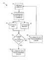
- FIG. 4is a flowchart of a process of controlling a multicolored illumination source according to the present invention.
- FIG. 1a optical imaging and RFID interrogation reader 10 . It should be recognized by those of skill in the art that the present invention may be used in combination with either a barcode reader or an RFID reader, or both and unit 10 is described as having both readers for illustrative purposes only.
- Reader 10generally comprises a microcontroller 12 that interconnects a first optical imager 14 and/or an RFID unit 16 to a host interface 18 .
- reader 10is capable of interconnecting any variety of data capturing devices as submodules and providing host controllability, including optical imagers, RFID transceivers, lasers, scales, thermometers or temperature probes, etc., in any variety of combinations.
- Reader 10may be arranged on a single printed circuit board 22 and encased as a single unit or housing. Integration of imager 14 and RFID unit 16 through interface 18 allows for combining control of operation of both submodules, such as RFID reading and barcode, through reader 10 , as will be explained in detail hereinafter.
- optical imager 14comprises an image engine 20 having image processing circuitry interconnected to microcontroller 12 for omni-directional optical scanning.
- Image engine 20controls an image sensor 24 , such as a complementary metal oxide semiconductor (CMOS) image sensor, and is capable of capturing two-dimensional images of 1D linear barcodes, 2D stacked/matrix barcodes, standard optical character recognition (OCR) fonts, Reduced Space Symbology (RSS) barcodes, and postal barcodes, as well as providing image captured images for use in a wide range of applications, such as image and shape recognition, signature capture, image capture, and non-standard optical character recognition.
- CMOScomplementary metal oxide semiconductor
- Imager 14may comprise, but is not limited to, an IT4X10/80 SR/SF or IT5X10/80 series imager available from Hand Held Products, Inc. of Skaneateles Falls, N.Y. that is capable of scanning and decoding most standard barcodes including linear, stacked linear, matrix, OCR, and postal codes.
- the IT5X10/80 series imageris a CMOS-based decoded output engines that can read 2D codes, and has image capture capabilities sufficient for use with module 10 .
- Imager 14obtains an optical image of the field of view and, using preprogrammed algorithms in image engine 20 , deciphers the context of the image to determine the presence of any decodable barcodes, linear codes, matrix codes, and the like.
- Image engine 20may be programmed to perform other image processing algorithms on the image captured by imager 14 , such as shape recognition, match filtering, and other high-level processing techniques.
- a captured imagemay be processed by microprocessor 12 , albeit with a decreased level of performance due to the additional communication time needed to transfer images from image engine 20 to microprocessor 12 .
- Reader 10may comprise RFID unit 16 including an RFID transceiver 30 and associated RFID antenna 32 supporting standard RFID protocols, such as the TI Tag-it transponder protocol or ISO 15693.
- transceiver 30operates at 13.56 MHz, and may comprise a S6700 Multi-Protocol Transceiver IC available from Texas Instruments of Dallas, Tex.
- RFID unit 16may further include a speaker or LED (not shown) for audibly indicating a successful interrogation of an RFID tag.
- Antenna 32is preferably a loop antenna of various sizes and turns implemented on a printed circuit board and connected to module 10 , or a wire loop installed antenna installed directly onto module 10 .
- Antenna 32may be positioned remotely, thereby reducing the footprint of module 10 using an external connector, such as a MMCX coaxial connector.
- RFID transceiver 30may be programmed to interrogate passive or active tags, process signals received from such tags (e.g., analog to digital conversion), and provide the information from the tags to microcontroller 12 for further processing or transmittal to a host computer via interface 18 .
- Host interface 18comprises a host transceiver 34 and a host connector 36 for interconnection to a host device 38 .
- Interface 18may comprise a conventional RS232 transceiver and associated 12 pin RJ style jack.
- an ADM202EARNavailable from Analog Devices, Inc. of Norwood, Mass. is a suitable RS-232/V.28 interface device having compliant levels of electromagnetic emissions and immunity.
- interface 18may comprise other conventional buses, such as USB, IEEE 1394, I2C, SPI, or PCMCIA, or other connector styles, such as an FFC style to an embedded host or another module 10 .
- Interface 18may also comprise a wireless transceiver in lieu of connector 36 for wireless communication to a host computer.
- SS-641010S-A-NFmay serve as connector 36 for mating with a Stewart Connector 937-SP-361010-031 matching connector of a host device.
- Host interface 18may also comprise a Molex MX52588 connector.
- host transceiver 34is programmed with the applicable protocols for interfacing with a host computer, such as USB, Bluetooth(r), and IrDA protocols.
- Transceiver 34may also be programmed to support both non-inverted signal sense and inverted signal sense.
- Microcontroller 12comprises a conventional programmable microprocessor having on-chip peripherals, such as central processing unit, Flash EEPROM, RAM, asynchronous serial communications interface modules, serial peripheral interfaces, Inter-IC Buses, timer modules, pulse modulators with fault protection modules, pulse width modulators, analog-to-digital converters, and digital-to-analog converters. Additionally, the inclusion of a PLL circuit allows power consumption and performance to be adjusted to suit operational requirements. In addition to the I/O ports dedicated I/O port bits may be provided. Microcontroller 12 may further include an on-chip bandgap based voltage regulator that generates an internal digital supply voltage from an external supply range. Microcontroller 12 preferably comprises a Motorola MC9S12E128.
- microcontroller 12which receives and interprets host commands, and then executes the appropriate functions by driving imager 14 and/or RFID unit 16 accordingly.
- the operation of imager 14 and RFID unit 16may be triggered by serial commands sent to module 10 from a host device 38 , or by a hardware button communicating directly with connector 36 or through host device 38 .
- Microcontroller 12may further be programmed to execute the functions otherwise performed by one or more of image engine 20 , RFID transceiver 30 , and host transceiver 34 , thereby reducing the amount of circuitry and hardware required by reader 10 .
- reader 10further includes an illumination source 26 , such as one or more light-emitting diodes (LEDs) 40 of various wavelengths, i.e., colors.
- illumination source 26may be provided as part of imager 14 .
- illumination source 26may be external to imager 14 , such as on a separate circuit board as seen in FIG. 3 . It should be recognized by those of skill in the art that illumination source 26 may internal to imager 14 , external to imager 14 or reader 10 , or provided as part of another component, such as RFID antenna circuit board 22 as seen in FIG. 3 , or any combination thereof.
- illumination source 26should include at least two different color LEDs 40 , such as green and red. In another embodiment of the invention, illumination source 26 may include LEDs 40 of additional colors, such as blue. Illumination source 26 is preferably positioned to bathe a target, such as a barcode or RFID tag, with light to allow a user to more accurately direct reader 10 onto the target or properly illuminate the target for subsequent image capturing operations. As will be described hereinafter, illumination source 26 additionally provides feedback to the user on the status of the reading or interrogation operation.
- a targetsuch as a barcode or RFID tag
- reader 10implements a feedback process 42 to indicate to a user whether the target, whether a barcode or RFID tag, has been successfully decoded or interrogated, once reader 10 has been directed at the target and the user triggers imaging or interrogation of the target.
- Process 42begins with reader 10 receiving a trigger command 44 to read or interrogate a target. The command is interpreted 46 to determine whether it involves barcode decoding, RFID interrogation, or both. If barcode reading has been commanded, imager 14 is activated 48 to capture an image of the target. If RFID has instead or additionally been commanded, RFID unit 16 is activated 50 to interrogate any RFID tag in proximity to reader 10 .
- illumination source 26is activated 54 to illuminate the target with a predetermined color of lights, such as green. If not, illumination source 26 is activated 56 to illuminate the target with a different predetermined color of light, such as red, and control returns to the beginning. Illumination source 26 may optionally be activated to provide one predetermined color for successful barcode reading, such as green, and a different predetermined color for a successful RFID interrogation, such as blue. Thus, no additional user indicators are needed to reflect status to the user, and the user does not need to divert attention away from the target to confirm reading or interrogation status.
- This aspect of the present inventionis particularly useful in situations where it is not feasible to present separate status indicators, such as in connection with legacy medical devices, or where the user otherwise would need to move or turn away from the work area to confirm the status of operations, thereby reducing productivity and increasing the risk for error.
Landscapes
- Physics & Mathematics (AREA)
- Engineering & Computer Science (AREA)
- Electromagnetism (AREA)
- Artificial Intelligence (AREA)
- Computer Vision & Pattern Recognition (AREA)
- General Physics & Mathematics (AREA)
- Theoretical Computer Science (AREA)
- Health & Medical Sciences (AREA)
- General Health & Medical Sciences (AREA)
- Toxicology (AREA)
- Image Input (AREA)
Abstract
Description
Claims (12)
Priority Applications (1)
| Application Number | Priority Date | Filing Date | Title |
|---|---|---|---|
| US11/838,289US7942329B2 (en) | 2007-08-14 | 2007-08-14 | Method for providing user feedback in an autoidentification system |
Applications Claiming Priority (1)
| Application Number | Priority Date | Filing Date | Title |
|---|---|---|---|
| US11/838,289US7942329B2 (en) | 2007-08-14 | 2007-08-14 | Method for providing user feedback in an autoidentification system |
Publications (2)
| Publication Number | Publication Date |
|---|---|
| US20090045261A1 US20090045261A1 (en) | 2009-02-19 |
| US7942329B2true US7942329B2 (en) | 2011-05-17 |
Family
ID=40362201
Family Applications (1)
| Application Number | Title | Priority Date | Filing Date |
|---|---|---|---|
| US11/838,289ActiveUS7942329B2 (en) | 2007-08-14 | 2007-08-14 | Method for providing user feedback in an autoidentification system |
Country Status (1)
| Country | Link |
|---|---|
| US (1) | US7942329B2 (en) |
Cited By (10)
| Publication number | Priority date | Publication date | Assignee | Title |
|---|---|---|---|---|
| US20100122209A1 (en)* | 2008-11-11 | 2010-05-13 | Jadak Llc | Multiple Platform Optical Imager Interface and Communication System |
| US20110175706A1 (en)* | 2010-01-19 | 2011-07-21 | Userstar Information System Co., Ltd. | Radio frequency identification tag |
| US8646689B2 (en) | 2007-12-28 | 2014-02-11 | Cognex Corporation | Deformable light pattern for machine vision system |
| US20140209673A1 (en)* | 2009-02-25 | 2014-07-31 | Mastercard International Incorporated | Automated opening of electronic wallet function in mobile device |
| US8803060B2 (en) | 2009-01-12 | 2014-08-12 | Cognex Corporation | Modular focus system alignment for image based readers |
| US10067312B2 (en) | 2011-11-22 | 2018-09-04 | Cognex Corporation | Vision system camera with mount for multiple lens types |
| US10498934B2 (en) | 2011-11-22 | 2019-12-03 | Cognex Corporation | Camera system with exchangeable illumination assembly |
| US20220044802A1 (en)* | 2020-08-09 | 2022-02-10 | Kevin Patel | System for remote medical care |
| US11366284B2 (en) | 2011-11-22 | 2022-06-21 | Cognex Corporation | Vision system camera with mount for multiple lens types and lens module for the same |
| US11494576B2 (en) | 2020-12-23 | 2022-11-08 | Hand Held Products, Inc. | Systems, methods, and apparatuses for imaging using a dual-purpose illuminator |
Families Citing this family (7)
| Publication number | Priority date | Publication date | Assignee | Title |
|---|---|---|---|---|
| US7942329B2 (en)* | 2007-08-14 | 2011-05-17 | Jadak, Llc | Method for providing user feedback in an autoidentification system |
| US20090295541A1 (en)* | 2008-05-27 | 2009-12-03 | Intellidot Corporation | Directional rfid reader |
| US9311665B2 (en)* | 2009-07-02 | 2016-04-12 | Ncr Corporation | Methods and apparatus for product price verification and information display |
| US20110225091A1 (en)* | 2010-03-12 | 2011-09-15 | Franco Plastina | Methods, systems, and computer readable media for transactional fraud detection using wireless communication network mobility management information |
| US9378397B2 (en)* | 2012-07-18 | 2016-06-28 | Datalogic ADC, Inc. | Portal data reader indicator light control |
| US9679180B2 (en)* | 2014-12-23 | 2017-06-13 | Symbol Technologies, Llc | Portable data capture device |
| US10460224B1 (en)* | 2018-06-19 | 2019-10-29 | Zebra Technologies Corporation | Systems and methods for enabling RFID sessions based on imager based object detection |
Citations (50)
| Publication number | Priority date | Publication date | Assignee | Title |
|---|---|---|---|---|
| US4902883A (en)* | 1988-01-28 | 1990-02-20 | Hewlett-Packard Company | Digitized video signal and time interval measurement transmission from a bar code reader |
| US5004916A (en)* | 1989-07-28 | 1991-04-02 | Ncr Corporation | Scanning system having automatic laser shutdown upon detection of defective scanning element motion |
| US5140141A (en)* | 1989-09-12 | 1992-08-18 | Nippondenso Co., Ltd. | Bar-code reader with reading zone indicator |
| US5200597A (en)* | 1991-02-07 | 1993-04-06 | Psc, Inc. | Digitally controlled system for scanning and reading bar codes |
| US20010003041A1 (en)* | 1997-03-14 | 2001-06-07 | Peter M. Redford | Method of detachably attaching an insert to a remote control base and the resulting remote control |
| US6286763B1 (en)* | 1999-09-21 | 2001-09-11 | Intermac Ip Corp. | Method and apparatus to automatically search data carriers, such as RFID tags and machine-readable symbols |
| US20010045460A1 (en)* | 1999-09-21 | 2001-11-29 | Reynolds Andrew E. | Method and apparatus to read different types of data carriers, such as RFID tags and machine-readable symbols, and a user interface for the same |
| US20020008140A1 (en)* | 1999-09-21 | 2002-01-24 | Reynolds Andrew E. | Method and apparatus to perform a predefined search on data carriers, such as RFID tags |
| US20020020742A1 (en)* | 1995-07-28 | 2002-02-21 | Streicher Stanley H. | Bar code based refueling system |
| US20020185542A1 (en)* | 1990-09-10 | 2002-12-12 | Wilz David M. | Portable hand-supportable data terminal with automatically-activated laser scanning bar code symbol reader integrated therein |
| US20030001018A1 (en)* | 2001-05-02 | 2003-01-02 | Hand Held Products, Inc. | Optical reader comprising good read indicator |
| US20030019934A1 (en)* | 1998-07-08 | 2003-01-30 | Hand Held Products, Inc. | Optical reader aiming assembly comprising aperture |
| US20030029917A1 (en)* | 1999-10-04 | 2003-02-13 | Hand Held Products, Inc. | Optical reader for imaging module |
| US20030034394A1 (en)* | 1999-10-04 | 2003-02-20 | Hand Held Products, Inc. | Optical reader comprising finely adjustable lens assembly |
| US20030062413A1 (en)* | 1999-10-04 | 2003-04-03 | Hand Held Products, Inc. | Optical reader comprising multiple color illumination |
| US20030089776A1 (en)* | 1999-10-04 | 2003-05-15 | Hand Held Products, Inc. | Optical reader comprising support post |
| US20040164162A1 (en)* | 2003-02-21 | 2004-08-26 | Fujitsu Limited | Bar-code reader and method of reading bar-code |
| US20040201455A1 (en)* | 2001-03-16 | 2004-10-14 | Robert Hulvey | Method and apparatus for efficiently querying and identifying multiple items on a communication channel |
| US20050187819A1 (en)* | 2004-02-20 | 2005-08-25 | International Business Machines Corporation | Method and system for measuring effectiveness of shopping cart advertisements based on purchases of advertised items |
| US20050212676A1 (en)* | 2004-03-24 | 2005-09-29 | Steinberg Dan A | RFID tag reader with tag location indicated by visible light beam |
| US20050258252A1 (en)* | 2004-05-21 | 2005-11-24 | Intermec Ip Corp. | Indicators of optimum positioning of a data collection device for reading data carriers, such as RFID tags and machine-readable symbols |
| US20050284942A1 (en)* | 2004-06-29 | 2005-12-29 | Vladimir Gurevich | Aiming light pattern generator in imaging readers for electro-optically reading indicia |
| US20060138232A1 (en)* | 2004-11-04 | 2006-06-29 | Precision Dynamics Corporation | Combined barcode scanner and radio frequency identification reader with field interpretation array |
| US7090137B1 (en)* | 1995-12-08 | 2006-08-15 | Intermec Ip Corp | Data collection device having visual display of feedback indicators and messages |
| US20060244592A1 (en)* | 2005-04-29 | 2006-11-02 | Ilkka Kansala | Indicating radio frequency identification (RF-ID) tag |
| US20060267730A1 (en)* | 2005-05-27 | 2006-11-30 | Psc Scanning, Inc. | Apparatus and method for saving power in RFID readers |
| US20060266840A1 (en)* | 2005-05-31 | 2006-11-30 | Symbol Technologies, Inc. | Feedback mechanism for scanner devices |
| US20070069024A1 (en)* | 2005-09-28 | 2007-03-29 | Edward Barkan | Integrated assembly of trigger and lightpipe in electro-optical readers |
| US7207486B1 (en)* | 1998-02-09 | 2007-04-24 | Intermec Ip Corp. | Combined optical and radio frequency tag reader |
| US20070108284A1 (en)* | 2005-11-17 | 2007-05-17 | Hand Held Products, Inc. | Optical reading device with programmable parameter control |
| US20070108392A1 (en)* | 2005-11-16 | 2007-05-17 | Ncr Corporation | Secure tag reader |
| US20070143162A1 (en)* | 2005-11-15 | 2007-06-21 | Ils Technology Llc | RFID with two tier connectivity, RFID in the PLC rack, secure RFID tags and RFID multiplexer system |
| US20070145293A1 (en)* | 2005-12-27 | 2007-06-28 | Ncr Corporation | Secure tag validation |
| US20070187266A1 (en)* | 2006-02-15 | 2007-08-16 | Porter Gilbert D | Method, apparatus, and system for tracking unique items |
| US7262420B1 (en)* | 2006-03-03 | 2007-08-28 | Ncr Corporation | Secure tag validation |
| US20070210158A1 (en)* | 2006-03-09 | 2007-09-13 | Miller David P | Combined radio frequency identification and optical imaging module |
| US20070210159A1 (en)* | 2006-03-09 | 2007-09-13 | Mott Peter E | Electrosurgical device having RFID and optical imaging capabilities |
| US20070210157A1 (en)* | 2006-03-09 | 2007-09-13 | Jadak Technologies, Inc. | Infusion Pump Having Radiofrequency Identification and Optical Imaging Capabilities |
| US20070267581A1 (en)* | 2006-05-17 | 2007-11-22 | Ncr Corporation | Secure tag validation |
| US20070272756A1 (en)* | 2006-05-26 | 2007-11-29 | Symbol Technologies, Inc. | Hand held bar code reader with improved image capture |
| US20080106387A1 (en)* | 2006-11-08 | 2008-05-08 | Jadak Technologies, Inc. | Modular Radio Frequency Identification Unit |
| US20080136647A1 (en)* | 2006-12-11 | 2008-06-12 | Symbol Technologies, Inc. | Personal rfid detector |
| US20080180215A1 (en)* | 2007-01-25 | 2008-07-31 | Jadak Technologies, Inc. | Antenna for Combined RFID Optical Imager |
| US20080217411A1 (en)* | 2007-03-05 | 2008-09-11 | James Ledwith | Secure wireless indicia reader |
| US20080230607A1 (en)* | 2007-03-20 | 2008-09-25 | Etten David Van | Method for updating indicia readers |
| US20090045261A1 (en)* | 2007-08-14 | 2009-02-19 | Jadak, Llc | Method For Providing User Feedback In An Autoidentification System |
| US7513431B2 (en)* | 2005-03-04 | 2009-04-07 | Printronix, Inc. | Method and system for aiming an RFID reader |
| US20090173791A1 (en)* | 2008-01-09 | 2009-07-09 | Jadak Llc | System and method for logo identification and verification |
| US20090212114A1 (en)* | 2008-02-22 | 2009-08-27 | Jadak, Llc | Optical Imaging Alignment System and Method |
| US20110017828A1 (en)* | 2009-07-24 | 2011-01-27 | Jadak, Llc | Handheld optical imaging device and method |
- 2007
- 2007-08-14USUS11/838,289patent/US7942329B2/enactiveActive
Patent Citations (65)
| Publication number | Priority date | Publication date | Assignee | Title |
|---|---|---|---|---|
| US4902883A (en)* | 1988-01-28 | 1990-02-20 | Hewlett-Packard Company | Digitized video signal and time interval measurement transmission from a bar code reader |
| US5004916A (en)* | 1989-07-28 | 1991-04-02 | Ncr Corporation | Scanning system having automatic laser shutdown upon detection of defective scanning element motion |
| US5140141A (en)* | 1989-09-12 | 1992-08-18 | Nippondenso Co., Ltd. | Bar-code reader with reading zone indicator |
| US20020185542A1 (en)* | 1990-09-10 | 2002-12-12 | Wilz David M. | Portable hand-supportable data terminal with automatically-activated laser scanning bar code symbol reader integrated therein |
| US5200597A (en)* | 1991-02-07 | 1993-04-06 | Psc, Inc. | Digitally controlled system for scanning and reading bar codes |
| US5750976A (en)* | 1991-02-07 | 1998-05-12 | Psc Inc. | Optical system for scanning and reading bar codes which is adapted to be configured in a hand held unit |
| US20020020742A1 (en)* | 1995-07-28 | 2002-02-21 | Streicher Stanley H. | Bar code based refueling system |
| US7090137B1 (en)* | 1995-12-08 | 2006-08-15 | Intermec Ip Corp | Data collection device having visual display of feedback indicators and messages |
| US20010003041A1 (en)* | 1997-03-14 | 2001-06-07 | Peter M. Redford | Method of detachably attaching an insert to a remote control base and the resulting remote control |
| US7207486B1 (en)* | 1998-02-09 | 2007-04-24 | Intermec Ip Corp. | Combined optical and radio frequency tag reader |
| US20030019934A1 (en)* | 1998-07-08 | 2003-01-30 | Hand Held Products, Inc. | Optical reader aiming assembly comprising aperture |
| US20020008140A1 (en)* | 1999-09-21 | 2002-01-24 | Reynolds Andrew E. | Method and apparatus to perform a predefined search on data carriers, such as RFID tags |
| US20010045460A1 (en)* | 1999-09-21 | 2001-11-29 | Reynolds Andrew E. | Method and apparatus to read different types of data carriers, such as RFID tags and machine-readable symbols, and a user interface for the same |
| US20010042786A1 (en)* | 1999-09-21 | 2001-11-22 | Reynolds Andrew E. | Method and apparatus to automatically search data carriers, such as RFID tags and machine-readable symbols |
| US6286763B1 (en)* | 1999-09-21 | 2001-09-11 | Intermac Ip Corp. | Method and apparatus to automatically search data carriers, such as RFID tags and machine-readable symbols |
| US20030034394A1 (en)* | 1999-10-04 | 2003-02-20 | Hand Held Products, Inc. | Optical reader comprising finely adjustable lens assembly |
| US20030062413A1 (en)* | 1999-10-04 | 2003-04-03 | Hand Held Products, Inc. | Optical reader comprising multiple color illumination |
| US20030089776A1 (en)* | 1999-10-04 | 2003-05-15 | Hand Held Products, Inc. | Optical reader comprising support post |
| US20070040034A1 (en)* | 1999-10-04 | 2007-02-22 | Hennick Robert J | Image sensor based optical reader |
| US6832725B2 (en)* | 1999-10-04 | 2004-12-21 | Hand Held Products, Inc. | Optical reader comprising multiple color illumination |
| US20030029917A1 (en)* | 1999-10-04 | 2003-02-13 | Hand Held Products, Inc. | Optical reader for imaging module |
| US7270274B2 (en)* | 1999-10-04 | 2007-09-18 | Hand Held Products, Inc. | Imaging module comprising support post for optical reader |
| US20040201455A1 (en)* | 2001-03-16 | 2004-10-14 | Robert Hulvey | Method and apparatus for efficiently querying and identifying multiple items on a communication channel |
| US20030001018A1 (en)* | 2001-05-02 | 2003-01-02 | Hand Held Products, Inc. | Optical reader comprising good read indicator |
| US7021546B2 (en)* | 2003-02-21 | 2006-04-04 | Fujitsu Limited | Bar-code reader and method of reading bar-code |
| US20040164162A1 (en)* | 2003-02-21 | 2004-08-26 | Fujitsu Limited | Bar-code reader and method of reading bar-code |
| US20050187819A1 (en)* | 2004-02-20 | 2005-08-25 | International Business Machines Corporation | Method and system for measuring effectiveness of shopping cart advertisements based on purchases of advertised items |
| US7199719B2 (en)* | 2004-03-24 | 2007-04-03 | Dan Alan Steinberg | RFID tag reader with tag location indicated by visible light beam |
| US20050212676A1 (en)* | 2004-03-24 | 2005-09-29 | Steinberg Dan A | RFID tag reader with tag location indicated by visible light beam |
| US20050258252A1 (en)* | 2004-05-21 | 2005-11-24 | Intermec Ip Corp. | Indicators of optimum positioning of a data collection device for reading data carriers, such as RFID tags and machine-readable symbols |
| US20050284942A1 (en)* | 2004-06-29 | 2005-12-29 | Vladimir Gurevich | Aiming light pattern generator in imaging readers for electro-optically reading indicia |
| US20060138232A1 (en)* | 2004-11-04 | 2006-06-29 | Precision Dynamics Corporation | Combined barcode scanner and radio frequency identification reader with field interpretation array |
| US7513431B2 (en)* | 2005-03-04 | 2009-04-07 | Printronix, Inc. | Method and system for aiming an RFID reader |
| US20060244592A1 (en)* | 2005-04-29 | 2006-11-02 | Ilkka Kansala | Indicating radio frequency identification (RF-ID) tag |
| US20060267730A1 (en)* | 2005-05-27 | 2006-11-30 | Psc Scanning, Inc. | Apparatus and method for saving power in RFID readers |
| US20060266840A1 (en)* | 2005-05-31 | 2006-11-30 | Symbol Technologies, Inc. | Feedback mechanism for scanner devices |
| US7331524B2 (en)* | 2005-05-31 | 2008-02-19 | Symbol Technologies, Inc. | Feedback mechanism for scanner devices |
| US20070069024A1 (en)* | 2005-09-28 | 2007-03-29 | Edward Barkan | Integrated assembly of trigger and lightpipe in electro-optical readers |
| US20070143162A1 (en)* | 2005-11-15 | 2007-06-21 | Ils Technology Llc | RFID with two tier connectivity, RFID in the PLC rack, secure RFID tags and RFID multiplexer system |
| US20070108392A1 (en)* | 2005-11-16 | 2007-05-17 | Ncr Corporation | Secure tag reader |
| US20070108284A1 (en)* | 2005-11-17 | 2007-05-17 | Hand Held Products, Inc. | Optical reading device with programmable parameter control |
| US20070145293A1 (en)* | 2005-12-27 | 2007-06-28 | Ncr Corporation | Secure tag validation |
| US20070187266A1 (en)* | 2006-02-15 | 2007-08-16 | Porter Gilbert D | Method, apparatus, and system for tracking unique items |
| US20070205377A1 (en)* | 2006-03-03 | 2007-09-06 | Ncr Corporation | Secure tag validation |
| US7262420B1 (en)* | 2006-03-03 | 2007-08-28 | Ncr Corporation | Secure tag validation |
| US20070210158A1 (en)* | 2006-03-09 | 2007-09-13 | Miller David P | Combined radio frequency identification and optical imaging module |
| US20070210159A1 (en)* | 2006-03-09 | 2007-09-13 | Mott Peter E | Electrosurgical device having RFID and optical imaging capabilities |
| US20070210157A1 (en)* | 2006-03-09 | 2007-09-13 | Jadak Technologies, Inc. | Infusion Pump Having Radiofrequency Identification and Optical Imaging Capabilities |
| US7766235B2 (en)* | 2006-03-09 | 2010-08-03 | Jadak Technologies, Inc. | Combined radio frequency identification and optical imaging module |
| US7743975B2 (en)* | 2006-03-09 | 2010-06-29 | Jadak, Llc | Infusion pump having radiofrequency identification and optical imaging capabilities |
| US7614554B2 (en)* | 2006-03-09 | 2009-11-10 | Jadak Technologies, Inc. | Electrosurgical device having RFID and optical imaging capabilities |
| US20070267581A1 (en)* | 2006-05-17 | 2007-11-22 | Ncr Corporation | Secure tag validation |
| US7475823B2 (en)* | 2006-05-26 | 2009-01-13 | Symbol Technologies, Inc. | Hand held bar code reader with improved image capture |
| US20070272756A1 (en)* | 2006-05-26 | 2007-11-29 | Symbol Technologies, Inc. | Hand held bar code reader with improved image capture |
| US20080106387A1 (en)* | 2006-11-08 | 2008-05-08 | Jadak Technologies, Inc. | Modular Radio Frequency Identification Unit |
| US7764163B2 (en)* | 2006-11-08 | 2010-07-27 | Jadak Technologies, Inc. | Modular radio frequency identification unit |
| US20080136647A1 (en)* | 2006-12-11 | 2008-06-12 | Symbol Technologies, Inc. | Personal rfid detector |
| US20080180215A1 (en)* | 2007-01-25 | 2008-07-31 | Jadak Technologies, Inc. | Antenna for Combined RFID Optical Imager |
| US7631809B2 (en)* | 2007-01-25 | 2009-12-15 | Jadak, Llc | Antenna for combined RFID optical imager |
| US20080217411A1 (en)* | 2007-03-05 | 2008-09-11 | James Ledwith | Secure wireless indicia reader |
| US20080230607A1 (en)* | 2007-03-20 | 2008-09-25 | Etten David Van | Method for updating indicia readers |
| US20090045261A1 (en)* | 2007-08-14 | 2009-02-19 | Jadak, Llc | Method For Providing User Feedback In An Autoidentification System |
| US20090173791A1 (en)* | 2008-01-09 | 2009-07-09 | Jadak Llc | System and method for logo identification and verification |
| US20090212114A1 (en)* | 2008-02-22 | 2009-08-27 | Jadak, Llc | Optical Imaging Alignment System and Method |
| US20110017828A1 (en)* | 2009-07-24 | 2011-01-27 | Jadak, Llc | Handheld optical imaging device and method |
Cited By (18)
| Publication number | Priority date | Publication date | Assignee | Title |
|---|---|---|---|---|
| US8646689B2 (en) | 2007-12-28 | 2014-02-11 | Cognex Corporation | Deformable light pattern for machine vision system |
| US20100122209A1 (en)* | 2008-11-11 | 2010-05-13 | Jadak Llc | Multiple Platform Optical Imager Interface and Communication System |
| US8803060B2 (en) | 2009-01-12 | 2014-08-12 | Cognex Corporation | Modular focus system alignment for image based readers |
| US20140209673A1 (en)* | 2009-02-25 | 2014-07-31 | Mastercard International Incorporated | Automated opening of electronic wallet function in mobile device |
| US9292845B2 (en)* | 2009-02-25 | 2016-03-22 | Mastercard International Inc. | Automated opening of electronic wallet function in mobile device |
| US20110175706A1 (en)* | 2010-01-19 | 2011-07-21 | Userstar Information System Co., Ltd. | Radio frequency identification tag |
| US10498933B2 (en) | 2011-11-22 | 2019-12-03 | Cognex Corporation | Camera system with exchangeable illumination assembly |
| US10498934B2 (en) | 2011-11-22 | 2019-12-03 | Cognex Corporation | Camera system with exchangeable illumination assembly |
| US10067312B2 (en) | 2011-11-22 | 2018-09-04 | Cognex Corporation | Vision system camera with mount for multiple lens types |
| US10678019B2 (en) | 2011-11-22 | 2020-06-09 | Cognex Corporation | Vision system camera with mount for multiple lens types |
| US11115566B2 (en) | 2011-11-22 | 2021-09-07 | Cognex Corporation | Camera system with exchangeable illumination assembly |
| US11366284B2 (en) | 2011-11-22 | 2022-06-21 | Cognex Corporation | Vision system camera with mount for multiple lens types and lens module for the same |
| US11921350B2 (en) | 2011-11-22 | 2024-03-05 | Cognex Corporation | Vision system camera with mount for multiple lens types and lens module for the same |
| US11936964B2 (en) | 2011-11-22 | 2024-03-19 | Cognex Corporation | Camera system with exchangeable illumination assembly |
| US20220044802A1 (en)* | 2020-08-09 | 2022-02-10 | Kevin Patel | System for remote medical care |
| US11289195B2 (en)* | 2020-08-09 | 2022-03-29 | Kevin Patel | System for remote medical care |
| US11494576B2 (en) | 2020-12-23 | 2022-11-08 | Hand Held Products, Inc. | Systems, methods, and apparatuses for imaging using a dual-purpose illuminator |
| US12079685B2 (en) | 2020-12-23 | 2024-09-03 | Hand Held Products, Inc. | Systems, methods, and apparatuses for imaging using a dual-purpose illuminator |
Also Published As
| Publication number | Publication date |
|---|---|
| US20090045261A1 (en) | 2009-02-19 |
Similar Documents
| Publication | Publication Date | Title |
|---|---|---|
| US7942329B2 (en) | Method for providing user feedback in an autoidentification system | |
| US7631809B2 (en) | Antenna for combined RFID optical imager | |
| US7614554B2 (en) | Electrosurgical device having RFID and optical imaging capabilities | |
| US8162219B2 (en) | System and method for logo identification and verification | |
| US7066388B2 (en) | System and method for verifying RFID reads | |
| US9165174B2 (en) | Indicia reader | |
| US9984267B2 (en) | Indicia reader having unitary-construction | |
| US7743975B2 (en) | Infusion pump having radiofrequency identification and optical imaging capabilities | |
| AU2003297246B2 (en) | System and method for verifying optical code reads and RFID reads | |
| EP2502181B1 (en) | Method and apparatus for augmenting optical barcode scanner with rfid | |
| EP1708118A2 (en) | Combination RFID/image reader | |
| US8157177B1 (en) | Indicia reading system with improved battery charging | |
| US8196833B2 (en) | Hybrid synthetic barcode and RFID system and method | |
| US7766235B2 (en) | Combined radio frequency identification and optical imaging module | |
| EP2495685A2 (en) | Imager reader with hand gesture interface | |
| ES2712490T3 (en) | System and procedure to configure a scanner | |
| US20110017828A1 (en) | Handheld optical imaging device and method | |
| US8919648B2 (en) | Barcode and RFID reading apparatus | |
| JP2009503637A (en) | Optical reading and radio frequency encoding device adaptable at output of identification label printer | |
| EP2211292B1 (en) | Imaging reader and method with combined image data and system data | |
| EP1755065B2 (en) | System and method for verifying optical code reads and RFID reads | |
| KR20100034888A (en) | The bar code scanner with function of picture-taking | |
| EP2211290B1 (en) | Imaging reader for and method of receipt acknowledgement and symbol capture | |
| US20090212114A1 (en) | Optical Imaging Alignment System and Method |
Legal Events
| Date | Code | Title | Description |
|---|---|---|---|
| AS | Assignment | Owner name:JADAK LLC, NEW YORK Free format text:ASSIGNMENT OF ASSIGNORS INTEREST;ASSIGNOR:PINE, JEFFREY A.;REEL/FRAME:019691/0902 Effective date:20070813 | |
| STCF | Information on status: patent grant | Free format text:PATENTED CASE | |
| FEPP | Fee payment procedure | Free format text:PAT HOLDER NO LONGER CLAIMS SMALL ENTITY STATUS, ENTITY STATUS SET TO UNDISCOUNTED (ORIGINAL EVENT CODE: STOL); ENTITY STATUS OF PATENT OWNER: LARGE ENTITY | |
| REFU | Refund | Free format text:REFUND - SURCHARGE, PETITION TO ACCEPT PYMT AFTER EXP, UNINTENTIONAL (ORIGINAL EVENT CODE: R2551); ENTITY STATUS OF PATENT OWNER: LARGE ENTITY | |
| AS | Assignment | Owner name:BANK OF AMERICA, N.A., ILLINOIS Free format text:SECURITY INTEREST;ASSIGNOR:JADAK, LLC;REEL/FRAME:032626/0987 Effective date:20140404 | |
| FPAY | Fee payment | Year of fee payment:4 | |
| AS | Assignment | Owner name:NOVANTA CORPORATION, MASSACHUSETTS Free format text:ASSIGNMENT OF ASSIGNORS INTEREST;ASSIGNOR:JADAK, LLC;REEL/FRAME:044588/0785 Effective date:20171229 | |
| MAFP | Maintenance fee payment | Free format text:PAYMENT OF MAINTENANCE FEE, 8TH YEAR, LARGE ENTITY (ORIGINAL EVENT CODE: M1552); ENTITY STATUS OF PATENT OWNER: LARGE ENTITY Year of fee payment:8 | |
| MAFP | Maintenance fee payment | Free format text:PAYMENT OF MAINTENANCE FEE, 12TH YEAR, LARGE ENTITY (ORIGINAL EVENT CODE: M1553); ENTITY STATUS OF PATENT OWNER: LARGE ENTITY Year of fee payment:12 |