US7941159B2 - Position determination using received broadcast signals - Google Patents
Position determination using received broadcast signalsDownload PDFInfo
- Publication number
- US7941159B2 US7941159B2US11/761,450US76145007AUS7941159B2US 7941159 B2US7941159 B2US 7941159B2US 76145007 AUS76145007 AUS 76145007AUS 7941159 B2US7941159 B2US 7941159B2
- Authority
- US
- United States
- Prior art keywords
- broadcast radio
- broadcast
- radio
- rds
- signal
- Prior art date
- Legal status (The legal status is an assumption and is not a legal conclusion. Google has not performed a legal analysis and makes no representation as to the accuracy of the status listed.)
- Expired - Fee Related, expires
Links
- 238000012545processingMethods0.000claimsabstractdescription34
- 238000005259measurementMethods0.000claimsdescription53
- 238000000034methodMethods0.000claimsdescription36
- 238000004891communicationMethods0.000claimsdescription15
- 238000004364calculation methodMethods0.000claimsdescription3
- 238000012935AveragingMethods0.000claimsdescription2
- 230000001413cellular effectEffects0.000description18
- 238000010586diagramMethods0.000description10
- 230000008878couplingEffects0.000description8
- 238000010168coupling processMethods0.000description8
- 238000005859coupling reactionMethods0.000description8
- 230000006870functionEffects0.000description8
- 230000005236sound signalEffects0.000description8
- 238000012360testing methodMethods0.000description3
- 230000008901benefitEffects0.000description2
- 238000012512characterization methodMethods0.000description2
- BXUPAHYBJNTSAX-QAETUUGQSA-NLys-Met-Met-MetChemical compoundCSCC[C@@H](C(O)=O)NC(=O)[C@H](CCSC)NC(=O)[C@H](CCSC)NC(=O)[C@@H](N)CCCCNBXUPAHYBJNTSAX-QAETUUGQSA-N0.000description1
- 238000011161developmentMethods0.000description1
- 238000010295mobile communicationMethods0.000description1
- 230000010363phase shiftEffects0.000description1
- 238000011160researchMethods0.000description1
- 230000003068static effectEffects0.000description1
Images


Classifications
- G—PHYSICS
- G01—MEASURING; TESTING
- G01S—RADIO DIRECTION-FINDING; RADIO NAVIGATION; DETERMINING DISTANCE OR VELOCITY BY USE OF RADIO WAVES; LOCATING OR PRESENCE-DETECTING BY USE OF THE REFLECTION OR RERADIATION OF RADIO WAVES; ANALOGOUS ARRANGEMENTS USING OTHER WAVES
- G01S5/00—Position-fixing by co-ordinating two or more direction or position line determinations; Position-fixing by co-ordinating two or more distance determinations
- G01S5/02—Position-fixing by co-ordinating two or more direction or position line determinations; Position-fixing by co-ordinating two or more distance determinations using radio waves
- G01S5/10—Position of receiver fixed by co-ordinating a plurality of position lines defined by path-difference measurements, e.g. omega or decca systems
- G—PHYSICS
- G01—MEASURING; TESTING
- G01S—RADIO DIRECTION-FINDING; RADIO NAVIGATION; DETERMINING DISTANCE OR VELOCITY BY USE OF RADIO WAVES; LOCATING OR PRESENCE-DETECTING BY USE OF THE REFLECTION OR RERADIATION OF RADIO WAVES; ANALOGOUS ARRANGEMENTS USING OTHER WAVES
- G01S5/00—Position-fixing by co-ordinating two or more direction or position line determinations; Position-fixing by co-ordinating two or more distance determinations
- G01S5/02—Position-fixing by co-ordinating two or more direction or position line determinations; Position-fixing by co-ordinating two or more distance determinations using radio waves
- G01S5/0252—Radio frequency fingerprinting
- G01S5/02521—Radio frequency fingerprinting using a radio-map
- H—ELECTRICITY
- H04—ELECTRIC COMMUNICATION TECHNIQUE
- H04H—BROADCAST COMMUNICATION
- H04H60/00—Arrangements for broadcast applications with a direct linking to broadcast information or broadcast space-time; Broadcast-related systems
- H04H60/35—Arrangements for identifying or recognising characteristics with a direct linkage to broadcast information or to broadcast space-time, e.g. for identifying broadcast stations or for identifying users
- H04H60/38—Arrangements for identifying or recognising characteristics with a direct linkage to broadcast information or to broadcast space-time, e.g. for identifying broadcast stations or for identifying users for identifying broadcast time or space
- H04H60/41—Arrangements for identifying or recognising characteristics with a direct linkage to broadcast information or to broadcast space-time, e.g. for identifying broadcast stations or for identifying users for identifying broadcast time or space for identifying broadcast space, i.e. broadcast channels, broadcast stations or broadcast areas
- H04H60/44—Arrangements for identifying or recognising characteristics with a direct linkage to broadcast information or to broadcast space-time, e.g. for identifying broadcast stations or for identifying users for identifying broadcast time or space for identifying broadcast space, i.e. broadcast channels, broadcast stations or broadcast areas for identifying broadcast stations
- H—ELECTRICITY
- H04—ELECTRIC COMMUNICATION TECHNIQUE
- H04H—BROADCAST COMMUNICATION
- H04H60/00—Arrangements for broadcast applications with a direct linking to broadcast information or broadcast space-time; Broadcast-related systems
- H04H60/35—Arrangements for identifying or recognising characteristics with a direct linkage to broadcast information or to broadcast space-time, e.g. for identifying broadcast stations or for identifying users
- H04H60/49—Arrangements for identifying or recognising characteristics with a direct linkage to broadcast information or to broadcast space-time, e.g. for identifying broadcast stations or for identifying users for identifying locations
- H04H60/51—Arrangements for identifying or recognising characteristics with a direct linkage to broadcast information or to broadcast space-time, e.g. for identifying broadcast stations or for identifying users for identifying locations of receiving stations
Definitions
- This inventionis related generally to position determination, and more particularly to position determination using broadcast radio signals.
- GPSGlobal Positioning System
- the GPS methodrequires adequate reception from a minimum of four satellites to accurately determine the spatial position of an object in three dimensions. Obtaining an adequate signal from four satellites is often difficult depending on the terrain and physical environment. For example, large obstructions, thick tree cover, tall buildings, canyons, underground tunnels and other obstacles may cause a satellite to become obscured and thus preclude an accurate GPS position.
- FIG. 1is a schematic block diagram illustrating a broadcast system that includes a plurality of radio data system (RDS) broadcast towers and a plurality of radio devices in accordance with the present invention
- RDSradio data system
- FIG. 2is a schematic block diagram illustrating an exemplary radio device in accordance with the present invention
- FIG. 3is a table illustrating exemplary RDS position data for use in positioning a radio device in accordance with the present invention
- FIG. 4is a table illustrating further exemplary RDS position data for use in positioning in a radio device in accordance with the present invention
- FIG. 5is a schematic diagram illustrating a triangulation method for positioning a radio device in accordance with the present invention.
- FIG. 6is a logic diagram of a method for positioning a radio device using FM broadcast radio signals in accordance with the present invention.
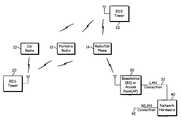
- FIG. 1is a schematic block diagram illustrating a broadcast system that includes a plurality of broadcast radio towers 20 , 22 and a plurality of radio devices 10 , 12 and 14 in accordance with the present invention.
- Each of the broadcast radio towers 20 , 22may be a Radio Data System (RDS) tower, as shown, or a non-RDS tower.
- RDSRadio Data System
- the radio devicesmay be, for example, car radios 20 , portable radios 12 , cellular telephones incorporating radio receivers (radio/cell phone) 14 and/or other wireless devices that include radio receivers.
- Each of the radio devices 10 , 12 and 14is operable to receive a plurality of broadcast radio signals broadcast from one or more of the broadcast radio towers 20 , 22 .
- the broadcast radio signalsare frequency modulated (FM) signals.
- FMfrequency modulated
- the broadcast radio signalsmay use modulations different than FM.
- Each of the FM broadcast radio signalsis used by the radio devices 10 , 12 and 14 to determine call station identification information identifying the broadcast radio towers 20 , 22 that are broadcasting the broadcast radio signals.
- each of the FM broadcast radio signalsincludes radio data system (RDS) data that identifies, among other things, the call station identity (e.g., call sign or station name) of the RDS broadcast tower 20 , 22 transmitting the FM broadcast radio signal.
- RDSradio data system
- the call station identification informationcan be included in another form of station broadcast or inferred based upon the approximate location of the radio device 10 , 12 and 14 and reception at certain frequencies. For example, upon receiving appreciable signal strength at 95.5 MHz FM in Orange County, Calif., the radio device 10 , 12 , 14 is able to discern that the call station identity is “KLOS.”
- the Radio Data Systemis a standard from the European Broadcasting Union for sending small amount of digital information using conventional FM radio broadcasts.
- RBDSRadio Broadcast Data System
- the term RDSincludes both the European RDS standard and the U.S. RBDS standard.
- FM radio stationsare allocated 200 kHz of bandwidth (in Europe, it is 100 kHz).
- RDSis a separate radio signal (subcarrier) that fits within the station's frequency allocation.
- the RDS subcarriercarries digital information at a frequency of 57 kHz with a data rate of 1187.5 bits per second.
- the RDS datais transmitted simultaneously with the standard FM stereo (or monophonic) radio broadcast.
- the RDSoperates by adding data to the baseband signal that is used to modulate the radio frequency carrier.
- the baseband signalconsists of a mono audio component including the combination of the left and right stereo speaker components that is transmitted at the normal audio frequencies up to 15 kHz, a stereo difference signal subcarrier that is amplitude modulated as a double sideband suppressed carrier signal at 38 kHz and a pilot tone at 19 kHz that is used to enable the radio receiver demodulator to recreate the 38 kHz subcarrier to decode the stereo difference signal.
- the stereo difference signalis above the audio hearing range, and therefore, does not detract from the normal mono signal.
- the RDS datais placed above the stereo difference signal on a 57 kHz RDS subcarrier that is locked onto the pilot tone.
- the RDS subcarrieris phase modulated, typically using a form of modulation called Quadrature Phase Shift Keying (QPSK).
- QPSKQuadrature Phase Shift Keying
- the radio device 10 , 12 , 14receives an FM broadcast signal from a particular RDS broadcast tower 20 or 22 that is broadcasting at that carrier frequency. If the received FM broadcast signal includes RDS data, the radio device 10 , 12 , 14 demodulates the RDS data to identify the station that the receiver is tuned to. The call station identity is often displayed on a display of the radio device 10 , 12 , 14 to enable the user to visually identify the station.
- an RDS-enabled receiveris currently tuned to a carrier frequency including RDS data identifying a particular radio station with a call sign of “KMMM” and a station name of “The Music,” the display on the radio device 10 , 12 , 14 can display not only the carrier frequency, but also the call sign and the station name.
- the call station identification information included within the broadcast RDS data or otherwise determined from the broadcast radio signalcan further assist in positioning the radio device 10 , 12 , 14 within the broadcast system.
- the geographical (physical) location of each of the broadcast radio towers 20 , 22is fixed. Therefore, with knowledge of the geographical coordinates (latitude and longitude) of the tower 20 , 22 from which a particular FM radio signal is broadcast, the location of a particular radio device 10 , 12 , 14 can be determined.
- coordinate data identifying the geographical coordinates of one or more broadcast radio towers 20 , 22can be cross-referenced with station identification information included in the RDS data of, or otherwise determined from, a received FM radio signal to identify the broadcast radio tower (e.g., tower 20 ) broadcasting the received FM radio signal and the geographical coordinates of that broadcasting tower 20 .
- the location of the radio devicee.g., device 10
- the transmit power of the broadcasting tower 20is compared to the signal strength of the received broadcast FM radio signal to calculate the location of the radio device 10 .
- the measured signal strengthcan be considered to be inversely proportional to the distance between the radio device 10 and the tower 10 .
- Taking measurements from multiple towers 20 , 22can improve the accuracy of the radio device 10 location. For example, using signal strength measurements from a single tower merely positions the radio device 10 to a radial distance between the radio device 10 and the tower (i.e., the radio device 10 is located at any point along the circumference of a circular area surrounding the tower, in which the circular area has a radius equal to the distance between the radio device and the tower). Using signal strength measurements from two towers positions the radio device 10 to one of two points where the circumferences of the two circular areas overlap. However, using signal strength measurements from three or more towers enables the use of a triangulation technique that pinpoints the location of the radio device. Accuracy can be further improved by time averaging multiple measurements taken of each received radio signal.
- signal strength locating algorithmsexist. For example, when the tower 20 , 22 is far away from the mobile device 10 , the position accuracy predicted from that measurement is typically less than when the tower 20 , 22 is closer. Therefore, measurements taken from towers 20 , 22 with shorter distances to the radio device 10 can be weighted more heavily than measurements taken from towers 20 , 22 that are further away from the radio device 10 . As another example, if only one or two broadcast towers in the area have an RDS broadcast capability or are otherwise capable of providing call station identification information to the radio device 10 , the radio device 10 can approximate its location with the one or two RDS signals, and then resolve the remaining uncertainty using the signal strength of other non-RDS broadcast stations.
- the broadcast systemfurther includes various components of a wireless communication system for communicating with the cellular telephone component of the combined radio/cell phone 14 (hereinafter referred to for simplicity as the “cellular telephone”).
- a wireless communication systemmay include a base station or access point (AP) 30 and a network hardware component 40 .
- the base station or AP 30is coupled to the network hardware component 40 via local area network (LAN) connection 32 .
- the network hardware component 40which may be a router, switch, bridge, modem, system controller, etc., provides a wide area network connection 42 for the wireless communication system.
- the base station or access point 30has an associated antenna or antenna array to communicate with the cellular telephone.
- the cellular telephoneregisters with the base station or access point 30 to receive services from the wireless communication system.
- the cellular telephonecommunicates directly via an allocated channel.
- base stationsare used for cellular telephone systems and similar systems, while access points are used for in-home or in-building wireless networks.
- access pointsare typically used in Bluetooth systems.
- the cellular telephone and the base station or access point 30each include a built-in transceiver (transmitter and receiver) for modulating/demodulating information (data or speech) bits into a format that comports with the type of wireless communication system.
- wireless communication standardse.g., IEEE 802.11, Bluetooth, advanced mobile phone services (AMPS), digital AMPS, global system for mobile communications (GSM), code division multiple access (CDMA), local multi-point distribution systems (LMDS), multi-channel-multi-point distribution systems (MMDS), and/or variations thereof
- GSMglobal system for mobile communications
- CDMAcode division multiple access
- LMDSlocal multi-point distribution systems
- MMDSmulti-channel-multi-point distribution systems
- the cellular telephone component of the radio/cell phone 14can facilitate the positioning of the radio/cell phone 14 .
- the network hardware component 40may provide RDS tower geographical coordinate information to the cellular telephone.
- the network hardware component 40may provide approximate locations or areas, along with various frequencies and associated call station identification information for towers within the location/area.
- the cellular telephoneUpon receiving the downloaded data, the cellular telephone can store the data in a non-volatile memory within the radio/cell phone 14 for use in a subsequent positioning of the radio/cell phone 14 in the broadcast system.
- the cellular telephonecan provide the collected signal strength measurements to the internal transceiver within the cellular telephone to communicate the signal strength measurements to the network hardware component 40 using any available wireless communication standard (e.g., IEEE 802.11x, Bluetooth, et cetera).
- the network hardware component 40can process the signal strength measurements and/or forward the signal strength measurements to another network device to determine the location of the radio/cell phone 14 within the broadcast network.
- FIG. 2is a schematic block diagram an exemplary radio device 10 , 12 , 14 in accordance with the present invention.
- the radio device 10 , 12 , 14includes an antenna 50 , a radio receiver 52 , processing circuitry 60 and a memory 62 .
- the radio device 10 , 12 , 14may further include an optional network transceiver 92 and associated antenna 90 for communicating with a wireless (cellular) communication network and/or an optional Global Positioning System (GPS) receiver 80 that is capable of positioning the radio device 10 , 12 , 14 using a GPS technique.
- GPSGlobal Positioning System
- the transceiver 92may be built-in or an externally coupled component.
- the processing circuitry 60is communicatively coupled to the memory 62 .
- the memory 62stores, and the processing circuitry 60 executes, operational instructions corresponding to at least some of the functions illustrated herein.
- the memory 62maintains a locating module 63 , Radio Data System (RDS) data 64 (e.g., broadcast RDS data received by the radio device 10 , 12 , 14 ), a measurement module 65 , signal quality characteristics 66 (e.g., signal strength measurements), RDS position data 67 (e.g., coordinate data associated with RDS broadcast towers), one or more RDS identifiers 68 (e.g., call station identification information containing call signs and/or names of one or more radio stations) and location information 69 (e.g., one or more locations of the radio device 10 , 12 , 14 ).
- RDSRadio Data System
- the measurement module 65includes instructions executable by the processing circuitry 60 for measuring signal quality characteristics associated with one or more received broadcast FM radio signals.
- the locating module 63includes instructions executable by the processing circuitry 60 for calculating the current location of the radio device 10 , 12 , 14 .
- the measurement module 65 and locating module 63each provide respective instructions to the processing circuitry 60 during positioning of the radio device 10 , 12 , 14 .
- the processing circuitry 60may be implemented using a shared processing device, individual processing devices, or a plurality of processing devices.
- a processing devicemay be a microprocessor, micro-controller, digital signal processor, microcomputer, central processing unit, field programmable gate array, programmable logic device, state machine, logic circuitry, analog circuitry, digital circuitry, and/or any device that manipulates signals (analog and/or digital) based on operational instructions.
- the memory 62may be a single memory device or a plurality of memory devices.
- Such a memory devicemay be a read-only memory, random access memory, volatile memory, non-volatile memory, static memory, dynamic memory, flash memory, and/or any device that stores digital information.
- the processing circuitry 60implements one or more of its functions via a state machine, analog circuitry, digital circuitry, and/or logic circuitry
- the memory storing the corresponding operational instructionsis embedded with the circuitry comprising the state machine, analog circuitry, digital circuitry, and/or logic circuitry.
- the radio device of FIG. 2may be implemented using one or more integrated circuits.
- the radio receiver 52may be implemented on a first integrated circuit, while the processing circuitry 60 is implemented on a second integrated circuit, and the remaining components, i.e., the network transceiver 92 and GPS receiver 80 may be implemented on a third integrated circuit.
- the radio receiver 52 and network transceiver 92may be implemented on a single integrated circuit.
- the radio receiver 52 and processing circuitry 60may be implemented on a single integrated circuit.
- memory 62may be implemented on the same integrated circuit as processing circuitry 60 or on a different integrated circuit.
- the radio device 10 , 12 , 14further includes an input interface 70 and an output interface 72 , each communicatively coupled to the processing circuitry 60 .
- the output interface 72provides an interface to one or more output devices, such as a display, speakers, etc.
- the input interface 70provides one or more interfaces for receiving user input via one or more input devices (e.g., mouse, keyboard, etc.) from a user operating the radio device 10 , 12 , 14 .
- input devicese.g., mouse, keyboard, etc.
- such user inputcan include a request to position the radio device 10 , 12 , 14 .
- the radio device 10 , 12 , 14receives a broadcast FM radio signal via the antenna 50 , which was broadcast by an RDS tower.
- the antenna 50provides the FM radio signal to the radio receiver 52 , where the receiver 52 processes the FM radio signal to demodulate the received FM radio signal and recover the stereo audio signals (left and right speaker audio signals).
- the receiver 52processes the FM radio signal to demodulate the received FM radio signal and recover the stereo audio signals (left and right speaker audio signals).
- the audio signals for the left and right speakersare added to produce the mono audio signal and subtracted from one another to produce the stereo difference signal.
- the receiver 52is a stereo receiver
- the receiver 52includes an FM demodulator to demodulate the mono audio signal and an additional stereo demodulator to demodulate the stereo difference signal.
- the radio receiver 52Since the stereo difference signal is phase locked to the 19 kHz pilot tone included in the received FM radio signal, the pilot tone is used to control the frequency and phase of a 38 kHz oscillator in the stereo demodulator of the radio receiver 52 .
- the radio receiver 52is able to demodulate both the mono audio signal and stereo difference signal and then combine the two demodulated signals to recover the original left and right stereo audio signals.
- the radio receiver 52further includes an RDS demodulator that operates to decode the RDS data 64 included within the received FM radio signal.
- the original RDS datais transmitted by the RDS tower at a data rate of 1187.5 bits per second, which is equal to the frequency of the RDS subcarrier divided by 48. This data rate allows the RDS demodulator to operate synchronously, which reduces problems with spurious signals in the demodulator.
- the RDS datais transmitted in groups consisting of four blocks. Each block contains a 16 bit information word and a 10 bit check word. The 10 bit check word enables the RDS demodulator to detect and correct errors and also provides a method for synchronization. With a data rate of 1187.5 bits per second, approximately 11.4 groups can be transmitted each second.
- the data groupsare structured so that different data can be transmitted as efficiently as possible.
- the coding structureis such that messages that require frequent repeating normally occupy the same position within the groups.
- the first block in a groupnormally contains the program identification (PI) code (e.g., the station identity).
- PIprogram identification
- the RDS demodulatoris able to demodulate the first block in a received data group to determine the RDS station identifier of the RDS tower that broadcasted the received data group.
- the decoded RDS data 64 including the RDS station identifier 68is provided to the processing circuitry 60 for storage within the memory 62 .
- the decoded RDS data 64 including the RDS station identifier 68can be provided to the output I/F 72 for display on the radio device 10 , 12 , 14 .
- the RDS station identifier 68can also be used to position the radio device 10 , 12 , 14 within the broadcast system.
- the measurement module 65provides instructions to the processing circuitry 60 to obtain signal quality characteristic measurements 66 of one or more received broadcast FM radio signals.
- a single signal quality characteristic measurement for each received radio signalcan be obtained or multiple signal quality characteristic measurements for each received radio signal can be averaged over time to improve the accuracy of the characterization.
- a radio signalthere are several characteristics of a radio signal that can be used to determine the location of its source.
- One characteristicis the signal strength of the received signal.
- the received power (average amplitude) of a radio signaldecays exponentially relative to the distance between the source of the signal and the point of reception. Therefore, by measuring the signal strength of a received signal transmitted from a known RDS tower location with a known transmit power, the signal strength measurements can be used to determine the distance between the radio device 10 , 12 , 14 and the broadcasting RDS tower.
- Another characteristicis the signal to noise (SNR) ratio of the received signal.
- the numerator of the SNR ratiois the signal power of the received radio signal, while the denominator of the SNR ratio is the noise power of the received radio signal.
- the signal quality characteristic measurements 66can either be provided to a network device via the network transceiver 92 for calculation of the location of the radio device 10 , 12 , 14 by the network device or used internally by the radio device 10 , 12 , 14 in determining its own location.
- both the signal quality characteristic measurements 66 and the RDS data 64 identifying the source of the radio signals associated with the signal quality characteristic measurementsare transmitted to the network device.
- the radio device 10 , 12 , 14in order to calculate its own location, the radio device 10 , 12 , 14 must have knowledge of the geographical (physical) location of the RDS tower from which a particular FM radio signal is broadcast. Therefore, RDS position data 67 identifying the geographical coordinates and associated transmit powers of one or more RDS towers are stored in the memory 62 .
- the RDS position data 67is pre-determined and maintained within the memory 62 of the radio device 10 , 12 , 14 .
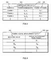
- the RDS position data 67can be maintained as a table 300 of tower position data that includes the identifier 310 (e.g., PI code) of the RDS tower, the geographical coordinates 320 of the RDS tower (x, y) and the transmit power 330 of the RDS tower.
- the RDS position data 67 associated with a particular received broadcast radio signalis included within the RDS data 64 that is broadcast by the RDS tower.
- the RDS position data 67is downloaded from a network device via the network transceiver 92 . Therefore, upon receipt of instructions from the measurement module 65 , the processing circuitry 60 compares the RDS station identifier 68 included in the RDS data 64 of a received FM radio signal with the stored RDS position data 67 to identify the RDS tower broadcasting the received FM radio signal, the geographical coordinates of that broadcasting RDS tower and the transmit power of that RDS tower.
- the locating module 62provides instructions to the processing circuitry 60 to calculate the location of the radio device 10 , 12 , 14 using any available locating algorithm. In an exemplary embodiment, the locating module 62 provides instructions to the processing circuitry 60 to compare the transmit power of a particular broadcasting RDS tower to the measured signal strength or measured SNR of the received broadcast FM radio signal to determine the distance between that particular RDS tower and the radio device 10 , 12 , 14 .
- the locating module 62can provide instructions to the processing circuitry 60 to use all received RDS FM radio signals or only a certain number of received RDS FM radio signals or to weight the received RDS FM radio signals based on the signal quality of the received RDS FM radio signals, distance between the RDS towers and the radio device, knowledge of “good” RDS towers from received data or history and/or observed signal characterization over time to determine which RDS towers provide consistent signal quality.
- the exponential decay of the received signal as determined by the difference between the measured signal strength and the transmit poweris used by the processing circuitry 60 to calculate an estimated distance between the radio device 10 and the RDS tower.
- the RDS position data 67further includes distance information identifying the distance between the radio device 10 and the RDS tower 10 as a function of the measured signal strength.
- the RDS position data 67can further include a respective table 400 of signal measurement data for each RDS tower that includes the measured signal strength (M 1 -M M ) and the associated radial distance (R) from the RDS tower (R 1 -R M ).
- the signal quality characteristic measurementscan be mapped to the table 400 to determine a best fit.
- the network devicecan maintain the table 400 and apply the signal quality characteristic measurements 66 provided by the radio device 10 to the table 400 to determine the best fit.
- the signal strength RDS position data 67is pre-determined and maintained within the memory 62 .
- the radio device 10 , 12 , 14can include the GPS receiver 80 to determine the location of the test radio device with each signal measurement, thereby populating the table 400 shown in FIG. 4 for later use by the radio device 10 .
- the GPS receiver 80may also be included within a test radio device to populate the table and download it to other radio devices.
- the signal measurement RDS position data 67 associated with a particular received broadcast radio signalis included within the RDS data 64 that is broadcast by the RDS tower.
- the signal measurement RDS position data 67is downloaded from a network device via the network transceiver 92 .
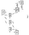
- FIG. 5shows a broadcast system having three RDS towers, RDS Tower 1 , RDS Tower 2 and RDS Tower 3 , each at a known location.
- RDS Tower 1is located at geographical coordinates x 1 , y 1
- RDS Tower 2is located at geographical coordinates x 2
- y 2and RDS Tower 3 is located at geographical coordinates x 3 , y 3 .
- a car having an RDS-capable car radio 10is traveling within the broadcast system. To determine the location (x c , y c ) of the car, the car radio 10 measures the signal quality characteristics of FM radio signals broadcast from RDS Tower 1 , RDS Tower 2 and RDS Tower 3 .
- the signal quality characteristic measurements from each RDS towerenable the car radio 10 to position itself along a circumference of respective circular areas surrounding each RDS tower, in which each area has a radius equal to the distance between the car radio 10 and the respective RDS tower. For example, based on the signal quality characteristic measurements taken by the car radio of the radio signal broadcast from RDS Tower 1 , the geographical location of RDS Tower 1 and the transmit power of RDS Tower 1 , the car radio 10 can determine the radial distance R 1 between the car radio 10 and RDS Tower 1 . Thus, the car radio 10 is able to discern that its location is at any point along the circumference of a circular area surrounding RDS Tower 1 , in which the circular area has a radius R 1 equal to the distance between the radio device and the RDS tower. Using signal strength measurements from two RDS towers, e.g., RDS Tower 1 and RDS Tower 2 positions the car radio 10 to one of two points A or B where the circumferences of the two circular areas overlap.
- RDS Tower 1e.g., RDS Tower 1 , RDS Tower 2 and RDS Tower 3
- Triangulation of the location of the car radio 10can be improved using more than three RDS Towers.
- N RDS TowersN circles can be created based on the signal strength measurements taken from each of the N Towers, and the location of the car radio 10 can be identified as the point (geographical position) that is closest to the intersection of all of the N circles.
- the signal strength measurements taken from the RDS Tower(s)can be used to determine a “course” location of the car radio 10 . Thereafter, using signal strength measurements taken from non-RDS Towers enables the car radio 10 to test remaining possible locations (e.g., when using measurements from both RDS Tower 1 and RDS Tower 2 , the possible locations include points A or B), and pick the one that best fits the non-RDS measurement data.
- FIG. 6is a logic diagram of a method 600 for positioning a radio device using FM broadcast radio signals in accordance with the present invention.
- the processbegins at step 610 , where the radio device monitors and stores RDS tower identifiers (e.g., PI codes or other station identification information) of all of the RDS FM radio signals (i.e., all RDS sources) within range of the radio device.
- the processcontinues at step 620 , where the radio device measures the signal quality characteristics of broadcast FM radio signals received from at least three RDS sources (or from non-RDS sources if only one or two RDS sources are in the area).
- the radio devicedetermines RDS position data for each measured RDS source based on the received RDS tower identifiers. For example, the radio device can access a table containing RDS tower identifiers, associated geographical RDS tower coordinates and associated RDS tower transmit powers.
- the radio devicecalculates its location using the measured signal quality characteristics and the RDS position data from the RDS sources. For example, in one embodiment, the radio device can compare the transmit power of a particular broadcasting RDS tower to the measured signal strength or measured SNR of the received broadcast FM radio signal to determine the distance between that particular RDS tower and the radio device. In another embodiment, the radio device can compare the measured signal strength to a table containing signal strength measurements and associated radial distances (R) for a particular RDS tower. Using signal quality characteristic measurements of received FM radio signals broadcast from three or more different RDS towers enables the location of the radio device to be triangulated.
- Rradial distances
- the terms “substantially” and “approximately”provides an industry-accepted tolerance for its corresponding term and/or relativity between items. Such an industry-accepted tolerance ranges from less than one percent to fifty percent and corresponds to, but is not limited to, component values, integrated circuit process variations, temperature variations, rise and fall times, and/or thermal noise. Such relativity between items ranges from a difference of a few percent to magnitude differences.
- the term(s) “coupled to” and/or “coupling” and/orincludes direct coupling between items and/or indirect coupling between items via an intervening item (e.g., an item includes, but is not limited to, a component, an element, a circuit, and/or a module) where, for indirect coupling, the intervening item does not modify the information of a signal but may adjust its current level, voltage level, and/or power level.
- an intervening iteme.g., an item includes, but is not limited to, a component, an element, a circuit, and/or a module
- inferred couplingi.e., where one element is coupled to another element by inference
- the term “operable to”indicates that an item includes one or more of power connections, input(s), output(s), etc., to perform one or more its corresponding functions and may further include inferred coupling to one or more other items.
- the term “associated with”,includes direct and/or indirect coupling of separate items and/or one item being embedded within another item.
Landscapes
- Engineering & Computer Science (AREA)
- Physics & Mathematics (AREA)
- General Physics & Mathematics (AREA)
- Radar, Positioning & Navigation (AREA)
- Remote Sensing (AREA)
- Signal Processing (AREA)
- Position Fixing By Use Of Radio Waves (AREA)
Abstract
Description
Claims (25)
Priority Applications (3)
| Application Number | Priority Date | Filing Date | Title |
|---|---|---|---|
| US11/761,450US7941159B2 (en) | 2007-05-25 | 2007-06-12 | Position determination using received broadcast signals |
| US12/026,632US20080291086A1 (en) | 2007-05-25 | 2008-02-06 | Position determination using available positioning techniques |
| US12/905,159US8078194B2 (en) | 2007-05-25 | 2010-10-15 | Position determination using received broadcast signals |
Applications Claiming Priority (2)
| Application Number | Priority Date | Filing Date | Title |
|---|---|---|---|
| US93191807P | 2007-05-25 | 2007-05-25 | |
| US11/761,450US7941159B2 (en) | 2007-05-25 | 2007-06-12 | Position determination using received broadcast signals |
Related Child Applications (2)
| Application Number | Title | Priority Date | Filing Date |
|---|---|---|---|
| US12/026,632Continuation-In-PartUS20080291086A1 (en) | 2007-05-25 | 2008-02-06 | Position determination using available positioning techniques |
| US12/905,159ContinuationUS8078194B2 (en) | 2007-05-25 | 2010-10-15 | Position determination using received broadcast signals |
Publications (2)
| Publication Number | Publication Date |
|---|---|
| US20080311870A1 US20080311870A1 (en) | 2008-12-18 |
| US7941159B2true US7941159B2 (en) | 2011-05-10 |
Family
ID=40132800
Family Applications (2)
| Application Number | Title | Priority Date | Filing Date |
|---|---|---|---|
| US11/761,450Expired - Fee RelatedUS7941159B2 (en) | 2007-05-25 | 2007-06-12 | Position determination using received broadcast signals |
| US12/905,159Expired - Fee RelatedUS8078194B2 (en) | 2007-05-25 | 2010-10-15 | Position determination using received broadcast signals |
Family Applications After (1)
| Application Number | Title | Priority Date | Filing Date |
|---|---|---|---|
| US12/905,159Expired - Fee RelatedUS8078194B2 (en) | 2007-05-25 | 2010-10-15 | Position determination using received broadcast signals |
Country Status (1)
| Country | Link |
|---|---|
| US (2) | US7941159B2 (en) |
Cited By (11)
| Publication number | Priority date | Publication date | Assignee | Title |
|---|---|---|---|---|
| US20100017116A1 (en)* | 2008-07-15 | 2010-01-21 | Htc Corporation | Positioning method, positioning apparatus, and recording medium |
| US20100128637A1 (en)* | 2008-11-21 | 2010-05-27 | Qualcomm Incorporated | Network-centric determination of node processing delay |
| US20100130230A1 (en)* | 2008-11-21 | 2010-05-27 | Qualcomm Incorporated | Beacon sectoring for position determination |
| US20100130229A1 (en)* | 2008-11-21 | 2010-05-27 | Qualcomm Incorporated | Wireless-based positioning adjustments using a motion sensor |
| US20100128617A1 (en)* | 2008-11-25 | 2010-05-27 | Qualcomm Incorporated | Method and apparatus for two-way ranging |
| US20100273418A1 (en)* | 2008-11-06 | 2010-10-28 | Qualcomm Incorporated | Static nodes positioning in a wireless network |
| US20130237246A1 (en)* | 2008-11-21 | 2013-09-12 | Qualcomm Incorporated | Wireless signal model updating using determined distances |
| US9002349B2 (en) | 2008-12-22 | 2015-04-07 | Qualcomm Incorporated | Post-deployment calibration for wireless position determination |
| US20150168533A1 (en)* | 2013-12-16 | 2015-06-18 | Inventec Appliances (Pudong) Corporation | System for memorizing object location and method thereof |
| US9137681B2 (en) | 2010-04-30 | 2015-09-15 | Qualcomm Incorporated | Device for round trip time measurements |
| US10082399B2 (en) | 2013-06-14 | 2018-09-25 | HangZhou HaiCun Information Technology Co., Ltd. | Music-based positioning aided by dead reckoning |
Families Citing this family (36)
| Publication number | Priority date | Publication date | Assignee | Title |
|---|---|---|---|---|
| US8934416B2 (en)* | 2005-03-09 | 2015-01-13 | Xirrus, Inc. | System for allocating channels in a multi-radio wireless LAN array |
| US10091616B2 (en) | 2005-12-15 | 2018-10-02 | Polte Corporation | Angle of arrival (AOA) positioning method and system for positional finding and tracking objects using reduced attenuation RF technology |
| US10834531B2 (en)* | 2005-12-15 | 2020-11-10 | Polte Corporation | Multi-path mitigation in rangefinding and tracking objects using reduced attenuation RF technology |
| US9813867B2 (en) | 2005-12-15 | 2017-11-07 | Polte Corporation | Angle of arrival (AOA) positioning method and system for positional finding and tracking objects using reduced attenuation RF technology |
| US9699607B2 (en) | 2005-12-15 | 2017-07-04 | Polte Corporation | Multi-path mitigation in rangefinding and tracking objects using reduced attenuation RF technology |
| US9913244B2 (en)* | 2005-12-15 | 2018-03-06 | Polte Corporation | Partially synchronized multilateration or trilateration method and system for positional finding using RF |
| US10281557B2 (en) | 2005-12-15 | 2019-05-07 | Polte Corporation | Partially synchronized multilateration/trilateration method and system for positional finding using RF |
| US9507007B2 (en) | 2005-12-15 | 2016-11-29 | Polte Corporation | Multi-path mitigation in rangefinding and tracking objects using reduced attenuation RF technology |
| US9288623B2 (en)* | 2005-12-15 | 2016-03-15 | Invisitrack, Inc. | Multi-path mitigation in rangefinding and tracking objects using reduced attenuation RF technology |
| US7612712B2 (en) | 2006-04-25 | 2009-11-03 | Rx Networks Inc. | Distributed orbit modeling and propagation method for a predicted and real-time assisted GPS system |
| US8125382B2 (en)* | 2006-04-25 | 2012-02-28 | Rx Networks Inc. | Autonomous orbit propagation system and method |
| US9088907B2 (en)* | 2007-06-18 | 2015-07-21 | Xirrus, Inc. | Node fault identification in wireless LAN access points |
| US7990314B2 (en)* | 2008-06-30 | 2011-08-02 | Liao Henry H | Method and system for locating a geographical position using broadcast frequency modulation signals |
| US8519884B2 (en)* | 2008-07-29 | 2013-08-27 | Aruba Networks, Inc. | Distance estimation |
| US8482478B2 (en)* | 2008-11-12 | 2013-07-09 | Xirrus, Inc. | MIMO antenna system |
| US8896431B2 (en)* | 2009-12-21 | 2014-11-25 | Continental Automotive Systems, Inc. | Apparatus and method for compromised vehicle tracking |
| NL2005776C2 (en)* | 2010-11-29 | 2012-05-30 | Nedap Nv | ELECTRONIC LOCALIZING SYSTEM. |
| US8892061B2 (en)* | 2011-03-24 | 2014-11-18 | At&T Intellectual Property I, L.P. | Methods, devices, and computer program products for tracking receipt and determining effectiveness of radio broadcast signals |
| US8830854B2 (en) | 2011-07-28 | 2014-09-09 | Xirrus, Inc. | System and method for managing parallel processing of network packets in a wireless access device |
| US11125850B2 (en) | 2011-08-03 | 2021-09-21 | Polte Corporation | Systems and methods for determining a timing offset of emitter antennas in a wireless network |
| US11835639B2 (en) | 2011-08-03 | 2023-12-05 | Qualcomm Technologies, Inc. | Partially synchronized multilateration or trilateration method and system for positional finding using RF |
| US8868002B2 (en) | 2011-08-31 | 2014-10-21 | Xirrus, Inc. | System and method for conducting wireless site surveys |
| US9055450B2 (en) | 2011-09-23 | 2015-06-09 | Xirrus, Inc. | System and method for determining the location of a station in a wireless environment |
| CN102494650A (en)* | 2011-11-29 | 2012-06-13 | 航天科工深圳(集团)有限公司 | Pole tower displacement monitoring system and monitoring method thereof |
| US8548497B2 (en)* | 2011-12-16 | 2013-10-01 | Microsoft Corporation | Indoor localization using commercial frequency-modulated signals |
| US10863313B2 (en) | 2014-08-01 | 2020-12-08 | Polte Corporation | Network architecture and methods for location services |
| US10440512B2 (en) | 2012-08-03 | 2019-10-08 | Polte Corporation | Angle of arrival (AOA) positioning method and system for positional finding and tracking objects using reduced attenuation RF technology |
| US10845453B2 (en) | 2012-08-03 | 2020-11-24 | Polte Corporation | Network architecture and methods for location services |
| WO2016166691A1 (en)* | 2015-04-14 | 2016-10-20 | Poynting Antennas (Pty) Limited | Electronic apparatus for use in rendering broadcast media carrying signals |
| TWI607659B (en)* | 2016-03-31 | 2017-12-01 | 亞碩綠能股份有限公司 | Miltipoint wireless communication system and control method thereof |
| US10966077B2 (en)* | 2017-09-29 | 2021-03-30 | Schlage Lock Company Llc | Communicating emergency information via a beacon |
| CN107528629B (en)* | 2017-09-30 | 2024-01-30 | 湖南迈克森伟电子科技有限公司 | Satellite measurement and control data transmission broadcast integrated communication system |
| US11255945B2 (en)* | 2018-03-27 | 2022-02-22 | Polte Corporation | Multi-path mitigation in tracking objects using compressed RF data |
| US20200322681A1 (en)* | 2019-04-08 | 2020-10-08 | Edge Networks, Inc. | Congestion Aware Hybrid File Transfer |
| US20220295219A1 (en)* | 2021-03-15 | 2022-09-15 | Samsung Electronics Co., Ltd. | Method and apparatus for collaborative wi-fi localization |
| CN114885280A (en)* | 2022-05-06 | 2022-08-09 | 东软睿驰汽车技术(大连)有限公司 | Positioning method and device based on FM signal, electronic equipment and storage medium |
Citations (26)
| Publication number | Priority date | Publication date | Assignee | Title |
|---|---|---|---|---|
| US5365450A (en) | 1992-12-17 | 1994-11-15 | Stanford Telecommunications, Inc. | Hybrid GPS/data line unit for rapid, precise, and robust position determination |
| US5465088A (en) | 1992-03-13 | 1995-11-07 | Robert Bosch Gmbh | Receiver for traffic messages |
| JP2000137065A (en) | 1998-10-30 | 2000-05-16 | Nec Corp | Laser ray detecting device |
| US6081780A (en) | 1998-04-28 | 2000-06-27 | International Business Machines Corporation | TTS and prosody based authoring system |
| US6107939A (en) | 1998-11-05 | 2000-08-22 | Trimble Navigation Limited | Lane change alarm for use in a highway vehicle |
| US6211817B1 (en) | 1999-07-27 | 2001-04-03 | Trimble Navigation Limited | Differential global positioning system using almanac data for a fast time to first fix |
| US6219385B1 (en) | 1998-12-23 | 2001-04-17 | Itt Manufacturing Enterprises, Inc. | Digital AM/FM positioning system (DAFPS)—an international positioning system |
| US6370475B1 (en) | 1997-10-22 | 2002-04-09 | Intelligent Technologies International Inc. | Accident avoidance system |
| US20020101374A1 (en) | 2001-01-29 | 2002-08-01 | Katsuhiko Mutoh | Navigation system, GPS terminal and navigation method using supplementary data in broadcast radio wave signal |
| US20030122711A1 (en) | 2001-12-31 | 2003-07-03 | Panasik Carl M. | Electronic device precision location via local broadcast signals |
| US20030144007A1 (en)* | 2002-01-25 | 2003-07-31 | Mikael Johansson | Methods, systems, and computer program products for determining the location of a mobile terminal based on the strengths of signals received from transmitters having known locations |
| US6704650B1 (en) | 2000-05-31 | 2004-03-09 | Skynetix, Llc | Technique for accurate distance and velocity calculations using the global positioning system (GPS) |
| US20040119638A1 (en) | 2002-09-25 | 2004-06-24 | Fagan John E. | Navigation system using locally augmented GPS |
| US20040198279A1 (en) | 2002-12-16 | 2004-10-07 | Nokia Corporation | Broadcast media bookmarks |
| US20040220722A1 (en) | 2003-05-01 | 2004-11-04 | Honeywell International Inc. | Radio navigation system |
| US20050184905A1 (en) | 2004-01-23 | 2005-08-25 | Michio Kobayashi | Positioning device, mobile terminal, positioning method, and positioning program |
| US20050206559A1 (en) | 2004-03-16 | 2005-09-22 | Diggelen Frank Van | Method and apparatus for determining absolute time-of-day in a mobile-assisted satellite positioning system |
| US20050227703A1 (en)* | 2004-03-30 | 2005-10-13 | Cheng Steven D | Method for using base station power measurements to detect position of mobile stations |
| US20070132639A1 (en) | 2005-12-09 | 2007-06-14 | Korneluk Jose E | Method and apparatus for determining an approximate position of a satellite positioning receiver |
| US20070201421A1 (en)* | 2005-12-09 | 2007-08-30 | Honeywell International, Inc. | Method and apparatus for location estimation |
| US7319877B2 (en)* | 2003-07-22 | 2008-01-15 | Microsoft Corporation | Methods for determining the approximate location of a device from ambient signals |
| US20080222705A1 (en)* | 2007-03-06 | 2008-09-11 | Capitol Broadcasting Company, Inc. | System and method for delivering geographically restricted content, such as over-air broadcast programming, to a recipient over a computer network, namely the internet |
| US20080238766A1 (en) | 2007-03-29 | 2008-10-02 | Morgan Patrick N | Apparatus having integrated radio and GPS receivers |
| US7495609B1 (en) | 2006-11-07 | 2009-02-24 | Eride, Inc. | Mobile GPS aiding data solution |
| US20090146870A1 (en) | 2007-12-06 | 2009-06-11 | Timothy Thome | System and method for wwan/wlan position estimation |
| US20100120422A1 (en)* | 2005-06-28 | 2010-05-13 | Microsoft Corporation | Positioning service utilizing existing radio base stations |
Family Cites Families (3)
| Publication number | Priority date | Publication date | Assignee | Title |
|---|---|---|---|---|
| US20040064251A1 (en)* | 2002-10-01 | 2004-04-01 | Miller Ronald Hugh | Telematics system with vehicle network |
| US7706975B2 (en)* | 2004-10-19 | 2010-04-27 | Qualcomm Incorporated | Mobile cellular identification database for enhanced GPS performance |
| US8364164B2 (en)* | 2006-08-11 | 2013-01-29 | Csr Technology Inc. | Cell ID based positioning from cell intersections |
- 2007
- 2007-06-12USUS11/761,450patent/US7941159B2/ennot_activeExpired - Fee Related
- 2010
- 2010-10-15USUS12/905,159patent/US8078194B2/ennot_activeExpired - Fee Related
Patent Citations (26)
| Publication number | Priority date | Publication date | Assignee | Title |
|---|---|---|---|---|
| US5465088A (en) | 1992-03-13 | 1995-11-07 | Robert Bosch Gmbh | Receiver for traffic messages |
| US5365450A (en) | 1992-12-17 | 1994-11-15 | Stanford Telecommunications, Inc. | Hybrid GPS/data line unit for rapid, precise, and robust position determination |
| US6370475B1 (en) | 1997-10-22 | 2002-04-09 | Intelligent Technologies International Inc. | Accident avoidance system |
| US6081780A (en) | 1998-04-28 | 2000-06-27 | International Business Machines Corporation | TTS and prosody based authoring system |
| JP2000137065A (en) | 1998-10-30 | 2000-05-16 | Nec Corp | Laser ray detecting device |
| US6107939A (en) | 1998-11-05 | 2000-08-22 | Trimble Navigation Limited | Lane change alarm for use in a highway vehicle |
| US6219385B1 (en) | 1998-12-23 | 2001-04-17 | Itt Manufacturing Enterprises, Inc. | Digital AM/FM positioning system (DAFPS)—an international positioning system |
| US6211817B1 (en) | 1999-07-27 | 2001-04-03 | Trimble Navigation Limited | Differential global positioning system using almanac data for a fast time to first fix |
| US6704650B1 (en) | 2000-05-31 | 2004-03-09 | Skynetix, Llc | Technique for accurate distance and velocity calculations using the global positioning system (GPS) |
| US20020101374A1 (en) | 2001-01-29 | 2002-08-01 | Katsuhiko Mutoh | Navigation system, GPS terminal and navigation method using supplementary data in broadcast radio wave signal |
| US20030122711A1 (en) | 2001-12-31 | 2003-07-03 | Panasik Carl M. | Electronic device precision location via local broadcast signals |
| US20030144007A1 (en)* | 2002-01-25 | 2003-07-31 | Mikael Johansson | Methods, systems, and computer program products for determining the location of a mobile terminal based on the strengths of signals received from transmitters having known locations |
| US20040119638A1 (en) | 2002-09-25 | 2004-06-24 | Fagan John E. | Navigation system using locally augmented GPS |
| US20040198279A1 (en) | 2002-12-16 | 2004-10-07 | Nokia Corporation | Broadcast media bookmarks |
| US20040220722A1 (en) | 2003-05-01 | 2004-11-04 | Honeywell International Inc. | Radio navigation system |
| US7319877B2 (en)* | 2003-07-22 | 2008-01-15 | Microsoft Corporation | Methods for determining the approximate location of a device from ambient signals |
| US20050184905A1 (en) | 2004-01-23 | 2005-08-25 | Michio Kobayashi | Positioning device, mobile terminal, positioning method, and positioning program |
| US20050206559A1 (en) | 2004-03-16 | 2005-09-22 | Diggelen Frank Van | Method and apparatus for determining absolute time-of-day in a mobile-assisted satellite positioning system |
| US20050227703A1 (en)* | 2004-03-30 | 2005-10-13 | Cheng Steven D | Method for using base station power measurements to detect position of mobile stations |
| US20100120422A1 (en)* | 2005-06-28 | 2010-05-13 | Microsoft Corporation | Positioning service utilizing existing radio base stations |
| US20070201421A1 (en)* | 2005-12-09 | 2007-08-30 | Honeywell International, Inc. | Method and apparatus for location estimation |
| US20070132639A1 (en) | 2005-12-09 | 2007-06-14 | Korneluk Jose E | Method and apparatus for determining an approximate position of a satellite positioning receiver |
| US7495609B1 (en) | 2006-11-07 | 2009-02-24 | Eride, Inc. | Mobile GPS aiding data solution |
| US20080222705A1 (en)* | 2007-03-06 | 2008-09-11 | Capitol Broadcasting Company, Inc. | System and method for delivering geographically restricted content, such as over-air broadcast programming, to a recipient over a computer network, namely the internet |
| US20080238766A1 (en) | 2007-03-29 | 2008-10-02 | Morgan Patrick N | Apparatus having integrated radio and GPS receivers |
| US20090146870A1 (en) | 2007-12-06 | 2009-06-11 | Timothy Thome | System and method for wwan/wlan position estimation |
Non-Patent Citations (1)
| Title |
|---|
| A. Youssef: Computing Location from Ambient FM Radio Signals; IEEE Wireless Communications and Networking Conference; vol. 2; p. 824-829; Mar. 2005. |
Cited By (21)
| Publication number | Priority date | Publication date | Assignee | Title |
|---|---|---|---|---|
| US20100017116A1 (en)* | 2008-07-15 | 2010-01-21 | Htc Corporation | Positioning method, positioning apparatus, and recording medium |
| US20100273418A1 (en)* | 2008-11-06 | 2010-10-28 | Qualcomm Incorporated | Static nodes positioning in a wireless network |
| US8639184B2 (en)* | 2008-11-06 | 2014-01-28 | Qualcomm Incorporated | Static nodes positioning in a wireless network |
| US9291704B2 (en) | 2008-11-21 | 2016-03-22 | Qualcomm Incorporated | Wireless-based positioning adjustments using a motion sensor |
| US9645225B2 (en) | 2008-11-21 | 2017-05-09 | Qualcomm Incorporated | Network-centric determination of node processing delay |
| US20100130229A1 (en)* | 2008-11-21 | 2010-05-27 | Qualcomm Incorporated | Wireless-based positioning adjustments using a motion sensor |
| US20130237246A1 (en)* | 2008-11-21 | 2013-09-12 | Qualcomm Incorporated | Wireless signal model updating using determined distances |
| US20100130230A1 (en)* | 2008-11-21 | 2010-05-27 | Qualcomm Incorporated | Beacon sectoring for position determination |
| US8892127B2 (en) | 2008-11-21 | 2014-11-18 | Qualcomm Incorporated | Wireless-based positioning adjustments using a motion sensor |
| US20100128637A1 (en)* | 2008-11-21 | 2010-05-27 | Qualcomm Incorporated | Network-centric determination of node processing delay |
| US9213082B2 (en) | 2008-11-21 | 2015-12-15 | Qualcomm Incorporated | Processing time determination for wireless position determination |
| US9125153B2 (en) | 2008-11-25 | 2015-09-01 | Qualcomm Incorporated | Method and apparatus for two-way ranging |
| US20100128617A1 (en)* | 2008-11-25 | 2010-05-27 | Qualcomm Incorporated | Method and apparatus for two-way ranging |
| US9002349B2 (en) | 2008-12-22 | 2015-04-07 | Qualcomm Incorporated | Post-deployment calibration for wireless position determination |
| US9137681B2 (en) | 2010-04-30 | 2015-09-15 | Qualcomm Incorporated | Device for round trip time measurements |
| US9247446B2 (en) | 2010-04-30 | 2016-01-26 | Qualcomm Incorporated | Mobile station use of round trip time measurements |
| US10082399B2 (en) | 2013-06-14 | 2018-09-25 | HangZhou HaiCun Information Technology Co., Ltd. | Music-based positioning aided by dead reckoning |
| US10704914B2 (en) | 2013-06-14 | 2020-07-07 | HangZhou HaiCun Information Technology Co., Ltd. | Positioning method using broadcast speeches |
| US10704913B2 (en) | 2013-06-14 | 2020-07-07 | HangZhou HaiCun Information Technology Co., Ltd. | Positioning method using music pieces |
| US20150168533A1 (en)* | 2013-12-16 | 2015-06-18 | Inventec Appliances (Pudong) Corporation | System for memorizing object location and method thereof |
| US9699613B2 (en)* | 2013-12-16 | 2017-07-04 | Inventec Appliances (Pudong) Corporation | System for memorizing object location and method thereof |
Also Published As
| Publication number | Publication date |
|---|---|
| US20080311870A1 (en) | 2008-12-18 |
| US20110034180A1 (en) | 2011-02-10 |
| US8078194B2 (en) | 2011-12-13 |
Similar Documents
| Publication | Publication Date | Title |
|---|---|---|
| US7941159B2 (en) | Position determination using received broadcast signals | |
| US20080284646A1 (en) | Use of broadcast position data for subsequent gps location fix | |
| US20080291086A1 (en) | Position determination using available positioning techniques | |
| US8428010B2 (en) | Location-based network detection | |
| US8755836B2 (en) | Method for searching the location of multi-SIM mobile terminal and an apparatus thereof | |
| US8040219B2 (en) | System and method for in-building location determination | |
| KR0153589B1 (en) | Cellular phone positioning system | |
| CN101208983B (en) | Methods, systems and devices for determining the location of a mobile device based on simulcast communication signals | |
| EP2618182B1 (en) | Location information providing device | |
| CN100362362C (en) | Use of global positioning satellites (GPS) to discover and select local services | |
| US20140347214A1 (en) | Method and system for gnss assistance data or lto data download over a broadcast band | |
| WO2006096923A1 (en) | Enhanced mobile location | |
| JP2000155163A (en) | Positioning system, method, and device | |
| CN101729977A (en) | Communication method, machine readable memory, communication system | |
| US6332070B1 (en) | Method and data receiver device for reception of a radio signal containing correction data for a global navigation satellite system | |
| US7068217B2 (en) | Positioning device, mobile terminal, positioning method, and positioning program | |
| KR20100016210A (en) | Location estimation in end-user devices using public radio signals | |
| JP2004061464A (en) | Position information terminal | |
| JPH11178042A (en) | Position detection system | |
| US20050079876A1 (en) | Method of location using signals of unknown origin | |
| GB2388749A (en) | Method and system for determining velocity of a mobile radiotelecommunications device including determining frequency difference due to doppler shift | |
| JP2001099909A (en) | Positioning information providing system | |
| US20210063521A1 (en) | Determining a position of a device with respect to another device | |
| US10805025B2 (en) | Method and system for evaluating signal propagation over a radio channel | |
| KR101503833B1 (en) | Communication terminal and method for managing location information of base station thereof |
Legal Events
| Date | Code | Title | Description |
|---|---|---|---|
| AS | Assignment | Owner name:BROADCOM CORPORATION, CALIFORNIA Free format text:ASSIGNMENT OF ASSIGNORS INTEREST;ASSIGNORS:WALLEY, JOHN;SESHADRI, NAMBIRAJAN;BIBAUD, SCOTT;REEL/FRAME:019413/0738;SIGNING DATES FROM 20070427 TO 20070501 Owner name:BROADCOM CORPORATION, CALIFORNIA Free format text:ASSIGNMENT OF ASSIGNORS INTEREST;ASSIGNORS:WALLEY, JOHN;SESHADRI, NAMBIRAJAN;BIBAUD, SCOTT;SIGNING DATES FROM 20070427 TO 20070501;REEL/FRAME:019413/0738 | |
| FEPP | Fee payment procedure | Free format text:PAYOR NUMBER ASSIGNED (ORIGINAL EVENT CODE: ASPN); ENTITY STATUS OF PATENT OWNER: LARGE ENTITY | |
| STCF | Information on status: patent grant | Free format text:PATENTED CASE | |
| FPAY | Fee payment | Year of fee payment:4 | |
| SULP | Surcharge for late payment | ||
| AS | Assignment | Owner name:BANK OF AMERICA, N.A., AS COLLATERAL AGENT, NORTH CAROLINA Free format text:PATENT SECURITY AGREEMENT;ASSIGNOR:BROADCOM CORPORATION;REEL/FRAME:037806/0001 Effective date:20160201 Owner name:BANK OF AMERICA, N.A., AS COLLATERAL AGENT, NORTH Free format text:PATENT SECURITY AGREEMENT;ASSIGNOR:BROADCOM CORPORATION;REEL/FRAME:037806/0001 Effective date:20160201 | |
| AS | Assignment | Owner name:AVAGO TECHNOLOGIES GENERAL IP (SINGAPORE) PTE. LTD., SINGAPORE Free format text:ASSIGNMENT OF ASSIGNORS INTEREST;ASSIGNOR:BROADCOM CORPORATION;REEL/FRAME:041706/0001 Effective date:20170120 Owner name:AVAGO TECHNOLOGIES GENERAL IP (SINGAPORE) PTE. LTD Free format text:ASSIGNMENT OF ASSIGNORS INTEREST;ASSIGNOR:BROADCOM CORPORATION;REEL/FRAME:041706/0001 Effective date:20170120 | |
| AS | Assignment | Owner name:BROADCOM CORPORATION, CALIFORNIA Free format text:TERMINATION AND RELEASE OF SECURITY INTEREST IN PATENTS;ASSIGNOR:BANK OF AMERICA, N.A., AS COLLATERAL AGENT;REEL/FRAME:041712/0001 Effective date:20170119 | |
| AS | Assignment | Owner name:AVAGO TECHNOLOGIES INTERNATIONAL SALES PTE. LIMITE Free format text:MERGER;ASSIGNOR:AVAGO TECHNOLOGIES GENERAL IP (SINGAPORE) PTE. LTD.;REEL/FRAME:047196/0687 Effective date:20180509 | |
| AS | Assignment | Owner name:AVAGO TECHNOLOGIES INTERNATIONAL SALES PTE. LIMITE Free format text:CORRECTIVE ASSIGNMENT TO CORRECT THE EFFECTIVE DATE OF MERGER TO 9/5/2018 PREVIOUSLY RECORDED AT REEL: 047196 FRAME: 0687. ASSIGNOR(S) HEREBY CONFIRMS THE MERGER;ASSIGNOR:AVAGO TECHNOLOGIES GENERAL IP (SINGAPORE) PTE. LTD.;REEL/FRAME:047630/0344 Effective date:20180905 | |
| FEPP | Fee payment procedure | Free format text:MAINTENANCE FEE REMINDER MAILED (ORIGINAL EVENT CODE: REM.); ENTITY STATUS OF PATENT OWNER: LARGE ENTITY | |
| AS | Assignment | Owner name:AVAGO TECHNOLOGIES INTERNATIONAL SALES PTE. LIMITE Free format text:CORRECTIVE ASSIGNMENT TO CORRECT THE PROPERTY NUMBERS PREVIOUSLY RECORDED AT REEL: 47630 FRAME: 344. ASSIGNOR(S) HEREBY CONFIRMS THE ASSIGNMENT;ASSIGNOR:AVAGO TECHNOLOGIES GENERAL IP (SINGAPORE) PTE. LTD.;REEL/FRAME:048883/0267 Effective date:20180905 | |
| LAPS | Lapse for failure to pay maintenance fees | Free format text:PATENT EXPIRED FOR FAILURE TO PAY MAINTENANCE FEES (ORIGINAL EVENT CODE: EXP.); ENTITY STATUS OF PATENT OWNER: LARGE ENTITY | |
| STCH | Information on status: patent discontinuation | Free format text:PATENT EXPIRED DUE TO NONPAYMENT OF MAINTENANCE FEES UNDER 37 CFR 1.362 | |
| FP | Lapsed due to failure to pay maintenance fee | Effective date:20190510 |